KR101329817B1 - Odor disposal system equipped with active sensing function for odor - Google Patents
Odor disposal system equipped with active sensing function for odor Download PDFInfo
- Publication number
- KR101329817B1 KR101329817B1 KR1020110065252A KR20110065252A KR101329817B1 KR 101329817 B1 KR101329817 B1 KR 101329817B1 KR 1020110065252 A KR1020110065252 A KR 1020110065252A KR 20110065252 A KR20110065252 A KR 20110065252A KR 101329817 B1 KR101329817 B1 KR 101329817B1
- Authority
- KR
- South Korea
- Prior art keywords
- odor
- treatment
- unit
- chemical liquid
- outlet
- Prior art date
Links
Images


Classifications
-
- B—PERFORMING OPERATIONS; TRANSPORTING
- B01—PHYSICAL OR CHEMICAL PROCESSES OR APPARATUS IN GENERAL
- B01D—SEPARATION
- B01D53/00—Separation of gases or vapours; Recovering vapours of volatile solvents from gases; Chemical or biological purification of waste gases, e.g. engine exhaust gases, smoke, fumes, flue gases, aerosols
- B01D53/34—Chemical or biological purification of waste gases
- B01D53/74—General processes for purification of waste gases; Apparatus or devices specially adapted therefor
- B01D53/84—Biological processes
-
- B—PERFORMING OPERATIONS; TRANSPORTING
- B01—PHYSICAL OR CHEMICAL PROCESSES OR APPARATUS IN GENERAL
- B01D—SEPARATION
- B01D47/00—Separating dispersed particles from gases, air or vapours by liquid as separating agent
- B01D47/06—Spray cleaning
-
- B—PERFORMING OPERATIONS; TRANSPORTING
- B01—PHYSICAL OR CHEMICAL PROCESSES OR APPARATUS IN GENERAL
- B01D—SEPARATION
- B01D53/00—Separation of gases or vapours; Recovering vapours of volatile solvents from gases; Chemical or biological purification of waste gases, e.g. engine exhaust gases, smoke, fumes, flue gases, aerosols
- B01D53/02—Separation of gases or vapours; Recovering vapours of volatile solvents from gases; Chemical or biological purification of waste gases, e.g. engine exhaust gases, smoke, fumes, flue gases, aerosols by adsorption, e.g. preparative gas chromatography
-
- B—PERFORMING OPERATIONS; TRANSPORTING
- B01—PHYSICAL OR CHEMICAL PROCESSES OR APPARATUS IN GENERAL
- B01D—SEPARATION
- B01D53/00—Separation of gases or vapours; Recovering vapours of volatile solvents from gases; Chemical or biological purification of waste gases, e.g. engine exhaust gases, smoke, fumes, flue gases, aerosols
- B01D53/34—Chemical or biological purification of waste gases
- B01D53/74—General processes for purification of waste gases; Apparatus or devices specially adapted therefor
- B01D53/75—Multi-step processes
-
- B—PERFORMING OPERATIONS; TRANSPORTING
- B01—PHYSICAL OR CHEMICAL PROCESSES OR APPARATUS IN GENERAL
- B01D—SEPARATION
- B01D53/00—Separation of gases or vapours; Recovering vapours of volatile solvents from gases; Chemical or biological purification of waste gases, e.g. engine exhaust gases, smoke, fumes, flue gases, aerosols
- B01D53/34—Chemical or biological purification of waste gases
- B01D53/74—General processes for purification of waste gases; Apparatus or devices specially adapted therefor
- B01D53/77—Liquid phase processes
-
- B—PERFORMING OPERATIONS; TRANSPORTING
- B01—PHYSICAL OR CHEMICAL PROCESSES OR APPARATUS IN GENERAL
- B01D—SEPARATION
- B01D2253/00—Adsorbents used in seperation treatment of gases and vapours
- B01D2253/10—Inorganic adsorbents
- B01D2253/102—Carbon
-
- B—PERFORMING OPERATIONS; TRANSPORTING
- B01—PHYSICAL OR CHEMICAL PROCESSES OR APPARATUS IN GENERAL
- B01D—SEPARATION
- B01D2257/00—Components to be removed
- B01D2257/90—Odorous compounds not provided for in groups B01D2257/00 - B01D2257/708
-
- Y—GENERAL TAGGING OF NEW TECHNOLOGICAL DEVELOPMENTS; GENERAL TAGGING OF CROSS-SECTIONAL TECHNOLOGIES SPANNING OVER SEVERAL SECTIONS OF THE IPC; TECHNICAL SUBJECTS COVERED BY FORMER USPC CROSS-REFERENCE ART COLLECTIONS [XRACs] AND DIGESTS
- Y02—TECHNOLOGIES OR APPLICATIONS FOR MITIGATION OR ADAPTATION AGAINST CLIMATE CHANGE
- Y02A—TECHNOLOGIES FOR ADAPTATION TO CLIMATE CHANGE
- Y02A50/00—TECHNOLOGIES FOR ADAPTATION TO CLIMATE CHANGE in human health protection, e.g. against extreme weather
- Y02A50/20—Air quality improvement or preservation, e.g. vehicle emission control or emission reduction by using catalytic converters
Landscapes
- Engineering & Computer Science (AREA)
- Chemical & Material Sciences (AREA)
- Environmental & Geological Engineering (AREA)
- Chemical Kinetics & Catalysis (AREA)
- Health & Medical Sciences (AREA)
- Biomedical Technology (AREA)
- Analytical Chemistry (AREA)
- General Chemical & Material Sciences (AREA)
- Oil, Petroleum & Natural Gas (AREA)
- Life Sciences & Earth Sciences (AREA)
- Molecular Biology (AREA)
- Treating Waste Gases (AREA)
Abstract
본 발명은 유기성 폐기물 병합처리, 바이오가스 발전 시스템 등의 악취발생원에서 발생하는 악취를 제거, 처리하기 위한 시스템에 관한 것으로, 보다 상세하게는 약액세정처리부, 바이오필터부, 흡착처리부를 혼성 구성하여 각각의 단점을 보완하고 장점은 극대화할 수 있도록 하고, 다양한 센서를 각 유입구 및 배출구에는 TRS(Total Reduced Sulfur) 센서 등 다양한 센서를 배열하고, 통신망을 통하여 제어부(특히 중앙제어센터 형태)를 구성하여 악취 관제 시스템을 구현함으로써 악취를 효과적으로 차단, 포집 후 처리한 후 청정한 상태의 공기로 정화한 후 외부로 배출함으로서 실내의 쾌적한 작업환경을 유지하고, 악취방지법에 정한 배출기준을 준수하며, 공공시설에 대한 주민 악취 민원을 저감할 수 있도록 한 악취 능동감시 기능이 구비된 악취 처리시스템에 관한 것이다.
본 발명에 따른 악취 능동감시 기능이 구비된 악취 처리시스템은 유입구 또는 배출구, 또는 이들 모두에 악취감지센서가 구비된 약액세정처리부; 유입구 또는 배출구, 또는 이들 모두에 악취감지센서가 구비된 바이오필터부; 및 상기 악취감지센서에서 감지되는 악취원의 상태에 따라 상기 약액세정처리부의 분무 약액 종류, 유량, 시간을 제어하는 제어부;를 포함하여 이루어진다.The present invention relates to a system for removing and treating odor generated from odor generating sources such as organic waste combined treatment and biogas power generation system. More specifically, the chemical liquid cleaning treatment unit, the biofilter unit, and the adsorption treatment unit are hybridized to each other. To compensate for the shortcomings and maximize the advantages, and arrange various sensors such as TRS (Total Reduced Sulfur) sensors at each inlet and outlet, and control unit (especially central control center type) through communication network By implementing a control system, the odor is effectively blocked, collected and treated, and then purified by clean air and discharged to the outside to maintain a pleasant working environment indoors, comply with the emission standards set by the odor prevention law, and Odor processing with odor active monitoring function to reduce odor complaints It relates to the system.
The odor treatment system equipped with the odor active monitoring function according to the present invention includes a chemical liquid cleaning processing unit provided with an odor detection sensor at an inlet or an outlet, or both; A biofilter unit having an odor detection sensor at an inlet or an outlet, or both; And a controller for controlling the spray chemical liquid type, flow rate, and time of the chemical liquid cleaning processing unit according to the state of the malodor source detected by the malodor detection sensor.

Description
본 발명은 유기성 폐기물 병합처리, 바이오가스 발전 시스템 등의 악취발생원에서 발생하는 악취를 제거, 처리하기 위한 시스템에 관한 것으로,The present invention relates to a system for removing and treating odor generated from odor generating sources such as organic waste combined treatment and biogas power generation system.
보다 상세하게는 약액세정처리부, 바이오필터부, 흡착처리부를 혼성 구성하여 각각의 단점을 보완하고 장점은 극대화할 수 있도록 하고, 다양한 센서를 각 유입구 및 배출구에는 TRS(Total Reduced Sulfur) 센서 등 다양한 센서를 배열하고, 통신망을 통하여 제어부(특히 중앙제어센터 형태)를 구성하여 악취 관제 시스템을 구현함으로써 악취를 효과적으로 차단, 포집 후 처리한 후 청정한 상태의 공기로 정화한 후 외부로 배출함으로서 실내의 쾌적한 작업환경을 유지하고, 악취방지법에 정한 배출기준을 준수하며, 공공시설에 대한 주민 악취 민원을 저감할 수 있도록 한 악취 능동감시 기능이 구비된 악취 처리시스템에 관한 것이다.
More specifically, the chemical liquid cleaning treatment unit, the biofilter unit, and the adsorption treatment unit are mixed to compensate each disadvantage and maximize the advantages, and various sensors such as TRS (Total Reduced Sulfur) sensors at each inlet and outlet. And control unit (especially central control center type) through communication network to implement odor control system to effectively block odors, collect and process odors, purify with clean air and discharge to outside It relates to a odor treatment system equipped with a odor active monitoring function to maintain the environment, comply with emission standards set by the odor prevention law, and to reduce civil odor complaints to public facilities.
공지의 악취의 처리 방법으로는 토양 탈취법, 흡착법, 미생물처리법, 바이오 필터법, 일반 세정법 등이 있는데, 각각이 장단점을 갖고 있다.Known odor treatment methods include soil deodorization, adsorption, microbial treatment, biofiltering and general cleaning, and each has advantages and disadvantages.
예를 들어 약액 세정법은 수용성 악취물질 처리에 적합하고 설치비가 저렴하며, 분진처리가 가능하다는 장점을 갖는다. 약액 세정법은 순화수의 교체 주기에 따라 효율이 결정된다. 하지만 처리수 비용이 발생하고 비수용성 악취 처리가 어렵다는 단점이 있다. For example, the chemical liquid cleaning method has the advantage of being suitable for the treatment of water-soluble odorous substances, inexpensive installation cost, and dust treatment. The chemical cleaning method determines the efficiency according to the replacement cycle of purified water. However, there is a disadvantage in that the treatment water cost is generated and the water-insoluble odor treatment is difficult.
또 바이오 필터법은 유지비용이 저렴하고 일부 물질에 대해 아주 높은 처리효율을 보인다. 하지만 상대적으로 설치면적이 크고 물질의 생물학적 처리가 어렵다는 단점이 있다. In addition, the biofilter method has a low maintenance cost and shows very high processing efficiency for some materials. However, there are disadvantages in that the installation area is large and the biological treatment of the material is difficult.
흡착법은 대부분의 악취 물질 처리가 가능하고 흡착제의 교체 주기에 따라 효율이 결정된다. 하지만 활성탄 교체 비용이 발생하고 고농도 악취 처리시 비용이 과다한 문제점이 있다.
The adsorption method can handle most odorous substances and the efficiency is determined by the replacement cycle of the adsorbent. However, there is a problem that the cost of activated carbon replacement and excessive cost in the treatment of high concentration odor.
종래 다양한 악취, 즉 기체오염원에 대한 효율적 처리를 위한 기술로는 특허등록 제0930987호(등록일자 2009년12월07일) [오존발생부가 내장된 고효율 탈취 조합 스크러버 시스템을 이용한 통합형 악취처리장치]가 있는데,As a technology for efficiently treating various odors, that is, gas pollutants, Patent Registration No. 0930987 (December 7, 2009) [Integrated odor treatment apparatus using a highly efficient deodorizing combination scrubber system with an ozone generator] there is,
상기 등록특허는 악취처리 장치내에 오존발생부를 구비함으로써, 악취를 오존산화, 습식세정 및 흡착을 동시에 할 수 있는 오존발생부가 내장된 고효율 탈취 조합 스크러버 시스템을 이용한 통합형 악취처리장치에 관한 것으로, 오존발생부가 내장된 고효율 탈취 조합 스크러버 시스템을 이용한 통합형 악취처리장치는 충전부, 습식처리부, 미스트 제거부 및 흡착처리부로 이루어진 악취 처리장치에 있어서, 상기 미스트 제거부 상부에 위치하여 악취 유입구로 유입된 악취를 산화시키기 위한 오존을 공급하면서, 상기 습식처리부를 통과한 상기 악취에 포함된 상대습도를 낮추기 위하여 오존방전관에서 오존발생시 방출하는 열을 이용하기 위한 오존 발생부를 더 포함함에 기술적 특징이 있다.The registered patent relates to an integrated odor treatment apparatus using a high-efficiency deodorizing combination scrubber system with an ozone generating unit capable of simultaneously ozone oxidation, wet cleaning, and adsorption by providing an ozone generator in the odor treatment apparatus. The integrated odor treatment device using the built-in high-efficiency deodorizing combination scrubber system is a odor treatment device consisting of a charging part, a wet treatment part, a mist removal part, and an adsorption treatment part, which is located above the mist removal part and oxidizes the odor introduced into the odor inlet. While supplying ozone for the purpose, there is a technical feature to further include an ozone generator for using the heat emitted when ozone generation in the ozone discharge tube to lower the relative humidity contained in the odor passed through the wet treatment.
또 특허등록 제1005636호(등록일자 2010년12월27일) [수중 플라즈마 발생장치를 이용한 유해가스 및 복합악취 제거용 정화시스템]은 수중 플라즈마 기술과 습식 스크러버 형태의 세정장치를 효율적으로 연계ㆍ접목시켜 대용량의 유해가스 및 복합악취를 효율적으로 정화할 수 있도록 한 수중 플라즈마를 이용한 유해가스 및 복합악취 제거용 정화시스템에 관한 것이다.
Patent registration No. 1005636 (December 27, 2010) [Purification system for removing harmful gases and mixed odor using an underwater plasma generator] efficiently connects and integrates an underwater plasma technology and a wet scrubber type cleaning device. The present invention relates to a purification system for removing harmful gases and mixed odors using an underwater plasma to efficiently purify a large amount of harmful gases and mixed odors.
그러나 이들은 모두 시스템으로 유입되는 악취의 종류 및 농도에 따른 효율적인 처리방법이나 시설비용, 유지관리비용의 저하 방안, 배출 가스의 법적 기준 충족, 그리고 종합 악취 관제 시스템 구현을 통한 악취 능동감시 및 처리시스템을 구현하기에는 부족한 점이 많다.
However, they all have effective odor monitoring and treatment systems through efficient treatment methods, facility costs, maintenance cost reduction methods, emission standards, and comprehensive odor control systems. There are many shortcomings to implement.
이에 본 발명은 악취의 종류 및 농도에 따른 효율적인 처리방법이나 시설비용, 유지관리비용의 저하 방안, 배출 가스의 법적 기준 충족, 그리고 종합 악취 관제 시스템 구현을 통한 악취 능동감시 및 처리시스템을 구현하기에 적합한 악취 처리 시스템을 제공하는 것을 목적으로 한다.Therefore, the present invention is to implement an active odor monitoring and treatment system through an effective treatment method or facility cost according to the type and concentration of odor, a method of lowering maintenance costs, meeting the legal standards of emission gas, and implementing a comprehensive odor control system. It is an object to provide a suitable malodor treatment system.
또 본 발명은 약액세정처리부, 바이오필터부, 흡착처리부를 혼성 구성하여 각각의 단점을 보완하고 장점은 극대화할 수 있도록 하고, 다양한 센서를 각 유입구 및 배출구에는 TRS(Total Reduced Sulfur) 센서 등 다양한 센서를 배열하고, 통신망을 통하여 제어부(특히 중앙제어센터 형태)를 구성하여 악취 관제 시스템을 구현함으로써 악취를 효과적으로 차단, 포집 후 처리한 후 청정한 상태의 공기로 정화한 후 외부로 배출함으로서 실내의 쾌적한 작업환경을 유지하고, 악취방지법에 정한 배출기준을 준수하며, 공공시설에 대한 주민 악취 민원을 저감할 수 있도록 한 악취 능동감시 기능이 구비된 악취 처리시스템을 제공하는 것을 목적으로 한다.In another aspect, the present invention is to hybridize the chemical liquid cleaning processing unit, the biofilter unit, the adsorption treatment unit to complement each disadvantage and maximize the advantages, and various sensors such as TRS (Total Reduced Sulfur) sensor in each inlet and outlet And control unit (especially central control center type) through communication network to implement odor control system to effectively block odors, collect and process odors, purify with clean air and discharge to outside The aim is to provide a odor treatment system equipped with a odor active monitoring function to maintain the environment, comply with emission standards set by the Odor Prevention Act, and to reduce civil odor complaints to public facilities.
나아가 본 발명은 처리 초기 악취에 포함된 분진처리에 적합하며 수용성 악취물질 처리에 적합하고 설치비가 저렴하고 비교적 유지 관리비용이가 적게 소요되는 약액 세정법을 채용하여 구성한 약액세정처리부를 알칼리성 및 산성 악취 제거를 위한 산성 세정탑 및 염기성 세정탑으로 기본 구성하고, 센서를 통하여 감지되는 악취의 상태에 따라 산 및 염기의 투입(또는 분무나 살포) 유량, 시간 등을 조절할 수 있도록 구성하여 시스템의 운전 효율성을 획기적으로 높인 악취 처리시스템을 제공하는 것을 목적으로 한다.Furthermore, the present invention is suitable for the dust treatment included in the initial odor treatment, suitable for the treatment of water-soluble odorous substances, the chemical liquid cleaning process is adopted by employing a chemical solution cleaning method that is inexpensive installation cost and relatively low maintenance cost, remove alkaline and acid odor It is composed of acid washing tower and basic washing tower for the purpose, and it is configured to adjust the flow rate, time, etc. of acid and base (or spraying or spraying) according to the state of odor detected through the sensor. It is an object of the present invention to provide a significantly increased odor treatment system.
아울러 본 발명은 약액세정처리부의 충진체, 즉 메디아의 오염을 제거하여 교체 주기를 늘려 운전비용을 줄임은 물론 세정처리효율 또한 일정 수준으로 유지할 수 있도록 한 재생교반수단을 더 도입한 악취 처리시스템을 제공하는 것을 목적으로 한다.
In addition, the present invention provides a odor treatment system that further introduces a regeneration stirring means to remove the contamination of the chemical liquid cleaning unit, that is, the media to increase the replacement cycle to reduce the operating cost as well as to maintain the cleaning treatment efficiency at a certain level. It aims to provide.
상기와 같은 목적을 달성하기 위하여 본 발명에 따른 악취 능동감시 기능이 구비된 악취 처리시스템은In order to achieve the above object, the malodor treatment system provided with the malodor active monitoring function according to the present invention is
유입구 또는 배출구, 또는 이들 모두에 악취감지센서가 구비된 약액세정처리부;Chemical liquid cleaning processing unit having an odor detection sensor in the inlet or outlet, or both;
유입구 또는 배출구, 또는 이들 모두에 악취감지센서가 구비된 바이오필터부; 및A biofilter unit having an odor detection sensor at an inlet or an outlet, or both; And
상기 악취감지센서에서 감지되는 악취원의 상태에 따라 상기 약액세정처리부의 분무 약액 종류, 유량, 시간을 제어하는 제어부;A controller for controlling the spray chemical liquid type, flow rate, and time of the chemical liquid cleaning processing unit according to the state of the malodor source detected by the malodor detection sensor;
를 포함하여 이루어진다.
.
또 본 발명에 따른 악취 능동감시 기능이 구비된 악취 처리시스템에서In addition, in the odor treatment system equipped with the odor active monitoring function according to the present invention
유입구 또는 배출구, 또는 이들 모두에 악취감지센서가 구비된 흡착처리부를 더 포함하고,Further comprising an adsorption treatment unit having an odor detection sensor at the inlet or outlet, or both,
상기 흡착처리부의 유입구 또는 배출구, 또는 이들 모두에 구비된 악취감지센서는 TRS센서 또는 기상센서, 또는 이들 모두이고,Odor detection sensor provided in the inlet or outlet, or both of the adsorption treatment unit is a TRS sensor or a weather sensor, or both,
상기 약액세정처리부의 유입구 또는 배출구, 또는 이들 모두에 구비된 악취감지센서는 TRS센서 또는 pH센서, 또는 이들 모두인 것이 바람직하다.
Odor detection sensor provided in the inlet or outlet, or both of the chemical liquid cleaning unit is preferably a TRS sensor or a pH sensor, or both.
본 발명에 따른 악취 능동감시 기능이 구비된 악취 처리시스템은 악취의 종류 및 농도에 따른 효율적인 처리방법이나 시설비용, 유지관리비용의 저하 방안, 배출 가스의 법적 기준 충족, 그리고 종합 악취 관제 시스템 구현을 통한 악취 능동감시 및 처리시스템을 구현하기에 적합하고, 약액세정처리부, 바이오필터부, 흡착처리부를 혼성 구성하여 각각의 단점을 보완하고 장점은 극대화할 수 있도록 하고, 다양한 센서를 각 유입구 및 배출구에는 TRS(Total Reduced Sulfur) 센서 등 다양한 센서를 배열하고, 통신망을 통하여 제어부(특히 중앙제어센터 형태)를 구성하여 악취 관제 시스템을 구현함으로써 악취를 효과적으로 차단, 포집 후 처리한 후 청정한 상태의 공기로 정화한 후 외부로 배출함으로서 실내의 쾌적한 작업환경을 유지하고, 악취방지법에 정한 배출기준을 준수하며, 공공시설에 대한 주민 악취 민원을 저감할 수 있으며, 나아가 처리 초기 악취에 포함된 분진처리에 적합하며 수용성 악취물질 처리에 적합하고 설치비가 저렴하고 비교적 유지 관리비용이가 적게 소요되는 약액 세정법을 채용하여 구성한 약액세정처리부를 알칼리성 및 산성 악취 제거를 위한 산성 세정탑 및 염기성 세정탑으로 기본 구성하고, 센서를 통하여 감지되는 악취의 상태에 따라 산 및 염기의 투입(또는 분무나 살포) 유량, 시간 등을 조절할 수 있도록 구성하여 시스템의 운전 효율성을 획기적으로 높일 수 있고, 아울러 약액세정처리부에 재생교반수단를 도입하여 충진체, 즉 메디아의 오염을 제거하여 교체 주기를 늘려 운전비용을 줄임은 물론 세정처리효율 또한 일정 수준으로 유지할 수 있다.
The odor treatment system equipped with the odor active monitoring function according to the present invention provides an effective treatment method or facility cost according to the type and concentration of odor, a method of lowering maintenance costs, meeting the legal standards of the emission gas, and implementing a comprehensive odor control system. It is suitable for implementing odor active monitoring and treatment system through the chemical liquid cleaning processing unit, bio filter unit, and adsorption processing unit to make up for the weak points and maximize the advantages, and to provide various sensors to each inlet and outlet. Arrange various sensors such as TRS (Total Reduced Sulfur) sensor and implement control system (especially central control center type) through communication network to implement odor control system to effectively block odor, collect and process and clean up with clean air After discharging to the outside, it maintains a pleasant working environment indoors and It complies with emission standards, can reduce civil odor complaints to public facilities, and is also suitable for dust treatment included in the odor at the initial stage of treatment, suitable for treating water-soluble odorous substances, inexpensive installation cost and relatively low maintenance cost. The chemical liquid cleaning treatment section, which adopts a chemical liquid cleaning method, is basically composed of an acidic cleaning tower and a basic cleaning tower for removing alkaline and acidic odors, and an acid and a base are added (or sprayed or sprayed according to the state of odor detected through a sensor). It can be configured to adjust the flow rate, time, etc. to drastically increase the operating efficiency of the system, and also to introduce the regeneration stirring means to the chemical liquid cleaning process to remove the contamination of the filling body, ie media, and to increase the replacement cycle to reduce the operating cost. Of course, the cleaning treatment efficiency can also be maintained at a constant level.
도 1은 본 발명에 따른 악취 능동감시 기능이 구비된 악취 처리시스템의 개념 블록도.
도 2는 본 발명에 따른 악취 능동감시 기능이 구비된 악취 처리시스템의 구체 블록도.
도 3은 본 발명에 따른 악취 처리시스템에 기반한 악취 관제 시스템의 개념도.
도 4는 약액세정처리부의 개략도.
도 5는 바이오필터부의 개략도.
도 6은 흡착부의 개략도.
도 7은 악취 농도 및 처리유량별로 적절한 적용 처리 기술을 보인 그래프.
도 8은 약액세정처리부에 도입되는 재생교반수단의 개략적인 사시도.
도 9는 각 하수처리장별로 계산된 악취지수와 복합악취와의 관계를 나타낸 그래프.
도 10은 제어부가 구현된 중앙제어센터에 구비된 관제PC에 나타나는 감시화면의 예.
도 11은 관제PC에 나타나는 자료 조회 표시 화면의 예.1 is a conceptual block diagram of a malodor processing system equipped with a malodor active monitoring function according to the present invention.
Figure 2 is a specific block diagram of the malodor treatment system equipped with a malodor active monitoring function according to the present invention.
3 is a conceptual diagram of a malodor control system based on the malodor processing system according to the present invention.
4 is a schematic view of a chemical cleaning unit.
5 is a schematic view of the biofilter unit.
6 is a schematic view of an adsorption unit;
7 is a graph showing an appropriate applied treatment technique for each odor concentration and treatment flow rate.
8 is a schematic perspective view of a regenerative stirring means introduced into the chemical liquid cleaning processing unit.
9 is a graph showing the relationship between the odor index calculated by each sewage treatment plant and the complex odor.
10 is an example of a monitoring screen appearing on the control PC provided in the central control center implemented with a control unit.
11 is an example of the data inquiry display screen shown on the control PC.
이하 첨부된 도면을 참고하여 본 발명을 상세히 설명하도록 한다.
DETAILED DESCRIPTION OF THE PREFERRED EMBODIMENTS The present invention will now be described in detail with reference to the accompanying drawings.
본 발명은 다양한 변경을 가할 수 있고 여러 가지 형태를 가질 수 있는 바, 구현예(態樣, aspect)(또는 실시예)들을 본문에 상세하게 설명하고자 한다. 그러나 이는 본 발명을 특정한 개시 형태에 대해 한정하려는 것이 아니며, 본 발명의 사상 및 기술범위에 포함되는 모든 변경, 균등물 내지 대체물을 포함하는 것으로 이해되어야 한다. The present invention may be modified in various ways and may have various forms, and thus embodiments (or embodiments) will be described in detail in the text. However, this is not intended to limit the present invention to the specific form disclosed, it should be understood to include all modifications, equivalents, and substitutes included in the spirit and scope of the present invention.
각 도면에서 동일한 참조부호, 특히 십의 자리 및 일의 자리 수, 또는 십의 자리, 일의 자리 및 알파벳이 동일한 참조부호는 동일 또는 유사한 기능을 갖는 부재를 나타내고, 특별한 언급이 없을 경우 도면의 각 참조부호가 지칭하는 부재는 이러한 기준에 준하는 부재로 파악하면 된다.In the drawings, the same reference numerals are used for the same reference numerals, and in particular, the numerals of the tens and the digits of the digits, the digits of the tens, the digits of the digits and the alphabets are the same, Members referred to by reference numerals can be identified as members corresponding to these standards.
또 각 도면에서 구성요소들은 이해의 편의 등을 고려하여 크기나 두께를 과장되게 크거나(또는 두껍게) 작게(또는 얇게) 표현하거나, 단순화하여 표현하고 있으나 이에 의하여 본 발명의 보호범위가 제한적으로 해석되어서는 안 된다.In addition, in the drawings, the components are exaggerated in size (or thickness), in size (or thickness), in size (or thickness), or in a simplified form or simplified in view of convenience of understanding. It should not be.
본 명세서에서 사용한 용어는 단지 특정한 구현예(태양, 態樣, aspect)(또는 실시예)를 설명하기 위해 사용된 것으로, 본 발명을 한정하려는 의도가 아니다. 단수의 표현은 문맥상 명백하게 다르게 뜻하지 않는 한, 복수의 표현을 포함한다. 본 출원에서, ~포함하다~ 또는 ~이루어진다~ 등의 용어는 명세서 상에 기재된 특징, 숫자, 단계, 동작, 구성요소, 부분품 또는 이들을 조합한 것이 존재함을 지정하려는 것이지, 하나 또는 그 이상의 다른 특징들이나 숫자, 단계, 동작, 구성요소, 부분품 또는 이들을 조합한 것들의 존재 또는 부가 가능성을 미리 배제하지 않는 것으로 이해되어야 한다.The terminology used herein is for the purpose of describing particular embodiments only and is not intended to be limiting of the invention. Singular expressions include plural expressions unless the context clearly indicates otherwise. In the present application, the term " comprising " or " consisting of ", or the like, refers to the presence of a feature, a number, a step, an operation, an element, a component, But do not preclude the presence or addition of one or more other features, integers, steps, operations, components, parts, or combinations thereof.
다르게 정의되지 않는 한, 기술적이거나 과학적인 용어를 포함해서 여기서 사용되는 모든 용어들은 본 발명이 속하는 기술 분야에서 통상의 지식을 가진 자에 의해 일반적으로 이해되는 것과 동일한 의미를 가지고 있다. 일반적으로 사용되는 사전에 정의되어 있는 것과 같은 용어들은 관련 기술의 문맥 상 가지는 의미와 일치하는 의미를 가지는 것으로 해석되어야 하며, 본 출원에서 명백하게 정의하지 않는 한, 이상적이거나 과도하게 형식적인 의미로 해석되지 않는다.
Unless defined otherwise, all terms used herein, including technical or scientific terms, have the same meaning as commonly understood by one of ordinary skill in the art to which this invention belongs. Terms such as those defined in commonly used dictionaries are to be interpreted as having a meaning consistent with the contextual meaning of the related art and are to be interpreted as either ideal or overly formal in the sense of the present application Do not.
도 1 및 도 2에 도시된 바와 같이, 본 발명에 따른 악취 능동감시 기능이 구비된 악취 처리시스템(A)은 약액세정처리부(10), 바이오필터부(20), 흡착처리부(30), 제어부(40), 배관상에 구비된 각종 센서(S1a,S1b,S1c,S2a,S2b)로 구성된다.
As shown in Figure 1 and 2, the odor treatment system (A) equipped with the odor active monitoring function according to the present invention is a chemical liquid
먼저, 본 발명에 따른 악취 능동감시 기능이 구비된 악취 처리시스템(A)은 악취를 효과적으로 차단, 포집 후 처리한 후 청정한 상태의 공기로 정화한 후 외부로 배출함으로서 실내의 쾌적한 작업환경을 유지하고, 악취방지법에 정한 배출기준을 준수하며, 공공시설에 대한 주민 악취 민원을 저감하는 것을 목적으로 하므로,First, the odor treatment system (A) having an active odor monitoring function according to the present invention effectively blocks the odor, collects and processes the odor, purifies it with clean air, and then discharges it to the outside to maintain a comfortable working environment in the room. In addition, it aims to comply with the emission standards set by the Odor Prevention Act and to reduce civil odor complaints to public facilities.
본 발명에 따른 악취 능동감시 기능이 구비된 악취 처리시스템(A)의 설계는 처리대상인 악취는 악취발생원 특성을 고려하여 적정처리토록 처리기준, 처리공법 및 효율성을 감안한 것이며, 다양한 악취 성분을 감지할 수 있는 센서를 적소에 부착하여 배출농도에 따라 운전 조건을 변경하고 조절이 가능하도록 하였다. The design of the malodor treatment system (A) with active malodor monitoring according to the present invention is to take into account the treatment criteria, treatment method and efficiency to properly treat the malodors to be treated in consideration of the characteristics of the malodor source, and to detect various malodorous components A sensor can be attached in place so that the operating conditions can be changed and adjusted according to the discharge concentration.
악취발생원(P)인 유기성 폐기물 처리장, 바이오 발전시스템 등에서 반입시설, 저장시설, 탈수시설, 전처리시설, 혐기성 소화시설, 폐수처리시설 등 각 시설 특유의 악취 특성에 따라 악취 확산 방지 장치를 추가 구성하고, 포집 장치를 구성하여 국소 배기를 실현한 후 최종 탈취 용량을 결정 하는 것이 필요하다. In the organic waste treatment plant and bio power generation system, which are the source of odor, the odor spreading prevention device is additionally configured according to the odor characteristics peculiar to each facility such as import facilities, storage facilities, dehydration facilities, pretreatment facilities, anaerobic digestion facilities, and wastewater treatment facilities. For example, it is necessary to configure the collection device to realize local exhaust and then determine the final deodorizing capacity.
또 악취 처리시스템 구성에서 적정 처리공법을 선정하기 위하여 유입농도의 예측이 무엇보다도 중요하다. 이를 기준으로 처리목표가 설정되면 적합한 처리공법을 처리효율, 경제성, 부지조건, 설비비 및 운영비를 감안하여 선정할 수 있다.In addition, in order to select an appropriate treatment method in the composition of the odor treatment system, the prediction of the inflow concentration is most important. If the treatment target is set on the basis of this, a suitable treatment method can be selected in consideration of treatment efficiency, economic feasibility, site conditions, equipment cost and operating cost.
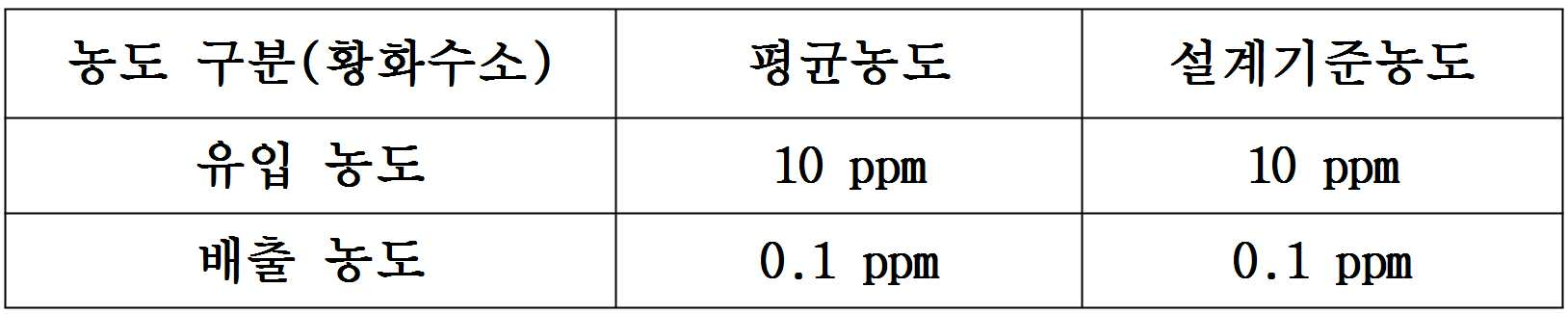
이에 본 발명자는 유기성 폐기물 처리장의 경우 악취발생원의 주 악취 원인이 음식물 폐기물, 가축분뇨의 전처리시설, 혐기성 소화시설에서 발생하는 점을 감안하여 주 악취원인 물질인 황화수소를 포함하는 총환원성 황 화합물(TRS(Total Reduced Sulfur))의 발생 농도를 10-20pp 예상하여 본 악취 처리시스템(A)의 처리 기준을 삼는 것이 적절함을 다음과 같은 일련의 다양한 현장 조사, 연구과정을 통하여 알게 되었다.
In view of the above, the present inventors consider that the main odor source of the odor generating source is generated from food waste, pretreatment of livestock manure, anaerobic digestion system, and total reducing sulfur compound (TRS) containing hydrogen sulfide as a main odor source. (Total Reduced Sulfur)) It was found through a series of various field surveys and studies that it was appropriate to set the treatment criteria for this odor treatment system (A) in anticipation of 10-20ppm concentrations.
각 발생원별 농도가 예측되므로, 합리적인 처리공법을 선정하기 위하여 농도조건을 다음 표와 같이 정리하였다. Since the concentration of each source is predicted, the concentration conditions are summarized in the following table to select a rational treatment method.
또 탈취처리의 가장기본적인 개념은 차단, 포집, 처리, 배출의 순서이므로 단순히 처리공법만 중점을 두어서는 부족한 점이 많으므로 종합적인 개념설정과 통합적 제어가 중요하데,In addition, since the most basic concept of deodorization treatment is the order of blocking, collecting, treating, and discharging, there are many shortcomings that focus only on the treatment method, so comprehensive concept setting and integrated control are important.
[차단]→[ 포집] →[처리]→[배출] 과정을 거치는 것이 악취처리의 기본 개념이다.
The basic concept of odor treatment is to go through [blocking] → [ collection] → [treatment] → [discharge] process.
차단block
악취발생원의 주변을 차단하여 불필요한 악취가 유입되지 않도록 함과 동시에 외부로 확산되는 것을 방지하는 기능을 갖도록 하여야 한다. 이로부터 악취발생량을 최소화하여 경제성도 함께 도모할 수 있도록 하여야 한다.
The surrounding area of odor generating source should be blocked to prevent unnecessary odor from entering and at the same time, it should have a function to prevent spreading to the outside. From this, the amount of odor generated should be minimized so that economic efficiency can be achieved.
포집Capture
악취를 정확히 포집하도록 적정한 후드구조와 설치위치, 에어 밸런스(Air Balance)를 감안하고 공기의 흐름을 유지하도록 하여야 한다. 처리장치까지의 효과적인 닥트의 배치와 포집경로도 함께 고려하여야 한다.The proper hood structure, installation location, and air balance should be taken to maintain the flow of air to accurately capture odors. Consideration should be given to the placement and collection of effective ducts to the treatment system.
처리process
악취의 특성, 성상, 농도 등을 고려하여 처리효율, 경제성, 부지면적 등을 감안하여 선정하도록 한다. The odor characteristics, characteristics, and concentrations should be considered in consideration of treatment efficiency, economic feasibility, and land area.
배출exhaust
최종 배출구는 주변에 미치는 영향을 고려하여 확산효과, 주변여건을 감안하여 적정한 높이를 계획하고, 배출농도의 측정이 가능하도록 측정구를 설치하도록 한다
The final outlet should be designed in consideration of the effect on the surroundings and the proper height in consideration of the diffusion effect and the surrounding conditions.
다음으로 처리대상 악취의 종류, 특히 유기성 폐기물 처리장의 처리공정에서 발생하는 주요 악취물질 종류 및 농도는 아래 표와 같이 암모니아가 높은 농도로 발생하고 있으며, 분뇨 처리장의 악취는 황화수소가 매우 높은 농도로 발생하고 있다. 유기성 폐기물의 병합 처리과정에 발생하는 악취물질이 약 20여 가지에 이르나, 그 중에서 발생량이 많고 제어가 용이한 황화수소(H2S)를 주요물질로 하여 설계제어 인자 기준으로 삼았다.Next, the types of odors to be treated, especially the main types and concentrations of odorous substances generated in the treatment process of organic waste treatment plants, are generated at high concentrations of ammonia, as shown in the table below. Doing. There are about 20 kinds of odorous substances generated in the combined treatment of organic wastes, but the major substance is hydrogen sulfide (H 2 S), which is large in quantity and easy to control, and was used as a design control factor.

또, 상기 발생 악취종류 중 분뇨처리 과정에서 많이 발생하고 검출 및 제어가 용이한 황화수소를 기준으로 하고, 암모니아, 아세트알데히드 와 혐기성처리과정에서 많이 발생하는 아민을 추가하여 4가지를 설계기준 인자로 선정하였다.In addition, four types of design odors were selected based on hydrogen sulfide, which is frequently generated in the manure treatment process and easy to detect and control, and added ammonia, acetaldehyde, and amines generated in the anaerobic treatment process. It was.

나아가 유기성 폐기물의 호기성퇴비화 또는 혐기성소화처리 과정에서 배출되는 발생악취의 농도 특성은 다음과 같다.Furthermore, the concentration characteristics of odor generated during aerobic composting or anaerobic digestion of organic waste are as follows.
[유기성 폐기물 혐기성 소화 처리시설에서 악취물질의 특성][Characteristics of Odor Substances in Anaerobic Digestion Treatment Plant]
(1) (One) 발생 악취의 농도가 높다.The concentration of odor generated is high.
유기성 폐기물의 반입, 처리과정에서 부패 또는 그 외의 여러 가지 반응이 이루어지면서 유기성 폐기물 내에 있는 채소 또는 고기류 및 가축 분뇨 등에서 심한 악취를 유발한다.Corruption or other reactions occur during the import and disposal of organic waste, causing severe odors in vegetables, meat and livestock manure within the organic waste.
(2)(2) 악취 발생의 Offensive odor 주 성분은The main ingredient is 황화수소 및 Hydrogen sulfide and 암모니아 이다Ammonia is ..
높은 유화 수소 및 암모니아 농도가 발생되는데 이는 분뇨 내에 있는 황(S) 계열의 유기 물질이 유화수소로 발생하고 음식물 내에 있는 질소계 성분이 혐기화 되면서 암모니아로 발생하는 것이다. 그러나 상대적으로 황화계 성분은 발생과정에서 질소계 성분과 반응하여 낮게 나타나는 경향이 있다.High emulsified hydrogen and ammonia concentrations are generated, which is generated by sulfur (S) -based organic matter in the manure as hydrogen emulsion and by the anaerobic nitrogen-based components in the food as ammonia. However, sulfide-based components tend to show low reaction with nitrogen-based components during development.
(3)(3) 수분이 많고, 먼지 발생량이 많다.There is much moisture, and there is much dust generation.
다량의 수분을 함유하고 있는 유기성 폐기물의 특성과 발효과정에서 발생하는 수분으로 인하여 높은 습도 조건을 조성하고 있으며, 유기성 폐기물의 혼합, 파쇄, 건조 등의 처리과정을 거치면서 많은 먼지가 악취유입과 더불어 상당량 유입되게 된다.Due to the characteristics of organic wastes containing a large amount of moisture and the moisture generated during fermentation, high humidity conditions are created.Many dusts are introduced along with the process of mixing, crushing and drying organic wastes. A significant amount will be introduced.
(4)(4) 고농도 악취로 인한 방지설비에서의 In facilities that are prevented by high odor 막힘방지Blockage 대책이 필요하다. Action is needed.
미생물의 과다 증식으로 인하여 담체의 과다한 코팅현상과 담체 공극의 막힘으로 미생물의 성장이 저해되고 처리효율도 낮아져 장기적이고 효율적인 운전유지가 어렵다. 따라서 상기의 특성을 파악하여 적정한 대비책을 마련하여 안정적인 처리와 경제성을 동시에 구비한 탈취방식의 선정이 중요한 문제로 대두되고 있는 것이다.Due to excessive growth of microorganisms, excessive coating of carriers and clogging of carrier pores inhibits the growth of microorganisms and lowers the treatment efficiency, making it difficult to maintain long-term and efficient operation. Therefore, selecting the deodorization method having both stable treatment and economical efficiency by preparing the appropriate countermeasures by grasping the above characteristics is an important problem.
(5)(5) 처리설비에서의 악취차단이 어렵다.It is difficult to block odor in processing equipment.
처리공정에서의 반입공정, 처리공정 및 발효공정 등을 거치면서 각각의 처리공정에서 발생하는 악취를 차단 밀폐하여 외부로 배출되는 것을 차단하기가 상당히 어렵다. 이를 위하여 충분한 밀폐장치와 차단구조 등으로 방지가 필요하다.
It is very difficult to block the odor generated in each treatment process through the import process, the treatment process and the fermentation process in the treatment process to prevent it from being discharged to the outside. To this end, it is necessary to prevent a sufficient sealing device and blocking structure.
<유기성 폐기물 병합처리(혐기성소화)과정에서 발생하는 악취물질의 특성><Characteristics of Odor Substances Generated from Combined Organic Waste Treatment (Aerobic Digestion)>

또, 총환원성 황화합물의 농도와 복합악취의 상관관계를 다음과 같이 방식으로 측정하였으며, 그 결과인 각 하수처리장별로 계산된 악취지수와 복합악취와의 관계를 나타낸 그래프를 도 9에 첨부하였다. '복합악취'란 두 가지 이상의 악취물질이 복합적으로 존재하면서 사람의 후각을 자극하여 불쾌감과 혐오감을 주는 냄새를 말한다.In addition, the correlation between the total reducing sulfur compound concentration and the compound odor was measured in the following manner, and a graph showing the relationship between the odor index calculated by each sewage treatment plant and the compound odor was attached to FIG. 9. 'Composite odor' refers to a smell that gives off a sense of displeasure and disgust by stimulating a human's sense of smell when two or more odorous substances are present in combination.
(1) 조사대상 지역인 6개의 하수처리장에서 각 화합물과 복합악취간 상관관계 분석을 통해서 본 하수처리장 악취 조사의 타당성을 평가하고자 함.(1) The purpose of this study was to evaluate the feasibility of this sewage treatment plant odor investigation through the correlation analysis between each compound and the mixed odor in six sewage treatment plants.
(2) 이를 위해서 각각의 하수처리장별로 검측된 화합물에 대한 개별 악취지수(아래 식 참조)를 계산한 이후에 이를 기하평균하여 각 지점의 통합 악취지수를 산정하였음. (2) For this purpose, the individual odor index for each compound detected by each sewage treatment plant (see below) was calculated and geometrically averaged to calculate the integrated odor index at each point.

(3) 각 하수처리장 지점별로 계산된 악취지수와 각 지점에 대한 복합악취 사이의 상관관계를 평가하였음. (3) The correlation between the malodor index calculated for each sewage treatment plant point and the complex malodor for each point was evaluated.
(4) 평가 결과, 악취지수가 커짐에 따라서 복합악취의 농도가 커짐을 확인함. 이를 통해서 본 조사 분석 방법이 적절히 이루어졌음을 확인함.(4) As a result of the evaluation, it was confirmed that as the malodor index increased, the concentration of the complex malodor increased. This confirms that the survey analysis method was properly performed.
(5) 또한 도 9에서, 이 분석 결과는 6개의 하수처리장 지점들에서 악취유발에 기여하고 있는 화합물들이 황화합물들임을 확인시키고 있음.(5) Also in FIG. 9, the analysis result confirmed that the compounds contributing to the malodor at six sewage treatment plant points were sulfur compounds.
(6) 다만, 도 9에서, 능내하수처리장과 난지하수처리장의 경우, 악취지수가 낮음에도 불구하고, 상대적으로 높은 복합악취가 검출되었는데, 이는 공정시험법에서 다루고 있는 화합물이 아닌 다른 화합물의 기여라고 판단됨. (6) However, in FIG. 9, in the NPC and NJI, despite the low odor index, a relatively high compound odor was detected, which is a contribution of a compound other than the compound covered by the process test method. Judged.
(7) 위의 odor index에 나타난 결과를 보면 도 9에서, 시흥시하수종말처리장과 서남하수처리장에서 odor index 및 복합악취가 낮게 검출됨.
(7) Looking at the results shown in the above odor index In Figure 9, the odor index and composite odor is detected low in the Siheung sewage treatment plant and Seonam sewage treatment plant.
다음으로 악취발생원으로부터 발생하는 악취를 효과적으로 포집하고, 배출경로를 설정하므로 포집 및 배출의 주안점은 다음과 같다.
Next, since the odor generated from the odor generating source is effectively collected and the discharge path is set, the main points of collection and discharge are as follows.
악취포집Odor Collection
배출설계의 주안점 Main points of emission design
(1) 악취발생원의 악취배출 특성에 맞도록 설계하여야 한다.(1) Designed to meet the odor emission characteristics of odor generating sources.
(2) 후드 및 직연결 시 단순 흡입이 아닌 악취배출공간에서의 공기흐름을 유도하도록 하여야 한다.(2) The hood and direct connection are to be intended to induce airflow in the odorous discharge space, not just suction.
(3) 포집되는 악취는 전체적인 균형을 맞춰 균일하게 포집하여 일부구간에서 적체되는 현상이 발생되지 않도록 하여야 한다.(3) Collected odors should be collected in a uniform manner in a balanced manner so that they do not accumulate in some sections.
(4) 포집닥트의 루트를 효율적으로 설정하여 흐름의 차단, 정지 및 주변장치와의 간섭 등을 고려하여야 한다.(4) The route of collecting duct is to be set efficiently to take into consideration the interruption of flow, stop and interference with peripheral devices.
(5) 각 후드 단말에는 Air Balance를 설정하기 위한 풍량조절담파와 측정구(Test Hole)을 설치하여야 한다.
(5) Each hood terminal is to be provided with air volume control sound wave and test hole for setting Air Balance.
한편, 악취를 적정처리한 후 외부로 배출하는 방법도 소홀히 할 수 없는 부분이다. 본 발명에서는 다음과 같이 설계하였다.On the other hand, the method of discharging the odor after the proper treatment is also a part that can not be neglected. In the present invention, it was designed as follows.
(1) 악취를 처리 후 배출은 완벽한 처리가 이루어진 경우 바이오 필터 후단에서 즉시 배출토록 하고, 바이오필터의 초기 미생물 증식 등으로 성능이 미달되는 경우 후단 활성탄 흡착 시설을 통하여 최종 배출토록 하였다.(1) After the treatment of odor, the discharge was immediately discharged from the rear stage of the biofilter. If the performance was insufficient due to the growth of the initial microorganisms of the biofilter, it was finally discharged through the activated carbon adsorption unit of the rear stage.
(2) 최종 배출구는 지상에서 최대한 높게 설계하면 좋으나, 주변 여건 등을 감안하여야 하므로 사람이 직접 접촉이 되지 않도록 하고, 주변 건물이나 구조물로 인한 와류현상 및 세류현상이 발생하지 않도록 높이를 유지하도록 하였다.(2) The final outlet should be designed to be as high as possible on the ground, but the surrounding conditions should be taken into consideration so that people do not come in direct contact with each other and maintain the height to prevent vortex and trickle phenomena caused by nearby buildings or structures. .
(3) 바이오 필타 후단 및 최종배출구에는 유화수소를 감지할 수 있는 센서를 부착하고, 악취를 분석하여 악취 저감에 만전을 기하도록 하였다.(3) At the rear end of the bio filter and the final discharge port, sensors for detecting hydrogen sulfide were attached and odor analysis was conducted to ensure odor reduction.
(4) 최종배출구 구조는 최종배출구 농도가 평균농도인 점을 감안하여 배출구내에서 원활이 혼합되도록 닥트와 편심접속처리 하였다.(4) The final outlet structure was eccentrically connected to the duct so that the final outlet concentration could be smoothly mixed in the outlet, taking into account the average concentration of the final outlet.
(5) 배출구 직경과 높이를 고려하여 바람과 자중을 견고히 지지하기 위하여 바닥 기초를 설치하여 고정시킨다.(5) In order to firmly support wind and self-weight in consideration of the diameter and height of the outlet, a floor foundation shall be installed and fixed.
(6) 배출구 몸체는 SS400 으로 제작하여 내부는 부식방지를 위하여 내식처리를 하고, 외부는 방식도장 마감토록 한다.
(6) The outlet body is made of SS400, so that the inside is corrosion-resistant to prevent corrosion, and the outside is finished with anticorrosive coating.
이와 같은 설계안에 기초하여 본격적인 악취의 처리를 진행하기 전에 유기성 폐기물 처리장이나 가축 분뇨 처리시설의 혐기성 소화 과정에서 발생하는 악취를 공정별로 포집하여 송풍기와 덕트 배관을 이용하여 이송하는 것이 필요하다. 유기성 폐기물 처리장이나 가축 분뇨 처리시설에서의 주요 악취 발생 공정은 (1) 전처리공정, (2) 탈수공정, (3) 혐기성소화 공정, (4) 폐수처리 공정이며, 이들 각 공정에 발생하는 풍량 설계는 혐기성 소화 시설과 폐수처리시설의 설계를 먼저 결정하고 난 후 결정하는 것이 바람직하다.
Before proceeding with the treatment of odor based on such a design, it is necessary to collect odor generated in the anaerobic digestion process of an organic waste treatment plant or a livestock manure treatment facility by process and transport it by using a blower and a duct pipe. The main odor generating processes in organic waste treatment plants or livestock manure treatment facilities are (1) pretreatment, (2) dehydration, (3) anaerobic digestion, and (4) wastewater treatment. It is advisable to determine the design of anaerobic digestion and wastewater treatment facilities first.
약액세정처리부(10), 특히 약액세정탑의 개략도인 도 4와 도 1 및 도 2에서, 약액 세정처리부(10)는 수용성 악취물질 처리에 적합하고 설치비가 저렴하며, 또한 분진처리가 가능하다는 장점을 갖는다. 또 약액 세정법은 순화수의 교체 주기에 따라 효율이 결정된다. 하지만 처리수 비용이 발생하고 비수용성 악취 처리가 어렵다는 단점이 있다. 4 and 1 and 2, which are schematic views of the chemical
알칼리성 및 산성 악취 제거를 위한 산성 세정탑 및 염기성 세정탑, 또는 단순 수(물) 세정탑, 또는 산성 및 염기성 세정 후의 중화처리 세정탑을 더 거칠 수 있는데,Acidic scrubber towers and basic scrubbers for alkaline and acidic odor removal, or simple water scrubbers, or neutralized scrubbers after acidic and basic scrubbers may be further roughened,
이들의 공통 구성을 도시한 도 4에서 확인할 수 있는 바와 같이, 하부의 세정수는 순환펌프(15p)에 의하여 펌핑되어 정량 제어를 위한 유량계(도 4에서 원형 'F' 표시, 이하 다른 도면에서도 동일함)와 압력계(도 4에서 원형 'P' 표시, 이하 다른 도면에서도 동일함)가 설치된 배관을 거쳐 분사노즐(13)을 통하여 충진체, 즉 메디아층(11) 상부로 투입(또는 분무 또는 살포)되고, 필요에 따라 약품탱크(15)에서 약액이 보충되고, 물공급부(17)에서 물이 공급되어 적정한 약액 농도 및 유량을 보장하게 된다. 악취를 포함한 공기는 흡기부(A1)를 통하여 흡입되어 메디아층(11)을 통과하며 최종적으로는 송풍기의 흡입력에 의하여 배출되어 다음 처리과정을 거치게 된다.As can be seen in Figure 4 showing their common configuration, the lower washing water is pumped by the
상기 메디아는 다양한 부재일 수 있으나 기본적으로 기액 접촉성을 높이기 위한 것이 바람직하다. 예를 들어 상기 메디아는 압출된 합성수지 튜브를 5~20mm 길이로 절단한 제품을 사용할 수 있고, 이러한 메디아는 메디아층 상하부에 메디아의 유실을 방지하며 약액이 통과될 수 있는 다수의 통공이 형성된 타공판을 도입한 상태에서, 약액(또는 세정수)를 살포(또는 분무)하는 경우 어느 정도 상하 타공판 사이에 약액이 채워지게 되고, 이때 메디아는 수류에 의하여 유동할 수 있도록 밀도가 약 0.92-0.96g/㎤이고 합성수지(예: 폴리에틸렌)의 재질로 이루어진 것이 바람직하다.The media may be a variety of members, but basically it is desirable to improve gas-liquid contact. For example, the media may be a product obtained by cutting an extruded synthetic resin tube into a length of 5 to 20 mm, and the media may include a perforated plate having a plurality of holes formed therein to prevent the loss of the media at the top and bottom of the media layer. In the introduced state, when spraying (or spraying) the chemical liquid (or washing water), the chemical liquid is filled to some extent between the upper and lower perforated plates, and the media has a density of about 0.92-0.96 g /
또 기액 접촉성을 높이도록 절단 튜브형 메디아는 충돌시 완충과 메디아 상호간 접촉 회전이 가능하도록 하는 외부 돌기들과 표면적을 크게하기 위한 내부 돌기들이 다수, 다양한 형태로 형성되어 있는 것이 바람직하다.In addition, it is preferable that the cutting tube-type media to enhance gas-liquid contact has a plurality of external protrusions for buffering and collision between media and the internal protrusions for increasing the surface area.
약액(또는 세정수)는 일정 주기 사용 후 후처리부(10p), 특히 폐수 처리 설비(WWTP, wastewater treatment plant)로 이송(또는 운송)되는 것이 바람직하다.The chemical liquid (or washing water) is preferably transported (or transported) to the
메디아층(11)과 분사노즐(13)들은 필요에 따라 도시된 1층 구조가 아닌 2층 이상 구성될 수 있다.The
한편, 메디아, 특히 절단 튜브형 메디아는 사용시간 경과에 따라 내외면에 이물질(스케일)이 끼게 되고, 이것이 2차 오염 또는 약액 사용 연한 감소의 원인이 될 수 있는 것으므로, 이 이물질(스케일)을 제거하여 약액 교체 주기를 늘려 운전비용을 줄임은 물론 세정처리효율 또한 일정 수준으로 유지할 수 있도록 하는 것이 바람직하다.On the other hand, media, especially cut-tube media, have foreign substances (scales) stuck on the inside and outside surfaces with time of use, and this may cause secondary contamination or a decrease in the age of chemical liquids. Therefore, it is desirable to reduce the operating cost by increasing the chemical replacement cycle and to maintain the cleaning treatment efficiency at a constant level.
이에 본 발명에서는 도 8에 도시된 바와 같이, 재생교반수단(19)을 도입할 것을 고려하였다. 이 재생교반수단(19)은 메디아층 상하부의 타공판 사이에 설치되어 메디아를 휘젓는 것으로, 모터(19C)와 직결 또는 감속기를 개재한 상태로 연결되는 회전축(19A)과, 이 회전축 외주면에 다수 돌출 결합된 교반날개(19B)로 이루어진다.Thus, in the present invention, as shown in Figure 8, it was considered to introduce a regeneration stirring means (19). The regenerative stirring means 19 is installed between the upper and lower perforated plates of the media layer to stir the media. The
또 교반날개(19B)와 회전축(19A)은 파이프 형태로 약액(또는 세정수)의 투입, 배출이 가능하며, 세정수는 교반날개(19B)의 분사공(H)으로 배출되어 보다 원활한 메디아의 세척 재생은 물론 악취 처리를 위한 기액 접촉 효율을 더 높이는 기능을 한다. 필요에 따라 약액 분사공은 중앙 회전축에도 도입될 수있다.In addition, the stirring blade (19B) and the rotating shaft (19A) can be added and discharged the chemical liquid (or washing water) in the form of a pipe, the washing water is discharged to the injection hole (H) of the stirring blade (19B) to smooth the media It also functions to increase the efficiency of gas-liquid contact for odor treatment as well as washing regeneration. If necessary, the chemical liquid injection hole can also be introduced into the central rotating shaft.
나아가 이물질 유입에 의한 펌프 손상과 노즐 구멍 막힘 현상을 방지하기 위하여 필터가 펌프(15p) 전단에 설치되는 것이 바람직하며, Furthermore, in order to prevent the pump damage and the nozzle hole clogging due to the inflow of foreign substances, it is preferable that the filter is installed in front of the
도 8의 일점쇄선 원 내에서 확인할 수 있는 바와 같이, 교반날개(19B)의 분사공(H) 막힘 현상을 해결하기 위하여 별도로 교반날개를 내부관(19a)과 외부관(19b)으로 구성하고, 외부관의 배수공(h1)은 상대적으로 크게(예: 단면적이 1~4㎠ 정도) 형성하고, 내부관의 배수공(h2)은 상대적으로 작게(예: 단면적이 0.1~0.8㎠ 정도)로 하며, 내부관(19b)은 염가의 합성수지 호스를 사용하여 배수공(h2)이 막힌 경우 내부관을 분리하여 폐기하고 새로운 내부관을 삽입 장착하는 방식을 취할 수 있다. 필요에 따라 교체시 내외부관(19b)(19a)의 배수공(h2)(h1)의 상호 일치 용이성을 확보하기 위하여 내부관은 단면이 원형이 아닌 비원형(다각형, 타원형 등)으로 하거나 적어도 내부관 외면에 길이 방향 요철을 갖는 형태로 하고, 적어도 외부관의 내면은 내부관의 외주면 형상에 상응하는 형태로 하여 배수공(h2)(h1)간 정위치 결합이 쉽게 이루어지도록 할 수 있다.
As can be seen in the dashed-dotted circle of Figure 8, in order to solve the clogging of the injection hole (H) of the stirring blade (19B), the stirring blade is composed of the inner tube (19a) and the outer tube (19b), The drainage hole h1 of the outer tube is relatively large (for example, about 1 to 4 cm 2), and the drainage hole h2 of the inner tube is relatively small (for example, about 0.1 to 0.8 cm 2). The
다음 표에 약액세정법의 원리 및 대상 가스를 정리하였다.The following table summarizes the principle of chemical cleaning and the target gases.

다음으로 개략도인 도 5와 도 1 및 도 2를 참조하여 바이오필터부(20)를 살펴본다.Next, the
바이오필터부(20)는 유지비용이 저렴하고 일부 물질에 대해 아주 높은 처리효율을 보인다. 하지만 상대적으로 설치면적이 크고 물질의 생물학적 처리가 어렵다는 단점이 있다. The
바이오필터의 핵심 기술은 악취를 분해할 수 있는 미생물과 악취 물질을 흡수하고 미생물들의 서식 공간을 제공하여 미생물의 기능을 유지시킬 수 있는 메디아 충진부(23)로 구성되며, 바이오필터의 미생물에 의한 악취물질의 분해는 다음 일련의 공정에 의해서 제거된다. The core technology of the biofilter consists of a
(1) 악취물질과 유기화합물을 함유한 오염가스가 물공급부(25B)에서 보충된 하우징 하부의 물이 순환펌프(21p)에 의하여 펌핑되어 상부 노즐에서 살포되는 습도조절기(21)를 거친다. 이후 역시 물공급부(25A)에서 공급된어 노즐에서 물이 살포되고 있는, 바이오 필터의 핵심인 메디아 충진부(23)를 통과하게 된다.(1) Water in the lower part of the housing supplemented by the
(2) 메디아 충진부(23)에 유입된 물질들이 다공성 메디아(담체)의 표면에 부착되어 생물막을 형성하고 있는 미생물 층에 흡착되고,(2) the substances introduced into the
(3) 흡착된 물질들은 미생물의 생장에 필요로 하는 탄소원이나 기타 영양분으로 이용되어 무취/무해한 CO2, 물, 미생물, 및 무기물(황산이나 질산)로 분해되거나 미생물의 증식과 활동에 필요로 하는 에너지원으로 이용된다.(3) Adsorbed materials are used as carbon sources or other nutrients required for the growth of microorganisms and are decomposed into odorless / harmless CO2, water, microorganisms, and minerals (sulfuric acid or nitric acid) or energy required for the growth and activity of microorganisms. Used as a circle.
(4) 오염공기에 함유되어 있던 오염물질은 메디아 충진부(23) 층을 통과하면서 미생물의 분해작용에 의해 제거된 후 (4) After the contaminants contained in the contaminated air are removed by the decomposition of the microorganisms while passing through the
바이오필터부(20)에서 처리된 공기의 오염 정도에 따라 송풍기에 의하여 토출되어 배기부(A2a)로 이송되거나, 바이오필터부(20)에서 처리된 공기의 오염 정도에 따라 이후의 흡착처리부(30)로 이송된다.It is discharged by the blower according to the degree of contamination of the air processed by the
역시 사용주기가 지나 교체가 필요한 경우 사용된 세정수는 후처리부(20p), 특히 폐수 처리 설비(WWTP, wastewater treatment plant)로 이송(또는 운송)되는 것이 바람직하다.
In addition, when the replacement cycle is necessary after the use cycle, the used washing water is preferably transferred (or transported) to the after-
이어 개략도인 도 6과 도 1 및 도 2를 참조하여 흡착처리부(30)를 살펴본다.Next, the
흡착처리부(30)는 대부분의 악취 물질 처리가 가능하고 흡착제의 교체 주기에 따라 효율이 결정된다. 하지만 활성탄 교체 비용이 발생하고 고농도 악취 처리시 비용이 과다한 문제점이 있다. 따라서 도 1 및 도 2와 같이 가능한 후단에 설치하여 전단에서의 처리에도 악취물질이 기준을 충족할 정도로 제거되지 않은 것으로 센싱, 판정된 경우 거치는 것이 바람직하다.The
다양한 다공성 알갱이, 특히 활성탄이 충진된 흡착처리부(30)는 악취의 주물질인 암모니아 및 아민을 효과적으로 흡착처리하기 위하여 염기성 가스와 반응할 수 있는 흡착제를 충진하여 처리하며, 최종적으로 처리 가스는 배기부(A2b)를 통하여 방출된다. 흡착제는 기본적으로 내부에 미세한 세공이 형성되어 비표면적이 넓고 흡착성이 강한 특성을 지니고 있다.
The
한편, 도 7에 도시된 악취 농도 및 처리유량별로 적절한 적용 처리 기술을 보인 그래프에 기초하여 다른 악취 처리수단을 적절한 위치에 추가 배열할 수 있다.
On the other hand, other odor treatment means may be additionally arranged at an appropriate position based on a graph showing an appropriate application treatment technique for each odor concentration and treatment flow rate shown in FIG. 7.
다음으로 다시 도 1 내지 도 3을 참조하여 본 발명에 따른 악취 처리시스템의 악취 능동감시 기능 및 처리공정을 보다 구체적으로 살펴본다.Next, the odor active monitoring function and the processing process of the odor treatment system according to the present invention will be described in more detail with reference to FIGS. 1 to 3.
보다 완벽하게 악취방지시설의 처리효율을 감시하고 악취방지시설의 경제적인 유지관리를 위하여 통신망, 특히 CDMA 네트워크(40W)를 이용한 악취 관제 시스템(40S)을 구축하는 것이 바람직하며, 이 때 수분, 약품 및 영양분 공급 공정인자들을 자동화하고 미생물의 성장을 제어할 수 있어야 한다. 또 악취처리 공정의 온라인 감시를 통하여 악취 방지시설 운영의 신뢰성을 제공한다.In order to more fully monitor the treatment efficiency of the malodor prevention facility and to economically maintain the malodor prevention facility, it is desirable to establish a
이를 위하여 악취발생원(P), 특히 유기성 폐기물 처리장에서 주로 발생하여 악취강도 및 악취 기여도가 높은 황화수소, 메틸메르캅탄, 황화메틸, 이황화메틸 등 총환원성황화합물 센서, 즉 TRS(Total Reduced Sulfur) 센서를 이용하여 연속 자동 측정함으로써,To this end, total reducing sulfur compounds such as hydrogen sulfide, methyl mercaptan, methyl sulfide, and methyl disulfide, such as hydrogen sulfide (P), which occur mainly in organic waste treatment plants and have high odor intensity and odor contribution, are used. By continuous automatic measurement
(1)약액세정처리부(10), 특히 세정탑의 경제적인 악취처리 유지관리,(1) chemical liquid cleaning processing unit (10), in particular, the maintenance and management of economic odor treatment,
(2)바이오필터부(20)의 정상 가동 감시 및 악취처리 효율 감시,(2) the normal operation monitoring and odor treatment efficiency monitoring of the
(3)바이오필터부(20)의 오동작 또는 악취처리효율 저하시 배기밸브를 차단하고 흡착처리부(30), 즉 활성탄 흡착탑에 의한 배출 가스 3차 처리 결정, (3) When the
(4)본 악취 처리시스템(A)에 사용되는 약액세정처리부(10) 및 기타 처리공정에서의 약품 투입량, 바이오필터 여재 교체 주기, 활성탄(흡착제) 교체 주기를 결정 자료 제공,(4) Providing the data for determining the chemical input amount, chemical filter replacement cycle, and activated carbon (adsorbent) replacement cycle in the
(5)악취 관제 프로그램을 이용하여 악취발생원(P), 특히 유기성 폐기물 처리장에서의 악취 발생원을 최소화한다(5) Minimize odor sources (P), especially odor sources in organic waste treatment plants, using odor control programs.
는 목적들을 구현한다.
Implements the objectives.
본 발명에 따른 악취 처리시스템(A)에서는 약액세정처리부(10), 바이오필터부(20), 흡착처리부(30)의 유입구 또는 배출구, 또는 이들 모두에 악취감지센서가 구비되는 것이 바람직하다. In the odor treatment system A according to the present invention, it is preferable that an odor detection sensor is provided at the inlet or outlet of the chemical liquid
본 명세서에서 '유입구' 및 '배출구'는 동일하게 지칭하고 있으나 약액세정처리부(10), 바이오필터부(20), 흡착처리부(30) 각각의 것을 나타내며 서로 혼동을 일으키지 않는다.In the present specification, 'inlet' and 'outlet' refer to the same, but represent the chemical
도 1 및 도 2에서는 약액세정처리부(10), 바이오필터부(20), 흡착처리부(30)가 연속 배치된 상황을 고려하여 약액세정처리부(10) 및 흡착처리부(30)의 유입구 및 배출구에 각각 센서(S1a,S1b,S2a,S2b)가 도입되어 있고, 약액세정처리부(10)를 알칼리성 및 산성 악취 제거를 위한 산성 세정탑(10A) 및 염기성(10B) 세정탑으로 구성할 경우 이들 사이에 별도의 센서(S1c)를 더 도입하였다. 1 and 2, in consideration of the situation in which the chemical liquid
즉, 악취 측정 지점은That is, the odor measuring point
(1) 센서 S1a - 약액세정처리부(10) 유입 부분(즉, 흡기부(A1)): 유기성 폐기물에서 발생하는 악취를 송풍기와 덕트 시설을 통해 1차 악취 방지시설인 2단 세정탑(산성 및 염기성)(10A)(10B) 유입 부분에서 측정(1) Sensor S1a-chemical liquid
(2) 센서 S1b - 약액세정처리부(10) 배출 부분(바이오필터부(20) 유입 부분(예:TRS센서)): 2단 세정탑에 의해 처리된 악취를 측정 (2) Sensor S1b-chemical
(3) 센서 S2a - 바이오필터부(20) 배출 부분(예:TRS센서): 바이오필터에 의해 처리된 악취를 측정(배기부(A2a) 또는 후속 흡착처리부(30) 이송 여부 결정)(3) Sensor S2a-
(4) 센서 S2b - 흡착처리부(30) 배출 부분(필요시): 바이오필터부(20)에서 유출 되는 악취가 기준치를 초과하여 흡착처리부(흡착탑)에 의해 처리할 경우 그 배출 농도 측정(4) Sensor S2b-
(5) 센서 S1c - 약액 세정탑에서 산세정과 알칼리세정 공정 사이에 pH 측정
(5) Sensor S1c-pH measurement between pickling and alkali washing in chemical cleaning tower
먼저, 약액세정처리부(10), 특히 처리탑의 특징은First, the characteristics of the
(1) 복합악취 처리능력이 탁월하다 : 음식물처리에서 배출하는 20여종의 물질과 다양한 성상 등으로 구성된 복합악취를 제거하는데 적합하다,(1) Excellent ability to handle complex odors: It is suitable for removing complex odors composed of 20 kinds of substances discharged from food processing and various characteristics.
(2) 비수용성의 악취물질 처리에도 우수하다 : 1차 전기분해수를 이용한 유기물질의 산화분해로 비수용성 물질의 분해에도 우수한 성능을 제거효율을 갖는다,(2) Excellent for the treatment of non-aqueous malodorous substances: It has excellent removal efficiency even in the decomposition of non-aqueous substances by oxidative decomposition of organic substances using primary electrolytic water.
(3) 폐수발생량을 대폭 줄여 준다 : 세정탑 수조 내에서 유기물 및 용해된 악취물질을 분해시킴으로 내부 염농도를 낮게 유지할 수 있어 수조 내 교환횟수를 줄여준다. 또한 배출시 농도도 낮게 배출시킬 수 있다 ⇒ 70 % 이상 폐수 발생량을 저감시킨다(3) Significantly reduce the amount of wastewater generated: The internal salt concentration can be kept low by decomposing organic substances and dissolved odorous substances in the washing tower tank, thus reducing the number of exchanges in the tank. In addition, the concentration can be lowered when discharged ⇒ 70% or more reduced wastewater generation
라는 것이다.It is called.
구체 설계시에는 처리대상의 용량에 따라 악취 발생이 변화되므로 유기성 폐기물 처리용량 결정에 따라 2단 세정탑의 부피 및 표면적이 결정된다.In the concrete design, the odor generation is changed according to the capacity of the object to be treated. Therefore, the volume and surface area of the two-stage scrubber are determined by the determination of the amount of organic waste treatment.
한편, 약액세정처리부(10)의 처리 원리를 다음의 표로 정리하였다.On the other hand, the treatment principle of the chemical liquid

다음으로 바이오필터부(20)는 악취를 분해할 수 있는 미생물과 악취 물질을 흡수하고 미생물들의 서식 공간을 제공하여 미생물의 기능을 유지시킬 수 있는 메지아, 즉 담체로 구성되며, 구체 메커니즘은 앞서 기술하였다. 유기성 폐기물 처리 공정에서 발생하는 악취 처리용량에 따라 바이오필터부의 단위별 압력 강화와 총 압력 강화가 결정되므로, 이를 계산하여 설계한다.
Next, the
이어서 흡착처리부(30)를 구성하는 흡착제는 활성탄의 경우 그 특성이Subsequently, the adsorbents constituting the
(1)흡착제는 염기성가스를 흡착할 수 있는 종류를 채택하여 미처리된 암모니아, 아민류 및 중성 악취가스를 흡착처리토록 한다.(1) Adsorbents are used to adsorb basic gases to adsorb untreated ammonia, amines and neutral odor gases.
(2)흡착제의 형태는 성형에 의한 원통형으로 10~13mmD x 10~30mmL 크기를 지닌다. 그러므로 성형 형태를 잘 유지하여 부서지는 여과성능이 높으며, 부서지는 현상이 적고 압력손실이 비교적 적다.(2) The type of adsorbent is cylindrical by molding and has a size of 10 ~ 13mmD x 10 ~ 30mmL. Therefore, it maintains the molding form well, so that the filtration performance is high, there is little breakage phenomenon and relatively low pressure loss.
(3)색상은 적, 흑갈색 또는 회갈색을 지닌다.(3) The color is red, dark brown or gray brown.
(4)겉보기 비중은 0.7kg ± 0.1kg / L(4) The apparent specific gravity is 0.7kg ± 0.1kg / L
(5)암모니아 및 아민 흡착능력 : 70 ~ 100 g/kg(5) Ammonia and amine adsorption capacity: 70 ~ 100 g / kg
이다.
to be.
흡착처리부(30)를 구현한 흡착탑은Adsorption tower implementing the
(1)체류시간 : 1초 이상(1) Duration of stay: 1 second or more
(2)흡착제 종류 : 염기성가스 흡착제(2) Type of adsorbent: basic gas adsorbent
(3)흡착제 교체주기 : 4년(3) Adsorbent replacement cycle: 4 years
을 설계기준으로 한다.
Is the design criterion.
또 가스 흡착탑의 경우In the case of gas adsorption tower
(1)내부 흡착제의 중량을 지지할 수 있는 튼튼한 구조로 한다.(1) It is to be durable structure that can support the weight of internal adsorbent.
(2)내부의 가스흐름 및 압력에 효과적 대응이 가능한 형태를 가져야 한다.(2) It should have a form that can effectively cope with internal gas flow and pressure.
(3)충진된 흡착제가 외부로 새어나오지 않도록 적절한 구조여야 한다.(3) The structure of the adsorbent is to be suitable so that it does not leak out.
(4)흡착제 교체 시 주변 공간이 충분하여 원활한 작업이 되도록 하여야 한다.(4) When adsorbent is replaced, sufficient space is to be provided for smooth operation.
(5)본체는 일반탄소강판을 사용하고 부식방지를 위해 표면에 에폭시 도장을 한다.(5) The body is made of ordinary carbon steel and epoxy is coated on the surface to prevent corrosion.
는 사항들을 제작 특기사항으로 하는 것이 바람직하다.
It is desirable to make the matters the production specialty.
나아가 가스흡착탑은 Furthermore, the gas adsorption tower
(1)전단 세정탑 및 바이오필터에서 충분히 처리된 악취물질을 정상적으로 제거하여 성능보증 기준을 준수할 경우에는 흡착탑 바이패스를 통하여 외기로 배출토록 한다.(1) If odorous substances sufficiently treated in the shear scrubber and biofilter are normally removed and comply with the performance assurance standards, they should be discharged to outside air through the adsorption tower bypass.
(2)전단에서 충분히 처리되지 않거나, 갑작스런 농도증가로 추가 처리가 필요할 경우에는 바이패스라인을 닫고 흡착탑을 경유하여 정상처리토록 한다.(2) If the shear is not sufficiently treated or if additional treatment is needed due to sudden concentration increase, close the bypass line and allow normal treatment via the adsorption tower.
(3)흡착탑 특성상 흡착제가 포화될 경우 교체가 필요하므로 운전유지비를 감안하여 효과적인 운영이 필요하다.(3) Due to the characteristics of the adsorption tower, if the adsorbent is saturated, it needs to be replaced.
는 사항들을 운영방법으로 하는 것이 바람직하다.It is advisable to make the matters the operating method.
또 흡착탑은 유기성 폐기물 처리 공정에서 발생하는 악취 처리용량에 따라 흡착탑의 부피와 표면적이 결정된다.
In addition, the volume and surface area of the adsorption tower are determined by the odor treatment capacity generated in the organic waste treatment process.
이상과 같은 본 발명의 악취 처리시스템(A)에 적용된 각 공정(10)(20)(30)과 다른 악취 가스 처리공법 비교사항을 다음 표로 정리하였다.Each step (10) (20) (30) and other odor gas treatment method applied to the odor treatment system (A) of the present invention as described above are summarized in the following table.

따라서, 상기 표의 비교결과를 토대로 특히 유기성 폐기물 처리장의 각 공정에서 발생되는 악취는 일반 악취와 공정 악취로 구분하여 처리방법 및 처리 단계별로 처리하는 것이 바람직한데, 통상 1단 약액세정과 2단 바이오필터로 처리한다. 그러나, 이런 기본 공정에서 악취제거효율이 낮을 경우나 점검 및 수리할 경우에는 활성탄흡착탑을 이용하여 악취를 처리한 후 최종 배출하는 것이 바람직하다.Therefore, on the basis of the comparison results in the above table, in particular, the odors generated in each process of the organic waste treatment plant are preferably divided into general odors and process odors and are treated according to treatment methods and treatment stages. To be processed. However, when the odor removal efficiency is low in the basic process or when checking and repairing, it is preferable to discharge the odor after treating the odor using an activated carbon adsorption tower.
따라서 [약액세정처리부(10)] → [바이오필터부(20)] → [흡착처리부(30)( 비상시 )]를 거쳐 처리하는 것을 기본으로 하며, Therefore, the chemical liquid
이 때 본 악취 처리시스템(A)의 구성 및 설계 유입 및 최종 배출 농도는 다음 표와 같다.At this time, the composition, design inflow and final discharge concentration of the odor treatment system (A) is shown in the following table.

본 발명에 따른 악취 처리시스템(A)에서 [약액세정처리부(10)] → [바이오필터부(20)] → [흡착처리부(30)( 비상시 )]으로 이루어진 다단 혼성 처리 공법은In the odor treatment system (A) according to the present invention is a multi-stage hybrid treatment method consisting of [ chemical cleaning unit 10] → [biofilter unit 20] → [adsorption unit 30 ( emergency )]
① 약액세정탑에서 산성가스 및 알칼리성 가스를 안정적으로 제거한다.① Stable removal of acid gas and alkaline gas from chemical liquid washing tower.
② 필요시 플라즈마장치 또는 전기분해장치를 도입하여 악취분해에 소요되는 약품비를 대폭적으로 절감시켜 준다.② If necessary, plasma equipment or electrolysis equipment is introduced to drastically reduce the chemical cost required for odor decomposition.
③ 바이오필터에서 중성가스 및 다양한 악취물질을 미생물을 이용하여 제거한다.③ Neutral gas and various odorous substances are removed by using microorganism.
④ 바이오필터의 배출 가스 농고 기준치를 초과하거나 바이오필터의 처리효율이 떨어질 경우 흡착탑 3차리를 하여 최종 배출한다.④ If the exhaust filter of biofilter exceeds the standard value or the treatment efficiency of the biofilter is low, the third stage of the adsorption tower is discharged.
⑤ 여러 가지 공법이 상호 보완하여 고농도 악취는 물론 다양한 악취 종류에 대응 가능하다.⑤ It is possible to cope with various kinds of odors as well as high concentration odors by complementing various methods.
⑥ 운전의 유연성을 주어 농도의 변화에 용이하게 대응할 수 있다.⑥ It can easily cope with the change of concentration by giving flexibility of operation.
⑦ 유지관리가 용이하고 취급운영이 편리하다.⑦ Easy maintenance and convenient handling and operation.
라는 특징을 갖는다.
It has a characteristic.
또 도 3 및도 2과 같은 악취 관제 시스템(40S)은 악취방지시설의 처리효율을 감시하고 악취방지시설의 경제적인 유지관리를 위하여 통신망, 특히 CDMA 네트워크(40W)를 이용하여 구축된다.In addition, the
산성 세정탑(10A) 및 염기성 세정탑(10B)에서 산세정과 알칼리세정 공정 사이에 pH 측정을 위한 센서(S1c) 외에는, 약액세정처리부(10) 및 흡착처리부(30)의 유입구 및 배출구에 각각 배치된 센서(S1a,S1b,S2a,S2b)는 기본적으로 TRS(Total Reduced Sulfur) 센서를 포함한다. In addition to the sensor S1c for pH measurement between the acid washing and alkaline washing processes in the
본 명세서에서 '약액세정처리부의 유입구 또는 배출구'는 산성 세정탑(10A) 및 염기성 세정탑(10B) 각각의 유입구 또는 배출구를 포함하는 개념이다.In the present specification, the inlet or outlet of the chemical cleaning unit is a concept including an inlet or outlet of each of the
이러한 총환원성 황화합물 센서는 유입되는 시료가스 중에 포함된 환원성 황화합물질을 열산화시켜, 아황산가스로 변환시키고 이를 측정하는 기기이다. 아황산가스는 자외선(UV)를 만나면 여기되는데, 여기서 발생하는 빛의 강도로 샘플가스 중의 아황산가스의 농도를 측정한다. 측정기의 교정은 H2S 표준가스를 이용한다. 측정은 PMT, dark offset, UV lamp ratio, 잔류 빛, 샘플가스의 온도와 압력과 함께 사용하여 최종 농도를 계산한다. 계산된 농도 값은 측정기의 내부 데이터 저장 시스템(iDAS Section)에 저장 되어, 사용자에게 아날로그 신호 출력 및 다양한 디지털 신호, 측정기 화면으로 표시된다.
The total reducing sulfur compound sensor is a device for thermally oxidizing the reducing sulfur compound contained in the incoming sample gas, converting it into sulfur dioxide, and measuring the same. Sulfur dioxide is excited when it encounters ultraviolet (UV) light, and the concentration of sulfur dioxide in the sample gas is measured by the intensity of light generated. Calibrate the meter using H 2 S standard gas. The measurement is used with PMT, dark offset, UV lamp ratio, residual light, and sample gas temperature and pressure to calculate final concentration. The calculated concentration values are stored in the instrument's internal data storage system (iDAS Section) and displayed to the user as analog signal outputs and various digital signals and meter screens.
도 3에서, 본 악취 관제 시스템(40S) 구축에는 In FIG. 3, the present
① 자료 관리 프로그램① Data Management Program
- 총환원성황화합물센서에서 측정된 데이터 디지털 표시-Digital display of data measured by total reducing sulfur compound sensor
- pH센서에서 측정된 데이터 표시-Display measured data from pH sensor
- 악취방지시설 효율 그래프 표시 -Display odor efficiency graph
② 기상 자료 프로그램 ② Weather data program
- 기상 센서에 측정된 데이터 디지털 표시-Digital display of measured data on weather sensor
③ 운영 제어 프로그램③ Operation control program
- 악취 방지 시설의 약품 투입 제어-Chemical input control of odor prevention facilities
- 악취 방지 시설의 유지관리-Maintenance of odor prevention facilities
과 같은 관제프로그램들이 사용된다.
Control programs such as
또 서버(41)에는 측정된 자료의 데이터 베이스가 구축되고, 관리자는 관제PC(43)의 모니터를 통하여 운영자 데이터 감시 화면을 확인하면서 실시간으로 악취방지시설 이상 유무를 확인하고 적절한 조치를 취할 수 있다.
In addition, the database of the measured data is built in the
나아가 각 센서(S1a,S1b,S1c,S2a,S2b)를 위한 중계부, Furthermore, the relay unit for each sensor (S1a, S1b, S1c, S2a, S2b),
특히 약액세정처리부(10) 유입구 및 배출구에 구비된 센서(S1a,S1b,S1c)가 TRS센서와 pH센서인 비해, 흡착처리부(30) 유입구 및 배출구에 구비된 센서(S2a,S2b)가 TRS센서와 기상센서In particular, the sensors (S1a, S1b, S1c) provided at the inlet and outlet of the chemical
(기상센서는 대기 중의 미세먼지, 자외선, 풍향, 풍속, 온도, 습도 등을 측정하여 자료를 수집하고 중앙제어센터, 즉 제어부(40)로 송신하여 처리가스 배출기준 충족 여부 판정에 오류가 발생하지 않도록 한다)이므로(The weather sensor collects data by measuring fine dust, ultraviolet ray, wind direction, wind speed, temperature, humidity, etc. in the air and transmits the data to the central control center, that is, the
이에 알맞게 중계부를 이원화(S1)(S2)(도 1에서는 구분 없이 센싱신호 중계부를 편의상 'S'로 지시함)하며, 이에 맞게 데이터 로거(Data Logger)(D/L)를 2세트 도입하였다.Accordingly, the relay unit is dualized (S1) and S2 (in FIG. 1, the sensing signal relay unit is designated as 'S' for convenience), and two sets of data loggers (D / L) are introduced accordingly.
각 데이터 로거(Data Logger)(D/L)의 하드웨어 사양은 The hardware specifications of each Data Logger (D / L)
i) CPU : Intel Pentium Dual Core 이상, ii) Main Memory : 500MB 이상, iii) ODD : DVD COMBO 20x 이상, iv) HDD : 80G 이상 (HDD 하드랙 장착), v) I/O : PS2 Keyboard, mouse, USB 4port, vi) 10/100MBps Ethernet Card 또는 상위 사양, vii) GrapHic : 32MB SDRAM 이상, viii) Power : 300W 이상, ix) Monitor :6.5" TFT LCD 이상, x) 전원이 단절된 후 복구되었을 때 자동 부팅되어야 함, xi) Ethernet RJ 45 연결, xii) RS232C Serial 2 Port 이상i) CPU: Intel Pentium Dual Core or above, ii) Main Memory: 500MB or above, iii) ODD: DVD COMBO 20x or above, iv) HDD: 80G or above (HDD hard rack installed), v) I / O: PS2 Keyboard, mouse, USB 4port, vi) 10 / 100MBps Ethernet Card or higher specification, vii) GrapHic: 32MB SDRAM or above, viii) Power: 300W or above, ix) Monitor: 6.5 "TFT LCD or above, x) Auto boot when power is restored after disconnection Xi)
과 같은 조건을 을 충족하는 것이 바람직하다.It is desirable to meet the following conditions.
또 각 데이터 로거(Data Logger)(D/L)의 소프트웨어 사양은 In addition, the software specifications of each Data Logger (D / L)
i) 악취측정기의 실시간 측정값 및 진단정보 수집, ii) 접속사양 : RS232C, iii) 통신방식 : D/L 폴링, iv) 산/염기 투입모듈 제어, v) 접속사양 : Digital In, Digital Out, vi) 통신방식 : 로컬 또는 원격명령에 의한 접점제어, vii) 수동, 자동 모두 가능, viii) 자료 조회 (테이블 형식, 그래프 형식), ix) 실시간 : 최소 30초 마다 자료 갱신, x) 5분자료 : 실시간 자료 기반으로 5분자료 생성 및 조회, xi) 시간자료 : 5분자료 기반으로 시간 자료 생성 및 조회, xii) 상료 : 측정기 상태자료 수집 및 조회 (실시간), xiii) 상태 설정, xiv) 보수중 등 수동으로 상태 설정, xv) 원격 제어 처리 기능, xvi) 시간 변경 (Time-set)에 따라 현재 시간 변경, xvii) 자료 재전송 요구 (Dump)에 따라 요청 범위의 자료 전송, xviii) 자료 보관, xix) 5분 자료 5개월 이상 보관 가능, xx) 로그 기능, xxi) 관제시스템과의 통신 전문을 파일 형태로 기록, xxii) 프로그램 실행시 발생될 수 있는 각종 에러 및 경고 사항 기록i) Collection of real-time measurement values and diagnostic information of odor measuring instruments, ii) Connection specifications: RS232C, iii) Communication method: D / L polling, iv) Acid / base input module control, v) Connection specifications: Digital In, Digital Out, vi) Communication method: contact control by local or remote command, vii) Manual or automatic, viii) Data inquiry (table format, graph format), ix) Real time: Data update every 30 seconds, x) 5 minutes data : 5 minutes data generation and inquiry based on real time data, xi) Time data: 5 hours data generation and inquiry based, xii) Completion: Collecting and querying instrument status data (real time), xiii) Status setting, xiv) Repair Manual setting of state, xv) remote control processing function, xvi) current time change according to time-set, xvii) data transfer in request range according to data retransmission request, xviii) data storage, xix) Keep 5 minutes data for more than 5 months , Xx) log function, xxi) written communications professional with a control system as a file, xxii) the program can be generated in various errors and warnings logged during run
과 같은 조건을 을 충족하는 것이 바람직하다.
It is desirable to meet the following conditions.
나아가 악취처리 공정의 온라인 감시를 위한 통신망, 특히 CDMA 네트워크(40W)는 3세트 이상 구비되며, 하드웨어 사양은 i) CDMA 무선 모듈, ii) 속도 115200 BPS 과 같은 조건을 을 충족하는 것이 바람직하다.Furthermore, more than three sets of communication networks, especially
다음으로 약액세정처리부(10), 즉 알칼리성 및 산성 악취 제거를 위한 산성 세정탑(10A) 및 염기성 세정탑(10B)에서 유입 악취가스의 오염상태에 맞게 분무 약액 종류, 유량, 시간을 제어부(40)가 제어하도록 하는 산염기 투입모듈(45)(펌프, 유량계, 압력계 등으로 구성됨)의 제어를 위한 Digital In/Out 제어 모듈(DI/DO 제어모듈)은 1세트(중계부(S1)측) 구비된다. Next, in the
그 하드웨어 사양은 i) Digital In, ii) Port : 4 Port 이상, iii) Interface : 광커플러를 사용한 분리방식, iv) 최대 입력 전압 : 24 V, v) Digital Out, vi) Port : 4 Port 이상, vii) Interface : 릴레이를 사용한 분리방식, viii) 릴레이 용량 : 5A (DC 28V), 10A (AC 125V), 5A (AC 250V), ix) Interface, x) Network Interface, xi) RJ45 연결타입The hardware specifications are i) Digital In, ii) Port: 4 Port or more, iii) Interface: Separation using an optocoupler, iv) Maximum Input Voltage: 24 V, v) Digital Out, vi) Port: 4 Port or more, vii) Interface: Separating method using relay, viii) Relay capacity: 5A (DC 28V), 10A (AC 125V), 5A (AC 250V), ix) Interface, x) Network Interface, xi) RJ45 connection type
과 같은 조건을 을 충족하는 것이 바람직하다.It is desirable to meet the following conditions.
제어부(40), 즉 중앙제어센터에 구비된 관제PC(43)의 모니터에서 확인할 수 있는 감시화면의 예를 도 10에 도시하였다.
FIG. 10 shows an example of a monitoring screen which can be checked on the monitor of the
또 산·염기 투입모듈(45)은 가) 접속사양 : 무선접속, 나) 통신방식 : 원격명령에 의한 접점제어 와 같은 방식으로 제어된다.The acid /
한편, 관제PC(43)에서 관제PC(43)의 모니터에서는On the other hand, in the monitor of the control PC (43) in the control PC (43)
가) 5분자료 : 실시간 자료 기반으로 5분자료 생성 및 조회 5) 5 minutes data: 5 minutes data generation and inquiry based on real time data
나) 시간자료 : 5분자료 기반으로 시간 자료 생성 및 조회B) Time data: Create and search time data based on 5 minutes data
다) 상태자료 : 측정기 상태자료 수집 및 조회 (실시간) C) Status data: collecting and inquiring status data of the meter (real time)
라) 시간, 일 , 월, 년 간 평균값, 최대값, 최소값 등의 통계 처리D) Statistical processing such as average value, maximum value and minimum value for time, day, month and year
마) 측정자료의 변화추세 분석(트렌드 분석 포함) 차트 형식 표출E) Chart form change trend analysis (including trend analysis)
바) 표시형식 F) Display format
과 같은 자료 조회(테이블 형식, 그래프 형식)가 가능하며, 자료 조회 표시 화면의 일예를 도 11에 첨부하였다.
Data inquiry (table format, graph format) as shown above is possible, and an example of a data inquiry display screen is attached to FIG. 11.
본 발명에 따른 악취 능동감시 기능이 구비된 악취 처리시스템은 이하의 기본 설계 계획을 살펴 보면 보다 잘 이해될 수 있다.
Odor treatment system equipped with an odor active monitoring function according to the present invention can be better understood by looking at the following basic design plan.
기본 설계 계획 Basic design plan
[처리 계통도][Processing Schematic]
유기성 폐기물을 처리하는 공정의 악취는 일반 악취와 공정악취로 구분하여 처리방법 및 처리 단계별로 처리토록 다음과 같이 개념화 하였다. 일반적으로는 1단 약액세정과 2단 바이오필터로 처리한다. 그러나, 이런 기본 공정에서 악취제거효율이 낮을 경우나 점검 및 수리할 경우에는 활성탄흡착탑을 이용하여 악취를 처리한 후 최종 배출한다.The odor of the organic waste treatment process is divided into general odors and process odors, and conceptualized as follows to be treated according to treatment methods and treatment stages. Generally, it is treated with one-stage chemical cleaning and two-stage biofilters. However, when the odor removal efficiency is low in the basic process or when checking and repairing, the odor is treated by using an activated carbon adsorption tower and finally discharged.

(처리 방식의 개요) (Summary of processing method)
[ [
약액세정Chemical cleaning
+ 바이오필터 + Biofilter
일체형처리Integrated treatment
+ 활성탄흡착처리(비상시) ] + Activated Carbon Adsorption Treatment (In Emergency)]
악취물질이 복합물질인 점을 감안하여 3단으로 처리하도록 하였다.
Considering that the odorous substance is a composite substance, it was processed in three stages.
(다단처리 공법의 특징)(Features of the multi-stage treatment method)
① 약액세정탑에서 산성가스 및 알칼리성 가스를 안정적으로 제거한다.① Stable removal of acid gas and alkaline gas from chemical liquid washing tower.
② 전기분해장치를 도입하여 악취분해에 소요되는 약품비를 대폭적으로 절감시켜 준다.② Significantly reduce the chemical cost of odor decomposition by introducing electrolysis device.
③ 바이오필터에서 중성가스 및 다양한 악취물질을 미생물을 이용하여 제거한다.③ Neutral gas and various odorous substances are removed by using microorganism.
④ 바이오필터의 배출 가스 농고 기준치를 초과하거나 바이오필터의 처리효율이 떨어질 경우 흡착탑 3차리를 하여 최종 배출한다.④ If the exhaust filter of biofilter exceeds the standard value or the treatment efficiency of the biofilter is low, the third stage of the adsorption tower is discharged.
⑤ 여러가지 공법이 상호 보완하여 고농도 악취는 물론 다양한 악취종류에 대응가능하다.⑤ It is possible to cope with various kinds of odors as well as high concentration odors by complementing various methods.
⑥ 운전의 유연성을 주어 농도의 변화에 용이하게 대응할 수 있다.⑥ It can easily cope with the change of concentration by giving flexibility of operation.
⑦ 유지관리가 용이하고 취급운영이 편리하다.
⑦ Easy maintenance and convenient handling and operation.
[악취 감시 시스템][Odor monitoring system]
악취방지시설의 처리효율 감시와 악취방지시설의 경제적인 유지관리를 위한 온라인 악취 감시 시스텡을 적용하여 수분, 약품 및 영양분 공급 공정인자들을 자동화하고 미생물의 성장을 제어한다. 악취저리 공정의 온라인 감시를 통하여 악취 방지시설 운영의 신뢰성을 제공한다.
By applying the online odor monitoring system for monitoring the treatment efficiency of odor prevention facilities and economic maintenance of odor prevention facilities, it automates the process of supplying water, medicine and nutrients and controls the growth of microorganisms. Online monitoring of odor abatement processes provides the reliability of odor prevention facilities.
(측정 목적)(Measurement purpose)
(1) 약액 세정탑의 경제적인 악취처리 유지관리(1) Economical odor treatment maintenance of chemical cleaning tower
(2) 바이오필터의 정상 가동 감시 및 악취처리 효율 감시(2) Monitoring of normal operation of biofilter and monitoring of odor treatment efficiency
(3) 바이오필터의 오동작 또는 악취처리효율 저하시 배기밸브를 차단하고 활성탄 흡착탑에 의해 배출 가스 3차 처리 결정 (3) When the biofilter malfunctions or the odor treatment efficiency decreases, the exhaust valve is shut off and the exhaust gas tertiary treatment is determined by the activated carbon adsorption tower.
(4) 악취 방지시설에 사용되는 약품 투입량, 바이오필터 여재 교체 주기, 활성탄 흡착제 교체 주기를 결정 자료 제공(4) Providing data to determine the chemical input amount used in the odor prevention facility, the biofilter media replacement cycle, and the activated carbon adsorbent replacement cycle
(5) 관제 프로그램을 이용하여 유기성 폐기물 처리공정에서의 악취 발생원 최소화
(5) Minimize odor source in organic waste treatment process using control program
(악취 측정 방법)(Odor measurement method)
유기성 폐기물 처리장에서 주로 발생하여 악취강도 및 악취 기여도가 높은 황화수소, 메틸메르캅탄, 황화메틸, 이황화메틸 등 총환원성황화합물을 총환원성황합물센서를 이용하여 연속 자동 측정한다.
Totally reducing sulfur compounds such as hydrogen sulfide, methyl mercaptan, methyl sulfide, and methyl disulfide, which are mainly generated in organic waste treatment plants and have high odor intensity and odor contribution, are continuously and automatically measured using total reducing sulfur compounds.
[표 - [Table- TRSTRS 센서 sensor SpecificationSpecification ]]

(측정 원리)Measurement principle
총환원성황화합물센서는 유입되는 시료가스 중에 포함된 환원성 황화합물질을 열산화시켜, 아황산가스로 변환시키고 이를 측정하는 기기이다. 아황산가스는 자외선(UV)를 만나면 여기되는데(SO2*), 여기서 발생하는 빛의 강도로 샘플가스 중의 아황산가스의 농도를 측정한다. 측정기의 교정은 H2S 표준가스를 이용한다. 측정은 PMT, dark offset, UV lamp ratio, 잔류 빛, 샘플가스의 온도와 압력과 함께 사용하여 최종 농도를 계산한다. 계산된 농도 값은 측정기의 내부 데이터 저장 시스템(iDAS Section)에 저장 되어, 사용자에게 아날로그 신호 출력 및 다양한 디지털 신호, 측정기 화면으로 표시된다. Total reducing sulfur compound sensor is a device that thermally oxidizes reducing sulfur compound contained in incoming sample gas, converts it into sulfur dioxide, and measures it. Sulfur dioxide is excited when it encounters ultraviolet (UV) light (SO2 *), and the concentration of sulfur dioxide in the sample gas is measured by the intensity of light generated here. Calibrate the meter using H2S standard gas. The measurement is used with PMT, dark offset, UV lamp ratio, residual light, and sample gas temperature and pressure to calculate final concentration. The calculated concentration values are stored in the instrument's internal data storage system (iDAS Section) and displayed to the user as analog signal outputs and various digital signals and meter screens.
(1) 악취 측정 지점 (1) odor measuring point
(2) 약액 세정탑 유입 부분: 유기성 폐기물에서 발생하는 악취를 송풍기와 덕트 시설을 통해 1차 악취 방지시설인 2단 세정탑 유입 부분에서 측정(2) Inflow part of chemical liquid washing tower: The odor generated from organic waste is measured at the inflow part of the two-stage washing tower, which is the primary odor prevention facility through blower and duct facilities.
(3) 약액 세정탑 유출 부분(바이오필터 유입 부분): 2단 세정탑에 의해 처리된 악취를 측정 (3) Chemical liquid washing tower outlet (biofilter inlet): measuring the odor treated by the two-stage washing tower
(4) 바이오필터 유출 부분: 바이오필터에 의해 처리된 악취를 측정(4) Biofilter Outflow Portion: Determination of Odor Treated by Biofilter
(5) 흡착탑 유출 부분(필요시): 바이오필터에서 유출 되는 악취가 기준치를 초과하여 흡착탑에 의해 처리할 경우 그 배출 농도 측정(5) Adsorption column outlet part (if necessary): Determination of the concentration of odor discharged from the biofilter when treated by the adsorption tower because it exceeds the standard value.
(6) 약액 세정탑에서 산세정과 알칼리세정 공정 사이에 pH 측정
(6) pH measurement between pickling and alkaline washing in chemical cleaning tower
[악취방지시설][Odor prevention facility]
처리장 내에서 발생하는 취기의 악취성분을 바이오 탈취기 전단에 설치되어 악취 가스 내에 포함되어 있는 유지분과 분진을 제거하고 악취가스의 온도를 냉각하기 위하여 약액세정탈취기를 설치하고 후단에 산화 및 분해하는 생물학적 처리방법으로 무취로 배출하기 위하여 설치되는 탈취기의 설계, 제작, 납품, 시험 및 검사, 설치, 시운전 등에 대하여 적용하고 다음 사양에 의해 설계, 제작되어야 한다.
The odor component of odor generated in the treatment plant is installed in front of the bio deodorizer to remove oils and dusts contained in the odor gas, and a chemical liquid deodorizer is installed in order to cool the temperature of the odor gas. It should be applied to the design, manufacture, delivery, test and inspection, installation, and commissioning of the deodorizer installed to discharge odorless as a treatment method, and it should be designed and manufactured according to the following specifications.
[표 -악취방지시설 [Table-Odor Prevention Facilities SpecificationSpecification ]]

(설계 및 구조)(Design and structure)
본 설비는 전단의 약액세정식탈취기와 후단의 바이오필터탈취기와 활성탄흡착탑탈취기로 주요 구성되고 전단에 설치하는 약액세정식탈취기는 약액세정탑 및 WALK WAY로 구성되고, 부대설비로서 용수공급펌프 및 약품공급 설비 등으로 구성한다. 후단에 설치된 바이오필터탈취기는 수개의 판넬들이 스테인레스 볼트로 조립되어지는 구조이고, 다공성 세라믹으로 구성된 필터 메디아를 두어 취기를 분해할 수 있는 특수 미생물로만 접종시켜 취기를 제거하도록 하며, 유입된 취기 가스는 필터층 전면에 고르게 분산되어 취기가스를 분해 처리하여 스텍(토출구)을 통해 배기될 수 있도록 제작한다. 바이오필터 탈취설비는 하우징, 필터메디아, 용수공급장치로 주요 구성된다. 후단에 바이패스라인으로 활성탄흡착탑 탈취기를 비상시 운영을 위하여 설치한다. 이런한 장치와 더불어 부대설비로 탈취용 흡입팬, 차압감지장치 및 현장제어반 등으로 구성된다.
This equipment is mainly composed of chemical liquid cleaning deodorizer at the front stage, biofilter deodorizer at the rear stage and activated carbon adsorption tower deodorizer, and chemical liquid cleaning deodorizer installed at the front stage is composed of chemical liquid washing tower and WALK WAY. It consists of supply facilities. The biofilter deodorizer installed at the rear is a structure in which several panels are assembled with stainless bolts, and the filter media made of porous ceramics is inoculated with special microorganisms capable of decomposing odor to remove odor. It is evenly distributed on the front of the filter layer, so that the odor gas is decomposed and manufactured to be exhausted through the stack. Biofilter deodorization system is mainly composed of housing, filter media and water supply device. At the rear end, an activated carbon adsorption tower deodorizer is installed for emergency operation. In addition to these devices, the auxiliary equipment consists of a deodorization suction fan, a differential pressure sensing device, and an on-site control panel.
(설계 조건)(Design condition)
배출 악취의 허용 기준은 대기환경기준법 제 12조 별표 8-3항에 준하여야 한다.
The acceptance criteria for the emission odor should be in accordance with Annex 8-3 of Article 12 of the Air Quality Standards Act.
(1) 약액 세정탑(1) chemical cleaning tower
① 기본 구성① Basic composition
가) 본 장치는 송풍기에 의해 유입되는 폐기물설비의 배기가스에 포함되어 있는 유지분 및 분진을 저감시키기 위하여 스프레이 시스템과 유지관리 및 점검을 위한 WALK WAY와 핸드레일 및 사다리를 설치한다.A) This equipment is equipped with spray system, WALK WAY, handrail and ladder for maintenance and inspection to reduce the oil and dust contained in the exhaust gas of the waste equipment introduced by the blower.
나) 탈취탑은 P.P와 FRP로 제작하고 탈취탑에는 충진제 투입구, 점검창 및 맨홀, TEST HOLE, 토출배관을 설치한다.B) Deodorization tower is made of P.P and FRP, and deodorization tower is equipped with filler inlet, inspection window and manhole, test hole, discharge pipe.
다) 충진제는 접촉면적의 효율을 높이기 위하여 P.P 재질의 HILEX-200 (2“)을 사용하며, 3단으로 구성한다.C) Filler uses HILEX-200 (2 “) made of P.P material to improve the contact area efficiency and consists of three stages.
라) 스프레이 시스템은 충진제의 상단부에 설치되어 살수를 최적으로 균일하게 분포되도록 하여 분진제거 및 온도를 낮추도록 한다. 분무노즐은 베인이 없는 구조로 중공원형 분사식으로 P.P 재질로 제작하여 막힘이 없는 구조로서 성능 및 분무현상이 균일한 것으로 공급하며 분사노즐, 밸브 및 관련 배관으로 구성한다.D) The spray system is installed at the top of the filler to distribute the spray water optimally and uniformly to remove dust and lower the temperature. Spray nozzle is made of P.P material with no vane structure and is made of P.P material. It is a structure without clogging and supplies uniform performance and spray phenomenon.
마) 약액세정탑은 원형으로서 부식방지를 위하여 P.P로 제작하고 결합부는 스테인레스 볼트로 조립시공 하도록 하고, 탈취탑은 콘크리트위에 설치한다.E) The chemical liquid washing tower is circular and is made of P.P to prevent corrosion, and the joint is assembled by stainless bolt, and the deodorizing tower is installed on concrete.
바) 약액세정탑 수조부분과 외부 노출배관은 겨울철 동파방지를 위하여 비석면 보온재로 보온처리한다.F) The tank of the chemical liquid washing tower and the external exposed pipe are insulated with non-asbestos insulation to prevent freezing during winter.
사) 약액세정탑의 상단에는 스프레이노즐에 의하여 분무된 미세 물방울이 바이오필터로 배출되는 것을 방지하기 위하여 데미스터를 부착하고, 사양은 다음과 같다.G) A demister is attached to the top of the chemical cleaning tower to prevent the fine droplets sprayed by the spray nozzle from being discharged into the biofilter. The specifications are as follows.
- 형 식 : P.P WOOL-Type: P.P WOOL
- 재 질 : P.P-Material: P.P
- 규 격 : ¢3,800 × 300H-Specification: ¢ 3,800 × 300H
아) 세정탑의 토출배관은 FRP 재질이나 스테인레스스틸(STS304)로 설치한다.H) The discharge pipe of the washing tower is made of FRP material or stainless steel (STS304).
자) 순환펌프는 유입가스의 분진제거 및 온도저감을 위하여 약액세정탑에 연속적으로 공급하기 위하여 사용하며 다음의 사양을 가져야 한다.I) Circulating pump shall be used for continuous supply to chemical liquid washing tower for dust removal and temperature reduction of inflow gas and shall have the following specifications.
차) 펌프는 횡축편흡입 볼류트 펌프로서 펌프, 모타, 공통베드, 기타 부속장치로 제작한다.F) The pump is a transverse piece suction volute pump, made of pump, motor, common bed, and other accessories.
카) 펌프의 케이싱 및 임펠라는 스테인레스제로서(SSC13) 막힘이 없이 이송할 수 있어야 하며 형상은 개방형이나 반 개방향으로 제작하고 축 추력을 방지하기 위한 바란스 구멍이나 배면깃이 있는 구조로 제작한다.K) Casing and impeller of pump should be made of stainless steel (SSC13) and can be transported without blockage. The shape should be open or open in the opposite direction, and the structure with balance hole or back feather to prevent axial thrust.
타) 주축은 스테인레스강(STS304)제로서 마찰부에는 청동제 혹은 스테인레스강재의 스리브를 장착하여 키이로서 고정하고 커플링과 회전차는 운전중 미끄러짐이 없도록 견고하게 취부한다.(5) The main shaft is made of stainless steel (STS304), and the friction part is fitted with a bronze or stainless steel sleeve to fix it as a key.
파) 베어링은 그리스 윤활방식의 볼 베어링을 사용하고 커플링은 작업원의 안전을 위하여 보호판을 취부하고 정상회전 표시판을 부착한다.F) The bearings use grease lubricated ball bearings, and the couplings must be equipped with protective plates and the normal rotation indicators for the safety of the workers.
하) 축수 베어링 수명시간은 30,000시간 이상이어야 한다.Bottom bearing bearing life should be more than 30,000 hours.
- 수량 : 2대 (예비품 1대)-Quantity: 2 units (1 spare unit)
- 형 식 : CENTRIFUGAL PUMP-Type: CENTRIFUGAL PUMP
- 규 격 : 0.4 m3/min x 20mH x 3.7KW x 380V x 3¢ x 60HZ-Size: 0.4 m3 / min x 20mH x 3.7KW x 380V x 3 ¢ x 60HZ
거) H2SO4 공급펌프는 유입취기중 알칼리성 취기를 흡수 제거위하여 사용하며 약액세정탑의 수조로 공급하기 위한 것으로 사용하며, NaOH 공급펌프는 유입취기중 산성 취기를 흡수 제거하기 위하여 약품을 공급하기 위하여 다음의 사양으로 제작한다.
(2) H2SO4 feed pump is used to absorb and remove alkaline odor in the intake odor, and is used to supply to the tank of the chemical liquid washing tower.NaOH supply pump is used to supply chemicals to absorb and remove acid odor in the intake odor. Manufactured to the specifications.
[표 - [Table- 약액Chemical 세정탑Washing tower SpecificationSpecification ]]

① 약품공급탱크① Chemical Supply Tank
가) 약품탱크는 H2SO4, NaOH 저장탱크로서 콘크리트위에 설치하고 약품 공급펌프에 의하여 약액세정탑 하부의 수조내부로 약품을 투입하게 설계 제작한다.A) Chemical tank is H2SO4, NaOH storage tank, installed on concrete, and designed and manufactured to inject chemical into water tank under chemical cleaning tower by chemical supply pump.
-용 량 : 1000LCapacity: 1000L
-재 질 : P.EMaterial: P.E
-수 량 : 2SETQuantity: 2SET
나) 약품탱크 재질은 PE 입형 원통형으로 콘크리트상에 설치하고 H2SO4 (황산-12%)과 NaOH(가성소다-20%)를 각각 저장하여 약액세정탑의 수조내로 공급 할 수 있도록 한다.B) Chemical tank material is PE granular cylindrical shape, installed on concrete, and storing H2SO4 (-12% sulfuric acid) and NaOH (20% caustic soda) respectively so that it can be supplied into the tank of chemical cleaning tower.
다) 배관 재질은 수도용 PVC로 설비한다.C) Piping material shall be made of PVC for water.
라) 외부에 유면계를 설치하며 투명관에 수위변화에 따라 움직이는 부표를 설치하여 수위 변화를 뚜렷이 볼 수 있도록 한다. D) Install the oil level gauge on the outside and install the buoy moving in the transparent pipe according to the water level change so that the water level change can be clearly seen.
마) 탱크의 상부에는 레벨스위치를 부착할 수 있는 프랜지와 펌프 부착대 및 하부에는 저장물을 드레인을 할 수 있는 노즐이 부착하도록 한다.
E) A flange for attaching a level switch to the top of the tank, and a nozzle for draining the stock can be attached to the pump mount and the bottom.
(1) 바이오필터(1) biofilter
① 기본 구성① Basic composition
가) 하우징은 사각형상의 판넬 조립식으로서 불포화에스테르 수지와 유리섬유를 주원료로 한 FRP 판넬형으로 제작되어 현장에서 조립 및 설치한다A) The housing is a square panel assembly type, which is manufactured in the form of FRP panel composed mainly of unsaturated ester resin and glass fiber and assembled and installed on site.
나) 설치공간에 큰 영향을 받지 않으면서도 시공성이 우수하여야하며, 스테인레스 스 (STS304) 볼트로 현장조립 시공하도록 한다.B) It should be excellent in workability without being greatly influenced by the installation space, and it should be assembled on site by stainless steel bolt (STS304).
다) 하우징은 보온성을 갖도록 하여야 하며 내부는 유지관리가 용이한 구조로 설계하여야 한다.C) The housing shall be kept warm and the inside shall be designed for easy maintenance.
라) 하우징은 폭 2,000mm, 길이 2,500mm, 그리고 높이 3,000mm로 제작하여, 콘크리트베이스 위에 설치한다. (기초공사 제외)D) The housing shall be made on the concrete base by making the width 2,000mm, the length 2500mm and the height 3,000mm. (Excluding foundation work)
마) 내부 메디아의 샘플 추출과 점검이 용이하도록 하우징 상부에 ¢800의 원형 맨홀(hatch)을 갖추어야 하며, 측면 상단부에 약 200mm 이상의 점검창을 구비한다.E) A round manhole of # 800 shall be provided on the upper part of the housing to facilitate sampling and inspection of the internal media.
바) 담체 지지체는 조립 및 분해가 가능한 구조와 일정간격을 가지로 설치되며 아래에는 망을 지지할 수 있도록 격자가 설치 되어야한다. 망과 격자의 재질은 내식성 재질로 하여 장기간 운전하여도 부식이 일어나지 않도록 하여야 한다. F) The carrier support shall be installed with a structure and a certain distance that can be assembled and disassembled, and a lattice should be installed below to support the net. The net and lattice are to be made of corrosion-resistant materials so that corrosion does not occur even after long-term operation.
② 본 체② Body
① 미생물 메디아는 높은 악취 제거효율, 내구성, 필터 메디아의 균질성, 미생물의 최적성장조건, 온도와 pH값의 기복에 대한 완충능력, 자체적 pH 조절능력, 시스템 정지시의 생존력, 자체적 습도조절능력 등의 기능을 보유하여야 한다. 메디아는 다공성 세라믹을 이용하여 압밀현상에 의해 부서지지 않도록 하여야 한다. 메디아의 높이는 1~1.5m의 높이로 충진하여도 자체의 지지력으로 유지되어야 하며 무기질로만 구성된 메디아는 허용되지 않는다.① Microbial media have high odor removal efficiency, durability, homogeneity of filter media, optimal growth conditions of microorganisms, buffer ability against temperature and pH value ups and downs, self pH control ability, viability at system shutdown, and self humidity control ability. It must have a function. The media should be porous ceramics to prevent them from being broken by consolidation. The height of the media should be maintained in its own support even if it is filled to a height of 1 to 1.5 m. Media consisting solely of minerals is not allowed.
② 메디아층에서 발생되는 압력손실은 약 50mmAq/m 이하이며, 적절한 수분의 보유가가능케 함으로써 탈취의 효율을 극대화 하도록 하며 압단, 탈취효율을 고려하여 판상, 괴상 및 주상 구조는 허용되지 않는다.② The pressure loss that occurs in the median layer is about 50mmAq / m or less, and it is possible to retain proper moisture to maximize the efficiency of deodorization. Plate, block and columnar structures are not allowed in consideration of the compression and deodorization efficiency.
③ 취기에 적합한 미생물로만 특별히 선별되어 유기질 메디아에 접종.배양되므로 별도의 약품공급설비나 영양분 공급장치를 필요로 하지 않으며 시간이 지나거나 환경변화가 일시적으로 발생하여도 미생물은 소멸되지 않아야 한다. ③ Only the microorganisms suitable for odor are inoculated and cultivated in organic media, so it does not need a separate drug supply or nutrient supply device, and the microorganisms should not be extinguished even if time or environment changes occur temporarily.
④ 바이오필터는 폴리에스테르로 구성된 필터 메디아층, 공기 분배장치, 급수분무장치로 구성되며 수분으로 포화된 취기가스는 메디아층에 고르게 분산되어 생물학적으로 분해작용이 되어야 한다.④ Bio filter is composed of filter media layer composed of polyester, air distribution device, water spraying device, and odor gas saturated with water should be evenly dispersed in media layer to be biologically decomposed.
⑤ 미생물은 약간의 영양제와 함께 메디아에 직접 혹은 수조를 통해 접종된다.⑤ Microorganisms are inoculated directly into the media with a few nutrients or through a tank.
③ 용수공급장치③ Water supply device
가) 본 장치는 바이오 필터의 운전조건을 최적의 상태로 유지해주기 위해 수조, 급수펌프, 스프레이 노즐, 관련 배관으로 구성되어야 한다.A) This device should be composed of water tank, feed water pump, spray nozzle, and related pipes to keep the operating condition of the bio filter in optimum condition.
나) 수조는 용수공급량의 5분간 순환할 수 있는 용량으로 설계하며, 수조내 용수가 일정수위를 유지할 수 있도록 레벨스위치를 부착하여야 하고, 동절기 온도유지를 위하여 한다. B) The water tank shall be designed with the capacity to circulate 5 minutes of the water supply, and should be equipped with a level switch to maintain the water level in the water tank and to maintain the winter temperature.
다) 용수는 청수 및 여과수를 사용하며, 적정한 습도를 위하여 급수펌프의 운전을 제어 할 수 있도록 타이머에 의하여 운전할 수 있도록 하여야한다.C) Water uses fresh and filtered water and should be operated by timer to control the operation of feed water pump for proper humidity.
라) 급수펌프는 수중펌프로서 예비펌프를 포함하여 2대를 공급하며, 연속운전에 견디는 견고한 구조로 수조 내부에 설치한다.D) The water supply pump is a submersible pump and supplies two units including a preliminary pump. It is installed inside the tank with a rigid structure to withstand continuous operation.
마) 악취가스를 생물학적 반응이 일어나는 수막(biofilm)으로 이동시키기 위한 살수 시스템은 탈취탑내 상부에 급수배관과 스프레이 노즐이 설치되며, 급수펌프를 통해 메디아에 분무가 이루어져 습윤화가 잘 이루어지도록 한다.E) Sprinkling system for transferring odor gas to biofilm where biological reaction takes place is provided with water supply pipe and spray nozzle in the upper part of deodorization tower, and sprayed on media through water feed pump to make it wet well.
바) 동계에는 스프레이배관의 가온을 위해 수조에는 히팅장치를 부착하고 수조와 연결된 외부 노출 배관을 비석면 보온재로 보온 처리한다.F) In order to warm up the spray pipe during the winter season, attach a heating device to the water tank and insulate the external exposed pipe connected to the water tank with non-asbestos insulation.
사) 용수가 자동적으로 공급될 수 있도록 정수위 밸브와 레벨스위치 및 관련 배관을 공급 한다.G) Supply water level valve, level switch and related piping so that water can be supplied automatically.
④ 차압감지장치④ Differential pressure sensing device
가) 바이오필터에 유입되는 악취가스와 처리가스의 압력을 감지하여 설정치를 초과하는 차압이 발생할 경우, 송풍기 및 기타 부속기기의 보호를 위하여 작동을 중지시킬 수 있는 회로를 가져야 한다.A) It shall have a circuit which can stop operation for the protection of blower and other accessories when the differential pressure exceeding the set value is detected by detecting the pressure of odor gas and processing gas flowing into the biofilter.
나) 차압계(차압스위치 부착)는 제어반에 내장하여 식별이 가능토록 구성하여야 하며, 바이오 필터의 흡입측과 토출측의 차압을 측정하도록 구성하여야 한다.B) The differential pressure gauge (with differential pressure switch) shall be built in the control panel for identification and shall be configured to measure the differential pressure on the suction and discharge sides of the biofilter.
⑤ 급수펌프 ⑤ Feed pump
가) 급수펌프는 바이오필터의 습도유지 및 수막(Biofilm) 형성을 위한 분무수를 공급하기 위하여 사용하며 다음의 사양을 만족하는 것으로 사용하여야 한다.
A) The feed water pump is used to supply the spray water for maintaining the humidity of the biofilter and forming the biofilm.
[표 - 급수펌프 [Table-Water Pump SpecificationSpecification ]]

가) 급수펌프의 케이싱 및 임펠라는 균일한 두께로 기포 및 균열이 없어야 하며, 부식 마모를 고려하여 스테인레스 스틸(STS304)로 제작한다.A) Casing and impeller of feed water pump should be uniform thickness and free of bubbles and cracks, and made of stainless steel (STS304) considering corrosion wear.
나) 주축은 전동기축에 연장되고 있고, 주축의 나사는 너트가 운전중에 헐거워지지 않는 방향으로 하거나 또는 와셔등으로 너트의 풀림방지를 하도록 한다.B) The main shaft extends to the motor shaft, and the screw of the main shaft should be in the direction that the nut does not loosen during operation or to prevent the nut from loosening with a washer or the like.
다) 회전중량 및 추력 스라스트는 전동기에 내장된 베어링으로 지지하도록 하고, 장시간의 연속 운전에도 견디고 자기 윤활이 되는 구조로 한다.C) Rotating weight and thrust thrust shall be supported by bearing built in motor, and it is structured to endure long time continuous operation and to self-lubricate.
① 현장 제어반① Field control board
가) 현장제어반은 탈취팬과 용수공급장치의 기동 및 정지, 온도조절, 차압감지장치의 제어등 생물학적 탈취장치의 정상운전 등을 제어할 수 있는 시스템으로 구성, 제작 한다.A) The site control panel shall be constructed and manufactured as a system that can control the normal operation of the biological deodorizer such as start and stop of the deodorization fan and water supply system, temperature control, and control of the differential pressure sensing device.
나) 자립형으로서 수동 및 연동운전이 가능하여야 하며, 시스템의 운전조 현장 조작반에서 기기까지 소요되는 Power Cable 및 Control Cable(배관포함)을 공급 설치한다.B) As a self-supporting type, manual and interlocking operation should be possible, and supply and install the power cable and control cable (including piping) from the operation panel of the system to the equipment.
다) 현장제어반의 하우징은 스테인레스 스틸(STS 304)로 제작한다.C) The housing of the site control panel is made of stainless steel (STS 304).
라) 제어반의 구성요소 자립형 현장 제어반에는 상기와 같은 기능을 발휘하기 위해 하기와 같은 기능을 구비하여야 한다. 제어반내에는 각종 휴즈, 브레카, 전자접 계촉기, 보조릴레이, 스페이스 히터, 스위치 및 필요부속이 구비되어야 한다. 또한 중앙제어실에 탈취장치의 운전, 정지, 고장 정보 신호 전송을 위한 단자를 별도로 구비하여야 한다.D) Components of the control panel Independent field control panels shall be provided with the following functions to achieve the above functions. The control panel shall be provided with various fuses, Breca, electronic contactors, auxiliary relays, space heaters, switches and necessary accessories. In addition, a separate terminal for operating, stopping, and transmitting fault information signal should be provided in the central control room.
- 전압계, 전류계-Voltmeter, Ammeter
- 수동/자동운전 선택스위치-Manual / automatic operation selection switch
- 기동/정지 조작스위치 및 표시램프-Start / stop switch and indicator lamp
- 고장표시등-Fault indicator
② 배관② Piping
가) 기계 배관공사는 스프레이 노즐, 급수, 배수배관과 부속배관을 포함하고 PVC 혹은 STS 제품을 사용하고, 밸브는 50A 이상은 버터플라이 밸브를 사용한다. 배관공사는 분해가 가능하도록 필요한 곳에 후렌지 및 유니온을 설치한다.A) Mechanical plumbing includes spray nozzles, water supply, drain pipes and associated pipes. PVC or STS products are used, and valves with butterfly valves of 50A or more are used. Plumbing work shall be provided with flanges and unions where necessary to allow disassembly.
나) 탈취용 DUCT 배관은 FRP로 제작하며, 배관의 이음부는 누설이 없도록 가스켓을 사용하여 기밀 시공을 한다.B) The deodorizing duct pipe is made of FRP, and the joint of the pipe should be airtight with gasket to prevent leakage.
다) 배관지지대는 배관의 처짐 현상이 발생하지 않도록 적정 간격으로 배치한다.C) Pipe supporters should be arranged at appropriate intervals to prevent deflection of the pipes.
라) 사용 재질D) Material used
하우징 FRPHousing FRP
제어반 STS 304Control panel STS 304
용수 공급 라인 STS 304 및 PVC 파이프
Water Supply Line STS 304 And PVC Pipe
(1) 활성탄 흡착탑(1) activated carbon adsorption tower
① 각부 구조① Part structure
가) 탑 본체는 각형 정치식으로 하고 P.P로 한다.A) The main body of the tower shall be in the form of a stationary equation and shall be P.P.
나) 본체에는 취기가스 출입플랜지, 흡착제 수납부, 흡착제 투입, 취출구등을 구비하는 것으로 한다. B) The main body shall be provided with an intake gas inlet flange, an adsorbent accommodating part, an adsorbent inlet, an outlet, and the like.
다) 취기가스의 입구, 출구에는 시료 채취구를 설치하는 것 외에 흡착제의 취출구를 적정 위치에 설치한다.C) A sampling port shall be provided at the inlet and outlet of the intake gas, and an outlet of the adsorbent shall be installed at an appropriate position.
라) 흡착제의 충부는 내식성 재료로 3분할 되는 구조로하여 각층마다 투입구, 반출구를 설치하는 것으로 한다. 탑의 크기에 따라 투입 및 반출구에는 작업성을 고려하여 복수이상 설치하는 것으로 한다.D) The filling part of the adsorbent shall be divided into three parts by corrosion-resistant material, and an inlet and an outlet for each layer shall be provided. Depending on the size of the tower, more than one should be installed in the inlet and outlet in consideration of workability.
마) 흡착탑에는 압력손실 측정용 마노메타를 설치한다.E) Manometer for pressure loss measurement shall be installed in the adsorption tower.
바) 본체 상부에는 흡착제의 교체 및 유지관리용 1톤 용량의 체인블록 I-빔을 설치한다.F) A chain block I-beam of 1 ton capacity is installed at the top of the main body for replacement and maintenance of adsorbent.
사) 흡착탑에는 적당한 장소에 드레인관을 설치한다.G) Install a drain pipe in a suitable place in the adsorption tower.
아) 흡착제 선정에 있어서 하기에 유의한다. H) In selecting the adsorbent, pay attention to the following.
자) 활성탄 베이스의 흡착제의 경도는 KS M 1201/KS M1802 시험방법에 따르고, 필요경도는 90% 이상이 되어야 하며, 목표치는 98%로 한다.I) The hardness of adsorbent on activated carbon base shall be in accordance with KS M 1201 / KS M1802 test method, the required hardness should be more than 90%, and the target value should be 98%.
차) 각부 구조Car parts structure
본체 P.PBody P.P
카트리지 STS 304Cartridge STS 304
볼트,너트 STS 304 (분해시 사용하는 부분 및 앙카볼트)Bolt, Nut STS 304 (Disassembly & Anchor Bolt)
② 탈취팬② Deodorization Fan
가) 탈취팬은 약액세정식탈취기 전단부에 설치되어 취기가스를 흡입하도록 하며, 수평흡입에 수평토출식이며 다음의 사양을 만족하여야 한다.
A) Deodorization fan is installed at the front end of chemical liquid deodorizer to inhale odor gas. It should be horizontal discharge type for horizontal suction and meet the following specifications.
[표 - [Table- 탈취팬의Deodorizing fan SpecificationSpecification ]]

가) 진동, 소음이 작고 24시간의 연속운전에 견디는 구조이어야 한다.A) It should be structured with low vibration and noise and withstanding continuous operation for 24 hours.
나) 형식은 편흡입 터보팬으로 하고, 임펠라는 스테인레스 강재 또는 내식성 재료를 사용하고 회전바란스가 양호하여 소음, 진동이 적고 효율이 좋은 임펠라로 하여야 하고 24시간 연속운전에 견딜 수 있어야 한다.B) The type should be single-suction turbofan, and the impeller should be made of stainless steel or corrosion-resistant material, and have good rotational balance, low noise, vibration and efficient impeller and withstand continuous operation for 24 hours.
다) 축은 탄소강(회전자에 준하는 라이닝) 또는 스테인레스강으로 한다.C) The shaft shall be carbon steel (lining equivalent to the rotor) or stainless steel.
라) 케이싱은 스테인레스강재 또는 내식성 재료(FRP 라이닝 3t이상)를 사용하고 견고한 구조로 한다.D) Casing is made of stainless steel or corrosion resistant material (more than 3t of FRP lining) and is of solid construction.
마) 축이 케이싱을 통과하는 부분은 취기가스가 누설되지 않도록 시일을 한다.E) Seal the part where the shaft passes through the casing to prevent leakage of odor gas.
바) 팬 전동기는 공통가대 위에 설치하고 V-벨트 구동으로 한다.F) The fan motor is mounted on a common stand and driven by a V-belt.
사) 팬 흡입측에는 신축이음관을 설치하여야 한다.G) Expansion joint pipe shall be installed on the fan suction side.
아) 케이싱 하부에는 드레인밸브를 설치하여 응축수를 배출할 수 있도록 하여야 한다.H) A drain valve is to be provided at the bottom of the casing to discharge condensate.
자) 공통가대에 방진패드를 설치하여 구조물에 진동이 없게 한다.I) Install vibration pads on the common stand so that there is no vibration in the structure.
차) 축에는 안전커버를 설치하고 베어링의 급유는 축에서 공급한다.
B) The safety cover is installed on the shaft and the oil supply of the bearing is supplied from the shaft.
(성능보증)(Performance guarantee)
가. 복합악취 (공기희석관능법 - 기타 지역)end. Compound odor (air dilution sensory method-other regions)

나. 지정악취물질 (기기분석법 - 기타지역) : 시료채취위치 지표면 1 mI. Specified Odor Substances (Instrument Analysis-Other Regions): Sampling location 1 m

다. 주요 악취물질 배출농도 (최종배출구 관리기준)All. Concentrations of Major Odor Substances (Final discharge management criteria)

* 단, 상기 배출구 관리기준농도는 시설개보수 및 특별한 경우를 제외한 기준임.
* However, the above-mentioned outlet management standard concentration is based on facility renovation and special cases.
비용 계획Cost planning
[초기 설비비][Initial equipment cost]
(주요 공정별 비용)(Cost by major process)

[세부 비용][Detailed cost]
(( 약액세정탑Chemical cleaning tower ))

(바이오 필터)(Bio filter)

(활성탄 흡착탑)(Activated carbon adsorption tower)


(( 탈취팬Deodorizing Fan 및 덕트 배관) And duct piping)

(악취감시시스템)(Odor Monitoring System)

[유지관리비용] [Maintenance cost]
(( 전기비용Electricity cost ))

(약품, 흡착제 및 영양제 사용량 )(Usage of drugs, adsorbents and nutrients)

(용수 사용량)(Water consumption)

이상의 설명에서 악취의 각종 성분을 측정하는 센서의 종류, 구체적인 약액세정처리부의 약액 성분, 바이오필터부에 적용되는 미생물 및 메디아의 종류, 흡착처리부의 구체 사용 등과 관련된 통상의 공지된 기술을 생략되어 있으나, 당업자라면 용이하게 이를 추측 및 추론하고 재현할 수 있다.In the above description, the conventionally known techniques related to the types of sensors for measuring various components of the odor, the chemical liquid components of the specific chemical liquid cleaning process, the types of microorganisms and media applied to the biofilter unit, and the concrete use of the adsorption treatment unit are omitted. The person skilled in the art can easily infer, infer and reproduce this.
또 이상에서 본 발명을 설명함에 있어 첨부된 도면을 참조하여 특정 구성 및 배열을 갖는 악취 처리시스템를 위주로 설명하였으나 본 발명은 당업자에 의하여 다양한 수정, 변경 및 치환이 가능하고, 이러한 수정, 변경 및 치환은 본 발명의 보호범위에 속하는 것으로 해석되어야 한다.
In addition, in the above description of the present invention, the present invention has been described with reference to the accompanying drawings, in which the odor treatment system having a specific configuration and arrangement is mainly modified, changed, and replaced by those skilled in the art. It should be interpreted as falling within the protection scope of the present invention.
A: 처리시스템 P: 악취발생원
A1: 흡기부 A2a,A2b: 배기부
10,10A,10B; 약액세정처리부 11: 메디아층
13; 분사노즐 15: 약품탱크
20: 바이오필터부 30: 흡착처리부
40: 제어부 40S: 관제시스템
S1a,S1b,S1c,S2a,S2b: 센서A: Treatment system P: Source of odor
A1: intake section A2a, A2b: exhaust section
10,10A, 10B; Chemical cleaning unit 11: Median layer
13; Injection nozzle 15: chemical tank
20: biofilter unit 30: adsorption treatment unit
40:
S1a, S1b, S1c, S2a, S2b: Sensor
Claims (4)
상기 약액세정처리부(10)의 배출구와 연결되는 유입구 또는 바이오필터부(20)의 배출구, 또는 이들 모두에 악취감지센서가 구비된 바이오필터부(20); 와
상기 악취감지센서와 무선 또는 유선으로 연결되어, 상기 악취감지센서에서 감지되는 악취원의 상태에 따라 상기 약액세정처리부(10)의 분무 약액 종류, 유량, 시간을 제어하는 제어부(40);를 포함하여 이루어지되,
상기 약액세정처리부(10)에는 메디아층(11)이 형성되고,
상기 메디아층(11) 상하부의 타공판 사이에 재생교반수단(19)이 구비되며,
상기 재생교반수단(19)은
모터(19C)와, 상기 모터(19C)와 직결 또는 감속기를 개재한 상태로 연결되는 회전축(19A)과,
상기 회전축(19A) 외주면에 다수 돌출 결합된 교반날개(19B)로 이루어지고,
상기 교반날개(19B)는 각각 배수공을 구비하는 내부관(19a)과 외부관(19b)으로 이루어지고,
상기 외부관(19b)의 배수공(h1)은 상기 내부관(19a)의 배수공(h2) 보다 크게 구성하고,
상기 내부관(19a)은 합성수지 호스를 사용하여, 내부관(19a)의 배수공(h2)이 막힌 경우, 내부관(19a)을 교체할 수 있도록 하는 것을 특징으로 하는 악취 능동감시 기능이 구비된 악취 처리시스템.Chemical liquid cleaning processing unit 10 having an odor detection sensor in the inlet or outlet, or both;
A biofilter unit 20 having an odor detection sensor disposed at an inlet port of the chemical liquid cleaning processing unit 10 or an outlet port of the biofilter unit 20, or both of them; Wow
Control unit 40 is connected to the odor detection sensor by wireless or wired, and controls the spray chemical liquid type, flow rate, time of the chemical liquid cleaning processing unit 10 according to the state of the odor source detected by the odor detection sensor; By the way,
The media cleaning layer 10 is formed in the chemical cleaning unit 10,
Regeneration stirring means 19 is provided between the upper and lower perforated plates of the media layer 11,
The regeneration stirring means 19
A motor 19C, a rotary shaft 19A connected directly to the motor 19C or via a speed reducer,
Made of a stirring blade (19B) protruding coupled to the outer peripheral surface of the rotary shaft (19A),
The stirring blade 19B is composed of an inner tube 19a and an outer tube 19b each having drainage holes,
The drainage hole h1 of the outer tube 19b is configured to be larger than the drainage hole h2 of the inner tube 19a,
The inner tube (19a) using a synthetic resin hose, when the drain hole (h2) of the inner tube (19a) is clogged, the odor active monitoring function, characterized in that to replace the inner tube (19a) characterized in that Processing system.
상기 바이오필터부의 배출구와 연결되는 유입구 또는 흡착처리부의 배출구, 또는 이들 모두에 악취감지센서가 구비된 흡착처리부(30)를 더 포함하는 것을 특징으로 하는 악취 능동감시 기능이 구비된 악취 처리시스템.The method of claim 1,
Odor processing system with a odor active monitoring function, characterized in that it further comprises an adsorption treatment unit 30 is provided with an odor detection sensor in the inlet port or the outlet of the adsorption treatment unit, or both of the biofilter unit outlet.
상기 흡착처리부(30)의 유입구 또는 배출구, 또는 이들 모두에 구비된 악취감지센서는 TRS센서 또는 기상센서, 또는 이들 모두인 것을 특징으로 하는 악취 능동감시 기능이 구비된 악취 처리시스템.3. The method of claim 2,
Odor detection sensor provided in the inlet or outlet, or both of the adsorption treatment unit 30 is a odor active system with a odor active monitoring function, characterized in that the TRS sensor or weather sensor, or both.
상기 약액세정처리부(10)의 유입구 또는 배출구, 또는 이들 모두에 구비된 악취감지센서는 TRS센서 또는 pH센서, 또는 이들 모두인 것을 특징으로 하는 악취 능동감시 기능이 구비된 악취 처리시스템.The method according to any one of claims 1 to 3,
Odor detection sensor provided in the inlet or outlet, or both of the chemical liquid cleaning processing unit 10 is a TRS sensor or a pH sensor, or odor active system with a odor active monitoring function, characterized in that both.
Priority Applications (1)
| Application Number | Priority Date | Filing Date | Title |
|---|---|---|---|
| KR1020110065252A KR101329817B1 (en) | 2011-07-01 | 2011-07-01 | Odor disposal system equipped with active sensing function for odor |
Applications Claiming Priority (1)
| Application Number | Priority Date | Filing Date | Title |
|---|---|---|---|
| KR1020110065252A KR101329817B1 (en) | 2011-07-01 | 2011-07-01 | Odor disposal system equipped with active sensing function for odor |
Publications (2)
| Publication Number | Publication Date |
|---|---|
| KR20130004397A KR20130004397A (en) | 2013-01-09 |
| KR101329817B1 true KR101329817B1 (en) | 2013-11-15 |
Family
ID=47836097
Family Applications (1)
| Application Number | Title | Priority Date | Filing Date |
|---|---|---|---|
| KR1020110065252A KR101329817B1 (en) | 2011-07-01 | 2011-07-01 | Odor disposal system equipped with active sensing function for odor |
Country Status (1)
| Country | Link |
|---|---|
| KR (1) | KR101329817B1 (en) |
Cited By (2)
| Publication number | Priority date | Publication date | Assignee | Title |
|---|---|---|---|---|
| KR102175398B1 (en) * | 2019-05-28 | 2020-11-06 | 주식회사 세종이엔지 | Multistage combined deodorizing system |
| KR102198865B1 (en) * | 2020-09-18 | 2021-01-07 | 주식회사 한기실업 | High efficiency deodorizing apparatus that selectively supplies reactants and adsorbents according to the type of noxious and malodor substances contained in high concentration in the air |
Families Citing this family (14)
| Publication number | Priority date | Publication date | Assignee | Title |
|---|---|---|---|---|
| KR101878545B1 (en) * | 2016-04-08 | 2018-07-13 | (주) 리클린 | Apparatus and method for eliminating bad smell |
| KR101692317B1 (en) * | 2016-07-21 | 2017-01-04 | 주식회사 해성이엔지 | Deodorization apparatus and method with complex treatment |
| KR101880526B1 (en) * | 2017-09-29 | 2018-07-20 | (유)인터테크 | deodorization apparatus using microorganisms |
| KR102011577B1 (en) * | 2017-11-08 | 2019-08-16 | 주식회사 에스알디글로벌 | Apparatus for treating waste gas and System for treating waste gas using the same |
| KR102228430B1 (en) * | 2018-12-20 | 2021-03-16 | 아쿠아셀 주식회사 | Odor detection system with energy saving effect and durability |
| CN109621595B (en) * | 2018-12-29 | 2023-09-22 | 佛山市云米电器科技有限公司 | Oil removal spraying system and oil removal spraying method according to kitchen oil smoke components |
| KR102234152B1 (en) * | 2019-08-20 | 2021-03-31 | 충남대학교산학협력단 | Control method for measuring odour and deodorizing system efficiency of livestock excitation joint resourceification acilities and efficiency evaluation and deodorization system |
| KR102250150B1 (en) * | 2020-10-30 | 2021-05-13 | (주)동아엔지니어링 | Pure oxygen aeration apparatus |
| KR102388471B1 (en) * | 2021-03-26 | 2022-04-21 | 동영산업개발(주) | The gas deodorization and inside environment detection system of a sewage disposal plant |
| KR102655683B1 (en) * | 2021-10-08 | 2024-04-08 | 정기락 | Sewage treatment plant odor removal device and composition of deodorant |
| KR102419472B1 (en) * | 2022-01-10 | 2022-07-11 | 주식회사 효림 | ICT based inverter type odor abatement system and the monitoring system for cattle shed or livestock production facility |
| KR102425760B1 (en) * | 2022-04-11 | 2022-07-27 | (주)에스.엠 .엔지니어링 | Deodorization apparatus of bad smell gas having gas-liquid separator with improved separation efficiency |
| KR102425759B1 (en) * | 2022-04-11 | 2022-07-27 | (주)에스.엠 .엔지니어링 | Deodorization apparatus of bad smell gas having spray structure |
| KR102590352B1 (en) * | 2022-11-30 | 2023-10-17 | 주식회사 농업회사법인 대건환경 | Information and communications technologies base livestock excretions bad smell removing system |
Citations (4)
| Publication number | Priority date | Publication date | Assignee | Title |
|---|---|---|---|---|
| JP2001034876A (en) * | 1999-07-22 | 2001-02-09 | Ngk Insulators Ltd | Device for remotely monitoring smell and method for acclimatization operating and designing biological deodorizing facility while using the same |
| JP2004024996A (en) | 2002-06-24 | 2004-01-29 | Mitsui Mining Co Ltd | Carrier for carrying living body, biological deodorizing apparatus using the same and deodorization method |
| KR101009339B1 (en) * | 2010-11-29 | 2011-01-19 | 주식회사 유성엔지니어링 | Deodorizing apparatus including pretreatment device in the biofilter way |
| KR101042489B1 (en) * | 2011-02-17 | 2011-06-16 | 성호 김 | Environmentally friendly purifying apparatus stinking gas and volatile organic compound |
-
2011
- 2011-07-01 KR KR1020110065252A patent/KR101329817B1/en active IP Right Grant
Patent Citations (4)
| Publication number | Priority date | Publication date | Assignee | Title |
|---|---|---|---|---|
| JP2001034876A (en) * | 1999-07-22 | 2001-02-09 | Ngk Insulators Ltd | Device for remotely monitoring smell and method for acclimatization operating and designing biological deodorizing facility while using the same |
| JP2004024996A (en) | 2002-06-24 | 2004-01-29 | Mitsui Mining Co Ltd | Carrier for carrying living body, biological deodorizing apparatus using the same and deodorization method |
| KR101009339B1 (en) * | 2010-11-29 | 2011-01-19 | 주식회사 유성엔지니어링 | Deodorizing apparatus including pretreatment device in the biofilter way |
| KR101042489B1 (en) * | 2011-02-17 | 2011-06-16 | 성호 김 | Environmentally friendly purifying apparatus stinking gas and volatile organic compound |
Cited By (2)
| Publication number | Priority date | Publication date | Assignee | Title |
|---|---|---|---|---|
| KR102175398B1 (en) * | 2019-05-28 | 2020-11-06 | 주식회사 세종이엔지 | Multistage combined deodorizing system |
| KR102198865B1 (en) * | 2020-09-18 | 2021-01-07 | 주식회사 한기실업 | High efficiency deodorizing apparatus that selectively supplies reactants and adsorbents according to the type of noxious and malodor substances contained in high concentration in the air |
Also Published As
| Publication number | Publication date |
|---|---|
| KR20130004397A (en) | 2013-01-09 |
Similar Documents
| Publication | Publication Date | Title |
|---|---|---|
| KR101329817B1 (en) | Odor disposal system equipped with active sensing function for odor | |
| KR101320067B1 (en) | Wastewater treatment system equipped with odor disposal means | |
| CN104874285B (en) | A kind of compound bio deodoration system and method for handling atm number high concentration foul smell | |
| CN202844876U (en) | Novel high-efficiency biological deodorization purifier | |
| CN104147921B (en) | A kind of apparatus and method of the activated carbon combined method processing foul gas of biofiltration | |
| CN203764132U (en) | Integrated biological deodorizing equipment | |
| CN206381834U (en) | A kind of saprobia deodoration system | |
| CN206924608U (en) | Stench processing system for landfill leachate treatment station | |
| CN105289237B (en) | A kind of intelligent combined type foul gas processing method of ultra high efficiency | |
| CN207745696U (en) | A kind of odor treating device of petroleum chemical industry | |
| CN203971716U (en) | Light oxygen-life assemblage odor removal | |
| CN103463966B (en) | ISB integrated high-efficiency biological deodorizing device | |
| CN104645823A (en) | Biological deodorization device | |
| CN212039790U (en) | Movable combined deodorization system | |
| CN205925430U (en) | Little biological filter deodorizing device | |
| KR101320065B1 (en) | Wastewater treatment system for batch reactor equipped with odor disposal means | |
| CN202683071U (en) | Covering and deodorization integrated device | |
| CN105289238B (en) | A kind of intelligent combined type foul gas processing unit of ultra high efficiency | |
| CN205252862U (en) | Intelligent combined type foul gas processing apparatus is imitated to superelevation | |
| CN201291121Y (en) | Combined biology deodorization tower | |
| CN102580519A (en) | Deodorization device | |
| CN108434973A (en) | Round-the-clock air cleaning system for refuse transfer station | |
| CN204352755U (en) | A kind of biological deodorizing device | |
| CN209771801U (en) | Deodorizing device for negative-pressure air draft collection | |
| CN207401342U (en) | Deodoration system |
Legal Events
| Date | Code | Title | Description |
|---|---|---|---|
| A201 | Request for examination | ||
| E902 | Notification of reason for refusal | ||
| E902 | Notification of reason for refusal | ||
| E701 | Decision to grant or registration of patent right | ||
| GRNT | Written decision to grant | ||
| FPAY | Annual fee payment |
Payment date: 20161104 Year of fee payment: 4 |
|
| FPAY | Annual fee payment |
Payment date: 20171010 Year of fee payment: 5 |
|
| FPAY | Annual fee payment |
Payment date: 20181001 Year of fee payment: 6 |
|
| FPAY | Annual fee payment |
Payment date: 20191001 Year of fee payment: 7 |