KR101213333B1 - Apparatus and method of controlling output of a single phase grid connected inverter - Google Patents
Apparatus and method of controlling output of a single phase grid connected inverter Download PDFInfo
- Publication number
- KR101213333B1 KR101213333B1 KR1020110078055A KR20110078055A KR101213333B1 KR 101213333 B1 KR101213333 B1 KR 101213333B1 KR 1020110078055 A KR1020110078055 A KR 1020110078055A KR 20110078055 A KR20110078055 A KR 20110078055A KR 101213333 B1 KR101213333 B1 KR 101213333B1
- Authority
- KR
- South Korea
- Prior art keywords
- voltage
- fundamental wave
- component
- axis component
- output
- Prior art date
Links
Images


Classifications
-
- H—ELECTRICITY
- H02—GENERATION; CONVERSION OR DISTRIBUTION OF ELECTRIC POWER
- H02M—APPARATUS FOR CONVERSION BETWEEN AC AND AC, BETWEEN AC AND DC, OR BETWEEN DC AND DC, AND FOR USE WITH MAINS OR SIMILAR POWER SUPPLY SYSTEMS; CONVERSION OF DC OR AC INPUT POWER INTO SURGE OUTPUT POWER; CONTROL OR REGULATION THEREOF
- H02M7/00—Conversion of ac power input into dc power output; Conversion of dc power input into ac power output
- H02M7/42—Conversion of dc power input into ac power output without possibility of reversal
- H02M7/44—Conversion of dc power input into ac power output without possibility of reversal by static converters
- H02M7/48—Conversion of dc power input into ac power output without possibility of reversal by static converters using discharge tubes with control electrode or semiconductor devices with control electrode
-
- H—ELECTRICITY
- H02—GENERATION; CONVERSION OR DISTRIBUTION OF ELECTRIC POWER
- H02M—APPARATUS FOR CONVERSION BETWEEN AC AND AC, BETWEEN AC AND DC, OR BETWEEN DC AND DC, AND FOR USE WITH MAINS OR SIMILAR POWER SUPPLY SYSTEMS; CONVERSION OF DC OR AC INPUT POWER INTO SURGE OUTPUT POWER; CONTROL OR REGULATION THEREOF
- H02M1/00—Details of apparatus for conversion
- H02M1/08—Circuits specially adapted for the generation of control voltages for semiconductor devices incorporated in static converters
-
- H—ELECTRICITY
- H02—GENERATION; CONVERSION OR DISTRIBUTION OF ELECTRIC POWER
- H02M—APPARATUS FOR CONVERSION BETWEEN AC AND AC, BETWEEN AC AND DC, OR BETWEEN DC AND DC, AND FOR USE WITH MAINS OR SIMILAR POWER SUPPLY SYSTEMS; CONVERSION OF DC OR AC INPUT POWER INTO SURGE OUTPUT POWER; CONTROL OR REGULATION THEREOF
- H02M1/00—Details of apparatus for conversion
- H02M1/12—Arrangements for reducing harmonics from ac input or output
Landscapes
- Engineering & Computer Science (AREA)
- Power Engineering (AREA)
- Inverter Devices (AREA)
Abstract
Description
본 발명은 단상 계통연계형 인버터의 출력제어장치 및 방법에 관한 것이다.The present invention relates to an output control apparatus and method for a single-phase grid-connected inverter.
단상 계통연계형 전력변환장치를 이용한 PLL(Phase Locked Loop) 알고리즘은 크게 두 가지로 분류된다. Phase locked loop (PLL) algorithms using single-phase on-grid power converters are classified into two categories.
첫째 아날로그 회로를 이용해 영점 교차점(zero crossing point)을 감지하여 위상을 검출하는 방식이다. First, the phase is detected by detecting a zero crossing point using an analog circuit.
그러나, 이 방식은 노이즈에 취약하고 느린 응답 특성을 가지고 있다. However, this method is vulnerable to noise and has a slow response.
둘째 1차 또는 2차 저역통과필터, 전역통과필터, 메모리 테이블 등을 이용하여 가상 2상 전압을 생성하고 이를 SRF(Synchronous Reference Frame)-PLL이나 Arctangent-PLL의 입력으로 하여 위상을 검출하는 방식이다. 이 가상 2상 전압을 이용한 검출방식은 영점 교차점을 이용한 검출방식에 비하여 노이즈에 강인하고 빠른 동특성을 가진다. Second, the virtual two-phase voltage is generated using the first or second low pass filter, the global pass filter, the memory table, and the phase is detected using the input of the SRF (Synchronous Reference Frame) -PLL or Arctangent-PLL. . The detection method using the virtual two-phase voltage is more robust to noise and has a faster dynamic characteristic than the detection method using a zero crossing point.
그러나 저차 고조파를 갖는 계통전원에서 검출된 위상에 리플 성분의 오차를 포함하여 시스템 효율과 성능을 감소시키고 출력 전류의 품질개선을 위한 별도의 전류 고조파 제거 기법을 필요로 한다.However, the ripple component error is included in the phase detected in the system source with lower harmonics, which reduces system efficiency and performance and requires a separate current harmonic cancellation technique for improving the quality of the output current.
전차원 상태관측기를 이용하여 계통전압의 기본파와 고조파를 분리하고 분리된 기본파를 이용하여 계통전압의 위상을 정확히 검출하고 분리된 고조파를 이용하여 인버터에서 출력되는 전류의 전고조파왜율(Total Harmonic Distortion: THD)를 줄이기 위한 단상 계통연계형 인버터의 출력제어장치 및 방법이 제안된다.Total harmonic distortion of the current output from the inverter using the separated harmonics. An output control device and method for a single-phase on-grid inverter for reducing THD) are proposed.
본 발명의 일 양상에 따른 단상 계통 연계형 인버터의 출력제어장치는, 직류링크의 양의 버스에 연결된 복수의 제1스위칭 소자 및 음의 버스에 연결된 복수의 스위칭 소자를 포함하며, 제1펄스 폭 변조신호와 제2펄스 폭 변조신호에 따라 복수의 제1스위칭 소자 및 복수의 제2스위칭 소자가 상보적으로 스위칭 동작을 하여, 소정의 직류전압을 교류전압으로 변환하여 계통에 제공하는 인버터; 와 계통전압의 기본파 성분 및 고조파 성분을 분리하여 분리된 기본파 성분을 이용하여 계통전압의 위상을 구하고, 상기 구해진 위상, 상기 계통전압의 고조파 성분 및 계통 지령 전압의 기본파 성분을 이용하여 제1펄스 폭 변조신호와 제2펄스 폭 변조신호를 발생해서 인버터에 인가하는 제어부를 포함한다.An output control apparatus of a single-phase system-linked inverter according to an aspect of the present invention includes a plurality of first switching elements connected to a positive bus of a DC link and a plurality of switching elements connected to a negative bus, and includes a first pulse width. An inverter configured to complementarily switch the plurality of first switching elements and the plurality of second switching elements according to the modulation signal and the second pulse width modulation signal to convert a predetermined DC voltage into an AC voltage and provide the system to the AC voltage; And calculate the phase of the grid voltage by separating the fundamental wave component and the harmonic component of the grid voltage and using the separated fundamental wave component, and using the obtained phase, the harmonic component of the grid voltage and the fundamental wave component of the And a control unit for generating the one pulse width modulated signal and the second pulse width modulated signal and applying them to the inverter.
상기 제어부는, 계통 전압 내에 포함된 기본파 성분과 고조파 성분을 이용하여 기본파 성분의 d축성분 값 및 고조파성분의 d축성분 값과 기본파 성분의 q축성분축 값 및 고조파 성분의 q축성분 값을 추정하는 전압 전차원 상태 관측기; 전압 전차원 상태 관측기에서 추정된 기본파 성분의 d축성분 값과 기본파 성분의 q축성분 값을 이용하여 계통전압의 위상을 계산하여 출력하는 동기좌표계 위상동기루프; 계통 전류 내 기본파 성분을 이용하여 기본파 성분의 d축성분 값과 기본파 성분의 q축성분 값을 추정하여 출력하는 전류 전차원 상태 관측기; 전류 전차원 상태 관측기에서 출력된 계통전류의 기본파 성분의 d축성분 값과 기본파 성분의 q축성분 값을 동기 좌표계에서의 계통전류의 기본파 성분의 d축성분 값 및 기본파 성분의 q축성분 값으로 변환하는 전류 동기좌표계 변환부; 계통 지령 전류의 기본파 성분의 q축성분 값과 전류 동기좌표계 변환부에서 출력된 계통전류의 기본파 성분의 q축성분 값과의 차를 출력하는 제1감산기; 제1감산기에서 출력된 계통전류의 기본파 성분의 q축성분 값을 비례적분 제어하여 계통 지령 전압의 기본파 성분의 q축성분 값을 출력하는 제1PI 제어기; 계통 지령 전류의 기본파 성분의 d축성분 값과 전류 동기좌표계 변환부에서 출력된 계통전류의 기본파 성분의 d축성분 값의 차를 출력하는 제2감산기; 제2감산기에서 출력된 계통전류의 기본파 성분의 d축성분 값을 비례적분 제어하여 계통 지령 전압의 기본파 성분의 d축성분 값을 출력하는 제2PI 제어기; 제1PI 제어기에서 출력된 계통 지령 전압의 기본파 성분의 q축성분 값과 제2PI제어기에서 출력된 계통 지령 전압의 기본파 성분의 d축성분 값을 각각 정지 좌표계에서 계통 지령 전압의 기본파 성분의 q축성분 값과 기본파 성분의 d축성분 값으로 변환하는 전압 정지좌표계 변환부; 전압 정지좌표계 변환부에서 출력된 계통 지령 전압의 기본파 성분의 d축성분 값과 전압 전차원 상태 관측기에서 추정된 계통 전압의 고조파 성분의 d축성분 값의 합을 출력하는 가산기; 가산기에서 출력된 전압의 위상을 180도 변이 시키는 위상 변이기; 및 가산기에서 출력된 전압과 위상 변이기에서 출력된 전압을 입력받아 각각에 대해서 삼각파 캐리어 신호와 비교하여 제1펄스 폭 변조신호와 제2펄스 폭 변조신호를 출력하는 SPWM를 포함할 수 있다.The control unit uses the fundamental and harmonic components included in the system voltage to determine the d-axis component value of the fundamental wave component, the d-axis component value of the harmonic component, the q-axis component axis value of the fundamental wave component, and the q-axis of the harmonic component. A voltage full-dimensional state observer for estimating component values; A synchronous coordinate system phase synchronizing loop for calculating and outputting a phase of a system voltage using the d-axis component value and the q-axis component value of the fundamental wave component estimated by the voltage full-dimensional state observer; A current full-dimensional state observer for estimating the d-axis component value of the fundamental wave component and the q-axis component value of the fundamental wave component using the fundamental wave component in the system current; The d-axis component value of the fundamental wave component of the grid current and the q-axis component value of the fundamental wave component output from the current full-dimensional state observer are determined by the d-axis component value of the fundamental wave component of the system current in the synchronous coordinate system and q of the fundamental wave component. A current synchronous coordinate system conversion unit converting the axial component value; A first subtractor for outputting a difference between the q-axis component value of the fundamental wave component of the system command current and the q-axis component value of the fundamental wave component of the system current output from the current synchronous coordinate system converter; A first PI controller configured to proportionally integrate the q-axis component values of the fundamental wave components of the system current output from the first subtractor to output the q-axis component values of the fundamental wave components of the system command voltage; A second subtractor for outputting a difference between the d-axis component value of the fundamental wave component of the system command current and the d-axis component value of the fundamental wave component of the system current output from the current synchronous coordinate system converter; A second PI controller configured to proportionally integrate the d-axis component values of the fundamental wave components of the system current output from the second subtractor to output the d-axis component values of the fundamental wave components of the system command voltage; The q-axis component value of the fundamental wave component of the system command voltage output from the 1PI controller and the d-axis component value of the fundamental wave component of the system command voltage output from the 2PI controller are respectively determined by the fundamental wave component of the system command voltage in the stationary coordinate system. a voltage stop coordinate system for converting the value of the q-axis component and the d-axis component of the fundamental wave component ; An adder for outputting a sum of the d-axis component value of the fundamental wave component of the system command voltage output from the voltage stop coordinate system converter and the d-axis component value of the harmonic component of the system voltage estimated by the voltage full-dimensional state observer; A phase shifter for shifting the phase of the voltage output from the adder by 180 degrees; And an SPWM that receives the voltage output from the adder and the voltage output from the phase shifter and outputs a first pulse width modulated signal and a second pulse width modulated signal with respect to each of the triangular wave carrier signals.
상기 동기좌표계 위상동기루프는, 전압 전차원 상태 관측기로부터 입력되는 계통 전압의 기본파 성분의 d축성분 값과 기본파 성분의 q축성분 값을 동기좌표계에서 계통전압의 기본파 성분의 d축성분 값 및 기본파 성분의 q축성분 값으로 변환하는 동기좌표계 변환부; 상기 계통전압의 기본파 성분의 d축성분 값과 기본파 성분의 q축성분 값을 이용하여 계통전압 크기를 계산하는 계통전압 크기 계산부; 계통 지령전압의 기본파 성분의 q축성분 값과 동기좌표계 변환부에서 출력된 계통전압의 동기좌표계에서 기본파 성분의 q축성분 값 간의 차를 출력하는 감산기; 상기 계통전압 크기를 통해 설정된 게인을 이용하여 감산기의 출력 값을 비례 적분 제어하여 계통전압의 각주파수를 출력하는 PI 제어기; PI 제어기에서 출력된 계통전압의 각주파수와 설정된 계통전압의 각주파수를 합산하는 가산기; 및 가산기에서 출력되는 각주파수를 적분하여 계통전압의 위상을 출력하는 적분기를 포함할 수 있다.The phase coordinate loop of the synchronous coordinate system includes a d-axis component value of a fundamental wave component and a q-axis component value of a fundamental wave component of a system voltage input from a voltage full-dimensional state observer. A synchronous coordinate system conversion unit for converting the value and the fundamental component of the fundamental component into q-axis component values; A system voltage magnitude calculator for calculating a system voltage magnitude by using a d-axis component value of the fundamental wave component of the grid voltage and a q-axis component value of the fundamental wave component; A subtractor for outputting a difference between the q-axis component value of the fundamental wave component of the system command voltage and the q-axis component value of the fundamental wave component in the synchronous coordinate system of the system voltage output from the synchronous coordinate system converter; A PI controller for outputting angular frequencies of the grid voltage by proportionally integral controlling the output value of the subtractor using the gain set through the grid voltage magnitude; An adder for summing the angular frequencies of the grid voltages output from the PI controller and the angular frequencies of the set grid voltages; And it may include an integrator for outputting the phase of the grid voltage by integrating the angular frequency output from the adder.
상기 동기좌표계 위상동기루프는, 전압 전차원 상태 관측기로부터 입력되는 계통 전압의 기본파 성분의 d축성분 값과 기본파 성분의 q축성분 값을 동기좌표계에서 계통전압의 기본파 성분의 d축성분 값 및 기본파 성분의 q축성분 값으로 변환하는 동기좌표계 변환부; 상기 계통전압의 기본파 성분의 d축성분 값과 기본파 성분의 q축성분 값을 이용하여 계통전압 크기를 계산하는 계통전압 크기 계산부; 동기좌표계 변환부에서 변환된 계통전압의 동기좌표계에서 기본파 성분의 q축성분 값을 저역 통과시키는 저역통과필터; 계통 지령전압의 기본파 성분의 q축성분 값과 상기 저역통과필터의 출력 값 간의 차를 출력하는 감산기; 상기 계통전압 크기를 통해 설정된 게인을 이용하여 감산기의 출력 값을 비례 적분 제어하여 계통전압의 각주파수를 출력하는 PI 제어기; PI 제어기에서 출력된 계통전압의 각주파수와 설정된 계통전압의 각주파수를 합산하는 가산기; 및 가산기에서 출력되는 각주파수를 적분하여 계통전압의 위상을 출력하는 적분기를 포함할 수 있다.The phase coordinate loop of the synchronous coordinate system includes a d-axis component value of a fundamental wave component and a q-axis component value of a fundamental wave component of a system voltage input from a voltage full-dimensional state observer. A synchronous coordinate system conversion unit for converting the value and the fundamental component of the fundamental component into q-axis component values; A system voltage magnitude calculator for calculating a system voltage magnitude by using a d-axis component value of the fundamental wave component of the grid voltage and a q-axis component value of the fundamental wave component; A low pass filter for low-passing the q-axis component values of the fundamental wave components in the synchronous coordinate system of the system voltage converted by the synchronous coordinate system converter; A subtractor for outputting a difference between the q-axis component value of the fundamental wave component of the system command voltage and the output value of the low pass filter; A PI controller for outputting angular frequencies of the grid voltage by proportionally integral controlling the output value of the subtractor using the gain set through the grid voltage magnitude; An adder for summing the angular frequencies of the grid voltages output from the PI controller and the angular frequencies of the set grid voltages; And it may include an integrator for outputting the phase of the grid voltage by integrating the angular frequency output from the adder.
상기 전압 전차원 상태 관측기는, 상기 계통 전압 내에 포함된 기본파 성분을 상기 기본파 성분의 d축성분 값으로 하고 상기 계통 전압 내에 포함된 기본파 성분의 위상을 90도 지연하여 기본파 성분의 q축성분 값으로 추정하고, 상기 계통 전압 내에 포함된 고조파 성분을 고조파 성분의 d축성분 값으로 하고 상기 계통 전압 내에 포함된 고조파 성분의 위상을 90도 지연하여 고조파 성분의 q축성분 값을 추정할 수 있다.The voltage full-dimensional state observer includes the fundamental wave component included in the grid voltage as the d-axis component value of the fundamental wave component, and delays the phase of the fundamental wave component included in the grid voltage by 90 degrees to obtain q of the fundamental wave component. It is estimated by the axial component value, and the q-axis component value of the harmonic component is estimated by making the harmonic component included in the system voltage the d-axis component value of the harmonic component, and delaying the phase of the harmonic component included in the system voltage by 90 degrees. Can be.
본 발명의 다른 실시예에 따른, 직류링크의 양의 버스에 연결된 복수의 제1스위칭 소자 및 음의 버스에 연결된 복수의 스위칭 소자를 포함하며, 제1펄스 폭 변조신호와 제2펄스 폭 변조신호에 따라 복수의 제1스위칭 소자 및 복수의 제2스위칭 소자가 상보적으로 스위칭 동작을 하여, 소정의 직류전압을 교류전압으로 변환하여 계통에 제공하는 인버터의 출력제어방법은, 계통전압의 기본파 성분 및 고조파 성분을 분리하여 분리된 기본파 성분을 이용하여 계통전압의 위상을 구하는 단계; 와 상기 구해진 계통전압의 위상, 상기 계통전압의 고조파 성분 및 계통 지령 전압의 기본파 성분을 이용하여 제1펄스 폭 변조신호와 제2펄스 폭 변조신호를 발생해서 인버터에 인가하는 단계를 포함한다.According to another embodiment of the present invention, a first switching device connected to the positive bus of the DC link and a plurality of switching devices connected to the negative bus, the first pulse width modulation signal and the second pulse width modulation signal The output control method of the inverter in which a plurality of first switching elements and a plurality of second switching elements complementarily switch operation, converts a predetermined DC voltage into an AC voltage, and provides the system with a fundamental wave of the grid voltage. Separating the components and harmonic components to obtain a phase of the grid voltage using the separated fundamental wave components; And generating and applying a first pulse width modulated signal and a second pulse width modulated signal to the inverter using the obtained system voltage phase, harmonic components of the system voltage, and fundamental wave components of the system command voltage.
본 발명의 실시예에 따른 단상 계통연계형 인버터의 출력제어장치 및 방법에 따르면, 전차원 상태관측기를 이용하여 계통전압의 기본파와 고조파를 분리하고 분리된 기본파를 이용하여 계통전압 위상의 정확한 검출하고 분리된 고조파를 이용하여 고조파 성분을 보상하여 인버터에서 전류를 출력함으로써, 단상 계통 연계된 인버터의 출력전류에서 고조파를 제거하여 전력품질이 향상된다.According to the output control apparatus and method of a single-phase grid-connected inverter according to an embodiment of the present invention, the fundamental wave and harmonics of the grid voltage are separated using an all-dimensional state observer, and the grid voltage phase is accurately detected using the separated fundamental wave. And by using the separated harmonics to compensate the harmonic components to output the current from the inverter, power quality is improved by removing the harmonics from the output current of the inverter connected to the single-phase system.
도 1은 본 발명의 실시예에 따른 단상 계통연계형 인버터의 출력제어장치의 구성을 나타낸 도면이다.
도 2는 도 1에 도시된 SRF PLL의 상세 구성을 나타낸 도면이다.
도 3은 본 발명의 실시예에 따른 단상 계통연계형 인버터의 출력제어장치의 신뢰성을 시뮬레이션하기 위해 구현된 시뮬레이션 시스템이다.
도 4a 및 도 4b는 도 1에 도시된 SRF PLL의 Voltage sag 및 위상 점프 조건들(phase jump conditions)에서 동적 특성을 나타낸 도면이다.
도 5a, 도 5b, 도 5c는 전차원 상태 관측기를 통해 추정된 고조파 성분에 의해 인버터의 출력전류가 보상됨을 나타낸 도면이다.
도 6은 본 발명의 실시예에 따른 단상 계통연계형 인버터의 출력제어방법에 대한 흐름도를 나타낸 도면이다.1 is a view showing the configuration of an output control apparatus of a single-phase grid-connected inverter according to an embodiment of the present invention.
FIG. 2 is a diagram illustrating a detailed configuration of the SRF PLL shown in FIG. 1.
3 is a simulation system implemented to simulate the reliability of the output control device of the single-phase grid-connected inverter according to an embodiment of the present invention.
4A and 4B are diagrams illustrating dynamic characteristics in voltage sag and phase jump conditions of the SRF PLL shown in FIG. 1.
5A, 5B, and 5C are diagrams illustrating that an output current of an inverter is compensated by harmonic components estimated through a full-dimensional state observer.
6 is a flowchart illustrating an output control method of a single-phase grid-connected inverter according to an embodiment of the present invention.
이하에서는 첨부한 도면을 참조하여 본 발명의 실시예를 상세히 설명한다. 본 발명의 실시예를 설명함에 있어 관련된 공지 기능 또는 구성에 대한 구체적인 설명이 본 발명의 요지를 흐릴 수 있다고 판단되는 경우에는 그 상세한 설명을 생략할 것이다. 또한, 후술 되는 용어들은 본 발명에서의 기능을 고려하여 정의된 용어들로서 이는 사용자, 운용자의 의도 또는 관례 등에 따라 달라질 수 있다. 그러므로 그 정의는 본 명세서 전반에 걸친 내용을 토대로 내려져야 할 것이다.
Hereinafter, embodiments of the present invention will be described in detail with reference to the accompanying drawings. In the following description of the present invention, detailed description of known functions and configurations incorporated herein will be omitted when it may make the subject matter of the present invention rather unclear. In addition, terms to be described below are terms defined in consideration of functions in the present invention, which may vary according to intention or custom of a user or an operator. Therefore, the definition should be based on the contents throughout this specification.
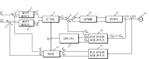
도 1은 본 발명의 실시예에 따른 단상 계통연계형 인버터의 출력제어장치의 구성을 나타낸 도면이다.1 is a view showing the configuration of an output control apparatus of a single-phase grid-connected inverter according to an embodiment of the present invention.
도 1에 도시된 바와 같이, 본 발명의 실시예에 따른 단상 계통 연계형 인버터의 출력제어장치는, 인버터(9)와 제어부를 포함한다.As shown in FIG. 1, the output control apparatus of the single-phase system-linked inverter according to the embodiment of the present invention includes an
인버터(9)는 직류링크의 양의 버스에 연결된 복수의 제1스위칭 소자 및 음의 버스에 연결된 복수의 스위칭 소자를 포함하며, 제1펄스 폭 변조신호와 제2펄스 폭 변조신호에 따라 복수의 제1스위칭 소자 및 복수의 제2스위칭 소자가 상보적으로 스위칭 동작을 하여, 소정의 직류전압을 교류전압으로 변환하여 계통(10)으로 출력한다.The
제어부는 계통전압의 기본파 성분 및 고조파 성분을 분리하여 분리된 기본파 성분을 이용하여 계통전압의 위상을 구하고, 상기 구해진 계통전압의 위상, 상기 계통전압의 고조파 성분 및 계통 지령 전압의 기본파 성분을 이용하여 제1펄스 폭 변조신호와 제2펄스 폭 변조신호를 발생해서 인버터(9)에 인가한다. 이때 계통 지령 전압은 계통(10)에 공급되는 목표 전압을 나타내며, 후술될 계통 지령 전류는 계통(10)에 공급되는 목표 전류를 나타낸다.The controller separates the fundamental and harmonic components of the grid voltage to obtain the phase of the grid voltage using the separated fundamental wave components, and calculates the phase of the obtained grid voltage, the harmonics of the grid voltage, and the fundamental wave components of the grid command voltage. The first pulse width modulated signal and the second pulse width modulated signal are generated and applied to the
이 제어부는 제1감산기(1), 제2감산기(2), 제1PI 제어기(3), 제2PI 제어기(4), 전압 정지좌표계 변환부(5), 가산기(6), 위상 변이기(7), SPWM(8), 동기좌표계 위상동기루프(Synchronous Reference Frame Phase Locked Loop: SRF PLL)(11), 전압 전차원 상태 관측기(12), 전류 동기좌표계 변환부(13) 및 전류 전차원 상태 관측기(14)를 포함한다.The control unit includes a
전압 전차원 상태 관측기(12)는 계통(10) 전압(![]()
![]()
![]()
![]()
![]()
![]()
즉, 계통(10) 전압 내 기본파 성분(![]()
![]()
![]()
![]()
![]()
![]()
![]()
![]()
![]()
![]()
![]()
![]()
![]()
![]()
![]()
![]()
SRF PLL(11)은 전압 전차원 상태 관측기(12)로부터 기본파 성분의 d축성분(![]()
![]()
![]()
![]()
![]()
![]()
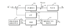
도 2에 도시된 바와 같이 SRF PLL(11)은 동기좌표계 변환부(111), 계통전압 크기 계산부(112), 저역통과필터(113), 감산기(114), PI 제어기(115), 가산기(116) 및 적분기(117)를 포함한다.As shown in FIG. 2, the SRF
동기좌표계 변환부(111)는 전압 전차원 상태 관측기(12)로부터 입력되는 계통(10) 전압의 기본파 성분의 d축성분(![]()
![]()
![]()
![]()
![]()
![]()
![]()
![]()

계통전압 크기 계산부(112)는 동기좌표계 변환부(111)에서 계통전압의 기본파 성분의 d축성분(![]()
![]()
![]()
![]()
![]()
![]()

저역통과필터(113)는 동기좌표계 변환부(111)에서 변환된 계통전압의 동기좌표계에서 기본파 성분의 q축성분(![]()
![]()
![]()
![]()
감산기(114)는 계통 지령 전압의 기본파 성분의 q축성분(
![]()

![]()
![]()
![]()
PI 제어기(115)는 계통전압 크기 계산부(112)의 출력 값인 계통전압 크기를 통해 설정된 게인(gain)을 이용하여 감산기(114)의 출력 전압 값을 비례 적분 제어하여 계통전압의 각주파수를 출력한다. 이때, PI 제어기(115)의 전달함수 T(s)는 아래의 수학식 3과 같이 모델링될 수 있다. The

이때, KP, KI는 LPF를 고려한 경우 고려하지 않은 경우에 따라 달라질 수 있다. 먼저 LPF를 고려하지 않은 경우, 
![]()
![]()
![]()
![]()
한편, LPF를 고려한 경우, 
![]()
On the other hand, if LPF is considered, ![]()
가산기(116)는 PI 제어기(115)에서 출력된 계통전압의 각주파수와 설정된 계통전압의 각주파수(![]()
![]()
적분기(116)는 가산기(116)로부터 출력된 각주파수를 적분하여 계통전압의 위상(![]()
The ![]()
다시 도 1에서, 전류 전차원 상태 관측기(14)는 계통(10) 전류(![]()
![]()
![]()
![]()
![]()
![]()
![]()
![]()
전류 동기좌표계 변환부(13)는 전류 전차원 상태 관측기(14)에서 출력된 계통전류의 기본파 성분의 d축성분(![]()
![]()
![]()
![]()
![]()
![]()
![]()
![]()

제1감산기(1)는 계통(10) 지령 전류의 기본파 성분의 q축성분(![]()
![]()
![]()
![]()
제1PI 제어기(3)는 제1감산기(1)에서 출력된 계통전류의 기본파 성분의 q축성분을 비례적분 제어하여 계통(10) 지령 전압의 기본파 성분의 q축성분(![]()
![]()
제2감산기(2)는 계통(10) 지령 전류의 기본파 성분의 d축성분(![]()
![]()
![]()
![]()
제2PI 제어기(4)는 제2감산기(2)에서 출력된 계통전류의 기본파 성분의 d축성분을 비례적분 제어하여 계통(10) 지령 전압의 기본파 성분의 d축성분(![]()
![]()
전압 정지좌표계 변환부(5)는 제1PI 제어기(3)에서 출력된 계통(10) 지령 전압의 기본파 성분의 q축성분(![]()
![]()
![]()
![]()
![]()
The voltage stop coordinate ![]()
![]()
![]()
![]()
![]()

가산기(6)는 전압 정지좌표계 변환부(5)에서 출력된 계통(10) 지령 전압의 기본파 성분의 d축성분(![]()
![]()
![]()
![]()
![]()
![]()
![]()
![]()
위상 변이기(7)는 가산기(6)에서 출력된 전압의 위상을 180도 변이 시킨다.The phase shifter 7 shifts the phase of the voltage output from the adder 6 by 180 degrees.
SPWM(8)은 가산기(6)에서 출력된 전압과 위상 변이기(7)에서 출력된 전압을 입력받아 각각에 대해서 삼각파 캐리어 신호와 비교하여 제1펄스 폭 변조신호와 제2펄스 폭 변조신호를 출력한다.
The
도 3은 본 발명의 실시예에 따른 단상 계통연계형 인버터의 출력제어장치의 신뢰성을 시뮬레이션하기 위해 구현된 시뮬레이션 시스템이다. 3 is a simulation system implemented to simulate the reliability of the output control device of the single-phase grid-connected inverter according to an embodiment of the present invention.
도 3에 도시된 바와 같이 시뮬레이션 시스템은 단상 인버터(single phase inverter), LCL-필터(filter), 전류센서(current sensor) 및 전압센서들(voltage seonsors)로 구성된다.
As shown in FIG. 3, the simulation system consists of a single phase inverter, an LCL-filter, a current sensor, and voltage seonsors.
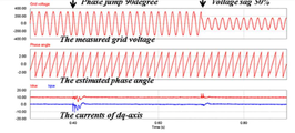
도 4a 및 도 4b는 도 1에 도시된 SRF PLL의 Voltage sag 및 위상 점프 조건들(phase jump conditions)에서 동적 특성을 나타낸 도면이다.4A and 4B are diagrams illustrating dynamic characteristics in voltage sag and phase jump conditions of the SRF PLL shown in FIG. 1.
0.4초에서 90도 만큼 위상점프가 발생하였고 0.7초에서 50%의 Voltage sag가 발생하였다. Phase jump occurred as much as 0.4 degrees at 0.4 seconds and 50% of voltage sag occurred at 0.7 seconds.
도 4a는 LPF를 사용하지 않은 경우의 동적 특성을 나타내고, 도 4b는 LPF를 사용한 경우의 동적 특성을 나타낸다. 4A shows the dynamic characteristics when no LPF is used, and FIG. 4B shows the dynamic characteristics when the LPF is used.
도 4a 및 도 4b를 비교하여 보면, 도 4b는 도 4a에 비하여 오버슈트가 75% 감소되었고 정정시간(settling time)이 대략 64% 정도 감소 되었음을 확인할 수 있다.4A and 4B, the overshoot is reduced by 75% and the settling time is reduced by about 64% compared to FIG. 4A.
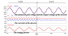
도 5a, 도 5b, 도 5c는 전차원 상태 관측기를 통해 추정된 고조파 성분에 의해 인버터의 출력전류가 보상됨을 나타낸 도면이다.5A, 5B, and 5C are diagrams illustrating that an output current of an inverter is compensated by harmonic components estimated through a full-dimensional state observer.
도 5a에는 측정된 계통 전압(the measured voltage), 인버터의 출력 전압(the output voltage), 무효성분(q축성분) 및 유효성분(d축성분) 축 상의 전류들(The currents of the dq-axis) 및 측정된 인버터의 출력전류(The output current)가 예시되어 있다.5a shows the measured voltage, the output voltage of the inverter, the currents on the reactive component (q-axis component) and the active component (d-axis component) axis. And the output current of the measured inverter are illustrated.
도 5a에 예시된 바와 같이 본 발명의 실시예에 따른 단상 계통 연계형 인버터의 출력제어장치에 의해서 보상이 이루어진 후, 인버터의 출력전류에 포함된 리플(ripple)이 줄어들었음을 확인할 수 있다.As illustrated in FIG. 5A, after compensation is performed by the output control apparatus of the single-phase grid-connected inverter according to the embodiment of the present invention, it can be confirmed that ripple included in the output current of the inverter is reduced.
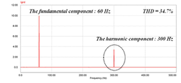
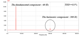
나아가 도 5b 및 도 5c는 각각 보상전 및 보상후의 인버터 출력전류에 포함된 기본파 및 고조파 성분을 나타낸 도면이다.5B and 5C are diagrams illustrating fundamental and harmonic components included in the inverter output currents before and after compensation, respectively.
도 5c는 도 5b에 비해서 인버터 출력전류의 THD(Total Harmonic Distortion)가 34.7%에서 8.5%로 감소하였음을 확인할 수 있다.
5c shows that the total harmonic distortion (THD) of the inverter output current is reduced from 34.7% to 8.5% compared to FIG. 5b.
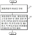
도 6은 본 발명의 실시예에 따른 단상 계통연계형 인버터의 출력제어방법에 대한 흐름도를 나타낸 도면이다.6 is a flowchart illustrating an output control method of a single-phase grid-connected inverter according to an embodiment of the present invention.
도 6에 도시된 바와 같이 단상 계통 연계형 인버터의 출력제어방법은, 직류링크의 양의 버스에 연결된 복수의 제1스위칭 소자 및 음의 버스에 연결된 복수의 스위칭 소자를 포함하며, 제1펄스 폭 변조신호와 제2펄스 폭 변조신호에 따라 복수의 제1스위칭 소자 및 복수의 제2스위칭 소자가 상보적으로 스위칭 동작을 하여, 소정의 직류전압을 교류전압으로 변환하여 계통에 제공하는 인버터의 출력을 제어하는 방법이다.As shown in FIG. 6, the output control method of the single-phase system-linked inverter includes a plurality of first switching elements connected to a positive bus of a DC link and a plurality of switching elements connected to a negative bus, and includes a first pulse width. The output of the inverter which converts a predetermined DC voltage into an AC voltage and provides it to the system by switching between the plurality of first switching elements and the plurality of second switching elements in accordance with the modulation signal and the second pulse width modulation signal. How to control it.
먼저, 계통전압의 기본파 성분 및 고조파 성분을 분리하여 분리된 기본파 성분을 이용하여 계통전압의 위상을 구한다(S1).First, the phase of the grid voltage is obtained by separating the fundamental wave component and the harmonic component of the grid voltage using the separated fundamental wave component (S1).
상기 구해진 위상, 상기 계통전압의 고조파 성분 및 계통 지령 전압의 기본파 성분을 이용하여 제1펄스 폭 변조신호와 제2펄스 폭 변조신호를 발생해서 인버터에 인가함으로써 인버터의 출력전류를 제어한다(S2).
The output current of the inverter is controlled by generating a first pulse width modulation signal and a second pulse width modulation signal using the obtained phase, the harmonic component of the grid voltage, and the fundamental wave component of the grid command voltage, and applying them to the inverter (S2). ).
이제까지 본 발명에 대하여 실시예들을 중심으로 살펴보았다. 본 발명이 속하는 기술분야에서 통상의 지식을 가진 자는 본 발명의 본질적인 특성에서 벗어나지 않는 범위에서 변형된 형태로 구현될 수 있음을 이해할 수 있을 것이다. 그러므로 개시된 실시예들은 한정적인 관점이 아니라 설명적인 관점에서 고려되어야 한다. 따라서 본 발명의 범위는 전술한 실시예에 한정되지 않고 특허청구범위에 기재된 내용 및 그와 동등한 범위 내에 있는 다양한 실시 형태가 포함되도록 해석되어야 할 것이다. The present invention has been described above with reference to the embodiments. It will be understood by those skilled in the art that various changes in form and details may be made therein without departing from the spirit and scope of the invention as defined by the appended claims. Therefore, the disclosed embodiments should be considered in an illustrative rather than a restrictive sense. Therefore, the scope of the present invention is not limited to the above-described embodiments, but should be construed to include various embodiments within the scope of the claims and equivalents thereof.
Claims (6)
계통전압의 기본파 성분 및 고조파 성분을 분리하여 분리된 기본파 성분을 이용하여 계통전압의 위상을 구하고, 상기 구해진 계통전압의 위상, 계통전압의 고조파 성분 및 계통 지령 전압의 기본파 성분을 이용하여 계통전압에서 분리된 고조파 성분의 보상을 통해 제1펄스폭 변조신호와 제2펄스폭 변조신호의 발생을 제어하여 인버터의 출력 전류에서 고조파가 제거되도록 하는 제어부를 포함하는 것을 특징으로 하는 단상 계통연계형 인버터의 출력제어장치.A plurality of first switching elements connected to the positive bus of the DC link and a plurality of switching elements connected to the negative bus, the plurality of first switching elements according to the first pulse width modulation signal and the second pulse width modulation signal; A plurality of second switching elements complementarily switch operation to convert a predetermined DC voltage into an AC voltage and provide the system to the system; Wow
The phase voltage of the grid voltage is obtained by separating the fundamental wave components and the harmonic components of the grid voltage, and the phase voltage of the grid voltage, the harmonic components of the grid voltage, and the fundamental wave components of the grid command voltage are obtained. Single phase grid connection comprising a control unit for controlling the generation of the first pulse width modulation signal and the second pulse width modulation signal by the compensation of the harmonic components separated from the grid voltage to remove harmonics from the output current of the inverter Control device of inverter type inverter.
상기 제어부는,
계통 전압 내에 포함된 기본파 성분과 고조파 성분을 이용하여 기본파 성분의 d축성분 값 및 고조파성분의 d축성분 값과 기본파 성분의 q축성분 값 및 고조파 성분의 q축성분 값을 추정하는 전압 전차원 상태 관측기;
전압 전차원 상태 관측기에서 추정된 기본파 성분의 d축성분 값과 기본파 성분의 q축성분 값을 이용하여 계통전압의 위상을 계산하여 출력하는 동기좌표계 위상동기루프;
계통 전류 내 기본파 성분을 이용하여 기본파 성분의 d축성분 값과 기본파 성분의 q축성분 값을 추정하여 출력하는 전류 전차원 상태 관측기;
전류 전차원 상태 관측기에서 출력된 계통전류의 기본파 성분의 d축성분 값과 기본파 성분의 q축성분 값을 동기 좌표계에서의 계통전류의 기본파 성분의 d축성분 값 및 기본파 성분의 q축성분 값으로 변환하는 전류 동기좌표계 변환부;
계통 지령 전류의 기본파 성분의 q축성분 값과 전류 동기좌표계 변환부에서 출력된 계통전류의 기본파 성분의 q축성분 값과의 차를 출력하는 제1감산기;
제1감산기에서 출력된 계통전류의 기본파 성분의 q축성분 값을 비례적분 제어하여 계통 지령 전압의 기본파 성분의 q축성분 값을 출력하는 제1PI 제어기;
계통 지령 전류의 기본파 성분의 d축성분 값과 전류 동기좌표계 변환부에서 출력된 계통전류의 기본파 성분의 d축성분 값의 차를 출력하는 제2감산기;
제2감산기에서 출력된 계통전류의 기본파 성분의 d축성분 값을 비례적분 제어하여 계통 지령 전압의 기본파 성분의 d축성분 값을 출력하는 제2PI 제어기;
제1PI 제어기에서 출력된 계통 지령 전압의 기본파 성분의 q축성분 값과 제2PI제어기에서 출력된 계통 지령 전압의 기본파 성분의 d축성분 값을 각각 정지 좌표계에서 계통 지령 전압의 기본파 성분의 q축성분 값과 기본파 성분의 d축성분 값으로 변환하는 전압 정지좌표계 변환부;
전압 정지좌표계 변환부에서 출력된 계통 지령 전압의 기본파 성분의 d축성분 값과 전압 전차원 상태 관측기에서 추정된 계통 전압의 고조파 성분의 d축성분 값의 합을 출력하는 가산기;
가산기에서 출력된 전압의 위상을 180도 변이 시키는 위상 변이기; 및
가산기에서 출력된 전압과 위상 변이기에서 출력된 전압을 입력받아 각각에 대해서 삼각파 캐리어 신호와 비교하여 제1펄스 폭 변조신호와 제2펄스 폭 변조신호를 출력하는 SPWM를 포함하는 것을 특징으로 하는 단상 계통연계형 인버터의 출력제어장치.The method of claim 1,
The control unit,
Estimating the d-axis component value of the fundamental wave component, the d-axis component value of the harmonic component, the q-axis component value of the fundamental wave component, and the q-axis component value of the harmonic component using the fundamental and harmonic components included in the system voltage Voltage full-dimensional state observer;
A synchronous coordinate system phase synchronizing loop for calculating and outputting a phase of a system voltage using the d-axis component value and the q-axis component value of the fundamental wave component estimated by the voltage full-dimensional state observer;
A current full-dimensional state observer for estimating the d-axis component value of the fundamental wave component and the q-axis component value of the fundamental wave component using the fundamental wave component in the system current;
The d-axis component value of the fundamental wave component of the grid current and the q-axis component value of the fundamental wave component output from the current full-dimensional state observer are determined by the d-axis component value of the fundamental wave component of the system current in the synchronous coordinate system and q of the fundamental wave component. A current synchronous coordinate system conversion unit converting the axial component value;
A first subtractor for outputting a difference between the q-axis component value of the fundamental wave component of the system command current and the q-axis component value of the fundamental wave component of the system current output from the current synchronous coordinate system converter;
A first PI controller configured to proportionally integrate the q-axis component values of the fundamental wave components of the system current output from the first subtractor to output the q-axis component values of the fundamental wave components of the system command voltage;
A second subtractor for outputting a difference between the d-axis component value of the fundamental wave component of the system command current and the d-axis component value of the fundamental wave component of the system current output from the current synchronous coordinate system converter;
A second PI controller configured to proportionally integrate the d-axis component values of the fundamental wave components of the system current output from the second subtractor to output the d-axis component values of the fundamental wave components of the system command voltage;
The q-axis component value of the fundamental wave component of the system command voltage output from the 1PI controller and the d-axis component value of the fundamental wave component of the system command voltage output from the 2PI controller are respectively determined by the fundamental wave component of the system command voltage in the stationary coordinate system. a voltage stop coordinate system for converting the value of the q-axis component and the d-axis component of the fundamental wave component ;
An adder for outputting a sum of the d-axis component value of the fundamental wave component of the system command voltage output from the voltage stop coordinate system converter and the d-axis component value of the harmonic component of the system voltage estimated by the voltage full-dimensional state observer;
A phase shifter for shifting the phase of the voltage output from the adder by 180 degrees; And
Single phase characterized in that it comprises a SPWM for receiving the voltage output from the adder and the voltage output from the phase shifter and outputs the first pulse width modulated signal and the second pulse width modulated signal for each of them compared with the triangular wave carrier signal. Output control device of grid-connected inverter.
상기 동기좌표계 위상동기루프는,
전압 전차원 상태 관측기로부터 입력되는 계통 전압의 기본파 성분의 d축성분 값과 기본파 성분의 q축성분 값을 동기좌표계에서 계통전압의 기본파 성분의 d축성분 값 및 기본파 성분의 q축성분 값으로 변환하는 동기좌표계 변환부;
상기 계통전압의 기본파 성분의 d축성분 값과 기본파 성분의 q축성분 값을 이용하여 계통전압 크기를 계산하는 계통전압 크기 계산부;
계통 지령전압의 기본파 성분의 q축성분 값과 동기좌표계 변환부에서 출력된 계통전압의 동기좌표계에서 기본파 성분의 q축성분 값 간의 차를 출력하는 감산기;
상기 계통전압 크기를 통해 설정된 게인을 이용하여 감산기의 출력 값을 비례 적분 제어하여 계통전압의 각주파수를 출력하는 PI 제어기;
PI 제어기에서 출력된 계통전압의 각주파수와 설정된 계통전압의 각주파수를 합산하는 가산기; 및
가산기에서 출력되는 각주파수를 적분하여 계통전압의 위상을 출력하는 적분기를 포함하는 것을 특징으로 하는 단상 계통연계형 인버터의 출력제어장치.The method of claim 2,
The synchronous coordinate system phase synchronization loop,
The d-axis component value of the fundamental wave component and the q-axis component value of the fundamental wave component of the grid voltage input from the voltage full-dimensional state observer are determined by the d-axis component value of the fundamental wave component of the grid voltage and the q-axis of the fundamental wave component in the synchronous coordinate system. A synchronous coordinate system conversion unit for converting the component values;
A system voltage magnitude calculator for calculating a system voltage magnitude by using a d-axis component value of the fundamental wave component of the grid voltage and a q-axis component value of the fundamental wave component;
A subtractor for outputting a difference between the q-axis component value of the fundamental wave component of the system command voltage and the q-axis component value of the fundamental wave component in the synchronous coordinate system of the system voltage output from the synchronous coordinate system converter;
A PI controller for outputting angular frequencies of the grid voltage by proportionally integral controlling the output value of the subtractor using the gain set through the grid voltage magnitude;
An adder for summing the angular frequencies of the grid voltages output from the PI controller and the angular frequencies of the set grid voltages; And
And an integrator for integrating the angular frequencies output from the adder and outputting the phase of the grid voltage.
상기 동기좌표계 위상동기루프는,
전압 전차원 상태 관측기로부터 입력되는 계통 전압의 기본파 성분의 d축성분 값과 기본파 성분의 q축성분 값을 동기좌표계에서 계통전압의 기본파 성분의 d축성분 값 및 기본파 성분의 q축성분 값으로 변환하는 동기좌표계 변환부;
상기 계통전압의 기본파 성분의 d축성분 값과 기본파 성분의 q축성분 값을 이용하여 계통전압 크기를 계산하는 계통전압 크기 계산부;
동기좌표계 변환부에서 변환된 계통전압의 동기좌표계에서 기본파 성분의 q축성분 값을 저역 통과시키는 저역통과필터;
계통 지령전압의 기본파 성분의 q축성분 값과 상기 저역통과필터의 출력 값 간의 차를 출력하는 감산기;
상기 계통전압 크기를 통해 설정된 게인을 이용하여 감산기의 출력 값을 비례 적분 제어하여 계통전압의 각주파수를 출력하는 PI 제어기;
PI 제어기에서 출력된 계통전압의 각주파수와 설정된 계통전압의 각주파수를 합산하는 가산기; 및
가산기에서 출력되는 각주파수를 적분하여 계통전압의 위상을 출력하는 적분기를 포함하는 것을 특징으로 하는 단상 계통연계형 인버터의 출력제어장치.The method of claim 2,
The synchronous coordinate system phase synchronization loop,
The d-axis component value of the fundamental wave component and the q-axis component value of the fundamental wave component of the grid voltage input from the voltage full-dimensional state observer are determined by the d-axis component value of the fundamental wave component of the grid voltage and the q-axis of the fundamental wave component in the synchronous coordinate system. A synchronous coordinate system conversion unit for converting the component values;
A system voltage magnitude calculator for calculating a system voltage magnitude by using a d-axis component value of the fundamental wave component of the grid voltage and a q-axis component value of the fundamental wave component;
A low pass filter for low-passing the q-axis component values of the fundamental wave components in the synchronous coordinate system of the system voltage converted by the synchronous coordinate system converter;
A subtractor for outputting a difference between the q-axis component value of the fundamental wave component of the system command voltage and the output value of the low pass filter;
A PI controller for outputting angular frequencies of the grid voltage by proportionally integral controlling the output value of the subtractor using the gain set through the grid voltage magnitude;
An adder for summing the angular frequencies of the grid voltages output from the PI controller and the angular frequencies of the set grid voltages; And
And an integrator for integrating the angular frequencies output from the adder and outputting the phase of the grid voltage.
상기 전압 전차원 상태 관측기는,
상기 계통 전압 내에 포함된 기본파 성분을 상기 기본파 성분의 d축성분 값으로 하고 상기 계통 전압 내에 포함된 기본파 성분의 위상을 90도 지연하여 기본파 성분의 q축성분 값으로 추정하고, 상기 계통 전압 내에 포함된 고조파 성분을 고조파 성분의 d축성분 값으로 하고 상기 계통 전압 내에 포함된 고조파 성분의 위상을 90도 지연하여 고조파 성분의 q축성분 값을 추정하는 것을 특징으로 하는 단상 계통연계형 인버터의 출력제어장치.5. The method according to any one of claims 2 to 4,
The voltage full-dimensional state observer,
The fundamental wave component included in the system voltage is the d-axis component value of the fundamental wave component, and the phase of the fundamental wave component included in the system voltage is delayed by 90 degrees to estimate the q-axis component value of the fundamental wave component. Single-phase system linkage type, characterized in that the harmonic component included in the system voltage is the d-axis component value of the harmonic component, and the q-axis component value of the harmonic component is estimated by delaying the phase of the harmonic component included in the system voltage by 90 degrees. Inverter output control device.
계통전압의 기본파 성분 및 고조파 성분을 분리하여 분리된 기본파 성분을 이용하여 계통전압의 위상을 구하는 단계; 와
상기 구해진 계통전압의 위상, 계통전압의 고조파 성분 및 계통 지령 전압의 기본파 성분을 이용하여 계통전압에서 분리된 고조파 성분의 보상을 통해 제1펄스폭 변조신호와 제2펄스폭 변조신호의 발생을 제어하여 인버터의 출력 전류에서 고조파가 제거되도록 하는 단계를 포함하는 것을 특징으로 하는 단상 계통연계형 인버터의 출력제어방법.A plurality of first switching elements connected to the positive bus of the DC link and a plurality of switching elements connected to the negative bus, the plurality of first switching elements according to the first pulse width modulation signal and the second pulse width modulation signal; In the output control method of the inverter in which a plurality of second switching elements complementary switching operation to convert a predetermined DC voltage into an AC voltage to provide to the system,
Obtaining a phase of the grid voltage using the separated fundamental wave component by separating the fundamental wave component and the harmonic component of the grid voltage; Wow
Generation of the first pulse width modulated signal and the second pulse width modulated signal by compensating the harmonic components separated from the grid voltage using the obtained phase voltage of the grid voltage, the harmonic components of the grid voltage, and the fundamental wave components of the grid command voltage. And controlling the harmonics to be removed from the output current of the inverter.
Priority Applications (1)
| Application Number | Priority Date | Filing Date | Title |
|---|---|---|---|
| KR1020110078055A KR101213333B1 (en) | 2011-08-05 | 2011-08-05 | Apparatus and method of controlling output of a single phase grid connected inverter |
Applications Claiming Priority (1)
| Application Number | Priority Date | Filing Date | Title |
|---|---|---|---|
| KR1020110078055A KR101213333B1 (en) | 2011-08-05 | 2011-08-05 | Apparatus and method of controlling output of a single phase grid connected inverter |
Publications (1)
| Publication Number | Publication Date |
|---|---|
| KR101213333B1 true KR101213333B1 (en) | 2012-12-18 |
Family
ID=47907850
Family Applications (1)
| Application Number | Title | Priority Date | Filing Date |
|---|---|---|---|
| KR1020110078055A KR101213333B1 (en) | 2011-08-05 | 2011-08-05 | Apparatus and method of controlling output of a single phase grid connected inverter |
Country Status (1)
| Country | Link |
|---|---|
| KR (1) | KR101213333B1 (en) |
Cited By (6)
| Publication number | Priority date | Publication date | Assignee | Title |
|---|---|---|---|---|
| KR101524786B1 (en) * | 2013-12-18 | 2015-06-01 | 포스코에너지 주식회사 | Method of compensating sensing-offest of grid voltage and apparatus thereof |
| KR101567054B1 (en) | 2013-12-18 | 2015-11-06 | 포스코에너지 주식회사 | Method of compensating sensing-offset of grid connected inverter and apparatus thereof |
| CN112103970A (en) * | 2020-08-26 | 2020-12-18 | 国网河南省电力公司电力科学研究院 | Method and device for suppressing inter-harmonic oscillation of grid-connected converter |
| CN112688586A (en) * | 2020-12-16 | 2021-04-20 | 河南海格经纬信息技术有限公司 | Control method for improved weighted average current of LCL grid-connected inverter |
| KR20210045087A (en) * | 2019-10-16 | 2021-04-26 | 한국전력공사 | Control apparatus of grid connected inverter |
| KR20210075448A (en) * | 2019-12-13 | 2021-06-23 | 아주대학교산학협력단 | Apparatus and method for selective harmonic compensation method for grid-connected inverter |
Citations (3)
| Publication number | Priority date | Publication date | Assignee | Title |
|---|---|---|---|---|
| US6339538B1 (en) | 1998-06-22 | 2002-01-15 | Clayton Kling Philips Handleman | Inverter circuit and method of operation |
| US6429546B1 (en) | 1998-11-20 | 2002-08-06 | Georgia Tech Research Corporation | Systems and methods for preventing islanding of grid-connected electrical power systems |
| US6949843B2 (en) | 2003-07-11 | 2005-09-27 | Morningstar, Inc. | Grid-connected power systems having back-up power sources and methods of providing back-up power in grid-connected power systems |
-
2011
- 2011-08-05 KR KR1020110078055A patent/KR101213333B1/en active IP Right Grant
Patent Citations (3)
| Publication number | Priority date | Publication date | Assignee | Title |
|---|---|---|---|---|
| US6339538B1 (en) | 1998-06-22 | 2002-01-15 | Clayton Kling Philips Handleman | Inverter circuit and method of operation |
| US6429546B1 (en) | 1998-11-20 | 2002-08-06 | Georgia Tech Research Corporation | Systems and methods for preventing islanding of grid-connected electrical power systems |
| US6949843B2 (en) | 2003-07-11 | 2005-09-27 | Morningstar, Inc. | Grid-connected power systems having back-up power sources and methods of providing back-up power in grid-connected power systems |
Non-Patent Citations (1)
| Title |
|---|
| 전력전자학회 논문집(제목: 고성능 DSP 제어기를 사용한 태양광인버터의 하모닉 추츨기법에 대한 연구), 논문발표 2010년 8월* |
Cited By (8)
| Publication number | Priority date | Publication date | Assignee | Title |
|---|---|---|---|---|
| KR101524786B1 (en) * | 2013-12-18 | 2015-06-01 | 포스코에너지 주식회사 | Method of compensating sensing-offest of grid voltage and apparatus thereof |
| KR101567054B1 (en) | 2013-12-18 | 2015-11-06 | 포스코에너지 주식회사 | Method of compensating sensing-offset of grid connected inverter and apparatus thereof |
| KR20210045087A (en) * | 2019-10-16 | 2021-04-26 | 한국전력공사 | Control apparatus of grid connected inverter |
| KR102667619B1 (en) | 2019-10-16 | 2024-05-27 | 한국전력공사 | Control apparatus of grid connected inverter |
| KR20210075448A (en) * | 2019-12-13 | 2021-06-23 | 아주대학교산학협력단 | Apparatus and method for selective harmonic compensation method for grid-connected inverter |
| KR102276105B1 (en) | 2019-12-13 | 2021-07-12 | 아주대학교산학협력단 | Apparatus and method for selective harmonic compensation method for grid-connected inverter |
| CN112103970A (en) * | 2020-08-26 | 2020-12-18 | 国网河南省电力公司电力科学研究院 | Method and device for suppressing inter-harmonic oscillation of grid-connected converter |
| CN112688586A (en) * | 2020-12-16 | 2021-04-20 | 河南海格经纬信息技术有限公司 | Control method for improved weighted average current of LCL grid-connected inverter |
Similar Documents
| Publication | Publication Date | Title |
|---|---|---|
| KR101213333B1 (en) | Apparatus and method of controlling output of a single phase grid connected inverter | |
| WO2021029313A1 (en) | System interconnection power conversion device | |
| AU2014255029B2 (en) | Control device | |
| EP2930838A2 (en) | Power converting apparatus, control device of power converting apparatus, and control method of power converting apparatus | |
| JP5062325B2 (en) | System stabilization device | |
| JP5051127B2 (en) | Power converter and control method thereof | |
| JP2009219263A (en) | Single-phase voltage type ac-dc converter | |
| KR101789403B1 (en) | Phase Error Compensation Method According to the Grid Frequency Variation of the Single-phase Grid-connected Inverters | |
| JP4935617B2 (en) | Active filter function device | |
| KR102160883B1 (en) | An apparatus of current control for harmonic compensation in grid connected inverter | |
| CN105743367A (en) | Dead beat control method of pulse width modulation (PWM) rectifier under unbalanced power grid voltage | |
| JP2018182811A (en) | Power converter and control device therefor | |
| JP6394401B2 (en) | 5-level power converter and control method | |
| KR100944266B1 (en) | A method and system for estimating phase angle | |
| US11953530B2 (en) | System frequency detector | |
| Ko et al. | A new PLL system using full order observer and PLL system modeling in a single phase grid-connected inverter | |
| KR20130021134A (en) | Apparatus for controlling current of inverter | |
| KR20200136659A (en) | Phase detecting device of system voltage | |
| KR101125111B1 (en) | Method for acquiring fundamental frequency component of phase-locked loop and phase-locked loop controller using the method | |
| JP2016015816A (en) | Controller of 5 level converter | |
| JP2005003530A (en) | Phase detector | |
| KR102182594B1 (en) | Synchronous reference frame pahse locked loop, method and system for dc offset compensation of single phase grid connected inverter | |
| US20210405098A1 (en) | System frequency detector | |
| JP2019058038A (en) | Power conversion device and power conversion system | |
| JP2018019466A (en) | Power conversion device |
Legal Events
| Date | Code | Title | Description |
|---|---|---|---|
| A201 | Request for examination | ||
| E902 | Notification of reason for refusal | ||
| E701 | Decision to grant or registration of patent right | ||
| GRNT | Written decision to grant | ||
| FPAY | Annual fee payment |
Payment date: 20151005 Year of fee payment: 4 |
|
| FPAY | Annual fee payment |
Payment date: 20161004 Year of fee payment: 5 |
|
| FPAY | Annual fee payment |
Payment date: 20171012 Year of fee payment: 6 |