KR101206502B1 - The folding bicycle use drive pedal and battery - Google Patents
The folding bicycle use drive pedal and battery Download PDFInfo
- Publication number
- KR101206502B1 KR101206502B1 KR1020100072068A KR20100072068A KR101206502B1 KR 101206502 B1 KR101206502 B1 KR 101206502B1 KR 1020100072068 A KR1020100072068 A KR 1020100072068A KR 20100072068 A KR20100072068 A KR 20100072068A KR 101206502 B1 KR101206502 B1 KR 101206502B1
- Authority
- KR
- South Korea
- Prior art keywords
- shaft
- bicycle
- handle
- saddle
- chassis
- Prior art date
Links
Images


Classifications
-
- B—PERFORMING OPERATIONS; TRANSPORTING
- B62—LAND VEHICLES FOR TRAVELLING OTHERWISE THAN ON RAILS
- B62K—CYCLES; CYCLE FRAMES; CYCLE STEERING DEVICES; RIDER-OPERATED TERMINAL CONTROLS SPECIALLY ADAPTED FOR CYCLES; CYCLE AXLE SUSPENSIONS; CYCLE SIDE-CARS, FORECARS, OR THE LIKE
- B62K15/00—Collapsible or foldable cycles
- B62K15/006—Collapsible or foldable cycles the frame being foldable
- B62K15/008—Collapsible or foldable cycles the frame being foldable foldable about 2 or more axes
-
- B—PERFORMING OPERATIONS; TRANSPORTING
- B62—LAND VEHICLES FOR TRAVELLING OTHERWISE THAN ON RAILS
- B62K—CYCLES; CYCLE FRAMES; CYCLE STEERING DEVICES; RIDER-OPERATED TERMINAL CONTROLS SPECIALLY ADAPTED FOR CYCLES; CYCLE AXLE SUSPENSIONS; CYCLE SIDE-CARS, FORECARS, OR THE LIKE
- B62K19/00—Cycle frames
- B62K19/30—Frame parts shaped to receive other cycle parts or accessories
- B62K19/36—Frame parts shaped to receive other cycle parts or accessories for attaching saddle pillars, e.g. adjustable during ride
-
- B—PERFORMING OPERATIONS; TRANSPORTING
- B62—LAND VEHICLES FOR TRAVELLING OTHERWISE THAN ON RAILS
- B62K—CYCLES; CYCLE FRAMES; CYCLE STEERING DEVICES; RIDER-OPERATED TERMINAL CONTROLS SPECIALLY ADAPTED FOR CYCLES; CYCLE AXLE SUSPENSIONS; CYCLE SIDE-CARS, FORECARS, OR THE LIKE
- B62K21/00—Steering devices
- B62K21/12—Handlebars; Handlebar stems
- B62K21/16—Handlebars; Handlebar stems having adjustable parts therein
-
- B—PERFORMING OPERATIONS; TRANSPORTING
- B62—LAND VEHICLES FOR TRAVELLING OTHERWISE THAN ON RAILS
- B62M—RIDER PROPULSION OF WHEELED VEHICLES OR SLEDGES; POWERED PROPULSION OF SLEDGES OR SINGLE-TRACK CYCLES; TRANSMISSIONS SPECIALLY ADAPTED FOR SUCH VEHICLES
- B62M6/00—Rider propulsion of wheeled vehicles with additional source of power, e.g. combustion engine or electric motor
- B62M6/80—Accessories, e.g. power sources; Arrangements thereof
- B62M6/90—Batteries
Abstract
본 발명은 이동수단과 유희용으로 사용할 수 있도록 된 접이식 자전거에 관한 것으로서, 더욱 상세하게는 핸들을 양측으로 접을 수 있 도록 중앙부에 설치된 핸들절첩 브라켓과, 자전거의 앞 차대와 뒷 차대를 연결하고 상부에 손잡이가 형성되며 양측 축상에 페달이 형성된 차대 연결부재와, 상기 차대연결부재 중앙부에 설치되어 안장의 높이를 조절하고, 자전거를 접을 수 있도록 해정 기능을 갖는 안장축 및 안장축 신축레버와, 자전거 뒷바퀴 축 일측에 설치되어 자전거 받침대를 다각으로 조절할 수 있도록 다수의 요홈을 갖는 받침대 브라켓과, 자전거의 구륜을 전기 동력에 의해 이루어질 수 있도록 뒤 차대 일측에 설치되며, 필요에 따라서 착탈 할 수 있도록 된 배터리를 포함하는 구성으로 이루어진다. 이와 같이 된 본 발명은 자전거를 운행하기 위한 동력을 수동으로 구륜하는 페달과 전기 구동수단인 배터리를 이용하여 선택적으로 운행할 수 있도록 하며, 자전거를 휴대 및 보관시에는 최소의 부피로 접을 수 있도록 하여 승용차에 간단 용이하게 적재함은 물론 버스, 전철 등의 대중교통 이용시 주변사람에게 불편을 주지 않고 안전하게 휴대할 수 있도록 함으로서 거리와 장소의 제한을 받지 않고 자유롭게 이용할 수 있도록 함을 목적으로 한 배터리 및 페달 구동용 접이식 자전거에 관한 것이다. The present invention relates to a folding bicycle that can be used for a means of transportation and amusement, and more particularly, a handle folding bracket installed at the center portion to fold the handles on both sides, and connecting the front and rear chassis of the bicycle to the upper portion. A handle is formed and a chassis connection member with pedals formed on both shafts, a saddle shaft and a saddle shaft expansion lever installed in the center of the chassis connection member to adjust the height of the saddle and to fold the bicycle, and a rear wheel of the bicycle. It is installed on one side of the shaft and has a bracket bracket with a plurality of grooves to adjust the bicycle stand in various ways, and it is installed on one side of the rear chassis so that the wheel of the bicycle can be made by electric power. It consists of a configuration that includes. The present invention as described above can be selectively operated by using a pedal that is manually driven power for driving the bicycle and a battery which is an electric driving means, so that the bicycle can be folded to a minimum volume when carrying and storing the bicycle. Battery and pedal drive for the purpose of loading easily in a passenger car, as well as allowing users to use it safely without any inconvenience to those around them when using public transportation such as buses or trains. Relates to a folding bicycle.
Description
본 발명은 이동수단과 유희용으로 사용할 수 있도록 된 접이식 자전거에 관한 것으로서, 더욱 상세하게는 자전거의 구륜을 페달과 배터리를 이용하여 동력을 선택적으로 운행할 수 있도록 하며, 휴대 및 보관시에는 최소의 부피로 접을 수 있도록 하여 승용차에 간단 용이하게 적재함은 물론 버스, 전철 등의 대중교통 이용시 주변사람에게 불편을 주지 않고 안전하게 휴대할 수 있도록 한 배터리 및 페달 구동용 접이식 자전거에 관한 것이다. The present invention relates to a folding bicycle that can be used as a means of transportation and amusement, and more particularly, to allow the wheel of the bicycle to selectively drive power using a pedal and a battery, and to minimize the volume when carrying and storing the bicycle. The present invention relates to a battery and pedal-driven folding bicycle that can be easily folded and loaded into a passenger car, as well as to be safely carried without causing inconvenience to those around them when using public transportation such as buses and trains.
최근에는 국민들의 생활 수준이 높아짐에 따라 통상의 자전거보다는 유희용 자전거와 헬스용 자전거 및 이동수단으로 사용할 수 있는 자전거가 선호되고 있는 실정이다. 따라서, 단순히 접이식 자전거보다는 이동수단의 편리성과 휴대성이 간편하게 이루어진 것을 요구하고 있으나, 현재 시중에 유통되고 있는 자전거는 차대를 반으로 접거나 차대와 핸들을 접는 구조이므로 자전거를 접는데 한계가 있어 대중교통을 이용하면서 자전거도 동시에 사용하기에는 많은 불편한 문제점이 있다.Recently, as the standard of living of the citizens increases, bicycles that can be used as recreational bicycles, fitness bicycles, and transportation vehicles are preferred to ordinary bicycles. Therefore, it is demanded that the convenience and portability of the means of transportation are made simpler than the folding bicycle, but the bicycle currently on the market is limited to folding the bicycle because it is a structure that folds the chassis in half or the chassis and the steering wheel. There are many inconveniences to use the bicycle at the same time while using traffic.
또한, 이 분야의 선행기술을 살펴보면, 공개실용신안공보 제1999-0022234호(선행기술이라함)의 "접는자전거"는 스팀(7) 중간을 고정가능한 힌지(8)로 연결하여 핸들(10)이 상하로 접히고, 크로스 바(3)를 고정가능한 힌지(4)로 연결하여 앞바퀴(6)가 좌우로 접히며, 시트 포스트(16)가 시트 튜브(1) 내에 고정가능하게 끼워져 안장(12)의 높이를 조절할 수 있도록 한 자전거에 있어서, 뒷바퀴(9)가 상하로 접힐 수 있도록 상기 시트 튜브(1)의 중간을 고정가능한 힌지(13)로 연결하고, 접혀지는 뒷바퀴(9)가 지면으로부터 떠서 지지될 수 있도록 상기 시트 튜브(1)와 뒷바퀴축(14) 사이에 설치되는 짐받이(11)의 후단을 길게 형성하며, 뒷바퀴(9)가 접혔을 때 하방으로 접으면 그 단부가 상기 시트 튜브(1) 중간의 힌지(13)를 관통하여 짐받이(11) 외면에 닿을 수 있도록 상기 시트 포스트(16)의 길이를 길게 형성하고 상기 시트 튜브(1)의 힌지(13) 중 윗쪽의 힌지 플레이트(13d)를 관통시킨 구성으로 이루어진 것이다.In addition, looking at the prior art in this field, the "folding bicycle" of the Utility Model Publication No. 1999-0022234 (referred to as prior art) is connected to the handle (10) by connecting the middle of the steam (7) with a hinge (8) It is folded up and down, the
상기 선행기술은 도1a에서 도1e의 순서로 접히도록한 것이다. 즉, 도1a의 전체적인 자전거를 도1b와 같이 짐받이가 바닥으로 가도록 뒷바퀴를 접고는 도1c와 같이 앞바퀴를 뒷바퀴 일측에 접은 후 이를 도1d및 도1e와 같이 핸들을 하향으로 축소하고 안장을 하향으로 축소하여 자전거를 접을 수 있도록 한 것이다. 이와 같이 접히는 선행기술의 자전거는 도1a,에서 도1e의 순서로 자전거를 접었을 경우에 는 높이는 작게 축소되었으나, 페달 축을 중심으로 폭이 넓어져 휴대하기에는 많은 불편이 있는 관계로 대중교통과 같이 사람이 많이 승차하는 경우에는 주변 사람들로 하여금 불편을 갖게 하는 동시에 사용자기 휴대하는 데에도 상당한 문제점이 있다. 또한 인용고안은 도1c와 같이 뒷바퀴를 절첩시켜 헬스운동을 알 수 있도록 하고 있으나 이 역시 헬스에 도움이 되지 못하고 있다. 즉, 선행기술과 같이 뒤 바퀴만을 페달로 돌리는 운동을 할 경우 바퀴가 회전되면서 원심력에 의해 스스로 회전하게 됨으로 사용자의 다리에 힘을 가하는 정도가 약하여 반복운동을 할 경우 신체가 금방 익숙해져 도움이 되지 못하는 문제점이 있다.
The prior art is to be folded in the order of Figure 1a to Figure 1e. In other words, the entire bicycle of FIG. 1A is folded to the bottom of the carrier as shown in FIG. 1B, and the front wheel is folded to one side of the rear wheel as shown in FIG. 1C, and then the handle is reduced downward as shown in FIGS. It was reduced so that the bike could be folded. The folding bicycles of the prior art are reduced in height when the bicycles are folded in the order of FIGS. 1A and 1E, but the width of the bicycle is wider around the pedal shaft, which is inconvenient to carry, and thus many people like public transportation. In the case of riding, there are significant problems in carrying the user while at the same time making people around them uncomfortable. In addition, the quotation is to fold the rear wheel as shown in Figure 1c to know the fitness exercise, but this also does not help the health. In other words, as in the prior art, when only the rear wheel is pedaled, the wheel rotates itself by centrifugal force as the wheel is rotated. There is a problem.
본 발명은 이동수단과 유희용으로 사용할 수 있도록 된 접이식 자전거에 관한 것으로 자전거를 운행하기 위한 동력을 수동으로 구륜하는 페달과 전기 구동수단인 배터리를 이용하여 선택적으로 운행할 수 있도록 하며, 자전거를 휴대 및 보관시에는 최소의 부피로 접을 수 있도록 하여 승용차에 간단 용이하게 적재함은 물론 버스, 전철 등의 대중교통 이용시 주변사람에게 불편을 주지 않고 안전하게 휴대할 수 있도록 함으로서 거리와 장소의 제한을 받지 않고 자유롭게 이용할 수 있도록 함을 목적으로 한 배터리 및 페달 구동용 접이식 자전거에 관한 것이다. The present invention relates to a folding bicycle that can be used for a means of transportation and amusement, and can be selectively operated using a pedal that manually drives power for driving a bicycle and a battery which is an electric driving means. When storing, it can be folded with a minimum volume so that it can be easily loaded into a car and can be safely carried without any inconvenience to people around when using public transportation such as buses or trains. It relates to a battery and a pedal-driven folding bike for the purpose of making it possible.
본 발명은 상기 목적을 달성하기 위하여 핸들을 양측으로 접을 수 있도록 중앙부에 설치된 핸들 절첩 브라켓과,The present invention is a handle folding bracket provided in the center portion to fold the handle to both sides to achieve the above object,
자전거의 앞 차대와 뒤 차대를 연결하고 상부에 손잡이가 형성되며 양측 축상에 페달이 형성된 차대 연결부재와,A chassis connection member which connects the front chassis and the rear chassis of the bicycle and a handle is formed on the upper side and pedals are formed on both shafts;
상기 차대 연결부재 중앙부에 설치되어 안장의 높이를 조절하고, 자전거를 접을 수 있도록 해정 기능을 갖는 안장축 및 안장축신축레버와, A saddle shaft and a saddle shaft expansion lever provided at a center portion of the chassis connecting member to adjust the height of the saddle and have a defrosting function to fold the bicycle;
자전거 뒷바퀴 축 일측에 설치되어 자전거 받침대를 다각으로 조절할 수 있도록 다수의 요홈을 갖는 받침대 브라켓과,A bracket which is installed at one side of the rear wheel shaft of the bicycle and has a plurality of grooves for adjusting the bicycle support in multiple angles,
자전거의 구륜을 전기 동력에 의해 이루어질 수 있도록 뒤 차대 일측에 설치되며, 필요에 따라서 착탈 할 수 있도록 된 배터리를 포함하는 것을 특징으로 한다.It is installed on one side of the rear chassis so that the wheel of the bicycle can be made by electric power, it is characterized in that it comprises a battery that can be removable as needed.
이와 같이 구성된 본 발 명의 자전거는 구륜하기 위한 동력을 수동에 의한 페달과 전기 에너지에 의한 배터리로 운행할 수 있도록 함으로 사용자가 자전거를 남녀노소 누구나 편리하게 사용할 수 있도록 하는 동시에, 대중교통으로 이동시 자전거를 간단 용이하게 절첩 휴대할 수 있도록 한 배터리 및 페달 구동용 접이식 자전거를 제공할 수 있도록 한 것이다. The bicycle of the present invention configured as described above can be driven by manual pedals and batteries by electric energy, so that users can use the bicycle conveniently for all ages, and at the same time, use the bicycle when traveling by public transportation. It is to provide a battery and a pedal-driven folding bike that can be easily folded and carried.
본 발명은 자전거를 간단 용이하게 접을 수 있도록 함으로 승용차 트렁크에 수납이 가능하며, 특히, 대중교통을 이용하여 여행시 간편하게 휴대하여 목적지에서 자전거를 즐길 수 있는 효과와, 자전거 운행시 바퀴를 구륜시키기 위한 동력을 페달과 배터리를 이용한 전기 구동방식을 사용자가 선택적으로 실시함으로 자전거 여행시 다리의 피로를 덜어 줌으로서 하이킹을 즐길 수 있도록 하는 동시에 어린이와 노약자가 사용할 수 있도록 용이하게 사용할 수 있는 효과가 있다. The present invention can be easily stored in the trunk of the passenger car to be able to easily fold the bicycle, in particular, to carry easily when traveling by using public transport to enjoy the bicycle at the destination, and to wheel the wheels while driving The electric drive system using the pedal and the battery is powered by the user selectively to reduce the fatigue of the foot during the bicycle trip and enjoy hiking and at the same time can be easily used by children and the elderly.
도1a 내지 도1e는 종래의 자전거를 절첩하는 순서를 나타낸 예시도.
도2는 본 발명의 자전거 전체적인 구성을 나타낸 도면 대용 사시도 사진.
도3은 본 발명의 자전거 연결구성을 나타낸 도면대용 측면도 사진.
도4는 본 발명의 자건거 배면도를 나타낸 도면대용 사진.
도5는 본 발명의 자전거를 접은 상태의 도면대용 사시도 사진.
도6a, 도6b, 도6c는 본 발명의 자전거 핸들을 순차적으로 접는 상태를 나타낸 도면대용 사진.
도7a는 본 발명의 자전거 핸들을 절첩하기 위한 핸들 절첩 브라켓과 고정레버를 나타낸 구성도.
도7b는 본 발명의 자전거핸들을 접는 상태를 나타낸 예시도.
도8a는 본 발명의 자전거 안장을 올린 상태를 나타낸 도면대용 사진.
도8b는 본 발명의 승강된 안장 축이 안장축 신축레버에 의해 지지된 상태를 나타낸 예시도.
도8c는 본 발명의 안장축이 하강되어 축소된 상태를 나타낸 도면대용 사진.
도8d는 본 발명의 안장축을 하강시키는 상태를 나타낸 예시도.
도9는 본 발명의 안장신축 레버를 탄발시키기 위한 탄발장치를 나타낸 도면 대용사진.
도10a는 본 발명의 자전거 받침대를 나타낸 도면대용 사진.
도10b는 본 발명에 따른 자전거 받침대의 받침각도를 나타낸 예시도.
도11a, 11b, 11c는 본 발명의 자전거 페달을 절첩하는 순서를 나타낸 작동 예시도.
도12는 본 발명의 자전거 뒤차대에 설치되는 배터리의 분리사시도.1A to 1E are exemplary views showing a procedure of folding a conventional bicycle.
Figure 2 is a perspective view photograph substitute drawing showing the overall configuration of the bicycle of the present invention.
Figure 3 is a side view photograph for the drawing table showing a bicycle connection configuration of the present invention.
Figure 4 is a drawing substitute photograph showing a rear view of the bicycle according to the present invention.
5 is a perspective view photograph for the drawing stand in a state of folding the bicycle of the present invention.
Figure 6a, Figure 6b, Figure 6c is a drawing substitute photo showing a state of folding the bicycle handlebar of the present invention sequentially.
Figure 7a is a block diagram showing a handle folding bracket and a fixing lever for folding the handlebar of the present invention.
Figure 7b is an exemplary view showing a state of folding the bicycle handle of the present invention.
Figure 8a is a drawing substitute photograph showing a state raised a bicycle saddle of the present invention.
Figure 8b is an illustration showing a state in which the elevated saddle shaft of the present invention is supported by the saddle shaft expansion lever.
Figure 8c is a drawing substitute photograph showing a state in which the saddle axis is reduced by reducing the present invention.
Figure 8d is an illustration showing a state of lowering the saddle shaft of the present invention.
9 is a drawing substitute photograph showing a carburizing device for firing the saddle stretch lever of the present invention.
Figure 10a is a photograph for the drawing table showing a bicycle stand of the present invention.
Figure 10b is an exemplary view showing the angle of support of the bicycle stand according to the present invention.
Figures 11a, 11b, 11c is an operation example showing the procedure of folding the bicycle pedal of the present invention.
Figure 12 is an exploded perspective view of a battery installed on the bicycle rear chassis of the present invention.
본 발명의 실시 예를 구체적으로 설명하면 다음과 같다.Hereinafter, an embodiment of the present invention will be described in detail.
휴대가 간편하도록 절첩하는 자전거에 있어서,In the bicycle which is folded for easy carrying,
양측 핸들(2)을 핸들 힌지축(6)(6') 중심으로 접을 수 있도록 핸들 축(3)에 설치된 핸들 절첩 브라켓(4)과;A handle folding bracket (4) provided at the handle shaft (3) to fold both handles (2) about the handle hinge shafts (6) (6 ');
자전거의 앞 차대(8)와 뒤 차대(9)를 연결하고 상부에 손잡이(10)가 형성되며 양측 페달 축(11) 단에 절첩될 수 있도록 페달(13)이 형성된 차대 연결부재(18)와;
상기 차대 연결부재(18) 중앙부에는 안장(19)의 높이를 조절할 수 있도록 안장축 홀(55)에 끼워진 안장축(28)과, 상기 안장축(28) 후부의 안장축 신축 레버 홀(56)에 끼워져 홀 단턱에 걸리도록 절곡부(27)가 형성된 안장 축 신축 레버(30)와, 상기 안장축(28) 상단에 설치되어 안장축 후면에 위치한 안장축 신축레버(30)의 하단 절곡부(27)가 수직선상에서 어긋난 상태를 유지하도록 하는 탄발장치(20)와; The
자전거 뒷바퀴 축(58) 일측 하단에 설치되어 자전거 받침대(40)를 여러 각도로 조절할 수 있도록 다수의 요홈(41)을 갖는 받침대 브라켓(42)과,A
자전거의 구륜을 전기 동력에 의해 이루어질 수 있도록 뒤 차대(9) 일측에 설치되며, 필요에 따라서 착탈 할 수 있도록 된 배터리(43)를 포함하는 구성을 특징으로 한다.It is installed on one side of the
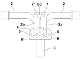
상기 핸들 절첩 브라켓(4)은 핸들 축(3) 상단에 설치되고, 상단과 양측 테두리 면에 다수의 고정홈(5)이 설치되며, 핸들(2) 중앙부에 일체로 형성된 수직부재(2a)(2b) 하단은 핸들 힌지축(6)(6')에 고정되어 양측으로 절첩될 수 있도록 하고. 핸들 힌지축(6)(6') 수직선상의 수직부재(2a)(2b) 상단에 각각의 고정레버(7)(7')가 설치되어 고정레버 하단부 돌기가 핸들 절첩 브라켓(4)의 고정홈(5) 끼워져 핸들(2)을 고정할 수 있도록 구성된 것을 특징으로 한다.The handle folding bracket (4) is installed on the top of the handle shaft (3), a plurality of fixing grooves (5) are installed on the top and both side edges, vertical member (2a) formed integrally with the center of the handle (2) ( 2b) The lower end is fixed to the handle hinge shaft (6) (6 ') so that it can be folded to both sides. Each of the
상기 앞 차대(8)는 복수로 이루어지며 차대 연결부재(18)와 핸들축(3) 사이에 위치하여 앞차대 전방 힌지축(52)과 앞차대 후방 힌지축(53)에 의해 유동되도록 설치된 구성을 특징으로 한다. The
상기 차대 연결부재는 일측에 앞 차대(8)의 일측단이 연결되도록 앞차대 후방 힌지축(53)이 형성되며, 다른 일측에는 뒤 차대(9) 일측단이 연결되도록 뒤차대 전방 힌지축(54)이 형성되며, 상단 일측에는 고정된 손잡이(10)가 형성되고, 상기 손잡이(10) 일측 중앙부에는 안장축(28)과 안장축 신축레버(30)가 승하강되도록 안장축 홀(55)과 안장축 신축레버 홀(56)이 설치된 구성을 특징으로 한다. The chassis connecting member has a front hinge
상기 앞차대는 상부차대(8a)와 하부차대(8b)로 이루어지고 상부차대(8a)와 하부차대(8b) 사이에 절첩시 유동되도록 양단이 힌지축에 연결된 연결대(57)가 설치된 구성을 특징으로 한다.The front chassis is composed of an upper chassis (8a) and the lower chassis (8b), characterized in that the connecting
상기 받침대 브라켓은 뒤바퀴 축(58) 일측 하단에 설치되며 하단테두리에 다수의 요홈(41)이 설치되어 받침대(40)를 여러 각도에서 고정할 수 있도록 구성된 것을 특징으로 한다.The pedestal bracket is installed on one side lower end of the rear wheel shaft (58) and a plurality of grooves (41) are installed on the lower edge, characterized in that configured to fix the pedestal (40) at various angles.
상기 페달은 페달축 아암(12) 단부에 페달축(11)이 직각방향으로 설치되고 상기 페달축(11) 중앙 양측에 회전축이 형성되며. 상기 회전축(14)은 발판(15)과 연결되고 발판(15)은 일측에 유동되도록 설치된 당김 레버(16)의 당김에 의해 고정핀(17)이 걸림 및 해정 되도록 하여 발판(15)의 회전축(14)을 중심으로 직각으로 절첩되도록 구성된 된 것을 특징으로 한다.The pedal is provided with a pedal shaft (11) at right angles to the end of the pedal shaft arm (12) and a rotation shaft is formed on both sides of the center of the pedal shaft (11). The rotating
상기 안장축(28) 상단에 설치되는 탄발장치(20)는 안장축(28) 상단부에 결속부재(21)가 체결되고 상기 결속부재(21) 일단과 안장축 신축레버(30) 상단에 연장되도록 형성된 연결편(22)은 제1 핀(23)으로 끼워 결합하며, 상기 제1핀(23) 일측 안장축 신축 레버(30) 상부 연결편(22) 측에 제2핀(24)으로 걸림부재(25)를 결합하고, 상기 제1 핀(23)과 제2핀(24) 상에는 스프링(26)(26')이 각각 설치되어 안장축 신축레버(30)와 걸림부재(25)를 탄발시킬 수 있도록 구성된 것을 특징으로 한다.The
상기 뒤 차대(9) 일측에 설치되는 배터리(43)는 배터리(43)를 고정하는 베이스판(44)과 전기를 공급하는 배터리(43)의 결합으로 이루어지되 배터리(43) 일측면에는 삽입홈(45)과 콘센트부(46) 및 쇠대홈(47)이 형성되고, 베이스판(44)에는 삽입홈(45)에 끼워지는 끼움부(48) 콘센트부(46)에 접속되는 플러그부(49), 키 구멍(50) 및 쇠대(51)가 형성된 것을 특징으로 한다. The
이하 본 발명을 첨부도면에 의거하여 상세히 설명하면 다음과 같다.Hereinafter, the present invention will be described in detail with reference to the accompanying drawings.
도2는 본 발명의 자전거에 대한 전체적인 구성을 나타낸 사시도이고, 도3은 본 발명의 자전거 연결구성을 나타낸 측면도이며, 도4는 본 발명의 자건거 배면도 이다.Figure 2 is a perspective view showing the overall configuration of the bicycle of the present invention, Figure 3 is a side view showing the bicycle connection configuration of the present invention, Figure 4 is a rear view of the bicycle according to the present invention.
본 발명은 전면에 앞바퀴(100)가 위치하고 후면에는 뒷바퀴(200)가 위치하며, 앞바퀴(100)와 뒷바퀴(200) 사이에는 차대 연결부재(18)에 의해 앞 차대(8)와 뒤차대(9)가 구성된다.In the present invention, the
상기 앞바퀴 축을 중심으로 상부에는 핸들 축(3)이 연결되고 핸들 축(3) 상단에는 상면과 양측면 테두리에 다수의 고정홈(5)을 갖는 핸들 절첩 브라켓(4)이 고 정되고 상기 핸들 절첩 브라켓(4)에는 중앙부에 2개의 핸들 힌지축(6)(6')을 설치하되 이의 핸들 힌지축(6)(6')에는 핸들과 일체로 형성되어 중앙부에 수직으로 형성된 구직부재(2a)(2b) 일단이 연결되며 2개의 수직부재 양측으로는 핸들이 절곡되어 연장되고 끝단에는 핸들손잡이가 형성되어 통상의 자전거와 같이 사용자가 손으로 잡을 수 있게 된다.A
이때 본 발명의 자전거 핸들은 통상의 자전거와는 다르게 핸들 축 상단과 일체로 연결되는 것이 아니라 2개의 수직부재가 핸들 절첩 브라켓(4)에 구비된 핸들 힌지축(6)(6')에 각각 일단이 연결되어 핸들을 구성한다. 즉, 본 발명의 핸들(2)은 핸들 절첩 브라켓(4)의 핸들 힌지축(6)(6')을 중심으로 접일 수 있도록 구성된다. At this time, the bicycle handle of the present invention is not connected to the upper end of the handle shaft, unlike the ordinary bicycle, but two vertical members once each of the handle hinge shaft (6) (6 ') provided in the handle folding bracket (4) It is connected to make up the handle. That is, the
상기 핸들 축(3)은 높낮이를 조절할 수 있도록 핸들축 높낮이 조절부(3')가 형성되어 있다. The
또한, 자전거 차대의 중앙부에 차대 연결부재(18)가 위치하여 앞 차대(8)의 일측단과 뒤차대(9) 일측단은 앞 차대 전방 힌지축(52)과 뒤차대 앞차대 후방 힌지축(53)에 의해 결합된다.In addition, the
상기 앞 차대(8)는 상부차대(8a)와 하부차대(8b)로 이루어지고 상부차대(8a)와 하부차대(8b) 사이에 절첩시 유동되도록 양단이 힌지축에 연결된 연결대(57)가 설치된다.The
상기 앞차대의 상부차대와 하부차대는 호(弧)의 형상으로 곡선으로 이루어져 있다.The upper and lower chassis of the front chassis is curved in the shape of an arc (弧).
또한, 차대의 중앙부에 위치하는 차대연결부는 그 단면이 "∩"형의 형상으로서 상단 일측에는 손잡이(10)가 형성되어 자전거(1)를 절첩시 손잡이를 잡고 상부로 들어 올리거나, 완전히 접힌 자전거를 휴대시 들지않고 앞뒤 바퀴가 지면에 닿도록 한 후 손잡이를 잡고 밀면 바퀴가 구륜 되므로 이동시 편리성을 갖는다.In addition, the chassis connection portion located in the center portion of the chassis, the cross-section of the "∩" shape of the top of the
또한, 상기 차대 연결부재(18) 중앙부에는 안장축(28)이 설치되고 안장축 상부에는 통상의 자전거와 같이 안장(19)이 설치된다. 또한, 상기 안장(19)은 하부에 높낮이를 조절할 수 있도록 안장높낮이 조절부(19')가 형성되어 있다In addition, the
상기 안장 축이 끼워지는 차대 연결부에는 안장 축(28)과 안장축 신축 레버(30)가 승하강되도록 안장축 홀(55)과 안장축 신축레버 홀(56)이 설치된다.A
상기 안장축 신축레버 홀(56)은 홀 중앙 내부 일측에 턱이 형성되어 안장축신축레버의 절곡부(27)가 턱에 걸리므로 안장 축(28)을 상승시 상승된 상태를 유지하도록 한다.The saddle shaft
또한, 차대 연결부재(18)는 종 방향으로 페달구동축이 설치되어 양측단에 페달 아암이 결합되고 페달구동축 일측에는 체인구동기어가 설치되어 사용시 페달을 밟으면 페달구동축(58)이 회전하면서 체인구동기어(59)를 회전시켜 뒤 바퀴(200)를 회전할 수 있게 된다.In addition, the
상기 체인구동기어(59) 후면 일측에는 모터에 의해 회전되는 전동체인기어가 설치되어 배터리(43)의 전원에 의해 모터가 전동체인기어를 회전시켜 뒷바퀴를 구동할 수 있게 된다. 상기 배터리의 전원을 이용하여 전동체인기어(60)의 모터를 작동시에는 사용자가 핸들 일측 말단에 형성된 핸들(2)손잡이를 앞으로 회전시키지 않은 상태에서는 전원이 단락되어 모터가 작동하지 않으나, 핸들 손잡이를 앞으로 회전시킬 수 있도록 모터회전을 가속화시키므로 모터와 연결된 전동체인기어의 회전이 빨라져 이와 연결된 체인에 의해 뒷바퀴의 회전속도를 증가할 수 있게 된다. One side of the
또한, 차대연결부재의 후단 힌지축과 앞 차대의 하부차대 하단일측 힌지축에는 힌지부재(61)가 연결되어 자전거(1)를 절첩시 하부차대(2b)와 뒤 차대(9)를 비롯한 차대 연결부재(4)가 밀착되도록 당기는 역할을 한다. In addition, the
도5는 본 발명의 자전거를 접은 상태의 사시도로서, 본 발명의 자전거를 타고 가다가 대중교통을 이용시 또는 승용차의 트렁크에 수납하기 위해 자전거를 접은 상태이다.5 is a perspective view of a state in which the bicycle of the present invention is folded, while the bicycle of the present invention is folded while being used for public transportation or to be stored in the trunk of a passenger car.
또한, 도6a, 도6b, 도6c는 본 발명의 자전거 핸들을 순차적으로 접는 상태를 나타낸 것이며, 도7a는 본 발명의 자전거 핸들을 절첩하기 위한 핸들절첩 브라켓과 고정레버를 나타낸 구성도이고, 도7b는 본 발명의 자전거핸들을 접는 상태를 나타낸 것으로서 본 발명의 자전거를 도5와 같이 절첩하기 위해서는 도6a 부터 도7b까지 순차적으로 설명한다.6A, 6B, and 6C show a state in which the bicycle handlebars of the present invention are sequentially folded, and FIG. 7A is a configuration diagram showing a handle folding bracket and a fixing lever for folding the bicycle handlebar of the present invention. 7B illustrates a folding state of the bicycle handle of the present invention. In order to fold the bicycle of the present invention as shown in FIG. 5, FIGS. 6A to 7B will be described sequentially.
본 발명의 자전거는 도2와 같이 펼쳐진상태에서 도5와 같이 자전거를 접을 때는 도6a 및 7a와 같이 핸들(2)이 펼쳐진 상태에서 핸들 절첩브라켓(4)의 핸들 힌지축(6)(6')과 연결된 일측 핸들 수직부재(2a) 상단에 형성된 고정레버(7)를 상부로 당기면 핸들 절첩브라켓(4)의 상부 고정홈(5)에 걸려있던 걸림돌기(도시없음)가 이탈되면서 핸들 힌지축(6)을 중심으로 도6b와 같이 하향으로 절첩된다. 이와 같은 방법으로 다른 일측의 핸들 수직부재(2b) 상단에 형성된 고정레버(7')를 상부로 당기면 핸들 절첩브라켓(4)의 고정홈(1)에 걸려있던 걸림돌기가 이탈되면서 다른 측의 핸들 역시 하향으로 절첩할 수 있게 됨으로 본 발명의 자전거 핸들은 도6c와 같이 양측을 모두 접을 수 있게 된다.When the bicycle of the present invention is folded as shown in FIG. 5 in the unfolded state as shown in FIG. 2, the
본 발명의 자전거 핸들의 수직부재(2a)와 핸들 수직부재(2b) 사이의 상단에는 실리콘수지로된 돌기(80)가 대응되도록 형성되어 핸들 수직부재(2a)와 핸들 수직부재(2b)가 직접 맞닿는 것을 방지한다. 즉, 핸들 수직부재는 금속으로 이루어져 핸들 수직부재와 핸들 수직부재가 대응되는 사이가 밀착되어 서로 맞닿는 것을 방지하기 위해 각각의 핸들 수직부재 내측에 서로 대응되는 위치에 합성수지 돌기(80)를 설치한 것이다.The upper end between the vertical member (2a) and the handle vertical member (2b) of the bicycle handle of the present invention is formed to correspond to the projection (80) made of silicone resin so that the handle vertical member (2a) and the handle vertical member (2b) directly Prevent contact. That is, the handle vertical member is made of metal, and the
본 발명의 도 7b는 핸들을 절첩하기 위한 작동상태도를 도면으로 도시한 것이다.Figure 7b of the present invention shows a diagram showing the operating state for folding the handle.
본 발명의 자전거 핸들이 도6c와 도7b와 같이 절첩된 상태에서는 고정레버와 연결된 타단에 형성된 걸림돌기는 핸들 절첩브라켓(4)의 테두리 양측에 형성된 고정홈(5)에 인입된 상태이므로 고정레버(7)(7')를 당기기 전까지는 임으로 핸들이 펼쳐지지 않는다. 6c and 7b in the folded state as shown in Figure 6c and 7b, the locking projection formed at the other end connected to the fixing lever is inserted into the fixing
도8a는 본 발명의 자전거 안장을 올린 상태를 나타낸 것이며, 도8b는 본 발명의 승강된 안장축(28)이 안장축 신축레버(30)에 의해 지지된 상태를 나타낸 예시도이며, 도8c는 본 발명의 안장축(28)이 하강되어 축소된 상태를 나타낸 것이며, 도8d는 본 발명의 안장축을 하강시키는 상태를 나타낸 예시도이며, 도9는 본 발명의 안장신축레버를 탄발시키기 위한 탄발장치(20)를 나타낸 것이다.Figure 8a shows a state in which the bicycle saddle of the present invention is raised, Figure 8b is an exemplary view showing a state in which the
이를 구체적으로 설명하면 안장축(28) 상단에 설치된 탄발장치(20)는 안장축 후면에 위치한 안장축 신축레버(30)의 하단 절곡부(27)가 항상 수직선상에서 어긋난 상태를 유지하도록 탄발상태를 유지한다.In detail, the
즉, 안장축을 도8a와 같이 승강시킨 상태에서는 도8b에 도시된 바와 같이 안장축 신축레버 하단의 절곡부(27)가 어긋난 상태에서 안장축 신축 레버 홀(56)에 끼워져 안장축 신축 레버 홀(56) 내부 단턱에 걸쳐진 상태가 되므로 안장축은 승강된 상태에서 사용자가 안장에 올라 앉자 있더라도 하강되지 않고 지지 된다.That is, in the state in which the saddle shaft is lifted as shown in FIG. 8A, as shown in FIG. 8B, the
이때 자전거를 접기거나, 안장을 하강시키기 위해서는 안장축 신축 레버(30)를 안장축(28)측으로 당기면 절곡부(27)가 홀의 단턱에서 이탈되므로 안장축(28)과 안장축 신축레버(30)는 각각 안장축 홀(55)과 안장축 신축레버 홀(56)의 안내에 따라서 하강됨으로 접을 수 있게 된다. At this time, in order to fold the bicycle or lower the saddle, when the saddle
이와 같이 안장을 낮춤 상태에서 차대 연결부재 일측 상부에 설치된 손잡이를 잡고 상부로 들어올리면 차대 연결부재 양측에 설치된 앞차대 후방 힌지축과 뒤차대 전방 힌지축을 중심으로 앞 차대와 뒤 차대가 차대 연결부재를 중심으로 하향되어 절첩된다.In this way, when the saddle is lowered and the handle installed on the upper side of the chassis connecting member is grasped and lifted to the upper side, the front chassis and the rear chassis focus on the front chassis rear hinge shaft and the rear chassis front hinge shaft installed on both sides of the chassis coupling member. It is folded downward to the center.
이때 앞차대 전방 힌지축에 의해 앞바퀴와 핸들축이 접히고, 앞차대의 상부차대와 하부차대 사이에 설치된 연결대(57)는 상부치대(8a)와 하부차대(8b)를 당겨 밀착시키는 역할을 한다. 이와 같이 자전거를 접었을 때는 도5와 같은 형상으로 절첩된다.In this case, the front wheel and the handle shaft are folded by the front hinge shaft of the front chassis, and the connecting
이렇게 절첩된 본원발명의 자전기는 높이와 길이가 축소되어 승용차 트렁크 또는 실내에 간단 용이하게 수납할 수 있는 동시에 대중교통을 이용시 휴대하고 승차하더라도 함께 승차한 승객에게 불편을 최소화할 수 있다.The folding magnet of the present invention is reduced in height and length so that it can be easily stored in the trunk of a passenger car or indoors, and at the same time, it is possible to minimize inconvenience to passengers who ride with them even when using a public transport.
본 발명의 탄발장치(20)는 안장축(28) 상단부에 결속부재(21)가 체결되고 상기 결속부재(21) 일단과 안장축 신축레버(30) 상단에 연장되어 형성된 연결편(22)은 제1 핀(23)으로 끼워 결합하며, 상기 제1핀(23) 일측 안장축 신축 레버(30) 상부 연결편(22) 측에 제2핀(24)으로 걸림부재(25)를 결합하고, 상기 제1 핀(23)과 제2핀(24) 상에는 스프링(26)(26')이 각각 설치되어 안장축 신축레버(30)와 걸림부재(25)를 탄발시킬 수 있도록 한다.Coupling
상기 걸림부재는 본 발명의 자전거를 접을 을 경우 차대 연결부재(18)의 뒤차대 전방 힌지축(52)과 연결된 뒤차대 단부가 탄발장치의 걸림부재(25)에 걸려 접힌 상태를 유지하게 된다. 이때 자전거(1)을 펼치고자 할 경우에는 손잡이(10)을 이용하여 위로 올리면 안장축(28)과 안장축 신축레버(30)가 상승되면서 탄발장치(20)의 걸림부재(25)가 뒤차대 단부와의 지지된 상태를 해재 함으로 자전거는 다시 펼쳐져 통상의 자전거와 같은 형상으로 복귀하게 된다. When the locking member is folded, the rear chassis end connected to the rear chassis
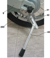
도10a는 본 발명의 자전거 받침대를 나타낸 것이며, 도10b는 본 발명에 따른 자전거 받침대의 받침각도를 나타낸 예시도이다.Figure 10a shows a bicycle support of the present invention, Figure 10b is an exemplary view showing the angle of support of the bicycle support according to the invention.
본 발명의 받침대는 뒤 바퀴 축 하부에 설치되어 자전거를 세울 수 있도록 하는 것으로서, 받침대는 뒷바퀴 축(58) 일측 하단에 받침대 브라켓(42)을 설치하여 받침대 브라켓(42)의 축을 중심으로 받침대(40)가 회전하도록 설치되며 상기 받침대 브라켓 하단테두리에는 다수의 요홈(41)이 설치되어 받침대(40)를 여러 각도에서 고정할 수 있도록 한다.The pedestal of the present invention is to be installed under the rear wheel shaft to stand the bicycle, the pedestal is a
도11a, 11b, 11c는 본 발명의 자전거 페달을 절첩하는 순서를 나타낸 작동 예시도로서, 페달(13)은 페달축 아암(12) 단부에 페달 축(11)이 직각방향으로 설치되고 상기 페달 축(11)중앙 양측에 회전축(14)이 형성되며. 상기 회전축은 발판(15)과 연결되고 발판(15)은 일측에 유동되도록 설치된 당김 레버(16)의 당김에 의해 고정핀(17)이 걸림 및 해정되도록 하여 발판의 회전축(14)을 중심으로 절첩되도록 한다.11A, 11B, and 11C are exemplary views showing the procedure of folding the bicycle pedal according to the present invention. The
즉, 도11a는 자전거를 사용시 페달이 페달축 아암과 직각방향으로 설치된 상태로서 사용자가 자전거를 구륜할 수 있도록 한다. That is, FIG. 11A shows a state in which a pedal is installed at a right angle with the pedal shaft arm when the bicycle is used, so that the user can wheel the bicycle.
상기와 같이 자전거를 사용한 후 자전거를 접을 때 페달 내측의 당김 레버를 외향으로 당기면 페달 축(11)과 발판(15)을 고정한 고정핀(17)이 페달 축과의 걸림상태를 도11b와 같이 해제됨으로 발판은 페달축 양측에서 발판과 연결된 회전축(14)을 중심으로 페달 축을 중심으로 도11c와 같이 직각방향으로 절첩할 수 있다. When using the bicycle as described above, when the bicycle is folded, the pull lever inside the pedal is pulled outward to release the locking
도12는 본 발명의 자전거 뒤차대에 설치되는 배터리의 분리사시도로서, 상기 뒤차대 일측에 설치되는 배터리는, 배터리를 고정하는 베이스판을 차대 일측에 설치하고, 배터리리와 베이스판을 결합하여 전원이 접지되도록 한다.12 is an exploded perspective view of a battery installed in a bicycle rear chassis of the present invention, the battery is installed on one side of the rear chassis, the base plate for fixing the battery is installed on one side of the chassis, the battery and the base plate combined power Make sure that it is grounded.
상기 베이스판(44)은 일측에 전선이 연결되고 이의 전선은 전동 체인기어(60)를 구동시키는 모터와 연결되고 모터는 속도를 조절하는 자전거 핸들 손잡이와 연결되어 자전거의 구륜속도를 제어할 수 있게 된다. The
상기와 같이 차대에 설치된 베이스판은 다수의 접속단자로 이루어진 플러그부(49)와 끼움부(48)로 이루어지며, 이의 끼움부(48)는 배터리(43)의 삽입홈(45)에 끼 워져 배터리가 베이스판에 결합되고, 베이스판의 플러그부(49)는 배터리의 콘센트부(46)와 접속되어 전원이 도통 된다. 이때 끼움부(48)의 하단에는 패킹(70)이 형성되어 베이스판(44)과 배터리(43)의 연결부를 통하여 물이 유입되는 것을 차단하여 전원이 방전되거나 사용자가 자전거를 탈 때 빗물이나 기타 물에 의해 감전되는 것을 방지토록 하였다.Base plate installed on the chassis as described above is composed of a
또한, 본 발명의 배터리는 일측면에 키에 의한 잠금장치가 설치되어 키 구멍(50)으로 키를 넣고 돌리면 베이스판의 쇠대(51)가 돌출되어 배터리의 쇠대홈(47)에 끼워져 베이스판과 배터리가 분리되는 것을 방지하여 도난을 예방할 수 있도록하였다.In addition, the battery of the present invention is provided with a locking device by a key on one side, the key is inserted into the
이와 같이 된 본 발명은 이동수단으로 활용하는 자전거를 페달에 의한 구륜과 배터리의 전원을 이용한 모터에 의해 구륜으로 자전거를 구동시 킬 수 있도록 함으로 사용자가 전동과 페달을 선택적 사용할 수 있다. The present invention as described above allows the user to selectively use the electric and the pedal by allowing the bicycle to be used as a driving means to drive the bicycle by the wheel by the motor using the wheel and the battery powered by the pedal.
또한, 본 발명은 자전거를 간단 용이하게 절첩하여 휴대할 수 있도록 함으로 이동수단을 자전거 및 대중교통을 복합적으로 사용할 수 있는 특징이 있다. In addition, the present invention has a feature that can be used in combination with the bicycle and public transport as a means of transporting the bicycle simply and easily folded.
1:자전거 2:핸들
2a,2b:수직부재 3:핸들축
4:핸들 절첩 브라켓 5:고정홈
6.6':핸들 힌지축 7,7':고정레버
8:앞차대 8a:상부차대
8b:하부차대 9:뒤차대
10:손잡이 11:페달축
12:페달축 아암 13:페달
14:회전축 15:안장축 홀
16:당김레버 17:고정핀
18:차대 연결부재 19:안장
20:탄발장치 21:결속부재
22:연결편 23:제1핀
24:제2핀 25:걸림부재
26, 26':스프링 27:절곡부
28:안장축 30:안장축 신축레버
40:자전거받침대 42:받침대 브라켓
43:배터리 44:베이스판
50:키구멍 51:쇠대
52:앞차대 전방힌지축 53:앞차대 후방 힌지축
54:뒤치대 전방 힌지축 55:안장축 홀
56:안장축 신축레버 홀 57:연결대
58:페달 구동축 59:체인구동기어
60:전동체인기어 61:힌지부재
70:패킹 100:앞바퀴
200:뒤바퀴1: bicycle 2: handle
2a, 2b: vertical member 3: handle shaft
4: Handle folding bracket 5: Locking groove
6.6 ':
8:
8b: Undercarriage 9: Rear Undercarriage
10: Handle 11: pedal shaft
12: Pedal axis arm 13: Pedal
14: rotating shaft 15: saddle shaft hole
16: Pull lever 17: Locking pin
18: chassis connecting member 19: saddle
20: bullet device 21: binding member
22: connecting piece 23: first pin
24: second pin 25: locking member
26, 26 ': Spring 27: Bends
28: saddle shaft 30: saddle shaft expansion lever
40: bicycle support 42: support bracket
43: battery 44: base plate
50: keyhole 51: iron rod
52: front chassis rear hinge shaft 53: front chassis rear hinge shaft
54: rear hinge front hinge shaft 55: saddle shaft hole
56: saddle shaft expansion lever hole 57: connecting rod
58: pedal drive shaft 59: chain drive gear
60: electric chain gear 61: hinge member
70: packing 100: front wheel
200: rear wheel
Claims (8)
양측 핸들(2)을 핸들 힌지축(6)(6') 중심으로 접을 수 있도록 핸들축(3)에 설치된 핸들 절첩 브라켓(4)과;
자전거의 앞차대(8)와 뒤차 대(9)를 연결하고 상부에 손잡이(10)가 형성되며 양측 페달 축(11) 단에 절첩될 수 있도록 페달(13)이 형성된 차대 연결부재(18)와;
상기 차대 연결부재(18) 중앙부에는 안장(19)의 높이를 조절할 수 있도록 안장축 홀(55)에 끼워진 안장축(28) 및 상기 안장축(28) 후부의 안장축 신축 레버 홀(56)에 끼워져 홀 단턱에 걸리도록 절곡부(27)가 형성된 안장 축 신축 레버(30)와;
상기 안장축(28) 상단에 설치되어 안장축 후면에 위치한 안장축 신축레버(30)의 하단 절곡부(27)가 수직선상에서 어긋난 상태를 유지하도록 하는 탄발장치(20)와;
자전거 뒷바퀴 축(58) 일측 하단에 설치되어 자전거 받침대(40)를 여러 각도로 조절할 수 있도록 다수의 요홈(41)을 갖는 받침대 브라켓(42)과,
자전거의 구륜을 전기 동력에 의해 이루어질 수 있도록 뒤 차대(9) 일측에 착탈 가능하도록 설치된 배터리(43)를 포함하는 구성을 특징으로 하는 배터리 및 페달 구동용 접이식 자전거.In the bicycle which is folded for easy carrying,
A handle folding bracket (4) provided at the handle shaft (3) to fold both handles (2) about the handle hinge shafts (6) (6 ');
Undercarriage connecting member (18) having a pedal (13) formed so as to connect the front chassis (8) and the rear vehicle (9) of the bicycle, and the handle (10) is formed at the upper side and can be folded at both ends of the pedal shaft (11). ;
The saddle shaft 28 fitted to the saddle shaft hole 55 and the saddle shaft telescopic lever hole 56 at the rear of the saddle shaft 28 are provided at the center portion of the chassis connecting member 18 to adjust the height of the saddle 19. A saddle shaft expansion and contraction lever (30) formed with a bent portion (27) fitted to be fitted over the hole step;
A ballistic device (20) installed at the top of the saddle shaft (28) to keep the lower bent portion (27) of the saddle shaft telescopic lever (30) positioned at the rear of the saddle shaft (28) on a vertical line;
A bracket bracket 42 having a plurality of grooves 41 to be installed at a lower side of the bicycle rear wheel shaft 58 so as to adjust the bicycle support 40 at various angles;
Battery and pedal-driven folding bike, characterized in that it comprises a battery (43) installed detachably on one side of the rear chassis (9) so that the wheels of the bicycle can be made by electric power.
상기 핸들 절첩 브라켓(4)은 핸들축(3) 상단에 설치되고, 상단과 양측 테두리 면에 다수의 고정홈(5)이 설치되며, 핸들(2) 중앙부에 일체로 형성된 수직부재(2a)(2b) 하단은 핸들 힌지축(6)(6')에 고정되어 양측으로 절첩될 수 있도록 하고. 핸들 힌지축(6)(6') 수직선상의 수직부재(2a)(2b) 상단에 각각의 고정레버(7)(7')가 설치되어 고정레버 하단부 돌기가 핸들 절첩 브라켓(4)의 고정홈(5) 끼워져 핸들(2)을 고정할 수 있도록 구성된 것을 특징으로 하는 배터리 및 페달 구동용 접이식 자전거.The method of claim 1,
The handle folding bracket (4) is installed on the top of the handle shaft (3), a plurality of fixing grooves (5) are installed on the top and both side edges, vertical member (2a) formed integrally with the center of the handle (2) ( 2b) The lower end is fixed to the handle hinge shaft (6) (6 ') so that it can be folded to both sides. Each of the fixing levers 7 and 7 'is installed on the top of the vertical members 2a and 2b on the handle hinge shafts 6 and 6' so that the lower end projection of the fixing lever is fixed to the handle folding bracket 4. (5) The folding bicycle for battery and pedal drive, characterized in that configured to be fixed to the handle (2).
상기 앞 차대(8)는 복수로 이루어지며 차대 연결부재(18)와 핸들축(3) 사이에 위치하여 앞차대 전방 힌지축(52)과 앞차대 후방 힌지축(53)에 의해 유동되도록 설치된 구성을 특징으로 하는 배터리 및 페달 구동용 접이식 자전거.The method of claim 1,
The front chassis 8 is formed in plural and positioned between the chassis connecting member 18 and the handle shaft 3 and installed to flow by the front chassis front hinge shaft 52 and the front chassis rear hinge shaft 53. Battery and pedal driven folding bike, characterized in that.
상기 차대 연결부재는 일측에 앞차대(8)의 일측단이 연결되도록 앞차대 후방 힌지축(53)이 형성되며, 다른 일측에는 뒤 차대(9) 일측단이 연결되도록 뒤차대 전방 힌지축(54)이 형성되며, 상단 일측에는 고정된 손잡이(10)가 형성되고, 상기 손잡이(10) 일측 중앙부에는 안장 축(28)과 안장축 신축레버(30)가 승하강되도록 안장축 홀(55)과 안장축 신축레버 홀(56)이 설치된 구성을 특징으로 하는 배터리 및 페달 구동용 접이식 자전거. The method of claim 1,
The chassis connecting member has a front hinge rear hinge shaft 53 is formed so that one side end of the front chassis 8 is connected to one side, the rear chassis front hinge shaft 54 so that one side end of the rear chassis 9 is connected to the other side. ) Is formed, and a fixed handle 10 is formed at one side of the upper end, and the saddle shaft hole 55 and the saddle shaft 28 and the saddle shaft expansion lever 30 are raised and lowered at one central portion of the handle 10. Folding bicycle for battery and pedal drive, characterized in that the saddle shaft expansion lever hole 56 is installed.
상기 받침대 브라켓은 뒤바퀴 축(58) 일측 하단에 설치되며 하단테두리에 다수의 요홈(41)이 설치되어 받침대(40)를 여러 각도에서 고정할 수 있도록 구성된 것을 특징으로 하는 배터리 및 페달 구동용 접이식 자전거.The method of claim 1, wherein
The pedestal bracket is installed at the bottom of one side of the rear wheel shaft (58) and a plurality of grooves (41) is installed on the bottom border is configured for folding the battery and pedal drive, characterized in that configured to fix the pedestal (40) at various angles bicycle.
상기 페달은 페달축 아암(12) 단부에 페달축(11)이 직각방향으로 설치되고 상기 페달축(11) 중앙 양측에 회전축이 형성되며, 상기 회전축(14)은 발판(15)과 연결되고 발판(15)은 일측에 유동되도록 설치된 당김 레버(16)의 당김에 의해 고정핀(17)이 걸림 및 해정되도록 하여 발판(15)의 회전축(14)을 중심으로 직각으로 절첩되도록 구성된 된 것을 특징으로 배터리 및 페달 구동용 접이식 자전거.The method of claim 1,
The pedal has a pedal shaft 11 at the end of the pedal shaft arm 12 is installed at a right angle and a rotation shaft is formed on both sides of the center of the pedal shaft 11, and the rotation shaft 14 is connected to the footrest 15 and is a footrest. 15 is configured to be folded at a right angle about the rotation axis 14 of the footrest 15 by the locking pin 17 is locked and released by the pull of the pull lever 16 installed to flow on one side. Folding bike for battery and pedal drive.
상기 안장축(28) 상단에 설치되는 탄발장치(20)는 안장축(28) 상단부에 결속부재(21)가 체결되고 상기 결속부재(21) 일단과 안장축 신축레버(30) 상단에 연장되어 형성된 연결편(22)은 제1 핀(23)으로 끼워 결합하며, 상기 제1핀(23) 일측 안장축 신축 레버(30) 상부 연결편(22) 측에 제2핀(24)으로 걸림부재(25)를 결합하고, 상기 제1 핀(23)과 제2핀(24) 상에는 스프링(26)(26')이 각각 설치되어 안장축 신축레버(30)와 걸림부재(25)를 탄발시킬 수 있도록 구성된 것을 특징으로 하는 배터리 및 페달 구동용 접이식 자전거.The method of claim 1,
The ballistic device 20 installed on the top of the saddle shaft 28 is the binding member 21 is fastened to the upper end of the saddle shaft 28 and extends at one end of the binding member 21 and the top of the saddle shaft expansion lever 30. The connecting piece 22 is fitted into the first pin 23 to be coupled to each other, and the first pin 23 on one side of the saddle shaft telescopic lever 30 is connected to the upper connecting piece 22 by the second pin 24. ), And springs 26 and 26 'are respectively installed on the first pin 23 and the second pin 24 so that the saddle shaft telescopic lever 30 and the locking member 25 can be elasticized. Battery and pedal driven folding bike, characterized in that configured.
상기 뒤차대(9) 일측에 설치되는 배터리(43)는 배터리(43)를 고정하는 베이스판(44)와 전기를 공급하는 배터리(43)의 결합으로 이루어지되 배터리(43) 일측면에는 삽입홈(45)과 콘센트부(46) 및 쇠대 홈(47)이 형성되고, 베이스판(44)에는 삽입홈(45)에 끼워지는 끼움부(48)와 콘센트부(46)에 접속되는 플러그부(49), 키 구멍(50) 및 쇠대(51)가 형성된 것을 특징으로 하는 배터리 및 페달 구동용 접이식 자전거. The method of claim 1,
The battery 43 installed on one side of the rear chassis 9 is made of a combination of a base plate 44 for fixing the battery 43 and a battery 43 for supplying electricity, but an insertion groove is formed at one side of the battery 43. 45, an outlet portion 46, and a metal rod groove 47 are formed, and the base plate 44 has a fitting portion 48 fitted into the insertion groove 45 and a plug portion connected to the outlet portion 46 ( 49), the key hole 50 and the metal pole 51 is formed, characterized in that the battery and pedal drive folding bike.
Priority Applications (1)
| Application Number | Priority Date | Filing Date | Title |
|---|---|---|---|
| KR1020100072068A KR101206502B1 (en) | 2010-07-26 | 2010-07-26 | The folding bicycle use drive pedal and battery |
Applications Claiming Priority (1)
| Application Number | Priority Date | Filing Date | Title |
|---|---|---|---|
| KR1020100072068A KR101206502B1 (en) | 2010-07-26 | 2010-07-26 | The folding bicycle use drive pedal and battery |
Publications (2)
| Publication Number | Publication Date |
|---|---|
| KR20120010487A KR20120010487A (en) | 2012-02-03 |
| KR101206502B1 true KR101206502B1 (en) | 2012-11-29 |
Family
ID=45834970
Family Applications (1)
| Application Number | Title | Priority Date | Filing Date |
|---|---|---|---|
| KR1020100072068A KR101206502B1 (en) | 2010-07-26 | 2010-07-26 | The folding bicycle use drive pedal and battery |
Country Status (1)
| Country | Link |
|---|---|
| KR (1) | KR101206502B1 (en) |
Cited By (1)
| Publication number | Priority date | Publication date | Assignee | Title |
|---|---|---|---|---|
| WO2016114582A1 (en) * | 2015-01-16 | 2016-07-21 | 강효웅 | Functional bicycle handlebar |
Families Citing this family (8)
| Publication number | Priority date | Publication date | Assignee | Title |
|---|---|---|---|---|
| CN102673704A (en) * | 2012-06-13 | 2012-09-19 | 青岛大学 | Double-driving folding pedal bicycle |
| KR101453995B1 (en) * | 2012-12-03 | 2014-10-28 | 김미나 | Folding type bicycle |
| CN106515917B (en) * | 2016-11-28 | 2019-04-19 | 苏州速蝶科技有限公司 | A kind of folding bike foldable type saddle |
| CN109665016B (en) * | 2018-12-27 | 2023-11-24 | 广东广天机电工业研究院有限公司 | Folding bicycle |
| CN110395345A (en) * | 2019-08-16 | 2019-11-01 | 刘持平 | A kind of frame structure Laggage-type folding bicycle |
| CN111086581A (en) * | 2020-01-09 | 2020-05-01 | 太仓市车中宝休闲用品有限公司 | Portable folding bicycle |
| KR102383629B1 (en) * | 2020-12-21 | 2022-04-08 | 주식회사 이엠이코리아 | Folding type electric bicycles |
| WO2022242208A1 (en) * | 2021-05-19 | 2022-11-24 | 邱树元 | Folding linkage bicycle frame |
Citations (4)
| Publication number | Priority date | Publication date | Assignee | Title |
|---|---|---|---|---|
| US20040032110A1 (en) | 2000-12-27 | 2004-02-19 | Henri Bigot | Folding bicycle |
| CN201151448Y (en) | 2007-11-21 | 2008-11-19 | 好孩子儿童用品有限公司 | Foldable bicycle |
| CN201161669Y (en) | 2008-02-28 | 2008-12-10 | 刘青 | Folding type lithium cell electric bicycle |
| CN101367415A (en) | 2007-08-13 | 2009-02-18 | 好孩子儿童用品有限公司 | Foot rest of foldable bicycle |
-
2010
- 2010-07-26 KR KR1020100072068A patent/KR101206502B1/en active IP Right Grant
Patent Citations (4)
| Publication number | Priority date | Publication date | Assignee | Title |
|---|---|---|---|---|
| US20040032110A1 (en) | 2000-12-27 | 2004-02-19 | Henri Bigot | Folding bicycle |
| CN101367415A (en) | 2007-08-13 | 2009-02-18 | 好孩子儿童用品有限公司 | Foot rest of foldable bicycle |
| CN201151448Y (en) | 2007-11-21 | 2008-11-19 | 好孩子儿童用品有限公司 | Foldable bicycle |
| CN201161669Y (en) | 2008-02-28 | 2008-12-10 | 刘青 | Folding type lithium cell electric bicycle |
Cited By (1)
| Publication number | Priority date | Publication date | Assignee | Title |
|---|---|---|---|---|
| WO2016114582A1 (en) * | 2015-01-16 | 2016-07-21 | 강효웅 | Functional bicycle handlebar |
Also Published As
| Publication number | Publication date |
|---|---|
| KR20120010487A (en) | 2012-02-03 |
Similar Documents
| Publication | Publication Date | Title |
|---|---|---|
| KR101206502B1 (en) | The folding bicycle use drive pedal and battery | |
| US9873476B2 (en) | Foldable electric vehicle | |
| US9073594B2 (en) | Motorized foldable scooter | |
| US9272739B2 (en) | Urban vehicle | |
| US20180015978A1 (en) | Convertible Scooter and Handcart | |
| KR101667268B1 (en) | Cycle | |
| US7882918B2 (en) | Folding motor scooter | |
| US6497426B2 (en) | Convertible bicycle | |
| US11136089B2 (en) | Transforming electric scooter having a stand-on configuration and a ride-on configuration | |
| TWI284099B (en) | Folding bicycle | |
| CN104290843B (en) | Folding electric bicycle | |
| CN205010404U (en) | Dual -purpose electric scooter is sat at foldable station | |
| US10143604B2 (en) | Motor vehicle with wheelchair caddy | |
| WO2011098887A1 (en) | People transport vehicle | |
| JP2019517417A (en) | Foldable scooter | |
| CN210056492U (en) | Quick-assembly and disassembly lithium battery traction vehicle head for hand-push wheelchair | |
| US20210261217A1 (en) | Foldable step-through mid-drive e-bike and folding bike fastened by steering assembly | |
| CA2813753C (en) | Motorized golf cart adapter with center drive wheel and outboard stabilizer wheels | |
| JP2006062526A (en) | Recumbent type bicycle | |
| CN214189927U (en) | Scooter | |
| JP3130074U (en) | Simple moving device | |
| CN201254245Y (en) | Chamber type two-wheeled electric folding bicycle | |
| TWI277560B (en) | Human-powered vehicle | |
| JP2003072650A (en) | Portable simple bicycle | |
| KR20180074166A (en) | Portable lightweight bicycle |
Legal Events
| Date | Code | Title | Description |
|---|---|---|---|
| A201 | Request for examination | ||
| E902 | Notification of reason for refusal | ||
| E701 | Decision to grant or registration of patent right | ||
| GRNT | Written decision to grant | ||
| FPAY | Annual fee payment |
Payment date: 20151028 Year of fee payment: 4 |
|
| FPAY | Annual fee payment |
Payment date: 20161103 Year of fee payment: 5 |
|
| FPAY | Annual fee payment |
Payment date: 20190320 Year of fee payment: 7 |
|
| R401 | Registration of restoration |