KR101078552B1 - Catalyst material - Google Patents
Catalyst material Download PDFInfo
- Publication number
- KR101078552B1 KR101078552B1 KR1020097019476A KR20097019476A KR101078552B1 KR 101078552 B1 KR101078552 B1 KR 101078552B1 KR 1020097019476 A KR1020097019476 A KR 1020097019476A KR 20097019476 A KR20097019476 A KR 20097019476A KR 101078552 B1 KR101078552 B1 KR 101078552B1
- Authority
- KR
- South Korea
- Prior art keywords
- catalyst
- silver
- alumina
- delafossite
- catalyst material
- Prior art date
- Legal status (The legal status is an assumption and is not a legal conclusion. Google has not performed a legal analysis and makes no representation as to the accuracy of the status listed.)
- Expired - Fee Related
Links
Images


Classifications
-
- B—PERFORMING OPERATIONS; TRANSPORTING
- B01—PHYSICAL OR CHEMICAL PROCESSES OR APPARATUS IN GENERAL
- B01J—CHEMICAL OR PHYSICAL PROCESSES, e.g. CATALYSIS OR COLLOID CHEMISTRY; THEIR RELEVANT APPARATUS
- B01J23/00—Catalysts comprising metals or metal oxides or hydroxides, not provided for in group B01J21/00
- B01J23/38—Catalysts comprising metals or metal oxides or hydroxides, not provided for in group B01J21/00 of noble metals
- B01J23/48—Silver or gold
- B01J23/50—Silver
-
- B—PERFORMING OPERATIONS; TRANSPORTING
- B01—PHYSICAL OR CHEMICAL PROCESSES OR APPARATUS IN GENERAL
- B01D—SEPARATION
- B01D53/00—Separation of gases or vapours; Recovering vapours of volatile solvents from gases; Chemical or biological purification of waste gases, e.g. engine exhaust gases, smoke, fumes, flue gases, aerosols
- B01D53/34—Chemical or biological purification of waste gases
- B01D53/92—Chemical or biological purification of waste gases of engine exhaust gases
- B01D53/94—Chemical or biological purification of waste gases of engine exhaust gases by catalytic processes
- B01D53/944—Simultaneously removing carbon monoxide, hydrocarbons or carbon making use of oxidation catalysts
-
- B—PERFORMING OPERATIONS; TRANSPORTING
- B01—PHYSICAL OR CHEMICAL PROCESSES OR APPARATUS IN GENERAL
- B01J—CHEMICAL OR PHYSICAL PROCESSES, e.g. CATALYSIS OR COLLOID CHEMISTRY; THEIR RELEVANT APPARATUS
- B01J21/00—Catalysts comprising the elements, oxides, or hydroxides of magnesium, boron, aluminium, carbon, silicon, titanium, zirconium, or hafnium
- B01J21/02—Boron or aluminium; Oxides or hydroxides thereof
- B01J21/04—Alumina
-
- B—PERFORMING OPERATIONS; TRANSPORTING
- B01—PHYSICAL OR CHEMICAL PROCESSES OR APPARATUS IN GENERAL
- B01J—CHEMICAL OR PHYSICAL PROCESSES, e.g. CATALYSIS OR COLLOID CHEMISTRY; THEIR RELEVANT APPARATUS
- B01J23/00—Catalysts comprising metals or metal oxides or hydroxides, not provided for in group B01J21/00
- B01J23/002—Mixed oxides other than spinels, e.g. perovskite
-
- B—PERFORMING OPERATIONS; TRANSPORTING
- B01—PHYSICAL OR CHEMICAL PROCESSES OR APPARATUS IN GENERAL
- B01J—CHEMICAL OR PHYSICAL PROCESSES, e.g. CATALYSIS OR COLLOID CHEMISTRY; THEIR RELEVANT APPARATUS
- B01J23/00—Catalysts comprising metals or metal oxides or hydroxides, not provided for in group B01J21/00
- B01J23/70—Catalysts comprising metals or metal oxides or hydroxides, not provided for in group B01J21/00 of the iron group metals or copper
- B01J23/72—Copper
-
- B—PERFORMING OPERATIONS; TRANSPORTING
- B01—PHYSICAL OR CHEMICAL PROCESSES OR APPARATUS IN GENERAL
- B01J—CHEMICAL OR PHYSICAL PROCESSES, e.g. CATALYSIS OR COLLOID CHEMISTRY; THEIR RELEVANT APPARATUS
- B01J35/00—Catalysts, in general, characterised by their form or physical properties
- B01J35/30—Catalysts, in general, characterised by their form or physical properties characterised by their physical properties
- B01J35/391—Physical properties of the active metal ingredient
- B01J35/395—Thickness of the active catalytic layer
-
- B—PERFORMING OPERATIONS; TRANSPORTING
- B01—PHYSICAL OR CHEMICAL PROCESSES OR APPARATUS IN GENERAL
- B01J—CHEMICAL OR PHYSICAL PROCESSES, e.g. CATALYSIS OR COLLOID CHEMISTRY; THEIR RELEVANT APPARATUS
- B01J35/00—Catalysts, in general, characterised by their form or physical properties
- B01J35/50—Catalysts, in general, characterised by their form or physical properties characterised by their shape or configuration
- B01J35/56—Foraminous structures having flow-through passages or channels, e.g. grids or three-dimensional [3D] monoliths
- B01J35/57—Honeycombs
-
- B—PERFORMING OPERATIONS; TRANSPORTING
- B01—PHYSICAL OR CHEMICAL PROCESSES OR APPARATUS IN GENERAL
- B01J—CHEMICAL OR PHYSICAL PROCESSES, e.g. CATALYSIS OR COLLOID CHEMISTRY; THEIR RELEVANT APPARATUS
- B01J35/00—Catalysts, in general, characterised by their form or physical properties
- B01J35/70—Catalysts, in general, characterised by their form or physical properties characterised by their crystalline properties, e.g. semi-crystalline
-
- B—PERFORMING OPERATIONS; TRANSPORTING
- B01—PHYSICAL OR CHEMICAL PROCESSES OR APPARATUS IN GENERAL
- B01J—CHEMICAL OR PHYSICAL PROCESSES, e.g. CATALYSIS OR COLLOID CHEMISTRY; THEIR RELEVANT APPARATUS
- B01J37/00—Processes, in general, for preparing catalysts; Processes, in general, for activation of catalysts
- B01J37/02—Impregnation, coating or precipitation
- B01J37/0215—Coating
-
- B—PERFORMING OPERATIONS; TRANSPORTING
- B01—PHYSICAL OR CHEMICAL PROCESSES OR APPARATUS IN GENERAL
- B01J—CHEMICAL OR PHYSICAL PROCESSES, e.g. CATALYSIS OR COLLOID CHEMISTRY; THEIR RELEVANT APPARATUS
- B01J37/00—Processes, in general, for preparing catalysts; Processes, in general, for activation of catalysts
- B01J37/02—Impregnation, coating or precipitation
- B01J37/024—Multiple impregnation or coating
- B01J37/0244—Coatings comprising several layers
-
- B—PERFORMING OPERATIONS; TRANSPORTING
- B01—PHYSICAL OR CHEMICAL PROCESSES OR APPARATUS IN GENERAL
- B01J—CHEMICAL OR PHYSICAL PROCESSES, e.g. CATALYSIS OR COLLOID CHEMISTRY; THEIR RELEVANT APPARATUS
- B01J37/00—Processes, in general, for preparing catalysts; Processes, in general, for activation of catalysts
- B01J37/08—Heat treatment
- B01J37/10—Heat treatment in the presence of water, e.g. steam
-
- C—CHEMISTRY; METALLURGY
- C04—CEMENTS; CONCRETE; ARTIFICIAL STONE; CERAMICS; REFRACTORIES
- C04B—LIME, MAGNESIA; SLAG; CEMENTS; COMPOSITIONS THEREOF, e.g. MORTARS, CONCRETE OR LIKE BUILDING MATERIALS; ARTIFICIAL STONE; CERAMICS; REFRACTORIES; TREATMENT OF NATURAL STONE
- C04B35/00—Shaped ceramic products characterised by their composition; Ceramics compositions; Processing powders of inorganic compounds preparatory to the manufacturing of ceramic products
- C04B35/01—Shaped ceramic products characterised by their composition; Ceramics compositions; Processing powders of inorganic compounds preparatory to the manufacturing of ceramic products based on oxide ceramics
- C04B35/44—Shaped ceramic products characterised by their composition; Ceramics compositions; Processing powders of inorganic compounds preparatory to the manufacturing of ceramic products based on oxide ceramics based on aluminates
-
- C—CHEMISTRY; METALLURGY
- C04—CEMENTS; CONCRETE; ARTIFICIAL STONE; CERAMICS; REFRACTORIES
- C04B—LIME, MAGNESIA; SLAG; CEMENTS; COMPOSITIONS THEREOF, e.g. MORTARS, CONCRETE OR LIKE BUILDING MATERIALS; ARTIFICIAL STONE; CERAMICS; REFRACTORIES; TREATMENT OF NATURAL STONE
- C04B38/00—Porous mortars, concrete, artificial stone or ceramic ware; Preparation thereof
- C04B38/0006—Honeycomb structures
-
- F—MECHANICAL ENGINEERING; LIGHTING; HEATING; WEAPONS; BLASTING
- F01—MACHINES OR ENGINES IN GENERAL; ENGINE PLANTS IN GENERAL; STEAM ENGINES
- F01N—GAS-FLOW SILENCERS OR EXHAUST APPARATUS FOR MACHINES OR ENGINES IN GENERAL; GAS-FLOW SILENCERS OR EXHAUST APPARATUS FOR INTERNAL-COMBUSTION ENGINES
- F01N3/00—Exhaust or silencing apparatus having means for purifying, rendering innocuous, or otherwise treating exhaust
- F01N3/08—Exhaust or silencing apparatus having means for purifying, rendering innocuous, or otherwise treating exhaust for rendering innocuous
- F01N3/10—Exhaust or silencing apparatus having means for purifying, rendering innocuous, or otherwise treating exhaust for rendering innocuous by thermal or catalytic conversion of noxious components of exhaust
- F01N3/24—Exhaust or silencing apparatus having means for purifying, rendering innocuous, or otherwise treating exhaust for rendering innocuous by thermal or catalytic conversion of noxious components of exhaust characterised by constructional aspects of converting apparatus
- F01N3/28—Construction of catalytic reactors
- F01N3/2803—Construction of catalytic reactors characterised by structure, by material or by manufacturing of catalyst support
- F01N3/2807—Metal other than sintered metal
- F01N3/281—Metallic honeycomb monoliths made of stacked or rolled sheets, foils or plates
-
- B—PERFORMING OPERATIONS; TRANSPORTING
- B01—PHYSICAL OR CHEMICAL PROCESSES OR APPARATUS IN GENERAL
- B01D—SEPARATION
- B01D2255/00—Catalysts
- B01D2255/10—Noble metals or compounds thereof
- B01D2255/104—Silver
-
- B—PERFORMING OPERATIONS; TRANSPORTING
- B01—PHYSICAL OR CHEMICAL PROCESSES OR APPARATUS IN GENERAL
- B01D—SEPARATION
- B01D2255/00—Catalysts
- B01D2255/20—Metals or compounds thereof
- B01D2255/209—Other metals
- B01D2255/2092—Aluminium
-
- B—PERFORMING OPERATIONS; TRANSPORTING
- B01—PHYSICAL OR CHEMICAL PROCESSES OR APPARATUS IN GENERAL
- B01D—SEPARATION
- B01D2255/00—Catalysts
- B01D2255/90—Physical characteristics of catalysts
- B01D2255/92—Dimensions
- B01D2255/9202—Linear dimensions
-
- B—PERFORMING OPERATIONS; TRANSPORTING
- B01—PHYSICAL OR CHEMICAL PROCESSES OR APPARATUS IN GENERAL
- B01D—SEPARATION
- B01D2279/00—Filters adapted for separating dispersed particles from gases or vapours specially modified for specific uses
- B01D2279/30—Filters adapted for separating dispersed particles from gases or vapours specially modified for specific uses for treatment of exhaust gases from IC Engines
-
- B—PERFORMING OPERATIONS; TRANSPORTING
- B01—PHYSICAL OR CHEMICAL PROCESSES OR APPARATUS IN GENERAL
- B01J—CHEMICAL OR PHYSICAL PROCESSES, e.g. CATALYSIS OR COLLOID CHEMISTRY; THEIR RELEVANT APPARATUS
- B01J2235/00—Indexing scheme associated with group B01J35/00, related to the analysis techniques used to determine the catalysts form or properties
- B01J2235/15—X-ray diffraction
-
- B—PERFORMING OPERATIONS; TRANSPORTING
- B01—PHYSICAL OR CHEMICAL PROCESSES OR APPARATUS IN GENERAL
- B01J—CHEMICAL OR PHYSICAL PROCESSES, e.g. CATALYSIS OR COLLOID CHEMISTRY; THEIR RELEVANT APPARATUS
- B01J2523/00—Constitutive chemical elements of heterogeneous catalysts
-
- C—CHEMISTRY; METALLURGY
- C04—CEMENTS; CONCRETE; ARTIFICIAL STONE; CERAMICS; REFRACTORIES
- C04B—LIME, MAGNESIA; SLAG; CEMENTS; COMPOSITIONS THEREOF, e.g. MORTARS, CONCRETE OR LIKE BUILDING MATERIALS; ARTIFICIAL STONE; CERAMICS; REFRACTORIES; TREATMENT OF NATURAL STONE
- C04B2111/00—Mortars, concrete or artificial stone or mixtures to prepare them, characterised by specific function, property or use
- C04B2111/00474—Uses not provided for elsewhere in C04B2111/00
- C04B2111/0081—Uses not provided for elsewhere in C04B2111/00 as catalysts or catalyst carriers
-
- F—MECHANICAL ENGINEERING; LIGHTING; HEATING; WEAPONS; BLASTING
- F01—MACHINES OR ENGINES IN GENERAL; ENGINE PLANTS IN GENERAL; STEAM ENGINES
- F01N—GAS-FLOW SILENCERS OR EXHAUST APPARATUS FOR MACHINES OR ENGINES IN GENERAL; GAS-FLOW SILENCERS OR EXHAUST APPARATUS FOR INTERNAL-COMBUSTION ENGINES
- F01N2510/00—Surface coverings
- F01N2510/06—Surface coverings for exhaust purification, e.g. catalytic reaction
- F01N2510/068—Surface coverings for exhaust purification, e.g. catalytic reaction characterised by the distribution of the catalytic coatings
- F01N2510/0682—Surface coverings for exhaust purification, e.g. catalytic reaction characterised by the distribution of the catalytic coatings having a discontinuous, uneven or partially overlapping coating of catalytic material, e.g. higher amount of material upstream than downstream or vice versa
-
- F—MECHANICAL ENGINEERING; LIGHTING; HEATING; WEAPONS; BLASTING
- F01—MACHINES OR ENGINES IN GENERAL; ENGINE PLANTS IN GENERAL; STEAM ENGINES
- F01N—GAS-FLOW SILENCERS OR EXHAUST APPARATUS FOR MACHINES OR ENGINES IN GENERAL; GAS-FLOW SILENCERS OR EXHAUST APPARATUS FOR INTERNAL-COMBUSTION ENGINES
- F01N3/00—Exhaust or silencing apparatus having means for purifying, rendering innocuous, or otherwise treating exhaust
- F01N3/02—Exhaust or silencing apparatus having means for purifying, rendering innocuous, or otherwise treating exhaust for cooling, or for removing solid constituents of, exhaust
- F01N3/021—Exhaust or silencing apparatus having means for purifying, rendering innocuous, or otherwise treating exhaust for cooling, or for removing solid constituents of, exhaust by means of filters
- F01N3/033—Exhaust or silencing apparatus having means for purifying, rendering innocuous, or otherwise treating exhaust for cooling, or for removing solid constituents of, exhaust by means of filters in combination with other devices
- F01N3/035—Exhaust or silencing apparatus having means for purifying, rendering innocuous, or otherwise treating exhaust for cooling, or for removing solid constituents of, exhaust by means of filters in combination with other devices with catalytic reactors
Landscapes
- Chemical & Material Sciences (AREA)
- Engineering & Computer Science (AREA)
- Materials Engineering (AREA)
- Chemical Kinetics & Catalysis (AREA)
- Organic Chemistry (AREA)
- Ceramic Engineering (AREA)
- Health & Medical Sciences (AREA)
- Combustion & Propulsion (AREA)
- Structural Engineering (AREA)
- Oil, Petroleum & Natural Gas (AREA)
- Biomedical Technology (AREA)
- General Chemical & Material Sciences (AREA)
- Analytical Chemistry (AREA)
- Environmental & Geological Engineering (AREA)
- Manufacturing & Machinery (AREA)
- Thermal Sciences (AREA)
- Physics & Mathematics (AREA)
- Mechanical Engineering (AREA)
- General Engineering & Computer Science (AREA)
- Toxicology (AREA)
- Catalysts (AREA)
- Exhaust Gas Treatment By Means Of Catalyst (AREA)
- Processes For Solid Components From Exhaust (AREA)
- Filtering Materials (AREA)
- Exhaust Gas After Treatment (AREA)
Abstract
세라믹 벌집형 구조체(2)에서, 내연 기관으로부터 배출되는 매연을 연소시키는데 사용되는 촉매 재료(1)는 셀(3)의 내면인 격벽(22)에 담지된다. 예를 들어, 탄소를 연소시키는데 사용되는 촉매 재료는 성분으로서 알루미나 및 은을 포함하고, 촉매 재료는 아령 형상의 O-Ag-O 구조를 갖는다. 따라서, 세라믹 벌집형 구조체는 벌집형 구조체를 부식하지 않고 담지된 촉매 재료를 사용하여 저온에서 매연을 연소시킬 수 있다.In the ceramic honeycomb structure 2, the catalytic material 1 used to burn the soot discharged from the internal combustion engine is supported on the partition wall 22, which is the inner surface of the cell 3. For example, the catalytic material used to burn carbon includes alumina and silver as components, and the catalyst material has a dumbbell-shaped O-Ag-O structure. Thus, the ceramic honeycomb structure can burn soot at low temperatures using a supported catalyst material without corroding the honeycomb structure.
촉매 재료, 세라믹 벌집형 구조체, 셀, 격벽, 탄소 Catalytic Material, Ceramic Honeycomb Structure, Cell, Bulkhead, Carbon
Description
본 출원은 2007년 3월 20일자로 출원된 일본 특허 출원 제2007-72627호, 2007년 11월 1일자로 출원된 일본 특허 출원 제2007-284949호, 2008년 2월 20일자로 출원된 일본 특허 출원 제2008-38489호 및 2008년 3월 14일자로 출원된 일본 특허 출원 제2008-65361호를 기초로 작성된 것으로, 본원 명세서 전반에 걸처 참조한다.This application is Japanese Patent Application No. 2007-72627, filed March 20, 2007, Japanese Patent Application No. 2007-284949, filed November 1, 2007, and Japanese Patent Application, Feb. 20, 2008 It is created on the basis of the application No. 2008-38489 and Japanese Patent Application No. 2008-65361 filed March 14, 2008, and is referred to throughout the present specification.
본 발명은 탄소를 연소시키는데 사용되는 촉매 재료에 관한 것이다.The present invention relates to catalytic materials used to burn carbon.
최근, 디젤 엔진 등과 같은 엔진에서 배출되는 매연(soot)이 문제가 되고 있다. 일반적으로, 백금 알루미나 등으로 이루어진 촉매를 포함하는 정화 장치는 배기가스로부터 매연을 제거하기 위해 엔진의 배기관에 개재된다. 정화 장치는 용기 내에 촉매 재료를 담지하는 세라믹 벌집형 구조체를 수용한다. 매연을 포함한 배기가스가 용기를 통과하도록 하여, 배기가스로부터 매연을 제거할 수 있다.Recently, soot emitted from engines such as diesel engines has become a problem. In general, a purification apparatus including a catalyst made of platinum alumina or the like is interposed in an exhaust pipe of an engine to remove soot from exhaust gas. The purifying device houses a ceramic honeycomb structure that supports the catalyst material in the vessel. It is possible to remove the soot from the exhaust gas by allowing the exhaust gas containing the soot to pass through the container.
일반적으로, 세라믹 벌집형 구조체는 정화 장치 내에서 재사용된다. 즉, 매연은 배기가스의 정화에 사용된 벌집형 구조체에 축적된다. 재생 공정에서는, 벌집형 구조체의 온도를 증가시키기 위해 과잉 연료가 연소되고, 이로써 벌집형 구조체 내에 축적된 매연이 연소되어 제거될 수 있다. 그러나, 백금 알루미나로 이루 어진 종래의 촉매 재료를 담지하는 벌집형 구조체는 매연을 연소하여 제거하기 위해 600℃ 이상의 고온에서 가열되어야만 한다. 이러한 연소 및 제거 단계를 포함하는 재생 공정에서, 벌집형 구조체를 고온으로 가열하기 위해 많은 연료가 소비되어, 연료 효율이 감소되는 단점이 있다.In general, the ceramic honeycomb structure is reused in the purification apparatus. That is, soot is accumulated in the honeycomb structure used for the purification of the exhaust gas. In the regeneration process, excess fuel is burned to increase the temperature of the honeycomb structure, so that the soot accumulated in the honeycomb structure can be burned out. However, the honeycomb structure carrying a conventional catalyst material made of platinum alumina must be heated at a high temperature of 600 ° C. or higher to burn off the soot. In a regeneration process including such combustion and removal steps, a large amount of fuel is consumed to heat the honeycomb structure to a high temperature, thereby reducing the fuel efficiency.
따라서, 재생 시 연소 온도를 감소시키기 위해 벌집형 구조체에 담지되는 촉매 재료의 개발이 요구된다. 구체적으로, 예를 들어 알칼리 원소를 주로 함유하는 알칼리계 촉매 재료가 제안된다(특허 문헌 1 참조). 이러한 촉매 재료를 담지하는 벌집형 구조체는 비교적 저온에서 매연을 연소시키고 재생될 수 있다. 저온 활성을 갖는 재료로서 기능하는 산화은이 공지되어 있다(예를 들어, 비특허 문헌 1 참조).Accordingly, there is a need for the development of catalytic materials supported on honeycomb structures to reduce combustion temperatures during regeneration. Specifically, for example, an alkali catalyst material mainly containing an alkali element is proposed (see Patent Document 1). Honeycomb structures carrying such catalyst materials can burn and regenerate soot at relatively low temperatures. Silver oxide which functions as a material having low temperature activity is known (see, for example, Non-Patent Document 1).
배기가스를 정화하는데 사용되는 촉매로, 다양한 결정 타입의 델라포사이트(delafossite)-타입 산화물이 혼합된 혼합층을 갖는 결정 구조로 구성된 산화물이 제안된다(예를 들어, 특허 문헌 2 참조). 이러한 산화물이 매연을 연소시키는데 사용될 때, 층 사이에서 촉매에 의해 저장된 산소는 산소 농도를 일정하게 유지하는 역할을 하지만, 매연을 저온에서 연소시키는 활성은 갖지 않는다.As a catalyst used for purifying exhaust gas, an oxide composed of a crystal structure having a mixed layer in which various crystal types of delafossite-type oxides are mixed is proposed (see
특허 문헌 3은 디젤 엔진으로부터 미립자의 연소를 촉진시키는 촉매를 개시한다. 구체적으로, 우수한 고온 내열성의 목적으로 개시된 촉매는 주로 Ba 사이트(site)의 전부 또는 일부가 Ag로 치환되고 Al 사이트의 일부가 Cr 등으로 치환된 BaAll2O19로 구성된다.
Ba의 전부가 Ag로 치환될 때에도, 촉매 내에 함유된 Ag 양은 매우 적다. 이것은 BaAll2O19의 화학식으로부터 명백하다. 이러한 Ag 양은 우수한 고온 내열성을 부여하지만, 탄소를 저온에서 연소시키기는 어렵다.Even when all of Ba is substituted with Ag, the amount of Ag contained in the catalyst is very small. This is apparent from the formula of BaAl 19 O l2. This Ag amount gives good high temperature heat resistance, but it is difficult to burn carbon at low temperature.
특허 문헌 4는 산화 촉매로서 양호하게 기능하는 델라포사이트-타입 복합 금속 산화물을 개시한다. 그러나, 구체적으로는, A사이트에 Ag, B사이트에 Cr, Fe 및 Co로 구성된 산화 촉매만 개시된다.
[특허 문헌 1] : JP-A-2001-271634호[Patent Document 1]: JP-A-2001-271634
[특허 문헌 2] : JP-A-2000-25548호[Patent Document 2]: JP-A-2000-25548
[특허 문헌 3] : JP-A-1990-261511호[Patent Document 3]: JP-A-1990-261511
[특허 문헌 4] : 특허 제1799698호[Patent Document 4]: Patent No. 1799698
[비특허 문헌 1] : 존(John) P. A, 니프트(Neeft) 등, 연료(FUEL) 77, 제3판, 111 내지 119 페이지, 1998년[Non-Patent Document 1]: John P. A, Neft et al., FUEL 77, 3rd edition, 111-119 pages, 1998
상기 특허 문헌 1에 개시된 촉매는 알칼리 원소 농도가 높아질수록 매연을 연소시키는 온도를 감소시킬 수 있다. 즉, 알칼리계 촉매 재료는 촉매 재료의 활성 온도와 알칼리 원소 농도 사이에 정과 부(positive and negative)의 상관관계를 갖는다. 한편, 촉매 재료는 물에서의 촉매 재료의 알칼리 원소 용해도와 알칼리 원소 농도 사이에서 정의 관계를 갖는다. 즉, 촉매의 알칼리 원소 농도가 높아질수록, 촉매의 알칼리 원소는 물로 쉽게 용출된다.The catalyst disclosed in
따라서, 촉매가 물과 접촉할 때, 촉매의 알칼리 원소는 쉽게 용출된다. 따 라서, 물과 접촉하게 될 때, 촉매를 담지하는 벌집형 구조체는 알칼리 원소가 물로 용출되도록 한다. 그 결과, 벌집형 촉매가 알칼리 원소에 의해 쉽게 부식되기 때문에, 알칼리계 촉매 재료가 벌집형 구조체를 부식시킬 수 있다.Thus, when the catalyst comes in contact with water, the alkaline elements of the catalyst elute easily. Thus, when contacted with water, the honeycomb structure carrying the catalyst causes the alkaline elements to elute into the water. As a result, since the honeycomb catalyst is easily corroded by the alkali element, the alkaline catalyst material can corrode the honeycomb structural body.
또한, 알칼리 원소가 용출된 이후, 촉매는 그 성능이 저하되어, 배기가스의 정화가 충분히 실행되지 않는다.After the alkali element is eluted, the catalyst is deteriorated in performance, and the exhaust gas is not sufficiently purified.
상기 비특허 문헌 1에 개시된 산화은은, 한번 매연을 연소시키면 분해에 의해 자체의 산소를 방출하고, 따라서, 원래의 산화물로 쉽게 복귀하지 않는다. 또한, 산화은은 분해된 이후 응집하기 쉬워서 활성이 크게 저하된다. 황을 포함하는 환경에서 사용될 때, 노출된 은은 황화은이 되어 활성을 잃어버리는 단점이 있다.The silver oxide disclosed in the
상기 특허 문헌 4는 A사이트에 Ag, B사이트에 Cr, Fe 및 Co를 포함하는 산화 촉매의 양호한 결과를 개시한다. 그러나, 상기 산화 촉매가 미립자용 연소 촉매로서 안정되게 사용될 수 있는지는 확인할 수 없다.
본 발명은 종래 기술에서 직면한 상기 문제점들의 관점에서 이루어진 것으로, 본 발명의 목적은 탄소를 저온에서 적절하게 연소시킬 수 있는 촉매 재료를 제공하는 것이다.The present invention has been made in view of the above problems encountered in the prior art, and an object of the present invention is to provide a catalyst material capable of appropriately burning carbon at low temperatures.
우선, 본 발명자들은 A 사이트의 금속으로서 선택된 Ag 및 B 사이트의 금속으로서 선택된 Cr, Fe, Co 중 임의의 하나를 포함하는 산화 촉매가 탄소의 저온 연소 촉매로서 안정된 효과를 얻을 수 없는 원인을 연구하였다.First, the present inventors studied the reason why the oxidation catalyst including any one of Cr, Fe, and Co selected as the metal of Ag and B sites selected as the metal of A site cannot obtain a stable effect as a low temperature combustion catalyst of carbon. .
본 발명자들의 헌신적인 연구로 그 원인은 B 사이트에서 Cr, Fe 또는 Co와 같은 천이 금속의 사용이라는 점을 알았다.The devotees of the inventors have found that the cause is the use of transition metals such as Cr, Fe or Co at the B site.
즉, 특허 문헌 4에 개시된 산화 촉매는 산소를 개재하여 함께 연결된 Ag 및 천이 금속을 포함한다. 이러한 구조에서, 산화 촉매에 포함된 Ag는 산소로부터 분리되는 촉매의 작용으로 감소된다. 분리 중에, 불안정하게 된 산소는 천이 금속으로부터 그리고 천이 금속으로 전자를 주고받음으로써 안정화되고, 천이 금속으로부터의 산소의 분리는 고온 측을 향해 이동된다고 평가된다.In other words, the oxidation catalyst disclosed in
따라서, 특허 문헌 4에 개시된 산화 촉매는 저온에서 촉매 효과를 얻을 수 없다고 판단된다.Therefore, it is judged that the oxidation catalyst disclosed in
상기 목적을 달성하기 위해, 본 발명의 예에서 탄소의 연소에 사용되는 촉매 재료는 은과 알루미나를 구성요소로 하는 촉매에 있어서 아령 형상의 O-Ag-O 구조를 갖고, 상기 촉매 재료는 금속 은 또는 은 이온과 알루미나가 교호식으로 적층되어 있고, 그 적층 주기가 5nm 이하이다. 본 발명의 촉매 재료는 본 발명자들의 연구 결과로서 실험으로 획득된다. 상기 구조를 갖는 촉매 재료를 사용함으로써, 탄소는 저온에서 적절하게 연소될 수 있다.In order to achieve the above object, the catalyst material used for the combustion of carbon in the example of the present invention has a dumbbell-shaped O-Ag-O structure in the catalyst consisting of silver and alumina, the catalyst material is metal silver Alternatively, silver ions and alumina are alternately laminated, and the lamination cycle is 5 nm or less. The catalytic material of the present invention is obtained experimentally as a result of the inventors' research. By using a catalyst material having the above structure, carbon can be appropriately burned at low temperatures.
본 발명의 다른 예에 따르면, 탄소를 연소시키는데 사용되는 촉매 재료는 층상 알루미나로 분산된 은을 포함한다. 본 명세서에 사용된 "분산(dispersion)"이라는 용어는 단일 입자의 형태로 존재하는 은 없이 층상 알루미나를 구비한 표면 경계가 형성되는 상태를 의미한다.According to another example of the invention, the catalytic material used to burn carbon comprises silver dispersed with layered alumina. The term "dispersion" as used herein refers to a state in which a surface boundary with layered alumina is formed without silver present in the form of a single particle.
또한, 본 명세서에 사용된 "층상 알루미나로 은을 분산한다"는 예를 들어, 알루미나 및 은이 층상 구조를 형성하는 것을 의미한다. 층상 구조는 촉매 재료의 결정의 구조이며, 예를 들어 박편의 적층을 포함하는 구조이다.Also, as used herein, "disperses silver with layered alumina" means, for example, that alumina and silver form a layered structure. The layered structure is a structure of crystals of a catalyst material, for example, a structure including lamination of flakes.
본 명세서에 사용된 "박편의 적층"이라는 용어는 예를 들어, 각각 10nm 이하의 두께를 갖는 은 및 알루미나의 교호식(alternate) 적층 구조를 의미한다.The term "lamination of flakes" as used herein refers to an alternating lamination structure of silver and alumina, each having a thickness of 10 nm or less, for example.
또한, 상기 용어 "적층"은 전체 두께가 50nm이상인 은 및 알루미나의 교호식 적층을 의미한다.In addition, the term "lamination" refers to an alternating stack of silver and alumina having a total thickness of at least 50 nm.
본 발명의 촉매 재료는 본 발명자의 연구 결과로서 실험으로 획득된다. 층상 알루미나로 분산된 은을 포함한 촉매 재료는 예를 들어, 종래의 경우에 비해 300 내지 400℃의 저온에서 탄소의 연소를 개시할 수 있다(후술하는 도 2 참조).The catalytic material of the present invention is obtained experimentally as a result of the inventor's research. Catalyst materials comprising silver dispersed with layered alumina can, for example, initiate combustion of carbon at low temperatures of 300 to 400 ° C. as compared to the conventional case (see FIG. 2 below).
본 발명의 촉매 재료는 알칼리계 재료를 함유하지 않고, 이로써, 상술한 벌집형 구조체와 같은 담지체(carrier)의 부식을 방지한다. 또한, 촉매 재료는 우수한 유황 내피독성을 갖는다.The catalyst material of the present invention does not contain an alkali-based material, thereby preventing corrosion of a carrier such as the honeycomb structured body described above. In addition, the catalytic material has good sulfur endothelial toxicity.
촉매 재료는 10nm 이하의 적층 주기를 갖도록 교호식으로 적층된 알루미나 및 금속 은 또는 은 이온을 포함한다.The catalyst material comprises alumina and metal silver or silver ions alternately stacked to have a deposition cycle of 10 nm or less.
사용하는 촉매 재료는 촉매 재료의 라만(Raman) 스펙트럼이 측정될 때, 200 내지 400㎝-1, 600 내지 800㎝-1, 1000 내지 1200㎝-1의 적어도 세 개의 피크를 갖는 촉매 재료를 포함한다. 이러한 라만 스펙트럼을 갖는 임의의 다른 촉매 재료는 상술한 바와 같이 저온 연소의 효과를 나타낼 수 있다.The catalytic material is used when the Raman (Raman) spectrum of the catalyst material to be measured, and a catalyst material having at least three peaks of 200 to 400
상술한 라만 스펙트럼을 구비한 촉매 재료는 예를 들어 델라포사이트-타입 AgAlO2를 포함할 수 있다.The catalytic material with the Raman spectrum described above may comprise, for example, delafossite-type AgAlO 2 .
상술한 저온 연소 효과를 나타내는 촉매 재료는 Cu-Kα를 사용한 X선 회절에서 적어도 14.5°, 29.2°, 36.1°, 37.2° 및 41.6°에 회절 피크를 갖는 3R 대칭성을 구비한 X선 회절 스펙트럼을 갖는 촉매 재료를 포함할 수 있다.Catalyst materials exhibiting the low temperature combustion effects described above have an X-ray diffraction spectrum with 3R symmetry with diffraction peaks at least at 14.5 °, 29.2 °, 36.1 °, 37.2 ° and 41.6 ° in X-ray diffraction using Cu-Kα. Catalytic material.
촉매 재료 내의 알루미나는 Ag-β 알루미나일 수 있다.The alumina in the catalyst material may be Ag-β alumina.
본 발명의 다른 예에서, 촉매 재료는 세라믹으로 이루어진 벌집형 구조체 상에 담지되고, 내연 기관으로부터 배출되는 매연을 연소시키기 위해 사용된다. 촉매 재료는 층상 알루미나로 분산된 은을 포함한다. 또한, 이 경우, 저온에서 탄소를 적절하게 연소시킬 수 있는 촉매 재료가 제공될 수 있다.In another example of the invention, the catalytic material is supported on a honeycomb structure made of ceramic and used to burn off soot exiting the internal combustion engine. The catalytic material comprises silver dispersed with layered alumina. Also in this case, a catalytic material capable of adequately burning carbon at low temperatures can be provided.
상기 촉매 재료에서, 알루미나에 대한 은의 원소비는 0.25 이상이 바람직하다.In the catalyst material, the element ratio of silver to alumina is preferably 0.25 or more.
도 1은 예 1 및 비교예 1에서 XRD 분석에 의한 생성물의 X선 회절 스펙트럼을 도시한 도면이다.1 is a diagram showing the X-ray diffraction spectrum of the product by XRD analysis in Example 1 and Comparative Example 1.
도 2는 예 1, 비교예 1 및 비교예 2의 촉매 재료의 가열 온도와 중량 변화 사이의 관계를 도시한 도면이다.FIG. 2 is a diagram showing the relationship between the heating temperature and the weight change of the catalyst materials of Example 1, Comparative Example 1 and Comparative Example 2. FIG.
도 3은 예 2의 세라믹 벌집형 구조체의 사시도이다.3 is a perspective view of the ceramic honeycomb structural body of Example 2. FIG.
도 4는 도 2의 세라믹 벌집형 구조체의 종방향 단면도이다.4 is a longitudinal cross-sectional view of the ceramic honeycomb structure of FIG. 2.
도 5는 배기가스가 예 2의 세라믹 벌집형 구조체를 관통하는 상태를 도시한 도면이다.5 is a view showing a state where the exhaust gas penetrates the ceramic honeycomb structured body of Example 2. FIG.
도 6은 예 2의 성형 부재 외형의 사시도이다.6 is a perspective view of a molded member outline of Example 2. FIG.
도 7은 마스킹 테이프가 예 2의 벌집형 구조체(4)의 단부에 배치된 상태를 도시하는 사시도이다.FIG. 7 is a perspective view showing a state where the masking tape is disposed at the end of the honeycomb
도 8은 예 2에서 관통 구멍이 마스킹 테이프에 형성되는 상태를 도시하는 사시도이다.FIG. 8 is a perspective view illustrating a state where a through hole is formed in the masking tape in Example 2. FIG.
도 9는 예 2에서 마스킹 테이프에 형성된 관통 구멍을 구비한 벌집형 구조체의 단면도이다.9 is a cross-sectional view of a honeycomb structural body with through holes formed in the masking tape in Example 2. FIG.
도 10은 예 2의 벌집형 구조체가 스토퍼 물질에 침지되는 상태를 도시한 도면이다.10 is a view showing a state in which the honeycomb structural body of Example 2 is immersed in a stopper material.
도 11은 촉매 재료가 예 2의 세라믹 구조체에 담지되는 상태를 도시한 도면이다.FIG. 11 is a view showing a state in which a catalyst material is supported on the ceramic structure of Example 2. FIG.
도 12는 예 3에서 델라포사이트-타입 AgAlO2 및 델라포사이트-타입 CuAl02의 가열 온도와 중량 변화 사이의 관계를 도시한 도면이다.Figure 12 in Example 3 Four della site is a diagram showing the relationship between heating temperature and the type of the weight change of the 2 CuAl0-type AgAlO 2, and Della Four sites.
도 13은 예 4에서 로트 1의 샘플의 라만 스펙트럼을 도시한 도면이다.FIG. 13 is a diagram showing a Raman spectrum of a sample of
도 14는 800℃의 온도에서 예 4의 로트 1에 가열 처리를 행하여 획득한 샘플의 라만 스펙트럼을 도시한 도면이다.FIG. 14 is a diagram showing a Raman spectrum of a sample obtained by performing heat treatment on
도 15는 예 4에서 로트 2의 샘플의 라만 스펙트럼을 도시한 도면이다.FIG. 15 is a diagram of a Raman spectrum of a sample of
도 16은 125℃의 온도에서 수열처리(hydrothermal treatment)에 의해 제조된 델라포사이트 타입 AgAlO2의 X선 회절 스펙트럼을 도시한 도면이다.FIG. 16 is a diagram showing an X-ray diffraction spectrum of delafossite type AgAlO 2 prepared by hydrothermal treatment at a temperature of 125 ° C. FIG.
도 17은 140℃의 온도에서 수열처리에 의해 제조된 델라포사이트 타입 AgAlO2의 X선 회절 스펙트럼을 도시한 도면이다.FIG. 17 is a diagram showing an X-ray diffraction spectrum of delafossite type AgAlO 2 prepared by hydrothermal treatment at a temperature of 140 ° C. FIG.
도 18은 150℃의 온도에서 수열처리에 의해 제조된 델라포사이트 타입 AgAlO2의 X선 회절 스펙트럼을 도시한 도면이다.FIG. 18 is a diagram showing an X-ray diffraction spectrum of delafossite type AgAlO 2 prepared by hydrothermal treatment at a temperature of 150 ° C. FIG.
도 19는 175℃의 온도에서 수열처리에 의해 제조된 델라포사이트 타입 AgAlO2의 X선 회절 스펙트럼을 도시한 도면이다.Fig. 19 shows the X-ray diffraction spectrum of the delafossite type AgAlO 2 produced by hydrothermal treatment at a temperature of 175 ° C.
도 20은 190℃의 온도에서 수열처리에 의해 제조된 델라포사이트 타입 AgAlO2의 X선 회절 스펙트럼을 도시한 도면이다.20 is a diagram showing an X-ray diffraction spectrum of delafossite type AgAlO 2 prepared by hydrothermal treatment at a temperature of 190 ° C.
도 21은 ICSD#300020의 2H 타입 델라포사이트의 원자 거리를 사용하여 계산된 델라포사이트-타입 3R-AgAlO2의 X선 회절 스펙트럼을 도시한 도면이다.FIG. 21 is a diagram showing an X-ray diffraction spectrum of Delafossite-type 3R-AgAlO 2 calculated using the atomic distance of 2H type Delafosite of ICSD # 300020.
도 22는 125℃의 온도에서 수열처리에 의해 제조된 델라포사이트 AgAlO2의 가열 온도와 중량 변화 사이의 관계를 도시한 도면이다.Fig. 22 is a graph showing the relationship between the heating temperature and the weight change of delafossite AgAlO 2 produced by hydrothermal treatment at a temperature of 125 ° C.
도 23은 140℃의 온도에서 수열처리에 의해 제조된 델라포사이트 AgAlO2의 가열 온도와 중량 변화 사이의 관계를 도시한 도면이다.FIG. 23 is a diagram showing the relationship between the heating temperature and the weight change of delafossite AgAlO 2 produced by hydrothermal treatment at a temperature of 140 ° C.
도 24는 150℃의 온도에서 수열처리에 의해 제조된 델라포사이트 AgAlO2의 가열 온도와 중량 변화 사이의 관계를 도시한 도면이다.FIG. 24 is a diagram showing the relationship between the heating temperature and the weight change of delafossite AgAlO 2 prepared by hydrothermal treatment at a temperature of 150 ° C.
도 25는 175℃의 온도에서 수열처리에 의해 제조된 델라포사이트 AgAlO2의 가열 온도와 중량 변화 사이의 관계를 도시한 도면이다.FIG. 25 is a diagram showing the relationship between the heating temperature and the weight change of delafossite AgAlO 2 prepared by hydrothermal treatment at a temperature of 175 ° C.
도 26은 190℃의 온도에서 수열처리에 의해 제조된 델라포사이트 AgAlO2의 가열 온도와 중량 변화 사이의 관계를 도시한 도면이다.FIG. 26 is a graph showing the relationship between the heating temperature and the weight change of delafossite AgAlO 2 prepared by hydrothermal treatment at a temperature of 190 ° C.
도 27은 예 6에서 XRD 분석에 의해 델라포사이트 AgAlO2의 열분해 물질의 X선 회절 스펙트럼을 도시한 도면이다.FIG. 27 is a diagram showing an X-ray diffraction spectrum of a pyrolytic material of delafossite AgAlO 2 by XRD analysis in Example 6. FIG.
도 28은 예 6의 열분해 물질의 라만 스펙트럼을 도시한 도면이다.FIG. 28 is a Raman spectrum of the pyrolysis material of Example 6. FIG.
도 29는 예 6에서 전자 현미경에 의해 얻은 열분해 물질의 현미경 사진이다.29 is a micrograph of a pyrolysis material obtained by an electron microscope in Example 6. FIG.
도 30은 예 6의 열분해 물질의 가열 온도와 중량 변화 사이의 관계를 도시한 도면이다.30 is a diagram showing a relationship between a heating temperature and a weight change of the pyrolyzed material of Example 6. FIG.
도 31은 예 7에서 XRD 분석에 의한 복합 질산염의 열분해 물질의 X선 회절 스펙트럼을 도시한 도면이다.FIG. 31 is a diagram showing an X-ray diffraction spectrum of a pyrolytic substance of complex nitrate by XRD analysis in Example 7.
도 32는 예 7의 열분해 물질의 라만 스펙트럼을 도시한 도면이다.32 is a view showing a Raman spectrum of the pyrolysis material of Example 7.
도 33은 예 7에서 전자 현미경에 의해 얻은 열분해 물질을 도시한 현미경 사진이다.FIG. 33 is a micrograph showing the pyrolysis material obtained by the electron microscope in Example 7. FIG.
도 34는 예 7의 열분해 물질의 가열 온도와 중량 변화 사이의 관계를 도시한 도면이다. FIG. 34 is a diagram showing a relationship between a heating temperature and a weight change of the pyrolysis material of Example 7.
도 35는 예 8의 생성물의 X선 회절 스펙트럼을 도시한 도면이다.35 is a diagram showing the X-ray diffraction spectrum of the product of Example 8. FIG.
도 36은 예 8의 연소 물질의 개략도이다.36 is a schematic view of the combustion material of Example 8. FIG.
도 37은 예 8의 연소 물질의 가열 온도와 중량 변화 사이의 관계를 도시한 도면이다.37 is a diagram showing a relationship between a heating temperature and a weight change of the combustion material of Example 8. FIG.
도 38은 예 13에서 열중량 분석의 결과를 도시한 도면이다. 38 is a diagram showing the results of thermogravimetric analysis in Example 13;
이제, 본 발명의 바람직한 실시예를 이하에서 설명한다. 본 실시예의 촉매 재료는 은 및 알루미나의 층상 구조를 구비한다. 매연의 연소 온도는 알루미나와 은 사이의 경계부의 밀도가 증가함에 따라 감소되기 때문에(델라포사이트 구조를 갖는 AgAlO2는 매우 높은 밀도를 구비함), 층상 알루미나의 산소와 은 사이의 경계 구조는 촉매 재료의 활성을 높게 한다. 따라서, 본 실시예의 촉매 재료는 약 300 내지 400℃의 저온에서 매연과 같은 탄소의 연소를 개시할 수 있다.Now, preferred embodiments of the present invention are described below. The catalyst material of this embodiment has a layered structure of silver and alumina. The soot combustion temperature decreases as the density of the interface between alumina and silver increases (AgAlO 2 with a delafosite structure has a very high density), so the boundary between oxygen and silver in layered alumina is a catalyst. Increase the activity of the material. Thus, the catalyst material of this embodiment can initiate combustion of carbon, such as soot, at low temperatures of about 300 to 400 ° C.
은이 분산된, 본 실시예에서 사용하는 층상 알루미나는, 촉매의 라만 스펙트럼으로 측정될 때 200 내지 400㎝-1, 600 내지 800㎝-1 및 1000 내지 1200㎝-1의 적어도 세 개의 피크를 갖는 하나일 수 있다. 200 내지 400㎝-1의 피크는 층상 구조의 층의 면내 방향에서의 진동 때문이며, 알루미나가 층상 구조를 구비함을 나타낸다. 600 내지 800㎝-1의 피크는 O-Ag-O의 진동 때문이며, 산화은이 경계부에 존재함을 나타낸다. 1000 내지 1200㎝-1의 피크는 현재로서는 명확하지 않지만, C-O의 진동 때문일 수 있고, 탄소의 산화성을 나타낸다.Silver is dispersed, the layer of alumina to be used in the present embodiment, as measured by the Raman spectrum of the
즉, 본 실시예의 촉매 재료는 은 및 알루미나를 함유하는 촉매의 O-Ag-O 구조를 포함할 수 있다. O-Ag-O 구조는 세 개의 원자가 선형으로 연결된 소위 아령 형상을 갖는다.That is, the catalyst material of the present embodiment may include an O-Ag-O structure of a catalyst containing silver and alumina. The O-Ag-O structure has a so-called dumbbell shape in which three atoms are linearly connected.
은 및 알루미나의 층상 구조는 촉매 재료의 결정에서 구성된다. 구체적으 로, 은 금속 또는 은 이온 및 알루미나는 10nm 이하의 적층 주기를 갖도록 교호식으로 적층될 수 있다. 알루미나는 은을 함유한 알루미나, 즉 Ag-β 알루미나(후술하는 예 10 참조)일 수 있다.The layered structure of silver and alumina is composed of crystals of the catalyst material. Specifically, silver metal or silver ions and alumina may be alternately stacked to have a stacking period of 10 nm or less. The alumina may be silver containing alumina, ie Ag-β alumina (see Example 10 below).
촉매 재료는 Cu-Kα를 사용한 X선 회절에서 적어도 14.5°, 29.2°, 36.1°, 37.2° 및 41.6°의 회절 피크를 갖는 3R 대칭성을 구비한 X선 회절 스펙트럼을 구비한 하나 일 수 있다. 사용시, 이러한 라만 스펙트럼 또는 X선 회절 스펙트럼을 구비한 촉매 재료는 전형적인 델라포사이트-타입 AgAlO2일 수 있다.The catalytic material may be one with an X-ray diffraction spectrum with 3R symmetry having diffraction peaks of at least 14.5 °, 29.2 °, 36.1 °, 37.2 ° and 41.6 ° in X-ray diffraction with Cu-Kα. In use, the catalytic material having such a Raman spectrum or X-ray diffraction spectrum can be a typical delafossite-type AgAlO 2 .
델라포사이트-타입 AgAlO2는 알루미늄 원자를 중심으로 한 산소 팔면체(octahedron)가 배위 결합된 은 이온을 그 사이에 구비한 알루미나 시트를 형성하도록 커먼 리지(common ridge)를 통해 연결된 델라포사이트 구조이다. 델라포사이트 구조를 구비한 촉매 재료는 유황 피독(sulfur posioning) 공정 이후에도 300℃의 저온에서 매연을 연소시킬 수 있다. 본 발명자들은 이 효과가 다음의 원인 때문인 것으로 믿고 있다.Delafossite-type AgAlO 2 is a delafossite structure that is connected through a common ridge to form an alumina sheet with silver ions coordinatedly bonded to an oxygen octahedron centered on aluminum atoms. . Catalytic materials having a delafossite structure can burn soot at a low temperature of 300 ° C. even after a sulfur poisoning process. The inventors believe that this effect is due to the following causes.
즉, 델라포사이트-타입 AgAlO2에서, 은은 알루미나 시트에 의해 보호된다. 이산화황 등을 갖는 산화 분위기에서 표면 상에 어떠한 은도 존재하지 않기 때문에, 촉매 재료는 유황 성분으로부터 보호된다. 델라포사이트는 매연과 같은 환원 물질에 부착된 표면을 갖고, 따라서 활성을 나타내도록 활성화된다.That is, in the delafossite-type AgAlO 2 , silver is protected by an alumina sheet. Since no silver is present on the surface in an oxidizing atmosphere with sulfur dioxide or the like, the catalytic material is protected from the sulfur component. Delafossite has a surface attached to a reducing substance such as soot and is thus activated to show activity.
델라포사이트-타입 AgAlO2는 Ag 화합물을 함유한 델라포사이트-타입 AgAlO2 를 얻기 위해 NaAl02 및 Ag2O에 수열처리를 가하는 단계와, 획득된 물질을 NH3 수(水)로 세척하는 단계를 포함하는 방법(제1 수열 합성법)으로 제조된다. 이와 달리, 델라포사이트-타입 AgAlO2는 NaAlO2 및 은의 저온 용융염(예를 들어, 은/질산 칼륨 등)의 혼합물을 가열하는 단계와, β-타입 AgAlO2를 얻기 위해 물로 혼합물을 세척하는 단계와, AgAlO2에 수열처리를 가하는 단계를 포함하는 방법(제2 수열 합성법)으로 제조된다. 수열처리의 온도는 함유된 불순물의 양을 저감시키기 위해 150℃ 이상이 바람직하다(후술하는 예 4 참조).Delafossite-type AgAlO 2 is subjected to hydrothermal treatment of NaAl0 2 and Ag 2 O to obtain delafossite-type AgAlO 2 containing Ag compound, and the obtained material is washed with NH 3 water. It is produced by a method comprising a step (first hydrothermal synthesis). On the other hand, DE Four site-type AgAlO 2 is NaAlO 2 and a low temperature melting silver salt comprising: heating a mixture of (for example, silver / potassium nitrate, etc.) and, β- type AgAlO washing the mixture with water to obtain 2 It is produced by a method (second hydrothermal synthesis method) comprising the step and applying a hydrothermal treatment to AgAlO 2 . The temperature of the hydrothermal treatment is preferably 150 ° C. or higher in order to reduce the amount of impurities contained (see Example 4 described later).
제1 수열 합성법을 이하에서 구체적으로 설명한다. 우선, 고상 합성에 의해 형성된 Ag2O 및 NaAlO2는 Ag2O/α-AgAlO2 및 NaOH의 혼합물(본 명세서에서 "α-"는 델라포사이트-타입을 의미함)을 얻기 위해 바람직한 조건, 예를 들어 24시간 동안 150 내지 190℃의 온도로 수열처리된다. 이 혼합물은 물에 의해 세척되어 은 화합물을 함유한 델라포사이트-타입 AgAlO2인 Ag2O/α-AgAlO2를 얻는다. 이렇게 획득된 물질은 산화은만을 선택하여 제거하기 위해 NH3 수로 추가 세척되어 α-AgAlO2를 얻는다.The first hydrothermal synthesis method is specifically described below. First, Ag 2 O, and NaAlO 2 formed by a solid phase synthesis is Ag 2 O / α-AgAlO 2 and a mixture of NaOH (in the present specification, "α-" is della Four site means the type) the preferred conditions to obtain, For example, it is hydrothermally treated at a temperature of 150 to 190 ° C. for 24 hours. This mixture is washed with water to give Ag 2 O / α-AgAlO 2 , a delafossite-type AgAlO 2 containing silver compounds. The material thus obtained was selected from NH 3 to remove only silver oxide. Further washing with water gives α-AgAlO 2 .
제2 수열 합성법을 이하에서 구체적으로 설명한다. 우선, AgK(NO3)2 및 NaAl02의 혼합물은 β-AgAl02 및 NaK(NO3)2 의 혼합물을 얻기 위해 가열되고, 이후 물로 세척되어 β-타입 AgAl02를 얻는다. 이후, β-타입 AgAl02는 바람직한 조건, 예를 들어 24시간 동안 150 내지 190℃의 온도로 수열처리되고, 이로써 α-AgAlO2를 얻는다. 이 때, Ag 저온 용융염은 은 금속의 석출을 억제하기 위해 사용된다.The second hydrothermal synthesis method is specifically described below. First, the mixture of AgK (NO 3 ) 2 and NaAl0 2 is heated to obtain a mixture of β-AgAl0 2 and NaK (NO 3 ) 2 and then washed with water to obtain β-type AgAl0 2 . The β-type AgAl0 2 is then hydrothermally treated at a temperature of 150 to 190 ° C. for the desired conditions, for example 24 hours, thereby obtaining α-AgAlO 2 . At this time, Ag low temperature molten salt is used to suppress precipitation of silver metal.
이하의 제3 내지 제7 수열 합성법은 델라포사이트-타입 AgAlO2의 제조 방법으로서 사용될 수 있다.The following third to seventh hydrothermal synthesis methods can be used as a method for producing delafossite-type AgAlO 2 .
제3 수열 합성법을 이하에서 구체적으로 설명한다. 우선, NaOH, 천이 알루미나 및 Ag2O가 바람직한 조건, 예를 들어 24시간 동안 150 내지 190℃의 온도로 수열처리되고, 이후 물로 세척되어 Ag 화합물을 함유한 델라포사이트-타입 AgAlO2를 얻는다. Ag 화합물을 함유한 델라포사이트-타입 AgAlO2는 Ag 화합물의 초과량을 제거하기 위해 NH3 수로 세척된다. 따라서, α-AgAlO2를 얻는다(후술하는 예 8 참조).The third hydrothermal synthesis method is specifically described below. First, NaOH, transition alumina and Ag 2 O are hydrothermally treated at a temperature of 150 to 190 ° C. for the desired conditions, for example 24 hours, and then washed with water to obtain a delafossite-type AgAlO 2 containing Ag compounds. Delafossite-type AgAlO 2 containing Ag compounds is washed with NH 3 water to remove excess of Ag compounds. Thus, α-AgAlO 2 is obtained (see Example 8 described later).
제4 수열 합성법을 이하에서 구체적으로 설명한다. 우선, NaOH, 수산화 알루미나 및 Ag2O가 바람직한 조건, 예를 들어 24시간 동안 150 내지 190℃의 온도로 수열처리되고, 이후 물로 세척되어 Ag 화합물을 함유한 델라포사이트-타입 AgAlO2를 얻는다. Ag 화합물을 함유한 델라포사이트-타입 AgAlO2는 Ag 화합물의 초과량을 제거하기 위해 NH3 수로 세척된다. 따라서, α-AgAlO2를 얻는다(후술하는 예 9 참조).The fourth hydrothermal synthesis method will be specifically described below. First, NaOH, alumina hydroxide and Ag 2 O are hydrothermally treated at a temperature of 150 to 190 ° C. for the desired conditions, for example 24 hours, and then washed with water to obtain a delafossite-type AgAlO 2 containing Ag compound. Delafossite-type AgAlO 2 containing Ag compounds is washed with NH 3 water to remove excess of Ag compounds. Thus, α-AgAlO 2 is obtained (see Example 9 described later).
제5 수열 합성법을 이하에서 구체적으로 설명한다. 우선, 천이 알루미나 및 Ag2O는 아세트산 존재 하에 150℃ 이상의 온도로 수열처리되고, 이로써 졸(sol) 상태의 Ag-베이마이트(boehmite) 혼합물을 얻고 이후 연소된다. 따라서, 예를 들어 Ag 및 Ag-β 알루미나의 적층으로 구성된 촉매 재료를 얻는다.The fifth hydrothermal synthesis method is specifically described below. Firstly, the transition alumina and Ag 2 O are hydrothermally treated to a temperature of at least 150 ° C. in the presence of acetic acid, thereby obtaining an Ag-boehmite mixture in sol state and then burning. Thus, for example, a catalyst material composed of a stack of Ag and Ag-β alumina is obtained.
촉매 재료는 후술되는 예 10에서 알 수 있듯이 약 300 내지 400℃의 저온에서 탄소 미세 입자를 연소시킬 수 있다. 졸 상태의 Ag-베이마이트 혼합물을 소성하는 단계를 구비하는 촉매 재료의 합성법은 이하의 제6 및 제7 수열 합성법을 포함한다.The catalyst material can burn carbon fine particles at a low temperature of about 300 to 400 ° C. as can be seen in Example 10 described below. The method of synthesizing the catalytic material having the step of calcining the Ag-boehmite mixture in sol state includes the following sixth and seventh hydrothermal synthesis methods.
제6 수열 합성법에서, NaAlO2 및 Ag2O는 아세트산 존재 하에 150℃ 이상의 온도로 수열처리되고 이로써 졸 상태의 Ag-베이마이트 혼합물을 얻고 이후 연소된다(후술하는 예 11 참조). 제7 수열 합성법에서, 아세트산 나트륨, 천이 알루미나 및 Ag2O는 150℃ 이상의 온도로 수열처리되고, 이로써 졸 상태의 Ag-베이마이트 혼합물을 얻고 이후 연소된다(후술하는 예 12 참조).In the sixth hydrothermal synthesis method, NaAlO 2 and Ag 2 O are hydrothermally treated to a temperature of 150 ° C. or higher in the presence of acetic acid, thereby obtaining an Ag-boehmite mixture in sol state and then burning (see Example 11 below). In the seventh hydrothermal synthesis method, sodium acetate, transition alumina and Ag 2 O are hydrothermally treated to a temperature of at least 150 ° C., thereby obtaining an sol state Ag-boehmite mixture which is then burned (see Example 12 below).
라만 스펙트럼의 네 개의 피크를 갖는 임의의 다른 촉매 재료가 본 실시예에서 촉매 재료로서 사용될 수 있다. 예를 들어, 델라포사이트-타입 AgAlO2의 열분해 생성물이 사용될 수 있다(후술하는 예 6 참조). 이와 달리, 알루미늄 및 은의 결합염은 은-알루미나 혼합물을 얻도록 복분해 될 수 있다. 예를 들어, 촉매 재료는 복합 질산염 물질 AgAl(NO3)4를 열분해하여 얻을 수 있다(후술하는 예 7 참조).Any other catalyst material with four peaks in the Raman spectrum can be used as catalyst material in this example. For example, a pyrolysis product of delafossite-type AgAlO 2 can be used (see Example 6 below). Alternatively, the combined salts of aluminum and silver can be metathesized to yield a silver-alumina mixture. For example, the catalytic material can be obtained by pyrolyzing the complex nitrate material AgAl (NO 3 ) 4 (see Example 7 below).
촉매 재료는 0.1 내지 20㎛의 입경을 갖는 미립자로 이루어지는 것이 바람직 하다. 상기 범위 외의 입경을 갖는 촉매 재료는 벌집형 구조체에 담지되기 어려울 수 있다.It is preferable that a catalyst material consists of microparticles | fine-particles which have a particle diameter of 0.1-20 micrometers. Catalyst material having a particle diameter outside the above range may be difficult to be supported on the honeycomb structure.
구체적으로, 사용시 0.1㎛ 미만의 입경을 갖는 촉매 재료가 다공질로 이루어진 벌집형 구조체에 담지될 때, 촉매 입자는 세공으로 유입하여 압력 손실이 증가할 수 있다. 반대로, 사용시 20㎛를 초과하는 입경을 갖는 촉매 재료가 벌집형 구조체와 같은 기재에 담지될 때, 촉매 재료 입자는 기재로부터 떨어져 나갈 수 있다.Specifically, when the catalyst material having a particle size of less than 0.1 mu m in use is supported on the porous honeycomb structured body, the catalyst particles may enter the pores and increase the pressure loss. Conversely, when a catalyst material having a particle size in excess of 20 μm in use is supported on a substrate such as a honeycomb structure, the catalyst material particles may be separated from the substrate.
촉매 재료는 사용시 예를 들어 딥 코팅 등에 의해 세라믹 벌집형 구조체와 같은 담지체에 담지될 수 있다. 세라믹 벌집형 구조체는 예를 들어 외주연벽, 외주연벽 내측에 벌집 형상으로 구비된 격벽, 및 격벽에 의해 분할되고 구조체의 양단부를 적어도 부분적으로 관통하는 복수의 셀을 구비한다.The catalyst material may be supported on a support such as a ceramic honeycomb structure in use, for example, by dip coating or the like. The ceramic honeycomb structure includes, for example, an outer circumferential wall, a partition wall provided in a honeycomb shape inside the outer circumferential wall, and a plurality of cells divided by the partition wall and at least partially penetrating both ends of the structure.
본 명세서에 사용된 "양단부를 관통하는 셀"은 셀이 세라믹 벌집형 구조체의 양단부에서 개방되고, 양단부 사이를 관통하는 구멍으로서 형성되는 것을 의미한다. 모든 셀은 구조체의 양단부에서 개방될 수 있다. 이와 달리, 모든 셀의 일부분은 벌집형 구조체의 양단부에서 스토퍼 등으로 폐쇄될 수 있다.As used herein, "cell through both ends" means that the cell is open at both ends of the ceramic honeycomb structure and is formed as a hole penetrating between both ends. All cells can be open at both ends of the structure. Alternatively, a portion of every cell may be closed with a stopper or the like at both ends of the honeycomb structure.
촉매 재료는 세라믹 벌집형 구조체에서 셀의 내면으로서 기능하는 격벽에 의해 담지된다. 본 실시예의 벌집형 구조체는 은이 분산된 층상 알루미나를 구비한 촉매 재료를 사용하기 때문에, 본 실시예의 촉매 재료는 상기 특허 문헌 1에 개시된 알칼리 원소를 주로 함유한 알칼리계 촉매 재료와 달리, 벌집형 구조체를 부식시키지 않고 저온에서 매연을 연소시킬 수 있다. 촉매 재료는 특히 근청 석(cordierite) 결정을 갖는 벌집형 부재에 사용하기에 적당하다.The catalytic material is carried by the partition wall which functions as the inner surface of the cell in the ceramic honeycomb structure. Since the honeycomb structured body of this embodiment uses a catalyst material having layered alumina in which silver is dispersed, the catalyst material of this embodiment differs from an alkali-based catalyst material mainly containing an alkali element disclosed in
예Yes
이제, 다음의 예를 참조하여 첨부 도면을 기초로 실시예를 더 상세히 설명하며, 본 발명은 이에 한정되지 않는다.Embodiments will now be described in more detail with reference to the following examples, with the present invention being not limited thereto.
(예 1)(Example 1)
본 예에서, 델라포사이트-타입 AgAlO2는 촉매 재료로서 제조되고, 그 촉매 특성이 평가된다. 본 예에서 촉매 재료의 제조 방법은 기저 물질 합성, 수열 합성, 물 세척, 암모니아 세척, 제2 물 세척 및 건조를 포함하는 상기 제1 수열 합성법이다.In this example, delafossite-type AgAlO 2 is prepared as a catalyst material and its catalyst properties are evaluated. In this example, the method for producing the catalytic material is the first hydrothermal synthesis method including base material synthesis, hydrothermal synthesis, water washing, ammonia washing, second water washing and drying.
우선, 기저 물질 합성에서, 암모늄염(예를 들어, 질산 알루미늄) 및 알칼리염(예를 들어, 질산 나트륨 등)의 균일 혼합물이 800 내지 1000℃의 온도에서 열분해되고, 이로써 기저 물질로 기능하는 알루민산 나트륨(NaAlO2)이 합성된다.First, in the base material synthesis, a homogeneous mixture of ammonium salts (e.g. aluminum nitrate) and alkali salts (e.g. sodium nitrate, etc.) is pyrolyzed at a temperature of 800 to 1000 ° C, thereby functioning as a base material Sodium (NaAlO 2 ) is synthesized.
이후, 합성된 기저 물질 및 산화은(Ag2O)은 압력 용기로 봉입되고, 150 내지 180℃의 온도에서 수열처리되어, 이로써 Ag 화합물을 함유한 델라포사이트-타입 AgAlO2를 얻는다. 이렇게 얻은 AgAlO2는 물로 세척되고, 암모니아수로 세척되고, 이후, 물로 세척되고 건조되어 촉매 재료를 얻는다.The synthesized base material and silver oxide (Ag 2 O) are then enclosed in a pressure vessel and hydrothermally treated at a temperature of 150 to 180 ° C., thereby obtaining a delafossite-type AgAlO 2 containing Ag compound. AgAlO 2 thus obtained is washed with water, with ammonia water, and then with water and dried to obtain a catalytic material.
더 구체적으로, 본 예의 수열 합성을 이하에서 설명한다. 우선, 질산 알루미늄 및 아세트산 나트륨은 1:1의 비율로 물에 용해하여 수용액을 준비한다. 이 수용액은 교반되는 동안 가열되어 건조될 때까지 증발되고, 이후 네 시간 동안 800 ℃로 소성됨으로써 알루민산 나트륨을 얻는다.More specifically, the hydrothermal synthesis of this example is described below. First, aluminum nitrate and sodium acetate are dissolved in water in a ratio of 1: 1 to prepare an aqueous solution. This aqueous solution is heated while stirring and evaporated to dryness and then calcined at 800 ° C. for four hours to obtain sodium aluminate.
이후, 알루민산 나트륨 및, 은의 양이 알루민산 나트륨의 나트륨과 동일한 산화은이 이온 교환수에 분산된다. 예를 들어, 8.1g의 NaAlO2 및 11.6g의 Ag2O가 100ml의 이온 교환수에 분산된다. 분산액은 테프론(등록 상표)사에서 제조한 용기를 구비한 압력 용기로 봉입된다. 이후, 분산액은 48시간 동안 175℃의 온도로 수열처리된다. 처리된 액은 물로 세척되고 3회 여과된다. 상청액이 건조된 후 잔류물이 분석되었다. 그 결과, 탄산 나트륨이 확인되었다.Thereafter, silver aluminate and silver oxide having the same amount of silver as sodium of sodium aluminate are dispersed in ion-exchanged water. For example, 8.1 g of NaAlO 2 and 11.6 g of Ag 2 O are dispersed in 100 ml of ion exchanged water. The dispersion is enclosed in a pressure vessel with a vessel made by Teflon®. The dispersion is then hydrothermally treated at a temperature of 175 ° C. for 48 hours. The treated liquid is washed with water and filtered three times. The residue was analyzed after the supernatant was dried. As a result, sodium carbonate was confirmed.
이와 달리, 여과 이후 잔류하는 물질은 검은 회색을 갖는다. X선 회절(XRD) 분석 결과, 이 물질은 델라포사이트-타입 AgAlO2 및 산화은으로 확인된다. 이하, 예 1에서 물 세척 이후의 델라포사이트-타입 AgAlO2은 시료 A0으로 칭한다.In contrast, the material remaining after filtration has a dark gray color. X-ray diffraction (XRD) analysis confirmed this material as delafossite-type AgAlO 2 and silver oxide. In the following, the delafossite-type AgAlO 2 after water washing in Example 1 is referred to as sample A0.
XRD 측정에 의해 X선 회절 스펙트럼을 결정하는 이하의 방법이 사용된다.The following method of determining the X-ray diffraction spectrum by XRD measurement is used.
즉, 측정 장치로서 리가꾸 RINT 2000[리가꾸(Rigaku)사 제작]을 사용하여 다음의 조건 하에 측정이 실행된다. 방사원, Cu-Kα ; 튜브 전압, 50kV ; 튜브 전류, 100mA ; DS, (1/2)°; SS, 1°; RS, 0.3mm ; 분광기, 0.02° ; 스텝 스캔 및 적분 시간, 0.5초That is, the measurement is performed under the following conditions by using Rigaku RINT 2000 (manufactured by Rigaku Co., Ltd.) as the measuring device. Radiation source, Cu-Kα; Tube voltage, 50 kV; Tube current, 100 mA; DS, (1/2) °; SS, 1 °; RS, 0.3 mm; Spectrometer, 0.02 °; Step scan and integration time, 0.5 seconds
도 1은 후술하는 예 1 및 비교예 1에서 XRD 분석에 의한 A0, A1, A2, B1 및 B2 생성물의 X선 회절 스펙트럼을 도시한 도면이다. 도 1에서, 산화은의 피크는 크로스 마크로 표시한다. 시료 A0는 산화은을 함유한 델라포사이트-타입 AgAlO2으로 확인된다.FIG. 1 is a diagram showing X-ray diffraction spectra of A0, A1, A2, B1, and B2 products by XRD analysis in Example 1 and Comparative Example 1 described later. In Fig. 1, the peak of silver oxide is indicated by a cross mark. Sample A0 was identified as delafossite-type AgAlO 2 containing silver oxide.
이후, 산화은을 함유한 델라포사이트-타입 AgAlO2은 10% 암모니아수에 분산되어, 용액의 색이 회색으로 변한다. 생성물은 물로 충분히 세척되고 건조된다. 암모리아 처리 이후의 델라포사이트-타입 AgAlO2은 이후 "시료 A1"로 칭한다.Thereafter, delafossite-type AgAlO 2 containing silver oxide is dispersed in 10% aqueous ammonia, so that the color of the solution turns gray. The product is washed sufficiently with water and dried. Delafossite-type AgAlO 2 after ammonia treatment is hereinafter referred to as "Sample A1".
시료 A1은 XRD로 검사되고, 도 1에 도시된 바와 같이 산화은은 제거되는 반면 델라포사이트-타입 AgAlO2만이 잔류하는 것을 알 수 있다. 따라서, 예 1의 델라포사이트-타입 AgAlO2은 X선 회절에 의해 알 수 있는 과도한 양의 은염없이 상술한 암모니아수 처리에 의해 제조된다.Sample A1 was examined by XRD, and silver oxide was removed as shown in FIG. 1, while only delafossite-type AgAlO 2 remained. Thus, the delafossite-type AgAlO 2 of Example 1 was prepared by the ammonia water treatment described above without an excessive amount of silver salts as seen by X-ray diffraction.
(비교예 1)(Comparative Example 1)
시료 B1은 암모니아수에 의한 세척이 생략되는 점을 제외하고는 예 1에서와 동일한 방식으로 비교예의 촉매 재료로서 합성된다. 도 1에 도시된 바와 같이, 시료 B1은 상기 시료 A0과 동일한 X선 회절 스펙트럼을 갖고, 산화은을 함유한 델라포사이트-타입 AgAlO2이다.Sample B1 was synthesized as a catalytic material of the comparative example in the same manner as in Example 1 except that washing with ammonia water was omitted. As shown in FIG. 1, Sample B1 has the same X-ray diffraction spectrum as Sample A0 and is Delafossite-type AgAlO 2 containing silver oxide.
(비교예 2)(Comparative Example 2)
티오황산나트륨은 질산은 용액에 함유된 질산 은과 동일 몰량으로 질산은 용액에 분해된다. 초음파가 한 시간 동안 혼합물에 인가된 이후, 획득된 검은 침전물이 여과되고 물로 세척되고 건조되어, 비교예의 시료 C를 얻는다. XRD의 결과, 시료 C는 황화은으로 확인된다.Sodium thiosulfate decomposes in the silver nitrate solution in the same molar amount as the silver nitrate contained in the silver nitrate solution. After sonication was applied to the mixture for one hour, the obtained black precipitate was filtered, washed with water and dried to obtain Sample C of the comparative example. As a result of XRD, Sample C was identified as silver sulfide.
또한, 유황 내피독성을 확인하기 위해, 비교예 2에서 시료를 합성하는데 사 용된 것과 동일한 티오황산나트륨을 사용하여 상기 시료 A1 및 B1에 유황 피독 공정이 실시된다. 즉, 시료 A1이 피독 처리되어 시료 A2를 얻고, 시료 B1이 피독 처리되어 시료 B2를 얻는다.In addition, in order to confirm sulfur endothelial toxicity, the sulfur poisoning process is performed on the samples A1 and B1 using the same sodium thiosulfate used to synthesize the sample in Comparative Example 2. That is, sample A1 is poisoned to obtain sample A2, and sample B1 is poisoned to obtain sample B2.
도 1에 도시된 바와 같이, 암모니아 세척 이후 획득된 델라포사이트-타입 AgAlO2인 시료 A2는 피독 공정 이전에 그리고 이후에 결정 구조가 변하지 않는다. 반대로, 암모니아로 세척되지 않은 델라포사이트-타입 AgAlO2인 시료 B2는 피독 공정 이전에 그리고 이후에 결정 구조가 변하지 않지만 색이 갈색으로 약간 변한다.As shown in FIG. 1, Sample A2, which is a delafossite-type AgAlO 2 obtained after ammonia washing, does not change its crystal structure before and after the poisoning process. In contrast, sample B2, which is a delafossite-type AgAlO 2 not washed with ammonia, does not change its crystal structure before and after the poisoning process but changes its color slightly to brown.
이후, 상기 예 1, 비교예 1 및 비교예 2에서 제조된 상기 시료 A1, A2, B2 및 C의 배기가스 정화용 촉매 특성이 다음의 방식으로 평가된다. 평가는 각 촉매 재료를 탄소 미세 입자와 함께 가열시 탄소 미세 입자의 무게의 변화 및 열평형(heat balance)을 시차 열중량 동시 측정 장치(differential thermogravimetric simultaneous measurement device)를 사용하여 측정함으로써 실행된다.Then, the catalyst characteristics for exhaust gas purification of the samples A1, A2, B2 and C prepared in Examples 1, Comparative Example 1 and Comparative Example 2 were evaluated in the following manner. The evaluation is carried out by measuring the change in weight and heat balance of the carbon fine particles upon heating each catalyst material with the carbon fine particles using a differential thermogravimetric simultaneous measurement device.
구체적으로, 우선, 각 시료의 100 중량부(parts by weight) 및 탄소 미세 입자의 5 중량부가 유발(mortar)에서 혼합된다. 이후, 혼합 분말이 가열된다. 가열시 혼합 분말의 중량의 변화 및 가열 온도는 시차 열중량 동시 측정 장치를 사용하여 측정된다. 사용하는 시차 열중량 동시 측정 장치는 에스아이아이 나노테크놀로지사(SII Nanotechnology Inc.)에서 제조한 EXSTAR6000 TG/DTA가 사용된다.Specifically, first, 100 parts by weight of each sample and 5 parts by weight of carbon fine particles are mixed in a mortar. Thereafter, the mixed powder is heated. The change in weight of the mixed powder and the heating temperature at the time of heating are measured using the differential thermogravimetric simultaneous measuring apparatus. The differential thermogravimetric simultaneous measurement device used is EXSTAR6000 TG / DTA manufactured by SII Nanotechnology Inc.
상술한 측정에서, 질소(N2) 가스 부피로 90% 및 산소(O2) 가스 부피로 10%의 혼합 가스가 100ml/분의 유동 속도로 혼합 분말을 통과하고, 혼합 분말은 10℃/분 의 승온 속도로 가열된다. 측정 결과가 도 2에 도시된다. 도 2는 예 1, 비교예 1 및 비교예 2에서 각각의 촉매 재료(시료 A1, A2, B2 및 C)의 가열 온도와 무게 변화 사이의 관계를 도시한 도면이다. 무게 변화는 연소율로서 표시된다.In the above measurement, a mixed gas of 90% by volume of nitrogen (N 2 ) gas and 10% by volume of oxygen (O 2 ) gas passes through the mixed powder at a flow rate of 100 ml / min, and the mixed powder is 10 ° C./min. Heated at a rate of temperature rise. The measurement results are shown in FIG. FIG. 2 is a diagram showing the relationship between the heating temperature and the weight change of each catalyst material (Samples A1, A2, B2 and C) in Example 1, Comparative Example 1 and Comparative Example 2. FIG. Weight change is expressed as burn rate.
도 2에서 예 1의 시료 A1(도면에서 실선으로 표시됨) 및 시료 A2(도면에서 파선으로 표시됨)의 데이터로부터 알 수 있듯이, 탄소 미세 입자는 약 300 내지 400℃의 저온에서 600℃까지의 넓은 범위에서 유황 피독 공정 이전 뿐아니라 이후에도 연소될 수 있다.As can be seen from the data of Sample A1 (indicated by the solid line in the figure) and Sample A2 (indicated by the broken line in the figure) of Example 1 in FIG. May burn before and after the sulfur poisoning process.
상기 비교예 1 및 비교예 2의 시료 B2(도면에서 1점 쇄선으로 표시됨)는 황화은으로 구성된 시료 C(도면에서 2점 쇄선으로 표시됨)에 비해 저온 활성을 갖는다. 그러나, 시료 B2의 상승 온도는 400℃ 이상으로, 예 1에 비해 높다. 시료 B2는 좁은 영역의 온도에서만 탄소 미세 입자를 연소시킨다. 세부 사항은 명확하지 않지만, 예 1과 비교예 사이에서 동일한 마이크로 조직이면서 시료의 특성에서의 차이에 대한 원인은 함유된 델라포사이트 물질 이외의 은 화합물의 존재 여부때문에, 그리고 알루미나 구조의 차이 때문으로 여겨진다.Sample B2 (indicated by a dashed-dotted line in the drawing) of Comparative Examples 1 and 2 has a low temperature activity compared to sample C (indicated by a dashed-dotted line in the drawing) composed of silver sulfide. However, the rise temperature of sample B2 is 400 degreeC or more, compared with Example 1. Sample B2 burns carbon fine particles only at a narrow range of temperatures. The details are not clear, but the same microstructure between Example 1 and Comparative Example is attributed to the presence of silver compounds other than the contained delafossite material and to the difference in alumina structure, due to the difference in sample properties. Is considered.
(예 2)(Example 2)
본 예에서, 예 1에서 제조된 촉매 재료(시료 A1)를 담지하는 세라믹 벌집형 구조체가 제조된다.In this example, a ceramic honeycomb structural body supporting the catalyst material (sample A1) prepared in Example 1 is produced.
도 3은 예 2의 세라믹 벌집형 구조체(2)의 사시도이고, 도 4는 예 2의 세라믹 벌집형 구조체(2)의 종방향 단면도이고, 도 5는 배기가스(10)가 예 2의 세라믹 벌집형 구조체(2)를 통과하는 상태를 도시한다.3 is a perspective view of the ceramic honeycomb
도 3 내지 도 5에 도시된 바와 같이, 본 예의 세라믹 벌집형 구조체(2)는 외주연벽(21), 외주연벽(21) 내부에 벌집 형상으로 구비된 격벽(22) 및 격벽(22)에 의해 분할된 복수의 셀(3)을 포함한다.As shown in FIGS. 3 to 5, the
셀(3)은 세라믹 벌집형 구조체(2)의 양단부(23, 24)에서 부분적으로 개방된다. 즉, 셀(3)의 일부가 벌집형 구조체(2)의 양단부(23, 24)에서 개방되고, 나머지 셀(3)은 양단부(23, 24)에 형성된 스토퍼(32)에 의해 폐쇄된다.The
도 3 및 도 4에 도시된 바와 같이, 본 예에서, 셀(3)의 단부를 폐쇄하는 스토퍼(32) 및 셀(3)의 단부를 개방하는 개구(31)가 교호식으로 배열되어 소위 체크 무늬 패턴을 형성한다. 예 1에서 제조된 시료 A인 촉매 재료(1)가 격벽(22)에 담지된다.As shown in Figs. 3 and 4, in this example, a
도 5에 도시된 바와 같이, 본 예의 세라믹 벌집형 구조체(2)에서, 배기가스(10)의 입구측으로 기능하는 상류측 단부(23) 및 배기가스(10)의 출구측으로 기능하는 하류측 단부(24)에 위치된 셀(3)의 단부는 그 안에 배치된 스토퍼(32)를 구비한 일부분 및 스토퍼(32)를 구비하지 않은 다른 부분을 갖는다. 격벽(22)은 배기가스(10)가 통과할 수 있도록, 내부에 형성된 복수의 구멍을 갖는다.As shown in FIG. 5, in the ceramic honeycomb
본 예의 세라믹 벌집형 구조체(2)는 전체적으로 직경 160mm, 길이 100mm이고, 각 셀은 두께 3mm, 셀 피치 1.47mm를 갖는다. 세라믹 벌집형 구조체(2)는 근청석으로 이루어지고, 셀(3)은 사각형 단면을 갖는다. 셀(3)은 삼각형 또는 육각형 등의 다양한 단면 형상을 구비할 수 있다.The ceramic honeycomb
이제, 본 예의 세라믹 벌집형 구조체(2)의 제조 방법을 이하에서 설명한다. 우선, 탈크, 용융 실리카 및 수산화 알루미늄은 소정의 근청석 조성을 제공하도록 측정되고, 구멍-형성제, 바인더, 물 등이 측정된 물질에 추가되고, 혼합기에서 혼합 및 교반된다. 이렇게 획득된 점토질의 세라믹 물질은 가압되고 성형기로 성형되어 벌집 형상의 성형 부재를 얻는다.Now, the manufacturing method of the ceramic honeycomb
건조 이후, 성형 부재는 소정의 길이로 절단되어, 외주연벽(41), 외주연벽 내부에 벌집 형상으로 구비된 격벽(42) 및 격벽(42)에 의해 분할되고 양단부(43, 44)를 관통하는 복수의 셀(3)을 포함한 성형 부재(4)를 제조한다. 도 6은 성형 부재(4)의 외형의 사시도이다.After drying, the molding member is cut into a predetermined length, divided by the outer
이후, 성형 부재(4)는 일시적으로 소성되도록 2 내지 10시간 동안 1400 내지 1450℃의 온도로 가열되어 일시 소성 부재(4)를 얻는다. 일시 소성 부재(4)는 도 6에 도시된 성형 부재(4)와 실질적으로 동일한 형상을 갖는다. 일시 소성 부재(4)는 이후 "벌집형 구조체(4)"로 칭한다.Thereafter, the
도 7은 마스킹 테이프(5)가 예 2의 벌집형 구조체(4)의 단부(43)에 배치된 상태를 도시한 사시도이다. 도 8은 관통 구멍이 예 2의 마스킹 테이프(5)에 형성된 상태를 도시한 사시도이다. 도 9는 예 2에서 마스킹 테이프(5) 내에 형성된 관통 구멍(321)을 구비한 벌집형 구조체(4)의 단면도이다.FIG. 7 is a perspective view showing a state in which the
이후, 도 7에 도시된 바와 같이, 마스킹 테이프(5)는 벌집형 구조체(4)의 전체 양단부(43, 44)를 덮도록 벌집형 구조체(4)에 부착된다. 도 8 및 도 9에 도시된 바와 같이, 레이저 방사 수단(501)을 구비한 관통 구멍 형성 장치(50)를 사용하여 세라믹 벌집형 구조체(4)의 양단부(43, 44)에 스토퍼가 설치된 부분(325)에 대 응하는 마스킹 테이프(5)의 일부에 레이저광(500)이 차례로 인가된다. 따라서, 마스킹 테이프(5)가 용융되고 연소되고 제거되어 관통 구멍(321)을 형성한다.Then, as shown in FIG. 7, the
따라서, 스토퍼(32)로 폐쇄되는 셀(3) 단부의 일부(325)는 관통 구멍(321)에 의해 개방되고, 이로써 마스킹 테이프(5)로 덮인 셀(3) 단부의 다른 부분을 구비한 세라믹 벌집형 구조체(4)를 얻는다.Thus, the
본 예에서, 관통 구멍(321)은 마스킹 테이프(5)에 형성되어, 마스킹 테이프(5)로 폐쇄된 부분 및 관통 구멍(321)은 셀(3)의 양단부(43, 44)에 교호식으로 배치된다. 본 예에서, 사용된 마스킹 테이프(5)는 0.1mm 두께를 갖는 수지 필름이다.In this example, the through
이후, 스토퍼(32)의 주 물질인 탈크, 용융 실리카, 알루미나 및 수산화 알루미늄은 소정의 조성을 갖도록 측정되고, 바인더, 물 등이 이러한 물질에 추가되고, 혼합기에서 혼합 및 교반되어 스토퍼용 슬러리 물질을 얻는다. 슬러리 준비시, 필요에 따라 구멍-형성 물질이 추가될 수 있다.Thereafter, talc, fused silica, alumina and aluminum hydroxide, which are the main materials of the
도 10은 예 2의 벌집형 구조체(4)가 스토퍼 물질(320)에 침지되는 상태를 도시한다. 도 10에 도시된 바와 같이, 내부에 슬러리 스토퍼 물질(320)을 함유한 케이스(329)가 준비된다. 이후, 구멍 개방 단계 이후 벌집형 구조체(4)의 단부(43)가 슬러리 물질에 침지된다. 따라서, 적정량의 슬러리 물질(320)이 마스킹 테이프(5)의 관통 구멍(321)로부터 셀(3)의 단부로 유입된다.10 shows a state in which the
벌집형 구조체(4)의 일 단부(44)는 도 10에 도시된 바와 동일한 단계로 처리된다. 이러한 방식으로, 폐쇄된 셀(3)의 부분(325)에 배치된 스토퍼 물질(320)을 구비한 벌집형 구조체(4)를 얻는다.One
이후, 폐쇄된 부분(325)에 배치된 스토퍼 물질(320) 및 벌집형 구조체(4)는 약 1400 내지 1450℃의 온도에서 동시에 연소되고, 마스킹 테이프(5)가 연소되어 제거된다. 따라서, 도 4에 도시된 바와 같이, 셀(3)의 양단부가 셀(3)의 단부를 개방하는 개구(31) 및 셀(3)의 단부를 폐쇄하는 스토퍼(32)를 구비한 벌집형 구조체(2)가 제조된다.Thereafter, the
도 11은 촉매 재료(1)가 예 2의 세라믹 벌집형 구조체(2)에 담지된 상태를 도시한 도면이다. 도 11에 도시된 바와 같이, 예 1에서 제조된 촉매 재료(1)는 촉매 분산액(6)을 제조하기 위해 물에 분산된다. 세라믹 벌집형 구조체(2)는 촉매 분산액(6)에 침지되고, 이후 건조된다.FIG. 11 is a view showing a state in which the
침지 및 건조의 반복으로 촉매 재료(1)는 세라믹 벌집형 구조체(2)에 담지된다. 따라서, 도 4 및 도 5에 도시된 바와 같이, 촉매 재료(1)를 담지한 세라믹 벌집형 구조체(2)를 얻는다.By repeated immersion and drying, the
본 예의 세라믹 벌집형 구조체(2)는 셀(3)의 내벽, 즉 격벽(22)에 예 1의 촉매 재료(1)를 담지한다. 따라서, 촉매 재료(1)의 우수한 특성의 사용으로 세라믹 벌집형 구조체(2)가 부식을 일으키지 않고 저온에서 매연을 연소시키게 한다.The ceramic honeycomb
(예 3)(Example 3)
예 3에서, 델라포사이트-타입 CuAlO2의 연소 온도는 예 1에서 제조된 델라포사이트-타입 AgAlO2인 시료 A1의 연소 온도와 비교된다. 도 2에 도시된 바와 동일 한 방식으로 각 촉매 재료를 탄소 미세 입자와 함께 가열시 탄소 미세 입자의 무게의 변화 및 열평형을 시차 열중량 동시 측정 장치를 사용하여 측정함으로써 양 시료 사이의 비교가 실행된다.In Example 3, DE Four site is compared with the burning temperature of the type AgAlO 2 samples A1 - the combustion temperature of the type CuAlO 2 is a della Four site prepared in Example 1. A comparison between both samples is carried out by measuring the change in weight and thermal equilibrium of the carbon fine particles using a differential thermogravimetric device when heating each catalyst material together with the carbon fine particles in the same manner as shown in FIG. 2. do.
도 12는 델라포사이트-타입 CuAlO2 및 델라포사이트-타입 AgAlO2(시료 A1)의 가열 온도와 중량의 변화 사이의 관계를 도시한 도면이다. 델라포사이트-타입 CuAlO2는 질산 알루미늄 및 산화 구리의 혼합물을 4 시간 동안 1100℃의 온도로 소성시켜 제조된다. 도 12로부터 알 수 있듯이, 델라포사이트-타입 CuAlO2는 예 1과 달리 저온의 넓은 범위에 걸쳐 저온 연소 성능을 갖지 않는다.FIG. 12 shows the relationship between the heating temperature and the change in weight of delafossite-type CuAlO 2 and delafossite-type AgAlO 2 (Sample A1). Delafossite-type CuAlO 2 is prepared by firing a mixture of aluminum nitrate and copper oxide at a temperature of 1100 ° C. for 4 hours. As can be seen from FIG. 12, delafossite-type CuAlO 2 does not have low temperature combustion performance over a wide range of low temperatures, unlike Example 1.
따라서, 상기 특허 문헌 3에서 산화 촉매로서 양호하다고 개시된 촉매 조성인 Cu-Al의 조합은 미립자의 저온 연소에 아무런 영향을 주지 않음이 확인된다. 또한, Ag-Al 조성은 우수한 작용 및 효과를 갖는 것이 확인된다.Therefore, it is confirmed that the combination of Cu-Al, which is a catalyst composition disclosed in
상기 특허 문헌 3에서, 델라포사이트의 하나의 그룹은 CO, HC 등에 대해 높은 산화 활성을 갖는 것으로 개시된다. 상술한 예는 특허 문헌 3에 개시되어 있지 않다. 도 12에 도시된 바와 같이, 특허 문헌 3에서 CO 또는 HC에 활성인 것으로 개시된 CuAlO2의 매연에 대한 산화 활성은 본 예에서 AgAlO2의 매연에 대한 산화 활성과 열중량 분석에 의해 비교된다. 그 결과, AgAlO2는 활성 온도에 있어서 300℃만큼 CuAlO2와 상이하다. 따라서, AgAlO2는 특정 활성(specific activity)을 갖는 것이 명백하다.In
(예 4)(Example 4)
예 4에서, 다양한 로트에서 열 이력이 상이한 델라포사이트-타입 AgAlO2이 제1 수열 합성에 의해 측정된다. 델라포사이트-타입 AgAlO2의 샘플을 제조하기 위해 수열처리가 175℃의 온도로 실행되고, 로트 1로 간주된다. AgAlO2의 다른 샘플을 제조하기 위해 추가의 열처리가 800℃로 로트 1에 가해진다. 또한, AgAlO2의 추가 샘플을 제조하기 위해 수열처리가 150℃의 온도로 실행되고, 로트 2로 간주된다. 각 샘플의 라만 스펙트럼이 측정된다.In Example 4, delafossite-type AgAlO 2 with different thermal history in various lots is measured by first hydrothermal synthesis. Hydrothermal treatment is carried out at a temperature of 175 ° C. to prepare samples of delafossite-type AgAlO 2 and is considered
라만 스펙트럼의 측정 조건은 다음과 같다 : 평가 장치, 호리바 조빈 이본사(HORIBA JOBIN YVON corporation)에서 제조한 HR-800; 평가 조건, 532nm, 50mW, 100㎛ 구멍, D2 슬릿 및 600gr/mm. 측정 결과가 도 13, 도 14 및 도 15에 도시된다. 도 13은 본 예의 로트 1의 라만 스펙트럼을 도시한다. 도 14는 로트 1에 800℃의 온도로 열처리를 가하여 얻은 샘플의 라만 스펙트럼을 도시한다. 도 15는 본 예의 로트 2의 라만 스펙트럼을 도시한다.Measurement conditions of the Raman spectrum are as follows: Evaluation apparatus, HR-800 manufactured by HORIBA JOBIN YVON corporation; Evaluation conditions, 532 nm, 50 mW, 100 μm holes, D2 slit and 600 gr / mm. The measurement results are shown in FIGS. 13, 14 and 15. 13 shows the Raman spectrum of
도 13 내지 도 15에 도시된 화살표로 표시되는 바와 같이, 어느 샘플도 200 내지 400cm-1, 600 내지 800cm-1 및 1000 내지 1200cm-1의 세 개의 피크를 갖는다. 상술한 바와 같이, 각 샘플은 약 300 내지 400℃의 저온에서 600℃까지의 넓은 범위에서 탄소 미세 입자를 연소시킬 수 있음이 확인된다.As represented by the arrows shown in FIGS. 13 to 15, which is also the
(예 5)(Example 5)
예 5에서, 제1 수열 합성법은 샘플을 제조하기 위해 다양한 수열처리 온도에서 실행된다. 각 샘플의 X선 회절 스펙트럼은 상술한 바와 동일한 제조 측정 조건하에 측정된다. 결과가 도 16 내지 도 20에 도시된다.In Example 5, the first hydrothermal synthesis is performed at various hydrothermal temperatures to prepare the sample. The X-ray diffraction spectrum of each sample is measured under the same production measurement conditions as described above. The results are shown in FIGS. 16-20.
도 16, 도 17, 도 18, 도 19 및 도 20은 125℃ × 48 시간, 140℃ × 48 시간, 150℃ × 48 시간, 175℃ × 48 시간 및 190℃ × 6 시간의 수열처리 온도에서의 X선 회절 스펙트럼을 도시한다. 도 21은 무기 결정 구조 데이터베이스(ICSD)에서 ICSD#300020의 2H 타입 델라포사이트(ABAB....의 알루미나 적층)의 원자 거리를 사용하여 3R 타입(ABCABC......의 알루미나 적층)의 스펙트럼을 계산하여 얻은 델라포사이트-타입 3R-AgAlO2의 X선 회절 스펙트럼을 도시한다.16, 17, 18, 19 and 20 show the hydrothermal treatment temperatures of 125 ° C. × 48 hours, 140 ° C. × 48 hours, 150 ° C. × 48 hours, 175 ° C. × 48 hours and 190 ° C. × 6 hours. X-ray diffraction spectrum is shown. FIG. 21 shows the 3R type (alumina stack of ABCABC ......) using atomic distance of 2H type delafossite (alumina stack of ABAB ....) of ICSD # 300020 in the inorganic crystal structure database (ICSD). The X-ray diffraction spectrum of delafossite-type 3R-AgAlO 2 obtained by calculating the spectrum of is shown.
도 16 내지 도 21로부터 알 수 있듯이, 델라포사이트-타입 AgAlO2를 제조하기 위해 125 내지 190℃의 온도에서의 수열처리가 실행된다. 그러나, 도 16 및 도 17에 도시된 바와 같이, 150℃ 아래의 온도에서의 수열처리는 많은 양의 불순물을 함유한 델라포사이트-타입 AgAlO2를 생성시킨다. 이러한 점으로부터, 150℃ 이상에서의 수열처리로, 가능한 적은 불순물을 함유한 델라포사이트-타입 AgAlO2를 제조할 수 있다.As can be seen from FIGS. 16 to 21, hydrothermal treatment is performed at a temperature of 125 to 190 ° C. to produce delafossite-type AgAlO 2 . However, as shown in FIGS. 16 and 17, hydrothermal treatment at temperatures below 150 ° C. produces delafossite-type AgAlO 2 containing a large amount of impurities. From this point of view, the hydrothermal treatment at 150 ° C or higher makes it possible to produce delafossite-type AgAlO 2 containing as few impurities as possible.
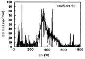
도 16 내지 도 20에 도시된 각 샘플의 배기가스 정화용 촉매 특성은 시차 열중량 동시 분석 장치에 의해 상술한 바와 동일한 조건 하에 평가된다. 그 결과가 도 22 내지 도 26에 도시된다.The catalytic characteristics for exhaust gas purification of each sample shown in FIGS. 16 to 20 are evaluated under the same conditions as described above by a differential thermogravimetric analysis device. The results are shown in FIGS. 22-26.
도 22, 도 23, 도 24, 도 25 및 도 26은 각각 125℃ × 48 시간, 140℃ × 48 시간, 150℃ × 48 시간, 175℃ × 48 시간 및 190℃ × 6 시간의 수열처리 온도로 합성된 델라포사이트-타입 AgAlO2의 가열 온도와 중량의 변화 사이의 관계를 도시한 도면이다.Figures 22, 23, 24, 25 and 26 show the hydrothermal treatment temperatures of 125 ° C. × 48 hours, 140 ° C. × 48 hours, 150 ° C. × 48 hours, 175 ° C. × 48 hours and 190 ° C. × 6 hours, respectively. The relationship between the heating temperature and the weight change of the synthesized delafossite-type AgAlO 2 is shown.
도 22 내지 도 26에 도시된 바와 같이, 수열처리 온도로 합성된 모든 샘플은 약 300 내지 400℃의 저온에서부터 600℃까지의 넓은 범위에서 탄소 미세 입자를 연소시킬 수 있다.As shown in Figures 22 to 26, all samples synthesized at the hydrothermal temperature can burn carbon fine particles in a wide range from a low temperature of about 300 to 400 ℃ to 600 ℃.
(예 6)(Example 6)
예 6에서, 상술한 수열 합성으로 제조된 델라포사이트-타입 AgAlO2는 4시간 동안 1000℃의 온도로 가열되어 분해된다.In Example 6, the delafossite-type AgAlO 2 prepared by the hydrothermal synthesis described above is heated to a temperature of 1000 ° C. for 4 hours to decompose.
도 27은 XRD 분석에 의해 델라포사이트-타입 AgAlO2의 열분해 물질의 X선 회절 스펙트럼을 도시한 도면이다. 측정 조건은 상술한 바와 동일하다. 도 27에 도시된 바와 같이, X선은 단지 은만을 확인할 수 있으나, 열분해 물질의 조성은 Al에 대한 Ag의 비 1:1을 갖는다(Ag:Al=1:1).FIG. 27 is a diagram showing an X-ray diffraction spectrum of a pyrolysis material of delafossite-type AgAlO 2 by XRD analysis. Measurement conditions are the same as above. As shown in FIG. 27, X-rays can only identify silver, but the composition of the pyrolysis material has a ratio of Ag to Al of 1: 1 (Ag: Al = 1: 1).
도 28은 열분해 물질의 라만 스펙트럼을 도시한 도면이다. 측정 조건은 상술한 바와 동일하다. 스펙트럼은 도 28에 도시된 바와 같이 200 내지 400㎝-1, 600 내지 800㎝-1, 1000 내지 1200㎝-1의 세 개의 피크를 갖는다. 열분해 물질은 전자 현미경으로 관측된다. 도 29는 전자 현미경으로 관측된 열분해 물질의 현미경 사진을 도시한다. 열분해 물질은 층상 구조를 갖는 것으로 확인된다.28 shows a Raman spectrum of a pyrolysis material. Measurement conditions are the same as above. Spectrum has three peaks of 200 to the road, as shown in 400㎝ 28-1600 to 800
열분해 물질의 배기가스 정화용 촉매 특성은 시차 열중량 동시 분석 장치에 의해 상술한 바와 동일한 조건 하에 평가된다. 그 결과가 도 30에 도시된다. 도 30은 본 예의 열분해 물질의 가열 온도와 중량 변화 사이의 관계를 도시한 도면이다. 상술한 설명에서 알 수 있듯이, 물질은 약 300 내지 400℃의 저온에서도 탄소 미세 입자를 연소시킬 수 있다.Catalyst characteristics for exhaust gas purification of the pyrolysis material are evaluated by the differential thermogravimetric analysis device under the same conditions as described above. The result is shown in FIG. 30 is a diagram showing the relationship between the heating temperature and the weight change of the pyrolysis material of the present example. As can be seen from the above description, the material can burn carbon fine particles even at low temperatures of about 300 to 400 ° C.
(예 7)(Example 7)
예 7에서, 복합 질산염이 열분해된다. 구체적으로, 질산은 및 질산 알루미늄은 동일 몰량으로 물에 용해되어, 물질(AgAl(NO3)4)을 형성하고, 이후 850℃의 온도까지 가열되어 열분해된다.In Example 7, the complex nitrate is pyrolyzed. Specifically, silver nitrate and aluminum nitrate are dissolved in water in the same molar amount to form a substance (AgAl (NO 3 ) 4 ), which is then heated to a temperature of 850 ° C. to be pyrolyzed.
도 31은 XRD에 의한 복합 질산염의 열분해 물질의 X선 회절 스펙트럼을 도시한 도면이다. 측정 조건은 상술한 바와 동일하다. 도 31에 도시된 바와 같이, 은 및 α 알루미나의 적은 양만이 X선 스펙트럼에 의해 확인될 수 있으나, 열분해 물질의 조성은 Al에 대한 Ag의 비 1:1을 갖는다.Fig. 31 shows the X-ray diffraction spectrum of the pyrolyzed substance of the complex nitrate by XRD. Measurement conditions are the same as above. As shown in FIG. 31, only a small amount of silver and α alumina can be identified by the X-ray spectrum, but the composition of the pyrolytic material has a ratio of Ag to Al 1: 1.
도 32는 복합 질산염의 열분해 물질의 라만 스펙트럼을 도시한다. 또한, 도 32는 α알루미나에 AgNO3를 담지하기 위해, 1:1의 Ag에 대한 Al의 비 1:1을 갖도록 α알루미나를 AgNO3로 침지시키고, 850℃의 온도로 알루미나를 열분해하여 형성된 비교예의 물질의 라만 스펙트럼을 도시한다. 측정 조건은 상술한 바와 동일하다.FIG. 32 shows Raman spectra of pyrolysis materials of complex nitrates. FIG. In addition, FIG. 32 is a comparison formed by immersing alumina with AgNO 3 to have a ratio of Al to 1: 1 of Ag in order to carry AgNO 3 on α alumina, and pyrolyzing alumina at a temperature of 850 ° C. The Raman spectrum of the example material is shown. Measurement conditions are the same as above.
도 32에 도시된 바와 같이, 본 예의 복합 질산염의 열분해 물질도 200 내지 400㎝-1, 600 내지 800㎝-1, 1000 내지 1200㎝-1의 세 개의 피크를 갖는다. 열분해 물질은 전자 현미경으로 관측된다. 도 33은 전자 현미경으로 관측된 열분해 물질의 현미경 사진을 도시한다. 열분해 물질도 층상 구조를 갖는 것이 확인된다.As shown in Fig. 32, the pyrolysis material of the composite nitrate of the present example also has three peaks of 200 to 400 cm -1 , 600 to 800 cm -1 and 1000 to 1200 cm -1 . Pyrolysates are observed under an electron microscope. 33 shows a micrograph of the pyrolysis material observed with an electron microscope. It is confirmed that the pyrolysis substance also has a layered structure.
열분해 물질의 배기가스의 정화용 촉매 특성은 시차 열중량 동시 분석 장치에 의해 상술한 바와 동일한 조건 하에 평가된다. 그 결과가 도 34에 도시된다. 도 34는 본 예에서 복합 질산염의 열분해 물질의 가열 온도와 중량 변화 사이의 관계를 도시한 도면이다. 상술한 설명에서 알 수 있듯이, 상기 물질은 약 300 내지 400℃의 저온에서도 탄소 미세 입자를 연소시킬 수 있다.The catalytic characteristics for purifying exhaust gas of the pyrolysis material are evaluated by the differential thermogravimetric analysis device under the same conditions as described above. The result is shown in FIG. FIG. 34 is a diagram showing the relationship between the heating temperature and the weight change of the pyrolysis material of the composite nitrate in this example. As can be seen from the above description, the material can burn carbon fine particles even at low temperatures of about 300 to 400 ° C.
(예 8)(Example 8)
예 8에서, 델라포사이트 타입 AgAlO2는 제3 수열 합성에 의해 촉매 재료로 제조된다.In Example 8, the delafossite type AgAlO 2 is made of a catalytic material by third hydrothermal synthesis.
우선, 4g의 NaOH, 5.0g의 천이 알루미나 및 11.6g의 Ag2O이 100ml의 이온교환수에 분산된다. 분산액은 테프론(등록 상표)사에서 제조한 용기를 구비한 압력 용기로 봉입된다. 이후 분산액은 48시간 동안 175℃의 온도로 수열처리된다. 처리된 액은 물로 세척되고 3회 여과된다. 여과 이후 잔류 물질은 검은 회색을 갖는다. X선 회절(XRD)의 결과, 이 물질은 델라포사이트-타입 AgAlO2 및 산화은으로 확인된다.First, 4 g of NaOH, 5.0 g of transition alumina and 11.6 g of Ag 2 O are dispersed in 100 ml of ion-exchanged water. The dispersion is enclosed in a pressure vessel with a vessel made by Teflon®. The dispersion is then hydrothermally treated at a temperature of 175 ° C. for 48 hours. The treated liquid is washed with water and filtered three times. The residue after filtration has a black grey. As a result of X-ray diffraction (XRD), this material is identified as delafossite-type AgAlO 2 and silver oxide.
이후, 산화은을 함유한 델라포사이트-타입 AgAlO2이 10% 암모니아수에 분산되고, 이어서 물로 충분히 세척되고 건조된다. 따라서, 본 예에서도, 예 1에서와 동일한 델라포사이트-타입 AgAlO2이 획득된다.Thereafter, the delafossite-type AgAlO 2 containing silver oxide is dispersed in 10% ammonia water and then sufficiently washed with water and dried. Therefore, also in this example, the same delafossite-type AgAlO 2 as in Example 1 is obtained.
(예 9)(Example 9)
예 9에서, 델라포사이트-타입 AgAlO2는 제4 수열 합성에 의해 촉매 재료로 제조된다.In Example 9, delafossite-type AgAlO 2 is prepared from the catalytic material by fourth hydrothermal synthesis.
우선, 4g(그램)의 NaOH, 7.8g의 천이 알루미나 및 11.6g의 Ag2O이 100ml의 이온 교환수에 분산된다. 분산액은 테프론(등록 상표)사에서 제조한 용기를 구비한 압력 용기로 봉입된다. 이후 분산액은 48시간 동안 175℃의 온도로 수열처리된다. 처리된 액은 물로 세척되고 3회 여과된다. 여과 이후 잔류 물질은 검은 회색을 갖는다. X선 회절(XRD)의 결과, 이 물질은 델라포사이트-타입 AgAlO2 및 산화은으로 확인된다.First, 4 g (grams) of NaOH, 7.8 g of transition alumina and 11.6 g of Ag 2 O are dispersed in 100 ml of ion exchanged water. The dispersion is enclosed in a pressure vessel with a vessel made by Teflon®. The dispersion is then hydrothermally treated at a temperature of 175 ° C. for 48 hours. The treated liquid is washed with water and filtered three times. The residue after filtration has a black grey. As a result of X-ray diffraction (XRD), this material is identified as delafossite-type AgAlO 2 and silver oxide.
이후, 산화은을 함유한 델라포사이트-타입 AgAlO2이 10% 암모니아수에 분산되고, 이어서 물로 세척되고 충분히 건조된다. 따라서, 본 예에서도, 예 1에서와 동일한 델라포사이트-타입 AgAlO2이 획득된다.Thereafter, delafossite-type AgAlO 2 containing silver oxide is dispersed in 10% ammonia water, followed by washing with water and drying sufficiently. Therefore, also in this example, the same delafossite-type AgAlO 2 as in Example 1 is obtained.
(예 10)(Example 10)
예 10에서, Ag-β 알루미나 및 Ag의 적층 구조로 구성된 촉매 재료가 제5 수열 합성법으로 제조된다.In Example 10, a catalytic material consisting of a laminated structure of Ag-β alumina and Ag is prepared by a fifth hydrothermal synthesis method.
우선, 천이 알루미나로서 기능하는 5g의 θ 알루미나 및 11g의 산화은이 100ml의 이온 교환수에 분산된다. 이후, 6g의 아세트산이 분산액에 추가되어 교반 되고, 압력 용기로 봉입된 이후, 48시간 동안 175℃의 온도로 수열처리된다.First, 5 g of θ alumina and 11 g of silver oxide serving as transition alumina are dispersed in 100 ml of ion-exchanged water. Thereafter, 6 g of acetic acid was added to the dispersion and stirred, and after being sealed into a pressure vessel, hydrothermally treated at a temperature of 175 ° C. for 48 hours.
획득된 슬러리는 원심 분리기에 의해 고체 및 액체로 분리되고, 고체의 X선 회절 측정이 동일 조건 하에 실행된다. 결과는 도 35에서 파선으로 표시된 (소성 전의 )X선 회절 스펙트럼으로 표현된다. 따라서, 고체는 은 및 베이마이트의 혼합물로 확인된다.The obtained slurry is separated into a solid and a liquid by a centrifugal separator, and the X-ray diffraction measurement of the solid is performed under the same conditions. The results are expressed as X-ray diffraction spectra (before firing), indicated by broken lines in FIG. 35. Thus, the solid is identified as a mixture of silver and boehmite.
고체는 대기 분위기에서 600℃의 온도로 소성된다. 도 35에서 실선으로 표시된 X선 회절 스펙트럼은 소성 이후 소성물의 스펙트럼이다. 상기 표시된 스펙트럼으로부터, 은이 확인되지만, 알루미나의 형태는 명확하지 않다.The solid is calcined at a temperature of 600 ° C. in the atmospheric atmosphere. The X-ray diffraction spectrum represented by the solid line in FIG. 35 is the spectrum of the fired product after firing. From the spectra indicated above, silver is identified, but the form of alumina is not clear.
따라서, 단면 TEM 관측 및 전자 회절이 실행된다. 도 36은 단면 TEM 관측의 결과로서 본 예의 소성물의 개략적인 단면도이다.Thus, cross-sectional TEM observation and electron diffraction are performed. 36 is a schematic cross-sectional view of the fired matter of this example as a result of cross-sectional TEM observation.
도 36에 도시된 바와 같이, 은 층(700) 및 알루미나 층(701)이 10nm 이하의 적층 주기를 갖도록 교호식으로 적층된다. 은은 금속 은 또는 은 이온으로 존재한다. 은의 하나의 층은 도 36에 도시된 바와 같이 얇은 부분 및 두꺼운 부분을 갖는다.As shown in FIG. 36, the
알루미나는 알루미나 층(701)에서 Ag를 함유한 전자 회절로 확인된다. 즉, 본 예에서, 알루미나는 내부에 Ag를 함유한 Ag-β 알루미나이다. 본 예의 촉매 재료는 Ag-β 알루미나 및 Ag로 구성된 적층 구조의 촉매 재료로 확인된다.Alumina is identified by electron diffraction containing Ag in the
예 4에 표시되는 델라포사이트-타입 AgAlO2, 예 6에 표시되는 델라포사이트-타입 AgAlO2의 열분해 물질 및 예 7에 표시되는 복합 질산염의 열분해 물질에 대해 동일한 단면 TEM 관측이 실행된다. 그 결과, 각 물질은 도 36에 도시된 바와 같이, 알루미늄 및 은의 적층 구조를 갖는 촉매 재료로 확인된다. 각 예의 적층 주기는 예를 들어, 예 4, 예 6 및 예 7에서 각각 0.6nm, 5nm 및 10nm를 포함한다.Example 4 Four della sites in-type AgAlO 2, Example 6 della Four sites in-type AgAlO the same cross-section TEM observation for the thermal decomposition material of the composite nitrate shown in Example 7 of the second material and the pyrolysis is carried out. As a result, each material was identified as a catalyst material having a laminated structure of aluminum and silver, as shown in FIG. The lamination period of each example includes, for example, 0.6 nm, 5 nm, and 10 nm in Examples 4, 6, and 7, respectively.
또한, 본 예에서, 라만 스펙트럼은 예 4에서와 동일한 방식으로 측정된다. 각 예의 촉매 재료와 같이, 본 예의 촉매 재료는 600 내지 800cm-1의 피크를 갖고 O-Ag-O 구조를 갖는 것으로 확인된다.Also in this example, the Raman spectrum is measured in the same manner as in Example 4. Like the catalyst material of each example, the catalyst material of this example is confirmed to have a peak of 600 to 800 cm −1 and to have an O—Ag—O structure.
본 예의 촉매 재료의 배기가스 정화용 촉매 특성은 시차 열중량 분석 장치에 의해 상술한 바와 동일한 조건 하에 평가된다. 그 결과가 도 37에 도시된다. 도 37은 본 예의 촉매 재료의 가열 온도와 중량 변화 사이의 관계를 도시한 도면이다. 도면에서 알 수 있듯이, 본 예에서도, 촉매 재료는 약 300 내지 400℃의 저온에서 탄소 미립자를 연소시킬 수 있다.The catalyst characteristics for exhaust gas purification of the catalyst material of this example are evaluated by the differential thermogravimetric analyzer under the same conditions as described above. The result is shown in FIG. 37 is a diagram showing the relationship between the heating temperature and the weight change of the catalyst material of the present example. As can be seen from the figure, even in this example, the catalyst material can burn carbon fine particles at a low temperature of about 300 to 400 ° C.
(예 11)(Example 11)
예 11에서, Ag-β 알루미나 및 Ag의 적층 구조로 구성된 촉매 재료는 제6 수열 합성법에 의해 촉매 재료로 제조된다. 예 11에서, 촉매 재료는 8g의 NaAlO2이 θ 알루미나 대신 사용된 점을 제외하면 예 10에서와 동일한 방식으로 제조된다.In Example 11, the catalyst material composed of the laminated structure of Ag-β alumina and Ag is made of the catalyst material by the sixth hydrothermal synthesis method. In Example 11, the catalytic material was prepared in the same manner as in Example 10 except that 8 g of NaAlO 2 was used instead of θ alumina.
또한, 본 예에서, 예 10과 같이, Ag-β 알루미나 및 Ag의 적층 구조의 사용으로 촉매 재료를 얻을 수 있다. 본 예의 촉매 재료의 배기가스 정화용 촉매 특성이 평가된다. 따라서, 촉매 재료는 약 300 내지 400℃의 저온에서 탄소 미세 입자를 연소시킬 수 있다.In addition, in this example, as in Example 10, the catalyst material can be obtained by using a laminated structure of Ag-β alumina and Ag. The catalyst characteristics for exhaust gas purification of the catalyst material of this example are evaluated. Thus, the catalytic material can burn carbon fine particles at low temperatures of about 300 to 400 ° C.
(예 12)(Example 12)
예 12에서, Ag-β 알루미나 및 Ag의 적층 구조로 형성된 촉매 재료는 제7 수열 합성법에 의해 촉매 재료로 제조된다. 예 12에서, 촉매 재료는 아세트산을 사용하지 않는 점 즉, 아세트산 대신 아세트산 나트륨 8g이 사용된다는 점을 제외하면 예 10에서와 동일한 방식으로 제조된다.In Example 12, the catalyst material formed of the laminated structure of Ag-β alumina and Ag is made of the catalyst material by the seventh hydrothermal synthesis method. In Example 12, the catalyst material is prepared in the same manner as in Example 10 except that acetic acid is not used, i.e. 8 g of sodium acetate is used instead of acetic acid.
본 예에서도, 예 10과 같이, Ag-β 알루미나 및 Ag의 적층 구조의 사용으로 촉매 재료를 얻을 수 있다. 본 예의 촉매 재료의 배기가스 정화용 촉매 특성이 평가된다. 따라서, 촉매 재료는 약 300 내지 400℃의 저온에서 탄소 미세 입자를 연소시킬 수 있다.Also in this example, as in Example 10, a catalyst material can be obtained by using a laminated structure of Ag-β alumina and Ag. The catalyst characteristics for exhaust gas purification of the catalyst material of this example are evaluated. Thus, the catalytic material can burn carbon fine particles at low temperatures of about 300 to 400 ° C.
(예 13)(Example 13)
층상 은 알루미나 적층체에서 알루미나에 대한 은의 원소 비는 0.25 이상이 바람직하다. 예 13에서, 원소 비를 한정한 이유를 이하에서 설명한다. 그 이유는 본 발명자들에 의해 실행된 이하의 실험 결과를 기초로 한다.The element ratio of silver to alumina in the layered silver alumina laminate is preferably 0.25 or more. In Example 13, the reason for limiting the element ratio is described below. The reason is based on the following experimental results carried out by the present inventors.
우선, 1.5g의 θ 알루미나, 0.35g(x=0.1), 0.70g(x=0.2), 0.88g(x=0.25), 1.75g(x=0.5), 2.63g(x=0.75)의 산화은, 0.18g(x=0.1), 0.36g(x=0.2), 0.45g(x=0.25), 0.9g(x=0.5), 1.3g(x=0.25)의 아세트산이 100ml의 이온 교환 수에 각각 추가되고, 이후 압력 용기 내에서 40 시간 동안 175℃의 온도로 가열됨으로써 졸 용액을 얻는다. 이렇게 획득된 졸 용액은 건조되고, 5시간 동안 600℃의 온도로 소성되어, 각각의 시료를 형성한다. 즉, 본 예에서, 각각의 시료는 상기 제5 수열 합성법으로 제조된다.First, 1.5 g of θ alumina, 0.35 g (x = 0.1), 0.70 g (x = 0.2), 0.88 g (x = 0.25), 1.75 g (x = 0.5), and 2.63 g (x = 0.75) of silver oxide, 0.18 g (x = 0.1), 0.36 g (x = 0.2), 0.45 g (x = 0.25), 0.9 g (x = 0.5), and 1.3 g (x = 0.25) of acetic acid were added to 100 ml of ion-exchanged water, respectively. The sol solution is then obtained by heating to a temperature of 175 ° C. for 40 hours in a pressure vessel. The sol solution thus obtained is dried and calcined at a temperature of 600 ° C. for 5 hours to form each sample. That is, in this example, each sample is produced by the fifth hydrothermal synthesis method.
산화은 및 아세트산 각각의 중량에 대한 괄호 내의 x값은 Al 원자에 대한 아세트산 및 Ag 원자 각각의 원소비를 나타낸다. 획득된 각각의 시료의 조성은 알루미늄에 대한 은의 원소비 x를 사용하여 xAg/[0.5(Al2O3)]로 표현된다.The w value in parentheses for the weights of silver oxide and acetic acid respectively indicates the element ratio of acetic acid and Ag atoms to Al atoms respectively. The composition of each sample obtained is expressed as xAg / [0.5 (Al 2 O 3 )] using the elemental ratio x of silver to aluminum.
즉, 본 예에서, θ알루미나 양에 대해 아세트산 및 산화은의 전체량이 변경되어, 알루미늄에 대한 은의 원소비 x가 각각 0.1, 0.2, 0.25, 0.5 및 0.75인 시료를 제조한다. 다양한 원소비 x를 갖는 각각의 시료는 5중량%의 매연에 혼합되어, 상술한 바와 동일한 방식으로 열중량 분석된다. 열중량 분석의 결과가 도 38에 도시된다.That is, in this example, the total amounts of acetic acid and silver oxide are changed with respect to the amount of? Each sample having various element ratios x is mixed in 5% by weight soot and thermogravimetrically analyzed in the same manner as described above. The results of thermogravimetric analysis are shown in FIG. 38.
도 38에서, 횡축은 온도(단위 ℃)를 나타내고, 종축은 중량 감소율(임의 단위)을 나타낸다. 도 38은 알루미늄에 대한 은의 다양한 원소비를 갖는 시료의 중량 감소율과 온도 사이의 관계를 도시한다. 도 38에 도시된 결과로부터 알 수 있듯이, 알루미늄에 대한 은의 원소비 x가 0.25 이상일 때, 중량 감소율이 클수록 300 내지 400℃의 온도에서 관측될 수 있어, 우수한 연소가 저온에서 실현될 수 있다.In FIG. 38, the horizontal axis represents temperature (unit ° C.), and the vertical axis represents weight loss rate (arbitrary unit). 38 shows the relationship between the weight loss rate and the temperature of a sample having various element ratios of silver to aluminum. As can be seen from the results shown in FIG. 38, when the element ratio x of silver to aluminum is 0.25 or more, the larger the weight reduction rate can be observed at a temperature of 300 to 400 ° C., so that excellent combustion can be realized at low temperature.
(다른 실시예)(Another embodiment)
예 2에 도시된 벌집형 구조체에서, 예 3 내지 예 12의 촉매 재료는 격벽(22)에 담지된다. 촉매 재료의 담지 방법은 상술한 예 2의 방법과 동일하다. 촉매 재료를 격벽(22)에 담지할 때, 촉매 재료는 격벽(22)의 전체에 담지될 수 있거나 또는 격벽의 일부에 담지될 수 있다. 이와 달리, 촉매 재료를 함유한 슬러리가 흡인 등에 의해 벌집형 구조체에 담지되도록 사용될 수 있다.In the honeycomb structure shown in Example 2, the catalytic material of Examples 3 to 12 is supported on the
세라믹 벌집형 구조체는 도 3 내지 도 5에 도시된 것으로 제한되지 않는다. 내연 기관으로부터 배출되는 매연을 연소시키는 촉매 재료를 담지할 수 있도록 채용되는 임의의 다른 세라믹 벌집형 구조체가 사용될 수 있다.The ceramic honeycomb structure is not limited to that shown in FIGS. Any other ceramic honeycomb structure can be used that is adapted to support the catalytic material that burns the soot emitted from the internal combustion engine.
Claims (12)
Applications Claiming Priority (6)
| Application Number | Priority Date | Filing Date | Title |
|---|---|---|---|
| JP2007072627 | 2007-03-20 | ||
| JPJP-P-2007-072627 | 2007-03-20 | ||
| JPJP-P-2007-284949 | 2007-11-01 | ||
| JP2007284949 | 2007-11-01 | ||
| JP2008038489 | 2008-02-20 | ||
| JPJP-P-2008-038489 | 2008-02-20 |
Publications (2)
| Publication Number | Publication Date |
|---|---|
| KR20090115872A KR20090115872A (en) | 2009-11-09 |
| KR101078552B1 true KR101078552B1 (en) | 2011-11-01 |
Family
ID=39808164
Family Applications (1)
| Application Number | Title | Priority Date | Filing Date |
|---|---|---|---|
| KR1020097019476A Expired - Fee Related KR101078552B1 (en) | 2007-03-20 | 2008-03-19 | Catalyst material |
Country Status (6)
| Country | Link |
|---|---|
| US (1) | US8501662B2 (en) |
| EP (1) | EP2127730B1 (en) |
| JP (1) | JP4992773B2 (en) |
| KR (1) | KR101078552B1 (en) |
| CN (1) | CN101636221B (en) |
| WO (1) | WO2008120582A1 (en) |
Families Citing this family (8)
| Publication number | Priority date | Publication date | Assignee | Title |
|---|---|---|---|---|
| JP2009219972A (en) * | 2007-03-20 | 2009-10-01 | Denso Corp | Method for producing catalyst material |
| JP2009219971A (en) * | 2007-03-20 | 2009-10-01 | Denso Corp | Ceramic honeycomb structure |
| JP5051093B2 (en) * | 2008-10-14 | 2012-10-17 | 株式会社デンソー | Method for producing catalyst carrier |
| JP5434474B2 (en) * | 2009-10-26 | 2014-03-05 | 株式会社デンソー | Method for producing catalyst structure |
| JP5545167B2 (en) * | 2010-10-21 | 2014-07-09 | 株式会社デンソー | Catalyst material and method for producing the same |
| EP2726177B1 (en) * | 2011-07-01 | 2016-01-06 | Toyota Jidosha Kabushiki Kaisha | Exhaust purification system for internal combustion engine |
| CN103566920B (en) | 2012-08-01 | 2016-05-25 | 通用电气公司 | Material and the exhaust apparatus and the method that use it |
| JP6281439B2 (en) * | 2014-08-04 | 2018-02-21 | 株式会社デンソー | Exhaust gas purification filter and manufacturing method thereof |
Citations (1)
| Publication number | Priority date | Publication date | Assignee | Title |
|---|---|---|---|---|
| JP2000027637A (en) * | 1998-07-10 | 2000-01-25 | Mitsubishi Motors Corp | NOx reduction system for combustion exhaust gas |
Family Cites Families (50)
| Publication number | Priority date | Publication date | Assignee | Title |
|---|---|---|---|---|
| US3974255A (en) * | 1973-03-12 | 1976-08-10 | Atlantic Richfield Company | Method for treatment of engine exhaust gases |
| JPS5067294A (en) | 1973-10-19 | 1975-06-05 | ||
| JPS5095188A (en) | 1973-12-27 | 1975-07-29 | ||
| JPS58128128A (en) * | 1982-01-27 | 1983-07-30 | Toyota Motor Corp | Filter for purifying exhaust gas of internal-combustion engine |
| JPS6186944A (en) * | 1984-10-02 | 1986-05-02 | Matsushita Electric Ind Co Ltd | Catalyst for exhaust gas purification |
| JPS6220613A (en) * | 1985-07-19 | 1987-01-29 | Cataler Kogyo Kk | Catalyst filter for removal of particulate |
| JPS6320028A (en) | 1986-07-12 | 1988-01-27 | Nissan Motor Co Ltd | Catalyst for cleaning exhaust gas |
| JPH02261511A (en) * | 1989-03-31 | 1990-10-24 | Komatsu Ltd | Catalyst for removing particulates from diesel exhaust and its filter |
| JP2968615B2 (en) | 1991-06-25 | 1999-10-25 | 株式会社神戸製鋼所 | Automatic bolt tightening method |
| JP2506598B2 (en) | 1992-03-12 | 1996-06-12 | 工業技術院長 | Nitrogen oxide removal method |
| JPH08173806A (en) | 1994-12-26 | 1996-07-09 | Nissan Motor Co Ltd | Exhaust gas purification catalyst and method for producing the same |
| US5834395A (en) * | 1995-03-24 | 1998-11-10 | Next Generation Catalyst Research Institute, Co., Ltd. | Catalyst for controlling emissions |
| JP3453239B2 (en) * | 1995-08-18 | 2003-10-06 | 財団法人石油産業活性化センター | Catalyst for catalytic reduction of nitrogen oxides |
| EP0788829B1 (en) * | 1996-02-08 | 2004-09-22 | Sakai Chemical Industry Co., Ltd., | Catalyst and method for catalytic reduction of nitrogen oxides |
| JP3777696B2 (en) | 1997-02-07 | 2006-05-24 | トヨタ自動車株式会社 | Metal fine particle supported oxide catalyst |
| JPH11123330A (en) | 1997-08-20 | 1999-05-11 | Hino Motors Ltd | Exhaust gas cleaning catalyst and manufacture thereof |
| JPH11169717A (en) | 1997-12-09 | 1999-06-29 | Tokyo Gas Co Ltd | Lean-burn engine catalysts |
| JPH11200849A (en) | 1998-01-08 | 1999-07-27 | Mitsubishi Motors Corp | Engine exhaust gas purification device |
| JP2000015097A (en) | 1998-06-30 | 2000-01-18 | Toyota Motor Corp | Catalyst production method |
| JP2000025548A (en) | 1998-07-16 | 2000-01-25 | Tokai Rika Co Ltd | Air bag device |
| JP2000350933A (en) | 1999-06-11 | 2000-12-19 | Suzuki Motor Corp | Exhaust gas purification catalyst and method for producing the same |
| US6314722B1 (en) * | 1999-10-06 | 2001-11-13 | Matros Technologies, Inc. | Method and apparatus for emission control |
| JP3736242B2 (en) | 1999-12-02 | 2006-01-18 | 松下電器産業株式会社 | Exhaust gas purification material and method for producing the same |
| JP4540785B2 (en) * | 2000-01-11 | 2010-09-08 | 日揮触媒化成株式会社 | Exhaust gas purification catalyst molding |
| US6606856B1 (en) * | 2000-03-03 | 2003-08-19 | The Lubrizol Corporation | Process for reducing pollutants from the exhaust of a diesel engine |
| JP3494114B2 (en) | 2000-03-28 | 2004-02-03 | トヨタ自動車株式会社 | Exhaust gas purification method and exhaust gas purification device |
| ATE296160T1 (en) * | 2000-04-11 | 2005-06-15 | Accentus Plc | PLASMA-ASSISTED GAS TREATMENT |
| GB0020287D0 (en) * | 2000-08-17 | 2000-10-04 | Aea Technology Plc | The catalytic treatment of gases |
| JP2002255548A (en) | 2001-02-26 | 2002-09-11 | Japan Science & Technology Corp | Mixed layer laminated irregular crystal structure delafossite oxide and method for producing the same |
| JP2002370032A (en) | 2001-06-13 | 2002-12-24 | Sumitomo Metal Mining Co Ltd | Exhaust gas purifying catalyst, and molded catalyst, catalyst coated structure and exhaust gas purifying method using the same |
| JP2002370030A (en) * | 2001-06-13 | 2002-12-24 | Sumitomo Metal Mining Co Ltd | Exhaust gas purification catalyst and exhaust gas purification method using the same |
| JP2004066106A (en) | 2002-08-06 | 2004-03-04 | Hino Motors Ltd | Exhaust gas purification device |
| JP2005009454A (en) | 2003-06-20 | 2005-01-13 | Tokyo Yogyo Co Ltd | Exhaust gas purification filter |
| JP2005007360A (en) * | 2003-06-20 | 2005-01-13 | Tokyo Yogyo Co Ltd | Exhaust gas purification filter |
| JP2005097642A (en) * | 2003-09-22 | 2005-04-14 | Tanaka Kikinzoku Kogyo Kk | Precious metal-metal oxide composite cluster |
| US7541010B2 (en) * | 2003-12-19 | 2009-06-02 | Caterpillar Inc. | Silver doped catalysts for treatment of exhaust |
| US20050135977A1 (en) * | 2003-12-19 | 2005-06-23 | Caterpillar Inc. | Multi-part catalyst system for exhaust treatment elements |
| US7146802B2 (en) * | 2004-10-07 | 2006-12-12 | General Motors Corporation | Reducing NOx emissions with a staged catalyst |
| JP4525909B2 (en) | 2004-10-28 | 2010-08-18 | 戸田工業株式会社 | Water gas shift reaction catalyst, method for producing the same, and method for producing water gas |
| JP2006239544A (en) | 2005-03-02 | 2006-09-14 | Denso Corp | Catalyst body and method for producing the same |
| JP4265561B2 (en) | 2005-04-04 | 2009-05-20 | 株式会社デンソー | Automobile exhaust gas purification catalyst body |
| JP4739870B2 (en) | 2005-09-05 | 2011-08-03 | アイシン精機株式会社 | Sunglasses detection device and face center position detection device |
| JP2007196135A (en) * | 2006-01-26 | 2007-08-09 | Honda Motor Co Ltd | Exhaust gas purification catalyst and method for producing the same |
| JP5085176B2 (en) | 2006-04-07 | 2012-11-28 | 本田技研工業株式会社 | Exhaust gas purification catalyst and exhaust gas purification device |
| JP4989096B2 (en) | 2006-04-14 | 2012-08-01 | ケイミュー株式会社 | Roof building and roof building structure |
| JP2008038489A (en) | 2006-08-07 | 2008-02-21 | Calsonic Kansei Corp | Door opening and closing assisting device |
| JP4828358B2 (en) | 2006-09-04 | 2011-11-30 | カヤバ工業株式会社 | Operation management device |
| JP5095188B2 (en) | 2006-11-28 | 2012-12-12 | 株式会社ブラザーエンタープライズ | Ball launcher |
| JP2008229608A (en) | 2007-11-01 | 2008-10-02 | Denso Corp | Catalyst material and ceramic honeycomb structure |
| JP5067294B2 (en) | 2008-07-17 | 2012-11-07 | パナソニック株式会社 | Radio wave receiver |
-
2008
- 2008-03-14 JP JP2008065361A patent/JP4992773B2/en not_active Expired - Fee Related
- 2008-03-19 KR KR1020097019476A patent/KR101078552B1/en not_active Expired - Fee Related
- 2008-03-19 WO PCT/JP2008/055103 patent/WO2008120582A1/en not_active Ceased
- 2008-03-19 EP EP08722478.8A patent/EP2127730B1/en not_active Not-in-force
- 2008-03-19 US US12/530,910 patent/US8501662B2/en not_active Expired - Fee Related
- 2008-03-19 CN CN2008800089234A patent/CN101636221B/en not_active Expired - Fee Related
Patent Citations (1)
| Publication number | Priority date | Publication date | Assignee | Title |
|---|---|---|---|---|
| JP2000027637A (en) * | 1998-07-10 | 2000-01-25 | Mitsubishi Motors Corp | NOx reduction system for combustion exhaust gas |
Also Published As
| Publication number | Publication date |
|---|---|
| KR20090115872A (en) | 2009-11-09 |
| EP2127730A4 (en) | 2011-04-06 |
| US8501662B2 (en) | 2013-08-06 |
| EP2127730B1 (en) | 2015-07-08 |
| JP4992773B2 (en) | 2012-08-08 |
| CN101636221B (en) | 2013-07-10 |
| WO2008120582A1 (en) | 2008-10-09 |
| EP2127730A1 (en) | 2009-12-02 |
| JP2009219970A (en) | 2009-10-01 |
| US20100093529A1 (en) | 2010-04-15 |
| CN101636221A (en) | 2010-01-27 |
Similar Documents
| Publication | Publication Date | Title |
|---|---|---|
| KR20090115871A (en) | Method of producing catalyst material | |
| KR101078552B1 (en) | Catalyst material | |
| KR20090113380A (en) | Ceramic honeycomb structure | |
| JP4907860B2 (en) | Filter catalyst | |
| KR102018484B1 (en) | Platinum group metal (pgm) catalyst for treating exhaust gas | |
| ES2391991T3 (en) | Catalysts to reduce NOx in an exhaust gas stream and preparation methods | |
| JP3936238B2 (en) | Catalyst body and method for producing catalyst body | |
| JP2001327818A (en) | Ceramic filter and filtration device | |
| WO2008035652A1 (en) | Catalyst for burning carbon-containing substance, process for production of the catalyst, material having catalyst carried thereon, and process for production of the material | |
| US11731111B2 (en) | Porous ceramic structure and method of producing porous ceramic structure | |
| JP5805603B2 (en) | Exhaust gas purification catalyst | |
| KR20140061353A (en) | Device for the purification of exhaust gases from a heat engine, comprising a ceramic carrier and an active phase chemically and mechanically anchored in the carrier | |
| KR20140082632A (en) | Device for the purification of exhaust gases from a heat engine, comprising a ceramic carrier and an active phase mechanically anchored in the carrier | |
| CN113441149A (en) | Porous ceramic structure and method for producing porous ceramic structure | |
| JP5051093B2 (en) | Method for producing catalyst carrier | |
| JP2011074882A (en) | Exhaust emission control device | |
| JP2008229608A (en) | Catalyst material and ceramic honeycomb structure | |
| Zhang et al. | In situ growth of ZnO nanorods on monolithic diesel particulate filters and supporting potassium for catalytic soot combustion | |
| WO2014083869A1 (en) | Catalyst for discharge gas purification |
Legal Events
| Date | Code | Title | Description |
|---|---|---|---|
| A201 | Request for examination | ||
| P11-X000 | Amendment of application requested |
St.27 status event code: A-2-2-P10-P11-nap-X000 |
|
| P13-X000 | Application amended |
St.27 status event code: A-2-2-P10-P13-nap-X000 |
|
| PA0105 | International application |
St.27 status event code: A-0-1-A10-A15-nap-PA0105 |
|
| PA0201 | Request for examination |
St.27 status event code: A-1-2-D10-D11-exm-PA0201 |
|
| PG1501 | Laying open of application |
St.27 status event code: A-1-1-Q10-Q12-nap-PG1501 |
|
| E902 | Notification of reason for refusal | ||
| PE0902 | Notice of grounds for rejection |
St.27 status event code: A-1-2-D10-D21-exm-PE0902 |
|
| E13-X000 | Pre-grant limitation requested |
St.27 status event code: A-2-3-E10-E13-lim-X000 |
|
| P11-X000 | Amendment of application requested |
St.27 status event code: A-2-2-P10-P11-nap-X000 |
|
| P13-X000 | Application amended |
St.27 status event code: A-2-2-P10-P13-nap-X000 |
|
| E701 | Decision to grant or registration of patent right | ||
| PE0701 | Decision of registration |
St.27 status event code: A-1-2-D10-D22-exm-PE0701 |
|
| GRNT | Written decision to grant | ||
| PR0701 | Registration of establishment |
St.27 status event code: A-2-4-F10-F11-exm-PR0701 |
|
| PR1002 | Payment of registration fee |
St.27 status event code: A-2-2-U10-U12-oth-PR1002 Fee payment year number: 1 |
|
| PG1601 | Publication of registration |
St.27 status event code: A-4-4-Q10-Q13-nap-PG1601 |
|
| FPAY | Annual fee payment |
Payment date: 20141017 Year of fee payment: 4 |
|
| PR1001 | Payment of annual fee |
St.27 status event code: A-4-4-U10-U11-oth-PR1001 Fee payment year number: 4 |
|
| FPAY | Annual fee payment |
Payment date: 20151016 Year of fee payment: 5 |
|
| PR1001 | Payment of annual fee |
St.27 status event code: A-4-4-U10-U11-oth-PR1001 Fee payment year number: 5 |
|
| PR1001 | Payment of annual fee |
St.27 status event code: A-4-4-U10-U11-oth-PR1001 Fee payment year number: 6 |
|
| PR1001 | Payment of annual fee |
St.27 status event code: A-4-4-U10-U11-oth-PR1001 Fee payment year number: 7 |
|
| R18-X000 | Changes to party contact information recorded |
St.27 status event code: A-5-5-R10-R18-oth-X000 |
|
| PR1001 | Payment of annual fee |
St.27 status event code: A-4-4-U10-U11-oth-PR1001 Fee payment year number: 8 |
|
| PR1001 | Payment of annual fee |
St.27 status event code: A-4-4-U10-U11-oth-PR1001 Fee payment year number: 9 |
|
| PR1001 | Payment of annual fee |
St.27 status event code: A-4-4-U10-U11-oth-PR1001 Fee payment year number: 10 |
|
| PC1903 | Unpaid annual fee |
St.27 status event code: A-4-4-U10-U13-oth-PC1903 Not in force date: 20211026 Payment event data comment text: Termination Category : DEFAULT_OF_REGISTRATION_FEE |
|
| PC1903 | Unpaid annual fee |
St.27 status event code: N-4-6-H10-H13-oth-PC1903 Ip right cessation event data comment text: Termination Category : DEFAULT_OF_REGISTRATION_FEE Not in force date: 20211026 |
|
| P22-X000 | Classification modified |
St.27 status event code: A-4-4-P10-P22-nap-X000 |
|
| P22-X000 | Classification modified |
St.27 status event code: A-4-4-P10-P22-nap-X000 |