KR100243744B1 - APPARATUS FOR ABLATION OF A SELECTED MASS - Google Patents
APPARATUS FOR ABLATION OF A SELECTED MASS Download PDFInfo
- Publication number
- KR100243744B1 KR100243744B1 KR1019970702468A KR19970702468A KR100243744B1 KR 100243744 B1 KR100243744 B1 KR 100243744B1 KR 1019970702468 A KR1019970702468 A KR 1019970702468A KR 19970702468 A KR19970702468 A KR 19970702468A KR 100243744 B1 KR100243744 B1 KR 100243744B1
- Authority
- KR
- South Korea
- Prior art keywords
- antenna
- incision
- trocar
- antennas
- main antenna
- Prior art date
Links
- 238000002679 ablation Methods 0.000 title 1
- 238000005520 cutting process Methods 0.000 claims abstract description 13
- 238000011282 treatment Methods 0.000 claims description 30
- 238000012546 transfer Methods 0.000 claims description 25
- 238000000034 method Methods 0.000 claims description 18
- 238000001802 infusion Methods 0.000 claims description 7
- 238000009413 insulation Methods 0.000 claims description 6
- 238000002560 therapeutic procedure Methods 0.000 claims description 6
- 238000002224 dissection Methods 0.000 claims description 5
- 238000005259 measurement Methods 0.000 claims description 2
- 238000012937 correction Methods 0.000 claims 6
- 210000001519 tissue Anatomy 0.000 description 102
- 206010028980 Neoplasm Diseases 0.000 description 39
- 239000003507 refrigerant Substances 0.000 description 32
- 239000000523 sample Substances 0.000 description 31
- 238000001816 cooling Methods 0.000 description 30
- 239000000463 material Substances 0.000 description 13
- 238000004804 winding Methods 0.000 description 9
- 239000004952 Polyamide Substances 0.000 description 8
- 230000000694 effects Effects 0.000 description 8
- 238000010438 heat treatment Methods 0.000 description 8
- 229920002647 polyamide Polymers 0.000 description 8
- 239000007787 solid Substances 0.000 description 7
- 230000006870 function Effects 0.000 description 6
- 230000015572 biosynthetic process Effects 0.000 description 5
- 239000004020 conductor Substances 0.000 description 5
- 238000002347 injection Methods 0.000 description 5
- 239000007924 injection Substances 0.000 description 5
- 210000004027 cell Anatomy 0.000 description 4
- 230000006378 damage Effects 0.000 description 4
- 230000008569 process Effects 0.000 description 4
- LFQSCWFLJHTTHZ-UHFFFAOYSA-N Ethanol Chemical compound CCO LFQSCWFLJHTTHZ-UHFFFAOYSA-N 0.000 description 3
- 230000002159 abnormal effect Effects 0.000 description 3
- 230000005540 biological transmission Effects 0.000 description 3
- 210000004204 blood vessel Anatomy 0.000 description 3
- 201000011510 cancer Diseases 0.000 description 3
- 238000010586 diagram Methods 0.000 description 3
- 239000012530 fluid Substances 0.000 description 3
- 239000007789 gas Substances 0.000 description 3
- 238000012544 monitoring process Methods 0.000 description 3
- 230000005855 radiation Effects 0.000 description 3
- 238000005476 soldering Methods 0.000 description 3
- RYGMFSIKBFXOCR-UHFFFAOYSA-N Copper Chemical compound [Cu] RYGMFSIKBFXOCR-UHFFFAOYSA-N 0.000 description 2
- 239000002246 antineoplastic agent Substances 0.000 description 2
- 230000033228 biological regulation Effects 0.000 description 2
- 230000017531 blood circulation Effects 0.000 description 2
- 239000012141 concentrate Substances 0.000 description 2
- 239000002826 coolant Substances 0.000 description 2
- 229910052802 copper Inorganic materials 0.000 description 2
- 239000010949 copper Substances 0.000 description 2
- 229940127089 cytotoxic agent Drugs 0.000 description 2
- 239000003814 drug Substances 0.000 description 2
- 230000009977 dual effect Effects 0.000 description 2
- 239000000835 fiber Substances 0.000 description 2
- -1 freon Substances 0.000 description 2
- 230000006698 induction Effects 0.000 description 2
- 238000003780 insertion Methods 0.000 description 2
- 230000037431 insertion Effects 0.000 description 2
- 239000012212 insulator Substances 0.000 description 2
- 238000002357 laparoscopic surgery Methods 0.000 description 2
- 230000007246 mechanism Effects 0.000 description 2
- 239000002184 metal Substances 0.000 description 2
- 229910052751 metal Inorganic materials 0.000 description 2
- 239000013307 optical fiber Substances 0.000 description 2
- 230000035515 penetration Effects 0.000 description 2
- 230000001629 suppression Effects 0.000 description 2
- 238000001356 surgical procedure Methods 0.000 description 2
- 229940124597 therapeutic agent Drugs 0.000 description 2
- 230000003685 thermal hair damage Effects 0.000 description 2
- 238000002604 ultrasonography Methods 0.000 description 2
- XLYOFNOQVPJJNP-UHFFFAOYSA-N water Substances O XLYOFNOQVPJJNP-UHFFFAOYSA-N 0.000 description 2
- 238000003466 welding Methods 0.000 description 2
- 239000010963 304 stainless steel Substances 0.000 description 1
- 206010020843 Hyperthermia Diseases 0.000 description 1
- 206010027476 Metastases Diseases 0.000 description 1
- 206010037660 Pyrexia Diseases 0.000 description 1
- 229910000589 SAE 304 stainless steel Inorganic materials 0.000 description 1
- 239000000853 adhesive Substances 0.000 description 1
- 230000001070 adhesive effect Effects 0.000 description 1
- 150000001298 alcohols Chemical class 0.000 description 1
- 230000004075 alteration Effects 0.000 description 1
- 238000004873 anchoring Methods 0.000 description 1
- 239000003242 anti bacterial agent Substances 0.000 description 1
- 229940088710 antibiotic agent Drugs 0.000 description 1
- 239000011324 bead Substances 0.000 description 1
- 210000000988 bone and bone Anatomy 0.000 description 1
- 239000012267 brine Substances 0.000 description 1
- 238000004364 calculation method Methods 0.000 description 1
- 230000015556 catabolic process Effects 0.000 description 1
- 230000004098 cellular respiration Effects 0.000 description 1
- 230000008859 change Effects 0.000 description 1
- 239000003795 chemical substances by application Substances 0.000 description 1
- 230000004087 circulation Effects 0.000 description 1
- 230000001427 coherent effect Effects 0.000 description 1
- 238000010924 continuous production Methods 0.000 description 1
- 230000002380 cytological effect Effects 0.000 description 1
- 210000000805 cytoplasm Anatomy 0.000 description 1
- 230000007850 degeneration Effects 0.000 description 1
- 238000006731 degradation reaction Methods 0.000 description 1
- 230000018044 dehydration Effects 0.000 description 1
- 238000013461 design Methods 0.000 description 1
- 230000001066 destructive effect Effects 0.000 description 1
- 238000011161 development Methods 0.000 description 1
- 230000018109 developmental process Effects 0.000 description 1
- 102000038379 digestive enzymes Human genes 0.000 description 1
- 108091007734 digestive enzymes Proteins 0.000 description 1
- 239000004205 dimethyl polysiloxane Substances 0.000 description 1
- 239000000975 dye Substances 0.000 description 1
- 238000001839 endoscopy Methods 0.000 description 1
- 230000002708 enhancing effect Effects 0.000 description 1
- 239000003822 epoxy resin Substances 0.000 description 1
- 230000036031 hyperthermia Effects 0.000 description 1
- 210000000987 immune system Anatomy 0.000 description 1
- 238000010348 incorporation Methods 0.000 description 1
- 230000001939 inductive effect Effects 0.000 description 1
- 208000014674 injury Diseases 0.000 description 1
- 230000003834 intracellular effect Effects 0.000 description 1
- 210000004020 intracellular membrane Anatomy 0.000 description 1
- 230000014759 maintenance of location Effects 0.000 description 1
- 238000007726 management method Methods 0.000 description 1
- 238000004519 manufacturing process Methods 0.000 description 1
- 230000009401 metastasis Effects 0.000 description 1
- 230000004048 modification Effects 0.000 description 1
- 238000012986 modification Methods 0.000 description 1
- 210000003205 muscle Anatomy 0.000 description 1
- 229910001000 nickel titanium Inorganic materials 0.000 description 1
- 210000004882 non-tumor cell Anatomy 0.000 description 1
- 210000000633 nuclear envelope Anatomy 0.000 description 1
- 230000035699 permeability Effects 0.000 description 1
- 239000004033 plastic Substances 0.000 description 1
- 229920000435 poly(dimethylsiloxane) Polymers 0.000 description 1
- 229920000647 polyepoxide Polymers 0.000 description 1
- 102000004169 proteins and genes Human genes 0.000 description 1
- 108090000623 proteins and genes Proteins 0.000 description 1
- 230000001698 pyrogenic effect Effects 0.000 description 1
- 238000004064 recycling Methods 0.000 description 1
- 230000009467 reduction Effects 0.000 description 1
- 230000001105 regulatory effect Effects 0.000 description 1
- 230000028327 secretion Effects 0.000 description 1
- HPALAKNZSZLMCH-UHFFFAOYSA-M sodium;chloride;hydrate Chemical compound O.[Na+].[Cl-] HPALAKNZSZLMCH-UHFFFAOYSA-M 0.000 description 1
- 239000000243 solution Substances 0.000 description 1
- 238000009987 spinning Methods 0.000 description 1
- 229910001220 stainless steel Inorganic materials 0.000 description 1
- 239000010935 stainless steel Substances 0.000 description 1
- 238000010254 subcutaneous injection Methods 0.000 description 1
- 239000007929 subcutaneous injection Substances 0.000 description 1
- 230000000451 tissue damage Effects 0.000 description 1
- 231100000827 tissue damage Toxicity 0.000 description 1
- 230000008733 trauma Effects 0.000 description 1
Images


Classifications
-
- A—HUMAN NECESSITIES
- A61—MEDICAL OR VETERINARY SCIENCE; HYGIENE
- A61N—ELECTROTHERAPY; MAGNETOTHERAPY; RADIATION THERAPY; ULTRASOUND THERAPY
- A61N1/00—Electrotherapy; Circuits therefor
- A61N1/40—Applying electric fields by inductive or capacitive coupling ; Applying radio-frequency signals
- A61N1/403—Applying electric fields by inductive or capacitive coupling ; Applying radio-frequency signals for thermotherapy, e.g. hyperthermia
-
- A—HUMAN NECESSITIES
- A61—MEDICAL OR VETERINARY SCIENCE; HYGIENE
- A61B—DIAGNOSIS; SURGERY; IDENTIFICATION
- A61B18/00—Surgical instruments, devices or methods for transferring non-mechanical forms of energy to or from the body
- A61B18/04—Surgical instruments, devices or methods for transferring non-mechanical forms of energy to or from the body by heating
- A61B18/12—Surgical instruments, devices or methods for transferring non-mechanical forms of energy to or from the body by heating by passing a current through the tissue to be heated, e.g. high-frequency current
- A61B18/14—Probes or electrodes therefor
- A61B18/1477—Needle-like probes
-
- A—HUMAN NECESSITIES
- A61—MEDICAL OR VETERINARY SCIENCE; HYGIENE
- A61B—DIAGNOSIS; SURGERY; IDENTIFICATION
- A61B18/00—Surgical instruments, devices or methods for transferring non-mechanical forms of energy to or from the body
- A61B18/04—Surgical instruments, devices or methods for transferring non-mechanical forms of energy to or from the body by heating
- A61B18/12—Surgical instruments, devices or methods for transferring non-mechanical forms of energy to or from the body by heating by passing a current through the tissue to be heated, e.g. high-frequency current
- A61B18/14—Probes or electrodes therefor
- A61B18/1482—Probes or electrodes therefor having a long rigid shaft for accessing the inner body transcutaneously in minimal invasive surgery, e.g. laparoscopy
-
- A—HUMAN NECESSITIES
- A61—MEDICAL OR VETERINARY SCIENCE; HYGIENE
- A61B—DIAGNOSIS; SURGERY; IDENTIFICATION
- A61B18/00—Surgical instruments, devices or methods for transferring non-mechanical forms of energy to or from the body
- A61B18/18—Surgical instruments, devices or methods for transferring non-mechanical forms of energy to or from the body by applying electromagnetic radiation, e.g. microwaves
- A61B18/1815—Surgical instruments, devices or methods for transferring non-mechanical forms of energy to or from the body by applying electromagnetic radiation, e.g. microwaves using microwaves
-
- A—HUMAN NECESSITIES
- A61—MEDICAL OR VETERINARY SCIENCE; HYGIENE
- A61N—ELECTROTHERAPY; MAGNETOTHERAPY; RADIATION THERAPY; ULTRASOUND THERAPY
- A61N1/00—Electrotherapy; Circuits therefor
- A61N1/02—Details
- A61N1/04—Electrodes
- A61N1/06—Electrodes for high-frequency therapy
-
- A—HUMAN NECESSITIES
- A61—MEDICAL OR VETERINARY SCIENCE; HYGIENE
- A61B—DIAGNOSIS; SURGERY; IDENTIFICATION
- A61B18/00—Surgical instruments, devices or methods for transferring non-mechanical forms of energy to or from the body
- A61B18/04—Surgical instruments, devices or methods for transferring non-mechanical forms of energy to or from the body by heating
- A61B18/12—Surgical instruments, devices or methods for transferring non-mechanical forms of energy to or from the body by heating by passing a current through the tissue to be heated, e.g. high-frequency current
- A61B18/1206—Generators therefor
-
- A—HUMAN NECESSITIES
- A61—MEDICAL OR VETERINARY SCIENCE; HYGIENE
- A61B—DIAGNOSIS; SURGERY; IDENTIFICATION
- A61B18/00—Surgical instruments, devices or methods for transferring non-mechanical forms of energy to or from the body
- A61B18/04—Surgical instruments, devices or methods for transferring non-mechanical forms of energy to or from the body by heating
- A61B18/12—Surgical instruments, devices or methods for transferring non-mechanical forms of energy to or from the body by heating by passing a current through the tissue to be heated, e.g. high-frequency current
- A61B18/14—Probes or electrodes therefor
- A61B18/1402—Probes for open surgery
-
- A—HUMAN NECESSITIES
- A61—MEDICAL OR VETERINARY SCIENCE; HYGIENE
- A61B—DIAGNOSIS; SURGERY; IDENTIFICATION
- A61B18/00—Surgical instruments, devices or methods for transferring non-mechanical forms of energy to or from the body
- A61B18/04—Surgical instruments, devices or methods for transferring non-mechanical forms of energy to or from the body by heating
- A61B18/12—Surgical instruments, devices or methods for transferring non-mechanical forms of energy to or from the body by heating by passing a current through the tissue to be heated, e.g. high-frequency current
- A61B18/14—Probes or electrodes therefor
- A61B18/1485—Probes or electrodes therefor having a short rigid shaft for accessing the inner body through natural openings
-
- A—HUMAN NECESSITIES
- A61—MEDICAL OR VETERINARY SCIENCE; HYGIENE
- A61B—DIAGNOSIS; SURGERY; IDENTIFICATION
- A61B18/00—Surgical instruments, devices or methods for transferring non-mechanical forms of energy to or from the body
- A61B18/04—Surgical instruments, devices or methods for transferring non-mechanical forms of energy to or from the body by heating
- A61B18/12—Surgical instruments, devices or methods for transferring non-mechanical forms of energy to or from the body by heating by passing a current through the tissue to be heated, e.g. high-frequency current
- A61B18/14—Probes or electrodes therefor
- A61B18/1492—Probes or electrodes therefor having a flexible, catheter-like structure, e.g. for heart ablation
-
- A—HUMAN NECESSITIES
- A61—MEDICAL OR VETERINARY SCIENCE; HYGIENE
- A61B—DIAGNOSIS; SURGERY; IDENTIFICATION
- A61B17/00—Surgical instruments, devices or methods
- A61B2017/00017—Electrical control of surgical instruments
- A61B2017/00022—Sensing or detecting at the treatment site
-
- A—HUMAN NECESSITIES
- A61—MEDICAL OR VETERINARY SCIENCE; HYGIENE
- A61B—DIAGNOSIS; SURGERY; IDENTIFICATION
- A61B17/00—Surgical instruments, devices or methods
- A61B2017/00017—Electrical control of surgical instruments
- A61B2017/00022—Sensing or detecting at the treatment site
- A61B2017/00084—Temperature
- A61B2017/00101—Temperature using an array of thermosensors
-
- A—HUMAN NECESSITIES
- A61—MEDICAL OR VETERINARY SCIENCE; HYGIENE
- A61B—DIAGNOSIS; SURGERY; IDENTIFICATION
- A61B18/00—Surgical instruments, devices or methods for transferring non-mechanical forms of energy to or from the body
- A61B2018/00005—Cooling or heating of the probe or tissue immediately surrounding the probe
- A61B2018/00011—Cooling or heating of the probe or tissue immediately surrounding the probe with fluids
- A61B2018/00023—Cooling or heating of the probe or tissue immediately surrounding the probe with fluids closed, i.e. without wound contact by the fluid
-
- A—HUMAN NECESSITIES
- A61—MEDICAL OR VETERINARY SCIENCE; HYGIENE
- A61B—DIAGNOSIS; SURGERY; IDENTIFICATION
- A61B18/00—Surgical instruments, devices or methods for transferring non-mechanical forms of energy to or from the body
- A61B2018/00053—Mechanical features of the instrument of device
- A61B2018/00184—Moving parts
- A61B2018/00196—Moving parts reciprocating lengthwise
-
- A—HUMAN NECESSITIES
- A61—MEDICAL OR VETERINARY SCIENCE; HYGIENE
- A61B—DIAGNOSIS; SURGERY; IDENTIFICATION
- A61B18/00—Surgical instruments, devices or methods for transferring non-mechanical forms of energy to or from the body
- A61B2018/00053—Mechanical features of the instrument of device
- A61B2018/00273—Anchoring means for temporary attachment of a device to tissue
-
- A—HUMAN NECESSITIES
- A61—MEDICAL OR VETERINARY SCIENCE; HYGIENE
- A61B—DIAGNOSIS; SURGERY; IDENTIFICATION
- A61B18/00—Surgical instruments, devices or methods for transferring non-mechanical forms of energy to or from the body
- A61B2018/00315—Surgical instruments, devices or methods for transferring non-mechanical forms of energy to or from the body for treatment of particular body parts
- A61B2018/00452—Skin
- A61B2018/00476—Hair follicles
-
- A—HUMAN NECESSITIES
- A61—MEDICAL OR VETERINARY SCIENCE; HYGIENE
- A61B—DIAGNOSIS; SURGERY; IDENTIFICATION
- A61B18/00—Surgical instruments, devices or methods for transferring non-mechanical forms of energy to or from the body
- A61B2018/00571—Surgical instruments, devices or methods for transferring non-mechanical forms of energy to or from the body for achieving a particular surgical effect
- A61B2018/00577—Ablation
-
- A—HUMAN NECESSITIES
- A61—MEDICAL OR VETERINARY SCIENCE; HYGIENE
- A61B—DIAGNOSIS; SURGERY; IDENTIFICATION
- A61B18/00—Surgical instruments, devices or methods for transferring non-mechanical forms of energy to or from the body
- A61B2018/00636—Sensing and controlling the application of energy
- A61B2018/00666—Sensing and controlling the application of energy using a threshold value
- A61B2018/00678—Sensing and controlling the application of energy using a threshold value upper
-
- A—HUMAN NECESSITIES
- A61—MEDICAL OR VETERINARY SCIENCE; HYGIENE
- A61B—DIAGNOSIS; SURGERY; IDENTIFICATION
- A61B18/00—Surgical instruments, devices or methods for transferring non-mechanical forms of energy to or from the body
- A61B2018/00636—Sensing and controlling the application of energy
- A61B2018/00696—Controlled or regulated parameters
- A61B2018/00702—Power or energy
- A61B2018/00708—Power or energy switching the power on or off
-
- A—HUMAN NECESSITIES
- A61—MEDICAL OR VETERINARY SCIENCE; HYGIENE
- A61B—DIAGNOSIS; SURGERY; IDENTIFICATION
- A61B18/00—Surgical instruments, devices or methods for transferring non-mechanical forms of energy to or from the body
- A61B2018/00636—Sensing and controlling the application of energy
- A61B2018/00696—Controlled or regulated parameters
- A61B2018/00726—Duty cycle
-
- A—HUMAN NECESSITIES
- A61—MEDICAL OR VETERINARY SCIENCE; HYGIENE
- A61B—DIAGNOSIS; SURGERY; IDENTIFICATION
- A61B18/00—Surgical instruments, devices or methods for transferring non-mechanical forms of energy to or from the body
- A61B2018/00636—Sensing and controlling the application of energy
- A61B2018/00696—Controlled or regulated parameters
- A61B2018/00744—Fluid flow
-
- A—HUMAN NECESSITIES
- A61—MEDICAL OR VETERINARY SCIENCE; HYGIENE
- A61B—DIAGNOSIS; SURGERY; IDENTIFICATION
- A61B18/00—Surgical instruments, devices or methods for transferring non-mechanical forms of energy to or from the body
- A61B2018/00636—Sensing and controlling the application of energy
- A61B2018/00696—Controlled or regulated parameters
- A61B2018/00761—Duration
-
- A—HUMAN NECESSITIES
- A61—MEDICAL OR VETERINARY SCIENCE; HYGIENE
- A61B—DIAGNOSIS; SURGERY; IDENTIFICATION
- A61B18/00—Surgical instruments, devices or methods for transferring non-mechanical forms of energy to or from the body
- A61B2018/00636—Sensing and controlling the application of energy
- A61B2018/00773—Sensed parameters
- A61B2018/00779—Power or energy
-
- A—HUMAN NECESSITIES
- A61—MEDICAL OR VETERINARY SCIENCE; HYGIENE
- A61B—DIAGNOSIS; SURGERY; IDENTIFICATION
- A61B18/00—Surgical instruments, devices or methods for transferring non-mechanical forms of energy to or from the body
- A61B2018/00636—Sensing and controlling the application of energy
- A61B2018/00773—Sensed parameters
- A61B2018/00791—Temperature
- A61B2018/00797—Temperature measured by multiple temperature sensors
-
- A—HUMAN NECESSITIES
- A61—MEDICAL OR VETERINARY SCIENCE; HYGIENE
- A61B—DIAGNOSIS; SURGERY; IDENTIFICATION
- A61B18/00—Surgical instruments, devices or methods for transferring non-mechanical forms of energy to or from the body
- A61B2018/00636—Sensing and controlling the application of energy
- A61B2018/00773—Sensed parameters
- A61B2018/00827—Current
-
- A—HUMAN NECESSITIES
- A61—MEDICAL OR VETERINARY SCIENCE; HYGIENE
- A61B—DIAGNOSIS; SURGERY; IDENTIFICATION
- A61B18/00—Surgical instruments, devices or methods for transferring non-mechanical forms of energy to or from the body
- A61B2018/00636—Sensing and controlling the application of energy
- A61B2018/00773—Sensed parameters
- A61B2018/00875—Resistance or impedance
-
- A—HUMAN NECESSITIES
- A61—MEDICAL OR VETERINARY SCIENCE; HYGIENE
- A61B—DIAGNOSIS; SURGERY; IDENTIFICATION
- A61B18/00—Surgical instruments, devices or methods for transferring non-mechanical forms of energy to or from the body
- A61B2018/00636—Sensing and controlling the application of energy
- A61B2018/00773—Sensed parameters
- A61B2018/00892—Voltage
-
- A—HUMAN NECESSITIES
- A61—MEDICAL OR VETERINARY SCIENCE; HYGIENE
- A61B—DIAGNOSIS; SURGERY; IDENTIFICATION
- A61B18/00—Surgical instruments, devices or methods for transferring non-mechanical forms of energy to or from the body
- A61B18/04—Surgical instruments, devices or methods for transferring non-mechanical forms of energy to or from the body by heating
- A61B18/12—Surgical instruments, devices or methods for transferring non-mechanical forms of energy to or from the body by heating by passing a current through the tissue to be heated, e.g. high-frequency current
- A61B18/1206—Generators therefor
- A61B2018/124—Generators therefor switching the output to different electrodes, e.g. sequentially
-
- A—HUMAN NECESSITIES
- A61—MEDICAL OR VETERINARY SCIENCE; HYGIENE
- A61B—DIAGNOSIS; SURGERY; IDENTIFICATION
- A61B18/00—Surgical instruments, devices or methods for transferring non-mechanical forms of energy to or from the body
- A61B18/04—Surgical instruments, devices or methods for transferring non-mechanical forms of energy to or from the body by heating
- A61B18/12—Surgical instruments, devices or methods for transferring non-mechanical forms of energy to or from the body by heating by passing a current through the tissue to be heated, e.g. high-frequency current
- A61B18/1206—Generators therefor
- A61B2018/1246—Generators therefor characterised by the output polarity
- A61B2018/1253—Generators therefor characterised by the output polarity monopolar
-
- A—HUMAN NECESSITIES
- A61—MEDICAL OR VETERINARY SCIENCE; HYGIENE
- A61B—DIAGNOSIS; SURGERY; IDENTIFICATION
- A61B18/00—Surgical instruments, devices or methods for transferring non-mechanical forms of energy to or from the body
- A61B18/04—Surgical instruments, devices or methods for transferring non-mechanical forms of energy to or from the body by heating
- A61B18/12—Surgical instruments, devices or methods for transferring non-mechanical forms of energy to or from the body by heating by passing a current through the tissue to be heated, e.g. high-frequency current
- A61B18/1206—Generators therefor
- A61B2018/1246—Generators therefor characterised by the output polarity
- A61B2018/126—Generators therefor characterised by the output polarity bipolar
-
- A—HUMAN NECESSITIES
- A61—MEDICAL OR VETERINARY SCIENCE; HYGIENE
- A61B—DIAGNOSIS; SURGERY; IDENTIFICATION
- A61B18/00—Surgical instruments, devices or methods for transferring non-mechanical forms of energy to or from the body
- A61B18/04—Surgical instruments, devices or methods for transferring non-mechanical forms of energy to or from the body by heating
- A61B18/12—Surgical instruments, devices or methods for transferring non-mechanical forms of energy to or from the body by heating by passing a current through the tissue to be heated, e.g. high-frequency current
- A61B18/14—Probes or electrodes therefor
- A61B2018/1405—Electrodes having a specific shape
- A61B2018/1425—Needle
- A61B2018/143—Needle multiple needles
-
- A—HUMAN NECESSITIES
- A61—MEDICAL OR VETERINARY SCIENCE; HYGIENE
- A61B—DIAGNOSIS; SURGERY; IDENTIFICATION
- A61B18/00—Surgical instruments, devices or methods for transferring non-mechanical forms of energy to or from the body
- A61B18/04—Surgical instruments, devices or methods for transferring non-mechanical forms of energy to or from the body by heating
- A61B18/12—Surgical instruments, devices or methods for transferring non-mechanical forms of energy to or from the body by heating by passing a current through the tissue to be heated, e.g. high-frequency current
- A61B18/14—Probes or electrodes therefor
- A61B2018/1405—Electrodes having a specific shape
- A61B2018/1425—Needle
- A61B2018/1432—Needle curved
-
- A—HUMAN NECESSITIES
- A61—MEDICAL OR VETERINARY SCIENCE; HYGIENE
- A61B—DIAGNOSIS; SURGERY; IDENTIFICATION
- A61B18/00—Surgical instruments, devices or methods for transferring non-mechanical forms of energy to or from the body
- A61B18/04—Surgical instruments, devices or methods for transferring non-mechanical forms of energy to or from the body by heating
- A61B18/12—Surgical instruments, devices or methods for transferring non-mechanical forms of energy to or from the body by heating by passing a current through the tissue to be heated, e.g. high-frequency current
- A61B18/14—Probes or electrodes therefor
- A61B2018/1405—Electrodes having a specific shape
- A61B2018/1435—Spiral
-
- A—HUMAN NECESSITIES
- A61—MEDICAL OR VETERINARY SCIENCE; HYGIENE
- A61B—DIAGNOSIS; SURGERY; IDENTIFICATION
- A61B18/00—Surgical instruments, devices or methods for transferring non-mechanical forms of energy to or from the body
- A61B18/04—Surgical instruments, devices or methods for transferring non-mechanical forms of energy to or from the body by heating
- A61B18/12—Surgical instruments, devices or methods for transferring non-mechanical forms of energy to or from the body by heating by passing a current through the tissue to be heated, e.g. high-frequency current
- A61B18/14—Probes or electrodes therefor
- A61B2018/1472—Probes or electrodes therefor for use with liquid electrolyte, e.g. virtual electrodes
-
- A—HUMAN NECESSITIES
- A61—MEDICAL OR VETERINARY SCIENCE; HYGIENE
- A61B—DIAGNOSIS; SURGERY; IDENTIFICATION
- A61B18/00—Surgical instruments, devices or methods for transferring non-mechanical forms of energy to or from the body
- A61B18/04—Surgical instruments, devices or methods for transferring non-mechanical forms of energy to or from the body by heating
- A61B18/12—Surgical instruments, devices or methods for transferring non-mechanical forms of energy to or from the body by heating by passing a current through the tissue to be heated, e.g. high-frequency current
- A61B18/14—Probes or electrodes therefor
- A61B18/16—Indifferent or passive electrodes for grounding
- A61B2018/162—Indifferent or passive electrodes for grounding located on the probe body
-
- A—HUMAN NECESSITIES
- A61—MEDICAL OR VETERINARY SCIENCE; HYGIENE
- A61B—DIAGNOSIS; SURGERY; IDENTIFICATION
- A61B2218/00—Details of surgical instruments, devices or methods for transferring non-mechanical forms of energy to or from the body
- A61B2218/001—Details of surgical instruments, devices or methods for transferring non-mechanical forms of energy to or from the body having means for irrigation and/or aspiration of substances to and/or from the surgical site
- A61B2218/002—Irrigation
-
- A—HUMAN NECESSITIES
- A61—MEDICAL OR VETERINARY SCIENCE; HYGIENE
- A61M—DEVICES FOR INTRODUCING MEDIA INTO, OR ONTO, THE BODY; DEVICES FOR TRANSDUCING BODY MEDIA OR FOR TAKING MEDIA FROM THE BODY; DEVICES FOR PRODUCING OR ENDING SLEEP OR STUPOR
- A61M25/00—Catheters; Hollow probes
- A61M25/0067—Catheters; Hollow probes characterised by the distal end, e.g. tips
- A61M25/0068—Static characteristics of the catheter tip, e.g. shape, atraumatic tip, curved tip or tip structure
- A61M25/007—Side holes, e.g. their profiles or arrangements; Provisions to keep side holes unblocked
-
- A—HUMAN NECESSITIES
- A61—MEDICAL OR VETERINARY SCIENCE; HYGIENE
- A61N—ELECTROTHERAPY; MAGNETOTHERAPY; RADIATION THERAPY; ULTRASOUND THERAPY
- A61N5/00—Radiation therapy
- A61N5/02—Radiation therapy using microwaves
- A61N5/04—Radiators for near-field treatment
Landscapes
- Health & Medical Sciences (AREA)
- Life Sciences & Earth Sciences (AREA)
- Engineering & Computer Science (AREA)
- Surgery (AREA)
- Biomedical Technology (AREA)
- Nuclear Medicine, Radiotherapy & Molecular Imaging (AREA)
- Animal Behavior & Ethology (AREA)
- General Health & Medical Sciences (AREA)
- Public Health (AREA)
- Veterinary Medicine (AREA)
- Physics & Mathematics (AREA)
- Otolaryngology (AREA)
- Heart & Thoracic Surgery (AREA)
- Medical Informatics (AREA)
- Molecular Biology (AREA)
- Electromagnetism (AREA)
- Radiology & Medical Imaging (AREA)
- Plasma & Fusion (AREA)
- Surgical Instruments (AREA)
- Radiation-Therapy Devices (AREA)
- Electrotherapy Devices (AREA)
Abstract
본 발명의 절개 장치는 다중 안테나 장치를 포함한다. 상기 다중 안테나 장치는 관강, 종축 및 길이 L1을 가지는 절개 표면 영역을 구비하는 주안테나를 포함한다. 상기 다중 안테나 장치는 또한 상기 주안테나 조직을 통해 도입되는 때에는 상기 주안테나내에 위치하는 부안테나를 포함한다. 부안테나 말단부는 선택된 조직 영역에서 상기 주안테나 관강으로부터 종축에 대해 횡방향으로 전개된다. 센서는 상기 부안테나 말단부를 따라 상기 주안테나로부터 거리 L2에서 상기 부안테나 말단부 외곽에서 적어도 부분적으로 위치한다. L2는 적어도 1/3 L1과 동등하다. 에너지원은 상기 주안테나에 연결되어 있다.The cutting device of the present invention includes a multiple antenna device. The multi-antenna device comprises a main antenna having an incision surface area having a lumen, longitudinal axis and length L 1 . The multi-antenna device also includes a sub antenna located within the main antenna when introduced through the main antenna tissue. Buantenna distal end develops transverse to the longitudinal axis from the main antenna lumen in the selected tissue region. A sensor is located at least partially outside the sub-antenna end at a distance L 2 from the main antenna along the sub-antenna end. L 2 is at least equal to 1/3 L 1 . The energy source is connected to the main antenna.
Description
선택 조직의 절개 장치Incision device of choice tissue
[도면의 간단한 설명][Brief Description of Drawings]
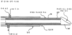
도1은 관강(lumen), 냉매 유입관 및 유출관, 관강(lumen) 내부에 형성되는 측벽구(ports)로부터 뻗어 있는 두 탐침(probes)을 가지는 전극을 나타내는, 본 발명에 따른 절개 장치의 단면도이다.1 is a cross-sectional view of an incision device in accordance with the present invention, showing an electrode having two probes extending from lumens, refrigerant inlet and outlet tubes, and sidewall ports formed inside the lumen to be.
도2(a)는, 도1의 두 냉매관의 폐쇄 루프 말단부의 단면도이다.FIG. 2 (a) is a cross sectional view of the closed loop end portion of the two refrigerant pipes of FIG.
도2(b)는 도1의 장치에 의해서 달성되는 원뿔형 절개의 투시도이다.Fig. 2 (b) is a perspective view of a conical incision achieved by the apparatus of Fig. 1.
도2(c)는 주안테나의 중앙 관강에 위치하는 페쇄 말단 및 냉각 요소를 가지는 주안테나의 단면도이다.Fig. 2 (c) is a cross sectional view of the main antenna having a closed end and a cooling element located in the central lumen of the main antenna.
도2(d)는 주안테나의 중앙 관강에 위치하는 개방 말단부 및 신장(elongated) 냉각 요소를 가지는 주안테나의 단면도이다.Fig. 2 (d) is a cross sectional view of the main antenna with an open distal end and an elongated cooling element located in the central lumen of the main antenna.
도2(e)는 도2(d)의 장치의 말단부이다.Fig. 2 (e) is the distal end of the device of Fig. 2d.
도2(f)는 2(f)-2(f) 선을 따라 취한 제 2(d) 장치의 단면도이다.2 (f) is a cross-sectional view of the second (d) device taken along the line 2 (f) -2 (f).
도3a는 선택된 조직 조직에 배치된 두 부안테나(secondery antenna)를 가지는 본 발명에 따른 다중 안테나 절개 장치의 투시도이다.3A is a perspective view of a multiple antenna dissection device according to the present invention having two secondary antennas disposed in selected tissue tissues.
도3b는 상기 두 냉매관의 폐쇄 루프 말단부에 대한 다른 실시예의 단면도이다.3B is a cross-sectional view of another embodiment of the closed loop end of the two refrigerant tubes.
도4는 4-4선을 따라 취한 도1의 단면도이다.4 is a cross-sectional view of FIG. 1 taken along line 4-4.
도5는 한 센서는 절개 부피의 외주(外周)에, 두번째 센서는 전극과 탐침 말단부 사이의 탐침 중앙점에 위치한, 4cm의 구형 절개 공간의 형성을 보여준다.Figure 5 shows the formation of a 4 cm spherical incision space, with one sensor located on the outer periphery of the incision volume and the second sensor located at the probe center point between the electrode and the probe tip.
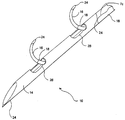
도6(a)는 전극의 말단부로부터 뻗어나온 두 탐침이 그려진, 본 발명에 따른 절개 장치의 투시도이다.Fig. 6 (a) is a perspective view of the incision apparatus according to the present invention, in which two probes extending from the distal end of the electrode are drawn.
도6(b)는 유지(retaining) 및 쥠(gripping) 기능을 제공하는 두 개의 안테나가 그려진, 본 발명에 따르는 다중 안테나 절개의 투시도이다.Figure 6 (b) is a perspective view of a multi-antenna incision in accordance with the present invention, depicting two antennas providing retaining and gripping functions.
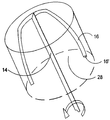
도6(c)는 유지 및 쥠 기능을 제공하는 세 개의 부안테나가 그려진, 본 발명에 따른 다중 안테나 절개의 투시도이다.Figure 6 (c) is a perspective view of a multi-antenna cutout in accordance with the present invention, depicted with three buantennas providing the retention and power functions.
도6(d)는 6(d)-6(d)선을 따라 취한 제6(c) 장치의 단면도이다.Fig. 6 (d) is a cross-sectional view of the sixth (c) device taken along line 6 (d) -6 (d).
도7는 절연 슬리브의 말단부로부터 뻗어나온 탐침을 가진, 본 발명에 따른 전극 말단부의 투시도이다.7 is a perspective view of an electrode distal end according to the present invention with a probe extending from the distal end of the insulating sleeve.
도8는 상기 전극으로부터의 네 개의 탐침 배치를 나타내는, 본 발명에 따른 절개 장치 투시도이다.8 is a perspective view of a dissection device according to the present invention, showing four probe arrangements from the electrode.
도9는 조절기, 에너지원 및 본 발명의 다른 전기적인 요소의 포함을 나타내는 블록도(block diagram)이다.9 is a block diagram illustrating the incorporation of a regulator, an energy source, and other electrical elements of the present invention.
도10는 관강(管腔,lumen), 냉매 유입관, 냉매 유출관 및 관강안에 형성된 측벽구에서 뻗어나온 두 탐침을 가진 전극을 나타내는, 본 발명에 따른 절개 장치의 단면도이다.Fig. 10 is a cross-sectional view of the cutting device according to the present invention, showing an electrode having a lumen, a refrigerant inlet tube, a refrigerant outlet tube, and two probes extending from sidewall holes formed in the lumen.
도11는 도10의 두 냉매관의 폐쇄 루프 말단부의 단면도이다.FIG. 11 is a cross-sectional view of the closed loop distal end of the two refrigerant tubes of FIG.
도12는 두 냉매관의 폐쇄 루프 말단부의 다른 실시예의 단면도이다.12 is a sectional view of another embodiment of a closed loop end of two refrigerant tubes.
도13는 4-4선을 따라 취한 도12의 단면도이다.Figure 13 is a cross sectional view of Figure 12 taken along line 4-4.
도14는 첫번째 센서는 절개 부피의 외주(外周)에, 두번째 센서는 전극과 탐침 말단부 사이의 탐침 중앙점에 위치한 4cm의 구형 절개 공간의 형성을 보여준다.Figure 14 shows the formation of a 4 cm spherical incision space located at the outer periphery of the incision volume of the first sensor and the center point of the probe between the electrode and the tip of the probe.
도15는 에너지 전달 전극의 온도를 조절하는데 유용한 피드백 시스템(feedback system)을 나타내는 블록도이다.15 is a block diagram illustrating a feedback system useful for regulating the temperature of an energy transfer electrode.
도16는 도15의 피드백 시스템을 실행하는데 유용한 회로를 보여준다.FIG. 16 shows a circuit useful for implementing the feedback system of FIG.
* 도면의 주요부분에 대한 부호의 설명* Explanation of symbols for main parts of the drawings
10,12 : 다중 안테나 절개 장치 내지 전극10,12: multi-antenna cutting device to electrode
14 : 주안테나 16 : 부안테나14: antenna antenna 16: buantenna
18 : 절연 슬리브 20 : 에너지원18: insulating sleeve 20: energy source
24 : 센서 26 : 틈(aperture)24: sensor 26: aperture
30 : 전류 센서 32 : 전압 센서30: current sensor 32: voltage sensor
40 : 냉매 유입관 42 : 냉매 유출관40: refrigerant inlet pipe 42: refrigerant outlet pipe
46 : 측벽구(sidewall port) 50,52,54 : 센서46:
t1,t2: 변압기 74,76 : 주권선(primary winding)t 1 , t 2 : transformer 74,76: primary winding
78,80 : 변압기의 부권선(secondary winding)78,80 secondary windings of transformers
86 : 펌프86: Pump
[발명의 상세한 설명]Detailed description of the invention
[기술분야][Technical Field]
본 출원은 여기에 함께 실린 고 에트 알(Gough, et al)이 1995년 8월 15일에 출원한 미국 특허 출원 No. 01/515,379 "다중 안테나 절개 장치"를 우선권으로 주장한다.This application is incorporated herein by US Patent Application No. 1 filed August 15, 1995 by Gough, et al. 01 / 515,379 "Multi-antenna incision device" is claimed as priority.
본 발명은 일반적으로 종양과 같은 신체 조직의 처리 및 절개를 위한 장치에 관한 것으로, 더욱 상세하게는 복수개의 전극을 가지는 장치에 관한 것이다.The present invention relates generally to devices for the treatment and dissection of body tissues, such as tumors, and more particularly to devices having a plurality of electrodes.
[배경기술][Background]
현재 알려진 종양 치료 절차는 극단적으로 파괴적이어서 건강한 세포 조직에 큰 손실을 유발한다. 외과 수술 도중 의사는 종양의 씨를 형성해 결과적으로 전이(轉移)를 일으키는 종양을 절개해내지 못할 것을 우려하며 수술해야 한다. 최근 몇년 사이에, 전통적인 외과 수술의 외상을 최소화 하는데 중점을 둔 여러 결과의 발달이 있었다.Currently known tumor treatment procedures are extremely destructive, causing large losses in healthy cell tissue. During surgery, the surgeon must be concerned that he will not be able to form a seed of the tumor and eventually incision the tumor that causes metastasis. In recent years, there have been several developments that have focused on minimizing the trauma of traditional surgical operations.
종양을 취급하는 도구로서 발열요법(hyperthermia) 분야에서 상대적으로 눈에 띄는 많은 활동이 있었다. 종양의 온도를 높이는 것이 암 조직의 처리 및 관리에 도움이 된다는 것은 알려져 있다. 발열요법에 의해 암 세포가 선택적으로 제거되는 메카니즘은 완전하게 이해되고 있지는 않다. 그러나, 암세포에 미치는 발열요법의 네가지의 세포학적인 효과가 제안되었으며, (i) 세포내 변화나 핵막의 투과성 및 유동성의 변화, (ii) 소화 효소 분비를 유발하는 세포질내의 리소말(lysomal)의 분해, (iii) 세포 호흡과 DNA 또는 RNA의 생성에 영향을 미치는 단백질의 열적 손상, (iv) 면역 체계의 잠재력 상승이 그것이다. 종양에 열을 가함으로써 치료하는 방법은 직접 접촉 라디오 주파수(radio-frequency, RF) 어플리케이서, 마이크로웨이브 방사(microwave radiation), 유도 복합 RF 필드, 초음파 및 여러 간단한 열전도 기술의 사용을 포함한다.There has been a relatively prominent activity in the field of hyperthermia as a tool for handling tumors. It is known that raising the temperature of the tumor helps treatment and management of cancerous tissues. The mechanism by which pyrotherapy selectively removes cancer cells is not fully understood. However, four cytological effects of pyrogenic therapy on cancer cells have been proposed: (i) alteration of intracellular or nuclear membrane permeability and fluidity, and (ii) degradation of lysomal in the cytoplasm causing digestive enzyme secretion. (iii) thermal damage to proteins that affect cellular respiration and the production of DNA or RNA, and (iv) elevated potential of the immune system. Methods of treating tumors by applying heat include the use of direct contact radio-frequency (RF) applicators, microwave radiation, inductive complex RF fields, ultrasound, and several simple thermal conduction techniques.
이러한 모든 과정과 관련된 여러 문제점 중에 하나는, 피부 표면 수 cm 밑의 깊이에 고온의 열을 아주 정확하게 집중시켜야 한다는 것이다. 마이크로웨이브나 초음파로 여러 원하는 곳에 에너지를 모으는 몇몇 기술이 개발되었다. 그러나, 일반적으로 집중 범위가 열악하므로, 결과적으로 건강한 조직이 손상된다. 또한 유도가열은 입사 에너지의 정확한 집중을 더욱 더 어렵게 한다. 비록 신체의 표면에 안테나를 위치시킴으로써 유도가열을 행할 수는 있으나, RF 전류를 사용하여 열을 유도하는 경우에 안테나 바로 옆에서 표면 와류 전류(superficial eddy currents)가 발생하고, 바람직하지 못한 표면 열이 발생하여 그 아래 조직으로 거의 열을 전달하지 못하게 된다.One of the problems associated with all of these processes is the need to concentrate the heat at a high temperature very accurately at a depth of several centimeters below the skin surface. Several techniques have been developed for collecting energy in various places with microwaves or ultrasound. However, in general, the concentration range is poor, and as a result, healthy tissue is damaged. Induction heating also makes it more difficult to accurately concentrate incident energy. Although induction heating can be done by placing the antenna on the body's surface, superficial eddy currents occur right next to the antenna when heat is induced using RF current, and undesirable surface heat And rarely transfer heat to the tissue beneath it.
따라서, 전혀 침투적이지 않게 내부 종양에 열을 제공하는 방법은, 특정되고 선택적인 처치를 달성하는데 상당한 어려움을 가지고 있다.Thus, methods of providing heat to internal tumors that are not at all invasive have significant difficulties in achieving specific and selective treatment.
RF나 마이크로웨이브원(microwave source)으로부터 생성될 수 있는 발열요법 - 45℃를 넘지 않는 - 은 세포 조직에 열을 제공하므로 보통의 세포는 살아남는다. 열치료에 있어서 45℃ 이상의 열에너지는 조직의 손상, 단백질의 탈수와 변성을 유발한다. 최근에 발열요법은 악성 종양의 치료에 더욱 더 응용되어왔다. 발열요법에 있어서는 투과성의 전류 가열로 특정 영역에 집중되는 이상 고온 상태를 유도하는 것이 바람직하며, 동시에 주위의 건강한 조직의 열적 손상을 최소화하는 것도 보장되어야 한다. 종종 종양이 피하에 위치하고 그 위치를 파악하는데 수술이나 내시경 또는 외부 복사(external radiation)가 요구된다. 전류 밀도가 건강한 조직에 의해 흡수되어 희석되기 때문에 신체 깊은 조직에 외부적으로 이상 고온을 유도하는 것은 어렵다. 게다가, RF 에너지의 일정 부분이 근육/지방, 뼈 사이에서 반사되므로 작은 종양에 필요한 양의 열을 바로 집적시키는데 더욱 문제가 있다.Exothermic therapies that can be generated from RF or microwave sources-not exceeding 45 ° C-provide heat to the tissue and the normal cells survive. In thermal therapy, thermal energy above 45 ° C causes tissue damage, protein dehydration and degeneration. Recently, fever therapy has been increasingly applied to the treatment of malignant tumors. In exothermic therapy it is desirable to induce an abnormally high temperature state concentrated in a specific area by permeable current heating, while at the same time minimizing thermal damage to surrounding healthy tissues. Often, the tumor is located subcutaneously and requires surgery, endoscopy, or external radiation. Because current density is absorbed and diluted by healthy tissue, it is difficult to induce abnormal high temperatures external to deep tissues of the body. In addition, some of the RF energy is reflected between muscle / fat and bone, which makes it more problematic to directly integrate the amount of heat required for small tumors.
투과성의 국지적 이상 고온을 이용한 시도는 그리 성공적으로 증명되지 않았다. 결과는 때때로 종양 전체를 통해 불균일한 온도를 발생해 왔다. 발열요법에 의한 종양 크기의 감소는 열 투여량(thermal dose)과 관련이 있다고 믿어진다. 열 투여량은 소정 주기의 시간동안 종양 조직 전체에 공급되는 최소 유효 온도이다. 혈액의 흐름이 종양 가열시 열 손실의 주된 기구이고, 혈액의 흐름은 종양에 따라 다르기 때문에 효과적인 치료를 보장하기 위해 종양 조직을 더욱 더 가열하는 것이 필요하다.Attempts to use permeable local abnormal high temperatures have not been very successful. The results have sometimes produced non-uniform temperatures throughout the tumor. It is believed that the reduction in tumor size by pyrotherapy is related to the thermal dose. The heat dose is the minimum effective temperature that is supplied throughout the tumor tissue for a period of time. Since blood flow is the main mechanism of heat loss during tumor heating, and blood flow varies from tumor to tumor, it is necessary to heat the tumor tissue further to ensure effective treatment.
RF 에너지를 이용한 종양 자체의 절개에 있어서도 똑같다. 종양과 같은 조직을 RF 절개하기 위해 다른 방법들이 활용되었다. 종양을 가열하는 대신에 에너지를 인가하여 절개할 수 있다. 상기 방법들은 다음과 같은 여러 인자 때문에 달성하기 곤란하다. (i) 조직 전부를 효과적으로 절개하기 위한 RF 절개 전극의 위치 선정, (ii) RF 절개 전극의 종양 위치로의 삽입, (iii) 비종양 세포의 손상없이 성공적인 절개를 달성하기 위한 RF 에너지의 모니터와 에너지 전달의 조절.The same is true for the incision of the tumor itself using RF energy. Different methods have been used to RF incision tissue such as tumors. Instead of heating the tumor, an incision can be made by applying energy. These methods are difficult to achieve due to the following factors. (i) positioning the RF incision electrode to effectively incision all of the tissue, (ii) insertion of the RF incision electrode into the tumor location, (iii) monitoring the RF energy to achieve successful incision without damaging the non-tumor cells and Regulation of energy transfer.
가장 비침투적으로 종양을 제거하기 위한 많은 다른 치료 방법과 장치들이 있다. 그러한 하나의 예로써 미국 특허 No. 4,920,978에서 게시되는, 종양안에서 RF이상 고온을 발생하는 내시경이 있다. 마이크로웨이브 내시경 장치는 미국 특허 No. 4,409,993에 설명되어 있다. 미국 특허 No. 4,920,978에서, RF 이상 고온용 내시경이 게시되어 있다.There are many other treatments and devices for the most noninvasive tumor removal. As one such example, US Pat. There is an endoscope that produces RF abnormal high temperatures in tumors, published at 4,920,978. The microwave endoscope device is US patent no. 4,409,993. U.S. Patent No. At 4,920,978, RF and higher temperature endoscopes are published.
미국 특허 No. 4,763,671(이하 "671특허"라 함)에 따르면, 종양으로 침투하여 삽입되는 두개의 카테테르(catheter)가 최소한도로 비침투적인 과정에 활용되고 있다. 상기 카테테르는 단단한 플라스틱 지지 부재를 포함한다. 상기 지지부재 주위에는 열린 그물 모양의 도체가 있다. 절연층이 접착성 구슬로 상기 도체에 부착되어 있다. 절연층이 소정의 조절 불가능한 길이를 제외하고는 상기 도체 전부를 싸고 있다. 같은 전극으로는 다른 크기를 갖는 종양을 치료할 수 없다. 관상 슬리브(sleeve)가 지지 부재내로 삽입되어 있고 방사 성능의 씨(seed)를 보유하고 있다. ’671 특허 장치는 향상된 치료를 위해 화학 치료제와 같은 유동 매질을 종양안으로 삽입하는 데는 실패하고 있다. 전극 전도성 표면의 크기도 다양하지 못하다. 또한 ‘671 특허 장치는 전압 내지 전류의 변화와 무관하게, 소정의 파워 레벨을 유지할 수도 없다.U.S. Patent No. According to 4,763,671 (hereinafter referred to as "671 patent"), two catheters that penetrate and insert into a tumor are utilized in a minimally noninvasive process. The catheter includes a rigid plastic support member. There is an open mesh conductor around the support member. An insulating layer is attached to the conductor with adhesive beads. The insulating layer covers all of the conductors except for some non-adjustable length. The same electrode cannot treat tumors of different sizes. A tubular sleeve is inserted into the support member and holds a seed of spinning performance. The '671 patent device fails to insert a fluidic medium, such as a chemotherapeutic agent, into the tumor for improved treatment. The size of the electrode conductive surface also does not vary. In addition, the '671 patent device cannot maintain a predetermined power level, regardless of the change in voltage or current.
미국 특허 No.4,565,200(이하 "200특허"라 함)에서는, 정해진 신체 부위로 삽입하기 위해 단일의 출입침 캐뉼러(cannula)가 사용되는 전극 시스템을 설명하고 있다. ‘200 특허 장치는 단일의 출입침에 국한되어 유체 주입 장치와 절연 슬리브를 포함하는 - 그러나 그에 한정되지는 않는 - 다양한 삽입체를 투입하고 제거하는데는 실패하고 있다. 게다가, ’200 특허 장치는 전류 내지 전압의 변화에 무관하게 일정한 파워를 유지하지도 못한다. 종양 내부 또는 인접 부위, 기타 다른 고체 조직에 삽입하여, 여러 전극이 상기 종양이나 고체 부분 주위에 있게 하는 장치나 방법이 필요하다.US Patent No. 4,565,200 (hereinafter referred to as "200 Patent") describes an electrode system in which a single access cannula is used to insert into a given body part. The '200 patent device is confined to a single access needle and is failing to insert and remove various inserts, including but not limited to fluid injection devices and insulating sleeves. In addition, the '200 patent device does not maintain a constant power regardless of changes in current or voltage. What is needed is a device or method that inserts into or adjacent to a tumor, or other solid tissue, such that multiple electrodes are around the tumor or solid portion.
따라서, 신체 내부로 삽입되면서 여러 전극 내지 안테나를 포함하는 절개 장치를 제공하는 것이 본 발명의 목적이다.Therefore, it is an object of the present invention to provide a cutting device including a plurality of electrodes or antennas while being inserted into the body.
본 발명의 다른 목적은 인체내에 삽입되어, 절개되어야 하는 선택 조직을 둘러싸기 위해 삽입체에 배치되는 여러 전극 내지 안테나를 가지는 절개 장치를 제공하는데 있다.Another object of the present invention is to provide an incision apparatus having several electrodes or antennas inserted into the human body and arranged on the insert to surround the selective tissue to be incision.
본 발명의 또다른 목적은 피드백 조절을 포함하는, 배치된 다중 전극 내지 안테나를 가지는 절개 장치를 공급하는데 있다.Another object of the present invention is to provide an incision apparatus having arranged multiple electrodes or antennas, including feedback adjustment.
본 발명의 또다른 목적은 하나 내지 그 이상의 열센서를 가지는, 배치된 여러 전극 내지 안테나를 가지는 절개 장치를 제공하는데 있다.Another object of the present invention is to provide a cutting device having several electrodes or antennas arranged, having one or more thermal sensors.
본 발명의 또다른 목적은 냉각 수단을 가지는, 배치된 여러 전극 내지 안테나를 가지는 절개장치를 제공하는 것이다.It is a further object of the present invention to provide a dissection device having several electrodes or antennas arranged, with cooling means.
본 발명의 또 다른 목적은 저해하지 않는, 배치된 여러 전극 내지 안테나를 가지는 절개장치를 제공하는데 있다.It is still another object of the present invention to provide an incision apparatus having a plurality of electrodes or antennas arranged, which do not inhibit.
상기 목적 및 다른 목적은 다중 안테나 장치를 구비하는 절개 치료 장치로 달성된다. 상기 다중 안테나 장치는 관강, 종축 및 L1길이의 절개 표면 영역을 가지는 주안테나를 포함한다. 상기 다중 안테나 장치는 또한 상기 주안테나가 조직을 통해 도입되는 때에는 상기 주안테나내에 위치하는 부안테나를 포함한다. 부안테나 말단부는 상기 주안테나 관강으로부터 그 종축에 대해 횡방향으로 선택된 조직 영역에서 전개된다. 센서가 주안테나로부터 부안테나 말단부를 따라 거리 L2에서 부안테나 말단부의 외곽에서 적어도 부분적으로 위치한다. L2는 적어도 1/3L1과 동등하다. 에너지원이 상기 주안테나에 연결된다.This and other objects are achieved with an incision treatment device having multiple antenna devices. The multi-antenna device comprises a main antenna having a lumen, longitudinal axis and an incision surface area of L 1 length. The multi-antenna device also includes a sub antenna located within the main antenna when the main antenna is introduced through the tissue. The buantenna distal end develops in a tissue region selected transverse to the longitudinal axis from the main antenna lumen. The sensor is located at least partially outside the subantenna end at a distance L 2 from the main antenna along the subantenna end. L 2 is equal to at least 1/3 L 1 . An energy source is connected to the main antenna.
[실시예]EXAMPLE
도1에서 보여지듯이 절개 치료 장치 10은 길이의 조절이 가능한 다중안테나장치 12를 포함한다. 다중안테나장치 12는 조절 가능하거나 불가능한 에너지 전달표면 또는 길이를 갖는 주안테나 14를 포함하며, 주안테나에서 적어도부분적으로 형성된 관강으로부터 전형적으로 삽입된 하나 또는 그 이상의 부안테나를 갖는다. 각각의 부안테나 역시 조절 가능하거나 또는 불가능한 에너지 전달 표면 또는 길이를 갖는다. 길이의 조절 가능 정도는 목표된 조직을 여러 기하학적 형태로 절개하는 것을 가능하게 한다. 주안테나 및 부안테나 14, 16의 길이는 조절할 수 있으며, 주안테나 14는 반드시 대칭성은 아닌 다양한 기하학적 형태로 조직을 절개하고, 센서와 함께 절개된 조직의 경계를 한정하기 위해 위 아래, 종축 주위로 회전, 앞 뒤로 움직여진다.As shown in Figure 1
주안테나 내지 전극 14는 고체 조직 내부로 관통하거나 복강경처럼 삽입될 수 있는 구조로 구성된다. 주안테나 14는 고체 조직으로의 삽입을 돕기 위해 날카로운 말단부를 가질 수도있다. 각각의 부안테나16는 구조적으로 주안테나 14보다 덜 단단하게 만들어진다. 이는 다음과 같은 방법으로 달성된다. (i) 주, 부안테나 14 및 16의 재료를 다르게 선택하거나, (ii) 같은 재료이더라도 부안테나에는 더 적은 재료를 포함시키는, 예컨데 부안테나를 주전극보다 덜 두껍게 하거나 다양한 구조적 단단함을 갖도록 14 또는 16 안테나의 하나에 또다른 물질을 포함시킨다. 상기 게시에서, 구조적 강도(rigidity)는 안테나가 자신의 종축(longitudinal axis)에 대해 상대적으로 휘는 양으로 정의된다. 주어진 안테나는 자신의 길이에 따라 다른 강도의 정도를 가질 것이라고 예상된다. 주안테나와 부안테나는 금속성 내지 비금속성인 경우 모두, 다양한 전도성 물질로 만들어질 수 있다. 하나의 적당한 재료로는 피하 주사의 재질을 가진 타입 304 스테인레스강이 있다. 주안테나 14의 강도는 부안테나 16보다 크다. 응용에 따라 부안테나 16의 강도는 주안테나 14 강도의 약 10%, 25%, 50%, 75% 및 90%일 수 있다. 주, 부안테나 14, 16은 금속성이거나 아닌 경우 모두, 다양한 전도성의 물질로 만들어질 수 있다. 몇몇 응용의 경우에는 두번째 전극 16은 캘리포니아 멘로 파크 (California Menlo Park)에 있는 레이켐 코포레이션(Raychem Corporation)에 의해 상업적으로 활용된 NiTi 같은, 형상 기억 금속(shaped memory metal)으로 만들어질 수 있다.The main antenna to the
주안테나 14 내지 부안테나 16 각각은 다른 길이를 가질 수 있다. 적당한 길이는 17.5cm, 25.0cm, 30.0cm 이나 이에 국한되지는 않는다. 안테나의 실제적 길이는 의사가 복강경, 피부관통, 또 다른 과정중 어느 것을 택하느냐 아니냐 뿐만 아니라, 절개될 목표 고체 조직의 위치, 피부로부터의 거리, 접근 가능성(accessibility)에도 좌우된다. 또한, 절개 치료 장치 10, 더 상세하게 다중 안테나 장치 12는 가이드를 통해 원하는 조직 영역으로 삽입될 수 있다.Each of the
절연 슬리브 18은 주안테나와 부안테나 14, 16 각각은 하나 내지 둘 모두의 외곽 주위에 위치된다. 바람직하게는, 각각의 절연 슬리브는 절개 전달 표면을 제공하는 안테나의 길이가 다양하게 변할 수 있도록 하기 위해 조절 가능하게 위치한다. 주안테나 14를 둘러싼 각 절연 슬리브 18은 하나 내지 그 이상의 틈(aperture)을 포함할 수 있다. 이는 주안테나 14와 절연 슬리브 18을 통해 부안테나 16이 삽입되는 것을 허용한다. 절연 슬리브로부터 뻗어나오는 부안테나의 길이는 말단부 16‘의 길이를 결정한다.The insulating
하나 내지 그 이상의 센서 24는 주안테나 14, 부안테나 16 또는 절연 슬리브 18의 내부 또는 외부 표면에 위치한다. 바람직하게는, 센서 24는 주안테나 말단부 14‘와 부안테나 말단부 16’ 및 절연 슬리브 말단부 18‘에 위치한다. 부안테나 16은 절연 슬리브 말단부 18’로부터 주안테나 14의 횡방향으로 뻗어나갈 수 있고, 센서 24는 절연 슬리브 말단부 18‘에 위치할 수 있다. 바람직하게는, 센서 24는 말단부 16‘의 외부표면에 적어도 부분적으로 위치된다.One or
L1은 주안테나 14의 전자기 에너지 전달 표면의 길이이다. L2는 센서가 말단부 16‘의 적어도 외곽에 부분적으로 위치하는 경우 주안테나 14로부터 센서 24까지의 거리이다. L2는 말단부 16’의 표면을 따라 주안테나 14로부터 측정된다. 여러 실시예에서, L2의 길이는 L1의 33.33%, L1의 50%, L1의 75% 및 L1과 같은 길이와 적어도 같거나 더 크다.L 1 is the length of the electromagnetic energy transfer surface of the
일 실시예에서 절연 슬리브는, 폴리아미드 절연체의 맨위에 위치한 센서와 0.002인치 수축랩(shrink wrap)을 가지는, 폴리아미드 재료로 구성될 수 있다. 폴리아미드 절연층은 반고체이다. 상기 센서가 폴리아미드의 전체 길이를 실질적으로 정한다.In one embodiment, the insulating sleeve may be comprised of a polyamide material, having a 0.002 inch shrink wrap with a sensor located on top of the polyamide insulator. The polyamide insulation layer is semisolid. The sensor substantially defines the overall length of the polyamide.
본 발명은 다중 안테나 절개 장치를 제공한다. 장치는 전자기 에너지원, 말단부를 가지는 투관침(trocar), 투관침의 종축을 따라 속이 빈 관강(管腔, lumen), 세개 내지 그 이상의 안테나를 가지는 다중 안테나 절개 장치를 포함한다. 상기 안테나들은 투관침이 조직이 삽입될 때는 우선 투관침 관강 내부에 위치한다. 선택된 조직 위치에서 상기 안테나들은 투관침 관강의 종축에 대해 횡방향으로 배치될 수 있다. 배치된 각 상기 안테나는 다음을 형성하는데 충분한 크기의 전자기 에너지 전달 표면을 갖는다 (i) 배치된 안테나 사이에서 부피를 가지는 절개를 형성하고, (ii) 전자기 에너지원으로부터 다중 안테나 절개 장치로 10 내지 50 와트의 전자기 에너지가 전달될 때 배치된 안테나의 그 어느 것도 저해됨이 없이 부피를 가지는 절개를 형성한다. 적어도 하나의 케이블이 다중 안테나 절개 장치와 전자기 에너지원을 연결한다. 이 명세서에서 "저해됨 (impeding out)"이란 용어는 조직 위치가 충분히 건조되고 탄화되어, 상기 건조되고 탄화된 조직 위치가 응고 조직을 형성하는 과정을 손상시키는 결과적인 높은 전기 저항을 가지게 됨을 의미한다.The present invention provides a multi-antenna cutting device. The device includes an electromagnetic energy source, a trocar having a distal end, a hollow lumen along the longitudinal axis of the trocar, and a multi-antenna cutting device having three or more antennas. The antennas are first placed inside the trocar lumen when tissue is inserted. At the selected tissue location the antennas may be positioned transverse to the longitudinal axis of the trocar lumen. Each of the antennas arranged has an electromagnetic energy transfer surface of sufficient size to form (i) a volumetric incision between the deployed antennas, and (ii) from a source of electromagnetic energy to a multi-antenna cutting device. When the watts of electromagnetic energy are delivered, a bulky incision is made without disturbing any of the deployed antennas. At least one cable connects the multiple antenna cutting device with the electromagnetic energy source. The term "impeding out" in this specification means that the tissue location is sufficiently dried and carbonized so that the dried and carbonated tissue location has a resulting high electrical resistance that impairs the process of forming coagulated tissue.
에너지원 20은 하나 내지 그 이상의 케이블 22에 의해 다중 안테나 장치 12에 연결된다. 에너지원 20은 RF원, 마이크로웨이브원, 단파원, 간섭성이거나 비간섭성인 초음파원등이 될 수 있다. 다중 안테나 장치 12는 RF 안테나, 마이크로웨이브 안테나, 또는 그들의 조합인 주안테나 및 부안테나 14와 16으로 구성될 수 있다. 하나의 실시예에서는 에너지원 20은 조합 RF/마이크로웨이브 박스이다. 부가적으로 레이저원 20과 연결된 레이저 광섬유가 주, 부안테나 14와 16중 하나 내지 둘 모두를 통해 삽입될 수 있다. 하나 내지 그 이상의 주안테나 14 또는 부안테나 16는 광섬유를 삽입하기 위한 가지로 사용될 수 있다.
안테나 14 및 16 각각은 전자기적으로 에너지원 20과 연결된다. 연결은 에너지원 20으로부터 각 안테나 14 및 16으로 직접 될 수도 있고, 안테나 14와 16을 에너지원 20에 연결시키는 콜레트(collet)나, 슬리브 같은 것을 사용하여 간접적으로 될 수도 있다.
하나 내지 그 이상의 센서 24는 주안테나 14, 부안테나 16, 절연 슬리브 18의 내부 또는 외곽 표면에 위치한다. 바람직하게는, 센서 24는 주안테나 말단부 14‘, 부안테나 말단부 16’및 절연 슬리브 말단부 18‘에 위치한다. 센서 24는 다음의 사항을 결정하기 위해 필요한 조직 위치에서의 온도를 정확하게 측정하게 해준다. (i) 절개의 범위, (ii) 절개의 양, (iii) 더이상의 절개가 필요한지 아닌지, (iv) 절개 조직의 경계나 외주(外周). 더우기 센서 24는 목표가 아닌 조직이 파괴되거나 절개되는 것을 방지한다.One or
센서 24는 서미스터(thermistors), 열전지(thermocouples) 및 저항선 등을 포함하지만 그에 국한되지는 않는, 전통적인 디자인이다. 적당한 열센서 24는 구리 콘스탄탄(constantene)을 가지는 T 타입 열전지, J 타입, E 타입, K 타입, 광섬유, 저항선, 열전대 적외선 탐지기 같은 것들을 포함한다. 센서 24는 열센서일 필요는 없을 것으로 평가된다.
센서 24는 모니터해서 너무 많은 조직을 파괴하지 않고 적당한 정도의 절개가 달성될 수 있게 온도 및/또는 임피던스를 측정한다. 이는 절개되는 목표 부분 주위를 싸는 조직의 손상을 줄여준다. 선택된 부분의 내부 다양한 지점의 온도를 모니터함으로써 언제 절개가 끝날 지 결정될 뿐 아니라, 종양 외주도 결정될 수 있다. 만약 센서가 적당한 절개 온도를 초과했다고 결정하면, 적당한 피드백 신호가 에너지원 20에 접수되고 이어 주안테나 및/또는 부안테나로 전달되는 에너지의 양을 조절한다.
따라서, 절개되는 모양(geometry)은 선택 가능하며 조절 가능하다. 많은 다른 절개 모양이 달성될 수 있다. 이는 센서 24를 포함할 뿐 아니라, 주안테나 14의 절개 표면과 부안테나 16의 절개 표면이 다양한 길이를 가지는 결과이다.Thus, the geometry to be cut is selectable and adjustable. Many different incision shapes can be achieved. This includes not only the
더욱 바람직하게는, 부안테나 16이 주안테나 14에 형성된 틈 26의 바깥으로 횡방향으로 배치된다. 틈 26은 전형적으로 주안테나 14의 종축을 따라 위치한다.More preferably, the
먼저 주안테나 14가 목표인 고체 조직 내부 또는 인접한 곳에 삽입된다. 부안테나가 틈 26 밖으로 나와 고체 조직속으로 삽입된다. 부안테나 16의 휘는 양은 아주 다양하다. 예컨데, 주안테나 14의 종축으로부터 몇 도(°)정도 휠 수 있다. 또는 부안테나는 후크 “7”을 포함하나 그에 한정되지 않는 많은 종류의 기하학적 형태로 휠 수 있다. 더우기, 부안테나는 주안테나로부터 수 mm정도 삽입될 수도있고, 또는 더 큰 거리만큼 삽입될 수도있다. 부안테나에 의한 절개는 주안테나로부터 수 mm 떨어져 시작할 수 있고, 또는 주안테나로부터 더 많은 거리를 진행하여 그 지점에서 부안테나에 의한 초기 절개를 시작할 수도있다.First,
도2(a)에 나타난 바와 같이, 주안테나 14는 선택된 조직 또는 종양 28 속으로 삽입되었다. 이어서, 부안테나 말단부 16‘이 틈 26 밖으로 나와 선택된 조직 28 안으로 진행한다. 센서 24는 말단부 16’에 위치한다. 절연 슬리브도 포함될 수 있고, 상기 절연관은 고정되거나 조절 가능할 것이다. RF, 마이크로웨이브, 단과 같은 에너지가 주안테나 14 및 부안테나 16 둘 모두 또는 오직 하나에만 전달된다. 안테나 14 내지 16 둘 중 하나는 활동하거나 활동하지 않을 수 있다. 부안테나가 활동하는 경우, 주안테나 말단부 14‘이 센서 24를 포함한다. 상기 실시예의 경우에, L1은 말단부 16’의 전자기 에너지 전달 표면의 길이이며, L2는 말단부 14‘의 맨 끝으로부터 주안테나 14에 위치한 부안테나 16이 횡으로 뻗어나온 출입구(port)까지의 거리이다. 안테나 14 및 16은 단극 모드(RF)에서 작동하거나 또는 양자 중 택일적으로 작동된다. 다중 안테나 장치 12는 이중극 모드(RF)에서 작동될 수 있다. 다중 안테나 장치 12는 단극 및 이중극 작동 사이에서 스위칭될 수 있고, 안테나 14 및 16 사이에서 다중 송신 기능을 가진다. 부안테나 말단부 16’이 주안테나 14의 내부로 들어가고, 그 다음 주안테나가 회전된다. 그 후 부안테나 말단부 16‘이 선택된 조직 28로 삽입된다. 부안테나는 작은 영역을 절개하기 위해 선택된 조직 28 속으로 짧은 거리 삽입될 수도있다. 그리고 더 넓은 절개 범위를 형성하기 위해 수배의 거리를 더 진행할 수도 있다. 다시, 부안테나 말단부 16’은 주안테나 14로 복귀한다.As shown in FIG. 2 (a),
또한 도2(a)에 나타난 바와 같이, 주안테나 14는 선택된 조직 28 속으로 삽입되었다. 이어서, 부안테나 말단부 16‘이 틈 26 밖으로 나와 선택된 조직 28 안으로 진행한다. 센서 24는 말단부 16’에 위치한다. 절연 슬리브도 포함될 수 있고, 고정되거나 조절 가능할 것이다. RF, 마이크로웨이브, 단파 같은 에너지가 주안테나 14, 부안테나 16, 또는 오직 하나에만 전달된다. 안테나 14나 16 둘 중 하나는 활동하거나 활동하지 않을 수 있다. 부안테나가 활동하는 경우, 주안테나 말단부 14‘가 센서 24를 포함한다. 이 경우에, L1은 말단부 16’의 전자기 에너지 전달표면의 길이이며, L2는 말단부 14‘의 맨 끝으로부터 주안테나 14에 위치한 부안테나 16이 횡으로 뻗어있는 출입구(port)까지의 거리이다. 안테나 14 및 16은 단극 모드(RF) 에서 작동하거나 또는 양자 중 택일적으로 작동된다. 다중 안테나 장치 12는 이중극 모드(RF)에서 작동될 수 있다. 다중 안테나 장치 12는 단극 또는 이중극 작동 사이에서 스위칭될 수 있고, 안테나 14 및 16 사이에서 다중 송신 기능을 가진다. 부안테나 말단부 16’이 주안테나 14의 내부로 들어가고, 그 다음 주안테나가 회전된다. 그러면 부안테나 말단부 16‘이 선택된 조직 28로 삽입된다. 부안테나는 작은 영역을 절개하기 위해 선택된 조직 28속으로 짧은 거리 삽입될 수도 있다. 그리고 더 넓은 절개 범위를 형성하기 위해 수배의 거리를 더 진행할 수도 있다. 다시, 부안테나 말단부 16'은 주안테나 14로 복귀한다.As also shown in Figure 2 (a), the
더 넓은 절개 범위를 형성하기 위해 수 배의 거리로 종양 28 내부로 더 진행할 수 있다. 다시, 부안테나 16은 주안테나 14로 복귀하고, 주안테나 14는 (i) 다시 회전하고, (ii) 부안테나 16이 주안테나 안밖으로 삽입되거나 복귀하는 또 다른 일련의 절개를 시작하기 위해 종양 28의 종축을 따라 이동하고, (iii) 종양 28로 부터 제거될 수 있다. 이런 많은 요소들 때문에, 다양한 길이 절개면들이 있는 주, 부안테나 14, 16 및 센서 24의 이용을 가지는 일련의 절개를 포함하는 여러 다른 자취와 형태의 종양 조직 절개가 가능해진다.The tumor can be further advanced into
도2(b)에 나타난 바와 같이, 주안테나 14는 하나 내지 그 이상의 냉각 요소 27을 포함할 수 있다. 냉각 요소를 삽입하기 위한 순환 시스템과 연결된, 밀폐되고 신장된 구조 27‘이 적당한 냉각 요소 27의 한 실시예이다. 두 개의 관강이 주안테나 14나 부안테나 16에 편입되어 안테나 14, 16 쪽으로 또는 멀리 냉매를 운반하게 된다. 한 실시예에서는 관강들의 크기는; 외부 관강은 0.117인치의 외부 직경과 0.088인치의 내부 직경을, 내부 관강은 0.068인치의 외부 직경과 0.060의 내부 직경을 갖게 한다. 냉매는 주안테나 14에 들어가서, 주안테나를 둘러싼 조직에서 발생한 열을 흡수하고 그후에는 가열된 매질이나 안테나 14 내부에 존재하게 된다. 이는 두 관강의 사용; 즉 한 관강이 냉매를 도입하고 다른 관강이 가열된 냉각 용액을 제거함으로써 달성된다. 이어서, 가열된 매질로부터 열이 제거되고 다시 냉각된 매질이 안테나 14를 통해 재순환하게 된다. 이는 연속적인 과정이다. 냉각 요소 27은 절개 에너지 전달 표면을 갖는 안테나 14의 단면을 따라서만 위치될 필요가 있으며 이로써 냉각기능을 제공한다. 절연 슬리브 18은 주안테나 14의 길이를 따라 미끄러지는 조절이 가능하거나, 또는 고정된 위치를 가질 수도 있다. 절연 슬리브 18로 싸여있지 않은 주안테나의 외곽이 절개 에너지 전달면을 제공한다. 인접한 조직으로 전달된 전자기 에너지로부터 가열되고 타게 되는 유일한 표면이 바로 이 표면이다. 따라서 안테나 14의 상기 표면을 냉각할 필요만 있으며, 냉매 17에 의한 냉각은 절개 에너지 전달표면에 국한될 수 있다.As shown in FIG. 2 (b), the
냉매는 에칠알콜, 프레온, 폴리디메틸실록산과 같은 것들로, 그러나 그에만 한정되지는 않는 것들이 될 것이다. 냉각은 역시 줄-톰슨 효과에 의한 가스 팽창 냉각으로 달성될 수 있다.Refrigerants will be such as, but not limited to, ethanol, freon, polydimethylsiloxane. Cooling can also be achieved with gas expansion cooling by the Joule-Thomson effect.
냉각 요소 27의 또 다른 실시예에서는, 말단부 14‘는 역시 폐쇄되어있고, 냉매가 안테나 14에 형성된 중앙 관강을 통해 흐른다. 냉매 27은 펌프를 가진 열교환기와 같은 재순환 시스템과 연결된다. 주안테나 14를 통하는 유체의 흐름율은 많은 다른 변수에 기초하여 다양하다.In another embodiment of the
또 다른 실시예에서는, 냉각 요소 27은 신장된 구조 27“를 통해 흐르는 냉매를 가지는, 실린더 같은 관형 부재를 포함하는 - 그러나 그에 한정되지 않는 - 신장된 구조 27”로 표현된다.(도2(c)) 신장된 구조 27“는 주안테나 14의 중앙 관강 내부에 위치하고 말단부 14‘까지 뻗칠 수 있다. 말단부 14’는 폐쇄되어 있거나 개방되어 있다. 냉매는 신장된 구조 27”안에 국한된다. 이로써 주안테나 14의 속이 빈 관강을 통해 다른 매질을 삽입하고 흐르게 할 수 있다. 부안테나 16는 말단부 14‘에서 나갈 수 있으며, 또는 양자 택일적으로, 안테나 14의 옆을 따라 나올 수도 있다.(도2(d))In another embodiment, the
냉각요소 27를 통한 유체의 흐름은 첫번째 출입구(port)를 통해 유입되고 두번째 출입구를 통해 나간다.(도2(e))The flow of fluid through the
다양한 다른 냉매로써 가스, 차가운 공기, 냉각 공기, 압축 공기, 프레온, 물, 알콜같은 것을 사용할 수 있으나 이에 한정되지는 않는다. 또한, 냉각 요소 27은 주안테나를 한정하는 벽 속에 편입될 수 있으며, 주안테나 외곽에 위치할 수도있다. 바람직한 냉각 효과는 냉매의 재순환없이 달성될 수 있다. 냉각 장치(chiller) 역시 유용할 수 있다. 냉매의 흐름율과 온도의 조합이 적당한 정도의 냉각을 달성하는데 중요하다.Various other refrigerants may be used such as, but not limited to, gas, cold air, cooling air, compressed air, freon, water, alcohol. In addition, the
냉각양이 증가할수록, 더 많은 RF 에너지 효과들이 넓은 영역에 걸쳐 분포될 수 있다. 안테나 14와 16에 인접한 조직이 절개되는 절개의 마지막까지 냉각이 제공되고 조절된다. 조직에 미치는 RF 복사 효과는 냉각 전도효과에 의해 조절된다.As the amount of cooling increases, more RF energy effects can be distributed over a wide area. Cooling is provided and controlled until the end of the incision where tissue adjacent to
냉각요소 27은 주안테나 14에서 실행된 바와 같이, 부안테나 16에도 포함될 수 있다.The
주안테나 14 내지 부안테나 16을 통해 전달된 전자기 에너지는, 절개 에너지 전달 표면을 가지는 안테나에 인접한 조직을 가열하고, 그 열을 안테나 14 및 16에 돌려주는 현상을 초래한다. 더욱 더 많은 열이 제공되고 돌려받아지면, 안테나 14 및 16의 타는 효과(charring effect)도증가한다. 이는 안테나를 통한 전자기 에너지 전도도의 손실로 귀착할 수 있다. 냉각 요소 27의 포함은 목표된 부분에로의 전자기 에너지의 유효한 전달에 영향을 미치지 않는다. 냉각 요소 27은 안테나 14와 16에 인접한 조직의 열을 제거하거나 감소시키면서, 목표된 부분 전체를 절개하도록 해준다. 냉각은 노출된 안테나 14 및 16의 표면이 있는 곳에서만 필요하다.Electromagnetic energy delivered through the
도3(a)에서 보여진 바와 같이, 절개 치료 장치는 주안테나 14의 종축을 따른 여러 다른 위치에 따라 독립적으로 또는 종속적으로 횡으로 배치될 수 있는, 둘 또는 그 이상의 부안테나 16을 포함할 수 있다. 각 부안테나 16은 주안테나 14의 몸체에 형성된 분리된 틈 26(aperture)으로부터 진행되어 있다. 여러 부안테나들 16은 모두 같은 평면을 따라 삽입될 수도있고, 복수 평면 또는 그 둘의 조합을 이룰 수도있다.As shown in FIG. 3 (a), the incision treatment device may include two or more sub-antennas 16, which may be disposed transversely or independently depending on different positions along the longitudinal axis of the
도3(b)에서, 두 개의 부안테나 16은 각각 말단부 14‘밖으로 배치되어 있고 선택된 조직 부분 28으로 삽입된다. 부안테나들 16은, 주안테나 14 및 부안테나 16의 절개 표면 사이에 펼쳐진 절개면과 절개 영역을 형성한다. 주안테나 14는 선택된 조직 부분에 인접한 관계로 삽입된다. 이러한 특별한 배치는 작은 선택 조직 조직 28이나, 관통된 선택 조직 28이 바람직하지 않는 곳을 위해 유용하다. 부안테나 16이 주안테나 14의 중앙 관강안으로 복귀하면서, 주안테나는 회전할 수 있고, 두 부안테나 사이에 한정된 또 다른 절개 공간이 형성된다. 또 주전극 14는 선택 조직 부분 28과 인접한 초기 지점으로부터 후퇴하여 선택 조직 부분 28에 인접한 또 다른 지점에 자리잡을 수 있으며, 배치된 부안테나 16은 다른 절개 사이클을 시작한다. 여러 다양한 다른 위치 선정은 다른 기하학적 구조나 크기의 선택 조직의 바람직한 절개 구조를 형성시킨다.In FIG. 3 (b), two
구형 절개의 형성이 도4에 나타나 있고, 원통형 절개의 형성은 도5에 나타나 있다.The formation of a spherical incision is shown in FIG. 4, and the formation of a cylindrical incision is shown in FIG. 5.
도6(a)에서, 탐침 24와 26은 각각 전극 12 말단부 바깥으로 배치되고 선택조직으로 삽입된다. 탐침 24와 26은 평면을 형성한다.In Figure 6 (a), probes 24 and 26 are placed out of the 12 ends of the electrodes and inserted into the selective tissue, respectively.
도6(b) 및 도6(c)에 나타낸 바와 같이, 안테나 16은 다중 안테나 장치 12를 선택 조직안에 부착(anchoring)시키는 부가적인 기능을 제공할 수 있다. 도6(b)에서는 하나 내지 두 개의 안테나 16이 주안테나를 고정시키거나 투관침 14를 위치시키는데 사용되고 있다. 더우기, 하나 또는 두 개의 부안테나 16은 또한 조직을 절개하는 데도 사용된다. 도6(c)에서는 세 개의 안테나가 배치되어 주안테나 또는 투관침 14를 부착시킨다.As shown in Figures 6 (b) and 6 (c), the
도6(d)는 다중 안테나 장치 12의 주입 능력을 나타내고 있다. 세 개의 안테나 16이 투관침 14의 중앙 관강 14" 안에 위치한다. 하나 또는 그 이상의 안테나 16은 또한 주입 원료와 연결된 중앙 관강을 가질 수 있다. 중앙 관강 14”는 주입 원료에 연결되어 다양한 주입 물질을 목표 절개 조직 내외부의 선택된 위치에 전달한다. 적당한 주입 물질은 치료 약품, 전도도 향상 물질, 항생 물질이나 염료같은 것을 포함하나 이에 한정되지는 않는다. 치료 약품의 하나의 예는 화학 치료제이다.6 (d) shows the injection capability of the
도7에서와 같이 절연 슬리브 18은 절연 슬리브 18 말단부 밖으로 배치된 추가적인 탐침뿐 아니라 부탐침 24, 26을 접수하기 위한 하나 또는 그 이상의 관강을 포함할 수 있다.As shown in FIG. 7, the insulating
도8은 전극 12 몸체에 형성된 여러 다른 측벽구 바깥으로 삽입되어 있는 네개의 탐침을 나타낸다. 일부 내지 전부의 탐침은 부착 기능을 제공한다.FIG. 8 shows four probes inserted out of various other sidewall holes formed in the
도9에 의하면 주안테나 14 및 부안테나 16을 통해 전달된 전류는 전류 센서 30으로 측정된다. 전압은 전압 센서 32로 측정된다. 임피던스와 파워는 파워 및 임피던스 계산 장치 34에서 계산된다. 그러면, 이 수치는 사용자 인터페이스나 디스플레이에 표시된다. 파워나 임피던스 수치를 나타내는 신호는 조절기 38에 의해 접수된다.Referring to FIG. 9, the current delivered through the
일 실시예에서는, 절개 장치는 손잡이, 손잡이 말단부로부터 펼쳐진 전극, 탐침, 열센서와 에너지원을 포함한다. 전극은 말단부와 관강, 냉매 유입관과 냉매 유출관을 포함한다. 이 두 유출입관은 전극 관강을 따라 전극 말단부까지 뻗어 있다. 유출입관을 흐르는 냉매와 격리되어 있는 측벽구는 전극 안에 형성된다. 탐침은 적어도 전극 관강에 부분적으로 위치하며 측면 틈쪽으로 또는 바깥쪽으로 진행하거나 수축하는 형상을 가진다. 열센서는 탐침에 의해 지지된다. 전극은 에너지원과 연결된다.In one embodiment, the incision device comprises a handle, an electrode extending from the handle end, a probe, a thermal sensor and an energy source. The electrode includes a distal end and a lumen, a refrigerant inlet tube and a refrigerant outlet tube. These two outflow tubes extend along the electrode lumen to the electrode end. A sidewall hole is isolated from the refrigerant flowing through the inlet and outlet pipe is formed in the electrode. The probe is at least partially located in the electrode lumen and has a shape that travels or contracts toward or out of the lateral gap. The thermal sensor is supported by the probe. The electrode is connected to an energy source.
도10에서 보이는 바와 같이, 절개 장치 10은 손잡이 11, 전극 14, 냉매 유입관 40, 냉매 유출관 42 및 말단부에 붙어서 밀폐된 냉각 시스템을 형성하는 덮개(cap) 44를 가진다. 다양한 다른 냉매로는 가스, 찬 공기, 냉각 공기, 압축 공기, 프레온, 물, 알콜, 염수같은 것을 포함하나 그에 한정되지는 않는다. 첫번째 측벽구 46은 안테나 14의 측면에 형성된다. 두번째 측벽구 역시 포함될 수 있다. 첫번째 또는 두번째 측벽구는 안테나 14에 기계적으로 약한 지점을 만들어내는, 안테나 14에 형성된 창문들이다. 첫번째 탐침 24는 전극 내부에 위치하며, 첫번째 측벽구 쪽으로 수축하거나 바깥쪽으로 진행할 수 있다. 선택적인 두번째 탐침 26도 전극 관강 내부에 위치하며 두 번째 측벽구를 통해 옆의 선택 조직을 절개하기 위해 진행하거나 수축할 수 있다.As shown in FIG. 10, the cutting
안테나 14는 선택된 절개 조직으로 전자기 에너지를 전달하는 외부 절개 에너지 전달 표면을 갖고, 점차 가늘어지거나 날카로와지는 말단부를 가질 수도있다. 종양의 절개를 위해, 0.25인치 또는 이보다 다소 작은 길이의 외부 절개 에너지 전달 표면을 가지며, 안테나 14의 외부 직경은 약 0.072인치나 이보다 다소 작은 값을 가질 수 있다.
각 탐침 24와 26은 스테인레스강, 형상 기억 금속과 같은 - 그러나 그에 한정되지 않는 - 다양한 재료로 형성될 수 있다. 탐침 24와 26의 크기는 의료 응용에 따라 다양하다. 종양의 취급을 위해, 탐침 24와 26은 측벽구로부터 조직으로 3cm 또는 이보다 다소 작게 뻗은 길이를 갖는다. 첫번째 센서 50은 탐침 24에 의해 내부 또는 외부 표면에 지지될 수 있다. 바람직하게는 첫번째 센서 50은 탐침의 말단부에 위치한다. 두번째 센서 52는 안테나 14 외부 표면과 탐침 24 말단부 사이의 중간인 탐침 24 위 어느 지점에 위치한다. 더 바람직하게는, 두번째 센서 52는 선택된 조직 절개부피 가운데서 온도를 감지할 수 있게 하는 지점에 위치한다. 두번째 센서 50는 탐침 24이 혈관 같은 방해물을 만난 경우에 절개 과정을 결정하는데 유용하다. 만약 첫번째 센서 50이 두번째 센서 52보다 높은 온도를 측정하면, 이는 두번째 센서 52가 순환하는 혈관에 가까움을 나타낸다. 이 경우에는, 절개 에너지가 혈관에 의해 멀리 옮겨진다. 유사하게, 두번째 탐침 26도 하나 내지 그 이상의 센서를 포함할 수 있다. 세번째 센서 54는 안테나 14의 외부 표면에 위치할 수 있다.Each
센서 50, 52, 54는 (i) 절개의 범위 (ii) 절개의 양, (iii) 더 이상의 절개가 필요한지 아닌지, (iv) 절개된 조직의 경계나 외주 등을 결정하기 위해 조직 위치의 온도를 정확하게 측정하게 해준다. 적당한 열센서로는 구리 콘스탄탄(constantene)을 가진 T 타입 열전지, J 타입, E 타입, K 타입, 광섬유, 저항선, 열전대 IR 탐지기 같은 것을 포함하나 그에 한정되지는 않는다.
센서 50, 52 및 54는 너무 많은 조직의 파괴없이 바람직한 단계의 절개를 달성하고 모니터하기 위해 온도 및/또는 임피던스를 측정한다. 이는 절개되어야 하는 목표 조직을 둘러싸는 조직의 손상을 감소시킨다. 선택된 조직의 내부 다양한 지점의 온도를 모니터함으로써, 절개가 끝난 시기를 결정할 뿐 아니라 선택 조직의 외주(periphery)의 결정이 이루어진다. 만약, 센서 50, 52 및 54가 바람직한 절개 온도를 초과한다고 결정한 때에는, 그 이후에 적당한 피드백 신호가 에너지원 20에 접수되고, 이후에 더 완전히 설명되어질 바와 같이, 안테나 14로 전달되는 에너지의 양을 조절한다.
안테나 14는 전선, 납땜, 보통의 커플릿(couplet)으로의 연결과 같은 방법에 의해 전자기 에너지원 20에 연결된다. 안테나 14는 탐침 24 및 26으로부터 전자기 에너지원 2-으로 독립적으로 연결될 수 있다. 안테나 14와 탐침 24 및 26은 다중 송신 장치일 것이며, 따라서 에너지가 안테나 14로 전달될 때 탐침 24와 26으로는 에너지가 전달되지 않을 수 있다. 전자기 에너지 파워원은 RF원, 마이크로웨이브원, 단파원등이 될 수 있다.
안테나 14는 삽입기 없이 조직을 통해 피하에 투과적으로 또는 복강경적으로 (laparsocspically) 삽입될 수 있게 충분히 단단하게 만들어진다. 안테나의 실제적 길이는 의사가 복강경, 피부 관통, 또 다른 과정중 어느것을 택하느냐 아니냐에도 좌우되지만, 절개될 선택 조직의 위치, 피부로부터의 깊이, 조직에의 접근성에도 좌우된다. 적당한 길이는 17,5cm, 25.0cm, 30.0cm이나 이에 한정되지는 않는다. 안테나 14는 가이드를 통해서 선택된 조직 절개 위치로 삽입될 수 있다.
절연 슬리브 18은 안테나 14의 외부 표면을 둘러싸는 관계로 위치할 수 있다. 절연 슬리브 18은 다양한 길이의 절개 에너지 전달 표면을 제공하기 위해 전극 12의 외부 표면을 따라 움직이게 할 수 있다.The insulating
일 실시예에서는, 절연 슬리브 18은 폴리아미드 재료를 포함할 수 있다. 센서는 폴리아미드 절연 슬리브 18의 최상단 부분에 위치할 것이다. 폴리아미드 절연슬리브 18은 반고체(semi-rigid)이다. 센서는 폴리아미드 절연 슬리브의 전체 길이를 따라 충분히 아래에 놓을 수 있다. 손잡이 11은 손잡이의 기능을 제공할 수 있으며, 또 전극 12의 노출된 절개 에너지 전달 표면의 길이와 절연 슬리브의 길이를 보여주는 표시를 포함할수 있다.In one embodiment, insulating
도11에 의하면, 덮개 44는 폐쇄 루프 냉매 흐름관을 형성하는 것으로 나타나 있다. 덮개 44는 용접, 납땜, 에폭시 수지의 응용을 포함하는 - 그러나 그에 한정되지 않는 - 여러 다양한 수단으로 관 40과 42의 말단부에 안전하게 고정된다. 덮개 44는 납땜, 용접, 프레스 시트(press sit)등과 같은 방법에 의해 안테나 14 말단부에 안전하게 부착되는 단계를 가질 수 있다. 도12에 나타난 바대로, 덮개 44 대신에 “U"조인트가 관 40, 42의 말단부에 형성될 수 있다.11, the
도13에 의하면, 전극의 단지 일부분이 냉매 유입관 40과의 인터페이스를 가진다. 그러나, 냉매 유입관 40과 안테나 14의 직경은, 에너지가 선택 조직 절개 위치로부터 그 영역의 외주(外周)로 전이되는 것을 막기위해 안테나 14의 외부 표면에 인접하여 형성된 조직 인터페이스가 충분히 건조 및 타지 않도록, 크기 지워진다.According to Fig. 13, only a part of the electrode has an interface with the
4cm 직경의 구형 절개의 형성이 도14에 나타나 있다. 안테나 14의 4cm 절개 에너지 전달 표면이 노출되어 있다.The formation of a 4 cm diameter spherical incision is shown in FIG. The 4 cm incision energy transfer surface of
안테나 14에 의해 전달된 전자기 에너지는 전극 절개 전달 표면에 있는 전극/조직 인터페이스를 가열한고, 그 열을 안테나 14로 되돌려 준다. 더욱 더 많은 열이 제공되고 돌려 받아 질수록 안테나 14의 타는 효과(charring effect)도 증가한다. 이는 선택된 조직 영역을 통한 전자기 에너지 전도도의 손실로 귀착될 수 있다. 안테나 14로의 냉각의 포함은 선택된 조직 절개 영역에로의 전자기 에너지 유효 전달에는 영향을 미치지 않는다. 냉각은 전극/조직 인터페이스의 가열을 감소시키거나 제거하면서 전체의 선택된 조직 절개 영역이 절개되는 것을 가능하게 한다.Electromagnetic energy delivered by
도15는 안테나 14를 통한 냉매 흐름율을 조절하는데 사용될 수 있는 온도/임피던스 피드백 시스템의 블록도이다. 전자기 에너지는 에너지원 34에 의해 안테나 14로 전달되고, 조직에 인가된다. 모니터 60은 조직에 전달되는 에너지에 기초한 조직 임피던스를 조사하고, 측정된 임피던스 값을 정해진 값과 비교한다. 만약 측정된 임피던스 값이 정해진 값을 초과하는 기능 억제 신호 62가 에너지원 20으로 전달되고, 안테나 14로의 더 이상의 에너지 전달을 중단한다. 만약 측정된 임피던스의 값이 허용 한계 이내이면 에너지는 계속해서 조직으로 전달된다. 조직으로의 에너지 전달 도중에 센서 64는 조직 및/또는 안테나 14의 온도를 측정한다. 비교기 68은 측정된 온도를 표시하는 신호를 수신하고, 이 값을 적정 온도를 나타내는 소정 신호와 비교한다. 비교기 68은 조직의 온도가 너무 높으면 더 많은 냉매 흐름을 요구하는 신호를, 온도가 적정 온도를 초과하지 않았으면 흐름율을 유지하라는 신호를 흐름 조절기 70에 보낸다.FIG. 15 is a block diagram of a temperature / impedance feedback system that may be used to adjust the refrigerant flow rate through
도16에 의하면, 에너지원 20은 생물학적으로 안전한 전압을 조직으로 인가하기 위해 안테나 14와 연결된다. 전극 14와 72는 변압기 권선(winding)인 74와 76의 주면(primary side)으로 연결된다. 일반적인 주권선(primary winding) 74, 76은 부권선(secondary winding) 78, 80로 변압기 코아와 자기적으로 연결된다.16,
첫번째 변압기 t1의 주권선 74는 절개 장치 10의 출력 전압을 부권선 78에 연결한다. 두번째 변압기 t2의 주권선 60은 절개 장치 10의 출력 전류를 부권선 80에 연결한다.The main winding 74 of the first transformer t 1 connects the output voltage of the cutting
회로의 측정은 기하 평균(RMS) 값이나 전류와 전압의크기를 결정한다. 전압으로 표현된 상기 값들은, 전압의 RMS 값을 전류의 RMS 값으로 나눔으로써 센서 68에서 조직의 임피던스를 기하학적으로 계산하기 위해 분할 회로(divider circuit) D로 입력된다.The measurement of the circuit determines the geometric mean (RMS) value or the magnitude of the current and voltage. The values, expressed in voltage, are input into a divider circuit D to geometrically calculate the impedance of the tissue at the
분할 회로(divider circuit) D의 출력 전압은 비교기 A의 양(+)입력 터미널에 표시된다. 전압원 V0는 다양한 저항 R을 통해 전압을 공급하고, 그중 하나가 비교기 A의 음의 입력에 나타나는 전압을 수동적으로 조절할 수 있게 한다. 이 전압은 안테나 14에 공급되지 않을 어떤 파워의 범위를 넘어서는 최대 임피던스값을 나타낸다. 정확하게는, 조직이 최대 차단(cut-off) 임피던스 보다 큰 임피던스값에 해당되는 온도로 가열되면, 에너지원 20은 안테나 14로의 에너지 공급을 중단한다.The output voltage of divider circuit D is displayed on the positive input terminal of comparator A. Voltage source V 0 supplies voltage through various resistors R, one of which allows for manual regulation of the voltage present at the negative input of comparator A. This voltage represents the maximum impedance beyond the range of power that will not be supplied to
냉매의 흐름율은 신호 82에 의해 나타나는 조직 임피던스에 기초하거나, 신호 84에 의해 나타나는 조직 온도에 기초하여 조절될 수 있다. 한 실시예에서는, 스위치 S는 임피던스 신호 82가 비교기 A의 양(+) 입력 터미널로 들어가도록 작동한다. 이 신호는 음(-) 입력 터미널에 주어진 기준 전압과 함께 비교기가 출력 신호를 발생하도록 비교기를 작동시킨다. 만약 선택된 조직 절개 영역이 생물학적 손상 온도로 가열되면 조직 임피던스가 음(-) 입력 터미널에 나타나는 정해진 임피던스값을 초과할 것이다. 그 때문에 에너지원 20을 억제하는 억제신호 62를 발생하고, 안테나 14로 공급되는 파워가 중단된다.The flow rate of the coolant may be adjusted based on the tissue impedance represented by signal 82 or based on the tissue temperature represented by signal 84. In one embodiment, switch S operates to allow impedance signal 82 to enter the positive input terminal of comparator A. This signal causes the comparator to generate an output signal with a reference voltage given to the negative input terminal. If the selected tissue incision area is heated to biological damage temperatures, the tissue impedance will exceed the specified impedance value present at the negative input terminal. Therefore, the
비교기 A의 출력신호는 펌프 86로 전달될 수 있다. 만약 선택된 조직 절개 영역의 온도가 너무 높으면, 비록 조직 임피던스가 허용 한계내로 떨어졌다 해도, 펌프 86은 안테나 14의 온도를 낮추기 위해 안테나 14로 공급되는 냉매의 흐름율을 조절한다. 비교기 A의 출력 신호는, 조직의 임피던스로 반영되는 조직의 온도에 따라, 에너지원 20의 에너지 출력을 불가능하게 하거나 안테나 14를 냉각하거나, 또는 상기 두 작용을 동시에 수행할 것이다.The output signal of comparator A can be sent to pump 86. If the temperature of the selected tissue incision region is too high, pump 86 regulates the flow rate of the refrigerant supplied to
본 발명의 적절한 실시예에 대한 전술한 설명은 상세한 설명을 위한 목적으로 표현되어졌다. 소모적이 되거나 발명을 게시된 세세한 형식으로 제한하는 것을 의도하지 않는다. 분명하게, 이 분야에서 통상의 지식을 갖는 당업자에게는 많은 변화와 변용이 명백할 것이다. 발명의 범위가 이하의 청구항과 그의 등가물에 의해 정의되기 바란다.The foregoing description of the preferred embodiments of the present invention has been presented for purposes of explanation. It is not intended to be exhaustive or to limit the invention to the precise form in which it is published. Clearly, many variations and modifications will be apparent to those skilled in the art. It is intended that the scope of the invention be defined by the following claims and their equivalents.
Claims (53)
Applications Claiming Priority (3)
| Application Number | Priority Date | Filing Date | Title |
|---|---|---|---|
| US08/515,379 US5683384A (en) | 1993-11-08 | 1995-08-15 | Multiple antenna ablation apparatus |
| US8/515,379 | 1995-08-15 | ||
| PCT/US1996/013285 WO1997006739A2 (en) | 1995-08-15 | 1996-08-15 | Apparatus for ablation of a selected mass |
Publications (1)
| Publication Number | Publication Date |
|---|---|
| KR100243744B1 true KR100243744B1 (en) | 2000-03-02 |
Family
ID=24051105
Family Applications (2)
| Application Number | Title | Priority Date | Filing Date |
|---|---|---|---|
| KR1019970702468A KR100243744B1 (en) | 1995-08-15 | 1996-08-15 | APPARATUS FOR ABLATION OF A SELECTED MASS |
| KR1019970702465A KR100243503B1 (en) | 1995-08-15 | 1996-08-15 | Apparatus for ablation of a selected mass |
Family Applications After (1)
| Application Number | Title | Priority Date | Filing Date |
|---|---|---|---|
| KR1019970702465A KR100243503B1 (en) | 1995-08-15 | 1996-08-15 | Apparatus for ablation of a selected mass |
Country Status (8)
| Country | Link |
|---|---|
| US (1) | US5683384A (en) |
| EP (4) | EP0957988B1 (en) |
| JP (5) | JPH11511991A (en) |
| KR (2) | KR100243744B1 (en) |
| AU (4) | AU6851096A (en) |
| DE (3) | DE69630530T2 (en) |
| NL (1) | NL1003793C2 (en) |
| WO (4) | WO1997006857A2 (en) |
Families Citing this family (345)
| Publication number | Priority date | Publication date | Assignee | Title |
|---|---|---|---|---|
| US6603988B2 (en) * | 2001-04-13 | 2003-08-05 | Kelsey, Inc. | Apparatus and method for delivering ablative laser energy and determining the volume of tumor mass destroyed |
| US5897553A (en) * | 1995-11-02 | 1999-04-27 | Medtronic, Inc. | Ball point fluid-assisted electrocautery device |
| US6575969B1 (en) | 1995-05-04 | 2003-06-10 | Sherwood Services Ag | Cool-tip radiofrequency thermosurgery electrode system for tumor ablation |
| DE69635423T2 (en) | 1995-05-04 | 2006-06-08 | Sherwood Services Ag | THERMAL SURGERY SYSTEM WITH COLD ELECTRIC TIP |
| US6090105A (en) * | 1995-08-15 | 2000-07-18 | Rita Medical Systems, Inc. | Multiple electrode ablation apparatus and method |
| US5810804A (en) * | 1995-08-15 | 1998-09-22 | Rita Medical Systems | Multiple antenna ablation apparatus and method with cooling element |
| US6330478B1 (en) * | 1995-08-15 | 2001-12-11 | Rita Medical Systems, Inc. | Cell necrosis apparatus |
| US6235023B1 (en) * | 1995-08-15 | 2001-05-22 | Rita Medical Systems, Inc. | Cell necrosis apparatus |
| US6139527A (en) * | 1996-03-05 | 2000-10-31 | Vnus Medical Technologies, Inc. | Method and apparatus for treating hemorrhoids |
| US5702390A (en) * | 1996-03-12 | 1997-12-30 | Ethicon Endo-Surgery, Inc. | Bioplar cutting and coagulation instrument |
| US6016452A (en) * | 1996-03-19 | 2000-01-18 | Kasevich; Raymond S. | Dynamic heating method and radio frequency thermal treatment |
| US7022105B1 (en) | 1996-05-06 | 2006-04-04 | Novasys Medical Inc. | Treatment of tissue in sphincters, sinuses and orifices |
| US5921954A (en) * | 1996-07-10 | 1999-07-13 | Mohr, Jr.; Lawrence G. | Treating aneurysms by applying hardening/softening agents to hardenable/softenable substances |
| US6126682A (en) | 1996-08-13 | 2000-10-03 | Oratec Interventions, Inc. | Method for treating annular fissures in intervertebral discs |
| US5993447A (en) * | 1996-08-16 | 1999-11-30 | United States Surgical | Apparatus for thermal treatment of tissue |
| AU4583297A (en) * | 1996-09-17 | 1998-04-14 | Oratec Interventions, Inc. | Method and apparatus for controlled contraction of soft tissue |
| US8353908B2 (en) | 1996-09-20 | 2013-01-15 | Novasys Medical, Inc. | Treatment of tissue in sphincters, sinuses, and orifices |
| US6464697B1 (en) | 1998-02-19 | 2002-10-15 | Curon Medical, Inc. | Stomach and adjoining tissue regions in the esophagus |
| US6091995A (en) * | 1996-11-08 | 2000-07-18 | Surx, Inc. | Devices, methods, and systems for shrinking tissues |
| US5785706A (en) * | 1996-11-18 | 1998-07-28 | Daig Corporation | Nonsurgical mapping and treatment of cardiac arrhythmia using a catheter contained within a guiding introducer containing openings |
| US6338726B1 (en) | 1997-02-06 | 2002-01-15 | Vidacare, Inc. | Treating urinary and other body strictures |
| US6050992A (en) * | 1997-05-19 | 2000-04-18 | Radiotherapeutics Corporation | Apparatus and method for treating tissue with multiple electrodes |
| US6096037A (en) | 1997-07-29 | 2000-08-01 | Medtronic, Inc. | Tissue sealing electrosurgery device and methods of sealing tissue |
| DE69827799T2 (en) * | 1997-07-25 | 2005-12-15 | Sherwood Services Ag | MULTILECTRODE SYSTEM FOR ABLATION |
| US9023031B2 (en) | 1997-08-13 | 2015-05-05 | Verathon Inc. | Noninvasive devices, methods, and systems for modifying tissues |
| DE19739699A1 (en) * | 1997-09-04 | 1999-03-11 | Laser & Med Tech Gmbh | Electrode arrangement for the electro-thermal treatment of the human or animal body |
| US6200312B1 (en) | 1997-09-11 | 2001-03-13 | Vnus Medical Technologies, Inc. | Expandable vein ligator catheter having multiple electrode leads |
| US6179832B1 (en) | 1997-09-11 | 2001-01-30 | Vnus Medical Technologies, Inc. | Expandable catheter having two sets of electrodes |
| US6258084B1 (en) | 1997-09-11 | 2001-07-10 | Vnus Medical Technologies, Inc. | Method for applying energy to biological tissue including the use of tumescent tissue compression |
| US6401719B1 (en) | 1997-09-11 | 2002-06-11 | Vnus Medical Technologies, Inc. | Method of ligating hollow anatomical structures |
| US6358246B1 (en) | 1999-06-25 | 2002-03-19 | Radiotherapeutics Corporation | Method and system for heating solid tissue |
| US5954717A (en) | 1997-09-25 | 1999-09-21 | Radiotherapeutics Corporation | Method and system for heating solid tissue |
| US6080149A (en) * | 1998-01-09 | 2000-06-27 | Radiotherapeutics, Corporation | Method and apparatus for monitoring solid tissue heating |
| DE69923291T2 (en) | 1998-02-19 | 2005-06-09 | Curon Medical Inc., Sunnyvale | ELECTRO-SURGERY DEVICE FOR THE TREATMENT OF CLOSURE MUSCLES |
| US8906010B2 (en) | 1998-02-19 | 2014-12-09 | Mederi Therapeutics, Inc. | Graphical user interface for association with an electrode structure deployed in contact with a tissue region |
| US6358245B1 (en) | 1998-02-19 | 2002-03-19 | Curon Medical, Inc. | Graphical user interface for association with an electrode structure deployed in contact with a tissue region |
| US6331166B1 (en) * | 1998-03-03 | 2001-12-18 | Senorx, Inc. | Breast biopsy system and method |
| US6659105B2 (en) | 1998-02-26 | 2003-12-09 | Senorx, Inc. | Tissue specimen isolating and damaging device and method |
| US6261241B1 (en) * | 1998-03-03 | 2001-07-17 | Senorx, Inc. | Electrosurgical biopsy device and method |
| US6540693B2 (en) * | 1998-03-03 | 2003-04-01 | Senorx, Inc. | Methods and apparatus for securing medical instruments to desired locations in a patients body |
| US6758848B2 (en) * | 1998-03-03 | 2004-07-06 | Senorx, Inc. | Apparatus and method for accessing a body site |
| US6312429B1 (en) * | 1998-09-01 | 2001-11-06 | Senorx, Inc. | Electrosurgical lesion location device |
| US6638234B2 (en) | 1998-03-03 | 2003-10-28 | Senorx, Inc. | Sentinel node location and biopsy |
| CA2320109A1 (en) * | 1998-03-06 | 1999-09-10 | Curon Medical, Inc. | Apparatus to electrosurgically treat esophageal sphincters |
| US6047215A (en) * | 1998-03-06 | 2000-04-04 | Sonique Surgical Systems, Inc. | Method and apparatus for electromagnetically assisted liposuction |
| US6540695B1 (en) | 1998-04-08 | 2003-04-01 | Senorx, Inc. | Biopsy anchor device with cutter |
| US6997885B2 (en) | 1998-04-08 | 2006-02-14 | Senorx, Inc. | Dilation devices and methods for removing tissue specimens |
| WO1999055245A1 (en) | 1998-04-30 | 1999-11-04 | Edwards Stuart D | Electrosurgical sphincter treatment apparatus |
| US6042580A (en) | 1998-05-05 | 2000-03-28 | Cardiac Pacemakers, Inc. | Electrode having composition-matched, common-lead thermocouple wire for providing multiple temperature-sensitive junctions |
| US6312425B1 (en) * | 1998-05-05 | 2001-11-06 | Cardiac Pacemakers, Inc. | RF ablation catheter tip electrode with multiple thermal sensors |
| US6706039B2 (en) | 1998-07-07 | 2004-03-16 | Medtronic, Inc. | Method and apparatus for creating a bi-polar virtual electrode used for the ablation of tissue |
| US6889089B2 (en) | 1998-07-28 | 2005-05-03 | Scimed Life Systems, Inc. | Apparatus and method for treating tumors near the surface of an organ |
| US6212433B1 (en) | 1998-07-28 | 2001-04-03 | Radiotherapeutics Corporation | Method for treating tumors near the surface of an organ |
| US6679851B2 (en) * | 1998-09-01 | 2004-01-20 | Senorx, Inc. | Tissue accessing and anchoring device and method |
| US7517348B2 (en) | 1998-09-03 | 2009-04-14 | Rubicor Medical, Inc. | Devices and methods for performing procedures on a breast |
| US6190383B1 (en) | 1998-10-21 | 2001-02-20 | Sherwood Services Ag | Rotatable electrode device |
| US7137980B2 (en) | 1998-10-23 | 2006-11-21 | Sherwood Services Ag | Method and system for controlling output of RF medical generator |
| US20020188275A1 (en) * | 1998-12-09 | 2002-12-12 | Mcguckin James F. | Multi Directional infusion needle |
| US6592559B1 (en) | 1998-12-09 | 2003-07-15 | Cook Incorporated | Hollow, curved, superlastic medical needle |
| US8282573B2 (en) | 2003-02-24 | 2012-10-09 | Senorx, Inc. | Biopsy device with selectable tissue receiving aperture orientation and site illumination |
| US7189206B2 (en) | 2003-02-24 | 2007-03-13 | Senorx, Inc. | Biopsy device with inner cutter |
| US6358273B1 (en) | 1999-04-09 | 2002-03-19 | Oratec Inventions, Inc. | Soft tissue heating apparatus with independent, cooperative heating sources |
| US6962586B2 (en) * | 1999-05-04 | 2005-11-08 | Afx, Inc. | Microwave ablation instrument with insertion probe |
| US6306132B1 (en) | 1999-06-17 | 2001-10-23 | Vivant Medical | Modular biopsy and microwave ablation needle delivery apparatus adapted to in situ assembly and method of use |
| ITMI991608A1 (en) * | 1999-07-21 | 2001-01-21 | Thermo Med 2000 Kft | ELECTROSURGICAL PROBE FOR TREATMENT OF TUMORS BY RADIOFREQUENCY |
| CN1374863A (en) | 1999-07-21 | 2002-10-16 | 惠氏公司 | Bicyclic antagonists selective for the alpha beta integrin |
| EP1218801A4 (en) | 1999-09-08 | 2009-07-01 | Mederi Therapeutics Inc | Systems and methods for monitoring and controlling use of medical devices |
| WO2001017452A1 (en) | 1999-09-08 | 2001-03-15 | Curon Medical, Inc. | System for controlling a family of treatment devices |
| JP2003508150A (en) | 1999-09-08 | 2003-03-04 | キューロン メディカル,インコーポレイテッド | Systems and methods for monitoring and controlling use of medical devices |
| US6514248B1 (en) | 1999-10-15 | 2003-02-04 | Neothermia Corporation | Accurate cutting about and into tissue volumes with electrosurgically deployed electrodes |
| US6287304B1 (en) | 1999-10-15 | 2001-09-11 | Neothermia Corporation | Interstitial cauterization of tissue volumes with electrosurgically deployed electrodes |
| US20060095032A1 (en) | 1999-11-16 | 2006-05-04 | Jerome Jackson | Methods and systems for determining physiologic characteristics for treatment of the esophagus |
| US20040215235A1 (en) | 1999-11-16 | 2004-10-28 | Barrx, Inc. | Methods and systems for determining physiologic characteristics for treatment of the esophagus |
| US6722371B1 (en) | 2000-02-18 | 2004-04-20 | Thomas J. Fogarty | Device for accurately marking tissue |
| EP1259155B1 (en) | 2000-02-18 | 2010-12-08 | Fogarty, Thomas J. | Improved device for accurately marking tissue |
| US6564806B1 (en) | 2000-02-18 | 2003-05-20 | Thomas J. Fogarty | Device for accurately marking tissue |
| DE60134391D1 (en) | 2000-03-06 | 2008-07-24 | Salient Surgical Technologies | LIQUID DISPENSING SYSTEM AND CONTROL FOR ELECTRO-SURGERY EQUIPMENT |
| US7811282B2 (en) | 2000-03-06 | 2010-10-12 | Salient Surgical Technologies, Inc. | Fluid-assisted electrosurgical devices, electrosurgical unit with pump and methods of use thereof |
| US8048070B2 (en) | 2000-03-06 | 2011-11-01 | Salient Surgical Technologies, Inc. | Fluid-assisted medical devices, systems and methods |
| US6558385B1 (en) | 2000-09-22 | 2003-05-06 | Tissuelink Medical, Inc. | Fluid-assisted medical device |
| US6689131B2 (en) | 2001-03-08 | 2004-02-10 | Tissuelink Medical, Inc. | Electrosurgical device having a tissue reduction sensor |
| US6770070B1 (en) | 2000-03-17 | 2004-08-03 | Rita Medical Systems, Inc. | Lung treatment apparatus and method |
| US20020107514A1 (en) | 2000-04-27 | 2002-08-08 | Hooven Michael D. | Transmural ablation device with parallel jaws |
| US6458123B1 (en) * | 2000-04-27 | 2002-10-01 | Biosense Webster, Inc. | Ablation catheter with positional sensor |
| US6546935B2 (en) | 2000-04-27 | 2003-04-15 | Atricure, Inc. | Method for transmural ablation |
| US6905498B2 (en) | 2000-04-27 | 2005-06-14 | Atricure Inc. | Transmural ablation device with EKG sensor and pacing electrode |
| US6932811B2 (en) | 2000-04-27 | 2005-08-23 | Atricure, Inc. | Transmural ablation device with integral EKG sensor |
| US8845632B2 (en) | 2000-05-18 | 2014-09-30 | Mederi Therapeutics, Inc. | Graphical user interface for monitoring and controlling use of medical devices |
| US8486065B2 (en) | 2000-06-07 | 2013-07-16 | Wisconsin Alumni Research Foundation | Radio-frequency ablation system and method using multiple electrodes |
| CA2416581A1 (en) * | 2000-07-25 | 2002-04-25 | Rita Medical Systems, Inc. | Apparatus for detecting and treating tumors using localized impedance measurement |
| US6840935B2 (en) * | 2000-08-09 | 2005-01-11 | Bekl Corporation | Gynecological ablation procedure and system using an ablation needle |
| US7678106B2 (en) | 2000-08-09 | 2010-03-16 | Halt Medical, Inc. | Gynecological ablation procedure and system |
| US8251986B2 (en) | 2000-08-17 | 2012-08-28 | Angiodynamics, Inc. | Method of destroying tissue cells by eletroporation |
| US6471695B1 (en) | 2000-09-06 | 2002-10-29 | Radiotherapeutics, Inc. | Apparatus and method for shielding tissue during tumor ablation |
| US7387628B1 (en) * | 2000-09-15 | 2008-06-17 | Boston Scientific Scimed, Inc. | Methods and systems for focused bipolar tissue ablation |
| US7306591B2 (en) | 2000-10-02 | 2007-12-11 | Novasys Medical, Inc. | Apparatus and methods for treating female urinary incontinence |
| US20080045934A1 (en) * | 2000-10-24 | 2008-02-21 | Galil Medical Ltd. | Device and method for coordinated insertion of a plurality of cryoprobes |
| US20020071474A1 (en) * | 2000-11-10 | 2002-06-13 | Werneth Randell L. | Device for measuring temperature of vessel walls |
| US20020072739A1 (en) * | 2000-12-07 | 2002-06-13 | Roberta Lee | Methods and devices for radiofrequency electrosurgery |
| US6676657B2 (en) | 2000-12-07 | 2004-01-13 | The United States Of America As Represented By The Department Of Health And Human Services | Endoluminal radiofrequency cauterization system |
| WO2002054941A2 (en) * | 2001-01-11 | 2002-07-18 | Rita Medical Systems Inc | Bone-treatment instrument and method |
| US20040138621A1 (en) | 2003-01-14 | 2004-07-15 | Jahns Scott E. | Devices and methods for interstitial injection of biologic agents into tissue |
| US7740623B2 (en) | 2001-01-13 | 2010-06-22 | Medtronic, Inc. | Devices and methods for interstitial injection of biologic agents into tissue |
| CN100336489C (en) * | 2001-02-28 | 2007-09-12 | 雷克斯医疗公司 | Apparatus for delivering ablation fluid to treat neoplasms |
| US6989004B2 (en) | 2001-02-28 | 2006-01-24 | Rex Medical, L.P. | Apparatus for delivering ablation fluid to treat lesions |
| US7087040B2 (en) | 2001-02-28 | 2006-08-08 | Rex Medical, L.P. | Apparatus for delivering ablation fluid to treat lesions |
| EP1385439A1 (en) * | 2001-05-10 | 2004-02-04 | Rita Medical Systems, Inc. | Rf tissue ablation apparatus and method |
| US6709380B2 (en) * | 2001-05-31 | 2004-03-23 | Neoseed Technology Llc | Brachytherapy needle with impedance measurement apparatus and methods of use |
| US6994706B2 (en) | 2001-08-13 | 2006-02-07 | Minnesota Medical Physics, Llc | Apparatus and method for treatment of benign prostatic hyperplasia |
| US6740080B2 (en) * | 2001-08-31 | 2004-05-25 | Cardiac Pacemakers, Inc. | Ablation system with selectable current path means |
| JP2003102745A (en) * | 2001-09-28 | 2003-04-08 | Kitazato Supply:Co Ltd | Centesis needle for inserting medical laser-irradiating member, catheter for inserting medical laser-irradiating member, and medical laser generator |
| DE60210111T2 (en) * | 2001-09-28 | 2007-03-29 | Rita Medical Systems, Inc., Mountain View | IMPEDANCE-CONTROLLED DEVICE FOR THE ABLATION OF TISSUE |
| ITFI20010176A1 (en) * | 2001-09-28 | 2003-03-28 | Biomedical Equipment Technolog | METHOD AND RELATED EQUIPMENT FOR THE CONTROL OF NECROTIZED AREAS IN INTERVENTIONS OF ABLATIVE TECHNIQUE OF FABRICS |
| US20030093007A1 (en) * | 2001-10-17 | 2003-05-15 | The Government Of The U.S.A., As Represented By The Secretary, Department Of Health And Human Serv | Biopsy apparatus with radio frequency cauterization and methods for its use |
| US6878147B2 (en) | 2001-11-02 | 2005-04-12 | Vivant Medical, Inc. | High-strength microwave antenna assemblies |
| US6961602B2 (en) * | 2001-12-31 | 2005-11-01 | Biosense Webster, Inc. | Catheter having multiple spines each having electrical mapping and location sensing capabilities |
| US7967816B2 (en) | 2002-01-25 | 2011-06-28 | Medtronic, Inc. | Fluid-assisted electrosurgical instrument with shapeable electrode |
| US9949789B2 (en) | 2002-03-05 | 2018-04-24 | Avent, Inc. | Methods of treating the sacroiliac region of a patient's body |
| US7819869B2 (en) | 2004-11-15 | 2010-10-26 | Kimberly-Clark Inc. | Methods of treating the sacroilac region of a patient's body |
| US11291496B2 (en) | 2002-03-05 | 2022-04-05 | Avent, Inc. | Methods of treating the sacroiliac region of a patient's body |
| US9364281B2 (en) | 2002-03-05 | 2016-06-14 | Avent, Inc. | Methods for treating the thoracic region of a patient's body |
| US9216053B2 (en) * | 2002-03-05 | 2015-12-22 | Avent, Inc. | Elongate member providing a variation in radiopacity |
| US6882885B2 (en) * | 2002-03-19 | 2005-04-19 | Solarant Medical, Inc. | Heating method for tissue contraction |
| US7197363B2 (en) | 2002-04-16 | 2007-03-27 | Vivant Medical, Inc. | Microwave antenna having a curved configuration |
| US6752767B2 (en) | 2002-04-16 | 2004-06-22 | Vivant Medical, Inc. | Localization element with energized tip |
| US7769427B2 (en) | 2002-07-16 | 2010-08-03 | Magnetics, Inc. | Apparatus and method for catheter guidance control and imaging |
| US20060167445A1 (en) | 2002-08-27 | 2006-07-27 | Gal Shafirstein | Selective conductive interstitial thermal therapy device |
| US6780177B2 (en) * | 2002-08-27 | 2004-08-24 | Board Of Trustees Of The University Of Arkansas | Conductive interstitial thermal therapy device |
| US7089045B2 (en) * | 2002-08-30 | 2006-08-08 | Biosense Webster, Inc. | Catheter and method for mapping Purkinje fibers |
| US7291161B2 (en) | 2002-10-02 | 2007-11-06 | Atricure, Inc. | Articulated clamping member |
| EP1572020A4 (en) | 2002-10-29 | 2006-05-03 | Tissuelink Medical Inc | Fluid-assisted electrosurgical scissors and methods |
| US20040167466A1 (en) * | 2003-02-21 | 2004-08-26 | Drasler William J. | Delivering cooled fluid to sites inside the body |
| US7288092B2 (en) | 2003-04-23 | 2007-10-30 | Atricure, Inc. | Method and apparatus for ablating cardiac tissue with guide facility |
| JP4015582B2 (en) * | 2003-05-09 | 2007-11-28 | ニスカ株式会社 | Image forming apparatus |
| US7818048B2 (en) | 2003-06-02 | 2010-10-19 | Biosense Webster, Inc. | Catheter and method for mapping a pulmonary vein |
| US7003342B2 (en) * | 2003-06-02 | 2006-02-21 | Biosense Webster, Inc. | Catheter and method for mapping a pulmonary vein |
| GB2403148C2 (en) | 2003-06-23 | 2013-02-13 | Microsulis Ltd | Radiation applicator |
| DE10332564A1 (en) * | 2003-07-11 | 2005-01-27 | Celon Ag Medical Instruments | Surgical device for coagulation or ablation of tissue, comprising hollow shaft accommodating cooling duct and two ring-shaped electrodes |
| US7399299B2 (en) * | 2003-07-11 | 2008-07-15 | S.D.M.H. Pty. Ltd. | Thermal ablation of biological tissue |
| US7311703B2 (en) | 2003-07-18 | 2007-12-25 | Vivant Medical, Inc. | Devices and methods for cooling microwave antennas |
| US7494473B2 (en) * | 2003-07-30 | 2009-02-24 | Intact Medical Corp. | Electrical apparatus and system with improved tissue capture component |
| US7280863B2 (en) | 2003-10-20 | 2007-10-09 | Magnetecs, Inc. | System and method for radar-assisted catheter guidance and control |
| US7155270B2 (en) * | 2003-10-24 | 2006-12-26 | Biosense Webster, Inc. | Catheter with multi-spine mapping assembly |
| US7396336B2 (en) | 2003-10-30 | 2008-07-08 | Sherwood Services Ag | Switched resonant ultrasonic power amplifier system |
| US9408592B2 (en) | 2003-12-23 | 2016-08-09 | Senorx, Inc. | Biopsy device with aperture orientation and improved tip |
| US20050149072A1 (en) * | 2003-12-31 | 2005-07-07 | Devries Robert B. | Devices and methods for tissue invagination |
| US7150745B2 (en) | 2004-01-09 | 2006-12-19 | Barrx Medical, Inc. | Devices and methods for treatment of luminal tissue |
| US7251531B2 (en) * | 2004-01-30 | 2007-07-31 | Ams Research Corporation | Heating method for tissue contraction |
| US7727232B1 (en) | 2004-02-04 | 2010-06-01 | Salient Surgical Technologies, Inc. | Fluid-assisted medical devices and methods |
| JP5065005B2 (en) | 2004-04-01 | 2012-10-31 | ザ ジェネラル ホスピタル コーポレイション | Method and apparatus for dermatological treatment and tissue remodeling |
| US7530980B2 (en) | 2004-04-14 | 2009-05-12 | Atricure, Inc | Bipolar transmural ablation method and apparatus |
| US20050267553A1 (en) * | 2004-05-05 | 2005-12-01 | Doug Staunton | System and method for controlling electrical stimulation and radiofrequency output for use in an electrosurgical procedure |
| WO2005120376A2 (en) | 2004-06-02 | 2005-12-22 | Medtronic, Inc. | Ablation device with jaws |
| JP4343778B2 (en) * | 2004-06-16 | 2009-10-14 | オリンパス株式会社 | Ultrasonic surgical device |
| GB2415630C2 (en) | 2004-07-02 | 2007-03-22 | Microsulis Ltd | Radiation applicator and method of radiating tissue |
| US9060782B2 (en) * | 2004-07-12 | 2015-06-23 | S.D.M.H. Pty. Ltd. | Devices and methods for thermal ablation of biological tissue using geometric ablation patterns |
| US7282049B2 (en) | 2004-10-08 | 2007-10-16 | Sherwood Services Ag | Electrosurgical system employing multiple electrodes and method thereof |
| US7229438B2 (en) | 2004-10-14 | 2007-06-12 | Boston Scientific Scimed, Inc. | Ablation probe with distal inverted electrode array |
| US8360990B2 (en) | 2004-12-16 | 2013-01-29 | Senorx, Inc. | Biopsy device with aperture orientation and improved tip |
| US8211104B2 (en) * | 2005-01-06 | 2012-07-03 | Boston Scientific Scimed, Inc. | Co-access bipolar ablation probe |
| JP2008526463A (en) * | 2005-01-18 | 2008-07-24 | エス・ディー・エム・エイチ・プロプライエタリー・リミテッド | Apparatus and method for thermal ablation of biological tissue using a spherical ablation pattern |
| US7601149B2 (en) | 2005-03-07 | 2009-10-13 | Boston Scientific Scimed, Inc. | Apparatus for switching nominal and attenuated power between ablation probes |
| US7942873B2 (en) * | 2005-03-25 | 2011-05-17 | Angiodynamics, Inc. | Cavity ablation apparatus and method |
| US9474564B2 (en) | 2005-03-31 | 2016-10-25 | Covidien Ag | Method and system for compensating for external impedance of an energy carrying component when controlling an electrosurgical generator |
| US8029502B2 (en) * | 2005-05-19 | 2011-10-04 | Endocare, Inc. | Cryosurgical probe assembly with multiple deployable cryoprobes |
| US9095325B2 (en) | 2005-05-23 | 2015-08-04 | Senorx, Inc. | Tissue cutting member for a biopsy device |
| US8027714B2 (en) | 2005-05-27 | 2011-09-27 | Magnetecs, Inc. | Apparatus and method for shaped magnetic field control for catheter, guidance, control, and imaging |
| US8080009B2 (en) * | 2005-07-01 | 2011-12-20 | Halt Medical Inc. | Radio frequency ablation device for the destruction of tissue masses |
| GB2434314B (en) | 2006-01-03 | 2011-06-15 | Microsulis Ltd | Microwave applicator with dipole antenna |
| US8512333B2 (en) * | 2005-07-01 | 2013-08-20 | Halt Medical Inc. | Anchored RF ablation device for the destruction of tissue masses |
| WO2007006158A1 (en) | 2005-07-14 | 2007-01-18 | Baylis Medical Company Inc. | Electrosurgical device and methods |
| US8317725B2 (en) | 2005-08-05 | 2012-11-27 | Senorx, Inc. | Biopsy device with fluid delivery to tissue specimens |
| US7572236B2 (en) | 2005-08-05 | 2009-08-11 | Senorx, Inc. | Biopsy device with fluid delivery to tissue specimens |
| US7963940B2 (en) | 2005-08-22 | 2011-06-21 | Boston Scientific Scimed, Inc. | Local perfusion device |
| US7879031B2 (en) * | 2005-09-27 | 2011-02-01 | Covidien Ag | Cooled RF ablation needle |
| US8734438B2 (en) | 2005-10-21 | 2014-05-27 | Covidien Ag | Circuit and method for reducing stored energy in an electrosurgical generator |
| US8702694B2 (en) | 2005-11-23 | 2014-04-22 | Covidien Lp | Auto-aligning ablating device and method of use |
| US7997278B2 (en) | 2005-11-23 | 2011-08-16 | Barrx Medical, Inc. | Precision ablating method |
| US7896874B2 (en) * | 2005-12-29 | 2011-03-01 | Boston Scientific Scimed, Inc. | RF ablation probes with tine valves |
| US20070156135A1 (en) * | 2006-01-03 | 2007-07-05 | Boris Rubinsky | System and methods for treating atrial fibrillation using electroporation |
| CA2574935A1 (en) | 2006-01-24 | 2007-07-24 | Sherwood Services Ag | A method and system for controlling an output of a radio-frequency medical generator having an impedance based control algorithm |
| US9186200B2 (en) | 2006-01-24 | 2015-11-17 | Covidien Ag | System and method for tissue sealing |
| US7824342B2 (en) * | 2006-02-03 | 2010-11-02 | Olympus Medical Systems Corp. | Tissue cutting device |
| US9265563B2 (en) * | 2006-02-22 | 2016-02-23 | Custom Medical Applications, Inc. | Ablation instruments and related methods |
| US7869854B2 (en) * | 2006-02-23 | 2011-01-11 | Magnetecs, Inc. | Apparatus for magnetically deployable catheter with MOSFET sensor and method for mapping and ablation |
| EP2010085A1 (en) * | 2006-03-31 | 2009-01-07 | Breval S.R.L. | Device and method for the thermal ablation of tumors by means of high-frequency electromagnetic energy under overpressure conditions |
| DE602006008832D1 (en) * | 2006-03-31 | 2009-10-08 | Breval S R L | DEVICE FOR CONTROLLING THERMAL ABLATION OF TUMORS BY ELECTROMAGNETIC HIGH FREQUENCY POWER |
| WO2007113866A1 (en) * | 2006-03-31 | 2007-10-11 | Breval S.R.L. | Device and method for the thermal ablation of tumors by means of high-frequency electromagnetic energy |
| US7651492B2 (en) | 2006-04-24 | 2010-01-26 | Covidien Ag | Arc based adaptive control system for an electrosurgical unit |
| WO2008012911A1 (en) | 2006-07-28 | 2008-01-31 | Kabushiki Kaisha Top | Electrode needle device with temperature sensor |
| US7763018B2 (en) | 2006-07-28 | 2010-07-27 | Covidien Ag | Cool-tip thermocouple including two-piece hub |
| US20080221650A1 (en) * | 2006-08-04 | 2008-09-11 | Turner Paul F | Microwave applicator with adjustable heating length |
| US20080033422A1 (en) * | 2006-08-04 | 2008-02-07 | Turner Paul F | Microwave applicator with margin temperature sensing element |
| US8068921B2 (en) | 2006-09-29 | 2011-11-29 | Vivant Medical, Inc. | Microwave antenna assembly and method of using the same |
| US8211099B2 (en) | 2007-01-31 | 2012-07-03 | Tyco Healthcare Group Lp | Thermal feedback systems and methods of using the same |
| US20080249395A1 (en) * | 2007-04-06 | 2008-10-09 | Yehoshua Shachar | Method and apparatus for controlling catheter positioning and orientation |
| EP2150194B1 (en) | 2007-04-27 | 2012-09-12 | Tyco Healthcare Group LP | System for treating hollow anatomical structures |
| ES2307426B2 (en) | 2007-04-30 | 2009-10-01 | Universidad Politecnica De Valencia | APPLICATOR DEVICE FOR RADIOFREQUENCY ABLATION OF BIOLOGICAL FABRICS. |
| US8641711B2 (en) | 2007-05-04 | 2014-02-04 | Covidien Lp | Method and apparatus for gastrointestinal tract ablation for treatment of obesity |
| US20080297287A1 (en) * | 2007-05-30 | 2008-12-04 | Magnetecs, Inc. | Magnetic linear actuator for deployable catheter tools |
| US9486269B2 (en) | 2007-06-22 | 2016-11-08 | Covidien Lp | Electrosurgical systems and cartridges for use therewith |
| US8784338B2 (en) | 2007-06-22 | 2014-07-22 | Covidien Lp | Electrical means to normalize ablational energy transmission to a luminal tissue surface of varying size |
| US8251992B2 (en) | 2007-07-06 | 2012-08-28 | Tyco Healthcare Group Lp | Method and apparatus for gastrointestinal tract ablation to achieve loss of persistent and/or recurrent excess body weight following a weight-loss operation |
| US8273012B2 (en) | 2007-07-30 | 2012-09-25 | Tyco Healthcare Group, Lp | Cleaning device and methods |
| US8512332B2 (en) | 2007-09-21 | 2013-08-20 | Covidien Lp | Real-time arc control in electrosurgical generators |
| US8535306B2 (en) * | 2007-11-05 | 2013-09-17 | Angiodynamics, Inc. | Ablation devices and methods of using the same |
| US8251991B2 (en) | 2007-11-14 | 2012-08-28 | Halt Medical Inc. | Anchored RF ablation device for the destruction of tissue masses |
| US8241276B2 (en) | 2007-11-14 | 2012-08-14 | Halt Medical Inc. | RF ablation device with jam-preventing electrical coupling member |
| US8292880B2 (en) | 2007-11-27 | 2012-10-23 | Vivant Medical, Inc. | Targeted cooling of deployable microwave antenna |
| JP5631744B2 (en) * | 2008-02-05 | 2014-11-26 | ブリッジポイント、メディカル、インコーポレイテッドBridgepoint Medical, Inc. | Crossing occluded parts in blood vessels |
| US8965536B2 (en) | 2008-03-03 | 2015-02-24 | Covidien Lp | Intracooled percutaneous microwave ablation probe |
| US20090253985A1 (en) * | 2008-04-07 | 2009-10-08 | Magnetecs, Inc. | Apparatus and method for lorentz-active sheath display and control of surgical tools |
| JP5549938B2 (en) * | 2008-04-11 | 2014-07-16 | 国立大学法人九州工業大学 | Needle-like probe for cooling operation and cooling operation system |
| US11272979B2 (en) | 2008-04-29 | 2022-03-15 | Virginia Tech Intellectual Properties, Inc. | System and method for estimating tissue heating of a target ablation zone for electrical-energy based therapies |
| US8992517B2 (en) | 2008-04-29 | 2015-03-31 | Virginia Tech Intellectual Properties Inc. | Irreversible electroporation to treat aberrant cell masses |
| US9283051B2 (en) | 2008-04-29 | 2016-03-15 | Virginia Tech Intellectual Properties, Inc. | System and method for estimating a treatment volume for administering electrical-energy based therapies |
| US11254926B2 (en) | 2008-04-29 | 2022-02-22 | Virginia Tech Intellectual Properties, Inc. | Devices and methods for high frequency electroporation |
| US9198733B2 (en) | 2008-04-29 | 2015-12-01 | Virginia Tech Intellectual Properties, Inc. | Treatment planning for electroporation-based therapies |
| US10117707B2 (en) | 2008-04-29 | 2018-11-06 | Virginia Tech Intellectual Properties, Inc. | System and method for estimating tissue heating of a target ablation zone for electrical-energy based therapies |
| US10238447B2 (en) | 2008-04-29 | 2019-03-26 | Virginia Tech Intellectual Properties, Inc. | System and method for ablating a tissue site by electroporation with real-time monitoring of treatment progress |
| WO2009134876A1 (en) | 2008-04-29 | 2009-11-05 | Virginia Tech Intellectual Properties, Inc. | Irreversible electroporation to create tissue scaffolds |
| US10272178B2 (en) | 2008-04-29 | 2019-04-30 | Virginia Tech Intellectual Properties Inc. | Methods for blood-brain barrier disruption using electrical energy |
| US10245098B2 (en) | 2008-04-29 | 2019-04-02 | Virginia Tech Intellectual Properties, Inc. | Acute blood-brain barrier disruption using electrical energy based therapy |
| US10702326B2 (en) | 2011-07-15 | 2020-07-07 | Virginia Tech Intellectual Properties, Inc. | Device and method for electroporation based treatment of stenosis of a tubular body part |
| US9867652B2 (en) | 2008-04-29 | 2018-01-16 | Virginia Tech Intellectual Properties, Inc. | Irreversible electroporation using tissue vasculature to treat aberrant cell masses or create tissue scaffolds |
| US8059059B2 (en) * | 2008-05-29 | 2011-11-15 | Vivant Medical, Inc. | Slidable choke microwave antenna |
| US9770297B2 (en) | 2008-06-04 | 2017-09-26 | Covidien Lp | Energy devices and methods for treating hollow anatomical structures |
| US8608739B2 (en) | 2008-07-22 | 2013-12-17 | Covidien Lp | Electrosurgical devices, systems and methods of using the same |
| JP6083928B2 (en) * | 2008-10-21 | 2017-02-22 | マイクロキューブ, エルエルシー | Method and apparatus for applying energy to body tissue |
| US11291503B2 (en) | 2008-10-21 | 2022-04-05 | Microcube, Llc | Microwave treatment devices and methods |
| US11219484B2 (en) | 2008-10-21 | 2022-01-11 | Microcube, Llc | Methods and devices for delivering microwave energy |
| US9980774B2 (en) | 2008-10-21 | 2018-05-29 | Microcube, Llc | Methods and devices for delivering microwave energy |
| US8808281B2 (en) | 2008-10-21 | 2014-08-19 | Microcube, Llc | Microwave treatment devices and methods |
| EP2370014A1 (en) | 2008-10-28 | 2011-10-05 | Smith & Nephew, Inc. | Electrosurgical device with controllable electric field profile |
| JP5406933B2 (en) | 2008-11-10 | 2014-02-05 | マイクロキューブ, エルエルシー | Method and apparatus for applying energy to body tissue |
| US8457714B2 (en) | 2008-11-25 | 2013-06-04 | Magnetecs, Inc. | System and method for a catheter impedance seeking device |
| US8197473B2 (en) * | 2009-02-20 | 2012-06-12 | Vivant Medical, Inc. | Leaky-wave antennas for medical applications |
| US8632534B2 (en) | 2009-04-03 | 2014-01-21 | Angiodynamics, Inc. | Irreversible electroporation (IRE) for congestive obstructive pulmonary disease (COPD) |
| US11382681B2 (en) | 2009-04-09 | 2022-07-12 | Virginia Tech Intellectual Properties, Inc. | Device and methods for delivery of high frequency electrical pulses for non-thermal ablation |
| US11638603B2 (en) | 2009-04-09 | 2023-05-02 | Virginia Tech Intellectual Properties, Inc. | Selective modulation of intracellular effects of cells using pulsed electric fields |
| GB2470716B (en) * | 2009-05-18 | 2013-10-23 | Cook Medical Technologies Llc | Thrombus retrieval device |
| US8903488B2 (en) | 2009-05-28 | 2014-12-02 | Angiodynamics, Inc. | System and method for synchronizing energy delivery to the cardiac rhythm |
| US9895189B2 (en) | 2009-06-19 | 2018-02-20 | Angiodynamics, Inc. | Methods of sterilization and treating infection using irreversible electroporation |
| US8298187B2 (en) | 2009-07-07 | 2012-10-30 | Cook Medical Technologies Llc | Fluid injection device |
| US8672938B2 (en) | 2009-07-23 | 2014-03-18 | Covidien Lp | Active cooling system and apparatus for controlling temperature of a fluid used during treatment of biological tissue |
| US10828100B2 (en) | 2009-08-25 | 2020-11-10 | Covidien Lp | Microwave ablation with tissue temperature monitoring |
| TWI397399B (en) * | 2009-08-26 | 2013-06-01 | Univ Nat Cheng Kung | Two-portion device for electromagnetic hyperthermia therapy |
| US9113925B2 (en) | 2009-09-09 | 2015-08-25 | Covidien Lp | System and method for performing an ablation procedure |
| US9750563B2 (en) | 2009-09-22 | 2017-09-05 | Mederi Therapeutics, Inc. | Systems and methods for treating tissue with radiofrequency energy |
| US9474565B2 (en) | 2009-09-22 | 2016-10-25 | Mederi Therapeutics, Inc. | Systems and methods for treating tissue with radiofrequency energy |
| US10386990B2 (en) | 2009-09-22 | 2019-08-20 | Mederi Rf, Llc | Systems and methods for treating tissue with radiofrequency energy |
| WO2011037621A2 (en) | 2009-09-22 | 2011-03-31 | Mederi Therapeutics Inc. | Systems and methods for controlling use and operation of a family of different treatment devices |
| US9775664B2 (en) | 2009-09-22 | 2017-10-03 | Mederi Therapeutics, Inc. | Systems and methods for treating tissue with radiofrequency energy |
| US8568398B2 (en) | 2009-09-29 | 2013-10-29 | Covidien Lp | Flow rate monitor for fluid cooled microwave ablation probe |
| GB2474233A (en) | 2009-10-06 | 2011-04-13 | Uk Investments Associates Llc | Cooling pump comprising a detachable head portion |
| EP3556308B1 (en) | 2009-11-05 | 2023-12-20 | Stratus Medical, LLC | Systems for spinal radio frequency neurotomy |
| AU2015261694C1 (en) * | 2009-11-05 | 2021-11-25 | Stratus Medical, LLC | Methods and systems for spinal radio frequency neurotomy |
| US20110112396A1 (en) | 2009-11-09 | 2011-05-12 | Magnetecs, Inc. | System and method for targeting catheter electrodes |
| US8491613B2 (en) * | 2009-11-17 | 2013-07-23 | W. L. Gore & Associates, Inc. | Aortic dissection septal cutting tool |
| US20110125148A1 (en) * | 2009-11-17 | 2011-05-26 | Turner Paul F | Multiple Frequency Energy Supply and Coagulation System |
| US8414570B2 (en) * | 2009-11-17 | 2013-04-09 | Bsd Medical Corporation | Microwave coagulation applicator and system |
| US8551083B2 (en) | 2009-11-17 | 2013-10-08 | Bsd Medical Corporation | Microwave coagulation applicator and system |
| US8556921B2 (en) | 2009-11-17 | 2013-10-15 | W. L. Gore & Associates, Inc. | Method of using an aortic dissection septal cutting tool |
| US9993294B2 (en) * | 2009-11-17 | 2018-06-12 | Perseon Corporation | Microwave coagulation applicator and system with fluid injection |
| US20110238057A1 (en) * | 2010-02-16 | 2011-09-29 | Angiodynamics, Inc. | Dual Bracketed Energy Delivery Probe and Method of Use |
| US20110208179A1 (en) * | 2010-02-25 | 2011-08-25 | Tyco Healthcare Group Lp | Patient Isolation in a Microwave-Radio Frequency Generator |
| US8409188B2 (en) | 2010-03-26 | 2013-04-02 | Covidien Lp | Ablation devices with adjustable radiating section lengths, electrosurgical systems including same, and methods of adjusting ablation fields using same |
| US10039601B2 (en) * | 2010-03-26 | 2018-08-07 | Covidien Lp | Ablation devices with adjustable radiating section lengths, electrosurgical systems including same, and methods of adjusting ablation fields using same |
| US20110288540A1 (en) | 2010-05-21 | 2011-11-24 | Nimbus Concepts, Llc | Systems and methods for tissue ablation |
| US9192436B2 (en) | 2010-05-25 | 2015-11-24 | Covidien Lp | Flow rate verification monitor for fluid-cooled microwave ablation probe |
| US9700368B2 (en) | 2010-10-13 | 2017-07-11 | Angiodynamics, Inc. | System and method for electrically ablating tissue of a patient |
| US20120116233A1 (en) * | 2010-11-04 | 2012-05-10 | Robert Weber Mah | Sensor system |
| JP2012100736A (en) * | 2010-11-08 | 2012-05-31 | Olympus Corp | Ultrasonic treatment device |
| WO2012088149A2 (en) | 2010-12-20 | 2012-06-28 | Virginia Tech Intellectual Properties, Inc. | High-frequency electroporation for cancer therapy |
| US10278774B2 (en) | 2011-03-18 | 2019-05-07 | Covidien Lp | Selectively expandable operative element support structure and methods of use |
| US8663190B2 (en) | 2011-04-22 | 2014-03-04 | Ablative Solutions, Inc. | Expandable catheter system for peri-ostial injection and muscle and nerve fiber ablation |
| US9237925B2 (en) | 2011-04-22 | 2016-01-19 | Ablative Solutions, Inc. | Expandable catheter system for peri-ostial injection and muscle and nerve fiber ablation |
| KR101248959B1 (en) * | 2011-05-12 | 2013-04-01 | 신경민 | Electrode device having flexible tube for high frequency thermotherapy |
| US9486625B2 (en) | 2011-08-08 | 2016-11-08 | Medamp Electronics, Llc | Method for treating benign prostate hyperplasia |
| JP2014522714A (en) | 2011-08-08 | 2014-09-08 | ルース,リチャード,ビー. | Method and apparatus for treating cancer |
| US9278196B2 (en) | 2011-08-24 | 2016-03-08 | Ablative Solutions, Inc. | Expandable catheter system for vessel wall injection and muscle and nerve fiber ablation |
| US20130053792A1 (en) | 2011-08-24 | 2013-02-28 | Ablative Solutions, Inc. | Expandable catheter system for vessel wall injection and muscle and nerve fiber ablation |
| US9056185B2 (en) | 2011-08-24 | 2015-06-16 | Ablative Solutions, Inc. | Expandable catheter system for fluid injection into and deep to the wall of a blood vessel |
| US9033973B2 (en) | 2011-08-30 | 2015-05-19 | Covidien Lp | System and method for DC tissue impedance sensing |
| US10201385B2 (en) | 2011-09-01 | 2019-02-12 | Biosense Webster (Israel) Ltd. | Catheter adapted for direct tissue contact |
| US9078665B2 (en) | 2011-09-28 | 2015-07-14 | Angiodynamics, Inc. | Multiple treatment zone ablation probe |
| US10076383B2 (en) | 2012-01-25 | 2018-09-18 | Covidien Lp | Electrosurgical device having a multiplexer |
| US9414881B2 (en) | 2012-02-08 | 2016-08-16 | Angiodynamics, Inc. | System and method for increasing a target zone for electrical ablation |
| EP2633876B1 (en) | 2012-03-02 | 2014-09-24 | Cook Medical Technologies LLC | Dilation cap for endoluminal device |
| US9314299B2 (en) | 2012-03-21 | 2016-04-19 | Biosense Webster (Israel) Ltd. | Flower catheter for mapping and ablating veinous and other tubular locations |
| GB2502767B (en) * | 2012-03-21 | 2017-12-06 | Knight Martin | Cannula |
| US8403927B1 (en) | 2012-04-05 | 2013-03-26 | William Bruce Shingleton | Vasectomy devices and methods |
| US9529025B2 (en) | 2012-06-29 | 2016-12-27 | Covidien Lp | Systems and methods for measuring the frequency of signals generated by high frequency medical devices |
| US10736656B2 (en) | 2012-10-29 | 2020-08-11 | Ablative Solutions | Method for painless renal denervation using a peri-vascular tissue ablation catheter with support structures |
| US10945787B2 (en) | 2012-10-29 | 2021-03-16 | Ablative Solutions, Inc. | Peri-vascular tissue ablation catheters |
| US10881458B2 (en) | 2012-10-29 | 2021-01-05 | Ablative Solutions, Inc. | Peri-vascular tissue ablation catheters |
| US9554849B2 (en) | 2012-10-29 | 2017-01-31 | Ablative Solutions, Inc. | Transvascular method of treating hypertension |
| US9526827B2 (en) | 2012-10-29 | 2016-12-27 | Ablative Solutions, Inc. | Peri-vascular tissue ablation catheter with support structures |
| US10226278B2 (en) | 2012-10-29 | 2019-03-12 | Ablative Solutions, Inc. | Method for painless renal denervation using a peri-vascular tissue ablation catheter with support structures |
| US9301795B2 (en) | 2012-10-29 | 2016-04-05 | Ablative Solutions, Inc. | Transvascular catheter for extravascular delivery |
| US20150342668A1 (en) | 2013-02-21 | 2015-12-03 | Stryker Corporation | Tissue ablation cannula and elecgtrode assembly that can be selectively operated with one or more active tips |
| US10499980B2 (en) * | 2013-03-14 | 2019-12-10 | Spiration, Inc. | Flexible RF ablation needle |
| US9872719B2 (en) | 2013-07-24 | 2018-01-23 | Covidien Lp | Systems and methods for generating electrosurgical energy using a multistage power converter |
| US9655670B2 (en) | 2013-07-29 | 2017-05-23 | Covidien Lp | Systems and methods for measuring tissue impedance through an electrosurgical cable |
| US10517666B2 (en) | 2013-10-25 | 2019-12-31 | Ablative Solutions, Inc. | Apparatus for effective ablation and nerve sensing associated with denervation |
| US9931046B2 (en) * | 2013-10-25 | 2018-04-03 | Ablative Solutions, Inc. | Intravascular catheter with peri-vascular nerve activity sensors |
| US9949652B2 (en) | 2013-10-25 | 2018-04-24 | Ablative Solutions, Inc. | Apparatus for effective ablation and nerve sensing associated with denervation |
| CN106061420B (en) * | 2013-10-25 | 2021-12-07 | 消融系统有限公司 | Intravascular catheter with perivascular nerve activity sensor |
| US9848947B2 (en) * | 2013-12-11 | 2017-12-26 | Boston Scientific Scimed, Inc. | Devices and methods for prostate tissue ablation and/or resection |
| US9855402B2 (en) | 2014-02-15 | 2018-01-02 | Rex Medical, L.P. | Apparatus for delivering fluid to treat renal hypertension |
| WO2015175570A1 (en) | 2014-05-12 | 2015-11-19 | Virginia Tech Intellectual Properties, Inc. | Selective modulation of intracellular effects of cells using pulsed electric fields |
| US12114911B2 (en) | 2014-08-28 | 2024-10-15 | Angiodynamics, Inc. | System and method for ablating a tissue site by electroporation with real-time pulse monitoring |
| AU2015350007A1 (en) | 2014-11-19 | 2017-06-29 | Epix Therapeutics, Inc. | Systems and methods for high-resolution mapping of tissue |
| EP3220841B1 (en) | 2014-11-19 | 2023-01-25 | EPiX Therapeutics, Inc. | High-resolution mapping of tissue with pacing |
| JP6725178B2 (en) | 2014-11-19 | 2020-07-15 | エピックス セラピューティクス,インコーポレイテッド | Ablation apparatus, systems and methods using high resolution electrode assemblies |
| WO2016100325A1 (en) | 2014-12-15 | 2016-06-23 | Virginia Tech Intellectual Properties, Inc. | Devices, systems, and methods for real-time monitoring of electrophysical effects during tissue treatment |
| US20180146925A1 (en) * | 2014-12-29 | 2018-05-31 | Jamil Mogul | Tentacular Electrode Catheter Apparatus |
| CN104586502B (en) * | 2015-01-29 | 2017-06-16 | 广州医科大学附属第一医院 | A kind of thecal puncture guide pin |
| US9636164B2 (en) | 2015-03-25 | 2017-05-02 | Advanced Cardiac Therapeutics, Inc. | Contact sensing systems and methods |
| US12035961B2 (en) | 2015-04-13 | 2024-07-16 | Carlos Fernando Bazoberry | Radiofrequency denervation needle and method |
| HUE052729T2 (en) | 2015-04-13 | 2021-05-28 | Carlos Fernando Bazoberry | Radiofrequency denervation needle |
| US10342611B2 (en) | 2015-04-29 | 2019-07-09 | Innoblative Designs, Inc. | Cavitary tissue ablation |
| US12207863B2 (en) | 2015-10-29 | 2025-01-28 | Innoblative Designs, Inc. | Screen sphere tissue ablation devices and methods |
| EP3367945B1 (en) | 2015-10-29 | 2020-02-26 | Innoblative Designs, Inc. | Screen sphere tissue ablation devices |
| EP3410972B1 (en) | 2016-02-02 | 2021-03-10 | Innoblative Designs, Inc. | Cavitary tissue ablation system |
| WO2017151431A1 (en) | 2016-03-01 | 2017-09-08 | Innoblative Designs, Inc. | Resecting and coagulating tissue |
| CA3017269A1 (en) | 2016-03-15 | 2017-09-21 | Epix Therapeutics, Inc. | Improved devices, systems and methods for irrigated ablation |
| US11432870B2 (en) | 2016-10-04 | 2022-09-06 | Avent, Inc. | Cooled RF probes |
| JP2019536509A (en) | 2016-10-17 | 2019-12-19 | イノブレイティブ デザインズ, インコーポレイテッド | Treatment device and method |
| WO2018144090A2 (en) | 2016-11-08 | 2018-08-09 | Innoblative Designs, Inc. | Electrosurgical tissue and vessel sealing device |
| US10905492B2 (en) | 2016-11-17 | 2021-02-02 | Angiodynamics, Inc. | Techniques for irreversible electroporation using a single-pole tine-style internal device communicating with an external surface electrode |
| US11033294B2 (en) | 2017-03-13 | 2021-06-15 | Cook Medical Technologies Llc | Method of treatment for aortic dissection |
| WO2018167877A1 (en) * | 2017-03-15 | 2018-09-20 | オリンパス株式会社 | Energy source device |
| EP3614946B1 (en) | 2017-04-27 | 2024-03-20 | EPiX Therapeutics, Inc. | Determining nature of contact between catheter tip and tissue |
| JP2020530785A (en) | 2017-07-26 | 2020-10-29 | イノブレイティブ デザインズ, インコーポレイテッド | Minimally invasive joint motion assembly with ablation capability |
| US11607537B2 (en) | 2017-12-05 | 2023-03-21 | Virginia Tech Intellectual Properties, Inc. | Method for treating neurological disorders, including tumors, with electroporation |
| CN111615371B (en) * | 2018-01-23 | 2024-02-27 | 波士顿科学国际有限公司 | Enhanced needle array and treatment for tumor ablation |
| US11925405B2 (en) | 2018-03-13 | 2024-03-12 | Virginia Tech Intellectual Properties, Inc. | Treatment planning system for immunotherapy enhancement via non-thermal ablation |
| US11311329B2 (en) | 2018-03-13 | 2022-04-26 | Virginia Tech Intellectual Properties, Inc. | Treatment planning for immunotherapy based treatments using non-thermal ablation techniques |
| US10849685B2 (en) | 2018-07-18 | 2020-12-01 | Ablative Solutions, Inc. | Peri-vascular tissue access catheter with locking handle |
| CN108904041A (en) * | 2018-08-24 | 2018-11-30 | 黄河科技学院 | A kind of surgical operation dissector in scalable art |
| US11950835B2 (en) | 2019-06-28 | 2024-04-09 | Virginia Tech Intellectual Properties, Inc. | Cycled pulsing to mitigate thermal damage for multi-electrode irreversible electroporation therapy |
| JP7586890B2 (en) * | 2019-07-16 | 2024-11-19 | ガルヴァナイズ セラピューティクス,インコーポレイテッド | Treatment of the genitals with pulsed electric fields |
| US12214189B2 (en) | 2019-07-24 | 2025-02-04 | Virginia Tech Intellectual Properties, Inc. | Fourier analysis spectroscopy for monitoring tissue impedance changes and treatment outcome during electroporation-based-therapies |
| CN115778526B (en) * | 2022-07-11 | 2023-08-29 | 南京康友医疗科技有限公司 | Microwave, radio frequency and temperature measurement integrated ablation needle |
Family Cites Families (125)
| Publication number | Priority date | Publication date | Assignee | Title |
|---|---|---|---|---|
| US32057A (en) * | 1861-04-16 | Joint of railboad-bails | ||
| US32066A (en) * | 1861-04-16 | Apparatus for supplying steam-boilers with water | ||
| US3991770A (en) * | 1974-01-24 | 1976-11-16 | Leveen Harry H | Method for treating benign and malignant tumors utilizing radio frequency, electromagnetic radiation |
| US4303636A (en) * | 1974-08-20 | 1981-12-01 | Gordon Robert T | Cancer treatment |
| US4043342A (en) * | 1974-08-28 | 1977-08-23 | Valleylab, Inc. | Electrosurgical devices having sesquipolar electrode structures incorporated therein |
| US4016886A (en) * | 1974-11-26 | 1977-04-12 | The United States Of America As Represented By The United States Energy Research And Development Administration | Method for localizing heating in tumor tissue |
| US4230129A (en) * | 1975-07-11 | 1980-10-28 | Leveen Harry H | Radio frequency, electromagnetic radiation device having orbital mount |
| US4119102A (en) | 1975-07-11 | 1978-10-10 | Leveen Harry H | Radio frequency treatment of tumors while inducing hypotension |
| US4074718A (en) * | 1976-03-17 | 1978-02-21 | Valleylab, Inc. | Electrosurgical instrument |
| US4080959A (en) * | 1976-06-18 | 1978-03-28 | Leveen Robert F | Method for detection of tumors of the breast |
| US4095602A (en) * | 1976-09-27 | 1978-06-20 | Leveen Harry H | Multi-portal radiofrequency generator |
| US4140130A (en) * | 1977-05-31 | 1979-02-20 | Storm Iii Frederick K | Electrode structure for radio frequency localized heating of tumor bearing tissue |
| US4154246A (en) * | 1977-07-25 | 1979-05-15 | Leveen Harry H | Field intensification in radio frequency thermotherapy |
| US4346715A (en) * | 1978-07-12 | 1982-08-31 | The United States Of America As Represented By The Administrator Of The National Aeronautics And Space Administration | Hyperthermia heating apparatus |
| US4285346A (en) * | 1979-03-14 | 1981-08-25 | Harry V. LeVeen | Electrode system |
| US4290435A (en) * | 1979-09-07 | 1981-09-22 | Thermatime A.G. | Internally cooled electrode for hyperthermal treatment and method of use |
| US4375220A (en) * | 1980-05-09 | 1983-03-01 | Matvias Fredrick M | Microwave applicator with cooling mechanism for intracavitary treatment of cancer |
| JPS5725863A (en) | 1980-07-23 | 1982-02-10 | Olympus Optical Co | Endoscope with microwave heater |
| US4565200A (en) * | 1980-09-24 | 1986-01-21 | Cosman Eric R | Universal lesion and recording electrode system |
| US4574782A (en) * | 1981-11-16 | 1986-03-11 | Corning Glass Works | Radio frequency-induced hyperthermia for tumor therapy |
| US5421819A (en) | 1992-08-12 | 1995-06-06 | Vidamed, Inc. | Medical probe device |
| US5370675A (en) | 1992-08-12 | 1994-12-06 | Vidamed, Inc. | Medical probe device and method |
| US5385544A (en) * | 1992-08-12 | 1995-01-31 | Vidamed, Inc. | BPH ablation method and apparatus |
| US5542915A (en) | 1992-08-12 | 1996-08-06 | Vidamed, Inc. | Thermal mapping catheter with ultrasound probe |
| US5435805A (en) * | 1992-08-12 | 1995-07-25 | Vidamed, Inc. | Medical probe device with optical viewing capability |
| US4961422A (en) * | 1983-01-21 | 1990-10-09 | Marchosky J Alexander | Method and apparatus for volumetric interstitial conductive hyperthermia |
| CA1244889A (en) * | 1983-01-24 | 1988-11-15 | Kureha Chemical Ind Co Ltd | Device for hyperthermia |
| US4545368A (en) * | 1983-04-13 | 1985-10-08 | Rand Robert W | Induction heating method for use in causing necrosis of neoplasm |
| JPS6055966A (en) * | 1983-09-05 | 1985-04-01 | オリンパス光学工業株式会社 | Medical electrode apparatus |
| US4601296A (en) * | 1983-10-07 | 1986-07-22 | Yeda Research And Development Co., Ltd. | Hyperthermia apparatus |
| EP0165993A1 (en) * | 1983-12-27 | 1986-01-02 | The Board Of Trustees Of The Leland Stanford Junior University | Catheter for treatment of tumors and method for using same |
| US4586490A (en) * | 1984-02-27 | 1986-05-06 | Katz Harry R | Needle inserting instrument means for interstitial radiotherapy |
| US4800899A (en) * | 1984-10-22 | 1989-01-31 | Microthermia Technology, Inc. | Apparatus for destroying cells in tumors and the like |
| US4983159A (en) * | 1985-03-25 | 1991-01-08 | Rand Robert W | Inductive heating process for use in causing necrosis of neoplasms at selective frequencies |
| US4660571A (en) * | 1985-07-18 | 1987-04-28 | Cordis Corporation | Percutaneous lead having radially adjustable electrode |
| US4709701A (en) * | 1986-04-15 | 1987-12-01 | Medical Research & Development Associates | Apparatus for medical treatment by hyperthermia |
| IL78756A0 (en) * | 1986-05-12 | 1986-08-31 | Biodan Medical Systems Ltd | Catheter and probe |
| US4962761A (en) * | 1987-02-24 | 1990-10-16 | Golden Theodore A | Thermal bandage |
| US5003991A (en) * | 1987-03-31 | 1991-04-02 | Olympus Optical Co., Ltd. | Hyperthermia apparatus |
| US4823791A (en) * | 1987-05-08 | 1989-04-25 | Circon Acmi Division Of Circon Corporation | Electrosurgical probe apparatus |
| US4931047A (en) * | 1987-09-30 | 1990-06-05 | Cavitron, Inc. | Method and apparatus for providing enhanced tissue fragmentation and/or hemostasis |
| US4860744A (en) * | 1987-11-02 | 1989-08-29 | Raj K. Anand | Thermoelectrically controlled heat medical catheter |
| US4989601A (en) * | 1988-05-02 | 1991-02-05 | Medical Engineering & Development Institute, Inc. | Method, apparatus, and substance for treating tissue having neoplastic cells |
| US4881543A (en) * | 1988-06-28 | 1989-11-21 | Massachusetts Institute Of Technology | Combined microwave heating and surface cooling of the cornea |
| US4920978A (en) * | 1988-08-31 | 1990-05-01 | Triangle Research And Development Corporation | Method and apparatus for the endoscopic treatment of deep tumors using RF hyperthermia |
| US4947842A (en) * | 1988-09-22 | 1990-08-14 | Medical Engineering And Development Institute, Inc. | Method and apparatus for treating tissue with first and second modalities |
| US4976680A (en) * | 1988-10-07 | 1990-12-11 | Hayman Michael H | Apparatus for in situ radiotherapy |
| DE3838840C2 (en) * | 1988-11-17 | 1997-02-20 | Leibinger Gmbh | High frequency coagulation device for surgical purposes |
| US4985022A (en) * | 1988-11-23 | 1991-01-15 | Med Institute, Inc. | Catheter having durable and flexible segments |
| US4945912A (en) * | 1988-11-25 | 1990-08-07 | Sensor Electronics, Inc. | Catheter with radiofrequency heating applicator |
| US4976711A (en) * | 1989-04-13 | 1990-12-11 | Everest Medical Corporation | Ablation catheter with selectively deployable electrodes |
| US5078717A (en) * | 1989-04-13 | 1992-01-07 | Everest Medical Corporation | Ablation catheter with selectively deployable electrodes |
| US5057107A (en) * | 1989-04-13 | 1991-10-15 | Everest Medical Corporation | Ablation catheter with selectively deployable electrodes |
| US5125928A (en) * | 1989-04-13 | 1992-06-30 | Everest Medical Corporation | Ablation catheter with selectively deployable electrodes |
| US5010897A (en) * | 1989-04-26 | 1991-04-30 | Leveen Harry H | Apparatus for deep heating of cancer |
| US5057104A (en) * | 1989-05-30 | 1991-10-15 | Cyrus Chess | Method and apparatus for treating cutaneous vascular lesions |
| US5099756A (en) * | 1989-06-01 | 1992-03-31 | Harry H. Leveen | Radio frequency thermotherapy |
| US5009656A (en) * | 1989-08-17 | 1991-04-23 | Mentor O&O Inc. | Bipolar electrosurgical instrument |
| US5007908A (en) * | 1989-09-29 | 1991-04-16 | Everest Medical Corporation | Electrosurgical instrument having needle cutting electrode and spot-coag electrode |
| US5273535A (en) * | 1991-11-08 | 1993-12-28 | Ep Technologies, Inc. | Catheter with electrode tip having asymmetric left and right curve configurations |
| US5067952A (en) * | 1990-04-02 | 1991-11-26 | Gudov Vasily F | Method and apparatus for treating malignant tumors by local hyperpyrexia |
| US5203782A (en) * | 1990-04-02 | 1993-04-20 | Gudov Vasily F | Method and apparatus for treating malignant tumors by local hyperpyrexia |
| US5047027A (en) * | 1990-04-20 | 1991-09-10 | Everest Medical Corporation | Tumor resector |
| US5122137A (en) * | 1990-04-27 | 1992-06-16 | Boston Scientific Corporation | Temperature controlled rf coagulation |
| US5071419A (en) * | 1990-04-30 | 1991-12-10 | Everest Medical Corporation | Percutaneous laparoscopic cholecystectomy instrument |
| US5236410A (en) * | 1990-08-02 | 1993-08-17 | Ferrotherm International, Inc. | Tumor treatment method |
| US5100423A (en) * | 1990-08-21 | 1992-03-31 | Medical Engineering & Development Institute, Inc. | Ablation catheter |
| US5190541A (en) * | 1990-10-17 | 1993-03-02 | Boston Scientific Corporation | Surgical instrument and method |
| US5085659A (en) * | 1990-11-21 | 1992-02-04 | Everest Medical Corporation | Biopsy device with bipolar coagulation capability |
| US5409453A (en) * | 1992-08-12 | 1995-04-25 | Vidamed, Inc. | Steerable medical probe with stylets |
| US5156151A (en) * | 1991-02-15 | 1992-10-20 | Cardiac Pathways Corporation | Endocardial mapping and ablation system and catheter probe |
| WO1992020290A1 (en) * | 1991-05-17 | 1992-11-26 | Innerdyne Medical, Inc. | Method and device for thermal ablation |
| US5542928A (en) | 1991-05-17 | 1996-08-06 | Innerdyne, Inc. | Method and device for thermal ablation having improved heat transfer |
| CA2109793A1 (en) * | 1991-05-24 | 1992-12-10 | Stuart D. Edwards | Combination monophasic action potential/ablation catheter and high-performance filter system |
| US5190517A (en) * | 1991-06-06 | 1993-03-02 | Valleylab Inc. | Electrosurgical and ultrasonic surgical system |
| US5383917A (en) * | 1991-07-05 | 1995-01-24 | Jawahar M. Desai | Device and method for multi-phase radio-frequency ablation |
| US5363861A (en) * | 1991-11-08 | 1994-11-15 | Ep Technologies, Inc. | Electrode tip assembly with variable resistance to bending |
| US5275162A (en) * | 1991-11-08 | 1994-01-04 | Ep Technologies, Inc. | Valve mapping catheter |
| WO1993008755A1 (en) | 1991-11-08 | 1993-05-13 | Ep Technologies, Inc. | Ablation electrode with insulated temperature sensing elements |
| US5257451A (en) * | 1991-11-08 | 1993-11-02 | Ep Technologies, Inc. | Method of making durable sleeve for enclosing a bendable electrode tip assembly |
| EP0566731A4 (en) * | 1991-11-08 | 1995-02-22 | Ep Technologies | Radiofrequency ablation with phase sensitive power detection. |
| US5328467A (en) * | 1991-11-08 | 1994-07-12 | Ep Technologies, Inc. | Catheter having a torque transmitting sleeve |
| US5197964A (en) * | 1991-11-12 | 1993-03-30 | Everest Medical Corporation | Bipolar instrument utilizing one stationary electrode and one movable electrode |
| DE4138115A1 (en) * | 1991-11-19 | 1993-05-27 | Delma Elektro Med App | MEDICAL HIGH FREQUENCY COAGULATION INSTRUMENT |
| US5197963A (en) * | 1991-12-02 | 1993-03-30 | Everest Medical Corporation | Electrosurgical instrument with extendable sheath for irrigation and aspiration |
| US5295955A (en) * | 1992-02-14 | 1994-03-22 | Amt, Inc. | Method and apparatus for microwave aided liposuction |
| US5217458A (en) * | 1992-04-09 | 1993-06-08 | Everest Medical Corporation | Bipolar biopsy device utilizing a rotatable, single-hinged moving element |
| WO1993020886A1 (en) * | 1992-04-13 | 1993-10-28 | Ep Technologies, Inc. | Articulated systems for cardiac ablation |
| WO1993020768A1 (en) * | 1992-04-13 | 1993-10-28 | Ep Technologies, Inc. | Steerable microwave antenna systems for cardiac ablation |
| US5314466A (en) * | 1992-04-13 | 1994-05-24 | Ep Technologies, Inc. | Articulated unidirectional microwave antenna systems for cardiac ablation |
| US5281217A (en) * | 1992-04-13 | 1994-01-25 | Ep Technologies, Inc. | Steerable antenna systems for cardiac ablation that minimize tissue damage and blood coagulation due to conductive heating patterns |
| US5423807A (en) * | 1992-04-16 | 1995-06-13 | Implemed, Inc. | Cryogenic mapping and ablation catheter |
| US5281218A (en) * | 1992-06-05 | 1994-01-25 | Cardiac Pathways Corporation | Catheter having needle electrode for radiofrequency ablation |
| US5470308A (en) | 1992-08-12 | 1995-11-28 | Vidamed, Inc. | Medical probe with biopsy stylet |
| US5514131A (en) | 1992-08-12 | 1996-05-07 | Stuart D. Edwards | Method for the ablation treatment of the uvula |
| US5456662A (en) * | 1993-02-02 | 1995-10-10 | Edwards; Stuart D. | Method for reducing snoring by RF ablation of the uvula |
| US5542916A (en) | 1992-08-12 | 1996-08-06 | Vidamed, Inc. | Dual-channel RF power delivery system |
| US5486161A (en) | 1993-02-02 | 1996-01-23 | Zomed International | Medical probe device and method |
| US5556377A (en) | 1992-08-12 | 1996-09-17 | Vidamed, Inc. | Medical probe apparatus with laser and/or microwave monolithic integrated circuit probe |
| US5484400A (en) | 1992-08-12 | 1996-01-16 | Vidamed, Inc. | Dual channel RF delivery system |
| US5549108A (en) | 1992-09-25 | 1996-08-27 | Ep Technologies, Inc. | Cardiac mapping and ablation systems |
| US5313943A (en) * | 1992-09-25 | 1994-05-24 | Ep Technologies, Inc. | Catheters and methods for performing cardiac diagnosis and treatment |
| US5309910A (en) * | 1992-09-25 | 1994-05-10 | Ep Technologies, Inc. | Cardiac mapping and ablation systems |
| US5293869A (en) * | 1992-09-25 | 1994-03-15 | Ep Technologies, Inc. | Cardiac probe with dynamic support for maintaining constant surface contact during heart systole and diastole |
| US5471982A (en) | 1992-09-29 | 1995-12-05 | Ep Technologies, Inc. | Cardiac mapping and ablation systems |
| US5334193A (en) * | 1992-11-13 | 1994-08-02 | American Cardiac Ablation Co., Inc. | Fluid cooled ablation catheter |
| US5342357A (en) * | 1992-11-13 | 1994-08-30 | American Cardiac Ablation Co., Inc. | Fluid cooled electrosurgical cauterization system |
| US5348554A (en) * | 1992-12-01 | 1994-09-20 | Cardiac Pathways Corporation | Catheter for RF ablation with cooled electrode |
| US5545161A (en) | 1992-12-01 | 1996-08-13 | Cardiac Pathways Corporation | Catheter for RF ablation having cooled electrode with electrically insulated sleeve |
| EP0631514A4 (en) | 1993-02-02 | 1995-04-26 | Vidamed Inc | Transurethral needle ablation device and method. |
| US5403311A (en) * | 1993-03-29 | 1995-04-04 | Boston Scientific Corporation | Electro-coagulation and ablation and other electrotherapeutic treatments of body tissue |
| US5417687A (en) * | 1993-04-30 | 1995-05-23 | Medical Scientific, Inc. | Bipolar electrosurgical trocar |
| US5545193A (en) | 1993-10-15 | 1996-08-13 | Ep Technologies, Inc. | Helically wound radio-frequency emitting electrodes for creating lesions in body tissue |
| US5507743A (en) | 1993-11-08 | 1996-04-16 | Zomed International | Coiled RF electrode treatment apparatus |
| US5472441A (en) | 1993-11-08 | 1995-12-05 | Zomed International | Device for treating cancer and non-malignant tumors and methods |
| US5536267A (en) | 1993-11-08 | 1996-07-16 | Zomed International | Multiple electrode ablation apparatus |
| US5458597A (en) | 1993-11-08 | 1995-10-17 | Zomed International | Device for treating cancer and non-malignant tumors and methods |
| US5462521A (en) | 1993-12-21 | 1995-10-31 | Angeion Corporation | Fluid cooled and perfused tip for a catheter |
| US5458596A (en) | 1994-05-06 | 1995-10-17 | Dorsal Orthopedic Corporation | Method and apparatus for controlled contraction of soft tissue |
| US5505730A (en) | 1994-06-24 | 1996-04-09 | Stuart D. Edwards | Thin layer ablation apparatus |
| US5560358A (en) | 1994-09-08 | 1996-10-01 | Radionics, Inc. | Connector design for multi-contact medical electrode |
| US5545171A (en) | 1994-09-22 | 1996-08-13 | Vidamed, Inc. | Anastomosis catheter |
| US5558673A (en) | 1994-09-30 | 1996-09-24 | Vidamed, Inc. | Medical probe device and method having a flexible resilient tape stylet |
| US5514130A (en) | 1994-10-11 | 1996-05-07 | Dorsal Med International | RF apparatus for controlled depth ablation of soft tissue |
| US5546267A (en) | 1994-12-08 | 1996-08-13 | Illinois Tool Works Inc. | Communication circuit protector |
-
1995
- 1995-08-15 US US08/515,379 patent/US5683384A/en not_active Expired - Lifetime
-
1996
- 1996-08-13 NL NL1003793A patent/NL1003793C2/en not_active IP Right Cessation
- 1996-08-15 JP JP9509547A patent/JPH11511991A/en active Pending
- 1996-08-15 KR KR1019970702468A patent/KR100243744B1/en not_active IP Right Cessation
- 1996-08-15 WO PCT/US1996/013411 patent/WO1997006857A2/en active Application Filing
- 1996-08-15 JP JP9509498A patent/JPH11511988A/en active Pending
- 1996-08-15 DE DE69630530T patent/DE69630530T2/en not_active Expired - Lifetime
- 1996-08-15 AU AU68510/96A patent/AU6851096A/en not_active Abandoned
- 1996-08-15 AU AU68981/96A patent/AU6898196A/en not_active Abandoned
- 1996-08-15 EP EP96928937A patent/EP0957988B1/en not_active Expired - Lifetime
- 1996-08-15 WO PCT/US1996/013409 patent/WO1997006855A2/en active IP Right Grant
- 1996-08-15 EP EP03076237A patent/EP1344497A1/en not_active Withdrawn
- 1996-08-15 AU AU68512/96A patent/AU6851296A/en not_active Abandoned
- 1996-08-15 JP JP9509548A patent/JPH11511992A/en active Pending
- 1996-08-15 DE DE69638297T patent/DE69638297D1/en not_active Expired - Lifetime
- 1996-08-15 DE DE69634051T patent/DE69634051T2/en not_active Expired - Lifetime
- 1996-08-15 JP JP9509503A patent/JP2000500033A/en active Pending
- 1996-08-15 EP EP96929687A patent/EP0851743B1/en not_active Expired - Lifetime
- 1996-08-15 WO PCT/US1996/013300 patent/WO1997006740A2/en active IP Right Grant
- 1996-08-15 EP EP96931384A patent/EP0850024B1/en not_active Expired - Lifetime
- 1996-08-15 WO PCT/US1996/013285 patent/WO1997006739A2/en active IP Right Grant
- 1996-08-15 AU AU70079/96A patent/AU7007996A/en not_active Abandoned
- 1996-08-15 KR KR1019970702465A patent/KR100243503B1/en not_active IP Right Cessation
-
2001
- 2001-01-22 JP JP2001013223A patent/JP3560917B2/en not_active Expired - Fee Related
Also Published As
Similar Documents
| Publication | Publication Date | Title |
|---|---|---|
| KR100243744B1 (en) | APPARATUS FOR ABLATION OF A SELECTED MASS | |
| JP4001210B2 (en) | Multi-antenna ablation device with cooling element | |
| JP5657974B2 (en) | Electrosurgical apparatus, directional reflector assembly connectable thereto, and electrosurgical system comprising them | |
| US6059780A (en) | Multiple antenna ablation apparatus and method with cooling element | |
| EP1493397B2 (en) | Cluster ablation electrode system | |
| EP2253286B1 (en) | Tissue impedance measurement using a secondary frequency | |
| US5735847A (en) | Multiple antenna ablation apparatus and method with cooling element | |
| EP1659969B1 (en) | Devices for cooling microwave antennas | |
| KR19990082587A (en) | Multiple antenna ablation apparatus and method | |
| US20030065317A1 (en) | Microwave ablation device | |
| EP1011495A1 (en) | Cool-tip electrode thermosurgery system | |
| AU2004257746A1 (en) | Thermal coagulation of tissue during tissue resection |
Legal Events
| Date | Code | Title | Description |
|---|---|---|---|
| PA0105 | International application |
Patent event date: 19970415 Patent event code: PA01051R01D Comment text: International Patent Application |
|
| A201 | Request for examination | ||
| PA0201 | Request for examination |
Patent event code: PA02012R01D Patent event date: 19970513 Comment text: Request for Examination of Application |
|
| PG1501 | Laying open of application | ||
| E902 | Notification of reason for refusal | ||
| PE0902 | Notice of grounds for rejection |
Comment text: Notification of reason for refusal Patent event date: 19990331 Patent event code: PE09021S01D |
|
| E701 | Decision to grant or registration of patent right | ||
| PE0701 | Decision of registration |
Patent event code: PE07011S01D Comment text: Decision to Grant Registration Patent event date: 19990830 |
|
| GRNT | Written decision to grant | ||
| PR0701 | Registration of establishment |
Comment text: Registration of Establishment Patent event date: 19991117 Patent event code: PR07011E01D |
|
| PR1002 | Payment of registration fee |
Payment date: 19991118 End annual number: 3 Start annual number: 1 |
|
| PG1601 | Publication of registration | ||
| PR1001 | Payment of annual fee |
Payment date: 20021107 Start annual number: 4 End annual number: 4 |
|
| PR1001 | Payment of annual fee |
Payment date: 20031107 Start annual number: 5 End annual number: 5 |
|
| PR1001 | Payment of annual fee |
Payment date: 20041109 Start annual number: 6 End annual number: 6 |
|
| PR1001 | Payment of annual fee |
Payment date: 20051115 Start annual number: 7 End annual number: 7 |
|
| PR1001 | Payment of annual fee |
Payment date: 20061212 Start annual number: 8 End annual number: 8 |
|
| PR1001 | Payment of annual fee |
Payment date: 20071106 Start annual number: 9 End annual number: 9 |
|
| PR1001 | Payment of annual fee |
Payment date: 20081110 Start annual number: 10 End annual number: 10 |
|
| FPAY | Annual fee payment |
Payment date: 20091110 Year of fee payment: 11 |
|
| PR1001 | Payment of annual fee |
Payment date: 20091110 Start annual number: 11 End annual number: 11 |
|
| LAPS | Lapse due to unpaid annual fee | ||
| PC1903 | Unpaid annual fee |
Termination category: Default of registration fee Termination date: 20111010 |