EP3220841B1 - High-resolution mapping of tissue with pacing - Google Patents
High-resolution mapping of tissue with pacing Download PDFInfo
- Publication number
- EP3220841B1 EP3220841B1 EP15860254.0A EP15860254A EP3220841B1 EP 3220841 B1 EP3220841 B1 EP 3220841B1 EP 15860254 A EP15860254 A EP 15860254A EP 3220841 B1 EP3220841 B1 EP 3220841B1
- Authority
- EP
- European Patent Office
- Prior art keywords
- electrode
- pacing
- subject
- energy
- catheter
- Prior art date
- Legal status (The legal status is an assumption and is not a legal conclusion. Google has not performed a legal analysis and makes no representation as to the accuracy of the status listed.)
- Active
Links
- 238000013507 mapping Methods 0.000 title claims description 52
- 238000002679 ablation Methods 0.000 claims description 120
- 210000002216 heart Anatomy 0.000 claims description 107
- 210000001519 tissue Anatomy 0.000 claims description 91
- 238000000034 method Methods 0.000 claims description 60
- 210000005003 heart tissue Anatomy 0.000 claims description 57
- 208000033988 Device pacing issue Diseases 0.000 claims description 53
- 238000001914 filtration Methods 0.000 claims description 37
- 208000033986 Device capturing issue Diseases 0.000 claims description 25
- 239000003990 capacitor Substances 0.000 claims description 20
- 230000008569 process Effects 0.000 claims description 4
- 238000013461 design Methods 0.000 description 24
- 238000011282 treatment Methods 0.000 description 21
- 239000012530 fluid Substances 0.000 description 19
- 230000007831 electrophysiology Effects 0.000 description 18
- 238000002001 electrophysiology Methods 0.000 description 18
- 238000012790 confirmation Methods 0.000 description 14
- 238000003973 irrigation Methods 0.000 description 14
- 230000002262 irrigation Effects 0.000 description 13
- 238000010438 heat treatment Methods 0.000 description 12
- 239000004020 conductor Substances 0.000 description 9
- 210000003484 anatomy Anatomy 0.000 description 8
- 230000000747 cardiac effect Effects 0.000 description 8
- 230000006870 function Effects 0.000 description 8
- 208000037265 diseases, disorders, signs and symptoms Diseases 0.000 description 6
- 230000008878 coupling Effects 0.000 description 5
- 238000010168 coupling process Methods 0.000 description 5
- 238000005859 coupling reaction Methods 0.000 description 5
- 239000004696 Poly ether ether ketone Substances 0.000 description 4
- FAPWRFPIFSIZLT-UHFFFAOYSA-M Sodium chloride Chemical compound [Na+].[Cl-] FAPWRFPIFSIZLT-UHFFFAOYSA-M 0.000 description 4
- 230000008901 benefit Effects 0.000 description 4
- 238000013153 catheter ablation Methods 0.000 description 4
- 238000004891 communication Methods 0.000 description 4
- 201000010099 disease Diseases 0.000 description 4
- -1 for example Chemical class 0.000 description 4
- 230000003902 lesion Effects 0.000 description 4
- 238000013021 overheating Methods 0.000 description 4
- 229920002530 polyetherether ketone Polymers 0.000 description 4
- 239000011780 sodium chloride Substances 0.000 description 4
- 239000000758 substrate Substances 0.000 description 4
- 230000015572 biosynthetic process Effects 0.000 description 3
- 239000012777 electrically insulating material Substances 0.000 description 3
- 238000003384 imaging method Methods 0.000 description 3
- 238000005259 measurement Methods 0.000 description 3
- 229910052751 metal Inorganic materials 0.000 description 3
- 239000002184 metal Substances 0.000 description 3
- 229920006324 polyoxymethylene Polymers 0.000 description 3
- 230000001105 regulatory effect Effects 0.000 description 3
- 238000000926 separation method Methods 0.000 description 3
- 206010028980 Neoplasm Diseases 0.000 description 2
- 239000004809 Teflon Substances 0.000 description 2
- 229920006362 Teflon® Polymers 0.000 description 2
- 229910045601 alloy Inorganic materials 0.000 description 2
- 239000000956 alloy Substances 0.000 description 2
- 230000001746 atrial effect Effects 0.000 description 2
- 238000013500 data storage Methods 0.000 description 2
- 208000035475 disorder Diseases 0.000 description 2
- 230000000694 effects Effects 0.000 description 2
- 210000001174 endocardium Anatomy 0.000 description 2
- 208000021302 gastroesophageal reflux disease Diseases 0.000 description 2
- 230000012010 growth Effects 0.000 description 2
- 238000003780 insertion Methods 0.000 description 2
- 230000037431 insertion Effects 0.000 description 2
- 150000002739 metals Chemical class 0.000 description 2
- 238000012986 modification Methods 0.000 description 2
- 230000004048 modification Effects 0.000 description 2
- 238000012544 monitoring process Methods 0.000 description 2
- 210000004165 myocardium Anatomy 0.000 description 2
- 210000000056 organ Anatomy 0.000 description 2
- BASFCYQUMIYNBI-UHFFFAOYSA-N platinum Chemical compound [Pt] BASFCYQUMIYNBI-UHFFFAOYSA-N 0.000 description 2
- 238000012545 processing Methods 0.000 description 2
- 230000001225 therapeutic effect Effects 0.000 description 2
- 238000012546 transfer Methods 0.000 description 2
- 230000002861 ventricular Effects 0.000 description 2
- 206010003658 Atrial Fibrillation Diseases 0.000 description 1
- 208000006545 Chronic Obstructive Pulmonary Disease Diseases 0.000 description 1
- RYGMFSIKBFXOCR-UHFFFAOYSA-N Copper Chemical compound [Cu] RYGMFSIKBFXOCR-UHFFFAOYSA-N 0.000 description 1
- 206010019280 Heart failures Diseases 0.000 description 1
- 206010020772 Hypertension Diseases 0.000 description 1
- 208000008589 Obesity Diseases 0.000 description 1
- 229930040373 Paraformaldehyde Natural products 0.000 description 1
- 239000004697 Polyetherimide Substances 0.000 description 1
- 239000004642 Polyimide Substances 0.000 description 1
- 206010056342 Pulmonary mass Diseases 0.000 description 1
- 208000001647 Renal Insufficiency Diseases 0.000 description 1
- 230000001594 aberrant effect Effects 0.000 description 1
- 238000011298 ablation treatment Methods 0.000 description 1
- 230000002159 abnormal effect Effects 0.000 description 1
- 239000011354 acetal resin Substances 0.000 description 1
- 206010003119 arrhythmia Diseases 0.000 description 1
- 210000001367 artery Anatomy 0.000 description 1
- 208000006673 asthma Diseases 0.000 description 1
- 238000009529 body temperature measurement Methods 0.000 description 1
- 229910010293 ceramic material Inorganic materials 0.000 description 1
- 229910052802 copper Inorganic materials 0.000 description 1
- 239000010949 copper Substances 0.000 description 1
- 230000002638 denervation Effects 0.000 description 1
- 238000001514 detection method Methods 0.000 description 1
- 206010012601 diabetes mellitus Diseases 0.000 description 1
- 238000002565 electrocardiography Methods 0.000 description 1
- 238000005516 engineering process Methods 0.000 description 1
- 210000003238 esophagus Anatomy 0.000 description 1
- 125000001153 fluoro group Chemical group F* 0.000 description 1
- 210000001035 gastrointestinal tract Anatomy 0.000 description 1
- PCHJSUWPFVWCPO-UHFFFAOYSA-N gold Chemical compound [Au] PCHJSUWPFVWCPO-UHFFFAOYSA-N 0.000 description 1
- 229910052737 gold Inorganic materials 0.000 description 1
- 239000010931 gold Substances 0.000 description 1
- 210000002837 heart atrium Anatomy 0.000 description 1
- 208000019622 heart disease Diseases 0.000 description 1
- 230000002401 inhibitory effect Effects 0.000 description 1
- 208000014674 injury Diseases 0.000 description 1
- 201000006370 kidney failure Diseases 0.000 description 1
- 238000012830 laparoscopic surgical procedure Methods 0.000 description 1
- 230000000670 limiting effect Effects 0.000 description 1
- 239000000463 material Substances 0.000 description 1
- 208000005907 mitral valve insufficiency Diseases 0.000 description 1
- 210000005036 nerve Anatomy 0.000 description 1
- 210000000944 nerve tissue Anatomy 0.000 description 1
- 235000020824 obesity Nutrition 0.000 description 1
- 238000002355 open surgical procedure Methods 0.000 description 1
- 230000003287 optical effect Effects 0.000 description 1
- 230000037361 pathway Effects 0.000 description 1
- 229910052697 platinum Inorganic materials 0.000 description 1
- HWLDNSXPUQTBOD-UHFFFAOYSA-N platinum-iridium alloy Chemical compound [Ir].[Pt] HWLDNSXPUQTBOD-UHFFFAOYSA-N 0.000 description 1
- 229920001601 polyetherimide Polymers 0.000 description 1
- 229920001721 polyimide Polymers 0.000 description 1
- 230000000644 propagated effect Effects 0.000 description 1
- 230000002685 pulmonary effect Effects 0.000 description 1
- 210000003492 pulmonary vein Anatomy 0.000 description 1
- 238000007674 radiofrequency ablation Methods 0.000 description 1
- 238000011084 recovery Methods 0.000 description 1
- 230000009467 reduction Effects 0.000 description 1
- 230000002829 reductive effect Effects 0.000 description 1
- 238000009877 rendering Methods 0.000 description 1
- 239000011347 resin Substances 0.000 description 1
- 229920005989 resin Polymers 0.000 description 1
- 208000023504 respiratory system disease Diseases 0.000 description 1
- 230000004044 response Effects 0.000 description 1
- 230000002441 reversible effect Effects 0.000 description 1
- 210000005070 sphincter Anatomy 0.000 description 1
- 229910001220 stainless steel Inorganic materials 0.000 description 1
- 239000010935 stainless steel Substances 0.000 description 1
- 238000002560 therapeutic procedure Methods 0.000 description 1
- 230000008733 trauma Effects 0.000 description 1
- 238000002604 ultrasonography Methods 0.000 description 1
- 238000012285 ultrasound imaging Methods 0.000 description 1
- 210000003708 urethra Anatomy 0.000 description 1
- 210000001635 urinary tract Anatomy 0.000 description 1
- 210000005166 vasculature Anatomy 0.000 description 1
- 210000003462 vein Anatomy 0.000 description 1
- 230000000007 visual effect Effects 0.000 description 1
Images
Classifications
-
- A—HUMAN NECESSITIES
- A61—MEDICAL OR VETERINARY SCIENCE; HYGIENE
- A61B—DIAGNOSIS; SURGERY; IDENTIFICATION
- A61B18/00—Surgical instruments, devices or methods for transferring non-mechanical forms of energy to or from the body
- A61B18/04—Surgical instruments, devices or methods for transferring non-mechanical forms of energy to or from the body by heating
- A61B18/12—Surgical instruments, devices or methods for transferring non-mechanical forms of energy to or from the body by heating by passing a current through the tissue to be heated, e.g. high-frequency current
- A61B18/1206—Generators therefor
-
- A—HUMAN NECESSITIES
- A61—MEDICAL OR VETERINARY SCIENCE; HYGIENE
- A61B—DIAGNOSIS; SURGERY; IDENTIFICATION
- A61B18/00—Surgical instruments, devices or methods for transferring non-mechanical forms of energy to or from the body
- A61B18/04—Surgical instruments, devices or methods for transferring non-mechanical forms of energy to or from the body by heating
- A61B18/12—Surgical instruments, devices or methods for transferring non-mechanical forms of energy to or from the body by heating by passing a current through the tissue to be heated, e.g. high-frequency current
- A61B18/14—Probes or electrodes therefor
- A61B18/1492—Probes or electrodes therefor having a flexible, catheter-like structure, e.g. for heart ablation
-
- A—HUMAN NECESSITIES
- A61—MEDICAL OR VETERINARY SCIENCE; HYGIENE
- A61B—DIAGNOSIS; SURGERY; IDENTIFICATION
- A61B5/00—Measuring for diagnostic purposes; Identification of persons
- A61B5/24—Detecting, measuring or recording bioelectric or biomagnetic signals of the body or parts thereof
- A61B5/25—Bioelectric electrodes therefor
- A61B5/279—Bioelectric electrodes therefor specially adapted for particular uses
- A61B5/28—Bioelectric electrodes therefor specially adapted for particular uses for electrocardiography [ECG]
- A61B5/283—Invasive
-
- A—HUMAN NECESSITIES
- A61—MEDICAL OR VETERINARY SCIENCE; HYGIENE
- A61B—DIAGNOSIS; SURGERY; IDENTIFICATION
- A61B5/00—Measuring for diagnostic purposes; Identification of persons
- A61B5/48—Other medical applications
- A61B5/4836—Diagnosis combined with treatment in closed-loop systems or methods
-
- A—HUMAN NECESSITIES
- A61—MEDICAL OR VETERINARY SCIENCE; HYGIENE
- A61N—ELECTROTHERAPY; MAGNETOTHERAPY; RADIATION THERAPY; ULTRASOUND THERAPY
- A61N1/00—Electrotherapy; Circuits therefor
- A61N1/02—Details
- A61N1/04—Electrodes
- A61N1/05—Electrodes for implantation or insertion into the body, e.g. heart electrode
- A61N1/056—Transvascular endocardial electrode systems
- A61N1/0565—Electrode heads
-
- A—HUMAN NECESSITIES
- A61—MEDICAL OR VETERINARY SCIENCE; HYGIENE
- A61N—ELECTROTHERAPY; MAGNETOTHERAPY; RADIATION THERAPY; ULTRASOUND THERAPY
- A61N1/00—Electrotherapy; Circuits therefor
- A61N1/18—Applying electric currents by contact electrodes
- A61N1/32—Applying electric currents by contact electrodes alternating or intermittent currents
- A61N1/36—Applying electric currents by contact electrodes alternating or intermittent currents for stimulation
- A61N1/362—Heart stimulators
- A61N1/365—Heart stimulators controlled by a physiological parameter, e.g. heart potential
- A61N1/36514—Heart stimulators controlled by a physiological parameter, e.g. heart potential controlled by a physiological quantity other than heart potential, e.g. blood pressure
-
- A—HUMAN NECESSITIES
- A61—MEDICAL OR VETERINARY SCIENCE; HYGIENE
- A61N—ELECTROTHERAPY; MAGNETOTHERAPY; RADIATION THERAPY; ULTRASOUND THERAPY
- A61N1/00—Electrotherapy; Circuits therefor
- A61N1/18—Applying electric currents by contact electrodes
- A61N1/32—Applying electric currents by contact electrodes alternating or intermittent currents
- A61N1/36—Applying electric currents by contact electrodes alternating or intermittent currents for stimulation
- A61N1/362—Heart stimulators
- A61N1/37—Monitoring; Protecting
- A61N1/371—Capture, i.e. successful stimulation
-
- A—HUMAN NECESSITIES
- A61—MEDICAL OR VETERINARY SCIENCE; HYGIENE
- A61B—DIAGNOSIS; SURGERY; IDENTIFICATION
- A61B18/00—Surgical instruments, devices or methods for transferring non-mechanical forms of energy to or from the body
- A61B18/04—Surgical instruments, devices or methods for transferring non-mechanical forms of energy to or from the body by heating
- A61B18/12—Surgical instruments, devices or methods for transferring non-mechanical forms of energy to or from the body by heating by passing a current through the tissue to be heated, e.g. high-frequency current
- A61B18/14—Probes or electrodes therefor
-
- A—HUMAN NECESSITIES
- A61—MEDICAL OR VETERINARY SCIENCE; HYGIENE
- A61B—DIAGNOSIS; SURGERY; IDENTIFICATION
- A61B18/00—Surgical instruments, devices or methods for transferring non-mechanical forms of energy to or from the body
- A61B2018/00571—Surgical instruments, devices or methods for transferring non-mechanical forms of energy to or from the body for achieving a particular surgical effect
- A61B2018/00577—Ablation
-
- A—HUMAN NECESSITIES
- A61—MEDICAL OR VETERINARY SCIENCE; HYGIENE
- A61B—DIAGNOSIS; SURGERY; IDENTIFICATION
- A61B18/00—Surgical instruments, devices or methods for transferring non-mechanical forms of energy to or from the body
- A61B2018/00636—Sensing and controlling the application of energy
- A61B2018/00666—Sensing and controlling the application of energy using a threshold value
-
- A—HUMAN NECESSITIES
- A61—MEDICAL OR VETERINARY SCIENCE; HYGIENE
- A61B—DIAGNOSIS; SURGERY; IDENTIFICATION
- A61B5/00—Measuring for diagnostic purposes; Identification of persons
- A61B5/24—Detecting, measuring or recording bioelectric or biomagnetic signals of the body or parts thereof
- A61B5/316—Modalities, i.e. specific diagnostic methods
- A61B5/318—Heart-related electrical modalities, e.g. electrocardiography [ECG]
Definitions
- the invention relates to a system for delivering energy to targeted cardiac tissue of a subject and for confirming successful ablation of said targeted cardiac tissue.
- Tissue ablation may be used to treat a variety of clinical disorders.
- tissue ablation may be used to treat cardiac arrhythmias by at least partially destroying (e.g., at least partially or completely ablating, interrupting, inhibiting, terminating conduction of, otherwise affecting, etc.) aberrant pathways that would otherwise conduct abnormal electrical signals to the heart muscle.
- ablation techniques including cryoablation, microwave ablation, radio frequency (RF) ablation, and high frequency ultrasound ablation.
- such techniques are typically performed by a clinician who introduces a catheter having an ablative tip to the endocardium via the venous vasculature, positions the ablative tip adjacent to what the clinician believes to be an appropriate region of the endocardium based on tactile feedback, mapping electrocardiogram (ECG) signals, anatomy, and/or fluoroscopic imaging, actuates flow of an irrigant to cool the surface of the selected region, and then actuates the ablative tip for a period of time and at a power believed sufficient to destroy tissue in the selected region.
- ECG mapping electrocardiogram
- U.S. Publ. No. 2007/0198007 discloses methods and systems for the treatment of conduction disturbances of the heart.
- U.S. Publ. No. 2009/0306641 discloses therapies for validating and monitoring percutaneous cardiac ablation procedures.
- Successful electrophysiology procedures require precise knowledge about the anatomic substrate. Additionally, ablation procedures may be evaluated within a short period of time after their completion. Cardiac ablation catheters typically carry only regular mapping electrodes. Cardiac ablation catheters may incorporate high-resolution mapping electrodes. Such high-resolution mapping electrodes provide more accurate and more detailed information about the anatomic substrate and about the outcome of ablation procedures. High-resolution mapping electrodes can allow the electrophysiology to evaluate precisely the morphology of electrograms, their amplitude and width and to determine changes in pacing thresholds. Morphology, amplitude and pacing threshold are accepted and reliable electrophysiology (EP) markers that provide useful information about the outcome of ablation.
- EP electrophysiology
- the present invention provides a system for delivering energy to targeted cardiac tissue of a subject and for confirming successful ablation of said targeted cardiac tissue, comprising:
- the catheter further comprises at least one additional mapping electrode.
- the pre-ablation pacing threshold level is 0.5 to 2 milliamps (mA).
- the processor is configured to terminate the delivery of energy to the electrode as soon as the heart rate drops below the elevated level or after loss of capture of the heart of the subject.
- the processor is configured to terminate the delivery of energy to the electrode following a pre-determined time period after the heart rate drops below the elevated level or after loss of capture of the heart of the subject.
- the predetermined time period is 0.5 to 10 seconds.
- system further comprises at least one output configured to receive data related to the subject's heart rate.
- the at least one output comprises a display.
- the system further comprises an EP recording system configured to provide and process data related to the subject's heart rate.
- a system for delivering energy to targeted cardiac tissue of a subject and for confirming successful ablation of said targeted cardiac tissue comprises a medical instrument (e.g., catheter) comprising a high-resolution (e.g., split-tip) electrode along a distal end of the catheter, an energy delivery module comprising a processor, the energy delivery module being configured to operatively couple to the catheter, wherein the energy delivery module is configured to energize the electrode to selectively ablate targeted cardiac tissue adjacent the electrode, wherein the energy delivery module is configured to couple to a pacemaker for selectively pacing cardiac tissue in order to attain capture of the heart of the subject, wherein the system is configured, via a predetermined pacing signal provided to the catheter by the pacemaker, to increase the heart rate of the subject from a baseline level to an elevated level, the predetermined pacing signal comprising a pacing level greater than a pre-ablation pacing threshold level, and wherein the processor is configured to terminate the delivery of energy to the electrode after loss of capture of the heart
- the pacemaker is included in the system, the pacemaker is integral to the energy delivery module.
- the energy delivery module is configured to deliver radiofrequency (RF) energy to the electrode, wherein the energy delivery module comprises a radiofrequency (RF) generator, wherein the high-resolution electrode comprises a distal portion and a proximal portion, the distal and proximal portions of the high-resolution electrode being operatively coupled to each other using at least one filtering element, wherein the filtering element comprises a capacitor, wherein the pacing level of predetermined pacing signal is 5 to 20 milliamps (mA), wherein the elevated level of the heart rate upon pacing the cardiac tissue at the predetermined pacing level is 100 to 200 beats per minute (bpm), and wherein the energy delivery module comprises at least one filter, the at least one filter being configured to isolate a signal relating to the localized heart rate signal measured using the high-resolution mapping electrode.
- RF radiofrequency
- the pacemaker is included in the system, wherein the high-resolution electrode comprises a distal portion and a proximal portion, the distal and proximal portions of the high-resolution electrode being operatively coupled to each other using at least one filtering element, wherein the filtering element comprises a capacitor, wherein the pacing level of predetermined pacing signal is 5 to 20 milliamps (mA), and wherein the elevated level of the heart rate upon pacing the cardiac tissue at the predetermined pacing level is 100 to 200 beats per minute (bpm).
- the filtering element comprises a capacitor
- the pacing level of predetermined pacing signal is 5 to 20 milliamps (mA)
- bpm beats per minute
- the pacemaker is integral to the energy delivery module.
- the energy delivery module is configured to deliver radiofrequency (RF) energy to the electrode.
- the high-resolution electrode comprises a distal portion and a proximal portion, the distal and proximal portions of the high-resolution electrode being operatively coupled to each other using at least one filtering element.
- the at least one filtering element comprises a capacitor.
- the catheter further comprises at least one additional mapping electrode.
- the energy delivery module comprises a radiofrequency (RF) generator.
- the energy delivery module comprises at least one filter, the at least one filter being configured to isolate a signal relating to the localized heart rate signal measured using the high-resolution mapping electrode.
- the pacing level of predetermined pacing signal is 5 to 20 milliamps (mA) (e.g., 5-6, 6-7, 7-8, 8-9, 9-10, 10-11, 11-12, 12-13, 13-14, 14-15, 15-16, 16-17, 17-18, 18-19, 19-20 mA, etc.).
- the pacing level of predetermined pacing signal is 10 to 15 milliamps (mA).
- the elevated level of the heart rate upon pacing the cardiac tissue at the predetermined pacing level is 100 to 200 beats per minute (bpm) (e.g., e.g., 100-105, 105-110, 110-115, 115-120, 120-125, 125-130, 130-135, 135-140, 140-145, 145-150, 150-155, 155-160, 160-165, 165-170, 170-175, 175-180, 180-185, 185-190, 190-195, 195-200 bpm, etc.).
- the elevated level of the heart rate upon pacing the cardiac tissue at the predetermined pacing level is 120 to 150 beats per minute (bpm).
- the pre-ablation pacing threshold level is 0.1 to 3 milliamps (mA) (e.g., 0.1-0.2, 0.2-0.3, 0.3-0.4, 0.4-0.5, 0.5-0.6, 0.6-0.7, 0.7-0.8, 0.8-0.9, 0.9-1.0, 1.0-1.1, 1.1-1.2, 1.2-1.3, 1.3-1.4, 1.4-1.5, 1.5-1.6. 1.6-1.7, 1.7-1.8, 1.8-1.9, 1.9-2, 2-2.5, 2.5-3 mA, etc.).
- the pre-ablation pacing threshold level is 0.5 to 2 milliamps (mA).
- the processor is configured to terminate the delivery of energy to the electrode after loss of capture of the heart of the subject. In some embodiments, the processor is configured to terminate the delivery of energy to the electrode following a pre-determined time period after loss of capture of the heart of the subject. In some embodiments, the predetermined time period comprises 0.5 to 10 seconds (e.g., 0.5-1, 1-2, 2-3, 3-4, 4-5, 5-6, 6-7, 7-8, 8-9, 9-10 seconds, values between the foregoing ranges, etc.). In some embodiments, the predetermined time period comprises 1 to 5 seconds.
- the system further includes at least one output configured to receive data related to the subject's heart rate.
- the at least one output comprises a display (e.g., a monitor or other display, etc.).
- the at least one output is integrated within the system. In other configurations, the at least one output is separate from the system.
- data related to the subject's heart rate are provided via and processed by an EP recording system.
- a method of ablating and confirming successful ablation of targeted cardiac tissue of a subject using a high-resolution mapping electrode includes pacing said cardiac tissue at a predetermined pacing level to capture the heart of the subject, thereby increasing a heart rate of the subject from a baseline level to an elevated level, delivering ablative energy to the ablation electrode while pacing, the ablation electrode comprising a high-resolution electrode (e.g., a split-tip electrode), wherein the predetermined pacing level exceeds a pre-ablation threshold level, wherein capture of the heart of the subject occurs once the pacing level exceeds the pre-ablation level, and wherein the heart rate of the subject drops below the elevated level when capture of the heart of the subject is lost.
- the method additionally includes terminating the delivery of ablative energy to the ablation electrode after capture of the heart of the subject is lost.
- a method of confirming successful ablation of targeted cardiac tissue of a subject using a high-resolution mapping electrode includes pacing said cardiac tissue at a predetermined pacing level to increase a heart rate of the subject from a baseline level to an elevated level, the predetermined pacing level being greater than a pre-ablation pacing threshold level and less than a post-ablation pacing threshold level, delivering ablative energy to the ablation electrode while pacing, the ablation electrode comprising a high-resolution electrode, wherein the heart rate of the subject is at the elevated level once the pre-ablation threshold level is exceeded, but before the post-ablation pacing threshold level is reached, and wherein the heart rate of the subject drops below the elevated level once the ablation electrode has successfully ablated adjacent tissue of the subject, the heart rate has dropped below the elevated level as the post-ablation pacing threshold level is greater than the predetermined pacing level.
- the method additionally comprises terminating the delivery of ablative
- Pacing cardiac tissue is performed via an energy delivery module that is configured to deliver ablative energy to the ablation electrode.
- the energy delivery module comprises a radiofrequency (RF) generator.
- Pacing the cardiac tissue comprises operatively coupling a pacemaker to an energy delivery module that is configured to deliver ablative energy to the ablation electrode.
- the pacemaker is integral with the energy delivery module (e.g., RF generator).
- the predetermined pacing level is 5 to 20 milliamps (mA) (e.g., 5-6, 6-7, 7-8, 8-9, 9-10, 10-11, 11-12, 12-13, 13-14, 14-15, 15-16, 16-17, 17-18, 18-19, 19-20 mA, etc.). In some embodiments, the pacing threshold is 10 to 15 milliamps (mA).
- the elevated level of the heart rate upon pacing the cardiac tissue at the predetermined pacing level is 100 to 200 beats per minute (bpm) (e.g., e.g., 100-105, 105-110, 110-115, 115-120, 120-125, 125-130, 130-135, 135-140, 140-145, 145-150, 150-155, 155-160, 160-165, 165-170, 170-175, 175-180, 180-185, 185-190, 190-195, 195-200 bpm, etc.).
- the elevated level of the heart rate upon pacing the cardiac tissue at the predetermined pacing level is 120 to 150 beats per minute (bpm).
- the pre-ablation pacing threshold level is 0.1 to 3 milliamps (mA) (e.g., 0.1-0.2, 0.2-0.3, 0.3-0.4, 0.4-0.5, 0.5-0.6, 0.6-0.7, 0.7-0.8, 0.8-0.9, 0.9-1.0, 1.0-1.1, 1.1-1.2, 1.2-1.3, 1.3-1.4, 1.4-1.5, 1.5-1.6. 1.6-1.7, 1.7-1.8, 1.8-1.9, 1.9-2, 2-2.5, 2.5-3 mA, etc.).
- the pre-ablation pacing threshold level is 0.5 to 2 milliamps (mA).
- the post-ablation pacing threshold level is greater than 10 milliamps (mA). In some embodiments, the post-ablation pacing threshold level is greater than 20 milliamps (mA).
- Terminating the delivery of ablative energy to the ablation electrode occurs after capture of the heart of the subject is lost. In some embodiments, terminating the delivery of ablative energy to the ablation electrode occurs following a predetermined time period after capture of the heart of the subject is lost. In some embodiments, the predetermined time period comprises 0.5 to 10 seconds (e.g., 0.5-1, 1-2, 2-3, 3-4, 4-5, 5-6, 6-7, 7-8, 8-9, 9-10 seconds, values between the foregoing ranges, etc.). In some embodiments, the predetermined time period comprises 1 to 5 seconds.
- the method additional includes providing data related to the heart rate of the subject to at least one output.
- the at least one output comprises a display (e.g., display, other monitor, etc.).
- Data related to the heart rate of the subject are provided via and processed by an electrophysiology (EP) recording system.
- Delivering ablative energy to the ablation electrode comprises delivering radiofrequency (RF) energy.
- RF radiofrequency
- a system for delivering energy to targeted cardiac tissue of a subject and for confirming successful ablation of said targeted cardiac tissue comprises a catheter comprising a high-resolution electrode along a distal end of the catheter, an energy delivery module (e.g., generator) comprising a processor, the energy delivery module being configured to operatively couple to the catheter, wherein the energy delivery module is configured to energize the electrode to selectively ablate targeted cardiac tissue adjacent the electrode, wherein the energy delivery module is configured to couple to a pacemaker for selectively pacing cardiac tissue in order to selectively increase a heart rate of the subject, wherein the system is configured, via a predetermined pacing signal provided to the catheter by the pacemaker, to increase the heart rate of the subject from a baseline level to an elevated level, the predetermined pacing signal comprising a pacing level greater than a pre-ablation pacing threshold level and less than a post-ablation pacing threshold level, wherein a heart
- the pacemaker is integral to the energy delivery module.
- the pacemaker is included in the system.
- the energy delivery module is configured to deliver radiofrequency (RF) energy to the electrode.
- the electrode comprises a high-resolution electrode having a distal portion and a proximal portion, the distal and proximal portions of the high-resolution electrode being operatively coupled to each other using at least one filtering element.
- the at least one filtering element comprises a capacitor.
- the catheter further comprises at least one additional mapping electrode.
- the energy delivery module comprises a radiofrequency (RF) generator.
- the energy delivery module comprises at least one filter, the at least one filter being configured to isolate a signal relating to the localized heart rate signal measured using the high-resolution mapping electrode.
- the predetermined pacing level is 5 to 20 milliamps (mA) (e.g., 5-6, 6-7, 7-8, 8-9, 9-10, 10-11, 11-12, 12-13, 13-14, 14-15, 15-16, 16-17, 17-18, 18-19, 19-20 mA, etc.). In some embodiments, the pacing threshold is 10 to 15 milliamps (mA).
- the elevated level of the heart rate upon pacing the cardiac tissue at the predetermined pacing level is 100 to 200 beats per minute (bpm) (e.g., e.g., 100-105, 105-110, 110-115, 115-120, 120-125, 125-130, 130-135, 135-140, 140-145, 145-150, 150-155, 155-160, 160-165, 165-170, 170-175, 175-180, 180-185, 185-190, 190-195, 195-200 bpm, etc.).
- the elevated level of the heart rate upon pacing the cardiac tissue at the predetermined pacing level is 120 to 150 beats per minute (bpm).
- the pre-ablation pacing threshold level is 0.1 to 3 milliamps (mA) (e.g., 0.1-0.2, 0.2-0.3, 0.3-0.4, 0.4-0.5, 0.5-0.6, 0.6-0.7, 0.7-0.8, 0.8-0.9, 0.9-1.0, 1.0-1.1, 1.1-1.2, 1.2-1.3, 1.3-1.4, 1.4-1.5, 1.5-1.6. 1.6-1.7, 1.7-1.8, 1.8-1.9, 1.9-2, 2-2.5, 2.5-3 mA, etc.).
- the pre-ablation pacing threshold level is 0.5 to 2 milliamps (mA).
- the post-ablation pacing threshold level is greater than 10 milliamps (mA). In some embodiments, the post-ablation pacing threshold level is greater than 20 milliamps (mA).
- the processor is configured to terminate the delivery of energy to the electrode after loss of capture of the heart of the subject. In some embodiments, the processor is configured to terminate the delivery of energy to the electrode following a pre-determined time period after loss of capture of the heart of the subject. In some embodiments, the predetermined time period comprises 0.5 to 10 seconds (e.g., 0.5-1, 1-2, 2-3, 3-4, 4-5, 5-6, 6-7, 7-8, 8-9, 9-10 seconds, values between the foregoing ranges, etc.). In some embodiments, the predetermined time period comprises 1 to 5 seconds.
- the system further comprises at least one output configured to receive data related to the subject's heart rate.
- the at least one output comprises a display (e.g., monitor, other display, etc.).
- the at least one output is integrated within the system. In other configurations, the at least one output is separate from the system.
- data related to the subject's heart rate are provided via and processed by an EP recording system.
- the post-ablation pacing threshold level is greater than 10 milliamps (mA). In some arrangements, the post-ablation pacing threshold level is greater than 20 milliamps (mA).
- an energy delivery module (e.g., a generator) configured to deliver ablative energy to targeted cardiac tissue of a subject and for confirming successful ablation of said targeted cardiac tissue includes a processor for regulating the delivery of ablative energy, wherein the energy delivery module is configured to operatively couple to a catheter, wherein the energy delivery module is configured to energize an electrode positioned along a distal end of the catheter to selectively ablate targeted cardiac tissue adjacent the electrode, wherein the energy delivery module is configured to couple to a pacemaker for selectively pacing cardiac tissue in order to attain capture of the heart of the subject, wherein the processor is configured, via a predetermined pacing signal provided to the catheter by a pacemaker, to increase the heart rate of the subject from a baseline level to an elevated level, the predetermined pacing signal comprising a pacing level greater than a pre-ablation pacing threshold level, and wherein the processor is configured to terminate the delivery of energy to the electrode after loss of capture of the heart of the subject.
- the energy delivery module further comprises a pacemaker.
- the pacemaker is integrated within the module.
- kits for delivering ablative energy to targeted cardiac tissue of a subject and for confirming successful ablation of said targeted cardiac tissue comprises a catheter including a high-resolution electrode (e.g., a split-tip electrode) along a distal end of the catheter, and an energy delivery module comprising a processor, wherein the processor is configured to regulate the delivery of ablative energy, wherein the energy delivery module is configured to operatively couple to the catheter, wherein the energy delivery module is configured to energize the electrode positioned along a distal end of the catheter to selectively ablate targeted cardiac tissue adjacent the electrode, wherein the energy delivery module is configured to couple to a pacemaker for selectively pacing cardiac tissue in order to attain capture of the heart of the subject, wherein the processor is configured, via a predetermined pacing signal provided to the catheter by a pacemaker, to increase the heart rate of the subject from a baseline level to an elevated level, the predetermined pacing signal comprising a pacing level greater than a pre-
- the kit further comprises the pacemaker.
- the pacemaker is integrated within the energy delivery module.
- a processor configured for use with an energy delivery module configured to deliver ablative energy to targeted cardiac tissue of a subject and for confirming successful ablation of said targeted cardiac tissue is configured to regulate the delivery of ablative energy from an energy delivery module to an electrode, wherein the energy delivery module is configured to operatively couple to a catheter comprising the electrode, wherein the energy delivery module is configured to energize the electrode positioned along a distal end of the catheter to selectively ablate targeted cardiac tissue adjacent the electrode, wherein the processor is configured to couple to a pacemaker for selectively pacing cardiac tissue in order to attain capture of the heart of the subject, wherein the processor is configured, via a predetermined pacing signal provided to the catheter by a pacemaker, to increase the heart rate of the subject from a baseline level to an elevated level, the predetermined pacing signal comprising a pacing level greater than a pre-ablation pacing threshold level, and wherein the processor is configured to terminate the delivery of energy to the electrode after loss of capture of the heart
- the energy delivery module is configured to generated radiofrequency (RF) energy.
- the processor and the energy delivery module are located within a single housing or enclosure. In some embodiments, the processor and the energy delivery module are located within separate housings or enclosures.
- the generator includes the pacemaker. The pacemaker is integral to the energy delivery module.
- the electrode comprises a high-resolution electrode (e.g., split-tip electrode).
- the high resolution electrode comprises a distal portion and a proximal portion, the distal and proximal portions of the high-resolution electrode being operatively coupled to each other using at least one filtering element.
- the at least one filtering element comprises a capacitor.
- successful electrophysiology procedures require precise knowledge about the anatomic substrate being targeted. Additionally, it may be desirable to evaluate the outcome of an ablation procedure within a short period of time after the execution of the procedure (e.g., to confirm that the desired clinical outcome was achieved).
- ablation catheters include only regular mapping electrodes (e.g., ECG electrodes). However, in some embodiments, it may be desirable for such catheters to incorporate high-resolution mapping capabilities. In some embodiments, high-resolution mapping electrodes can provide more accurate and more detailed information about the anatomic substrate and about the outcome of ablation procedures.
- high-resolution mapping electrodes can allow the electrophysiology (EP) practitioner to evaluate the morphology of electrograms, their amplitude and width and/or to determine changes in pacing thresholds.
- morphology, amplitude and/or pacing threshold are accepted as reliable EP markers that provide useful information about the outcome of ablation.
- high-resolution electrodes are defined as any electrode(s) capable of delivering ablative or other energy to tissue capable of transferring heat to/from such tissue, while being capable of obtaining accurate mapping data of adjacent tissue, and include, without limitation, split-tip RF electrodes, other closely oriented electrodes or electrode portions and/or the like.
- reducing proximal edge heating reducing the likelihood of char formation
- providing for feedback may be used to adjust ablation procedures in real time
- providing noninvasive temperature measurements providing safer and more reliable ablation procedures
- providing for confirmation that a targeted region of tissue being treated has been properly ablated e.g., using confirmation related to capture of the heart
- an ablation or other energy delivery system can comprise a high-resolution-tip design, wherein the energy delivery member (e.g., radiofrequency electrode) comprises two or more separate electrodes or electrode portions.
- the energy delivery member e.g., radiofrequency electrode
- such separate electrodes or electrode portions can be advantageously electrically coupled to each other (e.g., to collectively create the desired heating or ablation of targeted tissue).
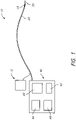
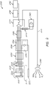
- FIG. 1 schematically illustrates an energy delivery system 10 that is configured to selectively ablate, stimulate, modulate and/or otherwise heat or treat targeted tissue (e.g., cardiac tissue, pulmonary vein, other vessels or organs, etc.).
- the system 10 can include a medical instrument 20 (i.e. catheter) comprising one or more energy delivery members 30 (e.g., radiofrequency electrodes) along a distal end of the medical instrument 20.
- the medical instrument can be sized, shaped and/or otherwise configured to be passed intraluminally (e.g., intravascularly) through a subject being treated.
- the medical instrument is not positioned intravascularly but is positioned extravascularly via laparoscopic or open surgical procedures.
- one or more temperature sensing devices or systems 60 may be included at the distal end of the medical instrument 20, or along its elongate shaft or in its handle.
- the term "distal end” does not necessarily mean the distal terminus or distal end. Distal end could mean the distal terminus or a location spaced from the distal terminus but generally at a distal end portion of the medical instrument 20.
- the medical instrument 20 is operatively coupled to one or more devices or components.
- the medical instrument 20 is coupled to a delivery module 40 (such as an energy delivery module).
- the energy delivery module 40 includes an energy generation device 42 that is configured to selectively energize and/or otherwise activate the energy delivery member(s) 30 (radiofrequency electrodes) located along the medical instrument 20.
- the energy generation device 42 comprises a radiofrequency generator.
- the energy delivery module 40 can include one or more input/output devices or components 44, such as, for example, a touchscreen device, a screen or other display, a controller (e.g., button, knob, switch, dial, etc.), keypad, mouse, joystick, trackpad, or other input device and/or the like.
- input/output devices or components 44 such as, for example, a touchscreen device, a screen or other display, a controller (e.g., button, knob, switch, dial, etc.), keypad, mouse, joystick, trackpad, or other input device and/or the like.
- the output device 44 can include a touchscreen or other display that provides tissue temperature information, contact information, other measurement information and/or other data or indicators that can be useful for regulating a particular treatment procedure.
- the energy delivery module 40 includes a processor 46 (e.g., a processing or control unit) that is configured to regulate one or more aspects of the treatment system 10.
- the module 40 can also comprise a memory unit or other storage device 48 (e.g., computer readable medium) that can be used to store operational parameters and/or other data related to the operation of the system 10.
- the processor 46 is configured to automatically regulate the delivery of energy from the energy generation device 42 to the energy delivery member 30 of the medical instrument 20 based on one or more operational schemes. For example, energy provided to the energy delivery member 30 (and thus, the amount of heat transferred to or from the targeted tissue) can be regulated based on, among other things, the detected temperature of the tissue being treated.
- the energy delivery system 10 can include one or more temperature detection devices, such as, for example, reference temperature devices (e.g., thermocouples, thermistors, etc.) and/or the like.
- the device further comprises a one or more temperature sensors or other temperature-measuring devices to help determine a peak (e.g., high or peak, low or trough, etc.) temperature of tissue being treated.
- the temperature sensors e.g., thermocouples located at, along and/or near the ablation member (e.g., RF electrode) can help with the determination of whether contact is being made between the ablation member and targeted tissue (and/or to what degree such contact is being made).
- such peak temperature is determined without the use of radiometry.
- the energy delivery system 10 comprises (or is in configured to be placed in fluid communication with) an irrigation fluid system 70.
- an irrigation fluid system 70 is at least partially separate from the energy delivery module 40 and/or other components of the system 10.
- the irrigation fluid system 70 is incorporated, at least partially, into the energy delivery module 40.
- the irrigation fluid system 70 can include one or more pumps or other fluid transfer devices that are configured to selectively move fluid through one or more lumens or other passages of the catheter 20. Such fluid can be used to selectively cool (e.g., transfer heat away from) the energy delivery member 30 during use.
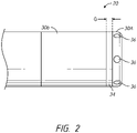
- FIG. 2 illustrates one embodiment of a distal end of a medical instrument (e.g., catheter) 20.
- the catheter 20 includes a high-resolution tip design, such that there are two adjacent electrodes or two adjacent electrode portions 30A, 30B separated by a gap G.
- the relative length of the different electrodes or electrode portions 30A, 30B can vary.
- the length of the proximal electrode 30B can be between 1 to 20 times (e.g., 1-2, 2-3, 3-4, 4-5, 5-6, 6-7, 7-8, 8-9, 9-10, 10-11, 11-12, 12-13, 13-14, 14-15, 15-16, 16-17, 17-18, 18-19, 19-20, values between the foregoing ranges, etc.) the length of the distal electrode 30A, as desired or required.
- the length of the proximal electrode 30B can be greater than 20 times (e.g., 20-25, 25-30, more than 30 times, etc.) the length of the distal electrode 30A.
- the lengths of the distal and proximal electrodes 30A, 30B are about equal.
- the distal electrode 30A is longer than the proximal electrode 30B (e.g., by 1 to 20 times, such as, for example, 1-2, 2-3, 3-4, 4-5, 5-6, 6-7, 7-8, 8-9, 9-10, 10-11, 11-12, 12-13, 13-14, 14-15, 15-16, 16-17, 17-18, 18-19, 19-20, values between the foregoing ranges, etc.).
- the distal electrode or electrode portion 30A is 0.5 mm long. In other embodiments, the distal electrode or electrode portion 30A is between 0.1 mm and 1 mm long (e.g., 0.1-0.2, 0.2-0.3, 0.3-0.4, 0.4-0.5, 0.5-0.6, 0.6-0.7, 0.-0.8, 0.8-0.9, 0.9-1 mm, values between the foregoing ranges, etc.). In other embodiments, the distal electrode or electrode portion 30A is greater than 1 mm in length, as desired or required. In some embodiments, the proximal electrode or electrode portion 30B is 2 to 4 mm long (e.g., 2-2.5, 2.5-3, 3-3.5, 3.5-4 mm, lengths between the foregoing, etc.).
- the proximal electrode portion 30B is greater than 4 mm (e.g., 4-5, 5-6, 6-7, 7-8, 8-9, 9-10 mm, greater than 10 mm, etc.) or smaller than 1 mm (e.g., 0.1-0.5 0.5-1, 1-1.5, 1.5-2 mm, lengths between the foregoing ranges, etc.), as desired or required.
- the length of the electrodes can be 1 to 5 mm (e.g., 1-2, 2-3, 3-4, 4-5 mm, lengths between the foregoing, etc.).
- the electrodes can be longer than 5 mm (e.g., 5-6, 6-7, 7-8, 8-9, 9-10, 10-15, 15-20 mm, lengths between the foregoing, lengths greater than 20 mm, etc.), as desired or required.
- the use of a high-resolution tip design can permit a user to simultaneously ablate or otherwise thermally treat targeted tissue and map (e.g., using high-resolution mapping) in a single configuration.
- such systems can advantageously permit precise high-resolution mapping (e.g., to confirm that a desired level of treatment occurred) during a procedure.
- the high-resolution tip design that includes two electrodes or electrode portions 30A, 30B can be used to record a high-resolution bipolar electrogram.
- the two electrodes or electrode portions can be connected to the inputs of an EP recorder.
- a relatively small separation distance e.g., gap G
- a medical instrument e.g., a catheter 20 can include three or more electrodes or electrode portions (e.g., separated by gaps), as desired or required. Additional details regarding such arrangements are provided below.
- the electrodes or electrode portions 30A, 30B are radiofrequency electrodes and comprise one or more metals, such as, for example, stainless steel, platinum, platinum-iridium, gold, gold-plated alloys and/or the like.
- the electrodes or electrode portions 30A, 30B are spaced apart from each other (e.g., longitudinally or axially) using a gap (e.g., an electrically insulating gap).
- a gap e.g., an electrically insulating gap.
- the length of the gap G is 0.5 mm.
- the gap G or separation distance is greater or smaller than 0.5 mm, such as, for example, 0.1-1 mm (e.g., 0.1-0.2, 0.2-0.3, 0.3-0.4, 0.4-0.5, 0.5-0.6, 0.6-0.7, 0.7-0.8, 0.8-0.9, 0.9-1.0 mm, values between the foregoing ranges, less than 0.1 mm, greater than 1 mm, etc.), as desired or required
- a separator 34 is positioned within the gap G, between the adjacent electrodes or electrode portions 30A, 30B, as depicted in FIG. 2 .
- the separator can comprise one or more electrically insulating materials, such as, for example, Teflon, polyetheretherketone (PEEK), polyetherimide resins (e.g., ULTEM TM ), ceramic materials, polyimide and the like.
- the insulating separator 34 can be 0.5 mm long. In other embodiments, the length of the separator 34 can be greater or smaller than 0.5 mm (e.g., 0.1-0.2, 0.2-0.3, 0.3-0.4, 0.4-0.5, 0.5-0.6, 0.6-0.7, 0.7-0.8, 0.8-0.9, 0.9-1.0 mm, values between the foregoing ranges, less than 0.1 mm, greater than 1 mm, etc.), as desired or required.
- 0.5 mm e.g., 0.1-0.2, 0.2-0.3, 0.3-0.4, 0.4-0.5, 0.5-0.6, 0.6-0.7, 0.7-0.8, 0.8-0.9, 0.9-1.0 mm, values between the foregoing ranges, less than 0.1 mm, greater than 1 mm, etc.
- the two electrodes or electrode portions 30A, 30B are electrically coupled to each other at the RF frequency.
- the two electrodes or electrode portions advantageously function as a single longer electrode at the RF frequency.
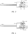
- FIGS. 3 and 4 illustrate different embodiments of catheter systems 100, 200 that incorporate a high-resolution tip design.
- the electrode radiofrequency electrode
- the high-resolution tip design 100 includes a gap G between the first and second electrodes or electrode portions 110, 114.
- the second or proximal electrode or electrode portion 114 is generally longer than the first or distal electrode or electrode portion 110.
- the length of the proximal electrode 114 can be between 1 to 20 times (e.g., 1-2, 2-3, 3-4, 4-5, 5-6, 6-7, 7-8, 8-9, 9-10, 10-11, 11-12, 12-13, 13-14, 14-15, 15-16, 16-17, 17-18, 18-19, 19-20, values between the foregoing ranges, etc.) the length of the distal electrode 110, as desired or required.
- the length of the proximal electrode can be greater than 20 times (e.g., 20-25, 25-30, more than 30 times, etc.) the length of the distal electrode.
- the lengths of the distal and proximal electrodes are about the same.
- the distal electrode 110 is longer than the proximal electrode 114 (e.g., by 1 to 20 times, such as, for example, 1-2, 2-3, 3-4, 4-5, 5-6, 6-7, 7-8, 8-9, 9-10, 10-11, 11-12, 12-13, 13-14, 14-15, 15-16, 16-17, 17-18, 18-19, 19-20, values between the foregoing ranges, etc.).
- the electrodes or electrode portions 110, 114 can be separated by a gap G.
- the gap G can comprise a relatively small electrically insulating gap or space.
- an electrically insulating separator 118 can be snugly positioned between the first and second electrodes or electrode portions 110, 114.
- the separator 118 can have a length of about 0.5 mm.
- the length of the separator 118 can be greater or smaller than 0.5 mm (e.g., 0.1-0.2, 0.2-0.3, 0.3-0.4, 0.4-0.5, 0.5-0.6, 0.6-0.7, 0.7-0.8, 0.8-0.9, 0.9-1.0 mm, values between the foregoing ranges, less than 0.1 mm, greater than 1 mm, etc.), as desired or required.
- 0.5 mm e.g., 0.1-0.2, 0.2-0.3, 0.3-0.4, 0.4-0.5, 0.5-0.6, 0.6-0.7, 0.7-0.8, 0.8-0.9, 0.9-1.0 mm, values between the foregoing ranges, less than 0.1 mm, greater than 1 mm, etc.
- the separator can include one or more electrically insulating materials (e.g., materials that have an electrical conductivity less than about 1000 or less (e.g., 500-600, 600-700, 700-800, 800-900, 900-1000, 1000-1100, 1100-1200, 1200-1300, 1300-1400, 1400-1500, values between the foregoing, less than 500, greater than 1500, etc.) than the electrical conductivity of metals or alloys).
- the separator can comprise one or more electrically insulating materials, such as, for example, Teflon, polyetheretherketone (PEEK), polyoxymethylene, acetal resins or polymers and the like.
- the separator 118 can be cylindrical in shape and can have the identical or similar diameter and configuration as the adjacent electrodes or electrode portions 110, 114.
- the outer surface formed by the electrodes or electrode portions 110, 114 and the separator 118 can be generally uniform or smooth.
- the shape, size (e.g., diameter) and/or other characteristics of the separator 118 can be different than one or more of the adjacent electrodes or electrode portions 110, 114, as desired or required for a particular application or use.
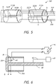
- FIG. 4 illustrates an embodiment of a system 200 having three or more electrodes or electrode portions 210, 212, 214 separated by corresponding gaps G1, G2.
- additional gaps and thus, additional electrodes or electrode portions 210, 212, 214 that are physically separated (e.g., by gaps) yet in close proximity to each other, can provide additional benefits to the high-resolution mapping capabilities of the system.
- the use of two (or more) gaps can provide more accurate high-resolution mapping data related to the tissue being treated.
- Such multiple gaps can provide information about the directionality of cardiac signal propagation.
- high-resolution mapping with high-resolution electrode portions involving multiple gaps can provide a more extended view of lesion progression during the ablation process and higher confidence that viable tissue strands are not left behind within the targeted therapeutic volume.
- high-resolution electrodes with multiple gaps can optimize the ratio of mapped tissue surface to ablated tissue surface. Preferably, such ratio is in the range of 0.2 to 0.8 (e.g., 0.2-0.3, 0.3-0.4, 0.4-.5, 0.5-0.6, 0.6-0.7, 0.7-0.8, ratios between the foregoing, etc.).
- an ablation or other treatment system can include 4 or more (e.g., 5, 6, 7, 8, more than 8, etc.) electrodes or electrode portions (and thus, 3 or more gaps, e.g., 3, 4, 5, 6, 7 gaps, more than 7 gaps, etc.), as desired or required.
- a gap and/or an electrical separator
- FIGS. 2 to 4 illustrate the embodiments illustrated in FIGS. 2 to 4 .
- an irrigation tube 120, 220 can be routed within an interior of the catheter (not shown for clarity).
- the irrigation tube 120, 220 can extend from a proximal portion of the catheter (e.g., where it can be placed in fluid communication with a fluid pump) to the distal end of the system.
- the irrigation tube 120, 220 extends and is in fluid communication with one or more fluid ports 211 that extend radially outwardly through the distal electrode 110, 210.
- the treatment system comprises an open irrigation design, wherein saline and/or other fluid is selectively delivered through the catheter (e.g., within the fluid tube 120, 220) and radially outwardly through one or more outlet ports 111, 211 of an electrode 110, 210.
- the delivery of such saline or other fluid can help remove heat away from the electrodes and/or the tissue being treated.
- such an open irrigation system can help prevent or reduce the likelihood of overheating of targeted tissue, especially along the tissue that is contacted by the electrodes.
- An open irrigation design is also incorporated in the system that is schematically illustrated in FIG. 2 .
- the distal electrode or electrode portion 34 can include a plurality of outlet ports 36 through which saline or other irrigation fluid can exit.
- a catheter can include a high-resolution-tip electrode design that includes one or more gaps in the circumferential direction (e.g., radially), either in addition to or in lieu of gaps in the longitudinal direction.
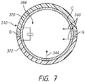
- a system 300 comprising one or more electrodes 310A, 310B is illustrated in FIG. 5 .
- the electrodes 310A, 310B can be longitudinally or axially offset from each other.
- the electrodes 310A, 310B are located along or near the distal end of a catheter.
- the electrodes 310A, 310B are located along an exterior portion of a catheter or other medical instrument.
- one or more of the electrodes can be positioned along a different portion of the catheter or other medical instrument (e.g., along at least an interior portion of a catheter), as desired or required.
- each electrode 310A, 310B comprises two or more sections 320A, 322A and/or 320B, 320B.
- the each section 320A, 322A and/or 320B, 320B can extend half-way around (e.g., 180 degrees) the diameter of the catheter.
- the circumferential extent of each section can be less than 180 degrees.
- each section can extend between 0 and 180 degrees (e.g., 15, 30, 45, 60, 75, 90, 105, 120 degrees, degrees between the foregoing, etc.) around the circumference of the catheter along which it is mounted.
- an electrode can include 2, 3, 4, 5, 6 or more circumferential sections, as desired or required.
- circumferential electrode sections are designed and oriented, electrically insulating gaps G can be provided between adjacent sections to facilitate the ability to use the electrode to conduct high-resolution mapping, in accordance with the various embodiments disclosed herein.
- two or more (e.g., 3, 4, 5, more than 5, etc.) electrodes 310A, 310B having two or more circumferential or radial sections can be included in a particular system 300, as desired or required.
- a catheter can include two or more irrigation tubes or conduits.
- one tube or other conduit can be used to deliver fluid toward or near the electrodes, while a second tube or other conduit can be used to return the fluid in the reverse direction through the catheter.
- a high-resolution tip electrode is designed to balance the current load between the various electrodes or electrode portions. For example, if a treatment system is not carefully configured, the electrical load may be delivered predominantly to one or more of the electrodes or electrode portions of the high-resolution tip system (e.g., the shorter or smaller distal electrode or electrode portion). This can lead to undesirable uneven heating of the electrode, and thus, uneven heating (e.g., ablation) of the adjacent tissue of the subject.
- one or more load balancing configurations can be used to help ensure that the heating along the various electrodes or electrode portions of the system will be generally balanced.
- the high-resolution tip design can advantageously function more like a longer, single electrode, as opposed to two or more electrodes that receive an unequal electrical load (and thus, deliver an unequal amount of heat or level of treatment to the subject's targeted tissue).
- one of the electrodes (e.g., the distal electrode) 30A can be electrically coupled to an energy delivery module 40 (i.e. a RF generator).
- the module 40 can comprise one or more components or features, such as, for example, an energy generation device that is configured to selectively energize and/or otherwise activate the energy members (e.g., RF electrodes), one or more input/output devices or components, a processor (e.g., a processing or control unit) that is configured to regulate one or more aspects of the treatment system, a memory and/or the like.
- a module can be configured to be operated manually or automatically, as desired or required.
- the distal electrode 30A is energized using one or more conductors 82 (e.g., wires, cables, etc.).
- the exterior of the irrigation tube 38 comprises and/or is otherwise coated with one or more electrically conductive materials (e.g., copper, other metal, etc.).
- the conductor 82 can be placed in contact with such a conductive surface or portion of the tube 38 to electrically couple the electrode or electrode portion 30A to an energy delivery module.
- one or more other devices and/or methods of placing the electrode or electrode portion 30A in electrical communication with an energy delivery module can be used.
- one or more wires, cables and/or other conductors can directly or indirectly couple to the electrodes, without the use of the irrigation tube.
- the first or distal electrode or electrode portion 30A is electrically coupled to the second or proximal electrode or electrode portion 30B using one more band-pass filtering elements 84.
- the band-pass filtering element 84 comprises a capacitor that electrically couples the two electrodes or electrode portions 30A, 30B when radiofrequency current is applied to the system.
- the capacitor 84 comprises a 100 nF capacitor that introduces a series impedance lower than about 3 ⁇ at 500 kHz, which, according to some arrangements, is a target frequency for RF ablation.
- the capacitance of the capacitor(s) or other band-pass filtering elements 84 that are incorporated into the system can be greater or less than 100 nF, for example, 5 nF to 300 nF, according to the operating RF frequency, as desired or required.
- the capacitance of the filtering element 84 is selected based on a target impedance at a particular frequency or frequency range.
- the system can be operated at a frequency of 200 kHz to 10 MHz (e.g., 200-300, 300-400, 400-500, 500-600, 600-700, 700-800, 800-900, 900-1000 kHz, up to 10 MHz or higher frequencies between the foregoing ranges, etc.).
- the capacitor that couples adjacent electrodes or electrode portions to each other can be selected based on the target impedance for a particular frequency. For example, a 100 nF capacitor provides about 3 ⁇ of coupling impedance at an operating ablation frequency of 500 kHz.
- a series impedance of 3 ⁇ across the electrodes or electrode portions 30A, 30B is sufficiently low when compared to the impedance of the conductor 82 (e.g., wire, cable, etc.), which can be about 5-10 ⁇ , and the impedance of tissue, which can be about 100 ⁇ , such that the resulting tissue heating profile is not negatively impacted when the system is in use.
- a filtering element is selected so that the series impedance across the electrodes or electrode portions is lower than the impedance of the conductor that supplies RF energy to the electrodes.
- the insertion impedance of the filtering element is 50% of the conductor 82 impedance, or lower, or 10% of the equivalent tissue impedance, or lower.
- a filtering element e.g., capacitor a filter circuit such as the one described herein
- the filtering element can be located at a variety of locations of the device or accompanying system.
- the filtering element is located on or within a catheter (e.g., near the distal end of the catheter, adjacent the electrode, etc.).
- the filtering element is separate of the catheter.
- the filtering element can be positioned within or along a handle to which the catheter is secured, within the generator or other energy delivery module, within a separate processor or other computing device or component and/or the like).
- a filtering element 384 can be included in an electrode 310 comprising circumferentially-arranged portions 320, 322.
- the filtering element 384 permits the entire electrode 310 to be energized within RF frequency range (e.g., when the electrode is activated to ablate).
- One or more RF wires or other conductors 344 can be used to deliver power to the electrode from a generator or source.
- separate conductors 340 can be used to electrically couple the electrode 310 for mapping purposes.
- the filtering element can include something other than a capacitor.
- the filtering element comprises a LC circuit (e.g., a resonant circuit, a tank circuit, a tuned circuit, etc.).
- LC circuit e.g., a resonant circuit, a tank circuit, a tuned circuit, etc.
- the relatively small gap G between the adjacent electrodes or electrode portions 30A, 30B can be used to facilitate high-resolution mapping of the targeted tissue.
- the separate electrodes or electrode portions 30A, 30B can be used to generate an electrogram that accurately reflects the localized electrical potential of the tissue being treated.
- a physician or other practitioner using the treatment system can more accurately detect the impact of the energy delivery to the targeted tissue before, during and/or after a procedure.
- the more accurate electrogram data that result from such configurations can enable the physician to detect any gaps or portions of the targeted anatomical region that was not properly ablated or otherwise treated.
- a high-resolution tip design can enable a cardiac electrophysiologist to more accurately evaluate the morphology of resulting electrograms, their amplitude and width and/or to determine pacing thresholds.
- morphology, amplitude and pacing threshold are accepted and reliable EP markers that provide useful information about the outcome of an ablation or other heat treatment procedure.
- the high-resolution-tip electrode embodiments disclosed herein are configured to provide localized high-resolution electrogram.
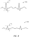
- the electrogram that is obtained using a high-resolution-tip electrode in accordance with embodiments disclosed herein, can provide electrogram data (e.g., graphical output) 400a, 400b as illustrated in FIG. 8 .
- the localized electrograms 400a, 400b generated using the high-resolution-tip electrode embodiments disclosed herein include an amplitude A1, A2.
- the amplitude of the electrograms 400a, 400b obtained using high-resolution-tip electrode systems can be used to determine whether targeted tissue adjacent the high-resolution-tip electrode has been adequately ablated or otherwise treated.
- the amplitude A1 of an electrogram 400a in untreated tissue e.g., tissue that has not been ablated or otherwise heated
- the amplitude of the electrogram can be measured to determine whether tissue has been treated.
- the electrogram amplitude A1 of untreated tissue in a subject can be recorded and used as a baseline. Future electrogram amplitude measurements can be obtained and compared against such a baseline amplitude in an effort to determine whether tissue has been ablated or otherwise treated to an adequate or desired degree.
- a comparison is made between such a baseline amplitude (A1) relative to an electrogram amplitude (A2) at a tissue location being tested or evaluated.
- a ratio of A1 to A2 can be used to provide a quantitative measure for assessing the likelihood that ablation has been completed. In some arrangements, if the ratio (i.e., A1/A2) is above a certain minimum threshold, then the user can be informed that the tissue where the A2 amplitude was obtained has been properly ablated.
- adequate ablation or treatment can be confirmed when the A1/A2 ratio is greater than 1.5 (e.g., 1.5-1.6, 1.6-1.7, 1.7-1.8, 1.8-1.9, 1.9-2.0, 2.0-2.5, 2.5-3.0, values between the foregoing, greater than 3, etc.).
- confirmation of ablation can be obtained when the ratio of A1/A2 is less than 1.5 (e.g., 1-1.1, 1.1-1.2, 1.2-1.3, 1.3-1.4, 1.4-1.5, values between the foregoing, etc.).
- the ablation system comprises a pacemaker that is configured to selectively pace or increase the heart rate of a subject.
- pacing can be used to confirm whether targeted tissue (e.g., cardiac tissue) has been properly ablated.
- targeted tissue e.g., cardiac tissue
- a system and related method can provide the user with information for assessing the success of a treatment procedure. For example, data provided by the system can be used to determine if the targeted tissue has been properly ablated.
- the various systems, devices and methods disclosed herein can be used to ensure that a desired or required level of treatment to targeted tissue has been accomplished.
- the confirmation and other feedback provided by the various systems, devices and methods disclosed herein can be used in addition to or in lieu of any other protocols for confirming successful treatment of targeted tissue.
- An energy delivery module i.e. a radiofrequency generator of an ablation system comprises a pacemaker device or system.
- the pacemaker device or system is integrated within the energy delivery module.
- Such a pacemaker device or system can be configured to selectively pace cardiac tissue or increase a heart rate of a subject being treated. According to some embodiments, such pacing or an increase in heart rate is performed for purposes of confirming successful ablation of targeted tissue (e.g., atrial, ventricular and/or other cardiac tissue), as discussed in greater detail herein. However, the use of pacing can be performed for one or more other purposes as well, either in addition to or in lieu of confirmation of ablation, as desired or required.
- targeted tissue e.g., atrial, ventricular and/or other cardiac tissue
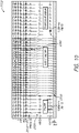
- a system 2000 comprises an energy delivery module (i.e. a radiofrequency generator) 2240 that is configured to couple to a catheter 2220.
- the catheter 2220 comprises one or more high-resolution electrodes or electrode portions 2222, 2224 located along the distal end of the catheter or other medical instrument 2220.
- the high-resolution electrodes or electrode portions 2222, 2224 are electrically coupled to each other using one or more filtering elements that permit the electrodes or electrode portions 2222, 2224 to selectively deliver ablative (e.g., radiofrequency) energy to targeted tissue of a subject while permitting the electrodes or electrode portions to obtain high-resolution mapping data of adjacent tissue (e.g., when ablative energy is not being provided to the electrodes or electrode portions), as discussed herein.
- the filtering element positioned between the electrodes or electrode portions 2222, 2224 in FIG. 9 comprises a capacitor.
- the system 2000 can further comprise a catheter cable 2250 that is used to physically and/or operatively couple the catheter or other medical instrument 2220 to the energy delivery module (e.g., RF generator) 2240.
- the energy delivery module e.g., RF generator
- a cable or other connector 2250 can be physically incorporated into the design of the catheter or other medical instrument 2220.
- the catheter cable 2250 can be separate and distinct from the catheter or other medical instrument 2220, as desired or required.
- the energy delivery module (e.g., a RF generator) can be configured to couple to a pacemaker device or system 2400.
- a pacemaker device or system is incorporated into the energy delivery module 2240.
- the RF generator or any other energy delivery module 2240 can include one or more ports and/or other couplings that are configured to receive, either directly or indirectly, a connection from a pacemaker device or system 2400 (e.g., an off-the-shelf or other third-party pacemaker device or system).
- a pacemaker device or system 2400 e.g., an off-the-shelf or other third-party pacemaker device or system.
- a pacemaker device or system 2400 is configured to indirectly couple to the energy delivery module 2240, as the pacemaker device or system 2400 connects or otherwise attaches or couples, via a pacemaker cable 2410, to a different component or device of the system 2000 (e.g., an EP recording system 2310, such as, a recording system provided by a third party, a recorder cable 2300 that operatively couples to the energy delivery module and/or EP recorder, etc.).
- an energy delivery module e.g., a RF generator
- Any ports and/or other connection sites included in the RF generator (or other energy delivery module) 2240 and/or any other component of the system 2000 that is configured to receive a pacemaker cable 2410 or other connection from a pacemaker device or system 2400 can be standard or non-standard.
- a pacemaker device or system 2400 can be used to provide a pacing current to the catheter or other medical instrument 2220 in order to selectively increase the heart rate of the subject's heart.
- the heart rate of a subject is increased from a baseline heart rate to 100-200 beats per minute, bpm, (e.g., 100-105, 105-110, 110-115, 115-120, 120-125, 125-130, 130-135, 135-140, 140-145, 145-150, 150-160, 160-170, 170-180, 180-190, 190-200 bpm, 120-150 bpm, frequencies between the foregoing, etc.) by delivering a pacing signal to the catheter.
- bpm e.g., 100-105, 105-110, 110-115, 115-120, 120-125, 125-130, 130-135, 135-140, 140-145, 145-150, 150-160, 160-170, 170-180, 180-190, 190-200
- the pacing current generated by the pacemaker device or system 2400 is directed to and routed, at least partially, through the energy delivery module (e.g., RF generator) 2240.
- the energy delivery module 2240 comprises a filter section 2246 through which the pacing current passes.
- the filter section 2246 of the energy delivery module 2240 comprises low insertion impedance EGM filters that facilitate the delivery of the pacing current to the catheter or other medical instrument 2220 coupled to the energy delivery module 2240.
- Such filters can permit the system 2000 to deliver energy (e.g., radiofrequency energy, other ablative energy, etc.) to the electrode(s) of the catheter 2220 while simultaneously providing a desired pacing current to such electrode(s).
- the energy delivery module (e.g., RF generator) 2240 can further include an energy delivery portion 2244. Accordingly, RF and/or other energy generated by the energy delivery module 2240 can be delivered to a catheter or other medical instrument 2220 to ablate or otherwise provide heat treatment to targeted tissue of a subject P.
- the catheter or other medical instrument 2220 is coupled to the energy delivery module (e.g., RF generator) 2240 using a catheter cable 2250.
- the catheter 2220 that operatively couples to the energy delivery module 2240 includes a high-resolution electrode design.
- the catheter comprises an electrode that is configured to obtain high-resolution mapping data (e.g., when ablative energy is not being delivered to the electrode), in accordance with the various embodiments disclosed herein, or variations thereof.
- a filtering element or other feature can advantageously permit the electrode along the distal end of the catheter 2220 to obtain high resolution mapping data before and/or after ablative energy (e.g., radiofrequency energy) has been delivered to the catheter 2220.
- the design of such a high-resolution electrode assembly can permit a user to obtain and use accurate mapping data associated with the specific location of the electrode.
- the catheter 2220 of the system 2000 comprises a high-resolution electrode assembly (e.g., first and second electrodes or electrode portions 2222, 2224 located along the distal end of the catheter).
- the catheter or other medical instrument 2220 can comprise one or more (e.g., 2, 3, more than 3, etc.) additional mapping electrodes (e.g., standard ring electrodes) located along or near the high-resolution electrodes or electrode portions.
- a catheter 2220 can include two ring electrodes 2228 that are located proximal to the high-resolution electrode(s) or electrode portion(s) and that are configured to obtain mapping data from surrounding tissue of the subject.
- any of the cardiac pacing concepts disclosed herein e.g., the ability to provide pacing currents to a catheter or other medical instrument, the ability to pace or increase the heart rate of a subject prior to or during a cardiac treatment procedure, etc.
- catheters or other medical instruments that do not include high-resolution mapping electrodes or related features.
- the pacing concepts e.g., and the related confirmation of ablation of targeted tissue
- pacing currents can be provided to the electrode or other energy delivery device of a catheter (or other medical instrument).
- the pacing current that is provided to the electrode or other energy delivery device is greater than the pre-ablation pacing threshold level, but lower than the post-ablation pacing threshold level.
- the subject's heart will be paced (e.g., the subject's heart rate will increase to an elevated heart rate frequency or level).
- the pacemaker signal can increase the subject's heart rate to 100-150 beats per minute (bpm), e.g., 100-105, 105-110, 110-115, 115-120, 120-125, 125-130, 130-135, 135-140, 140-145, 145-150 bpm, value between the foregoing ranges, etc.).
- the pacing can increase a subject's heart rate to levels exceeding 150 bpm (e.g., 150-160, 160-170, 170-180 bpm, values between the foregoing ranges, values greater than 180 bpm, etc.) as desired to required.
- the pacing current provided by the pacemaker device or system 2400 integrated with the energy delivery module (i.e. the RF generator) 2240 will exceed a pre-ablation pacing threshold.
- the pacing current will be configured to stimulate the subject's heart to a desired elevated rate or level and will also be configured to surpass the pacing threshold at which the targeted tissue of the subject will be ablated or otherwise heat-treated to a desired level.
- the pacing current provided by the pacemaker device or system 2400 is greater than 15 milliamps (mA).
- the pacing current provided by the pacemaker device or system is 15-20 milliamps (mA), e.g., 15-16, 16-17, 17-18, 18-19, 19-20 mA, currents between the foregoing ranges, etc.
- the pacing current provided by the pacemaker device or system is less than 15 mA (e.g., 10-11, 11-12, 12-13, 13-14, 14-15 mA, currents between the foregoing ranges, etc.) or greater than 20 mA, (e.g., 20-21, 21-22, 22-23, 23-24, 24-25, 25-30 mA, currents between the foregoing ranges, currents greater than 30 mA, etc.), as desired or required.
- the pacing current provided by the pacemaker device or system is 5 to 20 mA (e.g., 10-15 mA).
- the heart rate of the subject being treated will increase above the subject's baseline (e.g., normal) heart rate.
- the formation of a lesion or the completion of heat treatment of the targeted tissue will cause the pacing threshold to increase considerably, from pre-ablation levels (e.g. 1 to 5 mA) to post-ablation levels (e.g. 15 to 20 mA, or greater).
- pre-ablation levels e.g. 1 to 5 mA
- post-ablation levels e.g. 15 to 20 mA, or greater.
- the pre-ablation pacing threshold is approximately 1 mA and the post-ablation pacing threshold is approximately 20 mA.
- pacing currents of 10 mA would produce "heart capture,” meaning an increase of the heart rate to the rate programmed on pacemaker device or system 2400.
- the post-ablation pacing threshold exceeds the pacing current amplitude (e.g., in the specific, non-limiting example provided above, 20 mA is greater than 10 mA).
- the heart rate of the subject being treated will drop to a level below the elevated heart rate induced by the pacing signal generated by the pacemaker device or system.
- the loss of such an elevated pacing rate of cardiac tissue is referred to as "loss of capture," providing another form of confirmation to a user that the targeted tissue has been properly treated (e.g., ablated).
- such confirmation of adequate ablation of tissue can help prevent overheating of targeted tissue, as the user is notified in a prompt manner that loss of capture (e.g., or a desired level of tissue ablation) has been attained. As a result, the likelihood of charring or overheating of targeted tissue can be prevented. This can help ensure that undesirable damage to the targeted tissue is avoided and/or that damage to tissue surrounding or adjacent to the targeted tissue is not inadvertently harmed.
- loss of capture e.g., or a desired level of tissue ablation
- high-resolution electrode(s) or electrode portion(s) further enhances the pacing data obtained by the system, in accordance with several embodiments.
- the ability of high-resolution electrode(s) or electrode portion(s), in accordance with the various configurations described herein or variations thereof to pace the cardiac tissue located in its immediate vicinity ensures that the devices, systems, methods and techniques disclosed herein have high specificity.
- pacing of far-field tissues is avoided. Therefore, the technique advantageously monitors the localized effects of cardiac ablation.
- the cardiac data obtained using the system are specific to the anatomical region adjacent the high-resolution electrode, providing a more accurate representation of the condition of the targeted tissue.
- the likelihood of overheating targeted tissue is advantageously reduced.
- the pre-ablation pacing threshold is greater than 1 or 2 milliamps (mA).
- the pre-ablation pacing threshold is 1 -3 mA (e.g., 1-1.5, 1.5-2, 2-2.5, 2.5-3 mA, values between the foregoing ranges, etc.).
- the pre-ablation pacing threshold is less than 1 mA (e.g., 0.1-0.2, 0.2-0.3, 0.3-0.4, 0.4-0.5, 0.5-0.6, 0.6-0.7, 0.7-0.8, 0.8-0.9, 0.9-1 mA, values between the foregoing ranges, but not values less than 0.1 mA, etc.), as desired or required.
- the pre-ablation pacing threshold is 0.1 to 3 mA (e.g., 0.5-2 mA).
- the post-ablation pacing threshold is greater than 10 milliamps (mA).
- the post-ablation pacing threshold is 10-15 mA (e.g., 10-11, 11-12, 12-13, 13-14, 14-15 mA, values between the foregoing ranges, values greater than 15 mA, etc.).
- the post-ablation pacing threshold is less than 10 mA (e.g., 5-6, 6-7, 7-8, 8-9, 9-10 mA, values between the foregoing ranges, less than 5 mA, etc.), as desired or required.
- the system 2000 is configured to terminate the delivery of RF (or other energy) from the energy delivery module 2240 (e.g., RF generator) to the catheter 2220, either immediately or following a particular time period
- the energy delivery module 2240 e.g., RF generator
- a processor unit of the energy delivery module is configured to automatically terminate the delivery of RF energy to the catheter once loss of capture has been attained.
- the processor can be configured to automatically terminate (or alter) a delivery of energy (e.g., RF) to the catheter or other medical instrument after a certain time period after loss of capture has been attained.
- a delivery of energy e.g., RF
- the processor or other control unit of the energy delivery module e.g., RF generator
- any other processor or control unit operatively coupled to the system 2000 can be configured to permit the delivery of energy to the electrode(s) or other energy delivery member of the catheter or other medical instrument for 0.5-5 seconds (e.g., 0.5-1, 1-1.5, 1.5-2, 2-2.5, 2.5-3, 3-3.5, 3.5-4, 4-4.5, 4.5-5 seconds, time periods between the foregoing ranges, etc.) after loss of capture has been achieved.
- 0.5-5 seconds e.g., 0.5-1, 1-1.5, 1.5-2, 2-2.5, 2.5-3, 3-3.5, 3.5-4, 4-4.5, 4.5-5 seconds, time periods between the foregoing ranges, etc.
- the delivery of energy can continue for a time period greater than 5 seconds after loss of capture (e.g., 5-6, 6-7, 7-8, 8-9, 9-10, 10-15, 15-20, 20-30 seconds, time periods between the foregoing ranges, greater than 30 seconds, etc.).
- a protocol or configuration can help ensure that proper ablation has been accomplished.
- the confirmation of completed ablation using the pacing of cardiac tissue and the subsequent loss of capture can be used either in lieu of or in addition to other metrics, techniques, tools and/or methods, such as, for example, ECG amplitude reductions, visual evidence of lesion formation (e.g., fluoro and/or ultrasound imaging, other imaging, etc.) and/or the like, regardless of whether such confirmation tools are specifically disclosed herein.
- the confirmation procedures relating to pacing and loss of capture are used as the sole or primary method of confirming proper ablation of targeted tissue.
- the use of such techniques and methods can be used to confirm or otherwise validate results and data obtained using one or more other techniques or methods, as desired or required.
- the system 2000 can additionally include (or be operatively coupled with) an EP recording system 2310 through which various mapping and other signals (e.g., ECG signals) are received and/or processed.
- one or more output devices 2340, 2342 e.g., displays, other screens, etc.
- displays, other screens, etc. can be provided to visually display data and/or other information relevant to a procedure being conducted by the system 2000.
- the displays and/or other output devices 2340, 2342 can be configured to receive pacing or heart rate data obtained using the high-resolution electrode(s) or electrode portion(s), ECG data (e.g., obtained from high-resolution electrodes or electrode portions), tissue contact data, imaging data and graphical representations and/or the like.
- the system 2000 can include one or more of the following: a return electrode 2250 (e.g. positioned along the lower portion of a subject P), an ECG cable that operatively couples the system 2000 to surface and/or other ECG electrodes (e.g., to provide ECG data before, during and/or after a procedure) and/or the like.
- FIG. 10 illustrates one embodiment of a graphical data output 2500 (e.g., as provided by the system to a display or other output device).
- the graphical output 2500 comprises various charts indicative of one or more data sets obtained by an ablation system before, during and after the execution of an ablation procedure.
- graphs 2510 are provided regarding ECG data that are obtained by the electrodes of the catheter.
- the output 2500 comprises a graphical representation 2530 of the heart rate.
- a pacing signal is provided by the system to increase the heart rate of the subject being treated. This is visible in the embodiment of FIG.
- the post-ablation pacing threshold will exceed the amplitude of the pacing current, as a confirmation that ablating the targeted tissue was successful in rendering such tissue non-viable. Accordingly, the measured heart rate will drop, providing graphical confirmation 2340 of loss of capture to a user. As noted herein, once loss of capture has been confirmed, the user manually (and/or the system, e.g., automatically) can terminate an ablation procedure, either immediately or following a desired period, in accordance with a particular protocol or treatment technique.
- the high-resolution-tip electrode systems that are used to create a more complete and comprehensive map of targeted tissue
- additional information regarding the position of the roving catheter can be obtained and provided to the user during a procedure.
- information can be obtained regarding the nature, type and other details regarding the tissue that is adjacent the electrode.
- the high-resolution-tip embodiments disclosed herein can help determine whether a specific tissue region has been adequately ablated (e.g., see the disclosure above with reference to FIG. 8 ).
- any of the high-resolution-tip electrode devices or systems disclosed herein can be used as stand-alone mapping systems to accurately assess the condition of a subject's targeted anatomical region, even with the use of a separate mapping system.
- a user can move a high-resolution-tip electrode catheter or other medical instrument to various locations within a subject's anatomy to generate a detailed, accurate and complete electrical map, as desired or required.
- the ability to use a single device to both map and ablate tissue permits a user to more expeditiously perform an overall assessment and treatment of a subject.
- the ability to create a more comprehensive map of the subject's tissue allows a user to perform a subject treatment procedure with greater accuracy and precision. As discussed, this can help reduce the overall (and sometimes unnecessary) trauma to the subject, improve recovery and provide for better and effective treatment of the subject's disease.
- the ability of the user to determine whether tissue has already been ablated or otherwise treated to a sufficient level can further improve the efficacy, efficiency and/or safety of a procedure.
- the system comprises various features that are present as single features (as opposed to multiple features).
- the system includes a single catheter that is configured to obtain high-resolution mapping of tissue.
- the system can include a single energy delivery module (e.g., a generator) for supplying ablative or other energy to the catheter.
- the system can further include a single processor that is configured to regulate the delivery of energy from the energy delivery module to the catheter.
- the catheter can include a split-tip electrode design and/or any other high-resolution configuration.
- the system can include a single pacemaker that is integrated with the energy delivery module to selectively pace or increase the heartrate of a subject's heart.
- the system consists essentially of a catheter that is configured to obtain high-resolution mapping of tissue, an energy delivery module (i.e. a RF generator) for supplying ablative or other energy to the catheter, and a processor that is configured to regulate the delivery of energy from the energy delivery module to the catheter.
- the system consists essentially of a catheter that is configured to obtain high-resolution mapping of tissue, an energy delivery module (e.g., a RF or other generator) for supplying ablative or other energy to the catheter, a processor that is configured to regulate the delivery of energy from the energy delivery module to the catheter and a pacemaker for selectively pacing the heart of the subject being treated.
- Any methods described herein do not form part of the claimed subject-matter and may be embodied in, and partially or fully automated via, software code modules executed by one or more processors or other computing devices. The methods may be executed on the computing devices in response to execution of software instructions or other executable code read from a tangible computer readable medium.
- a tangible computer readable medium is a data storage device that can store data that is readable by a computer system. Examples of computer readable mediums include read-only memory, random-access memory, other volatile or non-volatile memory devices, CD-ROMs, magnetic tape, flash drives, and optical data storage devices.
- methods may be implemented as computer-executable instructions stored in one or more tangible computer storage media.
- such computer-executable instructions stored in tangible computer storage media define specific functions to be performed by computer hardware such as computer processors.
- the computer-executable instructions are loaded into memory accessible by at least one computer processor.
- the at least one computer processor then executes the instructions, causing computer hardware to perform the specific functions defined by the computer-executable instructions.
- computer execution of computer-executable instructions is equivalent to the performance of the same functions by electronic hardware that includes hardware circuits that are hardwired to perform the specific functions.
- embodiments illustrated herein are typically implemented as some combination of computer hardware and computer-executable instructions, the embodiments illustrated herein could also be implemented as one or more electronic circuits hardwired to perform the specific functions illustrated herein.
- the various systems, devices and/or related methods disclosed herein can be used to at least partially ablate and/or otherwise ablate, heat or otherwise thermally treat one or more portions of a subject's anatomy, including without limitation, cardiac tissue (e.g., myocardium, atrial tissue, ventricular tissue, valves, etc.), a bodily lumen (e.g., vein, artery, airway, esophagus or other digestive tract lumen, urethra and/or other urinary tract vessels or lumens, other lumens, etc.), sphincters, other organs, tumors and/or other growths, nerve tissue and/or any other portion of the anatomy.
- cardiac tissue e.g., myocardium, atrial tissue, ventricular tissue, valves, etc.
- a bodily lumen e.g., vein, artery, airway, esophagus or other digestive tract lumen, urethra and/or other urinary tract vessels or lumens, other lumens,
- the selective ablation and/or other heating of such anatomical locations can be used to treat one or more diseases or conditions, including, for example, atrial fibrillation, mitral valve regurgitation, other cardiac diseases, asthma, chronic obstructive pulmonary disease (COPD), other pulmonary or respiratory diseases, including benign or cancerous lung nodules, hypertension, heart failure, denervation, renal failure, obesity, diabetes, gastroesophageal reflux disease (GERD), other gastroenterological disorders, other nerve-related disease, tumors or other growths, pain and/or any other disease, condition or ailment.
- diseases or conditions including, for example, atrial fibrillation, mitral valve regurgitation, other cardiac diseases, asthma, chronic obstructive pulmonary disease (COPD), other pulmonary or respiratory diseases, including benign or cancerous lung nodules, hypertension, heart failure, denervation, renal failure, obesity, diabetes, gastroesophageal reflux disease (GERD), other gastroenterological disorders, other nerve-related disease, tumors or other growths
Description
- The invention relates to a system for delivering energy to targeted cardiac tissue of a subject and for confirming successful ablation of said targeted cardiac tissue.
- Tissue ablation may be used to treat a variety of clinical disorders. For example, tissue ablation may be used to treat cardiac arrhythmias by at least partially destroying (e.g., at least partially or completely ablating, interrupting, inhibiting, terminating conduction of, otherwise affecting, etc.) aberrant pathways that would otherwise conduct abnormal electrical signals to the heart muscle. Several ablation techniques have been developed, including cryoablation, microwave ablation, radio frequency (RF) ablation, and high frequency ultrasound ablation. For cardiac applications, such techniques are typically performed by a clinician who introduces a catheter having an ablative tip to the endocardium via the venous vasculature, positions the ablative tip adjacent to what the clinician believes to be an appropriate region of the endocardium based on tactile feedback, mapping electrocardiogram (ECG) signals, anatomy, and/or fluoroscopic imaging, actuates flow of an irrigant to cool the surface of the selected region, and then actuates the ablative tip for a period of time and at a power believed sufficient to destroy tissue in the selected region.
- For example,
U.S. Publ. No. 2007/0198007 discloses methods and systems for the treatment of conduction disturbances of the heart.U.S. Publ. No. 2009/0306641 discloses therapies for validating and monitoring percutaneous cardiac ablation procedures. - Successful electrophysiology procedures require precise knowledge about the anatomic substrate. Additionally, ablation procedures may be evaluated within a short period of time after their completion. Cardiac ablation catheters typically carry only regular mapping electrodes. Cardiac ablation catheters may incorporate high-resolution mapping electrodes. Such high-resolution mapping electrodes provide more accurate and more detailed information about the anatomic substrate and about the outcome of ablation procedures. High-resolution mapping electrodes can allow the electrophysiology to evaluate precisely the morphology of electrograms, their amplitude and width and to determine changes in pacing thresholds. Morphology, amplitude and pacing threshold are accepted and reliable electrophysiology (EP) markers that provide useful information about the outcome of ablation.
- The present invention provides a system for delivering energy to targeted cardiac tissue of a subject and for confirming successful ablation of said targeted cardiac tissue, comprising:
- a catheter comprising a high resolution electrode along a distal end of the catheter configured to deliver ablative or other energy to tissue and capable of transferring heat to or from such tissue, while being capable of obtaining accurate mapping data of adjacent tissue;
- an energy delivery module comprising a processor, the energy delivery module being configured to operatively couple to the catheter, wherein the energy delivery module is configured to energize the electrode to selectively ablate targeted cardiac tissue adjacent the electrode; wherein the energy delivery module comprises a radiofrequency (RF) generator configured to deliver RF energy to the electrode; and
- a pacemaker, wherein the pacemaker is integral to the energy delivery module;
- wherein the system is configured to detect a signal relating to a localized heart rate at the high resolution electrode via the high resolution electrode;
- wherein the energy delivery module is configured to selectively pace cardiac tissue in order to attain capture of the heart of the subject;
- wherein the system is configured, via a predetermined pacing signal provided to the catheter by the pacemaker, to increase the heart rate of the subject from a baseline level to an elevated level, the predetermined pacing signal comprising a pacing level greater than a pre-ablation pacing threshold level of 0.1 to 3 milliamps;
- wherein the processor is configured to terminate the delivery of energy to the electrode after loss of capture of the heart of the subject;
- wherein the high resolution electrode comprises a distal portion and a proximal portion, the distal and proximal portions of the high resolution electrode being operatively coupled to each other using at least one filtering element, wherein the filtering element comprises a capacitor, wherein the distal and proximal portions of the electrode function as a single longer electrode in a RF operating range;
- wherein the pacing level of predetermined pacing signal is 5 to 20 milliamps (mA);
- wherein the elevated level of the heart rate upon pacing the cardiac tissue at the predetermined pacing level is 100 to 200 beats per minute (bpm); and
- wherein the energy delivery module comprises at least one filter, the at least one filter being configured to isolate the signal relating to the localized heart rate signal.
- In an embodiment of the invention, the catheter further comprises at least one additional mapping electrode.
- In an embodiment of the invention, the pre-ablation pacing threshold level is 0.5 to 2 milliamps (mA).
- In an embodiment of the invention, the processor is configured to terminate the delivery of energy to the electrode as soon as the heart rate drops below the elevated level or after loss of capture of the heart of the subject.
- In an embodiment of the invention, the processor is configured to terminate the delivery of energy to the electrode following a pre-determined time period after the heart rate drops below the elevated level or after loss of capture of the heart of the subject.
- In an embodiment of the invention, the predetermined time period is 0.5 to 10 seconds.
- In an embodiment of the invention, the system further comprises at least one output configured to receive data related to the subject's heart rate.
- In an embodiment of the invention, the at least one output comprises a display.
- In an embodiment of the invention, the system further comprises an EP recording system configured to provide and process data related to the subject's heart rate.
- Described herein is a system for delivering energy to targeted cardiac tissue of a subject and for confirming successful ablation of said targeted cardiac tissue comprises a medical instrument (e.g., catheter) comprising a high-resolution (e.g., split-tip) electrode along a distal end of the catheter, an energy delivery module comprising a processor, the energy delivery module being configured to operatively couple to the catheter, wherein the energy delivery module is configured to energize the electrode to selectively ablate targeted cardiac tissue adjacent the electrode, wherein the energy delivery module is configured to couple to a pacemaker for selectively pacing cardiac tissue in order to attain capture of the heart of the subject, wherein the system is configured, via a predetermined pacing signal provided to the catheter by the pacemaker, to increase the heart rate of the subject from a baseline level to an elevated level, the predetermined pacing signal comprising a pacing level greater than a pre-ablation pacing threshold level, and wherein the processor is configured to terminate the delivery of energy to the electrode after loss of capture of the heart of the subject.
- The pacemaker is included in the system, the pacemaker is integral to the energy delivery module. The energy delivery module is configured to deliver radiofrequency (RF) energy to the electrode, wherein the energy delivery module comprises a radiofrequency (RF) generator, wherein the high-resolution electrode comprises a distal portion and a proximal portion, the distal and proximal portions of the high-resolution electrode being operatively coupled to each other using at least one filtering element, wherein the filtering element comprises a capacitor, wherein the pacing level of predetermined pacing signal is 5 to 20 milliamps (mA), wherein the elevated level of the heart rate upon pacing the cardiac tissue at the predetermined pacing level is 100 to 200 beats per minute (bpm), and wherein the energy delivery module comprises at least one filter, the at least one filter being configured to isolate a signal relating to the localized heart rate signal measured using the high-resolution mapping electrode.
- The pacemaker is included in the system, wherein the high-resolution electrode comprises a distal portion and a proximal portion, the distal and proximal portions of the high-resolution electrode being operatively coupled to each other using at least one filtering element, wherein the filtering element comprises a capacitor, wherein the pacing level of predetermined pacing signal is 5 to 20 milliamps (mA), and wherein the elevated level of the heart rate upon pacing the cardiac tissue at the predetermined pacing level is 100 to 200 beats per minute (bpm).
- The pacemaker is integral to the energy delivery module. The energy delivery module is configured to deliver radiofrequency (RF) energy to the electrode. The high-resolution electrode comprises a distal portion and a proximal portion, the distal and proximal portions of the high-resolution electrode being operatively coupled to each other using at least one filtering element. The at least one filtering element comprises a capacitor.
- According to some embodiments, the catheter further comprises at least one additional mapping electrode. The energy delivery module comprises a radiofrequency (RF) generator. The energy delivery module comprises at least one filter, the at least one filter being configured to isolate a signal relating to the localized heart rate signal measured using the high-resolution mapping electrode. In some embodiments, the pacing level of predetermined pacing signal is 5 to 20 milliamps (mA) (e.g., 5-6, 6-7, 7-8, 8-9, 9-10, 10-11, 11-12, 12-13, 13-14, 14-15, 15-16, 16-17, 17-18, 18-19, 19-20 mA, etc.). In some embodiments, the pacing level of predetermined pacing signal is 10 to 15 milliamps (mA).
- The elevated level of the heart rate upon pacing the cardiac tissue at the predetermined pacing level is 100 to 200 beats per minute (bpm) (e.g., e.g., 100-105, 105-110, 110-115, 115-120, 120-125, 125-130, 130-135, 135-140, 140-145, 145-150, 150-155, 155-160, 160-165, 165-170, 170-175, 175-180, 180-185, 185-190, 190-195, 195-200 bpm, etc.). In some embodiments, the elevated level of the heart rate upon pacing the cardiac tissue at the predetermined pacing level is 120 to 150 beats per minute (bpm). The pre-ablation pacing threshold level is 0.1 to 3 milliamps (mA) (e.g., 0.1-0.2, 0.2-0.3, 0.3-0.4, 0.4-0.5, 0.5-0.6, 0.6-0.7, 0.7-0.8, 0.8-0.9, 0.9-1.0, 1.0-1.1, 1.1-1.2, 1.2-1.3, 1.3-1.4, 1.4-1.5, 1.5-1.6. 1.6-1.7, 1.7-1.8, 1.8-1.9, 1.9-2, 2-2.5, 2.5-3 mA, etc.). In some embodiments, the pre-ablation pacing threshold level is 0.5 to 2 milliamps (mA).
- The processor is configured to terminate the delivery of energy to the electrode after loss of capture of the heart of the subject. In some embodiments, the processor is configured to terminate the delivery of energy to the electrode following a pre-determined time period after loss of capture of the heart of the subject. In some embodiments, the predetermined time period comprises 0.5 to 10 seconds (e.g., 0.5-1, 1-2, 2-3, 3-4, 4-5, 5-6, 6-7, 7-8, 8-9, 9-10 seconds, values between the foregoing ranges, etc.). In some embodiments, the predetermined time period comprises 1 to 5 seconds.
- In some embodiments, the system further includes at least one output configured to receive data related to the subject's heart rate. In some embodiments, the at least one output comprises a display (e.g., a monitor or other display, etc.). In some embodiments, the at least one output is integrated within the system. In other configurations, the at least one output is separate from the system. In some embodiments, data related to the subject's heart rate are provided via and processed by an EP recording system.
- Also disclosed herein, but not forming part of the claimed invention, is a method of ablating and confirming successful ablation of targeted cardiac tissue of a subject using a high-resolution mapping electrode includes pacing said cardiac tissue at a predetermined pacing level to capture the heart of the subject, thereby increasing a heart rate of the subject from a baseline level to an elevated level, delivering ablative energy to the ablation electrode while pacing, the ablation electrode comprising a high-resolution electrode (e.g., a split-tip electrode), wherein the predetermined pacing level exceeds a pre-ablation threshold level, wherein capture of the heart of the subject occurs once the pacing level exceeds the pre-ablation level, and wherein the heart rate of the subject drops below the elevated level when capture of the heart of the subject is lost. The method additionally includes terminating the delivery of ablative energy to the ablation electrode after capture of the heart of the subject is lost.
- Also disclosed herein, but not forming part of the claimed invention, is a method of confirming successful ablation of targeted cardiac tissue of a subject using a high-resolution mapping electrode includes pacing said cardiac tissue at a predetermined pacing level to increase a heart rate of the subject from a baseline level to an elevated level, the predetermined pacing level being greater than a pre-ablation pacing threshold level and less than a post-ablation pacing threshold level, delivering ablative energy to the ablation electrode while pacing, the ablation electrode comprising a high-resolution electrode, wherein the heart rate of the subject is at the elevated level once the pre-ablation threshold level is exceeded, but before the post-ablation pacing threshold level is reached, and wherein the heart rate of the subject drops below the elevated level once the ablation electrode has successfully ablated adjacent tissue of the subject, the heart rate has dropped below the elevated level as the post-ablation pacing threshold level is greater than the predetermined pacing level. The method additionally comprises terminating the delivery of ablative energy to the ablation electrode after the heart rate of the subject drops below the elevated level.
- Pacing cardiac tissue is performed via an energy delivery module that is configured to deliver ablative energy to the ablation electrode. The energy delivery module comprises a radiofrequency (RF) generator. Pacing the cardiac tissue comprises operatively coupling a pacemaker to an energy delivery module that is configured to deliver ablative energy to the ablation electrode. The pacemaker is integral with the energy delivery module (e.g., RF generator).
- The predetermined pacing level is 5 to 20 milliamps (mA) (e.g., 5-6, 6-7, 7-8, 8-9, 9-10, 10-11, 11-12, 12-13, 13-14, 14-15, 15-16, 16-17, 17-18, 18-19, 19-20 mA, etc.). In some embodiments, the pacing threshold is 10 to 15 milliamps (mA). The elevated level of the heart rate upon pacing the cardiac tissue at the predetermined pacing level is 100 to 200 beats per minute (bpm) (e.g., e.g., 100-105, 105-110, 110-115, 115-120, 120-125, 125-130, 130-135, 135-140, 140-145, 145-150, 150-155, 155-160, 160-165, 165-170, 170-175, 175-180, 180-185, 185-190, 190-195, 195-200 bpm, etc.). In some embodiments, the elevated level of the heart rate upon pacing the cardiac tissue at the predetermined pacing level is 120 to 150 beats per minute (bpm). The pre-ablation pacing threshold level is 0.1 to 3 milliamps (mA) (e.g., 0.1-0.2, 0.2-0.3, 0.3-0.4, 0.4-0.5, 0.5-0.6, 0.6-0.7, 0.7-0.8, 0.8-0.9, 0.9-1.0, 1.0-1.1, 1.1-1.2, 1.2-1.3, 1.3-1.4, 1.4-1.5, 1.5-1.6. 1.6-1.7, 1.7-1.8, 1.8-1.9, 1.9-2, 2-2.5, 2.5-3 mA, etc.). In some embodiments, the pre-ablation pacing threshold level is 0.5 to 2 milliamps (mA). In some embodiments, the post-ablation pacing threshold level is greater than 10 milliamps (mA). In some embodiments, the post-ablation pacing threshold level is greater than 20 milliamps (mA).
- Terminating the delivery of ablative energy to the ablation electrode occurs after capture of the heart of the subject is lost. In some embodiments, terminating the delivery of ablative energy to the ablation electrode occurs following a predetermined time period after capture of the heart of the subject is lost. In some embodiments, the predetermined time period comprises 0.5 to 10 seconds (e.g., 0.5-1, 1-2, 2-3, 3-4, 4-5, 5-6, 6-7, 7-8, 8-9, 9-10 seconds, values between the foregoing ranges, etc.). In some embodiments, the predetermined time period comprises 1 to 5 seconds.
- The method additional includes providing data related to the heart rate of the subject to at least one output. The at least one output comprises a display (e.g., display, other monitor, etc.). Data related to the heart rate of the subject are provided via and processed by an electrophysiology (EP) recording system. Delivering ablative energy to the ablation electrode comprises delivering radiofrequency (RF) energy.
- Also disclosed herein, but not forming part of the claimed subject-matter, is a system for delivering energy to targeted cardiac tissue of a subject and for confirming successful ablation of said targeted cardiac tissue comprises a catheter comprising a high-resolution electrode along a distal end of the catheter, an energy delivery module (e.g., generator) comprising a processor, the energy delivery module being configured to operatively couple to the catheter, wherein the energy delivery module is configured to energize the electrode to selectively ablate targeted cardiac tissue adjacent the electrode, wherein the energy delivery module is configured to couple to a pacemaker for selectively pacing cardiac tissue in order to selectively increase a heart rate of the subject, wherein the system is configured, via a predetermined pacing signal provided to the catheter by the pacemaker, to increase the heart rate of the subject from a baseline level to an elevated level, the predetermined pacing signal comprising a pacing level greater than a pre-ablation pacing threshold level and less than a post-ablation pacing threshold level, wherein a heart rate of the subject is at the elevated level before the post-ablation pacing threshold level is achieved, wherein a heart rate of the subject falls below the elevated level once the high-resolution electrode has ablated adjacent tissue to a target therapeutic level, and wherein the processor is configured to terminate the delivery of energy to the electrode after the subject's heart rate drops below the elevated level.
- The pacemaker is integral to the energy delivery module. The pacemaker is included in the system.
- The energy delivery module is configured to deliver radiofrequency (RF) energy to the electrode. The electrode comprises a high-resolution electrode having a distal portion and a proximal portion, the distal and proximal portions of the high-resolution electrode being operatively coupled to each other using at least one filtering element. The at least one filtering element comprises a capacitor.
- According to some embodiments, the catheter further comprises at least one additional mapping electrode. The energy delivery module comprises a radiofrequency (RF) generator. The energy delivery module comprises at least one filter, the at least one filter being configured to isolate a signal relating to the localized heart rate signal measured using the high-resolution mapping electrode.
- The predetermined pacing level is 5 to 20 milliamps (mA) (e.g., 5-6, 6-7, 7-8, 8-9, 9-10, 10-11, 11-12, 12-13, 13-14, 14-15, 15-16, 16-17, 17-18, 18-19, 19-20 mA, etc.). In some embodiments, the pacing threshold is 10 to 15 milliamps (mA). The elevated level of the heart rate upon pacing the cardiac tissue at the predetermined pacing level is 100 to 200 beats per minute (bpm) (e.g., e.g., 100-105, 105-110, 110-115, 115-120, 120-125, 125-130, 130-135, 135-140, 140-145, 145-150, 150-155, 155-160, 160-165, 165-170, 170-175, 175-180, 180-185, 185-190, 190-195, 195-200 bpm, etc.). In some embodiments, the elevated level of the heart rate upon pacing the cardiac tissue at the predetermined pacing level is 120 to 150 beats per minute (bpm). The pre-ablation pacing threshold level is 0.1 to 3 milliamps (mA) (e.g., 0.1-0.2, 0.2-0.3, 0.3-0.4, 0.4-0.5, 0.5-0.6, 0.6-0.7, 0.7-0.8, 0.8-0.9, 0.9-1.0, 1.0-1.1, 1.1-1.2, 1.2-1.3, 1.3-1.4, 1.4-1.5, 1.5-1.6. 1.6-1.7, 1.7-1.8, 1.8-1.9, 1.9-2, 2-2.5, 2.5-3 mA, etc.). In some embodiments, the pre-ablation pacing threshold level is 0.5 to 2 milliamps (mA). In some embodiments, the post-ablation pacing threshold level is greater than 10 milliamps (mA). In some embodiments, the post-ablation pacing threshold level is greater than 20 milliamps (mA).
- The processor is configured to terminate the delivery of energy to the electrode after loss of capture of the heart of the subject. In some embodiments, the processor is configured to terminate the delivery of energy to the electrode following a pre-determined time period after loss of capture of the heart of the subject. In some embodiments, the predetermined time period comprises 0.5 to 10 seconds (e.g., 0.5-1, 1-2, 2-3, 3-4, 4-5, 5-6, 6-7, 7-8, 8-9, 9-10 seconds, values between the foregoing ranges, etc.). In some embodiments, the predetermined time period comprises 1 to 5 seconds.
- In some embodiments, the system further comprises at least one output configured to receive data related to the subject's heart rate. In some embodiments, the at least one output comprises a display (e.g., monitor, other display, etc.). In some embodiments, the at least one output is integrated within the system. In other configurations, the at least one output is separate from the system.
- According to some embodiments, data related to the subject's heart rate are provided via and processed by an EP recording system. In some embodiments, the post-ablation pacing threshold level is greater than 10 milliamps (mA). In some arrangements, the post-ablation pacing threshold level is greater than 20 milliamps (mA).
- Also disclosed herein, but not claimed, is an energy delivery module (e.g., a generator) configured to deliver ablative energy to targeted cardiac tissue of a subject and for confirming successful ablation of said targeted cardiac tissue includes a processor for regulating the delivery of ablative energy, wherein the energy delivery module is configured to operatively couple to a catheter, wherein the energy delivery module is configured to energize an electrode positioned along a distal end of the catheter to selectively ablate targeted cardiac tissue adjacent the electrode, wherein the energy delivery module is configured to couple to a pacemaker for selectively pacing cardiac tissue in order to attain capture of the heart of the subject, wherein the processor is configured, via a predetermined pacing signal provided to the catheter by a pacemaker, to increase the heart rate of the subject from a baseline level to an elevated level, the predetermined pacing signal comprising a pacing level greater than a pre-ablation pacing threshold level, and wherein the processor is configured to terminate the delivery of energy to the electrode after loss of capture of the heart of the subject.
- The energy delivery module further comprises a pacemaker. The pacemaker is integrated within the module.
- Also disclosed herein, but not claimed, is a kit for delivering ablative energy to targeted cardiac tissue of a subject and for confirming successful ablation of said targeted cardiac tissue comprises a catheter including a high-resolution electrode (e.g., a split-tip electrode) along a distal end of the catheter, and an energy delivery module comprising a processor, wherein the processor is configured to regulate the delivery of ablative energy, wherein the energy delivery module is configured to operatively couple to the catheter, wherein the energy delivery module is configured to energize the electrode positioned along a distal end of the catheter to selectively ablate targeted cardiac tissue adjacent the electrode, wherein the energy delivery module is configured to couple to a pacemaker for selectively pacing cardiac tissue in order to attain capture of the heart of the subject, wherein the processor is configured, via a predetermined pacing signal provided to the catheter by a pacemaker, to increase the heart rate of the subject from a baseline level to an elevated level, the predetermined pacing signal comprising a pacing level greater than a pre-ablation pacing threshold level, and wherein the processor is configured to terminate the delivery of energy to the electrode after loss of capture of the heart of the subject.
- The kit further comprises the pacemaker. The pacemaker is integrated within the energy delivery module.
- Also disclosed herein, but not claimed, is a processor configured for use with an energy delivery module configured to deliver ablative energy to targeted cardiac tissue of a subject and for confirming successful ablation of said targeted cardiac tissue is configured to regulate the delivery of ablative energy from an energy delivery module to an electrode, wherein the energy delivery module is configured to operatively couple to a catheter comprising the electrode, wherein the energy delivery module is configured to energize the electrode positioned along a distal end of the catheter to selectively ablate targeted cardiac tissue adjacent the electrode, wherein the processor is configured to couple to a pacemaker for selectively pacing cardiac tissue in order to attain capture of the heart of the subject, wherein the processor is configured, via a predetermined pacing signal provided to the catheter by a pacemaker, to increase the heart rate of the subject from a baseline level to an elevated level, the predetermined pacing signal comprising a pacing level greater than a pre-ablation pacing threshold level, and wherein the processor is configured to terminate the delivery of energy to the electrode after loss of capture of the heart of the subject. According to some embodiments, the processor is directly or indirectly coupled to a pacemaker.
- Also disclosed herein, but not claimed, is a generator configured to deliver ablative energy to targeted cardiac tissue of a subject and for confirming successful ablation of said targeted cardiac tissue comprises an energy delivery module configured to generate ablative energy for delivery to an ablation device, and a processor configured to regulate the delivery of ablative energy from the energy delivery module to an electrode of the ablation device, wherein ablative energy generated by the energy delivery module is delivered to the electrode assembly, wherein the energy delivery module is configured to couple to a pacemaker for selectively pacing cardiac tissue in order to attain capture of the heart of the subject, wherein the processor is configured, via a predetermined pacing signal provided to the catheter by a pacemaker, to increase the heart rate of the subject from a baseline level to an elevated level, the predetermined pacing signal comprising a pacing level greater than a pre-ablation pacing threshold level, and wherein the processor is configured to terminate the delivery of energy to the electrode after loss of capture of the heart of the subject.
- The energy delivery module is configured to generated radiofrequency (RF) energy. In some embodiments, the processor and the energy delivery module are located within a single housing or enclosure. In some embodiments, the processor and the energy delivery module are located within separate housings or enclosures. The generator includes the pacemaker. The pacemaker is integral to the energy delivery module.
- The electrode comprises a high-resolution electrode (e.g., split-tip electrode). The high resolution electrode comprises a distal portion and a proximal portion, the distal and proximal portions of the high-resolution electrode being operatively coupled to each other using at least one filtering element. The at least one filtering element comprises a capacitor.
- These and other features, aspects and advantages of the present application are described with reference to drawings of certain embodiments, which are intended to illustrate, but not to limit, the concepts disclosed herein. The attached drawings are provided for the purpose of illustrating concepts of at least some of the embodiments disclosed herein and may not be to scale.
-
FIG. 1 schematically illustrates one embodiment of an energy delivery system configured to selectively ablate or otherwise heat targeted tissue of a subject; -
FIG. 2 illustrates a side view of a system's catheter comprises a high-resolution-tip design according to one embodiment; -
FIG. 3 illustrates a side view of a system's catheter comprises a high-resolution-tip design according to another embodiment; -
FIG. 4 illustrates a side view of a system's catheter comprises a high-resolution-tip design according to yet another embodiment; -
FIG. 5 illustrates an embodiment of a system's catheter comprising two high-resolution-section electrodes each consisting of separate sections circumferentially distributed on the catheter shaft; -
FIG. 6 schematically illustrates one embodiment of a high-pass filtering element consisting of a coupling capacitor. The filtering element can be incorporated into a system's catheter that comprises a high-resolution-tip design; -
FIG. 7 schematically illustrates one embodiment of four high-pass filtering elements comprising coupling capacitors. The filtering elements can operatively couple, in the operating RF frequency range, the separate electrode sections of a system's catheter electrodes, e.g., those illustrated inFIG. 5 ; -
FIG. 8 illustrates embodiments of EKGs obtained from a high-resolution-tip electrode systems disclosed herein configured to detect whether an ablation procedure has been adequately performed; -
FIG. 9 schematically illustrates one embodiment of a mapping and ablation system configured for cardiac pacing; and -
FIG. 10 illustrates one embodiment of a graphical output using a mapping and ablation system, such as the system schematically depicted inFIG. 9 . - According to some embodiments, successful electrophysiology procedures require precise knowledge about the anatomic substrate being targeted. Additionally, it may be desirable to evaluate the outcome of an ablation procedure within a short period of time after the execution of the procedure (e.g., to confirm that the desired clinical outcome was achieved). Typically, ablation catheters include only regular mapping electrodes (e.g., ECG electrodes). However, in some embodiments, it may be desirable for such catheters to incorporate high-resolution mapping capabilities. In some embodiments, high-resolution mapping electrodes can provide more accurate and more detailed information about the anatomic substrate and about the outcome of ablation procedures. For example, such high-resolution mapping electrodes can allow the electrophysiology (EP) practitioner to evaluate the morphology of electrograms, their amplitude and width and/or to determine changes in pacing thresholds. According to some arrangements, morphology, amplitude and/or pacing threshold are accepted as reliable EP markers that provide useful information about the outcome of ablation. Thus, high-resolution electrodes are defined as any electrode(s) capable of delivering ablative or other energy to tissue capable of transferring heat to/from such tissue, while being capable of obtaining accurate mapping data of adjacent tissue, and include, without limitation, split-tip RF electrodes, other closely oriented electrodes or electrode portions and/or the like.
- Several embodiments disclosed herein are particularly advantageous because they include one, several or all of the following benefits or advantages: reducing proximal edge heating, reducing the likelihood of char formation, providing for feedback that may be used to adjust ablation procedures in real time, providing noninvasive temperature measurements, providing safer and more reliable ablation procedures, providing for confirmation that a targeted region of tissue being treated has been properly ablated (e.g., using confirmation related to capture of the heart) and/or the like.
- According to some embodiments, various implementations of electrodes (e.g., radiofrequency or RF electrodes) that can be used for high-resolution mapping are disclosed herein. For example, as discussed in greater detail herein, an ablation or other energy delivery system can comprise a high-resolution-tip design, wherein the energy delivery member (e.g., radiofrequency electrode) comprises two or more separate electrodes or electrode portions. As also discussed herein, in some embodiments, such separate electrodes or electrode portions can be advantageously electrically coupled to each other (e.g., to collectively create the desired heating or ablation of targeted tissue).
-
FIG. 1 schematically illustrates anenergy delivery system 10 that is configured to selectively ablate, stimulate, modulate and/or otherwise heat or treat targeted tissue (e.g., cardiac tissue, pulmonary vein, other vessels or organs, etc.). As shown, thesystem 10 can include a medical instrument 20 (i.e. catheter) comprising one or more energy delivery members 30 (e.g., radiofrequency electrodes) along a distal end of themedical instrument 20. The medical instrument can be sized, shaped and/or otherwise configured to be passed intraluminally (e.g., intravascularly) through a subject being treated. In some examples, the medical instrument is not positioned intravascularly but is positioned extravascularly via laparoscopic or open surgical procedures. In some embodiments, one or more temperature sensing devices or systems 60 (e.g., thermocouples, thermistors, etc.) may be included at the distal end of themedical instrument 20, or along its elongate shaft or in its handle. The term "distal end" does not necessarily mean the distal terminus or distal end. Distal end could mean the distal terminus or a location spaced from the distal terminus but generally at a distal end portion of themedical instrument 20. - The
medical instrument 20 is operatively coupled to one or more devices or components. For example, as depicted inFIG. 1 , themedical instrument 20 is coupled to a delivery module 40 (such as an energy delivery module). Theenergy delivery module 40 includes anenergy generation device 42 that is configured to selectively energize and/or otherwise activate the energy delivery member(s) 30 (radiofrequency electrodes) located along themedical instrument 20. Theenergy generation device 42 comprises a radiofrequency generator. - With continued reference to the schematic of
FIG. 1 , theenergy delivery module 40 can include one or more input/output devices orcomponents 44, such as, for example, a touchscreen device, a screen or other display, a controller (e.g., button, knob, switch, dial, etc.), keypad, mouse, joystick, trackpad, or other input device and/or the like. Such devices can permit a physician or other user to enter information into and/or receive information from thesystem 10. In some embodiments, theoutput device 44 can include a touchscreen or other display that provides tissue temperature information, contact information, other measurement information and/or other data or indicators that can be useful for regulating a particular treatment procedure. - The
energy delivery module 40 includes a processor 46 (e.g., a processing or control unit) that is configured to regulate one or more aspects of thetreatment system 10. Themodule 40 can also comprise a memory unit or other storage device 48 (e.g., computer readable medium) that can be used to store operational parameters and/or other data related to the operation of thesystem 10. In some embodiments, theprocessor 46 is configured to automatically regulate the delivery of energy from theenergy generation device 42 to theenergy delivery member 30 of themedical instrument 20 based on one or more operational schemes. For example, energy provided to the energy delivery member 30 (and thus, the amount of heat transferred to or from the targeted tissue) can be regulated based on, among other things, the detected temperature of the tissue being treated. - According to some embodiments, the
energy delivery system 10 can include one or more temperature detection devices, such as, for example, reference temperature devices (e.g., thermocouples, thermistors, etc.) and/or the like. For example, in some embodiments, the device further comprises a one or more temperature sensors or other temperature-measuring devices to help determine a peak (e.g., high or peak, low or trough, etc.) temperature of tissue being treated. In some embodiments, the temperature sensors (e.g., thermocouples) located at, along and/or near the ablation member (e.g., RF electrode) can help with the determination of whether contact is being made between the ablation member and targeted tissue (and/or to what degree such contact is being made). In some embodiments, such peak temperature is determined without the use of radiometry. - With reference to
FIG. 1 , theenergy delivery system 10 comprises (or is in configured to be placed in fluid communication with) anirrigation fluid system 70. In some embodiments, as schematically illustrated inFIG. 1 , such afluid system 70 is at least partially separate from theenergy delivery module 40 and/or other components of thesystem 10. However, in other embodiments, theirrigation fluid system 70 is incorporated, at least partially, into theenergy delivery module 40. Theirrigation fluid system 70 can include one or more pumps or other fluid transfer devices that are configured to selectively move fluid through one or more lumens or other passages of thecatheter 20. Such fluid can be used to selectively cool (e.g., transfer heat away from) theenergy delivery member 30 during use. -
FIG. 2 illustrates one embodiment of a distal end of a medical instrument (e.g., catheter) 20. As shown, thecatheter 20 includes a high-resolution tip design, such that there are two adjacent electrodes or twoadjacent electrode portions FIG. 2 , the relative length of the different electrodes orelectrode portions proximal electrode 30B can be between 1 to 20 times (e.g., 1-2, 2-3, 3-4, 4-5, 5-6, 6-7, 7-8, 8-9, 9-10, 10-11, 11-12, 12-13, 13-14, 14-15, 15-16, 16-17, 17-18, 18-19, 19-20, values between the foregoing ranges, etc.) the length of thedistal electrode 30A, as desired or required. In other embodiments, the length of theproximal electrode 30B can be greater than 20 times (e.g., 20-25, 25-30, more than 30 times, etc.) the length of thedistal electrode 30A. In yet other embodiments, the lengths of the distal andproximal electrodes distal electrode 30A is longer than theproximal electrode 30B (e.g., by 1 to 20 times, such as, for example, 1-2, 2-3, 3-4, 4-5, 5-6, 6-7, 7-8, 8-9, 9-10, 10-11, 11-12, 12-13, 13-14, 14-15, 15-16, 16-17, 17-18, 18-19, 19-20, values between the foregoing ranges, etc.). - In some embodiments, the distal electrode or
electrode portion 30A is 0.5 mm long. In other embodiments, the distal electrode orelectrode portion 30A is between 0.1 mm and 1 mm long (e.g., 0.1-0.2, 0.2-0.3, 0.3-0.4, 0.4-0.5, 0.5-0.6, 0.6-0.7, 0.-0.8, 0.8-0.9, 0.9-1 mm, values between the foregoing ranges, etc.). In other embodiments, the distal electrode orelectrode portion 30A is greater than 1 mm in length, as desired or required. In some embodiments, the proximal electrode orelectrode portion 30B is 2 to 4 mm long (e.g., 2-2.5, 2.5-3, 3-3.5, 3.5-4 mm, lengths between the foregoing, etc.). However, in other embodiments, theproximal electrode portion 30B is greater than 4 mm (e.g., 4-5, 5-6, 6-7, 7-8, 8-9, 9-10 mm, greater than 10 mm, etc.) or smaller than 1 mm (e.g., 0.1-0.5 0.5-1, 1-1.5, 1.5-2 mm, lengths between the foregoing ranges, etc.), as desired or required. In embodiments where the high-resolution electrodes are located on catheter shafts, the length of the electrodes can be 1 to 5 mm (e.g., 1-2, 2-3, 3-4, 4-5 mm, lengths between the foregoing, etc.). However, in other embodiments, the electrodes can be longer than 5 mm (e.g., 5-6, 6-7, 7-8, 8-9, 9-10, 10-15, 15-20 mm, lengths between the foregoing, lengths greater than 20 mm, etc.), as desired or required. - As noted above, the use of a high-resolution tip design can permit a user to simultaneously ablate or otherwise thermally treat targeted tissue and map (e.g., using high-resolution mapping) in a single configuration. Thus, such systems can advantageously permit precise high-resolution mapping (e.g., to confirm that a desired level of treatment occurred) during a procedure. In some embodiments, the high-resolution tip design that includes two electrodes or
electrode portions electrode portions - In some embodiments, a medical instrument (e.g., a catheter) 20 can include three or more electrodes or electrode portions (e.g., separated by gaps), as desired or required. Additional details regarding such arrangements are provided below. According to some embodiments, regardless of how many electrodes or electrode portions are positioned along a catheter tip, the electrodes or
electrode portions - According to some embodiments, as illustrated in
FIG. 2 , the electrodes orelectrode portions - According to some embodiments, a
separator 34 is positioned within the gap G, between the adjacent electrodes orelectrode portions FIG. 2 . The separator can comprise one or more electrically insulating materials, such as, for example, Teflon, polyetheretherketone (PEEK), polyetherimide resins (e.g., ULTEM™), ceramic materials, polyimide and the like. - As noted above with respect to the gap G separating the adjacent electrodes or electrode portions, the insulating
separator 34 can be 0.5 mm long. In other embodiments, the length of theseparator 34 can be greater or smaller than 0.5 mm (e.g., 0.1-0.2, 0.2-0.3, 0.3-0.4, 0.4-0.5, 0.5-0.6, 0.6-0.7, 0.7-0.8, 0.8-0.9, 0.9-1.0 mm, values between the foregoing ranges, less than 0.1 mm, greater than 1 mm, etc.), as desired or required. - According to some embodiments, as discussed in greater detail herein, to ablate or otherwise heat or treat targeted tissue of a subject successfully with the high-resolution tip electrode design, such as the one depicted in
FIG. 2 , the two electrodes orelectrode portions -
FIGS. 3 and 4 illustrate different embodiments ofcatheter systems FIG. 3 , the electrode ( radiofrequency electrode) along the distal end of the electrode comprises a first or distal electrode orelectrode portion 110 and a second or proximal electrode orelectrode portion 114. As shown and discussed in greater detail herein with reference to other configurations, the high-resolution tip design 100 includes a gap G between the first and second electrodes orelectrode portions electrode portion 114 is generally longer than the first or distal electrode orelectrode portion 110. For instance, the length of theproximal electrode 114 can be between 1 to 20 times (e.g., 1-2, 2-3, 3-4, 4-5, 5-6, 6-7, 7-8, 8-9, 9-10, 10-11, 11-12, 12-13, 13-14, 14-15, 15-16, 16-17, 17-18, 18-19, 19-20, values between the foregoing ranges, etc.) the length of thedistal electrode 110, as desired or required. In other embodiments, the length of the proximal electrode can be greater than 20 times (e.g., 20-25, 25-30, more than 30 times, etc.) the length of the distal electrode. In yet other embodiments, the lengths of the distal and proximal electrodes are about the same. However, in some embodiments, thedistal electrode 110 is longer than the proximal electrode 114 (e.g., by 1 to 20 times, such as, for example, 1-2, 2-3, 3-4, 4-5, 5-6, 6-7, 7-8, 8-9, 9-10, 10-11, 11-12, 12-13, 13-14, 14-15, 15-16, 16-17, 17-18, 18-19, 19-20, values between the foregoing ranges, etc.). - As shown in
FIG. 3 and noted above, regardless of their exact design, relative length diameter, orientation and/or other characteristics, the electrodes orelectrode portions separator 118 can be snugly positioned between the first and second electrodes orelectrode portions separator 118 can have a length of about 0.5 mm. In other embodiments, however, the length of theseparator 118 can be greater or smaller than 0.5 mm (e.g., 0.1-0.2, 0.2-0.3, 0.3-0.4, 0.4-0.5, 0.5-0.6, 0.6-0.7, 0.7-0.8, 0.8-0.9, 0.9-1.0 mm, values between the foregoing ranges, less than 0.1 mm, greater than 1 mm, etc.), as desired or required. The separator can include one or more electrically insulating materials (e.g., materials that have an electrical conductivity less than about 1000 or less (e.g., 500-600, 600-700, 700-800, 800-900, 900-1000, 1000-1100, 1100-1200, 1200-1300, 1300-1400, 1400-1500, values between the foregoing, less than 500, greater than 1500, etc.) than the electrical conductivity of metals or alloys). The separator can comprise one or more electrically insulating materials, such as, for example, Teflon, polyetheretherketone (PEEK), polyoxymethylene, acetal resins or polymers and the like. - As shown in
FIG. 3 , theseparator 118 can be cylindrical in shape and can have the identical or similar diameter and configuration as the adjacent electrodes orelectrode portions electrode portions separator 118 can be generally uniform or smooth. However, in other embodiments, the shape, size (e.g., diameter) and/or other characteristics of theseparator 118 can be different than one or more of the adjacent electrodes orelectrode portions -
FIG. 4 illustrates an embodiment of asystem 200 having three or more electrodes orelectrode portions electrode portions FIG. 4 illustrates an embodiment having a total of three electrodes orelectrode portions FIGS. 2 to 4 . - As depicted in
FIGS. 3 and 4 , anirrigation tube irrigation tube FIGS. 3 and 4 , theirrigation tube fluid ports 211 that extend radially outwardly through thedistal electrode fluid tube 120, 220) and radially outwardly through one ormore outlet ports electrode FIG. 2 . For instance, as depicted inFIG. 2 , the distal electrode orelectrode portion 34 can include a plurality ofoutlet ports 36 through which saline or other irrigation fluid can exit. - According to some embodiments, a catheter can include a high-resolution-tip electrode design that includes one or more gaps in the circumferential direction (e.g., radially), either in addition to or in lieu of gaps in the longitudinal direction. One embodiment of a
system 300 comprising one ormore electrodes FIG. 5 . As shown, in arrangements where two or more electrodes are included, theelectrodes electrodes electrodes - With continued reference to
FIG. 5 , eachelectrode more sections section - Regardless of how the circumferential electrode sections are designed and oriented, electrically insulating gaps G can be provided between adjacent sections to facilitate the ability to use the electrode to conduct high-resolution mapping, in accordance with the various embodiments disclosed herein. Further, as illustrated in the embodiment of
FIG. 5 , two or more (e.g., 3, 4, 5, more than 5, etc.)electrodes particular system 300, as desired or required. - In alternative embodiments, the various embodiments of a high-resolution tip design disclosed herein, or variations thereof, can be used with a non-irrigated system or a closed-irrigation system (e.g., one in which saline and/or other fluid is circulated through or within one or more electrodes to selectively remove heat therefrom). Thus, in some arrangements, a catheter can include two or more irrigation tubes or conduits. For example, one tube or other conduit can be used to deliver fluid toward or near the electrodes, while a second tube or other conduit can be used to return the fluid in the reverse direction through the catheter.
- According to some embodiments, a high-resolution tip electrode is designed to balance the current load between the various electrodes or electrode portions. For example, if a treatment system is not carefully configured, the electrical load may be delivered predominantly to one or more of the electrodes or electrode portions of the high-resolution tip system (e.g., the shorter or smaller distal electrode or electrode portion). This can lead to undesirable uneven heating of the electrode, and thus, uneven heating (e.g., ablation) of the adjacent tissue of the subject. Thus, in some embodiments, one or more load balancing configurations can be used to help ensure that the heating along the various electrodes or electrode portions of the system will be generally balanced. As a result, the high-resolution tip design can advantageously function more like a longer, single electrode, as opposed to two or more electrodes that receive an unequal electrical load (and thus, deliver an unequal amount of heat or level of treatment to the subject's targeted tissue).
- One embodiment of a configuration that can be used to balance the electrical current load delivered to each of the electrodes or electrode portions in a high-resolution tip design is schematically illustrated in
FIG. 6 . As shown, one of the electrodes (e.g., the distal electrode) 30A can be electrically coupled to an energy delivery module 40 (i.e. a RF generator). As discussed herein, themodule 40 can comprise one or more components or features, such as, for example, an energy generation device that is configured to selectively energize and/or otherwise activate the energy members (e.g., RF electrodes), one or more input/output devices or components, a processor (e.g., a processing or control unit) that is configured to regulate one or more aspects of the treatment system, a memory and/or the like. Further, such a module can be configured to be operated manually or automatically, as desired or required. - In the embodiment that is schematically depicted in
FIG. 6 , thedistal electrode 30A is energized using one or more conductors 82 (e.g., wires, cables, etc.). For example, in some arrangements, the exterior of theirrigation tube 38 comprises and/or is otherwise coated with one or more electrically conductive materials (e.g., copper, other metal, etc.). Thus, as shown inFIG. 6 , theconductor 82 can be placed in contact with such a conductive surface or portion of thetube 38 to electrically couple the electrode orelectrode portion 30A to an energy delivery module. However, one or more other devices and/or methods of placing the electrode orelectrode portion 30A in electrical communication with an energy delivery module can be used. For example, one or more wires, cables and/or other conductors can directly or indirectly couple to the electrodes, without the use of the irrigation tube. - With continued reference to
FIG. 6 , the first or distal electrode orelectrode portion 30A is electrically coupled to the second or proximal electrode orelectrode portion 30B using one more band-pass filtering elements 84. The band-pass filtering element 84 comprises a capacitor that electrically couples the two electrodes orelectrode portions capacitor 84 comprises a 100 nF capacitor that introduces a series impedance lower than about 3 Ω at 500 kHz, which, according to some arrangements, is a target frequency for RF ablation. However, in other embodiments, the capacitance of the capacitor(s) or other band-pass filtering elements 84 that are incorporated into the system can be greater or less than 100 nF, for example, 5 nF to 300 nF, according to the operating RF frequency, as desired or required. In some embodiments, the capacitance of thefiltering element 84 is selected based on a target impedance at a particular frequency or frequency range. For example, in some embodiments, the system can be operated at a frequency of 200 kHz to 10 MHz (e.g., 200-300, 300-400, 400-500, 500-600, 600-700, 700-800, 800-900, 900-1000 kHz, up to 10 MHz or higher frequencies between the foregoing ranges, etc.). Thus, the capacitor that couples adjacent electrodes or electrode portions to each other can be selected based on the target impedance for a particular frequency. For example, a 100 nF capacitor provides about 3 Ω of coupling impedance at an operating ablation frequency of 500 kHz. - In some embodiments, a series impedance of 3 Ω across the electrodes or
electrode portions conductor 82 impedance, or lower, or 10% of the equivalent tissue impedance, or lower. - In some embodiments, a filtering element (e.g., capacitor a filter circuit such as the one described herein) can be located at a variety of locations of the device or accompanying system. For example, in some embodiments, the filtering element is located on or within a catheter (e.g., near the distal end of the catheter, adjacent the electrode, etc.). In other embodiments, however, the filtering element is separate of the catheter. For instance, the filtering element can be positioned within or along a handle to which the catheter is secured, within the generator or other energy delivery module, within a separate processor or other computing device or component and/or the like).
- Similarly, with reference to the schematic of
FIG. 7 , afiltering element 384 can be included in anelectrode 310 comprising circumferentially-arrangedportions FIG. 7 , thefiltering element 384 permits theentire electrode 310 to be energized within RF frequency range (e.g., when the electrode is activated to ablate). One or more RF wires orother conductors 344 can be used to deliver power to the electrode from a generator or source. In addition,separate conductors 340 can be used to electrically couple theelectrode 310 for mapping purposes. - In embodiments where the high-resolution-tip design (e.g.,
FIG. 4 ) comprises three or more electrodes or electrode portions, additional filtering elements (e.g., capacitors) can be used to electrically couple the electrodes or electrode portions to each other. Such capacitors or other filtering elements can be selected to create a generally uniform heating profile along the entire length of the high-resolution tip electrode. As noted in greater detail herein, for any of the embodiments disclosed herein or variations thereof, the filtering element can include something other than a capacitor. For example, in some arrangements, the filtering element comprises a LC circuit (e.g., a resonant circuit, a tank circuit, a tuned circuit, etc.). Such embodiments can be configured to permit simultaneous application of RF energy and measurement of EGM recordings. - As discussed above, the relatively small gap G between the adjacent electrodes or
electrode portions FIG. 6 , the separate electrodes orelectrode portions - According to some arrangements, the high-resolution-tip electrode embodiments disclosed herein are configured to provide localized high-resolution electrogram. For example, the electrogram that is obtained using a high-resolution-tip electrode, in accordance with embodiments disclosed herein, can provide electrogram data (e.g., graphical output) 400a, 400b as illustrated in
FIG. 8 . As depicted inFIG. 8 , the localized electrograms 400a, 400b generated using the high-resolution-tip electrode embodiments disclosed herein include an amplitude A1, A2. - With continued reference to
FIG. 8 , the amplitude of the electrograms 400a, 400b obtained using high-resolution-tip electrode systems can be used to determine whether targeted tissue adjacent the high-resolution-tip electrode has been adequately ablated or otherwise treated. For example, according to some embodiments, the amplitude A1 of anelectrogram 400a in untreated tissue (e.g., tissue that has not been ablated or otherwise heated) is greater that the amplitude A2 of anelectrogram 400b that has already been ablated or otherwise treated. In some embodiments, therefore, the amplitude of the electrogram can be measured to determine whether tissue has been treated. For example, the electrogram amplitude A1 of untreated tissue in a subject can be recorded and used as a baseline. Future electrogram amplitude measurements can be obtained and compared against such a baseline amplitude in an effort to determine whether tissue has been ablated or otherwise treated to an adequate or desired degree. - In some embodiments, a comparison is made between such a baseline amplitude (A1) relative to an electrogram amplitude (A2) at a tissue location being tested or evaluated. A ratio of A1 to A2 can be used to provide a quantitative measure for assessing the likelihood that ablation has been completed. In some arrangements, if the ratio (i.e., A1/A2) is above a certain minimum threshold, then the user can be informed that the tissue where the A2 amplitude was obtained has been properly ablated. For example, in some embodiments, adequate ablation or treatment can be confirmed when the A1/A2 ratio is greater than 1.5 (e.g., 1.5-1.6, 1.6-1.7, 1.7-1.8, 1.8-1.9, 1.9-2.0, 2.0-2.5, 2.5-3.0, values between the foregoing, greater than 3, etc.). However, in other embodiments, confirmation of ablation can be obtained when the ratio of A1/A2 is less than 1.5 (e.g., 1-1.1, 1.1-1.2, 1.2-1.3, 1.3-1.4, 1.4-1.5, values between the foregoing, etc.).
- The ablation system comprises a pacemaker that is configured to selectively pace or increase the heart rate of a subject. As discussed in greater detail herein, the use of such pacing can be used to confirm whether targeted tissue (e.g., cardiac tissue) has been properly ablated. Accordingly, such a system and related method can provide the user with information for assessing the success of a treatment procedure. For example, data provided by the system can be used to determine if the targeted tissue has been properly ablated. Thus, the various systems, devices and methods disclosed herein can be used to ensure that a desired or required level of treatment to targeted tissue has been accomplished. The confirmation and other feedback provided by the various systems, devices and methods disclosed herein can be used in addition to or in lieu of any other protocols for confirming successful treatment of targeted tissue.
- An energy delivery module (i.e. a radiofrequency generator) of an ablation system comprises a pacemaker device or system. The pacemaker device or system is integrated within the energy delivery module.
- Such a pacemaker device or system can be configured to selectively pace cardiac tissue or increase a heart rate of a subject being treated. According to some embodiments, such pacing or an increase in heart rate is performed for purposes of confirming successful ablation of targeted tissue (e.g., atrial, ventricular and/or other cardiac tissue), as discussed in greater detail herein. However, the use of pacing can be performed for one or more other purposes as well, either in addition to or in lieu of confirmation of ablation, as desired or required.
- In some embodiments, the heart of the subject is selectively paced (e.g., the heart rate of the subject is increased) to a desired level by delivering a pacing signal to the heart via one or more electrodes. For example, as illustrated schematically in
FIG. 9 , asystem 2000 comprises an energy delivery module (i.e. a radiofrequency generator) 2240 that is configured to couple to acatheter 2220. As shown in the depicted arrangement and discussed in greater detail herein with reference to one or more embodiments, thecatheter 2220 comprises one or more high-resolution electrodes orelectrode portions medical instrument 2220. The high-resolution electrodes orelectrode portions electrode portions electrode portions FIG. 9 comprises a capacitor. - With continued reference to
FIG. 9 , thesystem 2000 can further comprise acatheter cable 2250 that is used to physically and/or operatively couple the catheter or othermedical instrument 2220 to the energy delivery module (e.g., RF generator) 2240. In some embodiments, such a cable orother connector 2250 can be physically incorporated into the design of the catheter or othermedical instrument 2220. However, in other embodiments, thecatheter cable 2250 can be separate and distinct from the catheter or othermedical instrument 2220, as desired or required. - As shown in
FIG. 9 , the energy delivery module (e.g., a RF generator) can be configured to couple to a pacemaker device orsystem 2400. As noted herein, this example is not covered by the claims. According to the invention the pacemaker device or system is incorporated into theenergy delivery module 2240. Thus, the RF generator or any otherenergy delivery module 2240 can include one or more ports and/or other couplings that are configured to receive, either directly or indirectly, a connection from a pacemaker device or system 2400 (e.g., an off-the-shelf or other third-party pacemaker device or system). In the embodiment schematically illustrated inFIG. 9 , which is not covered by the claimed subject-matter, a pacemaker device orsystem 2400 is configured to indirectly couple to theenergy delivery module 2240, as the pacemaker device orsystem 2400 connects or otherwise attaches or couples, via apacemaker cable 2410, to a different component or device of the system 2000 (e.g., anEP recording system 2310, such as, a recording system provided by a third party, arecorder cable 2300 that operatively couples to the energy delivery module and/or EP recorder, etc.). However, in other arrangements, an energy delivery module (e.g., a RF generator) can be designed and otherwise configured to directly receive apacemaker cable 2410 and/or other connection from a pacemaker device orsystem 2400, as desired or required. Any ports and/or other connection sites included in the RF generator (or other energy delivery module) 2240 and/or any other component of thesystem 2000 that is configured to receive apacemaker cable 2410 or other connection from a pacemaker device orsystem 2400 can be standard or non-standard. - Once operatively coupled to an ablation/
monitoring system 2000, a pacemaker device orsystem 2400 can be used to provide a pacing current to the catheter or othermedical instrument 2220 in order to selectively increase the heart rate of the subject's heart. The heart rate of a subject is increased from a baseline heart rate to 100-200 beats per minute, bpm, (e.g., 100-105, 105-110, 110-115, 115-120, 120-125, 125-130, 130-135, 135-140, 140-145, 145-150, 150-160, 160-170, 170-180, 180-190, 190-200 bpm, 120-150 bpm, frequencies between the foregoing, etc.) by delivering a pacing signal to the catheter. - Further, the pacing current generated by the pacemaker device or
system 2400 is directed to and routed, at least partially, through the energy delivery module (e.g., RF generator) 2240. In some embodiments, theenergy delivery module 2240 comprises afilter section 2246 through which the pacing current passes. According to some configurations, thefilter section 2246 of theenergy delivery module 2240 comprises low insertion impedance EGM filters that facilitate the delivery of the pacing current to the catheter or othermedical instrument 2220 coupled to theenergy delivery module 2240. Such filters can permit thesystem 2000 to deliver energy (e.g., radiofrequency energy, other ablative energy, etc.) to the electrode(s) of thecatheter 2220 while simultaneously providing a desired pacing current to such electrode(s). - With continued reference to the schematic of
FIG. 9 , the energy delivery module (e.g., RF generator) 2240 can further include anenergy delivery portion 2244. Accordingly, RF and/or other energy generated by theenergy delivery module 2240 can be delivered to a catheter or othermedical instrument 2220 to ablate or otherwise provide heat treatment to targeted tissue of a subject P. The catheter or othermedical instrument 2220 is coupled to the energy delivery module (e.g., RF generator) 2240 using acatheter cable 2250. - As discussed with reference to other embodiments herein, the
catheter 2220 that operatively couples to theenergy delivery module 2240 includes a high-resolution electrode design. For example, in some embodiments, the catheter comprises an electrode that is configured to obtain high-resolution mapping data (e.g., when ablative energy is not being delivered to the electrode), in accordance with the various embodiments disclosed herein, or variations thereof. For example, a filtering element or other feature can advantageously permit the electrode along the distal end of thecatheter 2220 to obtain high resolution mapping data before and/or after ablative energy (e.g., radiofrequency energy) has been delivered to thecatheter 2220. In some embodiments, the design of such a high-resolution electrode assembly can permit a user to obtain and use accurate mapping data associated with the specific location of the electrode. - As schematically illustrated in
FIG. 9 , thecatheter 2220 of thesystem 2000 comprises a high-resolution electrode assembly (e.g., first and second electrodes orelectrode portions medical instrument 2220 can comprise one or more (e.g., 2, 3, more than 3, etc.) additional mapping electrodes (e.g., standard ring electrodes) located along or near the high-resolution electrodes or electrode portions. For example, in some embodiments, acatheter 2220 can include tworing electrodes 2228 that are located proximal to the high-resolution electrode(s) or electrode portion(s) and that are configured to obtain mapping data from surrounding tissue of the subject. - In some examples not covered by the claimed subject-matter, any of the cardiac pacing concepts disclosed herein (e.g., the ability to provide pacing currents to a catheter or other medical instrument, the ability to pace or increase the heart rate of a subject prior to or during a cardiac treatment procedure, etc.) can be used with catheters or other medical instruments that do not include high-resolution mapping electrodes or related features. Thus, the pacing concepts (e.g., and the related confirmation of ablation of targeted tissue) can be incorporated into any energy delivery and/or mapping technologies, regardless of whether they are specifically described or otherwise disclosed herein.
- According to some embodiments, pacing currents can be provided to the electrode or other energy delivery device of a catheter (or other medical instrument). In some arrangements, the pacing current that is provided to the electrode or other energy delivery device is greater than the pre-ablation pacing threshold level, but lower than the post-ablation pacing threshold level. For example, once paced (e.g., using the current or signal provided by the pacemaker device or system 2400), the subject's heart will be paced (e.g., the subject's heart rate will increase to an elevated heart rate frequency or level). As discussed in greater detail herein, for instance, the pacemaker signal can increase the subject's heart rate to 100-150 beats per minute (bpm), e.g., 100-105, 105-110, 110-115, 115-120, 120-125, 125-130, 130-135, 135-140, 140-145, 145-150 bpm, value between the foregoing ranges, etc.). In other embodiments, the pacing can increase a subject's heart rate to levels exceeding 150 bpm (e.g., 150-160, 160-170, 170-180 bpm, values between the foregoing ranges, values greater than 180 bpm, etc.) as desired to required.
- As indicated above, the pacing current provided by the pacemaker device or
system 2400 integrated with the energy delivery module (i.e. the RF generator) 2240 will exceed a pre-ablation pacing threshold. In other words, the pacing current will be configured to stimulate the subject's heart to a desired elevated rate or level and will also be configured to surpass the pacing threshold at which the targeted tissue of the subject will be ablated or otherwise heat-treated to a desired level. - In some embodiments, the pacing current provided by the pacemaker device or
system 2400 is greater than 15 milliamps (mA). For example, the pacing current provided by the pacemaker device or system is 15-20 milliamps (mA), e.g., 15-16, 16-17, 17-18, 18-19, 19-20 mA, currents between the foregoing ranges, etc. In other embodiments, the pacing current provided by the pacemaker device or system is less than 15 mA (e.g., 10-11, 11-12, 12-13, 13-14, 14-15 mA, currents between the foregoing ranges, etc.) or greater than 20 mA, (e.g., 20-21, 21-22, 22-23, 23-24, 24-25, 25-30 mA, currents between the foregoing ranges, currents greater than 30 mA, etc.), as desired or required. In some embodiments, the pacing current provided by the pacemaker device or system is 5 to 20 mA (e.g., 10-15 mA). - Regardless of the exact pacing current provided to the electrode(s) or electrode portion(s) of the catheter or other medical instrument by the pacemaker device or system, the heart rate of the subject being treated will increase above the subject's baseline (e.g., normal) heart rate. In some embodiments, the formation of a lesion or the completion of heat treatment of the targeted tissue will cause the pacing threshold to increase considerably, from pre-ablation levels (e.g. 1 to 5 mA) to post-ablation levels (e.g. 15 to 20 mA, or greater). By way of example, and without limitation, in some embodiments, it is possible that the pre-ablation pacing threshold is approximately 1 mA and the post-ablation pacing threshold is approximately 20 mA. In such circumstances, application of pacing currents of 10 mA would produce "heart capture," meaning an increase of the heart rate to the rate programmed on pacemaker device or
system 2400. With successful ablation treatment, as the pacing threshold increases, the user will observe the cessation of pacing signals being propagated through such a lesion or treated tissue, as the post-ablation pacing threshold exceeds the pacing current amplitude (e.g., in the specific, non-limiting example provided above, 20 mA is greater than 10 mA). As a result, the heart rate of the subject being treated will drop to a level below the elevated heart rate induced by the pacing signal generated by the pacemaker device or system. The loss of such an elevated pacing rate of cardiac tissue is referred to as "loss of capture," providing another form of confirmation to a user that the targeted tissue has been properly treated (e.g., ablated). - In some embodiments, such confirmation of adequate ablation of tissue can help prevent overheating of targeted tissue, as the user is notified in a prompt manner that loss of capture (e.g., or a desired level of tissue ablation) has been attained. As a result, the likelihood of charring or overheating of targeted tissue can be prevented. This can help ensure that undesirable damage to the targeted tissue is avoided and/or that damage to tissue surrounding or adjacent to the targeted tissue is not inadvertently harmed.
- The use of high-resolution electrode(s) or electrode portion(s) further enhances the pacing data obtained by the system, in accordance with several embodiments. For example, in some embodiments, the ability of high-resolution electrode(s) or electrode portion(s), in accordance with the various configurations described herein or variations thereof to pace the cardiac tissue located in its immediate vicinity ensures that the devices, systems, methods and techniques disclosed herein have high specificity. As a result, pacing of far-field tissues is avoided. Therefore, the technique advantageously monitors the localized effects of cardiac ablation. As a result, the cardiac data obtained using the system are specific to the anatomical region adjacent the high-resolution electrode, providing a more accurate representation of the condition of the targeted tissue. Thus, the likelihood of overheating targeted tissue is advantageously reduced.
- According to some embodiments, the pre-ablation pacing threshold is greater than 1 or 2 milliamps (mA). For example, the pre-ablation pacing threshold is 1 -3 mA (e.g., 1-1.5, 1.5-2, 2-2.5, 2.5-3 mA, values between the foregoing ranges, etc.). However, in other embodiments, the pre-ablation pacing threshold is less than 1 mA (e.g., 0.1-0.2, 0.2-0.3, 0.3-0.4, 0.4-0.5, 0.5-0.6, 0.6-0.7, 0.7-0.8, 0.8-0.9, 0.9-1 mA, values between the foregoing ranges, but not values less than 0.1 mA, etc.), as desired or required. In some embodiments, the pre-ablation pacing threshold is 0.1 to 3 mA (e.g., 0.5-2 mA). In addition, in some configurations, the post-ablation pacing threshold is greater than 10 milliamps (mA). For example, the post-ablation pacing threshold is 10-15 mA (e.g., 10-11, 11-12, 12-13, 13-14, 14-15 mA, values between the foregoing ranges, values greater than 15 mA, etc.). However, in other embodiments, the post-ablation pacing threshold is less than 10 mA (e.g., 5-6, 6-7, 7-8, 8-9, 9-10 mA, values between the foregoing ranges, less than 5 mA, etc.), as desired or required.
- According to some arrangements, once loss of capture is achieved (e.g., confirmation of ablation or desired/required heat treatment of targeted tissue is received by and/or communicated to a user), the
system 2000 is configured to terminate the delivery of RF (or other energy) from the energy delivery module 2240 (e.g., RF generator) to thecatheter 2220, either immediately or following a particular time period According to the invention, a processor unit of the energy delivery module is configured to automatically terminate the delivery of RF energy to the catheter once loss of capture has been attained. - In other embodiments, however, the processor can be configured to automatically terminate (or alter) a delivery of energy (e.g., RF) to the catheter or other medical instrument after a certain time period after loss of capture has been attained. For example, according to some arrangements, the processor or other control unit of the energy delivery module (e.g., RF generator) and/or any other processor or control unit operatively coupled to the
system 2000 can be configured to permit the delivery of energy to the electrode(s) or other energy delivery member of the catheter or other medical instrument for 0.5-5 seconds (e.g., 0.5-1, 1-1.5, 1.5-2, 2-2.5, 2.5-3, 3-3.5, 3.5-4, 4-4.5, 4.5-5 seconds, time periods between the foregoing ranges, etc.) after loss of capture has been achieved. In other embodiments, the delivery of energy can continue for a time period greater than 5 seconds after loss of capture (e.g., 5-6, 6-7, 7-8, 8-9, 9-10, 10-15, 15-20, 20-30 seconds, time periods between the foregoing ranges, greater than 30 seconds, etc.). In some embodiments, such a protocol or configuration can help ensure that proper ablation has been accomplished. - According to some embodiments, the confirmation of completed ablation using the pacing of cardiac tissue and the subsequent loss of capture can be used either in lieu of or in addition to other metrics, techniques, tools and/or methods, such as, for example, ECG amplitude reductions, visual evidence of lesion formation (e.g., fluoro and/or ultrasound imaging, other imaging, etc.) and/or the like, regardless of whether such confirmation tools are specifically disclosed herein. For example, in some embodiments, the confirmation procedures relating to pacing and loss of capture are used as the sole or primary method of confirming proper ablation of targeted tissue. However, in other configurations, the use of such techniques and methods can be used to confirm or otherwise validate results and data obtained using one or more other techniques or methods, as desired or required.
- With continued reference to the schematic of
FIG. 9 , thesystem 2000 can additionally include (or be operatively coupled with) anEP recording system 2310 through which various mapping and other signals (e.g., ECG signals) are received and/or processed. In some embodiments, one ormore output devices 2340, 2342 (e.g., displays, other screens, etc.) can be provided to visually display data and/or other information relevant to a procedure being conducted by thesystem 2000. For example, in some embodiments, the displays and/orother output devices system 2000 can include one or more of the following: a return electrode 2250 (e.g. positioned along the lower portion of a subject P), an ECG cable that operatively couples thesystem 2000 to surface and/or other ECG electrodes (e.g., to provide ECG data before, during and/or after a procedure) and/or the like. -
FIG. 10 illustrates one embodiment of a graphical data output 2500 (e.g., as provided by the system to a display or other output device). As shown, thegraphical output 2500 comprises various charts indicative of one or more data sets obtained by an ablation system before, during and after the execution of an ablation procedure. For example, in the illustrated embodiment,graphs 2510 are provided regarding ECG data that are obtained by the electrodes of the catheter. Further, theoutput 2500 comprises agraphical representation 2530 of the heart rate. In some embodiments, as discussed herein, a pacing signal is provided by the system to increase the heart rate of the subject being treated. This is visible in the embodiment ofFIG. 10 when thegraphical representation 2530 of the heart rate of the subject increases (e.g., the rate of cardiac activity of the subject increases). Once sufficient RF and/or other energy has been delivered to the targeted tissue adjacent the high-resolution electrode, in accordance with the foregoing disclosure, the post-ablation pacing threshold will exceed the amplitude of the pacing current, as a confirmation that ablating the targeted tissue was successful in rendering such tissue non-viable. Accordingly, the measured heart rate will drop, providinggraphical confirmation 2340 of loss of capture to a user. As noted herein, once loss of capture has been confirmed, the user manually (and/or the system, e.g., automatically) can terminate an ablation procedure, either immediately or following a desired period, in accordance with a particular protocol or treatment technique. - According to some embodiments, due to the nature of the high-resolution-tip electrode systems that are used to create a more complete and comprehensive map of targeted tissue, in accordance with the various high-resolution-tip systems and devices disclosed herein, additional information regarding the position of the roving catheter (and thus, the intermediate mapping locations) can be obtained and provided to the user during a procedure. For example, given the high-resolution mapping capabilities of such catheters, information can be obtained regarding the nature, type and other details regarding the tissue that is adjacent the electrode. In addition, as noted above, the high-resolution-tip embodiments disclosed herein can help determine whether a specific tissue region has been adequately ablated (e.g., see the disclosure above with reference to
FIG. 8 ). - In some embodiments, any of the high-resolution-tip electrode devices or systems disclosed herein can be used as stand-alone mapping systems to accurately assess the condition of a subject's targeted anatomical region, even with the use of a separate mapping system. For example, a user can move a high-resolution-tip electrode catheter or other medical instrument to various locations within a subject's anatomy to generate a detailed, accurate and complete electrical map, as desired or required.
- As a result of the high-resolution mapping capabilities of the various high-resolution-tip electrode catheter devices and systems disclosed herein, an accurate map of the subject's targeted anatomical space or other region can be obtained. In addition, in view of the fact that such systems are also configured to advantageously ablate tissue, a more efficient and accurate treatment procedure can be attained. For example, in embodiments where one of the high-resolution-tip electrodes devices or systems disclosed herein is being use to map a subject's anatomy (e.g., atrium), either with or without the use of a separate (e.g., commercially-available mapping system), such a high-resolution-tip device or system can be used to also ablate tissue. This can facilitate and improve the execution of a treatment procedure. For example, the ability to use a single device to both map and ablate tissue permits a user to more expeditiously perform an overall assessment and treatment of a subject. In addition, the ability to create a more comprehensive map of the subject's tissue, allows a user to perform a subject treatment procedure with greater accuracy and precision. As discussed, this can help reduce the overall (and sometimes unnecessary) trauma to the subject, improve recovery and provide for better and effective treatment of the subject's disease. In addition, as noted above, the ability of the user to determine whether tissue has already been ablated or otherwise treated to a sufficient level can further improve the efficacy, efficiency and/or safety of a procedure.
- In some embodiments, the system comprises various features that are present as single features (as opposed to multiple features). For example, in one embodiment, the system includes a single catheter that is configured to obtain high-resolution mapping of tissue. The system can include a single energy delivery module (e.g., a generator) for supplying ablative or other energy to the catheter. The system can further include a single processor that is configured to regulate the delivery of energy from the energy delivery module to the catheter. The catheter can include a split-tip electrode design and/or any other high-resolution configuration. The system can include a single pacemaker that is integrated with the energy delivery module to selectively pace or increase the heartrate of a subject's heart.
- According to some embodiments, the system consists essentially of a catheter that is configured to obtain high-resolution mapping of tissue, an energy delivery module (i.e. a RF generator) for supplying ablative or other energy to the catheter, and a processor that is configured to regulate the delivery of energy from the energy delivery module to the catheter. According to some embodiments, the system consists essentially of a catheter that is configured to obtain high-resolution mapping of tissue, an energy delivery module (e.g., a RF or other generator) for supplying ablative or other energy to the catheter, a processor that is configured to regulate the delivery of energy from the energy delivery module to the catheter and a pacemaker for selectively pacing the heart of the subject being treated.
- Any methods described herein do not form part of the claimed subject-matter and may be embodied in, and partially or fully automated via, software code modules executed by one or more processors or other computing devices. The methods may be executed on the computing devices in response to execution of software instructions or other executable code read from a tangible computer readable medium. A tangible computer readable medium is a data storage device that can store data that is readable by a computer system. Examples of computer readable mediums include read-only memory, random-access memory, other volatile or non-volatile memory devices, CD-ROMs, magnetic tape, flash drives, and optical data storage devices.
- In addition, methods may be implemented as computer-executable instructions stored in one or more tangible computer storage media. As will be appreciated by a person of ordinary skill in the art, such computer-executable instructions stored in tangible computer storage media define specific functions to be performed by computer hardware such as computer processors. In general, in such an implementation, the computer-executable instructions are loaded into memory accessible by at least one computer processor. The at least one computer processor then executes the instructions, causing computer hardware to perform the specific functions defined by the computer-executable instructions. As will be appreciated by a person of ordinary skill in the art, computer execution of computer-executable instructions is equivalent to the performance of the same functions by electronic hardware that includes hardware circuits that are hardwired to perform the specific functions. As such, while embodiments illustrated herein are typically implemented as some combination of computer hardware and computer-executable instructions, the embodiments illustrated herein could also be implemented as one or more electronic circuits hardwired to perform the specific functions illustrated herein.
- The various systems, devices and/or related methods disclosed herein can be used to at least partially ablate and/or otherwise ablate, heat or otherwise thermally treat one or more portions of a subject's anatomy, including without limitation, cardiac tissue (e.g., myocardium, atrial tissue, ventricular tissue, valves, etc.), a bodily lumen (e.g., vein, artery, airway, esophagus or other digestive tract lumen, urethra and/or other urinary tract vessels or lumens, other lumens, etc.), sphincters, other organs, tumors and/or other growths, nerve tissue and/or any other portion of the anatomy. The selective ablation and/or other heating of such anatomical locations can be used to treat one or more diseases or conditions, including, for example, atrial fibrillation, mitral valve regurgitation, other cardiac diseases, asthma, chronic obstructive pulmonary disease (COPD), other pulmonary or respiratory diseases, including benign or cancerous lung nodules, hypertension, heart failure, denervation, renal failure, obesity, diabetes, gastroesophageal reflux disease (GERD), other gastroenterological disorders, other nerve-related disease, tumors or other growths, pain and/or any other disease, condition or ailment.
- Although several embodiments and examples are disclosed herein, the present application extends beyond the specifically disclosed embodiments to other alternative embodiments and modifications thereof. It is also contemplated that various combinations or subcombinations of the specific features and aspects of the embodiments may be made and still fall within the scope of the invention as defined by the appended claims. Thus, it is intended that the scope of the present invention herein disclosed should not be limited by the particular disclosed embodiments described above, but should be determined only by a fair reading of the claims that follow.
- While the embodiments disclosed herein are susceptible to various modifications, and alternative forms, specific examples thereof have been shown in the drawings and are herein described in detail. Any methods disclosed herein need not be performed in the order recited. The methods disclosed herein include certain actions taken by a practitioner; however, they can also include any third-party instruction of those actions, either expressly or by implication. For example, actions such as "advancing a catheter" or "delivering energy to an ablation member" include "instructing advancing a catheter" or "instructing delivering energy to an ablation member," respectively. The ranges disclosed herein also encompass any and all overlap, sub-ranges, and combinations thereof. Language such as "up to," "at least," "greater than," "less than," "between," and the like includes the number recited. Numbers preceded by a term such as "about" or "approximately" include the recited numbers. For example, "about 10 mm" includes "10 mm." Terms or phrases preceded by a term such as "substantially" include the recited term or phrase. For example, "substantially parallel" includes "parallel."
Claims (8)
- A system (2000) for delivering energy to targeted cardiac tissue of a subject and for confirming successful ablation of said targeted cardiac tissue, comprising:a catheter (2220) comprising a high resolution electrode (2222) along a distal end of the catheter (2220) configured to deliver ablative or other energy to tissue and capable of transferring heat to or from such tissue, while being capable of obtaining accurate mapping data of adjacent tissue;an energy delivery module (2240) comprising a processor, the energy delivery module (2240) being configured to operatively couple to the catheter (2220), wherein the energy delivery module (2240) is configured to energize the electrode (2222) to selectively ablate targeted cardiac tissue adjacent the electrode; wherein the energy delivery module comprises a radiofrequency (RF) generator configured to deliver RF energy to the electrode; anda pacemaker (2400), wherein the pacemaker (2400) is integral to the energy delivery module (2240);wherein the system (2000) is configured to detect a signal relating to a localized heart rate at the high resolution electrode (2222) via the high resolution electrode (2222);wherein the energy delivery module (2240) is configured to selectively pace cardiac tissue in order to attain capture of the heart of the subject;wherein the system (2000) is configured, via a predetermined pacing signal provided to the catheter (2220) by the pacemaker (2400), to increase the heart rate of the subject from a baseline level to an elevated level, the predetermined pacing signal comprising a pacing level greater than a pre-ablation pacing threshold level of 0.1 to 3 milliamps;wherein the processor is configured to terminate the delivery of energy to the electrode after loss of capture of the heart of the subject;wherein the high resolution electrode (2222) comprises a distal portion and a proximal portion, the distal and proximal portions of the high resolution electrode (2222) being operatively coupled to each other using at least one filtering element, wherein the filtering element comprises a capacitor, wherein the distal and proximal portions of the electrode function as a single longer electrode in a RF operating range;wherein the pacing level of predetermined pacing signal is 5 to 20 milliamps (mA);wherein the elevated level of the heart rate upon pacing the cardiac tissue at the predetermined pacing level is 100 to 200 beats per minute (bpm); andwherein the energy delivery module comprises at least one filter, the at least one filter being configured to isolate the signal relating to the localized heart rate signal.
- The system (2000) according to any one of the preceding claims, wherein the catheter (2220) further comprises at least one additional mapping electrode.
- The system (2000) according to any one of the preceding claims, wherein the pre-ablation pacing threshold level is 0.5 to 2 milliamps (mA).
- The system (2000) according to any one of Claim 1 to 3, wherein the processor is configured to terminate the delivery of energy to the electrode (2222) following a pre-determined time period after loss of capture of the heart of the subject.
- The system (2000) of Claim 4, wherein the predetermined time period is 0.5 to 10 seconds.
- The system (2000) according to any one of the preceding claims, further comprising at least one output (2340) configured to receive data related to the subject's heart rate.
- The system (2000) of Claim 6, wherein the at least one output (2340) comprises a display.
- The system (2000) of Claim 6, further comprising an EP recording system (2310) configured to provide and process data related to the subject's heart rate.
Applications Claiming Priority (3)
| Application Number | Priority Date | Filing Date | Title |
|---|---|---|---|
| US201462081710P | 2014-11-19 | 2014-11-19 | |
| US201562193547P | 2015-07-16 | 2015-07-16 | |
| PCT/US2015/061360 WO2016081611A1 (en) | 2014-11-19 | 2015-11-18 | High-resolution mapping of tissue with pacing |
Publications (3)
| Publication Number | Publication Date |
|---|---|
| EP3220841A1 EP3220841A1 (en) | 2017-09-27 |
| EP3220841A4 EP3220841A4 (en) | 2018-08-01 |
| EP3220841B1 true EP3220841B1 (en) | 2023-01-25 |
Family
ID=56014518
Family Applications (1)
| Application Number | Title | Priority Date | Filing Date |
|---|---|---|---|
| EP15860254.0A Active EP3220841B1 (en) | 2014-11-19 | 2015-11-18 | High-resolution mapping of tissue with pacing |
Country Status (4)
| Country | Link |
|---|---|
| US (2) | US10166062B2 (en) |
| EP (1) | EP3220841B1 (en) |
| JP (1) | JP6673598B2 (en) |
| WO (1) | WO2016081611A1 (en) |
Families Citing this family (7)
| Publication number | Priority date | Publication date | Assignee | Title |
|---|---|---|---|---|
| EP3808298B1 (en) | 2014-11-19 | 2023-07-05 | EPiX Therapeutics, Inc. | Systems for high-resolution mapping of tissue |
| JP6673598B2 (en) | 2014-11-19 | 2020-03-25 | エピックス セラピューティクス,インコーポレイテッド | High resolution mapping of tissue with pacing |
| KR20170107428A (en) | 2014-11-19 | 2017-09-25 | 어드밴스드 카디악 테라퓨틱스, 인크. | Ablation devices, systems and methods of using a high-resolution electrode assembly |
| US9636164B2 (en) | 2015-03-25 | 2017-05-02 | Advanced Cardiac Therapeutics, Inc. | Contact sensing systems and methods |
| EP3429462B1 (en) | 2016-03-15 | 2022-08-03 | EPiX Therapeutics, Inc. | Improved devices and systems for irrigated ablation |
| CN110809448B (en) | 2017-04-27 | 2022-11-25 | Epix疗法公司 | Determining properties of contact between catheter tip and tissue |
| US11877783B2 (en) | 2018-01-29 | 2024-01-23 | Medtronic, Inc. | Cardiac surgical instrument and connector with built-in electrogram (EGM) filtering circuitry |
Family Cites Families (771)
| Publication number | Priority date | Publication date | Assignee | Title |
|---|---|---|---|---|
| US5904680A (en) | 1992-09-25 | 1999-05-18 | Ep Technologies, Inc. | Multiple electrode support structures having optimal bio-mechanical characteristics |
| US6014590A (en) | 1974-03-04 | 2000-01-11 | Ep Technologies, Inc. | Systems and methods employing structures having asymmetric mechanical properties to support diagnostic or therapeutic elements in contact with tissue in interior body regions |
| US4190053A (en) | 1977-06-20 | 1980-02-26 | Rca Corporation | Apparatus and method for hyperthermia treatment |
| US4197860A (en) | 1977-11-21 | 1980-04-15 | Rca Corporation | Hyperthermia applicator |
| US4346716A (en) | 1980-03-31 | 1982-08-31 | M/A Com, Inc. | Microwave detection system |
| US4557272A (en) | 1980-03-31 | 1985-12-10 | Microwave Associates, Inc. | Microwave endoscope detection and treatment system |
| US5370675A (en) | 1992-08-12 | 1994-12-06 | Vidamed, Inc. | Medical probe device and method |
| US5421819A (en) | 1992-08-12 | 1995-06-06 | Vidamed, Inc. | Medical probe device |
| US5542915A (en) | 1992-08-12 | 1996-08-06 | Vidamed, Inc. | Thermal mapping catheter with ultrasound probe |
| US5385544A (en) | 1992-08-12 | 1995-01-31 | Vidamed, Inc. | BPH ablation method and apparatus |
| US4614514A (en) | 1983-02-16 | 1986-09-30 | M/A Com, Inc. | Microwave sterilizer |
| US4955382A (en) | 1984-03-06 | 1990-09-11 | Ep Technologies | Apparatus and method for recording monophasic action potentials from an in vivo heart |
| US4979510A (en) | 1984-03-06 | 1990-12-25 | Ep Technologies, Inc. | Apparatus and method for recording monophasic action potentials from an in vivo heart |
| US4715727A (en) | 1984-07-05 | 1987-12-29 | M/A-Com, Inc. | Non-invasive temperature monitor |
| USRE33791E (en) | 1984-07-05 | 1992-01-07 | M/A-Com, Inc. | Non-invasive temperature monitor |
| US4727874A (en) | 1984-09-10 | 1988-03-01 | C. R. Bard, Inc. | Electrosurgical generator with high-frequency pulse width modulated feedback power control |
| US4647281A (en) | 1985-02-20 | 1987-03-03 | M/A-Com, Inc. | Infiltration detection apparatus |
| US4686498A (en) | 1985-04-15 | 1987-08-11 | M/A-Com, Inc. | Coaxial connector |
| US4632127A (en) | 1985-06-17 | 1986-12-30 | Rca Corporation | Scanning microwave hyperthermia with feedback temperature control |
| US4774961A (en) | 1985-11-07 | 1988-10-04 | M/A Com, Inc. | Multiple antennae breast screening system |
| US4815479A (en) | 1986-08-13 | 1989-03-28 | M/A Com, Inc. | Hyperthermia treatment method and apparatus |
| US5782897A (en) | 1987-06-26 | 1998-07-21 | Microwave Medical Systems, Inc. | Microwave heating apparatus for rapid tissue fixation |
| US6587732B1 (en) | 1987-06-26 | 2003-07-01 | Kenneth L. Carr | Heat treatment for viral inactivation |
| US5073167A (en) | 1987-06-26 | 1991-12-17 | M/A-Com, Inc. | In-line microwave warming apparatus |
| US5919218A (en) | 1987-06-26 | 1999-07-06 | Microwave Medical Systems | Cartridge for in-line microwave warming apparatus |
| US4922912A (en) | 1987-10-21 | 1990-05-08 | Hideto Watanabe | MAP catheter |
| US5344435A (en) | 1988-07-28 | 1994-09-06 | Bsd Medical Corporation | Urethral inserted applicator prostate hyperthermia |
| US4949718B1 (en) | 1988-09-09 | 1998-11-10 | Gynelab Products | Intrauterine cauterizing apparatus |
| US5230349A (en) | 1988-11-25 | 1993-07-27 | Sensor Electronics, Inc. | Electrical heating catheter |
| US4945912A (en) | 1988-11-25 | 1990-08-07 | Sensor Electronics, Inc. | Catheter with radiofrequency heating applicator |
| FR2650390B1 (en) | 1989-07-27 | 1992-10-30 | Inst Nat Sante Rech Med | METHOD FOR THE MEASUREMENT OF TEMPERATURES BY MICROWAVE RADIOMETRY, WITH AUTOMATIC CALIBRATION OF THE MEASUREMENT, AND DEVICE FOR CARRYING OUT SAID METHOD |
| US5624392A (en) | 1990-05-11 | 1997-04-29 | Saab; Mark A. | Heat transfer catheters and methods of making and using same |
| US5531662A (en) | 1990-12-17 | 1996-07-02 | Microwave Medical Systems, Inc. | Dual mode microwave/ionizing probe |
| WO1992010932A1 (en) | 1990-12-17 | 1992-07-09 | Microwave Medical Systems, Inc. | Therapeutic probe for radiating microwave and nuclear radiation |
| US5149198A (en) | 1991-05-02 | 1992-09-22 | Mmtc, Inc. | Temperature-measuring microwave radiometer apparatus |
| JPH06507797A (en) * | 1991-05-24 | 1994-09-08 | イーピー・テクノロジーズ・インコーポレーテッド | Single-phase action potential/ablation combination catheter and high-performance filter system |
| US5198776A (en) | 1991-06-26 | 1993-03-30 | Microwave Medical Systems, Inc. | Microwave system for detecting gaseous emboli |
| US20010051803A1 (en) | 1991-07-05 | 2001-12-13 | Desai Jawahar M. | Device and method for multi-phase radio-frequency ablation |
| FR2679455B1 (en) | 1991-07-26 | 1998-08-28 | Inst Nat Sante Rech Med | SYSTEM FOR THE INTERNAL HEAT TREATMENT OF A CERTAIN BODY AND ITS USE. |
| GB9118670D0 (en) | 1991-08-30 | 1991-10-16 | Mcnicholas Thomas A | Surgical devices and uses thereof |
| ATE241938T1 (en) | 1991-11-08 | 2003-06-15 | Boston Scient Ltd | ABLATION ELECTRODE WITH INSULATED TEMPERATURE MEASUREMENT ELEMENT |
| US5906614A (en) | 1991-11-08 | 1999-05-25 | Ep Technologies, Inc. | Tissue heating and ablation systems and methods using predicted temperature for monitoring and control |
| US5383874A (en) | 1991-11-08 | 1995-01-24 | Ep Technologies, Inc. | Systems for identifying catheters and monitoring their use |
| US5282840A (en) | 1992-03-26 | 1994-02-01 | Medtronic, Inc. | Multiple frequency impedance measurement system |
| FR2689768B1 (en) | 1992-04-08 | 1997-06-27 | Inst Nat Sante Rech Med | APPLICATOR DEVICE FOR MICROWAVE HYPERTHERMIA IN A CERTAIN BODY. |
| US5334141A (en) | 1992-06-26 | 1994-08-02 | Medrad, Inc. | Extravasation detection system and apparatus |
| US5667488A (en) | 1992-08-12 | 1997-09-16 | Vidamed, Inc. | Transurethral needle ablation device and method for the treatment of the prostate |
| US5720718A (en) | 1992-08-12 | 1998-02-24 | Vidamed, Inc. | Medical probe apparatus with enhanced RF, resistance heating, and microwave ablation capabilities |
| US5334193A (en) | 1992-11-13 | 1994-08-02 | American Cardiac Ablation Co., Inc. | Fluid cooled ablation catheter |
| WO1994010922A1 (en) | 1992-11-13 | 1994-05-26 | Ep Technologies, Inc. | Cardial ablation systems using temperature monitoring |
| US5348554A (en) | 1992-12-01 | 1994-09-20 | Cardiac Pathways Corporation | Catheter for RF ablation with cooled electrode |
| US5385146A (en) * | 1993-01-08 | 1995-01-31 | Goldreyer; Bruce N. | Orthogonal sensing for use in clinical electrophysiology |
| JPH08506259A (en) | 1993-02-02 | 1996-07-09 | ヴィーダメッド インコーポレイテッド | Transurethral needle excision device and method |
| WO1994021170A1 (en) | 1993-03-16 | 1994-09-29 | Ep Technologies, Inc. | Flexible circuit assemblies employing ribbon cable |
| EP0689397B1 (en) | 1993-03-16 | 2000-07-12 | Ep Technologies, Inc. | Multiple electrode support structures |
| US5336222A (en) | 1993-03-29 | 1994-08-09 | Boston Scientific Corporation | Integrated catheter for diverse in situ tissue therapy |
| US20020115941A1 (en) | 1993-04-15 | 2002-08-22 | Scimed Life Systems, Inc. | Systems and methods using annotated images for controlling the use of diagnostic or therapeutic instruments in interior body regions |
| EP0703756B1 (en) | 1993-06-10 | 2004-12-15 | IMRAN, Mir, A. | Transurethral radio frequency ablation apparatus |
| WO1995005212A2 (en) | 1993-08-11 | 1995-02-23 | Electro-Catheter Corporation | Improved ablation electrode |
| US5562619A (en) | 1993-08-19 | 1996-10-08 | Boston Scientific Corporation | Deflectable catheter |
| US5807395A (en) | 1993-08-27 | 1998-09-15 | Medtronic, Inc. | Method and apparatus for RF ablation and hyperthermia |
| US6129724A (en) | 1993-10-14 | 2000-10-10 | Ep Technologies, Inc. | Systems and methods for forming elongated lesion patterns in body tissue using straight or curvilinear electrode elements |
| EP0754075B1 (en) | 1993-10-14 | 2006-03-15 | Boston Scientific Limited | Electrode elements for forming lesion patterns |
| US5582609A (en) | 1993-10-14 | 1996-12-10 | Ep Technologies, Inc. | Systems and methods for forming large lesions in body tissue using curvilinear electrode elements |
| US6032061A (en) | 1997-02-20 | 2000-02-29 | Boston Scientifc Corporation | Catheter carrying an electrode and methods of assembly |
| US5797903A (en) | 1996-04-12 | 1998-08-25 | Ep Technologies, Inc. | Tissue heating and ablation systems and methods using porous electrode structures with electrically conductive surfaces |
| US5991650A (en) | 1993-10-15 | 1999-11-23 | Ep Technologies, Inc. | Surface coatings for catheters, direct contacting diagnostic and therapeutic devices |
| US5840076A (en) | 1996-04-12 | 1998-11-24 | Ep Technologies, Inc. | Tissue heating and ablation systems and methods using electrode structures with distally oriented porous regions |
| US6641580B1 (en) | 1993-11-08 | 2003-11-04 | Rita Medical Systems, Inc. | Infusion array ablation apparatus |
| US5928229A (en) | 1993-11-08 | 1999-07-27 | Rita Medical Systems, Inc. | Tumor ablation apparatus |
| US6632221B1 (en) | 1993-11-08 | 2003-10-14 | Rita Medical Systems, Inc. | Method of creating a lesion in tissue with infusion |
| US5683384A (en) | 1993-11-08 | 1997-11-04 | Zomed | Multiple antenna ablation apparatus |
| US5536267A (en) | 1993-11-08 | 1996-07-16 | Zomed International | Multiple electrode ablation apparatus |
| US5462521A (en) | 1993-12-21 | 1995-10-31 | Angeion Corporation | Fluid cooled and perfused tip for a catheter |
| US5447529A (en) | 1994-01-28 | 1995-09-05 | Philadelphia Heart Institute | Method of using endocardial impedance for determining electrode-tissue contact, appropriate sites for arrhythmia ablation and tissue heating during ablation |
| WO1995020344A1 (en) | 1994-01-28 | 1995-08-03 | Ep Technologies, Inc. | System for examining cardiac tissue electrical characteristics |
| US5485849A (en) | 1994-01-31 | 1996-01-23 | Ep Technologies, Inc. | System and methods for matching electrical characteristics and propagation velocities in cardiac tissue |
| US5577509A (en) | 1994-01-28 | 1996-11-26 | Ep Technologies, Inc. | Systems and methods for examining the electrical characteristics and timing of electrical events in cardiac tissue |
| US5494042A (en) | 1994-01-28 | 1996-02-27 | Ep Technologies, Inc. | Systems and methods for deriving electrical characteristics of cardiac tissue for output in iso-characteristic displays |
| WO1995020348A1 (en) | 1994-01-28 | 1995-08-03 | Ep Technologies, Inc. | Matching electrical characteristics and propagation velocities to locate ablation sites |
| US5487391A (en) | 1994-01-28 | 1996-01-30 | Ep Technologies, Inc. | Systems and methods for deriving and displaying the propagation velocities of electrical events in the heart |
| WO1995020345A1 (en) | 1994-01-28 | 1995-08-03 | Ep Technologies, Inc. | Minimizing blood contact in cardiac tissue measurements |
| JP3347457B2 (en) | 1994-02-24 | 2002-11-20 | 日本電解株式会社 | Non-cyanide copper-zinc electroplating bath, surface treatment method of copper foil for printed wiring board using the same, and copper foil for printed wiring board |
| US6165169A (en) | 1994-03-04 | 2000-12-26 | Ep Technologies, Inc. | Systems and methods for identifying the physical, mechanical, and functional attributes of multiple electrode arrays |
| US6216043B1 (en) | 1994-03-04 | 2001-04-10 | Ep Technologies, Inc. | Asymmetric multiple electrode support structures |
| US5968040A (en) | 1994-03-04 | 1999-10-19 | Ep Technologies, Inc. | Systems and methods using asymmetric multiple electrode arrays |
| US5911739A (en) | 1994-03-04 | 1999-06-15 | Ep Technologies, Inc. | Structures for supporting diagnostic or therapeutic elements in internal body regions |
| US5584830A (en) | 1994-03-30 | 1996-12-17 | Medtronic Cardiorhythm | Method and system for radiofrequency ablation of cardiac tissue |
| US5598848A (en) | 1994-03-31 | 1997-02-04 | Ep Technologies, Inc. | Systems and methods for positioning multiple electrode structures in electrical contact with the myocardium |
| US5674191A (en) | 1994-05-09 | 1997-10-07 | Somnus Medical Technologies, Inc. | Ablation apparatus and system for removal of soft palate tissue |
| US5827277A (en) | 1994-06-24 | 1998-10-27 | Somnus Medical Technologies, Inc. | Minimally invasive apparatus for internal ablation of turbinates |
| US6056744A (en) | 1994-06-24 | 2000-05-02 | Conway Stuart Medical, Inc. | Sphincter treatment apparatus |
| US5681308A (en) | 1994-06-24 | 1997-10-28 | Stuart D. Edwards | Ablation apparatus for cardiac chambers |
| ES2216016T3 (en) | 1994-06-27 | 2004-10-16 | Boston Scientific Limited | NON-LINEAR CONTROL SYSTEMS ON HEATING OF BODY FABRIC AND ABLATION PROCEDURES. |
| US5853409A (en) | 1994-06-27 | 1998-12-29 | E.P. Technologies, Inc. | Systems and apparatus for sensing temperature in body tissue |
| EP0768842A4 (en) | 1994-06-27 | 1998-05-13 | Ep Technologies | Systems and methods for sensing temperature within the body |
| US5735846A (en) | 1994-06-27 | 1998-04-07 | Ep Technologies, Inc. | Systems and methods for ablating body tissue using predicted maximum tissue temperature |
| CA2194062C (en) | 1994-06-27 | 2005-06-28 | Dorin Panescu | System for controlling tissue ablation using temperature sensors |
| US6113591A (en) | 1994-06-27 | 2000-09-05 | Ep Technologies, Inc. | Systems and methods for sensing sub-surface temperatures in body tissue |
| US5616268A (en) | 1994-07-07 | 1997-04-01 | Microwave Medical Systems | Microwave blood thawing with feedback control |
| US5797905A (en) | 1994-08-08 | 1998-08-25 | E. P. Technologies Inc. | Flexible tissue ablation elements for making long lesions |
| US5810802A (en) | 1994-08-08 | 1998-09-22 | E.P. Technologies, Inc. | Systems and methods for controlling tissue ablation using multiple temperature sensing elements |
| US6030382A (en) | 1994-08-08 | 2000-02-29 | Ep Technologies, Inc. | Flexible tissue ablatin elements for making long lesions |
| US5967976A (en) | 1994-08-19 | 1999-10-19 | Novoste Corporation | Apparatus and methods for procedures related to the electrophysiology of the heart |
| US5549639A (en) | 1994-09-16 | 1996-08-27 | Sandia Corporation | Non-invasive hyperthermia apparatus including coaxial applicator having a non-invasive radiometric receiving antenna incorporated therein and method of use thereof |
| US5836947A (en) | 1994-10-07 | 1998-11-17 | Ep Technologies, Inc. | Flexible structures having movable splines for supporting electrode elements |
| US6142994A (en) | 1994-10-07 | 2000-11-07 | Ep Technologies, Inc. | Surgical method and apparatus for positioning a diagnostic a therapeutic element within the body |
| US6464700B1 (en) | 1994-10-07 | 2002-10-15 | Scimed Life Systems, Inc. | Loop structures for positioning a diagnostic or therapeutic element on the epicardium or other organ surface |
| US7175619B2 (en) | 1994-10-07 | 2007-02-13 | Boston Scientific Scimed, Inc. | Loop structures for positioning a diagnostic or therapeutic element on the epicardium or other organ surface |
| US5722402A (en) | 1994-10-11 | 1998-03-03 | Ep Technologies, Inc. | Systems and methods for guiding movable electrode elements within multiple-electrode structures |
| US5740808A (en) | 1996-10-28 | 1998-04-21 | Ep Technologies, Inc | Systems and methods for guilding diagnostic or therapeutic devices in interior tissue regions |
| US5876336A (en) | 1994-10-11 | 1999-03-02 | Ep Technologies, Inc. | Systems and methods for guiding movable electrode elements within multiple-electrode structure |
| US5941251A (en) | 1994-10-11 | 1999-08-24 | Ep Technologies, Inc. | Systems for locating and guiding operative elements within interior body regions |
| US5514130A (en) | 1994-10-11 | 1996-05-07 | Dorsal Med International | RF apparatus for controlled depth ablation of soft tissue |
| US5630425A (en) | 1995-02-17 | 1997-05-20 | Ep Technologies, Inc. | Systems and methods for adaptive filtering artifacts from composite signals |
| ES2179183T3 (en) | 1995-02-17 | 2003-01-16 | Boston Scient Ltd | SYSTEMS AND METHODS TO MAKE MEASUREMENTS, SEQUENTIAL IN TIME, OF BIOLOGICAL EPISODES. |
| US5601088A (en) | 1995-02-17 | 1997-02-11 | Ep Technologies, Inc. | Systems and methods for filtering artifacts from composite signals |
| US5605157A (en) | 1995-02-17 | 1997-02-25 | Ep Technologies, Inc. | Systems and methods for filtering signals derived from biological events |
| US6101409A (en) | 1995-02-17 | 2000-08-08 | Ep Technologies, Inc. | Systems and methods for analyzing biopotential morphologies in body tissue |
| US5595183A (en) | 1995-02-17 | 1997-01-21 | Ep Technologies, Inc. | Systems and methods for examining heart tissue employing multiple electrode structures and roving electrodes |
| US5609157A (en) | 1995-02-17 | 1997-03-11 | Ep Technologies, Inc. | Systems and methods for analyzing biopotential morphologies in body tissue using iterative techniques |
| US5722416A (en) | 1995-02-17 | 1998-03-03 | Ep Technologies, Inc. | Systems and methods for analyzing biopotential morphologies in heart tissue to locate potential ablation sites |
| US5792064A (en) | 1995-02-17 | 1998-08-11 | Panescu; Dorin | Systems and methods for analyzing cardiac biopotential morphologies by cross-correlation |
| US5711305A (en) | 1995-02-17 | 1998-01-27 | Ep Technologies, Inc. | Systems and methods for acquiring endocardially or epicardially paced electrocardiograms |
| US5897553A (en) | 1995-11-02 | 1999-04-27 | Medtronic, Inc. | Ball point fluid-assisted electrocautery device |
| US6409722B1 (en) | 1998-07-07 | 2002-06-25 | Medtronic, Inc. | Apparatus and method for creating, maintaining, and controlling a virtual electrode used for the ablation of tissue |
| US5715832A (en) | 1995-02-28 | 1998-02-10 | Boston Scientific Corporation | Deflectable biopsy catheter |
| WO1996026675A1 (en) | 1995-02-28 | 1996-09-06 | Boston Scientific Corporation | Deflectable catheter for ablating cardiac tissue |
| US5688050A (en) | 1995-04-03 | 1997-11-18 | Mmtc, Inc. | Temperature-measuring microwave radiometer apparatus |
| DE19514570A1 (en) | 1995-04-20 | 1996-10-24 | Rittershaus & Blecher Gmbh | Plate filter press |
| US5707369A (en) | 1995-04-24 | 1998-01-13 | Ethicon Endo-Surgery, Inc. | Temperature feedback monitor for hemostatic surgical instrument |
| US6030379A (en) | 1995-05-01 | 2000-02-29 | Ep Technologies, Inc. | Systems and methods for seeking sub-surface temperature conditions during tissue ablation |
| US5688267A (en) | 1995-05-01 | 1997-11-18 | Ep Technologies, Inc. | Systems and methods for sensing multiple temperature conditions during tissue ablation |
| US6053912A (en) | 1995-05-01 | 2000-04-25 | Ep Techonologies, Inc. | Systems and methods for sensing sub-surface temperatures in body tissue during ablation with actively cooled electrodes |
| US5800432A (en) | 1995-05-01 | 1998-09-01 | Ep Technologies, Inc. | Systems and methods for actively cooling ablation electrodes using diodes |
| WO1996034570A1 (en) | 1995-05-01 | 1996-11-07 | Ep Technologies, Inc. | Systems and methods for obtaining desired lesion characteristics while ablating body tissue |
| CA2222617C (en) | 1995-05-02 | 2002-07-16 | Heart Rhythm Technologies, Inc. | System for controlling the energy delivered to a patient for ablation |
| US5683382A (en) | 1995-05-15 | 1997-11-04 | Arrow International Investment Corp. | Microwave antenna catheter |
| US5656030A (en) | 1995-05-22 | 1997-08-12 | Boston Scientific Corporation | Bidirectional steerable catheter with deflectable distal tip |
| US6293943B1 (en) | 1995-06-07 | 2001-09-25 | Ep Technologies, Inc. | Tissue heating and ablation systems and methods which predict maximum tissue temperature |
| US6022346A (en) | 1995-06-07 | 2000-02-08 | Ep Technologies, Inc. | Tissue heating and ablation systems and methods using self-heated electrodes |
| US6023638A (en) * | 1995-07-28 | 2000-02-08 | Scimed Life Systems, Inc. | System and method for conducting electrophysiological testing using high-voltage energy pulses to stun tissue |
| US5980517A (en) | 1995-08-15 | 1999-11-09 | Rita Medical Systems, Inc. | Cell necrosis apparatus |
| US5735847A (en) | 1995-08-15 | 1998-04-07 | Zomed International, Inc. | Multiple antenna ablation apparatus and method with cooling element |
| US6132425A (en) | 1995-08-15 | 2000-10-17 | Gough; Edward J. | Cell necrosis apparatus |
| US6059780A (en) | 1995-08-15 | 2000-05-09 | Rita Medical Systems, Inc. | Multiple antenna ablation apparatus and method with cooling element |
| US5810804A (en) | 1995-08-15 | 1998-09-22 | Rita Medical Systems | Multiple antenna ablation apparatus and method with cooling element |
| US5782827A (en) | 1995-08-15 | 1998-07-21 | Rita Medical Systems, Inc. | Multiple antenna ablation apparatus and method with multiple sensor feedback |
| US6689127B1 (en) | 1995-08-15 | 2004-02-10 | Rita Medical Systems | Multiple antenna ablation apparatus and method with multiple sensor feedback |
| US6235023B1 (en) | 1995-08-15 | 2001-05-22 | Rita Medical Systems, Inc. | Cell necrosis apparatus |
| US5672174A (en) | 1995-08-15 | 1997-09-30 | Rita Medical Systems, Inc. | Multiple antenna ablation apparatus and method |
| US5863290A (en) | 1995-08-15 | 1999-01-26 | Rita Medical Systems | Multiple antenna ablation apparatus and method |
| US6080150A (en) | 1995-08-15 | 2000-06-27 | Rita Medical Systems, Inc. | Cell necrosis apparatus |
| US6090105A (en) | 1995-08-15 | 2000-07-18 | Rita Medical Systems, Inc. | Multiple electrode ablation apparatus and method |
| US6210367B1 (en) | 1995-09-06 | 2001-04-03 | Microwave Medical Systems, Inc. | Intracorporeal microwave warming method and apparatus |
| US6424869B1 (en) | 1995-09-06 | 2002-07-23 | Meridian Medical Systems, Llc | Dual mode transurethral microwave warming apparatus |
| US6146359A (en) | 1995-09-06 | 2000-11-14 | Microwave Medical Systems, Inc. | Apparatus for controlledly warming low flow rate infusates |
| US6496738B2 (en) | 1995-09-06 | 2002-12-17 | Kenneth L. Carr | Dual frequency microwave heating apparatus |
| US5690614A (en) | 1995-09-06 | 1997-11-25 | Microwave Medical Systems, Inc. | Microwave apparatus for warming low flow rate infusates |
| US5685878A (en) | 1995-11-13 | 1997-11-11 | C.R. Bard, Inc. | Snap fit distal assembly for an ablation catheter |
| US5823955A (en) | 1995-11-20 | 1998-10-20 | Medtronic Cardiorhythm | Atrioventricular valve tissue ablation catheter and method |
| US5837001A (en) | 1995-12-08 | 1998-11-17 | C. R. Bard | Radio frequency energy delivery system for multipolar electrode catheters |
| US5868743A (en) | 1995-12-13 | 1999-02-09 | Children's Medical Center Corporation | Cardiac ablation system with low temperature target site identification |
| FR2743498B1 (en) | 1996-01-12 | 1998-03-06 | Sadis Bruker Spectrospin | PROBE, IN PARTICULAR URETHRAL PROBE, FOR THE HEATING OF TISSUES BY MICROWAVES AND FOR THE MEASUREMENT OF TEMPERATURE BY RADIOMETRY |
| US5836874A (en) | 1996-04-08 | 1998-11-17 | Ep Technologies, Inc. | Multi-function electrode structures for electrically analyzing and heating body tissue |
| EP0879015A4 (en) * | 1996-01-19 | 1999-11-17 | Ep Technologies | Multi-function electrode structures for electrically analyzing and heating body tissue |
| US6071278A (en) | 1996-02-28 | 2000-06-06 | Ep Technologies, Inc. | Tissue heating and ablation systems and methods using porous electrode structures with specified electrical resistivities |
| US5925038A (en) | 1996-01-19 | 1999-07-20 | Ep Technologies, Inc. | Expandable-collapsible electrode structures for capacitive coupling to tissue |
| US5868736A (en) | 1996-04-12 | 1999-02-09 | Ep Technologies, Inc. | Systems and methods to control tissue heating or ablation with porous electrode structures |
| US5891136A (en) | 1996-01-19 | 1999-04-06 | Ep Technologies, Inc. | Expandable-collapsible mesh electrode structures |
| US5853411A (en) | 1996-01-19 | 1998-12-29 | Ep Technologies, Inc. | Enhanced electrical connections for electrode structures |
| US5846239A (en) | 1996-04-12 | 1998-12-08 | Ep Technologies, Inc. | Tissue heating and ablation systems and methods using segmented porous electrode structures |
| US5871483A (en) | 1996-01-19 | 1999-02-16 | Ep Technologies, Inc. | Folding electrode structures |
| US5961513A (en) | 1996-01-19 | 1999-10-05 | Ep Technologies, Inc. | Tissue heating and ablation systems and methods using porous electrode structures |
| US5846238A (en) | 1996-01-19 | 1998-12-08 | Ep Technologies, Inc. | Expandable-collapsible electrode structures with distal end steering or manipulation |
| US5830213A (en) | 1996-04-12 | 1998-11-03 | Ep Technologies, Inc. | Systems for heating and ablating tissue using multifunctional electrode structures |
| US5879348A (en) | 1996-04-12 | 1999-03-09 | Ep Technologies, Inc. | Electrode structures formed from flexible, porous, or woven materials |
| US5879349A (en) | 1996-02-23 | 1999-03-09 | Somnus Medical Technologies, Inc. | Apparatus for treatment of air way obstructions |
| US5755760A (en) | 1996-03-11 | 1998-05-26 | Medtronic, Inc. | Deflectable catheter |
| US5983124A (en) | 1996-04-03 | 1999-11-09 | Microwave Medical Systems, Inc. | Microwave detection of tumors, particularly breast tumors |
| US5662110A (en) | 1996-04-03 | 1997-09-02 | Microwave Medical Systems, Inc. | Microwave detection apparatus for locating cancerous tumors particularly breast tumors |
| US6302880B1 (en) | 1996-04-08 | 2001-10-16 | Cardima, Inc. | Linear ablation assembly |
| US5904709A (en) | 1996-04-17 | 1999-05-18 | The United States Of America As Represented By The Administrator Of The National Aeronautics And Space Administration | Microwave treatment for cardiac arrhythmias |
| AUPN957296A0 (en) | 1996-04-30 | 1996-05-23 | Cardiac Crc Nominees Pty Limited | A system for simultaneous unipolar multi-electrode ablation |
| US6743197B1 (en) | 1996-07-10 | 2004-06-01 | Novasys Medical, Inc. | Treatment of discrete tissues in respiratory, urinary, circulatory, reproductive and digestive systems |
| US20040260278A1 (en) | 1996-10-22 | 2004-12-23 | Anderson Scott C. | Apparatus and method for ablating tissue |
| US6840936B2 (en) | 1996-10-22 | 2005-01-11 | Epicor Medical, Inc. | Methods and devices for ablation |
| US6311692B1 (en) | 1996-10-22 | 2001-11-06 | Epicor, Inc. | Apparatus and method for diagnosis and therapy of electrophysiological disease |
| US5752518A (en) | 1996-10-28 | 1998-05-19 | Ep Technologies, Inc. | Systems and methods for visualizing interior regions of the body |
| US5848969A (en) | 1996-10-28 | 1998-12-15 | Ep Technologies, Inc. | Systems and methods for visualizing interior tissue regions using expandable imaging structures |
| US5904651A (en) | 1996-10-28 | 1999-05-18 | Ep Technologies, Inc. | Systems and methods for visualizing tissue during diagnostic or therapeutic procedures |
| US5908445A (en) | 1996-10-28 | 1999-06-01 | Ep Technologies, Inc. | Systems for visualizing interior tissue regions including an actuator to move imaging element |
| US5722403A (en) | 1996-10-28 | 1998-03-03 | Ep Technologies, Inc. | Systems and methods using a porous electrode for ablating and visualizing interior tissue regions |
| US5893885A (en) | 1996-11-01 | 1999-04-13 | Cordis Webster, Inc. | Multi-electrode ablation catheter |
| US6216704B1 (en) | 1997-08-13 | 2001-04-17 | Surx, Inc. | Noninvasive devices, methods, and systems for shrinking of tissues |
| US5954719A (en) | 1996-12-11 | 1999-09-21 | Irvine Biomedical, Inc. | System for operating a RF ablation generator |
| US5782828A (en) | 1996-12-11 | 1998-07-21 | Irvine Biomedical, Inc. | Ablation catheter with multiple flexible curves |
| US6076012A (en) | 1996-12-19 | 2000-06-13 | Ep Technologies, Inc. | Structures for supporting porous electrode elements |
| US6048329A (en) | 1996-12-19 | 2000-04-11 | Ep Technologies, Inc. | Catheter distal assembly with pull wires |
| US5910129A (en) | 1996-12-19 | 1999-06-08 | Ep Technologies, Inc. | Catheter distal assembly with pull wires |
| AU5722198A (en) | 1996-12-20 | 1998-07-17 | Ep Technologies Inc | Unified switching system for electrophysiological stimulation and signal recording and analysis |
| US6235022B1 (en) | 1996-12-20 | 2001-05-22 | Cardiac Pathways, Inc | RF generator and pump apparatus and system and method for cooled ablation |
| US5833688A (en) | 1997-02-24 | 1998-11-10 | Boston Scientific Corporation | Sensing temperature with plurality of catheter sensors |
| US6625482B1 (en) | 1998-03-06 | 2003-09-23 | Ep Technologies, Inc. | Graphical user interface for use with multiple electrode catheters |
| US5916163A (en) | 1997-03-07 | 1999-06-29 | Ep Technologies, Inc. | Graphical user interface for use with multiple electrode catheters |
| US6063078A (en) | 1997-03-12 | 2000-05-16 | Medtronic, Inc. | Method and apparatus for tissue ablation |
| US5954661A (en) | 1997-03-31 | 1999-09-21 | Thomas Jefferson University | Tissue characterization and treatment using pacing |
| ES2353846T3 (en) | 1997-04-11 | 2011-03-07 | United States Surgical Corporation | APPLIANCE FOR RF ABLATION AND CONTROLLER OF THE SAME. |
| US5876340A (en) | 1997-04-17 | 1999-03-02 | Irvine Biomedical, Inc. | Ablation apparatus with ultrasonic imaging capabilities |
| US5792140A (en) | 1997-05-15 | 1998-08-11 | Irvine Biomedical, Inc. | Catheter having cooled multiple-needle electrode |
| US5849028A (en) | 1997-05-16 | 1998-12-15 | Irvine Biomedical, Inc. | Catheter and method for radiofrequency ablation of cardiac tissue |
| US5913856A (en) | 1997-05-19 | 1999-06-22 | Irvine Biomedical, Inc. | Catheter system having a porous shaft and fluid irrigation capabilities |
| US6217576B1 (en) | 1997-05-19 | 2001-04-17 | Irvine Biomedical Inc. | Catheter probe for treating focal atrial fibrillation in pulmonary veins |
| EP0884024B1 (en) * | 1997-06-13 | 2003-08-13 | Sulzer Osypka GmbH | Multipolar ablation catheter |
| US6251109B1 (en) | 1997-06-27 | 2001-06-26 | Daig Corporation | Process and device for the treatment of atrial arrhythmia |
| US6514249B1 (en) | 1997-07-08 | 2003-02-04 | Atrionix, Inc. | Positioning system and method for orienting an ablation element within a pulmonary vein ostium |
| US6547788B1 (en) | 1997-07-08 | 2003-04-15 | Atrionx, Inc. | Medical device with sensor cooperating with expandable member |
| US6009351A (en) | 1997-07-14 | 1999-12-28 | Urologix, Inc. | System and method for transurethral heating with rectal cooling |
| US6080151A (en) | 1997-07-21 | 2000-06-27 | Daig Corporation | Ablation catheter |
| US5836990A (en) | 1997-09-19 | 1998-11-17 | Medtronic, Inc. | Method and apparatus for determining electrode/tissue contact |
| US6086532A (en) | 1997-09-26 | 2000-07-11 | Ep Technologies, Inc. | Systems for recording use of structures deployed in association with heart tissue |
| US6238389B1 (en) | 1997-09-30 | 2001-05-29 | Boston Scientific Corporation | Deflectable interstitial ablation device |
| SE519310C2 (en) | 1997-10-02 | 2003-02-11 | Prostalund Operations Ab | Device for heat supply |
| US6645200B1 (en) | 1997-10-10 | 2003-11-11 | Scimed Life Systems, Inc. | Method and apparatus for positioning a diagnostic or therapeutic element within the body and tip electrode for use with same |
| US6468272B1 (en) | 1997-10-10 | 2002-10-22 | Scimed Life Systems, Inc. | Surgical probe for supporting diagnostic and therapeutic elements in contact with tissue in or around body orifices |
| US6579288B1 (en) | 1997-10-10 | 2003-06-17 | Scimed Life Systems, Inc. | Fluid cooled apparatus for supporting diagnostic and therapeutic elements in contact with tissue |
| US6610055B1 (en) | 1997-10-10 | 2003-08-26 | Scimed Life Systems, Inc. | Surgical method for positioning a diagnostic or therapeutic element on the epicardium or other organ surface |
| US6259941B1 (en) | 1997-10-20 | 2001-07-10 | Irvine Biomedical, Inc. | Intravascular ultrasound locating system |
| US6176857B1 (en) | 1997-10-22 | 2001-01-23 | Oratec Interventions, Inc. | Method and apparatus for applying thermal energy to tissue asymmetrically |
| US5935063A (en) | 1997-10-29 | 1999-08-10 | Irvine Biomedical, Inc. | Electrode catheter system and methods thereof |
| US6416490B1 (en) | 1997-11-04 | 2002-07-09 | Scimed Life Systems, Inc. | PMR device and method |
| US6049732A (en) | 1997-11-17 | 2000-04-11 | Ep Technologies, Inc. | Electrophysiological interface system for use with multiple electrode catheters |
| US6120476A (en) | 1997-12-01 | 2000-09-19 | Cordis Webster, Inc. | Irrigated tip catheter |
| US5935124A (en) | 1997-12-02 | 1999-08-10 | Cordis Webster, Inc. | Tip electrode with multiple temperature sensors |
| US5938658A (en) | 1997-12-02 | 1999-08-17 | Tu; Hosheng | Device and methods for treating canker sores by RF ablation |
| US6917834B2 (en) | 1997-12-03 | 2005-07-12 | Boston Scientific Scimed, Inc. | Devices and methods for creating lesions in endocardial and surrounding tissue to isolate focal arrhythmia substrates |
| DE19757720A1 (en) | 1997-12-23 | 1999-06-24 | Sulzer Osypka Gmbh | Method for operating a high-frequency ablation device and device for high-frequency tissue ablation |
| US6251130B1 (en) | 1998-03-24 | 2001-06-26 | Innercool Therapies, Inc. | Device for applications of selective organ cooling |
| US20100114087A1 (en) | 1998-02-19 | 2010-05-06 | Edwards Stuart D | Methods and devices for treating urinary incontinence |
| US8906010B2 (en) | 1998-02-19 | 2014-12-09 | Mederi Therapeutics, Inc. | Graphical user interface for association with an electrode structure deployed in contact with a tissue region |
| US6358245B1 (en) | 1998-02-19 | 2002-03-19 | Curon Medical, Inc. | Graphical user interface for association with an electrode structure deployed in contact with a tissue region |
| US6097976A (en) | 1998-02-27 | 2000-08-01 | Ep Technologies, Inc. | Catheter distal end assemblies with bonded surface coatings |
| US5933672A (en) | 1998-03-02 | 1999-08-03 | Sinpo Optical Co., Ltd. | Locking mechanism for a film compartment door |
| US5948009A (en) | 1998-03-06 | 1999-09-07 | Tu; Hosheng | Apparatus and methods for medical ablation use |
| US20070244476A1 (en) | 1998-03-17 | 2007-10-18 | Kochamba Gary S | Tissue stabilization and ablation device |
| US20070244534A1 (en) | 1998-03-17 | 2007-10-18 | Kochamba Gary S | Tissue stabilization and ablation methods |
| US6192266B1 (en) | 1998-03-26 | 2001-02-20 | Boston Scientific Corporation | Systems and methods for controlling the use of diagnostic or therapeutic instruments in interior body regions using real and idealized images |
| US6106460A (en) | 1998-03-26 | 2000-08-22 | Scimed Life Systems, Inc. | Interface for controlling the display of images of diagnostic or therapeutic instruments in interior body regions and related data |
| US6014581A (en) | 1998-03-26 | 2000-01-11 | Ep Technologies, Inc. | Interface for performing a diagnostic or therapeutic procedure on heart tissue with an electrode structure |
| US6115626A (en) | 1998-03-26 | 2000-09-05 | Scimed Life Systems, Inc. | Systems and methods using annotated images for controlling the use of diagnostic or therapeutic instruments in instruments in interior body regions |
| US6042580A (en) | 1998-05-05 | 2000-03-28 | Cardiac Pacemakers, Inc. | Electrode having composition-matched, common-lead thermocouple wire for providing multiple temperature-sensitive junctions |
| US6312425B1 (en) | 1998-05-05 | 2001-11-06 | Cardiac Pacemakers, Inc. | RF ablation catheter tip electrode with multiple thermal sensors |
| US6045550A (en) | 1998-05-05 | 2000-04-04 | Cardiac Peacemakers, Inc. | Electrode having non-joined thermocouple for providing multiple temperature-sensitive junctions |
| US6522930B1 (en) | 1998-05-06 | 2003-02-18 | Atrionix, Inc. | Irrigated ablation device assembly |
| US6508815B1 (en) | 1998-05-08 | 2003-01-21 | Novacept | Radio-frequency generator for powering an ablation device |
| US6216703B1 (en) | 1998-05-08 | 2001-04-17 | Thermatrx, Inc. | Therapeutic prostatic thermotherapy |
| US6107699A (en) * | 1998-05-22 | 2000-08-22 | Scimed Life Systems, Inc. | Power supply for use in electrophysiological apparatus employing high-voltage pulses to render tissue temporarily unresponsive |
| US6837885B2 (en) | 1998-05-22 | 2005-01-04 | Scimed Life Systems, Inc. | Surgical probe for supporting inflatable therapeutic devices in contact with tissue in or around body orifices and within tumors |
| US6035226A (en) | 1998-05-22 | 2000-03-07 | Scimed Life Systems, Inc. | Systems and methods for assessing stability of an operative instrument inside a body region |
| US6129669A (en) | 1998-05-22 | 2000-10-10 | Scimed Life Systems, Inc. | Systems and methods for assessing stability of an ablation electrode in contact with heart tissue |
| US6283962B1 (en) | 1998-06-08 | 2001-09-04 | Quantum Therapeutics Corp. | Device for valvular annulus treatment and methods thereof |
| US5997534A (en) | 1998-06-08 | 1999-12-07 | Tu; Hosheng | Medical ablation device and methods thereof |
| US6251107B1 (en) | 1998-06-25 | 2001-06-26 | Cardima, Inc. | Ep catheter |
| US6537272B2 (en) | 1998-07-07 | 2003-03-25 | Medtronic, Inc. | Apparatus and method for creating, maintaining, and controlling a virtual electrode used for the ablation of tissue |
| US5992419A (en) | 1998-08-20 | 1999-11-30 | Mmtc, Inc. | Method employing a tissue-heating balloon catheter to produce a "biological stent" in an orifice or vessel of a patient's body |
| US6245065B1 (en) | 1998-09-10 | 2001-06-12 | Scimed Life Systems, Inc. | Systems and methods for controlling power in an electrosurgical probe |
| US6123702A (en) | 1998-09-10 | 2000-09-26 | Scimed Life Systems, Inc. | Systems and methods for controlling power in an electrosurgical probe |
| US6183468B1 (en) | 1998-09-10 | 2001-02-06 | Scimed Life Systems, Inc. | Systems and methods for controlling power in an electrosurgical probe |
| US6123703A (en) | 1998-09-19 | 2000-09-26 | Tu; Lily Chen | Ablation catheter and methods for treating tissues |
| US8308719B2 (en) | 1998-09-21 | 2012-11-13 | St. Jude Medical, Atrial Fibrillation Division, Inc. | Apparatus and method for ablating tissue |
| US7137980B2 (en) | 1998-10-23 | 2006-11-21 | Sherwood Services Ag | Method and system for controlling output of RF medical generator |
| US6245062B1 (en) | 1998-10-23 | 2001-06-12 | Afx, Inc. | Directional reflector shield assembly for a microwave ablation instrument |
| US7844319B2 (en) | 1998-11-04 | 2010-11-30 | Susil Robert C | Systems and methods for magnetic-resonance-guided interventional procedures |
| US6210406B1 (en) | 1998-12-03 | 2001-04-03 | Cordis Webster, Inc. | Split tip electrode catheter and signal processing RF ablation system |
| US6171275B1 (en) | 1998-12-03 | 2001-01-09 | Cordis Webster, Inc. | Irrigated split tip electrode catheter |
| US6402739B1 (en) | 1998-12-08 | 2002-06-11 | Y-Beam Technologies, Inc. | Energy application with cooling |
| US6122551A (en) | 1998-12-11 | 2000-09-19 | Urologix, Inc. | Method of controlling thermal therapy |
| US20070066972A1 (en) | 2001-11-29 | 2007-03-22 | Medwaves, Inc. | Ablation catheter apparatus with one or more electrodes |
| WO2000036987A1 (en) | 1998-12-23 | 2000-06-29 | Daig Corporation | Dual sensor ablation catheter |
| US7194294B2 (en) | 1999-01-06 | 2007-03-20 | Scimed Life Systems, Inc. | Multi-functional medical catheter and methods of use |
| US6206831B1 (en) | 1999-01-06 | 2001-03-27 | Scimed Life Systems, Inc. | Ultrasound-guided ablation catheter and methods of use |
| US6423057B1 (en) | 1999-01-25 | 2002-07-23 | The Arizona Board Of Regents On Behalf Of The University Of Arizona | Method and apparatus for monitoring and controlling tissue temperature and lesion formation in radio-frequency ablation procedures |
| US6113593A (en) | 1999-02-01 | 2000-09-05 | Tu; Lily Chen | Ablation apparatus having temperature and force sensing capabilities |
| US6309384B1 (en) | 1999-02-01 | 2001-10-30 | Adiana, Inc. | Method and apparatus for tubal occlusion |
| US6217528B1 (en) | 1999-02-11 | 2001-04-17 | Scimed Life Systems, Inc. | Loop structure having improved tissue contact capability |
| US6325797B1 (en) | 1999-04-05 | 2001-12-04 | Medtronic, Inc. | Ablation catheter and method for isolating a pulmonary vein |
| US6577902B1 (en) | 1999-04-16 | 2003-06-10 | Tony R. Brown | Device for shaping infarcted heart tissue and method of using the device |
| US6463331B1 (en) | 1999-04-19 | 2002-10-08 | Novasys Medical, Inc. | Application of energy and substances in the treatment of uro-genital disorders |
| US6692490B1 (en) | 1999-05-18 | 2004-02-17 | Novasys Medical, Inc. | Treatment of urinary incontinence and other disorders by application of energy and drugs |
| US6277113B1 (en) | 1999-05-28 | 2001-08-21 | Afx, Inc. | Monopole tip for ablation catheter and methods for using same |
| US6391024B1 (en) | 1999-06-17 | 2002-05-21 | Cardiac Pacemakers, Inc. | RF ablation apparatus and method having electrode/tissue contact assessment scheme and electrocardiogram filtering |
| US7935108B2 (en) | 1999-07-14 | 2011-05-03 | Cardiofocus, Inc. | Deflectable sheath catheters |
| CA2377583A1 (en) | 1999-07-19 | 2001-01-25 | Epicor, Inc. | Apparatus and method for ablating tissue |
| US6852120B1 (en) | 1999-08-10 | 2005-02-08 | Biosense Webster, Inc | Irrigation probe for ablation during open heart surgery |
| US6371955B1 (en) | 1999-08-10 | 2002-04-16 | Biosense Webster, Inc. | Atrial branding iron catheter and a method for treating atrial fibrillation |
| FR2798296B1 (en) | 1999-09-13 | 2002-05-31 | Centre Nat Rech Scient | ASSEMBLY FOR HEAT TREATMENT OF BIOLOGICAL TISSUES AND METHOD FOR IMPLEMENTING SAME |
| US6264653B1 (en) | 1999-09-24 | 2001-07-24 | C. R. Band, Inc. | System and method for gauging the amount of electrode-tissue contact using pulsed radio frequency energy |
| JP2003510126A (en) | 1999-09-28 | 2003-03-18 | ノヴァシス メディカル インコーポレイテッド | Tissue treatment by application of energy and drugs |
| US6230060B1 (en) | 1999-10-22 | 2001-05-08 | Daniel D. Mawhinney | Single integrated structural unit for catheter incorporating a microwave antenna |
| US20060095032A1 (en) | 1999-11-16 | 2006-05-04 | Jerome Jackson | Methods and systems for determining physiologic characteristics for treatment of the esophagus |
| US6529756B1 (en) | 1999-11-22 | 2003-03-04 | Scimed Life Systems, Inc. | Apparatus for mapping and coagulating soft tissue in or around body orifices |
| US6711444B2 (en) | 1999-11-22 | 2004-03-23 | Scimed Life Systems, Inc. | Methods of deploying helical diagnostic and therapeutic element supporting structures within the body |
| US6542781B1 (en) | 1999-11-22 | 2003-04-01 | Scimed Life Systems, Inc. | Loop structures for supporting diagnostic and therapeutic elements in contact with body tissue |
| US6745080B2 (en) | 1999-11-22 | 2004-06-01 | Scimed Life Systems, Inc. | Helical and pre-oriented loop structures for supporting diagnostic and therapeutic elements in contact with body tissue |
| US6613046B1 (en) | 1999-11-22 | 2003-09-02 | Scimed Life Systems, Inc. | Loop structures for supporting diagnostic and therapeutic elements in contact with body tissue |
| US8083736B2 (en) | 2000-03-06 | 2011-12-27 | Salient Surgical Technologies, Inc. | Fluid-assisted medical devices, systems and methods |
| US8048070B2 (en) | 2000-03-06 | 2011-11-01 | Salient Surgical Technologies, Inc. | Fluid-assisted medical devices, systems and methods |
| US6770070B1 (en) | 2000-03-17 | 2004-08-03 | Rita Medical Systems, Inc. | Lung treatment apparatus and method |
| AU2001249874A1 (en) | 2000-04-27 | 2001-11-12 | Medtronic, Inc. | System and method for assessing transmurality of ablation lesions |
| US6458123B1 (en) | 2000-04-27 | 2002-10-01 | Biosense Webster, Inc. | Ablation catheter with positional sensor |
| US6558382B2 (en) | 2000-04-27 | 2003-05-06 | Medtronic, Inc. | Suction stabilized epicardial ablation devices |
| US6514250B1 (en) | 2000-04-27 | 2003-02-04 | Medtronic, Inc. | Suction stabilized epicardial ablation devices |
| EP1642544B1 (en) | 2000-05-03 | 2009-04-08 | C.R.Bard, Inc. | Apparatus for mapping and ablation in electrophysiology procedures |
| WO2001087172A1 (en) | 2000-05-12 | 2001-11-22 | Cardima, Inc. | Multi-channel rf energy delivery with coagulum reduction |
| US7252664B2 (en) | 2000-05-12 | 2007-08-07 | Cardima, Inc. | System and method for multi-channel RF energy delivery with coagulum reduction |
| US8486065B2 (en) | 2000-06-07 | 2013-07-16 | Wisconsin Alumni Research Foundation | Radio-frequency ablation system and method using multiple electrodes |
| ATE290827T1 (en) | 2000-06-13 | 2005-04-15 | Atrionix Inc | SURGICAL ABLATION PROBE FOR FORMING AN ANNUAL LESION |
| WO2001098764A2 (en) | 2000-06-20 | 2001-12-27 | Celsion Corporation | System and method for heating the prostate gland using microwaves |
| US6477426B1 (en) | 2000-06-20 | 2002-11-05 | Celsion Corporation | System and method for heating the prostate gland to treat and prevent the growth and spread of prostate tumors |
| US6958075B2 (en) | 2001-09-18 | 2005-10-25 | Celsion Corporation | Device and method for treatment of tissue adjacent a bodily conduit by thermocompression |
| US7837720B2 (en) | 2000-06-20 | 2010-11-23 | Boston Scientific Corporation | Apparatus for treatment of tissue adjacent a bodily conduit with a gene or drug-coated compression balloon |
| US6511478B1 (en) | 2000-06-30 | 2003-01-28 | Scimed Life Systems, Inc. | Medical probe with reduced number of temperature sensor wires |
| US6544257B2 (en) | 2000-07-03 | 2003-04-08 | Olympus Optical Co., Ltd. | Thermal treatment apparatus |
| US6477396B1 (en) * | 2000-07-07 | 2002-11-05 | Biosense Webster, Inc. | Mapping and ablation catheter |
| US6405067B1 (en) | 2000-07-07 | 2002-06-11 | Biosense Webster, Inc. | Catheter with tip electrode having a recessed ring electrode mounted thereon |
| US6699241B2 (en) | 2000-08-11 | 2004-03-02 | Northeastern University | Wide-aperture catheter-based microwave cardiac ablation antenna |
| US6669692B1 (en) | 2000-08-21 | 2003-12-30 | Biosense Webster, Inc. | Ablation catheter with cooled linear electrode |
| US6942661B2 (en) | 2000-08-30 | 2005-09-13 | Boston Scientific Scimed, Inc. | Fluid cooled apparatus for supporting diagnostic and therapeutic elements in contact with tissue |
| US20030120171A1 (en) | 2000-09-08 | 2003-06-26 | Leonidas Diamantopoulos | Vasular temperature measuring device and process for measuring vascular temperature |
| US6635067B2 (en) | 2000-09-24 | 2003-10-21 | Medtronic, Inc. | Liquid cooled, powered surgical handpiece |
| US6470219B1 (en) * | 2000-10-02 | 2002-10-22 | Novasys Medical, Inc. | Apparatus and method for treating female urinary incontinence |
| US6752804B2 (en) | 2000-12-28 | 2004-06-22 | Cardiac Pacemakers, Inc. | Ablation system and method having multiple-sensor electrodes to assist in assessment of electrode and sensor position and adjustment of energy levels |
| US20020087151A1 (en) | 2000-12-29 | 2002-07-04 | Afx, Inc. | Tissue ablation apparatus with a sliding ablation instrument and method |
| US6740040B1 (en) | 2001-01-30 | 2004-05-25 | Advanced Cardiovascular Systems, Inc. | Ultrasound energy driven intraventricular catheter to treat ischemia |
| US6743225B2 (en) | 2001-03-27 | 2004-06-01 | Uab Research Foundation | Electrophysiologic measure of endpoints for ablation lesions created in fibrillating substrates |
| US20020165529A1 (en) | 2001-04-05 | 2002-11-07 | Danek Christopher James | Method and apparatus for non-invasive energy delivery |
| US8977355B2 (en) | 2001-04-13 | 2015-03-10 | Greatbatch Ltd. | EMI filter employing a capacitor and an inductor tank circuit having optimum component values |
| US6663627B2 (en) * | 2001-04-26 | 2003-12-16 | Medtronic, Inc. | Ablation system and method of use |
| US6648883B2 (en) | 2001-04-26 | 2003-11-18 | Medtronic, Inc. | Ablation system and method of use |
| US7175734B2 (en) | 2001-05-03 | 2007-02-13 | Medtronic, Inc. | Porous medical catheter and methods of manufacture |
| US20020169444A1 (en) | 2001-05-08 | 2002-11-14 | Mest Robert A. | Catheter having continuous braided electrode |
| US7160296B2 (en) | 2001-05-10 | 2007-01-09 | Rita Medical Systems, Inc. | Tissue ablation apparatus and method |
| US20030130713A1 (en) | 2001-05-21 | 2003-07-10 | Stewart Mark T. | Trans-septal catheter with retention mechanism |
| US20020198520A1 (en) | 2001-06-20 | 2002-12-26 | Scimed Life Systems, Inc. | Irrigation sheath |
| US6611699B2 (en) | 2001-06-28 | 2003-08-26 | Scimed Life Systems, Inc. | Catheter with an irrigated composite tip electrode |
| US6685702B2 (en) | 2001-07-06 | 2004-02-03 | Rodolfo C. Quijano | Device for treating tissue and methods thereof |
| US6740083B2 (en) | 2001-07-09 | 2004-05-25 | Scimed Life Systems, Inc. | Distal catheter assembly with proximal mounting member |
| JP2003052736A (en) | 2001-08-09 | 2003-02-25 | Olympus Optical Co Ltd | Thermotherapy apparatus |
| US7615049B2 (en) | 2001-09-19 | 2009-11-10 | Mederi Therapeutics, Inc. | Devices, systems and methods for treating tissue regions of the body |
| EP1429678B1 (en) | 2001-09-28 | 2006-03-22 | Rita Medical Systems, Inc. | Impedance controlled tissue ablation apparatus |
| JP2003111848A (en) | 2001-10-05 | 2003-04-15 | Nihon Medix | Heated balloon catheter device and its heating method |
| US6635056B2 (en) | 2001-10-09 | 2003-10-21 | Cardiac Pacemakers, Inc. | RF ablation apparatus and method using amplitude control |
| US6814730B2 (en) | 2001-10-09 | 2004-11-09 | Hong Li | Balloon catheters for non-continuous lesions |
| US7285116B2 (en) | 2004-05-15 | 2007-10-23 | Irvine Biomedical Inc. | Non-contact tissue ablation device and methods thereof |
| US20030078573A1 (en) | 2001-10-18 | 2003-04-24 | Csaba Truckai | Electrosurgical working end for controlled energy delivery |
| US6735465B2 (en) * | 2001-10-24 | 2004-05-11 | Scimed Life Systems, Inc. | Systems and processes for refining a registered map of a body cavity |
| US6895267B2 (en) | 2001-10-24 | 2005-05-17 | Scimed Life Systems, Inc. | Systems and methods for guiding and locating functional elements on medical devices positioned in a body |
| US20030093067A1 (en) | 2001-11-09 | 2003-05-15 | Scimed Life Systems, Inc. | Systems and methods for guiding catheters using registered images |
| US8175680B2 (en) | 2001-11-09 | 2012-05-08 | Boston Scientific Scimed, Inc. | Systems and methods for guiding catheters using registered images |
| US20040092806A1 (en) | 2001-12-11 | 2004-05-13 | Sagon Stephen W | Microelectrode catheter for mapping and ablation |
| US6827715B2 (en) | 2002-01-25 | 2004-12-07 | Medtronic, Inc. | System and method of performing an electrosurgical procedure |
| US6790206B2 (en) | 2002-01-31 | 2004-09-14 | Scimed Life Systems, Inc. | Compensation for power variation along patient cables |
| MXPA04007897A (en) | 2002-02-15 | 2004-11-26 | Celsion Corp | Method and apparatus treating tissue adjacent a bodily conduit with thermocompression and drugs. |
| US8882755B2 (en) | 2002-03-05 | 2014-11-11 | Kimberly-Clark Inc. | Electrosurgical device for treatment of tissue |
| US7166075B2 (en) | 2002-03-08 | 2007-01-23 | Wisconsin Alumni Research Foundation | Elastographic imaging of in vivo soft tissue |
| US8347891B2 (en) | 2002-04-08 | 2013-01-08 | Medtronic Ardian Luxembourg S.A.R.L. | Methods and apparatus for performing a non-continuous circumferential treatment of a body lumen |
| US8150519B2 (en) | 2002-04-08 | 2012-04-03 | Ardian, Inc. | Methods and apparatus for bilateral renal neuromodulation |
| US7617005B2 (en) | 2002-04-08 | 2009-11-10 | Ardian, Inc. | Methods and apparatus for thermally-induced renal neuromodulation |
| US8145316B2 (en) | 2002-04-08 | 2012-03-27 | Ardian, Inc. | Methods and apparatus for renal neuromodulation |
| US6974455B2 (en) | 2002-04-10 | 2005-12-13 | Boston Scientific Scimed, Inc. | Auto advancing radio frequency array |
| US7008417B2 (en) | 2002-04-22 | 2006-03-07 | Medtronics, Inc. | Detecting coagulum formation |
| US6932813B2 (en) | 2002-05-03 | 2005-08-23 | Scimed Life Systems, Inc. | Ablation systems including insulated energy transmitting elements |
| US6746401B2 (en) | 2002-05-06 | 2004-06-08 | Scimed Life Systems, Inc. | Tissue ablation visualization |
| AUPS226502A0 (en) | 2002-05-13 | 2002-06-13 | Advanced Metal Coatings Pty Limited | A multi-electrode lead |
| US10130415B2 (en) | 2002-06-10 | 2018-11-20 | Wisconsin Alumni Research Foundation | Circumferential electrode array for tissue ablation |
| US7588568B2 (en) | 2002-07-19 | 2009-09-15 | Biosense Webster, Inc. | Atrial ablation catheter and method for treating atrial fibrillation |
| US20060167445A1 (en) | 2002-08-27 | 2006-07-27 | Gal Shafirstein | Selective conductive interstitial thermal therapy device |
| US7001383B2 (en) | 2002-10-21 | 2006-02-21 | Biosense, Inc. | Real-time monitoring and mapping of ablation lesion formation in the heart |
| US7306593B2 (en) | 2002-10-21 | 2007-12-11 | Biosense, Inc. | Prediction and assessment of ablation of cardiac tissue |
| US20040097803A1 (en) | 2002-11-20 | 2004-05-20 | Dorin Panescu | 3-D catheter localization using permanent magnets with asymmetrical properties about their longitudinal axis |
| US6888141B2 (en) | 2002-12-02 | 2005-05-03 | Multispectral Imaging, Inc. | Radiation sensor with photo-thermal gain |
| US6847848B2 (en) | 2003-01-07 | 2005-01-25 | Mmtc, Inc | Inflatable balloon catheter structural designs and methods for treating diseased tissue of a patient |
| US6984232B2 (en) | 2003-01-17 | 2006-01-10 | St. Jude Medical, Daig Division, Inc. | Ablation catheter assembly having a virtual electrode comprising portholes |
| US6960207B2 (en) | 2003-01-21 | 2005-11-01 | St Jude Medical, Daig Division, Inc. | Ablation catheter having a virtual electrode comprising portholes and a porous conductor |
| US7819866B2 (en) | 2003-01-21 | 2010-10-26 | St. Jude Medical, Atrial Fibrillation Division, Inc. | Ablation catheter and electrode |
| WO2004073505A2 (en) | 2003-02-20 | 2004-09-02 | Prorhythm, Inc. | Cardiac ablation devices |
| US8256428B2 (en) | 2003-03-12 | 2012-09-04 | Biosense Webster, Inc. | Method for treating tissue |
| AU2003901390A0 (en) | 2003-03-26 | 2003-04-10 | University Of Technology, Sydney | Microwave antenna for cardiac ablation |
| US7938828B2 (en) | 2003-03-28 | 2011-05-10 | Boston Scientific Scimed, Inc. | Cooled ablation catheter |
| US7101387B2 (en) | 2003-04-30 | 2006-09-05 | Scimed Life Systems, Inc. | Radio frequency ablation cooling shield |
| AU2004235739B2 (en) | 2003-05-01 | 2010-06-17 | Covidien Ag | Method and system for programming and controlling an electrosurgical generator system |
| US6932776B2 (en) | 2003-06-02 | 2005-08-23 | Meridian Medicalssystems, Llc | Method and apparatus for detecting and treating vulnerable plaques |
| US7163537B2 (en) | 2003-06-02 | 2007-01-16 | Biosense Webster, Inc. | Enhanced ablation and mapping catheter and method for treating atrial fibrillation |
| US7263398B2 (en) | 2003-06-25 | 2007-08-28 | Meridian Medical Systems, Llc | Apparatus for measuring intravascular blood flow |
| US7678104B2 (en) | 2003-07-17 | 2010-03-16 | Biosense Webster, Inc. | Ultrasound ablation catheter and method for its use |
| US10182734B2 (en) | 2003-07-18 | 2019-01-22 | Biosense Webster, Inc. | Enhanced ablation and mapping catheter and method for treating atrial fibrillation |
| WO2005021244A1 (en) | 2003-08-27 | 2005-03-10 | Orient Chemical Industries, Ltd. | Laser light transmitting resin composition and method for laser welding using the same |
| US20050059963A1 (en) | 2003-09-12 | 2005-03-17 | Scimed Life Systems, Inc. | Systems and method for creating transmural lesions |
| US7229437B2 (en) | 2003-09-22 | 2007-06-12 | St. Jude Medical, Atrial Fibrillation Division, Inc. | Medical device having integral traces and formed electrodes |
| US7234225B2 (en) | 2003-09-22 | 2007-06-26 | St. Jude Medical, Atrial Fibrillation Division, Inc. | Method for manufacturing medical device having embedded traces and formed electrodes |
| US7435248B2 (en) | 2003-09-26 | 2008-10-14 | Boston Scientific Scimed, Inc. | Medical probes for creating and diagnosing circumferential lesions within or around the ostium of a vessel |
| AU2003286644B2 (en) | 2003-10-23 | 2009-09-10 | Covidien Ag | Thermocouple measurement circuit |
| US7207989B2 (en) | 2003-10-27 | 2007-04-24 | Biosense Webster, Inc. | Method for ablating with needle electrode |
| NL1024658C2 (en) | 2003-10-29 | 2005-05-02 | Univ Medisch Centrum Utrecht | Catheter and method, in particular for ablation and the like. |
| US7131860B2 (en) | 2003-11-20 | 2006-11-07 | Sherwood Services Ag | Connector systems for electrosurgical generator |
| US8002770B2 (en) * | 2003-12-02 | 2011-08-23 | Endoscopic Technologies, Inc. (Estech) | Clamp based methods and apparatus for forming lesions in tissue and confirming whether a therapeutic lesion has been formed |
| JPWO2005065559A1 (en) | 2004-01-06 | 2007-12-20 | 東レ株式会社 | Balloon catheter |
| US7371233B2 (en) | 2004-02-19 | 2008-05-13 | Boston Scientific Scimed, Inc. | Cooled probes and apparatus for maintaining contact between cooled probes and tissue |
| US20050197657A1 (en) | 2004-03-02 | 2005-09-08 | Goth Paul R. | Thermokeratoplasty system with a regulated power generator |
| WO2005089663A1 (en) | 2004-03-05 | 2005-09-29 | Medelec-Minimeca S.A. | Saline-enhanced catheter for radiofrequency tumor ablation |
| US7238184B2 (en) | 2004-03-15 | 2007-07-03 | Boston Scientific Scimed, Inc. | Ablation probe with peltier effect thermal control |
| US7699829B2 (en) | 2004-03-25 | 2010-04-20 | Boston Scientific Scimed, Inc. | Catheter with sensor tip and method of use of same |
| US7565208B2 (en) | 2004-03-25 | 2009-07-21 | Boston Scientific Scimed, Inc. | Catheter with sensor tips, tool and device and methods of use of same |
| US7582050B2 (en) | 2004-03-31 | 2009-09-01 | The Regents Of The University Of California | Apparatus for hyperthermia and brachytherapy delivery |
| US8262653B2 (en) | 2004-04-02 | 2012-09-11 | Biosense Webster, Inc. | Irrigated catheter having a porous tip electrode |
| US20050228370A1 (en) | 2004-04-12 | 2005-10-13 | Fred Sterzer | Balloon catheter designs which incorporate an antenna cooperatively situated with respect to an external balloon surface for use in treating diseased tissue of a patient |
| KR101193709B1 (en) | 2004-04-19 | 2012-10-23 | 프로리듬, 인크. | Ablation devices with sensor structures |
| US7715926B2 (en) | 2004-04-23 | 2010-05-11 | Medtronic, Inc. | Medical device conductor junctions |
| US20050245949A1 (en) | 2004-04-28 | 2005-11-03 | Goth Paul R | Thermokeratoplasty system with a guided probe tip |
| WO2005112814A2 (en) | 2004-05-17 | 2005-12-01 | C.R. Bard, Inc. | Irrigated catheter |
| US7632265B2 (en) | 2004-05-28 | 2009-12-15 | St. Jude Medical, Atrial Fibrillation Division, Inc. | Radio frequency ablation servo catheter and method |
| US20060064083A1 (en) | 2004-09-17 | 2006-03-23 | Steve Khalaj | Multi-tip probe used for an ocular procedure |
| US20070016272A1 (en) | 2004-09-27 | 2007-01-18 | Thompson Russell B | Systems and methods for treating a hollow anatomical structure |
| US20060089688A1 (en) | 2004-10-25 | 2006-04-27 | Dorin Panescu | Method and apparatus to reduce wrinkles through application of radio frequency energy to nerves |
| US8409191B2 (en) | 2004-11-04 | 2013-04-02 | Boston Scientific Scimed, Inc. | Preshaped ablation catheter for ablating pulmonary vein ostia within the heart |
| AU2005307754B2 (en) | 2004-11-15 | 2011-07-21 | Biosense Webster Inc. | Catheter with microfabricated temperature sensing |
| US8475448B2 (en) | 2004-11-15 | 2013-07-02 | Biosense Webster, Inc. | Catheter with multiple microfabricated temperature sensors |
| US20060135957A1 (en) | 2004-12-21 | 2006-06-22 | Dorin Panescu | Method and apparatus to align a probe with a cornea |
| EP1681015A1 (en) | 2005-01-17 | 2006-07-19 | Imasys SA | Temperature mapping on structural data |
| US20090030332A1 (en) | 2005-01-26 | 2009-01-29 | Schecter Stuart O | microfabricated cardiac sensor with tactile feedback and method and apparatus for calibrating the same using a plurality of signals |
| US20100312129A1 (en) | 2005-01-26 | 2010-12-09 | Schecter Stuart O | Cardiovascular haptic handle system |
| US20060167529A1 (en) | 2005-01-26 | 2006-07-27 | Schecter Stuart O | Method and algorithm for defining the pathologic state from a plurality of intrinsically and extrinsically derived signals |
| US7918851B2 (en) | 2005-02-14 | 2011-04-05 | Biosense Webster, Inc. | Irrigated tip catheter and method for manufacturing therefor |
| US20060184166A1 (en) | 2005-02-16 | 2006-08-17 | Moises Valle | Method and apparatus to automatically insert a probe into a cornea |
| US7862563B1 (en) | 2005-02-18 | 2011-01-04 | Cosman Eric R | Integral high frequency electrode |
| US8075498B2 (en) | 2005-03-04 | 2011-12-13 | Endosense Sa | Medical apparatus system having optical fiber load sensing capability |
| US7771418B2 (en) | 2005-03-09 | 2010-08-10 | Sunnybrook Health Sciences Centre | Treatment of diseased tissue using controlled ultrasonic heating |
| US7670336B2 (en) | 2005-03-25 | 2010-03-02 | Boston Scientific Scimed, Inc. | Ablation probe with heat sink |
| US20060247615A1 (en) | 2005-04-28 | 2006-11-02 | Boston Scientific Scimed, Inc. | Multi-element bi-polar ablation electrode |
| CA2607935C (en) | 2005-05-05 | 2014-07-08 | Boston Scientific Limited | Preshaped localization catheter and system for graphically reconstructing pulmonary vein ostia |
| US7857810B2 (en) | 2006-05-16 | 2010-12-28 | St. Jude Medical, Atrial Fibrillation Division, Inc. | Ablation electrode assembly and methods for improved control of temperature and minimization of coagulation and tissue damage |
| US8128621B2 (en) | 2005-05-16 | 2012-03-06 | St. Jude Medical, Atrial Fibrillation Division, Inc. | Irrigated ablation electrode assembly and method for control of temperature |
| US7857710B2 (en) | 2005-06-10 | 2010-12-28 | Axis1, Llc | Golf club |
| US7776034B2 (en) | 2005-06-15 | 2010-08-17 | St. Jude Medical, Atrial Fibrillation Division, Inc. | Ablation catheter with adjustable virtual electrode |
| US20060293731A1 (en) | 2005-06-24 | 2006-12-28 | Boris Rubinsky | Methods and systems for treating tumors using electroporation |
| US8834461B2 (en) | 2005-07-11 | 2014-09-16 | Medtronic Ablation Frontiers Llc | Low power tissue ablation system |
| EP1906853B1 (en) | 2005-07-21 | 2017-09-06 | Covidien LP | Systems for treating a hollow anatomical structure |
| ITBO20050495A1 (en) | 2005-07-22 | 2007-01-23 | Fiab Spa | EXOGUE PIPELINE |
| EP2289449B1 (en) | 2005-08-02 | 2013-12-25 | Neurotherm, Inc. | Apparatus for diagnosing and treating neural dysfunction |
| US7819862B2 (en) | 2005-08-11 | 2010-10-26 | St. Jude Medical, Atrial Fibrillation Division, Inc. | Method for arrhythmias treatment based on spectral mapping during sinus rhythm |
| WO2007019876A1 (en) | 2005-08-19 | 2007-02-22 | De Neve Werner Francois | Device and method for assisting heat ablation treatment of the heart |
| US8657814B2 (en) | 2005-08-22 | 2014-02-25 | Medtronic Ablation Frontiers Llc | User interface for tissue ablation system |
| US20070049915A1 (en) | 2005-08-26 | 2007-03-01 | Dieter Haemmerich | Method and Devices for Cardiac Radiofrequency Catheter Ablation |
| US20070055328A1 (en) | 2005-09-02 | 2007-03-08 | Mayse Martin L | Device and method for esophageal cooling |
| US20070055227A1 (en) | 2005-09-08 | 2007-03-08 | Refractec, Inc. | Probe used for an ocular procedure |
| US7623899B2 (en) | 2005-09-16 | 2009-11-24 | Biosense Webster, Inc. | Catheter with flexible pre-shaped tip section |
| US7819817B2 (en) | 2005-09-21 | 2010-10-26 | Siemens Aktiengesellschaft | Temperature probe for insertion into the esophagus |
| US20070073286A1 (en) | 2005-09-29 | 2007-03-29 | Dorin Panescu | Method and apparatus for an ocular procedure |
| US8672936B2 (en) | 2005-10-13 | 2014-03-18 | St. Jude Medical, Atrial Fibrillation Division, Inc. | Systems and methods for assessing tissue contact |
| US8679109B2 (en) | 2005-10-13 | 2014-03-25 | St. Jude Medical, Atrial Fibrillation Division, Inc. | Dynamic contact assessment for electrode catheters |
| US8449535B2 (en) | 2005-12-06 | 2013-05-28 | St. Jude Medical, Atrial Fibrillation Division, Inc. | System and method for assessing coupling between an electrode and tissue |
| US9254163B2 (en) | 2005-12-06 | 2016-02-09 | St. Jude Medical, Atrial Fibrillation Division, Inc. | Assessment of electrode coupling for tissue ablation |
| US8998890B2 (en) | 2005-12-06 | 2015-04-07 | St. Jude Medical, Atrial Fibrillation Division, Inc. | Assessment of electrode coupling for tissue ablation |
| US10362959B2 (en) | 2005-12-06 | 2019-07-30 | St. Jude Medical, Atrial Fibrillation Division, Inc. | System and method for assessing the proximity of an electrode to tissue in a body |
| US8317783B2 (en) | 2005-12-06 | 2012-11-27 | St. Jude Medical, Atrial Fibrillation Division, Inc. | Assessment of electrode coupling for tissue ablation |
| US9492226B2 (en) | 2005-12-06 | 2016-11-15 | St. Jude Medical, Atrial Fibrillation Division, Inc. | Graphical user interface for real-time RF lesion depth display |
| AU2006321918B2 (en) | 2005-12-06 | 2011-08-25 | St. Jude Medical, Atrial Fibrillation Division Inc. | Assessment of electrode coupling for tissue ablation |
| US8403925B2 (en) | 2006-12-06 | 2013-03-26 | St. Jude Medical, Atrial Fibrillation Division, Inc. | System and method for assessing lesions in tissue |
| US8406866B2 (en) | 2005-12-06 | 2013-03-26 | St. Jude Medical, Atrial Fibrillation Division, Inc. | System and method for assessing coupling between an electrode and tissue |
| US20090177111A1 (en) | 2006-12-06 | 2009-07-09 | Miller Stephan P | System and method for displaying contact between a catheter and tissue |
| US8603084B2 (en) | 2005-12-06 | 2013-12-10 | St. Jude Medical, Atrial Fibrillation Division, Inc. | System and method for assessing the formation of a lesion in tissue |
| US20070156114A1 (en) | 2005-12-29 | 2007-07-05 | Worley Seth J | Deflectable catheter with a flexibly attached tip section |
| US7628788B2 (en) | 2005-12-30 | 2009-12-08 | Biosense Webster, Inc. | Ablation catheter with improved tip cooling |
| US7879029B2 (en) | 2005-12-30 | 2011-02-01 | Biosense Webster, Inc. | System and method for selectively energizing catheter electrodes |
| US7857809B2 (en) | 2005-12-30 | 2010-12-28 | Biosense Webster, Inc. | Injection molded irrigated tip electrode and catheter having the same |
| DE102006001849A1 (en) | 2006-01-13 | 2007-07-19 | Siemens Ag | Mapping catheter for determining image data from the heart comprises a thermal sensor for determining temperature data on the tip of the catheter in the distal region of the catheter |
| CA2574934C (en) | 2006-01-24 | 2015-12-29 | Sherwood Services Ag | System and method for closed loop monitoring of monopolar electrosurgical apparatus |
| US7826904B2 (en) | 2006-02-07 | 2010-11-02 | Angiodynamics, Inc. | Interstitial microwave system and method for thermal treatment of diseases |
| US20070185478A1 (en) | 2006-02-08 | 2007-08-09 | Plasiatherm, Inc. | Device for local ablation of tissue |
| US7918850B2 (en) * | 2006-02-17 | 2011-04-05 | Biosense Wabster, Inc. | Lesion assessment by pacing |
| US7699841B2 (en) | 2006-03-16 | 2010-04-20 | Meridian Medical Systems, Llc | Microwave apparatus for controlled tissue ablation |
| US20070225697A1 (en) | 2006-03-23 | 2007-09-27 | Ketan Shroff | Apparatus and methods for cardiac ablation |
| US8712519B1 (en) | 2006-03-31 | 2014-04-29 | Pacesetter, Inc. | Closed-loop adaptive adjustment of pacing therapy based on cardiogenic impedance signals detected by an implantable medical device |
| US8600497B1 (en) | 2006-03-31 | 2013-12-03 | Pacesetter, Inc. | Systems and methods to monitor and treat heart failure conditions |
| US7794404B1 (en) | 2006-03-31 | 2010-09-14 | Pacesetter, Inc | System and method for estimating cardiac pressure using parameters derived from impedance signals detected by an implantable medical device |
| US8628520B2 (en) | 2006-05-02 | 2014-01-14 | Biosense Webster, Inc. | Catheter with omni-directional optical lesion evaluation |
| US7846158B2 (en) | 2006-05-05 | 2010-12-07 | Covidien Ag | Apparatus and method for electrode thermosurgery |
| US8103356B2 (en) | 2006-05-23 | 2012-01-24 | Vertech, Inc. | High frequency epidural neuromodulation catheter without needle for effectuating RF treatment |
| US20140025056A1 (en) | 2006-05-24 | 2014-01-23 | Kambiz Dowlatshahi | Image-guided removal and thermal therapy of breast cancer |
| US8011055B2 (en) | 2006-06-01 | 2011-09-06 | Carl Freudenberg Kg | Cleaning implement |
| US7662152B2 (en) | 2006-06-13 | 2010-02-16 | Biosense Webster, Inc. | Catheter with multi port tip for optical lesion evaluation |
| US7769469B2 (en) | 2006-06-26 | 2010-08-03 | Meridian Medical Systems, Llc | Integrated heating/sensing catheter apparatus for minimally invasive applications |
| US8515554B2 (en) | 2006-06-26 | 2013-08-20 | Meridian Medical Systems, Llc | Radiometric heating/sensing probe |
| EP2465574B1 (en) | 2006-06-28 | 2015-10-28 | Ardian, Inc. | Systems for thermally-induced renal neuromodulation |
| US20080033300A1 (en) | 2006-08-04 | 2008-02-07 | Anh Hoang | Systems and methods for monitoring temperature during electrosurgery or laser therapy |
| JP5437068B2 (en) | 2006-08-11 | 2014-03-12 | コーニンクレッカ フィリップス エヌ ヴェ | Image-based power feedback for optimal ultrasound imaging of radio frequency tissue ablation |
| WO2008024714A1 (en) | 2006-08-21 | 2008-02-28 | Mayo Foundation For Medical Education And Research | Coagulum formation controlling apparatus |
| US7774039B2 (en) | 2006-09-05 | 2010-08-10 | Boston Scientific Scimed, Inc. | Multi-bend steerable mapping catheter |
| US20080082091A1 (en) | 2006-09-10 | 2008-04-03 | Vladimir Rubtsov | Fiber optic tissue ablation |
| US20080077126A1 (en) | 2006-09-22 | 2008-03-27 | Rassoll Rashidi | Ablation for atrial fibrillation |
| WO2008045877A2 (en) | 2006-10-10 | 2008-04-17 | St. Jude Medical, Atrial Fibrillation Division, Inc. | Electrode tip and ablation system |
| JP5192489B2 (en) | 2006-10-10 | 2013-05-08 | セント・ジュード・メディカル・エイトリアル・フィブリレーション・ディヴィジョン・インコーポレーテッド | Ablation electrode assembly with insulated distal outlet |
| US7946995B1 (en) | 2006-11-09 | 2011-05-24 | Pacesetter, Inc. | Analyzing circadian variations of a hemodynamic parameter to determine an adverse cardiac condition |
| US8202224B2 (en) | 2006-11-13 | 2012-06-19 | Pacesetter, Inc. | System and method for calibrating cardiac pressure measurements derived from signals detected by an implantable medical device |
| AU2007231704B2 (en) | 2006-11-29 | 2011-02-24 | Cathrx Ltd | Heat treating a biological site in a patient's body |
| JP5198466B2 (en) | 2006-12-06 | 2013-05-15 | ボストン サイエンティフィック リミテッド | Tissue ablation energy generator using pulse modulated radio frequency energy |
| US7766907B2 (en) | 2006-12-28 | 2010-08-03 | St. Jude Medical, Atrial Fibrillation Division, Inc. | Ablation catheter with sensor array and discrimination circuit to minimize variation in power density |
| US8690870B2 (en) | 2006-12-28 | 2014-04-08 | St. Jude Medical, Atrial Fibrillation Division, Inc. | Irrigated ablation catheter system with pulsatile flow to prevent thrombus |
| US7914528B2 (en) | 2006-12-29 | 2011-03-29 | St. Jude Medical, Atrial Fibrillation Division, Inc. | Ablation catheter tip for generating an angled flow |
| US8460285B2 (en) | 2006-12-29 | 2013-06-11 | St. Jude Medical, Atrial Fibrillation Division, Inc. | Ablation catheter electrode having multiple thermal sensors and method of use |
| US8265745B2 (en) | 2006-12-29 | 2012-09-11 | St. Jude Medical, Atrial Fibillation Division, Inc. | Contact sensor and sheath exit sensor |
| US8449537B2 (en) | 2006-12-29 | 2013-05-28 | St. Jude Medical, Atrial Fibrillation Division, Inc. | Ablation catheter with thermally mediated catheter body for mitigating blood coagulation and creating larger lesion |
| US8444637B2 (en) | 2006-12-29 | 2013-05-21 | St. Jude Medical, Atrial Filbrillation Division, Inc. | Steerable ablation device |
| US8192424B2 (en) | 2007-01-05 | 2012-06-05 | Arthrocare Corporation | Electrosurgical system with suction control apparatus, system and method |
| US9924998B2 (en) | 2007-01-12 | 2018-03-27 | Atricure, Inc. | Ablation system, clamp and method of use |
| US8211099B2 (en) | 2007-01-31 | 2012-07-03 | Tyco Healthcare Group Lp | Thermal feedback systems and methods of using the same |
| US7867227B2 (en) | 2007-02-22 | 2011-01-11 | A David Slater | Bipolar cardiac ablation system and method |
| US20090187183A1 (en) | 2007-03-13 | 2009-07-23 | Gordon Epstein | Temperature responsive ablation rf driving for moderating return electrode temperature |
| EP2136702B1 (en) | 2007-03-26 | 2015-07-01 | Boston Scientific Limited | High resolution electrophysiology catheter |
| US9089339B2 (en) | 2007-04-04 | 2015-07-28 | Biosense Webster, Inc. | Electrophysiology catheter with improved tip electrode |
| US8208999B2 (en) | 2007-04-04 | 2012-06-26 | Pacesetter, Inc. | System and method for estimating electrical conduction delays from immittance values measured using an implantable medical device |
| US8517999B2 (en) | 2007-04-04 | 2013-08-27 | St. Jude Medical, Atrial Fibrillation Division, Inc. | Irrigated catheter with improved fluid flow |
| US8504153B2 (en) | 2007-04-04 | 2013-08-06 | Pacesetter, Inc. | System and method for estimating cardiac pressure based on cardiac electrical conduction delays using an implantable medical device |
| US8764742B2 (en) | 2007-04-04 | 2014-07-01 | St. Jude Medical, Atrial Fibrillation Division, Inc. | Irrigated catheter |
| US7676264B1 (en) | 2007-04-13 | 2010-03-09 | Pacesetter, Inc. | Systems and methods for use by an implantable medical device for evaluating ventricular dyssynchrony based on T-wave morphology |
| US20080275440A1 (en) | 2007-05-03 | 2008-11-06 | Medtronic, Inc. | Post-ablation verification of lesion size |
| US7989741B2 (en) | 2007-05-08 | 2011-08-02 | Meridian Medical Systems, Llc | In-line microwave warming apparatus |
| US7957813B1 (en) | 2007-05-08 | 2011-06-07 | Pacesetter, Inc. | Adaptive staged wake-up for implantable medical device communication |
| US11395694B2 (en) | 2009-05-07 | 2022-07-26 | St. Jude Medical, Llc | Irrigated ablation catheter with multiple segmented ablation electrodes |
| US8974454B2 (en) | 2009-12-31 | 2015-03-10 | St. Jude Medical, Atrial Fibrillation Division, Inc. | Kit for non-invasive electrophysiology procedures and method of its use |
| US20080312521A1 (en) | 2007-06-14 | 2008-12-18 | Solomon Edward G | System and method for determining electrode-tissue contact using phase difference |
| ITBA20070049A1 (en) | 2007-06-14 | 2008-12-15 | Massimo Grimaldi | CATHETERS FOR ABLATION TRANSCATETER BY PERCUTANEOUS ROUTE OF HEART ARITHMIA THROUGH BIPOLAR RADIOFREQUENCY |
| US7976537B2 (en) | 2007-06-28 | 2011-07-12 | Biosense Webster, Inc. | Optical pyrometric catheter for tissue temperature monitoring during cardiac ablation |
| US8123745B2 (en) | 2007-06-29 | 2012-02-28 | Biosense Webster, Inc. | Ablation catheter with optically transparent, electrically conductive tip |
| US8062228B2 (en) | 2007-07-03 | 2011-11-22 | Meridian Medical Systems, Llc | Dual mode intracranial temperature detector |
| WO2009009398A1 (en) | 2007-07-06 | 2009-01-15 | Tsunami Medtech, Llc | Medical system and method of use |
| US8019419B1 (en) | 2007-09-25 | 2011-09-13 | Dorin Panescu | Methods and apparatus for leadless, battery-less, wireless stimulation of tissue |
| US8868165B1 (en) | 2007-09-28 | 2014-10-21 | Pacesetter, Inc. | Use of cardiogenic impedance waveform morphology to analyze cardiac conditions and to adjust treatment therapy |
| EP2211981A1 (en) | 2007-10-09 | 2010-08-04 | Boston Scientific Limited | Electrophysiology electrodes and apparatus including the same |
| US9023030B2 (en) | 2007-10-09 | 2015-05-05 | Boston Scientific Scimed, Inc. | Cooled ablation catheter devices and methods of use |
| US9474571B2 (en) | 2007-10-15 | 2016-10-25 | Boston Scientific Scimed, Inc. | Percutaneous tissue ablation probe with occlusive bodies |
| US9622813B2 (en) | 2007-11-01 | 2017-04-18 | Covidien Lp | Method for volume determination and geometric reconstruction |
| WO2009065140A1 (en) | 2007-11-16 | 2009-05-22 | St. Jude Medical, Atrial Fibrillation Division, Inc. | Device and method for real-time lesion estimation during ablation |
| US8906011B2 (en) | 2007-11-16 | 2014-12-09 | Kardium Inc. | Medical device for use in bodily lumens, for example an atrium |
| US8359092B2 (en) | 2007-11-29 | 2013-01-22 | Biosense Webster, Inc. | Determining locations of ganglia and plexi in the heart using complex fractionated atrial electrogram |
| US8052684B2 (en) | 2007-11-30 | 2011-11-08 | St. Jude Medical, Atrial Fibrillation Division, Inc. | Irrigated ablation catheter having parallel external flow and proximally tapered electrode |
| US8475449B2 (en) | 2007-12-10 | 2013-07-02 | Medtronic Ablation Frontiers Llc | RF energy delivery system and method |
| US8273082B2 (en) | 2007-12-21 | 2012-09-25 | St. Jude Medical, Atrial Fibrillation Division, Inc. | Irrigated ablation catheter assembly having a flow member to create parallel external flow |
| US8162934B2 (en) | 2007-12-21 | 2012-04-24 | St. Jude Medical, Atrial Fibrillation Division, Inc. | Medical catheter assembly with deflection pull ring and distal tip interlock |
| US8118809B2 (en) | 2007-12-21 | 2012-02-21 | St. Jude Medical, Atrial Fibrillation Division, Inc. | Flexible conductive polymer electrode and method for ablation |
| US8562600B2 (en) | 2007-12-27 | 2013-10-22 | St. Jude Medical, Atrial Fibrillation Division, Inc. | Integration of control software with a medical device and system |
| US8333762B2 (en) | 2007-12-28 | 2012-12-18 | Biosense Webster, Inc. | Irrigated catheter with improved irrigation flow |
| US9204927B2 (en) | 2009-05-13 | 2015-12-08 | St. Jude Medical, Atrial Fibrillation Division, Inc. | System and method for presenting information representative of lesion formation in tissue during an ablation procedure |
| US8290578B2 (en) | 2007-12-28 | 2012-10-16 | St. Jude Medical, Atrial Fibrillation Division, Inc. | Method and apparatus for complex impedance compensation |
| US20110264000A1 (en) | 2007-12-28 | 2011-10-27 | Saurav Paul | System and method for determining tissue type and mapping tissue morphology |
| US7996078B2 (en) | 2007-12-31 | 2011-08-09 | St. Jude Medical, Atrial Fibrillation Division, Inc. | Systems and methods of photodynamic-based cardiac ablation via the esophagus |
| US20090306643A1 (en) | 2008-02-25 | 2009-12-10 | Carlo Pappone | Method and apparatus for delivery and detection of transmural cardiac ablation lesions |
| US20090221999A1 (en) | 2008-02-29 | 2009-09-03 | Ramin Shahidi | Thermal Ablation Design and Planning Methods |
| US20090254083A1 (en) | 2008-03-10 | 2009-10-08 | Hansen Medical, Inc. | Robotic ablation catheter |
| US9198723B2 (en) | 2008-03-31 | 2015-12-01 | Covidien Lp | Re-hydration antenna for ablation |
| US8298227B2 (en) | 2008-05-14 | 2012-10-30 | Endosense Sa | Temperature compensated strain sensing catheter |
| US8480663B2 (en) | 2008-05-15 | 2013-07-09 | Boston Scientific Scimed, Inc. | Apparatus and methods for cryogenically ablating tissue and adjusting cryogenic ablation regions |
| US9050069B2 (en) | 2008-05-16 | 2015-06-09 | Medtronic Cryocath Lp | Thermocouple-controlled catheter cooling system |
| US8128617B2 (en) | 2008-05-27 | 2012-03-06 | Boston Scientific Scimed, Inc. | Electrical mapping and cryo ablating with a balloon catheter |
| US8357149B2 (en) * | 2008-06-05 | 2013-01-22 | Biosense Webster, Inc. | Filter for simultaneous pacing and ablation |
| US8206385B2 (en) | 2008-06-09 | 2012-06-26 | St. Jude Medical, Atrial Fibrillation Division, Inc. | Catheter assembly with front-loaded tip and multi-contact connector |
| US8206380B2 (en) | 2008-06-13 | 2012-06-26 | Advanced Caridiac Therapeutics Inc. | Method and apparatus for measuring catheter contact force during a medical procedure |
| WO2010005727A2 (en) | 2008-06-16 | 2010-01-14 | Paul Zei | Devices and methods for exercise monitoring |
| US20090312756A1 (en) | 2008-06-17 | 2009-12-17 | Hansen Medical, Inc. | Irrigated ablation catheters |
| WO2010008833A1 (en) * | 2008-06-23 | 2010-01-21 | Greatbatch Ltd. | Frequency selective passive component networks for implantable leads of active implantable medical devices utilizing an energy dissipating surface |
| US8280511B2 (en) | 2008-07-07 | 2012-10-02 | Pacesetter, Inc. | Systems and methods for use by an implantable medical device for detecting heart failure based on the independent information content of immittance vectors |
| US8882761B2 (en) | 2008-07-15 | 2014-11-11 | Catheffects, Inc. | Catheter and method for improved ablation |
| US9675411B2 (en) | 2008-07-15 | 2017-06-13 | Biosense Webster, Inc. | Catheter with perforated tip |
| US20110288544A1 (en) | 2008-07-17 | 2011-11-24 | Maestroheart Sa | Medical device for tissue ablation |
| US8554333B2 (en) | 2008-07-24 | 2013-10-08 | Pacesetter, Inc. | Adaptable communication sensitivity for an implantable medical device |
| US8032218B2 (en) | 2008-07-31 | 2011-10-04 | Pacesetter, Inc. | Implantable cardiac device with satellite refresh |
| WO2010024738A1 (en) | 2008-08-29 | 2010-03-04 | St. Jude Medical Ab | Implantable medical device and method for such a device for predicting hf status of a patient |
| WO2010028063A2 (en) | 2008-09-02 | 2010-03-11 | Medtronic Ablation Frontiers Llc | Irregated ablation catheter system and methods |
| WO2010039443A1 (en) | 2008-10-04 | 2010-04-08 | Boston Scientific Scimed, Inc. | Loop structures for supporting diagnostic and/or therapeutic elements in contact with tissue |
| US9545285B2 (en) | 2011-10-05 | 2017-01-17 | Mc10, Inc. | Cardiac catheter employing conformal electronics for mapping |
| US8852179B2 (en) | 2008-10-10 | 2014-10-07 | Covidien Lp | Apparatus, system and method for monitoring tissue during an electrosurgical procedure |
| US8968287B2 (en) | 2008-10-21 | 2015-03-03 | Microcube, Llc | Methods and devices for applying energy to bodily tissues |
| US20100114227A1 (en) * | 2008-10-30 | 2010-05-06 | Pacesetter, Inc. | Systems and Methds for Use by an Implantable Medical Device for Controlling Vagus Nerve Stimulation Based on Heart Rate Reduction Curves and Thresholds to Mitigate Heart Failure |
| US9757189B2 (en) | 2008-12-03 | 2017-09-12 | Biosense Webster, Inc. | Prevention of kinks in catheter irrigation tubes |
| US8355799B2 (en) | 2008-12-12 | 2013-01-15 | Arthrocare Corporation | Systems and methods for limiting joint temperature |
| US8600472B2 (en) | 2008-12-30 | 2013-12-03 | Biosense Webster (Israel), Ltd. | Dual-purpose lasso catheter with irrigation using circumferentially arranged ring bump electrodes |
| US8475450B2 (en) | 2008-12-30 | 2013-07-02 | Biosense Webster, Inc. | Dual-purpose lasso catheter with irrigation |
| US20100168557A1 (en) | 2008-12-30 | 2010-07-01 | Deno D Curtis | Multi-electrode ablation sensing catheter and system |
| US8864757B2 (en) | 2008-12-31 | 2014-10-21 | St. Jude Medical, Atrial Fibrillation Division, Inc. | System and method for measuring force and torque applied to a catheter electrode tip |
| US9833217B2 (en) | 2008-12-31 | 2017-12-05 | St. Jude Medical, Atrial Fibrillation Division, Inc. | Methods and apparatus for utilizing impeller-based rotationally-scanning catheters |
| US8652129B2 (en) | 2008-12-31 | 2014-02-18 | Medtronic Ardian Luxembourg S.A.R.L. | Apparatus, systems, and methods for achieving intravascular, thermally-induced renal neuromodulation |
| US8348937B2 (en) | 2008-12-31 | 2013-01-08 | St. Jude Medical, Atrial Fibrillation Division, Inc. | Irrigated ablation catheter |
| US8333759B2 (en) | 2009-01-12 | 2012-12-18 | Covidien Lp | Energy delivery algorithm for medical devices |
| US8262652B2 (en) | 2009-01-12 | 2012-09-11 | Tyco Healthcare Group Lp | Imaginary impedance process monitoring and intelligent shut-off |
| US8731684B2 (en) | 2009-01-20 | 2014-05-20 | Meridian Medical Systems, Llc | Method and apparatus for aligning an ablation catheter and a temperature probe during an ablation procedure |
| WO2010090701A1 (en) | 2009-01-20 | 2010-08-12 | Advanced Cardiac Therapeutics Inc. | Method and apparatus for minimizing thermal trauma to an organ during tissue ablation of a different organ |
| US8996126B2 (en) | 2009-02-04 | 2015-03-31 | Greatbatch Ltd. | Composite RF current attenuator for a medical lead |
| US8945117B2 (en) | 2009-02-11 | 2015-02-03 | Boston Scientific Scimed, Inc. | Insulated ablation catheter devices and methods of use |
| US8702693B2 (en) | 2009-02-17 | 2014-04-22 | Boston Scientific Scimed, Inc. | Apparatus and methods for supplying fluid to an electrophysiology apparatus |
| JP5784506B2 (en) | 2009-02-20 | 2015-09-24 | ボストン サイエンティフィック サイムド,インコーポレイテッドBoston Scientific Scimed,Inc. | Manipulable catheter having a transition region with intermediate stiffness |
| JP5592409B2 (en) | 2009-02-23 | 2014-09-17 | サリエント・サージカル・テクノロジーズ・インコーポレーテッド | Fluid-assisted electrosurgical device and method of use thereof |
| US8287532B2 (en) | 2009-04-13 | 2012-10-16 | Biosense Webster, Inc. | Epicardial mapping and ablation catheter |
| US8523851B2 (en) | 2009-04-17 | 2013-09-03 | Domain Surgical, Inc. | Inductively heated multi-mode ultrasonic surgical tool |
| CN104605928B (en) | 2009-05-08 | 2018-01-05 | 圣犹达医疗用品国际控股有限公司 | System for controlling lesion size in the ablation based on conduit |
| JP5444840B2 (en) | 2009-05-21 | 2014-03-19 | 東レ株式会社 | Ablation catheter with balloon and ablation catheter system with balloon |
| US8926605B2 (en) | 2012-02-07 | 2015-01-06 | Advanced Cardiac Therapeutics, Inc. | Systems and methods for radiometrically measuring temperature during tissue ablation |
| US9226791B2 (en) | 2012-03-12 | 2016-01-05 | Advanced Cardiac Therapeutics, Inc. | Systems for temperature-controlled ablation using radiometric feedback |
| US8954161B2 (en) | 2012-06-01 | 2015-02-10 | Advanced Cardiac Therapeutics, Inc. | Systems and methods for radiometrically measuring temperature and detecting tissue contact prior to and during tissue ablation |
| US9277961B2 (en) | 2009-06-12 | 2016-03-08 | Advanced Cardiac Therapeutics, Inc. | Systems and methods of radiometrically determining a hot-spot temperature of tissue being treated |
| US20100331838A1 (en) | 2009-06-25 | 2010-12-30 | Estech, Inc. (Endoscopic Technologies, Inc.) | Transmurality clamp systems and methods |
| US11562665B2 (en) | 2009-06-29 | 2023-01-24 | Koninklijke Philips N.V. | Tumor ablation training system |
| EP3391845B1 (en) | 2009-06-30 | 2020-02-12 | Boston Scientific Scimed, Inc. | Map and ablate open irrigated hybrid catheter |
| DE102009048312B4 (en) | 2009-07-07 | 2017-05-11 | Erbe Elektromedizin Gmbh | Electrosurgical instrument and method for manufacturing an electrosurgical instrument |
| WO2011008681A1 (en) | 2009-07-13 | 2011-01-20 | Boston Scientific Scimed, Inc. | Open-irrigated ablation catheter with turbulent flow |
| US20110022041A1 (en) | 2009-07-24 | 2011-01-27 | Frank Ingle | Systems and methods for titrating rf ablation |
| US8442613B2 (en) | 2009-07-29 | 2013-05-14 | Boston Scientific Scimed, Inc | Mapping probe assembly with skived tube body frame |
| US20110028821A1 (en) | 2009-07-31 | 2011-02-03 | Newcardio, Inc. | Electrocardiographic Monitoring System and Method Using Orthogonal Electrode Pattern |
| JP5542937B2 (en) | 2009-08-14 | 2014-07-09 | ボストン サイエンティフィック サイムド,インコーポレイテッド | System and method for manufacturing and using a medical ablation system having a mapping catheter with improved anchor performance |
| GB2485924B (en) | 2009-09-15 | 2015-11-04 | Boston Scient Scimed Inc | System for predicting lesion size shortly after onset of RF energy delivery |
| US9474565B2 (en) | 2009-09-22 | 2016-10-25 | Mederi Therapeutics, Inc. | Systems and methods for treating tissue with radiofrequency energy |
| US8377054B2 (en) | 2009-09-24 | 2013-02-19 | Covidien Lp | Automatic control circuit for use in an electrosurgical generator |
| US9101733B2 (en) | 2009-09-29 | 2015-08-11 | Biosense Webster, Inc. | Catheter with biased planar deflection |
| GB2474233A (en) | 2009-10-06 | 2011-04-13 | Uk Investments Associates Llc | Cooling pump comprising a detachable head portion |
| EP3556308B1 (en) | 2009-11-05 | 2023-12-20 | Stratus Medical, LLC | Systems for spinal radio frequency neurotomy |
| US20110105928A1 (en) | 2009-11-05 | 2011-05-05 | Newcardio, Inc. | ECG Reconstruction For Atrial Activity Monitoring And Detection |
| US20110112414A1 (en) | 2009-11-06 | 2011-05-12 | Newcardio, Inc | System for automated ekg analysis |
| US20110112413A1 (en) | 2009-11-06 | 2011-05-12 | Newcardio, Inc | Method for automated ekg analysis |
| US20110112415A1 (en) | 2009-11-06 | 2011-05-12 | Newcardio, Inc | System and method for automated ekg analysis |
| EP2498706B1 (en) | 2009-11-13 | 2016-04-20 | St. Jude Medical, Inc. | Assembly of staggered ablation elements |
| US8414570B2 (en) | 2009-11-17 | 2013-04-09 | Bsd Medical Corporation | Microwave coagulation applicator and system |
| US8454589B2 (en) | 2009-11-20 | 2013-06-04 | St. Jude Medical, Atrial Fibrillation Division, Inc. | System and method for assessing effective delivery of ablation therapy |
| WO2011072221A1 (en) | 2009-12-11 | 2011-06-16 | St. Jude Medical, Atrial Fibrillation Division, Inc. | Systems and methods for determining the likelihood of endocardial barotrauma in tissue during ablation |
| US9179827B2 (en) | 2009-12-15 | 2015-11-10 | Boston Scientific Scimed, Inc. | Systems and methods for determining the position and orientation of medical devices inserted into a patient |
| US8920415B2 (en) | 2009-12-16 | 2014-12-30 | Biosense Webster (Israel) Ltd. | Catheter with helical electrode |
| US8882759B2 (en) | 2009-12-18 | 2014-11-11 | Covidien Lp | Microwave ablation system with dielectric temperature probe |
| US8668686B2 (en) | 2009-12-23 | 2014-03-11 | Biosense Webster (Israel) Ltd. | Sensing contact of ablation catheter using differential temperature measurements |
| US8641708B2 (en) | 2009-12-29 | 2014-02-04 | Biosense Webster (Israel), Ltd. | Measuring weak signals over ablation lines |
| US20110160726A1 (en) | 2009-12-30 | 2011-06-30 | Frank Ingle | Apparatus and methods for fluid cooled electrophysiology procedures |
| US20110184313A1 (en) | 2010-01-22 | 2011-07-28 | The Regents Of The University Of Michigan | Cauterization Device and Method of Cauterizing |
| US8374670B2 (en) | 2010-01-22 | 2013-02-12 | Biosense Webster, Inc. | Catheter having a force sensing distal tip |
| US20110184300A1 (en) | 2010-01-26 | 2011-07-28 | Newcardio, Inc. | Atrial fibrillation detection based on absence of consistent p-loops in averaged vectorcardiogram |
| CN102781358B (en) | 2010-02-05 | 2015-06-24 | 皇家飞利浦电子股份有限公司 | Combined ablation and ultrasound imaging |
| US9980772B2 (en) | 2010-03-10 | 2018-05-29 | Biosense Webster (Israel) Ltd. | Monitoring tissue temperature while using an irrigated catheter |
| US9265574B2 (en) | 2010-03-10 | 2016-02-23 | Biosense Webster (Israel) Ltd. | Monitoring tissue temperature while using an irrigated catheter |
| CA2792604A1 (en) | 2010-03-15 | 2011-09-22 | Boston Scientific Scimed, Inc. | Ablation catheter with isolated temperature sensing tip |
| US8795310B2 (en) | 2010-04-13 | 2014-08-05 | Sentreheart, Inc. | Methods and devices for accessing and delivering devices to a heart |
| US8870863B2 (en) | 2010-04-26 | 2014-10-28 | Medtronic Ardian Luxembourg S.A.R.L. | Catheter apparatuses, systems, and methods for renal neuromodulation |
| US9949791B2 (en) | 2010-04-26 | 2018-04-24 | Biosense Webster, Inc. | Irrigated catheter with internal position sensor |
| US9510894B2 (en) | 2010-04-28 | 2016-12-06 | Biosense Webster (Israel) Ltd. | Irrigated ablation catheter having irrigation ports with reduced hydraulic resistance |
| US9943363B2 (en) | 2010-04-28 | 2018-04-17 | Biosense Webster, Inc. | Irrigated ablation catheter with improved fluid flow |
| US8845631B2 (en) | 2010-04-28 | 2014-09-30 | Medtronic Ablation Frontiers Llc | Systems and methods of performing medical procedures |
| US9943362B2 (en) | 2010-04-28 | 2018-04-17 | Biosense Webster, Inc. | Irrigated ablation catheter with improved fluid flow |
| US8696659B2 (en) | 2010-04-30 | 2014-04-15 | Arthrocare Corporation | Electrosurgical system and method having enhanced temperature measurement |
| US8834388B2 (en) | 2010-04-30 | 2014-09-16 | Medtronic Ablation Frontiers Llc | Method and apparatus to regulate a tissue temperature |
| WO2011141800A1 (en) | 2010-05-10 | 2011-11-17 | Endosense S.A. | Irrigated finned ablation head |
| EP2568905A4 (en) | 2010-05-12 | 2017-07-26 | Shifamed Holdings, LLC | Low profile electrode assembly |
| US20110295268A1 (en) | 2010-05-28 | 2011-12-01 | Hansen Medical, Inc. | System and method for automated master input scaling |
| ITRM20100314A1 (en) | 2010-06-09 | 2011-12-10 | Luca Viviana De | CATHETER WITH REVERSIBLE STABILITY, FOR STABILIZATION DURING THE ABLATION TRANSCATETERE BY MEANS OF RADIO FREQUENCY. |
| US10271889B2 (en) | 2010-06-27 | 2019-04-30 | Sunnybrook Health Sciences Centre | Apparatus and method for cooling a tissue volume during thermal therapy treatment |
| CA2746948C (en) | 2010-07-21 | 2019-01-15 | Diros Technology Inc. | Advanced multi-purpose catheter probes for diagnostic and therapeutic procedures |
| US20120029512A1 (en) | 2010-07-30 | 2012-02-02 | Willard Martin R | Balloon with surface electrodes and integral cooling for renal nerve ablation |
| US9463062B2 (en) | 2010-07-30 | 2016-10-11 | Boston Scientific Scimed, Inc. | Cooled conductive balloon RF catheter for renal nerve ablation |
| US9023033B2 (en) | 2010-08-04 | 2015-05-05 | St. Jude Medical, Atrial Fibrillation Division, Inc. | Magnetically guided catheters |
| US8690866B2 (en) | 2010-08-23 | 2014-04-08 | Covidien Lp | Ablation devices utilizing exothermic chemical reactions, system including same, and methods of ablating tissue using same |
| US9289606B2 (en) | 2010-09-02 | 2016-03-22 | St. Jude Medical, Atrial Fibrillation Division, Inc. | System for electroporation therapy |
| EP3100696B1 (en) | 2010-10-25 | 2023-01-11 | Medtronic Ardian Luxembourg S.à.r.l. | Catheter apparatuses having multi-electrode arrays for renal neuromodulation |
| JP6046041B2 (en) | 2010-10-25 | 2016-12-14 | メドトロニック アーディアン ルクセンブルク ソシエテ ア レスポンサビリテ リミテ | Devices, systems, and methods for neuromodulation therapy evaluation and feedback |
| US9220558B2 (en) | 2010-10-27 | 2015-12-29 | Boston Scientific Scimed, Inc. | RF renal denervation catheter with multiple independent electrodes |
| EP2637591B1 (en) | 2010-11-12 | 2019-07-17 | Estech, Inc (Endoscopic Technologies, Inc) | Stabilized ablation systems |
| US8992519B2 (en) | 2010-11-23 | 2015-03-31 | Boston Scientific Scime, Inc. | Inverted balloon RF ablation catheter and method |
| US9532828B2 (en) | 2010-11-29 | 2017-01-03 | Medtronic Ablation Frontiers Llc | System and method for adaptive RF ablation |
| US8560086B2 (en) | 2010-12-02 | 2013-10-15 | St. Jude Medical, Atrial Fibrillation Division, Inc. | Catheter electrode assemblies and methods of construction therefor |
| US10016233B2 (en) | 2010-12-06 | 2018-07-10 | Biosense Webster (Israel) Ltd. | Treatment of atrial fibrillation using high-frequency pacing and ablation of renal nerves |
| US9737353B2 (en) | 2010-12-16 | 2017-08-22 | Biosense Webster (Israel) Ltd. | System for controlling tissue ablation using temperature sensors |
| US8814857B2 (en) | 2010-12-17 | 2014-08-26 | St. Jude Medical, Atrial Filbrillation Division, Inc. | Irrigated ablation electrode assemblies |
| US9788891B2 (en) | 2010-12-28 | 2017-10-17 | St. Jude Medical, Atrial Fibrillation Division, Inc. | Ablation electrode assemblies and methods for using same |
| US9089340B2 (en) | 2010-12-30 | 2015-07-28 | Boston Scientific Scimed, Inc. | Ultrasound guided tissue ablation |
| JP5956463B2 (en) * | 2010-12-30 | 2016-07-27 | セント・ジュード・メディカル・エイトリアル・フィブリレーション・ディヴィジョン・インコーポレーテッド | System for analyzing and mapping electrophysiological data from body tissue, method of operating system for analyzing electrophysiological data, and catheter system for analyzing data measured from heart tissue |
| US9044245B2 (en) | 2011-01-05 | 2015-06-02 | Medtronic Ablation Frontiers Llc | Multipolarity epicardial radiofrequency ablation |
| US9265557B2 (en) | 2011-01-31 | 2016-02-23 | Medtronic Ablation Frontiers Llc | Multi frequency and multi polarity complex impedance measurements to assess ablation lesions |
| WO2012120498A1 (en) | 2011-03-04 | 2012-09-13 | Technion Research & Development | Non-invasive thermal treatment monitoring |
| US8858548B2 (en) | 2011-03-15 | 2014-10-14 | Medtronic Ablation Frontiers Llc | Independent passive cooling design for ablation catheters |
| WO2012134911A1 (en) | 2011-03-25 | 2012-10-04 | Medtronic Ablation Frontiers Llc | Cooling systems for electrode arrays |
| WO2012130337A1 (en) | 2011-04-01 | 2012-10-04 | Flux Medical N.V. | System, device and method for ablation of a vessel's wall from the inside |
| AU2012242744B2 (en) | 2011-04-12 | 2016-10-20 | Thermedical, Inc. | Methods and devices for controlling ablation therapy |
| US8942828B1 (en) | 2011-04-13 | 2015-01-27 | Stuart Schecter, LLC | Minimally invasive cardiovascular support system with true haptic coupling |
| JP2014518521A (en) | 2011-04-13 | 2014-07-31 | バイトロナス, インコーポレイテッド | Integrated ablation and mapping system |
| US8545409B2 (en) | 2011-04-14 | 2013-10-01 | St. Jude Medical, Inc. | Arrangement and interface for RF ablation system with acoustic feedback |
| US20120283722A1 (en) | 2011-05-02 | 2012-11-08 | Medtronic Ablation Frontiers Llc | Adiabatic cooling system for medical devices |
| US8934953B2 (en) | 2011-05-04 | 2015-01-13 | Meridian Medical Systems, Llc | Dual mode temperature transducer with oxygen saturation sensor |
| US9220433B2 (en) | 2011-06-30 | 2015-12-29 | Biosense Webster (Israel), Ltd. | Catheter with variable arcuate distal section |
| US9131853B2 (en) | 2011-07-01 | 2015-09-15 | Joseph Tiano | Medical probe and method of using same |
| WO2013009977A1 (en) | 2011-07-12 | 2013-01-17 | David Lambert | Device for reducing renal sympathetic nerve activity |
| US10743932B2 (en) | 2011-07-28 | 2020-08-18 | Biosense Webster (Israel) Ltd. | Integrated ablation system using catheter with multiple irrigation lumens |
| US9801683B2 (en) | 2011-07-29 | 2017-10-31 | St. Jude Medical, Atrial Fibrillation Division, Inc. | Universal shaft for magnetic manipulation of catheters |
| US9662169B2 (en) | 2011-07-30 | 2017-05-30 | Biosense Webster (Israel) Ltd. | Catheter with flow balancing valve |
| US8900228B2 (en) | 2011-09-01 | 2014-12-02 | Biosense Webster (Israel) Ltd. | Catheter adapted for direct tissue contact and pressure sensing |
| US10201385B2 (en) | 2011-09-01 | 2019-02-12 | Biosense Webster (Israel) Ltd. | Catheter adapted for direct tissue contact |
| DE102011082307A1 (en) | 2011-09-07 | 2013-03-07 | Celon Ag Medical Instruments | Electrosurgical instrument, electrosurgical device and related methods |
| US9125668B2 (en) | 2011-09-14 | 2015-09-08 | Boston Scientific Scimed Inc. | Ablation device with multiple ablation modes |
| CN103917185A (en) | 2011-09-14 | 2014-07-09 | 波士顿科学西美德公司 | Ablation device with ionically conductive balloon |
| US20130096447A1 (en) | 2011-09-27 | 2013-04-18 | Akshay Dhawan | System and methods for serial analysis of electrocardiograms |
| US10064678B2 (en) | 2011-10-26 | 2018-09-04 | Medtronic Ablation Frontiers Llc | Semi-circular pulmonary vein ablation catheter |
| US9131980B2 (en) | 2011-12-19 | 2015-09-15 | Medtronic Advanced Energy Llc | Electrosurgical devices |
| CN104125811B (en) | 2011-12-28 | 2016-10-26 | 波士顿科学医学有限公司 | There is the excision probe of ultrasonic imaging capability |
| US8956353B2 (en) | 2011-12-29 | 2015-02-17 | Biosense Webster (Israel) Ltd. | Electrode irrigation using micro-jets |
| US20130172879A1 (en) | 2011-12-29 | 2013-07-04 | Boston Scientific Scimed, Inc. | Renal nerve modulation medical devices |
| US9687289B2 (en) | 2012-01-04 | 2017-06-27 | Biosense Webster (Israel) Ltd. | Contact assessment based on phase measurement |
| US8876817B2 (en) | 2012-01-10 | 2014-11-04 | Boston Scientific Scimed Inc. | Electrophysiology system and methods |
| WO2013115941A1 (en) | 2012-01-31 | 2013-08-08 | Boston Scientific Scimed, Inc. | Ablation probe with fluid-based acoustic coupling for ultrasonic tissue imaging |
| JP6290099B2 (en) | 2012-02-03 | 2018-03-07 | インテュイティブ サージカル オペレーションズ, インコーポレイテッド | Steerable flexible needle with implantable shape sensing function |
| WO2013123020A1 (en) | 2012-02-14 | 2013-08-22 | St. Jude Medical, Atrial Fibrillation Division, Inc. | Ablation catheter with optic energy delivery system for photoacoustic tissue response |
| US9314299B2 (en) | 2012-03-21 | 2016-04-19 | Biosense Webster (Israel) Ltd. | Flower catheter for mapping and ablating veinous and other tubular locations |
| US9717554B2 (en) | 2012-03-26 | 2017-08-01 | Biosense Webster (Israel) Ltd. | Catheter with composite construction |
| WO2013158232A1 (en) | 2012-04-17 | 2013-10-24 | The Penn State Research Foundation | System and method for combined microwave heating and radiometry for characterizing biological tissues |
| US20130281851A1 (en) | 2012-04-19 | 2013-10-24 | Kenneth L. Carr | Heating/sensing catheter apparatus for minimally invasive applications |
| US20130296840A1 (en) | 2012-05-01 | 2013-11-07 | Medtronic Ablation Frontiers Llc | Systems and methods for detecting tissue contact during ablation |
| WO2013165584A1 (en) | 2012-05-04 | 2013-11-07 | St. Jude Medical, Atrial Fibrillation Division, Inc. | System and method for controlling delivery of ablation energy to tissue |
| US8900225B2 (en) | 2012-05-07 | 2014-12-02 | Biosense Webster (Israel) Ltd. | Automatic ablation tracking |
| US10039473B2 (en) | 2012-05-14 | 2018-08-07 | Intuitive Surgical Operations, Inc. | Systems and methods for navigation based on ordered sensor records |
| US20130303945A1 (en) | 2012-05-14 | 2013-11-14 | Intuitive Surgical Operations, Inc. | Electromagnetic tip sensor |
| SG11201408219TA (en) | 2012-06-14 | 2015-01-29 | Autonomix Medical Inc | Devices, systems, and methods for diagnosis and treatment of overactive bladder |
| EP2863825B1 (en) | 2012-06-22 | 2018-02-21 | Covidien LP | Microwave thermometry for microwave ablation systems |
| US20140018793A1 (en) | 2012-07-12 | 2014-01-16 | Covidien Lp | Heat-distribution indicators, thermal zone indicators, electrosurgical systems including same and methods of directing energy to tissue using same |
| US20140052120A1 (en) | 2012-08-17 | 2014-02-20 | Medtronic Ablation Frontiers Llc | Electrophysiology catheter design |
| US9168004B2 (en) | 2012-08-20 | 2015-10-27 | Biosense Webster (Israel) Ltd. | Machine learning in determining catheter electrode contact |
| US20140058244A1 (en) | 2012-08-21 | 2014-02-27 | Regents Of The University Of Minnesota | Photoacoustic monitoring |
| US20140058375A1 (en) | 2012-08-22 | 2014-02-27 | Boston Scientific Scimed, Inc. | High resolution map and ablate catheter |
| WO2014047071A1 (en) | 2012-09-18 | 2014-03-27 | Boston Scientific Scimed, Inc. | Map and ablate closed-loop cooled ablation catheter with flat tip |
| CN104640513A (en) | 2012-09-18 | 2015-05-20 | 波士顿科学医学有限公司 | Map and ablate closed-loop cooled ablation catheter |
| US20140081262A1 (en) | 2012-09-20 | 2014-03-20 | Boston Scientific Scimed Inc. | Nearfield ultrasound echography mapping |
| US9649146B2 (en) | 2012-10-02 | 2017-05-16 | Covidien Lp | Electro-thermal device |
| WO2014078601A1 (en) | 2012-11-14 | 2014-05-22 | Caymus Medical, Inc. | Intravascular arterial to venous anastomosis and tissue welding catheter |
| US9066725B2 (en) | 2012-12-06 | 2015-06-30 | St. Jude Medical, Atrial Fibrillation Division, Inc. | Irrigant distribution system for electrodes |
| US9445725B2 (en) | 2012-12-17 | 2016-09-20 | Biosense Webster (Israel) Ltd. | Irrigated catheter tip with temperature sensor array |
| US20140171936A1 (en) | 2012-12-17 | 2014-06-19 | Biosense Webster (Israel) Ltd. | Irrigated catheter tip with temperature sensor and optic fiber arrays |
| US10362960B2 (en) | 2012-12-20 | 2019-07-30 | Renal Dynamics Ltd. | Multi point treatment probes and methods of using thereof |
| US9427167B2 (en) | 2012-12-20 | 2016-08-30 | Boston Scientific Scimed, Inc. | Real-time feedback for electrode contact during mapping |
| US20140180077A1 (en) | 2012-12-21 | 2014-06-26 | Volcano Corporation | Tissue ablation catheter and methods of ablating tissue |
| US9044156B2 (en) | 2012-12-28 | 2015-06-02 | Biosense Webster (Israel) Ltd. | Catheter with improved safety line for distal tip and related method |
| US9144460B2 (en) | 2012-12-31 | 2015-09-29 | Biosense Webster (Israel) Ltd. | Catheter with direct cooling on nonablating element |
| US20140188440A1 (en) | 2012-12-31 | 2014-07-03 | Intuitive Surgical Operations, Inc. | Systems And Methods For Interventional Procedure Planning |
| AU2014249776B2 (en) | 2013-03-12 | 2017-04-20 | Boston Scientific Scimed, Inc. | Medical systems and methods for modulating nerves |
| US9414879B2 (en) | 2013-03-12 | 2016-08-16 | Cook Medical Technologies Llc | Catalyzed exothermic ablation device |
| CN105188587A (en) | 2013-03-13 | 2015-12-23 | 波士顿科学医学有限公司 | Steerable ablation device with linear ionically conductive balloon |
| CN105188588B (en) * | 2013-03-15 | 2017-10-10 | 波士顿科学医学有限公司 | The opening open irrigated ablation catheters cooled down with near-end |
| US9456867B2 (en) | 2013-03-15 | 2016-10-04 | Boston Scientific Scimed Inc. | Open irrigated ablation catheter |
| US9592095B2 (en) | 2013-05-16 | 2017-03-14 | Intuitive Surgical Operations, Inc. | Systems and methods for robotic medical system integration with external imaging |
| US10052495B2 (en) | 2013-09-08 | 2018-08-21 | Tylerton International Inc. | Detection of reduced-control cardiac zones |
| WO2015042173A1 (en) | 2013-09-20 | 2015-03-26 | Advanced Cardiac Therapeutics, Inc. | Temperature sensing and tissue ablation using a plurality of electrodes |
| US9687166B2 (en) | 2013-10-14 | 2017-06-27 | Boston Scientific Scimed, Inc. | High resolution cardiac mapping electrode array catheter |
| US10682175B2 (en) | 2013-11-06 | 2020-06-16 | Biosense Webster (Israel) Ltd. | Using catheter position and temperature measurement to detect movement from ablation point |
| CN105873536A (en) | 2013-11-20 | 2016-08-17 | 波士顿科学医学有限公司 | Ablation medical devices and methods for making and using ablation medical devices |
| US10646183B2 (en) | 2014-01-10 | 2020-05-12 | Tylerton International Inc. | Detection of scar and fibrous cardiac zones |
| JP2017508528A (en) | 2014-03-18 | 2017-03-30 | ボストン サイエンティフィック サイムド,インコーポレイテッドBoston Scientific Scimed,Inc. | Electrophysiology system |
| US20150265348A1 (en) | 2014-03-18 | 2015-09-24 | Boston Scientific Scimed, Inc. | Electrophysiology system |
| US9956035B2 (en) | 2014-03-27 | 2018-05-01 | Biosense Webster (Israel) Ltd. | Temperature measurement in catheter |
| CN106572842A (en) | 2014-06-24 | 2017-04-19 | 阿帕玛医疗公司 | Tissue ablation and monitoring thereof |
| US20170354475A1 (en) | 2014-11-19 | 2017-12-14 | Advanced Cardiac Therapeutics, Inc. | Systems and methods for facilitating consistent radiometric tissue contact detection independent of orientation |
| KR20170107428A (en) | 2014-11-19 | 2017-09-25 | 어드밴스드 카디악 테라퓨틱스, 인크. | Ablation devices, systems and methods of using a high-resolution electrode assembly |
| JP6673598B2 (en) | 2014-11-19 | 2020-03-25 | エピックス セラピューティクス,インコーポレイテッド | High resolution mapping of tissue with pacing |
| WO2016081602A1 (en) | 2014-11-19 | 2016-05-26 | Advanced Cardiac Therapeutics, Inc. | Radiometric tissue contact and tissue type detection |
| EP3808298B1 (en) | 2014-11-19 | 2023-07-05 | EPiX Therapeutics, Inc. | Systems for high-resolution mapping of tissue |
| US9636164B2 (en) | 2015-03-25 | 2017-05-02 | Advanced Cardiac Therapeutics, Inc. | Contact sensing systems and methods |
| AU2015387440A1 (en) | 2015-03-25 | 2017-10-12 | Epix Therapeutics, Inc. | Contact sensing systems and methods |
| US10182742B2 (en) | 2015-04-02 | 2019-01-22 | Medtronic Ablation Frontiers Llc | Tissue contact sensing with a multi electrode ablation catheter |
| US10143399B2 (en) | 2015-04-02 | 2018-12-04 | Medtronic Ablation Frontiers Llc | Tissue contact sensing with a multi electrode ablation catheter |
| EP3349676A4 (en) | 2015-09-18 | 2019-05-15 | Adagio Medical, Inc. | Tissue contact verification system |
| WO2017070559A1 (en) | 2015-10-21 | 2017-04-27 | St. Jude, Cardiology Division, Inc. | High density electrode mapping catheter |
| WO2017087845A1 (en) | 2015-11-20 | 2017-05-26 | Boston Scientific Scimed Inc. | Tissue contact sensing vector |
| EP3429462B1 (en) | 2016-03-15 | 2022-08-03 | EPiX Therapeutics, Inc. | Improved devices and systems for irrigated ablation |
-
2015
- 2015-11-18 JP JP2017527659A patent/JP6673598B2/en active Active
- 2015-11-18 EP EP15860254.0A patent/EP3220841B1/en active Active
- 2015-11-18 WO PCT/US2015/061360 patent/WO2016081611A1/en active Application Filing
-
2016
- 2016-06-10 US US15/179,861 patent/US10166062B2/en active Active
-
2018
- 2018-12-21 US US16/231,304 patent/US11534227B2/en active Active
Also Published As
| Publication number | Publication date |
|---|---|
| JP2017534407A (en) | 2017-11-24 |
| US20160278842A1 (en) | 2016-09-29 |
| JP6673598B2 (en) | 2020-03-25 |
| US10166062B2 (en) | 2019-01-01 |
| US11534227B2 (en) | 2022-12-27 |
| WO2016081611A1 (en) | 2016-05-26 |
| US20190125427A1 (en) | 2019-05-02 |
| EP3220841A4 (en) | 2018-08-01 |
| EP3220841A1 (en) | 2017-09-27 |
Similar Documents
| Publication | Publication Date | Title |
|---|---|---|
| US11534227B2 (en) | High-resolution mapping of tissue with pacing | |
| US11576714B2 (en) | Contact sensing systems and methods | |
| JP6923549B2 (en) | Improved system for irrigation cauterization | |
| JP6762704B2 (en) | Catheter with flexible distal tip for mapping and cauterizing tubular areas | |
| US10413212B2 (en) | Methods and systems for enhanced mapping of tissue | |
| EP3750500B1 (en) | Contact sensing systems | |
| JP2015506234A (en) | Electrophysiology system | |
| US20210220047A1 (en) | Intravascular catheter tip electrode assemblies | |
| JP2017060758A (en) | Ablation current measurement |
Legal Events
| Date | Code | Title | Description |
|---|---|---|---|
| STAA | Information on the status of an ep patent application or granted ep patent |
Free format text: STATUS: THE INTERNATIONAL PUBLICATION HAS BEEN MADE |
|
| PUAI | Public reference made under article 153(3) epc to a published international application that has entered the european phase |
Free format text: ORIGINAL CODE: 0009012 |
|
| STAA | Information on the status of an ep patent application or granted ep patent |
Free format text: STATUS: REQUEST FOR EXAMINATION WAS MADE |
|
| 17P | Request for examination filed |
Effective date: 20170616 |
|
| AK | Designated contracting states |
Kind code of ref document: A1 Designated state(s): AL AT BE BG CH CY CZ DE DK EE ES FI FR GB GR HR HU IE IS IT LI LT LU LV MC MK MT NL NO PL PT RO RS SE SI SK SM TR |
|
| AX | Request for extension of the european patent |
Extension state: BA ME |
|
| DAV | Request for validation of the european patent (deleted) | ||
| DAX | Request for extension of the european patent (deleted) | ||
| A4 | Supplementary search report drawn up and despatched |
Effective date: 20180628 |
|
| RIC1 | Information provided on ipc code assigned before grant |
Ipc: A61B 18/14 20060101ALI20180622BHEP Ipc: A61N 1/37 20060101ALI20180622BHEP Ipc: A61B 5/042 20060101ALI20180622BHEP Ipc: A61N 1/05 20060101ALI20180622BHEP Ipc: A61B 18/00 20060101ALN20180622BHEP Ipc: A61B 18/12 20060101AFI20180622BHEP |
|
| RAP1 | Party data changed (applicant data changed or rights of an application transferred) |
Owner name: EPIX THERAPEUTICS, INC. |
|
| STAA | Information on the status of an ep patent application or granted ep patent |
Free format text: STATUS: EXAMINATION IS IN PROGRESS |
|
| STAA | Information on the status of an ep patent application or granted ep patent |
Free format text: STATUS: EXAMINATION IS IN PROGRESS |
|
| 17Q | First examination report despatched |
Effective date: 20210113 |
|
| STAA | Information on the status of an ep patent application or granted ep patent |
Free format text: STATUS: EXAMINATION IS IN PROGRESS |
|
| GRAP | Despatch of communication of intention to grant a patent |
Free format text: ORIGINAL CODE: EPIDOSNIGR1 |
|
| STAA | Information on the status of an ep patent application or granted ep patent |
Free format text: STATUS: GRANT OF PATENT IS INTENDED |
|
| RIC1 | Information provided on ipc code assigned before grant |
Ipc: A61B 18/00 20060101ALN20220726BHEP Ipc: A61B 5/00 20060101ALI20220726BHEP Ipc: A61N 1/05 20060101ALI20220726BHEP Ipc: A61N 1/37 20060101ALI20220726BHEP Ipc: A61B 5/283 20210101ALI20220726BHEP Ipc: A61B 18/14 20060101ALI20220726BHEP Ipc: A61B 18/12 20060101AFI20220726BHEP |
|
| INTG | Intention to grant announced |
Effective date: 20220810 |
|
| GRAS | Grant fee paid |
Free format text: ORIGINAL CODE: EPIDOSNIGR3 |
|
| GRAA | (expected) grant |
Free format text: ORIGINAL CODE: 0009210 |
|
| STAA | Information on the status of an ep patent application or granted ep patent |
Free format text: STATUS: THE PATENT HAS BEEN GRANTED |
|
| AK | Designated contracting states |
Kind code of ref document: B1 Designated state(s): AL AT BE BG CH CY CZ DE DK EE ES FI FR GB GR HR HU IE IS IT LI LT LU LV MC MK MT NL NO PL PT RO RS SE SI SK SM TR |
|
| REG | Reference to a national code |
Ref country code: GB Ref legal event code: FG4D |
|
| REG | Reference to a national code |
Ref country code: CH Ref legal event code: EP |
|
| REG | Reference to a national code |
Ref country code: AT Ref legal event code: REF Ref document number: 1545455 Country of ref document: AT Kind code of ref document: T Effective date: 20230215 Ref country code: IE Ref legal event code: FG4D |
|
| REG | Reference to a national code |
Ref country code: DE Ref legal event code: R096 Ref document number: 602015082417 Country of ref document: DE |
|
| REG | Reference to a national code |
Ref country code: LT Ref legal event code: MG9D |
|
| REG | Reference to a national code |
Ref country code: NL Ref legal event code: MP Effective date: 20230125 |
|
| REG | Reference to a national code |
Ref country code: AT Ref legal event code: MK05 Ref document number: 1545455 Country of ref document: AT Kind code of ref document: T Effective date: 20230125 |
|
| PG25 | Lapsed in a contracting state [announced via postgrant information from national office to epo] |
Ref country code: NL Free format text: LAPSE BECAUSE OF FAILURE TO SUBMIT A TRANSLATION OF THE DESCRIPTION OR TO PAY THE FEE WITHIN THE PRESCRIBED TIME-LIMIT Effective date: 20230125 |
|
| PG25 | Lapsed in a contracting state [announced via postgrant information from national office to epo] |
Ref country code: RS Free format text: LAPSE BECAUSE OF FAILURE TO SUBMIT A TRANSLATION OF THE DESCRIPTION OR TO PAY THE FEE WITHIN THE PRESCRIBED TIME-LIMIT Effective date: 20230125 Ref country code: PT Free format text: LAPSE BECAUSE OF FAILURE TO SUBMIT A TRANSLATION OF THE DESCRIPTION OR TO PAY THE FEE WITHIN THE PRESCRIBED TIME-LIMIT Effective date: 20230525 Ref country code: NO Free format text: LAPSE BECAUSE OF FAILURE TO SUBMIT A TRANSLATION OF THE DESCRIPTION OR TO PAY THE FEE WITHIN THE PRESCRIBED TIME-LIMIT Effective date: 20230425 Ref country code: LV Free format text: LAPSE BECAUSE OF FAILURE TO SUBMIT A TRANSLATION OF THE DESCRIPTION OR TO PAY THE FEE WITHIN THE PRESCRIBED TIME-LIMIT Effective date: 20230125 Ref country code: LT Free format text: LAPSE BECAUSE OF FAILURE TO SUBMIT A TRANSLATION OF THE DESCRIPTION OR TO PAY THE FEE WITHIN THE PRESCRIBED TIME-LIMIT Effective date: 20230125 Ref country code: HR Free format text: LAPSE BECAUSE OF FAILURE TO SUBMIT A TRANSLATION OF THE DESCRIPTION OR TO PAY THE FEE WITHIN THE PRESCRIBED TIME-LIMIT Effective date: 20230125 Ref country code: ES Free format text: LAPSE BECAUSE OF FAILURE TO SUBMIT A TRANSLATION OF THE DESCRIPTION OR TO PAY THE FEE WITHIN THE PRESCRIBED TIME-LIMIT Effective date: 20230125 Ref country code: AT Free format text: LAPSE BECAUSE OF FAILURE TO SUBMIT A TRANSLATION OF THE DESCRIPTION OR TO PAY THE FEE WITHIN THE PRESCRIBED TIME-LIMIT Effective date: 20230125 |
|
| PG25 | Lapsed in a contracting state [announced via postgrant information from national office to epo] |
Ref country code: SE Free format text: LAPSE BECAUSE OF FAILURE TO SUBMIT A TRANSLATION OF THE DESCRIPTION OR TO PAY THE FEE WITHIN THE PRESCRIBED TIME-LIMIT Effective date: 20230125 Ref country code: PL Free format text: LAPSE BECAUSE OF FAILURE TO SUBMIT A TRANSLATION OF THE DESCRIPTION OR TO PAY THE FEE WITHIN THE PRESCRIBED TIME-LIMIT Effective date: 20230125 Ref country code: IS Free format text: LAPSE BECAUSE OF FAILURE TO SUBMIT A TRANSLATION OF THE DESCRIPTION OR TO PAY THE FEE WITHIN THE PRESCRIBED TIME-LIMIT Effective date: 20230525 Ref country code: GR Free format text: LAPSE BECAUSE OF FAILURE TO SUBMIT A TRANSLATION OF THE DESCRIPTION OR TO PAY THE FEE WITHIN THE PRESCRIBED TIME-LIMIT Effective date: 20230426 Ref country code: FI Free format text: LAPSE BECAUSE OF FAILURE TO SUBMIT A TRANSLATION OF THE DESCRIPTION OR TO PAY THE FEE WITHIN THE PRESCRIBED TIME-LIMIT Effective date: 20230125 |
|
| REG | Reference to a national code |
Ref country code: DE Ref legal event code: R097 Ref document number: 602015082417 Country of ref document: DE |
|
| PG25 | Lapsed in a contracting state [announced via postgrant information from national office to epo] |
Ref country code: SM Free format text: LAPSE BECAUSE OF FAILURE TO SUBMIT A TRANSLATION OF THE DESCRIPTION OR TO PAY THE FEE WITHIN THE PRESCRIBED TIME-LIMIT Effective date: 20230125 Ref country code: RO Free format text: LAPSE BECAUSE OF FAILURE TO SUBMIT A TRANSLATION OF THE DESCRIPTION OR TO PAY THE FEE WITHIN THE PRESCRIBED TIME-LIMIT Effective date: 20230125 Ref country code: EE Free format text: LAPSE BECAUSE OF FAILURE TO SUBMIT A TRANSLATION OF THE DESCRIPTION OR TO PAY THE FEE WITHIN THE PRESCRIBED TIME-LIMIT Effective date: 20230125 Ref country code: DK Free format text: LAPSE BECAUSE OF FAILURE TO SUBMIT A TRANSLATION OF THE DESCRIPTION OR TO PAY THE FEE WITHIN THE PRESCRIBED TIME-LIMIT Effective date: 20230125 Ref country code: CZ Free format text: LAPSE BECAUSE OF FAILURE TO SUBMIT A TRANSLATION OF THE DESCRIPTION OR TO PAY THE FEE WITHIN THE PRESCRIBED TIME-LIMIT Effective date: 20230125 |
|
| PG25 | Lapsed in a contracting state [announced via postgrant information from national office to epo] |
Ref country code: SK Free format text: LAPSE BECAUSE OF FAILURE TO SUBMIT A TRANSLATION OF THE DESCRIPTION OR TO PAY THE FEE WITHIN THE PRESCRIBED TIME-LIMIT Effective date: 20230125 |
|
| PLBE | No opposition filed within time limit |
Free format text: ORIGINAL CODE: 0009261 |
|
| STAA | Information on the status of an ep patent application or granted ep patent |
Free format text: STATUS: NO OPPOSITION FILED WITHIN TIME LIMIT |
|
| 26N | No opposition filed |
Effective date: 20231026 |
|
| PG25 | Lapsed in a contracting state [announced via postgrant information from national office to epo] |
Ref country code: SI Free format text: LAPSE BECAUSE OF FAILURE TO SUBMIT A TRANSLATION OF THE DESCRIPTION OR TO PAY THE FEE WITHIN THE PRESCRIBED TIME-LIMIT Effective date: 20230125 |
|
| PGFP | Annual fee paid to national office [announced via postgrant information from national office to epo] |
Ref country code: FR Payment date: 20231019 Year of fee payment: 9 Ref country code: DE Payment date: 20231019 Year of fee payment: 9 |