US8011055B2 - Cleaning implement - Google Patents
Cleaning implement Download PDFInfo
- Publication number
- US8011055B2 US8011055B2 US11/754,717 US75471707A US8011055B2 US 8011055 B2 US8011055 B2 US 8011055B2 US 75471707 A US75471707 A US 75471707A US 8011055 B2 US8011055 B2 US 8011055B2
- Authority
- US
- United States
- Prior art keywords
- wringer
- mop
- cleaning implement
- shaft
- fins
- Prior art date
- Legal status (The legal status is an assumption and is not a legal conclusion. Google has not performed a legal analysis and makes no representation as to the accuracy of the status listed.)
- Active, expires
Links
Images


Classifications
-
- A—HUMAN NECESSITIES
- A47—FURNITURE; DOMESTIC ARTICLES OR APPLIANCES; COFFEE MILLS; SPICE MILLS; SUCTION CLEANERS IN GENERAL
- A47L—DOMESTIC WASHING OR CLEANING; SUCTION CLEANERS IN GENERAL
- A47L13/00—Implements for cleaning floors, carpets, furniture, walls, or wall coverings
- A47L13/10—Scrubbing; Scouring; Cleaning; Polishing
- A47L13/14—Scrubbing; Scouring; Cleaning; Polishing combined with squeezing or wringing devices
- A47L13/142—Scrubbing; Scouring; Cleaning; Polishing combined with squeezing or wringing devices having torsional squeezing or wringing action
Definitions
- a wide variety of cleaning implements are known in the art, and the prior art has provided numerous sweepers, brooms, mops, and the like.
- one trend in the cleaning implement industry has been towards “self-wringing” cleaning implements or mops, the term “self-wringing” signifying that water or cleaning fluids may be wrung from the cleaning implement without the aid of a separate wringer bucket or other wringing device.
- One such type of “self wringing” cleaning element is the sleeve-type mop.
- a principal drawback with many known sleeve-type mops is that it is difficult to expel liquid from the mop during the wringing operation. Another drawback is that such mops can be difficult to operate.
- the present invention is addressed towards overcoming these drawbacks.
- the invention provides a cleaning implement that includes a shaft, a mop that comprises a plurality of liquid absorbent members, such as strings or strips, disposed at one end of the shaft, and a wringing sleeve.
- the wringing sleeve is moveable axially with respect to the shaft and is rotatable relative thereto.
- the wringing sleeve may also comprise a minor volute, which includes a generally helicoid surface.
- a minor volute which includes a generally helicoid surface.
- FIG. 1 is a perspective view of one embodiment of the cleaning implement.
- FIG. 5 is a side exploded view of the cleaning implement of FIG. 1 .
- FIG. 13 is a cross-sectional view along line 13 - 13 of FIG. 12 .
- FIG. 16 is a cross-sectional view along line D-D of FIG. 8 , wherein the wringer has been lowered over the mop.
- FIG. 21 is the same view as FIG. 18 , except the wringer has been rotated, thereby twisting the mop.
- the cleaning implement 100 is depicted in its fully retracted mopping position.
- the wringer 120 may be in its uppermost position on the shaft 102 .
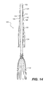
- the female piece 214 of the fixed grip 126 may receive the male piece 134 of the wringer 120 and retain it therein via an interference fit between the lip 136 of the male piece 134 and the inner rim 216 of the female piece 214 , as shown in FIG. 14 .
- the interference fit between the fixed grip 126 and the wringer 120 thereby ensures that as the operator is mopping, the wringer 120 will not unintentionally descend from the mopping position.
Abstract
Description
Claims (24)
Priority Applications (4)
| Application Number | Priority Date | Filing Date | Title |
|---|---|---|---|
| US11/754,717 US8011055B2 (en) | 2006-06-01 | 2007-05-29 | Cleaning implement |
| PCT/US2007/069961 WO2007143471A2 (en) | 2006-06-01 | 2007-05-30 | Cleaning implement with wringer |
| CA002653947A CA2653947A1 (en) | 2006-06-01 | 2007-05-30 | Cleaning implement |
| AU2007256896A AU2007256896A1 (en) | 2006-06-01 | 2007-05-30 | Cleaning implement with wringer |
Applications Claiming Priority (3)
| Application Number | Priority Date | Filing Date | Title |
|---|---|---|---|
| US81040506P | 2006-06-01 | 2006-06-01 | |
| US90594007P | 2007-03-09 | 2007-03-09 | |
| US11/754,717 US8011055B2 (en) | 2006-06-01 | 2007-05-29 | Cleaning implement |
Publications (2)
| Publication Number | Publication Date |
|---|---|
| US20080010768A1 US20080010768A1 (en) | 2008-01-17 |
| US8011055B2 true US8011055B2 (en) | 2011-09-06 |
Family
ID=38802219
Family Applications (1)
| Application Number | Title | Priority Date | Filing Date |
|---|---|---|---|
| US11/754,717 Active 2030-03-31 US8011055B2 (en) | 2006-06-01 | 2007-05-29 | Cleaning implement |
Country Status (4)
| Country | Link |
|---|---|
| US (1) | US8011055B2 (en) |
| AU (1) | AU2007256896A1 (en) |
| CA (1) | CA2653947A1 (en) |
| WO (1) | WO2007143471A2 (en) |
Cited By (11)
| Publication number | Priority date | Publication date | Assignee | Title |
|---|---|---|---|---|
| US20100287722A1 (en) * | 2009-05-14 | 2010-11-18 | Tsung Mou Yu | Mop With Spinning Device |
| USD667188S1 (en) * | 2011-01-13 | 2012-09-11 | The Libman Company | Mop |
| USD667189S1 (en) * | 2011-01-13 | 2012-09-11 | The Libman Company | Mop |
| US9510905B2 (en) | 2014-11-19 | 2016-12-06 | Advanced Cardiac Therapeutics, Inc. | Systems and methods for high-resolution mapping of tissue |
| US9517103B2 (en) | 2014-11-19 | 2016-12-13 | Advanced Cardiac Therapeutics, Inc. | Medical instruments with multiple temperature sensors |
| US9636164B2 (en) | 2015-03-25 | 2017-05-02 | Advanced Cardiac Therapeutics, Inc. | Contact sensing systems and methods |
| US9993178B2 (en) | 2016-03-15 | 2018-06-12 | Epix Therapeutics, Inc. | Methods of determining catheter orientation |
| US10166062B2 (en) | 2014-11-19 | 2019-01-01 | Epix Therapeutics, Inc. | High-resolution mapping of tissue with pacing |
| US20190125157A1 (en) * | 2017-10-31 | 2019-05-02 | Jiaxing Jackson Travel Products Co., Ltd. | Spin-dry mop |
| US10888373B2 (en) | 2017-04-27 | 2021-01-12 | Epix Therapeutics, Inc. | Contact assessment between an ablation catheter and tissue |
| US11957289B1 (en) | 2021-07-15 | 2024-04-16 | Lynn A. Winter | Vehicle washing mitt for a broom |
Families Citing this family (5)
| Publication number | Priority date | Publication date | Assignee | Title |
|---|---|---|---|---|
| US8402589B2 (en) | 2001-07-25 | 2013-03-26 | The Libman Company | Cleaning implement |
| US8302245B2 (en) * | 2007-12-31 | 2012-11-06 | The Libman Company | Retainer for mop |
| DE102009060008A1 (en) * | 2009-12-21 | 2011-06-22 | Carl Freudenberg KG, 69469 | cleaner |
| US11419472B2 (en) | 2020-03-13 | 2022-08-23 | The Libman Company | Cleaning implement |
| CN115365197B (en) * | 2022-09-01 | 2023-11-24 | 国网河南省电力公司宜阳县供电公司 | Substation video monitoring camera cleaning tool |
Citations (75)
| Publication number | Priority date | Publication date | Assignee | Title |
|---|---|---|---|---|
| US435976A (en) | 1890-09-09 | mullen | ||
| US1273768A (en) | 1917-10-19 | 1918-07-23 | Joseph E Gillam | Mop-wringer. |
| US3462788A (en) | 1968-04-19 | 1969-08-26 | Tom L Abbott | Mop wringer |
| GB1300709A (en) | 1971-11-19 | 1972-12-20 | Andrew Tsang Ng Fai | A mop |
| US3946457A (en) | 1974-03-22 | 1976-03-30 | S.A. Brush Company Limited | Mop wringer |
| US4130910A (en) | 1977-02-15 | 1978-12-26 | Raven Neil A | Wringer type mop |
| US4178650A (en) | 1979-01-02 | 1979-12-18 | Aasland Reuben E | Self-wringing mop |
| GB1577370A (en) | 1976-09-21 | 1980-10-22 | Heinonen A | Self-wringing mop |
| GB1586313A (en) | 1978-05-30 | 1981-03-18 | Sabco Ltd | Mop wringers |
| US4464807A (en) | 1982-06-21 | 1984-08-14 | Moulinex, Societe Anonyme | Floor mop |
| US4479278A (en) | 1982-02-27 | 1984-10-30 | Ahti Heinonen | Scrubbing means |
| EP0162815A1 (en) | 1984-04-17 | 1985-11-27 | Giorgio Trisolini | Improved floor-washing apparatus provided with a self-wringing device |
| DE3607121A1 (en) | 1986-03-05 | 1987-09-10 | Leifheit Ag | WIPER |
| US4809387A (en) | 1987-06-17 | 1989-03-07 | Yamazaki Corporation | Mop with squeezer |
| FR2622785A1 (en) | 1987-11-09 | 1989-05-12 | Spontex Sa | Device for wringing out a mop and mop fitted with the said device |
| USD311077S (en) | 1987-07-23 | 1990-10-02 | Yamazaki Corporation | Combined mop and wringer |
| US5060338A (en) | 1990-04-16 | 1991-10-29 | The Libman Company | Wet mop with self-contained wringer |
| WO1991019450A1 (en) | 1990-06-19 | 1991-12-26 | Manfred Klotz | Mop |
| WO1995007046A1 (en) | 1993-09-08 | 1995-03-16 | Unilever Plc | Mops |
| GB2285391A (en) | 1994-01-11 | 1995-07-12 | Peter Mckay | Twist action mop |
| DE29520612U1 (en) | 1995-12-28 | 1996-02-15 | Thomasson Stig Ola | Mop and wringing part for this |
| US5509163A (en) | 1995-03-29 | 1996-04-23 | Worldwide Integrated Resources, Inc. | Quick squeezing wringable mop |
| DE19524440C1 (en) | 1995-07-05 | 1996-08-08 | Gernot Hirse | Cleaning device with handle |
| US5566417A (en) | 1995-01-30 | 1996-10-22 | Hsieh; Stephen | Twistable wring mop with dual locking members |
| US5577290A (en) | 1995-12-13 | 1996-11-26 | Monahan; Patrick H. | Wet mop with self-contained wringer |
| US5642551A (en) | 1996-07-19 | 1997-07-01 | Easy Day Manufacturing Company | Twist mop |
| WO1997024973A1 (en) | 1996-01-11 | 1997-07-17 | Freudenberg Household Products Lp | Mop, mop element, and mop element assembly |
| USD384458S (en) | 1995-12-18 | 1997-09-30 | Vining Industries, Inc. | Wringer mop |
| US5675858A (en) | 1996-09-12 | 1997-10-14 | Von Meyer; Robert | String mop with wringer |
| USD387526S (en) | 1995-10-05 | 1997-12-09 | The Libman Company | Combined wringer hand grip, tubular shell, and collar for a mop |
| USD387527S (en) | 1996-09-03 | 1997-12-09 | M.B. Walton, Inc. | Mop |
| US5722105A (en) | 1995-12-28 | 1998-03-03 | Thomasson; Stig Ola | Floor mop and wringing mechanism therefor |
| US5724694A (en) | 1997-01-10 | 1998-03-10 | Lewis; Larry I. | Self-squeezing mop |
| ES2117588A1 (en) | 1997-01-02 | 1998-08-01 | Jimenez Juan Ruiz | Draining (wringing) system which comprises a cylinder for the compression and draining of waste |
| US5819356A (en) | 1996-07-19 | 1998-10-13 | Easy Day Manufacturing Company | Twist mop |
| US5875509A (en) | 1995-10-31 | 1999-03-02 | Facca; Andrew G. | Self-wringing mop |
| US5890253A (en) | 1997-12-09 | 1999-04-06 | Worldwide Integrated Resources, Inc. | Mop apparatus for unwinding the tangled strands of a mop head |
| US5894625A (en) | 1998-05-27 | 1999-04-20 | Quickie Manufacturing Corporation | Mop roller wringer |
| WO1999023930A1 (en) | 1997-11-12 | 1999-05-20 | Niccolai, Celestino | Device for wringing out a mop |
| US5907883A (en) | 1997-02-05 | 1999-06-01 | Thomasson; Stig Ola | Wringing method and wringing mechanism for floor mop |
| US5913347A (en) | 1997-10-21 | 1999-06-22 | Wilen Acquisition Corporation | Mop head with integral fused brush array |
| US5976266A (en) | 1996-10-09 | 1999-11-02 | Gsp Products, Inc. | Method for cleaning and wringing mop |
| US6006392A (en) | 1998-03-13 | 1999-12-28 | O-Cedar Brands, Inc. | Self-wringing mop |
| US6058549A (en) | 1996-02-19 | 2000-05-09 | Anthony Harold Milward-Bason | Twist mop |
| US6076220A (en) | 1998-12-10 | 2000-06-20 | Quickie Manufacturing Company | Mop roller wringer locking system |
| US6085378A (en) | 1999-07-12 | 2000-07-11 | Quickie Manufacturing Corporation | Self-wringing swab mop with scrubber |
| US6088867A (en) | 1998-11-13 | 2000-07-18 | Stefani; Sheri | Combined mop and brush assembly |
| US6108848A (en) | 1998-12-03 | 2000-08-29 | Monahan; Pat | Mop with self-contained wringer |
| US6115869A (en) | 1998-11-24 | 2000-09-12 | Libman; Robert J. | Wringer mop |
| US6125494A (en) | 1998-12-23 | 2000-10-03 | Worldwide Integrated Resources, Inc. | Self-wringing mop |
| US6212728B1 (en) | 1997-12-02 | 2001-04-10 | Multi-Reach, Inc. | Self-wringing ratchet mop |
| US6212727B1 (en) | 1999-08-20 | 2001-04-10 | Yarron Bendor | Twist-type mop |
| US6233775B1 (en) | 1997-12-08 | 2001-05-22 | Carl Freudenberg | Floor mopping device |
| US20020092105A1 (en) * | 2001-01-12 | 2002-07-18 | Christopher Laux | Mop with self-contained wringer sleeve |
| US6427280B1 (en) | 2000-03-02 | 2002-08-06 | Freudenberg Household Products | Cleaning implement |
| US20020129457A1 (en) | 2001-03-14 | 2002-09-19 | Xiaoping Wang | Self-wringing mop with rotating offset |
| US20020133892A1 (en) | 2001-03-26 | 2002-09-26 | Monahan Patrick H. | Mop with self-contained wringer |
| US20030000036A1 (en) | 2001-02-16 | 2003-01-02 | Jianhua Fan | Easy mop |
| US6526617B1 (en) | 1999-04-13 | 2003-03-04 | Firma Carl Freudenberg | Wet mop with a rotatable handle |
| US20030079307A1 (en) | 2001-10-25 | 2003-05-01 | Ng Kim Kwee | Mop with wringing operation |
| USD474869S1 (en) | 2001-07-25 | 2003-05-20 | The Libman Company | Mop |
| US6615437B1 (en) | 2000-04-12 | 2003-09-09 | May's Industries, Ltd. | Gear-enabled wringing device |
| DE10207384A1 (en) | 2002-02-21 | 2003-09-11 | Freudenberg Carl Kg | Self-wringing mop |
| US20030208867A1 (en) | 2002-05-07 | 2003-11-13 | O-Cedar Brands, Inc. | Self-wringing ratchet mop |
| US20030213079A1 (en) | 2001-07-25 | 2003-11-20 | Libman Robert J. | Mop with attached wringer cup |
| US20030226227A1 (en) | 2002-01-15 | 2003-12-11 | Multi-Reach Inc. | Mop swab and mop |
| US6675427B1 (en) | 2002-03-29 | 2004-01-13 | O-Cedar Brands, Inc. | Mop including a mop head having a scrub material |
| WO2004021851A1 (en) | 2002-09-03 | 2004-03-18 | Celestino Niccolai | Device for wringing out the material of domestic cleaning tools known as mops |
| WO2004023966A1 (en) | 2002-09-13 | 2004-03-25 | Freudenberg Household Products Lp | Twist mop |
| US20050022327A1 (en) | 2003-07-30 | 2005-02-03 | Flavio Cavalheiro | Twist mop |
| WO2005089619A1 (en) | 2004-03-18 | 2005-09-29 | Jerzy Perkitny | Mop with motorized wringing device |
| US20060016032A1 (en) * | 2001-07-25 | 2006-01-26 | The Libman Company | Mop with attached wringer |
| US20060016031A1 (en) | 2004-07-22 | 2006-01-26 | Llanes Joselito L | Cylinder attachment to wring water out of mop in pail with holding tray |
| US20060026785A1 (en) | 2004-08-05 | 2006-02-09 | Andre Sampaio | Wring mop |
| USD575468S1 (en) * | 2006-04-07 | 2008-08-19 | The Libman Company | Portion of a mop |
-
2007
- 2007-05-29 US US11/754,717 patent/US8011055B2/en active Active
- 2007-05-30 AU AU2007256896A patent/AU2007256896A1/en not_active Abandoned
- 2007-05-30 WO PCT/US2007/069961 patent/WO2007143471A2/en active Application Filing
- 2007-05-30 CA CA002653947A patent/CA2653947A1/en not_active Abandoned
Patent Citations (99)
| Publication number | Priority date | Publication date | Assignee | Title |
|---|---|---|---|---|
| US435976A (en) | 1890-09-09 | mullen | ||
| US1273768A (en) | 1917-10-19 | 1918-07-23 | Joseph E Gillam | Mop-wringer. |
| US3462788A (en) | 1968-04-19 | 1969-08-26 | Tom L Abbott | Mop wringer |
| GB1300709A (en) | 1971-11-19 | 1972-12-20 | Andrew Tsang Ng Fai | A mop |
| US3946457A (en) | 1974-03-22 | 1976-03-30 | S.A. Brush Company Limited | Mop wringer |
| GB1577370A (en) | 1976-09-21 | 1980-10-22 | Heinonen A | Self-wringing mop |
| US4130910A (en) | 1977-02-15 | 1978-12-26 | Raven Neil A | Wringer type mop |
| GB1548060A (en) | 1977-02-15 | 1979-07-04 | Raven Bros Pty Ltd | Mop |
| GB1586313A (en) | 1978-05-30 | 1981-03-18 | Sabco Ltd | Mop wringers |
| US4178650A (en) | 1979-01-02 | 1979-12-18 | Aasland Reuben E | Self-wringing mop |
| US4479278A (en) | 1982-02-27 | 1984-10-30 | Ahti Heinonen | Scrubbing means |
| US4464807A (en) | 1982-06-21 | 1984-08-14 | Moulinex, Societe Anonyme | Floor mop |
| EP0162815A1 (en) | 1984-04-17 | 1985-11-27 | Giorgio Trisolini | Improved floor-washing apparatus provided with a self-wringing device |
| DE3607121A1 (en) | 1986-03-05 | 1987-09-10 | Leifheit Ag | WIPER |
| US4809387A (en) | 1987-06-17 | 1989-03-07 | Yamazaki Corporation | Mop with squeezer |
| USD311077S (en) | 1987-07-23 | 1990-10-02 | Yamazaki Corporation | Combined mop and wringer |
| FR2622785A1 (en) | 1987-11-09 | 1989-05-12 | Spontex Sa | Device for wringing out a mop and mop fitted with the said device |
| US5060338A (en) | 1990-04-16 | 1991-10-29 | The Libman Company | Wet mop with self-contained wringer |
| WO1991019450A1 (en) | 1990-06-19 | 1991-12-26 | Manfred Klotz | Mop |
| DE4019480C1 (en) | 1990-06-19 | 1992-02-06 | Manfred 4790 Paderborn De Klotz | |
| WO1995007046A1 (en) | 1993-09-08 | 1995-03-16 | Unilever Plc | Mops |
| GB2285391A (en) | 1994-01-11 | 1995-07-12 | Peter Mckay | Twist action mop |
| WO1996020632A1 (en) | 1994-01-11 | 1996-07-11 | Peter Mckay | Improved twist action mop |
| US5566417A (en) | 1995-01-30 | 1996-10-22 | Hsieh; Stephen | Twistable wring mop with dual locking members |
| US5509163A (en) | 1995-03-29 | 1996-04-23 | Worldwide Integrated Resources, Inc. | Quick squeezing wringable mop |
| US5675857A (en) | 1995-07-05 | 1997-10-14 | Hirse; Gernot | Mop with a water-removal device |
| DE19524440C1 (en) | 1995-07-05 | 1996-08-08 | Gernot Hirse | Cleaning device with handle |
| USD387526S (en) | 1995-10-05 | 1997-12-09 | The Libman Company | Combined wringer hand grip, tubular shell, and collar for a mop |
| US5996161A (en) | 1995-10-31 | 1999-12-07 | Facca; Andrew G. | Self-wringing mop |
| US5875509A (en) | 1995-10-31 | 1999-03-02 | Facca; Andrew G. | Self-wringing mop |
| US5577290A (en) | 1995-12-13 | 1996-11-26 | Monahan; Patrick H. | Wet mop with self-contained wringer |
| USD384458S (en) | 1995-12-18 | 1997-09-30 | Vining Industries, Inc. | Wringer mop |
| DE29520612U1 (en) | 1995-12-28 | 1996-02-15 | Thomasson Stig Ola | Mop and wringing part for this |
| US5722105A (en) | 1995-12-28 | 1998-03-03 | Thomasson; Stig Ola | Floor mop and wringing mechanism therefor |
| US6378156B2 (en) | 1996-01-11 | 2002-04-30 | Freudenberg Household Products | Mop, mop element and mop element assembly |
| US20020108197A1 (en) * | 1996-01-11 | 2002-08-15 | Fredenberg Household Products Lp | Cleaning implement |
| US20010013150A1 (en) | 1996-01-11 | 2001-08-16 | Specht Paul B. | Mop, mop element and mop element assembly |
| US6240589B1 (en) | 1996-01-11 | 2001-06-05 | Freudenberg Household Products Lp | Mop, mop element, and mop element assembly |
| US6112358A (en) | 1996-01-11 | 2000-09-05 | Freudenberg Household Products, Lp | Mop, mop element and mop element assembly |
| US5850658A (en) | 1996-01-11 | 1998-12-22 | Freudenberg Houselhold Products Lp | Wringable mop |
| WO1997024973A1 (en) | 1996-01-11 | 1997-07-17 | Freudenberg Household Products Lp | Mop, mop element, and mop element assembly |
| US20030084530A1 (en) | 1996-01-11 | 2003-05-08 | Freudenberg Household Products Lp | Mop, mop element, and mop element assembly |
| US6058549A (en) | 1996-02-19 | 2000-05-09 | Anthony Harold Milward-Bason | Twist mop |
| US5642551A (en) | 1996-07-19 | 1997-07-01 | Easy Day Manufacturing Company | Twist mop |
| US5819356A (en) | 1996-07-19 | 1998-10-13 | Easy Day Manufacturing Company | Twist mop |
| USD387527S (en) | 1996-09-03 | 1997-12-09 | M.B. Walton, Inc. | Mop |
| US5675858A (en) | 1996-09-12 | 1997-10-14 | Von Meyer; Robert | String mop with wringer |
| US5976266A (en) | 1996-10-09 | 1999-11-02 | Gsp Products, Inc. | Method for cleaning and wringing mop |
| ES2117588A1 (en) | 1997-01-02 | 1998-08-01 | Jimenez Juan Ruiz | Draining (wringing) system which comprises a cylinder for the compression and draining of waste |
| US5724694A (en) | 1997-01-10 | 1998-03-10 | Lewis; Larry I. | Self-squeezing mop |
| US5907883A (en) | 1997-02-05 | 1999-06-01 | Thomasson; Stig Ola | Wringing method and wringing mechanism for floor mop |
| US5913347A (en) | 1997-10-21 | 1999-06-22 | Wilen Acquisition Corporation | Mop head with integral fused brush array |
| WO1999023930A1 (en) | 1997-11-12 | 1999-05-20 | Niccolai, Celestino | Device for wringing out a mop |
| EP1030586B1 (en) | 1997-11-14 | 2004-01-07 | Ola Thomasson | Wringing method and wringing mechanism for floor mop |
| US6212728B1 (en) | 1997-12-02 | 2001-04-10 | Multi-Reach, Inc. | Self-wringing ratchet mop |
| US6233775B1 (en) | 1997-12-08 | 2001-05-22 | Carl Freudenberg | Floor mopping device |
| US5890253A (en) | 1997-12-09 | 1999-04-06 | Worldwide Integrated Resources, Inc. | Mop apparatus for unwinding the tangled strands of a mop head |
| US6006392A (en) | 1998-03-13 | 1999-12-28 | O-Cedar Brands, Inc. | Self-wringing mop |
| US5894625A (en) | 1998-05-27 | 1999-04-20 | Quickie Manufacturing Corporation | Mop roller wringer |
| US6088867A (en) | 1998-11-13 | 2000-07-18 | Stefani; Sheri | Combined mop and brush assembly |
| US6115869A (en) | 1998-11-24 | 2000-09-12 | Libman; Robert J. | Wringer mop |
| US6108848A (en) | 1998-12-03 | 2000-08-29 | Monahan; Pat | Mop with self-contained wringer |
| US6076220A (en) | 1998-12-10 | 2000-06-20 | Quickie Manufacturing Company | Mop roller wringer locking system |
| US6125494A (en) | 1998-12-23 | 2000-10-03 | Worldwide Integrated Resources, Inc. | Self-wringing mop |
| US6526617B1 (en) | 1999-04-13 | 2003-03-04 | Firma Carl Freudenberg | Wet mop with a rotatable handle |
| US6085378A (en) | 1999-07-12 | 2000-07-11 | Quickie Manufacturing Corporation | Self-wringing swab mop with scrubber |
| US6212727B1 (en) | 1999-08-20 | 2001-04-10 | Yarron Bendor | Twist-type mop |
| US6427280B1 (en) | 2000-03-02 | 2002-08-06 | Freudenberg Household Products | Cleaning implement |
| US6615437B1 (en) | 2000-04-12 | 2003-09-09 | May's Industries, Ltd. | Gear-enabled wringing device |
| US20020092105A1 (en) * | 2001-01-12 | 2002-07-18 | Christopher Laux | Mop with self-contained wringer sleeve |
| US20030000036A1 (en) | 2001-02-16 | 2003-01-02 | Jianhua Fan | Easy mop |
| US6523211B2 (en) | 2001-03-14 | 2003-02-25 | Xiaoping Wang | Self-wringing mop with rotating offset |
| US20020129457A1 (en) | 2001-03-14 | 2002-09-19 | Xiaoping Wang | Self-wringing mop with rotating offset |
| US6477731B2 (en) * | 2001-03-26 | 2002-11-12 | Patrick H. Monahan | Mop with self-contained wringer |
| US20020133892A1 (en) | 2001-03-26 | 2002-09-26 | Monahan Patrick H. | Mop with self-contained wringer |
| US20060016032A1 (en) * | 2001-07-25 | 2006-01-26 | The Libman Company | Mop with attached wringer |
| USD474869S1 (en) | 2001-07-25 | 2003-05-20 | The Libman Company | Mop |
| US6920664B2 (en) | 2001-07-25 | 2005-07-26 | The Libman Company | Mop with attached wringer cup |
| USD522702S1 (en) | 2001-07-25 | 2006-06-06 | The Libman Company | Hand grip portion for a mop |
| US20030213079A1 (en) | 2001-07-25 | 2003-11-20 | Libman Robert J. | Mop with attached wringer cup |
| USD532569S1 (en) | 2001-07-25 | 2006-11-21 | The Libman Company | Hand grip for a mop |
| US20030079307A1 (en) | 2001-10-25 | 2003-05-01 | Ng Kim Kwee | Mop with wringing operation |
| US6745429B2 (en) | 2001-10-25 | 2004-06-08 | Kim Kwee Ng | Mop with wringing operation |
| US20030226227A1 (en) | 2002-01-15 | 2003-12-11 | Multi-Reach Inc. | Mop swab and mop |
| US20040006836A1 (en) | 2002-02-21 | 2004-01-15 | Carl Freudenberg Kg | Self-wringing mop |
| DE10207384A1 (en) | 2002-02-21 | 2003-09-11 | Freudenberg Carl Kg | Self-wringing mop |
| US6675427B1 (en) | 2002-03-29 | 2004-01-13 | O-Cedar Brands, Inc. | Mop including a mop head having a scrub material |
| US6732396B2 (en) | 2002-05-07 | 2004-05-11 | O-Cedar Brands, Inc. | Self-wringing ratchet mop |
| US20030208867A1 (en) | 2002-05-07 | 2003-11-13 | O-Cedar Brands, Inc. | Self-wringing ratchet mop |
| WO2004021851A1 (en) | 2002-09-03 | 2004-03-18 | Celestino Niccolai | Device for wringing out the material of domestic cleaning tools known as mops |
| US20060021171A1 (en) | 2002-09-03 | 2006-02-02 | Celestino Niccolai | Device for wringing out the material of domestic cleaning tools known as mops |
| WO2004023966A1 (en) | 2002-09-13 | 2004-03-25 | Freudenberg Household Products Lp | Twist mop |
| US20040128783A1 (en) | 2002-09-13 | 2004-07-08 | Freudenberg Household Products | Twist mop |
| WO2006025814A1 (en) | 2003-07-30 | 2006-03-09 | Kaminstein Imports, Inc. | Twist mop |
| US20050022327A1 (en) | 2003-07-30 | 2005-02-03 | Flavio Cavalheiro | Twist mop |
| WO2005089619A1 (en) | 2004-03-18 | 2005-09-29 | Jerzy Perkitny | Mop with motorized wringing device |
| US20060016031A1 (en) | 2004-07-22 | 2006-01-26 | Llanes Joselito L | Cylinder attachment to wring water out of mop in pail with holding tray |
| US20060026785A1 (en) | 2004-08-05 | 2006-02-09 | Andre Sampaio | Wring mop |
| USD575468S1 (en) * | 2006-04-07 | 2008-08-19 | The Libman Company | Portion of a mop |
Non-Patent Citations (1)
| Title |
|---|
| Patent Abstracts of Japan, JP 07-255658, Sep. 10, 1995. |
Cited By (31)
| Publication number | Priority date | Publication date | Assignee | Title |
|---|---|---|---|---|
| US20100287722A1 (en) * | 2009-05-14 | 2010-11-18 | Tsung Mou Yu | Mop With Spinning Device |
| US8214963B2 (en) * | 2009-05-14 | 2012-07-10 | Tsung Mou Yu | Mop with spinning device |
| USD667188S1 (en) * | 2011-01-13 | 2012-09-11 | The Libman Company | Mop |
| USD667189S1 (en) * | 2011-01-13 | 2012-09-11 | The Libman Company | Mop |
| US10383686B2 (en) | 2014-11-19 | 2019-08-20 | Epix Therapeutics, Inc. | Ablation systems with multiple temperature sensors |
| US10660701B2 (en) | 2014-11-19 | 2020-05-26 | Epix Therapeutics, Inc. | Methods of removing heat from an electrode using thermal shunting |
| US9522037B2 (en) | 2014-11-19 | 2016-12-20 | Advanced Cardiac Therapeutics, Inc. | Treatment adjustment based on temperatures from multiple temperature sensors |
| US9522036B2 (en) | 2014-11-19 | 2016-12-20 | Advanced Cardiac Therapeutics, Inc. | Ablation devices, systems and methods of using a high-resolution electrode assembly |
| US9592092B2 (en) | 2014-11-19 | 2017-03-14 | Advanced Cardiac Therapeutics, Inc. | Orientation determination based on temperature measurements |
| US11701171B2 (en) | 2014-11-19 | 2023-07-18 | Epix Therapeutics, Inc. | Methods of removing heat from an electrode using thermal shunting |
| US11642167B2 (en) | 2014-11-19 | 2023-05-09 | Epix Therapeutics, Inc. | Electrode assembly with thermal shunt member |
| US10166062B2 (en) | 2014-11-19 | 2019-01-01 | Epix Therapeutics, Inc. | High-resolution mapping of tissue with pacing |
| US10231779B2 (en) | 2014-11-19 | 2019-03-19 | Epix Therapeutics, Inc. | Ablation catheter with high-resolution electrode assembly |
| US11534227B2 (en) | 2014-11-19 | 2022-12-27 | Epix Therapeutics, Inc. | High-resolution mapping of tissue with pacing |
| US9510905B2 (en) | 2014-11-19 | 2016-12-06 | Advanced Cardiac Therapeutics, Inc. | Systems and methods for high-resolution mapping of tissue |
| US10413212B2 (en) | 2014-11-19 | 2019-09-17 | Epix Therapeutics, Inc. | Methods and systems for enhanced mapping of tissue |
| US10499983B2 (en) | 2014-11-19 | 2019-12-10 | Epix Therapeutics, Inc. | Ablation systems and methods using heat shunt networks |
| US9517103B2 (en) | 2014-11-19 | 2016-12-13 | Advanced Cardiac Therapeutics, Inc. | Medical instruments with multiple temperature sensors |
| US11135009B2 (en) | 2014-11-19 | 2021-10-05 | Epix Therapeutics, Inc. | Electrode assembly with thermal shunt member |
| US10675081B2 (en) | 2015-03-25 | 2020-06-09 | Epix Therapeutics, Inc. | Contact sensing systems and methods |
| US11576714B2 (en) | 2015-03-25 | 2023-02-14 | Epix Therapeutics, Inc. | Contact sensing systems and methods |
| US9636164B2 (en) | 2015-03-25 | 2017-05-02 | Advanced Cardiac Therapeutics, Inc. | Contact sensing systems and methods |
| US11179197B2 (en) | 2016-03-15 | 2021-11-23 | Epix Therapeutics, Inc. | Methods of determining catheter orientation |
| US11389230B2 (en) | 2016-03-15 | 2022-07-19 | Epix Therapeutics, Inc. | Systems for determining catheter orientation |
| US9993178B2 (en) | 2016-03-15 | 2018-06-12 | Epix Therapeutics, Inc. | Methods of determining catheter orientation |
| US10888373B2 (en) | 2017-04-27 | 2021-01-12 | Epix Therapeutics, Inc. | Contact assessment between an ablation catheter and tissue |
| US10893903B2 (en) | 2017-04-27 | 2021-01-19 | Epix Therapeutics, Inc. | Medical instruments having contact assessment features |
| US11617618B2 (en) | 2017-04-27 | 2023-04-04 | Epix Therapeutics, Inc. | Contact assessment between an ablation catheter and tissue |
| US10674886B2 (en) * | 2017-10-31 | 2020-06-09 | Jiaxing Jackson Travel Products Co., Ltd. | Spin-dry mop |
| US20190125157A1 (en) * | 2017-10-31 | 2019-05-02 | Jiaxing Jackson Travel Products Co., Ltd. | Spin-dry mop |
| US11957289B1 (en) | 2021-07-15 | 2024-04-16 | Lynn A. Winter | Vehicle washing mitt for a broom |
Also Published As
| Publication number | Publication date |
|---|---|
| WO2007143471A3 (en) | 2008-07-17 |
| US20080010768A1 (en) | 2008-01-17 |
| CA2653947A1 (en) | 2007-12-13 |
| WO2007143471A2 (en) | 2007-12-13 |
| AU2007256896A1 (en) | 2007-12-13 |
Similar Documents
| Publication | Publication Date | Title |
|---|---|---|
| US8011055B2 (en) | Cleaning implement | |
| US5060338A (en) | Wet mop with self-contained wringer | |
| US20090025163A1 (en) | Cleaning implement | |
| US8291538B2 (en) | Mop structure of converting vertical linear displacement into unidirectional rotation for dewatering a mop | |
| US6625838B2 (en) | Mop with self-contained wringer sleeve | |
| EP2891445B1 (en) | Rotatable mop structure | |
| US8756750B2 (en) | Mop wringer | |
| US8739347B2 (en) | Spiral drive mechanism and spin mop with the same | |
| EP1030586B1 (en) | Wringing method and wringing mechanism for floor mop | |
| US9032579B1 (en) | Spin mop | |
| US8978193B2 (en) | Spin mop | |
| CN104997471B (en) | A kind of mop capable of twisting water | |
| AU2012207020A1 (en) | Cleaning implement with wringer | |
| US7089622B2 (en) | Wring mop | |
| TWM281504U (en) | Cleaning brush structure | |
| AU738062B2 (en) | Mop with handle | |
| KR200446498Y1 (en) | Push Stick With a Duster for Cleaning a Floor | |
| CN102670143B (en) | Burnisher | |
| US20060021171A1 (en) | Device for wringing out the material of domestic cleaning tools known as mops | |
| US20120167320A1 (en) | Roller for a cleaning device | |
| US3213475A (en) | Cleaning implement having an improved hand grip portion and mop head securing means | |
| KR200451307Y1 (en) | Rotating Dewatering Mop | |
| CN220175060U (en) | Water removal device and cleaning device comprising same | |
| GB2285391A (en) | Twist action mop | |
| CN213429642U (en) | Liquid heating container |
Legal Events
| Date | Code | Title | Description |
|---|---|---|---|
| AS | Assignment |
Owner name: PACESETTER, INC., CALIFORNIA Free format text: ASSIGNMENT OF ASSIGNORS INTEREST;ASSIGNORS:PERSSON, BENJAMIN T.;PANESCU, DORIN;ANDERSEN, DEAN;REEL/FRAME:019310/0469;SIGNING DATES FROM 20070507 TO 20070509 Owner name: PACESETTER, INC., CALIFORNIA Free format text: ASSIGNMENT OF ASSIGNORS INTEREST;ASSIGNORS:PERSSON, BENJAMIN T.;PANESCU, DORIN;ANDERSEN, DEAN;SIGNING DATES FROM 20070507 TO 20070509;REEL/FRAME:019310/0469 |
|
| AS | Assignment |
Owner name: CARL FREUDENBERG KG, GERMANY Free format text: ASSIGNMENT OF ASSIGNORS INTEREST;ASSIGNOR:LESLEY, PAUL M.;REEL/FRAME:019868/0554 Effective date: 20070901 |
|
| FEPP | Fee payment procedure |
Free format text: PAYOR NUMBER ASSIGNED (ORIGINAL EVENT CODE: ASPN); ENTITY STATUS OF PATENT OWNER: LARGE ENTITY |
|
| STCF | Information on status: patent grant |
Free format text: PATENTED CASE |
|
| FPAY | Fee payment |
Year of fee payment: 4 |
|
| FEPP | Fee payment procedure |
Free format text: 7.5 YR SURCHARGE - LATE PMT W/IN 6 MO, LARGE ENTITY (ORIGINAL EVENT CODE: M1555); ENTITY STATUS OF PATENT OWNER: LARGE ENTITY |
|
| MAFP | Maintenance fee payment |
Free format text: PAYMENT OF MAINTENANCE FEE, 8TH YEAR, LARGE ENTITY (ORIGINAL EVENT CODE: M1552); ENTITY STATUS OF PATENT OWNER: LARGE ENTITY Year of fee payment: 8 |
|
| MAFP | Maintenance fee payment |
Free format text: PAYMENT OF MAINTENANCE FEE, 12TH YEAR, LARGE ENTITY (ORIGINAL EVENT CODE: M1553); ENTITY STATUS OF PATENT OWNER: LARGE ENTITY Year of fee payment: 12 |