EP3750500B1 - Contact sensing systems - Google Patents
Contact sensing systems Download PDFInfo
- Publication number
- EP3750500B1 EP3750500B1 EP20171803.8A EP20171803A EP3750500B1 EP 3750500 B1 EP3750500 B1 EP 3750500B1 EP 20171803 A EP20171803 A EP 20171803A EP 3750500 B1 EP3750500 B1 EP 3750500B1
- Authority
- EP
- European Patent Office
- Prior art keywords
- contact
- frequency
- impedance
- khz
- tissue
- Prior art date
- Legal status (The legal status is an assumption and is not a legal conclusion. Google has not performed a legal analysis and makes no representation as to the accuracy of the status listed.)
- Active
Links
- 238000002847 impedance measurement Methods 0.000 claims description 153
- 238000002679 ablation Methods 0.000 claims description 86
- 238000001514 detection method Methods 0.000 claims description 35
- 230000000694 effects Effects 0.000 claims description 35
- 230000004044 response Effects 0.000 claims description 25
- 230000033001 locomotion Effects 0.000 claims description 24
- 210000001519 tissue Anatomy 0.000 description 241
- 238000005259 measurement Methods 0.000 description 126
- 238000000034 method Methods 0.000 description 98
- 238000012545 processing Methods 0.000 description 90
- 230000006870 function Effects 0.000 description 60
- 210000004369 blood Anatomy 0.000 description 34
- 239000008280 blood Substances 0.000 description 34
- 239000003990 capacitor Substances 0.000 description 34
- 239000012530 fluid Substances 0.000 description 24
- 238000013507 mapping Methods 0.000 description 24
- 230000008569 process Effects 0.000 description 24
- 238000013461 design Methods 0.000 description 23
- 238000001914 filtration Methods 0.000 description 23
- 210000005003 heart tissue Anatomy 0.000 description 17
- 238000003973 irrigation Methods 0.000 description 17
- 230000002262 irrigation Effects 0.000 description 16
- FAPWRFPIFSIZLT-UHFFFAOYSA-M Sodium chloride Chemical compound [Na+].[Cl-] FAPWRFPIFSIZLT-UHFFFAOYSA-M 0.000 description 13
- 239000011780 sodium chloride Substances 0.000 description 13
- 238000009529 body temperature measurement Methods 0.000 description 11
- 238000004422 calculation algorithm Methods 0.000 description 11
- 230000000747 cardiac effect Effects 0.000 description 10
- 239000004020 conductor Substances 0.000 description 9
- 238000010438 heat treatment Methods 0.000 description 9
- 230000007246 mechanism Effects 0.000 description 9
- 238000004891 communication Methods 0.000 description 8
- 239000011159 matrix material Substances 0.000 description 8
- 230000008859 change Effects 0.000 description 7
- 238000007674 radiofrequency ablation Methods 0.000 description 7
- 230000009471 action Effects 0.000 description 6
- 230000008878 coupling Effects 0.000 description 6
- 238000010168 coupling process Methods 0.000 description 6
- 238000005859 coupling reaction Methods 0.000 description 6
- 238000002001 electrophysiology Methods 0.000 description 6
- 230000007831 electrophysiology Effects 0.000 description 6
- 230000000007 visual effect Effects 0.000 description 6
- 238000004458 analytical method Methods 0.000 description 5
- 208000037265 diseases, disorders, signs and symptoms Diseases 0.000 description 5
- 230000005284 excitation Effects 0.000 description 5
- 239000004696 Poly ether ether ketone Substances 0.000 description 4
- 210000003484 anatomy Anatomy 0.000 description 4
- 238000013459 approach Methods 0.000 description 4
- -1 for example Chemical class 0.000 description 4
- 239000000203 mixture Substances 0.000 description 4
- 229920002530 polyetherether ketone Polymers 0.000 description 4
- 230000000638 stimulation Effects 0.000 description 4
- 230000008901 benefit Effects 0.000 description 3
- 230000005540 biological transmission Effects 0.000 description 3
- 239000003086 colorant Substances 0.000 description 3
- 230000001934 delay Effects 0.000 description 3
- 201000010099 disease Diseases 0.000 description 3
- 239000012777 electrically insulating material Substances 0.000 description 3
- 210000003743 erythrocyte Anatomy 0.000 description 3
- 230000003902 lesion Effects 0.000 description 3
- 239000012528 membrane Substances 0.000 description 3
- 229910052751 metal Inorganic materials 0.000 description 3
- 239000002184 metal Substances 0.000 description 3
- 238000012986 modification Methods 0.000 description 3
- 230000004048 modification Effects 0.000 description 3
- 229920006324 polyoxymethylene Polymers 0.000 description 3
- 238000000926 separation method Methods 0.000 description 3
- 238000001228 spectrum Methods 0.000 description 3
- 238000012546 transfer Methods 0.000 description 3
- 238000002604 ultrasonography Methods 0.000 description 3
- 208000033988 Device pacing issue Diseases 0.000 description 2
- 206010028980 Neoplasm Diseases 0.000 description 2
- 239000004809 Teflon Substances 0.000 description 2
- 229920006362 Teflon® Polymers 0.000 description 2
- 239000000956 alloy Substances 0.000 description 2
- 229910045601 alloy Inorganic materials 0.000 description 2
- 230000000712 assembly Effects 0.000 description 2
- 238000000429 assembly Methods 0.000 description 2
- 230000001746 atrial effect Effects 0.000 description 2
- 230000006399 behavior Effects 0.000 description 2
- 230000015572 biosynthetic process Effects 0.000 description 2
- 230000000903 blocking effect Effects 0.000 description 2
- 238000004364 calculation method Methods 0.000 description 2
- 238000013153 catheter ablation Methods 0.000 description 2
- 210000004027 cell Anatomy 0.000 description 2
- 238000012790 confirmation Methods 0.000 description 2
- 238000013500 data storage Methods 0.000 description 2
- 230000003247 decreasing effect Effects 0.000 description 2
- 230000001419 dependent effect Effects 0.000 description 2
- 238000003745 diagnosis Methods 0.000 description 2
- 238000010586 diagram Methods 0.000 description 2
- 229910003460 diamond Inorganic materials 0.000 description 2
- 239000010432 diamond Substances 0.000 description 2
- 208000035475 disorder Diseases 0.000 description 2
- 210000001174 endocardium Anatomy 0.000 description 2
- 208000021302 gastroesophageal reflux disease Diseases 0.000 description 2
- 230000012010 growth Effects 0.000 description 2
- 210000002216 heart Anatomy 0.000 description 2
- 210000002064 heart cell Anatomy 0.000 description 2
- 238000003384 imaging method Methods 0.000 description 2
- 239000000463 material Substances 0.000 description 2
- 150000002739 metals Chemical class 0.000 description 2
- 238000012544 monitoring process Methods 0.000 description 2
- 210000004165 myocardium Anatomy 0.000 description 2
- 230000003287 optical effect Effects 0.000 description 2
- 210000000056 organ Anatomy 0.000 description 2
- 238000013021 overheating Methods 0.000 description 2
- 230000010363 phase shift Effects 0.000 description 2
- BASFCYQUMIYNBI-UHFFFAOYSA-N platinum Chemical compound [Pt] BASFCYQUMIYNBI-UHFFFAOYSA-N 0.000 description 2
- 230000001105 regulatory effect Effects 0.000 description 2
- 238000005316 response function Methods 0.000 description 2
- 239000000523 sample Substances 0.000 description 2
- 239000013598 vector Substances 0.000 description 2
- 230000002861 ventricular Effects 0.000 description 2
- 206010003658 Atrial Fibrillation Diseases 0.000 description 1
- 238000012935 Averaging Methods 0.000 description 1
- 208000006545 Chronic Obstructive Pulmonary Disease Diseases 0.000 description 1
- RYGMFSIKBFXOCR-UHFFFAOYSA-N Copper Chemical compound [Cu] RYGMFSIKBFXOCR-UHFFFAOYSA-N 0.000 description 1
- 230000005355 Hall effect Effects 0.000 description 1
- 206010019280 Heart failures Diseases 0.000 description 1
- 206010020772 Hypertension Diseases 0.000 description 1
- 208000008589 Obesity Diseases 0.000 description 1
- 229930040373 Paraformaldehyde Natural products 0.000 description 1
- 239000004697 Polyetherimide Substances 0.000 description 1
- 239000004642 Polyimide Substances 0.000 description 1
- 206010056342 Pulmonary mass Diseases 0.000 description 1
- 208000001647 Renal Insufficiency Diseases 0.000 description 1
- 230000001594 aberrant effect Effects 0.000 description 1
- 230000002159 abnormal effect Effects 0.000 description 1
- 239000011354 acetal resin Substances 0.000 description 1
- 230000002411 adverse Effects 0.000 description 1
- 206010003119 arrhythmia Diseases 0.000 description 1
- 210000001367 artery Anatomy 0.000 description 1
- 208000006673 asthma Diseases 0.000 description 1
- 210000004556 brain Anatomy 0.000 description 1
- 229910010293 ceramic material Inorganic materials 0.000 description 1
- 238000012512 characterization method Methods 0.000 description 1
- 230000000052 comparative effect Effects 0.000 description 1
- 238000004590 computer program Methods 0.000 description 1
- 229910052802 copper Inorganic materials 0.000 description 1
- 239000010949 copper Substances 0.000 description 1
- 230000007423 decrease Effects 0.000 description 1
- 230000000593 degrading effect Effects 0.000 description 1
- 230000002638 denervation Effects 0.000 description 1
- 230000001627 detrimental effect Effects 0.000 description 1
- 206010012601 diabetes mellitus Diseases 0.000 description 1
- 230000009977 dual effect Effects 0.000 description 1
- 239000003792 electrolyte Substances 0.000 description 1
- 230000007613 environmental effect Effects 0.000 description 1
- 210000003238 esophagus Anatomy 0.000 description 1
- 230000008713 feedback mechanism Effects 0.000 description 1
- 210000000232 gallbladder Anatomy 0.000 description 1
- 210000001035 gastrointestinal tract Anatomy 0.000 description 1
- PCHJSUWPFVWCPO-UHFFFAOYSA-N gold Chemical compound [Au] PCHJSUWPFVWCPO-UHFFFAOYSA-N 0.000 description 1
- 229910052737 gold Inorganic materials 0.000 description 1
- 239000010931 gold Substances 0.000 description 1
- 238000009499 grossing Methods 0.000 description 1
- 210000002837 heart atrium Anatomy 0.000 description 1
- 208000019622 heart disease Diseases 0.000 description 1
- 230000006872 improvement Effects 0.000 description 1
- 230000002401 inhibitory effect Effects 0.000 description 1
- 230000000977 initiatory effect Effects 0.000 description 1
- 238000003780 insertion Methods 0.000 description 1
- 230000037431 insertion Effects 0.000 description 1
- 239000012774 insulation material Substances 0.000 description 1
- 201000006370 kidney failure Diseases 0.000 description 1
- 238000012830 laparoscopic surgical procedure Methods 0.000 description 1
- 230000000670 limiting effect Effects 0.000 description 1
- 208000005907 mitral valve insufficiency Diseases 0.000 description 1
- 210000005036 nerve Anatomy 0.000 description 1
- 210000000944 nerve tissue Anatomy 0.000 description 1
- 235000020824 obesity Nutrition 0.000 description 1
- 238000002355 open surgical procedure Methods 0.000 description 1
- 238000005457 optimization Methods 0.000 description 1
- 230000036961 partial effect Effects 0.000 description 1
- 230000037361 pathway Effects 0.000 description 1
- 230000008447 perception Effects 0.000 description 1
- 229910052697 platinum Inorganic materials 0.000 description 1
- HWLDNSXPUQTBOD-UHFFFAOYSA-N platinum-iridium alloy Chemical compound [Ir].[Pt] HWLDNSXPUQTBOD-UHFFFAOYSA-N 0.000 description 1
- 229920001601 polyetherimide Polymers 0.000 description 1
- 229920001721 polyimide Polymers 0.000 description 1
- 210000002307 prostate Anatomy 0.000 description 1
- 230000002685 pulmonary effect Effects 0.000 description 1
- 210000003492 pulmonary vein Anatomy 0.000 description 1
- 230000009467 reduction Effects 0.000 description 1
- 230000002829 reductive effect Effects 0.000 description 1
- 238000009877 rendering Methods 0.000 description 1
- 239000011347 resin Substances 0.000 description 1
- 229920005989 resin Polymers 0.000 description 1
- 208000023504 respiratory system disease Diseases 0.000 description 1
- 230000004043 responsiveness Effects 0.000 description 1
- 230000002441 reversible effect Effects 0.000 description 1
- 238000005070 sampling Methods 0.000 description 1
- 230000035807 sensation Effects 0.000 description 1
- 210000005070 sphincter Anatomy 0.000 description 1
- 229910001220 stainless steel Inorganic materials 0.000 description 1
- 239000010935 stainless steel Substances 0.000 description 1
- 230000001225 therapeutic effect Effects 0.000 description 1
- 238000002560 therapeutic procedure Methods 0.000 description 1
- 210000003708 urethra Anatomy 0.000 description 1
- 210000001635 urinary tract Anatomy 0.000 description 1
- 210000004291 uterus Anatomy 0.000 description 1
- 210000005166 vasculature Anatomy 0.000 description 1
- 210000003462 vein Anatomy 0.000 description 1
Images


Classifications
-
- A—HUMAN NECESSITIES
- A61—MEDICAL OR VETERINARY SCIENCE; HYGIENE
- A61B—DIAGNOSIS; SURGERY; IDENTIFICATION
- A61B18/00—Surgical instruments, devices or methods for transferring non-mechanical forms of energy to or from the body
- A61B18/04—Surgical instruments, devices or methods for transferring non-mechanical forms of energy to or from the body by heating
- A61B18/12—Surgical instruments, devices or methods for transferring non-mechanical forms of energy to or from the body by heating by passing a current through the tissue to be heated, e.g. high-frequency current
- A61B18/14—Probes or electrodes therefor
- A61B18/1492—Probes or electrodes therefor having a flexible, catheter-like structure, e.g. for heart ablation
-
- A—HUMAN NECESSITIES
- A61—MEDICAL OR VETERINARY SCIENCE; HYGIENE
- A61B—DIAGNOSIS; SURGERY; IDENTIFICATION
- A61B5/00—Measuring for diagnostic purposes; Identification of persons
- A61B5/68—Arrangements of detecting, measuring or recording means, e.g. sensors, in relation to patient
- A61B5/6846—Arrangements of detecting, measuring or recording means, e.g. sensors, in relation to patient specially adapted to be brought in contact with an internal body part, i.e. invasive
- A61B5/6885—Monitoring or controlling sensor contact pressure
-
- A—HUMAN NECESSITIES
- A61—MEDICAL OR VETERINARY SCIENCE; HYGIENE
- A61B—DIAGNOSIS; SURGERY; IDENTIFICATION
- A61B18/00—Surgical instruments, devices or methods for transferring non-mechanical forms of energy to or from the body
- A61B2018/00053—Mechanical features of the instrument of device
- A61B2018/00297—Means for providing haptic feedback
-
- A—HUMAN NECESSITIES
- A61—MEDICAL OR VETERINARY SCIENCE; HYGIENE
- A61B—DIAGNOSIS; SURGERY; IDENTIFICATION
- A61B18/00—Surgical instruments, devices or methods for transferring non-mechanical forms of energy to or from the body
- A61B2018/00636—Sensing and controlling the application of energy
- A61B2018/00773—Sensed parameters
- A61B2018/00827—Current
-
- A—HUMAN NECESSITIES
- A61—MEDICAL OR VETERINARY SCIENCE; HYGIENE
- A61B—DIAGNOSIS; SURGERY; IDENTIFICATION
- A61B18/00—Surgical instruments, devices or methods for transferring non-mechanical forms of energy to or from the body
- A61B2018/00636—Sensing and controlling the application of energy
- A61B2018/00773—Sensed parameters
- A61B2018/00875—Resistance or impedance
-
- A—HUMAN NECESSITIES
- A61—MEDICAL OR VETERINARY SCIENCE; HYGIENE
- A61B—DIAGNOSIS; SURGERY; IDENTIFICATION
- A61B18/00—Surgical instruments, devices or methods for transferring non-mechanical forms of energy to or from the body
- A61B2018/00636—Sensing and controlling the application of energy
- A61B2018/00773—Sensed parameters
- A61B2018/00892—Voltage
-
- A—HUMAN NECESSITIES
- A61—MEDICAL OR VETERINARY SCIENCE; HYGIENE
- A61B—DIAGNOSIS; SURGERY; IDENTIFICATION
- A61B18/00—Surgical instruments, devices or methods for transferring non-mechanical forms of energy to or from the body
- A61B18/04—Surgical instruments, devices or methods for transferring non-mechanical forms of energy to or from the body by heating
- A61B18/12—Surgical instruments, devices or methods for transferring non-mechanical forms of energy to or from the body by heating by passing a current through the tissue to be heated, e.g. high-frequency current
- A61B18/1206—Generators therefor
- A61B2018/128—Generators therefor generating two or more frequencies
-
- A—HUMAN NECESSITIES
- A61—MEDICAL OR VETERINARY SCIENCE; HYGIENE
- A61B—DIAGNOSIS; SURGERY; IDENTIFICATION
- A61B90/00—Instruments, implements or accessories specially adapted for surgery or diagnosis and not covered by any of the groups A61B1/00 - A61B50/00, e.g. for luxation treatment or for protecting wound edges
- A61B90/06—Measuring instruments not otherwise provided for
- A61B2090/064—Measuring instruments not otherwise provided for for measuring force, pressure or mechanical tension
- A61B2090/065—Measuring instruments not otherwise provided for for measuring force, pressure or mechanical tension for measuring contact or contact pressure
-
- A—HUMAN NECESSITIES
- A61—MEDICAL OR VETERINARY SCIENCE; HYGIENE
- A61B—DIAGNOSIS; SURGERY; IDENTIFICATION
- A61B5/00—Measuring for diagnostic purposes; Identification of persons
- A61B5/05—Detecting, measuring or recording for diagnosis by means of electric currents or magnetic fields; Measuring using microwaves or radio waves
- A61B5/053—Measuring electrical impedance or conductance of a portion of the body
-
- A—HUMAN NECESSITIES
- A61—MEDICAL OR VETERINARY SCIENCE; HYGIENE
- A61B—DIAGNOSIS; SURGERY; IDENTIFICATION
- A61B5/00—Measuring for diagnostic purposes; Identification of persons
- A61B5/24—Detecting, measuring or recording bioelectric or biomagnetic signals of the body or parts thereof
- A61B5/25—Bioelectric electrodes therefor
- A61B5/279—Bioelectric electrodes therefor specially adapted for particular uses
- A61B5/28—Bioelectric electrodes therefor specially adapted for particular uses for electrocardiography [ECG]
- A61B5/283—Invasive
- A61B5/287—Holders for multiple electrodes, e.g. electrode catheters for electrophysiological study [EPS]
Definitions
- Tissue ablation may be used to treat a variety of clinical disorders.
- tissue ablation may be used to treat cardiac arrhythmias by destroying (for example, at least partially or completely ablating, interrupting, inhibiting, terminating conduction of, otherwise affecting, etc.) aberrant pathways that would otherwise conduct abnormal electrical signals to the heart muscle.
- ablation techniques including cryoablation, microwave ablation, radiofrequency (RF) ablation, and high frequency ultrasound ablation.
- such techniques are typically performed by a clinician who introduces a catheter having an ablative tip to the endocardium via the venous vasculature, positions the ablative tip adjacent to what the clinician believes to be an appropriate region of the endocardium based on tactile feedback, mapping electrocardiogram (ECG) signals, anatomy, and/or fluoroscopic imaging, actuates flow of an irrigant to cool the surface of the selected region, and then actuates the ablative tip for a period of time and at a power believed sufficient to destroy tissue in the selected region.
- ECG mapping electrocardiogram
- the clinician strives to establish stable and uniform contact between the electrode(s) and the tissue to be ablated.
- WO 2013/101923 A1 relates to a system for diagnosis or treatment of tissue in a body, and in particular to a system for optimizing the degree of mechanical and/or electrical coupling between an ablation catheter and tissue and for evaluating lesions in the tissue created by the ablation catheter.
- US 2013/324993 A1 relates to systems and methods for radiometrically measuring temperature and detecting tissue contact during ablation.
- EP 2700373 A1 relates to tissue ablation systems and in particular to monitoring of contact between an invasive probe and tissue within the body.
- the present invention relates to a medical treatment system comprising:
- systems and methods are provided for assessing or determining a level or quality of contact between a distal end portion of a medical instrument (such as an ablation catheter) and a target region (such as cardiac tissue or other body tissue).
- the contact assessment or determination may be performed prior to delivery of ablative energy to cardiac tissue so or may be performed during energy delivery so as to increase the likelihood that a treatment procedure (for example, lesion formation) is effective and to promote safety (for example, to avoid perforation, overheating or other damage to the target region).
- the contact assessment or determination may be performed by a contact sensing subsystem of an overall treatment system and may be executed by a processor that is specifically configured to execute program instructions stored on a computer-readable medium.
- a signal source of the contact sensing subsystem may be configured to generate one or more signals at at least two different frequencies and to apply the signals across a pair of electrode members separated by a gap positioned along the distal end portion of the medical instrument. Electrical measurements (such as voltage and/or current measurements or impedance measurements) may be obtained between the pair of electrode members and the level or quality of contact between the distal end portion of the medical instrument and the target region may be determined (for example, calculated) based, at least in part, on the electrical measurements.
- bipolar contact impedance magnitude is determined at a first frequency
- bipolar contact phase angle is determined at a second frequency
- the slope between bipolar contact impedance magnitude is determined between the first frequency and the second frequency and a combination of the determinations is used to generate an overall assessment of contact quality.
- a real-time indicator of the contact quality may be output on a display for a physician or other clinical professional to easily view and to which the physician or other clinical professional can easily react or respond.
- a system comprises at least one signal source configured to deliver at least a first frequency and a second frequency to a pair of electrodes or electrode portions of a combination electrode or electrode assembly.
- the system also comprises a processing device configured to: obtain electrical measurements while the first frequency and the second frequency are being applied to the pair of electrodes by the signal source, process the electrical (for example, voltage, current, impedance) measurements obtained at the first frequency and the second frequency, and determine whether the pair of electrodes is in contact with tissue based on said processing of the electrical (for example, impedance) measurements.
- the pair of electrodes may be positioned along a medical instrument (for example, at a distal end portion of an ablation catheter).
- the pair of electrodes may comprise radiofrequency electrodes and the at least one signal source may comprise one, two or more sources of radiofrequency energy.
- the signal source may comprise a first signal source configured to generate, deliver or apply signals to the pair of electrodes having a frequency configured for tissue ablation and a second signal source configured to generate, deliver or apply signals to the pair of electrodes having frequencies adapted for contact sensing and/or tissue type determination (for example, whether the tissue is ablated or still viable).
- the first and second signal sources may be integrated within an energy delivery module (for example, RF generator) or within an elongate body or handle of a medical instrument (for example, ablation catheter).
- the second signal source is within a contact sensing subsystem, which may be a distinct and separate component from the energy delivery module and medical instrument or integrated within the energy delivery module or medical instrument.
- the system comprises an energy source configured to generate, deliver or apply signals to at least a pair of electrode members (and also to a ground pad or reference electrode) to deliver energy having a frequency configured for tissue ablation or other treatment and a signal source configured to generate, deliver or apply signals to the pair of electrode members (and not to a ground pad or reference electrode) having frequencies adapted for contact sensing and/or tissue type determination (for example, whether the tissue is ablated or still viable).
- the signals generated by the signal source may comprise constant current AC excitation signals or AC voltage excitation signals.
- the excitation signals may advantageously be outside the frequency range of the ablative frequencies and/or electrogram mapping frequencies.
- the energy source and the signal source may both be integrated within an energy delivery module (for example, RF generator) or one of the sources (for example, the signal source) may be incorporated within an elongate body or handle of a medical instrument (for example, ablation catheter).
- the signal source is within a contact sensing subsystem, which may be a distinct and separate component from the energy delivery module and medical instrument or integrated within the energy delivery module or medical instrument.
- a single source configured for applying signals having frequencies adapted for ablation or other treatment and configured for applying signals having frequencies adapted for contact sensing or tissue type determination functions is used.
- Signals having the treatment frequencies may also be delivered to a ground pad or reference electrode.
- the system consists essentially of or comprises a medical instrument (for example, an energy delivery device), one or more energy sources, one or more signal sources and one or more processing devices.
- the medical instrument for example, energy delivery catheter
- the medical instrument may comprise an elongate body having a proximal end and a distal end and a pair of electrodes or electrode portions (for example, a combination, or split-tip, electrode assembly) positioned at the distal end of the elongate body.
- the pair of electrodes comprises or consists essentially of a first electrode positioned on the elongate body and a second electrode positioned adjacent (for example, proximal of) the first electrode.
- the first electrode and the second electrode may be adapted to contact tissue of a subject and provide energy to the tissue to heat (for example, ablate or otherwise treat) the tissue at a depth from the surface of the tissue.
- the pair of electrodes comprises an electrically insulating gap positioned between the first electrode and the second electrode, the electrically insulating gap comprising a gap width separating the first and second electrodes.
- a separator (for example, a capacitor or insulation material) may be positioned within the electrically insulating gap.
- the one or more signal sources may be configured to deliver signals over a range of frequencies (for example, frequencies within a radiofrequency range).
- the processing device is configured to execute specific program instructions stored on a non-transitory computer-readable storage medium to: obtain impedance or other electrical measurements while different frequencies of energy within the range of frequencies are being applied to the pair of electrodes by a signal source, process the impedance or other electrical measurements obtained at the first frequency and the second frequency, and determine whether at least one of (for example, the distal-most electrode) the pair of electrodes is in contact with tissue based on said processing of the impedance or other electrical measurements.
- the impedance measurements constitute bipolar contact impedance between the pair of electrodes or between the electrode members of a combination electrode assembly and not the impedance between an electrode and target tissue.
- the impedance or other electrical measurements do not involve passing current to one or more patch or reference electrodes positioned at a location external to the medical instrument or at a location remote from the target tissue (for example, at a location on the skin of a patient at the neck, torso and/or leg).
- the medical instrument consists essentially of or comprises a radiofrequency ablation catheter and the first and second electrodes or electrode portions comprise radiofrequency electrodes.
- the signal source(s) may comprise a radiofrequency (RF) generator.
- the range of frequencies that is delivered by the signal source(s) comprises at least a range between 1 kHz and 5 MHz (for example, between 5 kHz and 1000 kHz, between 10 kHz and 500 kHz, between 5 kHz and 800 kHz, between 20 kHz and 800 kHz, between 50 kHz and 5 MHz, between 100 kHz and 1000 kHz, and overlapping ranges thereof).
- the signal source(s) may also be configured to deliver frequencies below and above this range.
- the frequencies may be at least greater than five times or at least greater than ten times the electrogram mapping frequencies so as not to interfere with high-resolution mapping images or functions obtained by the first and second electrodes or electrode portions.
- the different frequencies at which impedance measurements are obtained consists only of two discrete frequencies.
- the different frequencies comprise two or more discrete frequencies.
- the processing device is configured to obtain impedance measurements while a full sweep of frequencies from a minimum frequency to a maximum frequency of the range of frequencies is applied to the pair of electrodes or electrode portions.
- the range of frequencies is between 5 kHz and 1000 kHz.
- the second frequency may be different from (for example, higher or lower than) the first frequency.
- the frequencies used for contact sensing or determination are outside (for example, below) the frequency range of the ablative frequencies.
- the system may comprise an ablative energy source (for example, signal source such as an RF generator) configured to deliver signals to the pair of electrodes (and possibly also to a ground pad or reference electrode) to generate energy sufficient to ablate or otherwise treat tissue (such as cardiac tissue).
- the processing device is configured to adjust one or more energy delivery parameters of the ablative energy based on a determination of whether at least one of the pair of electrodes is in contact with tissue and/or is configured to terminate energy delivery based on a determination of whether at least one of the pair of electrodes is in contact with tissue or that contact has been lost.
- the ablative energy source and the at least one signal source comprise a single source.
- the signal source comprises a first source and the ablative energy source comprises a second source that is separate and distinct from the first source.
- the processing is performed in the time domain. In some embodiments, the processing is performed in the frequency domain. Portions of the processing may be performed in both the time domain and the frequency domain.
- the processing device is configured to execute specific program instructions stored on a non-transitory computer-readable storage medium to generate an output indicative of contact.
- the processing device may be configured to cause the generated output to be displayed on a display (for example an LCD or LED monitor) in communication with the processing device.
- the output comprises textual information, quantitative information (for example, numeric information, binary assessment of whether contact exists or not) and/or a qualitative information (for example, color or other information indicative of a level of contact).
- the output comprises haptic or tactile output or feedback generated by one or more haptic devices.
- the haptic or tactile output may be provided to a handle of the medical instrument (for example, ablation catheter) or to a separate wearable or handheld device.
- the haptic or tactile output or feedback may comprise vibrations, forces or other motions.
- the haptic or tactile output or feedback is provided by an amount of opposition or resistance force perceived or felt by a user indicative of a level of contact as a steerable distal end portion of the medical instrument is being steered.
- the haptic or tactile output or feedback may be provided prior to and/or during energy delivery.
- the haptic output or feedback may be based on contact determinations made by the processing device based on impedance measurements between the pair of electrodes and/or based on temperature measurements received from one or more temperature-measurement devices along the medical instrument.
- the haptic output or feedback may be used to indicate that contact has occurred, a level of contact or a change in level of contact and/or that contact has been lost or is likely about to be lost.
- the processing device may be configured to adjust one or more energy delivery parameters based on the determination of whether the medical instrument (for example, at least one of the pair of electrodes) is in contact with tissue (for example, above a threshold level of contact) or that contact has been lost (for example, below a threshold level of contact).
- a system comprises a signal source configured to deliver signals having a range of frequencies and a processing device configured to execute specific program instructions stored on a non-transitory computer-readable storage medium to: obtain impedance (for example, bipolar contact impedance) or other electrical measurements while different frequencies of energy are being applied to a pair of electrodes (for example, combination electrode, or split-tip, electrode assembly) by the signal source, compare the impedance measurements obtained at the different frequencies of energy; and determine whether or not tissue in contact with at least one of the pair of electrodes has been ablated.
- impedance for example, bipolar contact impedance
- a pair of electrodes for example, combination electrode, or split-tip, electrode assembly
- the range of frequencies over which contact determination is made is between 5 kHz and 1000 kHz.
- the different frequencies consist of two discrete frequencies in one embodiment or may comprise two or more discrete frequencies in other embodiments.
- the processing device may be configured to obtain impedance measurements while a full sweep of frequencies from a minimum frequency to a maximum frequency of the range of frequencies (for example, 5 kHz to 1000 kHz) is applied to the pair of electrodes.
- one component of an impedance measurement for example, impedance magnitude
- a second component of a different impedance measurement for example, phase angle
- a comparison for example, derivative of impedance versus frequency, delta or slope of impedance vs. frequency
- impedance magnitude measurements at two or more different frequencies may also be obtained.
- a weighted combination of various impedance measurements between the pair of electrodes at two or more different frequencies may be calculated by the processing device and used by the processing device to determine an overall contact level or state.
- the impedance measurements may be obtained directly or may be calculated based on electrical parameter measurements, such as voltage and/or current measurements.
- the impedance measurements comprise bipolar impedance measurements.
- the processing device is configured to execute specific program instructions stored on a non-transitory computer-readable storage medium to generate an output indicative of tissue type based on the determination of whether or not tissue in contact with at least one of the pair of electrodes has been ablated.
- the processing device may be configured to cause the generated output to be displayed on a display in communication with the processing device.
- the output may comprise one or more of textual information, a color or other qualitative information, and numerical information.
- the processing device is configured to adjust one or more energy delivery parameters based on the determination of whether the tissue in contact with the pair of electrodes has been ablated and/or is configured to terminate energy delivery based on the determination of whether tissue in contact with the pair of electrodes has been ablated.
- a system for determining whether a medical instrument is in contact with tissue based, at least in part, on impedance measurements comprises a signal source configured to deliver signals having different frequencies to a pair of electrodes of a medical instrument and a processing device configured to process a resulting waveform that formulates across the pair of electrodes to obtain impedance measurements at a first frequency and a second frequency and determine a ratio between the magnitude of the impedance at the second frequency and the first frequency. If the determined ratio is below a predetermined threshold indicative of contact, the processing device is configured, upon execution of stored instructions on a computer-readable medium, to generate a first output indicative of contact.
- the processing device is configured to, upon execution of stored instructions on a computer-readable medium, generate a second output indicative of no contact.
- the signal source comprises a radiofrequency energy source.
- the first and second frequencies may be between 5 kHz and 1000 kHz.
- the signal source is configured to generate signals having a frequency adapted for tissue ablation.
- the system comprises a second signal source (or an ablative energy source) configured to generate signals having a frequency adapted for tissue ablation.
- the frequency adapted for tissue ablation may be between 400 kHz and 600 kHz (for example, 400 kHz, 450 kHz, 460 kHz, 480 kHz, 500 kHz, 550 kHz, 600 KHz, 400 KHZ - 500 kHz, 450 kHz - 550 kHz, 500 kHz - 600 kHz, or overlapping ranges thereof).
- the predetermined threshold is a value between 0.5 and 0.9.
- Processing the waveforms may comprise obtaining voltage and/or current measurements and calculating impedance measurements based on the voltage and/or current measurements or directly obtaining impedance measurements.
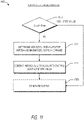
- a method of determining whether a medical instrument is in contact with a target region based, at least in part, on electrical measurements (for example, impedance measurements), which may comprise applying signals having a first frequency and a second frequency to a pair of electrodes or electrode portions of the medical instrument, processing a resulting waveform to obtain impedance measurements at the first frequency and the second frequency, and determining a ratio between the magnitude of the impedance at the second frequency and the first frequency. If the determined ratio is below a predetermined threshold indicative of contact, the method comprises generating a first output indicative of contact. If the determined ratio is above the predetermined threshold, the method comprises generating a second output indicative of no contact. The method may further comprise applying a signal adapted to cause ablative energy to be delivered by the pair of electrodes or electrode portions sufficient to ablate the target region (for example, cardiac tissue or other body tissue).
- electrical measurements for example, impedance measurements
- a system for determining a contact state of a distal end portion of a medical instrument with a target region (for example, tissue) based, at least in part, on electrical measurements comprises a signal source configured to generate at least one signal having a first frequency and a second frequency to be applied to a pair of electrode members of a combination electrode assembly.
- the signal source may be a component of a contact sensing or detection subsystem or an energy delivery module, such as a radiofrequency generator.
- the system also comprises a processor or other computing device configured to, upon execution of specific program instructions stored in memory or a non-transitory computer-readable storage medium, cause the signal source to generate and apply the at least one signal to the pair of electrode members.
- the signal may be a single multi-tone waveform or signal or multiple waveforms or signals having a single frequency.
- the processor may be configured to process a resulting waveform that formulates across the pair of electrode members to obtain a first electrical measurement at the first frequency and to process the resulting waveform that formulates across the pair of electrode members to obtain a second electrical measurement at the second frequency of the plurality of frequencies.
- the processor is further configured to: determine an impedance magnitude based on the first electrical measurement (for example, voltage and/or current measurement), determine an impedance magnitude and a phase based on the second electrical measurement, and calculate a contact indication value indicative of a state of contact between the distal end portion of the medical instrument and the target region based on a criterion combining the impedance magnitude based on the first electrical measurement, a ratio of the impedance magnitudes based on the first electrical measurement and the second electrical measurement, and the phase based on the second electrical measurement.
- the first and second electrical measurements may comprise voltage and/or current measurements or direct impedance measurements between the pair of electrode members.
- the first and second electrical measurements do not comprise direct measurements of electrical parameters or a degree of coupling between an electrode and tissue but are measurements between two electrode members.
- Impedance measurements may be calculated based on the voltage and/or current measurements or may be directly obtained or measured by an instrument or device configured to output impedance measurements.
- the impedance measurements may comprise complex impedance measurements composed of real and imaginary components (for example, impedance magnitude and phase angle measurements or resistance and reactance measurements).
- the impedance measurements comprise bipolar contact impedance measurements between the two electrode members.
- the criterion comprises a weighted combination of the impedance magnitude based on the first electrical measurement, a ratio of the impedance magnitudes based on the first and second electrical measurements, and the phase based on the second electrical measurement.
- the criterion comprises an if-then case conditional criterion, such as described in connection with FIGS. 11 and 11A .
- only one impedance measurement or calculation for example, only impedance magnitude, only slope between impedance magnitude values, or only phase
- only two types of impedance measurements or calculations are used to determine the contact state.
- a system for determining whether a medical instrument is in contact with a target region (for example, tissue) based, at least in part, on impedance measurements consists essentially of or comprises a signal source configured to generate one or more signals having a first frequency and a second frequency to a pair of electrodes (for example, positioned at a distal end of a medical instrument, catheter or probe) and a processing device configured to execute specific program instructions stored on a non-transitory computer-readable storage medium to process a resulting waveform that formulates across the pair of electrodes to obtain impedance measurements at the first frequency and the second frequency.
- processing device is configured to, upon execution of stored instructions on the computer-readable storage medium, generate a first output indicative of contact. If the impedance magnitude at the first and/or second frequency is below a predetermined threshold indicative of no contact, the processing device is configured to, upon execution of stored instructions on the computer-readable storage medium, generate a second output indicative of no contact.
- Processing the waveforms may comprise obtaining voltage and/or current measurements and calculating impedance measurements based on the voltage and/or current measurements or directly obtaining impedance measurements.
- a method of determining whether a medical instrument is in contact with a target region based, at least in part, on impedance measurements which comprises delivering at least one signal having a first frequency and a second frequency (for example, a multi-tonal waveform) to a pair of electrodes or electrode portions and processing a resulting waveform that formulates across the pair of electrodes to obtain impedance measurements at the first frequency and the second frequency. If the impedance magnitude at the first frequency and/or second frequency is above a predetermined threshold indicative of contact, the method comprises generating a first output indicative of contact.
- a target region for example, tissue
- impedance measurements which comprises delivering at least one signal having a first frequency and a second frequency (for example, a multi-tonal waveform) to a pair of electrodes or electrode portions and processing a resulting waveform that formulates across the pair of electrodes to obtain impedance measurements at the first frequency and the second frequency. If the impedance magnitude at the first frequency and/or second frequency is above a predetermined
- the method comprises generating a second output indicative of no contact.
- the method may further comprise applying a signal adapted to cause ablative energy to be delivered by the pair of electrodes or electrode portions sufficient to ablate or otherwise treat cardiac or other body tissue.
- a method of determining whether a medical instrument is in contact with a target region based, at least in part, on impedance measurements which may comprise applying a signal comprising a multi-tone waveform having a first frequency and a second frequency to a pair of electrodes, processing the resulting waveform to obtain impedance measurements at the first frequency and the second frequency, comparing values of the impedance measurements at the first frequency and the second frequency to a known impedance of blood or a blood and saline mixture (or other known tissue impedance), comparing values of the impedance measurements at the first and second frequency to each other; and generating an output indicative of whether or not the medical instrument is in contact with tissue based on said comparisons.
- the method may further comprise applying a signal adapted to cause ablative energy to be delivered by the pair of electrodes sufficient to ablate or otherwise treat cardiac or other body tissue.
- a system for determining whether a medical instrument is in contact with tissue based, at least in part, on impedance measurements which may comprise a signal source configured to generate a multi-tone waveform or signal having a first frequency and a second frequency to a pair of electrodes (for example, at a distal end of a split-tip electrode catheter); and a processing device.
- a signal source configured to generate a multi-tone waveform or signal having a first frequency and a second frequency to a pair of electrodes (for example, at a distal end of a split-tip electrode catheter); and a processing device.
- the processing device may be configured to, upon execution of stored instructions on a computer-readable storage medium, process the resulting waveform to obtain impedance measurements at the first frequency and the second frequency, compare values of the impedance measurements at the first frequency and the second frequency to a known impedance of blood or a blood and saline mixture, compare values of the impedance measurements at the first and second frequency to each other and/or generate an output indicative of whether or not the medical instrument is in contact with tissue based on said comparisons.
- a method of determining whether a medical instrument comprising a pair of electrodes or electrode portions is in contact with a target region (for example, tissue) based, at least in part, on impedance measurements comprises applying at least one signal having a plurality of frequencies (for example, a multi-tonal waveform) to a pair of electrodes of a medical instrument, and processing a resulting waveform that formulates across the pair of electrodes to obtain impedance measurements at a first frequency and a second frequency of the plurality of frequencies. If a variation of the impedance measurements across the range of frequencies has a model whose parameter values are indicative of contact, the method comprises generating a first output indicative of contact.
- a target region for example, tissue
- impedance measurements comprises applying at least one signal having a plurality of frequencies (for example, a multi-tonal waveform) to a pair of electrodes of a medical instrument, and processing a resulting waveform that formulates across the pair of electrodes to obtain impedance measurements at a first frequency and
- the method comprises generating a second output indicative of no contact.
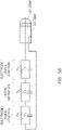
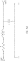
- the model may comprise a fitting function or a circuit model such as shown in FIG. 5B .
- the method may further comprise applying a signal adapted to cause ablative energy to be delivered by the pair of electrodes sufficient to ablate or otherwise treat cardiac or other body tissue.
- a system for determining whether a medical instrument is in contact with tissue based, at least in part, on impedance measurements which comprises a signal source configured to generate at least one signal having a first frequency and a second frequency to a pair of electrodes and a processing device.
- the processing device may be configured to, upon execution of stored instructions on a computer-readable storage medium, apply at least one signal having a plurality of frequencies to a pair of electrodes of a medical instrument and process a resulting waveform that formulates across the pair of electrodes to obtain impedance measurements at a first frequency and a second frequency of the plurality of frequencies.
- Processing the waveforms to obtain impedance measurements may comprise obtaining voltage and/or current measurements and calculating impedance measurements based on the voltage and/or current measurements or directly obtaining impedance measurements.
- a method of determining whether tissue has been ablated by an ablation catheter comprising a pair of electrodes comprises applying one or more signals having a first frequency and a second frequency (for example, a multi-tonal waveform) to a pair of electrodes along the ablation catheter and processing a resulting waveform that formulates across the pair of electrodes to obtain impedance measurements at the first frequency and the second frequency.
- the method may comprise assessing absolute change in the impedance as well as the slope or ratio between impedance.
- the method comprises generating a first output indicative of ablated tissue. If the first impedance measurement at the first and/or second frequency is greater than a known impedance level of blood and if a ratio of the second impedance measurement to the first impedance measurement is above a predetermined threshold, the method comprises generating a second output indicative of viable tissue. Processing the waveforms to obtain impedance measurements may comprise obtaining voltage and/or current measurements and calculating impedance measurements based on the voltage and/or current measurements or directly obtaining impedance measurements. The method may further comprise applying a signal adapted to cause ablative energy to be delivered by the pair of electrodes sufficient to ablate or otherwise treat cardiac or other body tissue.
- a phase of the impedance measurements at the first frequency and/or second frequency is compared to a known phase response for blood or a blood and saline mixture and utilized in conjunction with the magnitude values of the impedance measurements to generate an output indicative of whether or not the medical instrument is in contact with tissue.
- a system for determining whether tissue has been ablated by an ablation catheter comprising a pair of electrodes or electrode portions may comprise a signal source configured to generate at least one signal having a first frequency and a second frequency to a pair of electrodes along the ablation catheter and a processing device.
- the processing device may be configured to, upon execution of stored instructions on a computer-readable storage medium, process a resulting waveform that formulates across the pair of electrodes to obtain impedance measurements at the first frequency and the second frequency. If the first impedance measurement at the first and/or second frequency is greater than a known impedance level of blood and if a ratio of the second impedance measurement to the first impedance measurement is above a predetermined threshold, the processing device is configured to generate a first output indicative of ablated tissue. If a ratio of the second impedance measurement to the first impedance measurement is below a predetermined threshold, the processor is configured to generate a second output indicative of viable (for example, unablated) tissue. Processing the waveforms to obtain impedance measurements may comprise obtaining voltage and/or current measurements and calculating impedance measurements based on the voltage and/or current measurements or directly obtaining impedance measurements.
- Processing the resulting waveform may comprise applying a transform (for example, a Fourier transform) to the waveform to obtain the impedance measurements.
- a transform for example, a Fourier transform
- the first frequency and the second frequency are within a range between 5 kHz and 1000 kHz.
- the second frequency is higher than the first frequency.
- the impedance measurements may be obtained simultaneously or sequentially.
- the second frequency may be at least 20 kHz higher than the first frequency.
- the first frequency is between 10 kHz and 100 kHz (for example, between 10 KHz and 30 kHz, between 15 kHz and 40 kHz, between 20 kHz and 50 kHz, between 30 kHz and 60 kHz, between 40 kHz and 80 kHz, between 50 kHz and 90 kHz, between 60 kHz and 100 kHz, overlapping ranges thereof, 20 kHz or any values from 10 kHz and 100 kHz) and the second frequency is between 400 kHz and 1000 kHz (for example, between 400 kHz and 600 kHz, between 450 kHz and 750 kHz, between 500 kHz and 800 kHz, between 600 kHz and 850 kHz, between 700 kHz and 900 kHz, between 800 kHz and 1000 kHz, overlapping ranges thereof, 800 kHz, or any values from 400 kHz to 1000 kHz).
- the second frequency is between 400 kHz and 1000 kHz (for example, between 400
- the predetermined threshold may have a value between 0.5 and 0.9.
- generating a first output and generating a second output further comprises causing the first output or the second output to be displayed on a display (for example via one or more display drivers).
- the output may comprise textual information, quantitative measurements and/or qualitative assessments indicative of contact state.
- the output includes an amount of contact force corresponding to the level of contact (for example, grams of force).
- Described herein is a method of determining whether a medical instrument having a pair of electrodes or electrode portions is in contact with a target region (for example, tissue) based, at least in part, on impedance measurements which may comprise obtaining a first impedance measurement at a first frequency within a range of frequencies, obtaining a second impedance measurement at a second frequency within the range of frequencies and obtaining a third impedance measurement at a third frequency within the range of frequencies. If a variation of the impedance measurements across the range of frequencies is above a predetermined threshold indicative of contact, the method comprises generating a first output indicative of contact. If the variation of the impedance measurements across the range of frequencies is below the predetermined threshold, the method comprises generating a second output indicative of no contact.
- the impedance measurements may be calculated based on voltage and/or current measurements or may be directly-measured impedance measurements.
- the range of frequencies may be between 5 kHz and 5 MHz (for example, between 5 kHz and 1000 kHz, between 1 MHz and 3 MHz, between 2.5 MHz and 5 MHz, or overlapping ranges thereof).
- the first frequency is between 10 kHz and 100 kHz (for example, between 10 KHz and 30 kHz, between 15 kHz and 40 kHz, between 20 kHz and 50 kHz, between 30 kHz and 60 kHz, between 40 kHz and 80 kHz, between 50 kHz and 90 kHz, between 60 kHz and 100 kHz, overlapping ranges thereof, 20 kHz or any values from 10 kHz and 100 kHz) and the second frequency is between 400 kHz and 1000 kHz (for example, between 400 kHz and 600 kHz, between 450 kHz and 750 kHz, between 500 kHz and 800 kHz, between 600 kHz and 850 kHz, between 700 kHz and 900 kHz,
- the predetermined threshold may be a value between 0.5 and 0.9.
- generating a first output and generating a second output comprises causing the first output or the second output to be displayed on a display.
- the output may comprise textual information indicative of contact.
- the output comprises a quantitative measurement and/or qualitative assessment of contact.
- the method may further comprise applying a signal adapted to cause ablative energy to be delivered by the pair of electrodes or electrode portions sufficient to ablate or otherwise treat cardiac or other body tissue.
- a medical treatment system comprises a medical instrument comprising a proximal end portion, a distal end portion and an elongate body extending from the proximal end portion to the distal end portion.
- the proximal end portion comprises a handle configured to be gripped by a hand of an operator.
- the handle comprises an external steering actuator that is manually operable by the operator, a sensor configured to sense movement of the steering actuator, a tactile stimulation element configured to provide tactile stimulation to the handle, and an internal steering actuation member configured to effect steering of the distal end portion of the medical instrument based on movement of the external steering actuator.
- the system also comprises a control unit configured to receive signals from the sensor indicative of movement of the external steering actuator by the operator and to output signals to actuate a tactile stimulation element and the internal steering actuation member in response to the received signals from the sensor so as to generate the opposition force and so as to effect the steering of the distal end portion.
- the medical instrument comprises an ablation catheter.
- the external steering actuator may comprise a rotatable mechanism, such as a knob, or a push-pull mechanism, such as a plunger or sliding bar. Other mechanisms may also be used to actuate steering as desired and/or required.
- the distal end portion of the medical instrument may comprise a steering plate, the handle may comprise a steering capstan, and steering wires may extend from the steering capstan to the steering plate to effect the steering of the distal end portion.
- the internal steering actuation member comprises a first motor (for example, power steering motor) coupled to the steering capstan and configured to cause rotation of the steering capstan based on the signals received from the sensor.
- the control unit comprises a first motor driver configured to actuate the power steering motor.
- Other steering members other than a plate and capstan may be substituted as desired and/or required.
- the tactile stimulation element comprises a second motor (for example, opposition force motor).
- the control unit may comprise a second motor driver configured to actuate the opposition force motor to provide the opposition force (or other haptic output or feedback) to the handle.
- the distal end portion of the medical instrument comprises a high-resolution electrode assembly comprising a first electrode portion and second electrode portion spaced apart and insulated from the first electrode portion (for example, a split-tip electrode assembly or combination radiofrequency electrode).
- the control unit may comprise a contact detection subsystem or module configured to receive signals from the high-resolution electrode assembly and the control unit (for example, processor) of the contact detection subsystem or module or a separate processor may be configured (for example, specifically programmed with instructions stored in or on a non-transitory computer-readable medium) to determine a level of contact or a contact state with tissue (for example, cardiac tissue) based on the received signals from the high-resolution electrode assembly and to modulate the opposition force provided by the opposition force motor based, at least in part, on the determined level of contact, or the contact state.
- the control unit may further comprise a power delivery module configured to apply radiofrequency power to the high-resolution electrode assembly at a level sufficient to effect ablation of tissue in contact with at least a portion of the distal end
- control unit for example, processor
- the control unit is configured to generate output indicative of the level of contact for display on a display coupled to the control unit (for example, via one or more display drivers).
- the output is based on a contact function determined based on one or more criteria combining multiple electrical parameter measurements (such as voltage measurements, current measurements or impedance measurements).
- the contact function is determined by summing a weighted combination of impedance (for example, bipolar impedance) measurements that are directly measured or that are calculated based on voltage and/or current measurements.
- the contact function is based on one or more if-then case conditional criteria.
- the impedance measurements comprise one or more of an impedance magnitude determined by the contact detection subsystem at a first frequency, a ratio of impedance magnitudes at the first frequency and a second frequency and a phase of a complex impedance measurement at the second frequency.
- the second frequency may be higher than the first frequency (for example, at least 20 kHz higher than the first frequency). In some embodiments, the first frequency and the second frequency are between 5 kHz and 1000 kHz.
- the first frequency is between 10 kHz and 100 kHz (for example, between 10 KHz and 30 kHz, between 15 kHz and 40 kHz, between 20 kHz and 50 kHz, between 30 kHz and 60 kHz, between 40 kHz and 80 kHz, between 50 kHz and 90 kHz, between 60 kHz and 100 kHz, overlapping ranges thereof, 20 kHz or any values from 10 kHz and 100 kHz) and the second frequency is between 400 kHz and 1000 kHz (for example, between 400 kHz and 600 kHz, between 450 kHz and 750 kHz, between 500 kHz and 800 kHz, between 600 kHz and 850 kHz, between 700 kHz and 900 kHz, between 800 kHz and 1000 kHz, overlapping ranges thereof, 800 kHz, or any values from 400 kHz to 1000 kHz); however, other frequencies may be used as desired and/or required. In some embodiments, other frequencies may
- the handle of the medical instrument further comprises a motion detection element (for example, at least one of an accelerometer and a gyroscope).
- the first motor is configured to be actuated only when the motion detection element is detecting motion of the handle.
- a method of determining a contact state of a distal end portion of a medical instrument with a target region, for example, tissue comprises applying at least one signal having a plurality of frequencies to a pair of electrodes or electrode portions of a combination electrode assembly positioned along a distal end portion of a medical instrument.
- the method comprises processing a resulting waveform that formulates across the pair of electrodes to obtain a first impedance measurement at a first frequency of the plurality of frequencies and processing the resulting waveform that formulates across the pair of electrodes to obtain a second impedance measurement at a second frequency of the plurality of frequencies.
- the method further comprises determining a magnitude of the first impedance measurement, determining a magnitude and a phase of the second impedance measurement and applying a contact function (for example, via execution of a computer program stored on a non-transitory computer storage medium) to calculate a contact indication value indicative of a state of contact between the distal end portion of the medical instrument and the target region (for example, cardiac tissue).
- the contact function may be determined by summing a weighted combination of the magnitude of the first impedance measurement, a ratio of the magnitudes of the first impedance measurement and the second impedance measurement, and the phase of the second impedance measurement.
- the first frequency and the second frequency are different.
- the second frequency is higher than the first frequency.
- the method may further comprise generating output corresponding to the contact indication value for display on a display monitor (for example, via one or more display drivers).
- the output comprises a qualitative and/or a quantitative output.
- the output may comprise a numerical value between 0 and 1 or between 0 and 1.5, with values above 1 indicating excessive contact.
- the output comprises a percentage value or a number corresponding to an amount of contact force (for example, grams of contact force).
- the output may comprise a color and/or pattern indicative of the contact state and/or one or more of a gauge, a bar, or a scale.
- the output comprises a haptic or other tactile output.
- the method may further comprise applying a signal adapted to cause ablative energy to be delivered by the pair of electrodes or electrode portions sufficient to ablate or otherwise treat cardiac or other body tissue.
- a system for determining a contact state of a distal end portion of a medical instrument with a target region consists essentially of or comprises a signal source configured to generate at least one signal having a first frequency and a second frequency to be applied to a pair of electrode members of a combination electrode assembly (for example, two electrode members separated by a gap).
- the system also consists essentially of or comprises a processing device configured to (a) cause the signal source to generate and apply the at least one signal to the pair of electrode members, (b) process a resulting waveform that formulates across the pair of electrode members to obtain a first electrical measurement at the first frequency, (c) process the resulting waveform that formulates across the pair of electrode members to obtain a second electrical measurement at the second frequency of the plurality of frequencies, (d) determine an impedance magnitude based on the first electrical measurement, (e) determine an impedance magnitude and a phase based on the second electrical measurement, and (f) calculate a contact indication value indicative of a state of contact between the distal end portion of the medical instrument and the target region based on a criterion combining the impedance magnitude based on the first electrical measurement, a ratio of the impedance magnitudes based on the first and second electrical measurements, and the phase based on the second electrical measurement.
- a processing device configured to (a) cause the signal source to generate and apply the at least one signal
- the electrical measurements may comprise voltage, current, and/or other electrical parameter measurements from which impedance measurements (such as impedance magnitude or phase) may be calculated or may comprise directly-obtained impedance measurements.
- the criterion may comprise a weighted combination of the impedance magnitude based on the first electrical measurement, a ratio of the impedance magnitudes based on the first and second electrical measurements, and the phase based on the second electrical measurement or the criterion may comprise an if-then case conditional criterion.
- the system further comprises the medical instrument, which may be a radiofrequency ablation catheter.
- the first frequency and the second frequency may be different.
- the second frequency is higher than the first frequency.
- the second frequency is lower than the first frequency.
- the first frequency and the second frequency are between 5 kHz and 1000 kHz (for example, between 5 kHz and 50 kHz, between 10 kHz and 100 kHz, between 50 kHz and 200 kHz, between 100 kHz and 500 kHz, between 200 kHz and 800 kHz, between 400 kHz and 1000 kHz, or overlapping ranges thereof).
- the two frequencies are at least 20 kHz apart in frequency.
- the processor is further configured to generate output corresponding to the contact indication value for display on a display monitor, upon execution of specific instructions stored in or on a computer-readable medium.
- the output comprises a numerical value between 0 and 1.
- the output comprises a qualitative output (such as a color and/or pattern indicative of the contact state).
- the output comprises one or more of a gauge, a bar, a meter or a scale.
- the output comprises a virtual gauge having a plurality of regions (for example, two, three, four, five or more than five regions or segments) indicative of varying levels of contact, or contact states. The plurality of regions may be represented in different colors. Each of the plurality of regions may correspond to a different range of numerical values indicative of varying levels of contact.
- the output comprises a haptic, or tactile, output.
- a system for displaying a contact state of a distal tip of a medical instrument with a target region (for example, body tissue) on a patient monitor comprises a processor configured to generate output for display on the patient monitor.
- the output may be generated on a graphical user interface on the patient monitor.
- the output comprises a graph that displays a contact function indicative of a contact state between a distal tip of a medical instrument and body tissue calculated by a processing device based, at least in part, on impedance measurements obtained by the medical instrument.
- the graph may be a scrolling waveform.
- the output also comprises a gauge separate from the graph that indicates a real-time state of contact corresponding to a real-time numerical value of the contact function displayed by the graph.
- the gauge includes a plurality of regions indicative of varying contact states. In some embodiments, each one of the plurality of regions is optionally displayed in a different color or graduation to provide a qualitative indication of the real-time state of contact.
- the gauge consists of three regions or segments. The three regions may be colored red, yellow and green. In another embodiment, the gauge consists of four regions or segments. The four regions may be colored red, orange, yellow and green. Each of the plurality of regions may correspond to a different range of numerical values indicative of the current contact state.
- the gauge may comprise a pointer that indicates a level on the gauge corresponding to the real-time numerical value of the contact function.
- the real-time numerical value may range between 0 and 1 or between 0 and 1.25 or between 0 and 1.5. Values above 1 may generate a "contact alert" to the clinician to prevent excessive contact, which could result in perforation of tissue.
- the gauge may comprise a contact indicator of the quality of tissue-electrode contact calculated based on bipolar impedance magnitude, bipolar impedance-frequency slope and bipolar impedance phase.
- the output may also comprise other graphs or waveforms of individual components of impedance measurements (for example, impedance magnitude and phase) at multiple frequencies or of comparisons (for example, a slope) between two impedance measurements (for example, impedance magnitude at two different frequencies).
- the contact function is calculated based on a weighted combination of a magnitude of a first impedance measurement at a first frequency, a ratio of the magnitudes of the first impedance measurement and a second impedance measurement at a second frequency different from the first frequency, and the phase of the second impedance measurement at the second frequency.
- the second frequency is higher than the first frequency.
- the second frequency is lower than the first frequency.
- the first frequency and the second frequency may be between 5 kHz and 1000 kHz.
- the system further comprises the patient monitor.
- a system for assessing a level of contact between a distal end portion of an ablation catheter having a pair of spaced-apart electrode members of a combination electrode assembly and target region, e.g., tissue comprises a signal source configured to generate signals having at least a first frequency and a second frequency to be applied to the pair of spaced-apart electrode members.
- the system also comprises a processor configured to, upon execution of specific program instructions stored on a computer-readable storage medium, measure network parameters at an input of a network measurement circuit comprising a plurality of hardware components between the signal source and the pair of spaced-apart electrode members.
- the processor may also be configured (for example, specifically programmed, constructed or designed) to determine an aggregate effect on a measured network parameter value caused by the hardware components of the network measurement circuit, remove the aggregate effect to result in a corrected network parameter value between the pair of spaced-apart electrode members, and determine a level of contact based, at least in part, on the corrected network parameter value.
- the processor is configured to generate an output indicative of the level of contact for display.
- the signal source may be located within a radiofrequency generator or within the ablation catheter.
- the processor may be configured to measure network parameters at at least two frequencies (for example, two frequencies, three frequencies, four frequencies or more than four frequencies). In some embodiments, the frequencies are between 5 kHz and 1000 kHz. In embodiments involving two frequencies, the second frequency may be at least 20 kHz higher than the first frequency. For example, the first frequency may be between 10 kHz and 100 kHz and the second frequency is between 400 kHz and 1000 kHz.
- a third frequency may be higher than the first frequency and lower than the second frequency (for example, the third frequency may be between 20 kHz and 120 kHz.).
- the network parameters may comprise scattering parameters or other electrical parameters (such as voltage, current, impedance).
- the network parameter values may comprise, for example, voltage and current values or impedance values either directly measured or determined from voltage and/or current values.
- Impedance values may comprise impedance magnitude values and impedance phase values or resistance and reactance values.
- the impedance magnitude values may be obtained at two or more frequencies and slopes may be determined between magnitude values at different frequencies.
- the impedance phase values may be obtained at one or more frequencies.
- a method of assessing a level of contact determination of a distal end portion of an ablation catheter having a pair of spaced-apart electrode members comprises measuring network parameters at an input of a network parameter circuit of hardware components between a signal source and the pair of spaced-apart electrode members. The method also comprises determining an aggregate effect on a measured network parameter value determined from the network parameters caused by the hardware components, removing the aggregate effect to result in a corrected network parameter value between the pair of spaced-apart electrode members, and determining a level of contact based, at least in part, on the corrected network parameter value.
- Measuring network parameters may comprise measuring network parameters at a plurality of frequencies. In some embodiments, determining an aggregate effect on the measured network parameter value caused by the hardware components of the network parameter circuit comprises measuring network parameters associated with each individual hardware component. In some embodiments, determining an aggregate effect on the measured network parameter value caused by the hardware components of the network parameter circuit comprises combining the network parameters of the individual hardware components into total network parameters at a plurality of frequencies. Removing the aggregate effect so as to isolate an actual network parameter value between the pair of spaced-apart electrode members may comprise de-embedding the total network parameters from a measured input reflection coefficient to result in an actual reflection coefficient corresponding to the actual network parameter value. In some embodiments, the method is performed automatically by a processor. The method may further comprise applying a signal adapted to cause ablative energy to be delivered by the pair of spaced-apart electrode members sufficient to ablate or otherwise treat cardiac or other body tissue.
- a system comprises a signal source (for example, a source of radiofrequency energy or excitation signals) configured to deliver signals having at least a first frequency and a second frequency to a pair of electrode members of a combination electrode assembly (for example, spaced-apart bipolar pair of electrode members) positioned along a distal end portion of a medical instrument (for example, radiofrequency ablation catheter).
- a signal source for example, a source of radiofrequency energy or excitation signals
- a pair of electrode members of a combination electrode assembly for example, spaced-apart bipolar pair of electrode members
- a medical instrument for example, radiofrequency ablation catheter
- the embodiment of the system also comprises a processing device (for example, specific-purpose processor) configured to, upon execution of specific program instructions stored on a computer-readable storage medium: cause the signal source to generate and apply the signals to the pair of electrode members, obtain electrical measurements (for example, bipolar contact impedance measurements that are directly measured or that are calculated or otherwise determined from voltage and/or current measurements) between the pair of electrode members while signals having at least the first frequency and the second frequency are being applied to the pair of electrode members, process the electrical measurements obtained at the first frequency and the second frequency, and determine whether the combination electrode assembly is in contact with tissue based on said processing of the electrical measurements.
- the processing device is configured to generate an output indicative of contact.
- the output may comprise any type of output described herein (for example, visual, audible, and/or tactile) and may be output on a display in communication with the processing device.
- the embodiment of the system may comprise a contact sensing subsystem including the signal source and the processing device.
- the system may also comprise an ablative energy source configured to generate and apply power to the combination electrode assembly for ablating the target region, as described herein.
- the processing device may be configured (for example, specifically programmed) to adjust one or more energy delivery parameters of the ablative energy based on a determination of whether the combination electrode assembly is in contact with tissue and/or to terminate energy delivery based on a determination of whether the combination electrode assembly is in contact with tissue.
- the ablative energy source and the signal source comprise a single source.
- the signal source comprises a first source and the ablative energy source comprises a second source that is separate and distinct from the first source.
- the contact sensing subsystem is located within the energy delivery device. In some embodiments where the signal source and the ablative energy source are separate sources, the contact sensing subsystem is located within a housing that also houses the ablative energy source.
- the embodiment of the system optionally comprises the medical instrument itself.
- the medical instrument may consist essentially of or comprise an ablation catheter comprising an elongate body having a proximal end and a distal end and wherein the energy delivery device comprises the combination electrode assembly.
- the combination electrode assembly includes a first electrode member positioned along the elongate body (for example, at a distal terminus) and a second electrode member positioned adjacent the first electrode member (for example, spaced apart by a gap sufficient to electrically insulate the two electrode members).
- the two electrode members may be positioned, shaped, sized and/ or designed (for example, configured) to contact tissue of a subject.
- the combination electrode assembly also includes an electrically insulating gap positioned between the first electrode member and the second electrode member, the electrically insulating gap comprising a gap width separating the first and second electrode members.
- the processing device of the system is configured to determine an impedance magnitude value based on a first electrical measurement obtained from the signal at the first frequency and to determine an impedance magnitude value and an impedance phase angle value based on a second electrical measurement obtained from the signal at the second frequency.
- the processing device is configured to calculate a contact indication value indicative of a state of contact between the distal end portion of the medical instrument and the target region based on a criterion combining the impedance magnitude value based on the first electrical measurement, a ratio of the impedance magnitude values based on the first electrical measurement and the second electrical measurement, and the impedance phase based on the second electrical measurement.
- the criterion may comprise a weighted combination of the impedance magnitude based on the first electrical measurement, a ratio of the impedance magnitude values based on the first and second electrical measurements, and the impedance phase value based on the second electrical measurement or the criterion may comprise an if-then conditional criterion.
- the signals generated and applied to the pair of electrode members do not travel to a patch electrode remote from the target region so as to facilitate bipolar contact measurements between the two electrode members.
- the processing device of the embodiment of the system may be configured to measure network parameters at an input of a network measurement circuit comprising a plurality of hardware components between the signal source and the pair of electrode members, determine an aggregate effect on a measured network parameter value caused by the hardware components of the network measurement circuit, remove the aggregate effect to result in a corrected network parameter value between the pair of electrode members, and determine a level of contact between the pair of electrode members and tissue based, at least in part, on the corrected network parameter value.
- the first applied frequency may be between 10 kHz and 100 kHz and the second applied frequency may be between 400 kHz and 1000 kHz.
- the signal source is further configured to generate a signal having a third frequency to be applied to the pair of spaced-apart electrode members and the processing device is further configured to measure network parameters at the third frequency.
- the third frequency is higher than the first frequency and lower than the second frequency. In various embodiments, the third frequency is between 20 kHz and 120 kHz.
- the network parameters may be scattering parameters or impedance parameters.
- the network parameter values may be impedance values comprised of bipolar impedance magnitude values, bipolar impedance phase values and/or bipolar slope values between impedance magnitude values at different frequencies.
- a kit comprises a radiofrequency generator comprising an ablative energy source, an ablation catheter comprising a pair of electrode members separated by a gap positioned along a distal end portion of the ablation catheter; and a contact sensing subsystem comprising a signal source configured to generate and apply signals having at least two different frequencies to the pair of electrode members and a processor configured to determine a level of contact between the pair of electrode members and target tissue based, at least in part, on electrical measurements between the pair of electrode members while the signals having the at least two different frequencies are being applied.
- the contact sensing subsystem of the kit may be housed within the radiofrequency generator or may be a separate component from the radiofrequency generator.
- the kit may optionally comprise electrical cables for connecting the ablation catheter to the radiofrequency generator and/or for connecting the ablation catheter to the contact sensing subsystem.
- the radiofrequency generator may include an integrated display and the contact sensing subsystem may be configured to generate an output indicative of the level of contact to the display.
- the processing device may be configured to perform operations recited herein upon execution of instructions stored within memory or a non-transitory storage medium.
- the methods summarized above and set forth in further detail below may describe certain actions taken by a practitioner; however, it should be understood that they can also include the instruction of those actions by another party. For example, actions such as “terminating energy delivery” include “instructing the terminating of energy delivery.” Further aspects of embodiments of the disclosure will be discussed in the following portions of the specification. With respect to the drawings, elements from one figure may be combined with elements from the other figures.
- an ablation or other energy delivery system can comprise a high-resolution, or combination electrode, design, wherein the energy delivery member (for example, radiofrequency electrode, laser electrode, microwave transmitting electrode) comprises two or more separate electrodes or electrode members or portions.
- the energy delivery member for example, radiofrequency electrode, laser electrode, microwave transmitting electrode
- such separate electrodes or electrode portions can be advantageously electrically coupled to each other (for example, to collectively create the desired heating or ablation of targeted tissue).
- the combination electrode, or split-tip, design may be leveraged to determine whether or not one or more portions of the electrodes or other energy delivery members are in contact with tissue (for example, endocardial tissue) and/or whether or not contacted tissue has been ablated (for example, to determine whether the tissue is viable or not).
- tissue for example, endocardial tissue
- ablated tissue for example, to determine whether the tissue is viable or not.
- high-resolution electrodes or combination electrodes are defined as any electrode(s) capable of delivering ablative or other energy to tissue capable of transferring heat to/from such tissue, while being capable of obtaining accurate mapping data of adjacent tissue, and include, without limitation, split-tip RF electrodes, other closely oriented electrodes or electrode portions and/or the like.
- Several embodiments of the disclosure are particularly advantageous because they include one, several or all of the following benefits: (i) confirmation of actual tissue contact that is easily ascertainable; (ii) confirmation of contact with ablated vs. unablated (viable) tissue that is easily ascertainable; (iii) low cost, as the disclosure does not require any specialized sensor; (iv) does not require use of radiometry; (v) provides multiple forms of output or feedback to a user; (vi) provides output to a user without requiring the user to be watching a display; (vii) reduction in proximal edge heating and reduced likelihood of char formation; (viii) does not require use of remote patch electrode(s) for tissue contact sensing or detection; and/or (ix) provides safer and more reliable ablation procedures.
- FIG. 1 schematically illustrates one embodiment of a treatment system 10 that is configured to selectively ablate, stimulate, modulate and/or otherwise heat or treat targeted tissue (for example, cardiac tissue, pulmonary vein, other vessels or organs, etc.).
- targeted tissue for example, cardiac tissue, pulmonary vein, other vessels or organs, etc.
- the system 10 can include a medical instrument 20 (for example, catheter) comprising one or more energy delivery members 30 (for example, radiofrequency electrodes) along a distal end of the medical instrument 20.
- the medical instrument can be sized, shaped and/or otherwise configured to be passed intraluminally (for example, intravascularly) through a subject being treated.
- the medical instrument 20 comprises a catheter, a shaft, a wire, and/or other elongate instrument configured for examination, diagnosis, imaging and/or treatment, such as tissue ablation.
- the medical instrument 20 is not positioned intravascularly but is positioned extravascularly via laparoscopic or open surgical procedures.
- the medical instrument 20 comprises a catheter, a shaft, a wire, and/or other elongate instrument.
- one or more temperature-measurement devices or systems 60 may be included at the distal end of the medical instrument 20, or along its elongate shaft or in its handle.
- the term "distal end” does not necessarily mean the distal terminus or distal end. Distal end could mean the distal terminus or a location spaced from the distal terminus but generally at a distal end portion of the medical instrument 20.
- the medical instrument 20 may optionally include mapping electrodes.
- the medical instrument 20 is operatively coupled to one or more devices or components.
- the medical instrument 20 can be coupled to a delivery module 40 (such as an energy delivery module).
- the delivery module 40 includes an energy generation device 42 that is configured to selectively energize and/or otherwise activate the energy delivery member(s) 30 (for example, radiofrequency electrode(s)) located along the medical instrument20.
- the energy generation device 42 comprises one or more signal sources, such as a radiofrequency generator, an ultrasound energy source, a microwave energy source, a laser/light source, anothertype of energy source or generator, and the like, and combinations thereof.
- energy generation device 42 is substituted with or used in addition to a source of fluid, such as cryogenic fluid or other fluid that modulates temperature.
- a source of fluid such as cryogenic fluid or other fluid that modulates temperature.
- the delivery module for example, delivery module 40
- delivery module 40 can also be a cryogenic device or other device that is configured for thermal modulation.
- the energy delivery module 40 can include one or more input/output devices or components 44, such as, for example, a touchscreen device, a screen or other display, a controller (for example, button, knob, switch, dial, etc.), keypad, keyboard, mouse, joystick, trackpad, or other input device and/or the like. Such devices can permit a physician or other user to enter information into and/or receive information from the system 10.
- the output device 44 can include a display monitor or other display that provides tissue temperature information, contact information, other measurement information and/or other data or indicators that can be useful for regulating a particular treatment procedure (for example, on one or more graphical user interfaces generated by the processor 46).
- the input/output devices or components 44 may include an electrophysiology monitor and/or mapping or navigation systems.
- the input devices or components are integrated into the output devices or components.
- a touchscreen input interface or input keypads or knobs or switches may be integrated into a display monitor or the energy delivery module 40 (for example, generator or control unit).
- the output devices include haptic devices to facilitate haptic feedback.
- the delivery module 40 includes a processor 46 (for example, a processing or control device) that is configured to regulate one or more aspects of the treatment system 10.
- the delivery module 40 can also comprise a memory unit or other storage device 48 (for example, non-transitory computer readable medium) that can be used to store operational parameters and/or other data related to the operation of the system 10.
- the processor 46 comprises or is in communication with a contact sensing and/or a tissue type detection module or subsystem.
- the contact sensing subsystem or module may be adapted to determine whether or not the energy delivery member(s) 30 of the medical instrument 20 are in contact with tissue (for example, contact sufficient to provide effective energy delivery).
- the tissue type detection module or subsystem may be adapted to determine whether the tissue in contact with the one or more energy delivery member(s) 30 has been ablated or otherwise treated.
- the system 10 comprises a contact sensing subsystem 50.
- the contact sensing subsystem 50 may be communicatively coupled to the processor 46 and/or comprises a separate controller or processor and memory or other storage media.
- the contact sensing subsystem 50 may perform both contact sensing and tissue type determination functions.
- the contact sensing subsystem 50 may be a discrete, standalone sub-component of the system (as shown schematically in FIG. 1 ) or may be integrated into the energy delivery module 40 or the medical instrument 20. Additional details regarding a contact sensing subsystem are provided below.
- the processor 46 is adapted to automatically regulate the delivery of energy from the energy generation device 42 to the energy delivery member 30 of the medical instrument 20 based on one or more operational schemes. For example, energy provided to the energy delivery member 30 (and thus, the amount of heat transferred to or from the targeted tissue) can be regulated based on, among other things, the detected temperature of the tissue being treated, whether the tissue is determined to have been ablated, or whether the energy delivery member 30 is determined to be in contact (for example, "sufficient" contact, or contact above a threshold level) with the tissue to be treated.
- the treatment system 10 can include one or more temperature detection devices, such as, for example, reference temperature devices (for example, thermocouples, thermistors, radiometers, etc.), tissue temperature measurement devices (for example, thermocouples, thermistors, radiometers, etc.) and/or the like.
- the temperature-measurement devices, systems and/or other components of the system can be configured to help determine (for example, detect) a peak (for example, high or peak, low or trough, etc.) temperature of tissue at a depth (for example, relative to a tissue surface), to detect orientation of a treatment or monitoring portion of a medical instrument (for example, a distal end portion of a catheter comprising a high-resolution electrode assembly).
- the temperature measurement devices located at, along and/or near an ablation member (e.g., RF electrode) can help with the determination of whether contact is being made between the ablation member and targeted tissue (and/or to what degree such contact is being made). In some embodiments, such peak temperature is determined without the use of radiometry.
- the medical instruments for example, catheters described herein may incorporate any of the features or components (such as multiple groups of temperature-measurement devices spaced apart axially along a length and/or circumferentially) of the medical instruments (for example, ablation catheters).
- a first group of temperature-measurement devices are positioned along a distal electrode member of a combination electrode assembly and a second group of temperature-measurement devices are positioned along or adjacent a proximal electrode member of the combination electrode assembly.
- the temperature-measurement devices may be thermally insulated from the electrode members such that the temperature-measurement devices do not measure the temperature of the electrode members themselves.
- the treatment system 10 comprises (or is adapted to be placed in fluid communication with) an irrigation fluid system 70.
- an irrigation fluid system 70 is at least partially separate from the delivery module 40 and/or other components of the system 10.
- the irrigation fluid system 70 is incorporated, at least partially, into the energy delivery module 40.
- the irrigation fluid system 70 can include one or more pumps or other fluid transfer devices that are configured to selectively move fluid (for example, biocompatible fluid such as saline) through one or more lumens or other passages of the catheter 20.
- fluid can be used to selectively cool (for example, transfer heat away from) the energy delivery member 30 during use.
- the system 10 does not comprise an irrigation fluid system 70.
- FIG. 2A illustrates one embodiment of a distal end of a medical instrument (for example, catheter or other elongate member) 20.
- the medical instrument (for example, catheter) 20 can include a high-resolution, combination electrode (for example, split tip) design, such that there are two adjacent electrodes or two adjacent electrode members or portions 30A, 30B separated by a gap G.
- the relative length of the different electrodes or electrode portions 30A, 30B can vary.
- the length of the proximal electrode 30B can be between 1 to 20 times (for example, 1-2, 2-3, 3-4, 4-5, 5-6, 6-7, 7-8, 8-9, 9-10, 10-11, 11-12, 12-13, 13-14, 14-15, 15-16, 16-17, 17-18, 18-19, 19-20, values between the foregoing ranges, etc.) the length of the distal electrode 30A, as desired or required.
- the length of the proximal electrode 30B can be greater than 20 times (for example, 20-25, 25-30, more than 30 times, etc.) the length of the distal electrode 30A.
- the lengths of the distal and proximal electrodes 30A, 30B are about equal.
- the distal electrode 30A is longer than the proximal electrode 30B (for example, by 1 to 20 times, such as, for example, 1-2, 2-3, 3-4, 4-5, 5-6, 6-7, 7-8, 8-9, 9-10, 10-11, 11-12, 12-13, 13-14, 14-15, 15-16, 16-17, 17-18, 18-19, 19-20, values between the foregoing ranges, etc.).
- the distal electrode or electrode portion 30A is 0.9 mm long. In other embodiments, the distal electrode or electrode portion 30A is between 0.1 mm and 1.5 mm long (for example, 0.1-0.2, 0.2-0.3, 0.3-0.4, 0.4-0.5, 0.5-0.6, 0.6-0.7, 0.7-0.8, 0.8-0.9, 0.9-1.0, 1.0-1.1, 1.1-1.2, 1.2-1.3, 1.3-1.4, 1.4-1.5 mm, values between the foregoing ranges, etc.). In other embodiments, the distal electrode or electrode portion 30A is greater than 1.5 mm in length, as desired or required.
- the proximal electrode or electrode portion 30B is 2 to 4 mm long (for example, 2-2.5, 2.5-3, 3-3.5, 3.5-4 mm, lengths between the foregoing, etc.). However, in other embodiments, the proximal electrode portion 30B is greater than 4 mm (for example, 4-5, 5-6, 6-7, 7-8, 8-9, 9-10 mm, greater than 10 mm, etc.) or smaller than 1 mm (for example, 0.1-0.5 0.5-1, 1-1.5, 1.5-2 mm, lengths between the foregoing ranges, etc.), as desired or required.
- the length of the electrodes can be 1 to 5 mm (for example, 1-2, 2-3, 3-4, 4-5 mm, lengths between the foregoing, etc.).
- the electrodes or portions can be longer than 5 mm (for example, 5-6, 6-7, 7-8, 8-9, 9-10, 10-15, 15-20 mm, lengths between the foregoing, lengths greater than 20 mm, etc.), as desired or required.
- the use of a combination electrode (for example, split tip) design can permit a user to simultaneously ablate or otherwise thermally treat targeted tissue and map (for example, using high-resolution mapping) in a single configuration.
- such systems can advantageously permit precise high-resolution mapping (for example, to confirm that a desired level of treatment occurred) during a procedure.
- the high-resolution design that includes two electrodes or electrode portions 30A, 30B can be used to record a high-resolution bipolar electrogram.
- the two electrodes or electrode portions 30A, 30B can be connected to the inputs of an electrophysiology (EP) recorder.
- a relatively small separation distance (for example, gap G) between the electrodes or electrode portions 30A, 30B enables high-resolution mapping.
- the electrodes or electrode portions 30A, 30B are radiofrequency electrodes and comprise one or more metals, such as, for example, stainless steel, platinum, platinum-iridium, gold, gold-plated alloys and/or the like. According to some embodiments, as illustrated in FIG. 2A , the electrodes or electrode portions 30A, 30B are spaced apart from each other (for example, longitudinally or axially) using a gap (for example, an electrically insulating gap). In some embodiments, the length of the gap G (or the separation distance between adjacent electrodes or electrode portions) is 0.5 mm.
- the gap G or separation distance is greater or smaller than 0.5 mm, such as, for example, 0.1-1 mm (for example, 0.1-0.2, 0.2-0.3, 0.3-0.4, 0.4-0.5, 0.5-0.6, 0.6-0.7, 0.7-0.8, 0.8-0.9, 0.9-1.0 mm, values between the foregoing ranges, less than 0.1 mm, greater than 1 mm, etc.), as desired or required.
- 0.1-1 mm for example, 0.1-0.2, 0.2-0.3, 0.3-0.4, 0.4-0.5, 0.5-0.6, 0.6-0.7, 0.7-0.8, 0.8-0.9, 0.9-1.0 mm, values between the foregoing ranges, less than 0.1 mm, greater than 1 mm, etc.
- a separator 34 is positioned within the gap G, between the adjacent electrodes or electrode portions 30A, 30B, as depicted in FIG. 2A .
- the separator can comprise one or more electrically insulating materials, such as, for example, Teflon, polyetheretherketone (PEEK), polyetherimide resins (for example, ULTEM TM ), diamond (for example, industrial grade diamond), ceramic materials, polyimide and the like.
- the insulating separator 34 can be 0.5 mm long.
- the length of the separator 34 can be greater or smaller than 0.5 mm (for example, 0.1-0.2, 0.2-0.3, 0.3-0.4, 0.4-0.5, 0.5-0.6, 0.6-0.7, 0.7-0.8, 0.8-0.9, 0.9-1.0 mm, values between the foregoing ranges, less than 0.1 mm, greater than 1 mm, etc.), as desired or required.
- the two electrodes or electrode portions 30A, 30B are electrically coupled to each other at the RF treatment (for example, ablation) frequency.
- the two electrodes or electrode portions can advantageously function as a single longer electrode at the RF treatment frequency.
- one of the electrode portions (for example, the distal electrode) 30A can be electrically coupled to an energy delivery module 40 (for example, an RF generator).
- the module 40 can comprise one or more components or features, such as, for example, an energy generation device that is configured to selectively energize and/or otherwise activate the energy members (for example, RF electrodes), one or more input/output devices or components, a processor (for example, a processing or control device) that is configured to regulate one or more aspects of the treatment system, a memory and/or the like.
- an energy generation device that is configured to selectively energize and/or otherwise activate the energy members (for example, RF electrodes)
- a processor for example, a processing or control device
- such a module can be configured to be operated manually or automatically, as desired or required.
- FIGS. 2B and 2C illustrate different embodiments of catheter systems 100, 200 that incorporate a high-resolution tip design.
- the electrode e.g., radiofrequency electrode
- the high-resolution tip design 100 includes a gap G between the first and second electrodes or electrode portions 110, 114.
- the second or proximal electrode or electrode portion 114 is generally longer than the first or distal electrode or electrode portion 110.
- the length of the proximal electrode 114 can be between 1 to 20 times (e.g., 1-2, 2-3, 3-4, 4-5, 5-6, 6-7, 7-8, 8-9, 9-10, 10-11, 11-12, 12-13, 13-14, 14-15, 15-16, 16-17, 17-18, 18-19, 19-20, values between the foregoing ranges, etc.) the length of the distal electrode 110, as desired or required.
- the length of the proximal electrode can be greater than 20 times (e.g., 20-25, 25-30, more than 30 times, etc.) the length of the distal electrode.
- the lengths of the distal and proximal electrodes are about the same.
- the distal electrode 110 is longer than the proximal electrode 114 (e.g., by 1 to 20 times, such as, for example, 1-2, 2-3, 3-4, 4-5, 5-6, 6-7, 7-8, 8-9, 9-10, 10-11, 11-12, 12-13, 13-14, 14-15, 15-16, 16-17, 17-18, 18-19, 19-20, values between the foregoing ranges, etc.).
- the electrodes or electrode portions 110, 114 can be separated by a gap G.
- the gap G can comprise a relatively small electrically insulating gap or space.
- an electrically insulating separator 118 can be snugly positioned between the first and second electrodes or electrode portions 110, 114.
- the separator 118 can have a length of about 0.5 mm.
- the length of the separator 118 can be greater or smaller than 0.5 mm (e.g., 0.1-0.2, 0.2-0.3, 0.3-0.4, 0.4-0.5, 0.5-0.6, 0.6-0.7, 0.7-0.8, 0.8-0.9, 0.9-1.0 mm, values between the foregoing ranges, less than 0.1 mm, greater than 1 mm, etc.), as desired or required.
- 0.5 mm e.g., 0.1-0.2, 0.2-0.3, 0.3-0.4, 0.4-0.5, 0.5-0.6, 0.6-0.7, 0.7-0.8, 0.8-0.9, 0.9-1.0 mm, values between the foregoing ranges, less than 0.1 mm, greater than 1 mm, etc.
- the separator can include one or more electrically insulating materials (e.g., materials that have an electrical conductivity less than about 1000 or less (e.g., 500-600, 600-700, 700-800, 800-900, 900-1000, 1000-1100, 1100-1200, 1200-1300, 1300-1400, 1400-1500, values between the foregoing, less than 500, greater than 1500, etc.) than the electrical conductivity of metals or alloys).
- the separator can comprise one or more electrically insulating materials, such as, for example, Teflon, polyetheretherketone (PEEK), polyoxymethylene, acetal resins or polymers and the like.
- the separator 118 can be cylindrical in shape and can have the identical or similar diameter and configuration as the adjacent electrodes or electrode portions 110, 114.
- the outer surface formed by the electrodes or electrode portions 110, 114 and the separator 118 can be generally uniform or smooth.
- the shape, size (e.g., diameter) and/or other characteristics of the separator 118 can be different than one or more of the adjacent electrodes or electrode portions 110, 114, as desired or required for a particular application or use.
- FIG. 2C illustrates an embodiment of a system 200 having three or more electrodes or electrode portions 210, 212, 214 separated by corresponding gaps G1, G2.
- additional gaps and thus, additional electrodes or electrode portions 210, 212, 214 that are physically separated (e.g., by gaps) yet in close proximity to each other, can provide additional benefits to the high-resolution mapping capabilities of the system.
- the use of two (or more) gaps can provide more accurate high-resolution mapping data related to the tissue being treated.
- Such multiple gaps can provide information about the directionality of cardiac signal propagation.
- high-resolution mapping with high-resolution electrode portions involving multiple gaps can provide a more extended view of lesion progression during the ablation process and higher confidence that viable tissue strands are not left behind within the targeted therapeutic volume.
- high-resolution electrodes with multiple gaps can optimize the ratio of mapped tissue surface to ablated tissue surface. Preferably, such ratio is in the range of 0.2 to 0.8 (e.g., 0.2-0.3, 0.3-0.4, 0.4-.5, 0.5-0.6, 0.6-0.7, 0.7-0.8, ratios between the foregoing, etc.).
- an ablation or other treatment system can include 4 or more (e.g., 5, 6, 7, 8, more than 8, etc.) electrodes or electrode portions (and thus, 3 or more gaps, e.g., 3, 4, 5, 6, 7 gaps, more than 7 gaps, etc.), as desired or required.
- a gap and/or an electrical separator
- FIGS. 2 to 4 illustrate the embodiments illustrated in FIGS. 2 to 4 .
- an irrigation tube 120, 220 can be routed within an interior of the catheter (not shown for clarity).
- the irrigation tube 120, 220 can extend from a proximal portion of the catheter (e.g., where it can be placed in fluid communication with a fluid pump) to the distal end of the system.
- the irrigation tube 120, 220 extends and is in fluid communication with one or more fluid ports 211 that extend radially outwardly through the distal electrode 110, 210.
- the treatment system comprises an open irrigation design, wherein saline and/or other fluid is selectively delivered through the catheter (e.g., within the fluid tube 120, 220) and radially outwardly through one or more outlet ports 111, 211 of an electrode 110, 210.
- the delivery of such saline or other fluid can help remove heat away from the electrodes and/or the tissue being treated.
- such an open irrigation system can help prevent overheating of targeted tissue, especially along the tissue that is contacted by the electrodes.
- An open irrigation design is also incorporated in the system that is schematically illustrated in FIG. 2A .
- the distal electrode or electrode portion 34 can include a plurality of outlet ports 36 through which saline or other biocompatible irrigation fluid can exit.
- a catheter can include a high-resolution-tip electrode design that includes one or more gaps in the circumferential direction (e.g., radially), either in addition to or in lieu of gaps in the longitudinal direction.
- a system 300 comprising one or more electrodes 310A, 310B is illustrated in FIG. 2D .
- the electrodes 310A, 310B can be longitudinally or axially offset from each other.
- the electrodes 310A, 310B are located along or near the distal end of a catheter.
- the electrodes 310A, 310B are located along an exterior portion of a catheter or other medical instrument.
- one or more of the electrodes can be positioned along a different portion of the catheter or other medical instrument (e.g., along at least an interior portion of a catheter), as desired or required.
- each electrode 310A, 310B can comprises two or more sections 320A, 322A and/or 320B, 320B.
- the each section 320A, 322A and/or 320B, 320B can extend half-way around (e.g., 180 degrees) the diameter of the catheter.
- the circumferential extent of each section can be less than 180 degrees.
- each section can extend between 0 and 180 degrees (e.g., 15, 30, 45, 60, 75, 90, 105, 120 degrees, degrees between the foregoing, etc.) around the circumference of the catheter along which it is mounted.
- an electrode can include 2, 3, 4, 5, 6 or more circumferential sections, as desired or required.
- circumferential electrode sections are designed and oriented, electrically insulating gaps G can be provided between adjacent sections to facilitate the ability to use the electrode to conduct high-resolution mapping, in accordance with the various embodiments disclosed herein.
- two or more (e.g., 3, 4, 5, more than 5, etc.) electrodes 310A, 310B having two or more circumferential or radial sections can be included in a particular system 300, as desired or required.
- a catheter can include two or more irrigation tubes or conduits.
- one tube or other conduit can be used to deliver fluid toward or near the electrodes, while a second tube or other conduit can be used to return the fluid in the reverse direction through the catheter.
- a high-resolution tip electrode is designed to balance the current load between the various electrodes or electrode portions. For example, if a treatment system is not carefully configured, the electrical load may be delivered predominantly to one or more of the electrodes or electrode portions of the high-resolution tip system (e.g., the shorter or smaller distal electrode or electrode portion). This can lead to undesirable uneven heating of the electrode, and thus, uneven heating (e.g., ablation) of the adjacent tissue of the subject.
- one or more load balancing configurations can be used to help ensure that the heating along the various electrodes or electrode portions of the system will be generally balanced.
- the high-resolution tip design can advantageously function more like a longer, single electrode, as opposed to two or more electrodes that receive an unequal electrical load (and thus, deliver an unequal amount of heat or level of treatment to the subject's targeted tissue).
- FIG. 2E One embodiment of a configuration that can be used to balance the electrical current load delivered to each of the electrodes or electrode portions in a high-resolution tip design is schematically illustrated in FIG. 2E .
- one of the electrodes (e.g., the distal electrode) 30A can be electrically coupled to an energy delivery module 40 (e.g., a RF generator).
- an energy delivery module 40 e.g., a RF generator
- the module 40 can comprise one or more components or features, such as, for example, an energy generation device that is configured to selectively energize and/or otherwise activate the energy members (e.g., RF electrodes), one or more input/output devices or components, a processor (e.g., a processing or control unit) that is configured to regulate one or more aspects of the treatment system, a memory and/or the like. Further, such a module can be configured to be operated manually or automatically, as desired or required.
- an energy generation device that is configured to selectively energize and/or otherwise activate the energy members (e.g., RF electrodes)
- a processor e.g., a processing or control unit
- a module can be configured to be operated manually or automatically, as desired or required.
- the distal electrode 30A may be energized using one or more conductors 82 (for example, wires, cables, etc.).
- the exterior of an irrigation tube 38 comprises and/or is otherwise coated with one or more electrically conductive materials (for example, copper, other metal, etc.).
- the one or more conductors 82 can be placed in contact with such a conductive surface or portion of the irrigation tube 38 to electrically couple the electrode or electrode portion 30A to an energy delivery module (for example, energy delivery module 40 of FIG. 1 ).
- an energy delivery module for example, energy delivery module 40 of FIG. 1
- one or more other devices and/or methods of placing the electrode or electrode portion 30A in electrical communication with an energy delivery module can be used.
- the energy delivery module may be configured to deliver electromagnetic energy at frequencies useful for determining contact (for example, between 5 kHz and 1000 kHz).
- the first or distal electrode or electrode portion 30A can be electrically coupled to the second or proximal electrode or electrode portion 30B using one more band-pass filtering elements 84, such as a capacitor, a filter circuit, etc.
- the band-pass filtering element 84 comprises a capacitor that electrically couples the two electrodes or electrode portions 30A, 30B when radiofrequency current is applied to the system.
- the capacitor 84 comprises a 100 nF capacitor that introduces a series impedance lower than about 3 ⁇ at 500 kHz, which, according to some arrangements, is a target frequency for RF ablation.
- the capacitance of the capacitor(s) or other band-pass filtering elements 84 that are incorporated into the system can be greater or less than 100 nF, for example, 5 nF to 300 nF, according to the operating RF frequency, as desired or required.
- the capacitance of the filtering element 84 is selected based on a target impedance at a particular frequency or frequency range.
- the system can be operated at a frequency of 200 kHz to 10 MHz (e.g., 200-300, 300-400, 400-500, 500-600, 600-700, 700-800, 800-900, 900-1000 kHz, up to 10 MHz or higher frequencies between the foregoing ranges, etc.).
- the capacitor that couples adjacent electrodes or electrode portions to each other can be selected based on the target impedance for a particular frequency. For example, a 100 nF capacitor provides about 3 ⁇ of coupling impedance at an operating ablation frequency of 500 kHz.
- a series impedance of 3 ⁇ across the electrodes or electrode portions 30A, 30B is sufficiently low when compared to the impedance of the conductor 82 (e.g., wire, cable, etc.), which can be about 5-10 ⁇ , and the impedance of tissue, which can be about 100 ⁇ , such that the resulting tissue heating profile is not negatively impacted when the system is in use.
- a filtering element is selected so that the series impedance across the electrodes or electrode portions is lower than the impedance of the conductor that supplies RF energy to the electrodes.
- the insertion impedance of the filtering element is 50% of the conductor 82 impedance, or lower, or 10% of the equivalent tissue impedance, or lower.
- a filtering element for example, capacitor a filter circuit
- the filtering element can be located at a variety of locations of the device or accompanying system.
- the filtering element is located on or within a catheter (for example, near the distal end of the catheter, adjacent the electrode, etc.).
- the filtering element is separate of the catheter.
- the filtering element can be positioned within or along a handle to which the catheter is secured, within the generator or other energy delivery module, within a separate processor or other computing device or component and/or the like).
- a filtering element 384 can be included in an electrode 310 comprising circumferentially-arranged portions 320, 322.
- the filtering element 384 permits the entire electrode 310 to be energized within RF frequency range (e.g., when the electrode is activated to ablate).
- One or more RF wires or other conductors 344 can be used to deliver power to the electrode from a generator or source.
- separate conductors 340 can be used to electrically couple the electrode 310 for mapping purposes.
- the filtering element can include something other than a capacitor.
- the filtering element comprises a LC circuit (e.g., a resonant circuit, a tank circuit, a tuned circuit, etc.).
- LC circuit e.g., a resonant circuit, a tank circuit, a tuned circuit, etc.
- the relatively small gap G between the adjacent electrodes or electrode portions 30A, 30B can be used to facilitate high-resolution mapping of the targeted tissue.
- the separate electrodes or electrode portions 30A, 30B can be used to generate an electrogram that accurately reflects the localized electrical potential of the tissue being treated.
- a physician or other practitioner using the treatment system can more accurately detect the impact of the energy delivery to the targeted tissue before, during and/or after a procedure.
- the more accurate electrogram data that result from such configurations can enable the physician to detect any gaps or portions of the targeted anatomical region that was not properly ablated or otherwise treated.
- a high-resolution tip design can enable a cardiac electrophysiologist to more accurately evaluate the morphology of resulting electrograms, their amplitude and width and/or to determine pacing thresholds.
- morphology, amplitude and pacing threshold are accepted and reliable EP markers that provide useful information about the outcome of an ablation or other heat treatment procedure.
- FIG. 3 schematically illustrates one embodiment of a combination, or split-tip, electrode assembly that can be used to perform contact sensing or determination by measuring the bipolar impedance between the separated electrodes or electrode portions 30A, 30B at different frequencies.
- V_complex I_complex * Z_complex. In this case, both magnitude and phase information for the impedance can be determined as a function of frequencies.
- the different frequencies may be applied to the split-tip electrode assembly by an energy delivery module (for example, by energy generation device 42 of energy delivery module 40 of FIG. 1 ) or a contact sensing subsystem (such as contact sensing subsystem 50 of system 10 of FIG. 1 ).
- an energy delivery module for example, by energy generation device 42 of energy delivery module 40 of FIG. 1
- a contact sensing subsystem such as contact sensing subsystem 50 of system 10 of FIG. 1
- the impedance values may be calculated based on measured voltage and/or current values in accordance with several embodiments rather than directly obtaining impedance measurements.
- FIG. 4A is a plot showing resistance, or magnitude impedance, values of blood (or a blood/saline combination) and of cardiac tissue across a range of frequencies (5 kHz to 1000 kHz).
- the impedance values are normalized by dividing the measured impedance magnitude by the maximum impedance magnitude value.
- the normalized impedance of blood (or a blood/saline combination) does not vary significantly across the entire range of frequencies.
- the normalized impedance of cardiac tissue does vary significantly over the range of frequencies, forming a roughly "s-shaped" curve.
- resistance or impedance measurements can be obtained at two, three, four, five, six or more than six different discrete frequencies within a certain range of frequencies.
- the range of frequencies may span the range of frequencies used to ablate or otherwise heat targeted tissue.
- resistance or impedance measurements may be obtained at two different frequencies f 1 and f 2 within the range of frequencies, where f 2 is greater than f 1 .
- Frequency f 1 may also be below the ablation frequency range and f 2 may be above the ablation frequency range.
- f 1 and/or f 2 can be in the range of ablation frequencies.
- f 1 is 20 kHz and f 2 is 800 kHz.
- f 1 is between 10 kHz and 100 kHz and f 2 is between 400 kHz and 1000 kHz.
- a processing device for example, a contact sensing subsystem or module coupled to or executable by processor 46 of FIG. 1
- the processing device is adapted to determine whether or not the electrode portion 30A is in contact with issue (for example, cardiac tissue) upon execution of specific program (machine-readable) instructions stored on a non-transitory computer-readable storage medium.
- the processing device is adapted to communicate with and execute modules (for example, a contact sensing module) for processing data, wherein the modules are stored in a memory.
- the modules may comprise software in the form of an algorithm or machine-readable instructions.
- the processing device may determine that the electrode portion 30A is in contact with cardiac tissue or other target region (for example, upon execution of specific program instructions stored on a non-transitory computer-readable storage medium).
- the processing device may determine that the electrode portion 30A is not in contact with cardiac tissue but instead is in contact with blood or a blood/saline combination.
- the predetermined threshold has a value between 0.2 and less than 1 (for example, between 0.2 and 0.99, between 0.3 and 0.95, between 0.4 and 0.9, between 0.5 and 0.9 or overlapping ranges thereof).
- resistance or impedance measurements are periodically or continuously obtained at the different frequencies (for example, two, three, four or more different frequencies) by utilizing a source voltage or current waveform that is a multi-tone signal including the frequencies of interest, as shown in FIG. 4B .
- the multi-tone signal or waveform may be sampled in the time-domain and then transformed to the frequency domain to extract the resistance or impedance at the frequencies of interest, as shown in FIG. 4C .
- measurements or determinations indicative of contact may be obtained in the time domain instead of the frequency domain. Signals or waveforms having different frequencies may be used.
- performing the contact sensing operations is designed to have little or no effect on the electrogram (EGM) functionality of the combination, or split-tip, electrode assembly.
- EGM electrogram
- common mode chokes and DC blocking circuits may be utilized in the path of the impedance measurement circuitry as shown in FIG. 4D .
- the circuitry may also include a reference resistor R to limit the maximum current flow to the patient, as well as dual voltage sampling points V1 and V2 to enhance the accuracy of the impedance measurements.
- a low-pass filter circuit (with, for example, a cut-off frequency of 7 kHz) may be utilized in the path of the EGM recording system, as shown in FIG. 4D .
- the frequencies used for contact sensing may be at least greater than five times, at least greater than six times, at least greater than seven times, at least greater than eight times, at least greater than nine times, at least greater than ten times the EGM recording or mapping frequencies.
- the contact sensing subsystem may be controlled by a processing device including, for example, an analog-to-digital converter (ADC) and a microcontroller (MCU).
- ADC analog-to-digital converter
- MCU microcontroller
- the processing device may be integral with the processing device 46 of FIG. 1 or may be a separate, stand-alone processing device. If a separate processing device is used, the separate processing device may be communicatively coupled to the processing device 46 of FIG. 1 .
- resistance or impedance measurements are periodically or continuously obtained at the different frequencies (for example, two or three different frequencies) by switching between the different frequencies.
- performing the contact sensing operations may be designed to have little or no effect on the electrogram (EGM) functionality of the combination electrode, or split-tip, assembly. Accordingly, switching between the different frequencies may advantageously be synched to zero crossings of an AC signal waveform, as illustrated in FIG. 5A .
- impedance measurements for example, bipolar impedance measurements
- impedance measurements are obtained at multiple frequencies simultaneously. In other embodiments, impedance measurements are obtained at multiple frequencies sequentially.
- contact sensing or determination is performed by obtaining resistance or impedance measurements across a full range of frequencies from an f min to an f max (for example, 5 kHz to 1 MHz, 10 kHz to 100 kHz, 10kHz to 1 MHz).
- the variation in the frequency response, or the impedance measurements over the range of frequencies is indicative of whether the electrode portion 30A is in contact with tissue (for example, cardiac tissue) or not.
- the impedance measurements may be applied to a model.
- a frequency response function r(f) may be created and fit to a polynomial or other fitting function.
- a circuit model such as that shown in FIG. 5B is used to determine the frequency response function r(f).
- the model may comprise resistors and capacitors that predict the response of tissue and the tissue to electrode interfaces.
- the R and C values may be determined that best fit the measured data and thresholds may be utilized based on the R and C values to determine whether or not the electrode is in contact with tissue. For example a small value of capacitance (C2) may indicate a condition of tissue contact, while a large value may indicate no contact.
- C2 capacitance
- Other circuit configurations are also possible to model the behavior of the electrode impedance as desired and/or required.
- the contact sensing or contact determination assessments are performed prior to initiation of ablative energy delivery and not performed during energy delivery.
- switching may be utilized to separate the contact impedance measurement circuitry from the ablative energy, as shown in FIG. 5C .
- a switch SW1 is opened to disconnect the split-tip capacitor (C ST ) and allow measurement of impedance in the higher frequency ranges where C ST might present a short circuit (or low impedance in parallel with the measurement).
- switches SW2 and SW3 are set to connect to the impedance measurement circuitry, or contact sensing subsystem.
- the impedance measurement circuit, or contact sensing subsystem is the same as that shown in FIG 4D .
- SW2 and SW3 connect the tip electrodes to the ablative energy source (for example, RF generator labeled as RF in FIG. 5C ) and disconnect the impedance measurement circuit.
- SW1 is also switched in order to connect the split tip capacitor C ST , thereby allowing the pair of electrodes to be electrically connected via a low impedance path.
- the split-tip capacitor C ST comprises a 100 nF capacitor that introduces a series impedance lower than about 4 ⁇ at 460 kHz, which, according to some arrangements, is a target frequency for radiofrequency ablation.
- the ablation current path is from both electrodes to a common ground pad.
- the impedance measurement path is between the two electrodes, although other current paths for the impedance measurement are also possible.
- the switch is a relay such as an electromechanical relay. In other embodiments, other types of switches (for example, solid-state, MEMS, etc.) are utilized.
- the contact sensing or contact determination assessments described above may be performed while ablative energy or power (for example, ablative radiofrequency energy or power) is being delivered because the frequencies being used for contact sensing are outside of the range (either above or below, or both) of the ablation frequency(ies).
- ablative energy or power for example, ablative radiofrequency energy or power
- FIG. 6 schematically illustrates a system 600 comprising a high-resolution, combination electrode, or split-tip, electrode catheter, the system being adapted to perform ablation procedures and contact sensing or determination procedures simultaneously.
- the split-tip electrode assembly 615 may comprise two electrodes or two electrode members or portions 630A, 630B separated by a gap. A separator is positioned within the gap G, between the electrodes or electrode portions 630A, 630B.
- the split-tip electrode assembly 615 may comprise any of the features of the split-tip electrode assemblies described above in connection with FIGS. 2A-2F .
- An energy delivery module (not shown, such as energy delivery module 40 of FIG.
- a signal source 605 may be configured to generate, deliver and/or apply signals in an ablative range (for example, radiofrequency energy 200 kHz - 800 kHz, and nominally 460 kHz) while a contact sensing subsystem 650 (such as the contact sensing subsystem shown in FIG. 4D ) delivers low-power signal(s) 607 (such as excitation signals) in a different frequency range (for example, between 5 kHz and 1000 kHz) to be used to perform the contact sensing or determination assessments to a split-tip electrode assembly 615.
- the low-power signal(s) 607 may comprise a multi-tone signal or waveform or separate signals having different frequencies.
- the contact sensing subsystem 650 may comprise the elements shown in FIG.
- notch filter circuits to block the ablation frequency for example, a 460 kHz notch filter if a 460 kHz ablation frequency is used.
- a filter 684 is utilized to separate the contact sensing frequencies and the ablation frequency(ies).
- the filter 684 may comprise, for example, an LC circuit element, or one or more capacitors without an inductor.
- the elements and values of the components of the filter 684 may be selected to center the minimum impedance at the center frequency of the ablative frequencies delivered by the energy delivery module to effect ablation of targeted tissue.
- the filtering element 684 comprises a single capacitor that electrically couples the two electrodes or electrode portions 630A, 630B when radiofrequency current is applied to the system.
- the capacitor comprises a 100 nF capacitor that introduces a series impedance lower than about 4 ⁇ at 460 kHz, which, according to some arrangements, is a target frequency for ablation (for example, RF ablation).
- the capacitance of the capacitor(s) or other band-pass filtering elements that are incorporated into the system can be greater or less than 100 nF, for example, 5 nF to 300 nF, according to the operating ablation frequency, as desired or required.
- the contact sensing impedance frequencies would all be below the ablation frequency range; however, in other implementations, at least some of the contact sensing impedance frequencies are within or above the ablation frequency range.
- FIG. 7 illustrates a plot of impedance of an LC circuit element comprising the filter 684, for example.
- the minimum impedance is centered at the center frequency of the ablative RF frequencies (460 kHz as one example) and the impedance is high at the frequencies in the EGM spectrum so as not to affect EGM signals or the contact sensing measurements.
- the inductor L has an inductance value of 240 ⁇ H and the capacitor C has a capacitance value of 5 nF.
- the inductor L can range from 30 ⁇ H to 1000 ⁇ H (for example, 30 to 200 ⁇ H, 200 to 300 ⁇ H, 250 to 500 ⁇ H, 300 to 600 ⁇ H, 400 to 800 ⁇ H, 500 to 1000 ⁇ H, or overlapping ranges thereof) and the capacitor C can range from 0.12nF to 3.3 ⁇ F (for example, 0.12 to 0.90 nF, 0.50 to 1.50 nF, 1 nF to 3 nF, 3 nF to 10 nF, 5 nF to 100 nF, 100 nF to 1 ⁇ F, 500 nF to 2 ⁇ F, 1 ⁇ F to 3.3 ⁇ F, or overlapping ranges thereof).
- f 1 is between 10 kHz and 100 kHz and f 2 is between 400 kHz and 1000 k
- FIG. 8 is a plot illustrating resistance, or impedance magnitude, values for ablated tissue, viable tissue and blood across a range of frequencies.
- the resistance of ablated tissue starts at a high resistance value (200 ⁇ ) and remains substantially flat or stable, decreasing slightly over the range of frequencies.
- the resistance of blood starts at a lower resistance (125 ⁇ ) and also remains substantially flat or stable, decreasing slightly over the range of frequencies.
- the resistance of viable tissue starts at a high resistance value (250 ⁇ ) and significantly decreases across the range of frequencies, roughly forming an "s-shaped" curve.
- the reason for the different resistance responses between ablated and viable tissue is due, at least partially, to the fact that the viable cells (for example, cardiac cells) are surrounded by a membrane that acts as a high-pass capacitor, blocking low-frequency signals and allowing the higher-frequency signals to pass, whereas the cells of the ablated tissue no longer have such membranes as a result of being ablated.
- the reason for the substantially flat response for blood resistance is that most of the blood is comprised of plasma, which is more or less just electrolytes having low impedance.
- the red blood cells do provide some variance, because they have similar membranes acting as capacitors as the viable cardiac cells. However, because the red blood cells constitute such a small percentage of the blood composition, the effect of the red blood cells is not substantial.
- resistance, or impedance magnitude, values may be obtained at two or more frequencies (for example, 20 kHz and 800 kHz) and the values may be compared to each other to determine a ratio.
- the processing device for example, processing device 624, which may execute a tissue type determination module for processing data, wherein the module is stored in memory and comprises algorithms or machine-readable instructions
- the predetermined threshold has a value between 0.5 and 0.8 (for example, 0.50, 0.55, 0.60, 0.65, 0.70, 0.75, 0.
- a combination of impedance magnitude differences and differences in the ratio of impedance magnitudes at frequencies f 2 and f 1 are utilized to determine both contact state (for example, contact vs. in blood) as well as tissue type (for example, viable tissue vs. ablated tissue).
- contact state and tissue type determinations are not performed during energy delivery or other treatment procedures.
- contact state and/or tissue type determinations are performed during energy delivery or other treatment procedures using filters and/or other signal processing techniques and mechanisms to separate out the different frequency signals.
- the same hardware and implementation used for contact sensing may be utilized to compute the phase of the impedance (for example, complex impedance) across electrode portions.
- the phase of the impedance may be added to algorithms for determining different contact states (for example, contact vs. in blood) as well as different tissue states (for example, viable tissue vs. ablated tissue).
- FIG. 9 shows an example of the phase of the impedance across electrode portions versus frequency for viable tissue, ablated tissue and blood. The phase tends to be larger (closer to 0 degrees) for blood and smaller for viable (unablated) tissue. For ablated tissue the phase may be in between blood and viable tissue.
- a negative phase shift at a single frequency indicates contact with tissue (either viable or ablated).
- a larger negative phase shift may indicate contact with viable tissue.
- a phase of less than -10 degrees at 800 kHz indicates contact with tissue (either viable or ablated).
- a phase of less than -20.5 degrees at 800 kHz indicates contact with viable tissue.
- the phase at other frequencies or combinations of frequencies are utilized to determine contact state and tissue type.
- the impedance magnitude and phase are utilized together as vector quantities, and differences in the vectors for different frequencies are utilized to determine contact state and tissue type.
- a combination of impedance magnitude differences, differences in the ratio of impedance magnitude values at frequencies f 2 and f 1 , and differences in the phase of the impedance are utilized together to determine both contact state (for example,. contact vs. in blood) as well as tissue type (for example, viable tissue vs. ablated tissue).
- the determination process 1000 illustrated in FIG. 10 is utilized to determine both contact state as well as tissue type.
- an impedance magnitude threshold of 150 ⁇ at 20 kHz is utilized to delineate between no contact and tissue contact (with a larger value indicating contact) at block 1005.
- the contact sensing subsystem 50 or system 10 analyzes the time-domain response to the waveform described in FIG. 4B , or to an equivalent waveform.
- contact sensing or tissue type determinations are based on processing the response to a signal applied to a pair of electrodes or electrode portions (for example electrode pair 630A, 630B), the signal either including multiple frequencies or several frequencies applied sequentially.
- processing device 624 may process the response in time domain or frequency domain. For example, given that blood is mostly resistive, with little capacitive characteristics, it is expected that time-domain features such as rise or fall times, lag or lead times, or delays between applied signal 402 (for example, I in FIG.
- An algorithm that processes parameters such as, but not limited to, rise or fall times, lag or lead times, or delays between applied signal 402 and processed response 404 may indicate or declare contact with tissue when the parameters exceed a threshold, or, conversely, it may indicate or declare no contact with tissue when the parameters have values below a threshold.
- the algorithm could declare contact with tissue if the response 404 lags by more than 0.035 ⁇ s. Conversely, the algorithm could declare lack of tissue contact if the response 404 lags by less than 0.035 ⁇ s.
- the frequency of signal 402 were 400 kHz, the algorithm may decide:
- multiple inputs may be combined by a contact sensing or contact indication module or subsystem executable by a processor (for example, processor of the contact sensing subsystems 50, 650) to create a contact function that may be used to provide an indication of contact vs. no contact, an indication of the amount of contact (for example, qualitative or quantitative indication of the level of contact, contact state or contact force), and/or an indication of tissue type (for example, ablated vs. viable (non-ablated) tissue).
- a contact sensing or contact indication module or subsystem executable by a processor for example, processor of the contact sensing subsystems 50, 650 to create a contact function that may be used to provide an indication of contact vs. no contact, an indication of the amount of contact (for example, qualitative or quantitative indication of the level of contact, contact state or contact force), and/or an indication of tissue type (for example, ablated vs. viable (non-ablated) tissue).
- a combination of (i) impedance magnitude at a first frequency f 1 , (ii) the ratio of impedance magnitudes at two frequencies f 2 and f 1 (defined as the slope) or the delta, or change, in impedance magnitudes at the two frequencies, and/or (iii) the phase of the complex impedance at the second frequency f 2 are utilized together to create a contact function that is indicative of contact state (for example, tissue contact vs. in blood).
- a derivative of impedance with respect to frequency may be used.
- the impedance measurements or values comprise bipolar impedance measurements between the pair of electrode members.
- min is defined for the impedance magnitude at fi
- max is defined for the impedance at f 1 .
- the impedance magnitude measured by the contact sensing subsystem 50, 650 at f 1 can be normalized such that the impedance magnitude is 0 if the measured result is equal to
- max may be linearly mapped to a value between 0 and 1.
- a minimum threshold S min and a maximum threshold S max may be defined for the slope (ratio of impedance magnitude between f 2 and f 1 ).
- the slope measured by the contact sensing subsystem 50 may be normalized such that the slope is 0 if the measured result is equal to or above S min and the slope is 1 if the measured result is equal to or below Smax. Results in between S min and Smax may be linearly mapped to a value between 0 and 1.
- a minimum threshold P min and a maximum threshold P max may also be defined for the phase of the complex impedance at f 2 .
- the phase measured by the contact sensing subsystem 50 at f 2 may be normalized such that the phase is 0 if the measured result is equal to or greater than P min and 1 if the measured result is equal to or less than P max .
- the resulting three normalized terms for magnitude, slope and phase are combined utilizing a weighting factor for each.
- the sum of the weighting factors may be equal to 1 such that the resulting addition of the three terms is a contact indicator that goes from a zero to 1 scale.
- CF WF 1 Z f 1 ⁇ Z min Z max ⁇ Z min + WF 2 S ⁇ S min S max ⁇ S min + WF 3 P f 2 ⁇ P min P max ⁇ P min
- f1 is the measured impedance magnitude at a first frequency f 1 , clipped to a minimum value of
- S is the ratio of the impedance magnitude at a second frequency f 2 to the magnitude at f 1 , clipped to a minimum value of S min and a maximum value of S max as described above
- P f2 is the phase of the impedance at frequency f 2 , clipped to a minimum value of P min and a maximum value of P max as described above.
- the weighting factors WF1, WF2 and WF3 may be applied to the magnitude, slope and phase measurements, respectively. As previously stated, the weighting factors WF1 + WF2 + WF3 may sum to 1, such that the output of the contact function always provides a value ranging from 0 to 1. Alternatively, values greater than 1 may be allowed to facilitate generation of alerts to a user about circumstances when more tissue-electrode contact may become unsafe for patients. Such alerts may be helpful in preventing application of unsafe levels of contact force. For example, CF values in the range of 1 to 1.25 may be flagged as a "contact alert" and may cause the contact sensing subsystem to generate an alert for display or other output to a user. The alert may be visual, tactile, and/or audible.
- the weighting factors may vary based on catheter design, connection cables, physical patient parameters, and/or the like.
- the weighting factors may be stored in memory and may be adjusted or modified (for example, offset) depending on various parameters. In some embodiments, the weighting factors may be adjusted based on initial impedance measurements and/or patient parameter measurements.
- the contact function described above can be optimized (for example, enhanced or improved) to provide a reliable indicator of the amount of contact with tissue (for example, cardiac tissue, such as atrial tissue or ventricular tissue).
- tissue for example, cardiac tissue, such as atrial tissue or ventricular tissue.
- the optimization may be achieved by defining minimum thresholds Z min , S min and P min that correspond with no to minimal tissue contact, as well as thresholds Z max , S max and P max that correspond with maximal tissue contact. Weighting terms may also be optimized (for example, enhanced or improved) for robust responsiveness to contact.
- windowed averaging or other smoothing techniques may be applied to the contact function to reduce measurement noise.
- Z min may range from 90 ohms to 140 ohms (for example, 90 ohms to 100 ohms, 95 ohms to 115 ohms, 100 ohms to 120 ohms, 110 ohms to 130 ohms, 115 ohms to 130 ohms, 130 ohms to 140 ohms, overlapping ranges thereof, or any value between 90 ohms and 140 ohms), Z max may range from 150 ohms up to 320 ohms (for example, 150 ohms to 180 ohms, 160 ohms to 195 ohms, 180 ohms to 240 ohms, 200 ohms to 250 ohms, 225 ohms to 260 ohms, 240 ohms to 300 ohms, 250 ohms, 250
- the weighting factors WF1, WF2 and WF3 may cover the range from 0 to 1. In some embodiments, values above or below the ranges provided may be used as desired and/or required. Appropriate values for these parameters may be dependent on the electrode geometry and frequencies f 1 and f 2 used for the measurements. Changes in the electrode geometry, physical patient parameters, connection cables, and frequencies may require different ranges for the above values.
- a contact function, or contact criterion can be determined based, at least in part, on an if-then case conditional criterion.
- CC IF Z MAG > Z THR 1 , Best , IF AND Z THR 1 > Z MAG , Z MAG ⁇ Z THR 2 , Good , IF AND Z THR 2 > Z MAG , Z MAG ⁇ Z THR 3 , Medium , IF AND Z THR 3 >
- FIG. 11 illustrates an embodiment of a contact criterion process 1100 corresponding to the above if-then case conditional criterion.
- the contact criterion process 1100 may be executed by a processor upon execution of instructions stored in memory or a non-transitory computer-readable storage medium.
- a measured or calculated impedance magnitude value (for example, based on direct impedance measurements or based on voltage and/or current measurements obtained by a combination electrode assembly comprising two electrode portions) is compared to a predetermined threshold impedance. If the measured or calculated impedance magnitude value
- a first threshold Z THR1 for example, 350 ⁇
- the process 1100 proceeds to block 1110, where individual subvalues for impedance magnitude, slope and phase are determined.
- the individual subvalues are combined (for example summed) into an overall value indicative of contact state.
- the combination is a sum of a weighted combination, as described above.
- the process 1100 may optionally generate output at block 1120.
- the process can generate an alert to a user that further manipulation of the catheter or other medical instrument may not further improve tissue contact, but may instead compromise patient safety.
- the additional pressure may achieve little improvement in tissue contact but may increase the risk of tissue perforation (for example, heart wall perforation).
- the output may comprise a qualitative or quantitative output as described in further detail herein (for example in connection with FIG. 12 ).
- FIG. 11A illustrates an embodiment of the individual subvalue subprocess 1110 of process 1100 performed when the measured or calculated impedance magnitude value
- the Contact Criterion (CC) overall value may be calculated by bracketing the impedance magnitude (
- the CC is a sum of the individual values received by each of the three parameters (
- exceeds the first threshold Z THR1 , then CC 10, as an indication that a "best,” or "optimal" level of tissue contact was achieved.
- more than two frequencies are used (for example, three or four frequencies) for tissue contact or tissue type detection.
- analyses of the real and imaginary components of impedance may be used.
- Analyses of admittance parameters or scattering parameters may also be used.
- direct analyses of the voltages and currents described in FIGS. 4-6 (for example, processing of voltage or current magnitudes, frequency changes or relative phase) may be used.
- Analyses of voltages or currents may be performed in time domain or frequency domain.
- Impedance measurements, or values may be calculated based on voltage and current measurements or may be directly measured.
- phase measurements may comprise a difference in phase between measured voltage and measured current or may be actual impedance phase measurements.
- the contact indicator or contact function is associated with output via an input/output interface or device.
- the output may be presented for display on a graphical user interface or display device communicatively coupled to the contact sensing subsystem 50.
- the output may be qualitative (for example, comparative level of contact as represented by a color, scale or gauge) and/or quantitative (for example, represented by graphs, scrolling waveforms or numerical values) as shown in FIG. 12 .
- FIG. 12 illustrates an embodiment of a screen display 1200 of a graphical user interface of a display device communicatively coupled to the contact sensing subsystem 50.
- the screen display 1200 includes a graph or waveform 1210 illustrating impedance magnitude at frequency f 1 over time, as well as a box 1211 indicating the real-time numerical value of the impedance magnitude.
- the screen display 1100 also includes a graph or waveform 1220 of slope (from f 2 to f 1 ) over time, as well as a box 1221 indicating the real-time numerical value of the slope.
- the screen display 1200 further includes a graph or waveform 1230 illustrating phase at frequency f 2 over time, as well as a box 1231 indicating the real-time numerical value of the phase.
- the three measurements are combined into a contact function as described above and may be represented as a contact function or indicator over time, as displayed on graph or waveform 1240.
- the real-time or instantaneous numerical value of the contact function may also be displayed (Box 1241).
- the contact function or indicator may be represented as a virtual gauge 1250 that provides a qualitative assessment (either alone or in addition to a quantitative assessment) of contact state or level of contact in a manner that is easily discernable by a clinician.
- the gauge 1250 may be segmented into, for example, four segments, or regions, that represent different classifications or characterizations of contact quality or contact state.
- a first segment (for example, from contact function values of 0 to 0.25) may be red in color and represent no contact
- a second segment for example, from contact function values of 0.25 to 0.5
- a third segment (for example, from contact function values of 0.5 to 0.75) may be yellow in color and represent "medium” or “moderate” contact
- a fourth segment (for example, from contact function values of 0.75 to 1) may be green in color and represent "good", or "firm", contact.
- fewer than four segments or more than four segments may be used (for example, two segments, three segments, five segments, six segments).
- three segments are provided, one segment for no contact or poor contact, one segment for moderate contact and one segment for good, or firm, contact.
- the segments may be divided equally or otherwise as desired and/or required. Other colors, patterns, graduations and/or other visual indicators may be used as desired. Additionally, a "contact alert" color or gauge graduation may be provided to alert the user about engaging the catheter or other medical instrument with too much force (for example, contact function values greater than 1).
- the gauge 1250 may include a pointer member that is used to indicate the real-time or instantaneous value of the contact function on the gauge 1250.
- a qualitative indicator 1260 indicates whether or not contact is sufficient to begin a treatment (for example, ablation) procedure, the level of contact, tissue type, and/or whether contact is greater than desired for safety.
- the qualitative indicator 1260 may provide a binary indication (for example, sufficient contact vs. insufficient contact, contact or no contact, ablated tissue or viable tissue) or a multilevel qualitative indication, such as that provided by the gauge 1250.
- the qualitative indicator 1260 displays the color on the gauge 1250 corresponding to the current contact function value.
- Other types of indicators such as horizontal or vertical bars, other meters, beacons, color-shifting indicators or other types of indicators may also be utilized with the contact function to convey contact quality to the user.
- Indicators may include one or more light-emitting diodes (LEDs) adapted to be activated upon contact (or a sufficient level of contact) or loss of contact.
- the LEDs may be different colors, with each color representing a different level of contact (for example, red for no contact, orange for poor contact, yellow for medium contact and green for good contact).
- the LED(s) may be positioned on the catheter handle, on a display or patient monitor, or any other separate device communicatively coupled to the system.
- the contact sensing subsystem 50, 650 may also be adapted to generate other types of output, such as audible output or haptic or tactile feedback or output indicative of contact, loss of contact, or excessive contact.
- the output may also provide indications of tissue type (for example, ablated tissue vs. viable tissue).
- Audible output may comprise one or more sounds, voice commands or alarms generated via one or more speakers.
- Haptic feedback may be implemented using haptic output or haptic feedback mechanisms or systems.
- haptic feedback may be provided in the form of forces, vibrations or other motions or tactile feedback generated by vibratory motors or other tactile members to convey information to the user.
- Various types of motors may be provided to cause tactile sensations to be perceived or felt by a user (for example, piezoelectric motors, ultrasonic motors, rotary motors, longitudinal or linear motors). Multiple motors may be oriented along different axes.
- haptic feedback devices for example, motors, actuators or other tactile members
- haptic feedback may be positioned in or along a handle of an ablation catheter or other medical instrument or in a separate device held by a user (for example, a joystick, a wearable glove or other instrument).
- haptic feedback advantageously provides faster response time or perception than visual feedback or output and provides feedback or indications without the user having to be looking at a display of visual feedback or output to receive the feedback or indications. Accordingly, a user can spend more time viewing a separate display (for example, a fluoroscopic, or intracardiac ultrasound display) or viewing a patient or the instrumentation being inserted into the patient.
- haptic feedback for example, vibration or other tactile output
- the contact sensing subsystem determines that contact (or a sufficient or threshold level of contact) has been achieved, at which point the haptic feedback (for example, vibration or other tactile output) terminates.
- haptic output (for example, vibration, force or other motion) is not provided until the contact sensing subsystem has determined that contact (or a sufficient or threshold level of contact) has been achieved, at which point the haptic output provides the indication to the user that contact (or a sufficient level of contact) has been achieved.
- the haptic output may be a repeating pulse or vibration of a very short duration (for example, 0.5 second to 5 seconds, 0.5 second to 1 second, 1 second to 2 seconds, 2 seconds to 3 seconds, 3 seconds to 4 seconds, 4 seconds to 5 seconds, overlapping ranges thereof, greater than 5 seconds, less than 0.5 second, or any value between 0.5 second and 5 seconds).
- haptic feedback is provided continuously and a profile or one or more parameters (for example, strength, frequency and/or pattern of the haptic feedback may be modulated to indicate contact, quality or level of contact, contact force, loss of contact, tissue type (for example, ablated vs. viable tissue).
- the change in strength, frequency, pattern and/or other parameters may be gradual or may change at discrete thresholds.
- a vibration frequency or pattern may increase (either gradually or at discrete thresholds, such as “poor” contact, "medium” contact and “good” contact thresholds) as the amount or level of contact increases, which may be determined from the contact function or contact indicator described above.
- haptic output may be modulated depending on the tissue type.
- a first frequency or pattern of vibration is provided to a user and when ablated tissue is detected, a second frequency or pattern of vibration different than the first frequency or pattern of vibration is provided to the user.
- a first level of haptic output (for example, vibration at a first strength or first frequency) is provided when contact is initiated
- a second level of haptic output is provided (for example, at a second strength larger than the first strength or a second frequency different than the first frequency, greater or lesser) when a threshold level of contact indicative of "good" contact is achieved.
- the haptic output (for example, vibration, force or other motion) is initiated only upon determination of loss of contact (or contact level below a threshold amount) by the contact sensing or detection subsystem described herein.
- the haptic feedback or output is only provided upon a determination that at least a portion of the catheter (for example, a steerable distal tip or proximal handle) is in motion, which is indicative of a user attempting to establish contact with tissue or establish a greater level of contact with tissue.
- the haptic feedback system may be combined with an accelerometer such that the haptic feedback is only provided when the accelerometer detects motion of at least a portion of the catheter.
- the accelerometer is positioned in a steerable distal tip of the catheter to provide an indication that the distal tip is being steered or otherwise moved.
- the accelerometer is positioned in a proximal handle of the catheter to sense movement of the proximal handle, which may be indicative of movement to establish, reestablish or obtain a greater level of contact.
- the haptic feedback or output is provided only upon detection of a hand or finger of the user on the catheter handle.
- the handle may include a touch sensor (for example, pressure sensor or contact sensor) that toggles on and off the haptic feedback system.
- haptic feedback or output is provided during ablation or other treatment procedures (for example, while RF energy is being delivered).
- the haptic feedback or output may indicate a loss of contact or that a loss of contact is probable or imminent.
- the haptic feedback or output is indicative of a level of contact below a threshold contact level or indicative of occurrence of a loss of contact condition.
- a processing device of a contact sensing subsystem is adapted to, upon execution of specific instructions stored in or encoded on a computer-readable medium, monitor the contact state or level of contact (for example, based on the contact function or contact indication values described herein) and to provide the haptic feedback or output in response to determined contact levels (for example, calculated or otherwise determined based on impedance measurements as described herein).
- haptic feedback for example, vibration of a handle or separate haptic device
- multiple distinct threshold conditions must occur to cause the haptic feedback or other alert to be generated.
- the haptic feedback may alternatively, or in addition to vibrational feedback, be provided as an amount of opposition or resistance that a user's hand experiences when manually steering the distal end of the catheter via a steering knob, plunger or other steering mechanism, similar to the resistance that a driver of a vehicle employing power steering experiences when turning a steering wheel.
- the amount of opposition force or resistance may be proportionate to a quantitative or qualitative measure of contact (for example, the contact function or indicator determined by the contact sensing or contact indication subsystem or module).
- FIG. 13 illustrates an embodiment of a "power steering" system 1200 adapted to provide haptic or tactile feedback to a user indicative of contact or a level of contact during treatment procedures (for example, cardiac ablation procedures) and to provide electronic steering of a steerable medical instrument in response to manual actuation of a steering actuator.
- the power steering system 1300 comprises a steerable catheter 1320 and a control unit 1330.
- the control unit 1330 is coupled to the steerable catheter 1320 via a catheter cable 1340 and an electrical connector 1350 so as to provide electrical connections and transfer of signals between components of the steerable catheter 1320 and the control unit 1330.
- the steerable catheter 1320 comprises a proximal handle 1321 and a steerable distal end portion 1322.
- the distal end portion 1322 of the steerable catheter 1320 may be steered by a steering mechanism or assembly of the steerable catheter 1320.
- the steering mechanism or assembly may comprise a steering plate 1324 positioned along the steerable distal end portion 1322, a steering capstan or other rotation member 1325 positioned within the proximal handle 1321 and one or more steering or pull wires 1326 extending between the steering plate 1324 and the steering capstan 1325.
- the proximal handle 1321 may further comprise a steering knob or actuator 1327 accessible and controllable by a user, a first motor M1, a second motor M2 and a sensor S1.
- the steering direction and angular amount, or rotation, applied by the user's fingers to the steering knob or actuator 1327 is sensed by the sensor S1.
- the sensor S1 may be a rotation sensor (for example, a motor, an optical encoder, a Hall effect sensor, etc.).
- the sensor S1 may consist of or comprise a single sensor or multiple sensors.
- the steering direction and rotation information is processed by the control unit 1330, and the second motor M2 is then actuated to power steer the distal end portion 1322 of the steerable catheter 1320.
- the second motor M2 drives the steering capstan 1325 and the steering wires 1326 to control movement of the steering plate 1324, thereby causing deflection of the distal end portion 1322.
- the steering knob 1327 is replaced by a steering plunger mechanism and the sensor S1 may be a force or pressure sensor to determine the amount of push or pull on the plunger to effect movement of the steerable distal end portion 1322.
- the handle of the catheter comprises a microcontroller or microprocessor configured to receive information from the contact detection or sensing subsystem and to initiate the haptic output based upon the received information.
- the distal end portion 1322 of the steerable catheter 1320 comprises a plurality of electrodes or electrode members D1, D2.
- the plurality of electrodes or electrode members D1, D2 may form a high-resolution combination electrode assembly, (for example, electrode members or portions 30A, 30B or 630A, 630B described herein).
- the electrode members D1, D2 may be substituted with other energy delivery members or may include more than two electrode members.
- the steerable catheter 1320 comprises additional mapping or sensing electrodes positioned proximal to the electrodes or electrode members D1, D2.
- the control unit 1330 comprises a processor 1332 (for example, a microcontroller or microprocessor), a power delivery module 1333, a contact detection subsystem or module 1335, a sensing module or circuitry 1337 and one or more motor drivers 1339.
- the electrodes or electrode members D1, D2 are coupled to the power delivery module 1333 and to the contact detection subsystem or module 1335 of the control unit 1330 by one or more electrical wires 1336 running through the catheter cable 1340 and the electrical connector 1350.
- the power delivery module 1333 may also be electrically coupled to a return radiofrequency electrode 1338.
- the electrodes or electrode members D1, D2 may be used to obtain the input signals to the contact detection subsystem or module 1335 to facilitate contact detection, as described herein.
- the contact detection subsystem or module 1335 may incorporate any of the features, components or methods described in connection with the other contact detection subsystems or contact function or contact indication features described herein (for example, contact sensing subsystems 50, 650).
- the electrodes or electrode members D1, D2 may also be used to provide treatment procedures (for example, radiofrequency cardiac ablation therapy) as described herein.
- the processor 1332 is adapted to communicate with and execute modules (for example, a contact detection or sensing module) for processing data, wherein the modules are stored in a memory.
- the modules may comprise software in the form of an algorithm or machine-readable instructions.
- the first motor M1 is driven by the one or more motor drivers 1339 to present an opposition force to the user's fingers while the user is driving the steering knob 1327, thereby providing a perceptible or tactile feeling of more or less opposition in response to more or less catheter tip-to-tissue contact as detected by the electrodes or electrode members D1, D2 and by the contact detection subsystem or module 1335.
- the control unit 1330 may be communicatively coupled to a display or patient monitor 1360 and a user interface 1370 via input/output drivers or interfaces.
- the control unit 1330 may generate output for display on the display monitor 1360 and may receive user input through the user interface 1370.
- the output from the control unit 1330 may be used to display temperature information (T), power information (P) and contact function or contact indication information (CI), in addition to other variables such as impedance information.
- T temperature information
- P power information
- CI contact function or contact indication information
- the display monitor 1360 may be a standalone component or it may be integrated with the control unit 1330.
- the illustrated modules or system blocks for example, power delivery module 1333, contact detection subsystem or module 1335, sensing circuitry 1337 and motor drivers 1339) may be standalone components or integrated into one system.
- control unit 1330 transmits filtered electrograms (EGMs) from the electrodes or electrode members D1, D2 to an electrophysiology recording system.
- EMMs filtered electrograms
- the user interface 1370 may comprise a standalone component (for example, keyboard) or may be integrated with the display monitor or control unit (for example, touch pad on a front panel of the control unit 1330).
- contact detection subsystem or module 1335 which may be, for example, within energy delivery module 40, such as a radiofrequency generator unit, or may be a separate, standalone component
- contact detection subsystem or module 1335 may be, for example, within energy delivery module 40, such as a radiofrequency generator unit, or may be a separate, standalone component
- a network parameter circuit for example, impedance measurement circuit
- network positioned between the contact detection subsystem or module 1335 and the electrodes D1, D2 of a high-resolution electrode assembly, or split-tip electrode assembly, of an ablation catheter or other treatment device.
- a catheter interface unit may be connected at some point along the network parameter circuit (or may reside in the electrical path) between the contact detection subsystem or module (for example, contact detection subsystem module 1335) and the electrodes or electrode portions D1, D2 of a high-resolution electrode assembly, or split-tip electrode assembly, of an energy delivery catheter or other treatment device.
- the catheter interface unit may or may not comprise filters adapted for filtering signals having various frequencies (for example, low-pass filters, band-pass filters, high-pass filters implemented in hardware or software).
- the catheter interface unit may comprise a hardware module or unit adapted for facilitating the connection of both a radiofrequency generator and an electroanatomical mapping system to a high resolution mapping and energy delivery catheter having multiple electrode portions or members (such as the ablation catheters or other energy delivery devices described herein) is connected at some point along the network parameter circuit (for example, impedance measurement circuit) or otherwise resides in the electrical path of the separated-apart electrode members.
- the presence or absence of a catheter interface unit or other hardware module or unit, or differences in the network parameters of cables, generators, or wires used may cause variations in the network parameters (for example, scattering parameters or electrical parameters such as impedance measurements depending directly or from voltage and current measurements) or may result in network parameters (for example, electrical measurements or values such as impedance measurements or values) that do not accurately reflect the actual network parameter value (for example, impedance) between two electrodes of a high-resolution electrode assembly, thereby resulting in less accurate and/or inconsistent contact indication values. Accordingly, the lack of accuracy or consistency may adversely affect treatment outcomes or parameters and could have detrimental consequences related to safety and/or efficacy.
- the network parameter values for example, electrical measurements such as impedance magnitude, slope or phase values or voltage or current measurement values
- an ablation system comprising a combination electrode assembly (for example, high-resolution, or split-tip, electrode arrangement of spaced-apart electrode members or portions).
- systems and methods for de-embedding, removing, or compensating for the effects caused by variations in cables, generators, wires and/or any other component of an ablation system (and/or components operatively coupled to an ablation system) or by the presence or absence of a catheter interface unit or other hardware component in an energy delivery and mapping system are provided.
- the systems and methods disclosed herein advantageously result in contact indication values that are based on network parameter values (for example, impedance values) that more closely represent the actual network parameter value (for example, impedance) across the electrodes of the high resolution electrode assembly.
- a clinician may be more confident that the contact indication values are accurate and are not affected by variations in the hardware or equipment being used in or connected to the system or network parameter circuit.
- the parameters or measurements may be immune from environmental or hardware effects not related to the target region (for example, target tissue of a heart of a patient).
- the network parameter values (for example, scattering parameter values or impedance measurements) obtained by the system using the compensation or calibration embodiments disclosed herein can be within ⁇ 10% (for example, within ⁇ 10%, 9%, 8%, 7%, 6%, 5%, 4%, 3%, 2%) of the actual network parameter values (for example, scattering parameter or impedance values) across the electrode members of the combination electrode assembly.
- the impedance magnitude, the impedance slope (ratio of impedance magnitudes at two frequencies) and phase of the impedance may each individually be measured to within +/-10% or better using this approach.
- the contact function or contact indicator can advantageously provide an accurate representation of tissue contact, with an accuracy of +/-10% or greater.
- FIG. 14A illustrates a schematic block diagram of an embodiment of a network parameter measurement circuit 1400 (for example, tissue contact impedance measurement circuit).
- the network parameter measurement circuit 1400 includes a contact sensing signal source 1405, a load 1410 between two electrodes D1, D2 of a high-resolution electrode assembly at a distal end portion of an ablation catheter, and a chain of multiple two-port networks representative of a generator 1415, catheter interface unit cables 1420A, 1420B, a catheter interface unit 1425, a generator cable 1430 and catheter wires 1435.
- the measured network parameter values may differ significantly from the actual network parameter values (for example, impedance values) between the two spaced-apart electrode members D1, D2 due to effects of the components of the network parameter circuit between the signal source 1405 and the electrode members D1, D2.
- the impedance values may comprise impedance magnitude, slope between impedance magnitude at different frequencies, and/or impedance phase values. For example, detected impedance magnitude at a frequency f 1 can be as much as ⁇ 25% different than the actual impedance magnitude at a frequency f 1 .
- a detected slope (ratio of impedance magnitudes at frequencies f 2 and f 1 ) can be as much as ⁇ 50% different than the actual slope.
- the detected phase may be as much as ⁇ - 30 degrees different than the actual phase.
- a contact function (CF) or contact indication values may be as much as -100% or +150% different than the intended contact function or contact indication values, thereby rendering the contact function ineffective in determining tissue contact.
- the compensation or calibration embodiments disclosed herein can advantageously improve the accuracy of the contact function or contact indication values.
- the network parameters of each of the multi-port (for example, two-port) networks in the network parameter measurement circuit 1400 can be obtained (for example, measured) and utilized to convert the measured network parameter value (for example, scattering parameter or electrical parameter such as impedance) to a corrected (actual) value (for example, impedance value).
- a two-port network analyzer is used to directly measure the scattering parameters (S-parameters) at the input and output of each of the two-port networks.
- multiple components of the network parameter measurement circuit 1400 can be combined into groups of components and measured together.
- the network parameters of the individual components or groups of components can be combined to determine an aggregate effect of the chain of two-port networks on the network parameter value(s).
- the scattering parameters of at least some of the components may be hard-coded into a software program (for example, using an average value based on a few measurement samples) so as to reduce the number of measurements to be taken or obtained.
- S-parameter matrices for each of the two-port networks or groups of two-port networks can be transformed to an overall transmission matrix.
- the overall transmission matrix may then be transformed back into S-parameters (or some other parameters) to generate an S-parameter (or another type of) matrix for the total network.
- the S-parameters from the total S-parameter matrix can then be used to de-embed, calibrate or compensate for the S-parameters from the measured input reflection coefficient to result in a corrected (actual) reflection coefficient.
- the actual reflection coefficient may then be converted into a corrected impedance value that is more closely indicative of the actual impedance between the two electrode portions D1, D2 of a high-resolution electrode assembly.
- the corrected impedance values are used as the inputs for the Contact Function (CF) or other contact indication or level of contact assessment algorithm or function, as described above.
- the corrected impedance values can be used to determine the Z, S and P values in the weighted contact function (CF) described above.
- the effects of the hardware components of the network parameter measurement circuit (for example, impedance measurement circuit) 1400 can be compensated for, de-embedded from, or calibrated so as to reduce or remove the effects of the hardware components or differences in the hardware components of a particular system (for example, impedance measurement circuit) setup prior to first use; however, the components of the network parameter circuit may differ across different procedures as different hardware components (for example, generators, cables, catheters and/or the like) are used or as a catheter interface unit or other hardware component to facilitate electroanatomical mapping is plugged in or removed, thereby resulting in inconsistency if not compensated for.
- the total system S-parameter matrix may only be updated when the connections within the network parameter measurement circuit 1400 change (for example, when a catheter interface is plugged in or removed from the electrical path, when a cable is switched, etc.).
- the network parameters of a subset of the various components are automatically measured to enable the effects of these elements to be de-embedded from the network parameters (for example, scattering parameters or impedance measurements) or otherwise compensated for or calibrated.
- FIG. 14B illustrates an embodiment of a circuit 1450 that can be used to automatically de-embed or compensate for the effects of certain hardware components in the network parameter circuit 1400.
- the auto-calibration circuit 1450 is positioned at a distal end of the catheter interface unit cable before the generator cable 1430 and catheter wires 1435.
- the circuit 1450 may advantageously provide the ability to disconnect the electrode members D1, D2 of the high-resolution electrode assembly from the generator cable 1430 and catheter 1435 and to connect a known load between D1 and D2.
- the auto-calibration circuit 1450 can assume that the network parameters of the generator cable 1430 and catheter wire 1435 components are known and can be assumed to be constant. However, if the generator cable 1430 and/or catheter wires 1435 are determined to vary significantly from part to part, the circuit 1450 could be implemented at the distal end of the generator cable 1430, in the catheter tip or at any other location, as desired or required.
- the known load of the auto-calibration circuit 1450 includes a calibration resistor R cal and a calibration capacitor C cal . Switches may be used to connect R cal as the load, C cal as the load and both R cal and C cal in parallel as the load.
- the combined network parameters of the generator 1415, catheter interface unit cables 1420A, 1420B and the catheter interface unit 1425 are represented as a single combined network (Network 1).
- the network parameters (for example S-parameters) of Network 1 are measured directly using the network parameter circuit and an S-parameter matrix is created from the network parameters.
- Each of the elements in the S-parameter matrix is a complex number and is frequency dependent.
- the S-parameters may be measured at multiple different frequencies (for example, 3 different frequencies in the kHz range, such as a first frequency from 5 - 20 kHz a second frequency from 25 - 100 kHz and a third frequency from 500 -1000 kHz).
- the complex impedance is measured with the resistor R cal connected and the capacitor C cal disconnected, with the capacitor C cal connected and the resistor R cal disconnected and with both the resistor R cal and the capacitor C cal connected in parallel.
- the relationship between the measured complex impedance, the S-parameters of Network 1 and the known load can be expressed as three equations, which can then be used to solve for the S-parameters of Network 1.
- the S-parameters Once the S-parameters are characterized, they can be combined (for example, using a transmission matrix approach) with the known network parameters of the generator cable 1430 and catheter wires 1435 to provide corrected (actual) impedance measurements at the distal end portion of the catheter (for example, across two spaced-apart electrode portions of a combination electrode assembly).
- the automatic calibration techniques and systems described herein advantageously allow for increased confidence in the contact indication values regardless of the generator, cables, catheter or other equipment being used and regardless of whether a hardware component to facilitate simultaneous electroanatomical mapping (for example, a catheter interface unit) is connected.
- the various measurements may be performed automatically upon execution of instructions stored on a computer-readable storage medium executed by a processor or may be performed manually.
- the automatic calibration systems and methods described herein may also be implemented using an equivalent circuit model for one or more hardware components of the system (for example, the generator circuitry, cable and catheter wiring).
- the equivalent circuit model comprises one or more resistors, one or more capacitors and/or one or more inductors that approximate an actual response of the one or more hardware components being represented.
- a generator cable component 1430 can be represented by a transmission-line equivalent RLC model as shown in FIG. 14C , where the measurement of the impedance Z meas would be performed at Port 1 with the actual (corrected) impedance Z act desired being at Port 2.
- the impedance measurement circuit is measuring an impedance Z meas
- the actual impedance measurement Z act can be extracted by using circuit analysis techniques.
- the values for R, L and C may also be measured utilizing measurement tools (for example, a multimeter).
- the equivalent circuit model approach described above is an example of this concept. In other implementations, more complex circuit models may be utilized to represent the various elements of the system.
- a system comprises various features that are present as single features (as opposed to multiple features).
- the system includes a single ablation catheter and a single signal source for both ablative power and contact sensing. Multiple features or components are provided in alternate embodiments.
- the system comprises one or more of the following: means for tissue modulation (for example, an ablation or other type of modulation catheter or delivery device), means for generating energy (for example, a generator or other energy delivery module), means for connecting the means for generating energy to the means for tissue modulation (for example, an interface or input/output connector or other coupling member), means for performing tissue contact sensing and/or tissue type determination, means for displaying output generated by the means for performing tissue contact sensing and/or tissue type determination, means for generating haptic feedback, means for determining a level of contact with tissue, means for calibrating network parameter measurements in connection with contact sensing means, etc.
- means for tissue modulation for example, an ablation or other type of modulation catheter or delivery device
- means for generating energy for example, a generator or other energy delivery module
- means for connecting the means for generating energy to the means for tissue modulation for example, an interface or input/output connector or other coupling member
- means for performing tissue contact sensing and/or tissue type determination for example, an interface
- Any methods described herein may be embodied in, and partially or fully automated via, software code modules stored in a memory and executed by one or more processors or other computing devices. The methods may be executed on the computing devices in response to execution of software instructions or other executable machine-readable code read from a tangible computer readable medium.
- a tangible computer readable medium is a data storage device that can store data that is readable by a computer system. Examples of computer readable mediums include read-only memory (for example, EEPROM), random-access memory, other volatile or non-volatile memory devices, CD-ROMs, magnetic tape, flash drives, and optical data storage devices.
- the modules described herein may comprise structural hardware elements and/or non-structural software elements stored in memory (for example, algorithms or machine-readable instructions executable by processing or computing devices).
- embodiments may be implemented as computer-executable instructions stored in one or more tangible computer storage media.
- computer-executable instructions stored in tangible computer storage media define specific functions to be performed by computer hardware such as computer processors.
- the computer-executable instructions are loaded into memory accessible by at least one computer processor (for example, a programmable microprocessor or microcontroller or an application specific integrated circuit).
- the at least one computer processor then executes the instructions, causing computer hardware to perform the specific functions defined by the computer-executable instructions.
- the various systems, devices and/or related methods disclosed herein can be used to at least partially ablate and/or otherwise ablate, heat or otherwise thermally treat one or more portions of a subject's anatomy, including without limitation, cardiac tissue (for example, myocardium, atrial tissue, ventricular tissue, valves, etc.), a bodily lumen (for example, vein, artery, airway, esophagus or other digestive tract lumen, urethra and/or other urinary tract vessels or lumens, other lumens, etc.), sphincters, prostate, brain, gall bladder, uterus, other organs, tumors and/or other growths, nerve tissue and/or any other portion of the anatomy.
- cardiac tissue for example, myocardium, atrial tissue, ventricular tissue, valves, etc.
- a bodily lumen for example, vein, artery, airway, esophagus or other digestive tract lumen, urethra and/or other urinary tract vessels or lumens, other lumens
- the selective ablation and/or other heating of such anatomical locations can be used to treat one or more diseases or conditions, including, for example, atrial fibrillation, mitral valve regurgitation, other cardiac diseases, asthma, chronic obstructive pulmonary disease (COPD), other pulmonary or respiratory diseases, including benign or cancerous lung nodules, hypertension, heart failure, denervation, renal failure, obesity, diabetes, gastroesophageal reflux disease (GERD), other gastroenterological disorders, other nerve-related disease, tumors or other growths, pain and/or any other disease, condition or ailment.
- diseases or conditions including, for example, atrial fibrillation, mitral valve regurgitation, other cardiac diseases, asthma, chronic obstructive pulmonary disease (COPD), other pulmonary or respiratory diseases, including benign or cancerous lung nodules, hypertension, heart failure, denervation, renal failure, obesity, diabetes, gastroesophageal reflux disease (GERD), other gastroenterological disorders, other nerve-related disease, tumors or other growths
- one or more components including a processor, computer-readable medium or other memory, controllers (for example, dials, switches, knobs, etc.), contact sensing subsystem, displays (for example, temperature displays, timers, etc.) and/or the like are incorporated into and/or coupled with (for example, reversibly or irreversibly) one or more modules of the generator, the irrigation system (for example, irrigant pump, reservoir, etc.) and/or any other portion of an ablation or other modulation or treatment system.
- controllers for example, dials, switches, knobs, etc.
- contact sensing subsystem for example, temperature displays, timers, etc.
- displays for example, temperature displays, timers, etc.
- the irrigation system for example, irrigant pump, reservoir, etc.
- actions such as “advancing a catheter” or “delivering energy to an ablation member” include “instructing advancing a catheter” or “instructing delivering energy to an ablation member,” respectively.
- the ranges disclosed herein also encompass any and all overlap, sub-ranges, and combinations thereof.
- Language such as “up to,” “at least,” “greater than,” “less than,” “between,” and the like includes the number recited.
- Numbers preceded by a term such as “about” or “approximately” include the recited numbers. For example, “about 4 ohms” includes “4 ohms.”
- Terms or phrases preceded by a term such as “substantially” include the recited term or phrase. For example, “substantially flat” includes “flat.”
Description
- Tissue ablation may be used to treat a variety of clinical disorders. For example, tissue ablation may be used to treat cardiac arrhythmias by destroying (for example, at least partially or completely ablating, interrupting, inhibiting, terminating conduction of, otherwise affecting, etc.) aberrant pathways that would otherwise conduct abnormal electrical signals to the heart muscle. Several ablation techniques have been developed, including cryoablation, microwave ablation, radiofrequency (RF) ablation, and high frequency ultrasound ablation. For cardiac applications, such techniques are typically performed by a clinician who introduces a catheter having an ablative tip to the endocardium via the venous vasculature, positions the ablative tip adjacent to what the clinician believes to be an appropriate region of the endocardium based on tactile feedback, mapping electrocardiogram (ECG) signals, anatomy, and/or fluoroscopic imaging, actuates flow of an irrigant to cool the surface of the selected region, and then actuates the ablative tip for a period of time and at a power believed sufficient to destroy tissue in the selected region. In ablation procedures involving radiofrequency energy delivery using one or more electrodes, the clinician strives to establish stable and uniform contact between the electrode(s) and the tissue to be ablated.
-
WO 2013/101923 A1 relates to a system for diagnosis or treatment of tissue in a body, and in particular to a system for optimizing the degree of mechanical and/or electrical coupling between an ablation catheter and tissue and for evaluating lesions in the tissue created by the ablation catheter.US 2013/324993 A1 relates to systems and methods for radiometrically measuring temperature and detecting tissue contact during ablation.EP 2700373 A1 relates to tissue ablation systems and in particular to monitoring of contact between an invasive probe and tissue within the body. - The present invention relates to a medical treatment system comprising:
- a medical instrument comprising a proximal end portion, a distal end portion and an elongate body extending from the proximal end portion to the distal end portion,
- wherein the proximal end portion comprises a handle,
- wherein the handle comprises a steering actuator that is manually operable by a user, a sensor configured to sense movement of the steering actuator, a first motor configured to provide an opposition force to the handle to be perceived by the user, a second motor configured to effect steering of the distal end portion of the medical instrument; and
- a control unit comprising a processor and one or more motor drivers,
- wherein the control unit is configured to receive signals from the sensor indicative of movement of the steering actuator and to output signals to actuate the first motor and the second motor via the one or more motor drivers in response to the received signals from the sensor so as to generate the opposition force and so as to effect the steering of the distal end portion.
- In accordance with several embodiments as described herein, systems and methods are provided for assessing or determining a level or quality of contact between a distal end portion of a medical instrument (such as an ablation catheter) and a target region (such as cardiac tissue or other body tissue). The contact assessment or determination may be performed prior to delivery of ablative energy to cardiac tissue so or may be performed during energy delivery so as to increase the likelihood that a treatment procedure (for example, lesion formation) is effective and to promote safety (for example, to avoid perforation, overheating or other damage to the target region). The contact assessment or determination may be performed by a contact sensing subsystem of an overall treatment system and may be executed by a processor that is specifically configured to execute program instructions stored on a computer-readable medium. A signal source of the contact sensing subsystem may be configured to generate one or more signals at at least two different frequencies and to apply the signals across a pair of electrode members separated by a gap positioned along the distal end portion of the medical instrument. Electrical measurements (such as voltage and/or current measurements or impedance measurements) may be obtained between the pair of electrode members and the level or quality of contact between the distal end portion of the medical instrument and the target region may be determined (for example, calculated) based, at least in part, on the electrical measurements. In some embodiments, bipolar contact impedance magnitude is determined at a first frequency, bipolar contact phase angle is determined at a second frequency and the slope between bipolar contact impedance magnitude is determined between the first frequency and the second frequency and a combination of the determinations is used to generate an overall assessment of contact quality. A real-time indicator of the contact quality may be output on a display for a physician or other clinical professional to easily view and to which the physician or other clinical professional can easily react or respond.
- In accordance with several embodiments as described herein, a system comprises at least one signal source configured to deliver at least a first frequency and a second frequency to a pair of electrodes or electrode portions of a combination electrode or electrode assembly. The system also comprises a processing device configured to: obtain electrical measurements while the first frequency and the second frequency are being applied to the pair of electrodes by the signal source, process the electrical (for example, voltage, current, impedance) measurements obtained at the first frequency and the second frequency, and determine whether the pair of electrodes is in contact with tissue based on said processing of the electrical (for example, impedance) measurements. The pair of electrodes may be positioned along a medical instrument (for example, at a distal end portion of an ablation catheter). The pair of electrodes may comprise radiofrequency electrodes and the at least one signal source may comprise one, two or more sources of radiofrequency energy.
- The signal source may comprise a first signal source configured to generate, deliver or apply signals to the pair of electrodes having a frequency configured for tissue ablation and a second signal source configured to generate, deliver or apply signals to the pair of electrodes having frequencies adapted for contact sensing and/or tissue type determination (for example, whether the tissue is ablated or still viable). The first and second signal sources may be integrated within an energy delivery module (for example, RF generator) or within an elongate body or handle of a medical instrument (for example, ablation catheter). In some embodiments, the second signal source is within a contact sensing subsystem, which may be a distinct and separate component from the energy delivery module and medical instrument or integrated within the energy delivery module or medical instrument. In one embodiment, only one signal source capable of applying signals having frequencies adapted for ablation or other treatment and signals having frequencies adapted for contact sensing or tissue type determination functions is used. The frequencies adapted for contact sensing or tissue type determination may be within the treatment frequency range or outside the treatment frequency range. By way of example, in one non-limiting embodiment, the system comprises an energy source configured to generate, deliver or apply signals to at least a pair of electrode members (and also to a ground pad or reference electrode) to deliver energy having a frequency configured for tissue ablation or other treatment and a signal source configured to generate, deliver or apply signals to the pair of electrode members (and not to a ground pad or reference electrode) having frequencies adapted for contact sensing and/or tissue type determination (for example, whether the tissue is ablated or still viable). The signals generated by the signal source may comprise constant current AC excitation signals or AC voltage excitation signals. The excitation signals may advantageously be outside the frequency range of the ablative frequencies and/or electrogram mapping frequencies. The energy source and the signal source may both be integrated within an energy delivery module (for example, RF generator) or one of the sources (for example, the signal source) may be incorporated within an elongate body or handle of a medical instrument (for example, ablation catheter). In some embodiments, the signal source is within a contact sensing subsystem, which may be a distinct and separate component from the energy delivery module and medical instrument or integrated within the energy delivery module or medical instrument. In some embodiments, a single source configured for applying signals having frequencies adapted for ablation or other treatment and configured for applying signals having frequencies adapted for contact sensing or tissue type determination functions is used. Signals having the treatment frequencies (for example, frequencies adapted for ablation of cardiac tissue) may also be delivered to a ground pad or reference electrode.
- In some embodiments as described herein, the system consists essentially of or comprises a medical instrument (for example, an energy delivery device), one or more energy sources, one or more signal sources and one or more processing devices. The medical instrument (for example, energy delivery catheter) may comprise an elongate body having a proximal end and a distal end and a pair of electrodes or electrode portions (for example, a combination, or split-tip, electrode assembly) positioned at the distal end of the elongate body. In one embodiment, the pair of electrodes comprises or consists essentially of a first electrode positioned on the elongate body and a second electrode positioned adjacent (for example, proximal of) the first electrode. The first electrode and the second electrode may be adapted to contact tissue of a subject and provide energy to the tissue to heat (for example, ablate or otherwise treat) the tissue at a depth from the surface of the tissue. In one embodiment, the pair of electrodes comprises an electrically insulating gap positioned between the first electrode and the second electrode, the electrically insulating gap comprising a gap width separating the first and second electrodes. A separator (for example, a capacitor or insulation material) may be positioned within the electrically insulating gap.
- The one or more signal sources may be configured to deliver signals over a range of frequencies (for example, frequencies within a radiofrequency range). In some embodiments, the processing device is configured to execute specific program instructions stored on a non-transitory computer-readable storage medium to: obtain impedance or other electrical measurements while different frequencies of energy within the range of frequencies are being applied to the pair of electrodes by a signal source, process the impedance or other electrical measurements obtained at the first frequency and the second frequency, and determine whether at least one of (for example, the distal-most electrode) the pair of electrodes is in contact with tissue based on said processing of the impedance or other electrical measurements. In accordance with several embodiments, the impedance measurements constitute bipolar contact impedance between the pair of electrodes or between the electrode members of a combination electrode assembly and not the impedance between an electrode and target tissue. In accordance with several embodiments, the impedance or other electrical measurements do not involve passing current to one or more patch or reference electrodes positioned at a location external to the medical instrument or at a location remote from the target tissue (for example, at a location on the skin of a patient at the neck, torso and/or leg).
- In some embodiments, the medical instrument consists essentially of or comprises a radiofrequency ablation catheter and the first and second electrodes or electrode portions comprise radiofrequency electrodes. The signal source(s) may comprise a radiofrequency (RF) generator. In one embodiment, the range of frequencies that is delivered by the signal source(s) (for example, of a contact sensing subsystem) comprises at least a range between 1 kHz and 5 MHz (for example, between 5 kHz and 1000 kHz, between 10 kHz and 500 kHz, between 5 kHz and 800 kHz, between 20 kHz and 800 kHz, between 50 kHz and 5 MHz, between 100 kHz and 1000 kHz, and overlapping ranges thereof). The signal source(s) may also be configured to deliver frequencies below and above this range. The frequencies may be at least greater than five times or at least greater than ten times the electrogram mapping frequencies so as not to interfere with high-resolution mapping images or functions obtained by the first and second electrodes or electrode portions. In one embodiment, the different frequencies at which impedance measurements are obtained consists only of two discrete frequencies. In another embodiment, the different frequencies comprise two or more discrete frequencies. In some embodiments, the processing device is configured to obtain impedance measurements while a full sweep of frequencies from a minimum frequency to a maximum frequency of the range of frequencies is applied to the pair of electrodes or electrode portions. As one example, the range of frequencies is between 5 kHz and 1000 kHz. The second frequency may be different from (for example, higher or lower than) the first frequency. In accordance with several embodiments, the frequencies used for contact sensing or determination are outside (for example, below) the frequency range of the ablative frequencies.
- The system may comprise an ablative energy source (for example, signal source such as an RF generator) configured to deliver signals to the pair of electrodes (and possibly also to a ground pad or reference electrode) to generate energy sufficient to ablate or otherwise treat tissue (such as cardiac tissue). In one embodiment, the processing device is configured to adjust one or more energy delivery parameters of the ablative energy based on a determination of whether at least one of the pair of electrodes is in contact with tissue and/or is configured to terminate energy delivery based on a determination of whether at least one of the pair of electrodes is in contact with tissue or that contact has been lost. In some embodiments, the ablative energy source and the at least one signal source comprise a single source. In other embodiments, the signal source comprises a first source and the ablative energy source comprises a second source that is separate and distinct from the first source. In some embodiments, the processing is performed in the time domain. In some embodiments, the processing is performed in the frequency domain. Portions of the processing may be performed in both the time domain and the frequency domain.
- In some embodiments, the processing device is configured to execute specific program instructions stored on a non-transitory computer-readable storage medium to generate an output indicative of contact. The processing device may be configured to cause the generated output to be displayed on a display (for example an LCD or LED monitor) in communication with the processing device. In various embodiments, the output comprises textual information, quantitative information (for example, numeric information, binary assessment of whether contact exists or not) and/or a qualitative information (for example, color or other information indicative of a level of contact). In some embodiments, the output comprises haptic or tactile output or feedback generated by one or more haptic devices. The haptic or tactile output may be provided to a handle of the medical instrument (for example, ablation catheter) or to a separate wearable or handheld device. The haptic or tactile output or feedback may comprise vibrations, forces or other motions. In one embodiment, the haptic or tactile output or feedback is provided by an amount of opposition or resistance force perceived or felt by a user indicative of a level of contact as a steerable distal end portion of the medical instrument is being steered. The haptic or tactile output or feedback may be provided prior to and/or during energy delivery. The haptic output or feedback may be based on contact determinations made by the processing device based on impedance measurements between the pair of electrodes and/or based on temperature measurements received from one or more temperature-measurement devices along the medical instrument. For example, the haptic output or feedback may be used to indicate that contact has occurred, a level of contact or a change in level of contact and/or that contact has been lost or is likely about to be lost. The processing device may be configured to adjust one or more energy delivery parameters based on the determination of whether the medical instrument (for example, at least one of the pair of electrodes) is in contact with tissue (for example, above a threshold level of contact) or that contact has been lost (for example, below a threshold level of contact).
- In accordance with several embodiments as described herein, a system comprises a signal source configured to deliver signals having a range of frequencies and a processing device configured to execute specific program instructions stored on a non-transitory computer-readable storage medium to: obtain impedance (for example, bipolar contact impedance) or other electrical measurements while different frequencies of energy are being applied to a pair of electrodes (for example, combination electrode, or split-tip, electrode assembly) by the signal source, compare the impedance measurements obtained at the different frequencies of energy; and determine whether or not tissue in contact with at least one of the pair of electrodes has been ablated. In some embodiments, the range of frequencies over which contact determination is made is between 5 kHz and 1000 kHz. The different frequencies consist of two discrete frequencies in one embodiment or may comprise two or more discrete frequencies in other embodiments. The processing device may be configured to obtain impedance measurements while a full sweep of frequencies from a minimum frequency to a maximum frequency of the range of frequencies (for example, 5 kHz to 1000 kHz) is applied to the pair of electrodes. In some embodiments, one component of an impedance measurement (for example, impedance magnitude) is obtained at a first frequency and a second component of a different impedance measurement (for example, phase angle) is obtained at a second frequency. A comparison (for example, derivative of impedance versus frequency, delta or slope of impedance vs. frequency) of impedance magnitude measurements at two or more different frequencies may also be obtained. A weighted combination of various impedance measurements between the pair of electrodes at two or more different frequencies may be calculated by the processing device and used by the processing device to determine an overall contact level or state. The impedance measurements may be obtained directly or may be calculated based on electrical parameter measurements, such as voltage and/or current measurements. In accordance with several embodiments, the impedance measurements comprise bipolar impedance measurements.
- In some embodiments, the processing device is configured to execute specific program instructions stored on a non-transitory computer-readable storage medium to generate an output indicative of tissue type based on the determination of whether or not tissue in contact with at least one of the pair of electrodes has been ablated. The processing device may be configured to cause the generated output to be displayed on a display in communication with the processing device. The output may comprise one or more of textual information, a color or other qualitative information, and numerical information. In various embodiments, the processing device is configured to adjust one or more energy delivery parameters based on the determination of whether the tissue in contact with the pair of electrodes has been ablated and/or is configured to terminate energy delivery based on the determination of whether tissue in contact with the pair of electrodes has been ablated.
- In accordance with several embodiments as described herein, a system for determining whether a medical instrument is in contact with tissue based, at least in part, on impedance measurements comprises a signal source configured to deliver signals having different frequencies to a pair of electrodes of a medical instrument and a processing device configured to process a resulting waveform that formulates across the pair of electrodes to obtain impedance measurements at a first frequency and a second frequency and determine a ratio between the magnitude of the impedance at the second frequency and the first frequency. If the determined ratio is below a predetermined threshold indicative of contact, the processing device is configured, upon execution of stored instructions on a computer-readable medium, to generate a first output indicative of contact. If the determined ratio is above the predetermined threshold, the processing device is configured to, upon execution of stored instructions on a computer-readable medium, generate a second output indicative of no contact. In one embodiment, the signal source comprises a radiofrequency energy source. The first and second frequencies may be between 5 kHz and 1000 kHz. In some embodiments, the signal source is configured to generate signals having a frequency adapted for tissue ablation. In other embodiments, the system comprises a second signal source (or an ablative energy source) configured to generate signals having a frequency adapted for tissue ablation. The frequency adapted for tissue ablation may be between 400 kHz and 600 kHz (for example, 400 kHz, 450 kHz, 460 kHz, 480 kHz, 500 kHz, 550 kHz, 600 KHz, 400 KHZ - 500 kHz, 450 kHz - 550 kHz, 500 kHz - 600 kHz, or overlapping ranges thereof). In various embodiments, the predetermined threshold is a value between 0.5 and 0.9. Processing the waveforms may comprise obtaining voltage and/or current measurements and calculating impedance measurements based on the voltage and/or current measurements or directly obtaining impedance measurements.
- Described herein is a method of determining whether a medical instrument is in contact with a target region (for example, tissue) based, at least in part, on electrical measurements (for example, impedance measurements), which may comprise applying signals having a first frequency and a second frequency to a pair of electrodes or electrode portions of the medical instrument, processing a resulting waveform to obtain impedance measurements at the first frequency and the second frequency, and determining a ratio between the magnitude of the impedance at the second frequency and the first frequency. If the determined ratio is below a predetermined threshold indicative of contact, the method comprises generating a first output indicative of contact. If the determined ratio is above the predetermined threshold, the method comprises generating a second output indicative of no contact. The method may further comprise applying a signal adapted to cause ablative energy to be delivered by the pair of electrodes or electrode portions sufficient to ablate the target region (for example, cardiac tissue or other body tissue).
- In accordance with several embodiments as described herein, a system for determining a contact state of a distal end portion of a medical instrument with a target region (for example, tissue) based, at least in part, on electrical measurements comprises a signal source configured to generate at least one signal having a first frequency and a second frequency to be applied to a pair of electrode members of a combination electrode assembly. The signal source may be a component of a contact sensing or detection subsystem or an energy delivery module, such as a radiofrequency generator. The system also comprises a processor or other computing device configured to, upon execution of specific program instructions stored in memory or a non-transitory computer-readable storage medium, cause the signal source to generate and apply the at least one signal to the pair of electrode members. The signal may be a single multi-tone waveform or signal or multiple waveforms or signals having a single frequency.
- The processor may be configured to process a resulting waveform that formulates across the pair of electrode members to obtain a first electrical measurement at the first frequency and to process the resulting waveform that formulates across the pair of electrode members to obtain a second electrical measurement at the second frequency of the plurality of frequencies. The processor is further configured to: determine an impedance magnitude based on the first electrical measurement (for example, voltage and/or current measurement), determine an impedance magnitude and a phase based on the second electrical measurement, and calculate a contact indication value indicative of a state of contact between the distal end portion of the medical instrument and the target region based on a criterion combining the impedance magnitude based on the first electrical measurement, a ratio of the impedance magnitudes based on the first electrical measurement and the second electrical measurement, and the phase based on the second electrical measurement. The first and second electrical measurements may comprise voltage and/or current measurements or direct impedance measurements between the pair of electrode members. In some embodiments, the first and second electrical measurements do not comprise direct measurements of electrical parameters or a degree of coupling between an electrode and tissue but are measurements between two electrode members. Impedance measurements may be calculated based on the voltage and/or current measurements or may be directly obtained or measured by an instrument or device configured to output impedance measurements. The impedance measurements may comprise complex impedance measurements composed of real and imaginary components (for example, impedance magnitude and phase angle measurements or resistance and reactance measurements). In accordance with several embodiments, the impedance measurements comprise bipolar contact impedance measurements between the two electrode members.
- In some embodiments, the criterion comprises a weighted combination of the impedance magnitude based on the first electrical measurement, a ratio of the impedance magnitudes based on the first and second electrical measurements, and the phase based on the second electrical measurement. In some embodiments, the criterion comprises an if-then case conditional criterion, such as described in connection with
FIGS. 11 and11A . In various embodiments, only one impedance measurement or calculation (for example, only impedance magnitude, only slope between impedance magnitude values, or only phase) or only two types of impedance measurements or calculations are used to determine the contact state. - In accordance with several embodiments as described herein, a system for determining whether a medical instrument is in contact with a target region (for example, tissue) based, at least in part, on impedance measurements consists essentially of or comprises a signal source configured to generate one or more signals having a first frequency and a second frequency to a pair of electrodes (for example, positioned at a distal end of a medical instrument, catheter or probe) and a processing device configured to execute specific program instructions stored on a non-transitory computer-readable storage medium to process a resulting waveform that formulates across the pair of electrodes to obtain impedance measurements at the first frequency and the second frequency. If the impedance magnitude at the first and/or second frequency is above a predetermined threshold indicative of contact, the processing device is configured to, upon execution of stored instructions on the computer-readable storage medium, generate a first output indicative of contact. If the impedance magnitude at the first and/or second frequency is below a predetermined threshold indicative of no contact, the processing device is configured to, upon execution of stored instructions on the computer-readable storage medium, generate a second output indicative of no contact. Processing the waveforms may comprise obtaining voltage and/or current measurements and calculating impedance measurements based on the voltage and/or current measurements or directly obtaining impedance measurements.
- Described herein is a method of determining whether a medical instrument is in contact with a target region (for example, tissue) based, at least in part, on impedance measurements which comprises delivering at least one signal having a first frequency and a second frequency (for example, a multi-tonal waveform) to a pair of electrodes or electrode portions and processing a resulting waveform that formulates across the pair of electrodes to obtain impedance measurements at the first frequency and the second frequency. If the impedance magnitude at the first frequency and/or second frequency is above a predetermined threshold indicative of contact, the method comprises generating a first output indicative of contact. If the impedance magnitude at the first frequency and/or second frequency is below a predetermined threshold indicative of no contact, the method comprises generating a second output indicative of no contact. The method may further comprise applying a signal adapted to cause ablative energy to be delivered by the pair of electrodes or electrode portions sufficient to ablate or otherwise treat cardiac or other body tissue.
- Described herein is a method of determining whether a medical instrument is in contact with a target region (for example, tissue) based, at least in part, on impedance measurements which may comprise applying a signal comprising a multi-tone waveform having a first frequency and a second frequency to a pair of electrodes, processing the resulting waveform to obtain impedance measurements at the first frequency and the second frequency, comparing values of the impedance measurements at the first frequency and the second frequency to a known impedance of blood or a blood and saline mixture (or other known tissue impedance), comparing values of the impedance measurements at the first and second frequency to each other; and generating an output indicative of whether or not the medical instrument is in contact with tissue based on said comparisons. The method may further comprise applying a signal adapted to cause ablative energy to be delivered by the pair of electrodes sufficient to ablate or otherwise treat cardiac or other body tissue.
- Described herein is a system for determining whether a medical instrument is in contact with tissue based, at least in part, on impedance measurements which may comprise a signal source configured to generate a multi-tone waveform or signal having a first frequency and a second frequency to a pair of electrodes (for example, at a distal end of a split-tip electrode catheter); and a processing device. The processing device may be configured to, upon execution of stored instructions on a computer-readable storage medium, process the resulting waveform to obtain impedance measurements at the first frequency and the second frequency, compare values of the impedance measurements at the first frequency and the second frequency to a known impedance of blood or a blood and saline mixture, compare values of the impedance measurements at the first and second frequency to each other and/or generate an output indicative of whether or not the medical instrument is in contact with tissue based on said comparisons.
- In accordance with several embodiments as described herein, a method of determining whether a medical instrument comprising a pair of electrodes or electrode portions is in contact with a target region (for example, tissue) based, at least in part, on impedance measurements comprises applying at least one signal having a plurality of frequencies (for example, a multi-tonal waveform) to a pair of electrodes of a medical instrument, and processing a resulting waveform that formulates across the pair of electrodes to obtain impedance measurements at a first frequency and a second frequency of the plurality of frequencies. If a variation of the impedance measurements across the range of frequencies has a model whose parameter values are indicative of contact, the method comprises generating a first output indicative of contact. If the variation of the impedance measurements across the range of frequencies has a model whose parameter values are indicative of no contact, the method comprises generating a second output indicative of no contact. The model may comprise a fitting function or a circuit model such as shown in
FIG. 5B . The method may further comprise applying a signal adapted to cause ablative energy to be delivered by the pair of electrodes sufficient to ablate or otherwise treat cardiac or other body tissue. - Described herein is a system for determining whether a medical instrument is in contact with tissue based, at least in part, on impedance measurements which comprises a signal source configured to generate at least one signal having a first frequency and a second frequency to a pair of electrodes and a processing device. The processing device may be configured to, upon execution of stored instructions on a computer-readable storage medium, apply at least one signal having a plurality of frequencies to a pair of electrodes of a medical instrument and process a resulting waveform that formulates across the pair of electrodes to obtain impedance measurements at a first frequency and a second frequency of the plurality of frequencies. If a variation of the impedance measurements across the range of frequencies follows a model whose parameter values are indicative of contact the processor is configured to generate a first output indicative of contact. If the variation of the impedance measurements across the range of frequencies follows a model whose parameter values are indicative of no contact, the processor is configured to generate a second output indicative of no contact. Processing the waveforms to obtain impedance measurements may comprise obtaining voltage and/or current measurements and calculating impedance measurements based on the voltage and/or current measurements or directly obtaining impedance measurements.
- In accordance with several embodiments as described herein, a method of determining whether tissue has been ablated by an ablation catheter comprising a pair of electrodes is provided. The method comprises applying one or more signals having a first frequency and a second frequency (for example, a multi-tonal waveform) to a pair of electrodes along the ablation catheter and processing a resulting waveform that formulates across the pair of electrodes to obtain impedance measurements at the first frequency and the second frequency. The method may comprise assessing absolute change in the impedance as well as the slope or ratio between impedance. If the first impedance measurement at the first and/or second frequency is greater than a known impedance level of blood and if a ratio of the second impedance measurement to the first impedance measurement is above a predetermined threshold, the method comprises generating a first output indicative of ablated tissue. If the first impedance measurement at the first and/or second frequency is greater than a known impedance level of blood and if a ratio of the second impedance measurement to the first impedance measurement is below a predetermined threshold, the method comprises generating a second output indicative of viable tissue. Processing the waveforms to obtain impedance measurements may comprise obtaining voltage and/or current measurements and calculating impedance measurements based on the voltage and/or current measurements or directly obtaining impedance measurements. The method may further comprise applying a signal adapted to cause ablative energy to be delivered by the pair of electrodes sufficient to ablate or otherwise treat cardiac or other body tissue.
- In some embodiments, a phase of the impedance measurements at the first frequency and/or second frequency is compared to a known phase response for blood or a blood and saline mixture and utilized in conjunction with the magnitude values of the impedance measurements to generate an output indicative of whether or not the medical instrument is in contact with tissue. A system for determining whether tissue has been ablated by an ablation catheter comprising a pair of electrodes or electrode portions may comprise a signal source configured to generate at least one signal having a first frequency and a second frequency to a pair of electrodes along the ablation catheter and a processing device. The processing device may be configured to, upon execution of stored instructions on a computer-readable storage medium, process a resulting waveform that formulates across the pair of electrodes to obtain impedance measurements at the first frequency and the second frequency. If the first impedance measurement at the first and/or second frequency is greater than a known impedance level of blood and if a ratio of the second impedance measurement to the first impedance measurement is above a predetermined threshold, the processing device is configured to generate a first output indicative of ablated tissue. If a ratio of the second impedance measurement to the first impedance measurement is below a predetermined threshold, the processor is configured to generate a second output indicative of viable (for example, unablated) tissue. Processing the waveforms to obtain impedance measurements may comprise obtaining voltage and/or current measurements and calculating impedance measurements based on the voltage and/or current measurements or directly obtaining impedance measurements.
- Processing the resulting waveform may comprise applying a transform (for example, a Fourier transform) to the waveform to obtain the impedance measurements. In some embodiments, the first frequency and the second frequency are within a range between 5 kHz and 1000 kHz. In one embodiment, the second frequency is higher than the first frequency. The impedance measurements may be obtained simultaneously or sequentially. The second frequency may be at least 20 kHz higher than the first frequency. In one embodiment, the first frequency is between 10 kHz and 100 kHz (for example, between 10 KHz and 30 kHz, between 15 kHz and 40 kHz, between 20 kHz and 50 kHz, between 30 kHz and 60 kHz, between 40 kHz and 80 kHz, between 50 kHz and 90 kHz, between 60 kHz and 100 kHz, overlapping ranges thereof, 20 kHz or any values from 10 kHz and 100 kHz) and the second frequency is between 400 kHz and 1000 kHz (for example, between 400 kHz and 600 kHz, between 450 kHz and 750 kHz, between 500 kHz and 800 kHz, between 600 kHz and 850 kHz, between 700 kHz and 900 kHz, between 800 kHz and 1000 kHz, overlapping ranges thereof, 800 kHz, or any values from 400 kHz to 1000 kHz). The predetermined threshold may have a value between 0.5 and 0.9. In some embodiments, generating a first output and generating a second output further comprises causing the first output or the second output to be displayed on a display (for example via one or more display drivers). The output may comprise textual information, quantitative measurements and/or qualitative assessments indicative of contact state. In some embodiments, the output includes an amount of contact force corresponding to the level of contact (for example, grams of force).
- Described herein is a method of determining whether a medical instrument having a pair of electrodes or electrode portions is in contact with a target region (for example, tissue) based, at least in part, on impedance measurements which may comprise obtaining a first impedance measurement at a first frequency within a range of frequencies, obtaining a second impedance measurement at a second frequency within the range of frequencies and obtaining a third impedance measurement at a third frequency within the range of frequencies. If a variation of the impedance measurements across the range of frequencies is above a predetermined threshold indicative of contact, the method comprises generating a first output indicative of contact. If the variation of the impedance measurements across the range of frequencies is below the predetermined threshold, the method comprises generating a second output indicative of no contact. The impedance measurements may be calculated based on voltage and/or current measurements or may be directly-measured impedance measurements.
- The range of frequencies may be between 5 kHz and 5 MHz (for example, between 5 kHz and 1000 kHz, between 1 MHz and 3 MHz, between 2.5 MHz and 5 MHz, or overlapping ranges thereof). In one embodiment, the first frequency is between 10 kHz and 100 kHz (for example, between 10 KHz and 30 kHz, between 15 kHz and 40 kHz, between 20 kHz and 50 kHz, between 30 kHz and 60 kHz, between 40 kHz and 80 kHz, between 50 kHz and 90 kHz, between 60 kHz and 100 kHz, overlapping ranges thereof, 20 kHz or any values from 10 kHz and 100 kHz) and the second frequency is between 400 kHz and 1000 kHz (for example, between 400 kHz and 600 kHz, between 450 kHz and 750 kHz, between 500 kHz and 800 kHz, between 600 kHz and 850 kHz, between 700 kHz and 900 kHz, between 800 kHz and 1000 kHz, overlapping ranges thereof, 800 kHz, or any values from 400 kHz to 1000 kHz) and the third frequency is between 20 kHz and 800 kHz. The predetermined threshold may be a value between 0.5 and 0.9. In some embodiments, generating a first output and generating a second output comprises causing the first output or the second output to be displayed on a display. The output may comprise textual information indicative of contact. In one embodiment, the output comprises a quantitative measurement and/or qualitative assessment of contact. The method may further comprise applying a signal adapted to cause ablative energy to be delivered by the pair of electrodes or electrode portions sufficient to ablate or otherwise treat cardiac or other body tissue.
- In accordance with several embodiments as described herein, a medical treatment system comprises a medical instrument comprising a proximal end portion, a distal end portion and an elongate body extending from the proximal end portion to the distal end portion. The proximal end portion comprises a handle configured to be gripped by a hand of an operator. In one embodiment, the handle comprises an external steering actuator that is manually operable by the operator, a sensor configured to sense movement of the steering actuator, a tactile stimulation element configured to provide tactile stimulation to the handle, and an internal steering actuation member configured to effect steering of the distal end portion of the medical instrument based on movement of the external steering actuator. The system also comprises a control unit configured to receive signals from the sensor indicative of movement of the external steering actuator by the operator and to output signals to actuate a tactile stimulation element and the internal steering actuation member in response to the received signals from the sensor so as to generate the opposition force and so as to effect the steering of the distal end portion.
- In one embodiment, the medical instrument comprises an ablation catheter. The external steering actuator may comprise a rotatable mechanism, such as a knob, or a push-pull mechanism, such as a plunger or sliding bar. Other mechanisms may also be used to actuate steering as desired and/or required. The distal end portion of the medical instrument may comprise a steering plate, the handle may comprise a steering capstan, and steering wires may extend from the steering capstan to the steering plate to effect the steering of the distal end portion. In some embodiments, the internal steering actuation member comprises a first motor (for example, power steering motor) coupled to the steering capstan and configured to cause rotation of the steering capstan based on the signals received from the sensor. The control unit comprises a first motor driver configured to actuate the power steering motor. Other steering members other than a plate and capstan may be substituted as desired and/or required.
- In some embodiments, the tactile stimulation element comprises a second motor (for example, opposition force motor). The control unit may comprise a second motor driver configured to actuate the opposition force motor to provide the opposition force (or other haptic output or feedback) to the handle.
- In some embodiments, the distal end portion of the medical instrument comprises a high-resolution electrode assembly comprising a first electrode portion and second electrode portion spaced apart and insulated from the first electrode portion (for example, a split-tip electrode assembly or combination radiofrequency electrode). The control unit may comprise a contact detection subsystem or module configured to receive signals from the high-resolution electrode assembly and the control unit (for example, processor) of the contact detection subsystem or module or a separate processor may be configured (for example, specifically programmed with instructions stored in or on a non-transitory computer-readable medium) to determine a level of contact or a contact state with tissue (for example, cardiac tissue) based on the received signals from the high-resolution electrode assembly and to modulate the opposition force provided by the opposition force motor based, at least in part, on the determined level of contact, or the contact state. The control unit may further comprise a power delivery module configured to apply radiofrequency power to the high-resolution electrode assembly at a level sufficient to effect ablation of tissue in contact with at least a portion of the distal end portion of the medical instrument.
- In some embodiments, the control unit (for example, processor) is configured to generate output indicative of the level of contact for display on a display coupled to the control unit (for example, via one or more display drivers). In various embodiments, the output is based on a contact function determined based on one or more criteria combining multiple electrical parameter measurements (such as voltage measurements, current measurements or impedance measurements). In one embodiment, the contact function is determined by summing a weighted combination of impedance (for example, bipolar impedance) measurements that are directly measured or that are calculated based on voltage and/or current measurements. In one embodiment, the contact function is based on one or more if-then case conditional criteria. In one embodiment, the impedance measurements comprise one or more of an impedance magnitude determined by the contact detection subsystem at a first frequency, a ratio of impedance magnitudes at the first frequency and a second frequency and a phase of a complex impedance measurement at the second frequency. The second frequency may be higher than the first frequency (for example, at least 20 kHz higher than the first frequency). In some embodiments, the first frequency and the second frequency are between 5 kHz and 1000 kHz. In one embodiment, the first frequency is between 10 kHz and 100 kHz (for example, between 10 KHz and 30 kHz, between 15 kHz and 40 kHz, between 20 kHz and 50 kHz, between 30 kHz and 60 kHz, between 40 kHz and 80 kHz, between 50 kHz and 90 kHz, between 60 kHz and 100 kHz, overlapping ranges thereof, 20 kHz or any values from 10 kHz and 100 kHz) and the second frequency is between 400 kHz and 1000 kHz (for example, between 400 kHz and 600 kHz, between 450 kHz and 750 kHz, between 500 kHz and 800 kHz, between 600 kHz and 850 kHz, between 700 kHz and 900 kHz, between 800 kHz and 1000 kHz, overlapping ranges thereof, 800 kHz, or any values from 400 kHz to 1000 kHz); however, other frequencies may be used as desired and/or required. In some embodiments, the frequencies at which impedance measurements are obtained are outside treatment (for example, ablation) frequency ranges. In some embodiments, filters (such as bandpass filters) are used to isolate the treatment frequency ranges from the impedance measurement frequency ranges.
- In some embodiments, the handle of the medical instrument further comprises a motion detection element (for example, at least one of an accelerometer and a gyroscope). In some embodiments, the first motor is configured to be actuated only when the motion detection element is detecting motion of the handle.
- In accordance with several embodiments as described herein, a method of determining a contact state of a distal end portion of a medical instrument with a target region, for example, tissue, comprises applying at least one signal having a plurality of frequencies to a pair of electrodes or electrode portions of a combination electrode assembly positioned along a distal end portion of a medical instrument. The method comprises processing a resulting waveform that formulates across the pair of electrodes to obtain a first impedance measurement at a first frequency of the plurality of frequencies and processing the resulting waveform that formulates across the pair of electrodes to obtain a second impedance measurement at a second frequency of the plurality of frequencies. The method further comprises determining a magnitude of the first impedance measurement, determining a magnitude and a phase of the second impedance measurement and applying a contact function (for example, via execution of a computer program stored on a non-transitory computer storage medium) to calculate a contact indication value indicative of a state of contact between the distal end portion of the medical instrument and the target region (for example, cardiac tissue). The contact function may be determined by summing a weighted combination of the magnitude of the first impedance measurement, a ratio of the magnitudes of the first impedance measurement and the second impedance measurement, and the phase of the second impedance measurement. In various embodiments, the first frequency and the second frequency are different. In one embodiment, the second frequency is higher than the first frequency.
- The method may further comprise generating output corresponding to the contact indication value for display on a display monitor (for example, via one or more display drivers). In some embodiments, the output comprises a qualitative and/or a quantitative output. The output may comprise a numerical value between 0 and 1 or between 0 and 1.5, with values above 1 indicating excessive contact. In some embodiments, the output comprises a percentage value or a number corresponding to an amount of contact force (for example, grams of contact force). The output may comprise a color and/or pattern indicative of the contact state and/or one or more of a gauge, a bar, or a scale. In some embodiments, the output comprises a haptic or other tactile output. The method may further comprise applying a signal adapted to cause ablative energy to be delivered by the pair of electrodes or electrode portions sufficient to ablate or otherwise treat cardiac or other body tissue.
- In accordance with several embodiments as described herein, a system for determining a contact state of a distal end portion of a medical instrument with a target region (for example, tissue, based, at least in part, on electrical parameter measurements consists essentially of or comprises a signal source configured to generate at least one signal having a first frequency and a second frequency to be applied to a pair of electrode members of a combination electrode assembly (for example, two electrode members separated by a gap). The system also consists essentially of or comprises a processing device configured to (a) cause the signal source to generate and apply the at least one signal to the pair of electrode members, (b) process a resulting waveform that formulates across the pair of electrode members to obtain a first electrical measurement at the first frequency, (c) process the resulting waveform that formulates across the pair of electrode members to obtain a second electrical measurement at the second frequency of the plurality of frequencies, (d) determine an impedance magnitude based on the first electrical measurement, (e) determine an impedance magnitude and a phase based on the second electrical measurement, and (f) calculate a contact indication value indicative of a state of contact between the distal end portion of the medical instrument and the target region based on a criterion combining the impedance magnitude based on the first electrical measurement, a ratio of the impedance magnitudes based on the first and second electrical measurements, and the phase based on the second electrical measurement. The electrical measurements may comprise voltage, current, and/or other electrical parameter measurements from which impedance measurements (such as impedance magnitude or phase) may be calculated or may comprise directly-obtained impedance measurements. The criterion may comprise a weighted combination of the impedance magnitude based on the first electrical measurement, a ratio of the impedance magnitudes based on the first and second electrical measurements, and the phase based on the second electrical measurement or the criterion may comprise an if-then case conditional criterion.
- In some embodiments, the system further comprises the medical instrument, which may be a radiofrequency ablation catheter. The first frequency and the second frequency may be different. In some embodiments, the second frequency is higher than the first frequency. In other embodiments, the second frequency is lower than the first frequency. In some embodiments, the first frequency and the second frequency are between 5 kHz and 1000 kHz (for example, between 5 kHz and 50 kHz, between 10 kHz and 100 kHz, between 50 kHz and 200 kHz, between 100 kHz and 500 kHz, between 200 kHz and 800 kHz, between 400 kHz and 1000 kHz, or overlapping ranges thereof). In various embodiments, the two frequencies are at least 20 kHz apart in frequency.
- In some embodiments, the processor is further configured to generate output corresponding to the contact indication value for display on a display monitor, upon execution of specific instructions stored in or on a computer-readable medium. In some embodiments, the output comprises a numerical value between 0 and 1. In some embodiments, the output comprises a qualitative output (such as a color and/or pattern indicative of the contact state). In some embodiments, the output comprises one or more of a gauge, a bar, a meter or a scale. In one embodiment, the output comprises a virtual gauge having a plurality of regions (for example, two, three, four, five or more than five regions or segments) indicative of varying levels of contact, or contact states. The plurality of regions may be represented in different colors. Each of the plurality of regions may correspond to a different range of numerical values indicative of varying levels of contact. In some embodiments, the output comprises a haptic, or tactile, output.
- In accordance with several embodiments as described herein, a system for displaying a contact state of a distal tip of a medical instrument with a target region (for example, body tissue) on a patient monitor comprises a processor configured to generate output for display on the patient monitor. The output may be generated on a graphical user interface on the patient monitor. In one embodiment, the output comprises a graph that displays a contact function indicative of a contact state between a distal tip of a medical instrument and body tissue calculated by a processing device based, at least in part, on impedance measurements obtained by the medical instrument. The graph may be a scrolling waveform. The output also comprises a gauge separate from the graph that indicates a real-time state of contact corresponding to a real-time numerical value of the contact function displayed by the graph. The gauge includes a plurality of regions indicative of varying contact states. In some embodiments, each one of the plurality of regions is optionally displayed in a different color or graduation to provide a qualitative indication of the real-time state of contact. In one embodiment, the gauge consists of three regions or segments. The three regions may be colored red, yellow and green. In another embodiment, the gauge consists of four regions or segments. The four regions may be colored red, orange, yellow and green. Each of the plurality of regions may correspond to a different range of numerical values indicative of the current contact state. The gauge may comprise a pointer that indicates a level on the gauge corresponding to the real-time numerical value of the contact function. The real-time numerical value may range between 0 and 1 or between 0 and 1.25 or between 0 and 1.5. Values above 1 may generate a "contact alert" to the clinician to prevent excessive contact, which could result in perforation of tissue. By way of example, the gauge may comprise a contact indicator of the quality of tissue-electrode contact calculated based on bipolar impedance magnitude, bipolar impedance-frequency slope and bipolar impedance phase.
- The output may also comprise other graphs or waveforms of individual components of impedance measurements (for example, impedance magnitude and phase) at multiple frequencies or of comparisons (for example, a slope) between two impedance measurements (for example, impedance magnitude at two different frequencies).
- In some embodiments, the contact function is calculated based on a weighted combination of a magnitude of a first impedance measurement at a first frequency, a ratio of the magnitudes of the first impedance measurement and a second impedance measurement at a second frequency different from the first frequency, and the phase of the second impedance measurement at the second frequency. In one embodiment, the second frequency is higher than the first frequency. In another embodiment, the second frequency is lower than the first frequency. The first frequency and the second frequency may be between 5 kHz and 1000 kHz. In some embodiments, the system further comprises the patient monitor.
- In accordance with several embodiments as described herein, a system for assessing a level of contact between a distal end portion of an ablation catheter having a pair of spaced-apart electrode members of a combination electrode assembly and target region, e.g., tissue, comprises a signal source configured to generate signals having at least a first frequency and a second frequency to be applied to the pair of spaced-apart electrode members. The system also comprises a processor configured to, upon execution of specific program instructions stored on a computer-readable storage medium, measure network parameters at an input of a network measurement circuit comprising a plurality of hardware components between the signal source and the pair of spaced-apart electrode members. The processor may also be configured (for example, specifically programmed, constructed or designed) to determine an aggregate effect on a measured network parameter value caused by the hardware components of the network measurement circuit, remove the aggregate effect to result in a corrected network parameter value between the pair of spaced-apart electrode members, and determine a level of contact based, at least in part, on the corrected network parameter value.
- In some embodiments, the processor is configured to generate an output indicative of the level of contact for display. The signal source may be located within a radiofrequency generator or within the ablation catheter. The processor may be configured to measure network parameters at at least two frequencies (for example, two frequencies, three frequencies, four frequencies or more than four frequencies). In some embodiments, the frequencies are between 5 kHz and 1000 kHz. In embodiments involving two frequencies, the second frequency may be at least 20 kHz higher than the first frequency. For example, the first frequency may be between 10 kHz and 100 kHz and the second frequency is between 400 kHz and 1000 kHz. A third frequency may be higher than the first frequency and lower than the second frequency (for example, the third frequency may be between 20 kHz and 120 kHz.).
- The network parameters may comprise scattering parameters or other electrical parameters (such as voltage, current, impedance). The network parameter values may comprise, for example, voltage and current values or impedance values either directly measured or determined from voltage and/or current values. Impedance values may comprise impedance magnitude values and impedance phase values or resistance and reactance values. The impedance magnitude values may be obtained at two or more frequencies and slopes may be determined between magnitude values at different frequencies. The impedance phase values may be obtained at one or more frequencies.
- In accordance with several embodiments as described herein, a method of assessing a level of contact determination of a distal end portion of an ablation catheter having a pair of spaced-apart electrode members comprises measuring network parameters at an input of a network parameter circuit of hardware components between a signal source and the pair of spaced-apart electrode members. The method also comprises determining an aggregate effect on a measured network parameter value determined from the network parameters caused by the hardware components, removing the aggregate effect to result in a corrected network parameter value between the pair of spaced-apart electrode members, and determining a level of contact based, at least in part, on the corrected network parameter value.
- Measuring network parameters may comprise measuring network parameters at a plurality of frequencies. In some embodiments, determining an aggregate effect on the measured network parameter value caused by the hardware components of the network parameter circuit comprises measuring network parameters associated with each individual hardware component. In some embodiments, determining an aggregate effect on the measured network parameter value caused by the hardware components of the network parameter circuit comprises combining the network parameters of the individual hardware components into total network parameters at a plurality of frequencies. Removing the aggregate effect so as to isolate an actual network parameter value between the pair of spaced-apart electrode members may comprise de-embedding the total network parameters from a measured input reflection coefficient to result in an actual reflection coefficient corresponding to the actual network parameter value. In some embodiments, the method is performed automatically by a processor. The method may further comprise applying a signal adapted to cause ablative energy to be delivered by the pair of spaced-apart electrode members sufficient to ablate or otherwise treat cardiac or other body tissue.
- In accordance with several embodiments as described herein, a system comprises a signal source (for example, a source of radiofrequency energy or excitation signals) configured to deliver signals having at least a first frequency and a second frequency to a pair of electrode members of a combination electrode assembly (for example, spaced-apart bipolar pair of electrode members) positioned along a distal end portion of a medical instrument (for example, radiofrequency ablation catheter). The embodiment of the system also comprises a processing device (for example, specific-purpose processor) configured to, upon execution of specific program instructions stored on a computer-readable storage medium: cause the signal source to generate and apply the signals to the pair of electrode members, obtain electrical measurements (for example, bipolar contact impedance measurements that are directly measured or that are calculated or otherwise determined from voltage and/or current measurements) between the pair of electrode members while signals having at least the first frequency and the second frequency are being applied to the pair of electrode members, process the electrical measurements obtained at the first frequency and the second frequency, and determine whether the combination electrode assembly is in contact with tissue based on said processing of the electrical measurements. The processing device is configured to generate an output indicative of contact. The output may comprise any type of output described herein (for example, visual, audible, and/or tactile) and may be output on a display in communication with the processing device. The embodiment of the system may comprise a contact sensing subsystem including the signal source and the processing device. The system may also comprise an ablative energy source configured to generate and apply power to the combination electrode assembly for ablating the target region, as described herein. The processing device may be configured (for example, specifically programmed) to adjust one or more energy delivery parameters of the ablative energy based on a determination of whether the combination electrode assembly is in contact with tissue and/or to terminate energy delivery based on a determination of whether the combination electrode assembly is in contact with tissue. In some embodiments, the ablative energy source and the signal source comprise a single source. In some embodiments, the signal source comprises a first source and the ablative energy source comprises a second source that is separate and distinct from the first source. In some embodiments, the contact sensing subsystem is located within the energy delivery device. In some embodiments where the signal source and the ablative energy source are separate sources, the contact sensing subsystem is located within a housing that also houses the ablative energy source.
- The embodiment of the system optionally comprises the medical instrument itself. The medical instrument may consist essentially of or comprise an ablation catheter comprising an elongate body having a proximal end and a distal end and wherein the energy delivery device comprises the combination electrode assembly. The combination electrode assembly includes a first electrode member positioned along the elongate body (for example, at a distal terminus) and a second electrode member positioned adjacent the first electrode member (for example, spaced apart by a gap sufficient to electrically insulate the two electrode members). The two electrode members may be positioned, shaped, sized and/ or designed (for example, configured) to contact tissue of a subject. The combination electrode assembly also includes an electrically insulating gap positioned between the first electrode member and the second electrode member, the electrically insulating gap comprising a gap width separating the first and second electrode members.
- In some embodiments, the processing device of the system is configured to determine an impedance magnitude value based on a first electrical measurement obtained from the signal at the first frequency and to determine an impedance magnitude value and an impedance phase angle value based on a second electrical measurement obtained from the signal at the second frequency. In some embodiments, the processing device is configured to calculate a contact indication value indicative of a state of contact between the distal end portion of the medical instrument and the target region based on a criterion combining the impedance magnitude value based on the first electrical measurement, a ratio of the impedance magnitude values based on the first electrical measurement and the second electrical measurement, and the impedance phase based on the second electrical measurement. The criterion may comprise a weighted combination of the impedance magnitude based on the first electrical measurement, a ratio of the impedance magnitude values based on the first and second electrical measurements, and the impedance phase value based on the second electrical measurement or the criterion may comprise an if-then conditional criterion. In some embodiments, the signals generated and applied to the pair of electrode members do not travel to a patch electrode remote from the target region so as to facilitate bipolar contact measurements between the two electrode members.
- As described herein, the processing device of the embodiment of the system may be configured to measure network parameters at an input of a network measurement circuit comprising a plurality of hardware components between the signal source and the pair of electrode members, determine an aggregate effect on a measured network parameter value caused by the hardware components of the network measurement circuit, remove the aggregate effect to result in a corrected network parameter value between the pair of electrode members, and determine a level of contact between the pair of electrode members and tissue based, at least in part, on the corrected network parameter value. The first applied frequency may be between 10 kHz and 100 kHz and the second applied frequency may be between 400 kHz and 1000 kHz. In some embodiments, the signal source is further configured to generate a signal having a third frequency to be applied to the pair of spaced-apart electrode members and the processing device is further configured to measure network parameters at the third frequency. In some embodiments, the third frequency is higher than the first frequency and lower than the second frequency. In various embodiments, the third frequency is between 20 kHz and 120 kHz. The network parameters may be scattering parameters or impedance parameters. The network parameter values may be impedance values comprised of bipolar impedance magnitude values, bipolar impedance phase values and/or bipolar slope values between impedance magnitude values at different frequencies.
- In accordance with several embodiments as described herein, a kit comprises a radiofrequency generator comprising an ablative energy source, an ablation catheter comprising a pair of electrode members separated by a gap positioned along a distal end portion of the ablation catheter; and a contact sensing subsystem comprising a signal source configured to generate and apply signals having at least two different frequencies to the pair of electrode members and a processor configured to determine a level of contact between the pair of electrode members and target tissue based, at least in part, on electrical measurements between the pair of electrode members while the signals having the at least two different frequencies are being applied.
- The contact sensing subsystem of the kit may be housed within the radiofrequency generator or may be a separate component from the radiofrequency generator. The kit may optionally comprise electrical cables for connecting the ablation catheter to the radiofrequency generator and/or for connecting the ablation catheter to the contact sensing subsystem. The radiofrequency generator may include an integrated display and the contact sensing subsystem may be configured to generate an output indicative of the level of contact to the display.
- The processing device (for example, processor or controller) may be configured to perform operations recited herein upon execution of instructions stored within memory or a non-transitory storage medium. The methods summarized above and set forth in further detail below may describe certain actions taken by a practitioner; however, it should be understood that they can also include the instruction of those actions by another party. For example, actions such as "terminating energy delivery" include "instructing the terminating of energy delivery." Further aspects of embodiments of the disclosure will be discussed in the following portions of the specification. With respect to the drawings, elements from one figure may be combined with elements from the other figures.
- These and other features, aspects and advantages of the present application are described with reference to drawings of certain embodiments, which are intended to illustrate, but not to limit, the concepts disclosed herein. The attached drawings are provided for the purpose of illustrating concepts of at least some of the embodiments disclosed herein and may not be to scale.
-
FIG. 1 schematically illustrates one embodiment of an energy delivery system configured to selectively ablate or otherwise heat targeted tissue of a subject; -
FIG. 2A illustrates a side view of a system's catheter comprising a high-resolution electrode design according to one embodiment; -
FIG. 2B illustrates a side view of a system's catheter comprising a high-resolution electrode design according to another embodiment; -
FIG. 2C illustrates a side view of a system's catheter comprising a high-resolution electrode design according to yet another embodiment; -
FIG. 2D illustrates an embodiment of a system's catheter comprising two high-resolution electrodes each consisting of separate sections circumferentially distributed on the catheter shaft; -
FIG. 2E schematically illustrates one embodiment of a high-pass filtering element consisting of a coupling capacitor. The filtering element can be incorporated into a system's catheter that comprises a high-resolution electrode design; -
FIG. 2F schematically illustrates one embodiment of four high-pass filtering elements comprising coupling capacitors. The filtering elements can operatively couple, in the operating RF frequency range, the separate electrode sections of a system's catheter electrodes, e.g., those illustrated inFIG. 2D ; -
FIG. 3 schematically illustrates one embodiment of variable frequency being applied to the high-resolution electrode design ofFIG. 2A to determine whether the split-tip electrode is in contact with tissue; -
FIG. 4A is a plot showing normalized resistance of blood/saline and tissue across a range of frequencies; -
FIG. 4B is a plot of a four tone waveform utilized for impedance measurements; -
FIG. 4C is a plot of impedance vs. frequency, with tones at four frequencies; -
FIG. 4D schematically illustrates one embodiment of a contact sensing subsystem configured to perform contact sensing functions while simultaneously conducting electrogram (EGM) measurements, in accordance with one embodiment; -
FIG. 5A illustrates zero crossings of a frequency spectrum and is used to illustrate that switching between frequencies may be designed to occur at the zero crossings to avoid interference at EGM frequencies; -
FIG. 5B schematically illustrates one embodiment of a circuit model to describe the behavior of the impedance of tissue or blood or blood/saline combination, as measured across two electrodes or electrode portions; -
FIG. 5C schematically illustrates one embodiment of a circuit configured to switch between contact sensing circuitry in standby mode and radiofrequency energy delivery circuitry in treatment mode, in accordance with one embodiment; -
FIG. 6 schematically illustrates one embodiment of a circuit configured to perform contact sensing functions while radiofrequency energy is being delivered, in accordance with one embodiment; -
FIG. 7 is a plot of impedance of an LC circuit element across a range of frequencies. -
FIG. 8 is a plot showing resistance, or impedance magnitude, values of ablated tissue, viable tissue and blood across a range of frequencies. -
FIG. 9 is a plot showing the phase of impedance values of ablated tissue, viable tissue and blood across a range of frequencies. -
FIG. 10 illustrates one embodiment of a sensing algorithm that utilizes impedance magnitude, ratio of impedance magnitude at two frequencies, and impedance phase data to determine contact state as well as tissue state. -
FIG. 11 illustrates an embodiment of a contact criterion process andFIG. 11A illustrates an embodiment of a sub-process of the contact criterion process ofFIG. 11 . -
FIG. 12 illustrates an embodiment of a graphical user interface of a display of output indicative of tissue contact by a high resolution combination electrode device. -
FIG. 13 illustrates a schematic block diagram of an embodiment of a power steering system adapted to provide electronic steering of a steerable catheter in response and to provide haptic feedback to a user. -
FIG. 14A illustrates a schematic representation of possible hardware components of a network measurement circuit. -
FIG. 14B illustrates a schematic representation of an embodiment of an auto-calibration circuit configured to calibrate (for example, automatically) the network measurement circuit so as to remove the effects of one or more hardware components present in the circuit. -
FIG. 14C illustrates a schematic representation of one embodiment of an equivalent circuit model for a hardware component present in an impedance measurement circuit. - According to some embodiments, various implementations of electrodes or electrode assemblies (for example, radiofrequency or RF electrodes) that can be used for high-resolution mapping and radiofrequency ablation are disclosed herein. For example, as discussed in greater detail herein, an ablation or other energy delivery system can comprise a high-resolution, or combination electrode, design, wherein the energy delivery member (for example, radiofrequency electrode, laser electrode, microwave transmitting electrode) comprises two or more separate electrodes or electrode members or portions. As also discussed herein, in some embodiments, such separate electrodes or electrode portions can be advantageously electrically coupled to each other (for example, to collectively create the desired heating or ablation of targeted tissue). In various embodiments, the combination electrode, or split-tip, design may be leveraged to determine whether or not one or more portions of the electrodes or other energy delivery members are in contact with tissue (for example, endocardial tissue) and/or whether or not contacted tissue has been ablated (for example, to determine whether the tissue is viable or not). Thus, high-resolution electrodes or combination electrodes are defined as any electrode(s) capable of delivering ablative or other energy to tissue capable of transferring heat to/from such tissue, while being capable of obtaining accurate mapping data of adjacent tissue, and include, without limitation, split-tip RF electrodes, other closely oriented electrodes or electrode portions and/or the like.
- Several embodiments of the disclosure are particularly advantageous because they include one, several or all of the following benefits: (i) confirmation of actual tissue contact that is easily ascertainable; (ii) confirmation of contact with ablated vs. unablated (viable) tissue that is easily ascertainable; (iii) low cost, as the disclosure does not require any specialized sensor; (iv) does not require use of radiometry; (v) provides multiple forms of output or feedback to a user; (vi) provides output to a user without requiring the user to be watching a display; (vii) reduction in proximal edge heating and reduced likelihood of char formation; (viii) does not require use of remote patch electrode(s) for tissue contact sensing or detection; and/or (ix) provides safer and more reliable ablation procedures.
-
FIG. 1 schematically illustrates one embodiment of atreatment system 10 that is configured to selectively ablate, stimulate, modulate and/or otherwise heat or treat targeted tissue (for example, cardiac tissue, pulmonary vein, other vessels or organs, etc.). Although certain embodiments disclosed herein are described with reference to ablation systems and methods, any of the systems and methods can be used to stimulate, modulate, heat and/or otherwise affect tissue, with or without partial or complete ablation, as desired or required. As shown, thesystem 10 can include a medical instrument 20 (for example, catheter) comprising one or more energy delivery members 30 (for example, radiofrequency electrodes) along a distal end of themedical instrument 20. The medical instrument can be sized, shaped and/or otherwise configured to be passed intraluminally (for example, intravascularly) through a subject being treated. In various embodiments, themedical instrument 20 comprises a catheter, a shaft, a wire, and/or other elongate instrument configured for examination, diagnosis, imaging and/or treatment, such as tissue ablation. In other embodiments, themedical instrument 20 is not positioned intravascularly but is positioned extravascularly via laparoscopic or open surgical procedures. In various embodiments, themedical instrument 20 comprises a catheter, a shaft, a wire, and/or other elongate instrument. In some embodiments, one or more temperature-measurement devices or systems 60 (e.g., thermocouples, thermistors, radiometers) may be included at the distal end of themedical instrument 20, or along its elongate shaft or in its handle. The term "distal end" does not necessarily mean the distal terminus or distal end. Distal end could mean the distal terminus or a location spaced from the distal terminus but generally at a distal end portion of themedical instrument 20. Themedical instrument 20 may optionally include mapping electrodes. - In some embodiments, the
medical instrument 20 is operatively coupled to one or more devices or components. For example, as depicted inFIG. 1 , themedical instrument 20 can be coupled to a delivery module 40 (such as an energy delivery module). According to some arrangements, thedelivery module 40 includes anenergy generation device 42 that is configured to selectively energize and/or otherwise activate the energy delivery member(s) 30 (for example, radiofrequency electrode(s)) located along the medical instrument20. In some embodiments, for instance, theenergy generation device 42 comprises one or more signal sources, such as a radiofrequency generator, an ultrasound energy source, a microwave energy source, a laser/light source, anothertype of energy source or generator, and the like, and combinations thereof. In other embodiments,energy generation device 42 is substituted with or used in addition to a source of fluid, such as cryogenic fluid or other fluid that modulates temperature. Likewise, the delivery module (for example, delivery module 40), as used herein, can also be a cryogenic device or other device that is configured for thermal modulation. - With continued reference to the schematic of
FIG. 1 , theenergy delivery module 40 can include one or more input/output devices orcomponents 44, such as, for example, a touchscreen device, a screen or other display, a controller (for example, button, knob, switch, dial, etc.), keypad, keyboard, mouse, joystick, trackpad, or other input device and/or the like. Such devices can permit a physician or other user to enter information into and/or receive information from thesystem 10. In some embodiments, theoutput device 44 can include a display monitor or other display that provides tissue temperature information, contact information, other measurement information and/or other data or indicators that can be useful for regulating a particular treatment procedure (for example, on one or more graphical user interfaces generated by the processor 46). The input/output devices orcomponents 44 may include an electrophysiology monitor and/or mapping or navigation systems. In some embodiments, the input devices or components are integrated into the output devices or components. For example, a touchscreen input interface or input keypads or knobs or switches may be integrated into a display monitor or the energy delivery module 40 (for example, generator or control unit). In some embodiments, the output devices include haptic devices to facilitate haptic feedback. - According to some embodiments, the
delivery module 40 includes a processor 46 (for example, a processing or control device) that is configured to regulate one or more aspects of thetreatment system 10. Thedelivery module 40 can also comprise a memory unit or other storage device 48 (for example, non-transitory computer readable medium) that can be used to store operational parameters and/or other data related to the operation of thesystem 10. In some embodiments, theprocessor 46 comprises or is in communication with a contact sensing and/or a tissue type detection module or subsystem. The contact sensing subsystem or module may be adapted to determine whether or not the energy delivery member(s) 30 of themedical instrument 20 are in contact with tissue (for example, contact sufficient to provide effective energy delivery). The tissue type detection module or subsystem may be adapted to determine whether the tissue in contact with the one or more energy delivery member(s) 30 has been ablated or otherwise treated. In some embodiments, thesystem 10 comprises acontact sensing subsystem 50. Thecontact sensing subsystem 50 may be communicatively coupled to theprocessor 46 and/or comprises a separate controller or processor and memory or other storage media. Thecontact sensing subsystem 50 may perform both contact sensing and tissue type determination functions. Thecontact sensing subsystem 50 may be a discrete, standalone sub-component of the system (as shown schematically inFIG. 1 ) or may be integrated into theenergy delivery module 40 or themedical instrument 20. Additional details regarding a contact sensing subsystem are provided below. - In some embodiments, the
processor 46 is adapted to automatically regulate the delivery of energy from theenergy generation device 42 to theenergy delivery member 30 of themedical instrument 20 based on one or more operational schemes. For example, energy provided to the energy delivery member 30 (and thus, the amount of heat transferred to or from the targeted tissue) can be regulated based on, among other things, the detected temperature of the tissue being treated, whether the tissue is determined to have been ablated, or whether theenergy delivery member 30 is determined to be in contact (for example, "sufficient" contact, or contact above a threshold level) with the tissue to be treated. - According to some embodiments, the
treatment system 10 can include one or more temperature detection devices, such as, for example, reference temperature devices (for example, thermocouples, thermistors, radiometers, etc.), tissue temperature measurement devices (for example, thermocouples, thermistors, radiometers, etc.) and/or the like. The temperature-measurement devices, systems and/or other components of the system can be configured to help determine (for example, detect) a peak (for example, high or peak, low or trough, etc.) temperature of tissue at a depth (for example, relative to a tissue surface), to detect orientation of a treatment or monitoring portion of a medical instrument (for example, a distal end portion of a catheter comprising a high-resolution electrode assembly). In some embodiments, the temperature measurement devices (for example, sensors, thermocouples) located at, along and/or near an ablation member (e.g., RF electrode) can help with the determination of whether contact is being made between the ablation member and targeted tissue (and/or to what degree such contact is being made). In some embodiments, such peak temperature is determined without the use of radiometry. The medical instruments (for example, catheters) described herein may incorporate any of the features or components (such as multiple groups of temperature-measurement devices spaced apart axially along a length and/or circumferentially) of the medical instruments (for example, ablation catheters). In some embodiments, a first group of temperature-measurement devices are positioned along a distal electrode member of a combination electrode assembly and a second group of temperature-measurement devices are positioned along or adjacent a proximal electrode member of the combination electrode assembly. The temperature-measurement devices may be thermally insulated from the electrode members such that the temperature-measurement devices do not measure the temperature of the electrode members themselves. - With continued reference to
FIG. 1 , in some embodiments, thetreatment system 10 comprises (or is adapted to be placed in fluid communication with) anirrigation fluid system 70. In some embodiments, as schematically illustrated inFIG. 1 , such afluid system 70 is at least partially separate from thedelivery module 40 and/or other components of thesystem 10. However, in other embodiments, theirrigation fluid system 70 is incorporated, at least partially, into theenergy delivery module 40. Theirrigation fluid system 70 can include one or more pumps or other fluid transfer devices that are configured to selectively move fluid (for example, biocompatible fluid such as saline) through one or more lumens or other passages of thecatheter 20. Such fluid can be used to selectively cool (for example, transfer heat away from) theenergy delivery member 30 during use. In other embodiments, thesystem 10 does not comprise anirrigation fluid system 70. -
FIG. 2A illustrates one embodiment of a distal end of a medical instrument (for example, catheter or other elongate member) 20. As shown, the medical instrument (for example, catheter) 20 can include a high-resolution, combination electrode (for example, split tip) design, such that there are two adjacent electrodes or two adjacent electrode members or portions 30A, 30B separated by a gap G. According to some embodiments, as depicted in the configuration ofFIG. 2A , the relative length of the different electrodes or electrode portions 30A, 30B can vary. For example, the length of the proximal electrode 30B can be between 1 to 20 times (for example, 1-2, 2-3, 3-4, 4-5, 5-6, 6-7, 7-8, 8-9, 9-10, 10-11, 11-12, 12-13, 13-14, 14-15, 15-16, 16-17, 17-18, 18-19, 19-20, values between the foregoing ranges, etc.) the length of the distal electrode 30A, as desired or required. In other embodiments, the length of the proximal electrode 30B can be greater than 20 times (for example, 20-25, 25-30, more than 30 times, etc.) the length of the distal electrode 30A. In yet other embodiments, the lengths of the distal and proximal electrodes 30A, 30B are about equal. In some embodiments, the distal electrode 30A is longer than the proximal electrode 30B (for example, by 1 to 20 times, such as, for example, 1-2, 2-3, 3-4, 4-5, 5-6, 6-7, 7-8, 8-9, 9-10, 10-11, 11-12, 12-13, 13-14, 14-15, 15-16, 16-17, 17-18, 18-19, 19-20, values between the foregoing ranges, etc.). - In some embodiments, the distal electrode or electrode portion 30A is 0.9 mm long. In other embodiments, the distal electrode or electrode portion 30A is between 0.1 mm and 1.5 mm long (for example, 0.1-0.2, 0.2-0.3, 0.3-0.4, 0.4-0.5, 0.5-0.6, 0.6-0.7, 0.7-0.8, 0.8-0.9, 0.9-1.0, 1.0-1.1, 1.1-1.2, 1.2-1.3, 1.3-1.4, 1.4-1.5 mm, values between the foregoing ranges, etc.). In other embodiments, the distal electrode or electrode portion 30A is greater than 1.5 mm in length, as desired or required. In some embodiments, the proximal electrode or electrode portion 30B is 2 to 4 mm long (for example, 2-2.5, 2.5-3, 3-3.5, 3.5-4 mm, lengths between the foregoing, etc.). However, in other embodiments, the proximal electrode portion 30B is greater than 4 mm (for example, 4-5, 5-6, 6-7, 7-8, 8-9, 9-10 mm, greater than 10 mm, etc.) or smaller than 1 mm (for example, 0.1-0.5 0.5-1, 1-1.5, 1.5-2 mm, lengths between the foregoing ranges, etc.), as desired or required. In embodiments where the high-resolution (for example, split-tip) electrodes or portions are located on catheter shafts, the length of the electrodes can be 1 to 5 mm (for example, 1-2, 2-3, 3-4, 4-5 mm, lengths between the foregoing, etc.). However, in other embodiments, the electrodes or portions can be longer than 5 mm (for example, 5-6, 6-7, 7-8, 8-9, 9-10, 10-15, 15-20 mm, lengths between the foregoing, lengths greater than 20 mm, etc.), as desired or required.
- In accordance with several embodiments, the use of a combination electrode (for example, split tip) design can permit a user to simultaneously ablate or otherwise thermally treat targeted tissue and map (for example, using high-resolution mapping) in a single configuration. Thus, such systems can advantageously permit precise high-resolution mapping (for example, to confirm that a desired level of treatment occurred) during a procedure. In some embodiments, the high-resolution design that includes two electrodes or electrode portions 30A, 30B can be used to record a high-resolution bipolar electrogram. For such purposes, the two electrodes or electrode portions 30A, 30B can be connected to the inputs of an electrophysiology (EP) recorder. In some embodiments, a relatively small separation distance (for example, gap G) between the electrodes or electrode portions 30A, 30B enables high-resolution mapping.
- In some embodiments, the electrodes or electrode portions 30A, 30B are radiofrequency electrodes and comprise one or more metals, such as, for example, stainless steel, platinum, platinum-iridium, gold, gold-plated alloys and/or the like. According to some embodiments, as illustrated in
FIG. 2A , the electrodes or electrode portions 30A, 30B are spaced apart from each other (for example, longitudinally or axially) using a gap (for example, an electrically insulating gap). In some embodiments, the length of the gap G (or the separation distance between adjacent electrodes or electrode portions) is 0.5 mm. In other embodiments, the gap G or separation distance is greater or smaller than 0.5 mm, such as, for example, 0.1-1 mm (for example, 0.1-0.2, 0.2-0.3, 0.3-0.4, 0.4-0.5, 0.5-0.6, 0.6-0.7, 0.7-0.8, 0.8-0.9, 0.9-1.0 mm, values between the foregoing ranges, less than 0.1 mm, greater than 1 mm, etc.), as desired or required. - According to some embodiments, a
separator 34 is positioned within the gap G, between the adjacent electrodes or electrode portions 30A, 30B, as depicted inFIG. 2A . The separator can comprise one or more electrically insulating materials, such as, for example, Teflon, polyetheretherketone (PEEK), polyetherimide resins (for example, ULTEM™), diamond (for example, industrial grade diamond), ceramic materials, polyimide and the like. - As noted above with respect to the gap G separating the adjacent electrodes or electrode portion, the insulating
separator 34 can be 0.5 mm long. In other embodiments, the length of theseparator 34 can be greater or smaller than 0.5 mm (for example, 0.1-0.2, 0.2-0.3, 0.3-0.4, 0.4-0.5, 0.5-0.6, 0.6-0.7, 0.7-0.8, 0.8-0.9, 0.9-1.0 mm, values between the foregoing ranges, less than 0.1 mm, greater than 1 mm, etc.), as desired or required. - According to some embodiments, as discussed in greater detail herein, to ablate or otherwise heat or treat targeted tissue of a subject successfully with the high-resolution (for example, split-tip) electrode design, such as the one depicted in
FIG. 2A , the two electrodes or electrode portions 30A, 30B are electrically coupled to each other at the RF treatment (for example, ablation) frequency. Thus, the two electrodes or electrode portions can advantageously function as a single longer electrode at the RF treatment frequency. - As shown, one of the electrode portions (for example, the distal electrode) 30A can be electrically coupled to an energy delivery module 40 (for example, an RF generator). As discussed herein, the
module 40 can comprise one or more components or features, such as, for example, an energy generation device that is configured to selectively energize and/or otherwise activate the energy members (for example, RF electrodes), one or more input/output devices or components, a processor (for example, a processing or control device) that is configured to regulate one or more aspects of the treatment system, a memory and/or the like. Further, such a module can be configured to be operated manually or automatically, as desired or required. -
FIGS. 2B and 2C illustrate different embodiments ofcatheter systems FIG. 2B , the electrode (e.g., radiofrequency electrode) along the distal end of the electrode comprises a first or distal electrode orelectrode portion 110 and a second or proximal electrode orelectrode portion 114. As shown and discussed in greater detail herein with reference to other configurations, the high-resolution tip design 100 includes a gap G between the first and second electrodes orelectrode portions electrode portion 114 is generally longer than the first or distal electrode orelectrode portion 110. For instance, the length of theproximal electrode 114 can be between 1 to 20 times (e.g., 1-2, 2-3, 3-4, 4-5, 5-6, 6-7, 7-8, 8-9, 9-10, 10-11, 11-12, 12-13, 13-14, 14-15, 15-16, 16-17, 17-18, 18-19, 19-20, values between the foregoing ranges, etc.) the length of thedistal electrode 110, as desired or required. In other embodiments, the length of the proximal electrode can be greater than 20 times (e.g., 20-25, 25-30, more than 30 times, etc.) the length of the distal electrode. In yet other embodiments, the lengths of the distal and proximal electrodes are about the same. However, in some embodiments, thedistal electrode 110 is longer than the proximal electrode 114 (e.g., by 1 to 20 times, such as, for example, 1-2, 2-3, 3-4, 4-5, 5-6, 6-7, 7-8, 8-9, 9-10, 10-11, 11-12, 12-13, 13-14, 14-15, 15-16, 16-17, 17-18, 18-19, 19-20, values between the foregoing ranges, etc.). - As shown in
FIG. 2B and noted above, regardless of their exact design, relative length diameter, orientation and/or other characteristics, the electrodes orelectrode portions separator 118 can be snugly positioned between the first and second electrodes orelectrode portions separator 118 can have a length of about 0.5 mm. In other embodiments, however, the length of theseparator 118 can be greater or smaller than 0.5 mm (e.g., 0.1-0.2, 0.2-0.3, 0.3-0.4, 0.4-0.5, 0.5-0.6, 0.6-0.7, 0.7-0.8, 0.8-0.9, 0.9-1.0 mm, values between the foregoing ranges, less than 0.1 mm, greater than 1 mm, etc.), as desired or required. The separator can include one or more electrically insulating materials (e.g., materials that have an electrical conductivity less than about 1000 or less (e.g., 500-600, 600-700, 700-800, 800-900, 900-1000, 1000-1100, 1100-1200, 1200-1300, 1300-1400, 1400-1500, values between the foregoing, less than 500, greater than 1500, etc.) than the electrical conductivity of metals or alloys). The separator can comprise one or more electrically insulating materials, such as, for example, Teflon, polyetheretherketone (PEEK), polyoxymethylene, acetal resins or polymers and the like. - As shown in
FIG. 2B , theseparator 118 can be cylindrical in shape and can have the identical or similar diameter and configuration as the adjacent electrodes orelectrode portions electrode portions separator 118 can be generally uniform or smooth. However, in other embodiments, the shape, size (e.g., diameter) and/or other characteristics of theseparator 118 can be different than one or more of the adjacent electrodes orelectrode portions -
FIG. 2C illustrates an embodiment of asystem 200 having three or more electrodes orelectrode portions electrode portions FIG. 2C illustrates an embodiment having a total of three electrodes orelectrode portions FIGS. 2 to 4 . - As depicted in
FIGS. 3 and4 , anirrigation tube irrigation tube FIGS. 3 and4 , theirrigation tube fluid ports 211 that extend radially outwardly through thedistal electrode fluid tube 120, 220) and radially outwardly through one ormore outlet ports electrode FIG. 2A . For instance, as depicted inFIG. 2A , the distal electrode orelectrode portion 34 can include a plurality ofoutlet ports 36 through which saline or other biocompatible irrigation fluid can exit. - According to some embodiments, a catheter can include a high-resolution-tip electrode design that includes one or more gaps in the circumferential direction (e.g., radially), either in addition to or in lieu of gaps in the longitudinal direction. One embodiment of a
system 300 comprising one or more electrodes 310A, 310B is illustrated inFIG. 2D . As shown, in arrangements where two or more electrodes are included, the electrodes 310A, 310B can be longitudinally or axially offset from each other. For example, in some embodiments, the electrodes 310A, 310B are located along or near the distal end of a catheter. In some embodiments, the electrodes 310A, 310B are located along an exterior portion of a catheter or other medical instrument. However, in other configurations, one or more of the electrodes can be positioned along a different portion of the catheter or other medical instrument (e.g., along at least an interior portion of a catheter), as desired or required. - With continued reference to
FIG. 2D , each electrode 310A, 310B can comprises two or more sections 320A, 322A and/or 320B, 320B. As shown, in some embodiments, the each section 320A, 322A and/or 320B, 320B can extend half-way around (e.g., 180 degrees) the diameter of the catheter. However, in other embodiments, the circumferential extent of each section can be less than 180 degrees. For example, each section can extend between 0 and 180 degrees (e.g., 15, 30, 45, 60, 75, 90, 105, 120 degrees, degrees between the foregoing, etc.) around the circumference of the catheter along which it is mounted. Thus, in some embodiments, an electrode can include 2, 3, 4, 5, 6 or more circumferential sections, as desired or required. - Regardless of how the circumferential electrode sections are designed and oriented, electrically insulating gaps G can be provided between adjacent sections to facilitate the ability to use the electrode to conduct high-resolution mapping, in accordance with the various embodiments disclosed herein. Further, as illustrated in the embodiment of
FIG. 2D , two or more (e.g., 3, 4, 5, more than 5, etc.) electrodes 310A, 310B having two or more circumferential or radial sections can be included in aparticular system 300, as desired or required. - In alternative embodiments, the various embodiments of a high-resolution tip design disclosed herein, or variations thereof, can be used with a non-irrigated system or a closed-irrigation system (e.g., one in which saline and/or other fluid is circulated through or within one or more electrodes to selectively remove heat therefrom). Thus, in some arrangements, a catheter can include two or more irrigation tubes or conduits. For example, one tube or other conduit can be used to deliver fluid toward or near the electrodes, while a second tube or other conduit can be used to return the fluid in the reverse direction through the catheter.
- According to some embodiments, a high-resolution tip electrode is designed to balance the current load between the various electrodes or electrode portions. For example, if a treatment system is not carefully configured, the electrical load may be delivered predominantly to one or more of the electrodes or electrode portions of the high-resolution tip system (e.g., the shorter or smaller distal electrode or electrode portion). This can lead to undesirable uneven heating of the electrode, and thus, uneven heating (e.g., ablation) of the adjacent tissue of the subject. Thus, in some embodiments, one or more load balancing configurations can be used to help ensure that the heating along the various electrodes or electrode portions of the system will be generally balanced. As a result, the high-resolution tip design can advantageously function more like a longer, single electrode, as opposed to two or more electrodes that receive an unequal electrical load (and thus, deliver an unequal amount of heat or level of treatment to the subject's targeted tissue).
- One embodiment of a configuration that can be used to balance the electrical current load delivered to each of the electrodes or electrode portions in a high-resolution tip design is schematically illustrated in
FIG. 2E . As shown, one of the electrodes (e.g., the distal electrode) 30A can be electrically coupled to an energy delivery module 40 (e.g., a RF generator). As discussed herein, themodule 40 can comprise one or more components or features, such as, for example, an energy generation device that is configured to selectively energize and/or otherwise activate the energy members (e.g., RF electrodes), one or more input/output devices or components, a processor (e.g., a processing or control unit) that is configured to regulate one or more aspects of the treatment system, a memory and/or the like. Further, such a module can be configured to be operated manually or automatically, as desired or required. - With reference to
FIG. 2E and/orFIG. 3 , the distal electrode 30A may be energized using one or more conductors 82 (for example, wires, cables, etc.). For example, in some arrangements, the exterior of anirrigation tube 38 comprises and/or is otherwise coated with one or more electrically conductive materials (for example, copper, other metal, etc.). Thus, , as shown inFIG. 2E , the one ormore conductors 82 can be placed in contact with such a conductive surface or portion of theirrigation tube 38 to electrically couple the electrode or electrode portion 30A to an energy delivery module (for example,energy delivery module 40 ofFIG. 1 ). However, one or more other devices and/or methods of placing the electrode or electrode portion 30A in electrical communication with an energy delivery module can be used. For example, one or more wires, cables and/or other conductors can directly or indirectly couple to the electrodes, without the use of theirrigation tube 38. The energy delivery module may be configured to deliver electromagnetic energy at frequencies useful for determining contact (for example, between 5 kHz and 1000 kHz). - With continued reference to
FIG. 2E , the first or distal electrode or electrode portion 30A can be electrically coupled to the second or proximal electrode or electrode portion 30B using one more band-pass filtering elements 84, such as a capacitor, a filter circuit, etc. For instance, in some embodiments, the band-pass filtering element 84 comprises a capacitor that electrically couples the two electrodes or electrode portions 30A, 30B when radiofrequency current is applied to the system. In one embodiment, thecapacitor 84 comprises a 100 nF capacitor that introduces a series impedance lower than about 3 Ω at 500 kHz, which, according to some arrangements, is a target frequency for RF ablation. However, in other embodiments, the capacitance of the capacitor(s) or other band-pass filtering elements 84 that are incorporated into the system can be greater or less than 100 nF, for example, 5 nF to 300 nF, according to the operating RF frequency, as desired or required. In some embodiments, the capacitance of thefiltering element 84 is selected based on a target impedance at a particular frequency or frequency range. For example, in some embodiments, the system can be operated at a frequency of 200 kHz to 10 MHz (e.g., 200-300, 300-400, 400-500, 500-600, 600-700, 700-800, 800-900, 900-1000 kHz, up to 10 MHz or higher frequencies between the foregoing ranges, etc.). Thus, the capacitor that couples adjacent electrodes or electrode portions to each other can be selected based on the target impedance for a particular frequency. For example, a 100 nF capacitor provides about 3 Ω of coupling impedance at an operating ablation frequency of 500 kHz. - In some embodiments, a series impedance of 3 Ω across the electrodes or electrode portions 30A, 30B is sufficiently low when compared to the impedance of the conductor 82 (e.g., wire, cable, etc.), which can be about 5-10 Ω, and the impedance of tissue, which can be about 100 Ω, such that the resulting tissue heating profile is not negatively impacted when the system is in use. Thus, in some embodiments, a filtering element is selected so that the series impedance across the electrodes or electrode portions is lower than the impedance of the conductor that supplies RF energy to the electrodes. For example, in some embodiments, the insertion impedance of the filtering element is 50% of the
conductor 82 impedance, or lower, or 10% of the equivalent tissue impedance, or lower. - In some embodiments, a filtering element (for example, capacitor a filter circuit) can be located at a variety of locations of the device or accompanying system. For example, in some embodiments, the filtering element is located on or within a catheter (for example, near the distal end of the catheter, adjacent the electrode, etc.). In other embodiments, however, the filtering element is separate of the catheter. For instance, the filtering element can be positioned within or along a handle to which the catheter is secured, within the generator or other energy delivery module, within a separate processor or other computing device or component and/or the like).
- Similarly, with reference to the schematic of
FIG. 2F , afiltering element 384 can be included in anelectrode 310 comprising circumferentially-arrangedportions FIG. 2F , thefiltering element 384 permits theentire electrode 310 to be energized within RF frequency range (e.g., when the electrode is activated to ablate). One or more RF wires orother conductors 344 can be used to deliver power to the electrode from a generator or source. In addition,separate conductors 340 can be used to electrically couple theelectrode 310 for mapping purposes. - In embodiments where the high-resolution-tip design (e.g.,
FIG. 4 ) comprises three or more electrodes or electrode portions, additional filtering elements (e.g., capacitors) can be used to electrically couple the electrodes or electrode portions to each other. Such capacitors or other filtering elements can be selected to create a generally uniform heating profile along the entire length of the high-resolution tip electrode. As noted in greater detail herein, for any of the embodiments disclosed herein or variations thereof, the filtering element can include something other than a capacitor. For example, in some arrangements, the filtering element comprises a LC circuit (e.g., a resonant circuit, a tank circuit, a tuned circuit, etc.). Such embodiments can be configured to permit simultaneous application of RF energy and measurement of EGM recordings. - As discussed above, the relatively small gap G between the adjacent electrodes or electrode portions 30A, 30B can be used to facilitate high-resolution mapping of the targeted tissue. For example, with continued reference to the schematic of
FIG. 2E , the separate electrodes or electrode portions 30A, 30B can be used to generate an electrogram that accurately reflects the localized electrical potential of the tissue being treated. Thus, a physician or other practitioner using the treatment system can more accurately detect the impact of the energy delivery to the targeted tissue before, during and/or after a procedure. For example, the more accurate electrogram data that result from such configurations can enable the physician to detect any gaps or portions of the targeted anatomical region that was not properly ablated or otherwise treated. Specifically, the use of a high-resolution tip design can enable a cardiac electrophysiologist to more accurately evaluate the morphology of resulting electrograms, their amplitude and width and/or to determine pacing thresholds. In some embodiments, morphology, amplitude and pacing threshold are accepted and reliable EP markers that provide useful information about the outcome of an ablation or other heat treatment procedure. -
FIG. 3 schematically illustrates one embodiment of a combination, or split-tip, electrode assembly that can be used to perform contact sensing or determination by measuring the bipolar impedance between the separated electrodes or electrode portions 30A, 30B at different frequencies. Resistance values may be determined from voltage and current based on Ohm's Law: Voltage = Current * Resistance, or V = IR. Accordingly, resistance equals voltage divided by current. Similarly, if the impedance between the electrodes is complex, the complex voltage and current may be measured and impedance (Z) determined by V_complex = I_complex * Z_complex. In this case, both magnitude and phase information for the impedance can be determined as a function of frequencies. The different frequencies may be applied to the split-tip electrode assembly by an energy delivery module (for example, byenergy generation device 42 ofenergy delivery module 40 ofFIG. 1 ) or a contact sensing subsystem (such ascontact sensing subsystem 50 ofsystem 10 ofFIG. 1 ). Because the voltage and current values may be known or measured, the resistance and/or complex impedance values can be determined from the voltage and current values using Ohm's Law. Thus, the impedance values may be calculated based on measured voltage and/or current values in accordance with several embodiments rather than directly obtaining impedance measurements. -
FIG. 4A is a plot showing resistance, or magnitude impedance, values of blood (or a blood/saline combination) and of cardiac tissue across a range of frequencies (5 kHz to 1000 kHz). The impedance values are normalized by dividing the measured impedance magnitude by the maximum impedance magnitude value. As can be seen, the normalized impedance of blood (or a blood/saline combination) does not vary significantly across the entire range of frequencies. However, the normalized impedance of cardiac tissue does vary significantly over the range of frequencies, forming a roughly "s-shaped" curve. - In one embodiment, resistance or impedance measurements can be obtained at two, three, four, five, six or more than six different discrete frequencies within a certain range of frequencies. In several embodiments, the range of frequencies may span the range of frequencies used to ablate or otherwise heat targeted tissue. For example, resistance or impedance measurements may be obtained at two different frequencies f1 and f2 within the range of frequencies, where f2 is greater than f1. Frequency f1 may also be below the ablation frequency range and f2 may be above the ablation frequency range. In other embodiments, f1 and/or f2 can be in the range of ablation frequencies. In one embodiment, f1 is 20 kHz and f2 is 800 kHz. In various embodiments, f1 is between 10 kHz and 100 kHz and f2 is between 400 kHz and 1000 kHz. By comparing the impedance magnitude values obtained at the different frequencies, a processing device (for example, a contact sensing subsystem or module coupled to or executable by
processor 46 ofFIG. 1 ) is adapted to determine whether or not the electrode portion 30A is in contact with issue (for example, cardiac tissue) upon execution of specific program (machine-readable) instructions stored on a non-transitory computer-readable storage medium. The processing device is adapted to communicate with and execute modules (for example, a contact sensing module) for processing data, wherein the modules are stored in a memory. The modules may comprise software in the form of an algorithm or machine-readable instructions. - For example, if the ratio r of an impedance magnitude value obtained at the higher frequency f2 to the impedance magnitude value obtained at the lower frequency f1 is smaller than a predetermined threshold, the processing device may determine that the electrode portion 30A is in contact with cardiac tissue or other target region (for example, upon execution of specific program instructions stored on a non-transitory computer-readable storage medium). However, if the ratio r of an impedance magnitude value obtained at the higher frequency f2 to the impedance magnitude value obtained at the lower frequency f1 is greater than a predetermined threshold, the processing device may determine that the electrode portion 30A is not in contact with cardiac tissue but instead is in contact with blood or a blood/saline combination. The contact determinations may be represented as follows:


- In various embodiments, the predetermined threshold has a value between 0.2 and less than 1 (for example, between 0.2 and 0.99, between 0.3 and 0.95, between 0.4 and 0.9, between 0.5 and 0.9 or overlapping ranges thereof).
- In various embodiments, resistance or impedance measurements are periodically or continuously obtained at the different frequencies (for example, two, three, four or more different frequencies) by utilizing a source voltage or current waveform that is a multi-tone signal including the frequencies of interest, as shown in
FIG. 4B . The multi-tone signal or waveform may be sampled in the time-domain and then transformed to the frequency domain to extract the resistance or impedance at the frequencies of interest, as shown inFIG. 4C . In some embodiments, measurements or determinations indicative of contact may be obtained in the time domain instead of the frequency domain. Signals or waveforms having different frequencies may be used. In accordance with several embodiments, performing the contact sensing operations is designed to have little or no effect on the electrogram (EGM) functionality of the combination, or split-tip, electrode assembly. For example, common mode chokes and DC blocking circuits may be utilized in the path of the impedance measurement circuitry as shown inFIG. 4D . The circuitry may also include a reference resistor R to limit the maximum current flow to the patient, as well as dual voltage sampling points V1 and V2 to enhance the accuracy of the impedance measurements. Additionally, a low-pass filter circuit (with, for example, a cut-off frequency of 7 kHz) may be utilized in the path of the EGM recording system, as shown inFIG. 4D . In several embodiments, all or portions of the circuitry shown inFIG. 4D are used in a contact sensing subsystem, such ascontact sensing subsystem 50 ofFIG. 1 orcontact sensing subsystem 650 ofFIG. 6 . The frequencies used for contact sensing may be at least greater than five times, at least greater than six times, at least greater than seven times, at least greater than eight times, at least greater than nine times, at least greater than ten times the EGM recording or mapping frequencies. The contact sensing subsystem may be controlled by a processing device including, for example, an analog-to-digital converter (ADC) and a microcontroller (MCU). The processing device may be integral with theprocessing device 46 ofFIG. 1 or may be a separate, stand-alone processing device. If a separate processing device is used, the separate processing device may be communicatively coupled to theprocessing device 46 ofFIG. 1 . - In various embodiments, resistance or impedance measurements (for example, total impedance or component parts of complex impedance) are periodically or continuously obtained at the different frequencies (for example, two or three different frequencies) by switching between the different frequencies. In accordance with several embodiments, performing the contact sensing operations may be designed to have little or no effect on the electrogram (EGM) functionality of the combination electrode, or split-tip, assembly. Accordingly, switching between the different frequencies may advantageously be synched to zero crossings of an AC signal waveform, as illustrated in
FIG. 5A . In some embodiments, if the frequency switching does not occur at zero crossings, artifacts may be induced in the electrograms, thereby degrading the quality of the electrograms. In some embodiments, impedance measurements (for example, bipolar impedance measurements) are obtained at multiple frequencies simultaneously. In other embodiments, impedance measurements are obtained at multiple frequencies sequentially. - In another embodiment, contact sensing or determination is performed by obtaining resistance or impedance measurements across a full range of frequencies from an fmin to an fmax (for example, 5 kHz to 1 MHz, 10 kHz to 100 kHz, 10kHz to 1 MHz). In such embodiments, the variation in the frequency response, or the impedance measurements over the range of frequencies, is indicative of whether the electrode portion 30A is in contact with tissue (for example, cardiac tissue) or not.
- The impedance measurements may be applied to a model. For example, a frequency response function r(f) may be created and fit to a polynomial or other fitting function. The function may take the form, for example, of:

- In some embodiments, a circuit model such as that shown in
FIG. 5B is used to determine the frequency response function r(f). The model may comprise resistors and capacitors that predict the response of tissue and the tissue to electrode interfaces. In this approach, the R and C values may be determined that best fit the measured data and thresholds may be utilized based on the R and C values to determine whether or not the electrode is in contact with tissue. For example a small value of capacitance (C2) may indicate a condition of tissue contact, while a large value may indicate no contact. Other circuit configurations are also possible to model the behavior of the electrode impedance as desired and/or required. - In some embodiments, the contact sensing or contact determination assessments are performed prior to initiation of ablative energy delivery and not performed during energy delivery. In this case, switching may be utilized to separate the contact impedance measurement circuitry from the ablative energy, as shown in
FIG. 5C . In this implementation, a switch SW1 is opened to disconnect the split-tip capacitor (CST) and allow measurement of impedance in the higher frequency ranges where CST might present a short circuit (or low impedance in parallel with the measurement). At the same time, switches SW2 and SW3 are set to connect to the impedance measurement circuitry, or contact sensing subsystem. As shown inFIG. 5C , the impedance measurement circuit, or contact sensing subsystem, is the same as that shown inFIG 4D . When ablations are to be performed, SW2 and SW3 connect the tip electrodes to the ablative energy source (for example, RF generator labeled as RF inFIG. 5C ) and disconnect the impedance measurement circuit. SW1 is also switched in order to connect the split tip capacitor CST, thereby allowing the pair of electrodes to be electrically connected via a low impedance path. In one embodiment, the split-tip capacitor CST comprises a 100 nF capacitor that introduces a series impedance lower than about 4Ω at 460 kHz, which, according to some arrangements, is a target frequency for radiofrequency ablation. AsFIG. 5C also shows, the ablation current path is from both electrodes to a common ground pad. The impedance measurement path is between the two electrodes, although other current paths for the impedance measurement are also possible. In one embodiment, the switch is a relay such as an electromechanical relay. In other embodiments, other types of switches (for example, solid-state, MEMS, etc.) are utilized. - In some embodiments, the contact sensing or contact determination assessments described above may be performed while ablative energy or power (for example, ablative radiofrequency energy or power) is being delivered because the frequencies being used for contact sensing are outside of the range (either above or below, or both) of the ablation frequency(ies).
-
FIG. 6 schematically illustrates asystem 600 comprising a high-resolution, combination electrode, or split-tip, electrode catheter, the system being adapted to perform ablation procedures and contact sensing or determination procedures simultaneously. The split-tip electrode assembly 615 may comprise two electrodes or two electrode members orportions 630A, 630B separated by a gap. A separator is positioned within the gap G, between the electrodes orelectrode portions 630A, 630B. The split-tip electrode assembly 615 may comprise any of the features of the split-tip electrode assemblies described above in connection withFIGS. 2A-2F . An energy delivery module (not shown, such asenergy delivery module 40 ofFIG. 1 ) orother signal source 605 may be configured to generate, deliver and/or apply signals in an ablative range (for example,radiofrequency energy 200 kHz - 800 kHz, and nominally 460 kHz) while a contact sensing subsystem 650 (such as the contact sensing subsystem shown inFIG. 4D ) delivers low-power signal(s) 607 (such as excitation signals) in a different frequency range (for example, between 5 kHz and 1000 kHz) to be used to perform the contact sensing or determination assessments to a split-tip electrode assembly 615. The low-power signal(s) 607 may comprise a multi-tone signal or waveform or separate signals having different frequencies. Thecontact sensing subsystem 650 may comprise the elements shown inFIG. 4D , as well as notch filter circuits to block the ablation frequency (for example, a 460 kHz notch filter if a 460 kHz ablation frequency is used). In this configuration, afilter 684 is utilized to separate the contact sensing frequencies and the ablation frequency(ies). - The
filter 684 may comprise, for example, an LC circuit element, or one or more capacitors without an inductor. The elements and values of the components of thefilter 684 may be selected to center the minimum impedance at the center frequency of the ablative frequencies delivered by the energy delivery module to effect ablation of targeted tissue. In some embodiments, thefiltering element 684 comprises a single capacitor that electrically couples the two electrodes orelectrode portions 630A, 630B when radiofrequency current is applied to the system. In one embodiment, the capacitor comprises a 100 nF capacitor that introduces a series impedance lower than about 4Ω at 460 kHz, which, according to some arrangements, is a target frequency for ablation (for example, RF ablation). However, in other embodiments, the capacitance of the capacitor(s) or other band-pass filtering elements that are incorporated into the system can be greater or less than 100 nF, for example, 5 nF to 300 nF, according to the operating ablation frequency, as desired or required. In this case, the contact sensing impedance frequencies would all be below the ablation frequency range; however, in other implementations, at least some of the contact sensing impedance frequencies are within or above the ablation frequency range. -
FIG. 7 illustrates a plot of impedance of an LC circuit element comprising thefilter 684, for example. As shown, the minimum impedance is centered at the center frequency of the ablative RF frequencies (460 kHz as one example) and the impedance is high at the frequencies in the EGM spectrum so as not to affect EGM signals or the contact sensing measurements. Additionally, the contact impedance measurements are performed at frequencies that exist above and/or below the RF frequency (and above the EGM spectrum). For example, two frequencies f1 and f2 may be utilized where f1=20 kHz and f2=800 kHz. At these frequencies, the LC circuit would have a large impedance in parallel with the electrodes, thereby allowing the impedance to be measured. In one embodiment, the inductor L has an inductance value of 240 µH and the capacitor C has a capacitance value of 5 nF. However, in other embodiments, the inductor L can range from 30 µH to 1000 µH (for example, 30 to 200 µH, 200 to 300 µH, 250 to 500 µH, 300 to 600 µH, 400 to 800 µH, 500 to 1000 µH, or overlapping ranges thereof) and the capacitor C can range from 0.12nF to 3.3 µF (for example, 0.12 to 0.90 nF, 0.50 to 1.50 nF, 1 nF to 3 nF, 3 nF to 10 nF, 5 nF to 100 nF, 100 nF to 1 µF, 500 nF to 2 µF, 1 µF to 3.3 µF, or overlapping ranges thereof). In various embodiments, f1 is between 10 kHz and 100 kHz and f2 is between 400 kHz and 1000 kHz. - In accordance with several embodiments, the same hardware and implementation as used for contact sensing may be used to determine tissue type (for example, viable tissue vs. ablated tissue), so as to confirm whether ablation has been successful or not.
FIG. 8 is a plot illustrating resistance, or impedance magnitude, values for ablated tissue, viable tissue and blood across a range of frequencies. As can be seen, the resistance of ablated tissue starts at a high resistance value (200 Ω) and remains substantially flat or stable, decreasing slightly over the range of frequencies. The resistance of blood starts at a lower resistance (125 Ω) and also remains substantially flat or stable, decreasing slightly over the range of frequencies. The resistance of viable tissue, however, starts at a high resistance value (250 Ω) and significantly decreases across the range of frequencies, roughly forming an "s-shaped" curve. The reason for the different resistance responses between ablated and viable tissue is due, at least partially, to the fact that the viable cells (for example, cardiac cells) are surrounded by a membrane that acts as a high-pass capacitor, blocking low-frequency signals and allowing the higher-frequency signals to pass, whereas the cells of the ablated tissue no longer have such membranes as a result of being ablated. The reason for the substantially flat response for blood resistance is that most of the blood is comprised of plasma, which is more or less just electrolytes having low impedance. The red blood cells do provide some variance, because they have similar membranes acting as capacitors as the viable cardiac cells. However, because the red blood cells constitute such a small percentage of the blood composition, the effect of the red blood cells is not substantial. - Similar to the contact sensing assessments described above, resistance, or impedance magnitude, values may be obtained at two or more frequencies (for example, 20 kHz and 800 kHz) and the values may be compared to each other to determine a ratio. In some embodiments, if the ratio of the impedance magnitude value at the higher frequency f2 to the impedance magnitude value at the lower frequency f1 is less than a threshold, then the processing device (for example, processing device 624, which may execute a tissue type determination module for processing data, wherein the module is stored in memory and comprises algorithms or machine-readable instructions) determines that the contacted tissue is viable tissue and if the ratio of the impedance magnitude value at the higher frequency f2 to the impedance magnitude value at the lower frequency f1 is greater than a threshold, then the processing device 624 determines that the contacted tissue is ablated tissue. In various embodiments, the predetermined threshold has a value between 0.5 and 0.8 (for example, 0.50, 0.55, 0.60, 0.65, 0.70, 0.75, 0.80).
- In some embodiments, a combination of impedance magnitude differences and differences in the ratio of impedance magnitudes at frequencies f2 and f1 are utilized to determine both contact state (for example, contact vs. in blood) as well as tissue type (for example, viable tissue vs. ablated tissue). In some embodiments, contact state and tissue type determinations are not performed during energy delivery or other treatment procedures. In other embodiments, contact state and/or tissue type determinations are performed during energy delivery or other treatment procedures using filters and/or other signal processing techniques and mechanisms to separate out the different frequency signals.
- In addition to the impedance magnitude, the same hardware and implementation used for contact sensing (for example,
contact sensing subsystem 50, 650) may be utilized to compute the phase of the impedance (for example, complex impedance) across electrode portions. In one embodiment, the phase of the impedance may be added to algorithms for determining different contact states (for example, contact vs. in blood) as well as different tissue states (for example, viable tissue vs. ablated tissue).FIG. 9 shows an example of the phase of the impedance across electrode portions versus frequency for viable tissue, ablated tissue and blood. The phase tends to be larger (closer to 0 degrees) for blood and smaller for viable (unablated) tissue. For ablated tissue the phase may be in between blood and viable tissue. In one embodiment, a negative phase shift at a single frequency indicates contact with tissue (either viable or ablated). A larger negative phase shift may indicate contact with viable tissue. In one embodiment, a phase of less than -10 degrees at 800 kHz indicates contact with tissue (either viable or ablated). In one embodiment, a phase of less than -20.5 degrees at 800 kHz indicates contact with viable tissue. In other embodiments, the phase at other frequencies or combinations of frequencies are utilized to determine contact state and tissue type. In some embodiments, the impedance magnitude and phase are utilized together as vector quantities, and differences in the vectors for different frequencies are utilized to determine contact state and tissue type. - In some embodiments, a combination of impedance magnitude differences, differences in the ratio of impedance magnitude values at frequencies f2 and f1, and differences in the phase of the impedance are utilized together to determine both contact state (for example,. contact vs. in blood) as well as tissue type (for example, viable tissue vs. ablated tissue). In one embodiment, the
determination process 1000 illustrated inFIG. 10 is utilized to determine both contact state as well as tissue type. In this embodiment, an impedance magnitude threshold of 150 Ω at 20 kHz is utilized to delineate between no contact and tissue contact (with a larger value indicating contact) atblock 1005. Once contact is determined atblock 1005, the ratio of the impedance magnitude at f2=800 kHz and f1=20 kHz is computed atblock 1010, with a value of less than 0.6 indicating contact with unablated, or viable, tissue. If the aforementioned ratio is greater than 0.6, then the impedance phase at 800 kHz is utilized atblock 1015, and an (absolute) value greater than 20.5 degrees indicates contact with ablated tissue. An (absolute) value of less than 20.5 degrees indicates contact with unablated, or viable, tissue. - In some embodiments, the
contact sensing subsystem 50 or system 10 (for example, a processing device thereof) analyzes the time-domain response to the waveform described inFIG. 4B , or to an equivalent waveform. In accordance with several embodiments, contact sensing or tissue type determinations are based on processing the response to a signal applied to a pair of electrodes or electrode portions (forexample electrode pair 630A, 630B), the signal either including multiple frequencies or several frequencies applied sequentially. In some embodiments, processing device 624 may process the response in time domain or frequency domain. For example, given that blood is mostly resistive, with little capacitive characteristics, it is expected that time-domain features such as rise or fall times, lag or lead times, or delays between applied signal 402 (for example, I inFIG. 4D ) and processed response 404 (for example, V2 inFIG. 4D ) will exhibit low values. Conversely, if theelectrode pair 630A, 630B ofFIG. 6 is in contact with tissue, given that tissue exhibits increased capacitive characteristics, it is expected that time-domain features such as rise or fall times, lag or lead times, or delays between applied signal 402 (for example, I inFIG. 4D ) and processed response 404 (for example, V2 inFIG. 4D ) will exhibit higher values. An algorithm that processes parameters such as, but not limited to, rise or fall times, lag or lead times, or delays betweenapplied signal 402 and processedresponse 404 may indicate or declare contact with tissue when the parameters exceed a threshold, or, conversely, it may indicate or declare no contact with tissue when the parameters have values below a threshold. For example, assuming thesignal 402 is represented by a sinusoidal current of 800 kHz frequency, the algorithm could declare contact with tissue if theresponse 404 lags by more than 0.035 µs. Conversely, the algorithm could declare lack of tissue contact if theresponse 404 lags by less than 0.035 µs. Similarly, if the frequency ofsignal 402 were 400 kHz, the algorithm may decide: - no tissue contact, when the lag time is less than 0.07 µs;
- contact with ablated tissue, when the lag time is between 0.07 µs and 0.13 µs;
- contact with viable or unablated tissue, when the lag time is greater than 0.13 µs.
- In some embodiments, multiple inputs may be combined by a contact sensing or contact indication module or subsystem executable by a processor (for example, processor of the
contact sensing subsystems 50, 650) to create a contact function that may be used to provide an indication of contact vs. no contact, an indication of the amount of contact (for example, qualitative or quantitative indication of the level of contact, contact state or contact force), and/or an indication of tissue type (for example, ablated vs. viable (non-ablated) tissue). For example, a combination of (i) impedance magnitude at a first frequency f1, (ii) the ratio of impedance magnitudes at two frequencies f2 and f1 (defined as the slope) or the delta, or change, in impedance magnitudes at the two frequencies, and/or (iii) the phase of the complex impedance at the second frequency f2 are utilized together to create a contact function that is indicative of contact state (for example, tissue contact vs. in blood). Alternatively, instead of slope, a derivative of impedance with respect to frequency may be used. In accordance with several embodiments, the impedance measurements or values comprise bipolar impedance measurements between the pair of electrode members. - In one embodiment, a minimum threshold |Z|min is defined for the impedance magnitude at fi, and a maximum threshold |Z|max is defined for the impedance at f1. The impedance magnitude measured by the
contact sensing subsystem contact sensing subsystem 50 may be normalized such that the slope is 0 if the measured result is equal to or above Smin and the slope is 1 if the measured result is equal to or below Smax. Results in between Smin and Smax may be linearly mapped to a value between 0 and 1. A minimum threshold Pmin and a maximum threshold Pmax may also be defined for the phase of the complex impedance at f2. The phase measured by thecontact sensing subsystem 50 at f2 may be normalized such that the phase is 0 if the measured result is equal to or greater than Pmin and 1 if the measured result is equal to or less than Pmax. - In accordance with several embodiments, the resulting three normalized terms for magnitude, slope and phase are combined utilizing a weighting factor for each. The sum of the weighting factors may be equal to 1 such that the resulting addition of the three terms is a contact indicator that goes from a zero to 1 scale. The weighted contact function (CF) can thus be described by the below equation:

- The contact function described above can be optimized (for example, enhanced or improved) to provide a reliable indicator of the amount of contact with tissue (for example, cardiac tissue, such as atrial tissue or ventricular tissue). The optimization may be achieved by defining minimum thresholds Zmin, Smin and Pmin that correspond with no to minimal tissue contact, as well as thresholds Zmax, Smax and Pmax that correspond with maximal tissue contact. Weighting terms may also be optimized (for example, enhanced or improved) for robust responsiveness to contact. In some embodiments, windowed averaging or other smoothing techniques may be applied to the contact function to reduce measurement noise.
- As one example, at a frequency f1=46 kHz and f2=800 kHz, the values Zmin=115 ohms, Zmax=175 ohms, Smin=0.9, Smax=0.8, Pmin=-5.1 degrees, Pmax=-9 degrees, WF1=0.75, WF2=0.15, and WF3=0.1 are desirable (for example, optimal) for representing the amount of tissue contact (for example, for cardiac tissue of the atria or ventricles). In other embodiments, Zmin may range from 90 ohms to 140 ohms (for example, 90 ohms to 100 ohms, 95 ohms to 115 ohms, 100 ohms to 120 ohms, 110 ohms to 130 ohms, 115 ohms to 130 ohms, 130 ohms to 140 ohms, overlapping ranges thereof, or any value between 90 ohms and 140 ohms), Zmax may range from 150 ohms up to 320 ohms (for example, 150 ohms to 180 ohms, 160 ohms to 195 ohms, 180 ohms to 240 ohms, 200 ohms to 250 ohms, 225 ohms to 260 ohms, 240 ohms to 300 ohms, 250 ohms to 280 ohms, 270 ohms to 320 ohms, overlapping ranges thereof, or any value between 150 ohms and 320 ohms), Smin may range from 0.95 to 0.80 (for example, 0.95 to 0.90, 0.90 to 0.85, 0.85 to 0.80, overlapping ranges thereof, or any value between 0.95 and 0.80), Smax may range from 0.85 to 0.45 (for example, 0.85 to 0.75, 0.80 to 0.70, 0.75 to 0.65, 0.70 to 0.60, 0.65 to 0.55, 0.60 to 0.50, 0.55 to 0.45, overlapping ranges thereof, or any value between 0.85 and 0.45), Pmin may range from 0 to -10 degrees (for example, 0, -1, -2, -3, -4, -5, -6, -7, -8, -9, -10 or any combinations of ranges between, such as 0 to -5, -2 to -6, -4 to -8, -5 to -10), and Pmax may range from -5 to -25 degrees (for example, -5 to -10, -7.5 to -15, -10 to -20, -15 to -25, overlapping ranges thereof or any value between -5 and -25 degrees). The weighting factors WF1, WF2 and WF3 may cover the range from 0 to 1. In some embodiments, values above or below the ranges provided may be used as desired and/or required. Appropriate values for these parameters may be dependent on the electrode geometry and frequencies f1 and f2 used for the measurements. Changes in the electrode geometry, physical patient parameters, connection cables, and frequencies may require different ranges for the above values.
- In some embodiments, a contact function, or contact criterion, can be determined based, at least in part, on an if-then case conditional criterion. One example if-then case criterion is reproduced here:

-
FIG. 11 illustrates an embodiment of acontact criterion process 1100 corresponding to the above if-then case conditional criterion. Thecontact criterion process 1100 may be executed by a processor upon execution of instructions stored in memory or a non-transitory computer-readable storage medium. Atdecision block 1105, a measured or calculated impedance magnitude value (for example, based on direct impedance measurements or based on voltage and/or current measurements obtained by a combination electrode assembly comprising two electrode portions) is compared to a predetermined threshold impedance. If the measured or calculated impedance magnitude value |ZMAG| is greater than a first threshold ZTHR1 (for example, 350 Ω), then the Contact Criterion (CC) is assigned a "best" or highest value. If, however, the measured or calculated impedance magnitude value |ZMAG| is less than the threshold ZTHR1, then theprocess 1100 proceeds to block 1110, where individual subvalues for impedance magnitude, slope and phase are determined. Atblock 1115, the individual subvalues are combined (for example summed) into an overall value indicative of contact state. In some embodiments, the combination is a sum of a weighted combination, as described above. - The
process 1100 may optionally generate output atblock 1120. For example, if atdecision block 1105, the measured or calculated impedance magnitude value |ZMAG| is greater than the first threshold ZTHR1, the process can generate an alert to a user that further manipulation of the catheter or other medical instrument may not further improve tissue contact, but may instead compromise patient safety. For example, if the user pushes too hard on the catheter or other medical instrument, the additional pressure may achieve little improvement in tissue contact but may increase the risk of tissue perforation (for example, heart wall perforation). The output may comprise a qualitative or quantitative output as described in further detail herein (for example in connection withFIG. 12 ). -
FIG. 11A illustrates an embodiment of the individual subvalue subprocess 1110 ofprocess 1100 performed when the measured or calculated impedance magnitude value |ZMAG| is less than the first threshold ZTHR1. The Contact Criterion (CC) overall value may be calculated by bracketing the impedance magnitude (|ZMAG|), the slope (S) and the phase (P) into intervals corresponding to good, medium, low and no contact levels. Subvalues corresponding to either good, medium, low or not contact are determined for each of the impedance magnitude, slope and phase components depending on comparisons to various predetermined threshold values. The subvalues may be combined to determine an overall contact state value. In the example case conditional criterion above, the CC is a sum of the individual values received by each of the three parameters (|ZMAG|, S, P) according to their corresponding level of contact (for example, good, medium, low or no contact). For example, if Good = 3, Medium = 2, Low = 1 and No_Contact = 0 then the overall CC could be between 0 - 2 for no or low contact, between 3 - 4 for poor contact, between 5 - 6 for medium contact and 7 - 9 for good contact. In one embodiment, when |ZMAG| exceeds the first threshold ZTHR1, then CC = 10, as an indication that a "best," or "optimal" level of tissue contact was achieved. - In some embodiments, more than two frequencies are used (for example, three or four frequencies) for tissue contact or tissue type detection. Although the computations described above were presented using impedance magnitude, slope and phase, other characteristics of the complex impedance may be used in other embodiments. For example, analyses of the real and imaginary components of impedance may be used. Analyses of admittance parameters or scattering parameters may also be used. In some embodiments, direct analyses of the voltages and currents described in
FIGS. 4-6 (for example, processing of voltage or current magnitudes, frequency changes or relative phase) may be used. Analyses of voltages or currents may be performed in time domain or frequency domain. Impedance measurements, or values, may be calculated based on voltage and current measurements or may be directly measured. For example, phase measurements may comprise a difference in phase between measured voltage and measured current or may be actual impedance phase measurements. - In some embodiments, the contact indicator or contact function is associated with output via an input/output interface or device. The output may be presented for display on a graphical user interface or display device communicatively coupled to the
contact sensing subsystem 50. The output may be qualitative (for example, comparative level of contact as represented by a color, scale or gauge) and/or quantitative (for example, represented by graphs, scrolling waveforms or numerical values) as shown inFIG. 12 . -
FIG. 12 illustrates an embodiment of ascreen display 1200 of a graphical user interface of a display device communicatively coupled to thecontact sensing subsystem 50. Thescreen display 1200 includes a graph orwaveform 1210 illustrating impedance magnitude at frequency f1 over time, as well as abox 1211 indicating the real-time numerical value of the impedance magnitude. Thescreen display 1100 also includes a graph orwaveform 1220 of slope (from f2 to f1) over time, as well as abox 1221 indicating the real-time numerical value of the slope. Thescreen display 1200 further includes a graph orwaveform 1230 illustrating phase at frequency f2 over time, as well as abox 1231 indicating the real-time numerical value of the phase. The three measurements (magnitude, slope and phase) are combined into a contact function as described above and may be represented as a contact function or indicator over time, as displayed on graph orwaveform 1240. The real-time or instantaneous numerical value of the contact function may also be displayed (Box 1241). - In some embodiments, as shown in
FIG. 12 , the contact function or indicator may be represented as avirtual gauge 1250 that provides a qualitative assessment (either alone or in addition to a quantitative assessment) of contact state or level of contact in a manner that is easily discernable by a clinician. Thegauge 1250 may be segmented into, for example, four segments, or regions, that represent different classifications or characterizations of contact quality or contact state. For example, a first segment (for example, from contact function values of 0 to 0.25) may be red in color and represent no contact, a second segment (for example, from contact function values of 0.25 to 0.5) may be orange in color and represent "light" contact, a third segment (for example, from contact function values of 0.5 to 0.75) may be yellow in color and represent "medium" or "moderate" contact, and a fourth segment (for example, from contact function values of 0.75 to 1) may be green in color and represent "good", or "firm", contact. In other embodiments, fewer than four segments or more than four segments may be used (for example, two segments, three segments, five segments, six segments). In one embodiment, three segments are provided, one segment for no contact or poor contact, one segment for moderate contact and one segment for good, or firm, contact. The segments may be divided equally or otherwise as desired and/or required. Other colors, patterns, graduations and/or other visual indicators may be used as desired. Additionally, a "contact alert" color or gauge graduation may be provided to alert the user about engaging the catheter or other medical instrument with too much force (for example, contact function values greater than 1). Thegauge 1250 may include a pointer member that is used to indicate the real-time or instantaneous value of the contact function on thegauge 1250. - In some embodiments, a
qualitative indicator 1260 indicates whether or not contact is sufficient to begin a treatment (for example, ablation) procedure, the level of contact, tissue type, and/or whether contact is greater than desired for safety. Thequalitative indicator 1260 may provide a binary indication (for example, sufficient contact vs. insufficient contact, contact or no contact, ablated tissue or viable tissue) or a multilevel qualitative indication, such as that provided by thegauge 1250. In one embodiment, thequalitative indicator 1260 displays the color on thegauge 1250 corresponding to the current contact function value. Other types of indicators, such as horizontal or vertical bars, other meters, beacons, color-shifting indicators or other types of indicators may also be utilized with the contact function to convey contact quality to the user. Indicators may include one or more light-emitting diodes (LEDs) adapted to be activated upon contact (or a sufficient level of contact) or loss of contact. The LEDs may be different colors, with each color representing a different level of contact (for example, red for no contact, orange for poor contact, yellow for medium contact and green for good contact). The LED(s) may be positioned on the catheter handle, on a display or patient monitor, or any other separate device communicatively coupled to the system. - In addition to graphical or visual output, the
contact sensing subsystem - Haptic feedback may be implemented using haptic output or haptic feedback mechanisms or systems. For example, haptic feedback may be provided in the form of forces, vibrations or other motions or tactile feedback generated by vibratory motors or other tactile members to convey information to the user. Various types of motors may be provided to cause tactile sensations to be perceived or felt by a user (for example, piezoelectric motors, ultrasonic motors, rotary motors, longitudinal or linear motors). Multiple motors may be oriented along different axes. The haptic feedback devices (for example, motors, actuators or other tactile members) may be positioned in or along a handle of an ablation catheter or other medical instrument or in a separate device held by a user (for example, a joystick, a wearable glove or other instrument). In accordance with several embodiments, haptic feedback advantageously provides faster response time or perception than visual feedback or output and provides feedback or indications without the user having to be looking at a display of visual feedback or output to receive the feedback or indications. Accordingly, a user can spend more time viewing a separate display (for example, a fluoroscopic, or intracardiac ultrasound display) or viewing a patient or the instrumentation being inserted into the patient.
- In one embodiment, haptic feedback (for example, vibration or other tactile output) is provided to the user until the contact sensing subsystem determines that contact (or a sufficient or threshold level of contact) has been achieved, at which point the haptic feedback (for example, vibration or other tactile output) terminates.
- In some embodiments, haptic output (for example, vibration, force or other motion) is not provided until the contact sensing subsystem has determined that contact (or a sufficient or threshold level of contact) has been achieved, at which point the haptic output provides the indication to the user that contact (or a sufficient level of contact) has been achieved. In this embodiment, the haptic output may be a repeating pulse or vibration of a very short duration (for example, 0.5 second to 5 seconds, 0.5 second to 1 second, 1 second to 2 seconds, 2 seconds to 3 seconds, 3 seconds to 4 seconds, 4 seconds to 5 seconds, overlapping ranges thereof, greater than 5 seconds, less than 0.5 second, or any value between 0.5 second and 5 seconds).
- In some embodiments, haptic feedback is provided continuously and a profile or one or more parameters (for example, strength, frequency and/or pattern of the haptic feedback may be modulated to indicate contact, quality or level of contact, contact force, loss of contact, tissue type (for example, ablated vs. viable tissue). The change in strength, frequency, pattern and/or other parameters may be gradual or may change at discrete thresholds. For example, a vibration frequency or pattern may increase (either gradually or at discrete thresholds, such as "poor" contact, "medium" contact and "good" contact thresholds) as the amount or level of contact increases, which may be determined from the contact function or contact indicator described above. As another example, haptic output may be modulated depending on the tissue type. In one embodiment, when viable tissue is detected by the contact detection or sensing subsystem, a first frequency or pattern of vibration is provided to a user and when ablated tissue is detected, a second frequency or pattern of vibration different than the first frequency or pattern of vibration is provided to the user.
- In some embodiments, no haptic feedback is provided while a distal tip of the instrument is in blood, a first level of haptic output (for example, vibration at a first strength or first frequency) is provided when contact is initiated, and a second level of haptic output is provided (for example, at a second strength larger than the first strength or a second frequency different than the first frequency, greater or lesser) when a threshold level of contact indicative of "good" contact is achieved. In one embodiment, the haptic output (for example, vibration, force or other motion) is initiated only upon determination of loss of contact (or contact level below a threshold amount) by the contact sensing or detection subsystem described herein.
- In some embodiments, the haptic feedback or output is only provided upon a determination that at least a portion of the catheter (for example, a steerable distal tip or proximal handle) is in motion, which is indicative of a user attempting to establish contact with tissue or establish a greater level of contact with tissue. For example, the haptic feedback system may be combined with an accelerometer such that the haptic feedback is only provided when the accelerometer detects motion of at least a portion of the catheter. In one embodiment, the accelerometer is positioned in a steerable distal tip of the catheter to provide an indication that the distal tip is being steered or otherwise moved. In another embodiment, the accelerometer is positioned in a proximal handle of the catheter to sense movement of the proximal handle, which may be indicative of movement to establish, reestablish or obtain a greater level of contact. In one embodiment, the haptic feedback or output is provided only upon detection of a hand or finger of the user on the catheter handle. For example, the handle may include a touch sensor (for example, pressure sensor or contact sensor) that toggles on and off the haptic feedback system.
- In some embodiments, haptic feedback or output is provided during ablation or other treatment procedures (for example, while RF energy is being delivered). For example, the haptic feedback or output may indicate a loss of contact or that a loss of contact is probable or imminent. In some embodiments, the haptic feedback or output is indicative of a level of contact below a threshold contact level or indicative of occurrence of a loss of contact condition. For example, in one embodiment, a processing device of a contact sensing subsystem is adapted to, upon execution of specific instructions stored in or encoded on a computer-readable medium, monitor the contact state or level of contact (for example, based on the contact function or contact indication values described herein) and to provide the haptic feedback or output in response to determined contact levels (for example, calculated or otherwise determined based on impedance measurements as described herein).
- In some embodiments, if a condition occurs that is indicative of a loss of contact, then the processing device generates haptic feedback (for example, vibration of a handle or separate haptic device) or other alert to a user to indicate the loss of contact. In other embodiments, multiple distinct threshold conditions must occur to cause the haptic feedback or other alert to be generated.
- In accordance with several embodiments, the haptic feedback may alternatively, or in addition to vibrational feedback, be provided as an amount of opposition or resistance that a user's hand experiences when manually steering the distal end of the catheter via a steering knob, plunger or other steering mechanism, similar to the resistance that a driver of a vehicle employing power steering experiences when turning a steering wheel. The amount of opposition force or resistance may be proportionate to a quantitative or qualitative measure of contact (for example, the contact function or indicator determined by the contact sensing or contact indication subsystem or module).
-
FIG. 13 illustrates an embodiment of a "power steering"system 1200 adapted to provide haptic or tactile feedback to a user indicative of contact or a level of contact during treatment procedures (for example, cardiac ablation procedures) and to provide electronic steering of a steerable medical instrument in response to manual actuation of a steering actuator. Thepower steering system 1300 comprises asteerable catheter 1320 and acontrol unit 1330. Thecontrol unit 1330 is coupled to thesteerable catheter 1320 via acatheter cable 1340 and anelectrical connector 1350 so as to provide electrical connections and transfer of signals between components of thesteerable catheter 1320 and thecontrol unit 1330. - The
steerable catheter 1320 comprises aproximal handle 1321 and a steerabledistal end portion 1322. Thedistal end portion 1322 of thesteerable catheter 1320 may be steered by a steering mechanism or assembly of thesteerable catheter 1320. The steering mechanism or assembly may comprise asteering plate 1324 positioned along the steerabledistal end portion 1322, a steering capstan orother rotation member 1325 positioned within theproximal handle 1321 and one or more steering or pullwires 1326 extending between thesteering plate 1324 and thesteering capstan 1325. Theproximal handle 1321 may further comprise a steering knob oractuator 1327 accessible and controllable by a user, a first motor M1, a second motor M2 and a sensor S1. The steering direction and angular amount, or rotation, applied by the user's fingers to the steering knob oractuator 1327 is sensed by the sensor S1. The sensor S1 may be a rotation sensor (for example, a motor, an optical encoder, a Hall effect sensor, etc.). The sensor S1 may consist of or comprise a single sensor or multiple sensors. The steering direction and rotation information is processed by thecontrol unit 1330, and the second motor M2 is then actuated to power steer thedistal end portion 1322 of thesteerable catheter 1320. The second motor M2 drives thesteering capstan 1325 and thesteering wires 1326 to control movement of thesteering plate 1324, thereby causing deflection of thedistal end portion 1322. In one embodiment, thesteering knob 1327 is replaced by a steering plunger mechanism and the sensor S1 may be a force or pressure sensor to determine the amount of push or pull on the plunger to effect movement of the steerabledistal end portion 1322. Regardless of the type of steering mechanism used, manual steering provided by the user translates to power steering as a result of electronics in the handle of the catheter and/or in a separate control unit. In one embodiment, the handle of the catheter comprises a microcontroller or microprocessor configured to receive information from the contact detection or sensing subsystem and to initiate the haptic output based upon the received information. - In some embodiments, the
distal end portion 1322 of thesteerable catheter 1320 comprises a plurality of electrodes or electrode members D1, D2. The plurality of electrodes or electrode members D1, D2 may form a high-resolution combination electrode assembly, (for example, electrode members orportions 30A, 30B or 630A, 630B described herein). The electrode members D1, D2 may be substituted with other energy delivery members or may include more than two electrode members. In some embodiments, thesteerable catheter 1320 comprises additional mapping or sensing electrodes positioned proximal to the electrodes or electrode members D1, D2. - The
control unit 1330 comprises a processor 1332 (for example, a microcontroller or microprocessor), apower delivery module 1333, a contact detection subsystem ormodule 1335, a sensing module orcircuitry 1337 and one ormore motor drivers 1339. The electrodes or electrode members D1, D2 are coupled to thepower delivery module 1333 and to the contact detection subsystem ormodule 1335 of thecontrol unit 1330 by one or moreelectrical wires 1336 running through thecatheter cable 1340 and theelectrical connector 1350. Thepower delivery module 1333 may also be electrically coupled to areturn radiofrequency electrode 1338. The electrodes or electrode members D1, D2 may be used to obtain the input signals to the contact detection subsystem ormodule 1335 to facilitate contact detection, as described herein. The contact detection subsystem ormodule 1335 may incorporate any of the features, components or methods described in connection with the other contact detection subsystems or contact function or contact indication features described herein (for example,contact sensing subsystems 50, 650). The electrodes or electrode members D1, D2 may also be used to provide treatment procedures (for example, radiofrequency cardiac ablation therapy) as described herein. Theprocessor 1332 is adapted to communicate with and execute modules (for example, a contact detection or sensing module) for processing data, wherein the modules are stored in a memory. The modules may comprise software in the form of an algorithm or machine-readable instructions. - Depending on the magnitude or level of contact sensed by the electrodes or electrode members D1, D2 as determined by the contact detection subsystem or
module 1335, the first motor M1 is driven by the one ormore motor drivers 1339 to present an opposition force to the user's fingers while the user is driving thesteering knob 1327, thereby providing a perceptible or tactile feeling of more or less opposition in response to more or less catheter tip-to-tissue contact as detected by the electrodes or electrode members D1, D2 and by the contact detection subsystem ormodule 1335. - The
control unit 1330 may be communicatively coupled to a display orpatient monitor 1360 and auser interface 1370 via input/output drivers or interfaces. Thecontrol unit 1330 may generate output for display on thedisplay monitor 1360 and may receive user input through theuser interface 1370. The output from thecontrol unit 1330 may be used to display temperature information (T), power information (P) and contact function or contact indication information (CI), in addition to other variables such as impedance information. Thedisplay monitor 1360 may be a standalone component or it may be integrated with thecontrol unit 1330. Similarly, the illustrated modules or system blocks (for example,power delivery module 1333, contact detection subsystem ormodule 1335,sensing circuitry 1337 and motor drivers 1339) may be standalone components or integrated into one system. In some embodiments, thecontrol unit 1330 transmits filtered electrograms (EGMs) from the electrodes or electrode members D1, D2 to an electrophysiology recording system. Theuser interface 1370 may comprise a standalone component (for example, keyboard) or may be integrated with the display monitor or control unit (for example, touch pad on a front panel of the control unit 1330). - Electrical measurements (for example, impedance measurements, such as impedance magnitude, impedance phase and/or or slope between impedance magnitudes at different frequencies) obtained by contact detection subsystem or module 1335 (which may be, for example, within
energy delivery module 40, such as a radiofrequency generator unit, or may be a separate, standalone component) may be affected by hardware components in a network parameter circuit (for example, impedance measurement circuit) or network positioned between the contact detection subsystem ormodule 1335 and the electrodes D1, D2 of a high-resolution electrode assembly, or split-tip electrode assembly, of an ablation catheter or other treatment device. For example, different types (for example, brands, lengths, materials) of cables or wires may have different network parameters and/or other parameters that affect electrical measurements (for example, voltage, current and/or impedance measurements) differently or coiling of the cables or wires can affect electrical measurements. In addition, in some implementations, a catheter interface unit may be connected at some point along the network parameter circuit (or may reside in the electrical path) between the contact detection subsystem or module (for example, contact detection subsystem module 1335) and the electrodes or electrode portions D1, D2 of a high-resolution electrode assembly, or split-tip electrode assembly, of an energy delivery catheter or other treatment device. The catheter interface unit may or may not comprise filters adapted for filtering signals having various frequencies (for example, low-pass filters, band-pass filters, high-pass filters implemented in hardware or software). As one example, the catheter interface unit may comprise a hardware module or unit adapted for facilitating the connection of both a radiofrequency generator and an electroanatomical mapping system to a high resolution mapping and energy delivery catheter having multiple electrode portions or members (such as the ablation catheters or other energy delivery devices described herein) is connected at some point along the network parameter circuit (for example, impedance measurement circuit) or otherwise resides in the electrical path of the separated-apart electrode members. The presence or absence of a catheter interface unit or other hardware module or unit, or differences in the network parameters of cables, generators, or wires used may cause variations in the network parameters (for example, scattering parameters or electrical parameters such as impedance measurements depending directly or from voltage and current measurements) or may result in network parameters (for example, electrical measurements or values such as impedance measurements or values) that do not accurately reflect the actual network parameter value (for example, impedance) between two electrodes of a high-resolution electrode assembly, thereby resulting in less accurate and/or inconsistent contact indication values. Accordingly, the lack of accuracy or consistency may adversely affect treatment outcomes or parameters and could have detrimental consequences related to safety and/or efficacy. Thus, several embodiments are disclosed herein to improve the accuracy and consistency of the network parameter values (for example, electrical measurements such as impedance magnitude, slope or phase values or voltage or current measurement values) obtained by an ablation system comprising a combination electrode assembly (for example, high-resolution, or split-tip, electrode arrangement of spaced-apart electrode members or portions). - In accordance with several embodiments, systems and methods for de-embedding, removing, or compensating for the effects caused by variations in cables, generators, wires and/or any other component of an ablation system (and/or components operatively coupled to an ablation system) or by the presence or absence of a catheter interface unit or other hardware component in an energy delivery and mapping system are provided. In some embodiments, the systems and methods disclosed herein advantageously result in contact indication values that are based on network parameter values (for example, impedance values) that more closely represent the actual network parameter value (for example, impedance) across the electrodes of the high resolution electrode assembly. Accordingly, as a result of the compensation or calibration systems and methods described herein, a clinician may be more confident that the contact indication values are accurate and are not affected by variations in the hardware or equipment being used in or connected to the system or network parameter circuit. For example, the parameters or measurements may be immune from environmental or hardware effects not related to the target region (for example, target tissue of a heart of a patient). In some arrangements, the network parameter values (for example, scattering parameter values or impedance measurements) obtained by the system using the compensation or calibration embodiments disclosed herein can be within ± 10% (for example, within ± 10%, 9%, 8%, 7%, 6%, 5%, 4%, 3%, 2%) of the actual network parameter values (for example, scattering parameter or impedance values) across the electrode members of the combination electrode assembly. For example, the impedance magnitude, the impedance slope (ratio of impedance magnitudes at two frequencies) and phase of the impedance may each individually be measured to within +/-10% or better using this approach. As a result, the contact function or contact indicator can advantageously provide an accurate representation of tissue contact, with an accuracy of +/-10% or greater.
-
FIG. 14A illustrates a schematic block diagram of an embodiment of a network parameter measurement circuit 1400 (for example, tissue contact impedance measurement circuit). The networkparameter measurement circuit 1400 includes a contactsensing signal source 1405, aload 1410 between two electrodes D1, D2 of a high-resolution electrode assembly at a distal end portion of an ablation catheter, and a chain of multiple two-port networks representative of agenerator 1415, catheterinterface unit cables catheter interface unit 1425, agenerator cable 1430 andcatheter wires 1435. Because in some arrangements the network parameter values (for example, scattering parameter or electrical measurement values such as voltage, current or impedance measurements) are obtained at the beginning of the chain at the level of thegenerator 1415, the measured network parameter values may differ significantly from the actual network parameter values (for example, impedance values) between the two spaced-apart electrode members D1, D2 due to effects of the components of the network parameter circuit between thesignal source 1405 and the electrode members D1, D2. The impedance values may comprise impedance magnitude, slope between impedance magnitude at different frequencies, and/or impedance phase values. For example, detected impedance magnitude at a frequency f1 can be as much as ±25% different than the actual impedance magnitude at a frequency f1. Similarly, a detected slope (ratio of impedance magnitudes at frequencies f2 and f1) can be as much as ± 50% different than the actual slope. Additionally, the detected phase may be as much as ±- 30 degrees different than the actual phase. As a result of these combined inaccuracies, a contact function (CF) or contact indication values may be as much as -100% or +150% different than the intended contact function or contact indication values, thereby rendering the contact function ineffective in determining tissue contact. In accordance with several embodiments, the compensation or calibration embodiments disclosed herein can advantageously improve the accuracy of the contact function or contact indication values. - The network parameters of each of the multi-port (for example, two-port) networks in the network
parameter measurement circuit 1400 can be obtained (for example, measured) and utilized to convert the measured network parameter value (for example, scattering parameter or electrical parameter such as impedance) to a corrected (actual) value (for example, impedance value). In some embodiments, a two-port network analyzer is used to directly measure the scattering parameters (S-parameters) at the input and output of each of the two-port networks. In other embodiments, multiple components of the networkparameter measurement circuit 1400 can be combined into groups of components and measured together. The network parameters of the individual components or groups of components can be combined to determine an aggregate effect of the chain of two-port networks on the network parameter value(s). In some implementations, the scattering parameters of at least some of the components may be hard-coded into a software program (for example, using an average value based on a few measurement samples) so as to reduce the number of measurements to be taken or obtained. - According to one implementation, S-parameter matrices for each of the two-port networks or groups of two-port networks can be transformed to an overall transmission matrix. The overall transmission matrix may then be transformed back into S-parameters (or some other parameters) to generate an S-parameter (or another type of) matrix for the total network. The S-parameters from the total S-parameter matrix can then be used to de-embed, calibrate or compensate for the S-parameters from the measured input reflection coefficient to result in a corrected (actual) reflection coefficient. The actual reflection coefficient may then be converted into a corrected impedance value that is more closely indicative of the actual impedance between the two electrode portions D1, D2 of a high-resolution electrode assembly. In several embodiments, the corrected impedance values are used as the inputs for the Contact Function (CF) or other contact indication or level of contact assessment algorithm or function, as described above. For example, the corrected impedance values can be used to determine the Z, S and P values in the weighted contact function (CF) described above.
- The effects of the hardware components of the network parameter measurement circuit (for example, impedance measurement circuit) 1400 can be compensated for, de-embedded from, or calibrated so as to reduce or remove the effects of the hardware components or differences in the hardware components of a particular system (for example, impedance measurement circuit) setup prior to first use; however, the components of the network parameter circuit may differ across different procedures as different hardware components (for example, generators, cables, catheters and/or the like) are used or as a catheter interface unit or other hardware component to facilitate electroanatomical mapping is plugged in or removed, thereby resulting in inconsistency if not compensated for. In some embodiments, the total system S-parameter matrix may only be updated when the connections within the network
parameter measurement circuit 1400 change (for example, when a catheter interface is plugged in or removed from the electrical path, when a cable is switched, etc.). - In some embodiments, instead of requiring a manual de-embedding of the effects on impedance of certain circuit components when connections change (which can be time-consuming and result in increased likelihood of user error), the network parameters of a subset of the various components (for example, the
generator 1415, the catheterinterface unit cables FIG. 14B illustrates an embodiment of acircuit 1450 that can be used to automatically de-embed or compensate for the effects of certain hardware components in thenetwork parameter circuit 1400. In one embodiment, the auto-calibration circuit 1450 is positioned at a distal end of the catheter interface unit cable before thegenerator cable 1430 andcatheter wires 1435. Thecircuit 1450 may advantageously provide the ability to disconnect the electrode members D1, D2 of the high-resolution electrode assembly from thegenerator cable 1430 andcatheter 1435 and to connect a known load between D1 and D2. - In this embodiment, the auto-
calibration circuit 1450 can assume that the network parameters of thegenerator cable 1430 andcatheter wire 1435 components are known and can be assumed to be constant. However, if thegenerator cable 1430 and/orcatheter wires 1435 are determined to vary significantly from part to part, thecircuit 1450 could be implemented at the distal end of thegenerator cable 1430, in the catheter tip or at any other location, as desired or required. In some embodiments, the known load of the auto-calibration circuit 1450 includes a calibration resistor Rcal and a calibration capacitor Ccal. Switches may be used to connect Rcal as the load, Ccal as the load and both Rcal and Ccal in parallel as the load. Other elements (such as inductors, combinations of resistors, inductors and/or capacitors, or shorts or open circuits can be utilized as the known load). As shown inFIG. 14B , the combined network parameters of thegenerator 1415, catheterinterface unit cables catheter interface unit 1425 are represented as a single combined network (Network 1). - In this embodiment, the network parameters (for example S-parameters) of
Network 1 are measured directly using the network parameter circuit and an S-parameter matrix is created from the network parameters. Each of the elements in the S-parameter matrix is a complex number and is frequency dependent. The S-parameters may be measured at multiple different frequencies (for example, 3 different frequencies in the kHz range, such as a first frequency from 5 - 20 kHz a second frequency from 25 - 100 kHz and a third frequency from 500 -1000 kHz). In one embodiment, the complex impedance is measured with the resistor Rcal connected and the capacitor Ccal disconnected, with the capacitor Ccal connected and the resistor Rcal disconnected and with both the resistor Rcal and the capacitor Ccal connected in parallel. The relationship between the measured complex impedance, the S-parameters ofNetwork 1 and the known load can be expressed as three equations, which can then be used to solve for the S-parameters ofNetwork 1. Once the S-parameters are characterized, they can be combined (for example, using a transmission matrix approach) with the known network parameters of thegenerator cable 1430 andcatheter wires 1435 to provide corrected (actual) impedance measurements at the distal end portion of the catheter (for example, across two spaced-apart electrode portions of a combination electrode assembly). - The automatic calibration techniques and systems described herein advantageously allow for increased confidence in the contact indication values regardless of the generator, cables, catheter or other equipment being used and regardless of whether a hardware component to facilitate simultaneous electroanatomical mapping (for example, a catheter interface unit) is connected. The various measurements may be performed automatically upon execution of instructions stored on a computer-readable storage medium executed by a processor or may be performed manually.
- The automatic calibration systems and methods described herein may also be implemented using an equivalent circuit model for one or more hardware components of the system (for example, the generator circuitry, cable and catheter wiring). In such implementations, the equivalent circuit model comprises one or more resistors, one or more capacitors and/or one or more inductors that approximate an actual response of the one or more hardware components being represented. As one example, a
generator cable component 1430 can be represented by a transmission-line equivalent RLC model as shown inFIG. 14C , where the measurement of the impedance Zmeas would be performed atPort 1 with the actual (corrected) impedance Zact desired being atPort 2. In this example, if the impedance measurement circuit is measuring an impedance Zmeas , the actual impedance measurement Zact can be extracted by using circuit analysis techniques. The equation relating the two impedances is given by:
- The actual values for R, L and C may be extracted from network parameter measurements. For example if we measure the impedance (Z) parameters of this network, we can derive the following relationships:


- In some embodiments, a system comprises various features that are present as single features (as opposed to multiple features). For example, in one embodiment, the system includes a single ablation catheter and a single signal source for both ablative power and contact sensing. Multiple features or components are provided in alternate embodiments.
- In some embodiments, the system comprises one or more of the following: means for tissue modulation (for example, an ablation or other type of modulation catheter or delivery device), means for generating energy (for example, a generator or other energy delivery module), means for connecting the means for generating energy to the means for tissue modulation (for example, an interface or input/output connector or other coupling member), means for performing tissue contact sensing and/or tissue type determination, means for displaying output generated by the means for performing tissue contact sensing and/or tissue type determination, means for generating haptic feedback, means for determining a level of contact with tissue, means for calibrating network parameter measurements in connection with contact sensing means, etc.
- Any methods described herein may be embodied in, and partially or fully automated via, software code modules stored in a memory and executed by one or more processors or other computing devices. The methods may be executed on the computing devices in response to execution of software instructions or other executable machine-readable code read from a tangible computer readable medium. A tangible computer readable medium is a data storage device that can store data that is readable by a computer system. Examples of computer readable mediums include read-only memory (for example, EEPROM), random-access memory, other volatile or non-volatile memory devices, CD-ROMs, magnetic tape, flash drives, and optical data storage devices. The modules described herein (for example, the contact detection or sensing modules) may comprise structural hardware elements and/or non-structural software elements stored in memory (for example, algorithms or machine-readable instructions executable by processing or computing devices).
- In addition, embodiments may be implemented as computer-executable instructions stored in one or more tangible computer storage media. As will be appreciated by a person of ordinary skill in the art, such computer-executable instructions stored in tangible computer storage media define specific functions to be performed by computer hardware such as computer processors. In general, in such an implementation, the computer-executable instructions are loaded into memory accessible by at least one computer processor (for example, a programmable microprocessor or microcontroller or an application specific integrated circuit). The at least one computer processor then executes the instructions, causing computer hardware to perform the specific functions defined by the computer-executable instructions. As will be appreciated by a person of ordinary skill in the art, computer execution of computer-executable instructions is equivalent to the performance of the same functions by electronic hardware that includes hardware circuits that are hardwired to perform the specific functions. As such, while embodiments illustrated herein are typically implemented as some combination of computer hardware and computer-executable instructions, the embodiments illustrated herein could also be implemented as one or more electronic circuits hardwired to perform the specific functions illustrated herein.
- The various systems, devices and/or related methods disclosed herein can be used to at least partially ablate and/or otherwise ablate, heat or otherwise thermally treat one or more portions of a subject's anatomy, including without limitation, cardiac tissue (for example, myocardium, atrial tissue, ventricular tissue, valves, etc.), a bodily lumen (for example, vein, artery, airway, esophagus or other digestive tract lumen, urethra and/or other urinary tract vessels or lumens, other lumens, etc.), sphincters, prostate, brain, gall bladder, uterus, other organs, tumors and/or other growths, nerve tissue and/or any other portion of the anatomy. The selective ablation and/or other heating of such anatomical locations can be used to treat one or more diseases or conditions, including, for example, atrial fibrillation, mitral valve regurgitation, other cardiac diseases, asthma, chronic obstructive pulmonary disease (COPD), other pulmonary or respiratory diseases, including benign or cancerous lung nodules, hypertension, heart failure, denervation, renal failure, obesity, diabetes, gastroesophageal reflux disease (GERD), other gastroenterological disorders, other nerve-related disease, tumors or other growths, pain and/or any other disease, condition or ailment.
- In any of the embodiments disclosed herein, one or more components, including a processor, computer-readable medium or other memory, controllers (for example, dials, switches, knobs, etc.), contact sensing subsystem, displays (for example, temperature displays, timers, etc.) and/or the like are incorporated into and/or coupled with (for example, reversibly or irreversibly) one or more modules of the generator, the irrigation system (for example, irrigant pump, reservoir, etc.) and/or any other portion of an ablation or other modulation or treatment system.
- Although several embodiments and examples are disclosed herein, the present application extends beyond the specifically disclosed embodiments to other alternative embodiments and/or uses of the inventions and modifications thereof. It is also contemplated that various combinations or subcombinations of the specific features and aspects of the embodiments may be made and still fall within the scope of the inventions. Accordingly, it should be understood that various features and aspects of the disclosed embodiments can be combine with or substituted for one another in order to form varying modes of the disclosed inventions. Thus, it is intended that the scope of the present inventions herein disclosed should not be limited by the particular disclosed embodiments described above, but should be determined only by a fair reading of the claims that follow.
- While the embodiments disclosed herein are susceptible to various modifications, and alternative forms, specific examples thereof have been shown in the drawings and are herein described in detail. It should be understood, however, that the inventions are not to be limited to the particular forms or methods disclosed, but, to the contrary, the inventions are to cover all modifications, and alternatives falling within the scope of the various embodiments described and the appended claims. Any methods disclosed herein need not be performed in the order recited. The methods disclosed herein include certain actions taken by a practitioner; however, they can also include any third-party instruction of those actions, either expressly or by implication. For example, actions such as "advancing a catheter" or "delivering energy to an ablation member" include "instructing advancing a catheter" or "instructing delivering energy to an ablation member," respectively. The ranges disclosed herein also encompass any and all overlap, sub-ranges, and combinations thereof. Language such as "up to," "at least," "greater than," "less than," "between," and the like includes the number recited. Numbers preceded by a term such as "about" or "approximately" include the recited numbers. For example, "about 4 ohms" includes "4 ohms." Terms or phrases preceded by a term such as "substantially" include the recited term or phrase. For example, "substantially flat" includes "flat."
Claims (16)
- A medical treatment system comprising:a medical instrument (1320) comprising a proximal end portion (1321), a distal end portion (1322) and an elongate body extending from the proximal end portion (1321) to the distal end portion (1322),wherein the proximal end portion comprises a handle (1321),wherein the handle (1321) comprises a steering actuator (1327) that is manually operable by a user, a sensor (S1) configured to sense movement of the steering actuator (1327), a first motor (M1) configured to provide an opposition force to the handle (1321) to be perceived by the user, a second motor (M2) configured to effect steering of the distal end portion (1322) of the medical instrument (1320); anda control unit (1330) comprising a processor (1332) and one or more motor drivers (1339),wherein the control unit (1330) is configured to receive signals from the sensor (S1) indicative of movement of the steering actuator (1327) and to output signals to actuate the first motor (M1) and the second motor (M2) via the one or more motor drivers (1339) in response to the received signals from the sensor (S1) so as to generate the opposition force and so as to effect the steering of the distal end portion (1322).
- The system of Claim 1, wherein the distal end portion (1322) of the medical instrument (1320) comprises a steering plate (1324), wherein the handle (1321) comprises a steering capstan (1325) and wherein steering wires (1326) extend from the steering capstan (1325) to the steering plate (1324) to effect the steering of the distal end portion (1322).
- The system of Claim 1 or 2, wherein the control unit (1330) comprises a first motor driver configured to actuate the first motor (M1) and a second motor driver to actuate the second motor (M2).
- The system of Claim 3, wherein second motor (M2) is configured to effect and control rotation of the steering capstan (1325).
- The system of Claims 1 or 2, wherein the distal end portion (1322) of the medical instrument (1320) comprises a high-resolution electrode assembly comprising a first electrode portion (D1) and second electrode portion (D2) spaced apart and insulated from the first electrode portion.
- The system of Claim 5, wherein the control unit (1330) further comprises a contact detection subsystem (1335) configured to receive signals from the high-resolution electrode assembly, and wherein the processor (1332) is configured to determine a level of contact based on the received signals from the high-resolution electrode assembly and to modulate the opposition force provided by the first motor (M1) based, at least in part, on the determined level of contact.
- The system of Claims 5 or 6, wherein the control unit (1330) further comprises a power delivery module (1333) configured to apply radiofrequency power to the high-resolution electrode assembly at a level sufficient to effect ablation of tissue in contact with at least a portion of the distal end portion (1322) of the medical instrument (1320).
- The system of Claim 6, wherein the processor (1332) is configured to generate output indicative of the level of contact for display on a display coupled to the control unit (1330).
- The system of Claim 8, wherein the output is based on a contact function determined by summing a weighted combination of impedance measurements.
- The system of Claim 9, wherein the impedance measurements comprise one or more of an impedance magnitude determined by the contact detection subsystem at a first frequency, a ratio of impedance magnitudes at the first frequency and a second frequency and a phase of the impedance measurement at the second frequency.
- The system of Claim 10, wherein the second frequency is higher than the first frequency.
- The system of Claim 11, wherein the first frequency and the second frequency are between 5 kHz and 1000 kHz.
- The system of Claim 11, wherein the second frequency is at least 20 kHz higher than the first frequency.
- The system of any of Claims 10-13, wherein the first frequency is between 10 kHz and 100 kHz and wherein the second frequency is between 400 kHz and 1000 kHz.
- The system of Claims 1 or 2, wherein the handle (1321) further comprises a motion detection element, and wherein the first motor (M1) is configured to be actuated only when the motion detection element is detecting motion of the handle (1321).
- The system of Claim 15, wherein the motion detection element comprises at least one of an accelerometer and a gyroscope.
Applications Claiming Priority (5)
| Application Number | Priority Date | Filing Date | Title |
|---|---|---|---|
| US201562138338P | 2015-03-25 | 2015-03-25 | |
| US201562195717P | 2015-07-22 | 2015-07-22 | |
| US201562243289P | 2015-10-19 | 2015-10-19 | |
| EP15886706.9A EP3273855A4 (en) | 2015-03-25 | 2015-11-18 | Contact sensing systems and methods |
| PCT/US2015/061311 WO2016153561A1 (en) | 2015-03-25 | 2015-11-18 | Contact sensing systems and methods |
Related Parent Applications (1)
| Application Number | Title | Priority Date | Filing Date |
|---|---|---|---|
| EP15886706.9A Division EP3273855A4 (en) | 2015-03-25 | 2015-11-18 | Contact sensing systems and methods |
Publications (2)
| Publication Number | Publication Date |
|---|---|
| EP3750500A1 EP3750500A1 (en) | 2020-12-16 |
| EP3750500B1 true EP3750500B1 (en) | 2022-04-13 |
Family
ID=56978425
Family Applications (2)
| Application Number | Title | Priority Date | Filing Date |
|---|---|---|---|
| EP15886706.9A Withdrawn EP3273855A4 (en) | 2015-03-25 | 2015-11-18 | Contact sensing systems and methods |
| EP20171803.8A Active EP3750500B1 (en) | 2015-03-25 | 2015-11-18 | Contact sensing systems |
Family Applications Before (1)
| Application Number | Title | Priority Date | Filing Date |
|---|---|---|---|
| EP15886706.9A Withdrawn EP3273855A4 (en) | 2015-03-25 | 2015-11-18 | Contact sensing systems and methods |
Country Status (5)
| Country | Link |
|---|---|
| EP (2) | EP3273855A4 (en) |
| JP (1) | JP6962817B2 (en) |
| AU (1) | AU2015387440A1 (en) |
| CA (1) | CA2978890A1 (en) |
| WO (1) | WO2016153561A1 (en) |
Families Citing this family (10)
| Publication number | Priority date | Publication date | Assignee | Title |
|---|---|---|---|---|
| WO2016081611A1 (en) | 2014-11-19 | 2016-05-26 | Advanced Cardiac Therapeutics, Inc. | High-resolution mapping of tissue with pacing |
| US9636164B2 (en) | 2015-03-25 | 2017-05-02 | Advanced Cardiac Therapeutics, Inc. | Contact sensing systems and methods |
| CN110809448B (en) * | 2017-04-27 | 2022-11-25 | Epix疗法公司 | Determining properties of contact between catheter tip and tissue |
| JP7025541B2 (en) * | 2017-10-24 | 2022-02-24 | セント・ジュード・メディカル,カーディオロジー・ディヴィジョン,インコーポレイテッド | A system for measuring impedance between multiple electrodes in a medical device |
| US11389078B2 (en) * | 2018-08-09 | 2022-07-19 | Biosense Webster (Israel) Ltd. | Reducing capacitance effects in active current location (ACL) |
| WO2020072749A1 (en) * | 2018-10-05 | 2020-04-09 | Epix Therapeutics, Inc. | Lesion formation assessment and display |
| PL3903710T3 (en) | 2020-04-27 | 2023-09-04 | Rob Surgical Systems, Sl | Sensory perception surgical system for robot-assisted laparoscopic surgery |
| CN113456050B (en) * | 2021-07-23 | 2023-12-19 | 芯海科技(深圳)股份有限公司 | Human body impedance measuring device and human body impedance measuring method |
| WO2023052935A1 (en) * | 2021-09-29 | 2023-04-06 | Cilag Gmbh International | Surgical devices, systems, and methods for control of one visualization with another |
| CN115998303B (en) * | 2023-03-24 | 2023-06-16 | 中国医学科学院阜外医院 | Non-contact mapping system |
Family Cites Families (14)
| Publication number | Priority date | Publication date | Assignee | Title |
|---|---|---|---|---|
| ATE241938T1 (en) * | 1991-11-08 | 2003-06-15 | Boston Scient Ltd | ABLATION ELECTRODE WITH INSULATED TEMPERATURE MEASUREMENT ELEMENT |
| US5447529A (en) * | 1994-01-28 | 1995-09-05 | Philadelphia Heart Institute | Method of using endocardial impedance for determining electrode-tissue contact, appropriate sites for arrhythmia ablation and tissue heating during ablation |
| US5944022A (en) * | 1997-04-28 | 1999-08-31 | American Cardiac Ablation Co. Inc. | Catheter positioning system |
| US6391024B1 (en) * | 1999-06-17 | 2002-05-21 | Cardiac Pacemakers, Inc. | RF ablation apparatus and method having electrode/tissue contact assessment scheme and electrocardiogram filtering |
| US20090030332A1 (en) * | 2005-01-26 | 2009-01-29 | Schecter Stuart O | microfabricated cardiac sensor with tactile feedback and method and apparatus for calibrating the same using a plurality of signals |
| US9271782B2 (en) * | 2005-12-06 | 2016-03-01 | St. Jude Medical, Atrial Fibrillation Division, Inc. | Assessment of electrode coupling of tissue ablation |
| WO2007070361A2 (en) * | 2005-12-06 | 2007-06-21 | St. Jude Medical, Atrial Fibrillation Division, Inc. | Assessment of electrode coupling for tissue ablation |
| US20080312521A1 (en) * | 2007-06-14 | 2008-12-18 | Solomon Edward G | System and method for determining electrode-tissue contact using phase difference |
| US8954161B2 (en) * | 2012-06-01 | 2015-02-10 | Advanced Cardiac Therapeutics, Inc. | Systems and methods for radiometrically measuring temperature and detecting tissue contact prior to and during tissue ablation |
| EP2449544B1 (en) * | 2009-06-29 | 2018-04-18 | Koninklijke Philips N.V. | Tumor ablation training system |
| US8834388B2 (en) * | 2010-04-30 | 2014-09-16 | Medtronic Ablation Frontiers Llc | Method and apparatus to regulate a tissue temperature |
| US10595937B2 (en) * | 2011-12-29 | 2020-03-24 | St. Jude Medical, Atrial Fibrillation Division, Inc. | System for optimized coupling of ablation catheters to body tissues and evaluation of lesions formed by the catheters |
| US9168004B2 (en) * | 2012-08-20 | 2015-10-27 | Biosense Webster (Israel) Ltd. | Machine learning in determining catheter electrode contact |
| CA2967824A1 (en) * | 2014-11-19 | 2016-05-26 | Advanced Cardiac Therapeutics, Inc. | Ablation devices, systems and methods of using a high-resolution electrode assembly |
-
2015
- 2015-11-18 JP JP2017549525A patent/JP6962817B2/en active Active
- 2015-11-18 EP EP15886706.9A patent/EP3273855A4/en not_active Withdrawn
- 2015-11-18 CA CA2978890A patent/CA2978890A1/en not_active Abandoned
- 2015-11-18 AU AU2015387440A patent/AU2015387440A1/en not_active Abandoned
- 2015-11-18 WO PCT/US2015/061311 patent/WO2016153561A1/en active Application Filing
- 2015-11-18 EP EP20171803.8A patent/EP3750500B1/en active Active
Also Published As
| Publication number | Publication date |
|---|---|
| EP3273855A4 (en) | 2018-12-05 |
| EP3750500A1 (en) | 2020-12-16 |
| JP2018510709A (en) | 2018-04-19 |
| JP6962817B2 (en) | 2021-11-05 |
| WO2016153561A1 (en) | 2016-09-29 |
| EP3273855A1 (en) | 2018-01-31 |
| CA2978890A1 (en) | 2016-09-29 |
| AU2015387440A1 (en) | 2017-10-12 |
Similar Documents
| Publication | Publication Date | Title |
|---|---|---|
| US11576714B2 (en) | Contact sensing systems and methods | |
| EP3750500B1 (en) | Contact sensing systems | |
| US11617618B2 (en) | Contact assessment between an ablation catheter and tissue | |
| US20220079669A1 (en) | Methods of determining catheter orientation | |
| US11642167B2 (en) | Electrode assembly with thermal shunt member | |
| US11534227B2 (en) | High-resolution mapping of tissue with pacing |
Legal Events
| Date | Code | Title | Description |
|---|---|---|---|
| PUAI | Public reference made under article 153(3) epc to a published international application that has entered the european phase |
Free format text: ORIGINAL CODE: 0009012 |
|
| STAA | Information on the status of an ep patent application or granted ep patent |
Free format text: STATUS: THE APPLICATION HAS BEEN PUBLISHED |
|
| AC | Divisional application: reference to earlier application |
Ref document number: 3273855 Country of ref document: EP Kind code of ref document: P |
|
| AK | Designated contracting states |
Kind code of ref document: A1 Designated state(s): AL AT BE BG CH CY CZ DE DK EE ES FI FR GB GR HR HU IE IS IT LI LT LU LV MC MK MT NL NO PL PT RO RS SE SI SK SM TR |
|
| STAA | Information on the status of an ep patent application or granted ep patent |
Free format text: STATUS: REQUEST FOR EXAMINATION WAS MADE |
|
| 17P | Request for examination filed |
Effective date: 20210317 |
|
| RBV | Designated contracting states (corrected) |
Designated state(s): AL AT BE BG CH CY CZ DE DK EE ES FI FR GB GR HR HU IE IS IT LI LT LU LV MC MK MT NL NO PL PT RO RS SE SI SK SM TR |
|
| GRAP | Despatch of communication of intention to grant a patent |
Free format text: ORIGINAL CODE: EPIDOSNIGR1 |
|
| STAA | Information on the status of an ep patent application or granted ep patent |
Free format text: STATUS: GRANT OF PATENT IS INTENDED |
|
| INTG | Intention to grant announced |
Effective date: 20211108 |
|
| GRAS | Grant fee paid |
Free format text: ORIGINAL CODE: EPIDOSNIGR3 |
|
| GRAA | (expected) grant |
Free format text: ORIGINAL CODE: 0009210 |
|
| STAA | Information on the status of an ep patent application or granted ep patent |
Free format text: STATUS: THE PATENT HAS BEEN GRANTED |
|
| AC | Divisional application: reference to earlier application |
Ref document number: 3273855 Country of ref document: EP Kind code of ref document: P |
|
| AK | Designated contracting states |
Kind code of ref document: B1 Designated state(s): AL AT BE BG CH CY CZ DE DK EE ES FI FR GB GR HR HU IE IS IT LI LT LU LV MC MK MT NL NO PL PT RO RS SE SI SK SM TR |
|
| REG | Reference to a national code |
Ref country code: GB Ref legal event code: FG4D |
|
| REG | Reference to a national code |
Ref country code: CH Ref legal event code: EP |
|
| REG | Reference to a national code |
Ref country code: DE Ref legal event code: R096 Ref document number: 602015078307 Country of ref document: DE |
|
| REG | Reference to a national code |
Ref country code: IE Ref legal event code: FG4D |
|
| REG | Reference to a national code |
Ref country code: AT Ref legal event code: REF Ref document number: 1482795 Country of ref document: AT Kind code of ref document: T Effective date: 20220515 |
|
| REG | Reference to a national code |
Ref country code: LT Ref legal event code: MG9D |
|
| REG | Reference to a national code |
Ref country code: NL Ref legal event code: MP Effective date: 20220413 |
|
| REG | Reference to a national code |
Ref country code: AT Ref legal event code: MK05 Ref document number: 1482795 Country of ref document: AT Kind code of ref document: T Effective date: 20220413 |
|
| PG25 | Lapsed in a contracting state [announced via postgrant information from national office to epo] |
Ref country code: NL Free format text: LAPSE BECAUSE OF FAILURE TO SUBMIT A TRANSLATION OF THE DESCRIPTION OR TO PAY THE FEE WITHIN THE PRESCRIBED TIME-LIMIT Effective date: 20220413 |
|
| PG25 | Lapsed in a contracting state [announced via postgrant information from national office to epo] |
Ref country code: SE Free format text: LAPSE BECAUSE OF FAILURE TO SUBMIT A TRANSLATION OF THE DESCRIPTION OR TO PAY THE FEE WITHIN THE PRESCRIBED TIME-LIMIT Effective date: 20220413 Ref country code: PT Free format text: LAPSE BECAUSE OF FAILURE TO SUBMIT A TRANSLATION OF THE DESCRIPTION OR TO PAY THE FEE WITHIN THE PRESCRIBED TIME-LIMIT Effective date: 20220816 Ref country code: NO Free format text: LAPSE BECAUSE OF FAILURE TO SUBMIT A TRANSLATION OF THE DESCRIPTION OR TO PAY THE FEE WITHIN THE PRESCRIBED TIME-LIMIT Effective date: 20220713 Ref country code: LT Free format text: LAPSE BECAUSE OF FAILURE TO SUBMIT A TRANSLATION OF THE DESCRIPTION OR TO PAY THE FEE WITHIN THE PRESCRIBED TIME-LIMIT Effective date: 20220413 Ref country code: HR Free format text: LAPSE BECAUSE OF FAILURE TO SUBMIT A TRANSLATION OF THE DESCRIPTION OR TO PAY THE FEE WITHIN THE PRESCRIBED TIME-LIMIT Effective date: 20220413 Ref country code: GR Free format text: LAPSE BECAUSE OF FAILURE TO SUBMIT A TRANSLATION OF THE DESCRIPTION OR TO PAY THE FEE WITHIN THE PRESCRIBED TIME-LIMIT Effective date: 20220714 Ref country code: FI Free format text: LAPSE BECAUSE OF FAILURE TO SUBMIT A TRANSLATION OF THE DESCRIPTION OR TO PAY THE FEE WITHIN THE PRESCRIBED TIME-LIMIT Effective date: 20220413 Ref country code: ES Free format text: LAPSE BECAUSE OF FAILURE TO SUBMIT A TRANSLATION OF THE DESCRIPTION OR TO PAY THE FEE WITHIN THE PRESCRIBED TIME-LIMIT Effective date: 20220413 Ref country code: BG Free format text: LAPSE BECAUSE OF FAILURE TO SUBMIT A TRANSLATION OF THE DESCRIPTION OR TO PAY THE FEE WITHIN THE PRESCRIBED TIME-LIMIT Effective date: 20220713 Ref country code: AT Free format text: LAPSE BECAUSE OF FAILURE TO SUBMIT A TRANSLATION OF THE DESCRIPTION OR TO PAY THE FEE WITHIN THE PRESCRIBED TIME-LIMIT Effective date: 20220413 |
|
| PG25 | Lapsed in a contracting state [announced via postgrant information from national office to epo] |
Ref country code: RS Free format text: LAPSE BECAUSE OF FAILURE TO SUBMIT A TRANSLATION OF THE DESCRIPTION OR TO PAY THE FEE WITHIN THE PRESCRIBED TIME-LIMIT Effective date: 20220413 Ref country code: PL Free format text: LAPSE BECAUSE OF FAILURE TO SUBMIT A TRANSLATION OF THE DESCRIPTION OR TO PAY THE FEE WITHIN THE PRESCRIBED TIME-LIMIT Effective date: 20220413 Ref country code: LV Free format text: LAPSE BECAUSE OF FAILURE TO SUBMIT A TRANSLATION OF THE DESCRIPTION OR TO PAY THE FEE WITHIN THE PRESCRIBED TIME-LIMIT Effective date: 20220413 Ref country code: IS Free format text: LAPSE BECAUSE OF FAILURE TO SUBMIT A TRANSLATION OF THE DESCRIPTION OR TO PAY THE FEE WITHIN THE PRESCRIBED TIME-LIMIT Effective date: 20220813 |
|
| REG | Reference to a national code |
Ref country code: DE Ref legal event code: R097 Ref document number: 602015078307 Country of ref document: DE |
|
| PG25 | Lapsed in a contracting state [announced via postgrant information from national office to epo] |
Ref country code: SM Free format text: LAPSE BECAUSE OF FAILURE TO SUBMIT A TRANSLATION OF THE DESCRIPTION OR TO PAY THE FEE WITHIN THE PRESCRIBED TIME-LIMIT Effective date: 20220413 Ref country code: SK Free format text: LAPSE BECAUSE OF FAILURE TO SUBMIT A TRANSLATION OF THE DESCRIPTION OR TO PAY THE FEE WITHIN THE PRESCRIBED TIME-LIMIT Effective date: 20220413 Ref country code: RO Free format text: LAPSE BECAUSE OF FAILURE TO SUBMIT A TRANSLATION OF THE DESCRIPTION OR TO PAY THE FEE WITHIN THE PRESCRIBED TIME-LIMIT Effective date: 20220413 Ref country code: EE Free format text: LAPSE BECAUSE OF FAILURE TO SUBMIT A TRANSLATION OF THE DESCRIPTION OR TO PAY THE FEE WITHIN THE PRESCRIBED TIME-LIMIT Effective date: 20220413 Ref country code: DK Free format text: LAPSE BECAUSE OF FAILURE TO SUBMIT A TRANSLATION OF THE DESCRIPTION OR TO PAY THE FEE WITHIN THE PRESCRIBED TIME-LIMIT Effective date: 20220413 Ref country code: CZ Free format text: LAPSE BECAUSE OF FAILURE TO SUBMIT A TRANSLATION OF THE DESCRIPTION OR TO PAY THE FEE WITHIN THE PRESCRIBED TIME-LIMIT Effective date: 20220413 |
|
| PLBE | No opposition filed within time limit |
Free format text: ORIGINAL CODE: 0009261 |
|
| STAA | Information on the status of an ep patent application or granted ep patent |
Free format text: STATUS: NO OPPOSITION FILED WITHIN TIME LIMIT |
|
| 26N | No opposition filed |
Effective date: 20230116 |
|
| PG25 | Lapsed in a contracting state [announced via postgrant information from national office to epo] |
Ref country code: AL Free format text: LAPSE BECAUSE OF FAILURE TO SUBMIT A TRANSLATION OF THE DESCRIPTION OR TO PAY THE FEE WITHIN THE PRESCRIBED TIME-LIMIT Effective date: 20220413 |
|
| PG25 | Lapsed in a contracting state [announced via postgrant information from national office to epo] |
Ref country code: SI Free format text: LAPSE BECAUSE OF FAILURE TO SUBMIT A TRANSLATION OF THE DESCRIPTION OR TO PAY THE FEE WITHIN THE PRESCRIBED TIME-LIMIT Effective date: 20220413 |
|
| PG25 | Lapsed in a contracting state [announced via postgrant information from national office to epo] |
Ref country code: MC Free format text: LAPSE BECAUSE OF FAILURE TO SUBMIT A TRANSLATION OF THE DESCRIPTION OR TO PAY THE FEE WITHIN THE PRESCRIBED TIME-LIMIT Effective date: 20220413 |
|
| REG | Reference to a national code |
Ref country code: CH Ref legal event code: PL |
|
| GBPC | Gb: european patent ceased through non-payment of renewal fee |
Effective date: 20221118 |
|
| REG | Reference to a national code |
Ref country code: BE Ref legal event code: MM Effective date: 20221130 |
|
| PG25 | Lapsed in a contracting state [announced via postgrant information from national office to epo] |
Ref country code: LI Free format text: LAPSE BECAUSE OF NON-PAYMENT OF DUE FEES Effective date: 20221130 Ref country code: CH Free format text: LAPSE BECAUSE OF NON-PAYMENT OF DUE FEES Effective date: 20221130 |
|
| PG25 | Lapsed in a contracting state [announced via postgrant information from national office to epo] |
Ref country code: LU Free format text: LAPSE BECAUSE OF NON-PAYMENT OF DUE FEES Effective date: 20221118 |
|
| PG25 | Lapsed in a contracting state [announced via postgrant information from national office to epo] |
Ref country code: IE Free format text: LAPSE BECAUSE OF NON-PAYMENT OF DUE FEES Effective date: 20221118 Ref country code: GB Free format text: LAPSE BECAUSE OF NON-PAYMENT OF DUE FEES Effective date: 20221118 |
|
| PG25 | Lapsed in a contracting state [announced via postgrant information from national office to epo] |
Ref country code: BE Free format text: LAPSE BECAUSE OF NON-PAYMENT OF DUE FEES Effective date: 20221130 |
|
| PG25 | Lapsed in a contracting state [announced via postgrant information from national office to epo] |
Ref country code: IT Free format text: LAPSE BECAUSE OF FAILURE TO SUBMIT A TRANSLATION OF THE DESCRIPTION OR TO PAY THE FEE WITHIN THE PRESCRIBED TIME-LIMIT Effective date: 20220413 |
|
| PGFP | Annual fee paid to national office [announced via postgrant information from national office to epo] |
Ref country code: FR Payment date: 20231019 Year of fee payment: 9 Ref country code: DE Payment date: 20231019 Year of fee payment: 9 |