JP7586890B2 - Treatment of the genitals with pulsed electric fields - Google Patents
Treatment of the genitals with pulsed electric fields Download PDFInfo
- Publication number
- JP7586890B2 JP7586890B2 JP2022502898A JP2022502898A JP7586890B2 JP 7586890 B2 JP7586890 B2 JP 7586890B2 JP 2022502898 A JP2022502898 A JP 2022502898A JP 2022502898 A JP2022502898 A JP 2022502898A JP 7586890 B2 JP7586890 B2 JP 7586890B2
- Authority
- JP
- Japan
- Prior art keywords
- energy
- energy delivery
- tissue
- delivery body
- catheter
- Prior art date
- Legal status (The legal status is an assumption and is not a legal conclusion. Google has not performed a legal analysis and makes no representation as to the accuracy of the status listed.)
- Active
Links
Images


Classifications
-
- A—HUMAN NECESSITIES
- A61—MEDICAL OR VETERINARY SCIENCE; HYGIENE
- A61B—DIAGNOSIS; SURGERY; IDENTIFICATION
- A61B18/00—Surgical instruments, devices or methods for transferring non-mechanical forms of energy to or from the body
- A61B18/04—Surgical instruments, devices or methods for transferring non-mechanical forms of energy to or from the body by heating
- A61B18/12—Surgical instruments, devices or methods for transferring non-mechanical forms of energy to or from the body by heating by passing a current through the tissue to be heated, e.g. high-frequency current
- A61B18/14—Probes or electrodes therefor
- A61B18/1492—Probes or electrodes therefor having a flexible, catheter-like structure, e.g. for heart ablation
-
- A—HUMAN NECESSITIES
- A61—MEDICAL OR VETERINARY SCIENCE; HYGIENE
- A61B—DIAGNOSIS; SURGERY; IDENTIFICATION
- A61B18/00—Surgical instruments, devices or methods for transferring non-mechanical forms of energy to or from the body
- A61B18/04—Surgical instruments, devices or methods for transferring non-mechanical forms of energy to or from the body by heating
- A61B18/12—Surgical instruments, devices or methods for transferring non-mechanical forms of energy to or from the body by heating by passing a current through the tissue to be heated, e.g. high-frequency current
- A61B18/14—Probes or electrodes therefor
- A61B18/1477—Needle-like probes
-
- A—HUMAN NECESSITIES
- A61—MEDICAL OR VETERINARY SCIENCE; HYGIENE
- A61B—DIAGNOSIS; SURGERY; IDENTIFICATION
- A61B18/00—Surgical instruments, devices or methods for transferring non-mechanical forms of energy to or from the body
- A61B18/04—Surgical instruments, devices or methods for transferring non-mechanical forms of energy to or from the body by heating
- A61B18/12—Surgical instruments, devices or methods for transferring non-mechanical forms of energy to or from the body by heating by passing a current through the tissue to be heated, e.g. high-frequency current
- A61B18/14—Probes or electrodes therefor
- A61B18/1482—Probes or electrodes therefor having a long rigid shaft for accessing the inner body transcutaneously in minimal invasive surgery, e.g. laparoscopy
-
- A—HUMAN NECESSITIES
- A61—MEDICAL OR VETERINARY SCIENCE; HYGIENE
- A61B—DIAGNOSIS; SURGERY; IDENTIFICATION
- A61B18/00—Surgical instruments, devices or methods for transferring non-mechanical forms of energy to or from the body
- A61B18/04—Surgical instruments, devices or methods for transferring non-mechanical forms of energy to or from the body by heating
- A61B18/12—Surgical instruments, devices or methods for transferring non-mechanical forms of energy to or from the body by heating by passing a current through the tissue to be heated, e.g. high-frequency current
- A61B18/14—Probes or electrodes therefor
- A61B18/1485—Probes or electrodes therefor having a short rigid shaft for accessing the inner body through natural openings
-
- A—HUMAN NECESSITIES
- A61—MEDICAL OR VETERINARY SCIENCE; HYGIENE
- A61B—DIAGNOSIS; SURGERY; IDENTIFICATION
- A61B18/00—Surgical instruments, devices or methods for transferring non-mechanical forms of energy to or from the body
- A61B2018/00005—Cooling or heating of the probe or tissue immediately surrounding the probe
- A61B2018/00041—Heating, e.g. defrosting
-
- A—HUMAN NECESSITIES
- A61—MEDICAL OR VETERINARY SCIENCE; HYGIENE
- A61B—DIAGNOSIS; SURGERY; IDENTIFICATION
- A61B18/00—Surgical instruments, devices or methods for transferring non-mechanical forms of energy to or from the body
- A61B2018/00053—Mechanical features of the instrument of device
- A61B2018/00059—Material properties
- A61B2018/00071—Electrical conductivity
- A61B2018/00083—Electrical conductivity low, i.e. electrically insulating
-
- A—HUMAN NECESSITIES
- A61—MEDICAL OR VETERINARY SCIENCE; HYGIENE
- A61B—DIAGNOSIS; SURGERY; IDENTIFICATION
- A61B18/00—Surgical instruments, devices or methods for transferring non-mechanical forms of energy to or from the body
- A61B2018/00053—Mechanical features of the instrument of device
- A61B2018/0016—Energy applicators arranged in a two- or three dimensional array
-
- A—HUMAN NECESSITIES
- A61—MEDICAL OR VETERINARY SCIENCE; HYGIENE
- A61B—DIAGNOSIS; SURGERY; IDENTIFICATION
- A61B18/00—Surgical instruments, devices or methods for transferring non-mechanical forms of energy to or from the body
- A61B2018/00053—Mechanical features of the instrument of device
- A61B2018/00214—Expandable means emitting energy, e.g. by elements carried thereon
- A61B2018/0022—Balloons
- A61B2018/00238—Balloons porous
-
- A—HUMAN NECESSITIES
- A61—MEDICAL OR VETERINARY SCIENCE; HYGIENE
- A61B—DIAGNOSIS; SURGERY; IDENTIFICATION
- A61B18/00—Surgical instruments, devices or methods for transferring non-mechanical forms of energy to or from the body
- A61B2018/00053—Mechanical features of the instrument of device
- A61B2018/00214—Expandable means emitting energy, e.g. by elements carried thereon
- A61B2018/00267—Expandable means emitting energy, e.g. by elements carried thereon having a basket shaped structure
-
- A—HUMAN NECESSITIES
- A61—MEDICAL OR VETERINARY SCIENCE; HYGIENE
- A61B—DIAGNOSIS; SURGERY; IDENTIFICATION
- A61B18/00—Surgical instruments, devices or methods for transferring non-mechanical forms of energy to or from the body
- A61B2018/00315—Surgical instruments, devices or methods for transferring non-mechanical forms of energy to or from the body for treatment of particular body parts
- A61B2018/00559—Female reproductive organs
-
- A—HUMAN NECESSITIES
- A61—MEDICAL OR VETERINARY SCIENCE; HYGIENE
- A61B—DIAGNOSIS; SURGERY; IDENTIFICATION
- A61B18/00—Surgical instruments, devices or methods for transferring non-mechanical forms of energy to or from the body
- A61B2018/00571—Surgical instruments, devices or methods for transferring non-mechanical forms of energy to or from the body for achieving a particular surgical effect
- A61B2018/00577—Ablation
-
- A—HUMAN NECESSITIES
- A61—MEDICAL OR VETERINARY SCIENCE; HYGIENE
- A61B—DIAGNOSIS; SURGERY; IDENTIFICATION
- A61B18/00—Surgical instruments, devices or methods for transferring non-mechanical forms of energy to or from the body
- A61B2018/00571—Surgical instruments, devices or methods for transferring non-mechanical forms of energy to or from the body for achieving a particular surgical effect
- A61B2018/00613—Irreversible electroporation
-
- A—HUMAN NECESSITIES
- A61—MEDICAL OR VETERINARY SCIENCE; HYGIENE
- A61B—DIAGNOSIS; SURGERY; IDENTIFICATION
- A61B18/00—Surgical instruments, devices or methods for transferring non-mechanical forms of energy to or from the body
- A61B2018/00636—Sensing and controlling the application of energy
- A61B2018/00642—Sensing and controlling the application of energy with feedback, i.e. closed loop control
- A61B2018/00648—Sensing and controlling the application of energy with feedback, i.e. closed loop control using more than one sensed parameter
-
- A—HUMAN NECESSITIES
- A61—MEDICAL OR VETERINARY SCIENCE; HYGIENE
- A61B—DIAGNOSIS; SURGERY; IDENTIFICATION
- A61B18/00—Surgical instruments, devices or methods for transferring non-mechanical forms of energy to or from the body
- A61B2018/00636—Sensing and controlling the application of energy
- A61B2018/00666—Sensing and controlling the application of energy using a threshold value
-
- A—HUMAN NECESSITIES
- A61—MEDICAL OR VETERINARY SCIENCE; HYGIENE
- A61B—DIAGNOSIS; SURGERY; IDENTIFICATION
- A61B18/00—Surgical instruments, devices or methods for transferring non-mechanical forms of energy to or from the body
- A61B2018/00636—Sensing and controlling the application of energy
- A61B2018/00696—Controlled or regulated parameters
- A61B2018/00702—Power or energy
-
- A—HUMAN NECESSITIES
- A61—MEDICAL OR VETERINARY SCIENCE; HYGIENE
- A61B—DIAGNOSIS; SURGERY; IDENTIFICATION
- A61B18/00—Surgical instruments, devices or methods for transferring non-mechanical forms of energy to or from the body
- A61B2018/00636—Sensing and controlling the application of energy
- A61B2018/00696—Controlled or regulated parameters
- A61B2018/00761—Duration
-
- A—HUMAN NECESSITIES
- A61—MEDICAL OR VETERINARY SCIENCE; HYGIENE
- A61B—DIAGNOSIS; SURGERY; IDENTIFICATION
- A61B18/00—Surgical instruments, devices or methods for transferring non-mechanical forms of energy to or from the body
- A61B2018/00636—Sensing and controlling the application of energy
- A61B2018/00773—Sensed parameters
- A61B2018/00791—Temperature
-
- A—HUMAN NECESSITIES
- A61—MEDICAL OR VETERINARY SCIENCE; HYGIENE
- A61B—DIAGNOSIS; SURGERY; IDENTIFICATION
- A61B18/00—Surgical instruments, devices or methods for transferring non-mechanical forms of energy to or from the body
- A61B2018/00636—Sensing and controlling the application of energy
- A61B2018/00773—Sensed parameters
- A61B2018/00839—Bioelectrical parameters, e.g. ECG, EEG
-
- A—HUMAN NECESSITIES
- A61—MEDICAL OR VETERINARY SCIENCE; HYGIENE
- A61B—DIAGNOSIS; SURGERY; IDENTIFICATION
- A61B18/00—Surgical instruments, devices or methods for transferring non-mechanical forms of energy to or from the body
- A61B2018/00636—Sensing and controlling the application of energy
- A61B2018/00773—Sensed parameters
- A61B2018/00875—Resistance or impedance
-
- A—HUMAN NECESSITIES
- A61—MEDICAL OR VETERINARY SCIENCE; HYGIENE
- A61B—DIAGNOSIS; SURGERY; IDENTIFICATION
- A61B18/00—Surgical instruments, devices or methods for transferring non-mechanical forms of energy to or from the body
- A61B2018/00982—Surgical instruments, devices or methods for transferring non-mechanical forms of energy to or from the body combined with or comprising means for visual or photographic inspections inside the body, e.g. endoscopes
-
- A—HUMAN NECESSITIES
- A61—MEDICAL OR VETERINARY SCIENCE; HYGIENE
- A61B—DIAGNOSIS; SURGERY; IDENTIFICATION
- A61B18/00—Surgical instruments, devices or methods for transferring non-mechanical forms of energy to or from the body
- A61B2018/00994—Surgical instruments, devices or methods for transferring non-mechanical forms of energy to or from the body combining two or more different kinds of non-mechanical energy or combining one or more non-mechanical energies with ultrasound
-
- A—HUMAN NECESSITIES
- A61—MEDICAL OR VETERINARY SCIENCE; HYGIENE
- A61B—DIAGNOSIS; SURGERY; IDENTIFICATION
- A61B18/00—Surgical instruments, devices or methods for transferring non-mechanical forms of energy to or from the body
- A61B18/02—Surgical instruments, devices or methods for transferring non-mechanical forms of energy to or from the body by cooling, e.g. cryogenic techniques
- A61B2018/0293—Surgical instruments, devices or methods for transferring non-mechanical forms of energy to or from the body by cooling, e.g. cryogenic techniques using an instrument interstitially inserted into the body, e.g. needle
-
- A—HUMAN NECESSITIES
- A61—MEDICAL OR VETERINARY SCIENCE; HYGIENE
- A61B—DIAGNOSIS; SURGERY; IDENTIFICATION
- A61B18/00—Surgical instruments, devices or methods for transferring non-mechanical forms of energy to or from the body
- A61B18/04—Surgical instruments, devices or methods for transferring non-mechanical forms of energy to or from the body by heating
- A61B18/12—Surgical instruments, devices or methods for transferring non-mechanical forms of energy to or from the body by heating by passing a current through the tissue to be heated, e.g. high-frequency current
- A61B18/1206—Generators therefor
- A61B2018/1246—Generators therefor characterised by the output polarity
- A61B2018/1253—Generators therefor characterised by the output polarity monopolar
-
- A—HUMAN NECESSITIES
- A61—MEDICAL OR VETERINARY SCIENCE; HYGIENE
- A61B—DIAGNOSIS; SURGERY; IDENTIFICATION
- A61B18/00—Surgical instruments, devices or methods for transferring non-mechanical forms of energy to or from the body
- A61B18/04—Surgical instruments, devices or methods for transferring non-mechanical forms of energy to or from the body by heating
- A61B18/12—Surgical instruments, devices or methods for transferring non-mechanical forms of energy to or from the body by heating by passing a current through the tissue to be heated, e.g. high-frequency current
- A61B18/1206—Generators therefor
- A61B2018/1246—Generators therefor characterised by the output polarity
- A61B2018/126—Generators therefor characterised by the output polarity bipolar
-
- A—HUMAN NECESSITIES
- A61—MEDICAL OR VETERINARY SCIENCE; HYGIENE
- A61B—DIAGNOSIS; SURGERY; IDENTIFICATION
- A61B18/00—Surgical instruments, devices or methods for transferring non-mechanical forms of energy to or from the body
- A61B18/04—Surgical instruments, devices or methods for transferring non-mechanical forms of energy to or from the body by heating
- A61B18/12—Surgical instruments, devices or methods for transferring non-mechanical forms of energy to or from the body by heating by passing a current through the tissue to be heated, e.g. high-frequency current
- A61B18/14—Probes or electrodes therefor
- A61B2018/1405—Electrodes having a specific shape
- A61B2018/1425—Needle
- A61B2018/1427—Needle with a beveled end
-
- A—HUMAN NECESSITIES
- A61—MEDICAL OR VETERINARY SCIENCE; HYGIENE
- A61B—DIAGNOSIS; SURGERY; IDENTIFICATION
- A61B18/00—Surgical instruments, devices or methods for transferring non-mechanical forms of energy to or from the body
- A61B18/04—Surgical instruments, devices or methods for transferring non-mechanical forms of energy to or from the body by heating
- A61B18/12—Surgical instruments, devices or methods for transferring non-mechanical forms of energy to or from the body by heating by passing a current through the tissue to be heated, e.g. high-frequency current
- A61B18/14—Probes or electrodes therefor
- A61B2018/1405—Electrodes having a specific shape
- A61B2018/1425—Needle
- A61B2018/143—Needle multiple needles
-
- A—HUMAN NECESSITIES
- A61—MEDICAL OR VETERINARY SCIENCE; HYGIENE
- A61B—DIAGNOSIS; SURGERY; IDENTIFICATION
- A61B18/00—Surgical instruments, devices or methods for transferring non-mechanical forms of energy to or from the body
- A61B18/04—Surgical instruments, devices or methods for transferring non-mechanical forms of energy to or from the body by heating
- A61B18/12—Surgical instruments, devices or methods for transferring non-mechanical forms of energy to or from the body by heating by passing a current through the tissue to be heated, e.g. high-frequency current
- A61B18/14—Probes or electrodes therefor
- A61B2018/1472—Probes or electrodes therefor for use with liquid electrolyte, e.g. virtual electrodes
-
- A—HUMAN NECESSITIES
- A61—MEDICAL OR VETERINARY SCIENCE; HYGIENE
- A61B—DIAGNOSIS; SURGERY; IDENTIFICATION
- A61B18/00—Surgical instruments, devices or methods for transferring non-mechanical forms of energy to or from the body
- A61B18/04—Surgical instruments, devices or methods for transferring non-mechanical forms of energy to or from the body by heating
- A61B18/12—Surgical instruments, devices or methods for transferring non-mechanical forms of energy to or from the body by heating by passing a current through the tissue to be heated, e.g. high-frequency current
- A61B18/14—Probes or electrodes therefor
- A61B2018/1475—Electrodes retractable in or deployable from a housing
-
- A—HUMAN NECESSITIES
- A61—MEDICAL OR VETERINARY SCIENCE; HYGIENE
- A61B—DIAGNOSIS; SURGERY; IDENTIFICATION
- A61B18/00—Surgical instruments, devices or methods for transferring non-mechanical forms of energy to or from the body
- A61B18/04—Surgical instruments, devices or methods for transferring non-mechanical forms of energy to or from the body by heating
- A61B18/12—Surgical instruments, devices or methods for transferring non-mechanical forms of energy to or from the body by heating by passing a current through the tissue to be heated, e.g. high-frequency current
- A61B18/14—Probes or electrodes therefor
- A61B18/16—Indifferent or passive electrodes for grounding
- A61B2018/167—Passive electrodes capacitively coupled to the skin
-
- A—HUMAN NECESSITIES
- A61—MEDICAL OR VETERINARY SCIENCE; HYGIENE
- A61B—DIAGNOSIS; SURGERY; IDENTIFICATION
- A61B34/00—Computer-aided surgery; Manipulators or robots specially adapted for use in surgery
- A61B34/20—Surgical navigation systems; Devices for tracking or guiding surgical instruments, e.g. for frameless stereotaxis
- A61B2034/2046—Tracking techniques
- A61B2034/2051—Electromagnetic tracking systems
-
- A—HUMAN NECESSITIES
- A61—MEDICAL OR VETERINARY SCIENCE; HYGIENE
- A61B—DIAGNOSIS; SURGERY; IDENTIFICATION
- A61B34/00—Computer-aided surgery; Manipulators or robots specially adapted for use in surgery
- A61B34/20—Surgical navigation systems; Devices for tracking or guiding surgical instruments, e.g. for frameless stereotaxis
- A61B2034/2046—Tracking techniques
- A61B2034/2061—Tracking techniques using shape-sensors, e.g. fiber shape sensors with Bragg gratings
-
- A—HUMAN NECESSITIES
- A61—MEDICAL OR VETERINARY SCIENCE; HYGIENE
- A61B—DIAGNOSIS; SURGERY; IDENTIFICATION
- A61B90/00—Instruments, implements or accessories specially adapted for surgery or diagnosis and not covered by any of the groups A61B1/00 - A61B50/00, e.g. for luxation treatment or for protecting wound edges
- A61B90/36—Image-producing devices or illumination devices not otherwise provided for
- A61B90/37—Surgical systems with images on a monitor during operation
- A61B2090/373—Surgical systems with images on a monitor during operation using light, e.g. by using optical scanners
- A61B2090/3735—Optical coherence tomography [OCT]
-
- A—HUMAN NECESSITIES
- A61—MEDICAL OR VETERINARY SCIENCE; HYGIENE
- A61B—DIAGNOSIS; SURGERY; IDENTIFICATION
- A61B90/00—Instruments, implements or accessories specially adapted for surgery or diagnosis and not covered by any of the groups A61B1/00 - A61B50/00, e.g. for luxation treatment or for protecting wound edges
- A61B90/36—Image-producing devices or illumination devices not otherwise provided for
- A61B90/37—Surgical systems with images on a monitor during operation
- A61B2090/374—NMR or MRI
-
- A—HUMAN NECESSITIES
- A61—MEDICAL OR VETERINARY SCIENCE; HYGIENE
- A61B—DIAGNOSIS; SURGERY; IDENTIFICATION
- A61B90/00—Instruments, implements or accessories specially adapted for surgery or diagnosis and not covered by any of the groups A61B1/00 - A61B50/00, e.g. for luxation treatment or for protecting wound edges
- A61B90/36—Image-producing devices or illumination devices not otherwise provided for
- A61B90/37—Surgical systems with images on a monitor during operation
- A61B2090/376—Surgical systems with images on a monitor during operation using X-rays, e.g. fluoroscopy
-
- A—HUMAN NECESSITIES
- A61—MEDICAL OR VETERINARY SCIENCE; HYGIENE
- A61B—DIAGNOSIS; SURGERY; IDENTIFICATION
- A61B90/00—Instruments, implements or accessories specially adapted for surgery or diagnosis and not covered by any of the groups A61B1/00 - A61B50/00, e.g. for luxation treatment or for protecting wound edges
- A61B90/36—Image-producing devices or illumination devices not otherwise provided for
- A61B90/37—Surgical systems with images on a monitor during operation
- A61B2090/378—Surgical systems with images on a monitor during operation using ultrasound
- A61B2090/3782—Surgical systems with images on a monitor during operation using ultrasound transmitter or receiver in catheter or minimal invasive instrument
-
- A—HUMAN NECESSITIES
- A61—MEDICAL OR VETERINARY SCIENCE; HYGIENE
- A61B—DIAGNOSIS; SURGERY; IDENTIFICATION
- A61B90/00—Instruments, implements or accessories specially adapted for surgery or diagnosis and not covered by any of the groups A61B1/00 - A61B50/00, e.g. for luxation treatment or for protecting wound edges
- A61B90/39—Markers, e.g. radio-opaque or breast lesions markers
- A61B2090/3925—Markers, e.g. radio-opaque or breast lesions markers ultrasonic
-
- A—HUMAN NECESSITIES
- A61—MEDICAL OR VETERINARY SCIENCE; HYGIENE
- A61B—DIAGNOSIS; SURGERY; IDENTIFICATION
- A61B90/00—Instruments, implements or accessories specially adapted for surgery or diagnosis and not covered by any of the groups A61B1/00 - A61B50/00, e.g. for luxation treatment or for protecting wound edges
- A61B90/39—Markers, e.g. radio-opaque or breast lesions markers
- A61B2090/3966—Radiopaque markers visible in an X-ray image
-
- A—HUMAN NECESSITIES
- A61—MEDICAL OR VETERINARY SCIENCE; HYGIENE
- A61B—DIAGNOSIS; SURGERY; IDENTIFICATION
- A61B2218/00—Details of surgical instruments, devices or methods for transferring non-mechanical forms of energy to or from the body
- A61B2218/001—Details of surgical instruments, devices or methods for transferring non-mechanical forms of energy to or from the body having means for irrigation and/or aspiration of substances to and/or from the surgical site
-
- A—HUMAN NECESSITIES
- A61—MEDICAL OR VETERINARY SCIENCE; HYGIENE
- A61N—ELECTROTHERAPY; MAGNETOTHERAPY; RADIATION THERAPY; ULTRASOUND THERAPY
- A61N1/00—Electrotherapy; Circuits therefor
- A61N1/18—Applying electric currents by contact electrodes
- A61N1/32—Applying electric currents by contact electrodes alternating or intermittent currents
- A61N1/327—Applying electric currents by contact electrodes alternating or intermittent currents for enhancing the absorption properties of tissue, e.g. by electroporation
Landscapes
- Health & Medical Sciences (AREA)
- Surgery (AREA)
- Life Sciences & Earth Sciences (AREA)
- Engineering & Computer Science (AREA)
- Heart & Thoracic Surgery (AREA)
- Medical Informatics (AREA)
- Otolaryngology (AREA)
- Plasma & Fusion (AREA)
- Physics & Mathematics (AREA)
- Biomedical Technology (AREA)
- Veterinary Medicine (AREA)
- Nuclear Medicine, Radiotherapy & Molecular Imaging (AREA)
- Molecular Biology (AREA)
- Animal Behavior & Ethology (AREA)
- General Health & Medical Sciences (AREA)
- Public Health (AREA)
- Cardiology (AREA)
- Surgical Instruments (AREA)
- Electrotherapy Devices (AREA)
- Media Introduction/Drainage Providing Device (AREA)
Description
関連出願の相互参照
[0001] 本出願は、「Treatment of the Reproductive Tract with Pulsed Electric Fields」と題する2019年7月16日出願の米国仮特許出願第62/874,605号の優先権を主張し、且つその利益を主張し、その開示全体を本願明細書に援用する。
CROSS-REFERENCE TO RELATED APPLICATIONS
[0001] This application claims priority to and claims the benefit of U.S. Provisional Patent Application No. 62/874,605, filed July 16, 2019, entitled "Treatment of the Reproductive Tract with Pulsed Electric Fields," the disclosure of which is incorporated herein by reference in its entirety.
背景
[0002] 生殖器(又は生殖管)は、有性生殖に伴う複数の解剖学的器官で構成された生物学的な系である。ヒトの女性の生殖系は、主に体内の、生殖過程に貢献する女性の骨盤部の周りに位置する一連の器官で構成されている。それゆえ、女性生殖系の内部は、膣を通る単一の経路として始まり、頸部の口を通って続き、及び子宮内の2つの管腔に分かれ、それら双方が共に、ファロピウス管を通して続く管腔とみなされ得る。膣は、体外から子宮頸部に通じる線維筋性管である。頸部は、子宮の首、下方の細い部分であり、膣の上部と接合する。形状はシリンダー状又は円錐状であり、且つ前膣壁の上部を通って突出する。その長さのほぼ半分は見ることができ、残りは目の届かない膣の上方にある。子宮は主要な女性生殖器官である。子宮は、発生中の胎芽及び胎児を機械的に保護し、栄養補給を支援し、及び排出物を除去する。さらに、子宮筋壁の収縮は、出産時に胎児を押し出すために重要である。ファロピウス管は、卵巣から子宮に通じる2つの管である。卵子が成熟すると、卵胞及び卵巣の壁が破裂し、卵子が放出され、及びファロピウス管に入ることができるようにする。卵子は、子宮の方へ向かって移動する際、管の内壁にある繊毛の動きによって押し進められる。卵子がファロピウス管にある間に受精される場合、通常は子宮に到達したときに子宮内膜に着床し、それにより妊娠開始を合図する。
background
[0002] The reproductive system (or reproductive tract) is a biological system made up of multiple anatomical organs involved in sexual reproduction. The human female reproductive system is made up of a series of organs located primarily within the body and around the female pelvic region that contribute to the reproductive process. Therefore, the interior of the female reproductive system can be considered as a single passageway that begins through the vagina, continues through the cervical opening, and divides into two lumens within the uterus, both of which continue together through the fallopian tubes. The vagina is a fibromuscular tube that leads from the outside of the body to the cervix. The cervix is the neck, lower, narrow part of the uterus, which joins with the upper part of the vagina. It is cylindrical or conical in shape and protrudes through the upper part of the anterior vaginal wall. Approximately half of its length can be seen, the rest is above the vagina where it is out of sight. The uterus is the primary female reproductive organ. It provides mechanical protection for the developing embryo and fetus, aids in nutrition, and removes waste. In addition, contractions of the uterine muscle wall are important for pushing out the fetus during birth. The fallopian tubes are two tubes that lead from the ovaries to the uterus. When an egg matures, the walls of the follicle and ovary rupture, allowing the egg to be released and enter the fallopian tube. As the egg travels toward the uterus, it is propelled by the beating of cilia on the inner walls of the tube. If the egg is fertilized while in the fallopian tube, it will usually implant in the uterine lining when it reaches the uterus, thereby signaling the start of pregnancy.
[0003] 上皮細胞が、ファロピウス管、子宮、頸部及び膣を覆っている。上皮細胞は、物理的障壁並びに殺菌性及びウイルス破壊性の作用物質を含有する分泌物を提供することによって、連続的な保護を授ける防御の最前線を提供する。継続的な防御状態を維持することに加えて、これらの細胞は、一部にはToll様受容体(TLR:Toll-like receptors)によって、病原体に対処し、自然免疫による防御を高め、及び必要なときには、適応免疫反応の開始に寄与するように進化してきた。この背景のもと、上皮細胞の自然及び適応免疫機能は、生殖の制約に適合するように調節される。 [0003] Epithelial cells line the fallopian tubes, uterus, cervix and vagina. They provide a first line of defense that confers continuous protection by providing a physical barrier and secretions containing bactericidal and virally disruptive agents. In addition to maintaining a continuous state of defense, these cells have evolved, in part through Toll-like receptors (TLRs), to combat pathogens, mount innate defenses and, when necessary, contribute to the initiation of adaptive immune responses. In this context, the innate and adaptive immune functions of epithelial cells are modulated to meet the constraints of reproduction.
[0004] しかしながら、いくつもの状態が、上皮細胞の内層(lining)を悩まし得、場合によっては、解剖学的構造内のより深部の細胞層に影響を及ぼし得る。例えば、子宮頸部異形成としても知られている子宮頸部上皮内腫瘍(CIN:cervical intraepithelial neoplasia)は、子宮頸癌に至る可能性があり得る頸部の表面上での異常な細胞増殖を伴う状態である。より具体的には、CINは、頸部の細胞の、前癌状態の形質転換の可能性を指す。CINは、最も一般的には、膣の扁平上皮と子宮頸内膜の円柱上皮との間の移行部位である頸部の扁平円柱上皮接合部で発生する。膣壁及び外陰上皮でも発生し得る。CINは、1~3のスケールで格付けされ、3が、最も異常である。CINの原因は、ヒトパピローマウィルス(HPV)による頸部の慢性感染症、特に高リスクのHPV型16又は18による感染症である。高リスクHPV感染症は、腫瘍抑制遺伝子、例えばp53遺伝子及びRB遺伝子を不活性化する能力を有するため、感染細胞が、抑制が利かないまま増殖でき、且つ連続的な変異が積み重なり、最終的に癌に至ると考えられている。
[0004] However, a number of conditions can afflict the epithelial cell lining and in some cases affect deeper cell layers within the anatomy. For example, cervical intraepithelial neoplasia (CIN), also known as cervical dysplasia, is a condition involving abnormal cell proliferation on the surface of the cervix that may lead to cervical cancer. More specifically, CIN refers to the potential for precancerous transformation of cells in the cervix. CIN most commonly occurs at the squamocolumnar junction of the cervix, which is the transitional site between the squamous epithelium of the vagina and the columnar epithelium of the endocervix. It can also occur in the vaginal wall and vulvar epithelium. CIN is graded on a scale of 1 to 3, with 3 being the most abnormal. The cause of CIN is chronic infection of the cervix with human papillomavirus (HPV), particularly infection with high-
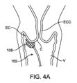
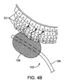
[0005] 図1Aは、女性患者の生殖器を示す。図示の通り、生殖器は、膣V、頸部C、子宮U及びファロピウス管Fを含む。図1Bは、頸部Cを覆っている正常な子宮頸部上皮細胞ECを示す頸部Cの部分の詳細な図を提供する。図1Cは、軽度上皮異形成の発生を示す。上皮異形成は、未熟細胞の増加を含み、対応して成熟細胞の数及び箇所が減少する。異形成は、初期の腫瘍過程を示すことが多い。用語異形成は、一般に、初期のインサイチュ新生物の場合のように、細胞異常が、由来する組織に限定されているときに使用される。軽度異形成は、一般に、上皮の最初の1/3(最も浅い部分)に限定されている。図1Dは、中等度から重度の異形成の発生を示す。中等度異形成は、上皮の次の2/3に限定されており、且つ組織構造によって簡単に区別できない、軽度の病変と高度の病変の混合を表す。重度の異形成は、上皮の2/3を上回って広がる未分化新生細胞を含む。パパニコロー試験で現れる異常細胞は、診断のために、さらなる検査を必要とし得る。そのような診断は、電気外科的ループ切除法(LEEP:loop electrosurgical excision procedure)/移行帯の大ループ切除(LLETZ:large loop excision of the transformation zone)又は円錐切除診/寒冷式円錐切除によって、達成され得る。重度の異形成を越えた状態は、一般に、子宮頸部上皮内癌(CIS:carcinoma in situ)と呼ばれる。 [0005] FIG. 1A illustrates the genital tract of a female patient. As shown, the genital tract includes the vagina V, cervix C, uterus U, and fallopian tubes F. FIG. 1B provides a detailed view of a portion of the cervix C showing normal cervical epithelial cells EC covering the cervix C. FIG. 1C illustrates the occurrence of mild epithelial dysplasia. Epithelial dysplasia includes an increase in immature cells with a corresponding decrease in the number and location of mature cells. Dysplasia often indicates an early neoplastic process. The term dysplasia is generally used when the cellular abnormality is limited to the tissue of origin, as in the case of early in situ neoplasia. Mild dysplasia is generally limited to the first third (the shallowest part) of the epithelium. FIG. 1D illustrates the occurrence of moderate to severe dysplasia. Moderate dysplasia is limited to the next two-thirds of the epithelium and represents a mixture of mild and severe lesions that are not easily distinguished by histology. Severe dysplasia involves undifferentiated neoplastic cells that extend over 2/3 of the epithelium. Abnormal cells that appear on a Pap test may require further testing for diagnosis. Such a diagnosis may be achieved by loop electrosurgical excision procedure (LEP)/large loop excision of the transformation zone (LLETZ) or conization/cold conization. Conditions beyond severe dysplasia are commonly referred to as cervical intraepithelial neoplasia (CIS).
[0006] ステージOは、CISを最も初期の形態の子宮頸癌と分類するが、医師は、一般に前癌状態とみなす。これは、癌細胞が頸部の表層にあるにすぎず、細胞のより深部の層に増殖していないためである。一般にパパニコロー試験で現れるそのような細胞は、診断のためにさらなる検査を必要とし得る。ここでも、そのような診断は、電気外科的ループ切除法(LEEP)/移行帯の大ループ切除(LLETZ)又は円錐切除診/寒冷式円錐切除によって達成され得る。一般に、ステージOでは、これらの処置は、細胞の除去に起因して、効果的な治療としての機能を果たす。 [0006] Stage O classifies CIS as the earliest form of cervical cancer, but doctors generally consider it a precancerous condition. This is because the cancer cells are only on the surface of the cervix and have not grown into deeper layers of cells. Such cells, which generally show up on a Pap test, may require further testing for diagnosis. Again, such a diagnosis may be achieved by loop electrosurgical excision procedure (LEEP)/large loop excision of the transformation zone (LLETZ) or conization/cold conization. Generally, at stage O, these procedures serve as effective treatments due to the removal of cells.
[0007] ステージOを越えると、CISは、様々なステージの癌に分けられる。より初期のステージのいくつかでは、凍結外科及びレーザ外科が治療に使用され得る。より後期のステージは、一般的に、外科手術、放射線、又は化学療法と共に行われる放射線(同時化学放射線療法)を伴う。図2A~2Cは、子宮頸癌のステージIB1及びステージIB2を示す。図示の通り、悪性細胞MCは、上皮細胞ECを越えて、頸部Cのより深部の組織に侵入している。受胎能の維持を望む患者では、骨盤リンパ節郭清による根治的な子宮頸部切除術が治療に用いられ得る。 [0007] Beyond stage O, CIS is divided into various stages of cancer. In some of the earlier stages, cryosurgery and laser surgery may be used for treatment. Later stages generally involve surgery, radiation, or radiation given with chemotherapy (concurrent chemoradiotherapy). Figures 2A-2C show stages IB1 and IB2 of cervical cancer. As shown, the malignant cells MC have invaded beyond the epithelial cells EC into the deeper tissues of the cervix C. In patients who wish to preserve fertility, radical trachelectomy with pelvic lymphadenectomy may be used for treatment.
[0008] CIN及びCISの双方の診断及び治療において起こり得る合併症は、数例を挙げると、感染症、出血、及び組織の除去からの頸部の変化又は瘢痕化を含む。上皮細胞のみを除去することを意図した処置においても、より深部の組織が影響を受けることは多く、瘢痕化につながる。瘢痕化は、脱細胞化組織の正常な細胞再増殖を阻み、且つまた高温/低温への細胞外マトリックス(ECM:extracellular matrix)タンパク質の応答の壊死パターン及び凝固壊死性パターンに関連する。これらの次善の応答及び病変消散パターンは、持続性出血、組織の弾性損失の可能性、及び子宮頸管(cervical lumen)に起こり得る閉塞リスクに関連付けられる。場合によっては、子宮頸管の狭窄は、受胎能を妨げ得、且つ妊娠中に早産の原因となり得る。 [0008] Potential complications in the diagnosis and treatment of both CIN and CIS include infection, bleeding, and cervical changes or scarring from tissue removal, to name a few. Even in procedures intended to remove only epithelial cells, deeper tissues are often affected, leading to scarring. Scarring prevents normal cellular regrowth of the decellularized tissue and is also associated with necrotic and coagulative-necrotic patterns of response of extracellular matrix (ECM) proteins to high/low temperatures. These suboptimal responses and lesion resolution patterns are associated with continued bleeding, possible loss of tissue elasticity, and possible risk of obstruction of the cervical lumen. In some cases, cervical stenosis can impede fertility and can cause premature birth during pregnancy.
[0009] 症例対照研究では、ほぼ2のオッズ比で、CIN病変部の外科的治療と、不妊症又は低受胎のリスクとの関連が見出された。コホート研究では、LEEPから妊娠までの時間間隔が12カ月未満の女性は、12カ月以上と比べて、流産のリスクがそれぞれ4.6%と比べて18%と、自然流産のリスクが著しく高かったという結果となった。他方で、LEEP後の早産のリスクの増加は特定されなかった。しかしながら、大規模なメタ分析では、CINのある女性は、一般集団よりも早産の基礎的リスクが高く、且つCINのための治療としてのLEEPは、おそらくこのリスクをさらに高めるであろうという結果であった。また、早産のリスクは、複数の治療によって、及び除去される組織の量の増加によって、増大するように見える。頸部円錐切除術は、頸管無力に起因して、次の妊娠が平均して約30%早産となるというリスクを生じ得る。 [0009] Case-control studies have found an association between surgical treatment of CIN lesions and the risk of infertility or subfertility, with an odds ratio of approximately 2. Cohort studies have found that women with a time interval of less than 12 months from LEEP to pregnancy had a significantly higher risk of spontaneous abortion compared with those with a time interval of 12 months or more, with a miscarriage risk of 18% compared with 4.6%, respectively. On the other hand, no increased risk of preterm birth after LEEP was identified. However, a large meta-analysis found that women with CIN have a higher baseline risk of preterm birth than the general population, and that LEEP as a treatment for CIN probably further increases this risk. The risk of preterm birth also appears to increase with multiple treatments and with increasing amounts of tissue removed. Cervical conization may result in an average of approximately 30% higher risk of preterm birth in the next pregnancy due to cervical incompetence.
[0010] 診断及び治療のための処置の改善が望まれる。そのような治療は、安全で効果的であり、且つ将来の受胎能に対する影響を含む合併症の減少につながる必要がある。 [0010] Improved diagnostic and therapeutic procedures are desirable. Such treatments should be safe, effective, and lead to fewer complications, including effects on future fertility.
発明の概要
[0011] 本明細書には、標的組織を治療するための装置、システム及び方法の実施形態が説明されている。
Summary of the Invention
[0011] Described herein are embodiments of devices, systems and methods for treating target tissue.
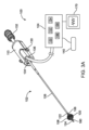
[0012] 第1の態様では、カテーテルが、患者の生殖系内の組織の部位を治療するために提供され、カテーテルは:長尺状シャフトと、長尺状シャフトの遠位端部の近くに配置されたエネルギー送達本体とを含み、長尺状シャフトは、エネルギー送達本体を生殖系内の組織のその部位の近くに又はそれに接して位置決めするように、生殖器内へと進められるように構成されており、及び組織のその部位を治療するように、エネルギーがエネルギー送達本体によって送達できるように、カテーテルは発生器と結合可能である。 [0012] In a first aspect, a catheter is provided for treating a site of tissue within a patient's reproductive system, the catheter including: an elongate shaft; and an energy delivery body disposed near a distal end of the elongate shaft, the elongate shaft configured to be advanced into a genital organ to position the energy delivery body near or in contact with the site of tissue within the reproductive system, and the catheter is connectable to a generator such that energy can be delivered by the energy delivery body to treat the site of tissue.
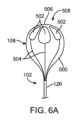
[0013] いくつかの実施形態では、エネルギー送達本体は、患者の頸部の輪郭に対のように合わせられるように構成された形状を有する。例えば、いくつかの実施形態では、エネルギー送達本体はカップ形状を有し、カップ形状は、患者の頸部の輪郭に対のように合わせられるように構成された凹状面を有する。いくつかの実施形態では、エネルギー送達本体はワイヤフォーム(wireform)を含む。いくつかの実施形態では、エネルギー送達本体は、頸部の輪郭に一致するように頸部に対して押し付けることができるように構成された可撓性拡張可能部材を含む。いくつかの実施形態では、可撓性拡張可能部材は1つ以上の可撓性電極を含む。任意選択的に、可撓性拡張可能部材は非導電性材料を含み、及び1つ以上の可撓性電極は1つ以上のパッド電極を含む。 [0013] In some embodiments, the energy delivery body has a shape configured to matingly conform to the contours of the patient's neck. For example, in some embodiments, the energy delivery body has a cup shape, the cup shape having a concave surface configured to matingly conform to the contours of the patient's neck. In some embodiments, the energy delivery body includes a wireform. In some embodiments, the energy delivery body includes a flexible expandable member configured to be pressed against the neck to conform to the contours of the neck. In some embodiments, the flexible expandable member includes one or more flexible electrodes. Optionally, the flexible expandable member includes a non-conductive material, and the one or more flexible electrodes include one or more pad electrodes.
[0014] いくつかの実施形態では、カテーテルは、さらに、エネルギー送達本体が、頸部へエネルギーを送達するために患者の膣の中に存在する間に、カテーテルを安定させるために、患者の子宮内へと進められるように構成された安定化要素を含む。いくつかの実施形態では、安定化要素は、カテーテルの長尺状シャフトのルーメン中を通過するように構成されたシャフトに装着されている。いくつかの実施形態では、安定化要素は、子宮頸管(endocervical canal)内を進められるように構成されたシャフトに装着されている。いくつかの実施形態では、安定化要素は、子宮頸管中を通過できるようにする潰れた形態と、子宮頸管中を通過するのに抵抗する拡張形態とを有する拡張可能部材を含む。 [0014] In some embodiments, the catheter further includes a stabilizing element configured to be advanced into the patient's uterus to stabilize the catheter while the energy delivery body is in the patient's vagina to deliver energy to the cervix. In some embodiments, the stabilizing element is mounted on a shaft configured to pass through a lumen of the elongate shaft of the catheter. In some embodiments, the stabilizing element is mounted on a shaft configured to be advanced through the endocervical canal. In some embodiments, the stabilizing element includes an expandable member having a collapsed configuration that allows passage through the cervical canal and an expanded configuration that resists passage through the endocervical canal.
[0015] いくつかの実施形態では、カテーテルは、さらに、第2のエネルギー送達本体を含む。任意選択的に、エネルギー送達本体及び第2のエネルギー送達本体は、バイポーラ対として機能する。いくつかの実施形態では、エネルギー送達本体及び第2のエネルギー送達本体は、発生器から、異なる波形のエネルギーを受け取るように構成されている。 [0015] In some embodiments, the catheter further includes a second energy delivery body. Optionally, the energy delivery body and the second energy delivery body function as a bipolar pair. In some embodiments, the energy delivery body and the second energy delivery body are configured to receive energy of different waveforms from the generator.
[0016] いくつかの実施形態では、第2のエネルギー送達本体は、エネルギー送達本体が、膣内の組織の部位を治療するために患者の膣の中に存在する間に、子宮内の組織の部位を治療するために、患者の子宮内へと進められるように構成されている。いくつかの実施形態では、エネルギー送達本体及び第2のエネルギー送達本体は、頸部に沿って及び/又は頸部内で細胞の破壊を引き起こすように構成された電界を送達するバイポーラ対として機能する。いくつかの実施形態では、第2のエネルギー送達本体は漏斗形状を有する。いくつかの実施形態では、エネルギー送達本体はカップ形状を有する。いくつかの実施形態では、第1及び第2のエネルギー送達本体は入れ子状にされて、それらの間に頸部組織を保持する。いくつかの実施形態では、第2のエネルギー送達本体は、エネルギー送達本体の長尺状シャフト内にはまり込む第2の長尺状シャフトに装着されている。いくつかの実施形態では、第2のエネルギー送達本体は、エネルギー送達本体が、膣内の組織の部位を治療するために患者の膣の中にある間に、又は子宮内の組織の部位を治療するために患者の子宮の中に存在する間に、子宮頸管内の組織の部位を治療するように、子宮頸管内へと進められるように構成されている。いくつかの実施形態では、第2のエネルギー送達本体は、エネルギー送達本体の長尺状シャフト内にはまり込む第2の長尺状シャフトに装着されている。 [0016] In some embodiments, the second energy delivery body is configured to be advanced into the patient's uterus to treat a site of tissue within the uterus while the energy delivery body is in the patient's vagina to treat a site of tissue within the vagina. In some embodiments, the energy delivery body and the second energy delivery body function as a bipolar pair to deliver an electric field configured to cause cell destruction along and/or within the cervix. In some embodiments, the second energy delivery body has a funnel shape. In some embodiments, the energy delivery body has a cup shape. In some embodiments, the first and second energy delivery bodies are nested to hold cervical tissue between them. In some embodiments, the second energy delivery body is mounted on a second elongate shaft that fits within the elongate shaft of the energy delivery body. In some embodiments, the second energy delivery body is configured to be advanced into the cervical canal to treat a site of tissue within the cervix while the energy delivery body is in the patient's vagina to treat a site of tissue within the vagina or while the energy delivery body is in the patient's uterus to treat a site of tissue within the uterus. In some embodiments, the second energy delivery body is attached to a second elongate shaft that telescopes within the elongate shaft of the energy delivery body.
[0017] いくつかの実施形態では、カテーテルは、さらに、第2のエネルギー送達本体が子宮頸管の中に存在し且つエネルギー送達本体が患者の膣の中に存在する間に、患者の子宮内へと進められるように構成された第3のエネルギー送達本体を含む。いくつかの実施形態では、第2のエネルギー送達本体は、エネルギー送達本体の長尺状シャフト内にはまり込む第2の長尺状シャフトに装着されており、及び第3のエネルギー送達本体は、第2の長尺状シャフト内にはまり込む第3の長尺状シャフトに装着されている。 [0017] In some embodiments, the catheter further includes a third energy delivery body configured to be advanced into the patient's uterus while the second energy delivery body is in the cervical canal and the energy delivery body is in the patient's vagina. In some embodiments, the second energy delivery body is mounted on a second elongate shaft that telescopes within the elongate shaft of the energy delivery body, and the third energy delivery body is mounted on a third elongate shaft that telescopes within the second elongate shaft.
[0018] いくつかの実施形態では、組織のその部位は、生殖器の管腔構造の複数の内表面を含み、及びエネルギー送達本体は、複数の内表面に同時に位置決めできるように拡張するように構成された拡張可能部材を含む。いくつかの実施形態では、拡張可能部材は、患者の子宮を実質的に塞ぐように拡張するように構成されている。いくつかの実施形態では、拡張可能部材は、可撓性の非導電性材料、及び1つ以上の可撓性パッド電極を含む。 [0018] In some embodiments, the site of tissue includes multiple interior surfaces of a genital luminal structure, and the energy delivery body includes an expandable member configured to expand for simultaneous positioning on the multiple interior surfaces. In some embodiments, the expandable member is configured to expand to substantially occlude the patient's uterus. In some embodiments, the expandable member includes a flexible, non-conductive material and one or more flexible pad electrodes.
[0019] いくつかの実施形態では、エネルギー送達本体は、生殖系内の管腔構造の壁に侵入し且つ組織のその部位へエネルギーを送達するように構成されたプローブを含む。いくつかの実施形態では、プローブは、長尺状シャフトの遠位端部から進めることができる。いくつかの実施形態では、プローブはプローブチップを含み、プローブチップは、長尺状シャフトの遠位端部から8cmまで進められることができる。いくつかの実施形態では、長尺状シャフトの遠位端部は、管腔構造の壁を越えて20cmまで進められるように構成されている。いくつかの実施形態では、プローブは複数のプローブ素子を含み、少なくとも1つのプローブ素子は、組織のその部位へエネルギーを送達できる。いくつかの実施形態では、少なくとも2つのプローブ素子はエネルギーを送達でき、及び少なくとも2つのプローブ素子のうちの少なくとも一方は、送達用のエネルギーの受け取りとは無関係に選択可能である。いくつかの実施形態では、少なくとも2つのプローブ素子のそれぞれは、エネルギーを異なる量で同時に送達できる。いくつかの実施形態では、プローブは複数のプローブ素子を含み、各プローブ素子は、組織のその部位へエネルギーを送達できる。いくつかの実施形態では、プローブは複数のプローブ素子を含み、少なくとも1つのプローブ素子は、シャフトから個別に進めることができる。 [0019] In some embodiments, the energy delivery body includes a probe configured to penetrate a wall of a luminal structure in the reproductive system and deliver energy to the site of the tissue. In some embodiments, the probe can be advanced from a distal end of the elongate shaft. In some embodiments, the probe includes a probe tip, and the probe tip can be advanced up to 8 cm from the distal end of the elongate shaft. In some embodiments, the distal end of the elongate shaft is configured to be advanced up to 20 cm beyond the wall of the luminal structure. In some embodiments, the probe includes multiple probe elements, and at least one probe element can deliver energy to the site of the tissue. In some embodiments, at least two probe elements can deliver energy, and at least one of the at least two probe elements is selectable independent of receiving energy for delivery. In some embodiments, each of the at least two probe elements can simultaneously deliver energy in different amounts. In some embodiments, the probe includes multiple probe elements, and each probe element can deliver energy to the site of the tissue. In some embodiments, the probe includes multiple probe elements, and at least one probe element can be individually advanced from the shaft.
[0020] いくつかの実施形態では、プローブは、長尺状シャフトの近位端部から長尺状シャフトの遠位端部まで延在する導電性チューブを含む。いくつかの実施形態では、プローブは、さらに、プローブを発生器に電気的に接続するように構成されたエネルギープラグを含み、エネルギープラグは、導電性チューブに係合するように構成された導電線を含む。いくつかの実施形態では、プローブは、長尺状シャフトの遠位端部の近くに配置されたプローブチップと、長尺状シャフトの近位端部からプローブチップまで延在する導電線とを含む。いくつかの実施形態では、プローブは、プローブチップと、プローブチップを越えて延在するように構成された導電性素子とを含み、導電性素子は、組織のその部位へエネルギーを送達するように構成されている。 [0020] In some embodiments, the probe includes a conductive tube extending from a proximal end of the elongate shaft to a distal end of the elongate shaft. In some embodiments, the probe further includes an energy plug configured to electrically connect the probe to the generator, the energy plug including a conductive wire configured to engage the conductive tube. In some embodiments, the probe includes a probe tip disposed near the distal end of the elongate shaft and a conductive wire extending from the proximal end of the elongate shaft to the probe tip. In some embodiments, the probe includes a probe tip and a conductive element configured to extend beyond the probe tip, the conductive element configured to deliver energy to the site of the tissue.
[0021] いくつかの実施形態では、エネルギー送達本体は、ディスク形状を有する電極を含む。いくつかの実施形態では、ディスク形状は、その直径が長尺状シャフトの長手方向軸に対して実質的に垂直となるように配置される。いくつかの実施形態では、エネルギー送達本体は、ディスク形状を有する電極と実質的に同心であるプローブチップを含む。いくつかの実施形態では、カテーテルは、ディスク形状を有する電極がプローブチップとは異なるエネルギーを送達するように構成されている。 [0021] In some embodiments, the energy delivery body includes an electrode having a disk shape. In some embodiments, the disk shape is arranged such that its diameter is substantially perpendicular to the longitudinal axis of the elongate shaft. In some embodiments, the energy delivery body includes a probe tip that is substantially concentric with the electrode having a disk shape. In some embodiments, the catheter is configured such that the electrode having a disk shape delivers a different energy than the probe tip.
[0022] いくつかの実施形態では、エネルギー送達本体は、バスケット形状の電極を含む。他の実施形態では、エネルギー送達本体は、組織のその部位の近くに位置決めされるように構成されたパドルを含んで、パドルが、組織のその部位へエネルギーを送達できるようにする。 [0022] In some embodiments, the energy delivery body includes a basket-shaped electrode. In other embodiments, the energy delivery body includes a paddle configured to be positioned near the site of tissue such that the paddle delivers energy to the site of tissue.
[0023] いくつかの実施形態では、長尺状シャフトは、さらに、組織のその部位へ流体を送給するように構成された送給ルーメンを含む。 [0023] In some embodiments, the elongate shaft further includes a delivery lumen configured to deliver fluid to the site of tissue.
[0024] 第2の態様では、システムが、患者の生殖系内の組織の部位を治療するために提供され、システムは、本明細書で説明するようなカテーテル;及びカテーテルと結合可能な発生器を含み、発生器は、エネルギーの電気信号を提供するように構成された少なくとも1つのエネルギー送達アルゴリズムを含み、エネルギーは、エネルギー送達本体によって、組織のその部位を治療するように送達できる。 [0024] In a second aspect, a system is provided for treating a site of tissue within a patient's reproductive system, the system including a catheter as described herein; and a generator coupleable to the catheter, the generator including at least one energy delivery algorithm configured to provide an electrical signal of energy, the energy being deliverable by an energy delivery body to treat the site of tissue.
[0025] いくつかの実施形態では、エネルギーは、非熱的エネルギーを含み、及び組織のその部位を治療することは、そのコラーゲン構造を維持しながら、組織のその部位内にある細胞の少なくとも一部分を破壊することを含む。いくつかの実施形態では、組織のその部位は、生殖系の内表面に沿って上皮細胞を含み、及びエネルギー送達本体によって送達できる非熱的エネルギーは、上皮細胞の少なくとも一部分の破壊を引き起こす。いくつかの実施形態では、上皮細胞は、生殖系の頸部に沿って存在する。いくつかの実施形態では、組織のその部位は、生殖系の管腔構造の壁内に存在する。いくつかの実施形態では、組織のその部位は類線維を含む。いくつかの実施形態では、組織のその部位は、ファロピウス管の壁内に存在する。いくつかの実施形態では、少なくとも1つのエネルギー送達アルゴリズムは、組織部位の少なくとも一部分を破壊するように、組織部位へ送達できるエネルギーの電気信号を提供するが、管腔構造の開存性は維持するように構成されている。いくつかの実施形態では、組織のその部位は、望ましくない組織細胞の塊を含み、及び組織のその部位を治療することは、望ましくない組織細胞の塊の少なくとも一部分を破壊することを含む。いくつかの実施形態では、望ましくない組織細胞の塊は、腫瘍、良性腫瘍、悪性腫瘍、類線維、嚢胞、又は病変組織の部位を含む。 [0025] In some embodiments, the energy comprises non-thermal energy, and treating the portion of the tissue comprises destroying at least a portion of the cells within the portion of the tissue while maintaining the collagen structure thereof. In some embodiments, the portion of the tissue comprises epithelial cells along an inner surface of the reproductive system, and the non-thermal energy deliverable by the energy delivery body causes destruction of at least a portion of the epithelial cells. In some embodiments, the epithelial cells are present along the cervix of the reproductive system. In some embodiments, the portion of the tissue is present within a wall of a luminal structure of the reproductive system. In some embodiments, the portion of the tissue comprises fibroids. In some embodiments, the portion of the tissue is present within a wall of a fallopian tube. In some embodiments, at least one energy delivery algorithm is configured to provide an electrical signal of energy deliverable to the tissue portion to destroy at least a portion of the tissue portion, while maintaining patency of the luminal structure. In some embodiments, the portion of the tissue comprises an undesirable mass of tissue cells, and treating the portion of the tissue comprises destroying at least a portion of the undesirable mass of tissue cells. In some embodiments, the mass of unwanted tissue cells comprises a tumor, a benign tumor, a malignant tumor, a fibroid, a cyst, or a site of diseased tissue.
[0026] いくつかの実施形態では、組織のその部位は、生殖系の管腔構造の壁の外部に位置する。いくつかの実施形態では、少なくとも1つのエネルギー送達アルゴリズムは、エネルギー送達本体が管腔構造内に配置されているとき、エネルギー送達本体から、生殖器内の管腔構造の壁の外側から深さ3cmまで送達できる非熱的エネルギーを提供するように構成されている。 [0026] In some embodiments, the site of tissue is located outside a wall of a luminal structure of the reproductive system. In some embodiments, the at least one energy delivery algorithm is configured to provide non-thermal energy from the energy delivery body that can be delivered to a depth of up to 3 cm from outside a wall of a luminal structure in the reproductive system when the energy delivery body is disposed within the luminal structure.
[0027] いくつかの実施形態では、少なくとも1つのエネルギー送達アルゴリズムは、エネルギー送達本体が管腔構造内に配置されているとき、エネルギー送達本体から、生殖器内の管腔構造の壁内へ深さ2mmまで、それを越えずに送達できる非熱的エネルギーを提供するように構成されている。 [0027] In some embodiments, at least one energy delivery algorithm is configured to provide non-thermal energy that can be delivered from the energy delivery body to a depth of up to, but not exceeding, 2 mm into a wall of a luminal structure in the genital tract when the energy delivery body is disposed within the luminal structure.
[0028] いくつかの実施形態では、少なくとも1つのエネルギー送達アルゴリズムは、エネルギー送達本体から、生殖器内の管腔構造の上皮層まで、それを越えずに送達できる非熱的エネルギーを提供するように構成されている。いくつかの実施形態では、管腔構造は、頸部、膣、子宮又は子宮頸管を含む。いくつかの実施形態では、電気信号は、非熱的エネルギーを提供するために、パケットで送られる一連の二相パルスを含む。いくつかの実施形態では、二相パルスのそれぞれは、約100V~10kVの電圧を有する。いくつかの実施形態では、二相パルスのそれぞれは、約500~4000Vの電圧を有する。いくつかの実施形態では、電気信号の周波数は、約100~1000kHzの範囲にある。いくつかの実施形態では、システムは、さらに、エネルギー送達本体からある距離に位置決めできるリターン電極を含み、エネルギー送達本体がモノポーラ式に機能するようにする。 [0028] In some embodiments, the at least one energy delivery algorithm is configured to provide non-thermal energy that can be delivered from the energy delivery body to, but not beyond, an epithelial layer of a luminal structure in the genital tract. In some embodiments, the luminal structure includes the cervix, vagina, uterus, or cervical canal. In some embodiments, the electrical signal includes a series of biphasic pulses delivered in packets to provide the non-thermal energy. In some embodiments, each of the biphasic pulses has a voltage of about 100V to 10 kV. In some embodiments, each of the biphasic pulses has a voltage of about 500 to 4000 V. In some embodiments, the frequency of the electrical signal is in the range of about 100 to 1000 kHz. In some embodiments, the system further includes a return electrode that can be positioned a distance from the energy delivery body such that the energy delivery body functions in a monopolar manner.
[0029] いくつかの実施形態では、カテーテルは第2のエネルギー送達本体を含み、エネルギー送達本体及び第2のエネルギー送達本体は、バイポーラ対として機能し、及び少なくとも1つのエネルギー送達アルゴリズムは、エネルギー送達本体によって送達できるエネルギーの第1の電気信号を提供するように構成された第1のエネルギー送達アルゴリズムと、第2のエネルギー送達本体によって送達できるエネルギーの第2の電気信号を提供するように構成された第2のエネルギー送達アルゴリズムとを含む。 [0029] In some embodiments, the catheter includes a second energy delivery body, the energy delivery body and the second energy delivery body function as a bipolar pair, and the at least one energy delivery algorithm includes a first energy delivery algorithm configured to provide a first electrical signal of energy deliverable by the energy delivery body and a second energy delivery algorithm configured to provide a second electrical signal of energy deliverable by the second energy delivery body.
[0030] いくつかの実施形態では、システムは、さらに、カテーテルによって送給できる液体を含む。任意選択的に、液体は導電性溶液を含む。任意選択的に、液体は補助物質を含み、及びエネルギーは、補助物質の取り込みを促す。いくつかの実施形態では、補助物質は、分子、高分子、又はプラスミドを含む。 [0030] In some embodiments, the system further includes a liquid that can be delivered by the catheter. Optionally, the liquid includes a conductive solution. Optionally, the liquid includes an auxiliary substance, and the energy promotes uptake of the auxiliary substance. In some embodiments, the auxiliary substance includes a molecule, a polymer, or a plasmid.
[0031] 同じように、本発明は、以下の番号の項目に関する。 [0031] Similarly, the present invention relates to the following numbered items:
[0032] 1. 患者の生殖系内の組織の部位を治療する方法であって:
エネルギー送達本体を有する、カテーテルの遠位端部を、生殖系の管腔構造内に挿入すること;
組織のその部位の近くにエネルギー送達本体を位置決めすること;及び
組織のその部位を治療するためにエネルギー送達本体が組織のその部位へエネルギーを送達するように、カテーテルへエネルギーを提供すること
を含む、方法。
[0032] 1. A method of treating a site of tissue within a patient's reproductive system, comprising:
inserting a distal end of a catheter having an energy delivery body into a luminal structure of the reproductive system;
positioning an energy delivery body near the site of tissue; and providing energy to the catheter such that the energy delivery body delivers energy to the site of tissue to treat the site of tissue.
2. エネルギーは、組織のその部位内のコラーゲン構造は維持しながら、組織のその部位内の細胞の少なくとも一部分の破壊を生じる非熱的エネルギーを含む、請求項1に記載の方法。 2. The method of claim 1, wherein the energy comprises non-thermal energy that causes destruction of at least a portion of cells within the tissue while maintaining collagen structure within the tissue.
3. 細胞の少なくとも一部分は、上皮細胞又は扁平細胞を含む、請求項2に記載の方法。
3. The method of
4. 細胞の少なくとも一部分に異形成がある、請求項2に記載の方法。
4. The method of
5. エネルギーは、組織のその部位内の細胞少なくとも一部分の破壊を生じる、請求項2に記載の方法。
5. The method of
6. 細胞の少なくとも一部分に癌がある、請求項5に記載の方法。 6. The method of claim 5, wherein at least a portion of the cells are cancerous.
7. エネルギー送達本体は、患者の頸部の輪郭に対のように合わせられるように構成された形状を有し、及び組織のその部位の近くにエネルギー送達本体を位置決めすることは、エネルギー送達本体を頸部の輪郭に対のように合わせられることを含む、請求項1に記載の方法。 7. The method of claim 1, wherein the energy delivery body has a shape configured to matingly conform to the contours of the patient's neck, and positioning the energy delivery body near the site of tissue includes matingly conforming the energy delivery body to the contours of the neck.
8. エネルギー送達本体はカップ形状を有し、及び対のように合わせられることは、カップ形状の凹状面を頸部の輪郭に接するように位置決めすることを含む、請求項7に記載の方法。 8. The method of claim 7, wherein the energy delivery body has a cup shape and mating includes positioning a concave surface of the cup shape against a contour of the neck.
9. エネルギー送達本体は可撓性材料で構成され、及びエネルギー送達本体を位置決めすることは、エネルギー送達本体を生殖系の管腔構造の内表面に押し付けることを含む、請求項1に記載の方法。 9. The method of claim 1, wherein the energy delivery body is constructed of a flexible material, and positioning the energy delivery body includes pressing the energy delivery body against an inner surface of the luminal structure of the reproductive system.
10. エネルギー送達本体は可撓性拡張可能部材を含み、方法は、さらに、生殖系の管腔構造の内表面に押し付けるために、可撓性拡張可能部材を拡張させることを含む、請求項9に記載の方法。 10. The method of claim 9, wherein the energy delivery body includes a flexible expandable member, and the method further includes expanding the flexible expandable member to press against an inner surface of the luminal structure of the reproductive system.
11. 可撓性拡張可能部材を拡張させることは、患者の子宮を実質的に塞ぐために、可撓性拡張可能部材を拡張させることを含む、請求項10に記載の方法。 11. The method of claim 10, wherein expanding the flexible expandable member includes expanding the flexible expandable member to substantially occlude the patient's uterus.
12. 可撓性拡張可能部材は1つ以上の可撓性電極を含み、及び管腔構造の内表面にエネルギー送達本体を押し付けることは、管腔構造の内表面に、少なくとも1つ以上の可撓性電極のうちの少なくとも1つを押し付けることを含む、請求項9に記載の方法。 12. The method of claim 9, wherein the flexible expandable member includes one or more flexible electrodes, and pressing the energy delivery body against the inner surface of the luminal structure includes pressing at least one of the at least one or more flexible electrodes against the inner surface of the luminal structure.
13. カテーテルは、さらに、安定化要素を含み、方法は、さらに、組織のその部位の近くにエネルギー送達本体の位置を安定させるように、安定化要素を位置決めすることを含む、請求項1に記載の方法。 13. The method of claim 1, wherein the catheter further includes a stabilizing element, and the method further includes positioning the stabilizing element to stabilize the position of the energy delivery body near the site of tissue.
14. 安定化要素を位置決めすることは、患者の子宮内に安定化要素を位置決めすることを含み、及びエネルギー送達本体を位置決めすることは、患者の膣内にエネルギー送達本体を位置決めすることを含む、請求項13に記載の方法。 14. The method of claim 13, wherein positioning the stabilizing element includes positioning the stabilizing element within the patient's uterus, and positioning the energy delivery body includes positioning the energy delivery body within the patient's vagina.
15. 安定化要素は拡張可能部材を含み、方法は、さらに、拡張可能部材が潰れた形態にある間に、拡張可能部材を子宮頸管に通すこと、及び拡張可能部材を子宮内で拡張させて、そのような拡張によって、拡張可能部材が子宮頸管を通って戻るのに抵抗するようにすることを含む、請求項14に記載の方法。
15. The method of
16. カテーテルは、さらに、第2のエネルギー送達機器を含み、方法は、さらに、組織の第2の部位の近くに第2のエネルギー送達機器を位置決めすること、及びカテーテルにエネルギーを提供して、組織の第2の部位を治療するために、第2のエネルギー送達本体が組織の第2の部位にエネルギーを送達するようにすることを含む、請求項1に記載の方法。 16. The method of claim 1, wherein the catheter further includes a second energy delivery device, and the method further includes positioning the second energy delivery device proximate the second site of tissue, and providing energy to the catheter such that the second energy delivery body delivers energy to the second site of tissue to treat the second site of tissue.
17. 組織の第1の部位は患者の膣内に存在し、及び組織の第2の部位は患者の子宮内に存在する、請求項16に記載の方法。
17. The method of
18. カテーテルにエネルギーを提供することは、カテーテルにエネルギーを提供して、エネルギー送達本体が、組織のその部位に、管腔構造の壁内へ深さ2mmまで、それを越えずにエネルギーを送達するようにすることを含む、請求項16に記載の方法。
18. The method of
19. カテーテルにエネルギーを提供することは、カテーテルにエネルギーを提供して、エネルギー送達本体が、組織のその部位に、管腔構造の壁の外側から深さ3cmまでエネルギーを送達するようにすることを含む、請求項16に記載の方法。
19. The method of
20. カテーテルにエネルギーを提供することは、生殖器内にある管腔構造の上皮層まで、それを越えずにエネルギーを提供することを含む、請求項16に記載の方法。
20. The method of
21. 管腔構造は、頸部、膣、子宮又は子宮頸管を含む、請求項1に記載の方法。 21. The method of claim 1, wherein the luminal structure includes the cervix, vagina, uterus, or cervical canal.
22. エネルギーは、パケットで送られる一連の二相パルスを含む電気信号から発生される、請求項1に記載の方法。 22. The method of claim 1, wherein the energy is generated from an electrical signal that includes a series of biphasic pulses delivered in packets.
23. 二相パルスのそれぞれは、約100V~10kVの電圧を有する、請求項22に記載の方法。 23. The method of claim 22, wherein each of the biphasic pulses has a voltage of about 100V to 10 kV.
24. 二相パルスのそれぞれは、約500~4000Vの電圧を有する、請求項23に記載の方法。 24. The method of claim 23, wherein each of the biphasic pulses has a voltage of about 500 to 4000 V.
25. 電気信号の周波数は、約100~1000kHzの範囲内にある、請求項22に記載の方法。 25. The method of claim 22, wherein the frequency of the electrical signal is in the range of about 100 to 1000 kHz.
26. さらに、エネルギー送達本体からある距離にリターン電極を位置決めして、エネルギー送達本体がモノポーラ式に機能するようにすることを含む、請求項1に記載の方法。 26. The method of claim 1, further comprising positioning a return electrode at a distance from the energy delivery body such that the energy delivery body functions in a monopolar manner.
27. さらに、組織のその部位へ液体を送給することを含む、請求項1に記載の方法。 27. The method of claim 1, further comprising delivering a liquid to the site of the tissue.
28. 液体は導電性溶液を含む、請求項27に記載の方法。 28. The method of claim 27, wherein the liquid comprises a conductive solution.
29. 液体は補助物質を含み、及びエネルギーは、補助物質の取り込みを促す、請求項27に記載の方法。 29. The method of claim 27, wherein the liquid includes an auxiliary substance and the energy promotes uptake of the auxiliary substance.
30. 補助物質は、分子、高分子、又はプラスミドを含む、請求項29に記載の方法。 30. The method of claim 29, wherein the auxiliary substance comprises a molecule, a polymer, or a plasmid.
31. 患者の頸部を治療するための方法であって:
エネルギー送達本体を有する、カテーテルの遠位端部を、患者の膣に挿入すること;
頸部の近くにエネルギー送達本体を位置決めすること;
カテーテルにエネルギーを提供して、エネルギー送達本体がエネルギーを頸部の方へ向かって送達し、上皮細胞の一部分の破壊を引き起こすようにすること
を含む、方法。
31. A method for treating a patient's neck, comprising:
inserting a distal end of a catheter having an energy delivery body into a patient's vagina;
Positioning an energy delivery body proximate the neck;
The method includes providing energy to the catheter such that the energy delivery body delivers energy toward the cervix to cause destruction of a portion of the epithelial cells.
32. エネルギーを提供することは、頸部内へ深さ2mmまで、それを越えずに達するエネルギーを提供することを含む、請求項31に記載の方法。 32. The method of claim 31, wherein providing energy includes providing energy to a depth of up to but not exceeding 2 mm into the cervix.
33. エネルギーを提供することは、頸部の壁内へ深さ1mmまで、それを越えずに達するエネルギーを提供することを含む、請求項32に記載の方法。 33. The method of claim 32, wherein providing energy includes providing energy to a depth of up to but not exceeding 1 mm into the cervical wall.
34. エネルギーを提供することは、瘢痕組織を発生させずに、上皮細胞のその部分の破壊を引き起こす、請求項31に記載の方法。 34. The method of claim 31, wherein providing energy causes destruction of the portion of the epithelial cells without causing scar tissue.
35. 上皮細胞に異形成がある、請求項31に記載の方法。 35. The method of claim 31, wherein the epithelial cells have dysplasia.
36. エネルギーは非熱的エネルギーを含み、及び非熱的エネルギーは、頸部のコラーゲン構造を維持しながら、上皮細胞のその部分の破壊を引き起こす、請求項31に記載の方法。 36. The method of claim 31, wherein the energy includes non-thermal energy, and the non-thermal energy causes destruction of the portion of the epithelial cells while preserving the collagen structure of the cervix.
37. 患者の膣を治療するための方法であって:
エネルギー送達本体を有する、カテーテルの遠位端部を、患者の膣に挿入すること;
膣壁の近くにエネルギー送達本体を位置決めすること;
カテーテルにエネルギーを提供して、エネルギー送達本体がエネルギーを膣壁の方へ向かって送達し、膣壁の少なくとも一部分の若返りを引き起こすようにすること
を含む、方法。
37. A method for treating the vagina of a patient, comprising:
inserting a distal end of a catheter having an energy delivery body into a patient's vagina;
Positioning an energy delivery body proximate a vaginal wall;
The method includes providing energy to a catheter such that an energy delivery body delivers energy toward the vaginal wall to cause rejuvenation of at least a portion of the vaginal wall.
38. エネルギーは非熱的エネルギーを含む、請求項37に記載の方法。 38. The method of claim 37, wherein the energy includes non-thermal energy.
39. 若返りは血流量の増大を含む、請求項37に記載の方法。 39. The method of claim 37, wherein the rejuvenation includes increasing blood flow.
40. 若返りは、潤滑性の増加を含む、請求項37に記載の方法。 40. The method of claim 37, wherein the rejuvenation includes increasing lubrication.
41. エネルギー送達本体はワイヤフォームバスケットを含み、及びエネルギー送達本体を位置決めすることは、ワイヤフォームバスケットを拡張させて、膣壁の少なくとも一部分に接触するようにすることを含む、請求項37に記載の方法。 41. The method of claim 37, wherein the energy delivery body includes a wireform basket, and positioning the energy delivery body includes expanding the wireform basket to contact at least a portion of the vaginal wall.
42. エネルギー送達本体を位置決めすることは、ワイヤフォームバスケットを拡張させて、膣壁を有する膣管の周囲に接触するようにすることを含む、請求項41に記載の方法。 42. The method of claim 41, wherein positioning the energy delivery body includes expanding a wireform basket into contact with the periphery of the vaginal canal having the vaginal wall.
43. 患者の組織の部位を治療するためのカテーテルであって:
長尺状シャフト;及び
長尺状シャフトの遠位端部の近くに配置されたエネルギー送達本体
を含み、
長尺状シャフトは、エネルギー送達本体を組織のその部位の近くに又はそれに接して位置決めするように、進められるように構成されており、及び
組織のその部位を治療するように、エネルギーがエネルギー送達本体によって送達できるように、カテーテルは発生器と結合可能である、カテーテル。
43. A catheter for treating a tissue site in a patient, comprising:
an elongate shaft; and an energy delivery body disposed near a distal end of the elongate shaft,
The elongate shaft is configured to be advanced to position the energy delivery body near or in contact with the site of tissue, and the catheter is coupleable to the generator such that energy can be delivered by the energy delivery body to treat the site of tissue.
44. シャフトの遠位端部は、経皮針中を通過するように構成されている、請求項43に記載のカテーテル。 44. The catheter of claim 43, wherein the distal end of the shaft is configured to pass through a percutaneous needle.
45. シャフトは、患者の皮膚を通して経皮的に進められるように構成されている、請求項43に記載のカテーテル。 45. The catheter of claim 43, wherein the shaft is configured to be advanced percutaneously through the patient's skin.
46. 患者の体内の組織の部位を治療するためのシステムであって:
請求署43~45のいずれか1項に記載のカテーテル;及び
カテーテルと結合可能な発生器であって、発生器は、エネルギーの電気信号を提供するように構成された少なくとも1つのエネルギー送達アルゴリズムを含み、エネルギーは、エネルギー送達本体によって、組織のその部位を治療するように送達できる、発生器
を含む、システム。
46. A system for treating a site of tissue within a patient, comprising:
46. A system comprising: a catheter according to any one of claims 43-45; and a generator coupleable to the catheter, the generator including at least one energy delivery algorithm configured to provide an electrical signal of energy, the energy being deliverable by an energy delivery body to treat the site of tissue.
[0033] これらの及び他の実施形態は、添付図面に関連して、以下の説明においてさらに詳細に説明される。
本発明は、例えば、以下の項目を提供する。
(項目1)
患者の生殖系内の組織の部位を治療するためのカテーテルであって:
長尺状シャフト;及び
前記長尺状シャフトの遠位端部の近くに配置されたエネルギー送達本体を含み、
前記長尺状シャフトは、前記エネルギー送達本体を前記生殖系内の組織の前記部位の近くに又はそれに接して位置決めするように、前記生殖器内へと進められるように構成されており、及び
組織の前記部位を治療するように、前記エネルギー送達本体によってエネルギーが送達できるように、前記カテーテルは発生器と結合可能である、カテーテル。
(項目2)
前記エネルギー送達本体は、前記患者の頸部の輪郭に対のように合わせられるように構成された形状を有する、項目1に記載のカテーテル。
(項目3)
前記エネルギー送達本体はカップ形状を有し、前記カップ形状は、前記患者の前記頸部の前記輪郭に対のように合わせられるように構成された凹状面を有する、項目2に記載のカテーテル。
(項目4)
前記エネルギー送達本体はワイヤフォームを含む、項目1~3のいずれか1項に記載のカテーテル。
(項目5)
前記エネルギー送達本体は、前記頸部の輪郭に一致するように前記頸部に対して押し付けることができるように構成された可撓性拡張可能部材を含む、項目1に記載のカテーテル。
(項目6)
前記可撓性拡張可能部材は1つ以上の可撓性電極を含む、項目4に記載のカテーテル。
(項目7)
前記可撓性拡張可能部材は非導電性材料を含み、及び前記1つ以上の可撓性電極は1つ以上のパッド電極を含む、項目5に記載のカテーテル。
(項目8)
さらに、前記エネルギー送達本体が、前記頸部へエネルギーを送達するために前記患者の膣の中に存在する間に、前記カテーテルを安定させるために、前記患者の子宮内へと進められるように構成された安定化要素を含む、項目1~7のいずれか1項に記載のカテーテル。
(項目9)
前記安定化要素は、前記カテーテルの前記長尺状シャフトのルーメン中を通過するように構成されたシャフトに装着されている、項目8に記載のカテーテル。
(項目10)
前記安定化要素は、子宮頸管内を進められるように構成されたシャフトに装着されている、項目8に記載のカテーテル。
(項目11)
前記安定化要素は、前記子宮頸管中を通過できるようにする潰れた形態と、前記子宮頸管中を通過するのに抵抗する拡張形態とを有する拡張可能部材を含む、項目10に記載のカテーテル。
(項目12)
さらに、第2のエネルギー送達本体を含む、項目1~11のいずれか1項に記載のカテーテル。
(項目13)
前記エネルギー送達本体及び前記第2のエネルギー送達本体は、バイポーラ対として機能する、項目12に記載のカテーテル。
(項目14)
前記エネルギー送達本体及び前記第2のエネルギー送達本体は、前記発生器から、異なる波形のエネルギーを受け取るように構成されている、項目12に記載のカテーテル。
(項目15)
前記第2のエネルギー送達本体は、前記エネルギー送達本体が、膣内の組織の部位を治療するために前記患者の前記膣の中に存在する間に、子宮内の組織の部位を治療するために前記患者の前記子宮内へと進められるように構成されている、項目12に記載のカテーテル。
(項目16)
前記エネルギー送達本体及び前記第2のエネルギー送達本体は、前記頸部に沿って及び/又は頸部内で細胞の破壊を引き起こすように構成された電界を送達するバイポーラ対として機能する、項目15に記載のカテーテル。
(項目17)
前記第2のエネルギー送達本体は漏斗形状を有する、項目15又は16に記載のカテーテル。
(項目18)
前記エネルギー送達本体はカップ形状を有する、項目15~17のいずれか1項に記載のカテーテル。
(項目19)
前記第1及び第2のエネルギー送達本体は入れ子状にされて、それらの間に頸部組織を保持する、項目15~18のいずれか1項に記載のカテーテル。
(項目20)
前記第2のエネルギー送達本体は、前記エネルギー送達本体の前記長尺状シャフト内にはまり込む第2の長尺状シャフトに装着されている、項目15~19のいずれか1項に記載のカテーテル。
(項目21)
前記第2のエネルギー送達本体は、前記エネルギー送達本体が、膣内の組織の部位を治療するために前記患者の前記膣の中に、又は子宮内の組織の部位を治療するために前記患者の前記子宮の中に存在する間に、前記子宮頸管内の組織の部位を治療するために子宮頸管内へと進められるように構成されている、項目12に記載のカテーテル。
(項目22)
前記第2のエネルギー送達本体は、前記エネルギー送達本体の前記長尺状シャフト内にはまり込む第2の長尺状シャフトに装着されている、項目21に記載のカテーテル。
(項目23)
さらに、前記第2のエネルギー送達本体が前記子宮頸管の中に存在し及び前記エネルギー送達本体が前記患者の膣の中に存在する間に、前記患者の子宮内へと進められるように構成された第3のエネルギー送達本体を含む、項目21に記載のカテーテル。
(項目24)
前記第2のエネルギー送達本体は、前記エネルギー送達本体の前記長尺状シャフト内にはまり込む第2の長尺状シャフトに装着されており、及び前記第3のエネルギー送達本体は、前記第2の長尺状シャフト内にはまり込む第3の長尺状シャフトに装着されている、項目23に記載のカテーテル。
(項目25)
組織の前記部位は、前記生殖器の管腔構造の複数の内表面を含み、及び前記エネルギー送達本体は、前記複数の内表面に同時に位置決めできるように拡張するように構成された拡張可能部材を含む、項目1~24のいずれか1項に記載のカテーテル。
(項目26)
前記拡張可能部材は、前記患者の子宮を実質的に塞ぐように拡張するように構成されている、項目25に記載のカテーテル。
(項目27)
前記拡張可能部材は、可撓性の非導電性材料、及び1つ以上の可撓性パッド電極を含む、項目25又は26に記載のカテーテル。
(項目28)
前記エネルギー送達本体は、前記生殖系内の管腔構造の壁に侵入し及び組織の前記部位へ前記エネルギーを送達するように構成されたプローブを含む、項目1に記載のカテーテル。
(項目29)
前記プローブは、前記長尺状シャフトの前記遠位端部から進めることができる、項目28に記載のカテーテル。
(項目30)
前記プローブはプローブチップを含み、前記プローブチップは、前記長尺状シャフトの前記遠位端部から8cmまで進められることができる、項目28又は29に記載のカテーテル。
(項目31)
前記長尺状シャフトの前記遠位端部は、前記管腔構造の前記壁を越えて20cmまで進められるように構成されている、項目28又は29に記載のカテーテル。
(項目32)
前記プローブは複数のプローブ素子を含み、少なくとも1つのプローブ素子は、組織の前記部位へ前記エネルギーを送達できる、項目28に記載のカテーテル。
(項目33)
少なくとも2つのプローブ素子は前記エネルギーを送達でき、及び前記少なくとも2つのプローブ素子のうちの少なくとも一方は、送達用の前記エネルギーの受け取りとは無関係に選択可能である、項目32に記載のカテーテル。
(項目34)
前記少なくとも2つのプローブ素子のそれぞれは、前記エネルギーを異なる量で同時に送達できる、項目33に記載のカテーテル。
(項目35)
前記プローブは複数のプローブ素子を含み、各プローブ素子は、組織の前記部位へ前記エネルギーを送達できる、項目28に記載のカテーテル。
(項目36)
前記プローブは複数のプローブ素子を含み、少なくとも1つのプローブ素子は、前記シャフトから個別に進めることができる、項目28に記載のカテーテル。
(項目37)
前記プローブは、前記長尺状シャフトの近位端部から前記長尺状シャフトの前記遠位端部まで延在する導電性チューブを含む、項目28~36のいずれか1項に記載のカテーテル。
(項目38)
さらに、前記プローブを前記発生器に電気的に接続するように構成されたエネルギープラグを含み、前記エネルギープラグは、前記導電性チューブに係合するように構成された導電線を含む、項目37に記載のカテーテル。
(項目39)
前記プローブは、前記長尺状シャフトの前記遠位端部の近くに配置されたプローブチップと、前記長尺状シャフトの近位端部から前記プローブチップまで延在する導電線とを含む、項目28~36のいずれか1項に記載のカテーテル。
(項目40)
前記プローブは、プローブチップと、前記プローブチップを越えて延在するように構成された導電性素子とを含み、前記導電性素子は、組織の前記部位へ前記エネルギーを送達するように構成されている、項目28に記載のカテーテル。
(項目41)
前記エネルギー送達本体は、ディスク形状を有する電極を含む、項目28に記載のカテーテル。
(項目42)
前記ディスク形状は、その直径が前記長尺状シャフトの長手方向軸に対して実質的に垂直となるように配置される、項目41に記載のカテーテル。
(項目43)
前記エネルギー送達本体は、前記ディスク形状を有する前記電極と実質的に同心であるプローブチップを含む、項目41に記載のカテーテル。
(項目44)
カテーテルは、前記ディスク形状を有する前記電極が前記プローブチップとは異なるエネルギーを送達するように構成されている、項目43に記載のカテーテル。
(項目45)
前記エネルギー送達本体は、バスケット形状の電極を含む、項目1に記載のカテーテル。
(項目46)
前記エネルギー送達本体は、組織の前記部位の近くに位置決めされるように構成されたパドルを含んで、前記パドルが、組織の前記部位へ前記エネルギーを送達できるようにする、項目1に記載のカテーテル。
(項目47)
前記長尺状シャフトは、さらに、組織の前記部位へ流体を送給するように構成された送給ルーメンを含む、項目1に記載のカテーテル。
(項目48)
患者の生殖系内の組織の部位を治療するためのシステムであって:
項目1に~47のいずれか1項に記載のカテーテル;及び
前記カテーテルと結合可能な発生器であって、前記発生器は、エネルギーの電気信号を提供するように構成された少なくとも1つのエネルギー送達アルゴリズムを含み、前記エネルギーは、前記エネルギー送達本体によって、組織の前記部位を治療するように送達できる、発生器を含む、システム。
(項目49)
前記エネルギーは非熱的エネルギーを含み、及び組織の前記部位を治療することは、そのコラーゲン構造を維持しながら、組織の前記部位内にある細胞の少なくとも一部分を破壊することを含む、項目48に記載のシステム。
(項目50)
組織の前記部位は、前記生殖系の内表面に沿って上皮細胞を含み、及び前記エネルギー送達本体によって送達できる非熱的エネルギーは、前記上皮細胞の少なくとも一部分の破壊を引き起こす、項目49に記載のシステム。
(項目51)
前記上皮細胞は、前記生殖系の頸部に沿って存在する、項目50に記載のシステム。
(項目52)
組織の前記部位は、前記生殖系の管腔構造の壁内に存在する、項目49に記載のシステム。
(項目53)
組織の前記部位は類線維を含む、項目52に記載のシステム。
(項目54)
組織の前記部位は、ファロピウス管の壁内に存在する、項目52に記載のシステム。
(項目55)
前記少なくとも1つのエネルギー送達アルゴリズムは、前記組織部位の少なくとも一部分を破壊するように、前記組織部位へ送達できる前記エネルギーの前記電気信号を提供するが、前記管腔構造の開存性は維持するように構成されている、項目52に記載のシステム。
(項目56)
組織の前記部位は、望ましくない組織細胞の塊を含み、及び組織の前記部位を治療することは、前記望ましくない組織細胞の塊の少なくとも一部分を破壊することを含む、項目48に記載のシステム。
(項目57)
前記望ましくない組織細胞の塊は、腫瘍、良性腫瘍、悪性腫瘍、類線維、嚢胞、又は病変組織の部位を含む、項目57に記載のシステム。
(項目58)
組織の前記部位は、前記生殖系の管腔構造の壁の外部に位置する、項目48に記載のシステム。
(項目59)
前記少なくとも1つのエネルギー送達アルゴリズムは、前記エネルギー送達本体が前記管腔構造内に配置されているとき、前記エネルギー送達本体から、前記生殖器内の管腔構造の壁の外側から深さ3cmまで送達できる非熱的エネルギーを提供するように構成されている、項目48に記載のシステム。
(項目60)
前記少なくとも1つのエネルギー送達アルゴリズムは、前記エネルギー送達本体が前記管腔構造内に配置されているとき、前記エネルギー送達本体から、前記生殖器内の管腔構造の壁内へ深さ2mmまで、それを越えずに送達できる非熱的エネルギーを提供するように構成されている、項目48に記載のシステム。
(項目61)
前記少なくとも1つのエネルギー送達アルゴリズムは、前記エネルギー送達本体から、前記生殖器内の管腔構造の上皮層まで、それを越えずに送達できる非熱的エネルギーを提供するように構成されている、項目48に記載のシステム。
(項目62)
前記管腔構造は、頸部、膣、子宮又は子宮頸管を含む、項目61に記載のシステム。
(項目63)
前記電気信号は、非熱的エネルギーを提供するために、パケットで送られる一連の二相パルスを含む、項目48~62のいずれか1項に記載のシステム。
(項目64)
前記二相パルスのそれぞれは、約100V~10kVの電圧を有する、項目63に記載のシステム。
(項目65)
前記二相パルスのそれぞれは、約500~4000Vの電圧を有する、項目64に記載のシステム。
(項目66)
前記電気信号の周波数は約100~1000kHzの範囲である、項目63に記載のシステム。
(項目67)
さらに、前記エネルギー送達本体がモノポーラ式に機能するように、前記エネルギー送達本体からある距離に位置決めできるリターン電極を含む、項目63に記載のシステム。
(項目68)
前記カテーテルは第2のエネルギー送達本体を含み、前記エネルギー送達本体及び前記第2のエネルギー送達本体はバイポーラ対として機能し、及び前記少なくとも1つのエネルギー送達アルゴリズムは、前記エネルギー送達本体によって送達できるエネルギーの第1の電気信号を提供するように構成された第1のエネルギー送達アルゴリズムと、前記第2のエネルギー送達本体によって送達できるエネルギーの第2の電気信号を提供するように構成された第2のエネルギー送達アルゴリズムとを含む、項目48に記載のシステム。
(項目69)
さらに、前記カテーテルによって送給できる液体を含む、項目48~68のいずれか1項に記載のシステム。
(項目70)
前記液体は導電性溶液を含む、項目69に記載のシステム。
(項目71)
前記液体は補助物質を含み、及び前記エネルギーは前記補助物質の取り込みを促す、項目69に記載のシステム。
(項目72)
前記補助物質は、分子、高分子、又はプラスミドを含む、項目71に記載のシステム。
[0033] These and other embodiments are described in further detail in the following description, taken in conjunction with the accompanying drawings.
The present invention provides, for example, the following items.
(Item 1)
1. A catheter for treating a site of tissue within a patient's reproductive system, comprising:
an elongate shaft; and
an energy delivery body disposed near a distal end of the elongate shaft;
the elongate shaft is configured to be advanced into the reproductive organs to position the energy delivery body proximate or adjacent to the site of tissue in the reproductive system; and
The catheter is coupleable to a generator such that energy can be delivered by the energy delivery body to treat the site of tissue.
(Item 2)
2. The catheter of claim 1, wherein the energy delivery body has a shape configured to matingly conform to the contours of the patient's neck.
(Item 3)
3. The catheter of
(Item 4)
4. The catheter of any one of claims 1 to 3, wherein the energy delivery body comprises a wireform.
(Item 5)
2. The catheter of claim 1, wherein the energy delivery body includes a flexible, expandable member configured to be compressible against the neck to conform to the contours of the neck.
(Item 6)
5. The catheter of claim 4, wherein the flexible expandable member comprises one or more flexible electrodes.
(Item 7)
6. The catheter of claim 5, wherein the flexible expandable member comprises a non-conductive material and the one or more flexible electrodes comprise one or more pad electrodes.
(Item 8)
8. The catheter of any one of items 1-7, further comprising a stabilization element configured to be advanced into the patient's uterus to stabilize the catheter while the energy delivery body is in the patient's vagina for delivering energy to the cervix.
(Item 9)
9. The catheter of claim 8, wherein the stabilization element is mounted on a shaft configured to pass through a lumen of the elongate shaft of the catheter.
(Item 10)
9. The catheter of claim 8, wherein the stabilization element is attached to a shaft configured for advancement within the cervical canal.
(Item 11)
11. The catheter of claim 10, wherein the stabilizing element comprises an expandable member having a collapsed configuration that allows passage through the cervical canal and an expanded configuration that resists passage through the cervical canal.
(Item 12)
12. The catheter of any one of items 1 to 11, further comprising a second energy delivery body.
(Item 13)
Item 13. The catheter of item 12, wherein the energy delivery body and the second energy delivery body function as a bipolar pair.
(Item 14)
13. The catheter of claim 12, wherein the energy delivery body and the second energy delivery body are configured to receive energy of different waveforms from the generator.
(Item 15)
13. The catheter of claim 12, wherein the second energy delivery body is configured to be advanced into the patient's uterus to treat a site of tissue within the uterus while the energy delivery body is present in the patient's vagina to treat a site of tissue within the vagina.
(Item 16)
16. The catheter of claim 15, wherein the energy delivery body and the second energy delivery body function as a bipolar pair to deliver an electric field configured to cause destruction of cells along and/or within the cervix.
(Item 17)
17. The catheter of
(Item 18)
18. The catheter of any one of items 15 to 17, wherein the energy delivery body has a cup shape.
(Item 19)
19. The catheter of any one of items 15 to 18, wherein the first and second energy delivery bodies are nested to hold cervical tissue therebetween.
(Item 20)
20. The catheter of any one of claims 15 to 19, wherein the second energy delivery body is attached to a second elongate shaft that telescopes within the elongate shaft of the energy delivery body.
(Item 21)
13. The catheter of claim 12, wherein the second energy delivery body is configured to be advanced into the cervical canal to treat a site of tissue within the cervix while the energy delivery body is present in the patient's vagina to treat a site of tissue within the vagina or in the patient's uterus to treat a site of tissue within the uterus.
(Item 22)
22. The catheter of claim 21, wherein the second energy delivery body is attached to a second elongate shaft that telescopes within the elongate shaft of the energy delivery body.
(Item 23)
22. The catheter of claim 21, further comprising a third energy delivery body configured to be advanced into the patient's uterus while the second energy delivery body is in the cervical canal and the energy delivery body is in the patient's vagina.
(Item 24)
24. The catheter of claim 23, wherein the second energy delivery body is attached to a second elongate shaft that telescopes within the elongate shaft of the energy delivery body, and the third energy delivery body is attached to a third elongate shaft that telescopes within the second elongate shaft.
(Item 25)
25. The catheter of any one of items 1 to 24, wherein the site of tissue includes multiple inner surfaces of a luminal structure of the reproductive organs, and the energy delivery body includes an expandable member configured to expand so as to be simultaneously positionable against the multiple inner surfaces.
(Item 26)
26. The catheter of claim 25, wherein the expandable member is configured to expand to substantially occlude a uterus of the patient.
(Item 27)
27. The catheter of claim 25 or 26, wherein the expandable member comprises a flexible, non-conductive material and one or more flexible pad electrodes.
(Item 28)
2. The catheter of claim 1, wherein the energy delivery body includes a probe configured to penetrate a wall of a luminal structure within the reproductive system and deliver the energy to the site of tissue.
(Item 29)
30. The catheter of claim 28, wherein the probe is advanceable from the distal end of the elongate shaft.
(Item 30)
30. The catheter of claim 28 or 29, wherein the probe includes a probe tip, the probe tip being capable of being advanced up to 8 cm from the distal end of the elongate shaft.
(Item 31)
30. The catheter of claim 28 or 29, wherein the distal end of the elongate shaft is configured to be advanced up to 20 cm beyond the wall of the luminal structure.
(Item 32)
30. The catheter of claim 28, wherein the probe includes multiple probe elements, at least one probe element capable of delivering the energy to the site of tissue.
(Item 33)
33. The catheter of claim 32, wherein at least two probe elements are capable of delivering the energy, and at least one of the at least two probe elements is selectable independently of receiving the energy for delivery.
(Item 34)
34. The catheter of claim 33, wherein each of the at least two probe elements is capable of simultaneously delivering different amounts of the energy.
(Item 35)
30. The catheter of claim 28, wherein the probe includes a plurality of probe elements, each probe element capable of delivering the energy to the site of tissue.
(Item 36)
30. The catheter of claim 28, wherein the probe includes multiple probe elements, at least one probe element being individually advanceable from the shaft.
(Item 37)
37. The catheter of any one of claims 28 to 36, wherein the probe includes a conductive tube extending from a proximal end of the elongate shaft to the distal end of the elongate shaft.
(Item 38)
38. The catheter of claim 37, further comprising an energy plug configured to electrically connect the probe to the generator, the energy plug comprising a conductive wire configured to engage the conductive tube.
(Item 39)
37. The catheter of any one of claims 28 to 36, wherein the probe includes a probe tip disposed near the distal end of the elongate shaft and a conductive wire extending from the proximal end of the elongate shaft to the probe tip.
(Item 40)
30. The catheter of claim 28, wherein the probe includes a probe tip and a conductive element configured to extend beyond the probe tip, the conductive element configured to deliver the energy to the site of tissue.
(Item 41)
30. The catheter of claim 28, wherein the energy delivery body includes an electrode having a disk shape.
(Item 42)
42. The catheter of claim 41, wherein the disk shape is positioned such that its diameter is substantially perpendicular to the longitudinal axis of the elongate shaft.
(Item 43)
42. The catheter of claim 41, wherein the energy delivery body includes a probe tip that is substantially concentric with the electrode having the disk shape.
(Item 44)
44. The catheter of claim 43, wherein the electrode having the disk shape is configured to deliver a different energy than the probe tip.
(Item 45)
2. The catheter of claim 1, wherein the energy delivery body comprises a basket-shaped electrode.
(Item 46)
2. The catheter of claim 1, wherein the energy delivery body includes a paddle configured to be positioned near the site of tissue such that the paddle delivers the energy to the site of tissue.
(Item 47)
2. The catheter of claim 1, wherein the elongate shaft further comprises a delivery lumen configured to deliver a fluid to the site of tissue.
(Item 48)
1. A system for treating a site of tissue within a patient's reproductive system, comprising:
A catheter according to any one of items 1 to 47; and
A system comprising: a generator coupleable to the catheter, the generator including at least one energy delivery algorithm configured to provide an electrical signal of energy, the energy being deliverable by the energy delivery body to treat the site of tissue.
(Item 49)
50. The system of claim 48, wherein the energy comprises non-thermal energy and treating the site of tissue comprises destroying at least a portion of cells within the site of tissue while maintaining its collagen structure.
(Item 50)
50. The system of claim 49, wherein the site of tissue comprises epithelial cells along an inner surface of the reproductive system, and the non-thermal energy deliverable by the energy delivery body causes destruction of at least a portion of the epithelial cells.
(Item 51)
51. The system of claim 50, wherein the epithelial cells are present along a cervix of the reproductive system.
(Item 52)
50. The system of claim 49, wherein the site of tissue is within a wall of a luminal structure of the reproductive system.
(Item 53)
53. The system of claim 52, wherein the region of tissue comprises a fibroid.
(Item 54)
53. The system of claim 52, wherein the site of tissue is within the wall of a fallopian tube.
(Item 55)
53. The system of claim 52, wherein the at least one energy delivery algorithm is configured to provide the electrical signal of energy deliverable to the tissue site to destroy at least a portion of the tissue site while maintaining patency of the luminal structure.
(Item 56)
50. The system of claim 48, wherein the site of tissue includes an undesirable tissue cell mass, and treating the site of tissue includes destroying at least a portion of the undesirable tissue cell mass.
(Item 57)
58. The system of claim 57, wherein the mass of unwanted tissue cells comprises a tumor, a benign tumor, a malignant tumor, a fibroid, a cyst, or a site of diseased tissue.
(Item 58)
50. The system of claim 48, wherein the site of tissue is located external to a wall of a luminal structure of the reproductive system.
(Item 59)
49. The system of claim 48, wherein the at least one energy delivery algorithm is configured to provide non-thermal energy from the energy delivery body when the energy delivery body is disposed within the luminal structure, the non-thermal energy being deliverable from the energy delivery body to a depth of up to 3 cm from the exterior of a wall of a luminal structure within the genitalia.
(Item 60)
49. The system of claim 48, wherein the at least one energy delivery algorithm is configured to provide non-thermal energy that can be delivered from the energy delivery body to a depth of up to, but not exceeding, 2 mm into a wall of a luminal structure in the genitalia when the energy delivery body is disposed within the luminal structure.
(Item 61)
49. The system of claim 48, wherein the at least one energy delivery algorithm is configured to provide non-thermal energy that can be delivered from the energy delivery body to but not beyond an epithelial layer of a luminal structure within the genital tract.
(Item 62)
62. The system of claim 61, wherein the luminal structure comprises the cervix, vagina, uterus, or cervical canal.
(Item 63)
63. The system of any one of claims 48 to 62, wherein the electrical signal includes a series of biphasic pulses delivered in packets to provide non-thermal energy.
(Item 64)
Item 64. The system of item 63, wherein each of the biphasic pulses has a voltage of about 100V to 10 kV.
(Item 65)
65. The system of claim 64, wherein each of the biphasic pulses has a voltage of about 500-4000V.
(Item 66)
Item 64. The system of item 63, wherein the frequency of the electrical signal is in the range of approximately 100 to 1000 kHz.
(Item 67)
Item 64. The system of item 63, further comprising a return electrode positionable at a distance from the energy delivery body such that the energy delivery body functions in a monopolar manner.
(Item 68)
49. The system of claim 48, wherein the catheter includes a second energy delivery body, the energy delivery body and the second energy delivery body function as a bipolar pair, and the at least one energy delivery algorithm includes a first energy delivery algorithm configured to provide a first electrical signal of energy deliverable by the energy delivery body, and a second energy delivery algorithm configured to provide a second electrical signal of energy deliverable by the second energy delivery body.
(Item 69)
69. The system of any one of claims 48 to 68, further comprising a liquid deliverable by the catheter.
(Item 70)
70. The system of claim 69, wherein the liquid comprises a conductive solution.
(Item 71)
70. The system of claim 69, wherein the liquid contains an auxiliary substance and the energy promotes uptake of the auxiliary substance.
(Item 72)
72. The system of
参照による援用
[0034] 本明細書で述べる全ての刊行物、特許、及び特許出願は、それぞれ個々の刊行物、特許、又は特許出願が参照することにより援用されるように具体的に及び個々に示されたのと同じ程度で、参照することにより援用される。
Incorporation by Reference
[0034] All publications, patents, and patent applications mentioned in this specification are incorporated by reference to the same extent as if each individual publication, patent, or patent application was specifically and individually indicated to be incorporated by reference.
[0035] 必ずしも縮尺通りではない図面では、同様の参照符号が異なる図面において同様の構成要素を説明し得る。異なる文字の接尾語のある同様の参照符号は、同様の構成要素の異なる例を表し得る。図面は、全体的に、限定ではなく、例を示し、本明細書の様々な実施形態が説明されている。 [0035] In the drawings, which are not necessarily to scale, like reference numbers may describe like components in different drawings. Like reference numbers with different letter suffixes may represent different examples of like components. The drawings generally illustrate by way of example, and not by way of limitation, in which various embodiments herein are illustrated.
詳細な説明
[0080] 生殖器の状態、場合によっては、生殖器の内層に関連付けられた状態を治療するための機器、システム及び方法が提供される。いくつかの状態は、内層及び解剖学的構造内のより深部にある細胞層を悩まし得る。例えば、子宮頸部異形成としても周知の子宮頸部上皮内腫瘍(CIN)は、頸部の表面上での異常な細胞増殖を伴う状態であり、これは、子宮頸部上皮内癌(CIS:cancer in situ)に至る可能性がある。他の状態は、数例を挙げると、ヒトパピローマウィルス(HPV)関連の子宮頸疾患、様々な子宮内膜疾患、急性及び慢性子宮頸管炎、並びに様々な感染症(例えばトリコモナス症)を含む。そのような状態は、生殖器の様々な部分、例えば膣、頸部、子宮頸管、及び子宮に影響を及ぼし得る。子宮に特有の状態は、異常子宮出血、例えば月経過多又は不正子宮出血を引き起こすようなものを含み得る。悪性ではないそのような状態は、ポリープ、分泌期子宮内膜及び子宮内膜炎を含む。悪性の原因は、単純性及び複雑型増殖症を含み、子宮内膜癌に至る。異常子宮出血の他の原因は、類線維又は平滑筋腫を含む。本明細書で説明する機器、システム及び方法は、そのような状態を他のものと併せて治療するのに特に好適である。
Detailed Description
[0080] Devices, systems and methods are provided for treating conditions of the reproductive organs, in some cases conditions associated with the reproductive lining. Some conditions may afflict the lining and layers of cells deeper within the anatomy. For example, cervical intraepithelial neoplasia (CIN), also known as cervical dysplasia, is a condition involving abnormal cell proliferation on the surface of the cervix, which may lead to cervical intraepithelial carcinoma (CIS). Other conditions include human papillomavirus (HPV)-related cervical disease, various endometrial diseases, acute and chronic cervicitis, and various infections (e.g., trichomoniasis), to name a few. Such conditions may affect various parts of the reproductive organs, such as the vagina, cervix, cervix, and uterus. Conditions specific to the uterus may include those that cause abnormal uterine bleeding, such as menorrhagia or irregular uterine bleeding. Such conditions that are not malignant include polyps, secretory endometrium, and endometritis. Malignant causes include simple and complex hyperplasia, leading to endometrial cancer. Other causes of abnormal uterine bleeding include fibroids or leiomyomas. The devices, systems and methods described herein are particularly well suited to treating such conditions, among others.
[0081] 本明細書で説明する機器、システム及び方法は、病変細胞、損傷細胞、異常細胞又はその他の望ましくない細胞を取り除き、組織のフレームワークを無傷のままにする。これは、組織が正常に再生できるようにし、瘢痕組織の形成を回避する。瘢痕化は、組織のフレームワークが損傷されるか又は除去されるときに発生する。そのような場合には、組織のフレームワークの修復は、同じタンパク質(コラーゲン)を導入して置き換えることを含むが、タンパク質の線維組成及び構成は、正常組織のものとは異なる。正常組織に見られるコラーゲン線維のランダムなバスケット織構造の代わりに、線維症では、コラーゲンは架橋し、且つ一方向に顕著な整列を形成する。このコラーゲン瘢痕組織の整列は、通常、正常なコラーゲンのランダムな整列よりも機能性品質が低い。その結果、瘢痕組織となる。対照的に、組織のフレームワークが無傷のままであるとき、フレームワーク構造は、健康な細胞で再増殖し、構造特性を変えることなく、正常組織を再生する。 [0081] The devices, systems and methods described herein remove diseased, damaged, abnormal or otherwise undesirable cells and leave the tissue framework intact. This allows the tissue to regenerate normally and avoids the formation of scar tissue. Scarring occurs when the tissue framework is damaged or removed. In such cases, repair of the tissue framework involves introducing and replacing the same protein (collagen), but the fiber composition and organization of the protein is different from that of normal tissue. Instead of the random basket weave structure of collagen fibers seen in normal tissue, in fibrosis, collagen crosslinks and forms a pronounced alignment in one direction. This alignment of collagen scar tissue is usually of lower functional quality than the random alignment of normal collagen. The result is scar tissue. In contrast, when the tissue framework is left intact, the framework structure repopulates with healthy cells and regenerates normal tissue without altering its structural properties.
[0082] 組織のフレームワークを保ち、それにより、瘢痕化などの合併症を減少させるか又はなくすような治療は、特定のパラメータ設定でパルス電界(PEF:pulsed electric fields)を送る特殊なエネルギー送達機器を使用することによって、達成される。PEFは、標的組織領域に又はその近くに配置された少なくとも1つの電極を通して、送られる。これらのPEFは、病的細胞を不安定にし、それに続いて細胞死を生じる。場合によっては、これは、状態を完全に治療する。他の場合には、これは、癌の病期の低下の場合など、状態の重症度を軽減し、これにより、首尾よく取り除くために他の治療法を使用できるようにし得る。 [0082] Treatment that preserves the tissue framework, thereby reducing or eliminating complications such as scarring, is accomplished by using specialized energy delivery devices that deliver pulsed electric fields (PEF) at specific parameter settings. The PEFs are delivered through at least one electrode placed at or near the target tissue area. These PEFs destabilize the diseased cells, resulting in subsequent cell death. In some cases, this completely cures the condition. In other cases, this may reduce the severity of the condition, such as in the case of downstaging of cancer, thereby allowing the use of other therapies to successfully eliminate it.
[0083] 一般的に、電極又は電極のアレイが、生殖器の内層、任意選択的に頸部Cを覆っている上皮細胞ECなどの標的組織の近くに又はそれと接触して配置される。いくつかの実施形態では、1つ又は複数の電極は、導電性物質と接触して位置決めされ、これは、同様に、標的組織と接触していることが認識され得る。そのような溶液は、等張溶液又は高張溶液を含み得る。これらの溶液は、さらに、補助物質、例えば化学療法又はカルシウムを含み得、病巣治療並びに標的組織型の潜在的な局所的な浸潤領域の双方の治療の有効性をさらに高める。モノポーラ配置構成では、分散電極は外部に、例えば患者の皮膚に位置決めされる。その後、高電圧の短い持続時間の二相電気パルスが、標的組織の近くに、1つ又は複数の電極を通して送られる。誘導電界は、組織-電極境界面において最強であり、且つ離れるにつれて、致死電界閾値を下回るまで減衰し、これは、二次パラメータ(例えばパケット持続時間、パケット数/パケットカウント、周波数、及びパケットタイミング)に基づく。電界が致死電界閾値を上回る組織領域内にある細胞は、死滅する。それゆえ、治療は、標的細胞(例えば、潜在的に異常な/新生/異形成細胞)が、直接殺されるか、又はある種の補助物質の取り込みからの治療又は効果の影響をより受けやすくする一方で、周囲組織は保存されて、その機能を維持し、且ついずれの有害事象又は副次的な罹患率の可能性も減少させるように設計される。 [0083] In general, an electrode or an array of electrodes is placed near or in contact with a target tissue, such as the epithelial cells EC lining the genital tract, optionally covering the cervix C. In some embodiments, one or more electrodes are positioned in contact with a conductive material, which may also be recognized as being in contact with the target tissue. Such solutions may include isotonic or hypertonic solutions. These solutions may further include supplemental substances, such as chemotherapy or calcium, to further enhance the effectiveness of both the focal treatment as well as the treatment of potential localized areas of invasion of the target tissue type. In a monopolar configuration, a dispersive electrode is positioned externally, for example on the patient's skin. A high voltage, short duration, biphasic electrical pulse is then delivered through one or more electrodes near the target tissue. The induced electric field is strongest at the tissue-electrode interface and decays with distance until it falls below the lethal electric field threshold, which is based on secondary parameters (e.g., packet duration, packet number/packet count, frequency, and packet timing). Cells within the tissue region where the electric field exceeds the lethal electric field threshold are killed. Thus, the treatment is designed so that the target cells (e.g., potentially abnormal/neoplastic/dysplastic cells) are either killed directly or made more susceptible to treatment or effects from the incorporation of certain auxiliary substances, while the surrounding tissue is preserved, maintaining its function and reducing the likelihood of any adverse events or secondary morbidity.
例示的な実施形態の概説
[0084] 一般に、PEFを送る電極又は電極のアレイは、標的組織部位まで進められるように構成された治療エネルギー送達カテーテルに配置されている。生殖器の様々な部分へのアクセスは、一般に、膣Vを通してアクセスされる。図3Aは、治療エネルギー送達カテーテル102の基本的な実施形態を示す。この実施形態では、カテーテル102は、長尺状シャフト106を有し、少なくとも1つのエネルギー送達本体108がその遠位端部の近くにあり、及びハンドル110がその近位端部にある。カテーテル102は、治療システム100の一部としての発生器104に接続可能である。発生器104へのカテーテル102の接続によって、いくつかある特徴の中で特に、エネルギー送達本体108へ電気エネルギーをもたらす。この実施形態では、エネルギー送達本体108は、近位端部束縛部122及び遠位端部束縛部124によって束縛される複数のワイヤ又はリボン120を含み、且つ電極としての機能を果たす螺旋形のバスケットを形成する。代替的な実施形態では、ワイヤ又はリボンは、螺旋形に形成される代わりに、直線に形成される(すなわち、直線形状のバスケットを形成するように構成される)。さらに別の実施形態では、エネルギー送達本体108は、チューブからレーザ切断される。様々な他の設計を使用してもよいことが認識され得る。例えば、図3Bは、パドル形状を有するエネルギー送達本体108を示す。この実施形態では、エネルギー送達本体108は、平らなパッド又はパドルを形成するように配置された複数のワイヤ又はリボン120で構成される。そのようなエネルギー送達本体108は可撓性であり、シャフト106内へと後退される。図3Aに戻ると、いくつかの実施形態では、エネルギー送達本体108は、自己拡張型であり、且つ潰れた形態で標的部位へ送出される。この潰れた形態は、例えば、エネルギー送達本体108の上側を覆ってシース126を配置することによって、達成され得る。カテーテルシャフト106(シース126内)は、近位端部束縛部122で終端し、遠位端部束縛部124を本質的に軸方向に束縛されていない状態にし、且つカテーテル102のシャフト106に対して自由に動けるようにする。エネルギー送達本体108の上側にわたってシース126を進めることによって、遠位端部束縛部124を前方へ動かすことができ、それにより、エネルギー送達本体108を長くして/潰して、束縛する。
Overview of Exemplary Embodiments
[0084] Typically, an electrode or array of electrodes that delivers PEF is disposed in a therapeutic energy delivery catheter configured to be advanced to a target tissue site. Access to the various parts of the genitalia is typically gained through the vagina V. FIG. 3A shows a basic embodiment of a therapeutic
[0085] この例に示すように、カテーテル102は、その近位端部にハンドル110を含む。いくつかの実施形態では、ハンドル110は、ハンドル取り外しボタン130を押すことなどによって、取り外し自在である。この実施形態では、ハンドル110は、エネルギー送達本体操作ノブ132を含み、ノブ132の動きによって、バスケット形状の電極の拡張又は後退/潰れを引き起こす。この例では、ハンドル110はまた、内視鏡、子宮鏡又は他のタイプの可視化デバイスとの任意選択的な接続のためのワーキングポートスナップ部134、及び発生器104との接続のためのケーブル差込口136を含む。様々なタイプの可視化が使用され得ることが認識され得る。一般に、生殖器は、検鏡を使用してアクセスされ、及び直接可視化又はダイレクトビデオ可視化が使用される。いくつかの実施形態では、特に、膣から離れたところに位置する生殖器の複数の部分にアクセスするとき、数例を挙げると、血管造影法(任意選択的にマーカを含む)、コンピュータ断層撮影法、光干渉断層法、及び超音波を含む、他のタイプの可視化が使用されてもよい。
[0085] As shown in this example, the
[0086] この実施形態では、治療エネルギー送達カテーテル102は、患者Pの皮膚に外部から取り付けられる分散(リターン)電極140と一緒に、発生器104と接続可能である。それゆえ、この実施形態では、モノポーラエネルギー送達は、カテーテル102の遠位端部の近くに配置されたエネルギー送達本体108とリターン電極140との間にエネルギーを供給することによって、達成される。しかしながら、バイポーラエネルギー送達及び他の配置構成が代わりに使用されてもよいことが認識される。バイポーラエネルギー送達を使用するとき、治療エネルギー送達カテーテル102は、全体的な設計が異なって、複数のエネルギー送達本体108を含むようにしてもよいし、又は全体的な設計は同様に見えて、バイポーラ式に機能するように構成される単一のエネルギー送達本体108を含むようにしてもよい(例えば、エネルギー送達本体108は、バイポーラ式に機能する複数の電極を含む)。場合によっては、バイポーラエネルギー送達は、モノポーラエネルギー送達と比べると、治療効果を達成するために、より低い電圧の使用を可能にする。いくつかのバイポーラ形態では、陽極及び陰極は、互いに十分に近くにされて、電極の両極に及び電極の両極間にの双方で治療効果をもたらす。これは、より大きく、より浅い表面領域にわたって治療効果を波及し得るため、モノポーラと比べて、治療効果を達成するために必要な電圧をより低くする。同じように、侵入深さを浅くするために、このより低い電圧が使用されてもよい。
[0086] In this embodiment, the therapeutic
[0087] この実施形態では、発生器104は、ユーザインターフェース150、1つ以上のエネルギー送達アルゴリズム152、プロセッサー154、データ記憶/検索ユニット156(メモリ及び/又はデータベースなど)、及び送達されることになるエネルギーを発生させ且つ蓄積するエネルギー蓄積サブシステム158を含む。いくつかの実施形態では、1つ以上のコンデンサがエネルギー蓄積/送達のために使用されるが、任意の他の好適なエネルギー蓄積素子が使用されてもよい。さらに、1つ以上の通信ポートが含まれる。
[0087] In this embodiment, the
[0088] いくつかの実施形態では、発生器104は、3つのサブシステム:1)高エネルギー蓄積システム、2)高電圧・中周波スイッチング増幅器、及び3)システムコントローラ、ファームウェア、及びユーザインターフェースを含む。生殖器を治療するときには必要とされる可能性は低いが、いくつかの実施形態では、システムコントローラは、パルス状エネルギー出力を患者の心調律に同期させることができる心拍同期駆動方式トリガーモニタを含む。発生器は、交流電流(AC)電源から取り込んで、複数の直流(DC)電源装置に給電する。発生器のコントローラは、エネルギー送達が開始される前に、DC電源装置に、高エネルギーコンデンサ蓄積バンクを充電させるようにし得る。治療エネルギー送達の開始時、発生器のコントローラ、高エネルギー蓄積バンク及び二相パルス増幅器は、高電圧の中周波出力を生み出すように同時に動作し得る。
[0088] In some embodiments, the
[0089] エネルギー送達アルゴリズムを実行するために多数の発生器電気アーキテクチャが用いられ得ることが認識される。特に、いくつかの実施形態では、パルス電界回路を、同じエネルギー蓄積及び高電圧付与システムとは別のエネルギー送達電極へ切り替えることができる高度のスイッチングシステムが使用される。さらに、急変するパルスパラメータ(例えば、電圧、周波数など)又は複数のエネルギー送達電極を用いる、高度のエネルギー送達アルゴリズムにおいて用いられる発生器は、モジュール式エネルギー蓄積及び/又は高電圧システムを利用し、高度にカスタマイズ可能な波形及び地理的なパルス送達パラダイムを容易にし得る。本明細書で上述した電気アーキテクチャは、例にすぎず、パルス電界を送達するシステムは、追加的なスイッチング増幅器構成要素を含んでも又は含まなくてもよいことをさらに認識されるべきである。 [0089] It is recognized that numerous generator electrical architectures may be used to implement the energy delivery algorithm. In particular, in some embodiments, advanced switching systems are used that can switch the pulsed electric field circuit to another energy delivery electrode from the same energy storage and high voltage application system. Additionally, generators used in advanced energy delivery algorithms that use rapidly changing pulse parameters (e.g., voltage, frequency, etc.) or multiple energy delivery electrodes may utilize modular energy storage and/or high voltage systems to facilitate highly customizable waveforms and geographic pulse delivery paradigms. It should be further recognized that the electrical architectures described herein above are merely examples, and that systems that deliver pulsed electric fields may or may not include additional switching amplifier components.
[0090] ユーザインターフェース150は、オペレータが、患者データを入力し、治療アルゴリズム(例えば、エネルギー送達アルゴリズム152)を選択し、エネルギー送達を開始し、記憶/検索ユニット156に記憶された記録を見て、及び/又はその他の点で発生器104と通信できるようにするタッチスクリーン及び/又はより伝統的なボタンを含み得る。
[0090] The
[0091] いくつかの実施形態では、ユーザインターフェース150は、オペレータが定義した入力を受信するように構成されている。オペレータが定義した入力は、エネルギー送達の持続時間、エネルギー送達パルスの1つ以上の他のタイミング状況、電力、及び/又は動作モード、又はそれらの組み合わせを含み得る。例示的な動作モードは、(限定されるものではないが):システム開始及びセルフテスト、オペレータ入力、アルゴリズム選択、治療前システムステータス及びフィードバック、エネルギー送達、エネルギー送達後の表示若しくはフィードバック、治療データの見直し及び/又はダウンロード、ソフトウェアの更新、又はそれらのいずれかの組み合わせ若しくはサブコンビネーションを含み得る。
[0091] In some embodiments, the
[0092] 生殖系は心臓からかなりの距離離れているため、生殖系の治療では心拍同期が必要な可能性は低い。しかしながら、いくつかの実施形態では、システム100はまた、心拍同期が望まれる状況において、心電図(ECG:electrocardiogram)を取得するための機構、例えば外部心臓モニター170を含む。例示的な心臓モニターは、AccuSync Medical Research Corporationから入手可能である。いくつかの実施形態では、外部心臓モニター170は、発生器104に動作可能に接続される。心臓モニター170は、ECG信号を連続的に取得するために使用され得る。外部電極172が患者Pに取り付けられて、ECGを取得し得る。発生器104は、1つ以上の心周期を分析し、且つエネルギーを患者Pに与えても安全である期間の始まりを特定するため、エネルギー送達を心周期と同期させる能力をもたらす。いくつかの実施形態では、この期間は、(ECG QRS群の)R波の数ミリ秒以内であり、エネルギーパルスがT波で送られる場合に起こり得る不整脈の誘発を回避する。そのような心拍同期は、一般に、モノポーラエネルギー送達を使用するときに利用されるが、他のエネルギー送達方法の一部として利用されてもよいことが認識される。
[0092] Because the reproductive system is a significant distance from the heart, it is unlikely that cardiac synchronization will be necessary in treating the reproductive system. However, in some embodiments, the
[0093] いくつかの実施形態では、プロセッサー154は、いくつかの活動の中でも特に、エネルギー送達アルゴリズムを修正する及び/又は切り替え、エネルギー送達及び任意のセンサーデータを監視し、且つ監視したデータにフィードバックループを介して反応する。いくつかの実施形態では、プロセッサー154は、1つ以上の測定されたシステムパラメータ(例えば、電流)、1つ以上の測定された組織パラメータ(例えば、インピーダンス)、及び/又はそれらの組み合わせに基づいて、フィードバック制御ループを実行するために1つ以上のアルゴリズムを実行するように構成されている。
[0093] In some embodiments, the
[0094] データ記憶/検索ユニット156は、実施される治療に関連するようなデータを記憶し、且つ任意選択的に、機器(例えば、ラップトップ又はサムドライブ)を通信ポートに接続することによって、ダウンロードされ得る。いくつかの実施形態では、機器は、情報、例えば、データ記憶/検索ユニット156に記憶され且つプロセッサー154によって実行可能な命令などのダウンロードを指示するために使用されるローカルソフトウェアを有する。いくつかの実施形態では、ユーザインターフェース150は、オペレータが、機器及び/又はシステム、限定されるものではないが、例えばコンピュータ機器、タブレット、携帯機器、サーバ、ワークステーション、クラウド・コンピューティング装置/システムなどへのデータのダウンロードを選択できるようにする。有線及び/又は無線接続性を可能にできる通信ポートが、ちょうど説明されたようにデータのダウンロードだけでなく、専用アルゴリズムのアップロード又はソフトウェアの更新の提供など、データのアップロードも可能にし得る。
[0094] The data storage/
[0095] 本明細書で説明するように、様々なエネルギー送達アルゴリズム152は、メモリ又はデータ記憶/検索ユニット156に記憶するなど、発生器104にプログラム可能であるか、又は予めプログラムできる。或いは、エネルギー送達アルゴリズムは、プロセッサー154によって実行されるように、データ記憶/検索ユニットに加えられ得る。これらのアルゴリズム152のそれぞれは、プロセッサー154によって実行され得る。いくつかの実施形態では、カテーテル102は、数例を挙げると、温度、インピーダンス、抵抗、静電容量、導電率、誘電率、及び/又はコンダクタンスを決定するために使用され得る1つ以上のセンサー160を含む。センサーデータは、プロセッサー154によって治療法を計画し、治療法を監視し及び/又は直接的なフィードバックを提供するために使用され得、これは、その後、エネルギー送達アルゴリズム152を変化させ得る。例えば、インピーダンス測定値は、加えられる初期線量を決定するために使用され得るだけでなく、さらなる治療が必要か否かを決定するためにも使用され得る。
[0095] As described herein, various
[0096] システム100は、温度、様々な電圧若しくはAC周波数でのインピーダンス、治療持続時間若しくはエネルギー送達パルスの他のタイミング状況、治療電力、及び/又はシステムステータスなどの入力に反応して、治療に動的に反応して調整する及び/又は終了できる自動治療実施アルゴリズムを含み得ることが認識される。
[0096] It is recognized that the
[0097] いくつかの実施形態では、撮像は、市販のシステム、例えば図3に示すような別個の撮像画面180と接続される内視鏡又は子宮鏡を使用して、達成される。撮像モダリティは、カテーテル102に組み込まれ得るか、又はカテーテル102と一緒に使用すなわち併用され得ることが認識される。撮像モダリティは、任意の好適な機構を使用して、カテーテル102に機械的に、動作的に、及び/又は通信的に結合され得る。
[0097] In some embodiments, imaging is accomplished using a commercially available system, such as an endoscope or hysteroscope interfaced with a separate imaging screen 180 as shown in FIG. 3. It is recognized that the imaging modality may be incorporated into the
[0098] 上述の通り、1つ以上のエネルギー送達アルゴリズム152は、患者Pに送達するために、発生器104にプログラム可能であるか、又は予めプログラムできる。1つ以上のエネルギー送達アルゴリズム152は、非熱的(例えば熱アブレーションの閾値未満;凝固性熱損傷を誘発する閾値未満)である、生殖器の壁へ送達されるエネルギーをもたらす電気信号を特定し、炎症を減少させるか又は回避する、及び/又は管腔構造における間質タンパク質の変性を予防する。概して、アルゴリズム152は、予め決められた深さ又は体積まで組織に影響を及ぼすように及び/又は送達されるエネルギーに対する特定のタイプの細胞応答を標的とするように、合わせられる。
[0098] As discussed above, one or more
[0099] 図4A~4Bは、頸部Cの表面へエネルギーを送達する治療エネルギー送達カテーテル102の実施形態を示す。図4Aは、膣V内へと進められ、且つエネルギー送達本体108が頸部Cの一部分の近くに又はそれに接するように位置決めされたカテーテル102を示す。図4Bは、図4Aの詳細な図を提供し、ここでは、エネルギー送達本体108は、頸部Cを覆っている上皮細胞ECに位置決めされて示されている。子宮頸膣部(子宮頸管ECCの外側の頸部Cの部分)に沿った上皮細胞ECは、扁平細胞で構成されていることが認識され得る。そのような扁平細胞は、子宮頸管の近く又はその内部で腺細胞に移行し、ここでは、軟らかい円柱腺細胞が子宮頸内膜を覆う。それゆえ、この例では、エネルギー送達本体108は子宮頸膣部の扁平細胞に位置決めされる。波状の矢印によって示すように、エネルギーが扁平細胞に送達される。深さ及び/又は細胞標的は、1つ以上のエネルギー送達アルゴリズム152、カテーテル102の設計(特に、1つ以上のエネルギー送達本体108)、及び/又はモノポーラ若しくはバイポーラエネルギー送達の選択によって定められたエネルギー信号のパラメータの影響を受け得ることが認識され得る。
4A-4B show an embodiment of a therapeutic
[00100] いくつかの実施形態では、エネルギーは、CINを治療するなどのために、上皮細胞ECの層内に様々な深さまで(例えば1mmまで、2mmまで)侵入する。これにより、上皮細胞層を越える細胞には影響を与えずに、異常な上皮細胞ECを破壊する。他の実施形態では、エネルギーは、CISを治療するなどのために、上皮細胞ECの層を越えて(例えば1cmまで)侵入する。そのような実施形態では、エネルギー侵入は、様々なサイズの腫瘍及び疾患の程度を治療するために、大きくされ得る。送達されるエネルギーの性質に起因して、上皮細胞層を越える侵入は、これらの組織層の従来の治療に関連する合併症の多く、特に瘢痕組織の形成を回避することが認識され得る。上述した通り、送達されたエネルギーは、病変細胞、損傷細胞、異常細胞又はその他の望ましくない細胞を取り除き、組織のフレームワークを無傷のままにする。これにより、組織が正常に再生できるようにし、瘢痕組織の形成を回避する。 [00100] In some embodiments, the energy penetrates to various depths (e.g., up to 1 mm, up to 2 mm) within the layer of epithelial cells EC, such as to treat CIN. This destroys abnormal epithelial cells EC without affecting cells beyond the epithelial cell layer. In other embodiments, the energy penetrates beyond the layer of epithelial cells EC, such as to treat CIS, such as to treat CIS. In such embodiments, the energy penetration can be increased to treat tumors of various sizes and extents of disease. Due to the nature of the energy delivered, it can be appreciated that penetration beyond the epithelial cell layer avoids many of the complications associated with conventional treatment of these tissue layers, particularly the formation of scar tissue. As discussed above, the delivered energy removes diseased, damaged, abnormal or otherwise undesirable cells and leaves the tissue framework intact. This allows the tissue to regenerate normally and avoids the formation of scar tissue.
[00101] いくつかの実施形態では、数例を挙げると、0.01cmまで、0.02cmまで、0.01~0.02cm、0.03cmまで、0.03~0.05cm、0.05cmまで、0.08cmまで、0.09cmまで、0.1cmまで、0.2cmまで、0.5cmまで、0.7cmまで、1.0cmまで、1.5cmまで、2.0cmまで、2.5cmまで、3.0cmまで、3.5cmまで、4.0cmまで、4.5cmまで、又は5.0cmまでの侵入の深さが、達成され得る。いくつかの実施形態では、エネルギーは、管腔壁の表面からではなく、管腔壁内から標的組織へ送達されることが認識され得る。これは、針電極などを含む様々な機器を用いて達成され得る。これは、腫瘍又は類線維を治療するときに特に有用とし得る。類線維は、サイズが大きく異なり得る。一般に、類線維は、診断時の直径は少なくとも0.5cmであり、及び直径20cmまでの又はそれを上回るサイズに及び得る。それゆえ、類線維は、単一の治療で、又は複数の治療を重ね合わせて、治療され得る。体積的な治療領域は、例えば、0.05cm3~4000cm3又はそれを上回るとし得る。 [00101] In some embodiments, a penetration depth of up to 0.01 cm, up to 0.02 cm, 0.01-0.02 cm, up to 0.03 cm, 0.03-0.05 cm, up to 0.05 cm, up to 0.08 cm, up to 0.09 cm, up to 0.1 cm, up to 0.2 cm, up to 0.5 cm, up to 0.7 cm, up to 1.0 cm, up to 1.5 cm, up to 2.0 cm, up to 2.5 cm, up to 3.0 cm, up to 3.5 cm, up to 4.0 cm, up to 4.5 cm, or up to 5.0 cm, to name a few, may be achieved. In some embodiments, it may be appreciated that energy is delivered to the target tissue from within the luminal wall, rather than from the surface of the luminal wall. This may be achieved with a variety of devices, including needle electrodes and the like. This may be particularly useful when treating tumors or fibroids. Fibroids may vary widely in size. Generally, fibroids are at least 0.5 cm in diameter at diagnosis and can range in size up to 20 cm in diameter or more. Thus, fibroids can be treated with a single treatment or with multiple overlapping treatments. Volumetric treatment areas can be, for example, 0.05 cm3 to 4000 cm3 or more.
[00102] 既述の通り、治療エネルギーは、一般的に、極めて重要な解剖学的構造、例えば細胞外マトリックス中の組織レベルの構造タンパク質をほとんど又は全く破壊せずに、標的組織の除去を可能にする高電圧パルスによって特徴づけられる。これにより、危険な副作用、数例を挙げると、狭窄(例えば子宮頸管の治療時)、血栓形成又は瘻管形成などを予防し、且つまた、処置後数日内で健康な新しい管腔組織の再生を可能にする。治療は、1)周囲に分散される、又は2)局部に向けられるパルス電界電流を使用し得る。同様のタイプの治療法を提供するシステムの例は、米国仮特許出願第62/355,164号及び同第62/489,753号の優先権を主張する国際公開出願番号第PCT/US2017/039527号(「GENERATOR AND A CATHETER WITH AN ELECTRODE AND A METHOD FOR TREATING A LUNG PASSAGEWAY」)、米国仮特許出願第62/610,430号の優先権を主張する国際公開出願番号第PCT/US2018/067501号(「METHODS, APPARATUSES, AND SYSTEMS FOR THE TREATMENT OF DISORDERS」)、並びに2017年12月26日出願の米国仮特許出願第62/610,430号及び2018年7月3日出願の米国仮特許出願第62/693,622号の優先権を主張する国際公開出願番号第PCT/US2018/067504号(「OPTIMIZATION OF ENERGY DELIVERY FOR VARIOUS APPLICATIONS」)(これら全てを参照により本明細書に援用する)を含む、同一出願人による特許出願に説明されている肺組織修正システム(例えば、エネルギー送達カテーテルシステム)を含む。 [00102] As previously mentioned, the therapeutic energy is generally characterized by high voltage pulses that allow removal of the targeted tissue with little or no destruction of vital anatomical structures, such as tissue-level structural proteins in the extracellular matrix. This prevents dangerous side effects, such as stenosis (e.g., when treating the cervix), thrombus formation, or fistula formation, to name a few, and also allows for the regeneration of healthy new luminal tissue within days after the procedure. Therapy may use pulsed electric field currents that are 1) circumferentially distributed or 2) locally directed. Examples of systems providing similar types of treatments are described in International Published Application No. PCT/US2017/039527 ("GENERATOR AND A CATHETER WITH AN ELECTRODE AND A METHOD FOR TREATING A LUNG PASSAGEWAY"), which claims priority to U.S. Provisional Patent Application Nos. 62/355,164 and 62/489,753, and International Published Application No. PCT/US2018/067501 ("METHODS, APPARATUSES, AND SYSTEMS FOR THE TREATMENT OF DISORDERS"), and pulmonary tissue modification systems (e.g., energy delivery catheter systems) described in commonly-assigned patent applications, including International Published Application No. PCT/US2018/067504 ("OPTIMIZATION OF ENERGY DELIVERY FOR VARIOUS APPLICATIONS"), which claims priority to U.S. Provisional Patent Application No. 62/610,430, filed December 26, 2017, and U.S. Provisional Patent Application No. 62/693,622, filed July 3, 2018, all of which are incorporated herein by reference.
エネルギー送達アルゴリズム
[00103] 様々なエネルギー送達アルゴリズム152が使用され得ることが認識され得る。いくつかの実施形態では、アルゴリズム152は、一連のエネルギーパケットを含む波形を有する信号を定め、各エネルギーパケットは、一連の高電圧パルスを含む。そのような実施形態では、アルゴリズム152は、信号のパラメータ、例えば、数例を挙げると、エネルギー振幅(例えば、電圧)、並びにパケット数、一パケット内でのパルス数、及びパルスシーケンスの基本周波数で構成される、加えられるエネルギーの持続時間を規定する。追加的なパラメータは、二相パルスでの極性間のスイッチ時間、二相サイクル間の無駄時間、及びパケット間の静止時間を含み得、これについては後述のセクションでより詳細に説明する。パケット間には一定静止期間があってもよく、又はパケットは、心周期に同期(gated)されて出力されてもよく、それゆえ、患者の心拍によって変わる。パケット間には、意図的な可変の静止期間アルゴリズムがあっても、又は静止期間が用いられなくてもよい。センサー情報に基づくフィードバックループ、及び自動停止仕様などが含まれてもよい。
Energy Delivery Algorithm
It may be appreciated that various
[00104] 図5Aは、エネルギー送達アルゴリズム152によって定められた信号の波形400の実施形態を示す。ここで、2つのパケット、第1のパケット402及び第2のパケット404が示されており、パケット402、404は静止期間406だけ分離されている。この実施形態では、各パケット402、404は、第1の二相サイクル(第1の正のパルスピーク408及び第1の負のパルスピーク410を含む)及び第2の二相サイクル(第2の正のパルスピーク408’及び第2の負のパルスピーク410’を含む)で構成されている。第1及び第2の二相パルスは、各パルス間の無駄時間412(すなわち休止期)だけ分離される。この実施形態では、二相パルスは対称的であるため、設定電圧416は、正及び負のピークで同じである。ここで、二相の対称的な波はまた方形波であり、正電圧波の大きさ及び時間は、負電圧波の大きさ及び時間とほぼ等しい。バイポーラ形態を使用するとき、負電圧波に直面する管腔の細胞の部分は、これらの領域において細胞脱分極を受け、ここでは、通常負電荷を帯びている細胞膜領域が、短期間、正になる。反対に、正電圧波に直面する管腔の細胞の部分は、過分極を受け、ここでは、細胞膜領域の電位は、極端に負になる。二相パルスの各正相又は逆相において、管腔の細胞の部分は、反対の効果を受けることが認識され得る。例えば、負電圧に直面する細胞膜の部分は、脱分極を受ける一方で、この部分に対して180°の部分は、過分極を受ける。いくつかの実施形態では、過分極部分は、分散又はリターン電極140に直面する。
5A shows an embodiment of a
A.電圧
[00105] 使用され且つ考慮される電圧は、方形波形の最大値(tops)であっても、正弦波形若しくは鋸歯波形のピーク値であっても、又は正弦波形若しくは鋸歯波形のRMS電圧であってもよい。いくつかの実施形態では、エネルギーはモノポーラ式に送達され、及び各高電圧パルス又は設定電圧416は、約500V~10,000V、特に、数例を挙げると、約500V~2500V、約2500V~3000V、約500V~3500V、約3500V~4000V、約3500V~5000V、約3500V~6000Vであり、約1500V、約2000V、約2500V、約3000V、3500V、4000V、4500V、5000V、5500V、6000Vを含む、それらの間の全ての値及び部分範囲を含む。
A. Voltage
[00105] The voltages used and considered may be the tops of a square waveform, the peak values of a sine or sawtooth waveform, or the RMS voltage of a sine or sawtooth waveform. In some embodiments, the energy is delivered in a monopolar manner, and each high voltage pulse or set
[00106] 設定電圧416は、エネルギーがモノポーラ式で送達されるか又はバイポーラ式で送達されるかに依存して、変化し得ることが認識され得る。バイポーラ送達では、より小さく、より指向性の電界に起因して、より低い電圧が使用され得る。治療法で使用するために選択されたバイポーラ電圧は、電極の分離距離に依存する一方で、1つ以上の距離を置いた分散パッド電極を使用するモノポーラ電極形態では、体に置かれるカテーテル電極及び分散電極の正確な配置をあまり考慮しないで、届けられ得る。モノポーラ電極の実施形態では、およそ10cm~100cmの実効分離距離の分散電極に到達するために体を通じて送達されるエネルギーの分散的なふるまいに起因して、より大きな電圧が一般に使用される。反対に、バイポーラ電極形態では、電極の比較的近い、1mm~1cmを含む、およそ0.5mm~10cmにある活性領域が、分離距離から組織へ送達される電気エネルギー濃度及び有効量により大きな影響を及ぼす。例えば、適切な組織の深さ(1.3mm)で所望の臨床効果を引き起こすための、目標とする電圧対距離の比が3000V/cmである場合、分離距離が1mmから1.2mmに変更される場合、これは、300から約360Vへの治療電圧の上昇、20%の変化を生じる。
[00106] It may be appreciated that the
[00107] いくつかの実施形態では、エネルギーはバイポーラ式に送達され、且つ電圧対距離の比が用いられる。電圧は、バイポーラ配置構成内の個々の極の分離距離に基づいて、同じ電圧対距離の比を得るために変化し得る。例えば、バイポーラ配置構成内の電圧対距離の比は、数例を挙げると、200V/cm、250V/cm、500V/cm、500~3000V/cm、1000V/cm、1500V/cm、250~1500V/cm、2000V/cm、2500V/cm、3000V/cmを含む。 [00107] In some embodiments, energy is delivered in a bipolar manner and a voltage to distance ratio is used. The voltage can be varied to obtain the same voltage to distance ratio based on the separation distance of the individual poles in the bipolar arrangement. For example, voltage to distance ratios in a bipolar arrangement include 200V/cm, 250V/cm, 500V/cm, 500-3000V/cm, 1000V/cm, 1500V/cm, 250-1500V/cm, 2000V/cm, 2500V/cm, 3000V/cm, to name a few.
B.周波数
[00108] 1秒当たりの二相サイクル数は、信号が連続的であるときの周波数であることが認識され得る。いくつかの実施形態では、二相パルスは、望ましくない筋肉刺激などを減らすために使用される。他の実施形態では、パルス波形は単相であり、及びはっきりとした固有周波数はない。その代わりに、基本周波数は、周波数を導き出すために、単相パルス長を2倍にすることによって、考慮され得る。いくつかの実施形態では、信号の周波数は、100kHz~1MHz、より詳細には100kHz~1000kHzの範囲内である。
B. Frequency
[00108] It may be appreciated that the number of biphasic cycles per second is the frequency when the signal is continuous. In some embodiments, biphasic pulses are used to reduce undesirable muscle stimulation, etc. In other embodiments, the pulse waveform is monophasic and has no well-defined natural frequency. Instead, the fundamental frequency may be taken into account by doubling the monophasic pulse length to derive the frequency. In some embodiments, the frequency of the signal is in the range of 100 kHz to 1 MHz, more particularly 100 kHz to 1000 kHz.
[00109] いくつかの実施形態では、信号の周波数は、100kHz~1MHz、より詳細には100kHz~1000kHzの範囲内である。一般に、周波数は、標的深さ、疾患のタイプに基づいて選択される。いくつかの実施形態では、信号の周波数は、約100~800kHzの範囲内であり、一般に、結合パラメータに依存して、管腔壁Wに10mmまで侵入する。モノポーラの二相波形を使用するときの例示的な基本周波数は、一般に、300kHz、400kHz、500kHz、300~600kHz、400~800kHz、500~800kHz、550kHz、600kHz、650kHz、700kHz、750kHz、300~800kHz、及び800kHzを含み、全ての部分範囲を含む。いくつかの電圧において、100~250kHzの又はそれを下回る周波数が、望ましくない筋肉刺激を引き起こし得ることが認識され得る。さらに高い周波数は、信号アーチファクトを最小限にする成分と一緒に使用され得ることが認識され得る。 [00109] In some embodiments, the frequency of the signal is in the range of 100 kHz to 1 MHz, more particularly 100 kHz to 1000 kHz. Generally, the frequency is selected based on the target depth, disease type. In some embodiments, the frequency of the signal is in the range of about 100 to 800 kHz, generally penetrating up to 10 mm into the lumen wall W, depending on the coupling parameters. Exemplary fundamental frequencies when using a monopolar biphasic waveform generally include 300 kHz, 400 kHz, 500 kHz, 300-600 kHz, 400-800 kHz, 500-800 kHz, 550 kHz, 600 kHz, 650 kHz, 700 kHz, 750 kHz, 300-800 kHz, and 800 kHz, including all subranges. It may be appreciated that at some voltages, frequencies at or below 100-250 kHz may cause undesirable muscle stimulation. It may be appreciated that even higher frequencies may be used with components that minimize signal artifacts.
C.電圧-周波数のバランス
[00110] 送られる波形の周波数は、治療電圧に対して同期して変わり、適切な治療効果を保持し得る。そのような相乗的な変化は、周波数の低下を含み、これは、より弱い効果を引き起こす電圧の低下と併せて、より強い効果を引き起こす。例えば、場合によっては、治療は、800kHzの波形周波数でモノポーラ式に3000Vを使用して実施され得るが、他の場合には、治療は、400kHzの波形周波数で2000Vを使用して実施され得る。
C. Voltage-Frequency Balance
[00110] The frequency of the delivered waveform may be varied in synchrony with the treatment voltage to maintain the appropriate treatment effect. Such synergistic changes include a decrease in frequency, which causes a stronger effect, in conjunction with a decrease in voltage, which causes a weaker effect. For example, in some cases, treatment may be performed using 3000V in a monopolar manner with a waveform frequency of 800kHz, while in other cases, treatment may be performed using 2000V with a waveform frequency of 400kHz.
[00111] 反対方向で使用されるとき、治療パラメータは、効果を高くしすぎるように操作され得、これは、気道治療のために、軟骨などの望ましくない組織に対する筋収縮の可能性又はリスク効果を高め得る。例えば、周波数が高くされ且つ電圧が低下される、例えば800kHzで2000Vを使用する場合、治療は、十分な臨床的な治療効果を有していない可能性がある。反対に、電圧が3000Vへ上昇され、且つ周波数が400kHzへ低下される場合、副次的な感受性組織に対して望ましくない治療効果限度になる可能性がある。場合によっては、これらの望ましくない組織の過剰治療は、気道虚脱を引き起こすのに十分な気道における軟骨組織の破壊、又は正常な蠕動運動の停止を引き起こすのに十分なGI管における平滑筋の破壊など、患者に対して病的状態又は安全性の懸念を生じ得る。他の場合には、非標的の又は望ましくない組織の過剰治療は、良性の臨床転帰を有し、且つ患者が過剰治療される場合でも、患者の反応又は病的状態に影響を及ぼさない可能性がある。 [00111] When used in the opposite direction, the treatment parameters may be manipulated to be too effective, which may increase the likelihood or risk effects of muscle contraction on undesirable tissues, such as cartilage, for airway treatment. For example, if the frequency is increased and the voltage is reduced, e.g., using 2000V at 800kHz, the treatment may not have a sufficient clinical therapeutic effect. Conversely, if the voltage is increased to 3000V and the frequency is reduced to 400kHz, there may be undesirable therapeutic effect limits on secondary sensitive tissues. In some cases, overtreatment of these undesirable tissues may create morbidity or safety concerns for the patient, such as destruction of cartilage tissue in the airway sufficient to cause airway collapse, or destruction of smooth muscle in the GI tract sufficient to cause cessation of normal peristalsis. In other cases, overtreatment of non-targeted or undesirable tissues may have a benign clinical outcome and may not affect the patient's response or morbidity, even if the patient is overtreated.
D.パケット
[00112] 上述の通り、アルゴリズム152は、一連のエネルギーパケットを含む波形を有する信号を定め、各エネルギーパケットは一連の高電圧パルスを含む。サイクルカウント420は、各二相パケット内のパルス数の半分である。図5Aを参照して説明すると、第1のパケット402は、2サイクルのサイクルカウント420を有する(すなわち4つの二相パルス)。いくつかの実施形態では、サイクルカウント420は、パケット当たり1~100に設定され、それらの間の全ての値及び部分範囲を含む。いくつかの実施形態では、サイクルカウント420は、5パルスまで、10パルスまで、25パルスまで、40パルスまで、60パルスまで、80パルスまで、100パルスまで、1,000パルスまで又は2,000パルスまでであり、それらの間の全ての値及び部分範囲を含む。
D. Packet
[00112] As discussed above, the
[00113] パケット持続時間は、いくつかある要因の中で特に、サイクルカウント及び周波数によって決定される。他の変数が一定に保たれているとき、サイクルカウントが高いほど、パケット持続時間は長くなり、且つ送達されるエネルギー量は大きくなる。いくつかの実施形態では、パケット持続時間は、数例を挙げると、約20~1000マイクロ秒の範囲内にあり、例えば20μs、30μs、40μs、50μs、50μs~250μs、60μs、70μs、80μs、90μs、100μs、125μs、150μs、175μs、200μs、250μs、100~250μs、150~250μs、200~250μs、500~1000μsである。他の実施形態では、パケット持続時間は、約100~1000マイクロ秒の範囲内にあり、例えば150μs、200μs、250μs、500μs、又は1000μsである。他の実施形態では、パケット持続時間は、約2ms、3ms、5ms、又は10msの範囲内にある。 [00113] Packet duration is determined by cycle count and frequency, among other factors. The higher the cycle count, the longer the packet duration and the greater the amount of energy delivered when other variables are held constant. In some embodiments, the packet duration is in the range of about 20-1000 microseconds, such as 20 μs, 30 μs, 40 μs, 50 μs, 50 μs-250 μs, 60 μs, 70 μs, 80 μs, 90 μs, 100 μs, 125 μs, 150 μs, 175 μs, 200 μs, 250 μs, 100-250 μs, 150-250 μs, 200-250 μs, 500-1000 μs, to name a few. In other embodiments, the packet duration is in the range of about 100-1000 microseconds, such as 150 μs, 200 μs, 250 μs, 500 μs, or 1000 μs. In other embodiments, the packet duration is in the range of about 2 ms, 3 ms, 5 ms, or 10 ms.
[00114] 治療中に送られるパケット数、又はパケットカウントは、1パケット、2パケット、3パケット、4パケット、5パケット、10パケット、15パケット、20パケット、25パケット、30パケット、40パケット、1~5パケット、1~10パケット、1~15パケット、1~20パケット、1~100パケット、又は1~1,000パケットを含み得、それらの間の全ての値及び部分範囲を含む。いくつかの実施形態では、二相波形のモノポーラ配置構成を使用するとき、1~15パケットが送られ、ここで、各パケットは、100μsのパケット持続時間、2500Vの設定電圧、及び600kHzの基本周波数を有する。これにより、0.1~1mmの標的深さに達する。パケットカウントを15~40に増やすことによって、標的深さを1~2mmへ増やし得る。同じように、パケットカウントを40~100に増やし、且つ基本周波数500kHzで3000Vの設定電圧を、パケット持続時間100μsと共に使用することによって、標的深さを2~5mmへ増やし得る。さらに、20~200のパケットカウントを用い、且つ周波数400で4000Vの設定電圧を、パケット持続時間200μsと共に使用することによって、標的深さを5~10mmへ増やし得る。いくつかの実施形態では、二相波形のバイポーラ配置構成を使用するとき、1~100パケットが送られ、各パケットは、100μsのパケット持続時間、及び2000V/cmの電圧対距離の比、及び600kHzの基本周波数が用いられる。これにより、0.1~1mmの標的深さに達し得る。電圧対距離の比2500V/cm及び基本周波数500kHzで、各パケットが100μsのパケット持続時間を有する際にパケットカウントを40~100に増やすことによって、標的深さを2~5mmへ増やし得る。 [00114] The number of packets, or packet count, delivered during treatment may include 1 packet, 2 packets, 3 packets, 4 packets, 5 packets, 10 packets, 15 packets, 20 packets, 25 packets, 30 packets, 40 packets, 1-5 packets, 1-10 packets, 1-15 packets, 1-20 packets, 1-100 packets, or 1-1,000 packets, including all values and subranges therebetween. In some embodiments, when using a monopolar configuration of a biphasic waveform, 1-15 packets are delivered, where each packet has a packet duration of 100 μs, a set voltage of 2500 V, and a fundamental frequency of 600 kHz. This achieves a target depth of 0.1-1 mm. By increasing the packet count to 15-40, the target depth may be increased to 1-2 mm. Similarly, by increasing the packet count to 40-100 and using a set voltage of 3000V at a fundamental frequency of 500kHz with a packet duration of 100μs, the target depth may be increased to 2-5mm. Furthermore, by using a packet count of 20-200 and using a set voltage of 4000V at a frequency of 400 with a packet duration of 200μs, the target depth may be increased to 5-10mm. In some embodiments, when using a bipolar configuration of a biphasic waveform, 1-100 packets are sent, each packet with a packet duration of 100μs, and a voltage to distance ratio of 2000V/cm, and a fundamental frequency of 600kHz. This may reach a target depth of 0.1-1mm. At a voltage-to-distance ratio of 2500 V/cm and a fundamental frequency of 500 kHz, the target depth can be increased to 2-5 mm by increasing the packet count from 40 to 100 with each packet having a packet duration of 100 μs.
E.静止期間
[00115] いくつかの実施形態では、静止期間406と呼ばれるパケット間の時間は、約0.1秒~約5秒に設定され、それらの間の全ての値及び部分範囲を含む。他の実施形態では、静止期間406は、約0.001秒~約10秒に及び、それらの間の全ての値及び部分範囲を含む。いくつかの実施形態では、静止期間406は約1秒である。
E. Quiet Periods
[00115] In some embodiments, the time between packets, referred to as
F.スイッチ時間及び無駄時間
[00116] スイッチ時間は、図2B~2Cに示すように、遅延、すなわち二相パルスの正のピークと負のピークとの間に送達されるエネルギーがない期間である。図5Bは、二相パルス(正のピーク408及び負のピーク410を含む)であって、それらの間にスイッチ時間403を有する、二相パルスの様々な例を示す(しかしながら、スイッチ時間403がゼロのときには、現れない)。いくつかの実施形態では、スイッチ時間は、約0~約1マイクロ秒に及び、それらの間の全ての値及び部分範囲を含む。他の実施形態では、スイッチ時間は、1~20マイクロ秒に及び、それらの間の全ての値及び部分範囲を含む。他の実施形態では、スイッチ時間は、約2~約8マイクロ秒に及び、それらの間の全ての値及び部分範囲を含む。図5Cは、有効電界閾値とスイッチ時間との間の関係を示す。
F. Switching and Dead Times
[00116] The switch time is the delay, or period of time during which no energy is delivered between the positive and negative peaks of a biphasic pulse, as shown in Figures 2B-2C. Figure 5B shows various examples of biphasic pulses (including a
[00117] 遅延はまた、二相パルスの各サイクル間に差し挟まれてもよく、「無駄時間」と呼ばれる。無駄時間は、一パケット内であるが、二相パルス間に発生する。これは、パケット間に発生する静止期間とは対照的である。他の実施形態では、無駄時間412は、約0~0.5マイクロ秒、0~10マイクロ秒、2~5マイクロ秒、0~20マイクロ秒、約0~約100マイクロ秒、又は約0~約100ミリ秒の範囲内にあり、それらの間の全ての値及び部分範囲を含む。いくつかの実施形態では、無駄時間412は、0.2~0.3マイクロ秒の範囲内にある。無駄時間はまた、パケット内の、別々の単相のパルス間の期間を規定するために使用され得る。 [00117] A delay may also be interposed between each cycle of the biphasic pulses, referred to as "dead time." Dead time occurs within a packet, but between biphasic pulses. This is in contrast to the quiet periods that occur between packets. In other embodiments, the dead time 412 is in the range of about 0 to 0.5 microseconds, 0 to 10 microseconds, 2 to 5 microseconds, 0 to 20 microseconds, about 0 to about 100 microseconds, or about 0 to about 100 milliseconds, including all values and subranges therebetween. In some embodiments, the dead time 412 is in the range of 0.2 to 0.3 microseconds. Dead time may also be used to define the period between separate monophasic pulses within a packet.
[00118] スイッチ時間及び無駄時間などの遅延は、パケットに導入されて、波形内の二相打ち消しの影響を低下させる。二相打ち消しは、特にスイッチ時間及び無駄時間が短い、例えば10μs未満のときに、二相波形対単相波形に反応して細胞調節の誘発を減少させることを指すために使用される用語である。この現象に関する1つの説明がここに提供されるが、おそらく、二相波形からの調節を少なくする、他の生物学的、物理的、又は電気的特性又は変化であることが認識され得る。細胞が、電界の存在によって誘発される起電力に曝されると、細胞内液及び細胞外液内のイオン及び溶質の動電学的な動きがある。これらの電荷は、細胞及びオルガネラ膜などの誘電体境界に蓄積し、静止膜電位(TMP:transmembrane potential)を変化させる。電界が除去されると、操作されたTMPを発生させた駆動力もなくなり、且つ濃度勾配で動作する通常の生体輸送及びイオン動力学が、溶質の標準的な分布を復元し始める。これにより、膜上で、操作されたTMPの対数減衰を誘発する。しかしながら、電界をなくすのではない場合、電界極性は、逆の極性で保持され、その場合には、誘発された既存のTMPを積極的になくす、新しい起電力が存在し、それに、反対の極性でのTMPの蓄積が続く。最初に操作されたTMPのこの積極的な減少は、細胞に発生し得る下流効果カスケードをかなり制限し、初めの電界曝露からの治療効果を弱める。さらに、逆の極性による後続の電界が、発生された元々のTMP操作をまず「取り消す」必要があり、その後、反対の極性において、それ自体のTMPを蓄積し始める場合;電界の第2の相によって到達する最終的なTMPは、サイクルの各相の同一の持続時間を前提とすると、元々のTMPほどは強くない。これは、波形の各相から発生した治療効果を低下させ、サイクルのいずれかのパルスが単独で達成したであろうものによって発生したものよりも治療効果が低くなる。この現象は二相打ち消しと呼ばれる。多くのサイクルのあるパケットでは、このパターンが、パケットの、全組のサイクルにわたって、及びそのサイクル内での相変化で、繰り返される。これは、治療からの効果を劇的に制限する。細胞のふるまいが、純粋に膜電位操作以外のメカニズムによってパルス電界の結果として調節されるとき、二相打ち消しの効果はあまりはっきりせず、それゆえ、治療結果に対するスイッチ時間及び無駄時間の影響は低下されることが認識され得る。 [00118] Delays such as switch and dead times are introduced into the packets to reduce the effect of biphasic cancellation in the waveform. Biphasic cancellation is a term used to refer to the reduced induction of cellular modulation in response to biphasic versus monophasic waveforms, especially when the switch and dead times are short, e.g., less than 10 μs. One explanation for this phenomenon is provided here, but it may be recognized that there are other biological, physical, or electrical properties or changes that likely result in less modulation from a biphasic waveform. When cells are exposed to electromotive forces induced by the presence of an electric field, there is an electrokinetic movement of ions and solutes in the intracellular and extracellular fluids. These charges accumulate at dielectric boundaries such as cell and organelle membranes, changing the resting transmembrane potential (TMP). When the electric field is removed, the driving force that generated the engineered TMP is also gone, and normal biological transport and ion dynamics operating on concentration gradients begin to restore the standard distribution of solutes. This induces a logarithmic decay of the engineered TMP on the membrane. However, if the field polarity is not cancelled, then a new electromotive force is present that actively cancels the existing induced TMP, followed by the accumulation of TMP in the opposite polarity. This active reduction of the initially manipulated TMP significantly limits the downstream effect cascade that can occur in the cells, weakening the therapeutic effect from the initial field exposure. Furthermore, if a subsequent field with reverse polarity must first "cancel" the original TMP manipulation that was generated, and then begins to accumulate its own TMP in the opposite polarity; the final TMP reached by the second phase of the field will not be as strong as the original TMP, given the same duration of each phase of the cycle. This reduces the therapeutic effect generated from each phase of the waveform, resulting in a lower therapeutic effect than would have been achieved by either pulse of the cycle alone. This phenomenon is called biphasic cancellation. In a packet with many cycles, this pattern is repeated over the entire set of cycles of the packet, and with phase changes within the cycle. This dramatically limits the benefits from the therapy. It can be appreciated that when cellular behavior is modulated as a result of pulsed electric fields by mechanisms other than purely membrane potential manipulation, the effects of biphasic cancellation are less pronounced and therefore the impact of switch times and dead times on therapeutic outcome is reduced.
[00119] それゆえ、いくつかの実施形態では、二相打ち消しの影響は、スイッチ時間遅延及び無駄時間を導入することによって、低下される。場合によっては、スイッチ時間及び無駄時間は、双方とも、効果を強めるために、一緒に長くされる。他の場合には、スイッチ時間のみ又は無駄時間のみが、この効果を誘発するために長くされる。 [00119] Therefore, in some embodiments, the effect of two-phase cancellation is reduced by introducing a switch time delay and a dead time. In some cases, the switch time and the dead time are both lengthened together to intensify the effect. In other cases, only the switch time or only the dead time is lengthened to induce this effect.
[00120] 一般に、適切なタイミングは、5×充電時定数τ後に完了するためのTMPの緩和のためであることが認識され得る。ほとんどの細胞では、時定数は1μsと見積られ得る。それゆえ、いくつかの実施形態では、スイッチ時間及び無駄時間は双方とも、二相打ち消しをなくすために、少なくとも5μsに設定される。他の実施形態では、二相打ち消しの減少は、極性を逆にする前は、完全な細胞緩和を求めない可能性があり、それゆえ、スイッチ時間及び無駄時間は双方とも0.5μs~2μsに設定される。他の実施形態では、スイッチ時間及び無駄時間は、これらの遅延のさらなる増加が治療効果の上昇及び筋収縮の副次的な増加の点で、再発を減らすだけである可能性があるため、個々のパルス長と同じ長さに設定される。このようにして、より長いスケールのパルス持続時間(>500ns)と、かなりのスイッチ時間及び無駄時間の遅延のある、積み重ねられたパルスサイクルとの組み合わせで、二相打ち消しに起因して起こる治療効果の大幅な低下がなく、二相波形を使用することが可能である。場合によっては、これらのパラメータを合わせることは、筋収縮の同等の比例的増加を伴わずに、より強い治療効果を引き起こすために実施され得る。例えば、スイッチ時間=無駄時間=1.66μs(2×パルスとしての持続時間)で、600kHzの波形を使用することは、筋収縮の低下対単相パルス波形を保持するだけでなく、より強い治療効果も保持するために使用され得る。 [00120] In general, it can be appreciated that the appropriate timing is for the relaxation of the TMP to be complete after 5 times the charging time constant τ. For most cells, the time constant can be estimated at 1 μs. Therefore, in some embodiments, the switch time and the dead time are both set to at least 5 μs to eliminate biphasic cancellation. In other embodiments, the reduction in biphasic cancellation may not require complete cell relaxation before reversing the polarity, and therefore the switch time and the dead time are both set to 0.5 μs to 2 μs. In other embodiments, the switch time and the dead time are set to the same length as the individual pulse length, since further increases in these delays may only reduce recurrence in terms of increased therapeutic effect and collateral increases in muscle contraction. In this way, it is possible to use biphasic waveforms in combination with longer scale pulse durations (>500 ns) and stacked pulse cycles with significant switch and dead time delays without a significant reduction in therapeutic effect due to biphasic cancellation. In some cases, matching these parameters can be implemented to produce a stronger therapeutic effect without an equivalent proportional increase in muscle contraction. For example, using a 600 kHz waveform with switch time = dead time = 1.66 μs (2 x duration as a pulse) can be used to not only preserve the reduction in muscle contraction vs. the monophasic pulse waveform, but also preserve a stronger therapeutic effect.
[00121] いくつかの実施形態では、スイッチ時間の持続時間は、遠隔の細胞効果に対する治療効果の程度が治療法の標的に最適にされるように、調整される。いくつかの実施形態では、スイッチ時間の持続時間又は無駄時間の持続時間は最小限にされて、局所的な治療効果を少なくして遠隔の筋細胞収縮を低下させる。他の実施形態では、スイッチ時間の持続時間は延長されて、追加的な遠隔の筋細胞収縮の可能性と共に局所的な治療効果を高める。いくつかの実施形態では、スイッチ時間又は無駄時間の持続時間は延長されて、局所的な治療効果を高め、且つ神経筋麻痺の使用が、結果として生じる筋収縮の増加を制御するために用いられる。いくつかの実施形態では、スイッチ時間の持続時間は10ns~2μsであるが、他の実施形態では、スイッチ時間の持続時間は2μs~20μsである。場合によっては、膜電位操作が、標的治療効果を引き起こすために必要な一次機構ではないように、細胞調節を標的とするとき、スイッチ時間及び無駄時間の遅延は、0.1μs未満へ又は0μsへと最小限にされる。この遅延の排除によって、骨格筋収縮又は平滑筋収縮などの、末梢の非標的治療効果を最小にする。 [00121] In some embodiments, the duration of the switch time is adjusted so that the degree of therapeutic effect on the remote cellular effect is optimized for the therapeutic target. In some embodiments, the duration of the switch time or the duration of the dead time is minimized to reduce the local therapeutic effect and reduce remote muscle cell contraction. In other embodiments, the duration of the switch time is extended to increase the local therapeutic effect with the possibility of additional remote muscle cell contraction. In some embodiments, the duration of the switch time or the dead time is extended to increase the local therapeutic effect and the use of neuromuscular paralysis is used to control the resulting increase in muscle contraction. In some embodiments, the duration of the switch time is 10 ns to 2 μs, while in other embodiments, the duration of the switch time is 2 μs to 20 μs. In some cases, when targeting cellular modulation such that membrane potential manipulation is not the primary mechanism required to cause the targeted therapeutic effect, the switch time and dead time delays are minimized to less than 0.1 μs or to 0 μs. Elimination of this delay minimizes peripheral non-targeted therapeutic effects, such as skeletal or smooth muscle contraction.
[00122] 二相波形に対して、治療効果を高めるために、スイッチ時間及び無駄時間の遅延を用いる別の利益は、発生器の需要の減少であり、それにより、休止期の導入が、非対称的/不平衡なパルス波形を必要とすることなく、より強い治療効果を可能にする。この場合、不平衡な波形は、単相であるものか、又は一方の極性の他方の極性に対する不平衡な持続時間若しくは電圧若しくは組み合わせを有するものと説明される。場合によっては、不平衡は、波形の正の部分の積分が、波形の負の部分の積分に等しくないことを意味する。不平衡波形を送ることができる発生器は、それにより潜在的に発生器の複雑さを高めることが考慮される、別の組の設計の検討事項を有する。 [00122] Another benefit of using switch time and dead time delays to enhance therapeutic effect versus biphasic waveforms is a reduction in generator demands, whereby the introduction of pauses allows for a stronger therapeutic effect without the need for asymmetric/unbalanced pulse waveforms. In this case, an unbalanced waveform is described as being monophasic or having an unbalanced duration or voltage or combination of one polarity relative to the other. In some cases, unbalance means that the integral of the positive portion of the waveform is not equal to the integral of the negative portion of the waveform. Generators capable of delivering unbalanced waveforms have another set of design considerations taken into account, thereby potentially increasing the complexity of the generator.
G.波形
[00123] 図5Aは、一方の方向におけるパルスの電圧及び持続時間(すなわち、正又は負)が、他方の方向におけるパルスの電圧及び持続時間と等しくなるような、対称的なパルスを有する波形400の実施形態を示す。図5Dは、別のエネルギー送達アルゴリズム152によって定められる例示的な波形400を示し、ここでは、波形400は電圧不平衡を有する。ここで、2つのパケット、第1のパケット402及び第2のパケット404が示されており、パケット402、404は、静止期間406だけ分離されている。この実施形態では、各パケット402、404は、第1の二相サイクル(第1の電圧V1を有する第1の正のパルスピーク408、及び第2の電圧V2を有する第1の負のパルスピーク410を含む)と、第2の二相サイクル(第1の電圧V1を有する第2の正のパルスピーク408’、及び第2の電圧V2を有する第2の負のパルスピーク410’を含む)とで構成されている。ここで、第1の電圧V1は第2の電圧V2を上回る。第1及び第2の二相サイクルは、各パルス間で、無駄時間412だけ分離される。それゆえ、一方の方向(すなわち、正又は負)における電圧は、他方の方向における電圧を上回るため、曲線の正の部分の内側の領域は、曲線の負の部分の内側の領域と等しくない。この不平衡波形は、支配的な正又は負の振幅が、同じ電荷を帯びている細胞膜帯電電位のより長い持続時間を生じるため、より明白な治療効果を生じ得る。この実施形態では、第1の正のピーク408は、第1の負のピーク410の設定電圧416’(V2)よりも大きい設定電圧416(V1)を有する。図5Eは、同等でない電圧を有する波形のさらなる例を示す。ここで、4つの異なるタイプのパケットが、簡潔に説明するために単一の図に示されている。第1のパケット402は、電圧は同等でないがパルス幅は等しいパルスで構成され、スイッチ時間及び無駄時間がない。それゆえ、第1のパケット402は、4つの二相パルスで構成され、それぞれ、第1の電圧V1を有する正のピーク408、及び第2の電圧V2を有する負のピーク410を含む)。ここで、第1の電圧V1は第2の電圧V2を上回る。第2のパケット404は、電圧は同等でないが対称的なパルス幅を有するパルスで構成され(第1のパルス402におけるような)、スイッチ時間が無駄時間に等しい。第3のパケット405は、電圧は同等でないが対称的なパルス幅を有するパルスで構成され(第1のパルス402におけるような)、スイッチ時間が無駄時間よりも短い。第4のパケット407は、電圧は同等でないが対称的なパルス幅を有するパルスで構成され(第1のパルス402におけるような)、スイッチ時間が無駄時間よりも長い。いくつかの実施形態では、二相波形の正相及び逆相は、同一ではないが、平衡状態にあり、ここで、一方の方向(すなわち、正又は負)における電圧は、他方の方向における電圧を上回るが、パルスの長さは、正相の曲線の内側の領域が逆相の曲線の内側の領域と等しくなるように計算されることが認識され得る。
G. Waveform
[00123] Figure 5A shows an embodiment of a
[00124] いくつかの実施形態では、不平衡は、同等でない持続時間のパルス幅を有するパルスを含む。いくつかの実施形態では、二相波形は不平衡であり、一方の方向における電圧が、他方の方向における電圧と等しくなるようにするが、一方の方向(すなわち、正又は負)における持続時間は、他方の方向における持続時間を上回るようにするため、波形の正の部分の曲線の内側の領域は、波形の負の部分の曲線の内側の領域と等しくない。 [00124] In some embodiments, the imbalance includes pulses having pulse widths of unequal duration. In some embodiments, a biphasic waveform is unbalanced such that the voltage in one direction is equal to the voltage in the other direction, but the duration in one direction (i.e., positive or negative) exceeds the duration in the other direction, such that the area inside the curve of the positive portion of the waveform is not equal to the area inside the curve of the negative portion of the waveform.
[00125] 図5Fは、同等でないパルス幅を有する波形のさらなる例を示す。ここで、4つの異なるタイプのパケットが、簡潔に説明するために単一の図に示されている。第1のパケット402は、電圧は等しいがパルス幅は同等でないパルスで構成され、スイッチ時間及び無駄時間はない。それゆえ、第1のパケット402は、第1のパルス幅PW1を有する正のピーク408、及び第2のパルス幅PW2を有する負のピーク410をそれぞれ含む4つの二相パルスで構成される)。ここで、第1のパルス幅PW1は第2のパルス幅PW2を上回る。第2のパケット404は、電圧は等しいがパルス幅は同等でないパルス(第1のパルス402におけるような)で構成され、スイッチ時間は無駄時間と等しい。第3のパケット405は、電圧は等しいがパルス幅は同等でないパルス(第1のパルス402におけるような)で構成され、スイッチ時間は無駄時間よりも短い。第4のパケット407は、電圧は等しいがパルス幅は同等でないパルス(第1のパルス402におけるような)で構成され、スイッチ時間は無駄時間よりも長い。
5F shows further examples of waveforms with unequal pulse widths. Here, four different types of packets are shown in a single figure for simplicity of illustration. A
[00126] 図5Gは、別のエネルギー送達アルゴリズム152によって定められた例示的な波形400を示し、波形は単相であり、波形の正の部分のみ又は負の部分のみがある、特例の不平衡である。ここで、2つのパケット、第1のパケット402及び第2のパケット404が示されており、パケット402、404は、静止期間406だけ分離されている。この実施形態では、各パケット402、404は、第1の単相パルス430及び第2の単相パルス432で構成される。第1及び第2の単相パルス430、432は、各パルス間で無駄時間412だけ分離される。この単相波形は、同じ帯電細胞膜電位がより長い持続時間維持されるため、より望ましい治療効果を生じ得る。しかしながら、隣接する筋群は、二相波形と比較して、単相波形によってより刺激される。
5G shows an
[00127] 図5Hは、単相パルスを有するさらなる例の波形を示す。ここで、4つの異なるタイプのパケットが、簡潔に説明するために単一の図に示されている。第1のパケット402は、同一の電圧及びパルス幅を有するパルスで構成され、スイッチ時間がなく(パルスが単相でるため)、且つ無駄時間は活動時間と等しい。場合によっては、無駄時間の持続時間は、所与のパルスの活動時間よりも短くてもよい。それゆえ、第1のパケット402は、正のピークをそれぞれ含む3つの単相パルス430で構成される。無駄時間が活動時間と等しい場合には、波形は、無駄時間のない、2×活動時間の繰返し周期を基本周波数が表し、不平衡であるとみなされ得る。第2のパケット404は、等しい電圧及びパルス幅を有する単相パルス430(第1のパケット402におけるような)で構成され、無駄時間がより長い。第3のパケット405は、等しい電圧及びパルス幅を有する単相パルス430で構成され(第1のパケット402におけるような)、及び無駄時間がさらに長い。第4のパケット407は、等しい電圧及びパルス幅を有する単相パルス430で構成され(第1のパケット402におけるような)、無駄時間がさらに長い。
5H shows a further example waveform with monophasic pulses. Here, four different types of packets are shown in a single figure for simplicity of illustration. The
[00128] いくつかの実施形態では、例えば、電圧2000V、パケット持続時間100μs及びパケットカウント1~100を有する、モノポーラの単相(一貫した又は交互)送達で、0.1mm~5mmの標的深さが達成され得る。同じように、数例を挙げると、電圧は、パケット持続時間100μs及びパケットカウント40で、500~1500V、又はパケット持続時間10~200μs及びパケットカウント40で、電圧2000Vとし得る。或いは、いくつかの実施形態では、例えば、電圧対距離の比1000V/cm、パケット持続時間100μs及びパケットカウント1~60を有する、バイポーラの単相(一貫した又は交互)送達で、0.1mm~2mmの標的深さが達成され得る。同じように、電圧対距離の比は、パケット持続時間100μs及びパケットカウント30で、250~1500V/cm、又はパケット持続時間20~1000μs及びパケットカウント30で、電圧対距離の比1000V/cmとし得る。 [00128] In some embodiments, a target depth of 0.1 mm to 5 mm may be achieved with monopolar, monophasic (consistent or alternating) delivery, for example, with a voltage of 2000 V, a packet duration of 100 μs, and a packet count of 1 to 100. Similarly, the voltage may be 500 to 1500 V with a packet duration of 100 μs and a packet count of 40, or a voltage of 2000 V with a packet duration of 10 to 200 μs and a packet count of 40, to name a few. Alternatively, in some embodiments, a target depth of 0.1 mm to 2 mm may be achieved with bipolar, monophasic (consistent or alternating) delivery, for example, with a voltage to distance ratio of 1000 V/cm, a packet duration of 100 μs, and a packet count of 1 to 60. Similarly, the voltage to distance ratio can be 250-1500 V/cm with a packet duration of 100 μs and a packet count of 30, or 1000 V/cm with a packet duration of 20-1000 μs and a packet count of 30.
[00129] いくつかの実施形態では、不平衡波形は、1つの極性において2つ以上のパルスを送った後で、反対の極性の、同じ個数ではないパルスへ逆になるようにすることによって、達成される。図5Iは、そのような相の不平衡を有する波形のさらなる例を示す。ここで、4つの異なるタイプのパケットが、簡潔に説明するために単一の図に示されている。第1のパケット402は、等しい電圧及びパルス幅を有するが、反対の極性パルスが単相パルスと混合される4つのサイクルで構成される。それゆえ、第1のサイクルは、正のピーク408及び負のピーク410を含む。第2のサイクルは単相であり、後続の負のパルスがない単一の正のパルス430を含む。その後、これが繰り返される。第2のパケット404は、二相サイクルと単相サイクルとの混合(第1のパケット402におけるような)で構成されるが、パルスは同等でない電圧を有する。第3のパケット405は、二相サイクルと単相サイクルとの混合(第1のパケット402におけるような)で構成されるが、パルスは同等でないパルス幅を有する。第4のパケット407は、二相パルスと単相パルスとの混合(第1のパケット402におけるような)で構成されるが、パルスは、同等でない電圧及び同等でないパルス幅を有する。それゆえ、複数の組み合わせ及び変形が可能である。図5Jは、正電圧及び負電圧の双方において不平衡である波形の例を示す。ここで、パケットは、第1の正のパルスピーク408及び第1の負のパルスピーク410を有して示されており、これらの電圧は、第2の正のパルスピーク408’及び第2の負のパルスピーク410’よりも大きい。これらの異なるサイクルが、パケットを通して繰り返す。
[00129] In some embodiments, an unbalanced waveform is achieved by sending two or more pulses in one polarity followed by a reversal to an unequal number of pulses of the opposite polarity. FIG. 5I shows further examples of waveforms with such phase imbalance, where four different types of packets are shown in a single figure for simplicity of illustration. The
[00130] 同等でない波形の有用性に関して、達成される不平衡なTMP操作は、二相打ち消しの意味合いを減少させる。完全な不平衡としてのモノポーラ波形に近づく不平衡の程度と、TMP操作の強度との間には相関関係がある。これは、治療効果の程度と筋収縮の程度との間に比例関係を生じる。それゆえ、より不平衡な波形に近づくことによって、純粋な平衡な二相波形から生じるものよりも、二相波形に関して、同じ電圧及び周波数(妥当な場合)で、強い治療効果を可能にする。例えば、あるパケット内で830ns-415ns-830ns-などのパルス長シーケンスで引き起こされる治療効果は、元の相の持続時間の半分であるサイクルの後半を構成するパルスを有する。これは、サイクルの第2の相によるTMP操作の誘発を制限するだけでなく、逆TMPの生成を少なくし、元の長さで、後続のサイクルにおける元の極性からのより強い効果を可能にする。別の例では、波形の「正」の部分は、2500Vとし得、「負」の部分は、1500Vであり(2500-1250-2500-Vなど)、これは、TMP分極に、パルス持続時間不平衡に関して説明されたものと同等の効果を誘発する。これらの場合の双方とも、反対の極性強度の操作は、サイクルの正のパルスに関し、累積的に強くなるTMP操作を生じる。それゆえ、これは、二相打ち消しの効果を低下させ、且つ組織へ送達される総エネルギーの堆積が少なくても、830-830-830ns又は2500-2500-2500Vのプロトコルよりも強い治療効果を生成する。このようにして、TMP操作が治療の作用機序に不可欠であるとき、組織へ送達する総エネルギーはより少ないが、所望の治療効果を引き起こすことが可能である。 [00130] With respect to the usefulness of non-equivalent waveforms, the unbalanced TMP operation achieved reduces the implications of biphasic cancellation. There is a correlation between the degree of unbalance approaching a monopolar waveform as completely unbalanced and the strength of the TMP operation. This results in a proportional relationship between the degree of therapeutic effect and the degree of muscle contraction. Therefore, approaching a more unbalanced waveform allows for a stronger therapeutic effect at the same voltage and frequency (if applicable) for a biphasic waveform than would result from a purely balanced biphasic waveform. For example, a therapeutic effect caused by a pulse length sequence such as 830ns-415ns-830ns- in a packet would have pulses that make up the second half of the cycle that are half the duration of the original phase. This not only limits the induction of TMP operation by the second phase of the cycle, but also reduces the generation of reverse TMP, allowing for a stronger effect from the original polarity in subsequent cycles at the original length. In another example, the "positive" portion of the waveform can be 2500V and the "negative" portion 1500V (e.g. 2500-1250-2500-V), which induces an effect on the TMP polarization equivalent to that described for pulse duration imbalance. In both of these cases, the operation of opposite polarity strengths results in a cumulatively stronger TMP operation for the positive pulses of the cycle. This therefore reduces the effect of biphasic cancellation and produces a stronger therapeutic effect than 830-830-830ns or 2500-2500-2500V protocols, even with a smaller deposition of total energy delivered to the tissue. In this way, when TMP operation is essential to the mechanism of action of the therapy, it is possible to deliver less total energy to the tissue but still produce the desired therapeutic effect.
[00131] さらに詳細には、完全に不平衡な波形は、いずれの反対の極性成分も含まないが、依然として、正相のみにおいて送られるパルスの短時間部分を含み得る。この例は、830nsの正極性、送達されるエネルギーのない830nsの休止期、それに続いて別の830nsの正極性などを含む、パケットである。負のパルスの不在は、「負」の部分に関しこれらのパラメータのいずれかをゼロに設定することと等価であるため、パルス長不平衡であるか又は電圧不平衡であるかを問わず、同じ手法が真である。 [00131] More specifically, a fully unbalanced waveform does not include any opposite polarity components, but may still include a short portion of the pulse delivered only in the positive phase. An example of this would be a packet that includes 830 ns of positive polarity, an 830 ns pause with no energy delivered, followed by another 830 ns of positive polarity, etc. The absence of a negative pulse is equivalent to setting either of these parameters to zero for the "negative" portion, so the same approach is true whether it is pulse length imbalance or voltage imbalance.
[00132] しかしながら、適切な治療の実施は、二相波形によって提供される利点、すなわち二相打ち消しから生じる筋収縮の低下が、同じように低下されることを考慮する。それゆえ、適切な治療効果の程度は、容認できる筋収縮の程度と釣り合いを保たれる。例えば、理想的な電圧不平衡は、2500-1000-2500-…V、又は2500-2000-2500-…V;又は830-100-830-…ns、又は830-500-830-…nsとし得る。 [00132] However, proper therapeutic implementation takes into account that the benefit provided by a biphasic waveform, i.e., the reduction in muscle contraction resulting from biphasic cancellation, is reduced in the same way. Thus, the degree of proper therapeutic effect is balanced against the degree of acceptable muscle contraction. For example, an ideal voltage imbalance might be 2500-1000-2500-...V, or 2500-2000-2500-...V; or 830-100-830-...ns, or 830-500-830-...ns.
H.波形形状
[00133] 図5Kは、別のエネルギー送達アルゴリズム152によって定められた例示的な波形400を示し、ここで、パルスは、方形波ではなく正弦波形状である。ここでも、2つのパケット、第1のパケット402及び第2のパケット404が示されており、ここで、パケット402、404は、静止期間406だけ分離されている。この実施形態では、各パケット402、404は、3つの二相パルス440、442、444で構成される。及び、これらのパルス440、442、444は、方形波ではなく、正弦波形状である。正弦波形状の1つの利益は、平衡又は対称的であり、それにより、各相の形状が等しいことである。平衡状態にあることにより、望ましくない筋肉刺激の減少を支援し得る。他の実施形態では、パルスは、減衰形状の波形を有することが認識され得る。
H. Wave Shape
[00133] Figure 5K shows an
[00134] エネルギー送達は、様々な機構、例えばカテーテル102のボタン164、又は発生器104に動作可能に接続された足踏みスイッチ168の使用によって、作動され得る。そのような作動は、一般に、単一エネルギー線量を提供する。エネルギー線量は、送られるパケット数、及びパケットの電圧によって定義される。壁Wへ送達される各エネルギー線量は、温度を、壁Wにおいて又はその内部で、熱アブレーション、特に基底膜に変性間質タンパク質を含む基底膜BM又はより深部の粘膜下細胞外タンパク質マトリックスの熱アブレーションの閾値未満に維持する。さらに、線量は、治療的処置の最中の熱的な高まりをさらに減少させるか又はなくすために、長い時間をかけて調整され得るか又は加減され得る。治療法にとって危険な部位における、タンパク凝固と定義される熱損傷を誘発する代わりに、エネルギー線量は、感受性組織を損傷することなく、癌などの状態を治療するレベルでエネルギーを提供する。
[00134] Energy delivery may be actuated by a variety of mechanisms, such as a button 164 on the
[00135] 生殖器に沿った他の表面又は体内の他の表面若しくは管腔は、同様の方法で治療され得ることが認識され得る。いくつかの実施形態では、電圧500~2500V、基本周波数500kHz、パケット持続時間100μs、及びパケットカウント10を有する、モノポーラ配置構成及び二相波形で、0.1~1mmの標的深さが達成され得る。同じように、電圧2500~3000V、基本周波数500kHz、パケット持続時間100μs、及びパケットカウント15を有する、モノポーラ配置構成及び二相波形で、1~2mmの標的深さが達成され得る。同様に、電圧2500~3500V、基本周波数500kHz、パケット持続時間100μs、及びパケットカウント40を有する、モノポーラ配置構成及び二相波形で、2~5mmの標的深さが達成され得る。さらに、電圧3000~6000V、基本周波数400kHz、パケット持続時間200μs、及びパケットカウント20を有する、モノポーラ配置構成及び二相波形で、5~10mmの標的深さ達成され得る。 [00135] It may be appreciated that other surfaces along the genitals or other surfaces or lumens within the body may be treated in a similar manner. In some embodiments, a target depth of 0.1-1 mm may be achieved with a monopolar configuration and biphasic waveform having a voltage of 500-2500V, a fundamental frequency of 500 kHz, a packet duration of 100 μs, and a packet count of 10. Similarly, a target depth of 1-2 mm may be achieved with a monopolar configuration and biphasic waveform having a voltage of 2500-3000V, a fundamental frequency of 500 kHz, a packet duration of 100 μs, and a packet count of 15. Similarly, a target depth of 2-5 mm may be achieved with a monopolar configuration and biphasic waveform having a voltage of 2500-3500V, a fundamental frequency of 500 kHz, a packet duration of 100 μs, and a packet count of 40. Furthermore, a target depth of 5-10 mm can be achieved with a monopolar configuration and biphasic waveform with a voltage of 3000-6000 V, a fundamental frequency of 400 kHz, a packet duration of 200 μs, and a packet count of 20.
追加的な実施形態
[00136] 図6A~6Dは、頸部Cの表面へエネルギーを送達する治療エネルギー送達カテーテル102の別の実施形態を示す。この実施形態では、カテーテル102は、1つ以上の可撓性電極502が装着された可撓性拡張可能部材500(例えばバルーン)を含むエネルギー送達本体108を有する。この実施形態では、電極502は、比較的広い表面領域及び薄い断面を有するパッドの形態を有する。パッド形状は、ワイヤ形状などの他の形状よりも広い表面領域を提供するが、ワイヤが使用されてもよい。各電極502は導電線504と接続され、導電線は電極502を発生器と電気的に接続する。各電極502は、個別に励起されても、又は1つ以上の他の電極502と一斉にすなわち同時に励起されてもよいことが認識され得る。電極502は、拡張可能部材500に取り付けられるか又は拡張可能部材500に形作られる可撓性回路パッド又は他の材料で構成され得る。電極502は、様々な形状を有し得、様々なサイズを有し得、様々なパターンに分散され得、数が変化し得、及びモノポーラ又はバイポーラ式に動作し得る。一般に、電極502は、頸部Cに対のように合わせられるように構成された拡張可能部材500の表面を覆うようなサイズ、形状にされ、且つそのように配置される。それゆえ、図6Aの実施形態では、電極502はそれぞれ、ペダル形状を有し、且つ拡張可能部材500の遠位端部508の箇所506の周りに配置される。図6Bは、同様の実施形態を示し、ここで、カテーテル102は、1つ以上の可撓性電極502が装着された可撓性拡張可能部材500(例えばバルーン)を含むエネルギー送達本体108を有する。しかしながら、この実施形態では、エネルギー送達本体108が装着されているシャフト126は、拡張可能部材500の遠位端部508を通って、それを越えて延在する。そのように延在することによって、シャフト126は子宮頸管ECCに入ることができる。これにより、エネルギー送達本体108を適所に案内するのを支援し、且つ頸部Cに対してその向きを安定させる。図6Cは、図6Bのエネルギー送達本体108の遠位端部508の上面図を提供する。図示の通り、電極502はそれぞれ、ペダル形状を有し、且つ拡張可能部材500の遠位端部508においてシャフト126の周りに配置されている。図6Dは、使用中の図6B~6Cのカテーテル102を示す。図示の通り、カテーテル102は、膣Vを通って導入され、且つシャフト126は子宮頸管内へと進められる。エネルギー送達本体108は、その遠位端部508が頸部Cの表面に接触するように、進められている。拡張可能部材500及び電極502の可撓性によって、電極502を頸部Cの表面の形状に合わせることができ、接触を最大にする。その後、1つ以上の電極502が励起されて、PEFを頸部Cへ送る。
Additional Embodiments
6A-6D show another embodiment of a therapeutic
[00137] いくつかの実施形態では、エネルギーは、CINを治療するなどのために、上皮細胞ECの層内に様々な深さまで(例えば2mmまで)侵入する。これにより、上皮細胞層を越える細胞に影響を及ぼすことなく、異常な上皮細胞ECを破壊する。他の実施形態では、エネルギーは、CISを治療するなどのために、上皮細胞ECの層を越えて(例えば1cmまで)侵入する。そのような実施形態では、エネルギーの侵入は、様々なサイズの腫瘍及び疾患の程度を治療するために、大きくされ得る。送達されるエネルギーの性質に起因して、上皮細胞層を越える侵入によって、これらの組織層の従来の治療に関連する合併症の多く、特に瘢痕組織の形成を回避することが認識され得る。上述した通り、送達されたエネルギーは、病変細胞、損傷細胞、異常細胞又はその他の望ましくない細胞を取り除き、組織のフレームワークを無傷のままにする。これにより、組織は正常に再生でき、瘢痕組織の形成を回避する。 [00137] In some embodiments, the energy penetrates to various depths (e.g., up to 2 mm) within the layer of epithelial cells EC, such as to treat CIN. This destroys abnormal epithelial cells EC without affecting cells beyond the epithelial cell layer. In other embodiments, the energy penetrates beyond the layer of epithelial cells EC, such as to treat CIS, such as to 1 cm. In such embodiments, the penetration of the energy can be increased to treat tumors of various sizes and extents of disease. Due to the nature of the energy delivered, it can be appreciated that penetration beyond the epithelial cell layer avoids many of the complications associated with conventional treatment of these tissue layers, particularly the formation of scar tissue. As discussed above, the delivered energy removes diseased, damaged, abnormal or otherwise undesirable cells and leaves the tissue framework intact. This allows the tissue to regenerate normally and avoids the formation of scar tissue.
[00138] 図7A~7Bは、頸部Cの表面へエネルギーを送達する治療エネルギー送達カテーテル102の別の実施形態を示す。この実施形態では、カテーテル102は、エネルギー送達本体108及び安定化要素520を含む。安定化要素520は、エネルギー送達本体108が、頸部Cへエネルギーを送達するために膣Vの中に存在する間に、子宮U内へと進められて、カテーテル102を安定させるように構成されている。この実施形態では、安定化要素520は、シャフト524に装着されている拡張可能部材522(例えばバルーン)を含む。シャフト524は、カテーテル102のシャフト126のルーメンを同心円状に通過するようなサイズにされ、且つそのように構成されている。エネルギー送達本体108はシャフト126に装着されている。それゆえ、シャフト524及び安定化要素520は、エネルギー送達本体108に対して動くことができ、それゆえ、安定化要素520とエネルギー送達本体108との間の距離は調整可能である。この実施形態では、エネルギー送達本体108は、頸部Cの輪郭に対のように合わせられるような形状にされるワイヤフォーム526を含む。それゆえ、この実施形態では、ワイヤフォーム526は、安定化要素520に対面する、修正されたカップ形状を有する。同じように、シャフト126は、安定化要素520及びそのシャフト524がワイヤフォーム526の中心を通過するように配置され、例えば子宮頸管EECの辺りにカップ形状を中心に置くようにする。
7A-7B show another embodiment of a therapeutic
[00139] いくつかの実施形態では、ワイヤフォーム526は複数のワイヤで構成されており、これらワイヤは、全体で単一の電極の機能を果たす。そのような実施形態では、ワイヤフォーム526は、モノポーラ式にPEFを送る。他の実施形態では、ワイヤフォーム526は複数のワイヤで構成され、ワイヤは、個別に励起可能であるか、又はまとめて励起可能である。そのような実施形態では、ワイヤフォーム526はバイポーラ式にPEFを送るが、任意選択的に、モノポーラ式に動作してもよい。さらに、そのような機能は、時間が経つにつれて変化してもよい。
[00139] In some embodiments, the
[00140] 図7Bは、患者の生殖器内に位置決めされたカテーテル102を示す。図示の通り、カテーテル102は、膣Vを通って導入され、及びシャフト524は、子宮頸管EEC内へと進められている。安定化要素520は拡張されて、シャフト524がもはや子宮頸管EECを通って後退できないようにする。エネルギー送達本体108は、ワイヤフォーム526が頸部Cの表面に接触するように、進められる。この実施形態では、ワイヤフォーム526は、ワイヤフォーム526が頸部Cの表面の周囲部分に対のように合わせられるような、形状にされる。その後、ワイヤフォーム526の1つ又は複数の電極が励起されて、頸部CへPEFを送る。
7B shows the
[00141] いくつかの実施形態では、エネルギーは、CINを治療するなどのために、上皮細胞ECの層内に様々な深さまで(例えば2mmまで)侵入する。これにより、上皮細胞層を越えた細胞に影響を及ぼすことなく、異常な上皮細胞ECを破壊する。他の実施形態では、エネルギーは、CISを治療するなどのために、上皮細胞ECの層を越えて(例えば1cmまで)侵入する。そのような実施形態では、エネルギーの侵入は、様々なサイズの腫瘍及び疾患の程度を治療するために、大きくされ得る。送達されるエネルギーの性質に起因して、上皮細胞層を越えた侵入は、これらの組織層の従来の治療に関連する合併症の多く、特に瘢痕組織の形成を回避することが認識され得る。上述した通り、送達されたエネルギーは、病変細胞、損傷細胞、異常細胞又はその他の望ましくない細胞を取り除き、組織のフレームワークを無傷のままにする。これにより、組織は正常に再生でき、瘢痕組織の形成を回避する。 [00141] In some embodiments, the energy penetrates to various depths (e.g., up to 2 mm) within the layer of epithelial cells EC, such as to treat CIN. This destroys abnormal epithelial cells EC without affecting cells beyond the epithelial cell layer. In other embodiments, the energy penetrates beyond the layer of epithelial cells EC, such as to treat CIS, such as to 1 cm. In such embodiments, the penetration of the energy can be increased to treat tumors of various sizes and extents of disease. Due to the nature of the energy delivered, it can be appreciated that penetration beyond the epithelial cell layer avoids many of the complications associated with conventional treatment of these tissue layers, particularly the formation of scar tissue. As described above, the delivered energy removes diseased, damaged, abnormal or otherwise undesirable cells and leaves the tissue framework intact. This allows the tissue to regenerate normally and avoids the formation of scar tissue.
[00142] 図8A~8Bは、生殖器の複数の部分へエネルギーを送達する治療エネルギー送達カテーテル102の別の実施形態を示す。この実施形態では、カテーテル102は、第1のエネルギー送達本体108a及び第2のエネルギー送達本体108bを含み、第2のエネルギー送達本体108bはまた、安定化要素の機能を果たす。第2のエネルギー送達本体108bは、第1のエネルギー送達本体108aが頸部Cへエネルギーを送達するために膣Vの中に存在する間に、カテーテル102を安定させるために子宮U内へと進められ且つ子宮Uへエネルギーを送達するように構成されている。この実施形態では、第2のエネルギー送達本体108bは、シャフト524に装着された、漏斗形状を有する第2のワイヤフォーム540を含む。この実施形態では、漏斗形状の開口は、遠位側に対面しているため、開口は、子宮Uの、頸部Cの近くの内部形状によりそっくりな模倣となる。シャフト524は、カテーテル102のシャフト126のルーメンを同心円状に通過するようなサイズにされ、且つそのように構成されている。第1のエネルギー送達本体108aはシャフト126に装着されている。それゆえ、シャフト524及び第2のエネルギー本体108bは、第1のエネルギー送達本体108aに対して動くことができ、それゆえ、第2のエネルギー本体108bと第1のエネルギー送達本体108aとの間の距離は調整可能である。この実施形態では、第1のエネルギー送達本体108aは、頸部Cの輪郭に対のように合わせられるような形状にされた第1のワイヤフォーム526を含む。それゆえ、この実施形態では、第1のワイヤフォーム526は、第2のエネルギー送達本体108bに対面する、修正されたカップ形状を有する。同じように、シャフト126は、第2のエネルギー送達本体108b及びそのシャフト524が第1のワイヤフォーム526の中心を通過するように配置され、例えば子宮頸管EECの辺りにカップ形状を中心に置くようにする。
8A-8B show another embodiment of a therapeutic
[00143] いくつかの実施形態では、第1のワイヤフォーム526及び/又は第2のワイヤフォーム540は、複数のワイヤで構成されており、これらワイヤは、全体で単一の電極の機能を果たす。そのような実施形態では、各ワイヤフォーム526、540は、モノポーラ式にPEFを送る。他の実施形態では、第1のワイヤフォーム526及び第2のワイヤフォーム540は、バイポーラ対の機能を果たし、それらの間にエネルギーを伝える。これは、頸部内の深部に延在するか又は複数の解剖学的構造の複数の部分に関わる状態及び疾患を治療するときに、特に有用とし得る。他の実施形態では、第1のワイヤフォーム526及び/又は第2のワイヤフォーム540は、複数のワイヤで構成されており、ワイヤは、個別に励起可能であるか、又はまとめて励起可能である。そのような実施形態では、各ワイヤフォーム526、540は、バイポーラ式にPEFを送るが、任意選択的に、モノポーラ式に動作してもよい。それゆえ、いくつかの実施形態では、第1のワイヤフォーム526はモノポーラ式に機能する一方で、第2のワイヤフォーム540はバイポーラ式に機能する、及び逆も同様であることが認識され得る。さらに、そのような機能は、時間が経つにつれて変化してもよい。
[00143] In some embodiments, the
[00144] 図8Bは、患者の生殖器内に位置決めされたカテーテル102を示す。図示の通り、カテーテル102は、膣Vを通って導入され、及びシャフト524は、子宮頸管EEC内へと進められている。第2のエネルギー送達本体540は子宮U内で拡張されて、シャフト524がもはや子宮頸管EECを通って後退できないようにする。第2のエネルギー送達本体108bの漏斗形状は、頸部Cの上方の子宮Uの内部表面に一致するため、第2のワイヤフォーム540は、子宮Uの内層の少なくとも一部分に接触する。第1のエネルギー送達本体108は、第1のワイヤフォーム526が頸部Cの表面に接触するように、進められる。この実施形態では、第1のワイヤフォーム526は、第1のワイヤフォーム526が頸部Cの表面の周囲部分に対のように合わせられるような形状にされる。その後、第1のワイヤフォーム526及び第2のワイヤフォーム540の1つ又は複数の電極が励起されて、それぞれ頸部C及び子宮UへPEFを送る。
8B shows the
[00145] いくつかの実施形態では、第1のワイヤフォーム526からのエネルギーは、CINを治療するなどのために、頸部Cの上皮細胞ECの層内に様々な深さまで(例えば1まで、2mmまで)侵入する。これにより、上皮細胞層を越えた細胞に影響を及ぼすことなく、異常な上皮細胞ECを破壊する。他の実施形態では、エネルギーは、CISを治療するなどのために、頸部Cの上皮細胞ECの層を越えて(例えば1cmまで)侵入する。そのような実施形態では、エネルギーの侵入は、様々なサイズの腫瘍及び疾患の程度を治療するために、大きくされ得る。送達されるエネルギーの性質に起因して、上皮細胞層を越えた侵入は、これらの組織層の従来の治療に関連する合併症の多く、特に瘢痕組織の形成を回避することが認識され得る。上述した通り、送達されたエネルギーは、病変細胞、損傷細胞、異常細胞又はその他の望ましくない細胞を取り除き、組織のフレームワークを無傷のままにする。これにより、組織は正常に再生でき、瘢痕組織の形成を回避する。
[00145] In some embodiments, the energy from the
[00146] 同じように、第2のワイヤフォーム540からのエネルギーは、子宮Uの上皮細胞ECの層内に様々な深さまで(例えば1mmまで、2mmまで、又は3mmまで)侵入する。これにより、上皮細胞層を越えた細胞に影響を及ぼすことなく、異常な上皮細胞ECを破壊する。他の実施形態では、エネルギーは、子宮Uの上皮細胞ECの層を越えて(例えば1cmまで、又は2cmまで)侵入する。子宮の正常な厚さは1~2cmであるが、そのような厚さは、大きく変わり得る。そのような実施形態では、エネルギーの侵入は、様々なサイズの腫瘍及び疾患の程度を治療するために、大きくされ得る。送達されるエネルギーの性質に起因して、上皮細胞層を越えた侵入は、これらの組織層の従来の治療に関連する合併症の多く、特に瘢痕組織の形成を回避することが認識され得る。上述した通り、送達されたエネルギーは、病変細胞、損傷細胞、異常細胞又はその他の望ましくない細胞を取り除き、組織のフレームワークを無傷のままにする。これにより、組織は正常に再生でき、瘢痕組織の形成を回避する。
[00146] In a similar manner, the energy from the
[00147] 図9A~9Bは、生殖の解剖学的構造の一部分へエネルギーを送達する治療エネルギー送達カテーテル102の別の実施形態を示す。この実施形態では、カテーテルは、一般に長さが2.5~4cmの子宮頸管EECへエネルギーを送達するように構成されている。この実施形態では、カテーテル102は、シャフト552に装着されたエネルギー送達本体108を含み、エネルギー送達本体108は、子宮頸管EEC内を通過するように、長尺状のチューブ又は卵の形状を有する長尺状のワイヤフォーム550を含む。いくつかの実施形態では、長尺状のワイヤフォーム550の長さは、子宮頸管の長さに延在する、子宮頸管の長さを越えて延在する、又は子宮頸管の一部分に沿って延在するのに十分である。それゆえ、いくつかの実施形態では、ワイヤフォーム550の長さは、0.1cm~5cm、0.1~4cm、0.1~2cmの範囲内、及びそれらの間の全ての部分範囲である。一般に、長尺状のワイヤフォーム550の直径は、子宮頸管の壁に接触するのに十分である。いくつかの実施形態では、ワイヤフォーム550の直径は、0.5cm~1cmの範囲内である。
9A-9B show another embodiment of a therapeutic
[00148] いくつかの実施形態では、長尺状のワイヤフォーム550は複数のワイヤで構成されており、これらワイヤは、全体で単一の電極の機能を果たす。そのような実施形態では、ワイヤフォーム550は、モノポーラ式にPEFを送る。他の実施形態では、長尺状のワイヤフォーム550は複数のワイヤで構成され、ワイヤは、個別に励起可能であるか、又はまとめて励起可能である。そのような実施形態では、ワイヤフォーム550は、バイポーラ式にPEFを送るが、任意選択的に、モノポーラ式に動作してもよい。さらに、そのような機能は、時間が経つにつれて変化してもよい。
[00148] In some embodiments, the
[00149] 図9Bは、患者の生殖器内に位置決めされたカテーテル102を示す。図示の通り、カテーテル102が膣Vを通って導入され、及びシャフト552が子宮頸管EEC内へと進められているため、エネルギー送達本体108は子宮頸管EEC内に位置決めされる。その後、エネルギー送達機器108の1つ又は複数の電極が励起されて、子宮頸管EECへPEFを送る。いくつかの実施形態では、エネルギー送達本体108は、頸部Cの複数の部分及び/又は子宮Uの複数の部分へエネルギーを任意選択的に送達するようなサイズにされる及び/又はそのように位置決めされることが認識され得る。
9B illustrates the
[00150] いくつかの実施形態では、エネルギー送達本体108からのエネルギーは、子宮頸管EECの上皮細胞ECの層内に様々な深さまで(例えば1mmまで、2mmまで)侵入する。これにより、上皮細胞層を越えた細胞に影響を及ぼすことなく、異常な上皮細胞ECを破壊する。他の実施形態では、エネルギーは、子宮頸管EECの上皮細胞ECの層を越えて(例えば1cmまで)侵入する。そのような実施形態では、エネルギーの侵入は、様々なサイズの腫瘍及び疾患の程度を治療するために、大きくされ得る。送達されるエネルギーの性質に起因して、上皮細胞層を越えた侵入は、これらの組織層の従来の治療に関連する合併症の多く、特に瘢痕組織の形成を回避することが認識され得る。上述した通り、送達されたエネルギーは、病変細胞、損傷細胞、異常細胞又はその他の望ましくない細胞を取り除き、組織のフレームワークを無傷のままにする。これにより、組織は正常に再生でき、瘢痕組織の形成を回避する。
[00150] In some embodiments, the energy from the
[00151] 図10A~10Bは、生殖器の複数の部分へエネルギーを送達する治療エネルギー送達カテーテル102の別の実施形態を示す。この実施形態は、図8A及び図9Aのエネルギー送達カテーテル102の様々な特徴を組み合わせている。この実施形態では、カテーテル102は、図8Aの第1のエネルギー送達本体108a及び第2のエネルギー送達本体108bを、第3のエネルギー送達本体の機能を果たす図8Bの長尺状のワイヤフォーム550と一緒に含む。それゆえ、第1のエネルギー送達本体108aは、カップ形状を有するワイヤフォーム526で構成され、且つシャフト126に装着されている。ワイヤフォーム526は、膣V内から頸部Cの表面に係合するような形状にされ、且つそのように構成されている。長尺状のワイヤフォーム550は、シャフト552に装着されている。シャフト552は、シャフト126のルーメンを同心円状に通過するようなサイズにされ、且つそのように構成されている。それゆえ、長尺状のワイヤフォーム550及び第1のエネルギー送達本体108aは互いに対して動くことができるため、それらの間の距離は調整可能である。上述の通り、長尺状のワイヤフォーム550は、子宮頸管EECへ、並びに任意選択的に頸部C及び子宮Uの複数の部分へエネルギーを送達するように構成されている。この実施形態では、第2のエネルギー送達本体108bは、漏斗形状を有するワイヤフォーム540を含み、且つシャフト524に装着されている。この実施形態では、シャフト524は、シャフト552のルーメンを同心円状に通過するようなサイズにされ、且つそのように構成されている。それゆえ、長尺状のワイヤフォーム550及び第2のエネルギー送達本体108bは互いに対して動くことができるため、それらの間の距離は調整可能である。
10A-10B show another embodiment of a therapeutic
[00152] いくつかの実施形態では、第1のワイヤフォーム526及び/又は第2のワイヤフォーム540及び/又は長尺状のワイヤフォーム550は、複数のワイヤで構成されており、これらワイヤは、全体で単一の電極の機能を果たす。そのような実施形態では、各ワイヤフォーム526、540、550は、モノポーラ式にPEFを送る。他の実施形態では、任意の対の第1のワイヤフォーム526、第2のワイヤフォーム540及び長尺状のワイヤフォーム550が、バイポーラ対として作用し、それらの間にエネルギーを伝える。他の実施形態では、第1のワイヤフォーム526、第2のワイヤフォーム540及び長尺状のワイヤフォーム550は、トライポーラ形態として作用し、それらの間にエネルギーを伝える。これは、頸部内の深部に延在するか又は複数の解剖学的構造の複数の部分に関わる状態及び疾患を治療するときに、特に有用とし得る。他の実施形態では、第1のワイヤフォーム526及び/又は第2のワイヤフォーム540及び/又は長尺状のワイヤフォーム550は、複数のワイヤで構成され、ワイヤは、個別に励起可能であるか、又はまとめて励起可能である。そのような実施形態では、各ワイヤフォーム526、540、550は、バイポーラ式にPEFを送るが、任意選択的に、モノポーラ式に動作してもよい。それゆえ、いくつかの実施形態では、ワイヤフォーム526、540、550はそれぞれ、異なる形式で作用し、且つ時間が経つにつれて変わり得ることが認識され得る。
[00152] In some embodiments, the
[00153] 図10Bは、患者の生殖器内に位置決めされたカテーテル102を示す。図示の通り、カテーテル102は膣Vを通って導入され、及び第2のエネルギー送達本体108bは子宮頸管EECを通って子宮Uまで通過する。第2のエネルギー送達本体108bは子宮U内で拡張されるため、もはや子宮頸管EECを通って後退できないようにする。第2のエネルギー送達本体108bの漏斗形状は、頸部Cの上方の子宮Uの内部表面に一致するため、第2のワイヤフォーム540は子宮Uの内層の少なくとも一部分に接触する。長尺状のワイヤフォーム550は、子宮頸管EEC内へと進められる。さらに、第1のエネルギー送達本体108が、第1のワイヤフォーム526が頸部Cの表面に接触するように、進められる。この実施形態では、第1のワイヤフォーム526は、第1のワイヤフォーム526が頸部Cの表面の周囲部分に対のように合わせられるような形状にされる。その後、第1のワイヤフォーム526、長尺状のワイヤフォーム550及び第2のワイヤフォーム540の1つ又は複数の電極が励起されて、それぞれ頸部C、子宮頸管EEC及び子宮UへPEFを送る。
10B shows the
[00154] いくつかの実施形態では、第1のワイヤフォーム526からのエネルギーは、CINを治療するなどのために、頸部Cの上皮細胞ECの層内に様々な深さまで(例えば1mmまで、2mmまで)侵入する。これにより、上皮細胞層を越えた細胞に影響を及ぼすことなく、異常な上皮細胞ECを破壊する。他の実施形態では、エネルギーは、CISを治療するなどのために、頸部Cの上皮細胞ECの層を越えて(例えば1cmまで)侵入する。そのような実施形態では、エネルギーの侵入は、様々なサイズの腫瘍及び疾患の程度を治療するために、大きくされ得る。送達されるエネルギーの性質に起因して、上皮細胞層を越えた侵入は、これらの組織層の従来の治療に関連する合併症の多く、特に瘢痕組織の形成を回避することが認識され得る。上述した通り、送達されたエネルギーは、病変細胞、損傷細胞、異常細胞又はその他の望ましくない細胞を取り除き、組織のフレームワークを無傷のままにする。これにより、組織は正常に再生でき、瘢痕組織の形成を回避する。
[00154] In some embodiments, the energy from the
[00155] いくつかの実施形態では、エネルギー送達本体108からのエネルギーは、子宮頸管EECの上皮細胞ECの層内に様々な深さまで(例えば1mmまで、2mmまで)侵入する。これにより、上皮細胞層を越えた細胞に影響を及ぼすことなく、異常な上皮細胞ECを破壊する。他の実施形態では、エネルギーは、子宮頸管EECの上皮細胞ECの層を越えて(例えば1cmまで)侵入する。そのような実施形態では、エネルギーの侵入は、様々なサイズの腫瘍及び疾患の程度を治療するために、大きくされ得る。送達されるエネルギーの性質に起因して、上皮細胞層を越えた侵入は、これらの組織層の従来の治療に関連する合併症の多く、特に瘢痕組織の形成を回避することが認識され得る。上述した通り、送達されたエネルギーは、病変細胞、損傷細胞、異常細胞又はその他の望ましくない細胞を取り除き、組織のフレームワークを無傷のままにする。これにより、組織は正常に再生でき、瘢痕組織の形成を回避する。
[00155] In some embodiments, the energy from the
[00156] さらに、第2のワイヤフォーム540からのエネルギーは、子宮Uの上皮細胞ECの層内に様々な深さまで(例えば1mmまで、2mmまで)侵入する。これにより、上皮細胞層を越えた細胞に影響を及ぼすことなく、異常な上皮細胞ECを破壊する。他の実施形態では、エネルギーは、子宮Uの上皮細胞ECの層を越えて(例えば1cmまで)侵入する。そのような実施形態では、エネルギーの侵入は、様々なサイズの腫瘍及び疾患の程度を治療するために、大きくされ得る。送達されるエネルギーの性質に起因して、上皮細胞層を越えた侵入は、これらの組織層の従来の治療に関連する合併症の多く、特に瘢痕組織の形成を回避することが認識され得る。上述した通り、送達されたエネルギーは、病変細胞、損傷細胞、異常細胞又はその他の望ましくない細胞を取り除き、組織のフレームワークを無傷のままにする。これにより、組織は正常に再生でき、瘢痕組織の形成を回避する。
[00156] Additionally, the energy from the
[00157] いくつかの実施形態では、第1のエネルギー送達本体108a、第2のエネルギー送達本体108b及び第3のエネルギー送達本体/長尺状のワイヤフォーム550の1つ以上は、一緒に、単一ユニットとして形成され得ることが認識され得る。そのような実施形態は、より応急的な送達を可能にし得るが、生殖の解剖学的構造内での部分のいくつかの位置決めの可変性を減少させる。
[00157] It may be appreciated that in some embodiments, one or more of the first
[00158] 第1のエネルギー送達本体108a、第2のエネルギー送達本体108b及び第3のエネルギー送達本体/長尺状のワイヤフォーム550は、様々な形態を取ってもよく、且つ本明細書で説明する実施形態に限定されないことも認識され得る。例えば、第1のエネルギー送達本体108a、第2のエネルギー送達本体108b及び/又は第3のエネルギー送達本体/長尺状のワイヤフォーム550は、バスケット形状などの丸い形状又は卵の形状を有し得る。同じように、第1のエネルギー送達本体108a、第2のエネルギー送達本体108b及び/又は第3のエネルギー送達本体/長尺状のワイヤフォーム550は、自己拡張型などの任意の好適な機構によって、又は拡張可能部材(例えばバルーン)を使用することで、拡張され得る。
[00158] It may also be appreciated that the first
[00159] 図11A~11Bは、生殖の解剖学的構造の一部分へエネルギーを送達する治療エネルギー送達カテーテル102の別の実施形態を示す。この実施形態では、カテーテル102は、子宮Uへエネルギーを送達するように構成されている。この実施形態では、カテーテル102は、シャフト126に装着されたエネルギー送達本体108を含み、エネルギー送達本体108は、子宮U内で拡張して、子宮Uの1つ以上の内部表面又は壁に接触するように構成されている。それゆえ、いくつかの実施形態では、エネルギー送達本体108は、1つ以上の可撓性電極602が装着された可撓性拡張可能部材600(例えばバルーン)を含む。この実施形態では、電極602はそれぞれ、比較的広い表面領域及び薄い断面を有するパッドの形態を有する。パッド形状は、ワイヤ形状などの他の形状よりも広い表面領域を提供するが、ワイヤが使用されてもよい。各電極602は導電線604と接続され、導電線は電極602を発生器と電気的に接続する。各電極602は、個別に、又は1つ以上の他の電極602と一斉にすなわち同時に励起され得ることが認識され得る。電極602は、拡張可能部材600に取り付けられたか又は拡張可能部材600に形成された可撓性回路パッド又は他の材料で構成され得る。電極602は、様々な形状を有し得、様々なサイズを有し得、様々なパターンに分散され得、数が変化し得、及びモノポーラ又はバイポーラ式に動作し得る。一般に、電極602は、子宮Uに対のように合わせられるように構成された拡張可能部材600の表面を覆うようなサイズ、形状にされるか、及びそのように配置される。それゆえ、図11Aの実施形態では、電極602はそれぞれ、エネルギー送達本体108の遠位端部からその近位端部の方へ向かって延在する長尺状の形状を有する。さらに、この実施形態では、電極602は、拡張可能部材500の周囲に配置される。
11A-11B show another embodiment of a therapeutic
[00160] 図11Bは、使用中の図11Aのカテーテル102を示す。図示の通り、カテーテル102は膣Vを通って導入され、及びシャフト126は子宮頸管EEC内へと進められている。エネルギー送達本体108は子宮U内へと進められており、ここで、エネルギー送達本体108は、電極602のうちの1つ以上が子宮Uの内表面に接触するように、拡張される。拡張可能部材600及び電極602の可撓性によって、電極602を子宮Uの形状に合わせることができ、接触を最大にする。その後、1つ以上の電極602が励起されて、子宮Uの内層へ及び任意選択的に子宮U自体のより深部へPEFを送る。
[00160] FIG. 11B shows the
[00161] いくつかの実施形態では、励起された電極602からのエネルギーは、子宮Uの上皮細胞ECの層内に様々な深さまで(例えば1mmまで、2mmまで)侵入する。これにより、上皮細胞層を越えた細胞に影響を及ぼすことなく、異常な上皮細胞ECを破壊する。他の実施形態では、エネルギーは、子宮Uの上皮細胞ECの層を越えて(例えば1cmまで)侵入する。そのような実施形態では、エネルギーの侵入は、様々なサイズの腫瘍及び疾患の程度を治療するために、大きくされ得る。送達されるエネルギーの性質に起因して、上皮細胞層を越えた侵入は、これらの組織層の従来の治療に関連する合併症の多く、特に瘢痕組織の形成を回避することが認識され得る。上述した通り、送達されたエネルギーは、病変細胞、損傷細胞、異常細胞又はその他の望ましくない細胞を取り除き、組織のフレームワークを無傷のままにする。これにより、組織は正常に再生でき、瘢痕組織の形成を回避する。
[00161] In some embodiments, the energy from the
[00162] 図12A~12Bは、生殖の解剖学的構造の一部分へエネルギーを送達する治療エネルギー送達カテーテル102の別の実施形態を示す。この実施形態では、カテーテル102は、生殖器内の選択した箇所へ、例えば膣V内、頸部Cに沿って、子宮頸管EEC内、又は子宮U内へ、エネルギーを送達するように構成されている。この実施形態では、カテーテル102は、シャフト126に装着されたエネルギー送達本体108を含む。この実施形態では、シャフト126は、操舵可能なガイド650、例えばカテーテル、シース又はスコープによって可動である。しかしながら、いくつかの実施形態では、シャフト126自体が操舵可能であることが認識され得る。いくつかの実施形態では、エネルギー送達本体108は、アクセス及び位置決めの間に、操舵可能なガイド650内へ後退させることができ、及び他の実施形態では、エネルギー送達本体108は、ガイド650の遠位端部の近くに存在して、チップを形成する。
12A-12B show another embodiment of a therapeutic
[00163] この実施形態では、エネルギー送達本体108は、1つ以上の電極の機能を果たすワイヤバスケットを含む。しかしながら、他の実施形態では、エネルギー送達本体108は、電極カバー又はフィンガープローブを備えるバルーンを含むことが認識され得る。いくつかの実施形態では、エネルギー送達本体108は、鈍端又は非外傷性であり、且つ他の実施形態では、鋭いか又は侵入形状を有する。
[00163] In this embodiment, the
[00164] 図12Bは、子宮U内の1つ以上の箇所を治療するために使用中の、図12Aのカテーテル102を示す。図示の通り、カテーテル102は膣Vを通って導入されるため、エネルギー送達本体108は、子宮頸管EECを通って子宮U内へ通過させられる。この実施形態では、エネルギー送達本体108は、操舵可能なガイド650を使用して操舵することによって、子宮Uの内壁上の標的箇所の方へ向けられる。それゆえ、ガイド650は、子宮頸管EECから離れて、横方向に外向きに、子宮U内の側壁の方へ向かって湾曲する。カテーテル102は、エネルギー送達本体108が側壁(又は側壁上の流体/物質)に接触してそこにエネルギーを送達するように、進められる。その後、エネルギー送達本体108が励起されて、PEFを、標的箇所にある子宮Uの内層へ及び任意選択的に子宮U自体のより深部へ送る。
[00164] FIG. 12B shows the
[00165] いくつかの実施形態では、エネルギー送達本体108からのエネルギーは、子宮Uの上皮細胞ECの層内に様々な深さまで(例えば1mmまで、2mmまで)侵入する。これにより、上皮細胞層を越えた細胞に影響を及ぼすことなく、異常な上皮細胞ECを破壊する。他の実施形態では、エネルギーは、子宮Uの上皮細胞ECの層を越えて(例えば1cmまで)侵入する。そのような実施形態では、エネルギーの侵入は、様々なサイズの腫瘍及び疾患の程度を治療するために、大きくされ得る。送達されるエネルギーの性質に起因して、上皮細胞層を越えた侵入は、これらの組織層の従来の治療に関連する合併症の多く、特に瘢痕組織の形成を回避することが認識され得る。上述した通り、送達されたエネルギーは、病変細胞、損傷細胞、異常細胞又はその他の望ましくない細胞を取り除き、組織のフレームワークを無傷のままにする。これにより、組織は正常に再生でき、瘢痕組織の形成を回避する。
[00165] In some embodiments, the energy from the
[00166] その後、カテーテル102は、子宮U内の新しい標的箇所又は生殖器内の他の箇所を治療するように再位置決めされることが認識され得る。いくつかの実施形態では、エネルギー送達本体108は、バルーン又は他の拡張可能部材の助けを借りて、操舵される及び/又は位置決めされることが認識され得る。
[00166] It may be appreciated that the
[00167] 上述の通り、いくつかの実施形態では、望ましくない筋肉刺激を減らすなどのために、二相パルスが用いられる。他の実施形態では、パルス波形は単相であり、及びはっきりとした固有周波数はない。その代わりに、基本周波数は、この周波数を導き出すために、単相パルス長を2倍にすることによって、考えられ得る。いくつかの実施形態では、2~5mmの治療深さは、例えば、電圧1500V、パケット持続時間100μs及びパケットカウント40~100を有する、モノポーラの単相(一貫した又は交互)送達によって、達成され得る。いくつかの実施形態では、5~10mmの治療深さは、例えば、電圧3000V、パケット持続時間100μs及びパケットカウント40~100を有する、モノポーラの単相(一貫した又は交互)送達によって、達成され得る。いくつかの実施形態では、2~10mmの治療深さは、例えば、電圧対距離の比1500V/cm、パケット持続時間100μs及びパケットカウント20~100を有する、バイポーラの単相(一貫した又は交互)送達によって、達成され得る。 [00167] As noted above, in some embodiments, biphasic pulses are used, such as to reduce undesired muscle stimulation. In other embodiments, the pulse waveform is monophasic and has no well-defined inherent frequency. Instead, a fundamental frequency may be considered by doubling the monophasic pulse length to derive this frequency. In some embodiments, a treatment depth of 2-5 mm may be achieved by monopolar monophasic (consistent or alternating) delivery, for example, with a voltage of 1500 V, a packet duration of 100 μs, and a packet count of 40-100. In some embodiments, a treatment depth of 5-10 mm may be achieved by monopolar monophasic (consistent or alternating) delivery, for example, with a voltage of 3000 V, a packet duration of 100 μs, and a packet count of 40-100. In some embodiments, a treatment depth of 2-10 mm can be achieved, for example, by bipolar monophasic (consistent or alternating) delivery with a voltage-to-distance ratio of 1500 V/cm, a packet duration of 100 μs, and a packet count of 20-100.
[00168] 実施形態のそれぞれでは、カテーテル102は、可視化を支援するためにマーカ又はマーキングを含み得ることが認識され得る。例えば、カテーテル102は、1つ以上の放射線不透過性マーカーバンドを含み得る。これは、特定の箇所、例えば特定の類線維を標的とするときに、特に有用とし得る。他の実施形態では、カテーテル102は、超音波によって見ることができる1つ以上のマーカを有し得る。これは、粗い表面又はそれに取り付けられたマーカを含み得る。
[00168] It may be appreciated that in each of the embodiments, the
[00169] 実施形態のそれぞれでは、エネルギーは、細胞若しくは組織に直接移されても、又はエネルギーを細胞又は組織へ伝えるか若しくは他の方法で移すことができる物質若しくは他の実体、例えば食塩水、血液、粘液などに、その表面に沿って、移されてもよいことが認識され得る。そのような物質は、自然発生し得るか、又は部位へ送られ得、液体電極としての機能を果たす。 [00169] In each of the embodiments, it can be appreciated that energy can be transferred directly to the cells or tissues, or to a substance or other entity that can conduct or otherwise transfer energy to the cells or tissues, such as saline, blood, mucus, etc., along its surface. Such substances can be naturally occurring or can be delivered to the site and act as a liquid electrode.
[00170] いくつかの実施形態では、液体電極は、管腔構造へ、特に標的領域内へ送られる導電性溶液で構成される。例えば、いくつかの実施形態では、子宮U、子宮頸管ECC及び/又は膣Vは、導電性溶液で満たされているか又は少なくとも部分的に満たされて、液体電極の機能を果たす。一般に、そのような導電性溶液は、高張食塩水、カルシウム、又は他の成分を含む。そのため、治療の実施は、本明細書で上述するような1つ以上のエネルギー送達本体108を有するカテーテル102、又は導電性溶液を活性化するように構成された単純な電極(例えば鈍端プローブ)を有するカテーテルのいずれかを経由して、行われる。いくつかの実施形態では、その後、導電性溶液は除去され、及び他の実施形態では、導電性溶液は取り残されて、再吸収される。いくつかの実施形態では、導電性溶液は、高張溶液、等張溶液、又は特殊導電性溶液(例えばカルシウム、銀など)で構成され、これにより、治療効果を組み合わせることが認識され得る。
[00170] In some embodiments, the liquid electrode is comprised of a conductive solution that is delivered to the luminal structure, particularly into the target area. For example, in some embodiments, the uterus U, cervix ECC, and/or vagina V are filled or at least partially filled with a conductive solution to function as a liquid electrode. Typically, such conductive solutions include hypertonic saline, calcium, or other components. As such, the administration of treatment is via either a
[00171] いくつかの実施形態では、液体電極は、1つ以上のエネルギー送達本体108内に配置される導電性溶液で構成される。例えば、いくつかの実施形態では、エネルギー送達本体108は、バスケット形状を形成する編組ワイヤ電極と、編組ワイヤ電極バスケット内に配置される多孔質拡張可能部材(例えば、レーザドリル穴のあるバルーン)とを含む。拡張可能部材の膨張によって、編組ワイヤ電極バスケットを展開し、且つ導電性溶液が多孔質拡張可能部材からしみ出ることができるようにする。血液が充満した環境では、血液は、多孔質拡張可能部材からしみ出る導電性溶液と相互作用し、それにより仮想電極を作る。それゆえ、いくつかの実施形態では、導電性溶液は、電気回路の第2の極を形成し、バイポーラ電極形態を作る。別の実施形態では、第2の極の電極は、カテーテルの遠位チップに加えられて、バイポーラ回路のリターン極の機能を果たす。第2の極の電極は、任意の好適な導電材料、例えば白金金属チップで構成され得る。血液が充満した環境では、その周りの血液は、第2の極の電極と相互作用し、それにより、局部血液を仮想電極に変え、回路を完成する。これらの実施形態は、組織の治療のためにエネルギーの局所的なバイポーラ送達を可能にするが、隣接する構造の完全性に対する影響を減らす。
[00171] In some embodiments, the liquid electrode is comprised of a conductive solution disposed within one or more
[00172] 送達されたエネルギーは、必要に応じて異常又は病変組織を治療する。癌の場合、癌細胞は、破壊され、取り除かれ、殺され、除去されるなどするが、非癌性の非細胞成分、例えばコラーゲン、エラスチン、及びマトリックスタンパク質は維持する。これらの非細胞成分は、管腔構造(例えば膣、子宮頸管、子宮、ファロピウス管など)の壁の構造を維持しながら、標準的な細胞再生を可能にし且つ促す。それゆえ、異常又は病変細胞及び組織は十分に取り除かれながらも、管腔構造の完全性及び機械的特性は維持される。場合によっては、エネルギーは、全身性の細胞傷害の蓄積及び回復不能な細胞恒常性の破壊などによって、細胞を直接殺すことが認識され得る。他の場合には、エネルギーは、遺伝子、薬物又は他の生理活性化合物のトランスフェクションのために、標的細胞への高分子取り込みを促す。この治療はまた、これらの効果の組み合わせを利用し得、例えばほとんどの表層細胞を直接殺す一方で、より深部の標的細胞を、治療又はある種の補助物質の取り込みからの効果の影響をより受けやすくする。 [00172] The delivered energy treats the abnormal or diseased tissue as needed. In the case of cancer, the cancer cells are destroyed, removed, killed, eliminated, etc., while the non-cancerous non-cellular components, such as collagen, elastin, and matrix proteins, are maintained. These non-cellular components allow and encourage standard cell regeneration while maintaining the structure of the walls of the luminal structures (e.g., vagina, cervix, uterus, fallopian tubes, etc.). Thus, the integrity and mechanical properties of the luminal structures are maintained while the abnormal or diseased cells and tissues are substantially removed. In some cases, the energy may be recognized to directly kill cells, such as by accumulating systemic cellular damage and irreversibly disrupting cellular homeostasis. In other cases, the energy promotes macromolecular uptake into the target cells for transfection of genes, drugs, or other bioactive compounds. The treatment may also utilize a combination of these effects, for example directly killing most superficial cells while making deeper target cells more susceptible to the effects from the treatment or uptake of certain auxiliary substances.
[00173] そのため、治療後に、カテーテル102は生殖器から除去される。場合によっては、患者は、追跡治療を必要としない。他の場合には、治療は繰り返されてもよいし、又は他のタイプの治療、例えば腫瘍の切除(例えば、治療のおかげで今や手術可能である)が用いられてもよい。
[00173] Thus, following treatment, the
[00174] 本明細書で説明する方法及び機器は、様々な治療目的を達成するために使用されても又は修正されてもよいことが認識され得る。そのような治療は、単独の治療でも、又は例えば残っている組織領域に対処するために、他の治療、例えば手術、他のエネルギーモダリティ、薬理学ベースの治療学及び他のアプローチと組み合わせて使用されてもよい。例えば、そのような治療は、切除又はアブレーション治療、又は放射線療法による治療より前に、例えば2時間前、1日前、3日前、7日前、14日前、28日前、60日前、90日前又はそれよりも前に、取り組まれ得る。或いは、そのような治療は、切除又はアブレーション治療と同じ処置の最中に、並びに外科的切除及び/又は大部分除去後に、取り組まれ得る。そのような治療は、単一のセッションで起こり得るか又は一連の複数の治療の実施で達成され得ることが認識され得る。 [00174] It may be appreciated that the methods and devices described herein may be used or modified to achieve a variety of therapeutic objectives. Such treatments may be used as a sole treatment or in combination with other treatments, such as surgery, other energy modalities, pharmacologically-based therapeutics, and other approaches, for example, to address remaining tissue areas. For example, such treatments may be undertaken prior to ablation or ablation treatments, or radiation therapy treatments, for example, 2 hours, 1 day, 3 days, 7 days, 14 days, 28 days, 60 days, 90 days, or more. Alternatively, such treatments may be undertaken during the same procedure as ablation or ablation treatments, as well as after surgical excision and/or bulk removal. It may be appreciated that such treatments may occur in a single session or may be accomplished with the administration of a series of multiple treatments.
[00175] それゆえ、アプローチは低侵襲で、迅速且つ簡単に実行可能であり、及び電極配置への感受性が比較的低く(例えばモノポーラ配置構成の使用時に)、それゆえ、様々な能力レベルの技術者が、高レベルの一貫性並びに功を奏する結果を達成することが可能である。いくつかの実施形態では、モノポーラ配置構成は、使用されるエネルギーの波形特性に起因して、筋肉麻痺の必要なく、可能である。これは、神経筋麻痺があっても又はなくても、運動ニューロンからの筋収縮、及び骨格筋脱分極を許容できるレベルまで軽減し得る。麻痺は、エネルギーのタイプ及び望まれる侵入深さに応じて、任意選択的に使用されてもよいことが認識され得る。 [00175] The approach is therefore minimally invasive, quick and easy to perform, and relatively insensitive to electrode placement (e.g., when using a monopolar configuration), thus allowing technicians of various skill levels to achieve a high level of consistency and successful results. In some embodiments, a monopolar configuration is possible without the need for muscle paralysis due to the waveform characteristics of the energy used. This may reduce muscle contraction from motor neurons and skeletal muscle depolarization to tolerable levels with or without neuromuscular paralysis. It may be appreciated that paralysis may be optionally used depending on the type of energy and the depth of penetration desired.
[00176] いくつかの実施形態では、エネルギー送達カテーテル102は、2017年12月26日出願の米国仮特許出願第62/610,430号、及び2018年7月3日出願の米国仮特許出願第62/693,622号の優先権を主張する、国際公開出願番号第PCT/US2018/067504号(「OPTIMIZATION OF ENERGY DELIVERY FOR VARIOUS APPLICATIONS」)(これら全てを参照により本明細書に援用する)によるなど、病巣治療法(focal therapy)を施せるように構成されている。これは、特に図6A~6D及び図11A~11Bの実施形態を参照する場合とし得る。
[00176] In some embodiments, the
[00177] いくつかの実施形態では、病巣治療法は、局所的ではなく、電極を取り囲む組織の大部分又は全てを取り囲んでいる病変組織を治療するために用いられることが認識され得る。そのような場合には、エネルギーが、様々な電極を予め決められたパターンに及び/又は予め決められたパターンのエネルギーパラメータで励起することによってなど、円周方向又は長手方向のいずれかに、区分された部分の病変領域全体に送達され得る。いくつかの実施形態では、様々な電極は、患者Pの皮膚に外部から取り付けられる分散(リターン)電極140に対して異なる電圧レベルで励起されることも認識され得る。電圧レベルの操作は、電界分布を操作するため、治療部位を形作る。
[00177] It may be appreciated that in some embodiments, focal therapy is used to treat diseased tissue that is not localized, but encompasses most or all of the tissue surrounding the electrodes. In such cases, energy may be delivered to the entire diseased area in a segmented portion, either circumferentially or longitudinally, such as by exciting the various electrodes in a predetermined pattern and/or with a predetermined pattern of energy parameters. It may also be appreciated that in some embodiments, the various electrodes are excited with different voltage levels relative to a dispersive (return)
管腔外配置及びエネルギー送達
[00178] 図13A~13Bは、治療システム100の別の実施形態を示す。ここで、システム100は、膣V、頸部C、子宮U及びファロピウス管Fの近くなど、体管腔の少なくとも部分的に外側に位置する標的組織を治療するように構成され、治療は、体管腔の外側に治療エネルギーを生じさせることから恩恵を受け得る。これは、子宮頸部上皮内癌(CIS)、又は生殖器内の若しくはそこからアクセス可能な、様々な腫瘍、塊、腫瘤(growths)、類線維、異常組織、望ましくない組織などを治療するのに特に好適とし得る。同じように、これは、本明細書で上述した送達方法の侵入深さを越える組織の治療に特に好適とし得る、及び/又は管腔を越えるように少なくとも一部のエネルギーを生じさせることから恩恵を受ける。
Extraluminal Placement and Energy Delivery
13A-13B show another embodiment of a
[00179] 図13A~13Bは、発生器104と接続可能なエネルギー送達カテーテル102を含むシステム100を示す。上述のシステムの構成要素の多くは、カテーテル102、発生器104及び他の付属品の特定の態様などの、システム100のこの実施形態において用いられることが認識され得る。それゆえ、上記で提供されるそのような説明が、本明細書で下記に説明するシステム100に当てはまる。主な違いは、エネルギー送達本体108に関連する。
[00179] Figures 13A-13B show a
[00180] ここで、カテーテル102は、遠位端部103、近位端部107、及び少なくとも部分的にそれらを通って延在する少なくとも1つのルーメン105を有するシャフト106を含む。同じように、カテーテル102はまた、少なくとも1つのエネルギー送達本体108を含む。この実施形態では、エネルギー送達本体108は、シャフト106のルーメン105内に配置されるプローブ700の形態を有する。プローブ700は、ルーメン105を通って進むことができ且つシャフト106の遠位端部103から延在できるプローブチップ702を有する(図13Aでは、詳細を示すために拡大されている)。この実施形態では、チップ702は、組織に侵入するように構成された尖った形状を有し、例えば針に似ている。それゆえ、この実施形態では、プローブチップ702は、管腔壁W及び周囲組織に侵入するために利用されるため、体管腔の外部の標的組織に挿入され得る。それゆえ、プローブ700は、管腔内で送出されるように十分な可撓性を有するが、管腔壁W及び標的組織に侵入するのに十分なコラム強さを有する。いくつかの実施形態では、カテーテル102は、プローブチップ702が進められた距離をユーザに示すマーキングを有して、所望の配置を確実にする。
[00180] Here, the
[00181] いくつかの実施形態では、プローブは、シャフト106の遠位端部103から、約0.5cm未満、0.5cm、1cm、2cm、3cm、4cm、5cm、6cm、7cm、8cm又は8cm超、延在する。いくつかの実施形態では、プローブは、シャフト106の遠位端部から1~3cm又は2~3cm延在する。いくつかの実施形態では、プローブは、18ゲージ、19ゲージ、20ゲージ、21ゲージ、22ゲージ、23ゲージ、24ゲージ、又は25ゲージである。いくつかの実施形態では、プローブ700は導電材料で構成されて、電極の機能を果たす。それゆえ、電極は、露出したプローブのサイズを有する。例示的な材料は、ステンレス鋼、ニチノール(nitinol)、コバルトクロム合金、銅、及び金を含む。それゆえ、これらの実施形態では、PEFエネルギーは、プローブ700を通してプローブチップ702へ伝えることが可能である。それゆえ、シャフト106は、絶縁材で構成されるか又は絶縁シースで被覆される。例示的な絶縁材は、ポリイミド、シリコーン、ポリテトラフルオロエチレン、及びポリエーテルブロックアミドを含む。絶縁材は、シャフト106又はシースの長さ部分に沿って一貫性があっても又は変化してもよい。同じように、いずれの場合も、絶縁材は、一般に、完全な電気絶縁性である。しかしながら、いくつかの実施形態では、絶縁材は、ある程度の漏れ電流が侵入できる。
[00181] In some embodiments, the probe extends less than about 0.5 cm, 0.5 cm, 1 cm, 2 cm, 3 cm, 4 cm, 5 cm, 6 cm, 7 cm, 8 cm, or more than 8 cm from the
[00182] プローブ700が励起されると、絶縁性シャフト106は、治療エネルギーから周囲組織を保護し、且つエネルギーをプローブチップ702(及びプローブ700のいずれかの露出部分)へ向け、これにより、治療エネルギーを周囲組織へ送達できる。それゆえ、チップ702は、送達電極の機能を果たし、且つそのサイズは、露出したプローブ700の量に基づいて選択され得る。より大きな電極が、より多量のプローブ700を露出させることによって形成され得、且つより小さい電極が、露出を少なくすることによって、形成され得る。いくつかの実施形態では、エネルギー送達中に、露出したチップ702の長さ(その遠位端から絶縁性シャフトの遠位端縁まで測定された)は、0.1cm、0.2cm、0.3cm、0.4cm、0.5cm、0.6cm、0.7cm、0.8cm、0.9cm、1cm、2cm、3cm、3cm超、8cmまで、0.1cm以下、0.3cm以下、0.5cm以下、1cm以下、0.2~0.3cm、0.1~0.5cm、0.1~1cm、並びにそれらの間の全ての範囲及び部分範囲内である。電極のサイズを変更することに加えて、チップ702は、シャフト106内へ後退することができ、非外傷性の内視鏡的な送達を可能にし、その後、所望通りに、標的組織に到達するように進むことができる。この実施形態では、前進及び引っ込みは、シャフト106の近位端部107に取り付けられたハンドル110にあるアクチュエータ732(例えばノブ、ボタン、レバー、スライド又は他の機構)によって制御される。シャフト106自体は、シャフト106の遠位端部103からプローブを進めて又は進めずに、標的組織の方へ向かって進められ得ることが認識され得る。いくつかの実施形態では、シャフト106の遠位端部は、管腔構造の外面又は患者の体の外面などから、組織内へ20cmまで進められる。
[00182] When the
[00183] ハンドル110は、特殊なエネルギープラグ510を使用して、発生器104に接続される。エネルギープラグ510は、ハンドル110に接続される第1の端部512と、発生器104に接続する第2の端部514とを有する。第1の端部512とハンドル110との接続は、図16Bにおいて、詳細のために拡大されている。この実施形態では、第1の端部712は、アダプタ716を有し、そこから接続線718が延在している。接続線718は、ハンドル110内のプローブ700の近位端部内へ挿入可能である。これにより、エネルギーを発生器104から接続線718を通ってプローブ700へ移送できる。それゆえ、プローブ700は、その長さ部分を通して電流を流すことができるが、絶縁シャフト106が存在するために、露出したチップ702のみが、エネルギーを組織へ送達する。
[00183] The
[00184] 図14A~14Cは、エネルギープラグ510とハンドル110との間の接続の例を示す。上述の通り、この実施形態では、エネルギープラグ710の第1の端部712は、アダプタ716を有し、そこから接続線718が延在している。接続線718は導電性であり、且つ一般に、銅、アルミニウム、ステンレス鋼、又はニチノールで構成される。それゆえ、発生器104からのエネルギーは、発生器104から、プラグ710を通って及び接続線718へ伝えることができる。この実施形態では、アダプタ716はハンドル110と接合可能であるため、接続線718はハンドル110に挿入される。図14A~14Bに示すように、ハンドル110は、接続線718が挿入可能である空洞730を有する。空洞730は、接続線718をプローブ700の近位端部内へ案内し、そこで、プローブ700は、少なくともその近位端部の近くでは中空形態を有して、接続線718を受け入れるようにする。接続線718がプローブ700内へ進められると、アダプタ716はハンドル110と係合する。この実施形態では、アダプタ716はネジ山732を有して、図14Cに示すようにハンドル110を係合状態に保持する。この実施形態では、接続線718は、少なくとも1つの曲がり部又はキンク734を含む。それゆえ、接続線718がプローブ700内で同軸方向に位置決めされると、キンク734は、同軸の軸から離れるように接続線を引いて、プローブ700と接触させる。エネルギーを接続線718からプローブ700へ伝えることができるようにするのは、この接触である。
14A-14C show an example of a connection between the energy plug 510 and the
[00185] 図15A~15Cは、例示的な治療方法を示す。図15Aは、管腔構造LSの近くの、異常又は病変組織D、例えば腫瘍を示す。この例では、病変組織Dは、管腔構造LSの近くにあるが、管腔壁Wからは、ある距離で離間している。この管腔構造LSは、病変組織Dにアクセスし且つ管腔構造LSの近くの病変組織Dを管腔外で治療するために使用される。この実施形態では、内視鏡10の長尺状の挿入管14が、管腔構造LS内へ進められ、及びその遠位チップ16が、管腔壁Wの方へ操舵され、その管腔壁を越えると病変組織Dがある。ひとたび所望通り位置決めされたら、治療用カテーテル102は、挿入管14内のルーメンを通して進められて、シャフト106の遠位端部103が、図15Bに示すように、内視鏡10のチップ16を越えて延在するようにする。この実施形態では、プローブチップ702は、壁Wに侵入するのを支援し、且つシャフト106は、プローブチップ702が病変組織D内に所望通りに位置決めされるまで、壁Wを横切って進められる。図15Cを参照すると、この実施形態では、プローブチップ702は、その後、シャフト106から進められて、所望のサイズの送達電極を作り上げるようにする。その後、エネルギーは、1つ以上のエネルギー送達アルゴリズム152に従って、図15Cにプローブチップ702から半径方向外向きに延在する波形の矢印によって示すように、プローブ700を通して病変組織Dへ送達される。病変組織内への距離は、パラメータ値、数例を挙げると、治療時間及び組織型に基づいて、変わり得ることが認識され得る。本明細書で説明するよりも深い又は浅い治療深さが達成され得ることも認識され得る。
15A-15C illustrate an exemplary treatment method. FIG. 15A illustrates abnormal or diseased tissue D, e.g., a tumor, near a luminal structure LS. In this example, the diseased tissue D is near the luminal structure LS but spaced a distance from the luminal wall W. The luminal structure LS is used to access and extraluminally treat the diseased tissue D near the luminal structure LS. In this embodiment, the
[00186] 送達されるエネルギーは、必要に応じて病変組織Dを治療する。癌の場合、癌細胞は、破壊され、なくされ、殺され、除去されるなどするが、非癌性の非細胞成分、例えばコラーゲン、エラスチン、及び基質タンパク質は維持される。これらの非細胞成分は、組織の構造を維持し、標準的な細胞再生を可能にして促す。同じように、近くの管腔構造LSの壁Wに到達するいずれのエネルギーも、管腔構造LSの完全性及び機械的特性を保持する。場合によっては、エネルギーは、全身性の細胞傷害の蓄積及び回復不能な細胞恒常性の破壊などによって、病変組織D内の細胞を直接殺すことが認識され得る。その後、残っているいずれの病変組織も、外科的に除去されても、又は一般に管腔構造の近くの組織を安全に治療することができない他の方法によって除去されてもよい。 [00186] The delivered energy treats the diseased tissue D as needed. In the case of cancer, the cancer cells are destroyed, eliminated, killed, removed, etc., while the non-cancerous non-cellular components, such as collagen, elastin, and matrix proteins, are maintained. These non-cellular components maintain the structure of the tissue and allow and encourage normal cell regeneration. In the same manner, any energy that reaches the wall W of the nearby luminal structure LS preserves the integrity and mechanical properties of the luminal structure LS. In some cases, it may be recognized that the energy directly kills cells within the diseased tissue D, such as by accumulating systemic cellular injury and irreversibly disrupting cellular homeostasis. Any remaining diseased tissue may then be removed surgically or by other methods that generally cannot safely treat tissue near the luminal structure.
代替的なプローブ設計
[00187] プローブ700は、様々な形態及び構造を有し得ることが認識され得る。いくつかの実施形態では、プローブ700は、チューブ状形状を有するなど、中空である。そのような実施形態では、プローブ700は、ハイポチューブ又は金属チューブから形成され得る。プローブ700は、様々なサイズ、例えば16ゲージ~25ゲージで設けられ得る。プローブ700は、標的治療部位への一貫性があり且つ信頼性の高い操縦性を保証するために、所望の押す能力及びトルク能力、キンク性能、圧縮抵抗及び可撓性に対して最適にされ得る。同じように、そのようなチューブは、生産能力を最適にするために、カスタム仕様に設計された移行部、例えばレーザ切断及び削り出し特徴を、任意選択的なコーティングと共に含み得る。
Alternative Probe Designs
[00187] It may be appreciated that the
[00188] 図16A~16B、図17A~17Bは、所望の押す能力及びトルク能力を維持しながら、所望の可撓性及び操縦性のためにカスタマイズされている、シャフト106を有するプローブ700の実施形態を示す。図16Aは、そのような取り扱い特性をもたらすために、パターン707がシャフト106に組み込まれたチューブを含む、シャフト106を示す。いくつかの実施形態では、チューブは金属で構成され、及びパターン707は、レーザカット又はエッチングで形成されている。この実施形態では、パターン707は、チューブの周囲に巻き付く螺旋を含む。同じように、この実施形態では、螺旋のピッチは、パターン707の長さ部分を通して一定である。
16A-16B, 17A-17B show an embodiment of a
[00189] 図16Bは、その長さ部分に沿って変化するパターン707を有するシャフト106として示す。この実施形態では、パターン707はまた、チューブの周囲に巻き付く螺旋を含む。しかしながら、この実施形態では、螺旋のピッチは、パターン707の長さ部分の全体にわたって変化する。特に、この実施形態では、パターン707は、3つのセクションで構成され、各セクションは異なるピッチを有する。第1のセクション709は第1のピッチを有し、第2のセクション711は第2のピッチを有し、及び第3のセクション713は第3のピッチを有する。ここで、第2のセクション711は、第1のセクション709よりも大きいピッチを有し、及び第3のセクション713は、第2のセクション709よりも大きいピッチを有する。同じように、この実施形態では、セクション709、711、713は互いに隣接していて、パターン707が連続的な螺旋で構成され得るようにする。しかしながら、2つ以上のセクションは、パターンに2つ以上の螺旋の切り込みが含まれるように、離間されていてもよいことが認識され得る。同じように、ピッチは、非隣接セクションにおける間隔の繰り返しを含め、様々な組み合わせで変化し得る。
16B shows
[00190] いくつかの実施形態では、シャフト106は、少なくとも部分的に絶縁層715で被覆されることが認識され得る。図16A~16Bは、シャフト106の周りに配置された熱収縮ポリマーチューブを含む絶縁層715を示し、エネルギーを伝えるためにプローブチップ702を露出させている。絶縁層715は、レーザカットパターンの上側を覆って封止し、且つ電気絶縁としての機能を果たす。露出したチップ702のサイズは、エネルギーを伝えるのに望ましい電極サイズを得るように絶縁層715を変えることによって、変えられ得る。
[00190] It may be appreciated that in some embodiments, the
[00191] いくつかの実施形態では、シャフト106は、所望の取り扱い特性をもたらすために、編組721がシャフト106に組み込まれたチューブを含む。一般に、編組材料はステンレス鋼で構成される。編組材料は、ラウンドワイヤ又はフラットワイヤで構成され得る。PICカウントは、編組のパーインチクロス(PIC:per inch crosses)を提供する。PICカウントが高いほど可撓性を高めるが、PICカウントが低いほど長手方向の剛性が増す。PICカウントは、可変の可撓性をもたらすために、特定の長さ部分内で変化し得る。これはまた、チューブの様々な層、例えばポリマー層の選択的な除去によって、達成され得る。いくつかの実施形態では、チューブは、様々な層、例えばポリテトラフルオロエチレン(PTFE)インナーライナー、隣接するポリイミド層、隣接する編組層、別のポリイミド層及び外側Pebaxシースで構成される。
[00191] In some embodiments, the
[00192] 図17Aは、シャフト106にそのような編組721が組み込まれているチューブを含む、シャフト106を示す。ここでは、編組721は、一貫性のあるPICカウントを有して、その長さに沿って均一である。図17Bは、その長さ部分に沿って変わる編組721を有するシャフト106を示す。この実施形態では、PICカウントは、3つのセクションに沿って変わり、各セクションは異なるピッチを有する。第1のセクション723は第1のPICカウントを有し、第2のセクション725は第2のPICカウントを有し、及び第3のセクション727は第3のPICカウントを有する。ここで、第2のセクション725のPICカウントは、第1のセクション723よりも大きく、及び第3のセクション729のPICカウントは、第2のセクション725よりも大きい。同じように、この実施形態では、セクション723、725、727は互いに隣接していて、編組が連続的になるようにする。しかしながら、2つ以上のセクションは、非編組セクションが編組セクション間に点在されるように、離間されてもよいことが認識され得る。同じように、PICは、非隣接セクションにおけるPICタイプの繰り返しを含め、様々な組み合わせで変化し得る。
[00192] FIG. 17A illustrates a
[00193] プローブチップ702は、ランセット、Chiba(30度の角度が付けられた勾配付きチップを備える2部品の中空針)又はペンシルチップ(非外傷性の)設計を含め、様々な形状及びスタイルを有し得ることが認識され得る。いくつかの実施形態では、プローブシャフトは、プローブチップ702を形成するために、複数の刃先のある鋭い先端を有する。他の実施形態では、チューブは、鈍端の非外傷性チップを有する。いくつかの実施形態では、プローブ700は、棒形状を有するなど、中実である。これらのプローブはまた、最適にされ、且つハイポチューブと同様にカスタマイズされ得る。いくつかの実施形態では、中実プローブ700は、プローブチップ702を形成するために、対称的又は非対称的に切断された鋭い先端を有する。他の実施形態では、中実プローブ702は、鈍端の非外傷性チップを有する。
[00193] It may be appreciated that the
[00194] プローブ700は、流体又は作用物質を送給するためのルーメンを含み得ることが認識され得る。そのようなルーメンは、プローブの内部にあっても又は外部にあってもよい。図18A~18Bは、プローブシャフト106の実施形態の断面を示す。図18Aは、流体を輸送するための単一ルーメン730を含むシャフト106を有するプローブ700を示す。そのような輸送は、送給及び/又は吸引とし得る。導電線732も示されている。図18Bは、流体の輸送のために2つのルーメン730a、730bを含むシャフト106を有するプローブ800を示す。それゆえ、2種の異なる流体が、それぞれ異なるルーメンを通って送給され得る。又は、一方のルーメンは送給用に使用され得るが、他方のルーメンは、吸引用に使用される。様々な組み合わせが用いられてもよいことが認識され得る。導電線732も示されている。流体又は作用物質は、図18Cに示す通り、例えば内部ルーメンを通って、シャフト106から直接送給され、シャフト106に沿って配置された1つ以上のポート734から出ても、又はプローブチップ702から出でもよい。いくつかの実施形態では、図18Dに示す通り、プローブチップ702は複数のポート734、例えばマイクロポートを含み、それにより、流体を均一且つ広汎な放射状パターンで送給できるようにする。
[00194] It may be appreciated that the
[00195] いくつかの実施形態では、プローブ700は複数のプローブ素子で構成され、各プローブ素子は、上述の通り、個々のプローブ700に対して同様の特徴及び機能を有する。それゆえ、いくつかの実施形態では、プローブ素子は、別個のプローブとみなされ得るが、簡潔にするために、プローブ素子は、カテーテル102の同じシャフト106を通過させられるため、単一のプローブ700を構成するプローブ素子であると説明される。図19Aは、3つのプローブ素子700a、700b、700cを有する実施形態を示し、それぞれ、それぞれのプローブチップ702a、702b、702cを有する。プローブ素子700a、700b、700cは、シャフト106から、中心軸750から様々な方向に、例えば軸750に沿って、及び軸750から半径方向に離れるように反対方向へ湾曲して、延在する。これにより、病変組織Dの部位全体の様々な箇所にチップ702a、702b、702cを位置決めできるようにする。それゆえ、より大きなアブレーションゾーンが生み出され得る。これは、病変組織Dの部位がより大きいときに、複数の標的を治療するときに、又は標的が不正確な位置情報を有するときに、望まれ得る。プローブ素子700a、700b、700cは、独立して又は同時に展開され得ることが認識され得る。同じように、チップ702a、702b、702cは、独立して又は同時に励起され得る。チップ702a、702b、702cによって送達されるエネルギーは、同じエネルギー送達アルゴリズム152又は異なるエネルギー送達アルゴリズム152によってもたらされ得るため、同じ又は異なるエネルギーを送達する。プローブ素子700a、700b、700cは、複数の対のプローブ素子間で、モノポーラ式に又はバイポーラ式に機能し得る。同じように、プローブ素子700a、700b、700cは、モノポーラ式とバイポーラ式を組み合わせて機能し得ることが認識され得る。
[00195] In some embodiments, the
[00196] 1個、2個、3個、4個、5個、6個、7個、8個、9個、10個以上を含め、任意の数のプローブ素子が存在し得ることが認識され得る。同じように、プローブ素子は、シャフト106から同じ又は異なる距離で延在させられ得、及び同じ又は異なる湾曲を有し得る。図19Bでは、3つのプローブ素子700a、700b、700cは、シャフト106から異なる距離で延在して示され、1つのプローブ素子700aは、最短距離で延在させられ、別のプローブ素子700bは、最長距離で延在させられ、及びさらに別のプローブ素子700cは、それらの間で延在させられる。これらのプローブ素子700a、700b、700cはまた、中心軸750から半径方向外向きに延在して、異なる湾曲を有するとして示される。ここで、1つのプローブ素子700aは、最大の湾曲を有し、別のプローブ素子700bには湾曲がなく、及びさらに別のプローブ素子700cは、それらの間の湾曲を有する。別の実施形態では、プローブ素子は、全く湾曲がなく、且つシャフト106から線形に出る。一般に、プローブ素子は、予め曲げられて、シャフト106からのプローブチップの前進によって、プローブ素子が、その予め曲げられた形状を取ることができるようにする。それゆえ、いくつかの実施形態では、様々な湾曲は、シャフト106から異なる量でプローブチップを進めることによって、利用され得る。
[00196] It can be appreciated that there can be any number of probe elements, including 1, 2, 3, 4, 5, 6, 7, 8, 9, 10 or more. Similarly, the probe elements can extend the same or different distances from the
[00197] いくつかの実施形態では、プローブ素子は、図19Cに示すように、花又は傘の形に半径方向外向きに曲がる。ここで、複数のプローブ素子700a、700b、700c、700d、700e、700fは、中心軸750から花の形に半径方向外向きに延在し、且つその周りで曲がるため、それらそれぞれのチップが、最終的には、近位方向に向けられる。いくつかの実施形態では、素子700a、700b、700c、700d、700e、700fは、等長であり、且つ等間隔であり、対称的な配置構成を形成する。他の実施形態では、素子700a、700b、700c、700d、700e、700fは、異なる長さを有して及び/又は異なる間隔を有して、無数の配置構成を形成する。
[00197] In some embodiments, the probe elements bend radially outward in a flower or umbrella shape, as shown in FIG. 19C, where
[00198] エネルギーを伝えることができるプローブチップ702のサイズは、少なくとも部分的にプローブの上側にわたって延在する絶縁シース752を使用して、さらに調整され得ることが認識され得る。上述の通り、プローブチップ702の活動的な部分のサイズは、シャフト106からのその延長部に基づいて、調整され得る。しかしながら、これは、特に複数のプローブ素子が存在するときに、個々のプローブ素子の複数の部分を覆う絶縁シース752を使用して、さらに改良され得る。図19Dは、シャフト106から延在する2つのプローブ素子700a、700bを含むプローブの実施形態を示す。ここで、各プローブ素子700a、700bは、それぞれの絶縁シース752a、752bによって少なくとも部分的に覆われており、チップ702a、702bを露出させている。いくつかの実施形態では、シース752a、752bは個別に進むことができるため、各プローブチップ702a、702bのサイズは、個々に選択可能である。これは、チップ702a、702bが、異なる量のエネルギー送達を望む標的組織の異なる部分に展開されるとき、有益とし得る。これはまた、シャフト106の中心軸からある角度距離にある箇所へエネルギーを集中させて送達するときに、有益とし得る。同時に、プローブ素子の数、プローブ素子の形状及び長さ、プローブ素子の配置構成、並びにプローブチップ上の送達部位のサイズを変更させる能力によって、形成される多種多様な損傷部の形状、サイズ及び度合いを考慮できるようにする。
[00198] It may be appreciated that the size of the
[00199] 本明細書で説明するプローブ素子のいずれかは、本明細書で説明するプローブのいずれかと同じ構造及び特徴を有し得ることが認識され得る。例えば、プローブ素子は、同じ材料から構成され、同じ機能性を有し、且つ鋭い又は非外傷性チップを有し得る。同じように、プローブ素子のいずれかは、独立して又は同時に展開され得、且つ独立して又は同時に励起され得ることが認識され得る。送達されるエネルギーは、同じエネルギー送達アルゴリズム152又は異なるエネルギー送達アルゴリズム152によって提供されるため、同じ又は異なるエネルギーを送達する。プローブ素子のいずれかは、複数の対のプローブ素子間でモノポーラ式に又はバイポーラ式に機能し得る。同じように、プローブ素子は、モノポーラ式とバイポーラ式との組み合わせで機能してもよいことが認識され得る。
[00199] It may be appreciated that any of the probe elements described herein may have the same structure and characteristics as any of the probes described herein. For example, the probe elements may be constructed of the same materials, have the same functionality, and have sharp or atraumatic tips. In the same manner, it may be appreciated that any of the probe elements may be independently or simultaneously deployed and independently or simultaneously excited. The delivered energy may be provided by the same or different
[00200] 上述の通り、これらの管腔外送達実施形態の多くでは、エネルギー送達本体108は、シャフト106のルーメン105内に配置されるプローブ700の形態を有する。いくつかの実施形態では、プローブ700は、図20に示すように、複数のワイヤ又はリボン120を含み、且つ電極としての機能を果たすバスケット755を形成する。或いは、バスケット755はチューブからレーザ切断され得ることが認識され得る。様々な他の設計が使用されてもよいことが認識され得る。一般に、バスケット755は、潰れた形態で標的部位へ送出されてから、使用するために拡張される。そのような拡張は、バスケット755を、数例を挙げると長円形、卵形若しくは楕円形、丸い形状、又はディスク形状に形成し得る。いくつかの実施形態では、バスケット755は、図21(側面図)に示すように、ディスク形状に形成するように構成されている。この実施形態では、プローブ700は、ディスク形状のバスケット755及び尖ったプローブチップ702の双方を含み、プローブチップ702は、ディスク形状のバスケット755と同心である。そのような配置構成は、より大きな損傷部を作るのを支援し得る。例えば、図22Aは、標的組織部位A内に位置決めされたプローブチップ702の実施形態を示す。プローブチップ702から伝えられたエネルギーは、チップ702を取り囲む第1のアブレーションゾーンZ1を生み出す。この例では、第1のアブレーションゾーンZ1は、標的組織部位Aよりも小さい。しかしながら、ディスク形状のバスケット755に加えて、図22Bに示すように、エネルギーは、第1のアブレーションゾーンZ1よりも大きい第2のアブレーションゾーンZ2を形成するバスケット755からも送達される。いくつかの実施形態では、第1及び第2のアブレーションゾーンZ1、Z2は重なり合うため、第1のアブレーションゾーンZ1は、第2のアブレーションゾーンZ2内に完全に存在する。これにより、第1のアブレーションゾーンZ1内では、2つのアブレーションの相加効果をもたらす。他の実施形態では、ディスク形状のバスケット555は、バスケット755の中心領域を絶縁又はマスキングすることなどによって、エネルギーのみを又は主にその外周又はリムから送達する。そのような実施形態では、第1のアブレーションゾーンZ1及び第2のアブレーションゾーンZ2は、実質的に重なり合わない。バスケット755及びプローブチップ702によってもたらされるエネルギーが同じであるとき、この配置構成は、第1のアブレーションゾーンZ1の、第2のアブレーションゾーンZ1のサイズへのさらなる拡張を可能にし得る(すなわち一貫性のある損傷部を形成する)。バスケット755及びプローブチップ702によってもたらされるエネルギーが異なるとき、これは、異なるタイプの損傷部が第1のアブレーションゾーンZ1及び第2のアブレーションゾーンZ2に形成できるようにし得る。
[00200] As mentioned above, in many of these extraluminal delivery embodiments, the
[00201] いくつかの実施形態では、プローブ700は、標的組織を間に位置決めできるように離間されている2つ以上のバスケット755を含み得ることが認識され得る。そのような場合には、エネルギーは、2つ以上のバスケット755からモノポーラ式に、又はバイポーラ式に送達され、その場合、2つのバスケットは、反対の極性を有していて、エネルギーを、それらの間で移送させるようにし、それらの間にある組織を治療することができる。
[00201] It may be appreciated that in some embodiments, the
[00202] いくつかの実施形態では、プローブ700は、シャフト106に対して固定されることが認識され得る。同じように、いくつかの実施形態では、プローブ700は、シャフト106の長さ部分を通してずっとは延在しない。例えば、いくつかの実施形態では、プローブ700は短縮されて、シャフト106の遠位端部103の近くに存在し、ここでは、プローブチップ702がシャフト106から延在している。そのような実施形態では、エネルギーは、導電線又はシャフト106を通って短縮プローブ700へと延在する他の装置によって、短縮プローブ700へ伝えられる。場合によっては、これは、シャフト106が物理的特性を変化させる、例えば可撓性を高めることができるようにする。
[00202] It may be appreciated that in some embodiments, the
[00203] いくつかの実施形態では、エネルギー送達本体108は、図23に示すように、導電性素子760、例えばプローブ700を通過し且つそこから延在するワイヤ又はフィラメントを含むことが認識され得る。この実施形態では、プローブ700は、導電性ではなく、且つ単に、チップ702を提供して、組織への侵入及び導電性素子560の送達を支援する。導電性素子760は、プローブチップ702を越えて進ませられるのに好適な強度を有して、標的組織に挿入されるようにすることが認識され得る。エネルギーは、発生器104から導電性素子760へ送達され、導電性素子はエネルギーを組織へ送達する。いくつかの実施形態では、導電性素子760の長さは、プローブチップから0.5cm、0.5cm、1cm、2cm、3cm、1~3cm、2~3cm又は3cm超である。いくつかの実施形態では、導電性素子560の直径は、0.010インチ、0.011インチ、0.012インチ、0.013インチ、0.014インチ、0.015インチである。そのような導電性素子760の使用は、特定の組織箇所に、より集中したエネルギーの送達が望まれるとき、有益とし得る。
[00203] In some embodiments, it may be appreciated that the
[00204] いくつかの実施形態では、カテーテル102はプローブ700を含まず、及び1つ以上の電極本体108は、シャフト106に装着されるか又は一体化されることが認識され得る。そのような実施形態では、1つ以上の電極本体108は、帯状電極、バスケット電極、又は任意の他の好適な形状の電極の形態を有し得る。そのような実施形態では、シャフト106は、標的組織へ進められ、且つエネルギーは、1つ以上の電極本体108から送達される。
[00204] It may be appreciated that in some embodiments, the
カテーテルの操作及び可視化
[00205] 本明細書で上述するように、カテーテル102は、一般に、従来の方法によって管腔構造を操舵される内視鏡10又は他の送出機器を通して送達される。これは、体管腔内への1つ以上のエネルギー送達本体108の位置決め(管腔内配置)又は体管腔外への1つ以上のエネルギー送達本体108の位置決め(管腔外配置)という結果となり得る。いずれの場合も、カテーテル102のシャフト106は、内視鏡又は送出機器からその所望の位置へ進められる。そのような位置決めは、手動で、ハンドル110の手動操作によって(例えば片手又は両手で)、達成され得、及び/又は位置決めは、様々な機構、例えば電気機械式サーボベースの制御部(例えばロボット工学)によって制御又は支援され、ハンドル110又はユーザインターフェース150によって作動され得る。
Catheter manipulation and visualization
[00205] As described herein above, the
[00206] いくつかの実施形態では、シャフト106の遠位端部103は、1つ以上の平面内で操舵され得る。これは、内視鏡又は送出機器から出るときの、シャフト106の中心長手方向軸に対する左右の動き、上下の動き又は角度的な動きを含む。いくつかの実施形態では、シャフト106の遠位端部103は、内視鏡又は送出機器に対して回転できる。上述の通り、そのような操舵は、手動で、又はハンドル110及び/又はユーザインターフェース150のいずれかによる電気機械式制御によって、達成され得る。同じように、プローブ及び/又はプローブ素子を有する実施形態では、プローブ/プローブ素子は、互いに対して及び/又はシャフト106に対して、独立して又は同時にのいずれかで、同様に、進められ得るか、操舵され得るか、操作され得るか、又は位置決めされ得る。
[00206] In some embodiments, the
[00207] シャフト106の操舵及び位置決めは、様々な設計特徴によって支援され得る。例えば、いくつかの実施形態では、シャフト106の可撓性は、その長さ部分に沿った一連の設計上の切り込みによって高められる。そのような切り込みは、可撓性に変化をもたらすため、例えば、シャフト106の遠位端部103に沿って可撓性を高くするように、長さ部分に沿って変わり得る。同じように、プローブ700自体は、追加的な操舵能力又は可撓性を授けるために、その長さ部分に沿って機械加工されたノッチを有するなど、可撓性が高められ得る。これは、特に、中実プローブ700を使用する場合とし得る。
[00207] Steering and positioning of the
[00208] 一般に、カテーテル102は、限定されるものではないが、内視鏡からの白色光可視化、内視鏡若しくは外部超音波システムからの超音波可視化、X線透視検査、円すいビームコンピュータ断層撮影、又は任意の他のX線可視化システムを含む、1つ以上の可視化システムを使用して配置する最中、体内で可視化される。いくつかの実施形態では、カテーテル102は、電磁場におけるトラッキングをもたらす集積又は埋め込み電磁(EM)センサーを有する。他の実施形態では、カテーテル102は、ファイバーブラッググレーティング(Fiber-Bragg Grating)センサーなどの、シャフト形状の変化を測定する集積又は埋め込み検知システムを有する。他の実施形態では、カテーテル102及び/又はエネルギー送達体108は、エコー源性コーティングでコーティングされ、それにより、超音波場での可視化を高めることができる。他の実施形態では、カテーテル102は、表面処理又は加工されており、それにより、超音波場での可視化を高めることができる。さらに他の実施形態では、カテーテル102は、その表面に刻み込まれた1つ以上のデザインを有し、それにより、超音波場での可視化を高めることができる。さらに他の実施形態では、カテーテル102は、統合超音波によって改良される。例えば、いくつかの実施形態では、シャフト106は、例えばシャフト106の周囲に位置決めされたアレイにある、1つ以上の圧電マイクロマシン超音波トランスデューサ(PMUT:Piezoelectric Micromachined Ultrasonic Transducers)、容量性マイクロマシン超音波トランスデューサ(CMUT:Capacitive Micromachined Ultrasonic Transducers)又はチタン酸ジルコン酸鉛(PZT)ベースの超音波トランスデューサを含む。さらに他の実施形態では、カテーテル102は、少なくとも部分的に、放射線不透過性であり、X線、X線透視検査、円すいビームコンピュータ断層撮影(CBCT:cone beam computed tomography)、及び/又は磁気共鳴画像法(MRI)下で見える金属で構成される。他の実施形態では、シャフトは、部分的に、タングステン粉末又はペーストなどの蛍光可視材料で構成される。他の実施形態では、可視化を高めるために、これらのセンサー、コーティング、表面加工、刻み込み又は材料の組み合わせ。
[00208] Generally, the
[00209] 有用とし得る撮像に関連する方法は:(a)病変標的組織を検出すること、(b)治療すべき部位を特定すること、(c)エネルギー送達がどの程度効果的だったかを決定するために、治療される部位を評価すること、(d)部位が見逃されなかったか又は治療が不十分でなかったかを決定するために、標的部位を評価すること、(e)標的治療深さを測定するために、処置前又は処置中の画像を使用し、且つその深さを使用して、特定のエネルギー送達アルゴリズムを選択し、その深さに組織効果を達成すること、(f)処置前又は処置中の画像を使用し、標的細胞型又は細胞境界面を特定し、且つその箇所又は深さを使用して、特定のエネルギー送達アルゴリズムを選択し、その標的細胞型又は細胞境界面に組織効果を達成すること、及び/又は(g)処置前、処置中、又は処置後の画像を使用して、炎症組織が存在してもしなくても、病原体の有無を特定することを含む。 [00209] Imaging-related methods that may be useful include: (a) detecting diseased target tissue; (b) identifying the site to be treated; (c) assessing the site to be treated to determine how effective the energy delivery was; (d) assessing the target site to determine if a site was missed or insufficiently treated; (e) using pre- or intra-treatment images to measure a target treatment depth and using that depth to select a particular energy delivery algorithm to achieve a tissue effect at that depth; (f) using pre- or intra-treatment images to identify a target cell type or cell interface and using that location or depth to select a particular energy delivery algorithm to achieve a tissue effect at that target cell type or cell interface; and/or (g) using pre-, intra-, or post-treatment images to identify the presence or absence of pathogens, with or without the presence of inflamed tissue.
[00210] いくつかの実施形態では、共焦点レーザ内視鏡(CLE:confocal laser endomicroscopy)、光干渉断層法(OCT:optical coherence tomography)、超音波、静的若しくは動的なCT撮像、X線、磁気共鳴画像法(MRI)、及び/又は他の撮像モダリティが、別個の装置/システムとして、又は器械102若しくは別個の機器のいずれかに組み込むことによって治療システム100に組み込まれる/統合される(機能的に及び/又は構造的に)のいずれかで、使用され得る。撮像モダリティ(又は複数のモダリティ)は、標的組織の様々なセクションの位置を突き止める及び/又はそこにアクセスするために使用され得る。いくつかの実施形態では、治療の標的深さは、標的深さを治療するのに十分な治療アルゴリズム152を選択するために、測定及び使用され得る。その後、少なくとも1つのエネルギー送達本体が標的組織部位に展開され得、及びエネルギーが送達されて、標的組織に影響を及ぼす。撮像モダリティ(又は複数のモダリティ)は、治療前、治療中、治療と治療の間、及び/又は治療後に使用されて、治療が実施された若しくはされなかった場所、又はエネルギーが気道壁に適切に影響を及ぼしたかどうかを決定し得る。部位が見逃されたこと又は部位が適切に影響を及ぼされなかったことが決定される場合、適切な治療が達成されるまで、エネルギー送達が繰り返され、それに、撮像モダリティ(又は複数のモダリティ)が続く。さらに、撮像情報は、特定の細胞型及び又は所望の深さの治療法が施されたかを決定するために、用いられ得る。これは、多種多様な患者の解剖学的構造を治療するために、エネルギー送達アルゴリズムのカスタマイズを可能にし得る。
[00210] In some embodiments, confocal laser endomicroscopy (CLE), optical coherence tomography (OCT), ultrasound, static or dynamic CT imaging, x-ray, magnetic resonance imaging (MRI), and/or other imaging modalities may be used, either as separate devices/systems or incorporated/integrated (functionally and/or structurally) into the
[00211] いくつかの実施形態では、体管腔を経由するアクセスは、体内に挿入される1つ以上の器具によって可視化される。同じように、いくつかの実施形態では、様々な撮像モダリティ(例えば、CLE、OCT)のうちの1つ以上が、直接可視化と一緒に、又は直接可視化の代わりのいずれかで、使用される。例として、気管支鏡が、口を経由して送出されて、直接可視化及び器械102の送出を可能にし得る一方で、代替的な撮像モダリティが、気管支鏡の別のワーキングチャネルを経由して、鼻を経由して、又は口を経由して気管支鏡に隣接して、実施され得る。いくつかの実施形態では、撮像モダリティ(例えば、直接可視化、CLE、及び/又はOCT)は、適切な機構と一緒に器械102に組み込まれ得、撮像モダリティを、システム発生器104又は市販のコンソールのいずれかと接続する。
[00211] In some embodiments, access via the body lumen is visualized by one or more instruments inserted into the body. Similarly, in some embodiments, one or more of a variety of imaging modalities (e.g., CLE, OCT) are used either in conjunction with or in lieu of direct visualization. As an example, a bronchoscope may be delivered via the mouth to allow direct visualization and delivery of the
検知
[00212] いくつかの実施形態では、1つ以上のシステム又は組織パラメータを測定するために、1つ以上のセンサーがシステム100内に含まれる。例示的なセンサーは、温度センサー、インピーダンスセンサー、抵抗センサー、表面コンダクタンスセンサー、膜電位センサー、静電容量センサー、及び/又は力/圧力センサー、又はこれらの組み合わせを含む。それゆえ、センサーによって測定されたパラメータは、数例を挙げると、インピーダンス、膜電位又は静電容量、及び/又は温度を含み得る。センサーは、特に、(a)基線測定の獲得、(b)エネルギーの送達中のパラメータの測定、及び/又は(c)エネルギー送達に続くパラメータの測定に使用され得る。
detection
[00212] In some embodiments, one or more sensors are included in the
[00213] センサー情報は、非限定的な例として、エネルギー送達本体108の適切な展開を決定し、治療アルゴリズム152を駆動し、及び/又は安全上の理由からエネルギー送達を停止するために、システム100へのフィードバックとして使用され得る。センサーはまた、適切な治療が達成された時点を検知するために使用され得る。発生器104内のアルゴリズム152はまた、検知したデータを使用して、自動的に治療アルゴリズム152を調整し得、標的組織治療が達成されるようにする。換言すると、1つ以上のパラメータ及び/又は治療アルゴリズムの内容(aspect)は、センサーデータに基づいて反復して修正され得る。例えば、いくつかの実施形態では、電力及び/又はエネルギー持続時間は、センサーデータに基づいて増減され得る。それゆえ、いくつかの実施形態では、システム100は、任意選択的にリアルタイムの情報を提供し得る1つ以上のセンサーを含み、リアルタイムの情報は、治療セッション中に治療を修正するために使用され得る。いくつかの実施形態では、電極を有する又は電極として機能するエネルギー送達本体108は、センサーとして使用されてもよいことが認識され得る。これらは、いくつかのプローブ700及びプローブ素子を含む。
[00213] The sensor information may be used as feedback to the
[00214] いくつかの実施形態では、カテーテル102は、カテーテル102の位置決め中に、ユーザに力フィードバックを提供する1つ以上のセンサーを含む。例示的なセンサーは、ファイバーブラッググレーティング(FBG)に基づく力センサーを含む。FBGは、一般に長さが数ミリメートルの微細構造であり、単一モードファイバーの芯に写真刻印し得る。FBGは、センサーとして機能するために、独自の特性を有している。例えば、ファイバーが伸張されるか又は圧縮されるとき、FBGは、歪みを測定する。これは、光ファイバーの変形が微細構造及びブラッグ(Bragg)波長の周期を変えるために、起こる。そのような力センサーは、1次元、2次元又は3次元で力を測定するように構築され得る。他のタイプの力センサーが使用されてもよいことが認識され得る。そのような力センサーは、送達している間の、シャフト106及び/又はプローブ700の湾曲を検知するために使用されてもよい。又はそのような力センサーは、様々な力フィードバックをもたらして、1つ以上のエネルギー送達本体108を配置している最中にカテーテルを進めるか又は向け直すのを支援するために使用されてもよい。
[00214] In some embodiments, the
[00215] いくつかの実施形態では、システム100は、組織インピーダンスを測定するために1つ以上のセンサーを含む。いくつかの実施形態では、そのような組織インピーダンス情報は、治療前、治療中、及び治療後の、組織治療部位の適切なマッピングを生成するために使用される。他の実施形態では、そのような組織インピーダンス情報は、治療中に、発生器104に、フィードバックとして提供される。それゆえ、フィードバック情報に基づいて、エネルギー送達アルゴリズム152は修正されるか又は異なるアルゴリズム152が選択されて、送達されるエネルギーを変化させ得る。他の実施形態では、アラートがユーザに提供される。いずれの場合も、これは、組織インピーダンスが、任意選択的に予め決められた期間、予め決められた閾値をまたぐと、トリガされ得る。
[00215] In some embodiments, the
[00216] いくつかの実施形態では、インピーダンス測定は、エネルギーの印加前、印加中又は印加後に行われて、どのエネルギー送達アルゴリズム152を加えるか及び/又は追加的なエネルギーを標的箇所に加える必要性を定義し得る。いくつかの実施形態では、治療前のインピーダンス測定値は、様々な信号パラメータの設定を決定するために使用され得る。他の実施形態では、センサーは、エネルギー送達アルゴリズムを調整すべきかどうかを決定するために使用され得る。
[00216] In some embodiments, impedance measurements may be taken before, during, or after application of energy to define which
[00217] いくつかの実施形態では、インピーダンス測定は、以下の通り実施される。ひとたび肺通路内の標的部位に位置決めされたら、短い持続時間、低電圧信号が、発生器(例えば、発生器104)によってエネルギー送達本体108へ送られる。発生器104が受信した、測定された電流フィードバックに基づいて、発生器104は、設定電圧及び実際の電流を使用して計算を行って、インピーダンスを計算する。計算されたインピーダンスは、測定されたインピーダンスに容認できるとみなされているインピーダンス値と比較される。その後、エネルギー送達アルゴリズム152は、測定されたインピーダンスに基づいて、修正されるか又は合わせられる。調整され得るパラメータは、限定されるものではないが、電圧、周波数、静止期間、サイクルカウント、無駄時間、パケットカウント又はパケット数、又はそれらの組み合わせを含む。それゆえ、フィードバック制御ループは、測定された1つ以上のシステム又は組織パラメータに基づいて、エネルギー送達のパラメータを修正するように構成され得る。
[00217] In some embodiments, impedance measurements are performed as follows: Once positioned at the target site within the pulmonary passageway, a short duration, low voltage signal is sent by a generator (e.g., generator 104) to the
[00218] いくつかの実施形態では、1つ以上のインピーダンスセンサーは、組織の電気特性を監視するために使用される。インピーダンス値は、組織の状態のインジケータとみなされ得る。いくつかの実施形態では、インピーダンスは、異なる周波数で測定されて、インピーダンススペクトルを提供する。このスペクトルは、インピーダンスの周波数依存成分又は無効成分を特徴づける。組織は、抵抗成分及び無効成分の双方を有する;これらは、複素インピーダンスの成分である。リアクタンスは、組織の静電容量及びインダクタンスを含む、インピーダンスの周波数依存成分である。組織の状態の変化は、インピーダンス全体の変化並びに複素インピーダンスの抵抗成分及び無効成分の変化を生じ得る。複素インピーダンスの測定は、2つの電極間の低電圧検知信号の伝導を含む。信号は、限定されないが、正弦波を含み得る。複素インピーダンスの変化は、抵抗又はリアクタンスの変化を含め、治療された組織の状態に反映され、それゆえ、治療が組織に影響を及ぼしている、組織に影響を及ぼしていないこと、及び/又は治療が完了し得ることのインジケータとして使用され得る。インピーダンス値はまた、センサーと気道組織との間の接触条件に応じて、変化し得る。このようにして、センサーはまた、電極と組織との間の接触の状態を決定するために使用され得る。 [00218] In some embodiments, one or more impedance sensors are used to monitor the electrical properties of the tissue. The impedance value may be considered an indicator of the condition of the tissue. In some embodiments, the impedance is measured at different frequencies to provide an impedance spectrum. This spectrum characterizes the frequency-dependent or reactive components of the impedance. Tissue has both resistive and reactive components; these are components of the complex impedance. Reactance is a frequency-dependent component of the impedance that includes the capacitance and inductance of the tissue. Changes in the condition of the tissue may result in changes in the overall impedance as well as changes in the resistive and reactive components of the complex impedance. Measurements of the complex impedance include the conduction of a low-voltage sense signal between two electrodes. The signal may include, but is not limited to, a sinusoid. Changes in the complex impedance, including changes in resistance or reactance, are reflected in the condition of the treated tissue and may therefore be used as an indicator that the treatment is affecting the tissue, is not affecting the tissue, and/or that the treatment may be completed. The impedance value may also change depending on the contact conditions between the sensor and the airway tissue. In this way, the sensor can also be used to determine the state of contact between the electrode and the tissue.
[00219] 場合によっては、発生器104は、ユーザに、標的箇所における追加的なエネルギー送達が必要ないことを指示する。任意選択的に、発生器104は、特定のメッセージを表示する及び/又は特定の音を発して、オペレータに、どのエネルギー送達アルゴリズム154が選択されたか、又はその治療は、その標的箇所で完了したかについて、警告する。それゆえ、発生器104は、特定の測定されたインピーダンスに対して適切なアルゴリズムを自動的に選択するか、又は治療が完了したと判断される場合には、エネルギー信号の送りを遮断するように構成され得る。さらに、インピーダンス又は他のセンサーは、安全性の懸念に起因して治療が自動的に停止されるべきかどうかを決定するために使用され得る。
[00219] In some cases, the
[00220] いくつかの実施形態では、システム100は、温度を測定するために1つ以上のセンサーを含む。例示的なセンサーは、ファイバーブラッググレーティング(FBG)に基づく温度センサーを含む。温度に対する感受性は、ファイバーブラッググレーティングに固有である。この場合、ブラッグ波長変化の最大の要因は、熱光学効果によって誘発されるシリカ屈折率の変動である。微細構造の周期を変えてしまう熱膨張からも、より少ないが寄与がある。他のタイプの温度センサーが使用されてもよいことが認識され得る。いくつかの実施形態では、潜在的な熱損傷は、1つ以上の温度センサー及び使用中のエネルギーの内容、例えば波形パラメータからのフィードバックに基づいて、計算され得る。それゆえ、いくつかの実施形態では、システム100は、そのような潜在的な熱損傷を計算するソフトウェアを含み、及びそのような情報は、治療中、発生器104にフィードバックとして提供される。それゆえ、送達されるエネルギーを変化させるために、フィードバック情報に基づいて、エネルギー送達アルゴリズム152が修正され得るか、又は異なるアルゴリズム152が選択され得る。他の実施形態では、アラートがユーザに提供される。他の実施形態では、治療部位に空間的に近い局所灌流が、患者の核心温度(システム100又は他の機構の温度センサーによって測定される)と組み合わせて、治療部位の温度を測定する1つ以上の温度センサーからのフィードバックに基づいて、計算され得る。それゆえ、いくつかの実施形態では、システム100は、治療部位におけるそのような局所灌流を計算するソフトウェアを含み、且つそのような情報は、治療中、フィードバックとして発生器104へ提供される。それゆえ、送達されるエネルギーを変化させるために、フィードバック情報に基づいて、エネルギー送達アルゴリズム152が修正され得るか、又は異なるアルゴリズム152が選択され得る。
[00220] In some embodiments, the
[00221] いくつかの実施形態では、1つ以上の温度センサーは、組織と接触するように、1つ以上のエネルギー送達本体108の表面に沿って配置され、且つ予め定義された安全閾値を上回って、組織が加熱されないようにすることを保証する。それゆえ、1つ以上の温度センサーは、治療中、組織の温度を監視するために使用され得る。一実施形態では、予め規定された基準を満たす温度変化、例えば閾値(例えば、40℃、45℃、50℃、60℃、65℃)を上回る値への温度上昇は、測定された温度を下げるか又は温度を事前設定閾値未満に下げるように努力して、エネルギー送達パラメータの変化(例えばアルゴリズムの修正)を生じ得る。調整は、限定されないが、静止期間又は無駄時間を長くすること、又はパケットカウントを少なくすることを含み得る。そのような調整は、パラメータの百分率として、又は他の方法によって、予め定義された段階的なアプローチで生じる。
[00221] In some embodiments, one or more temperature sensors are positioned along the surface of one or more
[00222] 他の実施形態では、1つ以上の温度センサーは、組織の温度及び/又は電極を監視し、及び予め定義された閾値温度を超える場合(例えば、65℃)、発生器104はアルゴリズムを変更して、自動的にエネルギー送達を中止する。例えば、安全閾値が65℃に設定され、且つ発生器104が、1つ以上の温度センサーから温度安全閾値を超えているというフィードバックを受信する場合、治療は、自動的に停止され得る。
[00222] In other embodiments, one or more temperature sensors monitor the temperature of the tissue and/or electrodes, and if a predefined threshold temperature is exceeded (e.g., 65° C.), the
[00223] いくつかの実施形態では、システム100は、pHを測定するために1つ以上のセンサーを含む。いくつかの実施形態では、そのようなpH情報は、治療前、治療中、及び治療後などの、標的治療部位の微環境に関する情報を提供するために使用される。治療中に利用されるとき、pH情報はフィードバックとして発生器104へ提供され得るため、フィードバック情報に基づいて、エネルギー送達アルゴリズム152が修正され得る又は異なるアルゴリズム152が選択され得るようにする。他の実施形態では、アラートがユーザに提供される。それゆえ、送達されるエネルギーはリアルタイムで変更され得る。いずれの場合も、これは、任意選択的に予め決められた期間、その情報が予め決められた閾値をまたぐとき、トリガされ得る。
[00223] In some embodiments, the
[00224] センサーは、システム100の至る所の様々な箇所に位置し得ることが認識され得る。例えば、1つ以上のセンサーは、カテーテル102のシャフト106に取り付けられ得るか又は埋め込まれ得る。それに加えて又はその代わりに、1つ以上のセンサーは、プローブ700又は様々なプローブ素子に取り付けられ得るか又は埋め込まれ得る。同じように、他の付属品が利用される場合、1つ以上のセンサーが、付属品に位置して、システム100と通信してもよい。
[00224] It may be appreciated that sensors may be located at various points throughout the
代替的な送達アプローチ
[00225] 上述の通り、ほとんどの実施形態では、アクセスは低侵襲であり、且つ管腔内アプローチに頼る。しかしながら、場合によっては、他のアプローチ、例えば経皮、腹腔鏡又は開放手術アプローチが使用されてもよいことが認識され得る。
Alternative Delivery Approaches
[00225] As mentioned above, in most embodiments, access is minimally invasive and relies on an endoluminal approach, however, it can be appreciated that in some cases, other approaches may be used, such as percutaneous, laparoscopic or open surgical approaches.
[00226] いくつかの実施形態では、経皮的にアクセスするとき、カテーテル102のシャフト106は、皮膚層に下層組織内まで侵入する送出機器を通過させられる。いくつかの実施形態では、送出機器は、皮膚に挿入され且つ標的組織へ向かって方向づけられる針を含む。その後、シャフト106は、針を通して進められる。いくつかの実施形態では、プローブチップ702は、組織への侵入を支援するような形状、例えば尖った形状にされる。それゆえ、シャフト106は、組織を通って、その内部の所望の箇所まで進められ得る。ひとたび望み通り位置決めされたら、エネルギーは、プローブチップ702を通して送達されて、標的組織を治療する。プローブチップ702はまた、シャフト106から組織内へと進められ得る及び/又は導電性素子760は組織内へと進められ得、エネルギーは導電性素子760から送達されることが認識され得る。
[00226] In some embodiments, when accessing percutaneously, the
[00227] 他の実施形態では、経皮的にアクセスするとき、カテーテル102のシャフト106は硬質であるため、送出機器を使用せずに、皮膚層に侵入できる。そのような実施形態では、プローブチップ702は、一般に、組織に侵入するのを支援するような形状、例えば尖った形状にされる。それゆえ、シャフト106自体は、組織内へ、その内部の所望の箇所まで進められる。ひとたび望み通り位置決めされたら、エネルギーは、プローブチップ702を通して送達されて、標的組織を治療する。プローブチップ702はまた、シャフト106から組織内へと進められ得る及び/又は導電性素子760が組織内へと進められ得、エネルギーは導電性素子760から送達されることが認識され得る。
[00227] In other embodiments, when accessing percutaneously, the
[00228] 腹腔鏡アプローチでは、カテーテル102のシャフト106は、小さな切開部を通して挿入された腹腔鏡を通過させられる。これらの小さな切開部は、開放手術と比べて、痛みを少なくし、出血を減らし、且つ回復時間を短くする。いくつかの実施形態では、プローブチップ702は、組織に侵入するのを支援するような形状、例えば尖った形状にされる。それゆえ、シャフト106は、組織を通って、その内部の所望の箇所まで進められ得る。ひとたび望み通り位置決めされたら、エネルギーは、プローブチップ702を通して送達されて、標的組織を治療する。
[00228] In a laparoscopic approach, the
[00229] 開放手術アプローチでは、カテーテル102のシャフト106はまた、送出機器を通過させられるか、又はカテーテル102は、組織に直接侵入し得る。いずれの場合も、ひとたび望み通り位置決めされたら、エネルギーは、プローブチップ702を通して送達されて、標的組織を治療する。
[00229] In an open surgical approach, the
治療例
[00230] 上述の通り、本明細書で説明する機器、システム、及び方法は、特殊なパルス電界(PEF)エネルギーを標的組織部位へ送ることによって、損傷組織、病変組織、異常組織、閉塞性組織、癌組織又は望ましくない組織を治療するために提供される。そのような治療法は、そのままで使用されてもよく、望まれていない細胞が、破壊され、なくされ、殺され、除去されるなどするが、非細胞成分、例えばコラーゲン、エラスチン、及び基質タンパク質を維持する。これらの非細胞成分は、組織の構造を維持し、標準的な細胞再生を可能にして促す。それゆえ、組織及び任意の近くの管腔構造の完全性及び機械的特性は維持されるが、異常又は病変細胞及び組織は十分になくされる。そのような場合には、治療法は、一回の治療で課題を解決しても、又は追跡治療を含んでもよい。
Treatment Examples
[00230] As mentioned above, the devices, systems, and methods described herein are provided for treating damaged, diseased, abnormal, obstructive, cancerous, or unwanted tissue by delivering specialized pulsed electric field (PEF) energy to a target tissue site. Such treatments may be used as is, where unwanted cells are destroyed, eliminated, killed, removed, etc., but the non-cellular components, such as collagen, elastin, and matrix proteins, are maintained. These non-cellular components maintain the structure of the tissue and allow and encourage normal cell regeneration. Thus, the integrity and mechanical properties of the tissue and any nearby luminal structures are maintained, but the abnormal or diseased cells and tissue are substantially eliminated. In such cases, the treatment may solve the problem in a single treatment or may include follow-up treatments.
[00231] しかしながら、場合によっては、医学的な課題は様々な治療オプションを含み、その治療は、本明細書で説明するシステム100が他の治療と組み合わせて用いられることによって、施される。これは、特に、癌を治療するときの場合とし得る。図24は、癌患者に対する例示的なケアパスオプションのフロー図を提供する。癌は、一般に、関連する症状、又は癌が特定される、関係のない検査のいずれかによって、発見される(ステップ800)。ひとたび発見されたら、癌の種類及びそのステージに関する診断が行われる(ステップ802)。ステージは、癌の程度、例えばどの程度腫瘍が大きいか、及び広がっているかどうかを指す。国際産婦人科連合(FIGO:International Federation of Gynecology and Obstetrics)の病期分類システムが、女性生殖器官の癌、例えば子宮頸癌に最もよく使用される。下記で、文字及び数字の意味を説明する。
[00231] In some cases, however, a medical problem may include a variety of treatment options, which may be administered using the
[00232] FIGOステージI:癌細胞は、頸部の表面から頸部のより深部の組織に増殖している。癌は、隣接するリンパ節には広がっていない。癌は、遠隔部位には広がっていない。
IA:非常に少量の癌があり、顕微鏡下においてのみ見える。隣接するリンパ節には広がっていない。遠隔部位には広がっていない。
IA1:癌の部位は、顕微鏡を用いてのみ見え、3mm(約1/8インチ)未満の深さである。隣接するリンパ節には広がっていない。遠隔部位には広がっていない。
IA2:癌の部位は、顕微鏡を用いてのみ見え、3mm~5mm(約1/5インチ)の深さである。隣接するリンパ節には広がっていない。遠隔部位には広がっていない。
IB:これは、5mm(約1/5インチ)よりも深部に広がっているが、依然として頸部に限定されている、ステージIの癌を含む。隣接するリンパ節には広がっていない。遠隔部位には広がっていない。
IB1:癌は、5mm(約1/5インチ)よりも深部にあるが、サイズは2cm(約4/5-インチ)以下である。隣接するリンパ節には広がっていない。遠隔部位には広がっていない。
IB2:癌は、サイズが少なくとも2cmであるが、4cm以下である。隣接するリンパ節には広がっていない。遠隔部位には広がっていない。
IB3:癌は、サイズが少なくとも4cmであり、頸部に限定されている。隣接するリンパ節には広がっていない。遠隔部位には広がっていない。
[00232] FIGO Stage I: Cancer cells have grown from the surface of the cervix into the deeper tissues of the cervix. Cancer has not spread to nearby lymph nodes. Cancer has not spread to distant sites.
IA: There is a very small amount of cancer that is visible only under a microscope. It has not spread to nearby lymph nodes. It has not spread to distant sites.
IA1: The cancer is visible only with a microscope and is less than 3 mm (about 1/8 inch) deep. It has not spread to nearby lymph nodes. It has not spread to distant sites.
IA2: The cancer is visible only with a microscope and is 3 mm to 5 mm (about 1/5 inch) deep. It has not spread to nearby lymph nodes. It has not spread to distant sites.
IB: This includes stage I cancer that has spread deeper than 5 mm (about 1/5 inch) but is still confined to the neck. It has not spread to nearby lymph nodes. It has not spread to distant sites.
IB1: The cancer is deeper than 5 mm (about 1/5 inch) but is 2 cm (about 4/5-inch) or smaller in size. It has not spread to nearby lymph nodes. It has not spread to distant sites.
IB2: The cancer is at least 2 cm in size but not larger than 4 cm. It has not spread to nearby lymph nodes. It has not spread to distant sites.
IB3: The cancer is at least 4 cm in size and is limited to the neck. It has not spread to nearby lymph nodes. It has not spread to distant sites.
[00233] FIGOステージII:癌は、頸部及び子宮を越えて増殖しているが、骨盤壁又は膣下部には広がっていない。隣接するリンパ節には広がっていない。遠隔部位には広がっていない。
IIA:癌は、頸部及び子宮を越えて増殖しているが、頸部に隣接する組織(子宮傍組織と呼ばれる)には広がっていない。隣接するリンパ節には広がっていない。遠隔部位には広がっていない。
IIA1:癌は4cm(約1 3/5インチ)以下である。隣接するリンパ節には広がっていない。遠隔部位には広がっていない。
IIA2:癌は4cm以上である。隣接するリンパ節には広がっていない。遠隔部位には広がっていない。
IIB:癌は、頸部及び子宮を越えて増殖しており、頸部に隣接する組織(子宮傍組織)に広がっている。隣接するリンパ節には広がっていない。遠隔部位には広がっていない。
[00233] FIGO Stage II: Cancer has grown beyond the cervix and uterus but has not spread to the pelvic wall or lower vagina. It has not spread to nearby lymph nodes. It has not spread to distant sites.
IIA: Cancer has grown beyond the cervix and uterus but has not spread to tissue next to the cervix (called the parametria). It has not spread to nearby lymph nodes. It has not spread to distant sites.
IIA1: The cancer is 4 cm (about 1 3/5 inches) or smaller. It has not spread to nearby lymph nodes. It has not spread to distant sites.
IIA2: Cancer is 4 cm or larger. It has not spread to nearby lymph nodes. It has not spread to distant sites.
IIB: Cancer has grown beyond the cervix and uterus and has spread to tissue next to the cervix (parametrium). It has not spread to nearby lymph nodes. It has not spread to distant sites.
[00234] FIGOステージIII:癌は膣下部又は骨盤壁に広がっている。癌は尿管(腎臓から膀胱まで尿を運ぶ管)を閉塞している可能性がある。隣接するリンパ節に広がっているか、又は広がっていない可能性がある。遠隔部位には広がっていない。
IIIA:癌は、膣下部に広がっているが、骨盤壁には広がっていない。隣接するリンパ節には広がっていない。遠隔部位には広がっていない。
IIIB:癌は骨盤壁に増殖している及び/又は一方の尿管又は両尿管を閉塞して、腎障害(水腎症と呼ばれる)を引き起こしている。隣接するリンパ節には広がっていない。遠隔部位には広がっていない。
IIIC:癌はいずれのサイズともし得る。画像検査又は生検によって、癌が、隣接する骨盤リンパ節(IIIC1)又は大動脈周囲リンパ節(IIIC2)まで広がっていることが示されている。遠隔部位には広がっていない。
[00234] FIGO Stage III: Cancer has spread to the lower vagina or pelvic wall. Cancer may be blocking the ureters (the tubes that carry urine from the kidneys to the bladder). Cancer may or may not have spread to nearby lymph nodes. It has not spread to distant sites.
IIIA: Cancer has spread to the lower vagina but not to the pelvic wall. It has not spread to nearby lymph nodes. It has not spread to distant sites.
IIIB: Cancer has grown into the pelvic wall and/or has blocked one or both ureters, causing kidney damage (called hydronephrosis). It has not spread to nearby lymph nodes. It has not spread to distant sites.
IIIC: Cancer can be any size. Imaging or biopsy shows cancer has spread to nearby pelvic lymph nodes (IIIC1) or para-aortic lymph nodes (IIIC2). It has not spread to distant sites.
[00235] FIGOステージIV:癌は、膀胱若しくは直腸、又は遠く離れた肺のような臓器若しくは骨まで増殖している。
IVA:癌は、膀胱若しくは直腸まで広がっているか、又は骨盤の外部で増殖している。
IVB:癌は、骨盤部位外の遠隔臓器、例えば遠隔リンパ節、肺又は骨まで広がっている。
[00235] FIGO Stage IV: Cancer has grown to the bladder or rectum, or distant organs such as the lungs or bones.
IVA: Cancer has spread to the bladder or rectum, or is growing outside the pelvis.
IVB: The cancer has spread outside the pelvic area to distant organs, such as distant lymph nodes, lungs, or bones.
[00236] 診断及び病期分類は、患者に対する最良の治療オプションを計画するために使用される。一般に、癌患者には、治療の2つの主要経路、外科的治療(フロー図の左枝)及び非外科的治療(フロー図の右枝)がある。 [00236] Diagnosis and staging are used to plan the best treatment options for a patient. Generally, there are two main pathways of treatment for cancer patients: surgical (left arm of the diagram) and non-surgical (right arm of the diagram).
[00237] 手術(ステップ900)は、治療オプションとして単独で利用され得る。しかしながら、新補助療法(ステップ804)及び/又は補助療法(ステップ902)と併せて一次治療として提供されることが多い。新補助療法は、一次治療の前に実施され、腫瘍のサイズを小さくするか又は広がった癌細胞を殺すのを助け得る。補助療法は、一次治療後に実施され、残っている癌細胞を破壊する。新補助療法及び補助療法は、全てではないが、多くの癌患者に有効である。患者の癌の種類及びステージは、患者が追加的な治療の候補者であるかどうかを指示することが多い。例えば、手術によって、癌が多数のリンパ節に見られると決定される場合、癌細胞が残され得るリスクは増加し、補助療法が助けとなり得る。また、いくつかの癌は、再発のリスクが高い特異的突然変異から生じるため、補助療法は、再発リスクが低い癌の患者よりも、これらの癌に患者に有効である。場合によっては、新補助療法は、補助療法よりも役に立ち得る。例えば、新補助療法が手術前に行われる場合、医師は、腫瘍が実際に縮小しているかどうかを見るために、反応を評価できる。そのため、治療は、それに応じて調整でき、これは、より少ない治療となり得ることを意味する。新補助療法はまた、治療に対する患者の反応を決定するためのツールの機能を果たし得る。腫瘍が手術前に新補助療法に反応する場合、患者は、十中八九、健康が回復し得ることが分かっている。何度も、新補助療法及び補助療法が処方され得る。 [00237] Surgery (step 900) may be utilized alone as a treatment option. However, it is often provided as a primary treatment in conjunction with neoadjuvant therapy (step 804) and/or adjuvant therapy (step 902). Neoadjuvant therapy is administered before primary treatment and may help reduce the size of the tumor or kill cancer cells that have spread. Adjuvant therapy is administered after primary treatment to destroy remaining cancer cells. Neoadjuvant and adjuvant therapy are effective for many, but not all, cancer patients. The type and stage of a patient's cancer often dictates whether the patient is a candidate for additional treatment. For example, if surgery determines that the cancer is found in multiple lymph nodes, there is an increased risk that cancer cells may be left behind and adjuvant therapy may be helpful. Also, because some cancers arise from specific mutations that are at high risk of recurrence, adjuvant therapy is more effective for patients with these cancers than for patients with cancers at low risk of recurrence. In some cases, neoadjuvant therapy may be more helpful than adjuvant therapy. For example, if neoadjuvant therapy is administered before surgery, doctors can assess the response to see if the tumor is actually shrinking. Treatment can then be adjusted accordingly, which may mean less treatment. Neoadjuvant therapy can also act as a tool to determine the patient's response to treatment. If the tumor responds to neoadjuvant therapy before surgery, the patient knows that they will most likely be able to recover their health. Many times, neoadjuvant and adjuvant therapy can be prescribed.
[00238] 図24は、様々な異なるタイプの新補助療法:放射線療法(ステップ806)、化学療法(ステップ808)、標的療法/免疫療法(ステップ810)、及び病巣治療法(ステップ820)を示す。例示的な病巣治療法は、本明細書で説明するものなどの、マイクロ波アブレーション、高周波アブレーション、低温アブレーション、高密度焦点式超音波(HIFU)、及びパルス電界アブレーションを含む。 [00238] Figure 24 illustrates various different types of neo-adjuvant therapies: radiation therapy (step 806), chemotherapy (step 808), targeted therapy/immunotherapy (step 810), and focal therapy (step 820). Exemplary focal therapy methods include microwave ablation, radiofrequency ablation, cryoablation, high intensity focused ultrasound (HIFU), and pulsed electric field ablation, such as those described herein.
[00239] RT、RTx、XRT、又はSBRT(CyberKnifeとしても周知)と省略されることが多い放射線療法又は放射線療法(ステップ706)は、通常、線形加速器によって送られる電離放射線を使用する治療法である。放射線療法は、一般に、細胞増殖を制御するその能力のために、癌性腫瘍に行われる。電離放射線は、癌組織のDNAを損傷させ、細胞死に至らせることによって、機能する。正常組織(腫瘍を治療するために放射線が通過する必要がある皮膚又は臓器など)を救うために、成形放射線ビームが、いくつかの曝露角度から狙いをつけて、腫瘍で交わるようにし、そこで周囲の健康な組織よりも遥かに大きな吸収線量をもたらす。 [00239] Radiotherapy or radiotherapy (step 706), often abbreviated as RT, RTx, XRT, or SBRT (also known as CyberKnife), is a treatment that uses ionizing radiation, typically delivered by a linear accelerator. Radiotherapy is commonly administered to cancerous tumors for its ability to control cell growth. Ionizing radiation works by damaging the DNA of the cancerous tissue, leading to cell death. To spare normal tissue (such as the skin or organs through which the radiation must pass to treat the tumor), a shaped radiation beam is aimed from several exposure angles to intersect at the tumor, where it results in a much greater absorbed dose than the surrounding healthy tissue.
[00240] 放射線療法は、細胞を殺すためにDNAを損傷させることに頼るため、細胞はすぐには死滅しないことが認識され得る。時間をかけて、損傷が細胞死を引き起こして、瘢痕組織を残す。場合によっては、本明細書で説明するシステム100によって提供されるパルス電界アブレーションは、放射線療法と併せて使用されて、結果を改善する。例えば、場合によっては、標的組織は、放射線療法前、放射線療法中及び/又は放射線療法後に、本明細書で説明するシステム100によって提供されるPEFエネルギーによって治療される。そのような治療は、細胞恒常性を破壊し、これは、アポトーシスのような効果を開始し得、これは、永久的な細胞死、又は放射線療法によってより効果的に損傷させるために、細胞のプライミングを引き起こす。細胞死は放射線療法で遅延されるため、放射線療法後にPEFエネルギーを加えることはまた、細胞死亡率を高め得る。それゆえ、そのような併用治療は、より効果的な治療及びより良好な結果に至り得る。
[00240] It can be appreciated that because radiation therapy relies on damaging DNA to kill cells, cells do not die immediately. Over time, the damage causes cell death and leaves scar tissue. In some cases, pulsed electric field ablation provided by the
[00241] 化学療法(ステップ808)は、一般に、血流に導入される全身療法であるため、原理上、体内のどの解剖学的位置の癌にも対処できる。伝統的な化学療法剤は、細胞分裂を妨げることによる細胞毒性であるが、癌細胞は、これらの作用物質に対するそれらの感受性のばらつきが大きい。大体において、化学療法は、細胞を損傷させる又は細胞にストレスを加える方法と考えられ得、そのため、アポトーシスが開始される場合には、細胞死を引き起こし得る。化学療法の副作用の多くは、迅速に分裂し、それゆえ有糸分裂阻害剤に敏感である正常細胞、特に骨髄、消化管及び毛包内の細胞を損傷させることに端を発し得る。化学療法はまた、腫瘍組織に局所的に投与され得る。 [00241] Chemotherapy (step 808) is generally a systemic therapy introduced into the bloodstream, and therefore in principle can address cancer at any anatomical location in the body. Traditional chemotherapy agents are cytotoxic by preventing cell division, but cancer cells vary widely in their sensitivity to these agents. To a large extent, chemotherapy can be thought of as a way to damage or stress cells, which can lead to cell death if apoptosis is initiated. Many of the side effects of chemotherapy can originate from damaging normal cells, particularly cells in the bone marrow, digestive tract, and hair follicles, which divide rapidly and are therefore sensitive to mitotic inhibitors. Chemotherapy can also be administered locally to tumor tissue.
[00242] 場合によっては、本明細書で説明するシステム100によって提供されるパルス電界アブレーションは、化学療法と併せて使用されて、結果を改善する。例えば、場合によっては、標的組織は、化学療法前、化学療法中及び/又は化学療法後に、本明細書で説明するシステム100によって提供されるPEFエネルギーによって治療される。そのような治療は、細胞恒常性を破壊し、アポトーシスのような効果を開始して、永久的な細胞死、又は化学療法によってより効果的に損傷させるために、細胞のプライミングを引き起こし得る。そのようなプライミングは、PEF治療と化学療法との間の相乗効果をもたらして、いずれかの治療単独を上回る結果に至る。それゆえ、そのような併用治療は、より効果的な治療、及び反応の著しい改善を引き起こし得る。
[00242] In some cases, the pulsed electric field ablation provided by the
[00243] 標的療法/免疫療法(ステップ810)は、標的癌治療法のタイプである。標的療法は、癌の増殖、進行、及び広がりに関わる特定の分子又は分子標的によって妨害することによって、癌の増殖及び広がりを阻止する薬物又は他の物質である。標的療法は、標準的な化学療法とはいくつかの方法で異なる。例えば、標的療法は、癌に関わる特定の分子標的に作用するが、ほとんどの標準的な化学療法は、全ての急速に分裂する正常細胞及び癌細胞に作用する。標的療法は、それらの標的と相互作用するように意図的に選択されるか、又は設計されるが、多くの標準的な化学療法は、それらが細胞を殺すために、特定された。標的療法は、細胞増殖抑制性であることが多い(すなわち腫瘍細胞増殖を阻止する)が、標準的な化学療法薬剤は、細胞毒性である(すなわち腫瘍細胞を殺す)。標的療法は、疾患を予防、診断、及び治療するために、ヒトの遺伝子及びタンパク質についての情報を使用する薬物療法の形態であるプレシジョン・メディシンの要である。 [00243] Targeted therapy/immunotherapy (step 810) is a type of targeted cancer treatment. Targeted therapies are drugs or other substances that block the growth and spread of cancer by interfering with specific molecules or molecular targets involved in cancer growth, progression, and spread. Targeted therapies differ from standard chemotherapy in several ways. For example, targeted therapies act on specific molecular targets involved in cancer, whereas most standard chemotherapies act on all rapidly dividing normal cells and cancer cells. Targeted therapies are purposefully selected or designed to interact with their targets, whereas many standard chemotherapeutics are identified because they kill cells. Targeted therapies are often cytostatic (i.e., they block tumor cell growth), whereas standard chemotherapy drugs are cytotoxic (i.e., they kill tumor cells). Targeted therapies are a cornerstone of precision medicine, a form of drug therapy that uses information about human genes and proteins to prevent, diagnose, and treat disease.
[00244] 免疫療法は、生物学的療法のタイプである。生物学的療法は、癌を治療するために生物から作製された物質を使用する治療である。癌を治療するために、いくつかのタイプの免疫療法が使用される。一例は、免疫チェックポイント阻害剤である。チェックポイントは、免疫系の正常な部分であり、且つ免疫反応が強くなりすぎないようにする。それゆえ、それらを阻止する又は阻害することによって、これらの薬物は、癌により強く免疫細胞が反応できるようにする。T細胞移入療法では、免疫細胞は、腫瘍から採取される。癌に対して最も活性の高いものが、癌細胞をより良好に攻撃するように選択又は修正され、大量に増殖され、且つ患者に静脈内で戻される。この治療は、癌と戦うT細胞の天然の能力を強化する。この治療では、免疫細胞は、若い腫瘍から採取される。別の免疫療法では、癌細胞上の特定の標的に結合されるモノクローナル抗体が設計される。いくつかのモノクローナル抗体は、癌細胞をマークするため、免疫系によってよりよく見つけられて破壊される。モノクローナル抗体は、治療抗体とも呼ばれる。さらに、癌に対する体の免疫反応を高める免疫系調節薬が開発されている。これらの作用物質のいくつかは、免疫系の特定の部分に影響を及ぼすが、他のものは、より一般的な方法で、免疫系に影響を及ぼす。 [00244] Immunotherapy is a type of biological therapy. Biological therapy is a therapy that uses substances made from living organisms to treat cancer. Several types of immunotherapy are used to treat cancer. One example is immune checkpoint inhibitors. Checkpoints are a normal part of the immune system and keep the immune response from becoming too strong. Therefore, by blocking or inhibiting them, these drugs allow immune cells to respond more strongly to cancer. In T cell transfer therapy, immune cells are taken from the tumor. Those that are most active against the cancer are selected or modified to better attack the cancer cells, grown in large quantities, and given back intravenously to the patient. This therapy enhances the natural ability of T cells to fight cancer. In this therapy, immune cells are taken from young tumors. In another immunotherapy, monoclonal antibodies are designed that bind to specific targets on cancer cells. Some monoclonal antibodies mark the cancer cells so that they are better found and destroyed by the immune system. Monoclonal antibodies are also called therapeutic antibodies. In addition, immune system modulating drugs are being developed that enhance the body's immune response to cancer. Some of these agents affect specific parts of the immune system, while others affect the immune system in a more general way.
[00245] 場合によっては、本明細書で説明するシステム100によって提供されるパルス電界アブレーションは、標的療法及び免疫療法と併せて使用されて、結果を改善する。例えば、場合によっては、標的組織は、これらの治療法の前又は最中に、本明細書で説明するシステム100によって提供されるPEFエネルギーによって治療される。PEFエネルギーが細胞死を引き起こすとき、細胞膜は破裂され、且つ内部の細胞成分が放出される。これにより、DNA及び他の細胞成分を露出させて、免疫系、標的療法及び免疫療法によってより簡単に特定されるようにする。それゆえ、そのような併用治療は、より効果的な治療及びより良好な結果を引き起こし得る。
[00245] In some cases, the pulsed electric field ablation provided by the
[00246] 病巣治療法(ステップ812)はまた、新補助療法として使用されてきている。病巣治療法は、主に、細胞を殺すためのエネルギーの局所的な送達に頼っている。上述の通り、例示的な病巣治療法は、本明細書で説明するものなどの、高周波アブレーション(RFA:radiofrequency ablation)、マイクロ波アブレーション(MWA:microwave ablation)、高密度焦点式超音波(HIFU)、低温アブレーション、及びパルス電界アブレーションを含む。MWA、RFA及びHIFUは、熱エネルギーに頼る従来の治療法である。RFA及びMWAは、皮膚を通して腫瘍内へ、例えば肺癌を治療するために胸部内へ針を置くために、画像ガイダンスを使用する治療である。RFAでは、高周波電流が電極を通過し、小さな加熱領域を生み出す。MWAでは、マイクロ波が針から生み出されて、小さな加熱領域を生み出す。HIFUは、画像診断に使用されるものと同様であるが、遥かに高いエネルギーの超音波トランスデューサを使用する。トランスデューサは、音波を集中させて、体内の単一の点に熱を発生させ、且つ標的組織を破壊する。組織は、たった20秒で150°Fまで上昇する。このプロセスは、標的組織が破壊されるまで、必要な回数だけ繰り返される。HIFUはまた、非熱的に動作され得る。 [00246] Focal therapy (step 812) has also been used as a neo-adjuvant therapy. Focal therapy relies primarily on the localized delivery of energy to kill cells. As mentioned above, exemplary focal therapy includes radiofrequency ablation (RFA), microwave ablation (MWA), high intensity focused ultrasound (HIFU), cryoablation, and pulsed electric field ablation, such as those described herein. MWA, RFA, and HIFU are conventional therapies that rely on thermal energy. RFA and MWA are therapies that use image guidance to place needles through the skin into tumors, for example, into the chest to treat lung cancer. In RFA, radiofrequency current passes through an electrode, creating a small heated area. In MWA, microwaves are generated from a needle to create a small heated area. HIFU uses an ultrasound transducer similar to those used in diagnostic imaging, but with much higher energy. The transducer focuses sound waves to generate heat at a single point inside the body and destroy the targeted tissue. The tissue is heated to 150°F in just 20 seconds. This process is repeated as many times as necessary until the targeted tissue is destroyed. HIFU can also be operated non-thermally.
[00247] いずれの場合にも、熱は、癌細胞を破壊することを意図している。熱エネルギーは、凝固壊死によって、細胞だけでなく、コラーゲン支持構造も破壊することが分かっている。それゆえ、熱エネルギーは、感受性のある又は重要な構造、例えば体管腔の近くでは使用できない。同じように、熱エネルギーは、繰り返されるその範囲、有効性及び能力が限定されている。例えば、ひとたび組織が熱アブレーションされたら、組織は壊死させられており、侵入することが困難であるため、組織を重ね合わせる又は再治療することは困難である又は望まれない。以上のような理由から、本明細書で説明するシステム100によって提供されるパルス電界アブレーションが、アクセスできない又は熱的治療には禁忌である組織部位を治療するために、及び/又はこれらの従来の治療法の有効性を高めるために、RFA、MWA及びHIFU治療法と併せて使用されてもよい。それゆえ、場合によっては、組織は、これらの従来の熱療法前、その最中又はその後に、本明細書で説明するシステム100によって提供されるPEFエネルギーによって治療される。
[00247] In either case, the heat is intended to destroy the cancer cells. Thermal energy has been shown to destroy not only cells, but also collagen support structures by coagulation necrosis. Therefore, thermal energy cannot be used near sensitive or critical structures, such as body lumens. Similarly, thermal energy is limited in its range, effectiveness, and ability to be repeated. For example, once tissue has been thermally ablated, it is difficult or undesirable to overlay or re-treat the tissue because the tissue has been necrotized and is difficult to penetrate. For these reasons, pulsed electric field ablation provided by the
[00248] 他の病巣治療法は、癌細胞を殺すために熱に頼らない。例えば、低温アブレーションは、癌細胞を殺すために、極めて低い温度を利用する。低温アブレーションの最中、細い針(凍結探針)が皮膚を通して、癌性腫瘍まで直接挿入される。気体が、凍結探針内へポンプで送られて、組織を凍結させる。その後、組織は、解けることができる。凍結及び解凍プロセスは、同じ治療セッション中に数回繰り返される。このプロセスで形成された細胞内及び/又は細胞外の氷晶は、細胞を破裂させる。熱エネルギーのように、寒冷療法には限界がある。初めに、損傷部のサイズは制限され、且つ治療時間が長くなる。さらに、治療法は、それを施すことができる箇所に制限される。例えば、リンパ節などのいくつかの箇所には、現在の技術では到達できない。同じように、管腔構造は温存されるが、寒冷療法は、多くの管腔構造の近くで使用するのには、冷却プロセスへ干渉して治療法の効果をなくすことに起因して、好適ではない。以上のような理由から、本明細書で説明するシステム100によって提供されるパルス電界アブレーションが、アクセスできない又は治療が禁忌である組織部位を治療するために、及び/又はこれらの従来の治療法の有効性を高めるために、寒冷療法と併せて使用されてもよい。
[00248] Other focal treatments do not rely on heat to kill cancer cells. For example, cryoablation utilizes extremely low temperatures to kill cancer cells. During cryoablation, a thin needle (cryoprobe) is inserted through the skin directly to the cancerous tumor. Gas is pumped into the cryoprobe to freeze the tissue. The tissue is then allowed to thaw. The freezing and thawing process can be repeated several times during the same treatment session. Intracellular and/or extracellular ice crystals formed during this process cause the cells to rupture. Like thermal energy, cryotherapy has limitations. First, the size of the lesion is limited and treatment times are long. Additionally, the treatment is limited to the locations where it can be administered. Some locations, such as lymph nodes, cannot be reached with current technology. Similarly, luminal structures are preserved, but cryotherapy is not suitable for use near many luminal structures due to interference with the cooling process and rendering the treatment ineffective. For these reasons, pulsed electric field ablation provided by the
[00249] 同じように、非熱的エネルギーは、加熱以外の機構によって腫瘍を治療するために使用されてきた。特に、不可逆電気穿孔法(IRE:irreversible electroporation)が、癌性腫瘍の治療に使用されてきた。経皮IREは、エネルギーを腫瘍細胞へ送達するために、皮膚を通して挿入されたプローブを用いるNanoKnife(登録商標)と呼ばれるシステムによって実施される。この技術は、非熱的エネルギーを使用して、細胞膜に永久的なナノ細孔を生み出す。十分な数の高電圧パルスを送った後、電界内の細胞が不可逆的に損傷されて、死滅する。他のそのような治療法のように、経皮IREには限界がある。他の場合のように、治療法は、施され得る箇所が制限される。いくつかの箇所は、経皮的なアプローチでは到達できないか、又はNanoKnife(登録商標)による治療に好適である。それゆえ、本明細書で説明するシステム100によって提供されるパルス電界アブレーションが、アクセスできないか又はそのような治療には禁忌である組織部位を治療するために、及び/又はこれらの治療法の有効性を高めるために、他の非熱的治療と併せて使用されてもよい。
[00249] Similarly, non-thermal energy has been used to treat tumors by mechanisms other than heating. In particular, irreversible electroporation (IRE) has been used to treat cancerous tumors. Transcutaneous IRE is performed by a system called the NanoKnife®, which uses a probe inserted through the skin to deliver energy to tumor cells. This technique uses non-thermal energy to create permanent nanopores in the cell membrane. After a sufficient number of high voltage pulses are delivered, cells within the electric field are irreversibly damaged and killed. Like other such therapies, transcutaneous IRE has limitations. As in other cases, the therapy is limited in the locations where it can be administered. Some locations are not reachable by a percutaneous approach or are suitable for treatment with the NanoKnife®. Thus, the pulsed electric field ablation provided by the
[00250] 本明細書で説明するシステム100によって提供されるパルス電界アブレーションが、非補助療法として単独で使用されてもよいことが認識され得る。そのようなPEFアブレーションは、十分な組織破壊及び細胞死を引き起こして、癌を治療し、且つ患者を治し得る。さらに、標的組織へのそのようなPEFエネルギーの堆積から生じる高抗原性腫瘍細胞成分の存在に起因する免疫系プライミングが、アブスコパル効果を誘発し得る。アブスコパル効果は、治療していない部位での癌の縮小を生じる一部位における局所治療の使用に関する理論である。これは、特に、転移癌を治療するときに有益である。PEFエネルギーが細胞死を引き起こすとき、細胞膜は、破裂され、且つ内部の細胞成分が放出される。これにより、DNA及び他の細胞成分を露出させて、免疫系によってより簡単に特定されるようになる。これらの成分は、同様に特定を支援するリンパ系へ運ばれる。それゆえ、治療は、いくつかの点ではワクチンの機能を果たし、全身免疫反応を発生させる。
[00250] It may be appreciated that the pulsed electric field ablation provided by the
[00251] 同じように、新補助療法のいずれかが、3つ以上の治療法の組み合わせを含め、任意の組み合わせで使用されてもよいことが認識され得る。 [00251] Likewise, it may be recognized that any of the neo-adjuvant therapies may be used in any combination, including combinations of three or more therapies.
[00252] 再度図24を参照して説明すると、ひとたび新補助療法が施されたら、外科的ケアパス上の手術(ステップ900)が提供される。一部の患者は、診断及び病期分類(ステップ802)後すぐに手術を受け(ステップ900)、新補助療法は全くスキップすることが認識され得る。手術後、一部の患者は治ったとみなされ得、且つサーベイランスを受けて(ステップ904)、癌の再発のサインに関して患者を監視する。他の患者は、補助療法を受け(ステップ902)、残っている癌細胞を全て破壊する。補助療法は、新補助療法に関して本明細書で上述した治療のいずれか、例えば放射線療法、化学療法、標的療法/免疫療法を、単独で、又は本明細書で説明するシステム100によって提供されるパルス電界アブレーションと組み合わせてのいずれかで、含み得る。同じように、補助療法は、病巣治療法に関して本明細書で上述した治療のいずれか、例えば高周波アブレーション(RFA)、マイクロ波アブレーション(MWA)、高密度焦点式超音波(HIFU)、低温アブレーション、本明細書で説明するシステム100によって提供されるパルス電界アブレーション及び他のパルス電界アブレーション、又はこれらの任意の組み合わせを含み得る。補助療法のいずれかが、3つ以上の治療法の組み合わせを含め、任意の組み合わせで使用されてもよいことが認識され得る。補助療法後、患者はサーベイランスを受け(ステップ804)、癌の再発のサインに関して患者を監視する。一部の患者は再発せず、治ったとみなされる(ステップ806)。
[00252] Referring again to FIG. 24, once neo-adjuvant therapy is administered, surgery (step 900) on the surgical care path is provided. It may be appreciated that some patients will undergo surgery (step 900) immediately after diagnosis and staging (step 802) and skip neo-adjuvant therapy altogether. After surgery, some patients may be considered cured and undergo surveillance (step 904) to monitor the patient for signs of cancer recurrence. Other patients will undergo adjuvant therapy (step 902) to destroy any remaining cancer cells. Adjuvant therapy may include any of the treatments described herein above with respect to neo-adjuvant therapy, such as radiation therapy, chemotherapy, targeted therapy/immunotherapy, either alone or in combination with pulsed electric field ablation provided by
[00253] 残念ながら、一部の患者は癌が再発する(ステップ908)。一般に、これらの患者は、非外科的治療法オプションで治療される。図24を参照して説明すると、非外科的治療法(ステップ820)は、手術が適さない若しくは禁忌である患者に、又は癌が再発した患者に、第1選択の治療法として提案される。フロー図に示されているように、非外科的治療法は、新補助療法に関して本明細書で上述した治療のいずれか、例えば放射線療法(ステップ826)、化学療法(ステップ828)、標的療法/免疫療法(ステップ830)を、単独で、又は本明細書で説明するシステム100によって提供されるパルス電界アブレーションと組み合わせてのいずれかで、含み得る。同じように、非外科的治療法は、病巣治療法(ステップ832)に関して本明細書で上述した治療のいずれか、例えば高周波アブレーション(RFA)、マイクロ波アブレーション(MWA)、高密度焦点式超音波(HIFU)、低温アブレーション、本明細書で説明するシステム100によって提供されるパルス電界アブレーション及び他のパルス電界アブレーション、又はこれらの任意の組み合わせを含み得る。非外科的治療法のいずれかが、3つ以上の治療法の組み合わせを含め、任意の組み合わせで使用されてもよいことが認識され得る。そのような治療法後、患者は、一般に、維持処置を受けて(ステップ740)、癌を寄せ付けないようにする。
[00253] Unfortunately, some patients experience a recurrence of the cancer (step 908). Typically, these patients are treated with non-surgical treatment options. Referring to FIG. 24, non-surgical treatments (step 820) are offered as a first-line treatment for patients for whom surgery is unsuitable or contraindicated, or for patients whose cancer has recurred. As shown in the flow diagram, non-surgical treatments may include any of the treatments described herein above with respect to neo-adjuvant therapy, such as radiation therapy (step 826), chemotherapy (step 828), targeted therapy/immunotherapy (step 830), either alone or in combination with pulsed electric field ablation provided by the
[00254] これらの患者の一部は、再発も又は進行もなく、最終的に治ったとみなされる(ステップ906)。再発した患者は、追加的な非外科的治療法を受け得る。他の患者は、癌が他の治療に反応しなかった後に行われる治療である、サルベージ治療法が行われる(ステップ910)。そして、最終的に、一部の患者は、癌に負ける(ステップ912)。 [00254] Some of these patients will eventually be considered cured (step 906), without recurrence or progression. Patients who relapse may undergo additional non-surgical treatments. Other patients will undergo salvage treatments (step 910), treatments given after the cancer has not responded to other treatments. And, eventually, some patients will succumb to the cancer (step 912).
[00255] 本明細書で説明するシステム100によって提供されるパルス電界アブレーション治療は、単独で、又は任意選択的に他の治療法と組み合わせてのいずれかで、治療法の中期的な成功を越える付加的な利益を提供することが認識され得る。例えば、場合によっては、システム100によって提供されるPEFアブレーション治療は、アブスコパル効果を誘発する。アブスコパル効果は、治療していない部位での癌の縮小を生じる一部位における局所治療の使用に関する理論である。これは、特に、転移癌を治療するときに有益である。PEFエネルギーが細胞死を引き起こすとき、細胞膜は破裂され、且つ内部の細胞成分が放出される。これにより、DNA及び他の細胞成分を露出させて、免疫系によってより簡単に特定されるようになる。これらの成分は、同様に特定を支援するリンパ系へ運ばれる。それゆえ、治療は、いくつかの点ではワクチンの機能を果たし、全身免疫反応を発生させる。これは、さらに、標的療法及び免疫療法を用いるときに、強調され得る。
[00255] It may be appreciated that the pulsed electric field ablation therapy provided by the
調整 Adjustments
[00256] いくつかの実施形態では、治療の標的にされる細胞は、エネルギー信号の送りに反応した細胞のふるまいを修正するために、調整される。そのような調整は、エネルギー信号の送りの前、その最中、又はその後に起こり得る。いくつかの実施形態では、エネルギー送達前の調整は、事前調整とみなされ、及びエネルギー送達後の調整は、事後調整とみなされる。そのような差別化は、調整処置が細胞にどの程度影響を及ぼすかにではなく、単に、タイミングに基づいている。他の実施形態では、事前調整は、エネルギー送達中に細胞に何が起こるか、例えばどの程度細胞がエネルギーを取り込むかに影響を及ぼすことに関し、及び事後調整は、エネルギー送達後に細胞に何が起こるか、例えばエネルギーを受け取った後、細胞のふるまいにどのように影響を及ぼすかに関する。そのような差別化は、場合によっては、調整はエネルギー送達前に発生するが、エネルギー送達に続く細胞反応にのみ影響を及ぼすため、タイミングとはあまり関連しないとし得る。それゆえ、「調整」は、別段の注釈がない限り、これらの状況のそれぞれに行われるとみなされ得ることが認識され得る。 [00256] In some embodiments, cells targeted for therapy are adjusted to modify cellular behavior in response to delivery of an energy signal. Such adjustments may occur before, during, or after delivery of the energy signal. In some embodiments, adjustments before energy delivery are considered pre-conditioning, and adjustments after energy delivery are considered post-conditioning. Such differentiation is based solely on timing, not on how much the conditioning procedure affects the cell. In other embodiments, pre-conditioning relates to what happens to the cell during energy delivery, e.g., affecting how much the cell takes up energy, and post-conditioning relates to what happens to the cell after energy delivery, e.g., how it affects the behavior of the cell after receiving energy. Such differentiation may in some cases be less related to timing, since the adjustments occur before energy delivery, but only affect the cellular response following energy delivery. It may therefore be appreciated that "conditioning" may be considered to occur in each of these situations, unless otherwise noted.
[00257] 一般に、調整は、調整溶液を送ることによって達成される。いくつかの実施形態では、調整溶液は標的部位内へと調整溶液を直接、流体注入することによって送給され得る。いくつかの実施形態では、調整溶液は、パルス状エネルギー送達が分配される方法に影響を及ぼすなどのように、標的細胞の電気特性を選択的に変える。他の実施形態では、調整溶液は、標的細胞の活性化に影響を与える。他の実施形態では、調整溶液は、パルス状エネルギー送達の結果として標的細胞が死ぬ可能性を高める。さらに他の実施形態では、調整溶液は、パルス電界に対する非標的細胞の反応を変化させる。代替的な実施形態では、調整は、組織の非溶液ベースの曝露によって実施される。これは、放射線療法、放射線治療、陽子線療法を含む。いくつかの実施形態では、調整は、細胞インフラストラクチャーの酵素成分及びエネルギー生産成分に影響を与える。 [00257] Generally, conditioning is accomplished by delivering a conditioning solution. In some embodiments, the conditioning solution may be delivered by fluid injection of the conditioning solution directly into the target site. In some embodiments, the conditioning solution selectively alters the electrical properties of the target cells, such as affecting the way the pulsed energy delivery is distributed. In other embodiments, the conditioning solution affects the activation of the target cells. In other embodiments, the conditioning solution increases the likelihood that the target cells will die as a result of the pulsed energy delivery. In yet other embodiments, the conditioning solution alters the response of non-target cells to the pulsed electric field. In alternative embodiments, conditioning is performed by non-solution-based exposure of the tissue. This includes radiation therapy, radiotherapy, and proton beam therapy. In some embodiments, conditioning affects enzymatic and energy producing components of the cellular infrastructure.
[00258] 調整溶液は、数例を挙げると、様々な作用物質、例えば薬物、遺伝物質、生物活性化合物、及び抗菌剤で構成され得る。調整溶液が、パルス状エネルギー送達の結果として標的細胞が死ぬ可能性を高める実施形態では、調整溶液は、数例を挙げると、化学療法薬(例えばドキソルビシン、パクリタキセル、ブレオマイシン、カルボプラチンなど)、カルシウム、抗生物質、又は毒素を含み得る。調整溶液が、パルス電界に対する非標的細胞からの反応を変化させる実施形態では、調整溶液は、サイトカイン(例えば、インターロイキンなどの免疫増強薬)、遺伝子、VEGF(例えば、部位内へ血管の成長をより促すために)及び/又は細胞分化因子を含み得る。 [00258] The conditioning solution may be comprised of various agents, such as drugs, genetic material, bioactive compounds, and antimicrobial agents, to name a few. In embodiments where the conditioning solution increases the likelihood that targeted cells will die as a result of the pulsed energy delivery, the conditioning solution may include chemotherapeutic drugs (e.g., doxorubicin, paclitaxel, bleomycin, carboplatin, etc.), calcium, antibiotics, or toxins, to name a few. In embodiments where the conditioning solution alters the response from non-targeted cells to the pulsed electric field, the conditioning solution may include cytokines (e.g., immune enhancing drugs such as interleukins), genes, VEGF (e.g., to promote more blood vessel growth into the site), and/or cell differentiation factors.
[00259] いくつかの実施形態では、調整溶液は、細胞、例えば幹細胞、自家移植片細胞、同種移植片細胞又は他の細胞型を含む。これらの実施形態では、細胞が、パルス電界に対する組織反応を変化させるために、使用されてもよい。他の実施形態では、細胞が、患部に健康な又は望ましい細胞を再び生息させるために使用されてもよい。例えば、ひとたび標的細胞が、実施されたパルス状エネルギー治療によって弱められるか又は殺されると、調整溶液からの細胞は、脱細胞化細胞外マトリックスなどの空地へ移る。いくつかの実施形態では、その部位は洗い流されて、穏やかな洗浄剤、界面活性剤又は他の溶液などによって、死滅細胞が除去され、その後、新しい細胞を含有する調整溶液を送る。他の実施形態では、機械的な刺激、例えば吸引、デブリドマン、又は超音波ハイドロダイセクションが、死滅細胞を物理的に除去するために使用され、その後、新しい細胞を含有する調整溶液を送る。 [00259] In some embodiments, the conditioning solution includes cells, such as stem cells, autograft cells, allograft cells, or other cell types. In these embodiments, the cells may be used to alter tissue response to the pulsed electric field. In other embodiments, the cells may be used to repopulate the affected area with healthy or desirable cells. For example, once the target cells have been weakened or killed by the administered pulsed energy treatment, the cells from the conditioning solution are transferred to an open area, such as a decellularized extracellular matrix. In some embodiments, the site is flushed to remove dead cells, such as with a mild detergent, detergent, or other solution, and then a conditioning solution containing new cells is delivered. In other embodiments, mechanical stimuli, such as aspiration, debridement, or ultrasonic hydrodissection, are used to physically remove the dead cells, and then a conditioning solution containing new cells is delivered.
[00260] いくつかの実施形態では、行われる調整は、標的免疫反応を呼び覚まし得る。免疫反応は、治療効果の結果を変化させるいくつかの要因につながり得る。これは、腫瘍などのいくつかの標的組織、又は感染に関連する細菌やウイルスに関連する特定のマーカを使用して、全身性免疫アップレギュレーションを高めることにつながり得る。局所的に(locally、regionally)、又は全身に起こり得る全般的な異常細胞、細菌、又は体内に存在する他の感染性微生物を検出するための免疫系機能性に広く影響を及ぼす先天免疫のアップレギュレーションにもつながり得る。 [00260] In some embodiments, the adjustments made may awaken a targeted immune response. The immune response may lead to several factors that alter the outcome of the therapeutic effect. This may lead to enhanced systemic immune upregulation using specific markers associated with some target tissues, such as tumors, or bacteria or viruses associated with infection. It may also lead to innate immune upregulation that broadly affects the immune system functionality to detect general abnormal cells, bacteria, or other infectious microorganisms present in the body, which may occur locally, regionally, or systemically.
[00261] いくつかの実施形態では、調整溶液は、標的細胞が反応する程度を変化させるために、温められるか又は冷やされる。一般的に、温められた溶液は、治療効果を高めるのを促し(例えば細胞死に対する感受性を高める)、冷やされた溶液は、治療効果の程度を低下させるか、又は可逆的に設計されたプロトコルに曝露した後の細胞生存を高める。いくつかの実施形態では、遺伝子及び/又は薬物で構成された、冷やされた調整溶液は、エネルギー送達治療で生き残るために細胞を予め調整するために使用され、治療で生き残る細胞数を増加させる。いくつかの実施形態では、温められた/冷やされた調整溶液の効果は、溶液中の他の作用物質に起因する一般的効果と組み合わせられる(例えば温められたカルシウム溶液、冷やされた遺伝子含有溶液)。他の実施形態では、温められた/冷やされた調整溶液は、温度変化以外の効果をもたらさない。そのような実施形態では、調整溶液は、一般に、等張食塩水、リン酸緩衝溶液又は他の良性の溶液で構成される。 [00261] In some embodiments, the conditioning solution is warmed or cooled to change the extent to which the target cells respond. Generally, a warmed solution promotes a greater therapeutic effect (e.g., increased susceptibility to cell death) and a cooled solution reduces the extent of the therapeutic effect or increases cell survival after exposure to a reversible designed protocol. In some embodiments, a cooled conditioning solution composed of genes and/or drugs is used to precondition cells to survive energy delivery treatment, increasing the number of cells that survive treatment. In some embodiments, the effect of the warmed/cooled conditioning solution is combined with a general effect due to other agents in the solution (e.g., a warmed calcium solution, a cooled gene-containing solution). In other embodiments, the warmed/cooled conditioning solution does not produce any effect other than a temperature change. In such embodiments, the conditioning solution is generally composed of isotonic saline, phosphate buffer solution, or other benign solutions.
[00262] そのような加熱又は冷却は、その代わりに、調整溶液の送給を伴わない他の方法によって達成され得ることが認識され得る。例えば、標的組織は、温められた/冷却された機器と組織を接触させることによって、パルス電界を発するカテーテルを意図的に温める/冷却することによって、穏やかな寒冷療法を実施することによって、又は穏やかな無線周波数若しくはマイクロ波エネルギーを送ることによって、加熱又は冷却され得る。上述した通り、これは、組織に対する致死率若しくは浸透効果を高めるのを促し得るか、又は処置で生き残ることができるようにし、且つ治療法の結果として、細胞に標的とされたような所望の変化を出させるようにする、細胞に対して保護的な側面を提供し得る。 [00262] It may be appreciated that such heating or cooling may instead be accomplished by other methods that do not involve delivery of a conditioning solution. For example, the target tissue may be heated or cooled by contacting the tissue with a heated/cooled device, by intentionally heating/cooling a catheter that emits a pulsed electric field, by performing mild cryotherapy, or by delivering mild radio frequency or microwave energy. As discussed above, this may help increase the lethality or penetration effect on the tissue, or may provide a protective aspect to the cells that allows them to survive the treatment and undergo the desired targeted changes as a result of the therapy.
[00263] いくつかの実施形態では、調整溶液は、例えば静脈注射、摂取又は他の全身的な方法によって、全身に送られる。他の実施形態では、調整溶液は、送出機器又はエネルギー送達カテーテル102自体を通して、標的細胞の部位に局所的に送られる。
[00263] In some embodiments, the conditioning solution is delivered systemically, for example, by intravenous injection, ingestion, or other systemic methods. In other embodiments, the conditioning solution is delivered locally to the site of the target cells through a delivery device or the
陰門膣の若返り
[00264] 陰門膣の若返りは、女性性器及び尿路の見た目の美しさ及び機能の双方の問題に使用され得る。生殖器の解剖学的構造を、高い自尊心を得る、機能的な不快感を減らす、及び性的快感を高めるために、変える選択をする女性が増えているため、女性性器の見た目の美しさは、女性にとって関心のある領域になってきている。他の女性は、出産及び体重変動、遺伝的現象又はさらには外傷などの、女性の人生における生理的変化に起因して起こり得る機能的な問題を解決することに関心がある。膣弛緩は、普通分娩が原因であることが多い膣入口の伸張及び拡張に関連付けられる。膣筋肉緊張が低下して、オーガズムの機能不全、性器の感覚の変化、及びさらには尿失禁につながり得る。同じように、老化及び閉経に起因するホルモンの変化が、膣管の弛緩を変化させ、骨盤底を損傷させ、及び膣壁の粘膜緊張を弱め得る。これらの事象は、泌尿生殖器状態、例えば腹圧性尿失禁;膣萎縮;乾き;及び女性の生活の質、自信、及び性的能力に影響を及ぼす生理学的困難の発生につながることが多い。この数え切れないほどの症状は、閉経の泌尿生殖器症状と呼ばれ得る。閉経の膣弛緩又は泌尿生殖器症状のある多くの患者はまた、腹圧性尿失禁、再発性尿路感染症及び排尿痛も有している。それゆえ、美容上及び医療上の双方の理由で、女性は、膣及び/又は関連の構造を活性化させる又は若返らせようとしている。膣又は陰門膣の若返りは、医学的ではなくマーケティング的な命名であるが、そのような用語は、これらの器官及び組織の最善の又は規範的な見た目の美しさ及び機能を正して回復する、ある範囲の美的及び機能的な処置を説明するために使用され得る。
Vulvovaginal rejuvenation
[00264] Vulvovaginal rejuvenation can be used for both aesthetic and functional problems of the female genitals and urinary tract. Female genital aesthetics has become an area of concern for women, as more women choose to change their genital anatomy to achieve higher self-esteem, reduce functional discomfort, and increase sexual pleasure. Other women are interested in resolving functional problems that may arise due to physiological changes in a woman's life, such as childbirth and weight fluctuations, genetic phenomena, or even trauma. Vaginal laxity is associated with the stretching and dilation of the vaginal introitus, often due to vaginal birth. Vaginal muscle tone decreases, which can lead to orgasmic dysfunction, changes in genital sensation, and even urinary incontinence. Similarly, hormonal changes due to aging and menopause can alter the relaxation of the vaginal canal, damage the pelvic floor, and weaken the mucosal tone of the vaginal wall. These events often lead to the development of urogenital conditions, such as stress urinary incontinence; vaginal atrophy; dryness; and physiological difficulties that affect a woman's quality of life, self-confidence, and sexual performance. This myriad of symptoms can be called urogenital symptoms of menopause. Many patients with vaginal loosening or urogenital symptoms of menopause also have stress urinary incontinence, recurrent urinary tract infections, and painful urination. Therefore, for both cosmetic and medical reasons, women seek to revitalize or rejuvenate their vagina and/or associated structures. Although vaginal or vulvo-vaginal rejuvenation is a marketing, not medical, nomenclature, such terms can be used to describe a range of aesthetic and functional procedures that correct and restore the optimal or normative aesthetics and function of these organs and tissues.
[00265] 膣壁は、非角化扁平上皮細胞の表層で構成されているが、膣壁のより深部の層は、密性結合組織、平滑筋、コラーゲン、及びエラスチンを含み、膣壁に強度及び弾性を与えている。膣粘膜は、エストロゲン依存性であり、且つ月経周期に関連付けられる周期的変化に応答する。閉経と共に、エストロゲン産生量は減少するため、膣の弾性が低下し、且つ膣壁が薄くなって、生殖管の変化を引き起こす。エストロゲンレベルの低下の結果、膣内の血流量及び分泌物も減少する。 [00265] The vaginal wall is composed of a superficial layer of non-keratinized squamous epithelial cells, while the deeper layers of the vaginal wall contain dense connective tissue, smooth muscle, collagen, and elastin, which give the vaginal wall strength and elasticity. The vaginal mucosa is estrogen-dependent and responds to cyclical changes associated with the menstrual cycle. With menopause, estrogen production decreases, causing the vagina to become less elastic and the vaginal wall to thin, leading to changes in the reproductive tract. As a result of the decline in estrogen levels, blood flow and secretions in the vagina also decrease.
[00266] 膣壁は、これらの解剖学的変化の少なくともいくつかを減らす又は逆転させるために、本明細書で説明する特定の機器、システム及び方法によって治療され得る。いくつかの実施形態では、図3A又は図3Bに示すような治療エネルギー送達カテーテル102が膣に挿入されて、膣壁の一部分にエネルギーを加える。カテーテル102は長尺状シャフト106を有し、その遠位端部の近くには少なくとも1つのエネルギー送達本体108、及びその近位端部にはハンドル110を備える。カテーテル102は、治療システム100の一部としての発生器104に接続可能である。いくつかある特徴の中で特に、発生器104へのカテーテル102の接続によって、エネルギー送達本体108に電気エネルギーをもたらす。図3Aに示すような実施形態は、近位端部束縛部122及び遠位端部束縛部124によって束縛された複数のワイヤ又はリボン120を有するエネルギー送達本体108を含み、且つ電極の機能を果たすバスケットを形成する。エネルギー送達本体108は、膣内で拡張可能であるため、バスケットは膣壁に、周囲又は部分的に周囲のいずれかで接触する。パルス電界エネルギーは、上皮細胞が治療されるように、膣壁に送達される。いくつかの実施形態では、上皮細胞は破壊されるため、新しく健康な上皮細胞がそれらの場所で再増殖できる。他の実施形態では、上皮細胞は、その部位の血流量を増大させ且つ潤滑性を高めるように治療される。
[00266] The vaginal wall may be treated with certain devices, systems, and methods described herein to reduce or reverse at least some of these anatomical changes. In some embodiments, a therapeutic
[00267] 様々な他の設計が使用されてもよいことが認識され得る。例えば、図3Bは、パドル形状を有するエネルギー送達本体108を示す。この実施形態では、エネルギー送達本体108は、平らなパッドすなわちパドルを形成するように配置された複数のワイヤ又はリボン120で構成される。そのような実施形態では、パドルは、治療のために膣壁に位置決めされ得る。他の実施形態では、エネルギー送達本体は、可撓性パッド電極などの表面電極を有する可撓性材料を含む。そのような電極は、エネルギーを円周方向に又は部分的に円周方向に膣管へもたらすために利用され得る。又は、本明細書で上述したように、電極は、病巣治療法を施すために、個別に用いられても、又は一斉に用いられてもよい。
[00267] It may be appreciated that various other designs may be used. For example, FIG. 3B illustrates an
[00268] いくつかの実施形態では、エネルギーは、作用物質、例えば薬理作用のある物質(例えば増殖因子、ホルモン、エストロゲンなど)と併用して提供される。いくつかの実施形態では、エネルギーは、膣組織の最善の又は規範的な見た目の美しさ及び機能を正して回復するなどの有益な治療効果のために、上皮細胞に、作用物質を優先的に吸収させるようにする。 [00268] In some embodiments, the energy is provided in combination with an agent, such as a pharmacological agent (e.g., growth factors, hormones, estrogens, etc.). In some embodiments, the energy causes the epithelial cells to preferentially absorb the agent for a beneficial therapeutic effect, such as correcting and restoring optimal or normal aesthetic appearance and function of the vaginal tissue.
[00269] 生殖器の状態及び障害の治療に関する本明細書で説明する機器、システム及び方法は、他の管腔、腔及び組織表面を含む、体の他の部位に用いられてもよいことが認識され得る。同じように、本明細書で説明する様々な治療深さを達成するための様々なパラメータ値及びパラメータ値の組み合わせが、生殖器の外側の体の他の部位における、そのような治療深さにある組織を治療するために用いられてもよい。例示的な管腔構造は、数例を挙げると、血管、気道、食道、胃、小腸、大腸、結腸、膀胱、尿道、尿収集導管、子宮、膣、ファロピウス管、尿管、腎臓、尿細管、脊柱管、脊髄、及び全身にある他のもの、並びに肺、心臓及び腎臓などの臓器内にあり且つそれらを含む構造を含む。 [00269] It may be appreciated that the devices, systems, and methods described herein for treating genital conditions and disorders may be used in other parts of the body, including other lumens, cavities, and tissue surfaces. Similarly, the various parameter values and combinations of parameter values for achieving the various treatment depths described herein may be used to treat tissue at such treatment depths in other parts of the body outside of the genitals. Exemplary luminal structures include blood vessels, airways, esophagus, stomach, small intestine, large intestine, colon, bladder, urethra, urine collecting ducts, uterus, vagina, fallopian tubes, ureters, kidneys, renal tubules, spinal canal, spinal cord, and others throughout the body, as well as structures within and including organs such as the lungs, heart, and kidneys, to name a few.
[00270] パルス電界を用いるために機器、システム及び方法が本明細書で説明されていることが認識され得るが、場合によっては、パルス電界の代わりに又はパルス電界と組み合わせて、他のタイプのエネルギーが用いられてもよいことが認識され得る。他のタイプのエネルギーは、数例を挙げると、マイクロ波、高周波(RF)、及び高密度焦点式超音波(HIFU:high intensity focused ultrasound)を含む。 [00270] It may be appreciated that while devices, systems, and methods are described herein for using pulsed electric fields, in some cases other types of energy may be used in place of or in combination with the pulsed electric fields. Other types of energy include microwaves, radio frequency (RF), and high intensity focused ultrasound (HIFU), to name a few.
[00271] 上記の詳細な説明は、詳細な説明の一部をなす添付図面への言及を含む。図面は、説明として、本発明が実施され得る特定の実施形態を示す。これらの実施形態はまた、本明細書では「例」とも呼ばれる。そのような例は、図示又は説明した要素に加えて、複数の要素を含み得る。しかしながら、本発明者らは、図示又は説明した要素のみが提供される例も考慮する。さらに、本発明者らは、特定の例(若しくはそれらの1つ以上の態様)、又は図示若しくは説明した他の例(若しくはそれらの1つ以上の態様)のいずれかに対して、図示若しくは説明した要素(若しくはそれらの1つ以上の態様)のいずれかの組み合わせ若しくは変形を使用する例も考慮する。 [00271] The above detailed description includes reference to the accompanying drawings, which form a part of the detailed description. The drawings show, by way of illustration, specific embodiments in which the invention may be practiced. These embodiments are also referred to herein as "examples." Such examples may include a number of elements in addition to those shown or described. However, the inventors also contemplate examples in which only the elements shown or described are provided. Furthermore, the inventors also contemplate examples that use any combination or variation of the elements shown or described (or one or more aspects thereof) with either the particular example (or one or more aspects thereof) or with the other examples (or one or more aspects thereof) shown or described.
[00272] 本文書と、参照することにより援用する任意の文書との間に矛盾した使用がある場合、本文書中での使用が支配する。 [00272] In the event of a conflicting usage between this document and any document incorporated by reference, the usage in this document controls.
[00273] 本文書では、用語「1つの(a)」又は「1つの(an)」は、特許文献で一般的であるように、任意の他の例又は「少なくとも1つ」又は「1つ以上」の使用とは無関係に、1つ又は2つ以上を含むために使用される。本文書では、用語「又は」は、非排他的な又はを指すために使用され、「A又はB」は、別段の指示がない限り、「Aは含むがBは含まない」、「Bは含むがAは含まない」、及び「A及びB」を含む。本文書では、用語「含む(including)」及び「in which」は、それぞれの用語「含む(comprising)」及び「wherein」の平易な英語の等価物として使用される。また、下記の特許請求の範囲では、用語「含む(including)」及び「含む(comprising)」は、非限定的である、すなわち、特許請求の範囲では、そのような用語の前にリストされる要素に加えて、複数の要素を含むシステム、機器、物品、組成物、処方、又はプロセスは、依然として、特許請求の範囲内にあるとみなされる。さらに、下記の特許請求の範囲では、用語「第1」、「第2」及び「第3」などは、単にラベルとして使用され、それらの目的に数値的な要求を課すものではない。 [00273] In this document, the terms "a" or "an" are used to include one or more, as is common in patent literature, regardless of any other examples or the use of "at least one" or "one or more". In this document, the term "or" is used to refer to a non-exclusive or, and "A or B" includes "A but not B", "B but not A", and "A and B", unless otherwise indicated. In this document, the terms "including" and "in which" are used as the plain English equivalents of the terms "comprising" and "wherein", respectively. Also, in the claims below, the terms "including" and "comprising" are non-limiting, i.e., in the claims, a system, device, article, composition, formulation, or process that includes multiple elements in addition to the elements listed before such terms is still considered to be within the scope of the claims. Moreover, in the claims that follow, the terms "first," "second," "third," etc. are used merely as labels and do not impose numerical requirements on their objects.
[00274] 上記の説明は、説明のためであり、限定するものではない。例えば、上述した例(又はそれらの1つ以上の態様)は、互いに組み合わせて使用され得る。他の実施形態は、上記の説明を検討することで、当業者などによって使用され得る。要約書は、37 C.F.R. §1.72(b)に従うために提供され、読者が、本技術の開示の性質を迅速に解明できるようにする。特許請求の範囲又は意味を解釈又は限定するために使用されないという理解に従う。また、上記の詳細な説明では、様々な特徴がまとめられて、本開示を簡素化し得る。これは、特許請求されていない開示の特徴が、いずれかの特許請求項に必須であると解釈されるべきではない。むしろ、発明の主題は、特定の開示の実施形態の特徴の全てにあるわけではない可能性がある。それゆえ、以下の特許請求の範囲は、例又は実施形態として詳細な説明に援用され、各特許請求項は、それら自体が別個の実施形態であり、及びそのような実施形態は、様々な組み合わせ又は変形で互いに組み合わせられ得ることが考慮される。本発明の範囲は、添付の特許請求の範囲を、そのような特許請求の範囲が権利を有する等価物の全範囲と共に参照して決定されるべきである。 [00274] The above description is illustrative and not limiting. For example, the above-described examples (or one or more aspects thereof) may be used in combination with each other. Other embodiments may be used by those of ordinary skill in the art upon review of the above description. The Abstract is provided to comply with 37 C.F.R. §1.72(b) to enable the reader to quickly ascertain the nature of the disclosure of the present technology. It is with the understanding that it will not be used to interpret or limit the scope or meaning of the claims. Also, in the above detailed description, various features may be grouped together to simplify the disclosure. This should not be construed as indicating that an unclaimed feature of the disclosure is essential to any claim. Rather, the subject matter of the invention may lie in less than all of the features of a particular disclosed embodiment. Thus, the following claims are incorporated into the detailed description as examples or embodiments, with each claim being considered to be a separate embodiment in itself, and that such embodiments may be combined with each other in various combinations or variations. The scope of the invention should be determined with reference to the appended claims, along with the full scope of equivalents to which such claims are entitled.
Claims (37)
長尺状シャフトと、前記長尺状シャフトの遠位端部の近くに配置されたエネルギー送達本体とを含むカテーテルであって、前記長尺状シャフトは、前記エネルギー送達本体を前記生殖系内の組織の前記部位の近くに又は前記部位に接して位置決めするように、前記生殖器内へと進められるように構成されている、カテーテル;
前記カテーテルと結合可能である発生器であって、前記発生器は、エネルギーの電気信号を提供するように構成された少なくとも1つのエネルギー送達アルゴリズムを含み、前記エネルギーは、前記エネルギー送達本体によって、組織の前記部位を治療するように送達可能であり、前記エネルギーは非熱的エネルギーを含み、組織の前記部位を治療することは、そのコラーゲン構造を維持しながら、組織の前記部位内にある細胞の少なくとも一部分を破壊することを含む、発生器;及び
前記カテーテルによって送給可能な液体であって、前記液体は補助物質を含み、前記エネルギーは前記補助物質の取り込みを促し、前記補助物質は、分子、高分子、又はプラスミドを含む、液体
を含む、システム。 1. A system for treating a site of tissue within a patient's reproductive system, comprising:
a catheter including an elongate shaft and an energy delivery body disposed near a distal end of the elongate shaft, the elongate shaft configured to be advanced into the reproductive organs to position the energy delivery body near or adjacent to the site of tissue in the reproductive system ;
a generator coupleable to the catheter, the generator including at least one energy delivery algorithm configured to provide an electrical signal of energy, the energy being deliverable by the energy delivery body to treat the site of tissue, the energy including non-thermal energy, and treating the site of tissue includes destroying at least a portion of cells within the site of tissue while maintaining its collagen structure ; and
a liquid deliverable by the catheter, the liquid including an auxiliary substance, the energy promoting uptake of the auxiliary substance, the auxiliary substance including a molecule, a macromolecule, or a plasmid;
Including, the system.
長尺状シャフトと、前記長尺状シャフトの遠位端部の近くに配置されたエネルギー送達本体とを含むカテーテルであって、前記長尺状シャフトは、前記エネルギー送達本体を前記生殖系内の組織の前記部位の近くに又は前記部位に接して位置決めするように、前記生殖器内へと進められるように構成され、前記カテーテルは、前記エネルギー送達本体が、頸部へエネルギーを送達するために前記患者の膣の中に存在する間に、前記カテーテルを安定させるために、前記患者の子宮内へと進められるように構成された安定化要素をさらに含み、前記安定化要素は、前記子宮頸管中を通過することを可能にする潰れた形態と、前記子宮頸管中を通過することに抵抗する拡張形態とを有する拡張可能部材を含む、カテーテル;及びa catheter including an elongate shaft and an energy delivery body disposed near a distal end of the elongate shaft, the elongate shaft configured to be advanced into the reproductive organs to position the energy delivery body near or against the site of tissue in the reproductive system, the catheter further including a stabilizing element configured to be advanced into the patient's uterus to stabilize the catheter while the energy delivery body is in the patient's vagina to deliver energy to the cervix, the stabilizing element including an expandable member having a collapsed configuration that allows passage through the cervical canal and an expanded configuration that resists passage through the cervical canal; and
前記カテーテルと結合可能である発生器であって、前記発生器は、エネルギーの電気信号を提供するように構成された少なくとも1つのエネルギー送達アルゴリズムを含み、前記エネルギーは、前記エネルギー送達本体によって、組織の前記部位を治療するように送達可能であり、前記エネルギーは非熱的エネルギーを含み、組織の前記部位を治療することは、そのコラーゲン構造を維持しながら、組織の前記部位内にある細胞の少なくとも一部分を破壊することを含む、発生器a generator coupleable to the catheter, the generator including at least one energy delivery algorithm configured to provide an electrical signal of energy, the energy being deliverable by the energy delivery body to treat the site of tissue, the energy including non-thermal energy, and treating the site of tissue including destroying at least a portion of cells within the site of tissue while maintaining the collagen structure thereof.
を含む、システム。Including, the system.
長尺状シャフトと、前記長尺状シャフトの遠位端部の近くに配置されたエネルギー送達本体とを含むカテーテルであって、前記長尺状シャフトは、前記エネルギー送達本体を前記生殖系内の組織の前記部位の近くに又は前記部位に接して位置決めするように、前記生殖器内へと進められるように構成され、前記カテーテルは、第2のエネルギー送達本体をさらに含み、前記第2のエネルギー送達本体は、前記エネルギー送達本体が膣内の組織の部位を治療するために前記患者の前記膣の中に存在する間に、子宮内の組織の部位を治療するために前記患者の前記子宮内へと進められるように構成されている、カテーテル;及びa catheter including an elongate shaft and an energy delivery body disposed near a distal end of the elongate shaft, the elongate shaft configured to be advanced into the reproductive organs to position the energy delivery body near or against the site of tissue in the reproductive system, the catheter further including a second energy delivery body configured to be advanced into the patient's uterus to treat a site of tissue within the uterus while the energy delivery body is in the patient's vagina to treat a site of tissue within the vagina; and
前記カテーテルと結合可能である発生器であって、前記発生器は、エネルギーの電気信号を提供するように構成された少なくとも1つのエネルギー送達アルゴリズムを含み、前記エネルギーは、前記エネルギー送達本体によって、組織の前記部位を治療するように送達可能であり、前記エネルギーは非熱的エネルギーを含み、組織の前記部位を治療することは、そのコラーゲン構造を維持しながら、組織の前記部位内にある細胞の少なくとも一部分を破壊することを含む、発生器a generator coupleable to the catheter, the generator including at least one energy delivery algorithm configured to provide an electrical signal of energy, the energy being deliverable by the energy delivery body to treat the site of tissue, the energy including non-thermal energy, and treating the site of tissue including destroying at least a portion of cells within the site of tissue while maintaining the collagen structure thereof.
を含む、システム。Including, the system.
Applications Claiming Priority (3)
| Application Number | Priority Date | Filing Date | Title |
|---|---|---|---|
| US201962874605P | 2019-07-16 | 2019-07-16 | |
| US62/874,605 | 2019-07-16 | ||
| PCT/US2020/042260 WO2021011733A1 (en) | 2019-07-16 | 2020-07-16 | Treatment of the reproductive tract with pulsed electric fields |
Publications (3)
| Publication Number | Publication Date |
|---|---|
| JP2022542825A JP2022542825A (en) | 2022-10-07 |
| JPWO2021011733A5 JPWO2021011733A5 (en) | 2023-07-21 |
| JP7586890B2 true JP7586890B2 (en) | 2024-11-19 |
Family
ID=74211366
Family Applications (1)
| Application Number | Title | Priority Date | Filing Date |
|---|---|---|---|
| JP2022502898A Active JP7586890B2 (en) | 2019-07-16 | 2020-07-16 | Treatment of the genitals with pulsed electric fields |
Country Status (7)
| Country | Link |
|---|---|
| US (2) | US12458434B2 (en) |
| EP (1) | EP3998973A4 (en) |
| JP (1) | JP7586890B2 (en) |
| CN (1) | CN114786601B (en) |
| AU (1) | AU2020314830B2 (en) |
| CA (1) | CA3147592A1 (en) |
| WO (1) | WO2021011733A1 (en) |
Families Citing this family (33)
| Publication number | Priority date | Publication date | Assignee | Title |
|---|---|---|---|---|
| US12403305B2 (en) | 2016-06-27 | 2025-09-02 | Galvanize Therapeutics, Inc. | Immunostimulation in the treatment of viral infection |
| DK3474760T3 (en) | 2016-06-27 | 2023-03-20 | Galvanize Therapeutics Inc | Generator and a catheter with an electrode for treating a lung passage |
| CA3087183A1 (en) | 2017-12-26 | 2019-07-04 | Galary, Inc. | Optimization of energy delivery for various applications |
| CA3147592A1 (en) | 2019-07-16 | 2021-01-21 | Galary, Inc. | Treatment of the reproductive tract with pulsed electric fields |
| CN215340440U (en) | 2020-02-28 | 2021-12-28 | 巴德阿克塞斯系统股份有限公司 | Electrical and optical connection system |
| CN215608602U (en) | 2020-03-03 | 2022-01-25 | 巴德阿克塞斯系统股份有限公司 | Medical device and medical device monitoring system |
| US11931179B2 (en) | 2020-03-30 | 2024-03-19 | Bard Access Systems, Inc. | Optical and electrical diagnostic systems and methods thereof |
| EP4192572A4 (en) * | 2020-08-04 | 2024-08-21 | Galvanize Therapeutics, Inc. | TRANSFER OF MOLECULES INTO CELLS IN THE BODY USING A PULSED ELECTRIC FIELD |
| WO2022081586A1 (en) | 2020-10-13 | 2022-04-21 | Bard Access Systems, Inc. | Disinfecting covers for functional connectors of medical devices and methods thereof |
| US12285572B2 (en) | 2020-11-18 | 2025-04-29 | Bard Access Systems, Inc. | Optical-fiber stylet holders and methods thereof |
| CN217041033U (en) | 2020-11-24 | 2022-07-26 | 巴德阿克塞斯系统股份有限公司 | Medical instrument system for inserting a medical instrument into a patient |
| US11654260B1 (en) * | 2021-11-04 | 2023-05-23 | Maho Med Tech, LLC | Ultrasound-placed pain management system and method with subcutaneous catheter |
| US20230166030A1 (en) * | 2021-02-21 | 2023-06-01 | Maho Med Tech, LLC | Ultrasound-placed pain management system and method with subcutaneous catheter |
| US12564440B2 (en) | 2021-04-26 | 2026-03-03 | Pulse Biosciences, Inc. | Multi-strut ablation and sensing catheter devices and methods |
| US12446944B2 (en) | 2021-04-26 | 2025-10-21 | Pulse Biosciences, Inc. | Mapping and ablation applicators |
| EP4329655A1 (en) | 2021-04-26 | 2024-03-06 | Pulse Biosciences, Inc. | Circumferential ablation devices and methods |
| EP4355238A4 (en) * | 2021-06-16 | 2024-12-25 | Entire Medical Inc. | ELECTROPORATION TREATMENT |
| US20240325070A1 (en) * | 2021-07-30 | 2024-10-03 | Stryker Corporation | Electrosurgical Console For Radiofrequency Ablation |
| CN115813547A (en) | 2021-09-16 | 2023-03-21 | 巴德阿克塞斯系统股份有限公司 | Methods of connecting components and performing medical procedures |
| JP2024534500A (en) * | 2021-09-20 | 2024-09-20 | ガルヴァナイズ セラピューティクス,インコーポレイテッド | Controlled Lesion and Immune Responses to Pulsed Electric Field Therapy |
| US20240407822A1 (en) * | 2021-09-30 | 2024-12-12 | Mayo Foundation For Medical Education And Research | Endoscopic or endobronchial tumor treatment systems and methods |
| US20250017646A1 (en) * | 2021-10-26 | 2025-01-16 | Pulse Biosciences, Inc. | Percutaneous treatment device and method |
| US12318149B2 (en) | 2022-03-08 | 2025-06-03 | Bard Access Systems, Inc. | Medical shape sensing devices and systems |
| US12426956B2 (en) | 2022-03-16 | 2025-09-30 | Bard Access Systems, Inc. | Medical system and method for monitoring medical device insertion and illumination patterns |
| US12089815B2 (en) | 2022-03-17 | 2024-09-17 | Bard Access Systems, Inc. | Fiber optic medical systems and devices with atraumatic tip |
| US12575893B2 (en) | 2022-06-24 | 2026-03-17 | Bard Access Systems, Inc. | Shape sensing fiber optic tip protection systems and devices |
| IL294383A (en) * | 2022-06-28 | 2024-01-01 | Shabat Matan | Device and system for tissue resection |
| US12564340B2 (en) | 2022-07-12 | 2026-03-03 | Bard Access Systems, Inc. | Eccentric single-core fiber-optic enabled medical device |
| WO2024047215A1 (en) * | 2022-09-02 | 2024-03-07 | Mirai Medical Limited | An electroporation probe and apparatus |
| US20240180470A1 (en) * | 2022-12-05 | 2024-06-06 | Bard Access Systems, Inc. | Fiber Optic Enabled Stylet |
| EP4687724A1 (en) * | 2023-04-06 | 2026-02-11 | Medtronic, Inc. | Pulse wave optimization to minimize neuromuscular stimulation during pulsed field ablation treatment |
| WO2025010318A1 (en) * | 2023-07-05 | 2025-01-09 | Boston Scientific Scimed, Inc. | Adjustable needle electrodes for medical procedures and associated systems and methods |
| WO2025231480A1 (en) * | 2024-05-03 | 2025-11-06 | Alpfa Medical, Inc. | Apparatus for pulsed electric field ablation therapy including expandable electrodes |
Citations (3)
| Publication number | Priority date | Publication date | Assignee | Title |
|---|---|---|---|---|
| US20020188242A1 (en) | 2001-06-12 | 2002-12-12 | Allan Wu | Method and invention for the treatment of diseases and disorders of the cervix |
| JP2011524785A (en) | 2008-06-18 | 2011-09-08 | サーブックス・リミテッド・ライアビリティ・カンパニー | System and method for ablation treatment of cervical tumors |
| JP2012515018A (en) | 2009-01-12 | 2012-07-05 | エシコン・エンド−サージェリィ・インコーポレイテッド | Electrical ablation device |
Family Cites Families (112)
| Publication number | Priority date | Publication date | Assignee | Title |
|---|---|---|---|---|
| US5993434A (en) | 1993-04-01 | 1999-11-30 | Genetronics, Inc. | Method of treatment using electroporation mediated delivery of drugs and genes |
| US5683384A (en) * | 1993-11-08 | 1997-11-04 | Zomed | Multiple antenna ablation apparatus |
| SE509241C2 (en) | 1996-07-18 | 1998-12-21 | Radinvent Ab | Devices for electrodynamic radiation therapy of tumor diseases |
| US6241701B1 (en) | 1997-08-01 | 2001-06-05 | Genetronics, Inc. | Apparatus for electroporation mediated delivery of drugs and genes |
| US6055453A (en) | 1997-08-01 | 2000-04-25 | Genetronics, Inc. | Apparatus for addressing needle array electrodes for electroporation therapy |
| US6522930B1 (en) * | 1998-05-06 | 2003-02-18 | Atrionix, Inc. | Irrigated ablation device assembly |
| US7412285B2 (en) | 1999-04-09 | 2008-08-12 | Oncostim, Inc. | Method and device for treating cancer with electrical therapy in conjunction with chemotherapeutic agents and radiation therapy |
| US6738663B2 (en) | 1999-04-09 | 2004-05-18 | Oncostim, A Minnesota Corporation | Implantable device and method for the electrical treatment of cancer |
| US6366808B1 (en) | 2000-03-13 | 2002-04-02 | Edward A. Schroeppel | Implantable device and method for the electrical treatment of cancer |
| US20020010491A1 (en) | 1999-08-04 | 2002-01-24 | Schoenbach Karl H. | Method and apparatus for intracellular electro-manipulation |
| US6326177B1 (en) | 1999-08-04 | 2001-12-04 | Eastern Virginia Medical School Of The Medical College Of Hampton Roads | Method and apparatus for intracellular electro-manipulation |
| US7599746B2 (en) | 2000-02-17 | 2009-10-06 | Standen Ltd | Apparatus and method for preventing the spread of cancerous metastases and for elimination of metastases |
| US7742811B2 (en) | 2000-03-13 | 2010-06-22 | Onco Stim | Implantable device and method for the electrical treatment of cancer |
| US8024048B2 (en) | 2000-03-13 | 2011-09-20 | Ionix Medical Inc. | Method and device for treating cancer with electrical therapy in conjunction with chemotherapeutic agents and radiation therapy |
| US20020198567A1 (en) | 2001-06-07 | 2002-12-26 | Yona Keisari | Electro-endocytotic therapy as a treatment modality of cancer |
| USRE42016E1 (en) | 2001-08-13 | 2010-12-28 | Angiodynamics, Inc. | Apparatus and method for the treatment of benign prostatic hyperplasia |
| US6994706B2 (en) | 2001-08-13 | 2006-02-07 | Minnesota Medical Physics, Llc | Apparatus and method for treatment of benign prostatic hyperplasia |
| US7130697B2 (en) | 2002-08-13 | 2006-10-31 | Minnesota Medical Physics Llc | Apparatus and method for the treatment of benign prostatic hyperplasia |
| US7879610B1 (en) | 2001-08-24 | 2011-02-01 | University Of South Florida | Electroporation system and method for facilitating entry of molecules into cells in vivo |
| US7713740B2 (en) | 2001-08-24 | 2010-05-11 | University Of South Florida | Method of using electric fields to facilitate the entry of molecules into cells in vivo |
| WO2003047684A2 (en) | 2001-12-04 | 2003-06-12 | University Of Southern California | Method for intracellular modifications within living cells using pulsed electric fields |
| US20040044338A1 (en) | 2002-08-30 | 2004-03-04 | Lennox Arlene J. | Methods and systems for administering microcurrent therapy for treatment and prevention of side effects associated with cancer treatment |
| US8802643B1 (en) | 2003-05-30 | 2014-08-12 | University Of South Florida | Method for the treatment of malignancies |
| KR20060031610A (en) | 2003-05-30 | 2006-04-12 | 유니버시티 오브 사우스 플로리다 | How to treat malignant tumors |
| WO2005032646A2 (en) | 2003-07-18 | 2005-04-14 | Eastern Virginia Medical School | Apparatus for generating electrical pulses and methods of using the same |
| US8500713B2 (en) | 2003-10-29 | 2013-08-06 | Medtronic, Inc. | Implantable electroporation therapy device and method for using same |
| US20050171574A1 (en) | 2003-12-24 | 2005-08-04 | The Regents Of The University Of California | Electroporation to interrupt blood flow |
| US8298222B2 (en) | 2003-12-24 | 2012-10-30 | The Regents Of The University Of California | Electroporation to deliver chemotherapeutics and enhance tumor regression |
| US7150745B2 (en) * | 2004-01-09 | 2006-12-19 | Barrx Medical, Inc. | Devices and methods for treatment of luminal tissue |
| US7371231B2 (en) * | 2004-02-02 | 2008-05-13 | Boston Scientific Scimed, Inc. | System and method for performing ablation using a balloon |
| JP4750784B2 (en) | 2004-04-23 | 2011-08-17 | ノヴォキュアー・リミテッド | Treatment of tumors by electric fields of different frequencies |
| WO2006036706A1 (en) | 2004-09-24 | 2006-04-06 | The Board Of Trustees Of The Leland Stanford Junior University | Methods and devices for the non-thermal, electrically-induced closure of blood vessels |
| JP5559460B2 (en) | 2004-12-27 | 2014-07-23 | スタンデン・リミテッド | Method for treating tumors or the like using electric fields of different orientations |
| GB0504988D0 (en) * | 2005-03-10 | 2005-04-20 | Emcision Ltd | Device and method for the treatment of diseased tissue such as tumors |
| US20120226271A1 (en) | 2005-03-25 | 2012-09-06 | Peter Callas | Vacuum Ablation Apparatus and Method |
| US20060264752A1 (en) | 2005-04-27 | 2006-11-23 | The Regents Of The University Of California | Electroporation controlled with real time imaging |
| US20060293731A1 (en) | 2005-06-24 | 2006-12-28 | Boris Rubinsky | Methods and systems for treating tumors using electroporation |
| US8114070B2 (en) | 2005-06-24 | 2012-02-14 | Angiodynamics, Inc. | Methods and systems for treating BPH using electroporation |
| DK1933937T3 (en) | 2005-10-03 | 2015-04-07 | Novocure Ltd | OPTIMIZATION OF THE CHARACTERISTICS OF AN ELECTRIC FIELD FOR ENHANCING FIELD EFFECT ON proliferating cells |
| US9168373B2 (en) | 2006-02-24 | 2015-10-27 | Eastern Virginia Medical School | Nanosecond pulsed electric fields cause melanomas to self-destruct |
| KR101444471B1 (en) | 2006-03-03 | 2014-09-24 | 제네트로닉스, 인코포레이티드 | Device for treating microscopic residual tumors remaining in tissues following surgical resection |
| US8019414B2 (en) | 2006-04-05 | 2011-09-13 | Novocure Ltd. | Treating cancer using electromagnetic fields in combination with other treatment regimens |
| US8109926B2 (en) | 2006-09-14 | 2012-02-07 | Lazure Scientific, Inc. | Ablation probe with deployable electrodes |
| US8992517B2 (en) | 2008-04-29 | 2015-03-31 | Virginia Tech Intellectual Properties Inc. | Irreversible electroporation to treat aberrant cell masses |
| US10448989B2 (en) | 2009-04-09 | 2019-10-22 | Virginia Tech Intellectual Properties, Inc. | High-frequency electroporation for cancer therapy |
| US10245098B2 (en) | 2008-04-29 | 2019-04-02 | Virginia Tech Intellectual Properties, Inc. | Acute blood-brain barrier disruption using electrical energy based therapy |
| US20090281477A1 (en) | 2008-05-09 | 2009-11-12 | Angiodynamics, Inc. | Electroporation device and method |
| US9211155B2 (en) | 2008-08-20 | 2015-12-15 | Prostacare Pty Ltd. | Non-thermal ablation system for treating BPH and other growths |
| EP2326273B1 (en) | 2008-08-20 | 2021-11-24 | Prostacare Pty Ltd | System including a catheter and deployable electrodes for the non-thermal ablation of tissue |
| US8231603B2 (en) | 2009-02-10 | 2012-07-31 | Angiodynamics, Inc. | Irreversible electroporation and tissue regeneration |
| US20100228248A1 (en) | 2009-03-03 | 2010-09-09 | Griffin Adam H | Method and device for treating cancer with electrical therapy in conjunction with a catheter and high power pulser |
| US20100240995A1 (en) | 2009-03-17 | 2010-09-23 | Bioelectromed Corp. | System and method for treating tumors |
| US8512334B2 (en) | 2009-06-12 | 2013-08-20 | Bioelectromed Corporation | Nanosecond pulsed electric field parameters for destroying tumors with a single treatment |
| WO2010107947A1 (en) | 2009-03-17 | 2010-09-23 | Bioelectromed Corp. | Nanosecond pulsed electric field parameters for destroying tumors with a single treatment |
| US20100256630A1 (en) | 2009-04-07 | 2010-10-07 | Angiodynamics, Inc. | Irreversible electroporation (ire) for esophageal disease |
| WO2010118387A1 (en) | 2009-04-09 | 2010-10-14 | Virginia Tech Intellectual Properties, Inc. | Integration of very short electric pulses for minimally to noninvasive electroporation |
| US11638603B2 (en) | 2009-04-09 | 2023-05-02 | Virginia Tech Intellectual Properties, Inc. | Selective modulation of intracellular effects of cells using pulsed electric fields |
| US11382681B2 (en) | 2009-04-09 | 2022-07-12 | Virginia Tech Intellectual Properties, Inc. | Device and methods for delivery of high frequency electrical pulses for non-thermal ablation |
| US20110118732A1 (en) | 2009-11-19 | 2011-05-19 | The Regents Of The University Of California | Controlled irreversible electroporation |
| US20110160514A1 (en) * | 2009-12-31 | 2011-06-30 | Ethicon Endo-Surgery, Inc. | Electrical ablation devices |
| US20110202052A1 (en) | 2010-02-12 | 2011-08-18 | Daniel Gelbart | System for treating benign prostatic hyperplasia |
| US20110288545A1 (en) | 2010-04-22 | 2011-11-24 | Old Dominion University Research Foundation | Method and Device for Ablation of Cancer and Resistance to New Cancer Growth |
| GB201006841D0 (en) | 2010-04-26 | 2010-06-09 | Thomsen Lars | Method, device and system for targetted cell lysis |
| CA2843183A1 (en) * | 2011-07-26 | 2013-01-31 | Amphora Medical, Inc. | Apparatus and methods to modulate pelvic nervous tissue |
| US10314649B2 (en) * | 2012-08-02 | 2019-06-11 | Ethicon Endo-Surgery, Inc. | Flexible expandable electrode and method of intraluminal delivery of pulsed power |
| US10779875B2 (en) | 2013-05-06 | 2020-09-22 | Novocure Gmbh | Optimizing treatment using TTfields by changing the frequency during the course of long term tumor treatment |
| US9655669B2 (en) | 2013-05-06 | 2017-05-23 | Novocure Limited | Optimizing treatment using TTFields by changing the frequency during the course of long term tumor treatment |
| WO2014197240A2 (en) | 2013-06-03 | 2014-12-11 | Nanoblate Corporation | Methods and devices for stimulating an immune response using nanosecond pulsed electric fields |
| US9242041B2 (en) | 2013-06-17 | 2016-01-26 | Quantum Cure, Inc. | Method and apparatus for cancer treatment |
| US10154869B2 (en) | 2013-08-02 | 2018-12-18 | Gary M. Onik | System and method for creating radio-frequency energy electrical membrane breakdown for tissue ablation |
| CN111167008A (en) | 2013-12-05 | 2020-05-19 | 免疫系统公司 | Cancer immunotherapy with radiofrequency electrical membrane breakdown (RF-EMB) |
| US20150289923A1 (en) | 2014-04-14 | 2015-10-15 | Virginia Tech Intellectual Properties, Inc. | Treatment planning for electrical-energy based therapies based on cell characteristics |
| AU2015259303B2 (en) | 2014-05-12 | 2021-10-28 | Arena, Christopher B. | Selective modulation of intracellular effects of cells using pulsed electric fields |
| US9833617B2 (en) | 2014-07-25 | 2017-12-05 | Loyalty Based Innovations, LLC | Apparatus and method for treating multiple tumors in patients with metastatic disease by electric fields |
| US20190117963A1 (en) | 2014-07-25 | 2019-04-25 | Loyalty Based Innovations, LLC | Apparatus and method for treating multiple tumors in patients with metastatic disease by electric fields |
| WO2016036891A1 (en) | 2014-09-02 | 2016-03-10 | Old Dominion University | Electromanipulation of proteins using nanosecond pulsed electric fields |
| AU2015355241B2 (en) | 2014-12-01 | 2019-10-24 | Pulse Biosciences, Inc. | Nanoelectroablation control and vaccination |
| MX383277B (en) | 2015-01-09 | 2025-03-13 | Oncosec Medical Inc | PLASMID ENCODING A COSTIMULATOR AGONIST. |
| JP6723249B2 (en) | 2015-01-30 | 2020-07-15 | アールエフイーエムビー ホールディングス リミテッド ライアビリティ カンパニー | System and method for ablating soft tissue |
| US20180028267A1 (en) | 2015-02-04 | 2018-02-01 | Rfemb Holdings, Llc | Radio-frequency electrical membrane breakdown for the treatment of benign prostatic hyperplasia |
| WO2016149575A1 (en) | 2015-03-19 | 2016-09-22 | Old Dominion University | Synergistic regulated cell death induction with hsp90 inhibitors and nanosecond pulsed electric fields |
| US10426847B2 (en) | 2015-03-26 | 2019-10-01 | Oncosec Medical Incorporated | Method for the treatment of malignancies |
| EP3288471A1 (en) | 2015-05-01 | 2018-03-07 | Inter Science GmbH | Methods, systems, and apparatuses for tissue ablation using pulse shape designs |
| CN107921257A (en) | 2015-05-14 | 2018-04-17 | 伦敦健康科学中心研究有限公司 | Therapy is adjusted in knurl |
| WO2016201264A1 (en) | 2015-06-11 | 2016-12-15 | Massachusetts Institute Of Technology | Methods for inducing electroporation and tissue ablation |
| WO2017173089A1 (en) | 2016-03-31 | 2017-10-05 | Memorial Sloan Kettering Cancer Center | Systems and methods for enhancing delivery of diagnostic and/or therapeutic compositions in vivo using electric pulses |
| US10821283B2 (en) | 2016-04-04 | 2020-11-03 | Novocure Gmbh | Reducing motility of cancer cells using tumor treating fields (TTFields) |
| US10736692B2 (en) * | 2016-04-28 | 2020-08-11 | Medtronic Ardian Luxembourg S.A.R.L. | Neuromodulation and associated systems and methods for the treatment of cancer |
| DK3474760T3 (en) * | 2016-06-27 | 2023-03-20 | Galvanize Therapeutics Inc | Generator and a catheter with an electrode for treating a lung passage |
| CN106388932B (en) | 2016-07-12 | 2017-10-10 | 上海睿刀医疗科技有限公司 | Irreversible electroporation device |
| US12083339B2 (en) | 2016-10-06 | 2024-09-10 | Virginia Tech Intellectual Properties, Inc. | Induced cell morphology electroporation |
| WO2018065806A1 (en) | 2016-10-06 | 2018-04-12 | Consejo Nacional De Investigaciones Cientificas Y Tecnicas (Conicet) | Single-needle device for the treatment of deep tumours by means of electrochemotherapy |
| US20180104486A1 (en) | 2016-10-18 | 2018-04-19 | Korea University Research And Business Foundation | Apparatus and method for treating cancer using discontinuous fractional alternative electric field |
| WO2018075946A1 (en) | 2016-10-20 | 2018-04-26 | Old Dominion University Research Foundation | Methods and devices for using sub-microsecond electric pulses to trigger apoptosis |
| US10905492B2 (en) | 2016-11-17 | 2021-02-02 | Angiodynamics, Inc. | Techniques for irreversible electroporation using a single-pole tine-style internal device communicating with an external surface electrode |
| WO2018106672A1 (en) | 2016-12-05 | 2018-06-14 | Old Dominion University Research Foundation | Methods and devices for treatment of tumors with nano-pulse stimulation |
| US10850095B2 (en) | 2017-08-08 | 2020-12-01 | Pulse Biosciences, Inc. | Treatment of tissue by the application of energy |
| US20190117969A1 (en) | 2017-10-23 | 2019-04-25 | Cardiac Pacemakers, Inc. | Medical devices for treatment of cancer with electric fields |
| CN107714171A (en) | 2017-11-16 | 2018-02-23 | 中国人民解放军火箭军总医院 | A kind of Pulsed Electric Fields therapeutic apparatus for treating tumor |
| EP3710102A4 (en) | 2017-11-17 | 2021-08-04 | AbbVie Inc. | Methods of treating glioblastoma |
| US20190160283A1 (en) | 2017-11-28 | 2019-05-30 | Pulse Biosciences, Inc. | Methods and devices for treating hpv-associated lesions using nanosecond pulsed electric fields |
| US11607537B2 (en) | 2017-12-05 | 2023-03-21 | Virginia Tech Intellectual Properties, Inc. | Method for treating neurological disorders, including tumors, with electroporation |
| CA3087183A1 (en) | 2017-12-26 | 2019-07-04 | Galary, Inc. | Optimization of energy delivery for various applications |
| EP3731772B1 (en) | 2017-12-26 | 2024-04-17 | Galvanize Therapeutics, Inc. | Systems for the treatment of disease states and disorders |
| US11311329B2 (en) | 2018-03-13 | 2022-04-26 | Virginia Tech Intellectual Properties, Inc. | Treatment planning for immunotherapy based treatments using non-thermal ablation techniques |
| US11712576B2 (en) | 2018-03-29 | 2023-08-01 | Minnesota Medical Physics Llc | Method and apparatus for cancer treatment |
| US11298422B2 (en) | 2018-04-09 | 2022-04-12 | Novocure Gmbh | Treating tumors with TTFields and an aurora kinase inhibitor |
| CN116603165A (en) | 2018-07-03 | 2023-08-18 | 斯坦福大学托管董事会 | Enhancement of cell membrane permeability using alternating electric fields |
| US11179322B2 (en) | 2018-07-10 | 2021-11-23 | Novocure Gmbh | Methods and compositions for treating tumors with TTFields and sorafenib |
| CN112423836A (en) | 2018-07-17 | 2021-02-26 | 迪格尼提健康公司 | System and method for treating cancer using alternating electric field generation |
| CN118203401A (en) * | 2019-04-18 | 2024-06-18 | 盖能适治疗股份有限公司 | Devices, systems and methods for treating abnormal tissue |
| CA3147592A1 (en) | 2019-07-16 | 2021-01-21 | Galary, Inc. | Treatment of the reproductive tract with pulsed electric fields |
-
2020
- 2020-07-16 CA CA3147592A patent/CA3147592A1/en active Pending
- 2020-07-16 AU AU2020314830A patent/AU2020314830B2/en active Active
- 2020-07-16 WO PCT/US2020/042260 patent/WO2021011733A1/en not_active Ceased
- 2020-07-16 JP JP2022502898A patent/JP7586890B2/en active Active
- 2020-07-16 EP EP20840607.4A patent/EP3998973A4/en active Pending
- 2020-07-16 CN CN202080064822.XA patent/CN114786601B/en active Active
-
2022
- 2022-01-13 US US17/575,500 patent/US12458434B2/en active Active
-
2025
- 2025-09-08 US US19/322,191 patent/US20260060744A1/en active Pending
Patent Citations (3)
| Publication number | Priority date | Publication date | Assignee | Title |
|---|---|---|---|---|
| US20020188242A1 (en) | 2001-06-12 | 2002-12-12 | Allan Wu | Method and invention for the treatment of diseases and disorders of the cervix |
| JP2011524785A (en) | 2008-06-18 | 2011-09-08 | サーブックス・リミテッド・ライアビリティ・カンパニー | System and method for ablation treatment of cervical tumors |
| JP2012515018A (en) | 2009-01-12 | 2012-07-05 | エシコン・エンド−サージェリィ・インコーポレイテッド | Electrical ablation device |
Also Published As
| Publication number | Publication date |
|---|---|
| US12458434B2 (en) | 2025-11-04 |
| WO2021011733A1 (en) | 2021-01-21 |
| AU2020314830A1 (en) | 2022-02-17 |
| EP3998973A1 (en) | 2022-05-25 |
| CN114786601B (en) | 2025-08-08 |
| JP2022542825A (en) | 2022-10-07 |
| US20260060744A1 (en) | 2026-03-05 |
| CA3147592A1 (en) | 2021-01-21 |
| AU2020314830B2 (en) | 2026-01-22 |
| EP3998973A4 (en) | 2023-07-26 |
| US20220133401A1 (en) | 2022-05-05 |
| CN114786601A (en) | 2022-07-22 |
Similar Documents
| Publication | Publication Date | Title |
|---|---|---|
| JP7586890B2 (en) | Treatment of the genitals with pulsed electric fields | |
| JP7551648B2 (en) | Apparatus and system for treating abnormal tissue, | |
| US11793564B2 (en) | Methods and systems for the treatment of polycystic ovary syndrome | |
| US12048467B2 (en) | Methods and systems for the manipulation of ovarian tissues | |
| US20220387095A1 (en) | Applying pulsed electric fields in the treatment of neural disorders | |
| JP2023521745A (en) | Manipulation and use of pulsed electric field waveforms | |
| HK40067173A (en) | Devices, systems and methods for the treatment of abnormal tissue |
Legal Events
| Date | Code | Title | Description |
|---|---|---|---|
| A521 | Request for written amendment filed |
Free format text: JAPANESE INTERMEDIATE CODE: A523 Effective date: 20220318 |
|
| A521 | Request for written amendment filed |
Free format text: JAPANESE INTERMEDIATE CODE: A523 Effective date: 20230712 |
|
| A621 | Written request for application examination |
Free format text: JAPANESE INTERMEDIATE CODE: A621 Effective date: 20230712 |
|
| A711 | Notification of change in applicant |
Free format text: JAPANESE INTERMEDIATE CODE: A712 Effective date: 20230913 |
|
| RD02 | Notification of acceptance of power of attorney |
Free format text: JAPANESE INTERMEDIATE CODE: A7422 Effective date: 20231113 |
|
| RD04 | Notification of resignation of power of attorney |
Free format text: JAPANESE INTERMEDIATE CODE: A7424 Effective date: 20231121 |
|
| A131 | Notification of reasons for refusal |
Free format text: JAPANESE INTERMEDIATE CODE: A131 Effective date: 20240221 |
|
| A977 | Report on retrieval |
Free format text: JAPANESE INTERMEDIATE CODE: A971007 Effective date: 20240221 |
|
| A601 | Written request for extension of time |
Free format text: JAPANESE INTERMEDIATE CODE: A601 Effective date: 20240520 |
|
| A521 | Request for written amendment filed |
Free format text: JAPANESE INTERMEDIATE CODE: A523 Effective date: 20240718 |
|
| TRDD | Decision of grant or rejection written | ||
| A01 | Written decision to grant a patent or to grant a registration (utility model) |
Free format text: JAPANESE INTERMEDIATE CODE: A01 Effective date: 20241011 |
|
| A61 | First payment of annual fees (during grant procedure) |
Free format text: JAPANESE INTERMEDIATE CODE: A61 Effective date: 20241107 |
|
| R150 | Certificate of patent or registration of utility model |
Ref document number: 7586890 Country of ref document: JP Free format text: JAPANESE INTERMEDIATE CODE: R150 |