KR0144578B1 - Coding apparatus for incinerator - Google Patents
Coding apparatus for incineratorInfo
- Publication number
- KR0144578B1 KR0144578B1 KR1019890020664A KR890020664A KR0144578B1 KR 0144578 B1 KR0144578 B1 KR 0144578B1 KR 1019890020664 A KR1019890020664 A KR 1019890020664A KR 890020664 A KR890020664 A KR 890020664A KR 0144578 B1 KR0144578 B1 KR 0144578B1
- Authority
- KR
- South Korea
- Prior art keywords
- grate
- heat treatment
- cooling apparatus
- tension line
- moving
- Prior art date
Links
Images


Classifications
-
- F—MECHANICAL ENGINEERING; LIGHTING; HEATING; WEAPONS; BLASTING
- F23—COMBUSTION APPARATUS; COMBUSTION PROCESSES
- F23H—GRATES; CLEANING OR RAKING GRATES
- F23H3/00—Grates with hollow bars
-
- F—MECHANICAL ENGINEERING; LIGHTING; HEATING; WEAPONS; BLASTING
- F27—FURNACES; KILNS; OVENS; RETORTS
- F27B—FURNACES, KILNS, OVENS, OR RETORTS IN GENERAL; OPEN SINTERING OR LIKE APPARATUS
- F27B21/00—Open or uncovered sintering apparatus; Other heat-treatment apparatus of like construction
-
- F—MECHANICAL ENGINEERING; LIGHTING; HEATING; WEAPONS; BLASTING
- F27—FURNACES; KILNS; OVENS; RETORTS
- F27D—DETAILS OR ACCESSORIES OF FURNACES, KILNS, OVENS, OR RETORTS, IN SO FAR AS THEY ARE OF KINDS OCCURRING IN MORE THAN ONE KIND OF FURNACE
- F27D1/00—Casings; Linings; Walls; Roofs
-
- F—MECHANICAL ENGINEERING; LIGHTING; HEATING; WEAPONS; BLASTING
- F27—FURNACES; KILNS; OVENS; RETORTS
- F27D—DETAILS OR ACCESSORIES OF FURNACES, KILNS, OVENS, OR RETORTS, IN SO FAR AS THEY ARE OF KINDS OCCURRING IN MORE THAN ONE KIND OF FURNACE
- F27D15/00—Handling or treating discharged material; Supports or receiving chambers therefor
- F27D15/02—Cooling
- F27D15/0206—Cooling with means to convey the charge
- F27D15/0213—Cooling with means to convey the charge comprising a cooling grate
-
- F—MECHANICAL ENGINEERING; LIGHTING; HEATING; WEAPONS; BLASTING
- F27—FURNACES; KILNS; OVENS; RETORTS
- F27D—DETAILS OR ACCESSORIES OF FURNACES, KILNS, OVENS, OR RETORTS, IN SO FAR AS THEY ARE OF KINDS OCCURRING IN MORE THAN ONE KIND OF FURNACE
- F27D3/00—Charging; Discharging; Manipulation of charge
- F27D2003/0001—Positioning the charge
- F27D2003/0002—Positioning the charge involving positioning devices, e.g. buffers, buffer zones
-
- F—MECHANICAL ENGINEERING; LIGHTING; HEATING; WEAPONS; BLASTING
- F27—FURNACES; KILNS; OVENS; RETORTS
- F27D—DETAILS OR ACCESSORIES OF FURNACES, KILNS, OVENS, OR RETORTS, IN SO FAR AS THEY ARE OF KINDS OCCURRING IN MORE THAN ONE KIND OF FURNACE
- F27D3/00—Charging; Discharging; Manipulation of charge
- F27D2003/0034—Means for moving, conveying, transporting the charge in the furnace or in the charging facilities
- F27D2003/0038—Means for moving, conveying, transporting the charge in the furnace or in the charging facilities comprising shakers
-
- F—MECHANICAL ENGINEERING; LIGHTING; HEATING; WEAPONS; BLASTING
- F27—FURNACES; KILNS; OVENS; RETORTS
- F27D—DETAILS OR ACCESSORIES OF FURNACES, KILNS, OVENS, OR RETORTS, IN SO FAR AS THEY ARE OF KINDS OCCURRING IN MORE THAN ONE KIND OF FURNACE
- F27D3/00—Charging; Discharging; Manipulation of charge
- F27D2003/0034—Means for moving, conveying, transporting the charge in the furnace or in the charging facilities
- F27D2003/0042—Means for moving, conveying, transporting the charge in the furnace or in the charging facilities comprising roller trains
-
- F—MECHANICAL ENGINEERING; LIGHTING; HEATING; WEAPONS; BLASTING
- F27—FURNACES; KILNS; OVENS; RETORTS
- F27D—DETAILS OR ACCESSORIES OF FURNACES, KILNS, OVENS, OR RETORTS, IN SO FAR AS THEY ARE OF KINDS OCCURRING IN MORE THAN ONE KIND OF FURNACE
- F27D99/00—Subject matter not provided for in other groups of this subclass
- F27D99/0073—Seals
Abstract
Description
제1도는 종래의 화격자냉각기의 일부분에 대한 단면도,1 is a cross-sectional view of a portion of a conventional grate cooler,
제2도는 또 다른 종래의 화격자 냉각기구조의 일부분에 대한 단면도,2 is a cross-sectional view of a portion of another conventional grate cooler structure,
제3도는 본 발명 화격자냉각기의 일부분에 대한 단면도,3 is a cross-sectional view of a portion of the grate cooler of the present invention,
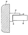
제4도는 제1도 내지 제3도의 IV 대한 상세확대도이다.4 is a detailed enlarged view of IV of FIGS. 1 to 3.
*도면의 주요부분에 대한 부호의 설명* Explanation of symbols for main parts of the drawings
3:에어크리너 4:공기닥트3: Air cleaner 4: Air Doc
5:리드밸브(reed valve) 6:배기매니포올드5: reed valve 6: exhaust manifold
7:2차공기공급도관 8:진공밸브7: Secondary air supply conduit 8: Vacuum valve
9:진공도관 10:솔레노이드밸브9: Vacuum Conduit 10: Solenoid Valve
11:올터네이터 12:제어기11: alternator 12: controller
13:릴레이 14:가동편13: Relay 14: Operation
15:접지 16:자화코일15: Earth 16: Magnetized coil
17:트랜지스터 18:접지17: Transistor 18: Ground
19:전선 20:촉매변환기19: wire 20: catalytic converter
본 발명은 화격자냉각장치에 관한 것으로, 특히 미분탄과 같은 벌크재료를 열처리 하기 위한 화격자냉각장치의 마모와 작동시의 특성을 고려한 이동프레임의 지지체에 관한 것이다.The present invention relates to a grate cooling device, and more particularly, to a support of a moving frame in consideration of wear and operation characteristics of the grate cooling device for heat-treating a bulk material such as pulverized coal.
일반적인 화격자냉각장치는 상부하우징과 하부하우징의 냉각매개체에 의해서 압력을 받으며 여러개의 화격자플레이트의 횡배열 횡단이 상기 물질의 이동방향을 가리키는 반면에 즉 상기 종배열은 최소한 부분적으로 이동이 가능하며 상기 화격자플래이트도 부분적으로 서로 겹친다. 이동 프래임워크는 화격자플래이트의 이동횡배열을 움직이는 종법과 횡법으로 이루어져 있으며 상기 이동구조의 버팀장치 중 어느 하나는 롤러위에서 움직이는 축으로 이루어져 있거나 평평한 선로위를 달리는 고리모양의 선로나 상기 언급된 축혹은 로울러 등을 대신하여 가늘고 긴 장력줄로 이루어진 이동프래임워크의 지지수단을 가지고 축을 회전시킨다.A typical grate cooling device is pressurized by the cooling medium of the upper and lower housings, while the transverse arrangement of the multiple grate plates indicates the direction of movement of the material, ie the longitudinal arrangement is at least partially movable and the grate The plates also partially overlap each other. The moving framework consists of a longitudinal and a transverse method of moving the transverse array of the grate plate, and either of the supporting structures of the moving structure consists of an axis moving on a roller or a ring-shaped track running on a flat track, The shaft is rotated with the supporting means of the moving framework composed of thin long tension strings instead of rollers or the like.
상기 물질의 이동구조를 이동시키도록 하기 위하여 앞뒤로 스트로크한다.Stroke back and forth to move the movement structure of the material.
일반적인 작용을 연속적인 화격자플레이트의 배열이 겹치는 길이에 따라서 1분당 70내지 150mm를 3내지 30번의 스트로크가 진행된다. 상기 스트로크는 편심구동기나 유압구동기에 의해서 기계적으로 일어난다.A typical action is 3 to 30 strokes, 70 to 150 mm per minute, depending on the length of the stack of continuous grate plates. The stroke is mechanically generated by an eccentric driver or a hydraulic driver.
지금까지 사용된 화격자 냉각장치의 대부분은 로울러위의 축 혹은 평평한 레일위의 사슬모양의 레일을 가지고 있는 회전축에 의해서 받쳐지는 이동프래임워크로 이루어진다.Most of the grate coolers used so far consist of a moving framework supported by a shaft on rollers or a rotating shaft with chain-shaped rails on flat rails.
이동 프레임워크의 측면유도는 로울러 혹은 레일의 플랜지에 의해서 이루어진다.Lateral induction of the moving framework is achieved by the rollers or flanges of the rails.
많은 경우에 있어서, 추가 추진형 로울러가 있으며 상기 프레임은 사선형 장력로드에 의해 더 보강될 수도 있다.In many cases, there is an additional propulsion roller and the frame may be further reinforced by an oblique tension rod.
로울러내마모, 로울러베아링, 레일에 의해 상기 이동프레임워트는 점차 저항력을 잃게 되면서 거기서부터 내려오게 된다. 약1년에 한 번쯤 상기 지지된 이동프레임워크는 재검토되거나 수정되어야만 한다.Roller abrasion, roller bearings, and rails allow the mobile frame water to gradually lose its resistance and come down from there. About once a year, the supported mobile framework should be reviewed or revised.
그러한 규칙적인 지속을 이겨내고 필요조건들을 고치기 위해서 수직에 평행하도록 배열된 긴 장력선과 상기 화격자 냉각장치의 세로면 또 상기 화격자냉각장치의 상부 하우징 부분에 부착된 내부영역에 달려 있는 상기 프레임워크가 조직내에 전개되어야 한다.In order to overcome such regular continuity and fix the requirements, the framework depends on a long tension line arranged parallel to the vertical and an inner region attached to the longitudinal surface of the grate cooling system and the upper housing portion of the grate cooling system. It must be deployed.
상기 측면유도는 하부하우징부분에 고정된 반대편플레이트를 마찰판이 사용하는 횡전파에 부착된 마찰판에 의해서 이루어진다. 게다가, 장력체인이 이동프레임워크와 하부 화격자 하우징사이의 가장 긴 거리까지 확장된다. 로울러웨어도 레일에 있어서의 이러한 장점에도 불구하고 이러한 디자인은 결국 이동프레임워크의 측면부의 안정성이 결여되었기 때문에 폐기되어 있다.The side induction is made by a friction plate attached to a transverse wave that the friction plate uses on the opposite plate fixed to the lower housing part. In addition, the tension chain extends to the longest distance between the moving framework and the lower grate housing. In spite of these advantages in rail, rollerware is also discarded because of the lack of stability in the side of the mobile framework.
상기 이동프레임워크의 나머지 견고함은 유압실린더의 반대페어를 가진 유압화격자구동기의 경우에 필요하며 그러한 상기 실린더의 작동량은 너무나 고르지 않아 반대편이 작동되지 않는 반면에 그 한쪽의 실린더가 실지로 모든 작동을 수행하게 될 수도 있으며 상기 이동프레임의 견고함은 그러한 고르지 못한 작동량을 보완해야만 한다.The remaining robustness of the moving framework is necessary for hydraulic grate actuators with opposite pairs of hydraulic cylinders, and the cylinders are not so uneven that the amount of operation of the cylinders does not work on the other side, whereas the cylinder on one side actually performs all operations. And the robustness of the moving frame must compensate for such uneven amounts of operation.
따라서, 플랜지드로울러, 추진로울러, 또는 마찰판, 혹은 상기 이동프레임외크의 기계적인 측면유도로 작동하는 것이 무엇이던지간에 내마모성에 지배를 받는다. 상기 내마모성은 화격자판배열의 열팽창한도를 첨가시키며, 상당히 큰 측면의 빈틈을 낳게 되며 따라서 상기 화격자의 전반적인 저항에 있어서의 감소를 낳는다.Thus, it is subject to abrasion resistance whether it is operating with a flanged drawer, a propulsion roller, or a friction plate, or with the mechanical side induction of the moving frame. The wear resistance adds to the thermal expansion limit of the grate plate arrangement, resulting in a fairly large gap in the side and thus a reduction in the overall resistance of the grate.
이러한 화격자저항력은 화격자냉각장치의 발전과 과거의 디자인에 있어서의 근본적인 문제가 되어 왔었다. 냉각매개체의 통로에 대한 최적의 저항력을 따라 화격자냉각장치의 품질은 저항력이 미분탄과 같은 벌크재속으로 냉각매체의 고른 분포를 보장하는 것처럼 대개 그 냉각 매체의 통로에 대한 저항력에 달려있다. (예를들자면, 케이 폰 베델과 알.와그너의 냉각화격자가 클링거냉각장치 혹은 열보완기인가? 횡유동냉각의 이론적실질적 한계. 제먼트-카크-집스 잡지37권 1984. 5, 244-247pp를 번역) 저항력은 화격자표면의 완전하고 고르게 분포된 개구에서 얻어지며 이것을 명심하며, 희격자는 각각 공기를 넣은 속이 빈 화격자 빔위에 놓여지게 될 상자모양의 화격자요소로 이루어져 발전해왔다.This grate resistance has been a fundamental problem in the development of grate cooling systems and past designs. Depending on the optimal resistance to the passage of the cooling medium, the quality of the grate cooling system usually depends on the resistance of the cooling medium to the passage, just as the resistance ensures an even distribution of the cooling medium in the bulk material such as pulverized coal. (For example, are K von Bethel and R. Wagner's cooling gratings a Klinger chiller or a heat complement? Theoretical practical limitations of transverse cooling. Zement-Kark-Giggs magazine 37, 1984. 5, 244-247pp. Resistance is obtained from the complete and evenly distributed openings of the grate surface, bearing in mind that the grateners have evolved into box-shaped grate elements that will each be placed on a hollow grate beam with air.
각각 셀레니움을 갖는 상기 속이 빈 빔과 화격자요소들은 이상적인 저항력을 보여준다. 그러나, 이것은 단지 회격자표면의 주요부분의 저항력을 구성하는 상기 속이빈 빔의 좁은 개구처럼 측면유도영역에서 전언된 바 있는 결여에 영향을 주지는 않는다. 개구가 통제되지 않고 내마모에 좌우되지 않는한 상기 저항력의 개념이 갖는 이점들은 충분히 활용될 수 없고 상기 통제는 벗어난 개구는 사슬모양의 내마모링크와 같다.The hollow beam and grate elements, each with selenium, show ideal resistance. However, this does not affect the deficiencies previously reported in the lateral induction zone, such as the narrow opening of the hollow beam, which constitutes the resistivity of the major part of the grating surface. As long as the opening is not controlled and dependent on the wear resistance, the advantages of the concept of resistance cannot be fully exploited and the opening out of control is like a chain wear resistant link.
화격자 저항력의 부족에 따른 결과로 냉각매체의 운반의 위험성은 증가하며 운반을 특히 모래분사에 의한 저항력이 있는 라이닝마모를 야기시키는 각 측면에서 관찰가능하다.As a result of the lack of grate resistance, the risk of transport of the cooling medium increases and it is observable on each side causing the transport to resist wear, especially by sand spraying.
수리운동사이의 상기 화격자의 생명은 가끔 두 측면의 빈틈중 하나에서 시작하는 내마모에 의해서 제한을 받는다.The life of the grate between the hydraulic movements is sometimes limited by abrasion resistance starting from one of the two flanks.
한 유도플랜지 또는 마찰판이 이동프레임의 경로를 더 이상 제한하지 않으면 이동화격자판과 측면판사이의 마찰은 계속되며 마모가 한쪽에서 진행되면 그 반대쪽의 빈틈은 더 커진다.If one guide flange or friction plate no longer restricts the path of the moving frame, the friction between the moving grate plate and the side plate continues, and as wear progresses from one side, the gap on the other side becomes larger.
측면틈새가 고저항력의 화격자냉각장치의 필요조건에 부합될만큼 충분히 좁게 고안될 수 있는 화격자냉각장치를 제시하기 위한 것이 본 발명의 주목적이다.It is a main object of the present invention to propose a grate cooling apparatus in which the side gap can be designed narrow enough to meet the requirements of the grating cooling apparatus of high resistance.
본 발명의 또 다른 주목적은 실질적으로 이동구조의 내구성이 없는 측면유도를 제시하는 것이다.Another object of the present invention is to present a substantially inductive side induction of the mobile structure.
본 발명의 또 하나의 주요한 목적이 있는데 특히 화격자 냉각장치가 합쳐진 속이빈 빔과 상자형의 상기 빔위의 회격자플레이트로 알려진 것을 고려할 때, 화격자판의 고정된 배열과 이동배열사이의 빈틈뿐 아니라 상기 화격자 냉각장치의 고정된 프레임과 이동빔사이의 측면틈새를 속이빈 빔에 의해 얻어지는 저항력에 맞추는 것이다.Another main object of the present invention is to consider the gap between the fixed arrangement of the grate plate and the moving arrangement, as well as the grating between the hollow beam combined with the grate cooling device and the box plate on the beam. The side clearances between the fixed frame of the grate cooling system and the moving beams are matched to the resistance obtained by the hollow beams.
상부, 하부하우징으로 이루어진 화격자냉각장치안에는 미분탄과 같은 물질의 이동방향에 대해 횡으로 배열된 화격자판의 여러개의 배열들 최소한 부분적으로 이동가능한 기구들과, 서로 부분적으로 겹쳐있는 화격자플레이트, 화격자판을 나르는 가로.세로의 빔에 의해 구성된 이동프레임, 이동프레임을 지지하기 위한 길다란 장력줄, 이러한 목적들은 본 발명에 따르면, 상기 화격자냉각장치의 수직의 세로평면에 대해 3°이상의 장력줄에 의해 가능하다. 상기 각도에 의하면, 상기 화격자(예를들면 중력)의 자증은 상기 이동프레임이 그 중앙위치에 오게 되면 균형을 찾게 되는 측면 빔 내에서의 두수평힘을 이끌어낸다.In a grate cooling system consisting of an upper and a lower housing, several arrangements of grate plates arranged laterally with respect to the movement direction of materials such as pulverized coal, at least partially movable mechanisms, grate plates and grate plates partially overlapping each other Moving frame constituted by a carrying horizontal and vertical beam, a long tension line for supporting the moving frame, these objects are possible according to the invention by a tension line of 3 ° or more with respect to the vertical longitudinal plane of the grate cooling device. . According to the angle, the suicide of the grate (e.g. gravity) leads to two horizontal forces in the side beam which are balanced when the moving frame is brought to its central position.
상기 이동프레임이 그 중앙위치에서 벗어나면서는 상기 두힘이 고르지 않게 되며 그 중앙위치에서 이탈을 유도한 어떤 힘에 반대되는 힘을 낳게 된다.As the moving frame is moved out of its central position, the two forces are uneven and produce a force that is opposite to any force that caused the deviation from the central position.
그 지지된 각도의 크기에 따라 약간의 이탈은 마찰이나 마모없이 사선으로 이동프레임을 유도할 만큼 충분히 강한 중앙힘을 생기게 한다.Depending on the size of the supported angle, slight deviations create a central force that is strong enough to guide the moving frame diagonally without friction or wear.
본 발명의 실시예에 따라 장력선을 한쪽으로만 휘인 플레이트 스프링에 의해서 생길지로 모르며, 그래서 상기 선들은 휘는 방향에 수직인 어떤 움직임에 대해서도 횡적인 빔에 대해서 볼 때 확실히 고정되어 있는 반면 단지 이동방향으로 굽어질 것이다. 플래이트 스프링과 횡빔에 의해 이루어진 상기 구조의 견고함에 따른 힘들은 장력선의 기울어짐과 이동프레임의 작동무게에 의해 야기되는 중앙의 힘을 더한다. 그러한 이동프레임의 강력한 측면유도와 함께 유압구동기조차 로드하의 단하나의 실린더를 갖고도 적용이 가능해질 것이며 또 수용가능한 것으로 여겨질 것이다.In accordance with an embodiment of the present invention the tension line may be caused by a plate spring that is bent only on one side, so that the lines are firmly fixed in the transverse beam for any movement perpendicular to the bending direction while in the direction of movement only. Will be bent. The rigidity of the structure made by the plate spring and the transverse beam adds the central force caused by the tilt of the tension line and the working weight of the moving frame. In addition to the strong lateral induction of such moving frames, even hydraulic actuators will be applicable and will be considered acceptable with a single cylinder under load.
본 발명의 또 다른 유익한 실시예에 따르면, 팽창이 장력선을 에워싸게 될 하부하우징위에 배치된 위로 기울어진 밀폐된 속이빈 팽창을 보여준다.According to another advantageous embodiment of the present invention, the upwardly tilted closed hollow expansion disposed above the lower housing where the expansion will surround the tension line is shown.
하부하우징이 약간은 모양이 이상하게 보일지라도, 더남은 실시예에 따르면, 하부하우징에 냉각매체를 제공하기 위한 관으로 이러한 하부하우징의 팽창이 작용하기 때문에 이것은 그래도 편리함이 있다. 이러한 기구덕분에 일반적으로 팬으로 사용된 어떤 것은 대게 화격자냉각장치위에 까지 뻗는 버너대에 다시 놓이게 된다. 본 발명의 이러한 목적에서 볼 때 이러한 해결책이 갖는 장점은 상기 냉각매체가 효과적으로 지속적인 온도를 갖게 되듯이 장력선의 온도조절을 개선시키는데 있다.Although the lower housing may look slightly odd in shape, according to a further embodiment, this is still convenient because this expansion of the lower housing acts as a tube for providing a cooling medium to the lower housing. Thanks to this mechanism, something commonly used as a fan is usually placed back in a burner stand that extends over the grate cooling system. The advantage of this solution for this purpose of the present invention is to improve the temperature control of the tension line as the cooling medium will effectively have a constant temperature.
열팽창에 의한 장력선의 길이의 다양성은 그래서 배제되며, 실질적으로 평평한 스트로크를 위한 넓은 써어클을 제공하는 것이 필요한 장력선의 전체적인 길이에서 볼 때, 상기 열팽창은 그렇지 않으면 견딜 수 없게 된다.The diversity of the length of the tension line by thermal expansion is thus ruled out, and in view of the overall length of the tension line where it is necessary to provide a wide circle for substantially flat strokes, the thermal expansion will otherwise be unbearable.
이하 본 발명을 첨부된 예시도면을 참조하여 상세히 설명한다.Hereinafter, the present invention will be described in detail with reference to the accompanying drawings.
제1도의 기존기술형태의 화격자냉각장치의 단면도는 회격자판(12)의 표면과 저항력있는 라이닝(10)사이까지 뻗어있는 상부화격자하우징과 화격자판(12)바닥에 까지 받치는(11) 측면과 특히 이동빔(1)의 바닥에까지 받치는 측면사이를 뻗고 있는 하부 화격자하우징을 보여준다. 간편함을 위해서 본 발명에 의해 커버된 영역뒤에 놓일 수 있는 하부하우징의 바닥뿐 아니라 상부하우징의 지붕은 화격자 냉각장치를 보여주는 도면에서 생략되었다.The cross-sectional view of the grate cooling device of the prior art form of FIG. 1 shows the side of the
제1도에서와 같이 이동프레임은 이동프레임의 측면유도를 형성하고 플랜지를 갖는 사슬모양의 레일(5) 혹은 로울러를 운반하는 축(6), 종빔(2), 여러개의 화격자판(12)을 나르는 위에서 언급한 바있는 이동빔(1)으로 이루어진다.As shown in FIG. 1, the moving frame forms a side guide of the moving frame and includes a chain-shaped
제4도에 의해서 나타내지는 세부사항 IV 는 저항력있는 측면 라이닝(10), 고정사이드보드(13), 이동화격자플레이트(12)를 보여준다. 사이드보드(13)와 상기 플레이트(12)사이에는 수직사선통이나 빈틈(14)과 수평틈 내지는 빈틈(15)이 있다.Detail IV represented by FIG. 4 shows a resistive side lining 10, a fixed
수평틈새는 주로 제시되지 않은 화격자플레이트의 고정배열과 화격자플레이트(12)의 이동배열사이에 존재하여 그 틈새(14,15)는 내마모에 따른 측량, 조립, 이탈의 내성과 열팽창을위해 필요하다. 전형적으로 이전의 측면틈새는 20mm의 크기였고 수평틈새(15)는 6mm였다. 상기 크기는 상기 디자인의 상태를 말하며 일정 작동기간이 끝나면 증가되어야만 한다.The horizontal gap is mainly between the fixed arrangement of the grate plate not shown and the moving arrangement of the
제2도 제1도에서 제시된 것보다 발전된 이전의 회격자구조의 또 다른 것을 보여주며 이동축(6)의 자리에는 가로빔(2)을 운반하는 횡빔(3)을 제시한다. 횡빔(3)은 장력선(4)을 받치고 있으며 하우징세부와 장력선(4)의 상부연결점은 나와있지 않다.FIG. 2 shows another of the former grating structure which has been developed from that shown in FIG. 1 and presents the
지지된 이동프레임은 측면으로 마찰판(7)에 의해서 유도되며 또한 지지부분(11)과 횡빔(3)사이에는 사선으로 뻗은 사선사슬(8)이 있다.The supported moving frame is laterally guided by the friction plate 7, and between the supporting
지지된 프레임은 마찰판(7)위에서 확실히 작동하고 마모된다. 또한 사슬링크는 급속히 닳기 때문에 이상적인 유도는 다소 짧은 작동이 끝나면 더 이상 존재하지 않게 된다.The supported frame is reliably operated and worn on the friction plate 7. Also, because chain links wear out rapidly, ideal induction no longer exists after rather short runs.
이전구조와는 다르게, 본 발명에 따라 고안되고 제3도에서 제시되는 실시예에는 장력선(4)이 상기 화격자 냉각장치(가상의) 수직의 세로면을 고려하여 15°fα를 이룬다. 상기각도는 이상적인 중심력으로 이동프레임의 무게의 위치를 옮기기 위하여 3내지 45°사이가 가능하다. 직선경로로부터 이탈됨으로써 횡빔에 생긴 상기 힘은 제2도의 마찰면7과 사슬8도는 제1도의 플랜지드 로울러의 기능에 이어진다.Unlike the previous structure, in the embodiment devised according to the invention and shown in FIG. 3, the tension line 4 is 15 ° fα, taking into account the vertical longitudinal plane of the grate cooling device (virtual). The angle may be between 3 and 45 ° to shift the position of the weight of the moving frame to the ideal center force. The force generated in the transverse beams by deviating from the straight path leads to the function of the flanged roller of FIG.
이동방향으로 휘고, 횡방향에 있으면서 견고하고, 횡빔(3)에 단단히 고정된 플래이트스프링처럼 장력선(4)을 유형화함으로써 장력선(4)과 횡빔(3)에 의해 이루어진 상기 조직의 견고함은 상기 장력선의 각도와 배열에 의해 생기는 중심력을 더한다. 제4도의 틈새(14,15)는 이동프레임의 사용에 의한 어떠한 방해도 없이 각각 2mm가 된다.The rigidity of the tissue formed by the tension line 4 and the
상기 틈새(14,15)는 내마모에 상관없이 2mm 의 폭을 유지하며 상기 냉각매체의 통로에 대해 틈새(14,15)의 유동저항력을 따라서 US PATENT 4 600 380 에 의해 공개된 것처럼 상기 화격자 조직으로 이미 제시된 저항력에 상응한다.The
제3도는 팽창이 장력선(4)을 둘러싸며 그위의 진행된 상기 물질을 냉각시키기 위한 화격자에 제공되는 냉각매체의 관(17)을 제공코자 연결된 하부하우징의 밀폐된 치우친 속이빈 팽창(16)을 보여준다.3 shows a closed biased
상기 냉각화격자의 작동하에서 상기 장력선(4)은 저항력있는 라이닝(10) 혹은 상부하우징의 온도를 변화시킴으로써 야기될 수 있는 열팽창에 기인한 상기 장력선의 길이의 다양성은 배제하며 사실 지속적인 상기 냉각매체의 온도에서 유지된다. 상기 제3도의 실시예는 내마모에 상관없이 가장 좁은 갭(14,15) 혹은 열팽창을 가능케한다.Under the operation of the cooling grating, the tension line 4 excludes the variety of lengths of the tension line due to thermal expansion which may be caused by varying the temperature of the
Claims (4)
Applications Claiming Priority (2)
| Application Number | Priority Date | Filing Date | Title |
|---|---|---|---|
| DEP3844493.3 | 1988-12-30 | ||
| DE3844493A DE3844493C1 (en) | 1988-12-30 | 1988-12-30 |
Publications (2)
| Publication Number | Publication Date |
|---|---|
| KR900010301A KR900010301A (en) | 1990-07-07 |
| KR0144578B1 true KR0144578B1 (en) | 1998-08-17 |
Family
ID=6370638
Family Applications (1)
| Application Number | Title | Priority Date | Filing Date |
|---|---|---|---|
| KR1019890020664A KR0144578B1 (en) | 1988-12-30 | 1989-12-30 | Coding apparatus for incinerator |
Country Status (10)
| Country | Link |
|---|---|
| US (1) | US4966548A (en) |
| EP (1) | EP0378821B1 (en) |
| JP (1) | JP2707343B2 (en) |
| KR (1) | KR0144578B1 (en) |
| AT (1) | ATE88264T1 (en) |
| CS (1) | CS275776B6 (en) |
| DD (1) | DD291136A5 (en) |
| DE (2) | DE3844493C1 (en) |
| DK (1) | DK167329B1 (en) |
| ES (1) | ES2039824T3 (en) |
Cited By (1)
| Publication number | Priority date | Publication date | Assignee | Title |
|---|---|---|---|---|
| KR100912221B1 (en) * | 2002-09-07 | 2009-08-14 | 피시아 밥콕 엔비론멘트 게엠베하 | Waste incinerating plant with combustion grates |
Families Citing this family (12)
| Publication number | Priority date | Publication date | Assignee | Title |
|---|---|---|---|---|
| DE4136934C2 (en) * | 1991-11-11 | 2001-03-29 | Deutz Ag | Chill grate cooler for cooling hot goods |
| DE4320725A1 (en) * | 1993-06-23 | 1995-01-05 | Kloeckner Humboldt Deutz Ag | Push-grating cooler for cooling hot material |
| DK171924B1 (en) * | 1993-10-06 | 1997-08-11 | Smidth & Co As F L | A cooler |
| FR2748552B1 (en) * | 1996-05-13 | 1998-06-05 | Gec Alsthom Stein Ind | HOUSEHOLD INCINERATION GRID |
| DE19633969A1 (en) * | 1996-08-22 | 1998-02-26 | Karl Von Wedel | Grid for material processing e.g. for cement production |
| US6298795B1 (en) | 1997-03-13 | 2001-10-09 | Bmh Claudius Peters Ag | Mounting device for the movable part of a cooling or heating grate |
| DE19906262A1 (en) * | 1999-02-15 | 2000-08-17 | Krupp Polysius Ag | Furnace for treating powdery material has heating conveyor which mounted on reversible drives supported by slide bearing supports top half of which is connected to bottom of drive and via slide bearing to bottom half which is fixed to floor |
| DE59906789D1 (en) | 1999-11-09 | 2003-10-02 | Peters Claudius Tech Gmbh | Sliding grate with side guide elements for the moving grate part |
| DE102007019530C5 (en) * | 2007-04-25 | 2018-01-04 | Alite Gmbh | Method and device for cooling a bulk material layer lying on a conveyor grate |
| DE102008056468B3 (en) * | 2008-11-04 | 2010-04-29 | Fuguma Gmbh Maschinenbau Und Kraftwerkstechnik | Sliding plate grating for combustion system that is utilized for combustion of e.g. recycling wood, has set of grating plates including bearing receiver that is supported in clearance-free manner |
| DE102012009511B4 (en) * | 2012-05-14 | 2013-12-19 | Outotec Oyj | Rostwagen for receiving bulk material |
| CN108981404A (en) * | 2018-08-27 | 2018-12-11 | 莱芜钢铁集团有限公司 | A kind of tune circle method of sintering circular-cooler slewing frame |
Family Cites Families (7)
| Publication number | Priority date | Publication date | Assignee | Title |
|---|---|---|---|---|
| US2764403A (en) * | 1954-10-21 | 1956-09-25 | William M Duncan | Pallets and grate bar therefor |
| GB842507A (en) * | 1957-04-09 | 1960-07-27 | Fuller Co | Horizontal heat-exchange apparatus |
| US3358385A (en) * | 1965-04-12 | 1967-12-19 | Fuller Co | Reciprocating grate conveyor with side wall damage preventing means |
| DE2658489C2 (en) * | 1976-12-23 | 1983-12-22 | Ludwig Riedhammer GmbH & Co KG, 8500 Nürnberg | Furnace for sintering magnetic ceramic materials |
| DE2930406A1 (en) * | 1979-07-26 | 1981-02-12 | Krupp Polysius Ag | SLIDING ROD |
| DE3131514C1 (en) * | 1981-08-08 | 1988-09-08 | Karl von Dipl.-Ing. Dipl.-Wirtsch.-Ing. 3057 Neustadt Wedel | Method for cooling refrigerated goods beds and stowing device for carrying out the method |
| DE3332592C1 (en) * | 1983-09-08 | 1985-05-15 | Karl von Dipl.-Ing. Dipl.-Wirtsch.-Ing. 3057 Neustadt Wedel | Grate floor composed of rust elements for bulk goods, such as cement clinker |
-
1988
- 1988-12-30 DE DE3844493A patent/DE3844493C1/de not_active Expired - Lifetime
-
1989
- 1989-12-16 AT AT89123308T patent/ATE88264T1/en not_active IP Right Cessation
- 1989-12-16 ES ES198989123308T patent/ES2039824T3/en not_active Expired - Lifetime
- 1989-12-16 EP EP89123308A patent/EP0378821B1/en not_active Expired - Lifetime
- 1989-12-16 DE DE8989123308T patent/DE58904080D1/en not_active Expired - Fee Related
- 1989-12-22 US US07/454,970 patent/US4966548A/en not_active Expired - Lifetime
- 1989-12-22 DK DK663889A patent/DK167329B1/en not_active IP Right Cessation
- 1989-12-28 DD DD89336611A patent/DD291136A5/en not_active IP Right Cessation
- 1989-12-28 CS CS897485A patent/CS275776B6/en unknown
- 1989-12-29 JP JP1344987A patent/JP2707343B2/en not_active Expired - Fee Related
- 1989-12-30 KR KR1019890020664A patent/KR0144578B1/en not_active IP Right Cessation
Cited By (1)
| Publication number | Priority date | Publication date | Assignee | Title |
|---|---|---|---|---|
| KR100912221B1 (en) * | 2002-09-07 | 2009-08-14 | 피시아 밥콕 엔비론멘트 게엠베하 | Waste incinerating plant with combustion grates |
Also Published As
| Publication number | Publication date |
|---|---|
| DD291136A5 (en) | 1991-06-20 |
| EP0378821B1 (en) | 1993-04-14 |
| CS275776B6 (en) | 1992-03-18 |
| DE58904080D1 (en) | 1993-05-19 |
| EP0378821A3 (en) | 1991-05-08 |
| JP2707343B2 (en) | 1998-01-28 |
| DE3844493C1 (en) | 1990-08-23 |
| DK663889D0 (en) | 1989-12-22 |
| DK167329B1 (en) | 1993-10-11 |
| DK663889A (en) | 1990-07-01 |
| ATE88264T1 (en) | 1993-04-15 |
| KR900010301A (en) | 1990-07-07 |
| US4966548A (en) | 1990-10-30 |
| ES2039824T3 (en) | 1993-10-01 |
| EP0378821A2 (en) | 1990-07-25 |
| JPH02272296A (en) | 1990-11-07 |
Similar Documents
| Publication | Publication Date | Title |
|---|---|---|
| KR0144578B1 (en) | Coding apparatus for incinerator | |
| KR100479429B1 (en) | Cooler for particulate material | |
| JP5009150B2 (en) | Bulk material cooler for cooling hot bulk material that you want to cool | |
| WO1995014627A1 (en) | A device for stabilizing the conveyor belt in a self-adjusting belt steering assembly | |
| DK0538760T3 (en) | Transport and transport respectively. escape chain assembly for railway construction machinery | |
| US4471704A (en) | Reciprocating grate systems for furnaces and incinerators | |
| DE3463176D1 (en) | Inclined grate for a furnace | |
| US4096809A (en) | Apparatus for compensating for thermally induced deformation of sections of grates in industrial furnaces or the like | |
| US5205100A (en) | Beam forming an expansion seal between two side-by-side grate layers with alternately fixed and mobile bars | |
| US10816268B2 (en) | Cement clinker cooler with reciprocating planks | |
| US6332410B1 (en) | Grate for incineration plants | |
| KR20060087705A (en) | Incinerator stoker | |
| EP0087531B1 (en) | Grate assembly in solid fuel combustion equipments | |
| US5259362A (en) | Sidewall guide for combustion grates | |
| US4638905A (en) | Inclined grate for furnaces | |
| RU2787695C1 (en) | Running beam of gantry crane | |
| CN107543170B (en) | Fire grate assembly | |
| RU2166151C2 (en) | Furnace | |
| RU2236499C1 (en) | Expansion joint for monorail | |
| KR200382595Y1 (en) | Incinerator stoker | |
| SU1668836A1 (en) | Grate for roasting or sintering machine | |
| SU1687535A1 (en) | Overhead conveyor for transporting and weighing half-carcasses of animals | |
| SU1065987A1 (en) | Traction linear motor | |
| GB191420810A (en) | Improvements in or relating to Travelling Chain Grates for Furnaces. |
Legal Events
| Date | Code | Title | Description |
|---|---|---|---|
| A201 | Request for examination | ||
| E701 | Decision to grant or registration of patent right | ||
| GRNT | Written decision to grant | ||
| FPAY | Annual fee payment |
Payment date: 20030415 Year of fee payment: 6 |
|
| LAPS | Lapse due to unpaid annual fee |