JPWO2017170741A1 - Power management apparatus, power management system, and power management method - Google Patents
Power management apparatus, power management system, and power management method Download PDFInfo
- Publication number
- JPWO2017170741A1 JPWO2017170741A1 JP2018509365A JP2018509365A JPWO2017170741A1 JP WO2017170741 A1 JPWO2017170741 A1 JP WO2017170741A1 JP 2018509365 A JP2018509365 A JP 2018509365A JP 2018509365 A JP2018509365 A JP 2018509365A JP WO2017170741 A1 JPWO2017170741 A1 JP WO2017170741A1
- Authority
- JP
- Japan
- Prior art keywords
- power
- storage battery
- vehicle
- control unit
- power management
- Prior art date
- Legal status (The legal status is an assumption and is not a legal conclusion. Google has not performed a legal analysis and makes no representation as to the accuracy of the status listed.)
- Granted
Links
Images


Classifications
-
- B—PERFORMING OPERATIONS; TRANSPORTING
- B60—VEHICLES IN GENERAL
- B60L—PROPULSION OF ELECTRICALLY-PROPELLED VEHICLES; SUPPLYING ELECTRIC POWER FOR AUXILIARY EQUIPMENT OF ELECTRICALLY-PROPELLED VEHICLES; ELECTRODYNAMIC BRAKE SYSTEMS FOR VEHICLES IN GENERAL; MAGNETIC SUSPENSION OR LEVITATION FOR VEHICLES; MONITORING OPERATING VARIABLES OF ELECTRICALLY-PROPELLED VEHICLES; ELECTRIC SAFETY DEVICES FOR ELECTRICALLY-PROPELLED VEHICLES
- B60L53/00—Methods of charging batteries, specially adapted for electric vehicles; Charging stations or on-board charging equipment therefor; Exchange of energy storage elements in electric vehicles
- B60L53/30—Constructional details of charging stations
- B60L53/35—Means for automatic or assisted adjustment of the relative position of charging devices and vehicles
-
- B—PERFORMING OPERATIONS; TRANSPORTING
- B60—VEHICLES IN GENERAL
- B60L—PROPULSION OF ELECTRICALLY-PROPELLED VEHICLES; SUPPLYING ELECTRIC POWER FOR AUXILIARY EQUIPMENT OF ELECTRICALLY-PROPELLED VEHICLES; ELECTRODYNAMIC BRAKE SYSTEMS FOR VEHICLES IN GENERAL; MAGNETIC SUSPENSION OR LEVITATION FOR VEHICLES; MONITORING OPERATING VARIABLES OF ELECTRICALLY-PROPELLED VEHICLES; ELECTRIC SAFETY DEVICES FOR ELECTRICALLY-PROPELLED VEHICLES
- B60L58/00—Methods or circuit arrangements for monitoring or controlling batteries or fuel cells, specially adapted for electric vehicles
- B60L58/10—Methods or circuit arrangements for monitoring or controlling batteries or fuel cells, specially adapted for electric vehicles for monitoring or controlling batteries
- B60L58/12—Methods or circuit arrangements for monitoring or controlling batteries or fuel cells, specially adapted for electric vehicles for monitoring or controlling batteries responding to state of charge [SoC]
- B60L58/14—Preventing excessive discharging
-
- H—ELECTRICITY
- H02—GENERATION; CONVERSION OR DISTRIBUTION OF ELECTRIC POWER
- H02J—CIRCUIT ARRANGEMENTS OR SYSTEMS FOR SUPPLYING OR DISTRIBUTING ELECTRIC POWER; SYSTEMS FOR STORING ELECTRIC ENERGY
- H02J3/00—Circuit arrangements for ac mains or ac distribution networks
- H02J3/28—Arrangements for balancing of the load in a network by storage of energy
- H02J3/32—Arrangements for balancing of the load in a network by storage of energy using batteries with converting means
- H02J3/322—Arrangements for balancing of the load in a network by storage of energy using batteries with converting means the battery being on-board an electric or hybrid vehicle, e.g. vehicle to grid arrangements [V2G], power aggregation, use of the battery for network load balancing, coordinated or cooperative battery charging
-
- H—ELECTRICITY
- H02—GENERATION; CONVERSION OR DISTRIBUTION OF ELECTRIC POWER
- H02J—CIRCUIT ARRANGEMENTS OR SYSTEMS FOR SUPPLYING OR DISTRIBUTING ELECTRIC POWER; SYSTEMS FOR STORING ELECTRIC ENERGY
- H02J3/00—Circuit arrangements for ac mains or ac distribution networks
- H02J3/38—Arrangements for parallely feeding a single network by two or more generators, converters or transformers
- H02J3/46—Controlling of the sharing of output between the generators, converters, or transformers
- H02J3/466—Scheduling the operation of the generators, e.g. connecting or disconnecting generators to meet a given demand
-
- H—ELECTRICITY
- H02—GENERATION; CONVERSION OR DISTRIBUTION OF ELECTRIC POWER
- H02J—CIRCUIT ARRANGEMENTS OR SYSTEMS FOR SUPPLYING OR DISTRIBUTING ELECTRIC POWER; SYSTEMS FOR STORING ELECTRIC ENERGY
- H02J7/00—Circuit arrangements for charging or depolarising batteries or for supplying loads from batteries
- H02J7/0068—Battery or charger load switching, e.g. concurrent charging and load supply
-
- Y—GENERAL TAGGING OF NEW TECHNOLOGICAL DEVELOPMENTS; GENERAL TAGGING OF CROSS-SECTIONAL TECHNOLOGIES SPANNING OVER SEVERAL SECTIONS OF THE IPC; TECHNICAL SUBJECTS COVERED BY FORMER USPC CROSS-REFERENCE ART COLLECTIONS [XRACs] AND DIGESTS
- Y02—TECHNOLOGIES OR APPLICATIONS FOR MITIGATION OR ADAPTATION AGAINST CLIMATE CHANGE
- Y02T—CLIMATE CHANGE MITIGATION TECHNOLOGIES RELATED TO TRANSPORTATION
- Y02T10/00—Road transport of goods or passengers
- Y02T10/60—Other road transportation technologies with climate change mitigation effect
- Y02T10/70—Energy storage systems for electromobility, e.g. batteries
-
- Y—GENERAL TAGGING OF NEW TECHNOLOGICAL DEVELOPMENTS; GENERAL TAGGING OF CROSS-SECTIONAL TECHNOLOGIES SPANNING OVER SEVERAL SECTIONS OF THE IPC; TECHNICAL SUBJECTS COVERED BY FORMER USPC CROSS-REFERENCE ART COLLECTIONS [XRACs] AND DIGESTS
- Y02—TECHNOLOGIES OR APPLICATIONS FOR MITIGATION OR ADAPTATION AGAINST CLIMATE CHANGE
- Y02T—CLIMATE CHANGE MITIGATION TECHNOLOGIES RELATED TO TRANSPORTATION
- Y02T10/00—Road transport of goods or passengers
- Y02T10/60—Other road transportation technologies with climate change mitigation effect
- Y02T10/7072—Electromobility specific charging systems or methods for batteries, ultracapacitors, supercapacitors or double-layer capacitors
-
- Y—GENERAL TAGGING OF NEW TECHNOLOGICAL DEVELOPMENTS; GENERAL TAGGING OF CROSS-SECTIONAL TECHNOLOGIES SPANNING OVER SEVERAL SECTIONS OF THE IPC; TECHNICAL SUBJECTS COVERED BY FORMER USPC CROSS-REFERENCE ART COLLECTIONS [XRACs] AND DIGESTS
- Y02—TECHNOLOGIES OR APPLICATIONS FOR MITIGATION OR ADAPTATION AGAINST CLIMATE CHANGE
- Y02T—CLIMATE CHANGE MITIGATION TECHNOLOGIES RELATED TO TRANSPORTATION
- Y02T90/00—Enabling technologies or technologies with a potential or indirect contribution to GHG emissions mitigation
- Y02T90/10—Technologies relating to charging of electric vehicles
- Y02T90/12—Electric charging stations
-
- Y—GENERAL TAGGING OF NEW TECHNOLOGICAL DEVELOPMENTS; GENERAL TAGGING OF CROSS-SECTIONAL TECHNOLOGIES SPANNING OVER SEVERAL SECTIONS OF THE IPC; TECHNICAL SUBJECTS COVERED BY FORMER USPC CROSS-REFERENCE ART COLLECTIONS [XRACs] AND DIGESTS
- Y02—TECHNOLOGIES OR APPLICATIONS FOR MITIGATION OR ADAPTATION AGAINST CLIMATE CHANGE
- Y02T—CLIMATE CHANGE MITIGATION TECHNOLOGIES RELATED TO TRANSPORTATION
- Y02T90/00—Enabling technologies or technologies with a potential or indirect contribution to GHG emissions mitigation
- Y02T90/10—Technologies relating to charging of electric vehicles
- Y02T90/14—Plug-in electric vehicles
Abstract
電力管理装置は、系統から施設の負荷への電力供給を制御する電力供給制御部を備える電力管理装置であって、電力供給制御部は、車両に搭載された蓄電池が系統に電気的に接続された状態において、蓄電池の状態に関する情報を取得し、該情報と、車両の操作入力とに基づいて、蓄電池の蓄電電力を系統及び負荷の少なくとも一方に供給する。The power management device is a power management device that includes a power supply control unit that controls power supply from the grid to the facility load, and the power supply control unit includes a storage battery mounted on the vehicle and is electrically connected to the grid. In this state, information on the state of the storage battery is acquired, and the stored power of the storage battery is supplied to at least one of the system and the load based on the information and the operation input of the vehicle.
Description
本出願は、日本国特許出願2016−066828号(2016年3月29日出願)の優先権を主張するものであり、当該出願の開示全体を、ここに参照のために取り込む。 This application claims the priority of Japanese Patent Application No. 2006-0666828 (filed on Mar. 29, 2016), the entire disclosure of which is incorporated herein by reference.
本開示は、電力管理装置、電力管理システム及び電力管理方法に関する。 The present disclosure relates to a power management apparatus, a power management system, and a power management method.
従来、車両が備える蓄電装置に蓄えられたエネルギーを電力系統(以下、系統と称す。)に供給する技術が開示されている。例えば、特許文献1には、自動車の制御部が、電気モータに駆動エネルギーを供給する蓄積装置から系統への電流の流れを許容する技術が開示されている。 Conventionally, a technology for supplying energy stored in a power storage device included in a vehicle to an electric power system (hereinafter referred to as a system) has been disclosed. For example, Patent Document 1 discloses a technique in which a control unit of an automobile allows a current flow from a storage device that supplies driving energy to an electric motor to a system.
一実施形態に係る電力管理装置は、系統から施設の負荷への電力供給を制御する制御部を備える電力管理装置である。前記制御部は、車両に搭載された蓄電池が前記系統に電気的に接続された状態において、前記蓄電池の状態に関する情報を取得し、該情報と、前記車両の操作入力とに基づいて、前記蓄電池の蓄電電力を前記系統及び前記負荷の少なくとも一方に供給する。 A power management apparatus according to an embodiment is a power management apparatus including a control unit that controls power supply from a system to a load of a facility. The control unit acquires information on the state of the storage battery in a state where a storage battery mounted on the vehicle is electrically connected to the system, and based on the information and an operation input of the vehicle, the storage battery Is supplied to at least one of the grid and the load.
本開示は、上述した電力管理装置に実質的に相当するシステム及び方法としても実現し得るものであり、本開示の範囲にはこれらも包含されるものと理解されたい。 It should be understood that the present disclosure can be realized as a system and method substantially corresponding to the above-described power management apparatus, and these are also included in the scope of the present disclosure.
例えば、一実施形態に係る電力管理システムは、車両に搭載され、系統に電気的に接続可能な蓄電池と、前記系統から施設の負荷への電力供給を制御する制御部と、を備える。前記制御部は、前記蓄電池が前記系統に電気的に接続された状態において、前記蓄電池の状態に関する情報を取得し、該情報と、前記車両の操作入力とに基づいて、前記蓄電池の蓄電電力を前記系統及び前記負荷の少なくとも一方に供給する。 For example, a power management system according to one embodiment includes a storage battery that is mounted on a vehicle and can be electrically connected to a system, and a control unit that controls power supply from the system to a load of a facility. The control unit obtains information related to the state of the storage battery in a state where the storage battery is electrically connected to the system, and based on the information and the operation input of the vehicle, stores the storage power of the storage battery. Supply to at least one of the system and the load.
一実施形態に係る電力管理方法は、系統から施設への電力供給を制御する制御部を備える電力管理装置による電力管理方法である。前記電力管理方法では、車両に搭載された蓄電池が前記系統に電気的に接続された状態において、前記制御部が、前記蓄電池の状態に関する情報を取得するステップを含む。前記電力管理方法では、前記制御部が、前記取得した前記蓄電池の状態に関する情報と、前記車両の操作入力とに基づいて、前記蓄電池の蓄電電力を前記系統及び前記負荷の少なくとも一方に供給するステップを含む。 A power management method according to an embodiment is a power management method by a power management apparatus including a control unit that controls power supply from a grid to a facility. The power management method includes a step in which the control unit acquires information on the state of the storage battery in a state where the storage battery mounted on the vehicle is electrically connected to the system. In the power management method, the control unit supplies the stored power of the storage battery to at least one of the system and the load based on the acquired information on the state of the storage battery and an operation input of the vehicle. including.
車両の所有者(ユーザ)が、当日中に運転を行わないことを決定した場合に、必要に応じて車両の蓄電装置に蓄えられた電力を系統に供給できれば、系統における電力供給をより安定化させることができる。本開示に係る電力管理装置、電力管理システム及び電力管理方法によれば、系統における電力供給をより安定化させることができる。 If the vehicle owner (user) decides not to drive during the day, if the power stored in the power storage device of the vehicle can be supplied to the system as needed, the power supply in the system will be more stable Can be made. According to the power management device, the power management system, and the power management method according to the present disclosure, it is possible to further stabilize the power supply in the system.
以下、本開示の一実施形態について、図面を参照して詳細に説明する。 Hereinafter, an embodiment of the present disclosure will be described in detail with reference to the drawings.
電力管理システム100は、図1に示すように電力供給ネットワーク110と、需要家施設120(以下、施設120とする)と、車両130とを有する。図1では、説明のため、施設120及び車両130をそれぞれ1つずつ示しているが、電力管理システム100は、複数の施設120及び車両130を有する。本実施形態において、施設120は、需要家の住居(家)であるとして、以下説明する。本実施形態において、車両130は、電力を充放電可能な蓄電池132を備える電気自動車であるとして、以下説明する。
As shown in FIG. 1, the
本実施形態に係る電力管理システム100において、電力供給ネットワーク110は、施設120に電力を供給する。電力管理システム100において、車両130は、例えばケーブル等で施設120に接続されている場合、蓄電池132に充電された電力を、施設120内の配線を介して、電力供給ネットワーク110に供給することができる。電力供給ネットワーク110は、施設120を介して蓄電池132から供給された電力を、他の施設120に供給することができる。電力管理システム100は、需要家(車両130のユーザ)が施設120又は車両130から所定の操作入力を行うことで車両130を所定の期間運転しない旨の意思を表示すると、蓄電池132に充電された電力が電力供給ネットワーク110に供給される。以下、電力管理システム100を構成する各構成要素と、電力管理システム100における電力管理方法の詳細について説明する。
In the
電力供給ネットワーク110は、施設120に電力を供給する。電力供給ネットワーク110は、発電所111と、給電指令所112と、電力小売会社113と、電力管理装置150と、系統115とを有する。電力管理装置150は、電力供給制御部(デマンドレスポンス(DR:Demand Response)コントローラ)114(以下、制御部114とする)を含む。
The
発電所111は、系統115を介して施設120に供給される電力を発生させる。発電所111は、例えば水力、火力、原子力、太陽光、風力及び地熱等により発電を行う。
The
給電指令所112は、各施設120に対する電力の需給バランスを管理する。具体的には、給電指令所112は、各施設120における電力需要に応じて、施設120に電力を供給する。
The power supply command center 112 manages the power supply / demand balance for each
電力小売会社113は、各需要家と契約して、各施設120に対して電力を販売する。具体的には、電力小売会社113は、需要家との契約内容に応じて、施設120に電力を供給するサービスを提供する。電力小売会社113は、発電所111を有する電力会社に含まれていてもよく、電力会社とは別の独立した会社であってもよい。
The electric power retail company 113 contracts with each consumer and sells electric power to each
制御部114は、系統115から各施設120への電力供給を制御する。制御部114は、電力の需給バランスを予測する。例えば制御部114は、電力供給ネットワーク110が施設120に供給可能な電力(供給電力量)と、施設120において予測される消費電力量(需要電力量)とに基づいて、需要電力量を電力供給ネットワーク110から供給可能か否かを判断する。本実施形態において、供給電力量は、車両130のユーザが所定の操作入力を行った場合における、車両130の蓄電池132から系統115に供給可能な電力量を含む。制御部114は、施設120を介して、車両130の蓄電池132の状態に関する情報を取得し、供給電力量を予測する。車両130の蓄電池132の状態に関する情報は、蓄電池132の蓄電電力(残量)に関する情報を含む。制御部114は、必要に応じて、系統115に電気的に接続された蓄電池132から、系統115に電力を供給可能である。
The
制御部114は、需要電力量が供給電力量を上回ると判断した場合、需要家に対して、施設120における消費電力の削減を求める電力削減要求を通知する。電力削減要求は、例えば、需要家が所有する端末装置等に対して行われる。
When the
本実施形態において、制御部114は、系統115に供給可能な電力量を予測し、需要家の車両130が備える蓄電池132から供給可能な電力量も含めた電力の需給バランスを予測する。制御部114による電力の需給バランスの予測方法の詳細については後述する。
In the present embodiment, the
系統115は、電力を施設120に供給するための配線設備等を含む。
The
施設120は、需要家が電力を消費する施設である。施設120は、電力管理システム100において使用される機能部として、電力送受電部121と、負荷122と、パワーコンディショナ(PCS:Power Conditioning System)123と、接続インタフェース(I/F:Interface)124と、通信部125と、施設側制御部126(以下、制御部126とする)と、表示部127とを備える。
The
電力送受電部121は、系統115から供給される電力を取得する。電力送受電部121は、車両130が施設120に接続されている場合、蓄電池132の電力を系統115に供給できる。
The power transmission /
負荷122は、電力を消費する電力負荷であり、例えば家庭内で使用されるエアコン、電子レンジ、テレビ等の各種電器製品、及び、商工業施設で使用される空調機、照明器具等の機械、照明設備等を含む。
The
PCS123は、系統115から供給される交流の電力と、蓄電池132において充放電される直流の電力との変換を行う。この電力の変換は、一般的なインバータの機能によって行うことができる。PCS123は、蓄電池132の充電を行う場合、系統115から供給される交流の電力を直流の電力に変換して、車両130に供給する。PCS123は、蓄電池132に充電された電力を系統115に供給する場合、蓄電池132から供給される直流の電力を交流の電力に変換して、系統115に供給する。
The
接続I/F124は、車両130が備える接続I/F131と接続されることにより、車両130を施設120に接続するためのインタフェースである。施設120と車両130とは、例えば施設120における充電ケーブルの充電プラグを、車両130のインレットに接続する(差し込む)ことにより、互いに接続される。
The connection I /
通信部125は、ネットワーク140を介して制御部114と通信を行うことにより、各種情報の送受信を行う。通信部125は、例えば制御部114が電力の需給バランスを予測するために必要な各種情報を、制御部114に送信する。通信部125が制御部114に送信する情報の一例については、後述する。通信部125は、例えば、系統115から施設120への供給電力及び施設120から系統115への供給電力を計測可能なスマートメータと一体として構成されていてもよい。
The
制御部126は、施設120内の各機能ブロックを制御及び管理するプロセッサである。制御部126は、例えば、負荷122を構成する各機器の動作状態及び電力消費状態(電力消費量)を管理する。
The
表示部127は、液晶ディスプレイ、有機ELディスプレイ、又は無機ELディスプレイ等の周知のディスプレイにより構成される表示デバイスである。表示部127は、制御部126から取得した出力内容に関する情報に基づいて、電力管理システム100に関連する各種情報を表示する。表示部127は、例えばタッチスクリーンにより構成されている場合には、需要家からの操作入力を受け付ける入力部としても機能する。
The display unit 127 is a display device configured by a known display such as a liquid crystal display, an organic EL display, or an inorganic EL display. The display unit 127 displays various types of information related to the
車両130は、需要家が乗車して走行可能な車両であり、例えば電気自動車である。車両130は、接続I/F131と、蓄電池132と、車両側制御部133(以下、制御部133とする)と、運転操作部134と、表示部135と、モータ136と、電子制御ユニット(ECU:Electric Control Unit)137とを備える。
The
接続I/F131は、施設120の接続I/F124と接続されることにより、車両130を施設120に接続するインタフェースである。車両130は、施設120に接続された場合、接続I/F131を介して、車両130に関する各種情報(車両情報)を、施設120に送信する。例えば、車両130は、車両130の走行距離に関する情報及び蓄電池132の状態に関する情報を施設120に送信する。
The connection I /
蓄電池132は、リチウムイオン電池又はニッケル水素電池等の蓄電池により構成される。蓄電池132は、充電された電力を放電することにより、モータ136に電力を供給できる。蓄電池132は、施設120を介して系統115から供給される電力を充電可能である。蓄電池132は、充電された電力を放電することにより、施設120を介して、系統115に電力を供給できる。
The
制御部133は、蓄電池132における充放電を制御するプロセッサである。従って、上述の蓄電池132における充放電は、制御部133により制御される。制御部133は、接続I/F131を介して施設120と通信を行い、各種情報を送受信する。例えば、制御部133は、施設120に、蓄電池132の状態に関する情報を送信する。
The
運転操作部134は、需要家が車両130を運転操作するための運転用インタフェースであり、例えばステアリングホイール及びシフトレバー等を含む。
The driving operation unit 134 is a driving interface for a consumer to drive the
表示部135は、液晶ディスプレイ、有機ELディスプレイ、又は無機ELディスプレイ等の周知のディスプレイにより構成される表示デバイスである。表示部135には、車両130の運転状況及び車両130に関する各種情報が表示される。表示部135には、電力管理システム100に関連する各種情報が表示される。
The
表示部135は、例えばタッチスクリーンにより構成されている。この場合、表示部135は、需要家からの操作入力を受け付ける入力部としても機能する。表示部135は、例えばヘッドアップディスプレイ(HUD:Head-Up Display)であってもよい。HUDは、車両130のフロントウィンドシールドに画像を投射し、投射された画像の反射光を、虚像として需要家に視認させるものである。
The
モータ136は、蓄電池132から供給される電力に基づき駆動する、車両130の動力である。
The
ECU137は、車両130の全体を制御する。すなわち、ECU137は、表示部135、モータ136、及び、車両130が備える図示しない他の被制御装置を制御する。ここでいう他の被制御装置は、例えば、トランスミッション、カーエアコンディショナ、パワーウィンドウ、カーナビゲーションシステム、カーオーディオ等をはじめ、車両130に関連して使用される任意の装置である。
The
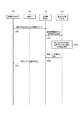
次に、電力管理システム100における、制御部114による電力の需給バランスの予測処理及びこれに関連する制御について、図2を用いて説明する。
Next, the power supply / demand balance prediction process by the
図2のシーケンス図の開始時点において、施設120と車両130とは接続されていない。
At the start of the sequence diagram of FIG. 2, the
まず、制御部114は、施設120における所定時間後の電力需要量を予測する(ステップS101)。制御部114は、例えば、図示しない記憶部内に記憶された、施設120における過去の消費電力に関する情報に基づいて、需要電力量の予測値を算出する。
First, the
制御部114は、車両130の蓄電池132が系統115に供給可能な電力量を予測する(ステップS102)。制御部114は、蓄電池132が系統115に供給可能な電力量を、例えば一日ごとに予測する。制御部114は、例えば、ネットワーク140を介して施設120から受信した車両130の過去の走行記録に基づいて予測を行う。制御部114は、例えば、需要家が加入している自動車保険の契約内容を取得可能な場合には、当該契約内容に基づいた走行距離等に応じて、予測を行ってもよい。
The
図3に示すように、制御部114は、蓄電池132の蓄電電力(残量)を、「走行用」と「系統用」とで予測する。ここで、「走行用」は、蓄電池132の蓄電可能な電力のうち、需要家が車両130を走行させるために消費するための電力量の予測値を示す。「系統用」は、蓄電池132の蓄電可能な電力のうち、「走行用」以外に消費可能な電力量の予測値を示す。「系統用」の電力量は、需要家が車両130の走行のために使用せず、同日中に消費しないため、必要に応じて蓄電池132が放電することにより系統115に供給可能な電力量である。
As shown in FIG. 3, the
図3に示す例では、蓄電池132の最大の蓄電容量は、24kWhである。図3は、一例として、6月1日(日)から6月4日(水)までの予測結果を示している。また、図3に示す例では、各日の午前0時を基準として、すなわち午前0時において最大の蓄電容量まで充電された状態を想定して、30分ごとの残量の変化が記載されている。
In the example shown in FIG. 3, the maximum storage capacity of the
図3に示す例では、6月1日(日)は、「走行用」として、蓄電池132の最大の蓄電容量である24kWhが割り当てられており、「系統用」としては、電力が割り当てられていない。これは、例えば過去の車両130の走行記録に基づき、日曜日には、「系統用」の電力が残らない可能性があるため、制御部114が、蓄電池132の充電電力量の全体を「走行用」に割り当てていることを示している。図3には、6月1日(日)の残容量の欄において、「走行用」の電力として4.5kWhと記載されている。これは、制御部114が、例えば日曜日の終了時において、蓄電池132に残存する容量が4.5kWhであると予測したことを示している。
In the example shown in FIG. 3, 24 kWh, which is the maximum storage capacity of the
次に、図3に示す表の6月2日(月)の欄を参照すると、「走行用」の電力として5.0kWh、「系統用」の電力として19.0kWhがそれぞれ割り当てられている。これは、例えば過去の車両130の走行記録に基づき、月曜日には、「走行用」の電力が5.0kWh確保されていれば、需要家が車両130を走行させるには十分であると、制御部114が、予測していることを示している。そのため、制御部114は、19.0kWhの電力が「系統用」として使用することが可能であると予測している。図3に示す例では、制御部114は、「走行用」として割り当てた5.0kWhの電力のうち、6月2日(月)の終了時点で、1.8kWhが残ると予測している。6月3日(火)及び4日(水)についても、おおよそ6月1日(月)と同様の予測結果が出力されている。
Next, referring to the column of June 2 (Monday) in the table shown in FIG. 3, 5.0 kWh is allocated as “traveling” power and 19.0 kWh is allocated as “grid” power. This is based on, for example, past travel records of the
制御部114が、このように一日ごとに、30分ごとの「走行用」及び「系統用」の蓄電電力の変化を予測することにより、電力管理システム100における電力の需給バランスの予測精度を向上させることができる。
Thus, the
施設120の制御部126は、例えば定期的に、通信部125から施設120における電力需要に関する情報を、制御部114に送信する(ステップS103)。施設120における電力需要に関する情報は、例えば所定時間後において施設120で消費されると予想される電力量である。施設120における電力需要に関する情報は、例えば、制御部126が、現在の施設120における消費電力量に基づいて生成する。
For example, the
制御部114は、制御部126から受信した電力需要に関する情報に基づき、ステップS101で算出した電力需要量の予測値を更新する(ステップS104)。
The
そして、制御部114は、算出(更新)した電力需要量の予測値を、施設120の制御部126に送信する(ステップS105)。制御部114は、例えば定期的に電力需要の予測値を送信してもよく、または、例えば制御部126からの電力需要に関する情報を取得するたびに、電力需要の予測値を送信してもよい。
Then, the
電力管理システム100において、需要家が車両130を施設120に接続すると、接続I/F124は、制御部126に車両130が施設120に接続されたことを示す接続通知を送信する(ステップS106)。
In the
制御部126は、接続通知を受信すると、接続I/F124を介して、制御部133に、車両130に関する情報の提供要求を送信する(ステップS107)。
Upon receiving the connection notification, the
制御部133は、制御部126からの提供要求に対する応答として、車両情報を、制御部126に送信する(ステップS108)。
The
制御部126は、制御部133から取得した車両情報を、制御部114に送信する(ステップS109)。
The
制御部114は、制御部126から車両情報を取得すると、ステップS102で算出した、車両130の蓄電池132が系統115に供給可能な電力量の予測値を更新する(ステップS110)。このとき、制御部114は、例えば、車両情報に含まれる車両130の蓄電池132の状態に基づき、必要に応じて、例えば図3に示した予測結果に関する情報を修正する。
When acquiring the vehicle information from the
制御部114は、更新した蓄電池132が系統115に供給可能な電力量の予測値を、制御部126に送信する(ステップS111)。
The
制御部126は、制御部114から取得した、蓄電池132が系統115に供給可能な電力量の予測値を、接続I/F124を介して制御部133に送信する(ステップS112)。
The
図4に示す画面200は、例えば施設120の制御部126が、図2のステップS111によって、更新した予測値を取得した場合に、表示部127に表示される。あるいは、図4に示す画面200は、例えば車両130の制御部133が、図2のステップS112によって、更新した予測値を取得した場合に、表示部135に表示される。ここでは、表示部127及び表示部135は、入力部の機能も有しているものとして、説明する。
The
図4に示すように、画面200は、走行可能距離201と、走行推奨距離範囲202と、節電イベント203と、節電イベント協力情報204と、残量情報グラフ205と、運転終了ボタン206とが表示される。
As shown in FIG. 4, the
走行可能距離201は、車両130の蓄電池132の蓄電電力に基づいて算出される、車両130の最大走行可能距離に関する情報である。すなわち、走行可能距離201は、蓄電池132の現在の蓄電電力から、充電することなく車両130が走行可能な距離を示す。
The
走行推奨距離範囲202は、蓄電池132において「走行用」として割り当てられた電力のうち、未だ消費されていない電力に基づいて算出される、車両130の走行可能距離に関する情報である。すなわち、走行推奨距離範囲202は、「走行用」として割り当てられた電力の残量で、車両130が走行可能な距離を示す。需要家は、蓄電池132に「系統用」として割り当てられた電力が残っている限り、走行推奨距離範囲202として表示される距離を超えて車両130を走行させることが可能である。しかしながら、こうした場合、需要家は、電力管理システム100における節電の要請に協力できなくなる可能性があり、後述する報償を受け取ることができなくなる場合がある。
The recommended
節電イベント203は、制御部114が需要家に対して通知する節電の要請(依頼)に関する情報である。節電イベント203は、例えば制御部114が算出した、電力需要量の予測値及び蓄電池132が系統115に供給可能な電力量の予測値等に基づき、節電の要請が必要であると判断した場合に、施設120に対して通知する。図4に示す画面200では、一例として、節電イベント203の具体的な内容として、節電を要請する時間帯が表示されている。
The
節電イベント協力情報204は、需要家による節電イベントに対する協力状況を示す情報である。節電イベント協力情報204は、例えば毎週日曜日に初期化され、週ごとの協力状況として表示される。図4に示す画面200では、節電イベント協力情報204として、需要家が協力したことにより得た報酬と、当該報酬に応じて需要家が享受し得るメリットが表示されている。本実施形態では、報酬は、ポイントとして需要家に与えられる。需要家は獲得したポイントに応じて、例えば無料で蓄電池132を充電できる。図4に示すように、本実施形態では、報酬に応じて需要家が享受し得るメリットとして、獲得したポイントで蓄電池132を充電した場合における蓄電電力によって車両130が走行可能な距離が示されている。
The power saving
残量情報グラフ205は、蓄電池132の残量(蓄電電力)に関する情報を示すドーナツグラフである。ドーナツグラフの中央には、蓄電池132全体の残量と、「走行用」の残量と、「系統用」の残量とが、それぞれ数値として示されている。ドーナツグラフでは、蓄電池132において、「走行用」及び「系統用」にそれぞれ割り当てられた容量が表示されている。ドーナツグラフには、蓄電池132において消費した電力も表示されている。図4に示す例では、「走行用」として割り当てられた容量のうち、一部が消費されたことが示されている。
The remaining
需要家は、画面200に表示された、走行可能距離201、走行推奨距離範囲202、節電イベント203、節電イベント協力情報204及び残量情報グラフ205を閲覧することにより、電力管理システム100における各種情報を確認することができる。各種情報は、蓄電池132の残量及び節電要請の有無等である。
The consumer views various information in the
運転終了ボタン206は、需要家が、同日中に車両130を使用しない旨の意思を表示するためのボタンである。需要家は、車両130を施設120に接続した状態で、運転終了ボタン206を選択する操作をすることができる。需要家が運転終了ボタン206を選択すると、電力管理システム100において、選択した時点における蓄電池132の残量が全て系統115に供給可能な電力であると判断される。
The driving
ここでは、一例として、図5を用いて需要家が車両130の表示部135に表示された運転終了ボタン206を選択した場合について、説明する。
Here, as an example, a case where the consumer selects the
需要家が表示部135に表示された運転終了ボタン206を選択すると、制御部133は、運転終了ボタン206が選択されたことを示す運転終了通知を、車両情報とともに施設120の制御部126に送信する(ステップS201)。
When the consumer selects the driving
制御部126は、制御部133から取得した運転終了通知及び車両情報を、制御部114に送信する(ステップS202)。
The
制御部114は、車両130の蓄電池132が系統115に供給可能な電力量の予測値を更新する(ステップS203)。このとき、制御部114は、運転終了通知を取得している場合、車両130の蓄電池132の残量を、全て系統115に供給可能であると判断し、蓄電池132の残量全体を、系統115に供給可能な電力量に含めるように予測値を更新する。
The
その後のステップS204及びステップS205は、図2におけるステップS111及びステップS112にそれぞれ対応するため、ここではその詳細な説明を省略する。 Subsequent Step S204 and Step S205 correspond to Step S111 and Step S112 in FIG. 2, respectively, and thus detailed description thereof is omitted here.
制御部114は、必要に応じて、例えば施設120における需要電力量が、電力供給ネットワーク110による発電電力を上回る場合には、系統115に電気的に接続された蓄電池132から系統115に電力を供給させるように制御する。蓄電池132から系統115に電力が供給されると、系統115は、蓄電池132から供給された電力を、系統115に電気的に接続された施設120に供給できる。このようにして、電力管理システム100によれば、需要家が車両130を使用しない場合に、車両130が備える蓄電池132を電力源として使用できる。そのため、電力管理システム100によれば、需要家が車両130を使用する場合には、車両130の電力を消費させない一方で、需要家が車両130を使用しない場合には、車両130の電力を消費可能にすることによって、電力供給を安定化させることができる。
The
図6に示すように画面300では、図4の画面200と比較して、運転終了ボタン206が、運転再開ボタン306に変わっている。需要家は、図4の画面200において、一度運転終了ボタン206を選択した後、再度車両130を走行させる場合には、運転再開ボタン306を選択する。需要家が運転再開ボタン306を選択すると、表示部135における表示は、画面300から画面200に切り換わり、蓄電池132の残量の一部が、「走行用」として割り当てられる。
As shown in FIG. 6, in the
図7では、図5の説明と同様に、需要家が車両130の表示部135に表示された運転再開ボタン306を選択した場合について、説明する。
In FIG. 7, as in the description of FIG. 5, a case where the customer selects the
需要家が表示部135に表示された運転再開ボタン306を選択すると、制御部133は、運転再開ボタン306が選択されたことを示す運転再開通知を、車両情報とともに施設120の制御部126に送信する(ステップS301)。
When the consumer selects the
制御部126は、制御部133から取得した運転再開通知及び車両情報を、制御部114に送信する(ステップS302)。
The
制御部114は、車両130の蓄電池132が系統115に供給可能な電力量の予測値を更新する(ステップS303)。このとき、制御部114は、運転再開通知に係る車両130の蓄電池132から、系統115への電力供給ができなくなったと判断し、車両130の蓄電池132の残量を、系統115に供給可能な電力から除いて、予測値を更新する。
The
その後のステップS304及びステップS305は、図2におけるステップS111及びステップS112にそれぞれ対応するため、ここではその詳細な説明を省略する。 Subsequent Step S304 and Step S305 correspond to Step S111 and Step S112 in FIG. 2, respectively, and thus detailed description thereof is omitted here.
このようにして、需要家は、一度運転終了ボタン206を選択した後も、例えば運転する必要が生じた場合に運転できるようになる。従って、電力管理システム100によれば、需要家の利便性が向上する。
In this way, even after the consumer has selected the driving
上記説明では、需要家が運転終了ボタン206及び運転再開ボタン306を選択することにより、それぞれ運転終了通知及び運転再開通知が制御部133から送信されると説明したが、運転終了通知及び運転再開通知は、他の操作に基づいて送信されてもよい。運転終了通知及び運転再開通知は、例えば需要家が施設120と車両130とを接続するための充電プラグにおける操作に基づいて、送信されてもよい。
In the above description, the operation end notification and the operation resumption notification are transmitted from the
需要家は、例えば図8に示す充電プラグ400を操作することにより、充電プラグ400の車両130への脱着を行う際に、同時に運転終了通知及び運転再開通知を送信させることができる。
For example, by operating the charging
充電プラグ400は、接続部401と、レバー402と、抜け防止ツメ403と、操作スイッチ404とを備える。需要家は、レバー402を操作しながら、車両130の接続I/F131(インレット)に接続部401を接続(挿入)することにより、充電プラグ400を車両130に接続する。抜け防止ツメ403は、接続I/F131に挿入された接続部401が意図せず抜けることを防止する。
The charging
図9及び図10は、充電プラグ400の上面視における操作スイッチ404を示す図である。操作スイッチ404は、例えば上面に操作しやすいように滑り止めを有する。需要家は、操作スイッチ404をスライドさせることにより、第1の位置及び第2の位置に操作する。
9 and 10 are diagrams showing the
需要家は、同日中に車両130の運転を行う場合には、操作スイッチ404が、例えば図9に示すように第1の位置となるように操作する。従って、例えば、需要家が、充電プラグ400を接続I/F131に接続した際に、操作スイッチ404を第1の位置にしたままにした場合、運転終了通知は送信されない。
When driving the
需要家は、同日中に車両130の運転を行わない場合には、操作スイッチ404が、例えば図10に示すように第2の位置となるように操作する。従って、例えば、需要家が、充電プラグ400を接続I/F131に接続した際に、操作スイッチ404を第1の位置から第2の位置に移動させることにより、運転終了通知が送信される。
When the customer does not drive the
操作スイッチ404が第2の位置にある場合に、需要家が操作スイッチ404を第1の位置に移動させると、運転再開通知が送信される。従って、需要家は、例えば車両130を運転する必要が生じた場合に、充電プラグ400を接続I/F131から外す際に、操作スイッチ404の位置を第2の位置から第1の位置に移動させることにより、運転再開通知を送信させることができる。
When the
このように、図8乃至図10を用いて説明した充電プラグ400によれば、需要家は、充電プラグ400を接続I/F131に脱着させる際に、操作スイッチ404の位置を操作することができる。操作スイッチ404の位置の操作により、自動的に運転終了通知及び運転再開通知が送信されるため、充電プラグ400によれば、利便性を向上可能である。
As described above, according to the charging
以上説明したように、制御部114は、蓄電池132の状態に関する情報を取得し、蓄電池132の状態に関する情報と、車両130のユーザからの操作入力(運転終了通知)とに基づいて、蓄電池132の蓄電電力を系統115に供給可能であると判断する。そして、需要電力が電力供給ネットワーク110による発電電力を上回る場合には、必要に応じて、系統115に電気的に接続された蓄電池132から系統115に電力を供給させるように制御する。このようにして、電力管理システム100によれば、需要家が車両130を使用しない場合には、車両130の電力を消費可能にすることによって、電力供給を安定化させることができる。
As described above, the
本開示は、上記実施形態にのみ限定されるものではなく、幾多の変形または変更が可能である。例えば、各構成部等に含まれる機能等は論理的に矛盾しないように再配置可能であり、複数の構成部等を1つに組み合わせたり、或いは分割したりすることが可能である。 The present disclosure is not limited to the above-described embodiment, and many variations or modifications are possible. For example, the functions and the like included in each component can be rearranged so as not to be logically contradictory, and a plurality of components or the like can be combined into one or divided.
例えば、上記実施形態の説明において、制御部114は、必要に応じて、系統115に電気的に接続された蓄電池132から系統115に電力を供給させるように制御すると説明した。しかし、蓄電池132の蓄電電力は、施設120内の負荷122に供給されてもよい。
For example, in the description of the above embodiment, it has been described that the
上記実施形態の説明において、電力管理システム100は、蓄電池132を備える車両130を有すると説明した。しかし、電力管理システム100は、必ずしも車両130を有していなくてもよい。電力管理システム100は、例えば蓄電池132を備える移動可能な装置を有していれば、上記実施形態と同様の電力管理方法を実現できる。
In the description of the embodiment, it has been described that the
車両130又はこれに代わる移動可能な装置は、蓄電池132とともに又は蓄電池132に代えて、発電装置を備えていてもよい。この場合、制御部114は、発電装置が発電した電力を系統115に供給することができる。発電装置を備える車両の例として、例えば、燃料電池自動車等が挙げられる。
The
上記実施形態において、施設120が需要家の住居であるとして説明したが、施設120は、必ずしも需要家の住居でなくてもよい。施設120は、例えば会社であってもよい。この場合、車両130のユーザは、例えば出勤後に車両130を会社が備える充電ケーブルに接続して、蓄電池132の蓄電電力を系統115に供給可能にすることができる。
In the above-described embodiment, the
100 電力管理システム
110 電力供給ネットワーク
111 発電所
112 給電指令所
113 電力小売会社
114 電力供給制御部
115 系統(電力系統)
120 施設
121 電力送受電部
122 負荷
123 パワーコンディショナ(PCS)
124、131 接続インタフェース
125 通信部
126 施設側制御部
127 表示部
130 車両
132 蓄電池
133 車両側制御部
134 運転操作部
135 表示部
136 モータ
137 ECU
140 ネットワーク
150 電力管理装置
200、300 画面
201 走行可能距離
202 走行推奨距離範囲
203 節電イベント
204 節電イベント協力情報
205 残量情報グラフ
206 運転終了ボタン
306 運転再開ボタン
400 充電プラグ
401 接続部
402 レバー
403 抜け防止ツメ
404 操作スイッチDESCRIPTION OF
120
124, 131
Claims (15)
前記制御部は、車両に搭載された蓄電池が前記系統に電気的に接続された状態において、前記蓄電池の状態に関する情報を取得し、該情報と、前記車両の操作入力とに基づいて、前記蓄電池の蓄電電力を前記系統及び前記負荷の少なくとも一方に供給する、
電力管理装置。A power management device including a control unit that controls power supply from a grid to a facility load,
The control unit acquires information on the state of the storage battery in a state where a storage battery mounted on the vehicle is electrically connected to the system, and based on the information and an operation input of the vehicle, the storage battery Supplying the stored power to at least one of the grid and the load,
Power management device.
前記系統から施設の負荷への電力供給を制御する制御部と、を備え、
前記制御部は、前記蓄電池が前記系統に電気的に接続された状態において、前記蓄電池の状態に関する情報を取得し、該情報と、前記車両の操作入力とに基づいて、前記蓄電池の蓄電電力を前記系統及び前記負荷の少なくとも一方に供給する、
電力管理システム。A storage battery mounted on the vehicle and electrically connectable to the system;
A control unit for controlling power supply from the system to the load of the facility,
The control unit obtains information related to the state of the storage battery in a state where the storage battery is electrically connected to the system, and based on the information and the operation input of the vehicle, stores the storage power of the storage battery. Supplying at least one of the system and the load;
Power management system.
車両に搭載された蓄電池が前記系統に電気的に接続された状態において、
前記制御部が、前記蓄電池の状態に関する情報を取得するステップと、
前記情報と、前記車両の操作入力とに基づいて、前記蓄電池の蓄電電力を前記系統及び前記負荷の少なくとも一方に供給するステップと
を含む、電力管理方法。A power management method by a power management device comprising a control unit for controlling power supply from a grid to a facility load,
In a state where the storage battery mounted on the vehicle is electrically connected to the system,
The control unit obtaining information on the state of the storage battery; and
A method of managing power, comprising: supplying stored power of the storage battery to at least one of the system and the load based on the information and an operation input of the vehicle.
The power management method according to any one of claims 11 to 14, wherein the information related to the state of the storage battery includes information related to stored power of the storage battery.
Applications Claiming Priority (3)
| Application Number | Priority Date | Filing Date | Title |
|---|---|---|---|
| JP2016066828 | 2016-03-29 | ||
| JP2016066828 | 2016-03-29 | ||
| PCT/JP2017/013015 WO2017170741A1 (en) | 2016-03-29 | 2017-03-29 | Power management apparatus, power management system, and power management method |
Publications (2)
| Publication Number | Publication Date |
|---|---|
| JPWO2017170741A1 true JPWO2017170741A1 (en) | 2019-01-31 |
| JP6639646B2 JP6639646B2 (en) | 2020-02-05 |
Family
ID=59964623
Family Applications (1)
| Application Number | Title | Priority Date | Filing Date |
|---|---|---|---|
| JP2018509365A Active JP6639646B2 (en) | 2016-03-29 | 2017-03-29 | Power management apparatus, power management system, and power management method |
Country Status (5)
| Country | Link |
|---|---|
| US (1) | US11230204B2 (en) |
| EP (1) | EP3439130A4 (en) |
| JP (1) | JP6639646B2 (en) |
| CN (1) | CN108886255B (en) |
| WO (1) | WO2017170741A1 (en) |
Families Citing this family (10)
| Publication number | Priority date | Publication date | Assignee | Title |
|---|---|---|---|---|
| JP7013864B2 (en) * | 2017-12-28 | 2022-02-01 | トヨタ自動車株式会社 | automobile |
| JP2019131112A (en) * | 2018-02-01 | 2019-08-08 | 本田技研工業株式会社 | Vehicle control system, vehicle control method, and program |
| JP6913114B2 (en) * | 2019-01-17 | 2021-08-04 | 本田技研工業株式会社 | Controls and programs |
| DE112019006669T5 (en) * | 2019-01-17 | 2021-10-14 | Honda Motor Co., Ltd. | CAPACITY CONTROL DEVICE AND PROGRAM |
| JP6874026B2 (en) * | 2019-01-17 | 2021-05-19 | 本田技研工業株式会社 | Power transmission / reception management device and program |
| JP7108552B2 (en) * | 2019-01-25 | 2022-07-28 | 本田技研工業株式会社 | Management device, management method, and program |
| JP2021149331A (en) * | 2020-03-17 | 2021-09-27 | トヨタ自動車株式会社 | Electric power trading system and charging/discharging device for electric vehicle |
| JP7474623B2 (en) * | 2020-03-27 | 2024-04-25 | 本田技研工業株式会社 | Power Calculation Device |
| WO2023170932A1 (en) * | 2022-03-11 | 2023-09-14 | 本田技研工業株式会社 | Battery management system and battery management method |
| WO2023170931A1 (en) * | 2022-03-11 | 2023-09-14 | 本田技研工業株式会社 | Battery management system, and battery management method |
Citations (7)
| Publication number | Priority date | Publication date | Assignee | Title |
|---|---|---|---|---|
| JPH10271694A (en) * | 1997-03-24 | 1998-10-09 | Nissan Motor Co Ltd | Charging/discharging system of secondary battery |
| JP2010088147A (en) * | 2008-09-29 | 2010-04-15 | Osaka Gas Co Ltd | Power supply and demand system |
| JP2012023797A (en) * | 2010-07-12 | 2012-02-02 | Tokyo Metropolitan Univ | Power distribution device, power distribution program, power distribution system, and power distribution method |
| WO2012017937A1 (en) * | 2010-08-05 | 2012-02-09 | 三菱自動車工業株式会社 | Power demand-and-supply equalization system |
| US20120157083A1 (en) * | 2010-12-16 | 2012-06-21 | General Motors Llc | System and method for providing discharge authorization to a battery-powered vehicle via a telematics system |
| JP2015015800A (en) * | 2013-07-03 | 2015-01-22 | パナソニックIpマネジメント株式会社 | Control device, and power management system |
| JP2015220862A (en) * | 2014-05-16 | 2015-12-07 | トヨタ自動車株式会社 | Power management system |
Family Cites Families (25)
| Publication number | Priority date | Publication date | Assignee | Title |
|---|---|---|---|---|
| ES2266823T3 (en) | 2002-01-24 | 2007-03-01 | Aloys Wobben | ELECTRIC VEHICLE AS A POINT POWER SUPPLY UNIT. |
| JP4232789B2 (en) * | 2006-04-24 | 2009-03-04 | トヨタ自動車株式会社 | Stop control device and stop control method for internal combustion engine |
| JP4265629B2 (en) * | 2006-08-01 | 2009-05-20 | トヨタ自動車株式会社 | Secondary battery charge / discharge control device and hybrid vehicle equipped with the same |
| JP2008054439A (en) | 2006-08-25 | 2008-03-06 | Toyota Motor Corp | Power system |
| KR20100111658A (en) | 2007-07-26 | 2010-10-15 | 그린박스 테크놀러지 인크. | System and method for transferring electrical power between grid and vehicle |
| WO2009157342A1 (en) * | 2008-06-27 | 2009-12-30 | シャープ株式会社 | Power control system for distributing power to power demanding facilities |
| JP2011083058A (en) * | 2009-10-02 | 2011-04-21 | Panasonic Electric Works Co Ltd | Device for monitoring source of electric power supplied to storage battery in power supply system |
| US8359132B2 (en) * | 2010-06-16 | 2013-01-22 | Toyota Motor Engineering & Manufacturing North America, Inc. | System and method for optimizing use of a battery |
| US9696176B2 (en) * | 2011-01-06 | 2017-07-04 | Ford Global Technologies, Llc | Information display system and method |
| JP2013046557A (en) | 2011-08-26 | 2013-03-04 | Sharp Corp | Home discharge control device and home discharge control method |
| JP5873986B2 (en) * | 2011-09-20 | 2016-03-01 | パナソニックIpマネジメント株式会社 | Charging system, server device, and server device program |
| JP5899450B2 (en) * | 2011-11-08 | 2016-04-06 | パナソニックIpマネジメント株式会社 | Power management equipment |
| JP5919525B2 (en) | 2011-11-22 | 2016-05-18 | パナソニックIpマネジメント株式会社 | Vehicle management system |
| JP5967516B2 (en) * | 2011-11-22 | 2016-08-10 | パナソニックIpマネジメント株式会社 | Power management apparatus, power management program, and power distribution system |
| DE112012006852T5 (en) * | 2012-08-31 | 2015-06-03 | Toyota Jidosha Kabushiki Kaisha | Vehicle and control method for the vehicle |
| CN103078360B (en) * | 2012-10-29 | 2016-04-20 | 中国电力科学研究院 | Scale electric automobile cluster electric power system |
| CN103595107B (en) * | 2013-12-02 | 2015-11-11 | 国家电网公司 | Electric automobile charge-discharge control system and method |
| US20150255984A1 (en) * | 2014-03-05 | 2015-09-10 | Nissan North America, Inc. | Vehicle-to-grid system control based on state of health |
| WO2015146200A1 (en) * | 2014-03-27 | 2015-10-01 | 京セラ株式会社 | Power management system, power management method, and control device |
| WO2015145784A1 (en) * | 2014-03-27 | 2015-10-01 | Nec Corporation | Energy management method and system for energy supply system |
| US10026998B2 (en) * | 2014-05-15 | 2018-07-17 | Ford Global Technologies, Llc | Electric vehicle operation to manage battery capacity |
| CN104319853B (en) * | 2014-11-14 | 2016-08-17 | 国家电网公司 | The method of electric automobile networking, Apparatus and system |
| US9527400B2 (en) * | 2015-01-30 | 2016-12-27 | Ford Global Technologies, Llc | Smart energy management to improve electrified vehicle battery life |
| CN104753164B (en) * | 2015-04-16 | 2018-12-18 | 国网河南省电力公司开封供电公司 | A kind of V2G charging station |
| CN104701931B (en) * | 2015-04-18 | 2017-02-22 | 国家电网公司 | Discharge capacity evaluation method of mass electric automobiles |
-
2017
- 2017-03-29 JP JP2018509365A patent/JP6639646B2/en active Active
- 2017-03-29 US US16/089,355 patent/US11230204B2/en active Active
- 2017-03-29 WO PCT/JP2017/013015 patent/WO2017170741A1/en active Application Filing
- 2017-03-29 EP EP17775275.5A patent/EP3439130A4/en active Pending
- 2017-03-29 CN CN201780021392.1A patent/CN108886255B/en active Active
Patent Citations (7)
| Publication number | Priority date | Publication date | Assignee | Title |
|---|---|---|---|---|
| JPH10271694A (en) * | 1997-03-24 | 1998-10-09 | Nissan Motor Co Ltd | Charging/discharging system of secondary battery |
| JP2010088147A (en) * | 2008-09-29 | 2010-04-15 | Osaka Gas Co Ltd | Power supply and demand system |
| JP2012023797A (en) * | 2010-07-12 | 2012-02-02 | Tokyo Metropolitan Univ | Power distribution device, power distribution program, power distribution system, and power distribution method |
| WO2012017937A1 (en) * | 2010-08-05 | 2012-02-09 | 三菱自動車工業株式会社 | Power demand-and-supply equalization system |
| US20120157083A1 (en) * | 2010-12-16 | 2012-06-21 | General Motors Llc | System and method for providing discharge authorization to a battery-powered vehicle via a telematics system |
| JP2015015800A (en) * | 2013-07-03 | 2015-01-22 | パナソニックIpマネジメント株式会社 | Control device, and power management system |
| JP2015220862A (en) * | 2014-05-16 | 2015-12-07 | トヨタ自動車株式会社 | Power management system |
Also Published As
| Publication number | Publication date |
|---|---|
| CN108886255A (en) | 2018-11-23 |
| US20190111805A1 (en) | 2019-04-18 |
| CN108886255B (en) | 2021-11-23 |
| US11230204B2 (en) | 2022-01-25 |
| WO2017170741A1 (en) | 2017-10-05 |
| EP3439130A4 (en) | 2019-10-16 |
| EP3439130A1 (en) | 2019-02-06 |
| JP6639646B2 (en) | 2020-02-05 |
Similar Documents
| Publication | Publication Date | Title |
|---|---|---|
| JP6639646B2 (en) | Power management apparatus, power management system, and power management method | |
| CN105277890B (en) | Battery capacity degradation indication | |
| US8854006B2 (en) | Charge control device | |
| JP5355641B2 (en) | Power supply system | |
| US20100207772A1 (en) | Remote monitoring system for plug-in vehicle | |
| CN104859584B (en) | Power generation shutdown alarm | |
| JP5900249B2 (en) | Power supply system | |
| CN108604820B (en) | Management apparatus and control method | |
| WO2014208561A1 (en) | Charging state management method, charging state management device, and program | |
| EP3068005B1 (en) | Control device of electrical apparatus and energy management system | |
| US10703269B2 (en) | Vehicle and method of notifying charging information of vehicle | |
| JP5358696B2 (en) | Charge control device for multiple quick chargers and ordinary chargers | |
| JPWO2012017936A1 (en) | Battery information output device for power supply and demand leveling system | |
| JP2014166846A (en) | Method of power management for plug-in hybrid and electric vehicle | |
| CN111746329A (en) | Charge and discharge management system | |
| JP5673474B2 (en) | Power switching device | |
| US20180022227A1 (en) | Battery charging systems and associated methods of use | |
| WO2011103249A2 (en) | Power transfer system for a rechargeable battery | |
| WO2018180438A1 (en) | Electricity sale information notification device, electricity sale information notification method, and charging system | |
| JP2015228716A (en) | Battery management device for electric automobile | |
| CN114665461A (en) | Server and power management method | |
| CN105050850A (en) | Battery maintenance system | |
| JP2021189640A (en) | Information processing device, information processing method, and program | |
| CN112602249A (en) | Display device for displaying the system state of at least two consumers, household appliance, piece of furniture, method for operating a display device, storage medium, mobile portable terminal, and server device operating in the internet | |
| US20230128961A1 (en) | Management server and management system |
Legal Events
| Date | Code | Title | Description |
|---|---|---|---|
| A621 | Written request for application examination |
Free format text: JAPANESE INTERMEDIATE CODE: A621 Effective date: 20180907 |
|
| A131 | Notification of reasons for refusal |
Free format text: JAPANESE INTERMEDIATE CODE: A131 Effective date: 20190702 |
|
| A521 | Request for written amendment filed |
Free format text: JAPANESE INTERMEDIATE CODE: A523 Effective date: 20190829 |
|
| TRDD | Decision of grant or rejection written | ||
| A01 | Written decision to grant a patent or to grant a registration (utility model) |
Free format text: JAPANESE INTERMEDIATE CODE: A01 Effective date: 20191203 |
|
| A61 | First payment of annual fees (during grant procedure) |
Free format text: JAPANESE INTERMEDIATE CODE: A61 Effective date: 20191224 |
|
| R150 | Certificate of patent or registration of utility model |
Ref document number: 6639646 Country of ref document: JP Free format text: JAPANESE INTERMEDIATE CODE: R150 |