JP5873986B2 - Charging system, server device, and server device program - Google Patents
Charging system, server device, and server device program Download PDFInfo
- Publication number
- JP5873986B2 JP5873986B2 JP2011204900A JP2011204900A JP5873986B2 JP 5873986 B2 JP5873986 B2 JP 5873986B2 JP 2011204900 A JP2011204900 A JP 2011204900A JP 2011204900 A JP2011204900 A JP 2011204900A JP 5873986 B2 JP5873986 B2 JP 5873986B2
- Authority
- JP
- Japan
- Prior art keywords
- electric vehicle
- predetermined area
- charging
- power
- demand
- Prior art date
- Legal status (The legal status is an assumption and is not a legal conclusion. Google has not performed a legal analysis and makes no representation as to the accuracy of the status listed.)
- Active
Links
Images


Classifications
-
- H—ELECTRICITY
- H02—GENERATION; CONVERSION OR DISTRIBUTION OF ELECTRIC POWER
- H02J—CIRCUIT ARRANGEMENTS OR SYSTEMS FOR SUPPLYING OR DISTRIBUTING ELECTRIC POWER; SYSTEMS FOR STORING ELECTRIC ENERGY
- H02J3/00—Circuit arrangements for ac mains or ac distribution networks
- H02J3/003—Load forecast, e.g. methods or systems for forecasting future load demand
-
- B—PERFORMING OPERATIONS; TRANSPORTING
- B60—VEHICLES IN GENERAL
- B60L—PROPULSION OF ELECTRICALLY-PROPELLED VEHICLES; SUPPLYING ELECTRIC POWER FOR AUXILIARY EQUIPMENT OF ELECTRICALLY-PROPELLED VEHICLES; ELECTRODYNAMIC BRAKE SYSTEMS FOR VEHICLES IN GENERAL; MAGNETIC SUSPENSION OR LEVITATION FOR VEHICLES; MONITORING OPERATING VARIABLES OF ELECTRICALLY-PROPELLED VEHICLES; ELECTRIC SAFETY DEVICES FOR ELECTRICALLY-PROPELLED VEHICLES
- B60L53/00—Methods of charging batteries, specially adapted for electric vehicles; Charging stations or on-board charging equipment therefor; Exchange of energy storage elements in electric vehicles
- B60L53/30—Constructional details of charging stations
- B60L53/305—Communication interfaces
-
- B—PERFORMING OPERATIONS; TRANSPORTING
- B60—VEHICLES IN GENERAL
- B60L—PROPULSION OF ELECTRICALLY-PROPELLED VEHICLES; SUPPLYING ELECTRIC POWER FOR AUXILIARY EQUIPMENT OF ELECTRICALLY-PROPELLED VEHICLES; ELECTRODYNAMIC BRAKE SYSTEMS FOR VEHICLES IN GENERAL; MAGNETIC SUSPENSION OR LEVITATION FOR VEHICLES; MONITORING OPERATING VARIABLES OF ELECTRICALLY-PROPELLED VEHICLES; ELECTRIC SAFETY DEVICES FOR ELECTRICALLY-PROPELLED VEHICLES
- B60L53/00—Methods of charging batteries, specially adapted for electric vehicles; Charging stations or on-board charging equipment therefor; Exchange of energy storage elements in electric vehicles
- B60L53/60—Monitoring or controlling charging stations
- B60L53/63—Monitoring or controlling charging stations in response to network capacity
-
- B—PERFORMING OPERATIONS; TRANSPORTING
- B60—VEHICLES IN GENERAL
- B60L—PROPULSION OF ELECTRICALLY-PROPELLED VEHICLES; SUPPLYING ELECTRIC POWER FOR AUXILIARY EQUIPMENT OF ELECTRICALLY-PROPELLED VEHICLES; ELECTRODYNAMIC BRAKE SYSTEMS FOR VEHICLES IN GENERAL; MAGNETIC SUSPENSION OR LEVITATION FOR VEHICLES; MONITORING OPERATING VARIABLES OF ELECTRICALLY-PROPELLED VEHICLES; ELECTRIC SAFETY DEVICES FOR ELECTRICALLY-PROPELLED VEHICLES
- B60L53/00—Methods of charging batteries, specially adapted for electric vehicles; Charging stations or on-board charging equipment therefor; Exchange of energy storage elements in electric vehicles
- B60L53/60—Monitoring or controlling charging stations
- B60L53/67—Controlling two or more charging stations
-
- B—PERFORMING OPERATIONS; TRANSPORTING
- B60—VEHICLES IN GENERAL
- B60L—PROPULSION OF ELECTRICALLY-PROPELLED VEHICLES; SUPPLYING ELECTRIC POWER FOR AUXILIARY EQUIPMENT OF ELECTRICALLY-PROPELLED VEHICLES; ELECTRODYNAMIC BRAKE SYSTEMS FOR VEHICLES IN GENERAL; MAGNETIC SUSPENSION OR LEVITATION FOR VEHICLES; MONITORING OPERATING VARIABLES OF ELECTRICALLY-PROPELLED VEHICLES; ELECTRIC SAFETY DEVICES FOR ELECTRICALLY-PROPELLED VEHICLES
- B60L53/00—Methods of charging batteries, specially adapted for electric vehicles; Charging stations or on-board charging equipment therefor; Exchange of energy storage elements in electric vehicles
- B60L53/60—Monitoring or controlling charging stations
- B60L53/68—Off-site monitoring or control, e.g. remote control
-
- G—PHYSICS
- G06—COMPUTING; CALCULATING OR COUNTING
- G06Q—INFORMATION AND COMMUNICATION TECHNOLOGY [ICT] SPECIALLY ADAPTED FOR ADMINISTRATIVE, COMMERCIAL, FINANCIAL, MANAGERIAL OR SUPERVISORY PURPOSES; SYSTEMS OR METHODS SPECIALLY ADAPTED FOR ADMINISTRATIVE, COMMERCIAL, FINANCIAL, MANAGERIAL OR SUPERVISORY PURPOSES, NOT OTHERWISE PROVIDED FOR
- G06Q10/00—Administration; Management
- G06Q10/04—Forecasting or optimisation specially adapted for administrative or management purposes, e.g. linear programming or "cutting stock problem"
-
- H—ELECTRICITY
- H01—ELECTRIC ELEMENTS
- H01M—PROCESSES OR MEANS, e.g. BATTERIES, FOR THE DIRECT CONVERSION OF CHEMICAL ENERGY INTO ELECTRICAL ENERGY
- H01M10/00—Secondary cells; Manufacture thereof
- H01M10/42—Methods or arrangements for servicing or maintenance of secondary cells or secondary half-cells
- H01M10/44—Methods for charging or discharging
-
- H—ELECTRICITY
- H01—ELECTRIC ELEMENTS
- H01M—PROCESSES OR MEANS, e.g. BATTERIES, FOR THE DIRECT CONVERSION OF CHEMICAL ENERGY INTO ELECTRICAL ENERGY
- H01M10/00—Secondary cells; Manufacture thereof
- H01M10/42—Methods or arrangements for servicing or maintenance of secondary cells or secondary half-cells
- H01M10/48—Accumulators combined with arrangements for measuring, testing or indicating the condition of cells, e.g. the level or density of the electrolyte
-
- H—ELECTRICITY
- H02—GENERATION; CONVERSION OR DISTRIBUTION OF ELECTRIC POWER
- H02J—CIRCUIT ARRANGEMENTS OR SYSTEMS FOR SUPPLYING OR DISTRIBUTING ELECTRIC POWER; SYSTEMS FOR STORING ELECTRIC ENERGY
- H02J7/00—Circuit arrangements for charging or depolarising batteries or for supplying loads from batteries
- H02J7/0013—Circuit arrangements for charging or depolarising batteries or for supplying loads from batteries acting upon several batteries simultaneously or sequentially
-
- B—PERFORMING OPERATIONS; TRANSPORTING
- B60—VEHICLES IN GENERAL
- B60L—PROPULSION OF ELECTRICALLY-PROPELLED VEHICLES; SUPPLYING ELECTRIC POWER FOR AUXILIARY EQUIPMENT OF ELECTRICALLY-PROPELLED VEHICLES; ELECTRODYNAMIC BRAKE SYSTEMS FOR VEHICLES IN GENERAL; MAGNETIC SUSPENSION OR LEVITATION FOR VEHICLES; MONITORING OPERATING VARIABLES OF ELECTRICALLY-PROPELLED VEHICLES; ELECTRIC SAFETY DEVICES FOR ELECTRICALLY-PROPELLED VEHICLES
- B60L2240/00—Control parameters of input or output; Target parameters
- B60L2240/60—Navigation input
- B60L2240/62—Vehicle position
- B60L2240/622—Vehicle position by satellite navigation
-
- B—PERFORMING OPERATIONS; TRANSPORTING
- B60—VEHICLES IN GENERAL
- B60L—PROPULSION OF ELECTRICALLY-PROPELLED VEHICLES; SUPPLYING ELECTRIC POWER FOR AUXILIARY EQUIPMENT OF ELECTRICALLY-PROPELLED VEHICLES; ELECTRODYNAMIC BRAKE SYSTEMS FOR VEHICLES IN GENERAL; MAGNETIC SUSPENSION OR LEVITATION FOR VEHICLES; MONITORING OPERATING VARIABLES OF ELECTRICALLY-PROPELLED VEHICLES; ELECTRIC SAFETY DEVICES FOR ELECTRICALLY-PROPELLED VEHICLES
- B60L2240/00—Control parameters of input or output; Target parameters
- B60L2240/70—Interactions with external data bases, e.g. traffic centres
-
- B—PERFORMING OPERATIONS; TRANSPORTING
- B60—VEHICLES IN GENERAL
- B60L—PROPULSION OF ELECTRICALLY-PROPELLED VEHICLES; SUPPLYING ELECTRIC POWER FOR AUXILIARY EQUIPMENT OF ELECTRICALLY-PROPELLED VEHICLES; ELECTRODYNAMIC BRAKE SYSTEMS FOR VEHICLES IN GENERAL; MAGNETIC SUSPENSION OR LEVITATION FOR VEHICLES; MONITORING OPERATING VARIABLES OF ELECTRICALLY-PROPELLED VEHICLES; ELECTRIC SAFETY DEVICES FOR ELECTRICALLY-PROPELLED VEHICLES
- B60L2240/00—Control parameters of input or output; Target parameters
- B60L2240/80—Time limits
-
- B—PERFORMING OPERATIONS; TRANSPORTING
- B60—VEHICLES IN GENERAL
- B60L—PROPULSION OF ELECTRICALLY-PROPELLED VEHICLES; SUPPLYING ELECTRIC POWER FOR AUXILIARY EQUIPMENT OF ELECTRICALLY-PROPELLED VEHICLES; ELECTRODYNAMIC BRAKE SYSTEMS FOR VEHICLES IN GENERAL; MAGNETIC SUSPENSION OR LEVITATION FOR VEHICLES; MONITORING OPERATING VARIABLES OF ELECTRICALLY-PROPELLED VEHICLES; ELECTRIC SAFETY DEVICES FOR ELECTRICALLY-PROPELLED VEHICLES
- B60L2250/00—Driver interactions
- B60L2250/10—Driver interactions by alarm
-
- B—PERFORMING OPERATIONS; TRANSPORTING
- B60—VEHICLES IN GENERAL
- B60L—PROPULSION OF ELECTRICALLY-PROPELLED VEHICLES; SUPPLYING ELECTRIC POWER FOR AUXILIARY EQUIPMENT OF ELECTRICALLY-PROPELLED VEHICLES; ELECTRODYNAMIC BRAKE SYSTEMS FOR VEHICLES IN GENERAL; MAGNETIC SUSPENSION OR LEVITATION FOR VEHICLES; MONITORING OPERATING VARIABLES OF ELECTRICALLY-PROPELLED VEHICLES; ELECTRIC SAFETY DEVICES FOR ELECTRICALLY-PROPELLED VEHICLES
- B60L2250/00—Driver interactions
- B60L2250/14—Driver interactions by input of vehicle departure time
-
- B—PERFORMING OPERATIONS; TRANSPORTING
- B60—VEHICLES IN GENERAL
- B60L—PROPULSION OF ELECTRICALLY-PROPELLED VEHICLES; SUPPLYING ELECTRIC POWER FOR AUXILIARY EQUIPMENT OF ELECTRICALLY-PROPELLED VEHICLES; ELECTRODYNAMIC BRAKE SYSTEMS FOR VEHICLES IN GENERAL; MAGNETIC SUSPENSION OR LEVITATION FOR VEHICLES; MONITORING OPERATING VARIABLES OF ELECTRICALLY-PROPELLED VEHICLES; ELECTRIC SAFETY DEVICES FOR ELECTRICALLY-PROPELLED VEHICLES
- B60L2260/00—Operating Modes
- B60L2260/40—Control modes
- B60L2260/46—Control modes by self learning
-
- H—ELECTRICITY
- H01—ELECTRIC ELEMENTS
- H01M—PROCESSES OR MEANS, e.g. BATTERIES, FOR THE DIRECT CONVERSION OF CHEMICAL ENERGY INTO ELECTRICAL ENERGY
- H01M2220/00—Batteries for particular applications
- H01M2220/20—Batteries in motive systems, e.g. vehicle, ship, plane
-
- H—ELECTRICITY
- H02—GENERATION; CONVERSION OR DISTRIBUTION OF ELECTRIC POWER
- H02J—CIRCUIT ARRANGEMENTS OR SYSTEMS FOR SUPPLYING OR DISTRIBUTING ELECTRIC POWER; SYSTEMS FOR STORING ELECTRIC ENERGY
- H02J2310/00—The network for supplying or distributing electric power characterised by its spatial reach or by the load
- H02J2310/40—The network being an on-board power network, i.e. within a vehicle
- H02J2310/48—The network being an on-board power network, i.e. within a vehicle for electric vehicles [EV] or hybrid vehicles [HEV]
-
- Y—GENERAL TAGGING OF NEW TECHNOLOGICAL DEVELOPMENTS; GENERAL TAGGING OF CROSS-SECTIONAL TECHNOLOGIES SPANNING OVER SEVERAL SECTIONS OF THE IPC; TECHNICAL SUBJECTS COVERED BY FORMER USPC CROSS-REFERENCE ART COLLECTIONS [XRACs] AND DIGESTS
- Y02—TECHNOLOGIES OR APPLICATIONS FOR MITIGATION OR ADAPTATION AGAINST CLIMATE CHANGE
- Y02E—REDUCTION OF GREENHOUSE GAS [GHG] EMISSIONS, RELATED TO ENERGY GENERATION, TRANSMISSION OR DISTRIBUTION
- Y02E60/00—Enabling technologies; Technologies with a potential or indirect contribution to GHG emissions mitigation
- Y02E60/10—Energy storage using batteries
-
- Y—GENERAL TAGGING OF NEW TECHNOLOGICAL DEVELOPMENTS; GENERAL TAGGING OF CROSS-SECTIONAL TECHNOLOGIES SPANNING OVER SEVERAL SECTIONS OF THE IPC; TECHNICAL SUBJECTS COVERED BY FORMER USPC CROSS-REFERENCE ART COLLECTIONS [XRACs] AND DIGESTS
- Y02—TECHNOLOGIES OR APPLICATIONS FOR MITIGATION OR ADAPTATION AGAINST CLIMATE CHANGE
- Y02T—CLIMATE CHANGE MITIGATION TECHNOLOGIES RELATED TO TRANSPORTATION
- Y02T10/00—Road transport of goods or passengers
- Y02T10/60—Other road transportation technologies with climate change mitigation effect
- Y02T10/70—Energy storage systems for electromobility, e.g. batteries
-
- Y—GENERAL TAGGING OF NEW TECHNOLOGICAL DEVELOPMENTS; GENERAL TAGGING OF CROSS-SECTIONAL TECHNOLOGIES SPANNING OVER SEVERAL SECTIONS OF THE IPC; TECHNICAL SUBJECTS COVERED BY FORMER USPC CROSS-REFERENCE ART COLLECTIONS [XRACs] AND DIGESTS
- Y02—TECHNOLOGIES OR APPLICATIONS FOR MITIGATION OR ADAPTATION AGAINST CLIMATE CHANGE
- Y02T—CLIMATE CHANGE MITIGATION TECHNOLOGIES RELATED TO TRANSPORTATION
- Y02T10/00—Road transport of goods or passengers
- Y02T10/60—Other road transportation technologies with climate change mitigation effect
- Y02T10/7072—Electromobility specific charging systems or methods for batteries, ultracapacitors, supercapacitors or double-layer capacitors
-
- Y—GENERAL TAGGING OF NEW TECHNOLOGICAL DEVELOPMENTS; GENERAL TAGGING OF CROSS-SECTIONAL TECHNOLOGIES SPANNING OVER SEVERAL SECTIONS OF THE IPC; TECHNICAL SUBJECTS COVERED BY FORMER USPC CROSS-REFERENCE ART COLLECTIONS [XRACs] AND DIGESTS
- Y02—TECHNOLOGIES OR APPLICATIONS FOR MITIGATION OR ADAPTATION AGAINST CLIMATE CHANGE
- Y02T—CLIMATE CHANGE MITIGATION TECHNOLOGIES RELATED TO TRANSPORTATION
- Y02T10/00—Road transport of goods or passengers
- Y02T10/60—Other road transportation technologies with climate change mitigation effect
- Y02T10/72—Electric energy management in electromobility
-
- Y—GENERAL TAGGING OF NEW TECHNOLOGICAL DEVELOPMENTS; GENERAL TAGGING OF CROSS-SECTIONAL TECHNOLOGIES SPANNING OVER SEVERAL SECTIONS OF THE IPC; TECHNICAL SUBJECTS COVERED BY FORMER USPC CROSS-REFERENCE ART COLLECTIONS [XRACs] AND DIGESTS
- Y02—TECHNOLOGIES OR APPLICATIONS FOR MITIGATION OR ADAPTATION AGAINST CLIMATE CHANGE
- Y02T—CLIMATE CHANGE MITIGATION TECHNOLOGIES RELATED TO TRANSPORTATION
- Y02T90/00—Enabling technologies or technologies with a potential or indirect contribution to GHG emissions mitigation
- Y02T90/10—Technologies relating to charging of electric vehicles
- Y02T90/12—Electric charging stations
-
- Y—GENERAL TAGGING OF NEW TECHNOLOGICAL DEVELOPMENTS; GENERAL TAGGING OF CROSS-SECTIONAL TECHNOLOGIES SPANNING OVER SEVERAL SECTIONS OF THE IPC; TECHNICAL SUBJECTS COVERED BY FORMER USPC CROSS-REFERENCE ART COLLECTIONS [XRACs] AND DIGESTS
- Y02—TECHNOLOGIES OR APPLICATIONS FOR MITIGATION OR ADAPTATION AGAINST CLIMATE CHANGE
- Y02T—CLIMATE CHANGE MITIGATION TECHNOLOGIES RELATED TO TRANSPORTATION
- Y02T90/00—Enabling technologies or technologies with a potential or indirect contribution to GHG emissions mitigation
- Y02T90/10—Technologies relating to charging of electric vehicles
- Y02T90/14—Plug-in electric vehicles
-
- Y—GENERAL TAGGING OF NEW TECHNOLOGICAL DEVELOPMENTS; GENERAL TAGGING OF CROSS-SECTIONAL TECHNOLOGIES SPANNING OVER SEVERAL SECTIONS OF THE IPC; TECHNICAL SUBJECTS COVERED BY FORMER USPC CROSS-REFERENCE ART COLLECTIONS [XRACs] AND DIGESTS
- Y02—TECHNOLOGIES OR APPLICATIONS FOR MITIGATION OR ADAPTATION AGAINST CLIMATE CHANGE
- Y02T—CLIMATE CHANGE MITIGATION TECHNOLOGIES RELATED TO TRANSPORTATION
- Y02T90/00—Enabling technologies or technologies with a potential or indirect contribution to GHG emissions mitigation
- Y02T90/10—Technologies relating to charging of electric vehicles
- Y02T90/16—Information or communication technologies improving the operation of electric vehicles
-
- Y—GENERAL TAGGING OF NEW TECHNOLOGICAL DEVELOPMENTS; GENERAL TAGGING OF CROSS-SECTIONAL TECHNOLOGIES SPANNING OVER SEVERAL SECTIONS OF THE IPC; TECHNICAL SUBJECTS COVERED BY FORMER USPC CROSS-REFERENCE ART COLLECTIONS [XRACs] AND DIGESTS
- Y04—INFORMATION OR COMMUNICATION TECHNOLOGIES HAVING AN IMPACT ON OTHER TECHNOLOGY AREAS
- Y04S—SYSTEMS INTEGRATING TECHNOLOGIES RELATED TO POWER NETWORK OPERATION, COMMUNICATION OR INFORMATION TECHNOLOGIES FOR IMPROVING THE ELECTRICAL POWER GENERATION, TRANSMISSION, DISTRIBUTION, MANAGEMENT OR USAGE, i.e. SMART GRIDS
- Y04S10/00—Systems supporting electrical power generation, transmission or distribution
- Y04S10/12—Monitoring or controlling equipment for energy generation units, e.g. distributed energy generation [DER] or load-side generation
- Y04S10/126—Monitoring or controlling equipment for energy generation units, e.g. distributed energy generation [DER] or load-side generation the energy generation units being or involving electric vehicles [EV] or hybrid vehicles [HEV], i.e. power aggregation of EV or HEV, vehicle to grid arrangements [V2G]
Description
本発明は、電動車両に対して行う充電動作を管理する充電システム、サーバ装置、及び、サーバ装置のプログラムに関する。 The present invention relates to a charging system that manages a charging operation performed on an electric vehicle, a server device, and a program for the server device.
従来より、電動車両への充電を効率よく行う充電システムとしては、下記の特許文献1などが知られている。 Conventionally, as a charging system for efficiently charging an electric vehicle, the following Patent Document 1 is known.
この特許文献1には、住宅内の電力制御装置が、電動車両に電力を供給する場所に電動車両が到着する前に、電動車両から送信された車載バッテリの充電に関する情報と受信し、充電情報に基づいて、車載バッテリ等への充電が所定時刻までに完了するように車載バッテリ等への充電開始時刻を決定する、ことが記載されている。 In Patent Document 1, a power control device in a house receives information on charging of an in-vehicle battery transmitted from an electric vehicle before the electric vehicle arrives at a place where electric power is supplied to the electric vehicle, and charging information is received. Based on the above, it is described that the charging start time for the in-vehicle battery or the like is determined so that the charging to the in-vehicle battery or the like is completed by a predetermined time.
上述した特許文献1に記載された技術では、家庭内での電力使用ピークを抑制するものである。したがって、この特許文献1に記載された技術では、電力会社が管理しているエリア単位で電力需要を抑制するものではなかった。 The technique described in Patent Document 1 described above suppresses the power usage peak in the home. Therefore, the technique described in Patent Document 1 does not suppress power demand in units of areas managed by the power company.
そこで、本発明は、上述した実情に鑑みて提案されたものであり、所定エリア単位で電力を管理することができる充電システム、サーバ装置、及び、サーバ装置のプログラムを提供することを目的とする。 Then, this invention is proposed in view of the above-mentioned situation, and it aims at providing the charging system which can manage electric power per predetermined area, a server apparatus, and the program of a server apparatus. .
本発明の第1の態様に係る充電システムは、充電池に蓄積された電力によって駆動する電動車両との間で通信可能なサーバ装置と、前記サーバ装置との間で通信可能であって前記充電池に対する充電を制御する充電制御装置とを有する充電システムであって、前記サーバ装置は、前記電動車両の移動先を含む移動情報と当該電動車両における充電池の残量情報とを前記電動車両から受信する通信部と、前記通信部により受信された前記移動先を含む移動情報及び残量情報に基づいて所定エリアごとに前記移動先を含む前記移動情報および前記残量情報を集計し、前記所定エリアにおいて前記電動車両の充電池が充電される時間帯を推定することによって前記所定エリアの需要電力を予測する需要予測部と、前記需要予測部により予測された所定エリアの需要電力に基づいて、前記所定エリアごとの電力上限からみて充電スケジュールの変更が必要な前記所定エリアに含まれる充電制御装置にある時間帯における前記電動車両への充電動作を控えることを要求する充電スケジュール変更要求を送出するスケジュール管理部とを有し、前記充電制御装置は、前記サーバ装置から送出された充電スケジュール変更要求に応じて、前記電動車両に備えられた充電池に対する充電動作のスケジュールを変更することを特徴とするものである。
本発明の第2の態様に係るサーバ装置は、充電池に蓄積された電力によって駆動する電動車両、及び、前記電動車両に搭載された充電池に対する充電を制御する充電制御装置との間で通信可能なサーバ装置であって、前記電動車両の移動先を含む移動情報と当該電動車両における充電池の残量情報とを前記電動車両から受信する通信部と、前記通信部により受信された前記移動先を含む移動情報及び残量情報に基づいて所定エリアごとに前記移動先を含む前記移動情報および前記残量情報を集計し、前記所定エリアごとに前記電動車両の充電池が充電される時間帯を推定することによって前記所定エリアごとの需要電力を予測する需要予測部と、前記需要予測部により予測された所定エリアの需要電力に基づいて、前記所定エリアごとの電力上限からみて充電スケジュールの変更が必要な前記所定エリアに含まれる充電制御装置にある時間帯における前記電動車両への充電動作を控えることを要求する充電スケジュール変更要求を送出するスケジュール管理部とを有することを特徴とする。
本発明の第3の態様に係るサーバ装置のプログラムは、充電池に蓄積された電力によって駆動する電動車両、及び、前記電動車両に搭載された充電池に対する充電を制御する充電制御装置との間で通信可能なサーバ装置のプログラムであって、前記サーバ装置のコンピュータを、前記電動車両の移動先を含む移動情報と当該電動車両における充電池の残量情報とを前記電動車両から受信する通信部、 前記通信部により受信された前記移動先を含む移動情報及び残量情報に基づいて所定エリアごとに前記移動先を含む前記移動情報および前記残量情報を集計し、前記所定エリアごとに前記電動車両の充電池が充電される時間帯を推定することによって前記所定エリアごとの需要電力を予測する需要予測部、および前記需要予測部により予測された所定エリアの需要電力に基づいて、前記所定エリアごとの電力上限からみて充電スケジュールの変更が必要な前記所定エリアに含まれる充電制御装置にある時間帯における前記電動車両への充電動作を控えることを要求する充電スケジュール変更要求を送出するスケジュール管理部として機能させることを特徴とする。
A charging system according to a first aspect of the present invention includes a server device capable of communicating with an electric vehicle driven by electric power stored in a rechargeable battery, and the server device capable of communicating with the charging device. A charging system including a charging control device that controls charging of a battery, wherein the server device transmits movement information including a destination of the electric vehicle and remaining battery charge information in the electric vehicle from the electric vehicle. Based on movement information and remaining amount information including the movement destination received by the communication unit and the communication unit received by the communication unit, the movement information and remaining amount information including the movement destination are totaled for each predetermined area, and the predetermined amount a demand prediction unit for predicting the power demand of the given area by rechargeable battery of the electric vehicle is to estimate the time zone to be charged in the area, where it was predicted by the demand prediction unit Based on the power demand of the area, requesting to refrain from the charging operation of the electric vehicle in the time zone in the charge control device included in said predetermined area mutandis power cap viewed from charging schedule for each predetermined area A charge management device for sending a charge schedule change request, wherein the charge control device performs a charge operation on a rechargeable battery provided in the electric vehicle in response to the charge schedule change request sent from the server device. The schedule is changed.
A server device according to a second aspect of the present invention communicates between an electric vehicle driven by electric power stored in a rechargeable battery and a charge control device that controls charging of the rechargeable battery mounted on the electric vehicle. A communication unit that receives movement information including a destination of the electric vehicle and remaining battery charge information in the electric vehicle from the electric vehicle, and the movement received by the communication unit based on the movement information and remaining amount information including the above aggregates the movement information and the remaining amount information including the destination for each predetermined area, time zone rechargeable battery of the electric vehicle per the predetermined area is charged wherein a demand prediction unit for predicting the power demand for each predetermined area, based on the power demand of a predetermined area predicted by the demand prediction unit by estimating the power of each of the predetermined areas And a schedule management section as viewed from the limit sending the charging schedule change request that requests to refrain from charging to the electric vehicle in the time zone in the charge control device included in the predetermined area necessary to change the charging schedule It is characterized by that.
The program of the server apparatus which concerns on the 3rd aspect of this invention is between the electric vehicle driven with the electric power accumulate | stored in the rechargeable battery, and the charge control apparatus which controls charge with respect to the rechargeable battery mounted in the said electric vehicle. A communication unit that can communicate with the computer of the server device, from the electric vehicle, the movement information including the destination of the electric vehicle and the remaining information of the rechargeable battery in the electric vehicle. The movement information including the movement destination and the remaining amount information are totaled for each predetermined area based on the movement information including the movement destination and the remaining amount information received by the communication unit, and the electric drive is performed for each predetermined area. A demand prediction unit that predicts demand power for each predetermined area by estimating a time zone in which a rechargeable battery of the vehicle is charged , and is predicted by the demand prediction unit Based on the demand power of the predetermined area, the charging operation to the electric vehicle in the time zone in the charge control device included in the predetermined area that needs to be changed from the upper limit of power for each predetermined area is refrained It is made to function as a schedule management part which sends out the charge schedule change request which requests | requires.
本発明の第4の態様に係る充電システムは、充電池に蓄積された電力によって駆動する電動車両との間で通信可能なサーバ装置と、前記サーバ装置との間で通信可能であって前記充電池に対する充電を制御する充電制御装置とを有する充電システムであって、前記サーバ装置は、前記電動車両の移動情報と当該電動車両における充電池の残量情報とを前記電動車両から受信する通信部と、前記通信部により受信された移動情報及び残量情報に基づいて所定エリアの需要電力を予測する需要予測部と、前記需要予測部により予測された所定エリアの需要電力に基づいて、当該所定エリアに含まれる充電制御装置に充電スケジュール変更要求を送出するスケジュール管理部とを有し、 前記充電制御装置は、前記サーバ装置から送出された充電スケジュール変更要求に応じて、前記電動車両に備えられた充電池に対する充電動作のスケジュールを変更し、前記スケジュール管理部は、前記所定エリアの電力消費量を取得し、取得された電力消費量と前記需要予測部により予測された当該所定エリアにおける需要電力とを比較して一致度を算出し、前記需要予測部は、前記スケジュール管理部により算出された一致度が所定値よりも低い場合に、前記移動情報及び残量情報に基づく所定エリアにおける需要電力の予測を再度行い、 前記スケジュール管理部は、前記需要予測部より再度行われた予測結果としての需要電力に基づいて、当該所定エリアに含まれる充電制御装置に充電スケジュール変更要求を送出することを特徴とする。 A charging system according to a fourth aspect of the present invention includes a server device capable of communicating with an electric vehicle driven by electric power stored in a rechargeable battery, and the server device capable of communicating with the charging device. A charging system including a charging control device that controls charging of a battery, wherein the server device receives from the electric vehicle movement information of the electric vehicle and remaining information of a rechargeable battery in the electric vehicle. A demand prediction unit that predicts demand power in a predetermined area based on the movement information and remaining amount information received by the communication unit, and the predetermined power based on the demand power in the predetermined area predicted by the demand prediction unit. A schedule management unit that sends a charge schedule change request to a charge control device included in the area, wherein the charge control device sends a charge schedule sent from the server device. In response to the joule change request, the schedule of the charging operation for the rechargeable battery provided in the electric vehicle is changed, the schedule management unit acquires the power consumption of the predetermined area, and the acquired power consumption and the Comparing the demand power in the predetermined area predicted by the demand prediction unit to calculate the coincidence, the demand prediction unit, when the coincidence calculated by the schedule management unit is lower than a predetermined value, The demand power in the predetermined area is predicted again based on the movement information and the remaining amount information, and the schedule management unit is included in the predetermined area based on the power demand as a prediction result performed again by the demand prediction unit. A charge schedule change request is sent to the charge control device.
本発明の第5の態様に係る充電システムは、第4の態様に係る充電システムに対し、前記スケジュール管理部は、前記一致度に基づいて、前記所定エリアにおける充電スケジュール変更要求の生成処理を学習することを特徴とする。 In the charging system according to the fifth aspect of the present invention, in the charging system according to the fourth aspect, the schedule management unit learns the generation process of the charging schedule change request in the predetermined area based on the degree of coincidence. It is characterized by doing.
本発明の第6の態様に係るサーバ装置は、充電池に蓄積された電力によって駆動する電動車両、及び、前記電動車両に搭載された充電池に対する充電を制御する充電制御装置との間で通信可能なサーバ装置であって、前記電動車両の移動情報と当該電動車両における充電池の残量情報とを前記電動車両から受信する通信部と、前記通信部により受信された移動情報及び残量情報に基づいて所定エリアの需要電力を予測する需要予測部と、前記需要予測部により予測された所定エリアの需要電力に基づいて、当該所定エリアに含まれる充電制御装置に充電スケジュール変更要求を送出するスケジュール管理部とを有し、前記スケジュール管理部は、前記所定エリアの電力消費量を取得し、取得された電力消費量と前記需要予測部により予測された当該所定エリアにおける需要電力とを比較して一致度を算出し、前記需要予測部は、前記スケジュール管理部により算出された一致度が所定値よりも低い場合に、前記移動情報及び残量情報に基づく所定エリアにおける需要電力の予測を再度行い、前記スケジュール管理部は、前記需要予測部より再度行われた予測結果としての需要電力に基づいて、当該所定エリアに含まれる充電制御装置に充電スケジュール変更要求を送出することを特徴とする。
本発明の第7の態様に係るサーバ装置は、第6の態様に係るサーバ装置に対し、前記スケジュール管理部は、前記一致度に基づいて、前記所定エリアにおける充電スケジュール変更要求の生成処理を学習することを特徴とする
A server device according to a sixth aspect of the present invention communicates between an electric vehicle driven by electric power stored in a rechargeable battery and a charge control device that controls charging of the rechargeable battery mounted on the electric vehicle. And a communication unit that receives the movement information of the electric vehicle and the remaining amount information of the rechargeable battery in the electric vehicle from the electric vehicle, and the movement information and the remaining amount information received by the communication unit. Based on the demand prediction unit that predicts the demand power in the predetermined area based on the demand, and based on the demand power in the predetermined area predicted by the demand prediction unit, a charge schedule change request is sent to the charge control device included in the predetermined area possess a schedule manager, the schedule management unit acquires the power consumption of the given area, is predicted by the demand prediction unit and the acquired power consumption The demand prediction unit compares the demand power in the predetermined area to calculate the degree of coincidence, and the demand prediction unit, when the degree of coincidence calculated by the schedule management unit is lower than a predetermined value, Based on demand power as a prediction result re-executed by the demand prediction unit, the schedule management unit changes the charging schedule to the charge control device included in the predetermined area. It is characterized by sending a request .
According to a seventh aspect of the present invention, in the server device according to the sixth aspect, the schedule management unit learns a charging schedule change request generation process in the predetermined area based on the degree of coincidence. It is characterized by
本発明の第8の態様に係るサーバ装置のプログラムは、充電池に蓄積された電力によって駆動する電動車両、及び、前記電動車両に搭載された充電池に対する充電を制御する充電制御装置との間で通信可能なサーバ装置のプログラムであって、前記サーバ装置のコンピュータを、前記電動車両の移動情報と当該電動車両における充電池の残量情報とを前記電動車両から受信する通信部、前記通信部により受信された移動情報及び残量情報に基づいて当該移動情報に含まれる移動先を含む所定エリアの需要電力を予測する需要予測部、および前記需要予測部により予測された所定エリアの需要電力に基づいて、当該所定エリアに含まれる充電制御装置に充電スケジュール変更要求を送出するスケジュール管理部として機能させ、前記スケジュール管理部は、前記所定エリアの電力消費量を取得し、取得された電力消費量と前記需要予測部により予測された当該所定エリアにおける需要電力とを比較して一致度を算出し、前記需要予測部は、前記スケジュール管理部により算出された一致度が所定値よりも低い場合に、前記移動情報及び残量情報に基づく所定エリアにおける需要電力の予測を再度行い、前記スケジュール管理部は、前記需要予測部より再度行われた予測結果としての需要電力に基づいて、当該所定エリアに含まれる充電制御装置に充電スケジュール変更要求を送出することを特徴とする。
本発明の第9の態様に係るサーバ装置のプログラムは、第8の態様に係るサーバ装置のプログラムに対し、前記スケジュール管理部は、前記一致度に基づいて、前記所定エリアにおける充電スケジュール変更要求の生成処理を学習することを特徴とする。
The program of the server apparatus which concerns on the 8th aspect of this invention is between the electric vehicle driven with the electric power accumulate | stored in the rechargeable battery, and the charge control apparatus which controls charge with respect to the rechargeable battery mounted in the said electric vehicle. A communication unit that can communicate with the computer of the server device, the communication unit receiving movement information of the electric vehicle and remaining information of a rechargeable battery in the electric vehicle, the communication unit the power demand of a predetermined area that is predicted demand prediction unit predicts the power demand of a predetermined area including the destination included in the movement information on the basis of the movement information and the balance information received, and by the demand prediction unit by based on, to function as a schedule management unit for sending a charging schedule change request to the charge control device included in the predetermined area, the schedule The management unit acquires the power consumption of the predetermined area, compares the acquired power consumption with the demand power in the predetermined area predicted by the demand prediction unit, calculates a degree of coincidence, and calculates the demand prediction The unit re-predicts demand power in a predetermined area based on the movement information and the remaining amount information when the degree of coincidence calculated by the schedule management unit is lower than a predetermined value, and the schedule management unit A charge schedule change request is sent to a charge control device included in the predetermined area based on demand power as a prediction result performed again by the prediction unit .
In the server device program according to the ninth aspect of the present invention, with respect to the server device program according to the eighth aspect, the schedule management unit sends a charge schedule change request in the predetermined area based on the degree of coincidence. The generation process is learned.
本発明によれば、電動車両から送信する情報に充電池の残量を含めるので、サーバ装置によって所定エリアにおける電力需要を予測でき、所定エリア単位で電力を管理することができる。 According to the present invention, since the remaining amount of the rechargeable battery is included in the information transmitted from the electric vehicle, the power demand in the predetermined area can be predicted by the server device, and the power can be managed in units of the predetermined area.
以下、本発明の実施の形態について図面を参照して説明する。 Hereinafter, embodiments of the present invention will be described with reference to the drawings.
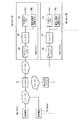
本発明の実施形態として示す充電システムは、例えば図1に示すように構成されている。この充電システムは、電動車両(電気自動車)に対する電力の充電を管理するものである。この充電システムにおいて、電動車両は、充電池、充電池に充電を行う充電装置、充電池に蓄積された電力を動力に変換する動力変換装置等を備える。この電動車両は、当該動力によって駆動機構を動作させて、走行する。 A charging system shown as an embodiment of the present invention is configured as shown in FIG. 1, for example. This charging system manages charging of electric power to an electric vehicle (electric vehicle). In this charging system, the electric vehicle includes a rechargeable battery, a charging device that charges the rechargeable battery, a power conversion device that converts electric power stored in the rechargeable battery into power, and the like. The electric vehicle travels by operating the drive mechanism with the power.
充電システムは、複数の車載装置1a,1b・・・と、サーバ装置としてのセンタサーバ2と、電力会社サーバ3と、宅内システム4a,4b・・・とを含む。以下、車載装置を総称する場合には単に「車載装置1」と呼ぶ。また、宅内システムを総称する場合には単に「宅内システム4」と呼ぶ。例えば、車載装置1a及び宅内システム4aのユーザがAさんであり、車載装置1b及び宅内システム4bのユーザがBさんというように、ユーザが電動車両を利用して住宅に帰ることを想定している。
The charging system includes a plurality of in-vehicle devices 1a, 1b,..., A
この充電システムにおいて、宅内システム4は、住宅ごとに設けられる。宅内システム4は、電力会社が管理する所定の電力管理エリアに属する。この所定の電力管理エリアは、電力会社が電力需要上限を管理する範囲である。宅内システム4は、後述するように、自身が属する電力管理エリアの電力需要に応じて、自身が属する電力管理エリアの上限を超えないように消費電力を調整するよう要求される。 In this charging system, the home system 4 is provided for each house. The in-home system 4 belongs to a predetermined power management area managed by the power company. This predetermined power management area is a range in which the power company manages the power demand upper limit. As will be described later, the in-home system 4 is requested to adjust the power consumption so as not to exceed the upper limit of the power management area to which the home system 4 belongs in accordance with the power demand of the power management area to which the home system 4 belongs.
宅内システム4は、センタサーバ2と通信可能となっている。また、宅内システム4は、センタサーバ2を介して車載装置1との間で通信が可能となっている。宅内システム4は、住宅内における電力の使用状況を監視する動作や、電力の使用状況を制御する動作を行う。
The home system 4 can communicate with the
宅内システム4は、ブロードバンドルータ41、コントローラ42、コントロールパネル43、及び、電気自動車用の充電スタンド44を有する。
The in-home system 4 includes a
ブロードバンドルータ41は、センタサーバ2との間で通信を行う。
The
コントロールパネル43は、例えばタッチパネル等からなる。コントロールパネル43は、ユーザに各種情報を提示する表示インタフェースや、ユーザの操作を受け付ける操作インタフェースを有している。このコントロールパネル43は、ドアホン等にも接続され、各種の表示、操作が可能である。
The
特に、このコントロールパネル43は、車載装置1を介してセンタサーバ2から受信した所謂「帰る通知」を表示させる。この帰る通知は、車載装置1を搭載した電動車両から送信された移動情報及び残量情報を含み、以降の時間において電動車両に乗って帰宅することを表す。また、コントロールパネル43は、センタサーバ2から送信された充電スタンド44の充電スケジュール変更要求を表示させる。
In particular, the
コントローラ42は、コントロールパネル43及び充電スタンド44の動作を制御する。コントローラ42は、コントロールパネル43の表示インタフェースに対して各種情報を表示させる。また、コントローラ42は、コントロールパネル43の操作インタフェースからの操作指示に応じて、宅内における各種電気機器を制御する。
The
特に、コントローラ42は、センタサーバ2からの要求に応じて充電スタンド44の充電スケジュール変更要求をコントロールパネル43に表示させる。その後、コントローラ42は、充電スタンド44の充電スケジュール変更要求を受け付ける操作がされたことに応じて、充電スタンド44の充電スケジュールを変更する。
In particular, the
このようなコントローラ42は、ブロードバンドルータ41等を介してサーバ装置としてのセンタサーバ2との間で通信可能である。充電スタンド44は、電動車両に搭載された充電池に対する充電を制御する充電制御装置として機能する。
Such a
充電スタンド44は、電動車両に備えられた充電池の充電時に、車載装置1が搭載された電動車両が接続される。充電スタンド44は、予め設定された充電スケジュールに従って、又は、ユーザの操作に従って、電動車両に対する充電を開始する。充電スタンド44は、コントローラ42から供給された制御信号や、図示しない操作インタフェースに対するユーザの操作に応じて、電動車両に対する充電を行う。
The charging
特に、充電スタンド44は、コントローラ42から供給された制御信号に応じて、電動車両に対する充電スケジュールが設定される。この充電スケジュールは、例えば、充電開始時刻、全充電量、単位時間当たりの充電量、充電時間、充電終了時刻等が設定される。充電スタンド44は、充電スケジュールが設定された場合、当該充電スケジュールに従って、自動的に電動車両に対する充電を行う。
In particular, the charging
また、充電スタンド44は、コントローラ42から供給された制御信号に従って、充電スケジュールの変更を行う。充電スタンド44は、充電スケジュールを変更する。具体的には、所定の電力管理エリアにおける電力需要のピークを低減するような充電スケジュールの変更要求が供給される。この要求に応じ、充電スタンド44は、当該充電スケジュールの変更要求に応じて、充電開始時刻、全充電量、単位時間当たりの充電量、充電時間、充電終了時刻等を変更する。
In addition, the charging
車載装置1は、図2に示すように、GPS処理部11、ナビゲーション機能部12、通信部13を有する。
As illustrated in FIG. 2, the in-vehicle device 1 includes a
通信部13は、無線通信回路等を有し、無線通信によってインターネットを介してセンタサーバ2と通信を行う。通信部13は、電動車両の移動情報と当該電動車両における充電池の残量情報とを含む帰る通知をセンタサーバ2に送信する。電動車両の移動情報は、移動中や停止中であることを示す移動状態、移動先等を含む。
The
GPS処理部11は、GPS衛星と通信を行って、自己の現在位置を取得する。
The
ナビゲーション機能部12は、GPS処理部11により取得された現在位置、地図データ、及び、設定された目的地等に基づいて、現在位置から目的地までの推奨経路を演算する。ナビゲーション機能部12は、演算された推奨経路及び現在位置に従って、電動車両の進行方向を案内する表示動作及び音声出力動作を行う。
The
ナビゲーション機能部12は、電動車両のユーザの操作を受け付けて、帰る通知を送信する。このとき、ナビゲーション機能部12は、電動車両の移動先としての自宅と、当該電動車両における充電池の残量情報とを含む移動情報を生成する。また、ナビゲーション機能部12は、帰る通知に、電動車両の現在位置、現在位置から自宅までの距離、自宅への到着予想時間を含めてもよい。
The
なお、電動車両からセンタサーバ2に対して移動情報や残量情報を送信する手法としては、ナビゲーション機能部12に限らず、携帯電話やパーソナルコンピュータ等の通信手段を利用してもよいことは勿論である。
It should be noted that the method for transmitting the movement information and the remaining amount information from the electric vehicle to the
電力会社サーバ3は、センタサーバ2との間でインターネットを介した通信が可能となっている。電力会社サーバ3は、宅内システム4に電力を供給する電力会社によって、その動作が制御される。電力会社サーバ3は、エリア電力管理部31と、通信部32とを有する。
The power company server 3 can communicate with the
通信部32は、センタサーバ2との間でインターネットを介して通信を行う。
The
エリア電力管理部31は、所定の電力管理エリアにおける上限電力を取得する。また、エリア電力管理部31は、所定の電力管理エリアの使用可能電力のうち、電動車両に使用可能な上限電力を取得してもよい。電力会社サーバ3は、例えば各電力管理エリアに対して送電を行う送電システム5A,・・・,5Nと接続されている。例えば送電システム5Aは、電力管理エリアAに含まれる複数の住宅の宅内システム4Aに対して電力供給を行っている。電力会社サーバ3は、各送電システム5から電力管理エリアに供給している供給電力を取得する。エリア電力管理部31は、所定の電力管理エリアに含まれる宅内システム4と通信するセンタサーバ2に対して、当該電力管理エリアの上限電力を供給する。エリア電力管理部31は、例えば1時間単位や30分単位といったように、所定時間毎に各電力管理エリアの上限電力をセンタサーバ2に送信する。
The area
センタサーバ2は、需要予測部21、充電スケジュール管理部22、通信部23を有する。センタサーバ2は、記憶部や通信I/F回路、CPU及びプログラムを含むコンピュータであり、CPUがプログラムを実行する。これにより、センタサーバ2のプログラムは、後述するように充電スケジュールの変更要求をする手順を実行させる。
The
通信部23は、車載装置1、電力会社サーバ3及び宅内システム4との間で通信を行う。通信部23は、車載装置1から送信された帰る通知としての移動情報を受信する。これによりセンタサーバ2は、電動車両の移動情報と、電動車両における充電池の残量情報を取得する。通信部23は、電力会社サーバ3から各電力管理エリアの電力上限通知を取得する。
The
需要予測部21は、電動車両の移動情報と当該電動車両における充電池の残量情報とを含む移動情報に基づいて当該移動情報に含まれる移動先を含む所定の電力管理エリアの需要電力を予測する。需要予測部21は、複数の車載装置1から移動情報を電力管理エリアごとに集計し、当該電力管理エリアにおいて電動車両の充電池が充電される時間帯を推定する。需要予測部21は、例えば1時間ごとといった所定の時間間隔ごとに電力管理エリアの需要電力を予測する。
The
充電スケジュール管理部22は、需要予測部21により予測された電力管理エリアごとの需要電力に基づいて、当該電力管理エリアに含まれる充電スタンド44に充電スケジュール変更要求を送出する。このとき、充電スケジュール管理部22は、各電力管理エリアについて電力会社サーバ3から送信された電力上限通知と需要予測部21により予測された需要電力とを比較する。充電スケジュール管理部22は、電力上限通知と、予測された電力需要との比較結果に基づいて充電スケジュールの変更要求を生成する。例えば、予測された需要電力が上限電力の80%に達した場合、当該時間帯においては電動車両への充電動作を控える充電スケジュールの変更要求を生成する。充電スケジュール管理部22は、充電スケジュールの変更要求を生成した場合、当該充電スケジュールの変更要求を、宅内システム4に送信する。
Based on the demand power for each power management area predicted by the
宅内システム4は、充電スケジュールの変更要求を受信すると、充電スタンド44によって、充電スケジュールの変更要求に応じて、電動車両に備えられた充電池に対する充電動作のスケジュールを変更する。このとき、宅内システム4は、コントローラ42によって充電スケジュール変更要求をコントロールパネル43に表示させる。コントローラ42は、コントロールパネル43に対する変更要求の受入操作を検出した場合に、充電スタンド44に充電スケジュール変更要求を送信する。この要求に応じて、充電スタンド44は、例えば、充電開始時刻、単位時間当たりの充電量、充電時間等を変更する。
When the in-home system 4 receives the request for changing the charging schedule, the charging
なお、本実施形態では、需要予測及び充電スケジュール管理をセンタサーバ2によって行ったが、当該処理を電力会社サーバ3によって行ってもよく、更に他のサーバによって行ってもよい。
In the present embodiment, the demand prediction and the charging schedule management are performed by the
つぎに、上述したように構成された充電システムにおける動作について、図3を参照して説明する。 Next, the operation of the charging system configured as described above will be described with reference to FIG.
この充電システムは、電力会社サーバ3からセンタサーバ2に対して、当該センタサーバ2が通信可能な宅内システム4が属する電力管理エリアの電力上限通知S1が供給される。この電力上限通知S1は、所定時間毎にセンタサーバ2に送信される。
In this charging system, a power upper limit notification S1 of a power management area to which a home system 4 with which the
ユーザが自宅に帰るときに車載装置1が操作されると(ステップST1)、車載装置1は、帰る通知S2をセンタサーバ2に送信する。この帰る通知S2には、移動情報、充電池の残量情報等が含まれる。その後、車載装置1は、電動車両が移動するごと又は所定時間ごとに、移動情報S3を送信する。
When the in-vehicle device 1 is operated when the user returns home (step ST1), the in-vehicle device 1 transmits a return notification S2 to the
センタサーバ2は、帰る通知S2を受信すると、当該帰る通知S2を、電動車両に対応した宅内システム4に送信する。このとき、センタサーバ2は、帰る通知S2に含まれたID情報に対応して予め登録しておいた宅内システム4のアドレスに対して帰る通知S2を送信する。
When the
宅内システム4は、帰る通知S2を受信すると、コントロールパネル43に、電動車両の位置、帰宅予想時刻等を表示する。
When the home system 4 receives the return notification S <b> 2, the home system 4 displays the position of the electric vehicle, the expected home time, and the like on the
センタサーバ2は、帰る通知S2及び当該帰る通知S2後に送信された移動情報S3に基づいて、各宅内システム4における充電スタンド44の充電スケジュールを作成する。このとき、センタサーバ2は、電動車両の帰宅時刻に基づく充電開始時刻、残量情報に基づく充電量に従って、各宅内システム4の充電スケジュールを作成する(ステップST2)。センタサーバ2により作成された充電スケジュールS4は、各宅内システム4に送信される。
The
宅内システム4は、充電スケジュールS4を受信すると、当該充電スケジュールをコントロールパネル43に表示させ、充電スタンド44に、当該充電スケジュールを設定する。これにより、充電スタンド44は、充電スケジュールで特定された充電開始時刻から充電を開始するよう予約される。充電スケジュールの設定以降、宅内システム4は、充電スタンド44の充電実績を取得し、所定時間毎に充電実績通知S5をセンタサーバ2に送信する。
Upon receiving the charging schedule S4, the home system 4 displays the charging schedule on the
センタサーバ2は、電力会社サーバ3から電力上限通知S1、車載装置1からの帰る通知S2及び移動情報S3、及び、宅内システム4から充電実績通知S5を受信している。センタサーバ2は、需要予測部21によって、帰る通知S2及び移動情報S3に基づいて各電力管理エリアの需要予測を行っている。センタサーバ2は、需要予測によって得られた各電力管理エリアの電力需要が、当該電力管理エリアの電力上限からみて充電スケジュールの変更が必要かを判断する(ステップST4)。
The
このとき、センタサーバ2は、充電スケジュール管理部22によって、電力管理エリアの電力消費量を電力会社サーバ3を介して取得する。センタサーバ2は、取得された電力消費量と需要予測部21により予測された当該電力管理エリアにおける需要電力とを比較して一致度を算出する。例えば、電動車両の帰宅時刻が渋滞やユーザの都合によって変動する場合がある。この場合、帰る通知S2に含まれる残量情報及び移動情報に基づいて宅内システム4において充電されるという電力需要の予測がずれる。
At this time, the
このため、需要予測部21は、充電スケジュール管理部22により評価された一致度が所定値よりも低い場合に、帰る通知S2及び移動情報S3に基づく電力管理エリアにおける需要電力の予測を再度行う。そして、充電スケジュール管理部22は、需要予測部21より再度行われた予測結果としての需要電力に基づいて、当該電力管理エリアに含まれる充電スタンド44に充電スケジュール変更要求を送出する。この充電スケジュール変更要求は、充電スケジュール通知S6として宅内システム4に送信される。
For this reason, when the degree of coincidence evaluated by the charging
また、宅内システム4は、充電スケジュール管理部22によって、一致度に基づいて、電力管理エリアにおける充電スケジュール変更要求の生成処理を学習することが望ましい。例えば、帰宅時間が遅くなるユーザの場合には、充電スケジュールを遅くシフトさせる。また、電力管理エリアによっては交通量が多く渋滞が発生しやすい場合、当該電力管理エリアでは、充電開始時刻が遅くなる。したがって、充電スケジュール管理部22は、電力管理エリアによって充電パターンを学習し、帰宅時間を調整できる。更に、センタサーバ2は、電力管理エリアにおける電力需要予測のために、遠出をする電動車両を登録しておくことが望ましい。この充電スケジュール生成処理の学習により、精度を高めた充電スケジュールを立案することができる。
In addition, the home system 4 desirably learns the charging schedule change request generation processing in the power management area based on the degree of coincidence by the charging
これにより、充電スケジュール管理部22は、各電力管理エリアの電力需要のピークを抑制又はシフト(移動)するよう、各宅内システム4の充電開始時刻、単位時間当たりの充電量、充電時間等を変更する。
Thereby, the charging
宅内システム4は、充電スケジュール通知S6を受信すると、コントロールパネル43に対して表示又は放音等をすることによって、アラーム通知する。また、宅内システム4は、ステップST3にて設定した充電スケジュールを変更する(ステップST6)。
Upon receipt of the charging schedule notification S6, the in-home system 4 notifies the alarm by displaying or emitting sound to the
その後、宅内システム4は、充電開始時刻となったと判定した場合(ステップST7)、充電スタンド44に対して制御信号S7を供給する。この制御信号S7に応じて、充電スタンド44は、充電を開始する(ステップST8)。充電スタンド44が充電を開始したことに応じ、宅内システム4は、センタサーバ2に対して充電実績通知S8を供給する。
Thereafter, when it is determined that the charging start time has come (step ST7), the home system 4 supplies a control signal S7 to the charging
センタサーバ2は、宅内システム4から充電実績通知S8を受信すると、当該充電実績を記憶する(ステップST9)。
When the
以上のように、この充電システムによれば、車載装置1から送信される帰る通知に充電池の残量を含める。これにより、センタサーバ2は、電動車両が宅内システム4にて充電を行うことによる電力需要を予測し、電力管理エリアごとに電動車両の充電に要する電力需要を予測できる。これにより、この充電システムによれば、当該電力管理エリアの電力上限に対して電力管理エリアの電力需要を抑制する充電スケジュールの変更要求を宅内システム4に送信できる。例えば、宅内システム4のユーザに、電動車両に対する充電を行う時間帯をずらす等の通知ができる。これにより、この充電システムは、電動車両の帰宅時間帯に一斉に電動車両が充電されることを回避できる。
As described above, according to this charging system, the remaining charge of the rechargeable battery is included in the return notification transmitted from the in-vehicle device 1. Thereby, the
また、この充電システムによれば、実際の電力管理エリアにおける電力消費量が、需要予測部21により予測された需要電力と一致していない場合には、当該電力管理エリアの電力需要を再予測できる。そして、需要予測部21より再度行われた予測結果としての需要電力に基づいて、当該電力管理エリアに含まれる充電スタンド44に充電スケジュール変更要求を送出することができる。したがって、この充電システムによれば、需要予測部21による需要予測が妥当ではなく充電スケジュールの変更が必要な場合には、宅内システム4に対して充電スケジュールを更新するよう調整できる。
Further, according to this charging system, when the power consumption in the actual power management area does not match the demand power predicted by the
更に、この充電システムによれば、実際の電力管理エリアにおける電力消費量が、需要予測部21により予測された需要電力と一致度に基づいて、電力管理エリアにおける充電スケジュール変更要求の生成処理を学習する。これにより、この充電システムによれば、充電スケジュールの精度を高めることができる。
Furthermore, according to this charging system, learning processing for generating a charging schedule change request in the power management area is learned based on the degree of coincidence of the power consumption in the actual power management area with the demand power predicted by the
なお、上述の実施の形態は本発明の一例である。このため、本発明は、上述の実施形態に限定されることはなく、この実施の形態以外であっても、本発明に係る技術的思想を逸脱しない範囲であれば、設計等に応じて種々の変更が可能であることは勿論である。 The above-described embodiment is an example of the present invention. For this reason, the present invention is not limited to the above-described embodiment, and various modifications can be made depending on the design and the like as long as the technical idea according to the present invention is not deviated from this embodiment. Of course, it is possible to change.
例えば、上述した充電システムは、センタサーバ2から宅内システム4に充電スケジュールの変更要求を送信することによって、ユーザが帰宅したにもかかわらず、電動車両の充電池への充電動作を妨げるものである。したがって、この充電システムは、宅内システム4からセンタサーバ2に充電実績通知を送信したことによって、当該充電実績通知に基づいて、宅内システム4に対して特典を提供するビジネス形態を支援することができる。この宅内システム4に対する特典とは、例えば、電気料金の割引等の情報が挙げられる。センタサーバ2は、宅内システム4の充電実績通知によって、宅内システム4よる充電動作が、充電スケジュールの変更要求によって変更されたことを判定する。この場合、センタサーバ2は、その旨の情報と宅内システム4のIDを電力会社サーバ3に供給する。これにより、電力会社サーバ3は、宅内システム4のIDに係る電気料金を割り引いて、宅内システム4のIDに対応した住宅に対する電気料金を請求できる。
For example, the above-described charging system prevents the charging operation of the rechargeable battery of the electric vehicle even though the user returns home by transmitting a request to change the charging schedule from the
1 車載装置
2 センタサーバ(サーバ装置)
12 ナビゲーション機能部
21 需要予測部
22 充電スケジュール管理部(スケジュール管理部)
31 エリア電力管理部
42 コントローラ(充電制御装置)
1 In-
12
31 Area
Claims (9)
前記サーバ装置との間で通信可能であって前記充電池に対する充電を制御する充電制御装置とを有する充電システムであって、
前記サーバ装置は、前記電動車両の移動先を含む移動情報と当該電動車両における充電池の残量情報とを前記電動車両から受信する通信部と、前記通信部により受信された前記移動先を含む移動情報及び残量情報に基づいて所定エリアごとに前記移動先を含む前記移動情報および前記残量情報を集計し、前記所定エリアにおいて前記電動車両の充電池が充電される時間帯を推定することによって前記所定エリアの需要電力を予測する需要予測部と、前記需要予測部により予測された所定エリアの需要電力に基づいて、前記所定エリアごとの電力上限からみて充電スケジュールの変更が必要な前記所定エリアに含まれる充電制御装置にある時間帯における前記電動車両への充電動作を控えることを要求する充電スケジュール変更要求を送出するスケジュール管理部とを有し、
前記充電制御装置は、前記サーバ装置から送出された充電スケジュール変更要求に応じて、前記電動車両に備えられた充電池に対する充電動作のスケジュールを変更すること
を特徴とする充電システム。 A server device capable of communicating with an electric vehicle driven by electric power stored in a rechargeable battery;
A charging system having a charge control device capable of communicating with the server device and controlling charging of the rechargeable battery,
The server device includes a communication unit that receives movement information including a destination of the electric vehicle and remaining battery charge information in the electric vehicle from the electric vehicle, and the destination received by the communication unit. Aggregating the movement information and the remaining amount information including the destination for each predetermined area based on the movement information and the remaining amount information, and estimating a time zone in which the rechargeable battery of the electric vehicle is charged in the predetermined area. The demand prediction unit that predicts the demand power of the predetermined area by using the demand prediction unit, and the predetermined schedule that needs to be changed in charge schedule in view of the power upper limit for each predetermined area based on the demand power of the predetermined area predicted by the demand prediction unit sending the charging schedule change request that requests to refrain from charging to the electric vehicle in the time zone in the charge control device included in the area And a schedule management unit,
The charging system, wherein the charging control device changes a charging operation schedule for a rechargeable battery provided in the electric vehicle in response to a charging schedule change request sent from the server device.
前記電動車両の移動先を含む移動情報と当該電動車両における充電池の残量情報とを前記電動車両から受信する通信部と、
前記通信部により受信された前記移動先を含む移動情報及び残量情報に基づいて所定エリアごとに前記移動先を含む前記移動情報および前記残量情報を集計し、前記所定エリアごとに前記電動車両の充電池が充電される時間帯を推定することによって前記所定エリアごとの需要電力を予測する需要予測部と、
前記需要予測部により予測された所定エリアの需要電力に基づいて、前記所定エリアごとの電力上限からみて充電スケジュールの変更が必要な前記所定エリアに含まれる充電制御装置にある時間帯における前記電動車両への充電動作を控えることを要求する充電スケジュール変更要求を送出するスケジュール管理部と
を有することを特徴とするサーバ装置。 A server device capable of communicating with an electric vehicle driven by electric power stored in a rechargeable battery, and a charge control device for controlling charging of the rechargeable battery mounted on the electric vehicle,
A communication unit that receives from the electric vehicle movement information including a destination of the electric vehicle and remaining battery charge information in the electric vehicle;
Based on the movement information and remaining amount information including the movement destination received by the communication unit, the movement information and the remaining amount information including the movement destination are totaled for each predetermined area, and the electric vehicle for each predetermined area. A demand prediction unit that predicts demand power for each predetermined area by estimating a time zone in which the rechargeable battery is charged ;
The electric vehicle in a time zone in a charge control device included in the predetermined area that needs to be changed in charge schedule based on the power upper limit for each predetermined area based on the power demand in the predetermined area predicted by the demand prediction unit And a schedule management unit for sending out a charge schedule change request for requesting to refrain from charging operation .
前記サーバ装置のコンピュータを、
前記電動車両の移動先を含む移動情報と当該電動車両における充電池の残量情報とを前記電動車両から受信する通信部、
前記通信部により受信された前記移動先を含む移動情報及び残量情報に基づいて所定エリアごとに前記移動先を含む前記移動情報および前記残量情報を集計し、前記所定エリアごとに前記電動車両の充電池が充電される時間帯を推定することによって前記所定エリアごとの需要電力を予測する需要予測部、および
前記需要予測部により予測された所定エリアの需要電力に基づいて、前記所定エリアごとの電力上限からみて充電スケジュールの変更が必要な前記所定エリアに含まれる充電制御装置にある時間帯における前記電動車両への充電動作を控えることを要求する充電スケジュール変更要求を送出するスケジュール管理部
として機能させることを特徴とするサーバ装置のプログラム。 A program for a server device that can communicate with an electric vehicle driven by electric power stored in a rechargeable battery, and a charge control device that controls charging for the rechargeable battery mounted on the electric vehicle,
A computer of the server device;
A communication unit that receives movement information including a destination of the electric vehicle and remaining battery charge information in the electric vehicle from the electric vehicle;
Based on the movement information and remaining amount information including the movement destination received by the communication unit, the movement information and the remaining amount information including the movement destination are totaled for each predetermined area, and the electric vehicle for each predetermined area. based demand prediction unit predicts the power demand for each of the predetermined area by the rechargeable battery to estimate the time zone to be charged, and the power demand of a predetermined area predicted by the demand prediction unit, each of the predetermined areas As a schedule management unit for sending out a charge schedule change request for requesting to refrain from charging operation to the electric vehicle in a certain time zone in a charge control device included in the predetermined area that needs to be changed in view of the power upper limit of A program of a server device characterized by causing it to function.
前記サーバ装置との間で通信可能であって前記充電池に対する充電を制御する充電制御装置とを有する充電システムであって、
前記サーバ装置は、前記電動車両の移動情報と当該電動車両における充電池の残量情報とを前記電動車両から受信する通信部と、前記通信部により受信された移動情報及び残量情報に基づいて所定エリアの需要電力を予測する需要予測部と、前記需要予測部により予測された所定エリアの需要電力に基づいて、当該所定エリアに含まれる充電制御装置に充電スケジュール変更要求を送出するスケジュール管理部とを有し、
前記充電制御装置は、前記サーバ装置から送出された充電スケジュール変更要求に応じて、前記電動車両に備えられた充電池に対する充電動作のスケジュールを変更し、
前記スケジュール管理部は、前記所定エリアの電力消費量を取得し、取得された電力消費量と前記需要予測部により予測された当該所定エリアにおける需要電力とを比較して一致度を算出し、
前記需要予測部は、前記スケジュール管理部により算出された一致度が所定値よりも低い場合に、前記移動情報及び残量情報に基づく所定エリアにおける需要電力の予測を再度行い、
前記スケジュール管理部は、前記需要予測部より再度行われた予測結果としての需要電力に基づいて、当該所定エリアに含まれる充電制御装置に充電スケジュール変更要求を送出すること
を特徴とする充電システム。 A server device capable of communicating with an electric vehicle driven by electric power stored in a rechargeable battery;
A charging system having a charge control device capable of communicating with the server device and controlling charging of the rechargeable battery,
The server device is based on the communication unit that receives the movement information of the electric vehicle and the remaining amount information of the rechargeable battery in the electric vehicle from the electric vehicle, and the movement information and the remaining amount information received by the communication unit. A demand prediction unit that predicts demand power in a predetermined area, and a schedule management unit that sends out a charge schedule change request to a charge control device included in the predetermined area based on the demand power in the predetermined area predicted by the demand prediction unit And
The charging control device changes a charging operation schedule for a rechargeable battery provided in the electric vehicle in response to a charging schedule change request sent from the server device,
The schedule management unit acquires the power consumption of the predetermined area, compares the acquired power consumption with the demand power in the predetermined area predicted by the demand prediction unit, and calculates the degree of coincidence,
The demand prediction unit, when the degree of coincidence calculated by the schedule management unit is lower than a predetermined value, again predicts demand power in a predetermined area based on the movement information and remaining amount information,
The schedule management unit, based on the power demand as a prediction result performed again from the demand prediction unit, charging you characterized by delivering charging schedule change request to the charge control device included in the predetermined area system.
前記電動車両の移動情報と当該電動車両における充電池の残量情報とを前記電動車両から受信する通信部と、
前記通信部により受信された移動情報及び残量情報に基づいて所定エリアの需要電力を予測する需要予測部と、
前記需要予測部により予測された所定エリアの需要電力に基づいて、当該所定エリアに含まれる充電制御装置に充電スケジュール変更要求を送出するスケジュール管理部と
を有し、
前記スケジュール管理部は、前記所定エリアの電力消費量を取得し、取得された電力消費量と前記需要予測部により予測された当該所定エリアにおける需要電力とを比較して一致度を算出し、
前記需要予測部は、前記スケジュール管理部により算出された一致度が所定値よりも低い場合に、前記移動情報及び残量情報に基づく所定エリアにおける需要電力の予測を再度行い、 前記スケジュール管理部は、前記需要予測部より再度行われた予測結果としての需要電力に基づいて、当該所定エリアに含まれる充電制御装置に充電スケジュール変更要求を送出することを特徴とするサーバ装置。 A server device capable of communicating with an electric vehicle driven by electric power stored in a rechargeable battery, and a charge control device for controlling charging of the rechargeable battery mounted on the electric vehicle,
A communication unit that receives from the electric vehicle movement information of the electric vehicle and remaining information of a rechargeable battery in the electric vehicle;
A demand prediction unit that predicts demand power in a predetermined area based on movement information and remaining amount information received by the communication unit;
Based on the power demand of a predetermined area predicted by the demand prediction unit, possess a schedule management unit for sending a charging schedule change request to the charge control device included in the predetermined area,
The schedule management unit acquires the power consumption of the predetermined area, compares the acquired power consumption with the demand power in the predetermined area predicted by the demand prediction unit, and calculates the degree of coincidence,
When the degree of coincidence calculated by the schedule management unit is lower than a predetermined value, the demand prediction unit performs prediction of demand power again in a predetermined area based on the movement information and remaining amount information, and the schedule management unit A server device that transmits a charge schedule change request to a charge control device included in the predetermined area based on demand power as a prediction result performed again by the demand prediction unit .
前記サーバ装置のコンピュータを、
前記電動車両の移動情報と当該電動車両における充電池の残量情報とを前記電動車両から受信する通信部、
前記通信部により受信された移動情報及び残量情報に基づいて当該移動情報に含まれる移動先を含む所定エリアの需要電力を予測する需要予測部、および
前記需要予測部により予測された所定エリアの需要電力に基づいて、当該所定エリアに含まれる充電制御装置に充電スケジュール変更要求を送出するスケジュール管理部
として機能させ、
前記スケジュール管理部は、前記所定エリアの電力消費量を取得し、取得された電力消費量と前記需要予測部により予測された当該所定エリアにおける需要電力とを比較して一致度を算出し、
前記需要予測部は、前記スケジュール管理部により算出された一致度が所定値よりも低い場合に、前記移動情報及び残量情報に基づく所定エリアにおける需要電力の予測を再度行い、
前記スケジュール管理部は、前記需要予測部より再度行われた予測結果としての需要電力に基づいて、当該所定エリアに含まれる充電制御装置に充電スケジュール変更要求を送出することを特徴とするサーバ装置のプログラム。 A program for a server device that can communicate with an electric vehicle driven by electric power stored in a rechargeable battery, and a charge control device that controls charging for the rechargeable battery mounted on the electric vehicle,
A computer of the server device;
A communication unit that receives from the electric vehicle movement information of the electric vehicle and remaining information of a rechargeable battery in the electric vehicle;
Forecast unit predicts the power demand of a predetermined area including the destination included in the movement information on the basis of the movement information and the balance information received by the communication unit, and a predetermined area predicted by the demand prediction unit Based on the demand power, function as a schedule management unit that sends a charge schedule change request to the charge control device included in the predetermined area ,
The schedule management unit acquires the power consumption of the predetermined area, compares the acquired power consumption with the demand power in the predetermined area predicted by the demand prediction unit, and calculates the degree of coincidence,
The demand prediction unit, when the degree of coincidence calculated by the schedule management unit is lower than a predetermined value, again predicts demand power in a predetermined area based on the movement information and remaining amount information,
The schedule management unit sends a charge schedule change request to a charge control device included in the predetermined area based on demand power as a prediction result performed again by the demand prediction unit . program.
Priority Applications (5)
| Application Number | Priority Date | Filing Date | Title |
|---|---|---|---|
| JP2011204900A JP5873986B2 (en) | 2011-09-20 | 2011-09-20 | Charging system, server device, and server device program |
| PCT/JP2012/005975 WO2013042363A1 (en) | 2011-09-20 | 2012-09-20 | Charging system, server device, and server device program |
| CN201280045532.6A CN103814392B (en) | 2011-09-20 | 2012-09-20 | The program of charging system, server unit and server unit |
| EP12833912.4A EP2759977A4 (en) | 2011-09-20 | 2012-09-20 | Charging system, server device, and server device program |
| US14/203,618 US9387772B2 (en) | 2011-09-20 | 2014-03-11 | Charging system, server device, and program for server device |
Applications Claiming Priority (1)
| Application Number | Priority Date | Filing Date | Title |
|---|---|---|---|
| JP2011204900A JP5873986B2 (en) | 2011-09-20 | 2011-09-20 | Charging system, server device, and server device program |
Publications (2)
| Publication Number | Publication Date |
|---|---|
| JP2013065265A JP2013065265A (en) | 2013-04-11 |
| JP5873986B2 true JP5873986B2 (en) | 2016-03-01 |
Family
ID=47914151
Family Applications (1)
| Application Number | Title | Priority Date | Filing Date |
|---|---|---|---|
| JP2011204900A Active JP5873986B2 (en) | 2011-09-20 | 2011-09-20 | Charging system, server device, and server device program |
Country Status (5)
| Country | Link |
|---|---|
| US (1) | US9387772B2 (en) |
| EP (1) | EP2759977A4 (en) |
| JP (1) | JP5873986B2 (en) |
| CN (1) | CN103814392B (en) |
| WO (1) | WO2013042363A1 (en) |
Families Citing this family (35)
| Publication number | Priority date | Publication date | Assignee | Title |
|---|---|---|---|---|
| JP6081817B2 (en) | 2013-02-26 | 2017-02-15 | 三菱重工業株式会社 | OBE and EV management system |
| JP6038290B2 (en) * | 2013-04-01 | 2016-12-07 | 三菱電機株式会社 | Device, charge control device, and information input / output device |
| JP5623584B1 (en) * | 2013-04-19 | 2014-11-12 | 三菱電機株式会社 | Electric vehicle management system |
| JP6180826B2 (en) * | 2013-07-02 | 2017-08-16 | 株式会社東芝 | Energy management server, energy management method and program |
| JP2015022441A (en) * | 2013-07-17 | 2015-02-02 | 株式会社東芝 | Terminal device, vehicle management information generation method, and vehicle management information generation program |
| CN105556245B (en) | 2013-07-25 | 2020-03-06 | 日产自动车株式会社 | Predictive energy margin guidance system |
| US20160164313A1 (en) * | 2013-07-31 | 2016-06-09 | Nec Corporation | Power supply and demand adjustment system and power supply and demand adjustment method |
| EP2910404A1 (en) * | 2014-02-25 | 2015-08-26 | ABB Technology AG | Self-managing charging poles |
| US20150294329A1 (en) * | 2014-04-11 | 2015-10-15 | Nissan North America, Inc. | System and method of predicting usage of a charging station |
| KR101587581B1 (en) * | 2014-05-12 | 2016-01-26 | 한국전기연구원 | Method of AC charging for electric cars based on demand-responsive and apparatus |
| US9789779B2 (en) | 2014-08-25 | 2017-10-17 | Toyota Jidosha Kabushiki Kaisha | Regional charging control service |
| US10220719B2 (en) * | 2014-11-17 | 2019-03-05 | Siemens Industry, Inc. | EVSE-based energy automation, management, and protection systems and methods |
| US10535999B2 (en) * | 2015-02-25 | 2020-01-14 | Kyocera Corporation | Power control system, power control apparatus, and power control method |
| JP6639646B2 (en) * | 2016-03-29 | 2020-02-05 | 京セラ株式会社 | Power management apparatus, power management system, and power management method |
| KR101916511B1 (en) * | 2016-05-16 | 2018-11-07 | 현대자동차주식회사 | Vehicle system and battery charging method thereof |
| WO2018037261A1 (en) * | 2016-08-23 | 2018-03-01 | Pismo Labs Technology Ltd. | Methods and systems for distributing electricity to multiple loads based on a scheduler and ammeter measurements |
| US9955428B1 (en) | 2016-10-24 | 2018-04-24 | International Business Machines Corporation | Optimizing scheduled charging of battery enabled devices based on a predicted battery consumption factor for an area |
| US9955314B1 (en) * | 2016-10-24 | 2018-04-24 | International Business Machines Corporation | Specifying a map of available locations for recharging battery enabled devices based on a schedule of predicted locations for a user |
| US9955313B1 (en) | 2016-10-24 | 2018-04-24 | International Business Machines Corporation | Scheduling optimized charging of battery enabled devices based on power usage impact data received from multiple sources |
| US9867017B1 (en) | 2016-10-24 | 2018-01-09 | International Business Machines Corporation | Scheduling optimized charging of battery enabled devices based on battery usage impact factors and predicted usage received from multiple sources |
| US10195956B2 (en) * | 2017-06-02 | 2019-02-05 | United Arab Emirates University | Secure charging method for electric vehicles |
| JP6832254B2 (en) * | 2017-07-31 | 2021-02-24 | Kddi株式会社 | Charge control server, charge control system and program |
| US10882411B2 (en) * | 2018-01-18 | 2021-01-05 | Ford Global Technologies, Llc | Smart charging schedules for battery systems and associated methods for electrified vehicles |
| JP7040614B2 (en) * | 2018-06-18 | 2022-03-23 | 日産自動車株式会社 | Vehicle management system, vehicle management computer, and vehicle management method |
| CN108808781A (en) * | 2018-06-22 | 2018-11-13 | 蔚来汽车有限公司 | Electric vehicle reservation charging method and apparatus based on big data |
| CN108973739A (en) * | 2018-08-01 | 2018-12-11 | 芜湖雪影实业有限公司 | A kind of charge control station |
| US20200148073A1 (en) * | 2018-11-13 | 2020-05-14 | Ioan Sasu | Battery quick-change process and system for electric vehicles |
| CN109552107A (en) * | 2018-12-03 | 2019-04-02 | 北京兴达智联科技有限公司 | A kind of electric motor intelligent changes electric system and changes method for electrically |
| US10937113B2 (en) * | 2018-12-06 | 2021-03-02 | GM Global Technology Operations LLC | Energy resource pre-allocation and delivery based on demand |
| JP6892881B2 (en) * | 2019-01-17 | 2021-06-23 | 本田技研工業株式会社 | Controls and programs |
| JP6888034B2 (en) * | 2019-01-24 | 2021-06-16 | 本田技研工業株式会社 | Charge management system and program |
| US11001161B2 (en) | 2019-02-15 | 2021-05-11 | Ford Global Technologies, Llc | Electric vehicle charging scheduler |
| JP7413974B2 (en) * | 2020-10-22 | 2024-01-16 | トヨタ自動車株式会社 | Charging management device, charging management method, and mobile object |
| JP7283459B2 (en) * | 2020-11-12 | 2023-05-30 | トヨタ自動車株式会社 | Charging control system, charging control device and charging control program |
| WO2023188357A1 (en) * | 2022-03-31 | 2023-10-05 | 日本電信電話株式会社 | Charge reservation control device, charge reservation control method, and program |
Family Cites Families (9)
| Publication number | Priority date | Publication date | Assignee | Title |
|---|---|---|---|---|
| US20010051876A1 (en) * | 2000-04-03 | 2001-12-13 | Seigel Ronald E. | System and method for personalizing, customizing and distributing geographically distinctive products and travel information over the internet |
| AU2003258018A1 (en) * | 2002-08-02 | 2004-02-23 | Limoq, Inc. | Method, system and apparatus for providing transportation services |
| JP4786296B2 (en) * | 2005-10-27 | 2011-10-05 | 中国電力株式会社 | Electricity load leveling system |
| US7679336B2 (en) | 2007-02-27 | 2010-03-16 | Ford Global Technologies, Llc | Interactive battery charger for electric vehicle |
| US7693609B2 (en) * | 2007-09-05 | 2010-04-06 | Consolidated Edison Company Of New York, Inc. | Hybrid vehicle recharging system and method of operation |
| JP2009171823A (en) * | 2007-12-21 | 2009-07-30 | Nippon Telegr & Teleph Corp <Ntt> | Power supply control system and method of controlling the same |
| JP4713623B2 (en) * | 2008-09-25 | 2011-06-29 | 株式会社日立製作所 | Charge / discharge management device |
| JP5563574B2 (en) * | 2009-07-15 | 2014-07-30 | パナソニック株式会社 | Power control system, power control method, power control apparatus, and power control program |
| US20110016063A1 (en) * | 2009-07-17 | 2011-01-20 | Gridpoint, Inc. | System and methods for smart charging techniques |
-
2011
- 2011-09-20 JP JP2011204900A patent/JP5873986B2/en active Active
-
2012
- 2012-09-20 WO PCT/JP2012/005975 patent/WO2013042363A1/en active Application Filing
- 2012-09-20 EP EP12833912.4A patent/EP2759977A4/en not_active Withdrawn
- 2012-09-20 CN CN201280045532.6A patent/CN103814392B/en active Active
-
2014
- 2014-03-11 US US14/203,618 patent/US9387772B2/en active Active
Also Published As
| Publication number | Publication date |
|---|---|
| US9387772B2 (en) | 2016-07-12 |
| US20140191722A1 (en) | 2014-07-10 |
| CN103814392A (en) | 2014-05-21 |
| EP2759977A1 (en) | 2014-07-30 |
| JP2013065265A (en) | 2013-04-11 |
| WO2013042363A1 (en) | 2013-03-28 |
| CN103814392B (en) | 2017-12-19 |
| EP2759977A4 (en) | 2015-01-28 |
Similar Documents
| Publication | Publication Date | Title |
|---|---|---|
| JP5873986B2 (en) | Charging system, server device, and server device program | |
| US9744873B2 (en) | Method and control device for charging a battery of a vehicle | |
| CN102916462B (en) | Batter-charghing system and method | |
| US10828996B2 (en) | On-board unit and electric vehicle management system | |
| US10006778B2 (en) | Method and apparatus for vehicular travel assistance | |
| JP5493510B2 (en) | Information providing system, information center, in-vehicle device, and information providing method | |
| JP6595720B2 (en) | Route search device, battery information management device, and program | |
| JP4737307B2 (en) | Plug-in car charging status notification system | |
| JP5494270B2 (en) | Information providing apparatus and information providing method | |
| WO2012046269A1 (en) | Charging control apparatus | |
| JP2018027013A (en) | Control method, program, information processing device and reservation system | |
| JP5050135B2 (en) | SEARCH DEVICE, NAVIGATION DEVICE, INFORMATION PROVIDING DEVICE, SEARCH METHOD, SEARCH PROGRAM, AND RECORDING MEDIUM | |
| KR20120089399A (en) | Method, Server and Terminal of Electric Vehicle for Managing Electric Vehicle Charging System | |
| JP2019095196A (en) | System, method, and program for guiding charging facility | |
| WO2016020997A1 (en) | Information-providing system, information apparatus, and information-providing method | |
| JP6282548B2 (en) | In-vehicle device, linkage system, and charging start time notification method | |
| JP2015194370A (en) | Battery charging rate estimation device and battery charging rate estimation method | |
| JP5903952B2 (en) | Driving condition presentation system | |
| KR20220123906A (en) | Server and method for providing charging station information, and application for providing charging station information | |
| JP2021189640A (en) | Information processing device, information processing method, and program | |
| JP2020134448A (en) | Charging facility guide system and charging facility guide program | |
| JP2014228374A (en) | Information providing apparatus, information providing system, and information providing method | |
| KR20230080138A (en) | Method for providing recommended charging route, charging station information providing server peforming the same, and charging station information providing application for providing recommended charging route | |
| JP2013038909A (en) | Device and method for operating vehicle to be driven by using electric machine | |
| JP2020065396A (en) | Transmission method for driving data and battery data in home energy management system capable of charging electric vehicle |
Legal Events
| Date | Code | Title | Description |
|---|---|---|---|
| A621 | Written request for application examination |
Free format text: JAPANESE INTERMEDIATE CODE: A621 Effective date: 20140711 |
|
| A711 | Notification of change in applicant |
Free format text: JAPANESE INTERMEDIATE CODE: A711 Effective date: 20141009 |
|
| RD03 | Notification of appointment of power of attorney |
Free format text: JAPANESE INTERMEDIATE CODE: A7423 Effective date: 20141016 |
|
| A131 | Notification of reasons for refusal |
Free format text: JAPANESE INTERMEDIATE CODE: A131 Effective date: 20150609 |
|
| A521 | Request for written amendment filed |
Free format text: JAPANESE INTERMEDIATE CODE: A523 Effective date: 20150707 |
|
| TRDD | Decision of grant or rejection written | ||
| A01 | Written decision to grant a patent or to grant a registration (utility model) |
Free format text: JAPANESE INTERMEDIATE CODE: A01 Effective date: 20150728 |
|
| A61 | First payment of annual fees (during grant procedure) |
Free format text: JAPANESE INTERMEDIATE CODE: A61 Effective date: 20150820 |
|
| R151 | Written notification of patent or utility model registration |
Ref document number: 5873986 Country of ref document: JP Free format text: JAPANESE INTERMEDIATE CODE: R151 |