JP2015015800A - Control device, and power management system - Google Patents
Control device, and power management system Download PDFInfo
- Publication number
- JP2015015800A JP2015015800A JP2013140224A JP2013140224A JP2015015800A JP 2015015800 A JP2015015800 A JP 2015015800A JP 2013140224 A JP2013140224 A JP 2013140224A JP 2013140224 A JP2013140224 A JP 2013140224A JP 2015015800 A JP2015015800 A JP 2015015800A
- Authority
- JP
- Japan
- Prior art keywords
- power
- period
- power system
- countermeasure
- control device
- Prior art date
- Legal status (The legal status is an assumption and is not a legal conclusion. Google has not performed a legal analysis and makes no representation as to the accuracy of the status listed.)
- Pending
Links
Images

Classifications
-
- H—ELECTRICITY
- H02—GENERATION; CONVERSION OR DISTRIBUTION OF ELECTRIC POWER
- H02J—CIRCUIT ARRANGEMENTS OR SYSTEMS FOR SUPPLYING OR DISTRIBUTING ELECTRIC POWER; SYSTEMS FOR STORING ELECTRIC ENERGY
- H02J3/00—Circuit arrangements for ac mains or ac distribution networks
- H02J3/28—Arrangements for balancing of the load in a network by storage of energy
- H02J3/32—Arrangements for balancing of the load in a network by storage of energy using batteries with converting means
-
- H—ELECTRICITY
- H02—GENERATION; CONVERSION OR DISTRIBUTION OF ELECTRIC POWER
- H02J—CIRCUIT ARRANGEMENTS OR SYSTEMS FOR SUPPLYING OR DISTRIBUTING ELECTRIC POWER; SYSTEMS FOR STORING ELECTRIC ENERGY
- H02J3/00—Circuit arrangements for ac mains or ac distribution networks
- H02J3/12—Circuit arrangements for ac mains or ac distribution networks for adjusting voltage in ac networks by changing a characteristic of the network load
- H02J3/14—Circuit arrangements for ac mains or ac distribution networks for adjusting voltage in ac networks by changing a characteristic of the network load by switching loads on to, or off from, network, e.g. progressively balanced loading
- H02J3/144—Demand-response operation of the power transmission or distribution network
-
- H—ELECTRICITY
- H02—GENERATION; CONVERSION OR DISTRIBUTION OF ELECTRIC POWER
- H02J—CIRCUIT ARRANGEMENTS OR SYSTEMS FOR SUPPLYING OR DISTRIBUTING ELECTRIC POWER; SYSTEMS FOR STORING ELECTRIC ENERGY
- H02J7/00—Circuit arrangements for charging or depolarising batteries or for supplying loads from batteries
- H02J7/34—Parallel operation in networks using both storage and other dc sources, e.g. providing buffering
- H02J7/35—Parallel operation in networks using both storage and other dc sources, e.g. providing buffering with light sensitive cells
-
- H—ELECTRICITY
- H02—GENERATION; CONVERSION OR DISTRIBUTION OF ELECTRIC POWER
- H02J—CIRCUIT ARRANGEMENTS OR SYSTEMS FOR SUPPLYING OR DISTRIBUTING ELECTRIC POWER; SYSTEMS FOR STORING ELECTRIC ENERGY
- H02J2310/00—The network for supplying or distributing electric power characterised by its spatial reach or by the load
- H02J2310/40—The network being an on-board power network, i.e. within a vehicle
- H02J2310/48—The network being an on-board power network, i.e. within a vehicle for electric vehicles [EV] or hybrid vehicles [HEV]
-
- H—ELECTRICITY
- H02—GENERATION; CONVERSION OR DISTRIBUTION OF ELECTRIC POWER
- H02J—CIRCUIT ARRANGEMENTS OR SYSTEMS FOR SUPPLYING OR DISTRIBUTING ELECTRIC POWER; SYSTEMS FOR STORING ELECTRIC ENERGY
- H02J2310/00—The network for supplying or distributing electric power characterised by its spatial reach or by the load
- H02J2310/50—The network for supplying or distributing electric power characterised by its spatial reach or by the load for selectively controlling the operation of the loads
- H02J2310/56—The network for supplying or distributing electric power characterised by its spatial reach or by the load for selectively controlling the operation of the loads characterised by the condition upon which the selective controlling is based
- H02J2310/58—The condition being electrical
-
- Y—GENERAL TAGGING OF NEW TECHNOLOGICAL DEVELOPMENTS; GENERAL TAGGING OF CROSS-SECTIONAL TECHNOLOGIES SPANNING OVER SEVERAL SECTIONS OF THE IPC; TECHNICAL SUBJECTS COVERED BY FORMER USPC CROSS-REFERENCE ART COLLECTIONS [XRACs] AND DIGESTS
- Y02—TECHNOLOGIES OR APPLICATIONS FOR MITIGATION OR ADAPTATION AGAINST CLIMATE CHANGE
- Y02B—CLIMATE CHANGE MITIGATION TECHNOLOGIES RELATED TO BUILDINGS, e.g. HOUSING, HOUSE APPLIANCES OR RELATED END-USER APPLICATIONS
- Y02B70/00—Technologies for an efficient end-user side electric power management and consumption
- Y02B70/30—Systems integrating technologies related to power network operation and communication or information technologies for improving the carbon footprint of the management of residential or tertiary loads, i.e. smart grids as climate change mitigation technology in the buildings sector, including also the last stages of power distribution and the control, monitoring or operating management systems at local level
- Y02B70/3225—Demand response systems, e.g. load shedding, peak shaving
-
- Y—GENERAL TAGGING OF NEW TECHNOLOGICAL DEVELOPMENTS; GENERAL TAGGING OF CROSS-SECTIONAL TECHNOLOGIES SPANNING OVER SEVERAL SECTIONS OF THE IPC; TECHNICAL SUBJECTS COVERED BY FORMER USPC CROSS-REFERENCE ART COLLECTIONS [XRACs] AND DIGESTS
- Y02—TECHNOLOGIES OR APPLICATIONS FOR MITIGATION OR ADAPTATION AGAINST CLIMATE CHANGE
- Y02T—CLIMATE CHANGE MITIGATION TECHNOLOGIES RELATED TO TRANSPORTATION
- Y02T90/00—Enabling technologies or technologies with a potential or indirect contribution to GHG emissions mitigation
- Y02T90/10—Technologies relating to charging of electric vehicles
- Y02T90/16—Information or communication technologies improving the operation of electric vehicles
- Y02T90/167—Systems integrating technologies related to power network operation and communication or information technologies for supporting the interoperability of electric or hybrid vehicles, i.e. smartgrids as interface for battery charging of electric vehicles [EV] or hybrid vehicles [HEV]
-
- Y—GENERAL TAGGING OF NEW TECHNOLOGICAL DEVELOPMENTS; GENERAL TAGGING OF CROSS-SECTIONAL TECHNOLOGIES SPANNING OVER SEVERAL SECTIONS OF THE IPC; TECHNICAL SUBJECTS COVERED BY FORMER USPC CROSS-REFERENCE ART COLLECTIONS [XRACs] AND DIGESTS
- Y04—INFORMATION OR COMMUNICATION TECHNOLOGIES HAVING AN IMPACT ON OTHER TECHNOLOGY AREAS
- Y04S—SYSTEMS INTEGRATING TECHNOLOGIES RELATED TO POWER NETWORK OPERATION, COMMUNICATION OR INFORMATION TECHNOLOGIES FOR IMPROVING THE ELECTRICAL POWER GENERATION, TRANSMISSION, DISTRIBUTION, MANAGEMENT OR USAGE, i.e. SMART GRIDS
- Y04S20/00—Management or operation of end-user stationary applications or the last stages of power distribution; Controlling, monitoring or operating thereof
- Y04S20/20—End-user application control systems
- Y04S20/222—Demand response systems, e.g. load shedding, peak shaving
-
- Y—GENERAL TAGGING OF NEW TECHNOLOGICAL DEVELOPMENTS; GENERAL TAGGING OF CROSS-SECTIONAL TECHNOLOGIES SPANNING OVER SEVERAL SECTIONS OF THE IPC; TECHNICAL SUBJECTS COVERED BY FORMER USPC CROSS-REFERENCE ART COLLECTIONS [XRACs] AND DIGESTS
- Y04—INFORMATION OR COMMUNICATION TECHNOLOGIES HAVING AN IMPACT ON OTHER TECHNOLOGY AREAS
- Y04S—SYSTEMS INTEGRATING TECHNOLOGIES RELATED TO POWER NETWORK OPERATION, COMMUNICATION OR INFORMATION TECHNOLOGIES FOR IMPROVING THE ELECTRICAL POWER GENERATION, TRANSMISSION, DISTRIBUTION, MANAGEMENT OR USAGE, i.e. SMART GRIDS
- Y04S30/00—Systems supporting specific end-user applications in the sector of transportation
- Y04S30/10—Systems supporting the interoperability of electric or hybrid vehicles
- Y04S30/12—Remote or cooperative charging
Abstract
Description
本発明は、蓄電池の充電および放電を制御する制御装置、および制御装置を備える電力管理システムに関する。 The present invention relates to a control device that controls charging and discharging of a storage battery, and a power management system including the control device.
近年、太陽光発電設備のように電力系統への電力の逆潮流が可能な電力供給設備の普及が進んでいる。電力供給設備が発電した電力は、需要家に設けられた電気負荷で消費されるほか、電力系統に逆潮流される。 2. Description of the Related Art In recent years, power supply facilities capable of reverse power flow to a power system, such as solar power generation facilities, have been spreading. The electric power generated by the power supply facility is consumed by the electric load provided at the consumer, and is also reversely flowed to the power system.
電力供給設備のなかでも、太陽光、風力、水力、地熱などの自然エネルギーを電力に変換する発電設備は、生成される電力を人為的に調節することが困難である。この種の発電設備は、電力変換装置(パワーコンディショナ)を備えており、電力変換装置による変換効率を低減させることにより出力を抑制することは可能である。 Among power supply facilities, a power generation facility that converts natural energy such as sunlight, wind power, hydropower, and geothermal heat into power is difficult to artificially adjust the generated power. This type of power generation equipment includes a power conversion device (power conditioner), and it is possible to suppress the output by reducing the conversion efficiency of the power conversion device.
ところで、電力供給設備の密度が高まると、電力系統に供給される電力量が電力系統から消費される電力量に対して過剰になり、結果的に、電力系統の電圧が上昇する可能性がある。たとえば、単相3線式200/100Vの低圧配電線路であれば、電気事業法によって、電力系統の電圧(電圧線と中性線の線間電圧)を101±6V(95〜107V)の範囲に制御することが求められる。 By the way, when the density of the power supply facility increases, the amount of power supplied to the power system becomes excessive with respect to the amount of power consumed from the power system, and as a result, the voltage of the power system may increase. . For example, in the case of a single-phase three-wire 200 / 100V low-voltage distribution line, the electric power system voltage (voltage between the voltage line and the neutral line) is within a range of 101 ± 6V (95 to 107V) according to the Electric Utility Law. To be controlled.
電力系統の電圧が上限値である107Vを超える可能性がある場合、電力系統において対策を講じることが考えられるが、この種の対策は、電気事業者のみが大きな投資コストを負担することになるから、現状では採用が困難である。そのため、現状では、需要家において、電力系統への逆潮流を行う電力を低減させる対策が広く採用されている。 If there is a possibility that the voltage of the electric power system exceeds the upper limit of 107 V, it is conceivable to take measures in the electric power system, but this type of countermeasure only bears a large investment cost. Therefore, it is difficult to adopt at present. Therefore, at present, measures for reducing the power for reverse power flow to the power system are widely adopted by consumers.
しかしながら、この技術は、電力供給設備が発電した電力の一部を無駄に捨てていることになるから、需要家にとっては電力供給設備を導入したことによる費用対効果が損なわれることになる。また、電力供給設備を導入することによる費用対効果が低いと、新たに電力供給装置を導入しようとする意欲が損なわれる。 However, since this technology is a waste of a part of the electric power generated by the power supply facility, the cost effectiveness of the customer due to the introduction of the power supply facility is impaired. In addition, if the cost effectiveness of introducing power supply equipment is low, the willingness to introduce a new power supply device is impaired.
一方、大容量の蓄電池を搭載した電動車両の普及に鑑みて、電動車両に搭載された蓄電池を電力系統に電気的に接続し、蓄電池の充電および放電を制御することによって、電力系統の電圧を制限範囲に維持する技術が提案されている(たとえば、特許文献1参照)。特許文献1には、電力系統の電圧が第1の閾値を超えると、電動車両に搭載された蓄電池の充電を行い、電力系統の電圧が第2の閾値を下回ると、電動車両に搭載された蓄電池からの放電を行う技術が記載されている。
On the other hand, in view of the widespread use of electric vehicles equipped with large-capacity storage batteries, the storage battery mounted on the electric vehicle is electrically connected to the electric power system, and charging and discharging of the storage battery are controlled, thereby controlling the voltage of the electric power system. A technique for maintaining the limit range has been proposed (see, for example, Patent Document 1). In
しかしながら、引用文献1に記載された技術は、電力系統の電圧の変化に対して、電動車両の充電および放電をリアルタイムで行っているに過ぎない。したがって、この技術は、電動車両の蓄電池が満充電に達していれば、電力系統の電圧を引き下げるために利用することができないという問題を有している。
However, the technique described in the cited
本発明は、電動車両に搭載された蓄電池を利用しながらも電力系統の電圧を確実に引き下げることができるようにした制御装置を提供することを目的とし、さらに、この制御装置を用いた電力管理システムを提供することを目的とする。 An object of the present invention is to provide a control device that can reliably lower the voltage of the power system while using a storage battery mounted on an electric vehicle, and further, power management using the control device The purpose is to provide a system.
本発明に係る制御装置は、電力系統から受電する複数の需要家のうちの一部または全部の需要家に設けられ、電動車両に搭載された走行用の蓄電池の充電および放電を制御する制御装置であって、前記電力系統の電圧が制限範囲の上限値を超えると予測される期間を対策期間とし、前記対策期間において、前記電力系統の電圧が前記制限範囲を維持するように前記蓄電池の充電を指示する指示部と、前記対策期間において前記電力系統の電圧を前記制限範囲に維持するための充電が可能になるように、前記対策期間より前に前記蓄電池の残容量を調節する調節部とを備えることを特徴とする。 A control device according to the present invention is provided in some or all of a plurality of consumers that receive power from an electric power system, and controls the charging and discharging of a running storage battery mounted on an electric vehicle. A period during which the voltage of the power system is predicted to exceed the upper limit value of the limit range is a countermeasure period, and charging of the storage battery is performed so that the voltage of the power system maintains the limit range in the countermeasure period. An adjustment unit that adjusts the remaining capacity of the storage battery before the countermeasure period so as to enable charging to maintain the voltage of the power system in the limit range in the countermeasure period; It is characterized by providing.
この制御装置において、前記電力系統から受電する前記複数の需要家のうちの一部または全部の需要家に、自然エネルギーにより発電し、かつ発電した電力を前記電力系統に逆潮流することが許容されている発電設備が設置されている場合に、前記発電設備が発電する電力と前記需要家で消費する電力とを予測することにより前記対策期間を定める予測部を備えることが好ましい。 In this control device, a part or all of the plurality of consumers that receive power from the power system is allowed to generate power with natural energy and to reversely flow the generated power to the power system. When a power generation facility is installed, it is preferable to include a prediction unit that determines the countermeasure period by predicting the power generated by the power generation facility and the power consumed by the consumer.
この制御装置において、前記発電設備は、太陽電池を備える太陽光発電設備であることが好ましい。 In this control device, the power generation facility is preferably a solar power generation facility including a solar battery.
この制御装置において、前記対策期間より前に、前記対策期間を前記電動車両の利用を控えさせる第1の期間として提示装置に通知する第1の通知部を備えることが好ましい。 Preferably, the control device includes a first notification unit that notifies the presentation device of the countermeasure period as a first period that refrains from using the electric vehicle before the countermeasure period.
この制御装置において、前記対策期間より前に、前記対策期間を除く期間を前記電動車両の利用を許可する第2の期間として提示装置に通知する第2の通知部を備えることが好ましい。 Preferably, the control device includes a second notification unit that notifies the presentation device of a period excluding the countermeasure period as a second period permitting the use of the electric vehicle before the countermeasure period.
この制御装置において、前記電力系統から受電する前記複数の需要家のうちの一部または全部の需要家に、前記電力系統に接続され、かつ充電および放電を行う蓄電設備が設置されている場合に、前記調節部は、前記対策期間より前に、前記対策期間のうちで前記電動車両を利用する時間が指定されると、前記対策期間において前記電力系統の電圧を前記制限範囲に維持するための充電が可能になるように、前記対策期間より前に前記蓄電設備の残容量を調節することが好ましい。 In this control device, when some or all of the plurality of consumers that receive power from the power system are provided with power storage equipment that is connected to the power system and performs charging and discharging. The adjustment unit is configured to maintain the voltage of the electric power system in the limit range in the countermeasure period when a time for using the electric vehicle is designated in the countermeasure period before the countermeasure period. It is preferable to adjust the remaining capacity of the power storage facility before the countermeasure period so that charging is possible.
本発明に係る電力管理システムは、自然エネルギーにより発電し、かつ発電した電力を前記電力系統に逆潮流することが許容されている発電設備と、前記制御装置とを備えることを特徴とする。 The power management system according to the present invention includes a power generation facility that generates power using natural energy and is allowed to reversely flow the generated power to the power system, and the control device.
本発明の構成によれば、電動車両に搭載された走行用の蓄電池を充電することにより、電力系統の電圧が制限範囲を超えて上昇することを防止できる。つまり、専用の蓄電設備を設けることなく電力系統の電圧が制限範囲を超えて上昇することを防止できる。また、電力系統の電圧が制限範囲の上限値を超える期間を対策期間として予測し、対策期間の前に蓄電池の残容量を調節するから、電動車両に搭載された蓄電池を利用しながらも対策期間には電力系統の電圧を確実に引き下げられるという効果が得られる。 According to the configuration of the present invention, it is possible to prevent the voltage of the power system from rising beyond the limit range by charging the storage battery for traveling mounted on the electric vehicle. That is, it is possible to prevent the voltage of the power system from rising beyond the limit range without providing a dedicated power storage facility. In addition, the period during which the voltage of the power system exceeds the upper limit of the limit range is predicted as a countermeasure period, and the remaining capacity of the storage battery is adjusted before the countermeasure period, so the countermeasure period while using the storage battery mounted on the electric vehicle Has the effect of reliably reducing the voltage of the power system.
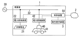
図1、図2に示すように、以下に説明する制御装置50は、電力系統30から受電する複数の需要家1のうちの一部または全部の需要家1に設けられ、電動車両40に搭載された走行用の蓄電池41の充電および放電を制御する。この制御装置50は、指示部521と調節部522とを備える。指示部521は、電力系統30の電圧が制限範囲の上限値を超えると予測される期間を対策期間とし、対策期間において、電力系統の電圧が制限範囲を維持するように蓄電池41の充電を指示する。調節部522は、対策期間において電力系統30の電圧を制限範囲に維持するための充電が可能になるように、対策期間より前に蓄電池41の残容量を調節する。
As shown in FIGS. 1 and 2, the
電力系統30から受電する複数の需要家1のうちの一部または全部の需要家1に、自然エネルギーにより発電し、かつ発電した電力を電力系統30に逆潮流することが許容されている発電設備が設置されていることが望ましい。この場合、発電設備が発電する電力と需要家1で消費する電力とを予測することにより対策期間を定める予測部523を備えることが望ましい。また、発電設備は、太陽電池21を備える太陽光発電設備であることが望ましい。
A power generation facility in which a part or all of the plurality of
制御装置50は、対策期間より前に、対策期間を電動車両40の利用を控えさせる第1の期間として提示装置(操作表示装置3)に通知する第1の通知部524を備えることが望ましい。また、制御装置50は、対策期間より前に、対策期間を除く期間を電動車両40の利用を許可する第2の期間として提示装置(操作表示装置3)に通知する第2の通知部525を備えることが望ましい。
The
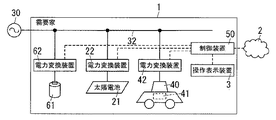
図3に示すように、電力系統30から受電する複数の需要家1のうちの一部または全部の需要家1に、電力系統30に接続され、かつ充電および放電を行う蓄電設備(蓄電池61および電力変換装置62)が設置されている構成を採用してもよい。調節部522は、対策期間より前に、対策期間のうちで電動車両40を利用する時間が指定されると、対策期間において電力系統30の電圧を制限範囲に維持するための充電が可能になるように、対策期間より前に蓄電設備の残容量を調節することが望ましい。
As shown in FIG. 3, a power storage facility (
以下、本実施形態を詳述する。電力供給設備は、発電設備であって、とくに太陽光発電設備を想定する。電力供給設備は、自然エネルギーを利用して発電する構成であれば、風力、水力、地熱などにより発電する構成であってもよい。また、需要家1は、戸建て住宅を想定している。
Hereinafter, this embodiment will be described in detail. The power supply facility is a power generation facility, and particularly a solar power generation facility is assumed. As long as the power supply facility is configured to generate power using natural energy, the power supply facility may be configured to generate power using wind power, hydraulic power, geothermal heat, or the like. Moreover, the
太陽光発電設備は、図2に示すように、太陽電池21と、太陽電池21から出力される直流電力を交流電力に変換する電力変換装置22とを備える。太陽光発電設備は、需要家1の内部配線のための電力線32に接続され(多くの場合に分電盤に接続される)、電力系統30との系統連系が可能になっている。すなわち、需要家1が電力系統30から受電した電力と、太陽光発電設備が発電した電力とは、需要家1に設けられた電気負荷31に供給可能であり、太陽光発電設備が発電した電力は、電力系統30への逆潮流も可能になっている。
As shown in FIG. 2, the solar power generation facility includes a
さらに、電力線32には、蓄電池41の電気エネルギーを用いて走行する電動車両40との間で電力の授受が可能な電力変換装置42が接続される。電動車両40は、ここでは走行用の電力を供給する蓄電池41を搭載し、かつ直流電力を授受する電気自動車、電動二輪車などを想定している。なお、電動車両40が、プラグインハイブリッド車のように電力線32との間で交流電力を授受する構成である場合、電力変換装置42を省略可能であって、充電と放電との切替のみを行うようにしてもよい。ただし、以下では電力変換装置42を備える構成例について説明する。
Furthermore, the
電力変換装置42は、電力変換装置22と同様に、電力系統30との系統連系が可能になっている。電力変換装置42は、直流と交流との間で双方向に電力を変換する機能を有し、電力系統30または電力変換装置22から出力された交流電力を直流電力に変換して蓄電池41を充電し、蓄電池41の直流電力を交流電力に変換して電気負荷31に供給する。なお、電動車両40に接続された電力変換装置42から電力系統30に電力の逆潮流を行うことは、禁止する場合と許容する場合とがあるが、ここではとくに問わない。
Similarly to the
電力変換装置22および電力変換装置42の動作は、制御装置50に制御される。制御装置50は、ここではHEMS(Home Energy Management System)用のコントローラを想定している。この種の制御装置50は、需要家1で使用する電気負荷31ないし電気設備との通信が可能であって、電気負荷31ないし電気設備の動作状態の監視および制御を行う。ここでは、電力変換装置22および電力変換装置42は、制御装置50の監視および制御の対象である電気設備に相当する。
The operations of the
ここに、自然エネルギーにより発電し、かつ発電した電力を電力系統30に逆潮流することが許容されている発電設備(太陽電池21および電力変換装置22)と、制御装置50とが、以下に説明する電力管理システムの主な構成要素になる。
Here, a power generation facility (
電力変換装置22および電力変換装置42は、制御装置50と通信するために通信インターフェイス部(以下、通信インターフェイス部を「通信I/F部」という)421を備える。さらに、電動車両40は、電力変換装置42との間で電力の授受が可能な状態と、電力変換装置42から切り離されて走行が可能な状態とが選択可能であるから、電力変換装置42は両状態を判断する判断部422を備える。さらに、電力変換装置42は、電動車両40との間で通信を行い、蓄電池41の蓄電量(残容量)および電動車両40の識別情報を取得する取得部423を備える。
The
制御装置50は、図1に示すように、電気負荷31ないし電気設備と通信する通信I/F部51を備える。通信I/F部51は、電波を伝送媒体とする無線通信、あるいは電力線を通信路に用いる電力線搬送通信を行うように構成される。制御装置50と電気負荷31ないし電気設備との間の通信における通信プロトコルは、たとえばECOHNET Lite(登録商標)が用いられる。
As shown in FIG. 1, the
通信I/F部51は、電力変換装置22および電力変換装置42と通信することによって、電力変換装置22および電力変換装置42が把握している情報を取得する。通信I/F部51は、電力変換装置22からは、たとえば、太陽電池21が発電した電力に関するおよび電力変換装置22から出力した電力に関する情報を取得する。また、電力変換装置22は、電力系統30の電圧を監視する機能も備え、この電圧に関する情報も通信I/F部51が取得する。また、通信I/F部51は、電力変換装置42からは、たとえば、電動車両40と電力の授受が可能か否かの情報、取得部423が電動車両40から取得した蓄電池41の残容量に関する情報、電動車両40の識別情報などを取得する。
The communication I /
通信I/F部51が受け取った情報は制御装置50に設けられた処理部52に与えられる。処理部52は、通信I/F部51のほかに、入力部53および通信I/F部54から与えられる情報も利用して、蓄電池41の充電および放電の計画を設定する。また、処理部52は、後述するように、指示部521、調節部522、予測部523、第1の通知部524、第2の通知部525を備える。入力部53は、利用者が電動車両40の利用を希望する時間帯および行き先(ないし走行距離)を含む利用スケジュールの情報を受け取る。利用スケジュールの情報は、入力部53と通信する操作表示装置3から入力される。また、通信I/F部54は、インターネットのような電気通信回線2を通して天気予報に関する情報を取得する。
Information received by the communication I /
制御装置50は、処理部52における指示部521が生成した情報を提示装置としての操作表示装置3に対して出力するための出力部55を備える。ここに、操作表示装置3は、表示器となる表示装置の画面に操作器となる透明なタッチスイッチを重ねたタッチパネル式の構成が望ましいが、表示器と操作器とを別に備える構成を採用してもよい。また、操作表示装置3は、入力部53および出力部55との間で、有線あるいは無線で通信する専用装置を用いることが可能であるが、スマートフォンあるいはタブレット端末のように、無線通信の機能を有する汎用の装置であってもよい。さらにまた、表示器がテレビジョン受像機、操作器がテレビジョン受像機に付属するリモコン装置であってもよい。すなわち、操作表示装置3は、表示器と操作器とが異なる筐体を有していてもよい。
The
制御装置50は、記憶部56を備え、太陽電池21が発電した電力の実績を、発電時の気象(日照量および気温)と対応付けて記憶する。また、記憶部56は、電気負荷31が消費した電力の実績を日時に対応付けて記憶する。電気負荷31が消費した電力は、制御装置50が電力線32を通過する電力を計測する計測装置(図示せず)から取得する。この計測装置は、需要家1で消費された電力の総量を求めればよいから、電力メータで代用することも可能である。さらに、記憶部56は、利用者が設定した電動車両40の利用スケジュールに関する情報も記憶する。
The
処理部52における予測部523は、当日の日中あるいは翌日の日中において太陽電池21が発電する電力を予測する。太陽電池21が発電する電力の予測には、通信I/F部54が取得した天気予報に関する情報と、記憶部56が記憶している太陽電池21による発電電力の実績、発電時の日照量および温度が用いられる。日中は、太陽電池21が太陽からの日射を得て発電する時間帯を意味する。
The
また、予測部523は、記憶部56が記憶している太陽電池21の発電電力の実績、電力系統30の電圧の実績、太陽電池21の発電電力の予測に基づいて、当日の日中あるいは翌日の日中における電力の需給関係を予測する。つまり、予測部523は、当日の日中あるいは翌日の日中において、需要家1から電力系統30に供給される電力が、電力系統30から需要家1に供給する電力を上回るか否かを予測する。言い換えると、予測部523は、当日の日中または翌日の日中に、電力系統30の電圧が制限範囲(たとえば、電圧線と中性線との線間電圧が95〜107V)の上限値以上になるか否かを予測する。
Further, the
ここで、予測部523により、電力系統30の電圧が制限範囲の上限値以上になると予測される期間が生じると、この期間には、太陽電池21が発電した電力を電力系統30に供給できない可能性がある。ただし、この期間に、電力変換装置42と電動車両40との間で電力の授受が可能な状態であり、かつ蓄電池41が満充電でなければ、太陽電池21が発電した電力を蓄電池41の充電に用いることは可能である。電力系統30の電圧が上昇する場合に、電動車両40の蓄電池41を充電すれば、電力系統30から見て負荷が増加したことになり、結果として電力系統30の電圧を引き下げることが可能になる。
Here, if a period occurs when the
上述のように、電力系統30の電圧が制限範囲の上限値を超えることが予測される場合に、制限範囲を超えないようにするには、電動車両40の蓄電池41に充電しなければならない。そして、蓄電池41への充電が可能であるためには、電動車両40の蓄電池41と電力変換装置42との間で電力の授受が可能であるという条件と、蓄電池41が満充電ではないという条件とを満たさなければならない。以下、前者の条件を「条件1」とし、後者の条件を「条件2」とする。また、電力系統30の電圧が制限範囲の上限値以上になることに対して、電動車両40の蓄電池41を充電することにより対応する期間を「対策期間」と呼ぶ。
As described above, when the voltage of the
条件2が満足されるか否かは、蓄電池41の電力の利用状況に依存するから、需要家1ごとに異なる。たとえば、対策期間の前に電動車両40が走行していた場合、あるいは対策期間の前に蓄電池41の電力を需要家1の電気負荷31で利用していた場合は、蓄電池41の残容量(蓄電量)は低下し、充電可能な状態になっている。その一方で、対策期間の前に、電動車両40の蓄電池41が満充電であるか、残容量が満充電に近い状態になっている場合もある。
Whether or not the
そこで、予測部523は、電動車両40の利用スケジュール、電気負荷31に消費される電力の実績などの情報に基づいて、対策期間における蓄電池41の残容量を予測する。予測した残容量が条件2を満足する場合、処理部52を構成する第1の通知部524は、出力部55を通して操作表示装置3に対策期間を提示し、さらに対策期間を含むように設定した第1の期間に電動車両40の利用を控えるようにメッセージを通知する。
Therefore, the
第1の期間は、後述するように、対策期間の前に蓄電池41の電力を電気負荷31で消費させる場合に、対策期間の開始以前に電動車両40の蓄電池41から電力変換装置42に電力を受け渡すための期間を含む。
In the first period, as will be described later, when the power of the
電動車両40の利用者がメッセージに従うか否かは保証のかぎりではないが、需要家1が多数であれば、メッセージに応じて電動車両40の走行を控える利用者の数が多くなり、結果として、電力系統30の電圧を低下させることが可能になる。
Whether or not the user of the
電動車両40の蓄電池41に充電を行うと、電力系統30の電圧が低下するから、電動車両40の蓄電池41への充電を指示している指示部521は、電力系統30の電圧が制限範囲に維持されるように、電力変換装置42を制御して充電電流を調節する。それぞれの需要家1の制御装置50は、太陽電池21が発電する電力が需要家1に応じて設定された規定値以下になれば、電力系統30の電圧が制限範囲を逸脱することはないと判断する。判断時において、電動車両40の蓄電池41が、走行予定の距離に必要な蓄電量に達していなければ、指示部521は蓄電池41への充電を継続させ、走行予定の距離に必要な蓄電量に達していれば、指示部521は蓄電池41への充電を停止させる。また、当然のことであるが、指示部521は、対策期間の途中であっても、蓄電池41が満充電になれば、電力変換装置42から蓄電池41への電力供給を停止する。
When the
なお、条件2を満たさない需要家1については、電力系統30の電圧を引き下げるために電動車両40を利用することはできないから、第1の通知部524は、操作表示装置3に対する対策期間の提示およびメッセージの通知は行わなくてもよい。制御装置50は、電動車両40の利用が許可される期間としての第2の期間を操作表示装置3に通知する第2の通知部525を備えている。第2の通知部525が第2の期間を通知することにより、利用者は電動車両40が利用可能な期間を知ることができるから、電動車両40を利用する際の計画が立てやすくなる。
In addition, since the
上述した構成例は、電力系統30が共通である多数の需要家1が電動車両40を保有している場合を想定しているが、電動車両40を保有する需要家1が少数である場合には、条件2を満足する需要家1の割合を高める必要がある。
The configuration example described above assumes a case where a large number of
そこで、対策期間が生じた場合、電動車両40を保有する需要家1の制御装置50は、対策期間の前日に操作表示装置3を用いて対策期間が生じることを通知する。また、制御装置50は、対策期間において電動車両40の蓄電池41への充電に同意するか否かを操作表示装置3によって利用者に問い合わせる。問い合わせに対して利用者から操作表示装置3を通して同意が得られた場合、制御装置50の調節部522は、対策期間の前日の夜間に電気負荷31が消費する電力を、電動車両40の蓄電池41から供給するように電力変換装置42を制御する。なお、蓄電池41の電力を利用する期間は、前日の夜間ではなく、対策期間が生じる当日の午前中とすることも可能である。
Therefore, when the countermeasure period occurs, the
上述したように、調節部522の動作によって、蓄電池41の残容量は対策期間までに減少するから、対策期間においては条件2が満たされ、蓄電池41に充電することが可能になる。つまり、調節部522が、対策期間の前に蓄電池41の残容量を調節することによって、対策期間には蓄電池41は充電が可能であり、電力系統30の電圧を確実に低下させることができるようになる。この場合、条件1を満足させるために、電動車両40の運転を控えるように促すことはもちろんのことである。
As described above, the remaining capacity of the
なお、対策期間の前に電動車両40を利用することを促すようにしても、蓄電池41の残容量を低下させることが可能であるから、第2の通知部525が、対策期間の前に、電動車両40の利用を促すメッセージを、操作表示装置3に通知するようにしてもよい。
In addition, even if it is urged to use the
上述した制御装置50は、プログラムに従って動作するプロセッサを備えたコンピュータを主なハードウェア要素として備える。この種のコンピュータは、メモリをプロセッサと一体に備えるマイコン、プロセッサとメモリとを個別に備える構成などがある。コンピュータを、上述した制御装置50として機能させるためのプログラムは、コンピュータに搭載されるROM(Read Only Memory)により提供されるか、電気通信回線2を通して提供されるか、コンピュータで読取可能な記録媒体により提供される。
The
上述した構成例は、すべての需要家1に太陽電池21が設置され、かつすべての需要家1が電動車両40を保有している場合を想定しているが、この条件は必ずしも必要ではない。すなわち、太陽電池21が設置された需要家1と電動車両40を保有する需要家1とが、共通の電力系統(低圧配電線路あるいは高圧配電線路)30に接続されている場合であっても、本実施形態で説明した技術は適用可能である。
The above-described configuration example assumes a case where the
以下に説明する実施形態は、図3に示すように、図2で示した構成に対して、需要家1
に蓄電設備を付加した構成であって、蓄電設備は、蓄電池61と電力変換装置62とにより構成されている。図示例において、電力変換装置62は、電力変換装置42とは機能が異なるために分離して記載しているが、装置としては1つのケースに収納することが可能である。また、蓄電池61と電力変換装置62とを一体にしてケースに収納した構成を採用してもよい。
In the embodiment described below, as shown in FIG. 3, the
The power storage facility is configured by a
電力変換装置62は、基本的な機能は、電力変換装置42と同様であって、直流と交流との間で双方向に電力を変換する機能を有する。すなわち、電力変換装置62は、交流電力を直流電力に変換して蓄電池61の充電を行い、蓄電池61の直流電力を交流電力に変換する。電力変換装置62は、電力変換装置22および電力変換装置42と同様に、図示しない電力線32に接続される。また、電力変換装置62は、電力変換装置22および電力変換装置42と同様に、制御装置50と通信する。制御装置50は、電力変換装置62から蓄電池61の残容量などに関する情報を取得し、電力変換装置62に対して蓄電池61の充電および放電の制御内容を指示する。電動車両40が電気自動車である場合、蓄電池61の容量は、電動車両40の蓄電池41より少なくてよい。したがって、蓄電池61は、一般的な蓄電設備と比較すれば安価に提供可能である。
The basic function of the
図3に示す構成例では、電力系統30の電圧が制限範囲の上限値以上になることが予測される期間に、蓄電池61を充電することにより、電力系統30の電圧上昇を抑制することが可能である。そのため、電動車両40の利用が対策期間の一部または全部において必要になる需要家1であっても、蓄電池61の利用によって、電力系統30の電圧上昇を抑制しながらも電動車両40を利用することが可能になる。
In the configuration example shown in FIG. 3, it is possible to suppress an increase in voltage of the
たとえば、10:00〜16:00が対策期間であり、かつ利用者は、子供の送迎のために、電動車両40を15:00〜16:30に利用しなければならないと仮定する。このような場面では、対策期間のうちの1時間は電動車両40を利用しなければならないから、電力系統30の電圧上昇の抑制に電動車両40を用いることができない。これに対して、図3に示した構成では、対策期間において、電動車両40の蓄電池41に充電することができない期間には、蓄電池61に充電することによって、電力系統30の電圧上昇を抑制することが可能になる。
For example, it is assumed that 10:00 to 16:00 is a countermeasure period, and the user must use the
図3に示す構成例では、対策期間のうち電動車両40の利用が可能である時間は、蓄電池61の容量および残容量に依存する。蓄電池61の容量は変更できないから、制御装置50は、電動車両40を利用する時間に応じて残容量(蓄電量)を調節する。残容量を決定するには、対策期間が生じる日の前日に、利用者が電動車両40を利用する予定の時間帯を操作表示装置3から制御装置50に通知させる。電動車両40を利用する時間帯が決まれば、充電量の予測が可能になるから、制御装置50は、予測した充電量を満足するように、夜間に残容量を調節する。残容量の調節にあたっては、対策期間が開始されるまでに、蓄電池61の電力を電気負荷31に消費させるか、蓄電池61の電力を電動車両40の蓄電池41を充電させる。
In the configuration example shown in FIG. 3, the time during which the
ここにおいて、蓄電池61は需要家1ごとに設けられているが、電力系統30を共通にしている需要家1の一部にのみ蓄電池61および電力変換装置62が設けられていてもよい。
Here, although the
なお、地域内の需要家1に設置された制御装置50を統合する処理装置(図示せず)が設けられる場合、処理装置が、需要家1ごとに設けられた制御装置50から情報を取得し、情報を集約することにより、電力の需給関係を予測してもよい。この場合、消費した電力の実績に基づいて太陽電池21が発電する日中において需要家1が消費する電力を制御装置50が予測すれば、処理装置が管理する範囲内で、太陽電池21が発電する電力の総和と、需要家1で消費される電力の総和とがわかる。つまり、電力系統30の電圧が制限範囲の上限値以上になるか否かを予測することが可能になる。
In addition, when the processing apparatus (not shown) which integrates the
1 需要家
2 電気通信回線
3 操作表示装置(提示装置)
21 太陽電池(発電設備)
22 電力変換装置(発電設備)
30 電力系統
31 電気負荷
32 電力線
40 電動車両
41 蓄電池
42 電力変換装置
50 制御装置
61 蓄電池(蓄電設備)
62 電力変換装置(蓄電設備)
521 指示部
522 調節部
523 予測部
524 第1の通知部
525 第2の通知部
1
21 Solar cell (power generation equipment)
22 Power converter (power generation equipment)
DESCRIPTION OF
62 Power converter (power storage equipment)
521
Claims (7)
前記電力系統の電圧が制限範囲の上限値を超えると予測される期間を対策期間とし、前記対策期間において、前記電力系統の電圧が前記制限範囲を維持するように前記蓄電池の充電を指示する指示部と、
前記対策期間において前記電力系統の電圧を前記制限範囲に維持するための充電が可能になるように、前記対策期間より前に前記蓄電池の残容量を調節する調節部とを備える
ことを特徴とする制御装置。 A control device that is provided in some or all of a plurality of consumers that receive power from an electric power system and controls charging and discharging of a storage battery for traveling mounted on an electric vehicle,
A period in which the voltage of the power system is predicted to exceed the upper limit value of the limit range is taken as a countermeasure period, and in the countermeasure period, an instruction to instruct charging of the storage battery so that the voltage of the power system maintains the limit range And
An adjustment unit that adjusts the remaining capacity of the storage battery before the countermeasure period so as to enable charging for maintaining the voltage of the power system in the limit range in the countermeasure period. Control device.
前記発電設備が発電する電力と前記需要家で消費する電力とを予測することにより前記対策期間を定める予測部を備える
請求項1記載の制御装置。 A power generation facility that generates power from natural energy and allows the generated power to flow backward to the power system to some or all of the plurality of consumers that receive power from the power system. If installed,
The control device according to claim 1, further comprising a prediction unit that determines the countermeasure period by predicting electric power generated by the power generation facility and electric power consumed by the consumer.
請求項2記載の制御装置。 The control device according to claim 2, wherein the power generation facility is a solar power generation facility including a solar battery.
請求項1〜3のいずれか1項に記載の制御装置。 The control according to any one of claims 1 to 3, further comprising a first notification unit that notifies the presentation device of the countermeasure period as a first period that refrains from using the electric vehicle before the countermeasure period. apparatus.
請求項1〜4のいずれか1項に記載の制御装置。 5. The apparatus according to claim 1, further comprising: a second notification unit that notifies the presentation device of a period excluding the countermeasure period as a second period that permits the use of the electric vehicle before the countermeasure period. The control device described.
前記調節部は、前記対策期間より前に、前記対策期間のうちで前記電動車両を利用する時間が指定されると、前記対策期間において前記電力系統の電圧を前記制限範囲に維持するための充電が可能になるように、前記対策期間より前に前記蓄電設備の残容量を調節する
請求項1〜5のいずれか1項に記載の制御装置。 When some or all of the plurality of consumers that receive power from the power system are connected to the power system, and a storage facility that performs charging and discharging is installed,
When the time for using the electric vehicle is designated in the countermeasure period before the countermeasure period, the adjustment unit is charged for maintaining the voltage of the power system in the limit range in the countermeasure period. The control device according to claim 1, wherein the remaining capacity of the power storage facility is adjusted before the countermeasure period.
請求項2〜6のいずれか1項に記載の制御装置とを備える
ことを特徴とする電力管理システム。 A power generation facility that generates power using natural energy and is allowed to reversely flow the generated power to the power system;
A power management system comprising: the control device according to claim 2.
Priority Applications (2)
| Application Number | Priority Date | Filing Date | Title |
|---|---|---|---|
| JP2013140224A JP2015015800A (en) | 2013-07-03 | 2013-07-03 | Control device, and power management system |
| PCT/JP2014/003396 WO2015001767A1 (en) | 2013-07-03 | 2014-06-25 | Control device and power management system |
Applications Claiming Priority (1)
| Application Number | Priority Date | Filing Date | Title |
|---|---|---|---|
| JP2013140224A JP2015015800A (en) | 2013-07-03 | 2013-07-03 | Control device, and power management system |
Publications (1)
| Publication Number | Publication Date |
|---|---|
| JP2015015800A true JP2015015800A (en) | 2015-01-22 |
Family
ID=52143370
Family Applications (1)
| Application Number | Title | Priority Date | Filing Date |
|---|---|---|---|
| JP2013140224A Pending JP2015015800A (en) | 2013-07-03 | 2013-07-03 | Control device, and power management system |
Country Status (2)
| Country | Link |
|---|---|
| JP (1) | JP2015015800A (en) |
| WO (1) | WO2015001767A1 (en) |
Cited By (6)
| Publication number | Priority date | Publication date | Assignee | Title |
|---|---|---|---|---|
| JP2017112788A (en) * | 2015-12-18 | 2017-06-22 | シャープ株式会社 | Controller, storage battery management system, and control method for controlling the charging of storage battery |
| CN107508327A (en) * | 2017-10-20 | 2017-12-22 | 云南电网有限责任公司 | The grid-connected Poewr control method in power distribution network autonomous area based on Model Predictive Control |
| JPWO2017170741A1 (en) * | 2016-03-29 | 2019-01-31 | 京セラ株式会社 | Power management apparatus, power management system, and power management method |
| JP2019154233A (en) * | 2019-06-05 | 2019-09-12 | 京セラ株式会社 | User communication device, vehicle, and communication method |
| JP2020005352A (en) * | 2018-06-26 | 2020-01-09 | 大和ハウス工業株式会社 | Power supply system |
| JP2020061801A (en) * | 2018-10-04 | 2020-04-16 | パナソニックIpマネジメント株式会社 | Charge control system, charge control method, charging schedule generation method and program |
Family Cites Families (3)
| Publication number | Priority date | Publication date | Assignee | Title |
|---|---|---|---|---|
| JP5291422B2 (en) * | 2008-09-29 | 2013-09-18 | 大阪瓦斯株式会社 | Electricity supply and demand system |
| JP2010098793A (en) * | 2008-10-14 | 2010-04-30 | Osaka Gas Co Ltd | Power demand and supply system |
| CN103190052B (en) * | 2010-08-05 | 2016-06-08 | 三菱自动车工业株式会社 | Power supply and demand leveling system |
-
2013
- 2013-07-03 JP JP2013140224A patent/JP2015015800A/en active Pending
-
2014
- 2014-06-25 WO PCT/JP2014/003396 patent/WO2015001767A1/en active Application Filing
Cited By (6)
| Publication number | Priority date | Publication date | Assignee | Title |
|---|---|---|---|---|
| JP2017112788A (en) * | 2015-12-18 | 2017-06-22 | シャープ株式会社 | Controller, storage battery management system, and control method for controlling the charging of storage battery |
| JPWO2017170741A1 (en) * | 2016-03-29 | 2019-01-31 | 京セラ株式会社 | Power management apparatus, power management system, and power management method |
| CN107508327A (en) * | 2017-10-20 | 2017-12-22 | 云南电网有限责任公司 | The grid-connected Poewr control method in power distribution network autonomous area based on Model Predictive Control |
| JP2020005352A (en) * | 2018-06-26 | 2020-01-09 | 大和ハウス工業株式会社 | Power supply system |
| JP2020061801A (en) * | 2018-10-04 | 2020-04-16 | パナソニックIpマネジメント株式会社 | Charge control system, charge control method, charging schedule generation method and program |
| JP2019154233A (en) * | 2019-06-05 | 2019-09-12 | 京セラ株式会社 | User communication device, vehicle, and communication method |
Also Published As
| Publication number | Publication date |
|---|---|
| WO2015001767A1 (en) | 2015-01-08 |
Similar Documents
| Publication | Publication Date | Title |
|---|---|---|
| CA3027939C (en) | Method and apparatus for controlling power flow in a hybrid power system | |
| JP5584763B2 (en) | DC power distribution system | |
| KR101998411B1 (en) | Controller and method of controlling a power system | |
| US8330293B2 (en) | Power factor correction system | |
| WO2015001767A1 (en) | Control device and power management system | |
| JP2003079054A (en) | Solar power generation system having storage battery | |
| CN108604820B (en) | Management apparatus and control method | |
| JP6256844B2 (en) | Power management apparatus, power management system, and power management method | |
| US10431985B2 (en) | Power management method | |
| US11689118B2 (en) | Converter with power management system for household users to manage power between different loads including their electric vehicle | |
| JP2015015801A (en) | Electric power management system, notification device, control device, and monitoring device | |
| JP5165042B2 (en) | System power stabilization system, system power stabilization method, and charger / discharger | |
| JP2013017284A (en) | Power control system, electric apparatus and charge/discharge control section | |
| JP2015198555A (en) | Power control method, power control unit, and power control system | |
| KR102092088B1 (en) | Apparatus and method for energy storage system controlling operating mode | |
| Ghai et al. | DC picogrids: a case for local energy storage for uninterrupted power to DC appliances | |
| CN113746160A (en) | Photovoltaic energy charging and battery replacing cabinet system and method | |
| KR101494853B1 (en) | energy storagy system type building control method | |
| JP2013219881A (en) | Distribution device and power supply system | |
| JP5952065B2 (en) | Regional power supply system | |
| JP2017050903A (en) | Energy management system, energy management apparatus, and energy management method | |
| JP2016140206A (en) | Power supply apparatus, power supply system, and power supply method | |
| US20190103756A1 (en) | Power storage system, apparatus and method for controlling charge and discharge, and program | |
| JP2016032379A (en) | Power supply system | |
| JP2013116033A (en) | Power supply device |