JPWO2013190830A1 - Heat exchanger and air conditioner - Google Patents
Heat exchanger and air conditioner Download PDFInfo
- Publication number
- JPWO2013190830A1 JPWO2013190830A1 JP2014520951A JP2014520951A JPWO2013190830A1 JP WO2013190830 A1 JPWO2013190830 A1 JP WO2013190830A1 JP 2014520951 A JP2014520951 A JP 2014520951A JP 2014520951 A JP2014520951 A JP 2014520951A JP WO2013190830 A1 JPWO2013190830 A1 JP WO2013190830A1
- Authority
- JP
- Japan
- Prior art keywords
- refrigerant
- heat exchange
- heat exchanger
- flow direction
- exchange unit
- Prior art date
- Legal status (The legal status is an assumption and is not a legal conclusion. Google has not performed a legal analysis and makes no representation as to the accuracy of the status listed.)
- Granted
Links
Images


Classifications
-
- F—MECHANICAL ENGINEERING; LIGHTING; HEATING; WEAPONS; BLASTING
- F25—REFRIGERATION OR COOLING; COMBINED HEATING AND REFRIGERATION SYSTEMS; HEAT PUMP SYSTEMS; MANUFACTURE OR STORAGE OF ICE; LIQUEFACTION SOLIDIFICATION OF GASES
- F25B—REFRIGERATION MACHINES, PLANTS OR SYSTEMS; COMBINED HEATING AND REFRIGERATION SYSTEMS; HEAT PUMP SYSTEMS
- F25B39/00—Evaporators; Condensers
- F25B39/02—Evaporators
-
- F—MECHANICAL ENGINEERING; LIGHTING; HEATING; WEAPONS; BLASTING
- F24—HEATING; RANGES; VENTILATING
- F24F—AIR-CONDITIONING; AIR-HUMIDIFICATION; VENTILATION; USE OF AIR CURRENTS FOR SCREENING
- F24F1/00—Room units for air-conditioning, e.g. separate or self-contained units or units receiving primary air from a central station
- F24F1/06—Separate outdoor units, e.g. outdoor unit to be linked to a separate room comprising a compressor and a heat exchanger
- F24F1/14—Heat exchangers specially adapted for separate outdoor units
-
- F—MECHANICAL ENGINEERING; LIGHTING; HEATING; WEAPONS; BLASTING
- F25—REFRIGERATION OR COOLING; COMBINED HEATING AND REFRIGERATION SYSTEMS; HEAT PUMP SYSTEMS; MANUFACTURE OR STORAGE OF ICE; LIQUEFACTION SOLIDIFICATION OF GASES
- F25B—REFRIGERATION MACHINES, PLANTS OR SYSTEMS; COMBINED HEATING AND REFRIGERATION SYSTEMS; HEAT PUMP SYSTEMS
- F25B13/00—Compression machines, plants or systems, with reversible cycle
-
- F—MECHANICAL ENGINEERING; LIGHTING; HEATING; WEAPONS; BLASTING
- F25—REFRIGERATION OR COOLING; COMBINED HEATING AND REFRIGERATION SYSTEMS; HEAT PUMP SYSTEMS; MANUFACTURE OR STORAGE OF ICE; LIQUEFACTION SOLIDIFICATION OF GASES
- F25B—REFRIGERATION MACHINES, PLANTS OR SYSTEMS; COMBINED HEATING AND REFRIGERATION SYSTEMS; HEAT PUMP SYSTEMS
- F25B39/00—Evaporators; Condensers
-
- F—MECHANICAL ENGINEERING; LIGHTING; HEATING; WEAPONS; BLASTING
- F28—HEAT EXCHANGE IN GENERAL
- F28D—HEAT-EXCHANGE APPARATUS, NOT PROVIDED FOR IN ANOTHER SUBCLASS, IN WHICH THE HEAT-EXCHANGE MEDIA DO NOT COME INTO DIRECT CONTACT
- F28D1/00—Heat-exchange apparatus having stationary conduit assemblies for one heat-exchange medium only, the media being in contact with different sides of the conduit wall, in which the other heat-exchange medium is a large body of fluid, e.g. domestic or motor car radiators
- F28D1/02—Heat-exchange apparatus having stationary conduit assemblies for one heat-exchange medium only, the media being in contact with different sides of the conduit wall, in which the other heat-exchange medium is a large body of fluid, e.g. domestic or motor car radiators with heat-exchange conduits immersed in the body of fluid
- F28D1/04—Heat-exchange apparatus having stationary conduit assemblies for one heat-exchange medium only, the media being in contact with different sides of the conduit wall, in which the other heat-exchange medium is a large body of fluid, e.g. domestic or motor car radiators with heat-exchange conduits immersed in the body of fluid with tubular conduits
- F28D1/0408—Multi-circuit heat exchangers, e.g. integrating different heat exchange sections in the same unit or heat exchangers for more than two fluids
- F28D1/0417—Multi-circuit heat exchangers, e.g. integrating different heat exchange sections in the same unit or heat exchangers for more than two fluids with particular circuits for the same heat exchange medium, e.g. with the heat exchange medium flowing through sections having different heat exchange capacities or for heating/cooling the heat exchange medium at different temperatures
-
- F—MECHANICAL ENGINEERING; LIGHTING; HEATING; WEAPONS; BLASTING
- F28—HEAT EXCHANGE IN GENERAL
- F28D—HEAT-EXCHANGE APPARATUS, NOT PROVIDED FOR IN ANOTHER SUBCLASS, IN WHICH THE HEAT-EXCHANGE MEDIA DO NOT COME INTO DIRECT CONTACT
- F28D1/00—Heat-exchange apparatus having stationary conduit assemblies for one heat-exchange medium only, the media being in contact with different sides of the conduit wall, in which the other heat-exchange medium is a large body of fluid, e.g. domestic or motor car radiators
- F28D1/02—Heat-exchange apparatus having stationary conduit assemblies for one heat-exchange medium only, the media being in contact with different sides of the conduit wall, in which the other heat-exchange medium is a large body of fluid, e.g. domestic or motor car radiators with heat-exchange conduits immersed in the body of fluid
- F28D1/04—Heat-exchange apparatus having stationary conduit assemblies for one heat-exchange medium only, the media being in contact with different sides of the conduit wall, in which the other heat-exchange medium is a large body of fluid, e.g. domestic or motor car radiators with heat-exchange conduits immersed in the body of fluid with tubular conduits
- F28D1/0408—Multi-circuit heat exchangers, e.g. integrating different heat exchange sections in the same unit or heat exchangers for more than two fluids
- F28D1/0426—Multi-circuit heat exchangers, e.g. integrating different heat exchange sections in the same unit or heat exchangers for more than two fluids with units having particular arrangement relative to the large body of fluid, e.g. with interleaved units or with adjacent heat exchange units in common air flow or with units extending at an angle to each other or with units arranged around a central element
- F28D1/0435—Combination of units extending one behind the other
-
- F—MECHANICAL ENGINEERING; LIGHTING; HEATING; WEAPONS; BLASTING
- F28—HEAT EXCHANGE IN GENERAL
- F28F—DETAILS OF HEAT-EXCHANGE AND HEAT-TRANSFER APPARATUS, OF GENERAL APPLICATION
- F28F27/00—Control arrangements or safety devices specially adapted for heat-exchange or heat-transfer apparatus
-
- F—MECHANICAL ENGINEERING; LIGHTING; HEATING; WEAPONS; BLASTING
- F25—REFRIGERATION OR COOLING; COMBINED HEATING AND REFRIGERATION SYSTEMS; HEAT PUMP SYSTEMS; MANUFACTURE OR STORAGE OF ICE; LIQUEFACTION SOLIDIFICATION OF GASES
- F25B—REFRIGERATION MACHINES, PLANTS OR SYSTEMS; COMBINED HEATING AND REFRIGERATION SYSTEMS; HEAT PUMP SYSTEMS
- F25B2313/00—Compression machines, plants or systems with reversible cycle not otherwise provided for
- F25B2313/027—Compression machines, plants or systems with reversible cycle not otherwise provided for characterised by the reversing means
- F25B2313/02741—Compression machines, plants or systems with reversible cycle not otherwise provided for characterised by the reversing means using one four-way valve
-
- F—MECHANICAL ENGINEERING; LIGHTING; HEATING; WEAPONS; BLASTING
- F28—HEAT EXCHANGE IN GENERAL
- F28D—HEAT-EXCHANGE APPARATUS, NOT PROVIDED FOR IN ANOTHER SUBCLASS, IN WHICH THE HEAT-EXCHANGE MEDIA DO NOT COME INTO DIRECT CONTACT
- F28D21/00—Heat-exchange apparatus not covered by any of the groups F28D1/00 - F28D20/00
- F28D2021/0019—Other heat exchangers for particular applications; Heat exchange systems not otherwise provided for
- F28D2021/0068—Other heat exchangers for particular applications; Heat exchange systems not otherwise provided for for refrigerant cycles
- F28D2021/007—Condensers
-
- F—MECHANICAL ENGINEERING; LIGHTING; HEATING; WEAPONS; BLASTING
- F28—HEAT EXCHANGE IN GENERAL
- F28D—HEAT-EXCHANGE APPARATUS, NOT PROVIDED FOR IN ANOTHER SUBCLASS, IN WHICH THE HEAT-EXCHANGE MEDIA DO NOT COME INTO DIRECT CONTACT
- F28D21/00—Heat-exchange apparatus not covered by any of the groups F28D1/00 - F28D20/00
- F28D2021/0019—Other heat exchangers for particular applications; Heat exchange systems not otherwise provided for
- F28D2021/0068—Other heat exchangers for particular applications; Heat exchange systems not otherwise provided for for refrigerant cycles
- F28D2021/0071—Evaporators
Landscapes
- Engineering & Computer Science (AREA)
- Mechanical Engineering (AREA)
- General Engineering & Computer Science (AREA)
- Physics & Mathematics (AREA)
- Thermal Sciences (AREA)
- Other Air-Conditioning Systems (AREA)
- Chemical & Material Sciences (AREA)
- Combustion & Propulsion (AREA)
- Compression-Type Refrigeration Machines With Reversible Cycles (AREA)
Abstract
本発明の熱交換器は、複数列で管配列を有する熱交換器(10)であって、凝縮運転時においては冷媒の流れ方向が空気の流れ方向と対向し、蒸発運転時においては冷媒の流れ方向が空気の流れ方向と並行であるように構成された第1熱交換部(30)と、凝縮運転時と蒸発運転時の両時において、冷媒の流れ方向が空気の流れ方向と対向するように構成された第2熱交換部(31)とを備え、第1熱交換部は、蒸発運転時における冷媒の流れ方向に対して、第2熱交換部よりも上流に配置されている。The heat exchanger of the present invention is a heat exchanger (10) having a tube arrangement in a plurality of rows, wherein the refrigerant flow direction opposes the air flow direction during the condensation operation, and the refrigerant flow during the evaporation operation. The first heat exchange section (30) configured so that the flow direction is parallel to the air flow direction, and the refrigerant flow direction opposes the air flow direction at both the condensation operation and the evaporation operation. The first heat exchange part is arranged upstream of the second heat exchange part in the flow direction of the refrigerant during the evaporation operation.
Description
本発明は、熱交換器及びそれを備える空気調和機に関する。 The present invention relates to a heat exchanger and an air conditioner including the heat exchanger.
従来の空気調和機としては、例えば、図7に示す構成のものが知られている(例えば、特開平8−178445号公報参照)。 As a conventional air conditioner, for example, one having the configuration shown in FIG. 7 is known (see, for example, Japanese Patent Laid-Open No. 8-178445).
図7に示すように、従来の空気調和機は、冷媒を圧縮する圧縮機101と、冷房暖房運転時の冷媒の経路を切り換える四方弁102と、冷媒と室内の空気の熱を交換する室内熱交換器103と、冷媒を減圧する減圧装置104と、冷媒と室外の空気の熱を交換する室外熱交換器105とを備えている。圧縮機101、四方弁102、室内熱交換器103、減圧装置104、室外熱交換器105は、冷媒配管によって環状に接続されることにより、冷凍サイクルを構成する。
As shown in FIG. 7, a conventional air conditioner includes a
また、従来の空気調和機は、室内熱交換器103の内部を流れる冷媒と室内の空気との熱交換を促進する室内ファン106と、室外熱交換器105の内部を流れる冷媒と室外の空気との熱交換を促進する室外ファン107と、を備えている。
Further, the conventional air conditioner includes an
従来の空気調和機において、暖房時は、図7の実線矢印で示すように、冷媒が圧縮機101、四方弁102、室内熱交換器103、減圧装置104、室外熱交換器105、四方弁102、圧縮機101の順に流れる。一方、冷房時は、図7の破線矢印で示すように、冷媒が圧縮機101、四方弁102、室外熱交換器105、減圧装置104、室内熱交換器103、四方弁102、圧縮機101の順に流れる。
In the conventional air conditioner, during heating, as indicated by solid arrows in FIG. 7, the refrigerant is the
室外熱交換器105が室外ファン107から送風される空気(風)の流れ方向に対して複数列の管配列を有する場合、暖房時においては、室外熱交換器105に流れる冷媒の流れと室外ファン107から送風される空気の流れとが対向流になる。一方、冷房時においては、室外熱交換器105に流れる冷媒の流れと室外ファン107から送風される空気の流れとが並行流になる。
When the
熱交換効率を向上させるためには、熱交換器の入口から出口にわたって冷媒と空気との温度差を大きく保つことが有効であることが知られている。冷媒の流れと空気の流れとが並行流である場合、通常、冷媒と空気との温度差は小さくなる。このため、従来の空気調和機においては、熱交換効率が低いという課題がある。 In order to improve the heat exchange efficiency, it is known that it is effective to keep a large temperature difference between the refrigerant and the air from the inlet to the outlet of the heat exchanger. When the refrigerant flow and the air flow are parallel flows, the temperature difference between the refrigerant and air is usually small. For this reason, in the conventional air conditioner, there exists a subject that heat exchange efficiency is low.
この課題を改善する技術が、例えば、特開平7−280375号公報に開示されている。 A technique for improving this problem is disclosed in, for example, Japanese Patent Laid-Open No. 7-280375.
特開平7−280375号公報には、圧縮機の吐出側に第1の冷媒流路切り換え装置を接続するとともに、圧縮機の吸い込み側に第2の冷媒流路切り換え装置を接続し、冷媒の流れと空気の流れとが、暖房運転時、冷房運転時とも対向流となるようにした空気調和機が開示されている。 In JP-A-7-280375, the first refrigerant flow switching device is connected to the discharge side of the compressor, and the second refrigerant flow switching device is connected to the suction side of the compressor, so that the flow of the refrigerant An air conditioner is disclosed in which the air flow and the air flow are opposed to each other during heating operation and cooling operation.
しかしながら、特開平7−280375号公報に記載の空気調和機では、高い熱交換効率を得ることができるものの、熱交換器の外部に複数の冷媒流路切り換え装置が必要になるなど、装置の小型化、低コスト化等が難しいという課題がある。 However, in the air conditioner described in Japanese Patent Laid-Open No. 7-280375, although high heat exchange efficiency can be obtained, a plurality of refrigerant flow switching devices are required outside the heat exchanger. There is a problem that it is difficult to reduce the cost and cost.
従って、本発明の目的は、前記課題を解決することにあって、従来の構成とは異なる構成により、高い熱交換効率を得ることができる熱交換器及びそれを備えた空気調和機を提供することにある。 Accordingly, an object of the present invention is to solve the above-mentioned problems, and to provide a heat exchanger capable of obtaining high heat exchange efficiency and an air conditioner equipped with the heat exchanger by a configuration different from the conventional configuration. There is.
前記課題を解決するために、本発明の熱交換器は、
複数列の管配列を有する熱交換器であって、
前記凝縮運転時においては、冷媒の流れ方向が前記冷媒と熱交換を行うために送風される空気の流れ方向と対向し、蒸発運転時においては、前記冷媒の流れ方向が前記空気の流れ方向と並行であるように構成された第1熱交換部と、
前記凝縮運転時と前記蒸発運転時の両時において、前記冷媒の流れ方向が前記空気の流れ方向と対向するように構成された第2熱交換部と、
を備え、
前記第1熱交換部は、前記蒸発運転時における冷媒の流れ方向に対して前記第2熱交換部よりも上流に配置されている。In order to solve the above problems, the heat exchanger of the present invention is:
A heat exchanger having a plurality of rows of tube arrangements,
During the condensation operation, the flow direction of the refrigerant is opposite to the flow direction of the air blown to exchange heat with the refrigerant, and during the evaporation operation, the flow direction of the refrigerant is the air flow direction. A first heat exchange section configured to be parallel;
A second heat exchanging unit configured so that the flow direction of the refrigerant faces the flow direction of the air at both the condensation operation and the evaporation operation;
With
The first heat exchange part is arranged upstream of the second heat exchange part with respect to the flow direction of the refrigerant during the evaporation operation.
本発明に係る熱交換器によれば、従来とは異なる構成により、高い熱交換効率を得ることができる。 According to the heat exchanger according to the present invention, high heat exchange efficiency can be obtained with a configuration different from the conventional one.
本発明のこれらと他の目的と特徴は、添付された図面についての好ましい実施形態に関連した次の記述から明らかになる。この図面においては、
本発明の熱交換器は、複数列の管配列を有する熱交換器であって、
前記凝縮運転時においては、冷媒の流れ方向が前記冷媒と熱交換を行うために送風される空気の流れ方向と対向し、蒸発運転時においては、前記冷媒の流れ方向が前記空気の流れ方向と並行であるように構成された第1熱交換部と、
前記凝縮運転時と前記蒸発運転時の両時において、前記冷媒の流れ方向が前記空気の流れ方向と対向するように構成された第2熱交換部と、
を備え、
前記第1熱交換部は、前記蒸発運転時における冷媒の流れ方向に対して前記第2熱交換部よりも上流に配置されている。The heat exchanger of the present invention is a heat exchanger having a plurality of rows of tube arrangements,
During the condensation operation, the flow direction of the refrigerant is opposite to the flow direction of the air blown to exchange heat with the refrigerant, and during the evaporation operation, the flow direction of the refrigerant is the air flow direction. A first heat exchange section configured to be parallel;
A second heat exchanging unit configured so that the flow direction of the refrigerant faces the flow direction of the air at both the condensation operation and the evaporation operation;
With
The first heat exchange part is arranged upstream of the second heat exchange part with respect to the flow direction of the refrigerant during the evaporation operation.
この構成によれば、凝縮運転時において、第1熱交換部における冷媒の流れと空気の流れとが対向流になっている。また、凝縮運転時と蒸発運転時の両時において、第2熱交換部における冷媒の流れと空気の流れとが対向流になっている。これにより、高い熱交換効率を得ることができる。 According to this configuration, during the condensing operation, the refrigerant flow and the air flow in the first heat exchange section are opposed to each other. In both the condensation operation and the evaporation operation, the refrigerant flow and the air flow in the second heat exchange section are opposed. Thereby, high heat exchange efficiency can be obtained.
また、前記構成によれば、蒸発運転時において、第1熱交換部における冷媒の流れと空気の流れとが並行流になっているが、当該第1熱交換部における冷媒の流れと空気の流れとを対向流にしたときに近い熱交換効率を得ることができる。その理由は以下の通りである。 Further, according to the above configuration, the refrigerant flow and the air flow in the first heat exchange unit are in parallel flow during the evaporation operation, but the refrigerant flow and the air flow in the first heat exchange unit. The heat exchange efficiency can be obtained when the two are opposed to each other. The reason is as follows.
すなわち、蒸発運転時において、熱交換器(室外熱交換器)の入口には、冷媒として乾き度(二相冷媒中の気相と液相の和に対する気相の割合)の小さい気液二相冷媒が供給される。乾き度の小さい気液二相冷媒は、熱交換器内の冷媒流通管を通る際に生じる圧力損失が、気相や乾き度の大きい気液二相冷媒に比べて小さいという性質を有する。圧力損失が小さいと、冷媒流通管の温度低下は小さくなる。 That is, at the time of the evaporation operation, the gas-liquid two-phase with a small dryness (ratio of the gas phase to the sum of the gas phase and the liquid phase in the two-phase refrigerant) is inputted to the inlet of the heat exchanger (outdoor heat exchanger). Refrigerant is supplied. A gas-liquid two-phase refrigerant having a low dryness has a property that a pressure loss generated when passing through a refrigerant flow pipe in a heat exchanger is smaller than that of a gas-liquid two-phase refrigerant having a large gas phase or a high dryness. When the pressure loss is small, the temperature drop of the refrigerant flow pipe is small.
前記構成によれば、第1熱交換部が、蒸発運転時における冷媒の流れ方向に対して第2熱交換部よりも上流に配置されている。すなわち、熱交換器内の冷媒流通管を通る冷媒が乾き度の小さい気液二相冷媒であるところに、第1熱交換部が配置されている。これにより、冷媒と空気との温度差を大きく保つことができ、熱交換効率の低下を抑えることができる。 According to the said structure, the 1st heat exchange part is arrange | positioned upstream from the 2nd heat exchange part with respect to the flow direction of the refrigerant | coolant at the time of evaporation operation. That is, the first heat exchange unit is disposed where the refrigerant passing through the refrigerant flow pipe in the heat exchanger is a gas-liquid two-phase refrigerant having a low dryness. Thereby, the temperature difference of a refrigerant | coolant and air can be kept large and the fall of heat exchange efficiency can be suppressed.
また、前記構成によれば、特開平7−280375号公報に記載の空気調和機のように熱交換器の外部に複数の冷媒流路切り換え装置などを設けることなく、高い熱交換効率を得ることができるので、小型化、低コスト化を図ることができる。 Moreover, according to the said structure, high heat exchange efficiency is acquired, without providing several refrigerant | coolant flow path switching apparatuses etc. outside a heat exchanger like the air conditioner of Unexamined-Japanese-Patent No. 7-280375. Therefore, downsizing and cost reduction can be achieved.
なお、前記第2熱交換部は、前記第1熱交換部よりも冷媒経路数が多いことが好ましい。この構成によれば、第2熱交換部の冷媒経路数が多いことにより、圧力損失を低下させることができる。また、第1熱交換部の冷媒経路数が少ないことにより、1つの冷媒経路に流れる冷媒の量を増やすことができる。これにより、冷媒の流速を上昇させて、熱交換を促進させることができる。 In addition, it is preferable that the said 2nd heat exchange part has more refrigerant | coolant path | route numbers than the said 1st heat exchange part. According to this configuration, the pressure loss can be reduced due to the large number of refrigerant paths in the second heat exchange section. In addition, since the number of refrigerant paths in the first heat exchange unit is small, the amount of refrigerant flowing through one refrigerant path can be increased. Thereby, the flow rate of a refrigerant | coolant can be raised and heat exchange can be accelerated | stimulated.
また、前記第1熱交換部は、前記凝縮運転時における冷媒の流れ方向に対して前記第2熱交換部よりも下流に配置されることが好ましい。この構成によれば、例えば、凝縮運転時に、冷媒経路数が多い第2熱交換部を通過する冷媒の温度にバラツキがあったとしても、冷媒経路数が少ない第1熱交換部によりそれらを合流させて均温化することができる。これにより、熱交換効率を向上させることができる。 Moreover, it is preferable that the said 1st heat exchange part is arrange | positioned rather than the said 2nd heat exchange part with respect to the flow direction of the refrigerant | coolant at the time of the said condensation operation. According to this configuration, for example, even when there is a variation in the temperature of the refrigerant passing through the second heat exchange section having a large number of refrigerant paths during the condensation operation, they are joined by the first heat exchange section having a small number of refrigerant paths. Can be soaked. Thereby, heat exchange efficiency can be improved.
また、前記第1熱交換部は、前記空気の流れ方向に対して風上に位置する風上側熱交換部と、前記空気の流れ方向に対して風下に位置し、前記風上側熱交換部よりも冷媒経路数が多い風下側熱交換部とを備えることが好ましい。この構成によれば、蒸発運転時においては、風上側熱交換部の冷媒経路数が少ないことにより、1つの冷媒経路に流れる気液二相冷媒の量を増やすことができる。これにより、気液二相冷媒の流速を速くして、熱交換を促進させることができる。また、風下側熱交換部の冷媒経路数が多いことにより、圧力損失を低減させることができる。これにより、冷媒と空気との温度差を大きく保つことが可能となり、熱交換効率を向上させることができる。 In addition, the first heat exchange unit is located on the windward side with respect to the air flow direction, and is located on the lee side with respect to the air flow direction. It is preferable to provide a leeward heat exchange section with a large number of refrigerant paths. According to this configuration, during the evaporation operation, the amount of the gas-liquid two-phase refrigerant flowing in one refrigerant path can be increased by reducing the number of refrigerant paths in the windward heat exchange unit. Thereby, the flow rate of the gas-liquid two-phase refrigerant can be increased, and heat exchange can be promoted. Moreover, pressure loss can be reduced because there are many refrigerant paths of a leeward side heat exchange part. Thereby, it becomes possible to keep the temperature difference of a refrigerant | coolant and air large, and can improve heat exchange efficiency.
また、前記熱交換器は、前記冷媒を通す冷媒流通管と、前記冷媒の流れ方向を一方向に規制する逆止弁との組み合わせにより構成されることが好ましい。この構成によれば、簡易な部品で熱交換器が構成されるので、小型化、低コスト化を図ることができる。 Moreover, it is preferable that the said heat exchanger is comprised by the combination of the refrigerant | coolant flow pipe which lets the said refrigerant pass, and the non-return valve which regulates the flow direction of the said refrigerant | coolant to one direction. According to this configuration, since the heat exchanger is configured with simple parts, it is possible to reduce the size and cost.
また、前記第1熱交換部は、前記第2熱交換部よりも下方に配置されることが好ましい。この構成によれば、例えば、凝縮運転時において、液相冷媒が重力に従って流れることが可能となり、第1熱交換部の冷媒流通管内に無駄な液相冷媒が溜まることを抑えることができる。また、本発明に係る熱交換器を室外熱交換器として使用する場合、凝縮運転時に比較的高温の冷媒が流れる第1熱交換部が、室外機の底部により近い位置に配置されることになる。これにより、熱交換器の底部と室外機の底部との間に発生した霜の溶け残りを抑えることができる。 In addition, it is preferable that the first heat exchange unit is disposed below the second heat exchange unit. According to this configuration, for example, during the condensation operation, the liquid phase refrigerant can flow according to gravity, and it is possible to suppress the accumulation of useless liquid phase refrigerant in the refrigerant flow pipe of the first heat exchange unit. Moreover, when using the heat exchanger which concerns on this invention as an outdoor heat exchanger, the 1st heat exchange part through which a comparatively high-temperature refrigerant | coolant flows at the time of a condensation operation will be arrange | positioned in the position nearer the bottom part of an outdoor unit. . Thereby, the unmelted frost generated between the bottom of the heat exchanger and the bottom of the outdoor unit can be suppressed.
本発明の記述を続ける前に、添付図面において同じ部品については同じ参照符号を付している。
以下、本発明の実施形態について、図面を参照しながら説明する。なお、この実施形態によって本発明が限定されるものではない。Before continuing the description of the present invention, the same parts are denoted by the same reference numerals in the accompanying drawings.
Hereinafter, embodiments of the present invention will be described with reference to the drawings. In addition, this invention is not limited by this embodiment.
(第1実施形態)
図1は、本発明の第1実施形態に係る空気調和機の構成を模式的に示す説明図である。図1に示すように、本第1実施形態に係る空気調和機1は、室外に設置される室外機2と、室内に設置される室内機4とを備えている。(First embodiment)
FIG. 1 is an explanatory diagram schematically showing the configuration of the air conditioner according to the first embodiment of the present invention. As shown in FIG. 1, the
室外機2の内部には、冷媒を圧縮する圧縮機6と、冷房暖房運転時の冷媒の経路を切り換える四方弁8と、冷媒と外気の熱を交換する室外熱交換器10と、冷媒を減圧する減圧装置の一例である膨張弁12とが設けられている。
Inside the
室内機4の内部には、冷媒と室内の空気の熱を交換する室内熱交換器14が設けられている。圧縮弁6、四方弁8、室外熱交換器10、膨張弁12、及び室内熱交換器14は、冷媒配管によって環状に接続されることにより、冷凍サイクルを構成する。
An indoor heat exchanger 14 for exchanging heat between the refrigerant and indoor air is provided inside the
圧縮機6と室内熱交換器14とは、冷媒配管16を介して接続されている。この冷媒配管16の中間部には、四方弁8が設けられている。また、室内熱交換器14と膨張弁12とは、冷媒配管18を介して接続されている。冷媒配管18には、膨張弁12への異物侵入を防止するストレーナ20が設けられている。
The compressor 6 and the indoor heat exchanger 14 are connected via a
膨張弁12と室外熱交換器10とは、冷媒配管22を介して接続されている。また、室外熱交換器10と圧縮機6とは、冷媒配管24を介して接続されている。冷媒配管24の中間部には、四方弁8が設けられている。また、冷媒配管24には、液相冷媒と気相冷媒とを分離するためのアキュームレータ26が設けられている。アキュームレータ26は、四方弁8と圧縮機6との間に配置されている。
The
また、室外機2の内部には、室外熱交換器10の内部を流れる冷媒と室外の空気との熱交換を促進する室外ファン(図示せず)が設けられている。室内機4の内部には、室内熱交換器14の内部を流れる冷媒と室内の空気との熱交換を促進する室内ファン(図示せず)が設けられている。室内熱交換器14は、室内ファンにより室内機4の内部に吸込まれた室内の空気と、室内熱交換器14の内部を流れる冷媒との熱交換を行い、暖房時には熱交換により暖められた空気を室内に吹き出す一方、冷房時には熱交換により冷却された空気を室内に吹き出す。
An outdoor fan (not shown) that promotes heat exchange between the refrigerant flowing inside the
なお、室内機4の内部には、上下羽根(図示せず)と左右羽根(図示せず)が設けられている。上下羽根は、室内機4から吹き出される空気の方向を必要に応じて上下に変更するものである。左右羽根は、室内機4から吹き出される空気の方向を必要に応じて左右に変更するものである。
In the interior of the
次に、本第1実施形態に係る空気調和機の暖房運転時の動作について説明する。図1において、実線矢印は、暖房運転時の冷媒の流れ方向を示している。 Next, an operation during the heating operation of the air conditioner according to the first embodiment will be described. In FIG. 1, a solid line arrow indicates the flow direction of the refrigerant during the heating operation.
暖房運転が開始されると、圧縮機6が、冷媒を圧縮して高温高圧の気相冷媒を生成する。当該高温高圧の気相冷媒は、冷媒配管16、四方弁8を通じて室内熱交換器14に送られる。
When the heating operation is started, the compressor 6 compresses the refrigerant to generate a high-temperature and high-pressure gas-phase refrigerant. The high-temperature and high-pressure gas-phase refrigerant is sent to the indoor heat exchanger 14 through the
室内熱交換器14に送られた高温高圧の気相冷媒は、室内ファンによって吸い込まれた空気と熱交換されることにより放熱して凝縮し、高圧の液相冷媒となる。当該高圧の液相冷媒は、冷媒配管18、ストレーナ10を通じて膨張弁12に送られる。一方、前記高温高圧の気相冷媒の熱を吸収し温度が上昇した空気は、室内ファンによって室内に吹き出され、室内を暖房する。
The high-temperature and high-pressure gas-phase refrigerant sent to the indoor heat exchanger 14 is heat-exchanged with the air sucked by the indoor fan to be dissipated and condensed to become a high-pressure liquid-phase refrigerant. The high-pressure liquid-phase refrigerant is sent to the
膨張弁12に送られた高圧の液相冷媒は、膨張弁12によって減圧されて低温低圧の気液二相冷媒となる。当該気液二相冷媒は、冷媒配管22を通じて室外熱交換器10に送られる。室外熱交換器10に送られた気液二相冷媒は、室外ファンによって吸い込まれた空気と熱交換されることにより蒸発して、気相冷媒となる。当該気相冷媒は、冷媒配管24、四方弁8、アキュームレータ26を通じて圧縮機6に戻る。
The high-pressure liquid refrigerant sent to the
次に、本第1実施形態に係る空気調和機の冷房運転時の動作について説明する。図1において、破線矢印は、冷房運転時の冷媒の流れ方向を示している。 Next, an operation during the cooling operation of the air conditioner according to the first embodiment will be described. In FIG. 1, broken line arrows indicate the flow direction of the refrigerant during the cooling operation.
冷房運転が開始されると、圧縮機6が、冷媒を圧縮して高温高圧の気相冷媒を生成する。当該高温高圧の気相冷媒は、冷却配管24及び四方弁8を通じて室外熱交換器10に送られる。室外熱交換器10に送られた高温高圧の気相冷媒は、室外ファンによって吸い込まれた空気と熱交換されることにより放熱し、高圧の液相冷媒となる。当該高圧の液相冷媒は、冷媒配管22を通じて膨張弁12に送られて減圧され、低温低圧の気液二相冷媒となる。当該低温低圧の気液二相冷媒は、冷媒配管18を通じて室内熱交換器14に送られる。
When the cooling operation is started, the compressor 6 compresses the refrigerant to generate a high-temperature and high-pressure gas-phase refrigerant. The high-temperature and high-pressure gas-phase refrigerant is sent to the
室内熱交換器14に送られた低温低圧の気液二相冷媒は、室内ファンによって吸い込まれた空気と熱交換されることにより吸熱して蒸発し、低圧の気相冷媒となる。当該低圧の気相冷媒は、冷媒配管16、四方弁8、アキュームレータ26を通じて圧縮機6に戻る。一方、低温低圧の気液二相冷媒に吸熱されることにより温度が低下した空気は、室内ファンによって室内に吹き出され、室内を冷房する。
The low-temperature and low-pressure gas-liquid two-phase refrigerant sent to the indoor heat exchanger 14 absorbs heat and evaporates by exchanging heat with the air sucked by the indoor fan, and becomes a low-pressure gas-phase refrigerant. The low-pressure gas-phase refrigerant returns to the compressor 6 through the
次に、室外熱交換器10の構成について説明する。図2は、室外熱交換器の構成を模式的に示す説明図である。図2において、実線矢印は、室外熱交換器10が蒸発器として使用される蒸発運転時(暖房運転時)の冷媒の流れ方向を示している。また、図2において、破線矢印は、室外熱交換器10が凝縮器として使用される凝縮運転時(冷房運転時)の冷媒の流れ方向を示している。
Next, the configuration of the
図2に示すように、室外熱交換器10は、室外ファンから送風された空気(風)の流れに対して、風上側、風下側の2列の管配列を有している。また、室外熱交換器10は、第1熱交換部30と、第2熱交換部31とを備えている。また、第2熱交換部31は第1熱交換部30より伝熱面積が大きくなるように構成されている。
As shown in FIG. 2, the
第1熱交換部30は、凝縮運転時においては、冷媒の流れ方向が空気の流れ方向と対向し、蒸発運転時においては、冷媒の流れ方向が空気の流れ方向と並行であるように構成されている。第1熱交換部30は、蒸発運転時における冷媒の流れ方向に対して、第2熱交換部31よりも上流に配置されている。第2熱交換部31は、凝縮運転時と蒸発運転時の両時において、冷媒の流れ方向が空気の流れ方向と対向するように構成されている。より具体的には、第1熱交換部30及び第2熱交換部31は、以下のように構成されている。
The first
第1熱交換部30は、空気の流れ方向に対して風上に位置する第1風上側熱交換部30aと、空気の流れ方向に対して風下に位置する第1風下側熱交換部30bとを備えている。第1風下側熱交換部30aは、冷媒流通管32を備えている。冷媒流通管32は、冷媒配管22と接続されている。第1風下側熱交換部30bは、冷媒流通管33を備えている。冷媒流通管33と冷媒流通管32とが接続されることで、1つの冷媒流路が形成されている。
The first
第2熱交換部31は、空気の流れ方向に対して風上に位置する第2風上側熱交換部31aと、空気の流れ方向に対して風下に位置する第2風下側熱交換部31bとを備えている。第2風上側熱交換部31aは、4つの冷媒流通管35a〜35dを備えている。第2風下側熱交換部31bは、4つの冷媒流通管34a〜34dを備えている。冷媒流通管34a〜34dと冷媒流通管35a〜35dとがそれぞれ接続されることで、4つの冷媒流路が形成されている。
The second
冷媒流通管34a〜34dには、冷媒流通管36が接続されている。冷媒流通管36は、冷媒配管24と冷媒流通管33とに接続されている。冷媒配管24には、冷媒流通管36を通る冷媒が冷媒配管24側に流入しないように規制する逆止弁40が設けられている。冷媒流通管36には、冷媒流通管36を通る冷媒が冷媒流通管33側に流入しないように規制する逆止弁41が設けられている。
A
冷媒流通管35a〜35dには、冷媒流通管37と冷媒流通管38とが接続されている。冷媒流通管37は、冷媒配管24に接続されている。冷媒流通管37には、冷媒流通管37を通る冷媒が冷媒流通管35a〜35d側に流入しないように規制する逆止弁42が設けられている。冷媒流通管38は、冷媒流通管36と接続されている。冷媒流通管38には、冷媒流通管38を通る冷媒が冷媒流通管35a〜35d側に流入しないように規制する逆止弁43が設けられている。
A
次に、室外熱交換器10の蒸発運転時の動作について説明する。
Next, the operation during the evaporation operation of the
蒸発運転が開始されると、冷媒配管22を通じて、第1熱交換部30に気液二相冷媒が送られる。この気液二相冷媒は、第1風上側熱交換部30aの冷媒流通管32、第1風下側熱交換部30bの冷媒流通管33、逆止弁41を通じて冷媒流通管36に送られる。この過程で、気液二相冷媒と室外ファンから送風される空気との熱交換が行われる。
When the evaporation operation is started, the gas-liquid two-phase refrigerant is sent to the first
その後、気液二相冷媒は、第2熱交換部31に送られる。この気液二相冷媒は、第2風下側熱交換部31bの冷媒流通管34a〜34dに分配され、第2風上側熱交換部31aに送られる。その後、当該分配された気液二相冷媒は、第2風上側熱交換部31aの冷媒流通管35a〜35dを通じて冷媒流通管37に送られる。この過程で、気液二相冷媒と室外ファンから送風される空気との熱交換が行われ、気液二相冷媒が蒸発して気相冷媒となる。当該気相冷媒は、冷媒流通管37で合流し、逆止弁42を通過して冷媒配管24に送られる。
Thereafter, the gas-liquid two-phase refrigerant is sent to the second
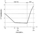
次に、室外熱交換器10の蒸発運転時の各冷媒流通管32,33,34a〜34d,35a〜35dの温度変化について説明する。図3は、蒸発運転時の室外熱交換器の各冷媒流通管の温度変化の一例を示すグラフである。なお、図3に示すデータは、室内温度が20℃、室外温度が7℃(湿球温度6℃)の条件下で測定されたものである。
Next, temperature changes in the
蒸発運転時において、室外熱交換器10の入口となる冷媒配管22には、冷媒として乾き度の小さい気液二相冷媒が供給される。当該気液二相冷媒は、冷媒流通管を通る際に生じる圧力損失が、気相や乾き度の大きい気液二相冷媒に比べて小さいという性質を有する。圧力損失が小さいと、冷媒流通管の温度低下は小さくなる。このため、乾き度の小さい気液二相冷媒が流れる第1熱交換部30では圧力損失を大きくしても、冷媒と空気との温度差を保つことができる。加えて、本第1実施形態においては、比較的圧力損失が大きい乾き度の大きい気液二相冷媒が流れる第2熱交換部31では、圧力損失の増加を抑制している。このために、室外熱交換器10全体として高い熱交換効率を得ることができる。
During the evaporation operation, a gas-liquid two-phase refrigerant having a low dryness is supplied to the
また、本第1実施形態においては、冷媒流通管33を通る気液二相冷媒が冷媒流通管34a〜34dに分配されるので、圧力損失が抑えられ、冷媒流通管の温度低下も抑えられる。さらに、第1熱交換部30を通過後に、冷媒を冷媒流通管34a〜34dに分配しているため、分配する冷媒量のバラつきを小さくできる。これは、乾き度の低い気液二相冷媒を分配するより、乾き度の高い気液二相冷媒を分配する方が、冷媒量のバラつきを小さくできるためである。
In the first embodiment, since the gas-liquid two-phase refrigerant passing through the
また、気液二相冷媒は、冷媒流通34a〜34dを通る過程で、室外ファンから送風される空気と熱交換されて蒸発し、気相冷媒となる。本第1実施形態においては、第2熱交換部31における冷媒の流れ方向が空気の流れ方向と対向するように構成されているので、熱交換が促進され、気相冷媒の温度が大きく上昇する。これにより、室外熱交換器10の出口側に位置する冷媒流通管35a〜35dで過熱度をとった場合においても、冷媒と空気との温度差を大きく保つことができ、高い熱交換効率を得ることができる。
In addition, the gas-liquid two-phase refrigerant exchanges heat with the air blown from the outdoor fan in the process of passing through the
次に、室外熱交換器10の凝縮運転時の動作について説明する。
Next, the operation | movement at the time of the condensation operation | movement of the
凝縮運転が開始されると、冷媒配管24、逆止弁40を通じて、第2熱交換部31に気相冷媒が送られる。この気相冷媒は、第2風下側熱交換部31bの冷媒流通管34a〜34dに分配され、第2風上側熱交換部31aの冷媒流通管35a〜35dに送られる。この過程で、気相冷媒と室外ファンから送風される空気との熱交換が行われ、気相冷媒が凝縮して気液二相冷媒となる。
When the condensation operation is started, the gas-phase refrigerant is sent to the second
その後、冷媒流通管35a〜35dを通る気液二相冷媒は、冷媒流通管38にて合流し、逆止弁43を通過して第1熱交換部31に送られる。この気液二相冷媒は、第1風下側熱交換部30bの冷媒流通管33、第1風上側熱交換部30aの冷媒流通管32を通じて冷媒配管22に送られる。この過程で、気液二相冷媒と室外ファンから送風される空気との熱交換が行われ、気液二相冷媒が凝縮して液相冷媒となる。
Thereafter, the gas-liquid two-phase refrigerant passing through the
次に、室外熱交換器10の凝縮運転時の各冷媒流通管32,33,34a〜34d,35a〜35dの温度変化について説明する。図4は、室外熱交換器の凝縮運転時の各冷媒流通管の温度変化の一例を示すグラフである。なお、図4に示すデータは、室内温度が27℃(湿球温度19℃)、室外温度が35℃の条件下で測定されたものである。
Next, temperature changes in the
凝縮運転時において、室外熱交換器10の入口となる冷媒配管24には、冷媒として気相冷媒が供給される。この気相冷媒は、冷媒流通34a〜34d,35a〜35dを通る過程で、室外ファンから送風される空気と熱交換されて凝縮し、気液二相冷媒となる。本第1実施形態においては、第2熱交換部31における冷媒の流れ方向が空気の流れ方向と対向するように構成されているので、熱交換が促進され、冷媒の温度が大きく低下する。
During the condensation operation, the
また、気液二相冷媒は、冷媒流通33〜32を通る過程で、室外ファンから送風される空気と熱交換されて蒸発し、液相冷媒となる。本第1実施形態においては、第1熱交換部30における冷媒の流れ方向が空気の流れ方向と対向するように構成されているので、熱交換が促進され、液相冷媒の温度が大きく低下する。これにより、室外熱交換器10の出口側に位置する冷媒流通管32で過冷却度をとった場合においても、冷媒と空気との温度差を大きく保つことができ、高い熱交換効率を得ることができる。
In addition, the gas-liquid two-phase refrigerant undergoes heat exchange with the air blown from the outdoor fan in the process of passing through the
本第1実施形態によれば、凝縮運転時において、第1熱交換部30における冷媒の流れと空気の流れとが対向流になっている。また、凝縮運転時と蒸発運転時の両時において、第2熱交換部31における冷媒の流れと空気の流れとが対向流になっている。これにより、高い熱交換効率を得ることができる。また、第2熱交換部31は第1熱交換部30より伝熱面積が大きくなるように構成されている。このため、凝縮運転時と蒸発運転時の両時において、室外熱交換器10の大部分が冷媒の流れと空気の流れとが対向流になっている。これにより、高い熱交換効率を得ることができる。
According to the first embodiment, during the condensing operation, the refrigerant flow and the air flow in the first
また、本第1実施形態によれば、蒸発運転時において、第1熱交換部30における冷媒の流れと空気の流れとが並行流になっている。しかしながら、蒸発運転時において、室外熱交換器10の入口に供給される気液二相冷媒は、流速が遅く、熱交換器内の冷媒流通管を通る際に生じる圧力損失が小さいという性質を有するので、冷媒流通管の温度低下を抑えることができる。これにより、冷媒と空気との温度差を大きく保つことができ、熱交換効率の低下を抑えることができる。当該温度低下を抑えることにより、冷媒流通管32の温度を低くすることができる。これにより、冷媒と空気との温度差を大きく保つことができ、高い熱交換効率を得ることができる。
Further, according to the first embodiment, during the evaporation operation, the refrigerant flow and the air flow in the first
また、本第1実施形態によれば、室外熱交換器10の外部に複数の冷媒流路切り換え装置を設けることなく、高い熱交換効率を得ることができるので、小型化、低コスト化を図ることができる。
In addition, according to the first embodiment, high heat exchange efficiency can be obtained without providing a plurality of refrigerant flow switching devices outside the
また、本第1実施形態によれば、室外熱交換器10が、比較的簡易な部品である冷媒流通管と逆止弁との組み合わせにより構成されているので、小型化、低コスト化を図ることができる。
In addition, according to the first embodiment, the
また、本第1実施形態によれば、第2熱交換部31の冷媒経路数が多いので、圧力損失を低下させることができる。また、第1熱交換部30の冷媒経路数が少ないことにより、1つの冷媒経路に流れる気液二相冷媒の量を増やすことができる。これにより、気液二相冷媒の流速を速くして、熱交換を促進させることができる。
In addition, according to the first embodiment, since the number of refrigerant paths in the second
なお、第2熱交換部31のように冷媒経路数を多くした場合、冷媒の分配や空気の速度分布にバラツキが生じ、熱交換効率が大きく低下してしまうことが起こり得る。
In addition, when the number of refrigerant paths is increased as in the second
これに対して、本第1実施形態によれば、冷媒経路数が少ない第1熱交換部30が、凝縮運転時における冷媒の流れ方向に対して、第2熱交換部31よりも下流に配置されるので、冷媒流通管35a〜35dを通過した冷媒を第1熱交換部30により合流させて均温化することができる。すなわち、本第1実施形態によれば、冷媒の分配や空気の速度分布にバラツキが生じたとしても、熱交換効率が低下することを抑えることができる。
On the other hand, according to the first embodiment, the first
なお、第1熱交換部30は、図2に示すように、第2熱交換部31よりも下方に配置されることが好ましい。この構成によれば、例えば、凝縮運転時において、液相冷媒が重力に従って流れることが可能となり、第1熱交換部30の冷媒流通管32,33内に無駄な液相冷媒が溜まることを抑えることができる。
In addition, it is preferable that the 1st
また、室外熱交換器10の底部と室外機2の底部との間には、霜の溶け残りが発生しやすい。これに対して、第1熱交換部30が第2熱交換部31よりも下方に配置されることで、凝縮運転時に比較的高温の冷媒が流れる第1熱交換部30が室外機2の底部により近い位置に配置されることになるので、室外熱交換器10の底部と室外機2の底部との間に発生した霜の溶け残りを抑えることができる。
Moreover, unmelted frost is likely to occur between the bottom of the
(第2実施形態)
図5は、本発明の第2実施形態に係る空気調和機が備える室外熱交換器の構成を模式的に示す説明図である。本第2実施形態に係る空気調和機が前記第1実施形態に係る空気調和機と異なる点は、室外熱交換器10Aが、室外ファンから送風される空気の流れに対して、風上側、中央、風下側の3列の管配列を有し、第1熱交換部の冷媒流路が風上側よりも風下側の方が多くなっている点である。なお、図5において、実線矢印は、室外熱交換器10Aが蒸発器として使用される蒸発運転時(暖房運転時)の冷媒の流れ方向を示している。また、図5において、破線矢印は、室外熱交換器10Aが凝縮器として使用される凝縮運転時(冷房運転時)の冷媒の流れ方向を示している。(Second Embodiment)
FIG. 5 is an explanatory view schematically showing a configuration of an outdoor heat exchanger provided in the air conditioner according to the second embodiment of the present invention. The difference between the air conditioner according to the second embodiment and the air conditioner according to the first embodiment is that the
図5に示すように、室外熱交換器10Aは、第1熱交換部50と、第2熱交換部51とを備えている。また、第2熱交換部51は第1熱交換部50より伝熱面積が大きくなるように構成されている。
As shown in FIG. 5, the
第1熱交換部50は、凝縮運転時においては、冷媒の流れ方向が空気の流れ方向と対向し、蒸発運転時においては、冷媒の流れ方向が空気の流れ方向と並行であるように構成されている。第1熱交換部50は、蒸発運転時における冷媒の流れ方向に対して、第2熱交換部51よりも上流に配置されている。第2熱交換部51は、凝縮運転時と蒸発運転時の両時において、冷媒の流れ方向が空気の流れ方向と対向するように構成されている。より具体的には、第1熱交換部50及び第2熱交換部51は、以下のように構成されている。
The first
第1熱交換部50は、空気の流れ方向に対して風上に位置する第1風上側熱交換部50aと、空気の流れ方向に対して風下に位置し、第1風上側熱交換部50aよりも冷媒経路数が多い第1風下側熱交換部50cと、第1風上側熱交換部50aと第1風下側熱交換部50cとの間に位置する第1中央熱交換部50bとを備えている。第1風下側熱交換部50aは、冷媒流通管52を備えている。冷媒流通管52は、冷媒配管22と接続されている。第1風下側熱交換部50cは、冷媒流通管53a,53bを備えている。第1中央熱交換部50bは、冷媒流通管52から分岐され、冷媒流通管53a,53bと接続される冷媒流通管を備えている。
The first
第2熱交換部51は、空気の流れ方向に対して風上に位置する第2風上側熱交換部51aと、空気の流れ方向に対して風下に位置する第2風下側熱交換部51cと、第2風上側熱交換部51aと第2風下側熱交換部51cとの間に位置する第2中央熱交換部51bとを備えている。第2風上側熱交換部51aは、6つの冷媒流通管55a〜55fを備えている。第2風下側熱交換部51cは、6つの冷媒流通管54a〜54fを備えている。冷媒流通管54a〜54fと冷媒流通管55a〜55fとがそれぞれ接続されることで、6つの冷媒流路が形成されている。
The second
冷媒流通管54a〜54fには、冷媒流通管36が接続されている。冷媒流通管36は、冷媒配管24と冷媒流通管53a,53bとに接続されている。冷媒流通管55a〜55fには、冷媒流通管37と冷媒流通管38とが接続されている。
A
本第2実施形態によれば、凝縮運転時においては、第1風上側熱交換部50aの冷媒経路数が少ないことにより、1つの冷媒経路に流れる気液二相冷媒の量を増やすことができる。これにより、気液二相冷媒の流速を速くして、熱交換を促進させることができる。また、蒸発運転時においては、第1風下側熱交換部50c及び第1中央熱交換部50bの冷媒経路数が多いことにより、圧力損失を低減させることができる。これにより、冷媒と空気との温度差を大きく保つことが可能となり、熱交換効率を向上させることができる。
According to the second embodiment, during the condensation operation, the amount of the gas-liquid two-phase refrigerant flowing in one refrigerant path can be increased by reducing the number of refrigerant paths in the first upwind
次に、室外熱交換器10Aの蒸発運転時の動作について説明する。
Next, the operation during the evaporation operation of the
蒸発運転が開始されると、冷媒配管22を通じて、第1熱交換部50に気液二相冷媒が送られる。この気液二相冷媒は、第1風上側熱交換部50aの冷媒流通管52、第1風下側熱交換部50cの冷媒流通管53a、53bを通じて冷媒流通管36に送られる。この過程で、気液二相冷媒と室外ファンから送風される空気との熱交換が行われる。
When the evaporation operation is started, the gas-liquid two-phase refrigerant is sent to the first
その後、気液二相冷媒は、逆止弁41を通過して第2熱交換部51に送られる。この気液二相冷媒は、第2風下側熱交換部51cの冷媒流通管54a〜54fに分配され、中央熱交換部51bを介して第2風上側熱交換部51aに送られる。その後、当該分配された気液二相冷媒は、第2風上側熱交換部51aの冷媒流通管55a〜55fを通じて冷媒流通管37に送られる。この過程で、気液二相冷媒と室外ファンから送風される空気との熱交換が行われ、気液二相冷媒が蒸発して気相冷媒となる。当該気相冷媒は、冷媒流通管37で合流し、逆止弁42を通過して冷媒配管24に送られる。
Thereafter, the gas-liquid two-phase refrigerant passes through the
次に、室外熱交換器10Aの蒸発運転時の各冷媒流通管52,53a,53b,54a〜54f,55a〜55fの温度変化について説明する。図6は、蒸発運転時の室外熱交換器の各冷媒流通管の温度変化の一例を示すグラフである。なお、図6に示すデータは、室内温度が20℃、室外温度が7℃(湿球温度6℃)の条件下で測定されたものである。
Next, temperature changes in the
蒸発運転時において、室外熱交換器10Aの入口となる冷媒配管22には、冷媒として乾き度の小さい気液二相冷媒が供給される。当該気液二相冷媒は、冷媒流通管(伝熱管ともいう)を通る際に生じる圧力損失が、気相や乾き度の大きい気液二相冷媒に比べて小さいという性質を有する。圧力損失が小さいと、冷媒流通管の温度低下は小さくなる。このため、乾き度の小さい気液二相冷媒が流れる第1熱交換部50では圧力損失を大きくしても、冷媒と空気との温度差を保つことができる。加えて、本第2実施形態においては、比較的圧力損失が大きい乾き度の大きい気液二相冷媒が流れる第2熱交換部51では、圧力損失の増加を抑制している。このために、室外熱交換器10全体として高い熱交換効率を得ることができる。このために、室外熱交換器10A全体として高い熱交換効率を得ることができる。
During the evaporation operation, a gas-liquid two-phase refrigerant having a low dryness is supplied as a refrigerant to the
また、本第2実施形態においては、冷媒流通管52を通る気液二相冷媒が冷媒流通管53a,53bに分配されるので、圧力損失が抑えられ、冷媒流通管の温度低下も抑えられる。
In the second embodiment, since the gas-liquid two-phase refrigerant passing through the
また、本第2実施形態においては、冷媒流通管36を通る気液二相冷媒が冷媒流通管54a〜54fに分配されるので、圧力損失がより一層抑えられ、冷媒流通管の温度低下もより一層抑えられる。さらに、第1熱交換部50を通過後に、冷媒を冷媒流通管54a〜54fに分配しているため、分配する冷媒量のバラつきを小さくできる。これは、乾き度の低い気液二相冷媒を分配するより、乾き度の高い気液二相冷媒を分配する方が、冷媒量のバラつきを小さくできるためである。
In the second embodiment, since the gas-liquid two-phase refrigerant passing through the
また、気液二相冷媒は、冷媒流通54a〜54fを通る過程で、室外ファンから送風される空気と熱交換されて蒸発し、気相冷媒となる。本第2実施形態においては、第2熱交換部51における冷媒の流れ方向が空気の流れ方向と対向するように構成されているので、熱交換が促進され、気相冷媒の温度が大きく上昇する。これにより、室外熱交換器10Aの出口側に位置する冷媒流通管55a〜55fで過熱度をとった場合においても、冷媒と空気との温度差を大きく保つことができ、高い熱交換効率を得ることができる。
Further, the gas-liquid two-phase refrigerant exchanges heat with the air blown from the outdoor fan in the process of passing through the
本第2実施形態によれば、第1風下側熱交換部50cの冷媒経路数が第1風上側熱交換部50aの冷媒経路数よりも多くなっているので、冷媒と空気との温度差を一層大きく保つことができ、より高い熱交換効率を得ることができる。
According to the second embodiment, since the number of refrigerant paths of the first leeward
なお、本発明は前記実施形態に限定されるものではなく、その他種々の態様で実施できる。例えば、前記では、室外熱交換器10の構成について説明したが、当該構成は室内熱交換器14に適用されてもよい。
In addition, this invention is not limited to the said embodiment, It can implement in another various aspect. For example, the configuration of the
また、前記では、冷媒流通管と逆止弁との組合せにより室外熱交換器10を構成したが、本発明はこれに限定されない。例えば、逆止弁に代えて二方弁を用いてもよい。この場合でも、熱交換器の外部に複数の冷媒流路切り換え装置などを設けることなく、高い熱交換効率を得ることができるので、小型化、低コスト化を図ることができる。
Moreover, although the
なお、前記様々な実施形態のうちの任意の実施形態を適宜組み合わせることにより、それぞれの有する効果を奏するようにすることができる。 It is to be noted that, by appropriately combining any of the various embodiments, the effects possessed by them can be produced.
本発明は、添付図面を参照しながら好ましい実施形態に関連して充分に記載されているが、この技術に熟練した人々にとっては種々の変形や修正は明白である。そのような変形や修正は、添付した請求の範囲による本発明の範囲から外れない限りにおいて、その中に含まれると理解されるべきである。 Although the present invention has been fully described in connection with preferred embodiments with reference to the accompanying drawings, various changes and modifications will be apparent to those skilled in the art. Such changes and modifications are to be understood as being included therein, so long as they do not depart from the scope of the present invention according to the appended claims.
2012年6月18日に出願された日本国特許出願No.2012−136596号の明細書、図面、および特許請求の範囲の開示内容は、全体として参照されて本明細書の中に取り入れられるものである。 Japanese Patent Application No. 1 filed on June 18, 2012. The disclosure of the specification, drawings, and claims of 2012-136596 is hereby incorporated by reference in its entirety.
本発明に係る熱交換器は、従来の構成とは異なる構成により、高い熱交換効率を得ることができるので、小型化、低コスト化が求められる熱交換器、及びそれを備える空気調和機に有用である。 Since the heat exchanger according to the present invention can obtain high heat exchange efficiency by a configuration different from the conventional configuration, a heat exchanger that is required to be downsized and reduced in cost, and an air conditioner including the heat exchanger. Useful.
2 室外機
4 室内機
6 圧縮機
8 四方弁
10,10A 室外熱交換器(熱交換器)
12 膨張弁(減圧装置)
14 室内熱交換器(熱交換器)
16,18,22,24 冷媒配管
20 ストレーナ
26 アキュームレータ
30,50 第1熱交換部
30a,50a 第1風上側熱交換部
30b,50c 第1風下側熱交換部
31,51 第2熱交換部
31a,51a 第2風上側熱交換部
31b,51c 第2風下側熱交換部
32,33,34a〜34d,35a〜35d,36,37,38,53a,53b,54a〜54f,55a〜55f 冷媒流通管
50b 第1中央熱交換部
51b 第2中央熱交換部
40〜43 逆止弁2
12 Expansion valve (pressure reduction device)
14 Indoor heat exchanger (heat exchanger)
16, 18, 22, 24 Refrigerant piping 20
Claims (7)
凝縮運転時においては、冷媒の流れ方向が前記冷媒と熱交換を行うために送風される空気の流れ方向と対向し、蒸発運転時においては、前記冷媒の流れ方向が前記空気の流れ方向と並行であるように構成された第1熱交換部と、
前記凝縮運転時と前記蒸発運転時の両時において、前記冷媒の流れ方向が前記空気の流れ方向と対向するように構成された第2熱交換部と、
を備え、
前記第1熱交換部は、前記蒸発運転時における前記冷媒の流れ方向に対して前記第2熱交換部よりも上流に配置されている、熱交換器。A heat exchanger having a plurality of rows of tube arrangements,
During the condensation operation, the refrigerant flow direction opposes the flow direction of the air blown to exchange heat with the refrigerant, and during the evaporation operation, the refrigerant flow direction is parallel to the air flow direction. A first heat exchange part configured to be
A second heat exchanging unit configured so that the flow direction of the refrigerant faces the flow direction of the air at both the condensation operation and the evaporation operation;
With
The first heat exchange unit is a heat exchanger disposed upstream of the second heat exchange unit with respect to a flow direction of the refrigerant during the evaporation operation.
Priority Applications (1)
| Application Number | Priority Date | Filing Date | Title |
|---|---|---|---|
| JP2014520951A JP6098951B2 (en) | 2012-06-18 | 2013-06-18 | Heat exchanger and air conditioner |
Applications Claiming Priority (4)
| Application Number | Priority Date | Filing Date | Title |
|---|---|---|---|
| JP2012136596 | 2012-06-18 | ||
| JP2012136596 | 2012-06-18 | ||
| JP2014520951A JP6098951B2 (en) | 2012-06-18 | 2013-06-18 | Heat exchanger and air conditioner |
| PCT/JP2013/003792 WO2013190830A1 (en) | 2012-06-18 | 2013-06-18 | Heat exchanger and air conditioner |
Publications (2)
| Publication Number | Publication Date |
|---|---|
| JPWO2013190830A1 true JPWO2013190830A1 (en) | 2016-02-08 |
| JP6098951B2 JP6098951B2 (en) | 2017-03-22 |
Family
ID=49768444
Family Applications (1)
| Application Number | Title | Priority Date | Filing Date |
|---|---|---|---|
| JP2014520951A Active JP6098951B2 (en) | 2012-06-18 | 2013-06-18 | Heat exchanger and air conditioner |
Country Status (3)
| Country | Link |
|---|---|
| JP (1) | JP6098951B2 (en) |
| CN (1) | CN104350341B (en) |
| WO (1) | WO2013190830A1 (en) |
Families Citing this family (7)
| Publication number | Priority date | Publication date | Assignee | Title |
|---|---|---|---|---|
| JPWO2018025305A1 (en) * | 2016-08-01 | 2019-03-22 | 三菱電機株式会社 | Air conditioner |
| CN109477669B (en) | 2016-08-09 | 2020-09-22 | 三菱电机株式会社 | Heat exchanger and refrigeration cycle device provided with same |
| JP6946105B2 (en) * | 2017-08-02 | 2021-10-06 | 三菱重工サーマルシステムズ株式会社 | Heat exchanger |
| EP3734190B1 (en) * | 2017-12-25 | 2024-02-21 | Mitsubishi Electric Corporation | Heat exchanger and refrigeration cycle device |
| JP7275372B2 (en) * | 2020-02-27 | 2023-05-17 | 三菱電機株式会社 | Heat source side unit heat exchanger and heat pump device equipped with the heat exchanger |
| JP6918257B1 (en) * | 2021-01-28 | 2021-08-11 | 日立ジョンソンコントロールズ空調株式会社 | Air conditioner and heat exchanger |
| JP2023021486A (en) * | 2021-08-02 | 2023-02-14 | パナソニックIpマネジメント株式会社 | Refrigeration cycle device |
Citations (10)
| Publication number | Priority date | Publication date | Assignee | Title |
|---|---|---|---|---|
| JPS616179U (en) * | 1984-06-15 | 1986-01-14 | 三菱電機株式会社 | Refrigeration equipment |
| JPH07151425A (en) * | 1993-11-30 | 1995-06-16 | Sanyo Electric Co Ltd | Refrigerator |
| JPH09196489A (en) * | 1996-01-19 | 1997-07-31 | Fujitsu General Ltd | Refrigeration cycle for air conditioner |
| JPH10318618A (en) * | 1997-05-20 | 1998-12-04 | Fujitsu General Ltd | Air conditioner |
| JP2002228273A (en) * | 2001-02-05 | 2002-08-14 | Mitsubishi Electric Corp | Air conditioner |
| JP2007278676A (en) * | 2006-04-12 | 2007-10-25 | Matsushita Electric Ind Co Ltd | Heat exchanger |
| JP2008116135A (en) * | 2006-11-06 | 2008-05-22 | Daikin Ind Ltd | Heat exchanger and refrigeration device |
| JP2009109064A (en) * | 2007-10-29 | 2009-05-21 | Hitachi Appliances Inc | Air conditioner |
| WO2010146852A1 (en) * | 2009-06-19 | 2010-12-23 | ダイキン工業株式会社 | Ceiling-mounted air conditioning unit |
| JP2011112333A (en) * | 2009-11-30 | 2011-06-09 | Mitsubishi Electric Corp | Air conditioner and operation method of the air conditioner |
Family Cites Families (1)
| Publication number | Priority date | Publication date | Assignee | Title |
|---|---|---|---|---|
| JPH0949667A (en) * | 1995-08-07 | 1997-02-18 | Fujitsu General Ltd | Air conditioning equipment |
-
2013
- 2013-06-18 JP JP2014520951A patent/JP6098951B2/en active Active
- 2013-06-18 WO PCT/JP2013/003792 patent/WO2013190830A1/en active Application Filing
- 2013-06-18 CN CN201380029882.8A patent/CN104350341B/en active Active
Patent Citations (10)
| Publication number | Priority date | Publication date | Assignee | Title |
|---|---|---|---|---|
| JPS616179U (en) * | 1984-06-15 | 1986-01-14 | 三菱電機株式会社 | Refrigeration equipment |
| JPH07151425A (en) * | 1993-11-30 | 1995-06-16 | Sanyo Electric Co Ltd | Refrigerator |
| JPH09196489A (en) * | 1996-01-19 | 1997-07-31 | Fujitsu General Ltd | Refrigeration cycle for air conditioner |
| JPH10318618A (en) * | 1997-05-20 | 1998-12-04 | Fujitsu General Ltd | Air conditioner |
| JP2002228273A (en) * | 2001-02-05 | 2002-08-14 | Mitsubishi Electric Corp | Air conditioner |
| JP2007278676A (en) * | 2006-04-12 | 2007-10-25 | Matsushita Electric Ind Co Ltd | Heat exchanger |
| JP2008116135A (en) * | 2006-11-06 | 2008-05-22 | Daikin Ind Ltd | Heat exchanger and refrigeration device |
| JP2009109064A (en) * | 2007-10-29 | 2009-05-21 | Hitachi Appliances Inc | Air conditioner |
| WO2010146852A1 (en) * | 2009-06-19 | 2010-12-23 | ダイキン工業株式会社 | Ceiling-mounted air conditioning unit |
| JP2011112333A (en) * | 2009-11-30 | 2011-06-09 | Mitsubishi Electric Corp | Air conditioner and operation method of the air conditioner |
Also Published As
| Publication number | Publication date |
|---|---|
| CN104350341B (en) | 2016-07-20 |
| WO2013190830A1 (en) | 2013-12-27 |
| JP6098951B2 (en) | 2017-03-22 |
| CN104350341A (en) | 2015-02-11 |
Similar Documents
| Publication | Publication Date | Title |
|---|---|---|
| JP6098951B2 (en) | Heat exchanger and air conditioner | |
| JP5991989B2 (en) | Refrigeration air conditioner | |
| JP6045695B2 (en) | Air conditioner | |
| JP4922669B2 (en) | Air conditioner and heat exchanger for air conditioner | |
| WO2019239446A1 (en) | Air conditioner outdoor unit and air conditioner | |
| KR100697087B1 (en) | Air-Condition | |
| JP6715929B2 (en) | Refrigeration cycle device and air conditioner including the same | |
| JP5805567B2 (en) | Refrigeration cycle and refrigeration showcase | |
| JP2014105890A (en) | Refrigeration cycle device and hot-water generating device including the same | |
| JPWO2018029817A1 (en) | Refrigeration cycle device | |
| CN110300879A (en) | Heat exchanger and air conditioner | |
| JP5403039B2 (en) | Air conditioner | |
| JP5677220B2 (en) | Refrigeration cycle equipment | |
| JP2019090595A (en) | Cooling device | |
| JP6242289B2 (en) | Refrigeration cycle equipment | |
| JP6298992B2 (en) | Air conditioner | |
| JP2019215161A (en) | Outdoor machine of air conditioner, and air conditioner | |
| US20120137723A1 (en) | Air conditioner | |
| JP2008267731A (en) | Air-conditioning device | |
| JP2005337577A (en) | Refrigerating device | |
| JP2005337577A5 (en) | ||
| JP2012063083A (en) | Heat source unit | |
| TWI765270B (en) | Dehumidifier | |
| KR101323527B1 (en) | Air conditioner | |
| JP2007127333A (en) | Air conditioner |
Legal Events
| Date | Code | Title | Description |
|---|---|---|---|
| A521 | Request for written amendment filed |
Free format text: JAPANESE INTERMEDIATE CODE: A523 Effective date: 20160602 |
|
| A621 | Written request for application examination |
Free format text: JAPANESE INTERMEDIATE CODE: A621 Effective date: 20160602 |
|
| TRDD | Decision of grant or rejection written | ||
| A01 | Written decision to grant a patent or to grant a registration (utility model) |
Free format text: JAPANESE INTERMEDIATE CODE: A01 Effective date: 20170207 |
|
| A61 | First payment of annual fees (during grant procedure) |
Free format text: JAPANESE INTERMEDIATE CODE: A61 Effective date: 20170209 |
|
| R151 | Written notification of patent or utility model registration |
Ref document number: 6098951 Country of ref document: JP Free format text: JAPANESE INTERMEDIATE CODE: R151 |