JP7275372B2 - Heat source side unit heat exchanger and heat pump device equipped with the heat exchanger - Google Patents
Heat source side unit heat exchanger and heat pump device equipped with the heat exchanger Download PDFInfo
- Publication number
- JP7275372B2 JP7275372B2 JP2022502686A JP2022502686A JP7275372B2 JP 7275372 B2 JP7275372 B2 JP 7275372B2 JP 2022502686 A JP2022502686 A JP 2022502686A JP 2022502686 A JP2022502686 A JP 2022502686A JP 7275372 B2 JP7275372 B2 JP 7275372B2
- Authority
- JP
- Japan
- Prior art keywords
- heat
- heat transfer
- transfer tube
- heat exchanger
- refrigerant
- Prior art date
- Legal status (The legal status is an assumption and is not a legal conclusion. Google has not performed a legal analysis and makes no representation as to the accuracy of the status listed.)
- Active
Links
Images


Classifications
-
- F—MECHANICAL ENGINEERING; LIGHTING; HEATING; WEAPONS; BLASTING
- F25—REFRIGERATION OR COOLING; COMBINED HEATING AND REFRIGERATION SYSTEMS; HEAT PUMP SYSTEMS; MANUFACTURE OR STORAGE OF ICE; LIQUEFACTION SOLIDIFICATION OF GASES
- F25B—REFRIGERATION MACHINES, PLANTS OR SYSTEMS; COMBINED HEATING AND REFRIGERATION SYSTEMS; HEAT PUMP SYSTEMS
- F25B39/00—Evaporators; Condensers
- F25B39/02—Evaporators
-
- F—MECHANICAL ENGINEERING; LIGHTING; HEATING; WEAPONS; BLASTING
- F25—REFRIGERATION OR COOLING; COMBINED HEATING AND REFRIGERATION SYSTEMS; HEAT PUMP SYSTEMS; MANUFACTURE OR STORAGE OF ICE; LIQUEFACTION SOLIDIFICATION OF GASES
- F25B—REFRIGERATION MACHINES, PLANTS OR SYSTEMS; COMBINED HEATING AND REFRIGERATION SYSTEMS; HEAT PUMP SYSTEMS
- F25B41/00—Fluid-circulation arrangements
- F25B41/40—Fluid line arrangements
- F25B41/42—Arrangements for diverging or converging flows, e.g. branch lines or junctions
-
- F—MECHANICAL ENGINEERING; LIGHTING; HEATING; WEAPONS; BLASTING
- F25—REFRIGERATION OR COOLING; COMBINED HEATING AND REFRIGERATION SYSTEMS; HEAT PUMP SYSTEMS; MANUFACTURE OR STORAGE OF ICE; LIQUEFACTION SOLIDIFICATION OF GASES
- F25B—REFRIGERATION MACHINES, PLANTS OR SYSTEMS; COMBINED HEATING AND REFRIGERATION SYSTEMS; HEAT PUMP SYSTEMS
- F25B47/00—Arrangements for preventing or removing deposits or corrosion, not provided for in another subclass
- F25B47/006—Arrangements for preventing or removing deposits or corrosion, not provided for in another subclass for preventing frost
-
- F—MECHANICAL ENGINEERING; LIGHTING; HEATING; WEAPONS; BLASTING
- F28—HEAT EXCHANGE IN GENERAL
- F28D—HEAT-EXCHANGE APPARATUS, NOT PROVIDED FOR IN ANOTHER SUBCLASS, IN WHICH THE HEAT-EXCHANGE MEDIA DO NOT COME INTO DIRECT CONTACT
- F28D1/00—Heat-exchange apparatus having stationary conduit assemblies for one heat-exchange medium only, the media being in contact with different sides of the conduit wall, in which the other heat-exchange medium is a large body of fluid, e.g. domestic or motor car radiators
- F28D1/02—Heat-exchange apparatus having stationary conduit assemblies for one heat-exchange medium only, the media being in contact with different sides of the conduit wall, in which the other heat-exchange medium is a large body of fluid, e.g. domestic or motor car radiators with heat-exchange conduits immersed in the body of fluid
- F28D1/04—Heat-exchange apparatus having stationary conduit assemblies for one heat-exchange medium only, the media being in contact with different sides of the conduit wall, in which the other heat-exchange medium is a large body of fluid, e.g. domestic or motor car radiators with heat-exchange conduits immersed in the body of fluid with tubular conduits
- F28D1/0408—Multi-circuit heat exchangers, e.g. integrating different heat exchange sections in the same unit or heat exchangers for more than two fluids
- F28D1/0417—Multi-circuit heat exchangers, e.g. integrating different heat exchange sections in the same unit or heat exchangers for more than two fluids with particular circuits for the same heat exchange medium, e.g. with the heat exchange medium flowing through sections having different heat exchange capacities or for heating/cooling the heat exchange medium at different temperatures
-
- F—MECHANICAL ENGINEERING; LIGHTING; HEATING; WEAPONS; BLASTING
- F28—HEAT EXCHANGE IN GENERAL
- F28F—DETAILS OF HEAT-EXCHANGE AND HEAT-TRANSFER APPARATUS, OF GENERAL APPLICATION
- F28F9/00—Casings; Header boxes; Auxiliary supports for elements; Auxiliary members within casings
- F28F9/02—Header boxes; End plates
- F28F9/026—Header boxes; End plates with static flow control means, e.g. with means for uniformly distributing heat exchange media into conduits
- F28F9/027—Header boxes; End plates with static flow control means, e.g. with means for uniformly distributing heat exchange media into conduits in the form of distribution pipes
- F28F9/0275—Header boxes; End plates with static flow control means, e.g. with means for uniformly distributing heat exchange media into conduits in the form of distribution pipes with multiple branch pipes
-
- F—MECHANICAL ENGINEERING; LIGHTING; HEATING; WEAPONS; BLASTING
- F28—HEAT EXCHANGE IN GENERAL
- F28D—HEAT-EXCHANGE APPARATUS, NOT PROVIDED FOR IN ANOTHER SUBCLASS, IN WHICH THE HEAT-EXCHANGE MEDIA DO NOT COME INTO DIRECT CONTACT
- F28D21/00—Heat-exchange apparatus not covered by any of the groups F28D1/00 - F28D20/00
- F28D2021/0019—Other heat exchangers for particular applications; Heat exchange systems not otherwise provided for
- F28D2021/0068—Other heat exchangers for particular applications; Heat exchange systems not otherwise provided for for refrigerant cycles
- F28D2021/0071—Evaporators
Description
本開示は、熱交換ユニットの最下部で凍結する氷の成長を抑制できる熱源側ユニットの熱交換器及び該熱交換器を備えたヒートポンプ装置に関するものである。 The present disclosure relates to a heat exchanger of a heat source side unit capable of suppressing the growth of ice frozen at the bottom of the heat exchange unit, and a heat pump device including the heat exchanger.
ヒートポンプ装置の熱源側ユニットは、空気と冷媒との間で熱交換を行わせる熱交換器を備えている。熱交換器は、多数の伝熱管で構成された熱交換ユニットを備えている。熱交ユニットは、風上側と風下側に配置して2列とした構成が一般的である。しかし、最近では、熱交換効率を高めるために、熱交ユニットを風路方向に3列以上並べた構成が利用されている。 A heat source side unit of a heat pump device includes a heat exchanger that exchanges heat between air and a refrigerant. The heat exchanger has a heat exchange unit composed of a large number of heat transfer tubes. The heat exchanger units are generally arranged in two rows on the windward side and the leeward side. However, recently, in order to improve the heat exchange efficiency, a configuration in which three or more rows of heat exchange units are arranged in the direction of the air passage is used.
そして、ヒートポンプ装置の熱源側ユニットは、蒸発器として使用される場合、冷媒の蒸発温度が周囲の空気温度に比べて低くなるため、空気中の水分がフィンの表面に結露し、その結露水がフィンを伝って熱交換器の下部及び筐体の底板上に滞留する。そして、滞留した結露水は、外気が氷点下となると凍結するおそれがある。凍結した氷は、時間を追うごとに成長し、熱交換器の下部を損傷させるおそれがある。そのため、熱源側ユニットでは、凍結した氷を解氷させ、氷の成長を抑制できる構成とすることが望ましい。 When the heat source side unit of the heat pump device is used as an evaporator, the evaporation temperature of the refrigerant becomes lower than the temperature of the surrounding air. It travels along the fins and stays on the lower part of the heat exchanger and the bottom plate of the housing. The accumulated dew condensation water may freeze when the temperature of the outside air drops below freezing. Frozen ice grows over time and can damage the lower portion of the heat exchanger. Therefore, it is desirable that the heat source side unit has a configuration capable of thawing the frozen ice and suppressing the growth of the ice.
例えば特許文献1に開示された冷凍装置の熱源側ユニットの熱交換器は、多数のフィンと、上下方向に並び第1列を形成する複数の第1伝熱管と、上下方向に並び第2列を形成する複数の第2伝熱管と、上下方向に並び第3列を形成する複数の第3伝熱管と、液側接続管と、ガス側接続管と、冷媒を分流させる分流器と、を有する構成である。第1伝熱管は、外気の流れる風上側に位置する。第3伝熱管は、外気の流れる風下側に位置する。第2伝熱管は、第1伝熱管と第3伝熱管との間に位置している。 For example, the heat exchanger of the heat source side unit of the refrigeration apparatus disclosed in Patent Document 1 includes a large number of fins, a plurality of first heat transfer tubes arranged in the vertical direction and forming the first row, and a second row arranged in the vertical direction. a plurality of second heat transfer tubes that form a third row, a plurality of third heat transfer tubes arranged in a vertical direction, a liquid side connection pipe, a gas side connection pipe, and a flow divider that divides the refrigerant flow; It is a configuration with The first heat transfer tube is positioned on the windward side where outside air flows. The third heat transfer tube is positioned on the leeward side where outside air flows. The second heat transfer tube is positioned between the first heat transfer tube and the third heat transfer tube.
第1列の最下部に位置する第1伝熱管、第2列の最下部に位置する第2伝熱管、及び第3列の最下部に位置する第3伝熱管は、互いに接続されて第1流路を形成している。液側接続管は、第1列の最下部に位置する第1伝熱管に接続されている。分流器は、第3列の最下部に位置する第3伝熱管に接続されている。熱交換器が蒸発器として機能する場合、液側接続管から比較的高温の冷媒が第1伝熱管へ流入し、第2伝熱管、第3伝熱管を通って分流器へと流れる。分流器は、液側接続管から第1流路に流れ、第1流路を出た冷媒を4つの分岐管に分流させる。第1流路を形成する第1伝熱管、第2伝熱管及び第3伝熱管を除く、他の第1伝熱管、第2伝熱管及び第3伝熱管は、複数の分岐管からそれぞれ出た冷媒が流れる4つの分岐流路を形成している。4つの分岐流路から流れ出た冷媒は、ガス側ヘッダへ流入して合流した後、ガス側接続管へと流れ出る。 The first heat transfer tube positioned at the bottom of the first row, the second heat transfer tube positioned at the bottom of the second row, and the third heat transfer tube positioned at the bottom of the third row are connected to each other to form the first heat transfer tube. forming a flow path. The liquid-side connecting pipe is connected to the first heat transfer pipe positioned at the bottom of the first row. The flow divider is connected to the third heat transfer tube located at the bottom of the third row. When the heat exchanger functions as an evaporator, relatively high-temperature refrigerant flows from the liquid-side connecting pipe into the first heat transfer pipe, passes through the second heat transfer pipe and the third heat transfer pipe, and flows to the flow splitter. The flow divider divides the refrigerant flowing from the liquid-side connecting pipe to the first flow path and exiting the first flow path into the four branch pipes. Except for the first heat transfer tube, the second heat transfer tube and the third heat transfer tube forming the first flow path, the other first heat transfer tube, the second heat transfer tube and the third heat transfer tube exit from the plurality of branch tubes, respectively. It forms four branch channels through which the coolant flows. The refrigerant flowing out from the four branched flow paths flows into the gas side header, merges, and then flows out to the gas side connection pipe.
上記特許文献1の熱交換器では、各列の最下部に位置する第1伝熱管、第2伝熱管及び第3伝熱管が互いに接続されて1本の流路で構成されており、液側接続管から比較的高温の冷媒が第1伝熱管へ流入し、第2伝熱管、第3伝熱管を通って分流器へと流れる。一般に、熱交換器の最下部に位置する伝熱管を流れる冷媒の温度が0℃よりも高ければ、熱交換器の凍結を抑制することが可能である。しかし、この熱交換器では、液側接続管から流入する比較的高温の冷媒が、第1伝熱管から第3伝熱管へ流れる際に配管の圧損と熱交換とによって冷媒温度が低下するため、十分な解氷効果が得られないおそれがある。 In the heat exchanger of Patent Document 1, the first heat transfer tube, the second heat transfer tube, and the third heat transfer tube located at the bottom of each row are connected to each other to form one flow path, and the liquid side A relatively high-temperature refrigerant flows from the connection pipe into the first heat transfer pipe, passes through the second heat transfer pipe and the third heat transfer pipe, and flows to the flow divider. In general, freezing of the heat exchanger can be suppressed if the temperature of the refrigerant flowing through the heat transfer tube positioned at the bottom of the heat exchanger is higher than 0°C. However, in this heat exchanger, when the relatively high-temperature refrigerant flowing from the liquid-side connecting pipe flows from the first heat transfer pipe to the third heat transfer pipe, the refrigerant temperature decreases due to pressure loss and heat exchange in the pipes. A sufficient deicing effect may not be obtained.
本開示は、上記のような課題を解決するためになされたもので、熱交換器が蒸発器として機能した際に、熱交換ユニットの最下部で凍結する氷を解氷させ、氷の成長を抑制できる、熱源側ユニットの熱交換器及び該熱交換器を備えたヒートポンプ装置を提供することを目的とする。 The present disclosure has been made to solve the above problems, and when the heat exchanger functions as an evaporator, the ice frozen at the bottom of the heat exchange unit is thawed to promote the growth of the ice. An object of the present invention is to provide a heat exchanger of a heat source side unit and a heat pump device equipped with the heat exchanger, which can suppress heat generation.
本開示に係る熱源側ユニットの熱交換器は、上下方向に並ぶ複数の伝熱管で構成された伝熱管群が風路方向に少なくとも3列以上設けられた熱交換ユニットと、液相又は気液二相の冷媒の出入口となる液側接続管と、前記熱交換ユニットを構成する複数の冷媒流路に冷媒を分配する分配器と、を有し、前記熱交換ユニットは、前記伝熱管群のうち少なくとも2列の伝熱管群において、該伝熱管群の最下部に位置する伝熱管の一端に前記液側接続管が接続され、他端に前記分配器が接続されているものである。 The heat exchanger of the heat source side unit according to the present disclosure includes a heat exchange unit in which at least three rows of heat transfer tube groups each composed of a plurality of heat transfer tubes arranged in the vertical direction are provided in the air passage direction, and a liquid phase or gas-liquid A liquid-side connecting pipe serving as an inlet and outlet for two-phase refrigerant, and a distributor for distributing the refrigerant to a plurality of refrigerant flow paths constituting the heat exchange unit, wherein the heat exchange unit is connected to the heat transfer tube group. In at least two rows of the heat transfer tube groups, one end of the heat transfer tube positioned at the bottom of the heat transfer tube group is connected to the liquid side connecting pipe, and the other end is connected to the distributor.
本開示に係るヒートポンプ装置は、圧縮機、負荷側熱交換器、膨張機構、上記熱源側ユニットの熱交換器が、配管で順次に接続されて冷媒が循環する冷媒回路を備えたものである。 A heat pump apparatus according to the present disclosure includes a refrigerant circuit in which a compressor, a load-side heat exchanger, an expansion mechanism, and the heat exchanger of the heat source-side unit are sequentially connected by pipes to circulate the refrigerant.
本開示の熱源側ユニットの熱交換器及び該熱交換器を備えたヒートポンプ装置によれば、少なくとも2列の伝熱管群において、該伝熱管群の少なくとも最下部に位置する伝熱管の一端に液側接続管が接続され、他端に分配器が接続されている。よって、熱交換器が蒸発器として機能した際に、液側接続管から流入する比較的高温の冷媒を、最下部に位置する各伝熱管に流入させることができるため、熱交換ユニットの最下部で凍結する氷の成長を抑制できる。 According to the heat exchanger of the heat source side unit and the heat pump device equipped with the heat exchanger of the present disclosure, in at least two rows of heat transfer tube groups, liquid is supplied to one end of the heat transfer tube positioned at least at the bottom of the heat transfer tube group. A side connection pipe is connected, and a distributor is connected to the other end. Therefore, when the heat exchanger functions as an evaporator, the relatively high-temperature refrigerant flowing from the liquid-side connecting pipe can be caused to flow into each heat transfer tube located at the bottom. can suppress the growth of frozen ice.
以下、図面を参照して、本開示の実施の形態について説明する。なお、各図中、同一又は相当する部分には、同一符号を付して、その説明を適宜省略又は簡略化する。また、各図に記載の構成について、その形状、大きさ、及び配置等は、適宜変更することができる。 Embodiments of the present disclosure will be described below with reference to the drawings. In each figure, the same or corresponding parts are denoted by the same reference numerals, and the description thereof will be omitted or simplified as appropriate. Further, the shape, size, arrangement, etc. of the configuration described in each drawing can be changed as appropriate.
実施の形態1.
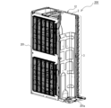
図1は、本実施の形態1に係るヒートポンプ装置の冷媒回路図である。図2は、本実施の形態1に係るヒートポンプ装置の熱源側ユニットであって、構成要素を一部省略した状態で示した斜視図である。Embodiment 1.
FIG. 1 is a refrigerant circuit diagram of a heat pump device according to Embodiment 1. FIG. FIG. 2 is a perspective view of the heat source side unit of the heat pump device according to Embodiment 1, with some constituent elements omitted.
本実施の形態1に係るヒートポンプ装置100は、図1に示すように、熱源側ユニット200と、負荷側ユニット300と、を備えており、例えば空調又は給湯等を行うものである。そして、ヒートポンプ装置100は、圧縮機10、流路切替装置11、熱源側熱交換器12、膨張機構13及び負荷側熱交換器14が、ガス側配管15と液側配管16とにより順次に接続され、冷媒が循環する冷媒回路400を有している。圧縮機10、流路切替装置11、熱源側熱交換器12及び膨張機構13は、熱源側ユニット200に設けられている。負荷側熱交換器14は、負荷側ユニット300に設けられている。
As shown in FIG. 1, the
熱源側ユニット200は、図1及び図2に示すように、外郭を形成する筐体201の内部に、圧縮機10、流路切替装置11、熱源側熱交換器12及び膨張機構13が収容されている。圧縮機10及び熱源側熱交換器12は、筐体201の底板201aの上面に設けられている。
As shown in FIGS. 1 and 2, the heat
圧縮機10は、吸入した冷媒を圧縮し、高温高圧の状態にして吐出するものである。圧縮機10は、一例として、運転容量を可変させることが可能とした構成であり、インバータにより制御されるモータによって駆動される容積式圧縮機である。
The
流路切替装置11は、一例として四方弁であり、冷媒の流路を切り換える機能を有するものである。具体的には、流路切替装置11は、熱源側熱交換器12が凝縮器として機能する場合、圧縮機10の冷媒吐出側と熱源側熱交換器12のガス側とを接続するとともに、圧縮機10の冷媒吸入側と負荷側熱交換器14のガス側とを接続するように冷媒流路を切り換える。また、流路切替装置11は、熱源側熱交換器12が蒸発器として機能する場合、圧縮機10の冷媒吐出側と負荷側熱交換器14のガス側とを接続するとともに、圧縮機10の冷媒吸入側と熱源側熱交換器12のガス側とを接続するように冷媒流路を切り換える。なお、流路切替装置11は、例えば二方弁又は三方弁を組み合わせて構成してもよい。
The
熱源側熱交換器12は、例えば冷房運転時には凝縮器として機能し、圧縮機10から吐出された冷媒と空気との間で熱交換を行わせるものである。また、熱源側熱交換器12は、例えば暖房運転時には蒸発器として機能し、膨張機構13から流出した冷媒と空気との間で熱交換を行わせるものである。熱源側熱交換器12は、送風機によって室外空気を吸い込み、冷媒との間で熱交換した空気を室外に排出する。
The heat source
膨張機構13は、冷媒回路内を流れる冷媒を減圧して膨張させるものであり、一例として開度が可変に制御される電子膨張弁で構成される。
The
負荷側熱交換器14は、例えば冷房運転時には蒸発器として機能し、膨張機構13から流出した冷媒と空気との間で熱交換を行わせるものである。また、負荷側熱交換器14は、例えば暖房運転時には凝縮器として機能し、圧縮機10から吐出された冷媒と空気との間で熱交換を行わせるものである。負荷側熱交換器14は、送風機によって室内空気を吸い込み、冷媒との間で熱交換した空気を室内に供給する。
The load-
次に、図2を参照しつつ、図3に基づいて熱源側熱交換器12の構成を説明する。図3は、本実施の形態1に係るヒートポンプ装置の熱源側熱交換器を模式的に示した説明図である。図3中に示す白抜き矢印は風路方向Xを示している。
Next, the configuration of the heat source
熱源側熱交換器12は、図3に示すように、上下方向に並ぶ複数の伝熱管3で構成された伝熱管群(3A~3C)が風路方向Xに3列設けられた熱交換ユニット1と、熱交換ユニット1を構成する複数の冷媒流路(4a~4c)に冷媒を分配する分配器5と、液相又は気液二相の冷媒の出入口となる液側接続管6と、を有している。
As shown in FIG. 3, the heat source
熱交換ユニット1は、図2及び図3に示すように、複数枚のフィン2と、上下方向に並ぶ複数の伝熱管3で構成された伝熱管群(3A~3C)と、を備えたフィンチューブ型(クロスフィン型)である。フィン2は、例えばアルミニウム合金等の金属材で形成されており、伝熱管3に接して伝熱面積を増大させるものである。フィン2は、板状の面が略平行となるように風路方向Xと略直交する方向に間隔をあけて並列に配置されている。
As shown in FIGS. 2 and 3, the heat exchange unit 1 includes a plurality of
伝熱管群(3A~3C)は、風下側から順に配置された第1列伝熱管群3A、第2列伝熱管群3B及び第3列伝熱管群3Cを有し、風路方向Xに沿って3列で構成されている。第1列伝熱管群3Aは、上下方向に並ぶ複数の伝熱管(30a~30e)で構成されている。第2列伝熱管群3Bは、上下方向に並ぶ複数の伝熱管(31a~31e)で構成されている。第3列伝熱管群3Cは、上下方向に並ぶ複数の伝熱管(32a~32e)で構成されている。なお、伝熱管群(3A~3C)は、風路方向Xに3列以上設けてもよい。また、図示の便宜上、各列の伝熱管を5つのみ記載したが、実際には5つ以上の伝熱管で構成されている。
The heat transfer tube groups (3A to 3C) have a first row heat
伝熱管3は、例えばアルミニウム合金等の金属材で形成されており、内部に冷媒を通す流路が形成されている。伝熱管群(3A~3C)は、第1列伝熱管群3Aと第3列伝熱管群3Cの最下部に位置する伝熱管30a及び32aの一端に液側接続管6が接続され、他端に分配器5が接続されている。図示例では、第1列伝熱管群3Aの最下部に位置する伝熱管30aと、第2列伝熱管群3Bの最下部に位置する伝熱管31aとが接続されており、伝熱管30aに液側接続管6が接続され、伝熱管31aに分配器5が接続されている。第3列伝熱管群3Cの最下部に位置する伝熱管32aは、一端に液側接続管6が接続され、他端に分配器5が接続されている。
The
熱交換ユニット1では、伝熱管群(3A~3C)の最下部に位置する伝熱管(30a、31a、32a)を除き、風路方向Xにおいて隣り合う各列の伝熱管が互いに接続されており、上下方向に複数の冷媒流路(4a~4c)を形成している。各冷媒流路(4a~4c)は、第3列伝熱管群3Cの各伝熱管(32b~32e)が、分配器5にそれぞれ接続されており、第1列伝熱管群3Aの各伝熱管(30b~30e)がガス側配管15にそれぞれ接続されている。なお、第1列伝熱管群3Aの各伝熱管(30b~30e)と、ガス側配管15とは、ガス接続管を介して接続してもよい。
In the heat exchange unit 1, except for the heat transfer tubes (30a, 31a, 32a) positioned at the bottom of the heat transfer tube groups (3A to 3C), heat transfer tubes in adjacent rows in the airflow direction X are connected to each other. , a plurality of coolant channels (4a to 4c) are formed in the vertical direction. In each refrigerant flow path (4a-4c), each heat transfer tube (32b-32e) of the third row heat
なお、熱交換ユニット1は、2列の伝熱管群(3A~3C)において、伝熱管群(3A~3C)の少なくとも最下部に位置する伝熱管(30a~32a)の一端に液側接続管6が接続され、他端に分配器5が接続されていればよく、図示した構成に限定されない。図示することは省略したが、例えば、熱交換ユニット1は、第1列伝熱管群3Aの最下部に位置する伝熱管30aの一端と、第2列伝熱管群3Bの最下部に位置する伝熱管30bの一端に、液側接続管6が接続され、該伝熱管30aの他端と、該伝熱管30bの他端に、分配器5が接続された構成でもよい。また、第1列伝熱管群3Aの最下部に位置する伝熱管30aは、第2列伝熱管群3Bの最下部に位置する伝熱管31aと必ずしも接続する必要はなく、一端に液側接続管6が接続され、他端に分配器5が接続された構成としてもよい。
In the heat exchange unit 1, in the two rows of heat transfer tube groups (3A to 3C), a liquid
また、図示することは省略したが、熱交換ユニット1は、最下部の伝熱管(30a、31a、32a)と、該最下部から2番目に位置する伝熱管(30b、31b、32b)又は該最下部から3番目に位置する伝熱管(30c、31c、32c)のそれぞれに、液側接続管6と分配器5を接続した構成でもよい。或いは、熱交換ユニット1は、最下部から3番目までのすべての伝熱管(30a~30c、31a~31c、32a~32c)のそれぞれに、液側接続管6と分配器5を接続した構成としてもよい。この場合、伝熱管ごとに、液側接続管6と分配器5を接続した構成でもよいし、上下方向又は風路方向Xに隣り合う伝熱管同士を接続し、接続した組の伝熱管に液側接続管6と分配器5を接続した構成でもよい。なお、最下部から2番目及び3番目に位置する伝熱管について説明したが、最下部から4番目以上に位置する伝熱管でも同様に実施できる。
Although not shown, the heat exchange unit 1 includes the lowermost heat transfer tubes (30a, 31a, 32a) and the second lowest heat transfer tubes (30b, 31b, 32b) or the A configuration in which the liquid
液側接続管6は、液側配管16と伝熱管(30a、32a)とを接続するものである。液側接続管6は、例えば2分岐管で構成されている。なお、液側接続管6は、液側配管16の一部として構成してもよいし、液側配管16とは別部材として構成してもよい。
The liquid
分配器5は、分配器本体50と、分配器本体50と伝熱管(30a、32a)とを接続する流入管51と、分配器本体50にそれぞれ接続された複数本の細管52と、を有している。細管52は、例えばキャピラリーチューブで構成されている。細管52は、第3列伝熱管群3Cの伝熱管(32a~32e)のうち、最下部を除く伝熱管(32b~32e)の一端にそれぞれ接続されている。流入管51を介して分配器本体50に流入した冷媒は、分配器本体50で各細管52に分配され、細管52で減圧された後、各冷媒経路(4a~4c)に流入する。なお、分配器5は、図示した構成に限定されず、熱交換ユニット1を構成する複数の冷媒流路(4a~4c)に冷媒を分配することができれば、他の形態でもよい。
The
ここで、ヒートポンプ装置100の熱源側ユニット200は、蒸発器として使用される場合、冷媒の蒸発温度が周囲の空気温度に比べて低くなるため、空気中の水分がフィン2の表面に結露し、その結露水がフィン2を伝って熱交換器12の下部及び筐体201の底板201aの上面に滞留する。そして、滞留した結露水は、外気が氷点下となると凍結するおそれがある。凍結した氷は、時間を追うごとに成長し、熱交換器12の下部を損傷させるおそれがある。
Here, when the heat
そこで、本実施の形態1に係る熱源側ユニット200の熱交換器12では、上下方向に並ぶ複数の伝熱管3で構成された伝熱管群(3A~3C)が風路方向Xに少なくとも3列以上設けられた熱交換ユニット1と、液相又は気液二相の冷媒の出入口となる液側接続管6と、熱交換ユニット1を構成する複数の冷媒流路(4a~4c)に冷媒を分配する分配器5と、を有している。熱交換ユニット1は、伝熱管群(3A~3C)のうち少なくとも2列の伝熱管群(3A、3C)において、該伝熱管群(3A、3C)の少なくとも最下部に位置する伝熱管(30a、31a、32a)の一端に液側接続管6が接続され、他端に分配器5が接続されている。
Therefore, in the
つまり、本実施の形態1に係る熱源側ユニット200の熱交換器12では、蒸発器として機能した際に、液側接続管6から流れる比較的高温の冷媒が、分配器5に流入して細管52で減圧される前に、熱交換ユニット1の最下部の伝熱管(30a、31a、32a)に流入させることができる。よって、本実施の形態1に係る熱源側ユニット200の熱交換器12では、氷点下以下の外気条件において、液側接続管6から流入する比較的高温の冷媒を、最下部に位置する伝熱管(30a、31a、32a)に流入させることができるため、解氷を促すことができ、熱交換ユニット1の最下部で凍結する氷の成長を抑制できる。
That is, in the
また、本実施の形態1に係る熱源側ユニット200の熱交換器12では、凝縮器として機能した際に、ガス側配管15から各冷媒流路(4a~4c)を通過した冷媒が、分配器5を介して最下部に位置する伝熱管(30a、31a、32a)を通過して液側配管16に流入するので、過冷却域を小さくすることができ、能力の低下を抑制することもできる。
Further, in the
実施の形態2.
次に、本実施の形態2に係る熱源側ユニット200の熱交換器12を図4に基づいて説明する。図4は、本実施の形態2に係るヒートポンプ装置の熱源側熱交換器を模式的に示した説明図である。図4中に示す白抜き矢印は風路方向Xを示している。なお、実施の形態1で説明した熱源側ユニット200の熱交換器12と同一の構成要素については、同一の符号を付して、その説明を適宜省略する。
Next, the
本実施の形態2に係る熱源側ユニット200の熱交換器12では、第1列伝熱管群3A、第2列伝熱管群3B及び第3列伝熱管群3Cの最下部に位置する伝熱管(30a、31a、32a)のそれぞれの一端に液側接続管6が接続され、それぞれの他端に分配器5が接続されている。なお、液側接続管6は、液側配管16と伝熱管(30a、31a、32a)とを接続する3分岐管で構成されている。
In the
つまり、この熱源側熱交換器12では、最下部に位置する伝熱管(30a、31a、32a)のすべてに、液側接続管6を流れる比較的高温の冷媒を直接流入させることができるので、均一に且つ広範囲に亘って解氷を促すことができ、熱交換ユニット1の凍結を抑制できる。
That is, in the heat source
なお、図示することは省略したが、熱交換ユニット1は、最下部の伝熱管(30a、31a、32a)と、該最下部から2番目に位置する伝熱管(30b、31b、32b)又は該最下部から3番目に位置する伝熱管(30c、31c、32c)のそれぞれに、液側接続管6と分配器5を接続した構成でもよい。或いは、熱交換ユニット1は、最下部から3番目までのすべての伝熱管(30a~30c、31a~31c、32a~32c)のそれぞれに、液側接続管6と分配器5を接続した構成としてもよい。この場合、伝熱管ごとに、液側接続管6と分配器5を接続した構成でもよいし、上下方向又は風路方向Xに隣り合う伝熱管同士を接続し、接続した組の伝熱管に液側接続管6と分配器5を接続した構成でもよい。なお、最下部から2番目及び3番目に位置する伝熱管について説明したが、最下部から4番目以上に位置する伝熱管でも同様に実施できる。
Although not shown, the heat exchange unit 1 includes heat transfer tubes (30a, 31a, 32a) at the bottom and heat transfer tubes (30b, 31b, 32b) located second from the bottom, or A configuration in which the liquid
以上に、熱源側ユニット200の熱交換器12及び該熱交換器12を備えたヒートポンプ装置100を実施の形態1及び2に基づいて説明したが、熱源側ユニット200の熱交換器12及びヒートポンプ装置100は、上述した実施の形態の構成に限定されるものではない。例えば熱源側ユニット200の熱交換器12及びヒートポンプ装置100は、上述した構成要素に限定されるものではなく、他の構成要素を含んでもよい。また、熱交換ユニット1は、図示したフィンチューブ型(クロスフィン型)の構成に限定されず、他の形態でもよい。要するに、熱源側ユニット200の熱交換器12及びヒートポンプ装置100は、その技術的思想を逸脱しない範囲において、当業者が通常に行う設計変更及び応用のバリエーションの範囲を含むものである。
The
1 熱交換ユニット、2 フィン、3 伝熱管、3A 第1列伝熱管群、3B 第2列伝熱管群、3C 第3列伝熱管群、4a、4b、4c 冷媒流路、5 分配器、6 液側接続管、10 圧縮機、11 流路切替装置、12 熱源側熱交換器、13 膨張機構、14 負荷側熱交換器、15 ガス側配管、16 液側配管、30a~30e 伝熱管、31a~31e 伝熱管、32a~32e 伝熱管、50 分配器本体、51 流入管、52 細管、100 ヒートポンプ装置、200 熱源側ユニット、201 筐体、201a 底板、300 負荷側ユニット、400 冷媒回路。
1
Claims (4)
液相又は気液二相の冷媒の出入口となる液側接続管と、
前記熱交換ユニットを構成する複数の冷媒流路に冷媒を分配する分配器と、を有し、
前記熱交換ユニットは、前記伝熱管群のうち少なくとも2列の伝熱管群において、該伝熱管群の最下部に位置する伝熱管の一端に前記液側接続管が接続され、他端に前記分配器が接続されている、熱源側ユニットの熱交換器。 A heat exchange unit in which at least three or more rows of heat transfer tube groups each including a plurality of heat transfer tubes arranged in a vertical direction are provided in the air passage direction;
a liquid-side connecting pipe serving as an inlet and outlet for a liquid-phase or gas-liquid two-phase refrigerant;
a distributor that distributes the refrigerant to a plurality of refrigerant flow paths that constitute the heat exchange unit;
In the heat exchange unit, in at least two rows of heat transfer tube groups among the heat transfer tube groups, the liquid side connection pipe is connected to one end of a heat transfer tube positioned at the bottom of the heat transfer tube group, and the distribution pipe is connected to the other end. The heat exchanger of the heat source side unit to which the heat exchanger is connected.
前記第1列伝熱管群、前記第2列伝熱管群及び前記第3列伝熱管群の最下部に位置する伝熱管に、前記液側接続管が接続されている、請求項1に記載の熱源側ユニットの熱交換器。 The heat transfer tube group is composed of three rows of a first row heat transfer tube group, a second row heat transfer tube group, and a third row heat transfer tube group in order from the leeward side,
2. The heat source side unit according to claim 1, wherein the liquid side connection pipe is connected to the heat transfer tubes positioned at the bottom of the first heat transfer tube group, the second heat transfer tube group, and the third heat transfer tube group. heat exchanger.
Applications Claiming Priority (1)
| Application Number | Priority Date | Filing Date | Title |
|---|---|---|---|
| PCT/JP2020/007885 WO2021171446A1 (en) | 2020-02-27 | 2020-02-27 | Heat exchanger of heat source-side unit, and heat pump device equipped with said heat exchanger |
Publications (3)
| Publication Number | Publication Date |
|---|---|
| JPWO2021171446A1 JPWO2021171446A1 (en) | 2021-09-02 |
| JPWO2021171446A5 JPWO2021171446A5 (en) | 2022-06-20 |
| JP7275372B2 true JP7275372B2 (en) | 2023-05-17 |
Family
ID=77490045
Family Applications (1)
| Application Number | Title | Priority Date | Filing Date |
|---|---|---|---|
| JP2022502686A Active JP7275372B2 (en) | 2020-02-27 | 2020-02-27 | Heat source side unit heat exchanger and heat pump device equipped with the heat exchanger |
Country Status (6)
| Country | Link |
|---|---|
| US (1) | US20230041168A1 (en) |
| JP (1) | JP7275372B2 (en) |
| CN (1) | CN115103987A (en) |
| AU (1) | AU2020431093B2 (en) |
| DE (1) | DE112020006824T5 (en) |
| WO (1) | WO2021171446A1 (en) |
Citations (2)
| Publication number | Priority date | Publication date | Assignee | Title |
|---|---|---|---|---|
| JP2009287837A (en) | 2008-05-29 | 2009-12-10 | Hitachi Appliances Inc | Refrigeration cycle device |
| JP2015141009A (en) | 2014-01-30 | 2015-08-03 | ダイキン工業株式会社 | Heat exchanger for heat source unit of refrigeration device and heat source unit including the same |
Family Cites Families (9)
| Publication number | Priority date | Publication date | Assignee | Title |
|---|---|---|---|---|
| JPH0443756Y2 (en) * | 1985-08-02 | 1992-10-15 | ||
| JP3634467B2 (en) * | 1995-09-21 | 2005-03-30 | 三洋電機株式会社 | Refrigeration equipment |
| JP3888000B2 (en) * | 1999-08-27 | 2007-02-28 | 株式会社日立製作所 | Air conditioner |
| JP2003090653A (en) * | 2001-09-13 | 2003-03-28 | Denso Corp | Heat pump type hot water supply apparatus |
| CN101907376B (en) * | 2009-06-02 | 2012-07-25 | 江森自控楼宇设备科技(无锡)有限公司 | Device for distributing refrigerant in refrigeration system |
| WO2013190830A1 (en) * | 2012-06-18 | 2013-12-27 | パナソニック株式会社 | Heat exchanger and air conditioner |
| KR20150047027A (en) * | 2013-10-23 | 2015-05-04 | 엘지전자 주식회사 | Heat pump |
| WO2016135935A1 (en) * | 2015-02-27 | 2016-09-01 | ジョンソンコントロールズ ヒタチ エア コンディショニング テクノロジー(ホンコン)リミテッド | Heat exchange apparatus and air conditioner using same |
| JP6573484B2 (en) * | 2015-05-29 | 2019-09-11 | 日立ジョンソンコントロールズ空調株式会社 | Heat exchanger |
-
2020
- 2020-02-27 WO PCT/JP2020/007885 patent/WO2021171446A1/en active Application Filing
- 2020-02-27 US US17/786,066 patent/US20230041168A1/en active Pending
- 2020-02-27 CN CN202080092364.0A patent/CN115103987A/en active Pending
- 2020-02-27 DE DE112020006824.2T patent/DE112020006824T5/en active Pending
- 2020-02-27 AU AU2020431093A patent/AU2020431093B2/en active Active
- 2020-02-27 JP JP2022502686A patent/JP7275372B2/en active Active
Patent Citations (2)
| Publication number | Priority date | Publication date | Assignee | Title |
|---|---|---|---|---|
| JP2009287837A (en) | 2008-05-29 | 2009-12-10 | Hitachi Appliances Inc | Refrigeration cycle device |
| JP2015141009A (en) | 2014-01-30 | 2015-08-03 | ダイキン工業株式会社 | Heat exchanger for heat source unit of refrigeration device and heat source unit including the same |
Also Published As
| Publication number | Publication date |
|---|---|
| JPWO2021171446A1 (en) | 2021-09-02 |
| AU2020431093A1 (en) | 2022-09-08 |
| WO2021171446A1 (en) | 2021-09-02 |
| AU2020431093B2 (en) | 2023-12-14 |
| DE112020006824T5 (en) | 2022-12-15 |
| US20230041168A1 (en) | 2023-02-09 |
| CN115103987A (en) | 2022-09-23 |
Similar Documents
| Publication | Publication Date | Title |
|---|---|---|
| US11506402B2 (en) | Outdoor unit of air-conditioning apparatus and air-conditioning apparatus | |
| EP3156752B1 (en) | Heat exchanger | |
| CN112240654B (en) | Heat exchanger, air conditioner, indoor unit, and outdoor unit | |
| JP6590948B2 (en) | Heat exchanger and refrigeration cycle equipment | |
| JP2006284134A (en) | Heat exchanger | |
| WO2019008664A1 (en) | Refrigeration cycle device | |
| KR100539570B1 (en) | multi airconditioner | |
| JP6925393B2 (en) | Outdoor unit of air conditioner and air conditioner | |
| JP2018138826A (en) | Air conditioner | |
| JP7275372B2 (en) | Heat source side unit heat exchanger and heat pump device equipped with the heat exchanger | |
| US11384996B2 (en) | Heat exchanger and refrigeration cycle apparatus | |
| JP2021191996A (en) | Heat transfer pipe and heat exchanger | |
| JP7414845B2 (en) | Refrigeration cycle equipment | |
| JP6596541B2 (en) | Air conditioner | |
| JP6987227B2 (en) | Heat exchanger and refrigeration cycle equipment | |
| JP7080395B2 (en) | Heat exchanger unit and refrigeration cycle device | |
| WO2021245877A1 (en) | Heat exchanger and refrigeration cycle device | |
| WO2023275917A1 (en) | Air-refrigerant heat exchanger | |
| WO2023188421A1 (en) | Outdoor unit and air conditioner equipped with same | |
| WO2023275916A1 (en) | Refrigeration cycle device | |
| CN114812010A (en) | Air conditioner and heat exchanger | |
| KR20200098597A (en) | Heat exchanger, outdoor unit and refrigeration cycle unit |
Legal Events
| Date | Code | Title | Description |
|---|---|---|---|
| A521 | Request for written amendment filed |
Free format text: JAPANESE INTERMEDIATE CODE: A523 Effective date: 20220412 |
|
| A621 | Written request for application examination |
Free format text: JAPANESE INTERMEDIATE CODE: A621 Effective date: 20220412 |
|
| TRDD | Decision of grant or rejection written | ||
| A01 | Written decision to grant a patent or to grant a registration (utility model) |
Free format text: JAPANESE INTERMEDIATE CODE: A01 Effective date: 20230404 |
|
| A61 | First payment of annual fees (during grant procedure) |
Free format text: JAPANESE INTERMEDIATE CODE: A61 Effective date: 20230502 |
|
| R150 | Certificate of patent or registration of utility model |
Ref document number: 7275372 Country of ref document: JP Free format text: JAPANESE INTERMEDIATE CODE: R150 |