JP6987227B2 - Heat exchanger and refrigeration cycle equipment - Google Patents
Heat exchanger and refrigeration cycle equipment Download PDFInfo
- Publication number
- JP6987227B2 JP6987227B2 JP2020516986A JP2020516986A JP6987227B2 JP 6987227 B2 JP6987227 B2 JP 6987227B2 JP 2020516986 A JP2020516986 A JP 2020516986A JP 2020516986 A JP2020516986 A JP 2020516986A JP 6987227 B2 JP6987227 B2 JP 6987227B2
- Authority
- JP
- Japan
- Prior art keywords
- refrigerant
- heat exchanger
- flat
- end portion
- side end
- Prior art date
- Legal status (The legal status is an assumption and is not a legal conclusion. Google has not performed a legal analysis and makes no representation as to the accuracy of the status listed.)
- Active
Links
- 238000005057 refrigeration Methods 0.000 title claims description 21
- 239000003507 refrigerant Substances 0.000 claims description 123
- 239000007788 liquid Substances 0.000 description 25
- 239000012071 phase Substances 0.000 description 7
- XLYOFNOQVPJJNP-UHFFFAOYSA-N water Substances O XLYOFNOQVPJJNP-UHFFFAOYSA-N 0.000 description 6
- 238000010586 diagram Methods 0.000 description 5
- 230000002093 peripheral effect Effects 0.000 description 5
- 239000012530 fluid Substances 0.000 description 4
- 238000012986 modification Methods 0.000 description 4
- 230000004048 modification Effects 0.000 description 4
- 238000010257 thawing Methods 0.000 description 4
- 230000005494 condensation Effects 0.000 description 3
- 238000009833 condensation Methods 0.000 description 3
- 238000001816 cooling Methods 0.000 description 3
- 230000006837 decompression Effects 0.000 description 3
- 230000000694 effects Effects 0.000 description 3
- 238000010438 heat treatment Methods 0.000 description 3
- 230000005484 gravity Effects 0.000 description 2
- 239000007791 liquid phase Substances 0.000 description 2
- 238000002844 melting Methods 0.000 description 2
- 230000008018 melting Effects 0.000 description 2
- 238000005219 brazing Methods 0.000 description 1
- 238000004080 punching Methods 0.000 description 1
Images


Classifications
-
- F—MECHANICAL ENGINEERING; LIGHTING; HEATING; WEAPONS; BLASTING
- F28—HEAT EXCHANGE IN GENERAL
- F28F—DETAILS OF HEAT-EXCHANGE AND HEAT-TRANSFER APPARATUS, OF GENERAL APPLICATION
- F28F9/00—Casings; Header boxes; Auxiliary supports for elements; Auxiliary members within casings
- F28F9/02—Header boxes; End plates
- F28F9/026—Header boxes; End plates with static flow control means, e.g. with means for uniformly distributing heat exchange media into conduits
- F28F9/0278—Header boxes; End plates with static flow control means, e.g. with means for uniformly distributing heat exchange media into conduits in the form of stacked distribution plates or perforated plates arranged over end plates
-
- F—MECHANICAL ENGINEERING; LIGHTING; HEATING; WEAPONS; BLASTING
- F25—REFRIGERATION OR COOLING; COMBINED HEATING AND REFRIGERATION SYSTEMS; HEAT PUMP SYSTEMS; MANUFACTURE OR STORAGE OF ICE; LIQUEFACTION SOLIDIFICATION OF GASES
- F25B—REFRIGERATION MACHINES, PLANTS OR SYSTEMS; COMBINED HEATING AND REFRIGERATION SYSTEMS; HEAT PUMP SYSTEMS
- F25B39/00—Evaporators; Condensers
- F25B39/02—Evaporators
-
- F—MECHANICAL ENGINEERING; LIGHTING; HEATING; WEAPONS; BLASTING
- F28—HEAT EXCHANGE IN GENERAL
- F28D—HEAT-EXCHANGE APPARATUS, NOT PROVIDED FOR IN ANOTHER SUBCLASS, IN WHICH THE HEAT-EXCHANGE MEDIA DO NOT COME INTO DIRECT CONTACT
- F28D1/00—Heat-exchange apparatus having stationary conduit assemblies for one heat-exchange medium only, the media being in contact with different sides of the conduit wall, in which the other heat-exchange medium is a large body of fluid, e.g. domestic or motor car radiators
- F28D1/02—Heat-exchange apparatus having stationary conduit assemblies for one heat-exchange medium only, the media being in contact with different sides of the conduit wall, in which the other heat-exchange medium is a large body of fluid, e.g. domestic or motor car radiators with heat-exchange conduits immersed in the body of fluid
- F28D1/04—Heat-exchange apparatus having stationary conduit assemblies for one heat-exchange medium only, the media being in contact with different sides of the conduit wall, in which the other heat-exchange medium is a large body of fluid, e.g. domestic or motor car radiators with heat-exchange conduits immersed in the body of fluid with tubular conduits
- F28D1/053—Heat-exchange apparatus having stationary conduit assemblies for one heat-exchange medium only, the media being in contact with different sides of the conduit wall, in which the other heat-exchange medium is a large body of fluid, e.g. domestic or motor car radiators with heat-exchange conduits immersed in the body of fluid with tubular conduits the conduits being straight
- F28D1/0535—Heat-exchange apparatus having stationary conduit assemblies for one heat-exchange medium only, the media being in contact with different sides of the conduit wall, in which the other heat-exchange medium is a large body of fluid, e.g. domestic or motor car radiators with heat-exchange conduits immersed in the body of fluid with tubular conduits the conduits being straight the conduits having a non-circular cross-section
- F28D1/05366—Assemblies of conduits connected to common headers, e.g. core type radiators
- F28D1/05383—Assemblies of conduits connected to common headers, e.g. core type radiators with multiple rows of conduits or with multi-channel conduits
-
- F—MECHANICAL ENGINEERING; LIGHTING; HEATING; WEAPONS; BLASTING
- F28—HEAT EXCHANGE IN GENERAL
- F28F—DETAILS OF HEAT-EXCHANGE AND HEAT-TRANSFER APPARATUS, OF GENERAL APPLICATION
- F28F1/00—Tubular elements; Assemblies of tubular elements
- F28F1/10—Tubular elements and assemblies thereof with means for increasing heat-transfer area, e.g. with fins, with projections, with recesses
- F28F1/12—Tubular elements and assemblies thereof with means for increasing heat-transfer area, e.g. with fins, with projections, with recesses the means being only outside the tubular element
- F28F1/24—Tubular elements and assemblies thereof with means for increasing heat-transfer area, e.g. with fins, with projections, with recesses the means being only outside the tubular element and extending transversely
- F28F1/32—Tubular elements and assemblies thereof with means for increasing heat-transfer area, e.g. with fins, with projections, with recesses the means being only outside the tubular element and extending transversely the means having portions engaging further tubular elements
-
- F—MECHANICAL ENGINEERING; LIGHTING; HEATING; WEAPONS; BLASTING
- F28—HEAT EXCHANGE IN GENERAL
- F28F—DETAILS OF HEAT-EXCHANGE AND HEAT-TRANSFER APPARATUS, OF GENERAL APPLICATION
- F28F17/00—Removing ice or water from heat-exchange apparatus
-
- F—MECHANICAL ENGINEERING; LIGHTING; HEATING; WEAPONS; BLASTING
- F28—HEAT EXCHANGE IN GENERAL
- F28F—DETAILS OF HEAT-EXCHANGE AND HEAT-TRANSFER APPARATUS, OF GENERAL APPLICATION
- F28F9/00—Casings; Header boxes; Auxiliary supports for elements; Auxiliary members within casings
- F28F9/02—Header boxes; End plates
-
- F—MECHANICAL ENGINEERING; LIGHTING; HEATING; WEAPONS; BLASTING
- F25—REFRIGERATION OR COOLING; COMBINED HEATING AND REFRIGERATION SYSTEMS; HEAT PUMP SYSTEMS; MANUFACTURE OR STORAGE OF ICE; LIQUEFACTION SOLIDIFICATION OF GASES
- F25B—REFRIGERATION MACHINES, PLANTS OR SYSTEMS; COMBINED HEATING AND REFRIGERATION SYSTEMS; HEAT PUMP SYSTEMS
- F25B2339/00—Details of evaporators; Details of condensers
- F25B2339/02—Details of evaporators
-
- F—MECHANICAL ENGINEERING; LIGHTING; HEATING; WEAPONS; BLASTING
- F28—HEAT EXCHANGE IN GENERAL
- F28D—HEAT-EXCHANGE APPARATUS, NOT PROVIDED FOR IN ANOTHER SUBCLASS, IN WHICH THE HEAT-EXCHANGE MEDIA DO NOT COME INTO DIRECT CONTACT
- F28D1/00—Heat-exchange apparatus having stationary conduit assemblies for one heat-exchange medium only, the media being in contact with different sides of the conduit wall, in which the other heat-exchange medium is a large body of fluid, e.g. domestic or motor car radiators
- F28D1/02—Heat-exchange apparatus having stationary conduit assemblies for one heat-exchange medium only, the media being in contact with different sides of the conduit wall, in which the other heat-exchange medium is a large body of fluid, e.g. domestic or motor car radiators with heat-exchange conduits immersed in the body of fluid
- F28D2001/0253—Particular components
- F28D2001/026—Cores
- F28D2001/0266—Particular core assemblies, e.g. having different orientations or having different geometric features
Landscapes
- Engineering & Computer Science (AREA)
- Physics & Mathematics (AREA)
- Thermal Sciences (AREA)
- Mechanical Engineering (AREA)
- General Engineering & Computer Science (AREA)
- Geometry (AREA)
- Heat-Exchange Devices With Radiators And Conduit Assemblies (AREA)
Description
本発明は、複数の扁平管を備えた熱交換器及び冷凍サイクル装置に関するものである。 The present invention relates to a heat exchanger and a refrigeration cycle device provided with a plurality of flat tubes.
特許文献1には、風上熱交換器ユニットと、風下熱交換ユニットと、風上熱交換器ユニット及び風下熱交換器ユニットの端部に隣接して設けられた接続ユニットと、を備えた熱交換器が記載されている。接続ユニットは、風上熱交換器ユニットのn本の扁平管の端部と、風下熱交換器ユニットのn本の扁平管の端部と、を一対一で連通させるn本の連通路を有する。これにより、各扁平管を流れる冷媒の質量流量の均一化を容易にすることができる。 Patent Document 1 includes heat including an upwind heat exchanger unit, a downwind heat exchange unit, and a connection unit provided adjacent to the ends of the upwind heat exchanger unit and the downwind heat exchanger unit. The exchanger is listed. The connection unit has n communication paths for one-to-one communication between the ends of the n flat tubes of the upwind heat exchanger unit and the ends of the n flat tubes of the leeward heat exchanger unit. .. This makes it possible to facilitate uniform mass flow rate of the refrigerant flowing through each flat tube.
扁平管は、当該扁平管の幅方向に並列した複数の流体通路を有している。特許文献1の熱交換器では、各扁平管を流れる冷媒の質量流量が均一化されるため、各扁平管において複数の流体通路のそれぞれを流れる冷媒の質量流量も均一化される。しかしながら、各扁平管において複数の流体通路のそれぞれを流れる冷媒の質量流量が均一化されたとしても、熱交換器性能を必ずしも向上できないという課題があった。 The flat tube has a plurality of fluid passages parallel to each other in the width direction of the flat tube. In the heat exchanger of Patent Document 1, since the mass flow rate of the refrigerant flowing through each flat tube is made uniform, the mass flow rate of the refrigerant flowing through each of the plurality of fluid passages in each flat tube is also made uniform. However, even if the mass flow rate of the refrigerant flowing through each of the plurality of fluid passages is made uniform in each flat tube, there is a problem that the heat exchanger performance cannot always be improved.
本発明は、上述のような課題を解決するためになされたものであり、熱交換器性能を向上できる熱交換器及び冷凍サイクル装置を提供することを目的とする。 The present invention has been made to solve the above-mentioned problems, and an object of the present invention is to provide a heat exchanger and a refrigeration cycle device capable of improving the heat exchanger performance.
本発明に係る熱交換器は、冷凍サイクル装置の蒸発器として機能する熱交換器であって、それぞれ水平方向に延伸して互いに上下方向に並列し、冷媒を流通させる複数の扁平管と、前記複数の扁平管の一端がそれぞれ接続される複数の接続空間が形成された接続部と、前記複数の接続空間のそれぞれに接続された冷媒分配器と、を備え、前記複数の扁平管のそれぞれは、風上側に配置される第1側端部と、風下側に配置される第2側端部と、前記第1側端部と前記第2側端部との間に並列した複数の冷媒通路と、を有するとともに、前記第1側端部の前記上下方向における高さ位置が前記第2側端部の前記上下方向における高さ位置よりも低くなるように傾斜しており、前記複数の接続空間は、前記上下方向で互いに仕切られており、前記複数の接続空間のそれぞれの下面は、風上側に配置される第1領域と、風下側に配置される第2領域と、を有するとともに、前記第1領域の前記上下方向における高さ位置が前記第2領域の前記上下方向における高さ位置よりも低くなるように傾斜し、前記複数の接続空間のそれぞれの上面は、前記複数の扁平管のそれぞれには沿わずに、水平方向に沿って形成されている。
本発明に係る冷凍サイクル装置は、本発明に係る熱交換器を備えたものである。
The heat exchanger according to the present invention is a heat exchanger that functions as an evaporator of a refrigeration cycle apparatus, and includes a plurality of flat tubes that are horizontally extended and parallel to each other in the vertical direction to allow refrigerant to flow. Each of the plurality of flat tubes includes a connection portion formed by a plurality of connection spaces to which one end of the plurality of flat tubes is connected, and a refrigerant distributor connected to each of the plurality of connection spaces. , A plurality of parallel refrigerant passages between the first side end portion arranged on the leeward side, the second side end portion arranged on the leeward side, and the first side end portion and the second side end portion. And is inclined so that the height position of the first side end portion in the vertical direction is lower than the height position of the second side end portion in the vertical direction, and the plurality of connections are made. The space is partitioned from each other in the vertical direction, and the lower surface of each of the plurality of connection spaces has a first region arranged on the leeward side and a second region arranged on the leeward side. The height position of the first region in the vertical direction is inclined to be lower than the height position of the second region in the vertical direction , and the upper surface of each of the plurality of connection spaces is a plurality of flat tubes. It is formed along the horizontal direction, not along each of the above .
The refrigeration cycle apparatus according to the present invention is provided with the heat exchanger according to the present invention.
本発明によれば、冷媒分配器によって接続空間に分配された冷媒が扁平管の複数の冷媒通路に流入する際、第1側端部に近い冷媒通路ほど液の比率が高い冷媒を流入させることができる。これにより、冷媒と空気との間の熱伝達率が高い第1側端部寄りの冷媒通路に、液の比率が高い冷媒を流通させることができるため、液冷媒を積極的に蒸発させることができる。したがって、熱交換器の熱交換器性能を向上させることができる。 According to the present invention, when the refrigerant distributed in the connection space by the refrigerant distributor flows into a plurality of refrigerant passages of a flat pipe, the refrigerant passage closer to the first side end allows the refrigerant having a higher liquid ratio to flow in. Can be done. As a result, the refrigerant having a high liquid ratio can be circulated in the refrigerant passage near the first side end having a high heat transfer coefficient between the refrigerant and the air, so that the liquid refrigerant can be positively evaporated. can. Therefore, the heat exchanger performance of the heat exchanger can be improved.
実施の形態1.
本発明の実施の形態1に係る熱交換器について説明する。図1は、本実施の形態に係る熱交換器の構成を示す分解斜視図である。本実施の形態に係る熱交換器は、空気と冷媒との熱交換を行う空気熱交換器であり、少なくとも冷凍サイクル装置の蒸発器として機能する。図1では、空気の流れ方向を白抜き矢印で示している。図1に示すように、熱交換器は、冷媒を流通させる複数の扁平管10と、複数の扁平管10の延伸方向の一端に接続された接続部30と、外部から流入した冷媒を接続部30を介して複数の扁平管10に分配する冷媒分配器40と、を有している。複数の扁平管10のそれぞれは、水平方向に延伸している。複数の扁平管10は、互いに上下方向に並列している。複数の扁平管10のうち隣り合う2つの扁平管10の間には、空気の流路となる隙間11が形成されている。隣り合う2つの扁平管10の間には、伝熱フィンが設けられていてもよい。図示していないが、複数の扁平管10の延伸方向の他端には、ヘッダ集合管が接続されている。熱交換器が冷凍サイクル装置の蒸発器として機能する場合には、扁平管10の上記一端から上記他端に向かって冷媒が流れる。熱交換器が冷凍サイクル装置の凝縮器として機能する場合には、扁平管10の上記他端から上記一端に向かって冷媒が流れる。Embodiment 1.
The heat exchanger according to the first embodiment of the present invention will be described. FIG. 1 is an exploded perspective view showing the configuration of the heat exchanger according to the present embodiment. The heat exchanger according to the present embodiment is an air heat exchanger that exchanges heat between air and a refrigerant, and functions at least as an evaporator of a refrigeration cycle device. In FIG. 1, the air flow direction is indicated by a white arrow. As shown in FIG. 1, the heat exchanger has a plurality of
図2は、本実施の形態に係る熱交換器の扁平管10の構成を示す断面図である。図2では、扁平管10の延伸方向と垂直な断面を示している。図2に示すように、扁平管10は、長円形状等の一方向に扁平な断面形状を有している。扁平管10は、第1側端部10a、第2側端部10b及び一対の平坦面10c、10dを有している。図2に示す断面において、第1側端部10aは、平坦面10cの一方の端部と平坦面10dの一方の端部とに接続されている。同断面において、第2側端部10bは、平坦面10cの他方の端部と平坦面10dの他方の端部とに接続されている。第1側端部10aは、熱交換器を通過する空気の流れにおいて風上側、すなわち前縁側に配置される側端部である。第2側端部10bは、熱交換器を通過する空気の流れにおいて風下側、すなわち後縁側に配置される側端部である。以下、扁平管10の延伸方向と垂直であってかつ平坦面10c、10dに沿う方向(図2の左右方向)を、扁平管10の長径方向という場合がある。
FIG. 2 is a cross-sectional view showing the configuration of the
扁平管10は、長径方向に沿って第1側端部10aと第2側端部10bとの間に配列した複数の冷媒通路12を有している。複数の冷媒通路12のそれぞれは、扁平管10の延伸方向と平行に延びるように形成されている。
The
図1に戻り、複数の扁平管10のそれぞれは、風上側に配置される第1側端部10aの高さ位置が、風下側に配置される第2側端部10bの高さ位置よりも低くなるように、水平面に対して傾斜して設けられている。
Returning to FIG. 1, in each of the plurality of
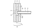
図3は、本実施の形態に係る熱交換器の扁平管10と接続部30との接続構造を示す断面図である。図3では、扁平管10の延伸方向と平行でかつ扁平管10の長径方向と垂直な断面を示している。図1及び図3に示すように、接続部30は、それぞれ扁平管10の延伸方向と垂直に配置された第1板状部材31、第2板状部材32及び第3板状部材33が積層された構成を有している。第1板状部材31、第2板状部材32及び第3板状部材33はいずれも、上下方向に長い長方形平板状の形状を有している。
FIG. 3 is a cross-sectional view showing a connection structure between the
第1板状部材31には、複数の扁平管10の一端が嵌入されて固定される複数の第1貫通孔34が形成されている。複数の第1貫通孔34は、上下方向に並列して設けられている。第1貫通孔34は、扁平管10の外周形状と同様に扁平な開口形状を有しており、扁平管10の傾斜に倣う方向に傾斜している。第1貫通孔34の開口端は、ろう付け等により扁平管10の外周面と全周にわたって接合されている。
The first plate-
第2板状部材32には、複数の第2貫通孔35が形成されている。複数の第2貫通孔35は、上下方向に並列して設けられており、上下方向で互いに仕切られている。第2貫通孔35は、扁平管10の外周形状と同様に扁平な開口形状を有している。第2貫通孔35の開口面積は、第1貫通孔34の開口面積と同一又はそれより大きくなっている。扁平管10の延伸方向と平行に見ると、第2貫通孔35の開口端は、扁平管10の外周面よりも外側に位置している。第2貫通孔35の内部には、接続空間37が形成される。扁平管10の一端は、第1貫通孔34を貫通して第2貫通孔35にまで達している。これにより、扁平管10の一端に位置する先端部10eは、接続空間37に面している。すなわち、扁平管10の一端は、接続空間37に対して直接接続されている。接続空間37は、当該接続空間37に接続された扁平管10の複数の冷媒通路12と連通している。
A plurality of second through
第3板状部材33には、複数の接続空間37とそれぞれ連通する複数の第3貫通孔36が形成されている。複数の第3貫通孔36は、上下方向に並列して設けられている。第3貫通孔36は、例えば円形状の開口形状を有している。第3貫通孔36の開口面積は、第2貫通孔35の開口面積よりも小さくなっている。
The third plate-shaped
冷媒分配器40は、冷媒を分流させる分流器41と、分流器41と複数の接続空間37とを接続する複数のキャピラリチューブ42と、を有している。本実施の形態では、ディストリビュータ方式の冷媒分配器40を例示しているが、冷媒分配器40の形態はこれに限られない。冷媒分配器40は、複数の板状部材が積層された積層型であってもよいし、ヘッダタンクを備えるヘッダ型であってもよい。また、冷媒分配器40と接続部30とは一体的に構成されていてもよい。
The
図4は、図3のIV−IV断面を示す断面図である。図4の上下方向は、鉛直上下方向を表している。図4では、空気の流れ方向を白抜き矢印で示している。図4に示すように、複数の接続空間37は、扁平管10毎に独立して設けられている。複数の接続空間37は、少なくとも上下方向で互いに仕切られている。扁平管10の延伸方向に平行に見ると、複数の接続空間37のそれぞれは、長円形状等の扁平な形状を有している。接続空間37は、平面状の上面37a及び下面37bと、円弧状の第1側面37c及び第2側面37dと、によって画定されている。上面37a、下面37b、第1側面37c及び第2側面37dは、第2貫通孔35の開口端により構成されている。第1側面37cは、接続空間37の風上側に位置しており、扁平管10の第1側端部10aと対面している。第2側面37dは、接続空間37の風下側に位置しており、扁平管10の第2側端部10bと対面している。接続空間37は、第1側面37cの高さ位置が第2側面37dの高さ位置よりも低くなるように傾斜して形成されている。これにより、接続空間37の下面37bは、扁平管10の傾斜に倣う方向に傾斜している。下面37bは、風上側に配置される第1領域37b1と、第1領域37b1よりも風下側に配置される第2領域37b2と、を有する。第1領域37b1の高さ位置は、第2領域37b2の高さ位置よりも低くなっている。すなわち、下面37bは、風上側が風下側よりも重力方向下側に位置するように傾斜している。図4に示す構成では、下面37bの傾斜角度が扁平管10の傾斜角度と一致しているが、下面37bの傾斜角度は扁平管10の傾斜角度と一致していなくてもよい。同様に、接続空間37の上面37aは、扁平管10の傾斜に倣う方向に傾斜している。上面37aは、風上側に配置される第3領域37a1と、第3領域37a1よりも風下側に配置される第4領域37a2と、を有する。第3領域37a1の高さ位置は、第4領域37a2の高さ位置よりも低くなっている。すなわち、上面37aは、風上側が風下側よりも重力方向下側に位置するように傾斜している。図4に示す構成では、上面37aの傾斜角度が扁平管10の傾斜角度と一致しているが、上面37aの傾斜角度は扁平管10の傾斜角度と一致していなくてもよい。
FIG. 4 is a cross-sectional view showing the IV-IV cross section of FIG. The vertical direction in FIG. 4 represents a vertical vertical direction. In FIG. 4, the air flow direction is indicated by a white arrow. As shown in FIG. 4, a plurality of
また、図4に示す構成では、上面37a、第1側面37c及び第2側面37dが扁平管10に沿うように形成されているが、上面37a、第1側面37c及び第2側面37dは、必ずしも扁平管10に沿うように形成されている必要はない。図5は、本実施の形態に係る熱交換器の構成の変形例を示す断面図である。図5では、図4と対応する部分の断面を示している。図5に示すように、接続空間37の上面37aは、扁平管10には沿わずに、水平方向に沿って形成されている。接続空間37の第1側面37c及び第2側面37dは、扁平管10には沿わずに、上下方向に沿って形成されている。第1領域37b1の高さ位置が第2領域37b2の高さ位置よりも低くなるように下面37bが傾斜している点は、図4に示した構成と同様である。
Further, in the configuration shown in FIG. 4, the
本実施の形態に係る熱交換器の動作について説明する。熱交換器が冷凍サイクル装置の蒸発器として機能する場合、冷媒分配器40には外部から気液二相冷媒が流入する。冷媒分配器40に流入した気液二相冷媒は、分流器41によって複数のキャピラリチューブ42に均等に分配される。複数のキャピラリチューブ42のそれぞれに分配された気液二相冷媒は、複数の接続空間37のそれぞれに供給される。
The operation of the heat exchanger according to the present embodiment will be described. When the heat exchanger functions as an evaporator of the refrigeration cycle device, the gas-liquid two-phase refrigerant flows into the
図6は、本実施の形態に係る熱交換器が蒸発器として機能する場合の接続空間37の状態を示す図である。図6では、図4と同一の断面を示している。図6に示すように、接続空間37に流入した気液二相冷媒のうち密度の大きい液冷媒71は、接続空間37内の下部に移動する。気液二相冷媒のうち密度の小さいガス冷媒72は、接続空間37内の上部に移動する。下面37bの傾斜により、液冷媒71は、接続空間37内の第1側面37c寄りに溜まり、ガス冷媒72は、接続空間37内の第2側面37d寄りに溜まる。液冷媒71とガス冷媒72との界面となる液面73は、複数の冷媒通路12の並列方向すなわち扁平管10の長径方向に対して傾斜する。この結果、接続空間37から複数の冷媒通路12のそれぞれには、気液の比率が互いに異なる冷媒が流入する。第1側端部10aに近い冷媒通路12ほど液の比率が高い冷媒が流入し、第1側端部10aに最も近い冷媒通路12には、液単相冷媒又は液の比率が最も高い気液二相冷媒が流入する。一方、第2側端部10bに近い冷媒通路12ほど、ガスの比率が高い冷媒が流入する。
FIG. 6 is a diagram showing a state of the
扁平管10の複数の冷媒通路12に流入した冷媒は、扁平管10の延伸方向に沿って流通する。複数の冷媒通路12を流通する冷媒は、空気との熱交換により蒸発してガス冷媒となり、扁平管10の他端側に設けられたヘッダ集合管に流入する。
The refrigerant that has flowed into the plurality of
ここで、扁平管10の前縁となる風上側の第1側端部10aでは、冷媒と空気との間の熱伝達率が扁平管10で最も高くなる。このため、第1側端部10a寄りの冷媒通路12に液の比率が高い冷媒を流通させることにより、液冷媒を積極的に蒸発させることができる。したがって、本実施の形態によれば、熱交換器の熱交換器性能を向上させることができる。熱交換器性能の向上により冷凍サイクルを効率的に運転することができるため、冷凍サイクル装置の省エネルギー化を実現することができる。
Here, at the first
また、熱交換器の伝熱管として扁平管が用いられる場合には、伝熱管として円管が用いられる場合と比較して冷媒の圧力損失が大きくなる。このため、熱交換器のパス数を多くする必要があることから、扁平管が用いられた熱交換器には、通常、多分岐の冷媒分配器が備えられる。冷媒分配器の分岐数が多くなると、接続空間の数も多くなるため、熱交換器における接続空間の容積の総和が大きくなる。これにより、接続空間に滞留する冷媒量が多くなってしまうため、冷凍サイクル装置の冷媒量が増大してしまう場合がある。これに対し、本実施の形態では、接続空間37の上面37a及び下面37bの双方が扁平管10の傾斜に倣う方向に傾斜している。これにより、接続空間37の上面37a及び下面37bの双方を扁平管10の外周面に沿うように形成でき、接続空間37のそれぞれの容積を小さくすることができるため、熱交換器における接続空間37の容積の総和の増大を抑えることができる。したがって、本実施の形態によれば、冷凍サイクル装置の冷媒量を削減できるという効果も得られる。
Further, when a flat tube is used as the heat transfer tube of the heat exchanger, the pressure loss of the refrigerant becomes larger as compared with the case where the circular tube is used as the heat transfer tube. Therefore, since it is necessary to increase the number of paths of the heat exchanger, the heat exchanger in which the flat tube is used is usually provided with a multi-branch refrigerant distributor. As the number of branches of the refrigerant distributor increases, the number of connection spaces also increases, so that the total volume of the connection spaces in the heat exchanger increases. As a result, the amount of refrigerant staying in the connection space increases, which may increase the amount of refrigerant in the refrigeration cycle apparatus. On the other hand, in the present embodiment, both the
また、本実施の形態の熱交換器が冷凍サイクル装置の蒸発器として機能する場合、扁平管10を流れる冷媒の温度は空気温度よりも低くなる。扁平管10又は伝熱フィンの表面温度が空気の露点温度以下になると、扁平管10又は伝熱フィンの表面で結露が生じる。本実施の形態では、扁平管10が傾斜して設けられているため、扁平管10又は伝熱フィンの表面の結露水は、扁平管10の上面で滞留することなく下方に円滑に流れ落ちる。したがって、本実施の形態によれば、熱交換器から結露水を容易に排水することができるという効果も得られる。
Further, when the heat exchanger of the present embodiment functions as an evaporator of the refrigeration cycle device, the temperature of the refrigerant flowing through the
また、本実施の形態の熱交換器は、冷凍サイクル装置の室外熱交換器として用いることができる。この場合、外気温度が低い状態で熱交換器が蒸発器として機能すると、結露水が霜となって熱交換器に付着する。このため、冷凍サイクル装置では、霜を融解させる除霜運転が定期的に行われる。本実施の形態では、扁平管10が傾斜して設けられているため、除霜運転による霜の融解によって生じたドレン水は、扁平管10の上面で滞留することなく下方に円滑に流れ落ちる。したがって、本実施の形態によれば、除霜運転で生じたドレン水を熱交換器から容易に排水することができるため、除霜時間を短縮できるという効果も得られる。
Further, the heat exchanger of the present embodiment can be used as an outdoor heat exchanger of the refrigeration cycle device. In this case, if the heat exchanger functions as an evaporator when the outside air temperature is low, the condensed water becomes frost and adheres to the heat exchanger. Therefore, in the refrigeration cycle device, a defrosting operation for melting frost is periodically performed. In the present embodiment, since the
以上説明したように、本実施の形態に係る熱交換器は、それぞれ水平方向に延伸して互いに上下方向に並列し、冷媒を流通させる複数の扁平管10と、複数の扁平管10の一端がそれぞれ接続される複数の接続空間37が形成された接続部30と、複数の接続空間37のそれぞれに接続され、複数の接続空間37を介して複数の扁平管10に冷媒を分配する冷媒分配器40と、を備えている。複数の扁平管10のそれぞれは、風上側に配置される第1側端部10aと、風下側に配置される第2側端部10bと、第1側端部10aと第2側端部10bとの間に並列した複数の冷媒通路12と、を有する。また、複数の扁平管10のそれぞれは、第1側端部10aの上下方向における高さ位置が第2側端部10bの上下方向における高さ位置よりも低くなるように傾斜している。複数の接続空間37は、上下方向で互いに仕切られている。複数の接続空間37のそれぞれの下面37bは、風上側に配置される第1領域37b1と、風下側に配置される第2領域37b2と、を有するとともに、第1領域37b1の上下方向における高さ位置が第2領域37b2の上下方向における高さ位置よりも低くなるように傾斜している。
As described above, in the heat exchanger according to the present embodiment, each of the plurality of
この構成によれば、冷媒分配器40によって接続空間37に分配された冷媒は、接続空間37内の風上寄りに溜まる液冷媒71と、接続空間37内の風下寄りに溜まるガス冷媒72とに分離される。このため、冷媒が接続空間37から扁平管10の複数の冷媒通路12に流入する際、第1側端部10aに近い冷媒通路12ほど液の比率が高い冷媒を流入させることができる。これにより、冷媒と空気との間の熱伝達率が高い第1側端部10a寄りの冷媒通路12に液の比率が高い冷媒を流通させることができるため、液冷媒を積極的に蒸発させることができる。したがって、熱交換器の熱交換器性能を向上させることができる。
According to this configuration, the refrigerant distributed to the
また、本実施の形態に係る熱交換器において、複数の接続空間37のそれぞれの上面37aは、風上側に配置される第3領域37a1と、風下側に配置される第4領域37a2と、を有するとともに、第3領域37a1の上下方向における高さ位置が第4領域37a2の上下方向における高さ位置よりも低くなるように傾斜していてもよい。この構成によれば、接続空間37の容積を小さくすることができるため、冷凍サイクル装置の冷媒量を削減することができる。
Further, in the heat exchanger according to the present embodiment, the
また、本実施の形態に係る熱交換器において、接続部30は、複数の板状部材(例えば、第1板状部材31、第2板状部材32及び第3板状部材33)を用いて形成されていてもよい。この構成によれば、複数の接続空間37を有する接続部30を、プレス機などによる打ち抜き加工を用いて成形することができるため、熱交換器の生産性を向上させることができる。
Further, in the heat exchanger according to the present embodiment, the connecting
実施の形態2.
本発明の実施の形態2に係る冷凍サイクル装置について説明する。図7は、本実施の形態に係る冷凍サイクル装置の構成を示す冷媒回路図である。本実施の形態では、冷凍サイクル装置として空気調和装置を例示しているが、本実施の形態の冷凍サイクル装置は、給湯装置などにも適用できる。図7に示すように、冷凍サイクル装置は、圧縮機51、四方弁52、室内熱交換器53、減圧装置54及び室外熱交換器55が冷媒配管を介して環状に接続された冷媒回路50を有している。また、冷凍サイクル装置は、室外機56及び室内機57を有している。室外機56には、圧縮機51、四方弁52、室外熱交換器55及び減圧装置54と、室外熱交換器55に室外空気を供給する室外送風機58と、が収容されている。室内機57には、室内熱交換器53と、室内熱交換器53に空気を供給する室内送風機59と、が収容されている。室外機56と室内機57との間は、冷媒配管の一部である2本の延長配管60、61を介して接続されている。Embodiment 2.
The refrigeration cycle apparatus according to the second embodiment of the present invention will be described. FIG. 7 is a refrigerant circuit diagram showing the configuration of the refrigeration cycle device according to the present embodiment. In the present embodiment, the air conditioner is exemplified as the refrigerating cycle device, but the refrigerating cycle device of the present embodiment can also be applied to a hot water supply device or the like. As shown in FIG. 7, the refrigerating cycle device includes a
圧縮機51は、吸入した冷媒を圧縮して吐出する流体機械である。四方弁52は、不図示の制御装置の制御により、冷房運転時と暖房運転時とで冷媒の流路を切り替える装置である。室内熱交換器53は、内部を流通する冷媒と、室内送風機59により供給される室内空気と、の熱交換を行う熱交換器である。室内熱交換器53は、暖房運転時には凝縮器として機能し、冷房運転時には蒸発器として機能する。減圧装置54は、冷媒を減圧させる装置である。減圧装置54としては、制御装置の制御により開度が調節される電子膨張弁を用いることができる。室外熱交換器55は、内部を流通する冷媒と、室外送風機58により供給される空気と、の熱交換を行う熱交換器である。室外熱交換器55は、暖房運転時には蒸発器として機能し、冷房運転時には凝縮器として機能する。
The
室外熱交換器55及び室内熱交換器53の少なくとも一方には、実施の形態1の熱交換器が用いられている。冷媒分配器40及び接続部30は、熱交換器において液相冷媒がより多くなる位置に配置されるのが望ましい。具体的には、冷媒分配器40及び接続部30は、冷媒回路50での冷媒の流れにおいて、蒸発器として機能する熱交換器の入口側、すなわち凝縮器として機能する熱交換器の出口側に配置されるのが望ましい。
The heat exchanger of the first embodiment is used for at least one of the
図8は、本実施の形態の変形例に係る冷凍サイクル装置の構成を示す冷媒回路図である。図8に示すように、本変形例では、室外熱交換器55は、熱交換部55aと熱交換部55bとに分割されている。熱交換部55a及び熱交換部55bは、冷媒の流れにおいて直列に接続されている。また、室内熱交換器53は、熱交換部53aと熱交換部53bとに分割されている。熱交換部53a及び熱交換部53bは、冷媒の流れにおいて直列に接続されている。
FIG. 8 is a refrigerant circuit diagram showing a configuration of a refrigeration cycle device according to a modified example of the present embodiment. As shown in FIG. 8, in this modification, the
本変形例においても、冷媒分配器40及び接続部30は、熱交換器において液相冷媒がより多くなる位置に配置されるのが望ましい。具体的には、冷媒分配器40及び接続部30は、冷媒回路50での冷媒の流れにおいて、蒸発器として機能する熱交換部55a、55b、53a、53bのそれぞれの入口側に配置されるのが望ましい。言い換えれば、冷媒分配器40及び接続部30は、冷媒回路50での冷媒の流れにおいて、凝縮器として機能する熱交換部55a、55b、53a、53bのそれぞれの出口側に配置されるのが望ましい。
Also in this modification, it is desirable that the
以上説明したように、本実施の形態に係る冷凍サイクル装置は、実施の形態1に係る熱交換器を備えたものである。冷媒分配器40及び接続部30は、蒸発器として機能する熱交換器の入口側に配置されるのが望ましい。この構成によれば、冷凍サイクル装置において、実施の形態1と同様の効果が得られる。
As described above, the refrigeration cycle apparatus according to the present embodiment includes the heat exchanger according to the first embodiment. It is desirable that the
上記の各実施の形態は、互いに組み合わせて実施することが可能である。 Each of the above embodiments can be implemented in combination with each other.
本願明細書中の「水平方向」には、完全に水平な方向だけでなく、技術常識を考慮して実質的に水平とみなすことができる略水平な方向も含まれる。 The "horizontal direction" in the present specification includes not only a completely horizontal direction but also a substantially horizontal direction which can be regarded as substantially horizontal in consideration of common general technical knowledge.
10 扁平管、10a 第1側端部、10b 第2側端部、10c、10d 平坦面、10e 先端部、11 隙間、12 冷媒通路、30 接続部、31 第1板状部材、32 第2板状部材、33 第3板状部材、34 第1貫通孔、35 第2貫通孔、36 第3貫通孔、37 接続空間、37a 上面、37a1 第3領域、37a2 第4領域、37b 下面、37b1 第1領域、37b2 第2領域、37c 第1側面、37d 第2側面、40 冷媒分配器、41 分流器、42 キャピラリチューブ、50 冷媒回路、51 圧縮機、52 四方弁、53 室内熱交換器、53a、53b 熱交換部、54 減圧装置、55 室外熱交換器、55a、55b 熱交換部、56 室外機、57 室内機、58 室外送風機、59 室内送風機、60、61 延長配管、71 液冷媒、72 ガス冷媒、73 液面。 10 Flat tube, 10a 1st side end, 10b 2nd side end, 10c, 10d flat surface, 10e tip, 11 gap, 12 refrigerant passage, 30 connection, 31 1st plate-like member, 32 2nd plate Shaped member, 33 3rd plate-shaped member, 34 1st through hole, 35 2nd through hole, 36 3rd through hole, 37 connection space, 37a upper surface, 37a1 3rd region, 37a2 4th region, 37b lower surface, 37b1 first 1 region, 37b2 2nd region, 37c 1st side, 37d 2nd side, 40 refrigerant distributor, 41 diverter, 42 capillary tube, 50 refrigerant circuit, 51 compressor, 52 four-way valve, 53 indoor heat exchanger, 53a , 53b heat exchanger, 54 decompressor, 55 outdoor heat exchanger, 55a, 55b heat exchanger, 56 outdoor unit, 57 indoor unit, 58 outdoor blower, 59 indoor blower, 60, 61 extension pipe, 71 liquid refrigerant, 72 Gas refrigerant, 73 liquid level.
Claims (3)
それぞれ水平方向に延伸して互いに上下方向に並列し、冷媒を流通させる複数の扁平管と、
前記複数の扁平管の一端がそれぞれ接続される複数の接続空間が形成された接続部と、
前記複数の接続空間のそれぞれに接続された冷媒分配器と、
を備え、
前記複数の扁平管のそれぞれは、風上側に配置される第1側端部と、風下側に配置される第2側端部と、前記第1側端部と前記第2側端部との間に並列した複数の冷媒通路と、を有するとともに、前記第1側端部の前記上下方向における高さ位置が前記第2側端部の前記上下方向における高さ位置よりも低くなるように傾斜しており、
前記複数の接続空間は、前記上下方向で互いに仕切られており、
前記複数の接続空間のそれぞれの下面は、風上側に配置される第1領域と、風下側に配置される第2領域と、を有するとともに、前記第1領域の前記上下方向における高さ位置が前記第2領域の前記上下方向における高さ位置よりも低くなるように傾斜し、
前記複数の接続空間のそれぞれの上面は、前記複数の扁平管のそれぞれには沿わずに、水平方向に沿って形成されている熱交換器。 A heat exchanger that functions as an evaporator for refrigeration cycle equipment.
Multiple flat pipes that extend horizontally and are parallel to each other in the vertical direction to allow the refrigerant to flow.
A connection portion in which a plurality of connection spaces are formed in which one ends of the plurality of flat tubes are connected to each other.
A refrigerant distributor connected to each of the plurality of connection spaces,
Equipped with
Each of the plurality of flat tubes has a first side end portion arranged on the leeward side, a second side end portion arranged on the leeward side, and the first side end portion and the second side end portion. It has a plurality of refrigerant passages arranged in parallel between them, and is inclined so that the height position of the first side end portion in the vertical direction is lower than the height position of the second side end portion in the vertical direction. And
The plurality of connection spaces are partitioned from each other in the vertical direction.
The lower surface of each of the plurality of connection spaces has a first region arranged on the leeward side and a second region arranged on the leeward side, and the height position of the first region in the vertical direction is set. The second region is tilted so as to be lower than the height position in the vertical direction .
A heat exchanger in which the upper surface of each of the plurality of connection spaces is formed along the horizontal direction, not along each of the plurality of flat tubes.
Applications Claiming Priority (1)
| Application Number | Priority Date | Filing Date | Title |
|---|---|---|---|
| PCT/JP2018/017427 WO2019211893A1 (en) | 2018-05-01 | 2018-05-01 | Heat exchanger and refrigeration cycle device |
Publications (2)
| Publication Number | Publication Date |
|---|---|
| JPWO2019211893A1 JPWO2019211893A1 (en) | 2021-02-18 |
| JP6987227B2 true JP6987227B2 (en) | 2021-12-22 |
Family
ID=68386421
Family Applications (1)
| Application Number | Title | Priority Date | Filing Date |
|---|---|---|---|
| JP2020516986A Active JP6987227B2 (en) | 2018-05-01 | 2018-05-01 | Heat exchanger and refrigeration cycle equipment |
Country Status (6)
| Country | Link |
|---|---|
| US (1) | US11629896B2 (en) |
| EP (1) | EP3789697B1 (en) |
| JP (1) | JP6987227B2 (en) |
| CN (1) | CN111902683B (en) |
| ES (1) | ES2977450T3 (en) |
| WO (1) | WO2019211893A1 (en) |
Families Citing this family (2)
| Publication number | Priority date | Publication date | Assignee | Title |
|---|---|---|---|---|
| US11536496B2 (en) * | 2018-10-29 | 2022-12-27 | Mitsubishi Electric Corporation | Heat exchanger and refrigeration cycle apparatus |
| JPWO2022145003A1 (en) * | 2020-12-28 | 2022-07-07 |
Family Cites Families (17)
| Publication number | Priority date | Publication date | Assignee | Title |
|---|---|---|---|---|
| JPH0791873A (en) * | 1993-09-20 | 1995-04-07 | Hitachi Ltd | Fin and tube type heat exchanger |
| JPH09257386A (en) * | 1996-03-22 | 1997-10-03 | Sanden Corp | Distributor and heat exchanger equipped with it |
| JP3763624B2 (en) * | 1996-12-06 | 2006-04-05 | 昭和電工株式会社 | Heat exchange device for refrigerant condensation, heat exchange device for refrigerant evaporation, automotive and household air conditioners |
| US6302197B1 (en) * | 1999-12-22 | 2001-10-16 | Isteon Global Technologies, Inc. | Louvered plastic heat exchanger |
| US7650935B2 (en) * | 2001-12-21 | 2010-01-26 | Behr Gmbh & Co. Kg | Heat exchanger, particularly for a motor vehicle |
| JP2004069228A (en) * | 2002-08-08 | 2004-03-04 | Denso Corp | Heat exchanger |
| EP1548387A1 (en) * | 2002-09-10 | 2005-06-29 | Gac Corporation | Heat exchanger and method of producing the same |
| US20110120177A1 (en) * | 2007-12-18 | 2011-05-26 | Kirkwood Allen C | Heat exchanger for shedding water |
| JP4983998B2 (en) * | 2010-09-29 | 2012-07-25 | ダイキン工業株式会社 | Heat exchanger |
| EP3021067B1 (en) * | 2013-07-08 | 2018-08-22 | Mitsubishi Electric Corporation | Laminated header, heat exchanger, air conditioning device, and method for connecting plate-shaped body and pipe of laminated header |
| JP2015055413A (en) | 2013-09-11 | 2015-03-23 | ダイキン工業株式会社 | Heat exchanger |
| US10288363B2 (en) * | 2013-09-26 | 2019-05-14 | Mitsubishi Electric Corporation | Laminated header, heat exchanger, and air-conditioning apparatus |
| JP6180338B2 (en) * | 2014-01-29 | 2017-08-16 | ジョンソンコントロールズ ヒタチ エア コンディショニング テクノロジー(ホンコン)リミテッド | Air conditioner |
| EP3136039B1 (en) | 2014-04-21 | 2019-11-27 | Mitsubishi Electric Corporation | Laminated header, heat exchanger, and air-conditioner |
| JP6333401B2 (en) * | 2014-10-07 | 2018-05-30 | 三菱電機株式会社 | Heat exchanger and air conditioner |
| JP6070685B2 (en) | 2014-12-26 | 2017-02-01 | ダイキン工業株式会社 | Heat exchanger and air conditioner |
| GB2562935B (en) * | 2016-04-07 | 2021-02-17 | Mitsubishi Electric Corp | Distributer, heat exchanger, and air-conditioning apparatus |
-
2018
- 2018-05-01 US US16/980,465 patent/US11629896B2/en active Active
- 2018-05-01 JP JP2020516986A patent/JP6987227B2/en active Active
- 2018-05-01 ES ES18917178T patent/ES2977450T3/en active Active
- 2018-05-01 WO PCT/JP2018/017427 patent/WO2019211893A1/en unknown
- 2018-05-01 CN CN201880091794.3A patent/CN111902683B/en active Active
- 2018-05-01 EP EP18917178.8A patent/EP3789697B1/en active Active
Also Published As
| Publication number | Publication date |
|---|---|
| US11629896B2 (en) | 2023-04-18 |
| ES2977450T3 (en) | 2024-08-23 |
| WO2019211893A1 (en) | 2019-11-07 |
| US20210018233A1 (en) | 2021-01-21 |
| EP3789697A1 (en) | 2021-03-10 |
| EP3789697B1 (en) | 2024-03-13 |
| CN111902683B (en) | 2022-05-10 |
| JPWO2019211893A1 (en) | 2021-02-18 |
| EP3789697A4 (en) | 2021-03-31 |
| CN111902683A (en) | 2020-11-06 |
Similar Documents
| Publication | Publication Date | Title |
|---|---|---|
| US11009300B2 (en) | Heat exchanger and air-conditioning apparatus | |
| JP5195733B2 (en) | Heat exchanger and refrigeration cycle apparatus equipped with the same | |
| EP3156752B1 (en) | Heat exchanger | |
| US10041710B2 (en) | Heat exchanger and air conditioner | |
| JP6890509B2 (en) | Air conditioner | |
| JP2006284133A (en) | Heat exchanger | |
| WO2019004139A1 (en) | Heat exchanger | |
| JP6987227B2 (en) | Heat exchanger and refrigeration cycle equipment | |
| WO2018235215A1 (en) | Heat exchanger, refrigeration cycle device, and air conditioner | |
| WO2022264348A1 (en) | Heat exchanger and refrigeration cycle device | |
| US11384996B2 (en) | Heat exchanger and refrigeration cycle apparatus | |
| JP6104378B2 (en) | Air conditioner | |
| US11573056B2 (en) | Heat exchanger, heat exchanger unit, and refrigeration cycle apparatus | |
| JP7118279B2 (en) | HEAT EXCHANGER, MANUFACTURING METHOD THEREOF, AND AIR CONDITIONER | |
| JP6599056B1 (en) | Gas header, heat exchanger and refrigeration cycle apparatus | |
| JP2014137172A (en) | Heat exchanger and refrigerator | |
| JP2012067971A (en) | Heat exchanger and apparatus | |
| WO2023281656A1 (en) | Heat exchanger and refrigeration cycle device | |
| JPWO2019155571A1 (en) | Heat exchanger and refrigeration cycle equipment | |
| WO2021234957A1 (en) | Heat exchanger and air conditioner comprising said heat exchanger | |
| US20240271837A1 (en) | Refrigeration cycle apparatus | |
| JP6928793B2 (en) | Plate fin laminated heat exchanger and freezing system using it | |
| JP7080395B2 (en) | Heat exchanger unit and refrigeration cycle device | |
| WO2022215193A1 (en) | Refrigeration cycle device | |
| WO2023188421A1 (en) | Outdoor unit and air conditioner equipped with same |
Legal Events
| Date | Code | Title | Description |
|---|---|---|---|
| A521 | Request for written amendment filed |
Free format text: JAPANESE INTERMEDIATE CODE: A523 Effective date: 20200907 |
|
| A621 | Written request for application examination |
Free format text: JAPANESE INTERMEDIATE CODE: A621 Effective date: 20200907 |
|
| A131 | Notification of reasons for refusal |
Free format text: JAPANESE INTERMEDIATE CODE: A131 Effective date: 20210525 |
|
| A521 | Request for written amendment filed |
Free format text: JAPANESE INTERMEDIATE CODE: A523 Effective date: 20210720 |
|
| TRDD | Decision of grant or rejection written | ||
| A01 | Written decision to grant a patent or to grant a registration (utility model) |
Free format text: JAPANESE INTERMEDIATE CODE: A01 Effective date: 20211102 |
|
| A61 | First payment of annual fees (during grant procedure) |
Free format text: JAPANESE INTERMEDIATE CODE: A61 Effective date: 20211130 |
|
| R150 | Certificate of patent or registration of utility model |
Ref document number: 6987227 Country of ref document: JP Free format text: JAPANESE INTERMEDIATE CODE: R150 |