WO2023281656A1 - Heat exchanger and refrigeration cycle device - Google Patents
Heat exchanger and refrigeration cycle device Download PDFInfo
- Publication number
- WO2023281656A1 WO2023281656A1 PCT/JP2021/025606 JP2021025606W WO2023281656A1 WO 2023281656 A1 WO2023281656 A1 WO 2023281656A1 JP 2021025606 W JP2021025606 W JP 2021025606W WO 2023281656 A1 WO2023281656 A1 WO 2023281656A1
- Authority
- WO
- WIPO (PCT)
- Prior art keywords
- heat transfer
- heat exchanger
- heat
- refrigerant
- flow
- Prior art date
Links
- 238000005057 refrigeration Methods 0.000 title description 14
- 239000003507 refrigerant Substances 0.000 claims abstract description 116
- 239000000203 mixture Substances 0.000 claims abstract description 33
- 239000007788 liquid Substances 0.000 description 17
- 230000004048 modification Effects 0.000 description 15
- 238000012986 modification Methods 0.000 description 15
- 238000010438 heat treatment Methods 0.000 description 13
- 238000001816 cooling Methods 0.000 description 11
- 238000010586 diagram Methods 0.000 description 7
- 230000000694 effects Effects 0.000 description 6
- 239000002826 coolant Substances 0.000 description 5
- XAGFODPZIPBFFR-UHFFFAOYSA-N aluminium Chemical compound [Al] XAGFODPZIPBFFR-UHFFFAOYSA-N 0.000 description 4
- 229910052782 aluminium Inorganic materials 0.000 description 4
- 239000000463 material Substances 0.000 description 4
- RYGMFSIKBFXOCR-UHFFFAOYSA-N Copper Chemical compound [Cu] RYGMFSIKBFXOCR-UHFFFAOYSA-N 0.000 description 2
- 241001274961 Rubus repens Species 0.000 description 2
- 229910052802 copper Inorganic materials 0.000 description 2
- 239000010949 copper Substances 0.000 description 2
- 230000007423 decrease Effects 0.000 description 2
- 239000007787 solid Substances 0.000 description 2
- 238000006073 displacement reaction Methods 0.000 description 1
- 239000007921 spray Substances 0.000 description 1
- 230000005514 two-phase flow Effects 0.000 description 1
Images


Classifications
-
- F—MECHANICAL ENGINEERING; LIGHTING; HEATING; WEAPONS; BLASTING
- F28—HEAT EXCHANGE IN GENERAL
- F28D—HEAT-EXCHANGE APPARATUS, NOT PROVIDED FOR IN ANOTHER SUBCLASS, IN WHICH THE HEAT-EXCHANGE MEDIA DO NOT COME INTO DIRECT CONTACT
- F28D1/00—Heat-exchange apparatus having stationary conduit assemblies for one heat-exchange medium only, the media being in contact with different sides of the conduit wall, in which the other heat-exchange medium is a large body of fluid, e.g. domestic or motor car radiators
- F28D1/02—Heat-exchange apparatus having stationary conduit assemblies for one heat-exchange medium only, the media being in contact with different sides of the conduit wall, in which the other heat-exchange medium is a large body of fluid, e.g. domestic or motor car radiators with heat-exchange conduits immersed in the body of fluid
- F28D1/04—Heat-exchange apparatus having stationary conduit assemblies for one heat-exchange medium only, the media being in contact with different sides of the conduit wall, in which the other heat-exchange medium is a large body of fluid, e.g. domestic or motor car radiators with heat-exchange conduits immersed in the body of fluid with tubular conduits
- F28D1/047—Heat-exchange apparatus having stationary conduit assemblies for one heat-exchange medium only, the media being in contact with different sides of the conduit wall, in which the other heat-exchange medium is a large body of fluid, e.g. domestic or motor car radiators with heat-exchange conduits immersed in the body of fluid with tubular conduits the conduits being bent, e.g. in a serpentine or zig-zag
- F28D1/0477—Heat-exchange apparatus having stationary conduit assemblies for one heat-exchange medium only, the media being in contact with different sides of the conduit wall, in which the other heat-exchange medium is a large body of fluid, e.g. domestic or motor car radiators with heat-exchange conduits immersed in the body of fluid with tubular conduits the conduits being bent, e.g. in a serpentine or zig-zag the conduits being bent in a serpentine or zig-zag
- F28D1/0478—Heat-exchange apparatus having stationary conduit assemblies for one heat-exchange medium only, the media being in contact with different sides of the conduit wall, in which the other heat-exchange medium is a large body of fluid, e.g. domestic or motor car radiators with heat-exchange conduits immersed in the body of fluid with tubular conduits the conduits being bent, e.g. in a serpentine or zig-zag the conduits being bent in a serpentine or zig-zag the conduits having a non-circular cross-section
-
- F—MECHANICAL ENGINEERING; LIGHTING; HEATING; WEAPONS; BLASTING
- F25—REFRIGERATION OR COOLING; COMBINED HEATING AND REFRIGERATION SYSTEMS; HEAT PUMP SYSTEMS; MANUFACTURE OR STORAGE OF ICE; LIQUEFACTION SOLIDIFICATION OF GASES
- F25B—REFRIGERATION MACHINES, PLANTS OR SYSTEMS; COMBINED HEATING AND REFRIGERATION SYSTEMS; HEAT PUMP SYSTEMS
- F25B39/00—Evaporators; Condensers
-
- F—MECHANICAL ENGINEERING; LIGHTING; HEATING; WEAPONS; BLASTING
- F28—HEAT EXCHANGE IN GENERAL
- F28D—HEAT-EXCHANGE APPARATUS, NOT PROVIDED FOR IN ANOTHER SUBCLASS, IN WHICH THE HEAT-EXCHANGE MEDIA DO NOT COME INTO DIRECT CONTACT
- F28D1/00—Heat-exchange apparatus having stationary conduit assemblies for one heat-exchange medium only, the media being in contact with different sides of the conduit wall, in which the other heat-exchange medium is a large body of fluid, e.g. domestic or motor car radiators
- F28D1/02—Heat-exchange apparatus having stationary conduit assemblies for one heat-exchange medium only, the media being in contact with different sides of the conduit wall, in which the other heat-exchange medium is a large body of fluid, e.g. domestic or motor car radiators with heat-exchange conduits immersed in the body of fluid
- F28D1/04—Heat-exchange apparatus having stationary conduit assemblies for one heat-exchange medium only, the media being in contact with different sides of the conduit wall, in which the other heat-exchange medium is a large body of fluid, e.g. domestic or motor car radiators with heat-exchange conduits immersed in the body of fluid with tubular conduits
- F28D1/053—Heat-exchange apparatus having stationary conduit assemblies for one heat-exchange medium only, the media being in contact with different sides of the conduit wall, in which the other heat-exchange medium is a large body of fluid, e.g. domestic or motor car radiators with heat-exchange conduits immersed in the body of fluid with tubular conduits the conduits being straight
- F28D1/0535—Heat-exchange apparatus having stationary conduit assemblies for one heat-exchange medium only, the media being in contact with different sides of the conduit wall, in which the other heat-exchange medium is a large body of fluid, e.g. domestic or motor car radiators with heat-exchange conduits immersed in the body of fluid with tubular conduits the conduits being straight the conduits having a non-circular cross-section
- F28D1/05366—Assemblies of conduits connected to common headers, e.g. core type radiators
- F28D1/05391—Assemblies of conduits connected to common headers, e.g. core type radiators with multiple rows of conduits or with multi-channel conduits combined with a particular flow pattern, e.g. multi-row multi-stage radiators
-
- F—MECHANICAL ENGINEERING; LIGHTING; HEATING; WEAPONS; BLASTING
- F28—HEAT EXCHANGE IN GENERAL
- F28F—DETAILS OF HEAT-EXCHANGE AND HEAT-TRANSFER APPARATUS, OF GENERAL APPLICATION
- F28F9/00—Casings; Header boxes; Auxiliary supports for elements; Auxiliary members within casings
- F28F9/02—Header boxes; End plates
- F28F9/026—Header boxes; End plates with static flow control means, e.g. with means for uniformly distributing heat exchange media into conduits
- F28F9/027—Header boxes; End plates with static flow control means, e.g. with means for uniformly distributing heat exchange media into conduits in the form of distribution pipes
- F28F9/0275—Header boxes; End plates with static flow control means, e.g. with means for uniformly distributing heat exchange media into conduits in the form of distribution pipes with multiple branch pipes
-
- F—MECHANICAL ENGINEERING; LIGHTING; HEATING; WEAPONS; BLASTING
- F28—HEAT EXCHANGE IN GENERAL
- F28F—DETAILS OF HEAT-EXCHANGE AND HEAT-TRANSFER APPARATUS, OF GENERAL APPLICATION
- F28F1/00—Tubular elements; Assemblies of tubular elements
- F28F1/10—Tubular elements and assemblies thereof with means for increasing heat-transfer area, e.g. with fins, with projections, with recesses
- F28F1/12—Tubular elements and assemblies thereof with means for increasing heat-transfer area, e.g. with fins, with projections, with recesses the means being only outside the tubular element
- F28F1/126—Tubular elements and assemblies thereof with means for increasing heat-transfer area, e.g. with fins, with projections, with recesses the means being only outside the tubular element consisting of zig-zag shaped fins
-
- F—MECHANICAL ENGINEERING; LIGHTING; HEATING; WEAPONS; BLASTING
- F28—HEAT EXCHANGE IN GENERAL
- F28F—DETAILS OF HEAT-EXCHANGE AND HEAT-TRANSFER APPARATUS, OF GENERAL APPLICATION
- F28F1/00—Tubular elements; Assemblies of tubular elements
- F28F1/10—Tubular elements and assemblies thereof with means for increasing heat-transfer area, e.g. with fins, with projections, with recesses
- F28F1/12—Tubular elements and assemblies thereof with means for increasing heat-transfer area, e.g. with fins, with projections, with recesses the means being only outside the tubular element
- F28F1/24—Tubular elements and assemblies thereof with means for increasing heat-transfer area, e.g. with fins, with projections, with recesses the means being only outside the tubular element and extending transversely
- F28F1/32—Tubular elements and assemblies thereof with means for increasing heat-transfer area, e.g. with fins, with projections, with recesses the means being only outside the tubular element and extending transversely the means having portions engaging further tubular elements
Definitions
- the present disclosure relates to heat exchangers and refrigeration cycle devices.
- multi-row heat transfer tubes As a means of improving the performance of heat exchangers in refrigeration cycle equipment, multi-row heat transfer tubes have been proposed. Since heat exchangers are mounted in a limited space, multi-row heat transfer tubes can improve the mounting density of the heat transfer tubes and expand the heat transfer area.
- a heat exchanger of an indoor unit of an air conditioner disclosed in Japanese Patent Application Laid-Open No. 2014-40983 Patent Document 1 has heat transfer tubes arranged in multiple rows.
- heat exchange loss occurs when the refrigerant flows parallel to the air flow due to the effect of temperature distribution in the non-azeotropic refrigerant mixture. occurs.
- the direction of the refrigerant flowing through the heat exchanger is opposite between when the heat exchanger functions as a condenser and when the heat exchanger functions as an evaporator. Therefore, the refrigerant flows parallel to the air flow in either the condenser or the evaporator. Therefore, heat exchange efficiency is reduced in either the condenser or the evaporator.
- the present disclosure has been made in view of the above problems, and an object of the present disclosure is to provide a heat exchanger and a refrigeration cycle that can ensure average heat exchange efficiency in a condenser and an evaporator while using a non-azeotropic refrigerant mixture. to provide the equipment.
- a heat exchanger of the present disclosure includes a first heat transfer section having a plurality of first heat transfer tubes, and a non-azeotropic refrigerant mixture flowing through the plurality of first heat transfer tubes of the first heat transfer section.
- the plurality of first heat transfer tubes are arranged in a row.
- the first heat transfer section includes a plurality of first heat transfer tubes arranged such that the flow of the non-azeotropic refrigerant mixture flowing through the plurality of first heat transfer tubes is orthogonal to the flow of air flowing through the first heat transfer section. have.
- the heat exchanger of the present disclosure it is possible to ensure average heat exchange efficiency in the condenser and evaporator while using a non-azeotropic refrigerant mixture.
- FIG. 1 is a refrigerant circuit diagram of a refrigeration cycle device according to Embodiment 1.
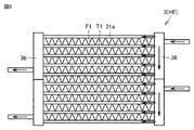
- FIG. 3 is a diagram showing a heat exchanger and a blowout temperature distribution according to Embodiment 1; 1 is a perspective view schematically showing a heat exchanger according to Embodiment 1;
- FIG. 3 is a cross-sectional view schematically showing first heat transfer tubes and second heat transfer tubes of the heat exchanger according to Embodiment 1.
- FIG. 4 is a perspective view schematically showing a capillary tube of the heat exchanger according to Embodiment 1;
- FIG. FIG. 4 is a cross-sectional view schematically showing a modification of the first heat transfer tube and the second heat transfer tube of the heat exchanger according to Embodiment 1;
- FIG. 4 is a cross-sectional view schematically showing Modification 1 of the heat exchanger according to Embodiment 1;
- FIG. 7 is a front view schematically showing Modification 2 of the heat exchanger according to Embodiment 1;
- FIG. 3 shows counter-flow, co-flow and cross-flow heat exchange efficiencies in a condenser and an evaporator.
- 4 is a diagram showing the relationship between refrigerant flow and refrigerant temperature in the condenser and evaporator of the heat exchanger according to Embodiment 1.
- FIG. FIG. 7 is a diagram showing a heat exchanger and a blowout temperature distribution according to Embodiment 2;
- FIG. 7 is a cross-sectional view schematically showing a modification of the heat exchanger according to Embodiment 2;
- FIG. 9 is a diagram showing the relationship between refrigerant flow and refrigerant temperature in a condenser and an evaporator of a heat exchanger according to Embodiment 2;
- FIG. 10 is a diagram showing a heat exchanger and outlet temperature distribution according to Embodiment 3;
- FIG. 10 is a cross-sectional view schematically showing Modification 1 of the heat exchanger according to Embodiment 3;
- FIG. 11 is a cross-sectional view schematically showing Modification 2 of the heat exchanger according to Embodiment 3;
- FIG. 10 is a diagram showing the relationship between refrigerant flow and temperature in a condenser and an evaporator of a heat exchanger according to Embodiment 3;
- Embodiment 1 A configuration of a refrigeration cycle apparatus 100 according to Embodiment 1 will be described with reference to FIG. In Embodiment 1, an air conditioner will be described as an example of the refrigeration cycle device 100.
- FIG. Solid arrows in FIG. 1 indicate the flow of the refrigerant during the cooling operation.
- Broken line arrows in FIG. 1 indicate the flow of the refrigerant during the heating operation.
- the refrigeration cycle device 100 includes a compressor 1, a four-way valve 2, an outdoor heat exchanger 3, an expansion valve 4, an indoor heat exchanger 5, an outdoor fan 6, and an indoor fan. 7 and a control device 8 .
- the heat exchanger HE according to Embodiment 1 is applied to the outdoor heat exchanger 3 .
- a refrigerating cycle device 100 includes an outdoor unit 101 and an indoor unit 102 connected to the outdoor unit 101 .
- a refrigerant circuit 10 includes a compressor 1 , a four-way valve 2 , an outdoor heat exchanger 3 , an expansion valve 4 and an indoor heat exchanger 5 .
- Compressor 1 , four-way valve 2 , outdoor heat exchanger 3 , expansion valve 4 and indoor heat exchanger 5 are connected by piping 20 .
- the refrigerant circuit 10 is configured to circulate the refrigerant.
- the refrigerant is a non-azeotropic mixed refrigerant.
- the non-azeotropic refrigerant mixture contains R32 and may contain R1234yf as another refrigerant.
- the non-azeotropic refrigerant mixture may contain R1123 or R1234ze as another refrigerant.
- the non-azeotropic mixed refrigerant may be a mixed refrigerant of three or more types.
- the compressor 1, the four-way valve 2, the outdoor heat exchanger 3, the expansion valve 4, the outdoor fan 6 and the control device 8 are housed in the outdoor unit 101.
- Indoor heat exchanger 5 and indoor fan 7 are housed in indoor unit 102 .
- the outdoor unit 101 and the indoor unit 102 are connected by a gas pipe 21 and a liquid pipe 22 .
- a part of the pipe 20 constitutes a gas pipe 21 and a liquid pipe 22 .
- the refrigerant circuit 10 is configured such that the refrigerant circulates through the compressor 1, the four-way valve 2, the outdoor heat exchanger 3, the expansion valve 4, the indoor heat exchanger 5, and the four-way valve 2 in this order during cooling operation. Further, the refrigerant circuit 10 is configured such that the refrigerant circulates in the order of the compressor 1, the four-way valve 2, the indoor heat exchanger 5, the expansion valve 4, the outdoor heat exchanger 3, and the four-way valve 2 during the heating operation. .
- the compressor 1 is configured to compress refrigerant.
- the compressor 1 is for compressing the non-azeotropic refrigerant mixture flowing into the heat exchanger HE.
- the compressor 1 is configured to compress and discharge the sucked refrigerant.
- the compressor 1 may be configured to have a variable capacity.
- the compressor 1 may be configured such that the displacement is changed by adjusting the rotational speed of the compressor 1 based on an instruction from the control device 8 .
- the four-way valve 2 is configured to switch the flow of refrigerant so that the refrigerant compressed by the compressor 1 flows to the outdoor heat exchanger 3 or the indoor heat exchanger 5 .
- the four-way valve 2 has a first port P1 to a fourth port P4.
- the first port P1 is connected to the discharge side of the compressor 1 .
- a second port P2 is connected to the suction side of the compressor 1 .
- the third port P3 is connected to the outdoor heat exchanger 3.
- a fourth port P4 is connected to the indoor heat exchanger 5 .
- the four-way valve 2 is configured to flow the refrigerant discharged from the compressor 1 to the outdoor heat exchanger 3 during cooling operation.
- the four-way valve 2 During cooling operation, the four-way valve 2 has the first port P1 connected to the third port P3 and the second port P2 connected to the fourth port P4.
- the four-way valve 2 is configured to flow the refrigerant discharged from the compressor 1 to the indoor heat exchanger 5 during heating operation.
- the four-way valve 2 has the first port P1 connected to the fourth port P4 and the second port P2 connected to the third port P3.
- the outdoor heat exchanger 3 is configured to exchange heat between the refrigerant flowing inside the outdoor heat exchanger 3 and the air flowing outside the outdoor heat exchanger 3 .
- the outdoor heat exchanger 3 is configured to function as a condenser that condenses refrigerant during cooling operation, and to function as an evaporator that evaporates refrigerant during heating operation.
- the expansion valve 4 is configured to reduce the pressure by expanding the refrigerant condensed in the condenser.
- the expansion valve 4 is configured to reduce the pressure of the refrigerant condensed by the outdoor heat exchanger 3 during cooling operation, and to reduce the pressure of the refrigerant condensed by the indoor heat exchanger 5 during heating operation.
- Expansion valve 4 is, for example, an electromagnetic expansion valve.
- the indoor heat exchanger 5 is configured to exchange heat between the refrigerant flowing inside the indoor heat exchanger 5 and the air flowing outside the indoor heat exchanger 5 .
- the indoor heat exchanger 5 is configured to function as an evaporator that evaporates the refrigerant during cooling operation and as a condenser that condenses the refrigerant during heating operation.
- the outdoor blower 6 is configured to blow outdoor air to the outdoor heat exchanger 3. That is, the outdoor fan 6 is configured to supply air to the outdoor heat exchanger 3 .
- the indoor blower 7 is configured to blow indoor air to the indoor heat exchanger 5 . That is, the indoor fan 7 is configured to supply air to the indoor heat exchanger 5 .
- the control device 8 is configured to perform calculations, instructions, etc. to control each device of the refrigeration cycle device 100 .
- the control device 8 is electrically connected to the compressor 1, the four-way valve 2, the expansion valve 4, the outdoor blower 6, the indoor blower 7, etc., and is configured to control these operations.
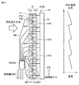
- FIG. 2 shows the relationship between the structure of the heat exchanger HE and the air outlet temperature distribution. Solid arrows in FIG. 3 indicate the flow of refrigerant, and white arrows in FIG. 3 indicate the flow of air.
- the outdoor heat exchanger 3 includes a heat exchange section 31, a header distributor 32, a gas-liquid two-phase distributor 33, and a non-azeotropic refrigerant. have.
- the heat exchange section 31 includes a first heat exchange section 31a and a second heat exchange section 31b.
- the first heat exchange section 31a is arranged on the windward side in the air flow direction D1.
- the first heat exchange portions 31a are arranged in the first row in the air flow direction D1.
- the second heat exchange portion 31b is arranged on the leeward side in the air flow direction D1.
- the second heat exchange portions 31b are arranged in the second row in the air flow direction D1.
- the first heat exchange section 31a includes a first heat transfer section HP1.
- the first heat exchange section 31a includes a plurality of first heat transfer sections HP1.
- the second heat exchange section 31b includes a second heat transfer section HP2.
- the second heat exchange section 31b includes a plurality of second heat transfer sections HP2.
- the first heat exchange portion 31a has a plurality of first fins F1, a plurality of first heat transfer tubes T1, and a plurality of first connection portions C1.
- Each of the plurality of first fins F1 has a plate shape.
- the plurality of first fins F1 are arranged so as to overlap each other.
- the material of the plurality of first fins F1 is, for example, aluminum.
- the multiple first heat transfer tubes T1 penetrate through the multiple first fins F1.
- the plurality of first heat transfer tubes T1 are configured to linearly extend in an orthogonal direction D2 orthogonal to the air flow direction D1.
- the plurality of first connection portions C1 are portions that connect the first heat transfer tubes T1 to each other outside the plurality of first fins F1.
- Each of the plurality of first heat transfer tubes T1 is connected by each of the plurality of first connection portions C1, so that the plurality of first heat transfer tubes T1 and the plurality of first connection portions C1 meander as a whole.
- the material of the plurality of first heat transfer tubes T1 and the plurality of first connection portions C1 is, for example, copper or aluminum.
- the first heat transfer part HP1 has a plurality of first heat transfer tubes T1.
- the plurality of first heat transfer tubes T1 are arranged in a row.
- the plurality of first heat transfer tubes T1 are arranged side by side in a stage direction D3 that intersects the air flow direction D1 and the orthogonal direction D2.
- the first heat transfer sections HP1 are arranged such that the flow of the non-azeotropic refrigerant mixture flowing through the plurality of first heat transfer tubes T1 is orthogonal to the flow of air flowing through the first heat transfer sections HP1. It has a heat transfer tube T1.
- the second heat exchange portion 31b has a plurality of second fins F2, a plurality of second heat transfer tubes T2, and a plurality of second connection portions C2.
- Each of the plurality of second fins F2 has a plate shape.
- the plurality of second fins F2 are arranged so as to overlap each other.
- the material of the plurality of second fins F2 is aluminum, for example.
- the plurality of second heat transfer tubes T2 pass through the plurality of second fins F2.
- the plurality of second heat transfer tubes T2 are configured to linearly extend in an orthogonal direction D2 orthogonal to the air flow direction D1.
- the plurality of second connection portions C2 are portions that connect the second heat transfer tubes T2 to each other outside the plurality of second fins F2.
- Each of the plurality of second heat transfer tubes T2 is connected by each of the plurality of second connection portions C2, so that the plurality of second heat transfer tubes T2 and the plurality of second connection portions C2 are configured to meander as a whole.
- the material of the plurality of second heat transfer tubes T2 and the plurality of second connection portions C2 is, for example, copper or aluminum.
- the second heat transfer part HP2 has a plurality of second heat transfer tubes T2.
- the second heat transfer section HP2 is arranged adjacent to the first heat transfer section HP1.
- the plurality of second heat transfer tubes T2 are arranged in a row.
- the plurality of second heat transfer tubes T2 are arranged side by side along the direction in which the plurality of first heat transfer tubes T1 are arranged.
- the plurality of second heat transfer tubes T2 are arranged side by side in a stage direction D3 that intersects the airflow direction D1 and the orthogonal direction D2.
- the non-azeotropic refrigerant mixture flows through the plurality of first heat transfer tubes T1 of the first heat transfer section HP1.
- the non-azeotropic refrigerant mixture continuously flows through the plurality of first heat transfer tubes T1 and the plurality of first connection portions C1.
- the non-azeotropic refrigerant mixture flows through the plurality of second heat transfer tubes T2 of the second heat transfer portion HP2.
- the non-azeotropic refrigerant mixture continuously flows through the plurality of second heat transfer tubes T2 and the plurality of second connection portions C2.
- a header distributor 32 is provided at the heat exchanger inlet (condenser inlet), and a gas-liquid two-phase distribution is provided at the heat exchanger outlet (condenser outlet).
- a vessel 33 is provided.
- the gas-liquid two-phase distributor 33 is configured to evenly distribute the gas-liquid two-phase flow.
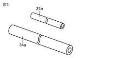
- the gas-liquid two-phase distributor 33 has a distributor 33 a and capillary tubes 34 .
- each of the plurality of first heat transfer tubes T1 and the plurality of first connection portions C1 is a circular tube.
- Each of the plurality of second heat transfer tubes T2 and the plurality of second connection portions C2 is a circular tube.
- the capillary tubes 34 are connected to the first heat exchange sections 31a of the first row and the second heat exchange sections 31b of the second row. It includes a second capillary tube 34b.
- the inner diameter of the first capillary tube 34a may be larger than the inner diameter of the second capillary tube 34b.
- the length of the first capillary tube 34a may be longer than the length of the second capillary tube 34b.
- first heat transfer tube T1 and second heat transfer tube T2 of heat exchanger HE are flat tubes. be.
- FIG. 1 the operation of the refrigeration cycle apparatus 100 according to Embodiment 1 will be described with reference to FIGS. 1 to 3.
- FIG. 1 the operation of the refrigeration cycle apparatus 100 according to Embodiment 1 will be described with reference to FIGS. 1 to 3.
- the refrigeration cycle device 100 can selectively perform cooling operation and heating operation.
- refrigerant circulates through the refrigerant circuit 10 in the order of the compressor 1, the four-way valve 2, the outdoor heat exchanger 3, the expansion valve 4, the indoor heat exchanger 5, and the four-way valve 2.
- the outdoor heat exchanger 3 functions as a condenser. Heat exchange is performed between the refrigerant flowing through the outdoor heat exchanger 3 and the air blown by the outdoor fan 6 .
- the indoor heat exchanger 5 functions as an evaporator. Heat exchange is performed between the refrigerant flowing through the indoor heat exchanger 5 and the air blown by the indoor blower 7 .
- the high-pressure gas refrigerant discharged from the compressor 1 passes through the header distributor 32 of the heat exchanger HE, and passes through the first heat transfer tube T1 of the first heat exchange section 31a of the first row and the second heat exchanger of the second row. It flows into the second heat transfer tube T2 of the portion 31b and flows perpendicularly to the air flow.
- the flow resistance of the first capillary tube 34a installed on the outlet side of the first heat exchange section 31a is replaced by the flow resistance of the second capillary tube 34b installed on the outlet side of the second heat exchange section 31b. , more refrigerant flows through the first capillary tube 34a than through the second capillary tube 34b.
- the high-pressure gas refrigerant becomes a high-pressure liquid refrigerant by exchanging heat with the air through the plurality of first fins F1, the plurality of first heat transfer tubes T1, the plurality of second fins F2, and the plurality of second heat transfer tubes T2. .
- the refrigerant circulates through the refrigerant circuit 10 in the order of the compressor 1, the four-way valve 2, the indoor heat exchanger 5, the expansion valve 4, the outdoor heat exchanger 3, and the four-way valve 2.
- the indoor heat exchanger 5 functions as a condenser. Heat exchange is performed between the refrigerant flowing through the indoor heat exchanger 5 and the air blown by the indoor blower 7 .
- the outdoor heat exchanger 3 functions as an evaporator. Heat exchange is performed between the refrigerant flowing through the outdoor heat exchanger 3 and the air blown by the outdoor fan 6 .
- the low-pressure gas-liquid two-phase refrigerant with low dryness is depressurized by the distributor 33a of the gas-liquid two-phase distributor 33 of the heat exchanger HE and stirred, so that the gas-liquid two-phase spray state is distributed with equal dryness. be done.
- the flow resistance of the first capillary tubes 34a connected to the first heat exchange portions 31a of the first row is set higher than the flow resistance of the second capillary tubes 34b connected to the second heat exchange portions 31b of the second row. By reducing the size, more coolant flows through the first capillary tube 34a than through the second capillary tube 34b.
- the low-pressure gas-liquid two-phase refrigerant with low dryness exchanges heat with the air via the plurality of first fins F1, the plurality of first heat transfer tubes T1, the plurality of first fins F1, and the plurality of second heat transfer tubes T2. becomes a low-pressure gas refrigerant.
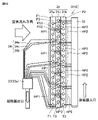
- a plurality of header distributors 32 and gas-liquid two-phase distributors 33 are arranged for each row.
- two header distributors 32 and two gas-liquid two-phase distributors 33 are arranged.
- Two electronic expansion valves 35 are arranged downstream of each of the two gas-liquid two-phase distributors 33, respectively.
- the inner diameter of the first capillary tube 34a connected to the first heat exchange section 31a in the first row is the second diameter connected to the second heat exchange section 31b in the second row. It is made larger than the inner diameter of the capillary tube 34b. Furthermore, the length of the first capillary tubes 34a connected to the first heat exchange sections 31a in the first row is longer than the length of the second capillary tubes 34b connected to the second heat exchange sections 31b in the second row. do.
- the plurality of first fins F1 are corrugated fins.
- the multiple first heat transfer tubes T1 are straight flat tubes.
- Each of the plurality of first fins F1 is arranged between each of the plurality of first heat transfer tubes T1.
- Headers 36 are connected to both ends of each of the plurality of first heat transfer tubes T1.
- Refrigerant temperature in each path with respect to the refrigerant flow when the heat exchanger HE in this embodiment functions as a condenser or an evaporator will be described with reference to FIG.
- the refrigerant temperature decreases in both the first and second rows as the refrigerant flow increases.
- the coolant temperature in the first row will be lower than the coolant temperature in the second row.
- the refrigerant temperature increases in both the first and second rows as the refrigerant flow increases.
- the coolant temperature in the first row will be higher than the coolant temperature in the second row.
- the flow of the non-azeotropic refrigerant mixture flowing through the plurality of first heat transfer tubes T1 is combined with the flow of air flowing through the first heat transfer section HP1. It has a plurality of first heat transfer tubes T1 arranged so as to be orthogonal to each other. Therefore, the flow of the non-azeotropic refrigerant mixture becomes a cross flow with respect to the air flow. This makes it possible to increase the heat exchange efficiency compared to co-flow when the heat exchanger HE functions as either a condenser or an evaporator. Therefore, it is possible to secure an average heat exchange efficiency in the condenser and the evaporator while using the non-azeotropic mixed refrigerant.
- the gas-liquid two-phase distributor 33 increases the pressure loss of the high-pressure gas refrigerant in the condenser.
- the amount of refrigerant increases due to the increased capacity of the outlet header.
- the pressure loss in the extension pipe increases.
- the flow resistance of the first capillary tube 34a smaller than the flow resistance of the second capillary tube 34b, more refrigerant can flow through the first heat transfer tubes T1 in the first row, which have a large heat load. Therefore, since the difference in refrigerant outlet temperature between the first heat transfer tubes T1 of the first row and the second heat transfer tubes T2 of the second row is small, the heat exchange efficiency can be increased.
- the refrigeration cycle apparatus 100 includes the heat exchanger HE described above. For this reason, it is possible to provide the refrigeration cycle apparatus 100 including the heat exchanger HE that can maintain the average heat exchange efficiency in the condenser and the evaporator while using a non-azeotropic mixed refrigerant.
- Embodiment 2 The heat exchanger HE according to the second embodiment has the same configuration, operation and effects as the heat exchanger HE according to the first embodiment unless otherwise specified.
- first heat transfer section HP1 and second heat transfer section HP2 are arranged on opposite sides of each other. are placed.
- the refrigerant inlet is arranged at the uppermost stage, and the refrigerant outlet is arranged at the lowermost stage.
- the refrigerant inlet is arranged at the lowest stage, and the refrigerant outlet is arranged at the uppermost stage. That is, the inlets and outlets of the non-azeotropic refrigerant mixture of the first heat transfer section HP1 and the second heat transfer section HP2 are arranged upside down.
- the heat exchange section 31 includes a third heat exchange section 31c.
- the third heat exchange portion 31c is arranged on the windward side of the first heat exchange portion 31a in the air flow direction D1.
- the third heat exchange portions 31c are arranged in the first row in the air flow direction D1.
- the third heat exchange section 31c includes a third heat transfer section HP3.
- the third heat exchange section 31c includes a plurality of third heat transfer sections HP3.
- the third heat exchange portion 31c has a plurality of third fins F3, a plurality of third heat transfer tubes T3, and a plurality of third connection portions C3 (not shown).
- the plurality of third fins F3, the plurality of third heat transfer tubes T3, and the plurality of third connection portions C3 (not shown) are composed of the plurality of first fins F1, the plurality of first heat transfer tubes T1, and the plurality of It is configured in the same manner as the first connection portion C1 (not shown).
- the non-azeotropic refrigerant mixture flows through the plurality of third heat transfer tubes T3 of the third heat transfer portion HP3.
- the non-azeotropic refrigerant mixture continuously flows through the plurality of third heat transfer tubes T3 and the plurality of third connection portions C3 (not shown).
- the capillary tube 34 includes a third capillary tube 34c connected to the third heat exchange section 31c.
- the inner diameter of the third capillary tube 34c may be larger than the inner diameter of the first capillary tube 34a.
- the length of the third capillary tube 34c may be longer than the length of the first capillary tube 34a.
- the refrigerant temperature in each path with respect to the refrigerant flow when the heat exchanger HE in this embodiment functions as a condenser or an evaporator will be described.
- the difference in refrigerant temperature between the first and second rows is smaller in both the condenser and the evaporator.
- the non-azeotropic mixed refrigerant inlets and outlets of the first heat transfer section HP1 and the second heat transfer section HP2 are arranged on opposite sides of each other. Therefore, it is possible to average the temperature distribution of the blown air in the height direction of the heat exchanger HE.
- the heat exchanger HE when the heat exchanger HE is applied to the outdoor heat exchanger 3, the amount of frost formed when the outside air is low is uniformed, so the average heating capacity can be improved. In addition, when the heat exchanger HE is applied to the indoor heat exchanger 5, dewdrops are less likely to occur, so comfort and quality performance can be improved.
- Embodiment 3 The heat exchanger HE according to the third embodiment has the same configuration, operation and effects as the heat exchangers HE according to the first and second embodiments unless otherwise specified.
- the first heat transfer section HP1 and the second heat transfer section HP2 have a first pass PS1 and a second pass PS2.
- the first pass PS1 the flow of the non-azeotropic refrigerant mixture flowing through the plurality of first heat transfer tubes T1 and the plurality of second heat transfer tubes T2 is combined with the flow of air flowing through the first heat transfer section HP1 and the second heat transfer section HP2. are arranged parallel to each other.
- the flow of the non-azeotropic refrigerant mixture flowing through the plurality of first heat transfer tubes T1 and the plurality of second heat transfer tubes T2 is combined with the flow of air flowing through the first heat transfer section HP1 and the second heat transfer section HP2. are arranged to face each other.
- a first pass PS1 and a second pass PS2 are combined.
- heat exchanging portion 31 includes a third heat exchanging portion 31c.
- the third heat exchange portion 31c is arranged between the first heat exchange portion 31a and the second heat exchange portion 31b in the air flow direction D1.
- the refrigerant temperature in each path with respect to the refrigerant flow when the heat exchanger HE in this embodiment functions as a condenser or an evaporator will be described.
- the difference in refrigerant temperature between the first and second rows is smaller in both the condenser and the evaporator.
- the flow of the non-azeotropic refrigerant mixture flowing through the plurality of first heat transfer tubes T1 and the plurality of second heat transfer tubes T2 reaches the first heat transfer section. It is arranged so as to be parallel to the flow of air flowing through HP1 and second heat transfer part HP2.
- the flow of the non-azeotropic refrigerant mixture flowing through the plurality of first heat transfer tubes T1 and the plurality of second heat transfer tubes T2 is combined with the flow of air flowing through the first heat transfer section HP1 and the second heat transfer section HP2. are arranged to face each other. Therefore, it is possible to further average the temperature distribution of the blown air in the height direction of the heat exchanger HE. As a result, the heat load of each path is further uniformed, so that the heat exchange efficiency can be improved.
- the heat exchanger HE when the heat exchanger HE is applied to the outdoor heat exchanger 3, the amount of frost formed when the outside air is low is uniformed, so the average heating capacity can be improved. In addition, when the heat exchanger HE is applied to the indoor heat exchanger 5, dewdrops are less likely to occur, so comfort and quality performance can be improved.
Abstract
Description
図1を参照して、実施の形態1に係る冷凍サイクル装置100の構成について説明する。実施の形態1では、冷凍サイクル装置100の一例として空気調和機について説明する。図1中実線矢印は、冷房運転時における冷媒の流れを示している。図1中破線矢印は、暖房運転時における冷媒の流れを示している。
A configuration of a
図9を参照して、凝縮器および蒸発器の対向流、並行流、直交流の熱交換効率について説明する。対向流、並行流、直交流は、空気流れに対する冷媒流れの関係を示している。凝縮器および蒸発器のいずれにおいても、対向流、直交流、並行流の順に熱交換効率が低下する。 Next, the effects of this embodiment will be described.
With reference to FIG. 9, the heat exchange efficiencies of counterflow, parallel flow, and crossflow of the condenser and evaporator will be described. Counterflow, cocurrent flow, and crossflow refer to the relationship of refrigerant flow to air flow. In both condensers and evaporators, the heat exchange efficiency decreases in the order of counter flow, cross flow, and parallel flow.
実施の形態2に係る熱交換器HEは、特に説明しない限り、実施の形態1に係る熱交換器HEと同一の構成、動作および作用効果を有している。
The heat exchanger HE according to the second embodiment has the same configuration, operation and effects as the heat exchanger HE according to the first embodiment unless otherwise specified.
図13を参照して、本実施の形態での熱交換器HEが凝縮器または蒸発器として機能するときの冷媒流れに対する各パスの冷媒温度について説明する。実施の形態1に比べて、凝縮器および蒸発器のいずれでも第1列および第2列の冷媒温度の差異が小さくなる。 Next, the effects of this embodiment will be described.
Referring to FIG. 13, the refrigerant temperature in each path with respect to the refrigerant flow when the heat exchanger HE in this embodiment functions as a condenser or an evaporator will be described. Compared to the first embodiment, the difference in refrigerant temperature between the first and second rows is smaller in both the condenser and the evaporator.
実施の形態3に係る熱交換器HEは、特に説明しない限り、実施の形態1および2に係る熱交換器HEと同一の構成、動作および作用効果を有している。
The heat exchanger HE according to the third embodiment has the same configuration, operation and effects as the heat exchangers HE according to the first and second embodiments unless otherwise specified.
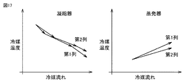
図17を参照して、本実施の形態での熱交換器HEが凝縮器または蒸発器として機能するときの冷媒流れに対する各パスの冷媒温度について説明する。実施の形態1に比べて、凝縮器および蒸発器のいずれでも第1列および第2列の冷媒温度の差異が小さくなる。 Next, the effects of this embodiment will be described.
Referring to FIG. 17, the refrigerant temperature in each path with respect to the refrigerant flow when the heat exchanger HE in this embodiment functions as a condenser or an evaporator will be described. Compared to the first embodiment, the difference in refrigerant temperature between the first and second rows is smaller in both the condenser and the evaporator.
Claims (5)
- 複数の第1伝熱管を有する第1伝熱部と、
前記第1伝熱部の前記複数の第1伝熱管を流れる非共沸混合冷媒とを備え、
前記複数の第1伝熱管は一列に並んで配置されており、
前記第1伝熱部は、前記複数の第1伝熱管を流れる前記非共沸混合冷媒の流れが前記第1伝熱部を流れる空気の流れに対して直交するように配置された前記複数の第1伝熱管を有している、熱交換器。 a first heat transfer section having a plurality of first heat transfer tubes;
a non-azeotropic refrigerant mixture flowing through the plurality of first heat transfer tubes of the first heat transfer section;
The plurality of first heat transfer tubes are arranged in a row,
The first heat transfer section is arranged such that the flow of the non-azeotropic refrigerant mixture flowing through the plurality of first heat transfer tubes is orthogonal to the flow of air flowing through the first heat transfer section. A heat exchanger having a first heat transfer tube. - 複数の第2伝熱管を有する第2伝熱部をさらに備え、
前記第2伝熱部は、前記第1伝熱部と隣り合うように配置されており、
前記複数の第2伝熱管は一列に並んで配置されており、かつ前記複数の第1伝熱管が並ぶ方向に沿って並んで配置されており、
前記非共沸混合冷媒は、前記第2伝熱部の前記複数の第2伝熱管を流れ、
前記第2伝熱部は、前記複数の第2伝熱管を流れる前記非共沸混合冷媒の流れが前記第2伝熱部を流れる空気の流れに対して直交するように配置された前記複数の第2伝熱管を有している、請求項1に記載の熱交換器。 Further comprising a second heat transfer section having a plurality of second heat transfer tubes,
The second heat transfer section is arranged adjacent to the first heat transfer section,
The plurality of second heat transfer tubes are arranged in a row, and are arranged along the direction in which the plurality of first heat transfer tubes are arranged,
The non-azeotropic refrigerant mixture flows through the plurality of second heat transfer tubes of the second heat transfer section,
The second heat transfer section is arranged such that the flow of the non-azeotropic refrigerant mixture flowing through the plurality of second heat transfer tubes is orthogonal to the flow of air flowing through the second heat transfer section. 2. The heat exchanger of claim 1, comprising a second heat transfer tube. - 前記第1伝熱部および前記第2伝熱部の各々の前記非共沸混合冷媒の入口および出口は、互いに反対側に配置されている、請求項2に記載の熱交換器。 3. The heat exchanger according to claim 2, wherein the non-azeotrope refrigerant inlet and outlet of each of the first heat transfer section and the second heat transfer section are arranged opposite to each other.
- 前記第1伝熱部および前記第2伝熱部は、第1パスおよび第2パスを有し、
前記第1パスは、前記複数の第1伝熱管および前記複数の第2伝熱管を流れる前記非共沸混合冷媒の流れが前記第1伝熱部および前記第2伝熱部を流れる空気の流れに対して並行するように配置されており、
前記第2パスは、前記複数の第1伝熱管および前記複数の第2伝熱管を流れる前記非共沸混合冷媒の流れが前記第1伝熱部および前記第2伝熱部を流れる空気の流れに対して対向するように配置されている、請求項2または3に記載の熱交換器。 The first heat transfer section and the second heat transfer section have a first pass and a second pass,
In the first pass, the flow of the non-azeotropic refrigerant mixture flowing through the plurality of first heat transfer tubes and the plurality of second heat transfer tubes is the flow of air flowing through the first heat transfer section and the second heat transfer section. are arranged parallel to the
In the second pass, the flow of the non-azeotropic refrigerant mixture flowing through the plurality of first heat transfer tubes and the plurality of second heat transfer tubes is the flow of air flowing through the first heat transfer section and the second heat transfer section. 4. A heat exchanger according to claim 2 or 3, arranged opposite to the - 請求項1~4のいずれか1項に記載の前記熱交換器と、
前記熱交換器に流入する前記非共沸混合冷媒を圧縮するための圧縮機とを備えた、冷凍サイクル装置。 The heat exchanger according to any one of claims 1 to 4;
and a compressor for compressing the non-azeotropic refrigerant mixture flowing into the heat exchanger.
Priority Applications (3)
| Application Number | Priority Date | Filing Date | Title |
|---|---|---|---|
| CN202180100132.XA CN117642595A (en) | 2021-07-07 | 2021-07-07 | Heat exchanger and refrigeration cycle device |
| PCT/JP2021/025606 WO2023281656A1 (en) | 2021-07-07 | 2021-07-07 | Heat exchanger and refrigeration cycle device |
| JP2023532947A JPWO2023281656A1 (en) | 2021-07-07 | 2021-07-07 |
Applications Claiming Priority (1)
| Application Number | Priority Date | Filing Date | Title |
|---|---|---|---|
| PCT/JP2021/025606 WO2023281656A1 (en) | 2021-07-07 | 2021-07-07 | Heat exchanger and refrigeration cycle device |
Publications (1)
| Publication Number | Publication Date |
|---|---|
| WO2023281656A1 true WO2023281656A1 (en) | 2023-01-12 |
Family
ID=84800477
Family Applications (1)
| Application Number | Title | Priority Date | Filing Date |
|---|---|---|---|
| PCT/JP2021/025606 WO2023281656A1 (en) | 2021-07-07 | 2021-07-07 | Heat exchanger and refrigeration cycle device |
Country Status (3)
| Country | Link |
|---|---|
| JP (1) | JPWO2023281656A1 (en) |
| CN (1) | CN117642595A (en) |
| WO (1) | WO2023281656A1 (en) |
Citations (12)
| Publication number | Priority date | Publication date | Assignee | Title |
|---|---|---|---|---|
| JPS5862469A (en) * | 1981-10-08 | 1983-04-13 | 三菱重工業株式会社 | Heat pump type refrigerator |
| JPH06194000A (en) * | 1992-12-24 | 1994-07-15 | Hitachi Ltd | Air conditioner |
| JPH06265228A (en) * | 1993-03-15 | 1994-09-20 | Matsushita Electric Ind Co Ltd | Refrigerating device |
| JPH06307725A (en) * | 1993-04-21 | 1994-11-01 | Hitachi Ltd | Air conditioner |
| JPH0798162A (en) * | 1993-09-29 | 1995-04-11 | Toshiba Corp | Air-conditioner |
| JPH07294043A (en) * | 1994-04-28 | 1995-11-10 | Sanyo Electric Co Ltd | Air conditioner |
| JP2001050685A (en) * | 1999-08-06 | 2001-02-23 | Sanyo Electric Co Ltd | Heat exchanger |
| JP2007155175A (en) * | 2005-12-02 | 2007-06-21 | Showa Tansan Co Ltd | Heat pump system, air conditioner or refrigerating machine system using zeotropic refrigerant mixture |
| JP2014040983A (en) | 2012-08-23 | 2014-03-06 | Daikin Ind Ltd | Heat exchanger of air conditioning apparatus |
| WO2019043768A1 (en) * | 2017-08-29 | 2019-03-07 | 三菱電機株式会社 | Condenser and refrigeration device provided with condenser |
| WO2020021593A1 (en) * | 2018-07-23 | 2020-01-30 | 三菱電機株式会社 | Air-conditioning apparatus |
| WO2021131038A1 (en) * | 2019-12-27 | 2021-07-01 | 三菱電機株式会社 | Heat exchanger and refrigeration cycle device |
-
2021
- 2021-07-07 WO PCT/JP2021/025606 patent/WO2023281656A1/en active Application Filing
- 2021-07-07 CN CN202180100132.XA patent/CN117642595A/en active Pending
- 2021-07-07 JP JP2023532947A patent/JPWO2023281656A1/ja active Pending
Patent Citations (12)
| Publication number | Priority date | Publication date | Assignee | Title |
|---|---|---|---|---|
| JPS5862469A (en) * | 1981-10-08 | 1983-04-13 | 三菱重工業株式会社 | Heat pump type refrigerator |
| JPH06194000A (en) * | 1992-12-24 | 1994-07-15 | Hitachi Ltd | Air conditioner |
| JPH06265228A (en) * | 1993-03-15 | 1994-09-20 | Matsushita Electric Ind Co Ltd | Refrigerating device |
| JPH06307725A (en) * | 1993-04-21 | 1994-11-01 | Hitachi Ltd | Air conditioner |
| JPH0798162A (en) * | 1993-09-29 | 1995-04-11 | Toshiba Corp | Air-conditioner |
| JPH07294043A (en) * | 1994-04-28 | 1995-11-10 | Sanyo Electric Co Ltd | Air conditioner |
| JP2001050685A (en) * | 1999-08-06 | 2001-02-23 | Sanyo Electric Co Ltd | Heat exchanger |
| JP2007155175A (en) * | 2005-12-02 | 2007-06-21 | Showa Tansan Co Ltd | Heat pump system, air conditioner or refrigerating machine system using zeotropic refrigerant mixture |
| JP2014040983A (en) | 2012-08-23 | 2014-03-06 | Daikin Ind Ltd | Heat exchanger of air conditioning apparatus |
| WO2019043768A1 (en) * | 2017-08-29 | 2019-03-07 | 三菱電機株式会社 | Condenser and refrigeration device provided with condenser |
| WO2020021593A1 (en) * | 2018-07-23 | 2020-01-30 | 三菱電機株式会社 | Air-conditioning apparatus |
| WO2021131038A1 (en) * | 2019-12-27 | 2021-07-01 | 三菱電機株式会社 | Heat exchanger and refrigeration cycle device |
Also Published As
| Publication number | Publication date |
|---|---|
| CN117642595A (en) | 2024-03-01 |
| JPWO2023281656A1 (en) | 2023-01-12 |
Similar Documents
| Publication | Publication Date | Title |
|---|---|---|
| US9702637B2 (en) | Heat exchanger, indoor unit, and refrigeration cycle apparatus | |
| WO2016056064A1 (en) | Heat exchanger and air conditioning device | |
| US20090314020A1 (en) | Indoor unit for air conditioner | |
| WO2014181400A1 (en) | Heat exchanger and refrigeration cycle device | |
| JP2011127831A (en) | Heat exchanger and refrigerating cycle device including the same | |
| JP6793831B2 (en) | Heat exchanger and refrigeration cycle equipment | |
| US20230128871A1 (en) | Heat exchanger, outdoor unit, and refrigeration cycle device | |
| WO2023281656A1 (en) | Heat exchanger and refrigeration cycle device | |
| US11384996B2 (en) | Heat exchanger and refrigeration cycle apparatus | |
| WO2022264348A1 (en) | Heat exchanger and refrigeration cycle device | |
| JP6987227B2 (en) | Heat exchanger and refrigeration cycle equipment | |
| CN110285603B (en) | Heat exchanger and refrigeration system using same | |
| JP7292389B2 (en) | Heat exchanger and refrigeration cycle equipment | |
| WO2019155571A1 (en) | Heat exchanger and refrigeration cycle device | |
| WO2021245877A1 (en) | Heat exchanger and refrigeration cycle device | |
| WO2023188421A1 (en) | Outdoor unit and air conditioner equipped with same | |
| JP7118279B2 (en) | HEAT EXCHANGER, MANUFACTURING METHOD THEREOF, AND AIR CONDITIONER | |
| WO2023281655A1 (en) | Heat exchanger and refrigeration cycle device | |
| WO2022215193A1 (en) | Refrigeration cycle device | |
| WO2023030508A1 (en) | Heat exchanger and multi-system air conditioning unit | |
| WO2023199466A1 (en) | Heat exchanger, and air conditioning device including same | |
| WO2021171446A1 (en) | Heat exchanger of heat source-side unit, and heat pump device equipped with said heat exchanger | |
| JP7305085B1 (en) | Heat exchanger and refrigeration cycle equipment | |
| WO2023233572A1 (en) | Heat exchanger, and refrigeration cycle device | |
| JP7150157B2 (en) | Heat exchanger and refrigeration cycle equipment |
Legal Events
| Date | Code | Title | Description |
|---|---|---|---|
| 121 | Ep: the epo has been informed by wipo that ep was designated in this application |
Ref document number: 21949290 Country of ref document: EP Kind code of ref document: A1 |
|
| WWE | Wipo information: entry into national phase |
Ref document number: 2301008182 Country of ref document: TH |
|
| WWE | Wipo information: entry into national phase |
Ref document number: 2023532947 Country of ref document: JP |
|
| WWE | Wipo information: entry into national phase |
Ref document number: 2021949290 Country of ref document: EP |
|
| ENP | Entry into the national phase |
Ref document number: 2021949290 Country of ref document: EP Effective date: 20240207 |
|
| NENP | Non-entry into the national phase |
Ref country code: DE |