JPWO2005073798A1 - Light source device and two-dimensional image display device - Google Patents
Light source device and two-dimensional image display device Download PDFInfo
- Publication number
- JPWO2005073798A1 JPWO2005073798A1 JP2005517447A JP2005517447A JPWO2005073798A1 JP WO2005073798 A1 JPWO2005073798 A1 JP WO2005073798A1 JP 2005517447 A JP2005517447 A JP 2005517447A JP 2005517447 A JP2005517447 A JP 2005517447A JP WO2005073798 A1 JPWO2005073798 A1 JP WO2005073798A1
- Authority
- JP
- Japan
- Prior art keywords
- light
- light source
- source device
- emitted
- volume hologram
- Prior art date
- Legal status (The legal status is an assumption and is not a legal conclusion. Google has not performed a legal analysis and makes no representation as to the accuracy of the status listed.)
- Granted
Links
Images


Classifications
-
- G—PHYSICS
- G03—PHOTOGRAPHY; CINEMATOGRAPHY; ANALOGOUS TECHNIQUES USING WAVES OTHER THAN OPTICAL WAVES; ELECTROGRAPHY; HOLOGRAPHY
- G03B—APPARATUS OR ARRANGEMENTS FOR TAKING PHOTOGRAPHS OR FOR PROJECTING OR VIEWING THEM; APPARATUS OR ARRANGEMENTS EMPLOYING ANALOGOUS TECHNIQUES USING WAVES OTHER THAN OPTICAL WAVES; ACCESSORIES THEREFOR
- G03B21/00—Projectors or projection-type viewers; Accessories therefor
-
- G—PHYSICS
- G02—OPTICS
- G02B—OPTICAL ELEMENTS, SYSTEMS OR APPARATUS
- G02B27/00—Optical systems or apparatus not provided for by any of the groups G02B1/00 - G02B26/00, G02B30/00
- G02B27/10—Beam splitting or combining systems
- G02B27/1006—Beam splitting or combining systems for splitting or combining different wavelengths
- G02B27/102—Beam splitting or combining systems for splitting or combining different wavelengths for generating a colour image from monochromatic image signal sources
- G02B27/1046—Beam splitting or combining systems for splitting or combining different wavelengths for generating a colour image from monochromatic image signal sources for use with transmissive spatial light modulators
- G02B27/1053—Beam splitting or combining systems for splitting or combining different wavelengths for generating a colour image from monochromatic image signal sources for use with transmissive spatial light modulators having a single light modulator for all colour channels
-
- G—PHYSICS
- G02—OPTICS
- G02B—OPTICAL ELEMENTS, SYSTEMS OR APPARATUS
- G02B27/00—Optical systems or apparatus not provided for by any of the groups G02B1/00 - G02B26/00, G02B30/00
- G02B27/10—Beam splitting or combining systems
- G02B27/1073—Beam splitting or combining systems characterized by manufacturing or alignment methods
-
- G—PHYSICS
- G02—OPTICS
- G02B—OPTICAL ELEMENTS, SYSTEMS OR APPARATUS
- G02B27/00—Optical systems or apparatus not provided for by any of the groups G02B1/00 - G02B26/00, G02B30/00
- G02B27/10—Beam splitting or combining systems
- G02B27/1086—Beam splitting or combining systems operating by diffraction only
- G02B27/1093—Beam splitting or combining systems operating by diffraction only for use with monochromatic radiation only, e.g. devices for splitting a single laser source
-
- G—PHYSICS
- G02—OPTICS
- G02B—OPTICAL ELEMENTS, SYSTEMS OR APPARATUS
- G02B27/00—Optical systems or apparatus not provided for by any of the groups G02B1/00 - G02B26/00, G02B30/00
- G02B27/10—Beam splitting or combining systems
- G02B27/14—Beam splitting or combining systems operating by reflection only
- G02B27/149—Beam splitting or combining systems operating by reflection only using crossed beamsplitting surfaces, e.g. cross-dichroic cubes or X-cubes
-
- G—PHYSICS
- G03—PHOTOGRAPHY; CINEMATOGRAPHY; ANALOGOUS TECHNIQUES USING WAVES OTHER THAN OPTICAL WAVES; ELECTROGRAPHY; HOLOGRAPHY
- G03B—APPARATUS OR ARRANGEMENTS FOR TAKING PHOTOGRAPHS OR FOR PROJECTING OR VIEWING THEM; APPARATUS OR ARRANGEMENTS EMPLOYING ANALOGOUS TECHNIQUES USING WAVES OTHER THAN OPTICAL WAVES; ACCESSORIES THEREFOR
- G03B21/00—Projectors or projection-type viewers; Accessories therefor
- G03B21/14—Details
- G03B21/20—Lamp housings
- G03B21/208—Homogenising, shaping of the illumination light
-
- G—PHYSICS
- G03—PHOTOGRAPHY; CINEMATOGRAPHY; ANALOGOUS TECHNIQUES USING WAVES OTHER THAN OPTICAL WAVES; ELECTROGRAPHY; HOLOGRAPHY
- G03B—APPARATUS OR ARRANGEMENTS FOR TAKING PHOTOGRAPHS OR FOR PROJECTING OR VIEWING THEM; APPARATUS OR ARRANGEMENTS EMPLOYING ANALOGOUS TECHNIQUES USING WAVES OTHER THAN OPTICAL WAVES; ACCESSORIES THEREFOR
- G03B33/00—Colour photography, other than mere exposure or projection of a colour film
- G03B33/10—Simultaneous recording or projection
- G03B33/12—Simultaneous recording or projection using beam-splitting or beam-combining systems, e.g. dichroic mirrors
-
- H—ELECTRICITY
- H04—ELECTRIC COMMUNICATION TECHNIQUE
- H04N—PICTORIAL COMMUNICATION, e.g. TELEVISION
- H04N5/00—Details of television systems
- H04N5/74—Projection arrangements for image reproduction, e.g. using eidophor
-
- H—ELECTRICITY
- H04—ELECTRIC COMMUNICATION TECHNIQUE
- H04N—PICTORIAL COMMUNICATION, e.g. TELEVISION
- H04N9/00—Details of colour television systems
- H04N9/12—Picture reproducers
- H04N9/31—Projection devices for colour picture display, e.g. using electronic spatial light modulators [ESLM]
- H04N9/3102—Projection devices for colour picture display, e.g. using electronic spatial light modulators [ESLM] using two-dimensional electronic spatial light modulators
- H04N9/3111—Projection devices for colour picture display, e.g. using electronic spatial light modulators [ESLM] using two-dimensional electronic spatial light modulators for displaying the colours sequentially, e.g. by using sequentially activated light sources
- H04N9/3114—Projection devices for colour picture display, e.g. using electronic spatial light modulators [ESLM] using two-dimensional electronic spatial light modulators for displaying the colours sequentially, e.g. by using sequentially activated light sources by using a sequential colour filter producing one colour at a time
-
- H—ELECTRICITY
- H04—ELECTRIC COMMUNICATION TECHNIQUE
- H04N—PICTORIAL COMMUNICATION, e.g. TELEVISION
- H04N9/00—Details of colour television systems
- H04N9/12—Picture reproducers
- H04N9/31—Projection devices for colour picture display, e.g. using electronic spatial light modulators [ESLM]
- H04N9/3129—Projection devices for colour picture display, e.g. using electronic spatial light modulators [ESLM] scanning a light beam on the display screen
-
- H—ELECTRICITY
- H04—ELECTRIC COMMUNICATION TECHNIQUE
- H04N—PICTORIAL COMMUNICATION, e.g. TELEVISION
- H04N9/00—Details of colour television systems
- H04N9/12—Picture reproducers
- H04N9/31—Projection devices for colour picture display, e.g. using electronic spatial light modulators [ESLM]
- H04N9/3141—Constructional details thereof
- H04N9/315—Modulator illumination systems
Abstract
2次元画像表示装置をできるだけ小型化することが可能な光源装置を提供する。 赤色、青色、緑色の3つのコヒーレント光源(11a),(11b),(11c)と、該コヒーレント光源(11a),(11c)から出射された光を反射するプリズム(12a),(12c)と、前記コヒーレント光源(11b)から出射された光、及び前記コヒーレント光源(11a),(11c)から出射され、プリズム(12a),(12b)で反射された光を、これらの光が同一光路を伝搬するように回折する、複数のグレーティングが多重形成された1枚の体積ホログラムからなる回折部(20)とを備えた。Provided is a light source device capable of miniaturizing a two-dimensional image display device as much as possible. Three coherent light sources (11a), (11b), (11c) of red, blue, and green, and prisms (12a), (12c) that reflect light emitted from the coherent light sources (11a), (11c) The light emitted from the coherent light source (11b) and the light emitted from the coherent light sources (11a) and (11c) and reflected by the prisms (12a) and (12b) are transmitted through the same optical path. And a diffractive portion (20) composed of a single volume hologram in which a plurality of gratings are formed in a multiplex manner, which diffracts so as to propagate.
Description
本発明は、光源装置及び2次元画像表示装置に関し、特に2次元画像表示装置の小型化を実現する光源装置、及び該光源装置を用いた小型の2次元画像表示装置に関する。 The present invention relates to a light source device and a two-dimensional image display device, and more particularly to a light source device that realizes miniaturization of a two-dimensional image display device and a small two-dimensional image display device using the light source device.
近年、鮮やかな色表現が可能な2次元画像表示装置(レーザディスプレイ装置)が注目されている。これは、赤色、緑色、青色の3つのコヒーレント光源(例えば、レーザ光源)を用いたもので、例えば図13のような構成をとる。 In recent years, a two-dimensional image display device (laser display device) capable of vivid color expression has attracted attention. This uses three coherent light sources (for example, laser light sources) of red, green, and blue, and has a configuration as shown in FIG. 13, for example.
図13において、600は従来のレーザ光源を用いた2次元画像表示装置である。この2次元画像表示装置600は、赤色、緑色、青色レーザ光源601a,601b,601cと、ビームエキスパンダ602a,602b,602cと、光インテグレータ603a,603b,603cと、ミラー604a,604cと、拡散板606a,606b,606cと、拡散板移動手段605a,605b,605cと、空間光変調素子607a,607b,607cと、フィールドレンズ608a,608b,608cと、ダイクロイックプリズム609と、投写レンズ610とを有している。 In FIG. 13,
この2次元画像表示装置600では、赤色、緑色、青色レーザ光源601a,601b,601cからの光がそれぞれビームエキスパンダ602a,602b,602cで拡大され、光インテグレータ603a,603b,603cを通過する。光インテグレータ603a,603cを通過した赤色光及び青色光はミラー604a,604cにより光路が90度曲げられて、光インテグレータ603bを通過した緑色光は、光路が折り曲げられることなく、それぞれ、フィールドレンズ608a,608b,608c、拡散板606a,606b,606cを介して空間光変調素子607a,607b,607cを照射する。3種のレーザ光源601a,601b,601cからの光は、光インテグレータ603a,603b,603cを通過することで空間光変調素子607a,607b,607c上での照度分布が一定になる。この空間光変調素子607a,607b,607cでそれぞれ独立に変調された光は、ダイクロイックプリズム609で合波されて、同一光路を伝搬する同軸ビームとなり、さらに投写レンズ610にて拡大投射されてスクリーン61上に結像される。その際、レーザ光干渉性が高いため、スクリーン61に投写された像にはスペックルノイズが重畳される。これを防ぐために拡散板606a,606b,606cを拡散板移動手段605a,605b,605cにて揺動し、スペックルノイズを時間平均するようにしている。 In the two-dimensional
しかし、図13に示すような従来の2次元画像表示装置600では、3種のレーザ光源601a〜601cからの光を拡大して光強度分布を一様にするために、ビームエキスパンダ及び光インテグレータが各々3つ必要となる。さらに、前記3種のレーザ光源からの光を互いに平行で同一光路を伝搬する同軸ビームにするために、当該装置内に多くのレンズやミラーを配置することも必要となる。このため、従来の2次元画像表示装置は、装置全体が大規模となってしまうという課題があった。 However, in the conventional two-dimensional
この課題を解決するために、2次元画像表示装置の光学系を、例えば、図14に示すように、まず赤色、緑色、青色の3色のレーザ光源から出射された光をダイクロイックミラーを用いて混合した後、ビームエキスパンダ、光インテグレータを通過させる構成にすることが考えられる。 In order to solve this problem, the optical system of the two-dimensional image display device, for example, as shown in FIG. 14, first uses a dichroic mirror to emit light emitted from laser light sources of three colors of red, green, and blue. After mixing, it can be considered that the beam expander and the optical integrator are passed.
図14において、700は、従来のレーザ光源を用いた2次元画像表示装置である。この2次元画像表示装置700は、赤色、緑色、青色レーザ光源701a,701b,701cと、コリメートレンズ704a,704b、704cと、第1,第2のダイクロイックミラー705a,705bと、ビームエキスパンダ702と、光インテグレータ703と、投射レンズ710と、液晶パネル71とを有している。 In FIG. 14,
ここでダイクロイックミラーは、ガラス基板上に多層膜を積層して、波長によって透過率を異ならせるものである。図15に示す2次元画像表示装置700の第1のダイクロイックミラー705aは、580nm程度の波長を境に、該波長より短波長の光を反射して長波長の光のみを通過させるもの、第2のダイクロイックミラー705bは、490nm程度の波長を境に、該波長より短波長の光を反射して長波長の光のみを通過させるものである。 Here, the dichroic mirror is formed by laminating a multilayer film on a glass substrate and changing the transmittance depending on the wavelength. The first
このような従来のレーザ光源を用いた2次元画像表示装置700では、まず、赤色、緑色、青色レーザ光源701a,701b,701cからの出射光を、コリメートレンズ704a,704b、704cでコリメートし、該コリメートした光を、第1,第2のダイクロイックミラー705a,705bによって、互いに平行で同一光路を伝搬する同軸ビームとした後、ビームエキスパンダ702に入射させる。そして、該ビームエキスパンダ702に入射した光は、ビームエキスパンダ702において拡大された後、光インテグレータ703を通過する。前記光インテグレータ703は、長方形のエレメントレンズが2次元状にアレイ化された2枚のフライアイレンズ703a及び703bと、コリメートレンズ703cとを有しており、1枚目のフライアイレンズ703aの各エレメントレンズ上の光が、2枚目のフライアイレンズ703bによって2次元空間光変調素子上に結像され、これによって、各エレメントレンズ上での光強度分布が2次元空間光変調素子上で多重化されることとなり、2次元空間光変調素子上での光強度分布が一様になるものである。 In the two-dimensional
そして、前記光インテグレータ703を通過して光強度分布が一様にされた光は、投射レンズ710により液晶パネル71上に結像する。
このように、図13のように、各レーザ光源601a〜601cから出射された光をビームエキスパンダ602a〜602cで拡大し、光インテグレータ603a〜603bでその光強度分布を一様にした後、ダイクロイックプリズム609で合波して同軸ビームにするより、図14のように、各レーザ光源701a〜701cから出射された光を、まず第1,第2のダイクロイックミラー705a,705bで合波して同軸ビームにした後、ビームエキスパンダ702で拡大して光インテグレータ703でその光強度分布を一様した方が、2次元画像表示装置全体の装置規模を縮小することができる。 As shown in FIG. 13, the light emitted from each of the
しかし、従来の2次元画像表示装置は、その光学系全体を図14に示すように構成しても、携帯電話等のような小型装置に搭載するには、まだ部品数も多いし、装置規模も大きいという課題がある。 However, even if the conventional two-dimensional image display apparatus is configured as shown in FIG. 14, the number of parts is still large for mounting on a small apparatus such as a mobile phone, and the scale of the apparatus is large. There is also a problem that it is big.
本発明は、前記課題を解決するためになされたものであり、小型装置に搭載可能な超小型の光源装置、及び該光源装置を用いた小型の2次元画像表示装置を提供することを目的とする。 The present invention has been made to solve the above-described problems, and an object thereof is to provide an ultra-small light source device that can be mounted on a small device and a small two-dimensional image display device using the light source device. To do.
前記課題を解決するために、本発明の光源装置は、少なくとも2つのコヒーレント光源と、該少なくとも2つのコヒーレント光源から出射された各光が同一光路を伝搬するよう、少なくとも1つのコヒーレント光源から出射された光を回折する回折部と、を具備するものである。 In order to solve the above-mentioned problems, the light source device of the present invention emits at least two coherent light sources and at least one coherent light source so that each of the lights emitted from the at least two coherent light sources propagates in the same optical path. A diffractive portion that diffracts the reflected light.
これにより、回折部において複数のコヒーレント光源から出射された各光を簡易に合波させることができ、光源装置を超小型化できる。 Thereby, each light radiate | emitted from the several coherent light source in a diffraction part can be combined easily, and a light source device can be reduced in size.
また、本発明の光源装置は、前記少なくとも2つのコヒーレント光源から出射された各光の伝搬光路は、前記回折部上で互いに重なり合うものである。
これにより、当該光源装置をさらに小型化することが可能となる。In the light source device of the present invention, the propagation optical paths of the lights emitted from the at least two coherent light sources overlap each other on the diffraction part.
As a result, the light source device can be further reduced in size.
また、本発明の光源装置は、前記少なくとも2つのコヒーレント光源から出射された各光の伝搬光路の中心軸は、前記回折部上の一点で交わるものである。
これにより、当該光源装置をさらに小型化することが可能となる。In the light source device of the present invention, the central axis of the propagation optical path of each light emitted from the at least two coherent light sources intersects at one point on the diffraction unit.
As a result, the light source device can be further reduced in size.
また、本発明の光源装置は、前記少なくとも2つのコヒーレント光源は、同一のサブマウント上に設置されるものである。 In the light source device of the present invention, the at least two coherent light sources are installed on the same submount.
これにより、1枚のサブマウントの放熱により、3つの光源の放熱を行うことができ、当該光源装置における光源の放熱を簡単な構成により実現できるという効果もある。 Thereby, the heat radiation of the three light sources can be performed by the heat radiation of one submount, and the heat radiation of the light source in the light source device can be realized with a simple configuration.
また、本発明の光源装置は、前記コヒーレント光源は、赤色光を発光するコヒーレント光源と、緑色光を発光するコヒーレント光源と、青色光を発光するコヒーレント光源であるものである。
これにより、RGBの光を点灯する小型の光源装置を提供することができる。In the light source device of the present invention, the coherent light source is a coherent light source that emits red light, a coherent light source that emits green light, and a coherent light source that emits blue light.
Thereby, the small light source device which lights up the RGB light can be provided.
また、本発明の光源装置は、前記回折部を、前記コヒーレント光源のうち、少なくとも1つのコヒーレント光源から出射される光が、該回折部で回折せずに通過するものとしたものである。 In the light source device of the present invention, light emitted from at least one coherent light source among the coherent light sources passes through the diffraction unit without being diffracted by the diffraction unit.
これにより、回折部の作製工程を削減できるため、当該光源装置をより安価に提供できる。 Thereby, since the manufacturing process of a diffraction part can be reduced, the said light source device can be provided more cheaply.
また、本発明の光源装置は、前記回折部は、1つの回折素子で構成され、前記回折素子は、該少なくとも2つのコヒーレント光源から出射された各光が同一光路を伝搬するよう、少なくとも1つのコヒーレント光源から出射された光を回折するものである。
これにより、前記回折部をコンパクトにして、当該光源装置を超小型化することが可能となる。Further, in the light source device of the present invention, the diffractive portion includes one diffractive element, and the diffractive element includes at least one light so that each light emitted from the at least two coherent light sources propagates in the same optical path. It diffracts light emitted from a coherent light source.
As a result, the diffractive portion can be made compact, and the light source device can be miniaturized.
さらに、本発明の光源装置は、前記回折素子は、レンズ作用を更に備えるものである。 Furthermore, in the light source device of the present invention, the diffraction element further includes a lens action.
これにより、前記複数のコヒーレント光源から出射される各光が、前記回折素子の上方の同一平面領域を照射することができる。 Thereby, each light radiate | emitted from these coherent light sources can irradiate the same plane area | region above the said diffraction element.
また、本発明の光源装置は、前記回折部を、受光した少なくとも2つの光が同一光路を伝搬するよう、該受光した少なくとも1つの光を回折する第1の回折素子と、前記少なくとも2つのコヒーレント光源のうちの、少なくとも1つのコヒーレント光源から出射された光を、該各コヒーレント光源からの光の伝搬光路の中心軸が前記第1の回折素子上の一点で交わるように回折する第2の回折素子と、から構成したものである。 In the light source device of the present invention, the first diffraction element that diffracts at least one received light and the at least two coherent so that at least two received light propagates through the same optical path. Second diffraction that diffracts light emitted from at least one coherent light source of the light sources so that a central axis of a propagation path of light from each coherent light source intersects at one point on the first diffraction element It is comprised from the element.
これにより、前記回折部において前記複数のコヒーレント光源からの各光を簡易に同軸ビームにして合波できる小型の光源装置を、より安価に提供できる。 Accordingly, a small light source device that can easily combine the light beams from the plurality of coherent light sources into coaxial beams in the diffraction unit can be provided at a lower cost.
さらに、本発明の光源装置は、前記第2の回折素子は、レンズ作用を更に備え、前記第2の回折素子は、前記少なくとも2つのコヒーレント光源から出射される各光を集光して、該第2の回折素子にて回折された各光が、前記第1の回折素子の同一領域を照射するようにするものである。 Furthermore, in the light source device of the present invention, the second diffractive element further includes a lens action, and the second diffractive element condenses each light emitted from the at least two coherent light sources, and Each light diffracted by the second diffractive element irradiates the same region of the first diffractive element.
これにより、前記複数のコヒーレント光源から出射される各光が、前記第2の回折素子の上方に設けられた第1の回折素子の同一領域を照射するようにすることができる。 Thereby, each light radiate | emitted from these coherent light sources can irradiate the same area | region of the 1st diffraction element provided above the said 2nd diffraction element.
さらに、本発明の光源装置は、前記回折素子は、体積ホログラムであり、該体積ホログラムは、前記少なくとも2つのコヒーレント光源から出射される各光を受光して、該各光の伝搬方向を変化させる複数のグレーティングが多重化されているものである。 Further, in the light source device of the present invention, the diffraction element is a volume hologram, and the volume hologram receives each light emitted from the at least two coherent light sources and changes a propagation direction of each light. A plurality of gratings are multiplexed.
これにより、回折部において前記複数のコヒーレント光源からの各光を簡易に同軸ビームにして合波する光源装置の超小型化を実現することができる。 As a result, it is possible to realize a miniaturization of the light source device that easily combines the light beams from the plurality of coherent light sources into a coaxial beam in the diffraction unit.
さらに、本発明の光源装置は、前記回折素子は、領域分割されており、該回折素子の各分割領域において回折された各光が、同一平面領域を照射するものである。 Further, in the light source device of the present invention, the diffraction element is divided into regions, and each light diffracted in each divided region of the diffraction element irradiates the same plane region.
これにより、前記回折素子に光インテグレータの機能を兼ね備えさせることが可能となり、前記空間に照射される光の強度分布を均等にすることが可能となる。 As a result, the diffraction element can be provided with the function of an optical integrator, and the intensity distribution of the light applied to the space can be made uniform.
さらに、本発明の光源装置は、前記回折素子は、格子状に領域分割されている、ものである。
これにより、前記空間に照射される光の強度分布をさらに均等にすることが可能となる。Furthermore, in the light source device of the present invention, the diffraction element is divided into regions in a lattice shape.
Thereby, the intensity distribution of the light irradiated to the space can be made more uniform.
本発明の2次元画像表示装置は、少なくとも2つのコヒーレント光源と、該少なくとも2つのコヒーレント光源から出射された各光が同一光路を伝搬するよう、少なくとも1つのコヒーレント光源から出射された光を回折する回折部と、該回折部上の空間に設けられ、該回折部で回折され同軸ビームにされた各光を受光する2次元空間光変調素子と、を具備するものである。 The two-dimensional image display apparatus according to the present invention diffracts light emitted from at least one coherent light source so that at least two coherent light sources and each light emitted from the at least two coherent light sources propagates in the same optical path. A diffractive portion; and a two-dimensional spatial light modulation element that is provided in a space on the diffractive portion and receives each light diffracted by the diffractive portion into a coaxial beam.
これにより、光源装置から出射された光を表示する2次元画像表示装置を小型化することができる。 Thereby, the two-dimensional image display apparatus which displays the light radiate | emitted from the light source device can be reduced in size.
また、本発明の2次元画像表示装置は、前記少なくとも2つのコヒーレント光源の動作を制御する制御部を備え、前記少なくとも2つのコヒーレント光源は、赤色光を発光するコヒーレント光源と、緑色光を発光するコヒーレント光源と、青色光を発光するコヒーレント光源であり、前記制御部は、該3つのコヒーレント光源を、時間分割されて順次光を出射するように制御するものである。 The two-dimensional image display device of the present invention includes a control unit that controls operations of the at least two coherent light sources, and the at least two coherent light sources emit a red light and a green light. A coherent light source and a coherent light source that emits blue light, and the control unit controls the three coherent light sources so as to emit light sequentially in a time-division manner.
これにより、当該2次元画像表示装置において動画像も表示可能となる。 Thereby, a moving image can also be displayed on the two-dimensional image display device.
本発明の光源装置によれば、複数のコヒーレント光源を有する光源装置において、前記コヒーレント光源から出射された各光を同一光路を伝搬するように回折する回折部を備えたので、前記複数のコヒーレント光源からの各光を、同軸ビームとなるよう合波する光学系をコンパクトにすることができ、超小型の光源装置を提供することが可能となる。 According to the light source device of the present invention, in the light source device having a plurality of coherent light sources, the diffraction unit that diffracts each light emitted from the coherent light source so as to propagate in the same optical path is provided. It is possible to make the optical system that combines the light from each of the light beams into a coaxial beam compact, and to provide an ultra-small light source device.
また、本発明の光源装置によれば、前記複数のコヒーレント光源のうち、少なくとも1つのコヒーレント光源から出射される光は、前記回折部で回折せず通過するようにしたので、前記回折部に多重化するグレーティングの数を少なくすることができ、当該光源装置を安価に構成することが可能となる。 Also, according to the light source device of the present invention, light emitted from at least one coherent light source among the plurality of coherent light sources passes through without being diffracted by the diffractive part. The number of gratings to be reduced can be reduced, and the light source device can be configured at low cost.
また、本発明の光源装置によれば、回折部を第1及び第2の2つの回折格子により構成し、第2の回折格子を、複数のコヒーレント光源からの光を、これらの光が第1の回折素子の同一領域に照射するよう回折するものとし、第1の回折格子を、前記第2の回折素子を通過した各光を同軸ビームになるよう回折するものとしたので、複数の光源からの光を簡易に同軸ビームになるよう合波することができる小型の光源装置を提供することが可能となる。 Further, according to the light source device of the present invention, the diffractive portion is constituted by the first and second diffraction gratings, the second diffraction grating is made up of light from a plurality of coherent light sources, and these lights are the first. And the first diffraction grating diffracts each light that has passed through the second diffraction element into a coaxial beam. Therefore, it is possible to provide a small light source device that can multiplex the light into a coaxial beam.
また、本発明の光源装置によれば、前記複数のコヒーレント光源を同一サブマウント上に設けるようにしたので、複数の光源の放熱を1枚のサブマウントの放熱により行うことができ、光源装置における放熱処理を容易に行える効果もある。 Further, according to the light source device of the present invention, since the plurality of coherent light sources are provided on the same submount, the heat radiation of the plurality of light sources can be performed by the heat radiation of one submount. There is also an effect that heat treatment can be easily performed.
また、本発明の光源装置によれば、前記回折部を領域分割し、該回折部の各分割領域を、複数のグレーティングが多重形成され、且つ凹レンズ作用を備えたものとしたので、前記複数のコヒーレント光源から出射された各光を簡易に同軸ビームにして合波できることに加え、該回折部から出射される光の強度分布を一様にすることができる。さらに、該回折部から出射される光の強度分布を一様にする光インテグレータを有する回折部は、従来のレンズアレイに比べ、小型で且つ材料に安価なものを利用可能なため、光源装置を安価に実現することができる。 Further, according to the light source device of the present invention, the diffractive portion is divided into regions, and each divided region of the diffractive portion is provided with a plurality of gratings and having a concave lens action. In addition to being able to easily combine the light emitted from the coherent light source into a coaxial beam, the intensity distribution of the light emitted from the diffraction unit can be made uniform. Furthermore, since the diffractive part having an optical integrator that uniformizes the intensity distribution of the light emitted from the diffractive part is smaller and cheaper than the conventional lens array, a light source device can be used. It can be realized at low cost.
また、本発明の2次元画像表示装置によれば、光源装置を、回折素子を用いた小型化されたものとしたので、2次元画像表示装置を小型化することが可能となる。 Further, according to the two-dimensional image display device of the present invention, since the light source device is miniaturized using a diffraction element, the two-dimensional image display device can be miniaturized.
さらに、本発明の2次元画像表示装置によれば、前記光源装置の回折部が、光インテグレータの機能を兼ね備えているため、従来は光強度分布の均一化に必要であったフライアイレンズを用いなくても、光源装置の出力光は強度分布の均一なものとなり、光源光の強度分布が一様である2次元画像表示装置をより小型化できると共に、当該2次元画像表示装置の構成部品数も削減できる。この結果、光源光の強度分布が一様な2次元画像表示装置を、組み立てが簡単で、且つ安価なものとできる。 Furthermore, according to the two-dimensional image display device of the present invention, since the diffractive portion of the light source device also has the function of an optical integrator, a fly-eye lens that has been conventionally required for uniformizing the light intensity distribution is used. Even if not, the output light of the light source device has a uniform intensity distribution, and the two-dimensional image display device having a uniform intensity distribution of the light source light can be further miniaturized and the number of components of the two-dimensional image display device can be reduced. Can also be reduced. As a result, a two-dimensional image display device having a uniform intensity distribution of light source light can be easily assembled and inexpensive.
10,10a,10b,10c サブマウント
11a,11b,11c,21a,21b,21c,601a,601b,601c,701a,701b,701c レーザ光源
12a,12b,12c プリズム
32 分割領域
32a,32b,32c グレーティング
20,220,320 回折部
221 第1の体積ホログラム
222 第2の体積ホログラム
222a,222b,222c グレーティング
30,607a,607b,607c,707 空間光変調素子
51,61 スクリーン
71 液晶パネル
100,100a,100b,200,300 光源装置
500,600,700 2次元画像表示装置
510,710 投射レンズ
520 制御部
530 映像信号切替部
540 レーザ切替部
550a,550b,550c レーザ駆動部
560,608a,608b,608c フィールドレンズ
602a,602b,602c ビームエキスパンダ
603a,603b,603c 光インテグレータ
604a,604c ミラー
605a,605b,605c 拡散板揺動手段
606a,606b,606c 拡散板
609 ダイクロイックプリズム
610 投写レンズ
704a,704b,704c コリメートレンズ
705a,705b ダイクロイックミラー10, 10a, 10b,
以下、本発明の各実施の形態について説明する。 Hereinafter, each embodiment of the present invention will be described.
(実施の形態1)
本実施の形態1では、1枚の回折素子で、赤色、青色、緑色の光を出射する3つのコヒーレント光源から出射される光を同軸ビームになるよう回折して、該各光を合波する光源装置について説明する。なお、以下の説明において、「同軸ビーム」とは、同一光路を伝搬する光を意味するもの、「光軸」とは、光伝搬路の中心軸を意味するものとする。(Embodiment 1)
In the first embodiment, a single diffractive element diffracts light emitted from three coherent light sources that emit red, blue, and green light into coaxial beams, and multiplexes the lights. The light source device will be described. In the following description, “coaxial beam” means light propagating in the same optical path, and “optical axis” means the central axis of the optical propagation path.
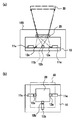
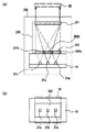
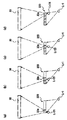
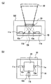
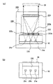
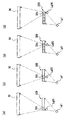
図1は、本実施の形態1にかかる光源装置の構成を示す図であり、図(a)は側面図、図(b)は平面図を示す。 FIG. 1 is a diagram illustrating a configuration of a light source device according to the first embodiment, in which FIG. 1 (a) is a side view and FIG. 1 (b) is a plan view.
図1において、100は本実施の形態1の光源装置で、該光源装置100は、2次元画像表示装置の光源として用いられるものである。この光源装置100は、コヒーレント光源、ここでは赤色光、青色光、緑色光を出射する3つの半導体レーザ(以下、単に「レーザ光源」と称す。)11a〜11cと、該レーザ光源11a〜11cが直接実装される、シリコン基板等であるサブマウント10とを有している。また、光源装置100は、該サブマウント10の上方に設けられ、少なくとも1つのコヒーレント光源、ここでは2つのレーザ光源11a,11b,11cから出射される光を、該3つのコヒーレント光源から出射されるすべての光が同軸ビームになるよう回折する回折部20と、前記サブマウント10上に設けられ、前記3つのレーザ光源11a,11b,11cから出射された光が前記回折部20の同一領域を照射するように、レーザ光源11a,11b,11cからの出射光を反射させるプリズム12a,12b,12cとを有している。そして、前記回折部20の上方には、該回折部20で同軸ビームにされた各光の振幅を空間的に変化させる空間光変調素子30が設けられている。 In FIG. 1,
前記各レーザ光源11a〜11cは端面発光レーザであり、赤色光及び緑色光のレーザ光源11a及び11cは1つの直線上に配置し、青色光のレーザ光源11bは、前記直線と直交する直線上に配置している。また前記プリズム12a,12b,12cの反射面は、図1に示すように、該反射面で反射された前記レーザ光源11a,11b,11cからの出射光の光軸と、レーザ光源11bからの出射光の光軸とが前記回折部20上の一点で交わるように、その反射角度が設定されている。 Each of the
本実施の形態1では、回折部20が1枚の体積ホログラムで構成される。そして、該体積ホログラムには、前記各レーザ光源11a〜11cから出射される各光を回折して同軸ビームにする、複数のグレーティングが多重形成されている。なお、本実施の形態1の体積ホログラムは、該回折部20を通過した各光が、該回折部20の上方に設けられた空間光変調素子30の同一領域を照射するように、前記各光を集光するレンズ作用も有するものである。 In the first embodiment, the
以下、本実施の形態1の回折部20の作製方法を説明する。 Hereinafter, a method for manufacturing the
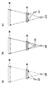
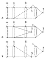
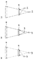
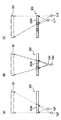
図2は、本実施の形態1の体積ホログラムの作製方法を示す図であり、図2(a)は緑色光のレーザ光源11cから出射される光用のグレーティングの形成方法、図2(b)は青色光のレーザ光源11bから出射される光用のグレーティングの形成方法、図2(c)は赤色光のレーザ光源11aから出射される光用のグレーティングの形成方法をそれぞれ示している。 FIG. 2 is a diagram showing a method for producing a volume hologram according to the first embodiment. FIG. 2A is a method for forming a grating for light emitted from a green laser
例えば、緑色光のレーザ光源11cからの出射光に対応するグレーティングの形成には前記緑色光のレーザ光源11cと同じ波長の光源Lg1,光源Lg2を用いる。このとき、光源Lg1,Lg2は、同一の光源から発生されさらに分割されたレーザ光を発するものである。例えば、一つのレーザ光源からの光を光ファイバ内に導入し、さらにファイバカップラで2本のファイバに分割し、それら2本のファイバの出射端面をLg1,Lg2の位置に配置すればよい。また、光源Lg1は、体積ホログラム20に対する光学的な位置が、図1(a)及び(b)に示すレーザ光源11cと一致するよう配置し、光源Lg2は、回折部20の光出射面を空間光変調素子30の受光面全面に投影する投影中心に配置する。この実施の形態1では、空間光変調素子30は回折部20の真上に位置しているので、光源Lg2は、回折部20の光出射面と垂直な直線上に配置する(図2(a)参照)。そして、該光源Lg1,Lg2からの出射光により前記体積ホログラムを干渉露光する。これにより、該体積ホログラムに干渉縞を記録して、前記レーザ光源11cからの出射光を回折且つ集光するブラッグ(Bragg)グレーティングを形成する。 For example, a light source Lg1 and a light source Lg2 having the same wavelength as that of the
青色光のレーザ光源11bからの出射光に対応するグレーティングの形成には、前記青色光のレーザ光源11bと同じ波長の光源Lb1,光源Lb2を用いる。このとき、光源Lb1,Lb2は、同一の光源から発生されさらに分割されたレーザ光を発するものである。例えば、一つのレーザ光源からの光を光ファイバ内に導入し、さらにファイバカップラで2本のファイバに分割し、それら2本のファイバの出射端面をLb1,Lb2の位置に配置すればよい。また、光源Lb1は、体積ホログラム20に対する光学的な位置が、図1に示すレーザ光源11bと一致するよう配置し、光源Lb2は、前記光源Lg2と同じ位置に配置する(図2(b)参照)。そして、該光源Lb1,Lb2からの出射光により前記体積ホログラムを干渉露光する。これにより、該体積ホログラムに干渉縞をさらに記録して、前記レーザ光源11bからの出射光を集光するブラッググレーティングを形成する。 The light source Lb1 and the light source Lb2 having the same wavelength as that of the blue
赤色光のレーザ光源11aからの出射光に対応するグレーティングの形成には、前記赤色光のレーザ光源11aと同じ波長の光源Lr1,光源Lr2を用いる。このとき、光源Lr1,Lr2は、同一の光源から発生されさらに分割されたレーザ光を発するものである。例えば、一つのレーザ光源からの光を光ファイバ内に導入し、さらにファイバカップラで2本のファイバに分割し、それら2本のファイバの出射端面をLr1,Lr2の位置に配置すればよい。また、光源Lr1は、体積ホログラム20に対する光学的な位置が、図1に示すレーザ光源11aと一致するよう配置し、光源Lr2は、前記光源Lg2と同じ位置に配置する(図2(c)参照)。そして、該光源Lr1,Lr2からの出射光により体積ホログラムを干渉露光する。これにより、該体積ホログラムにさらに干渉縞を記録して、前記レーザ光源11aからの出射光を回折且つ集光するブラッググレーティングを形成する。 The light source Lr1 and the light source Lr2 having the same wavelength as the
なお、前記体積ホログラムの干渉露光は、3つのレーザ光源の各々の出射光に対するグレーティングが1つの体積ホログラムに形成されるよう3回行う必要があり、このため、それぞれの干渉露光は、体積ホログラムを構成する感光性材料が、3回の露光により完全に露光される程度の光強度で行っている。 In addition, the interference exposure of the volume hologram needs to be performed three times so that the grating for the emitted light of each of the three laser light sources is formed in one volume hologram. The photosensitive material which comprises is performed with the light intensity of the grade which is completely exposed by three times of exposure.
次に作用効果について説明する。
前記光源装置100では、サブマウント10上に設けられた赤色光、青色光、緑色光のレーザ光源11a〜11cから光が出射されると、該3つのレーザ光源11a,11b,11cからの出射光は、各出射光の光軸が回折部20上の一点で交わるよう、該サブマウント10上のプリズム12a,12b,12cにより反射される。Next, the function and effect will be described.
In the
そして、各レーザ光源11a,11b,11cからの赤色、青色、緑色のレーザ光は、回折部20において、それぞれの光に応じたグレーティングにより、図1に示すように同軸ビームとなるよう合波されて、前記空間光変調素子30の同じ領域、つまり光受光面を照射する。つまり、プリズムで反射された赤色光、青色光、緑色光のレーザ光源11a,11b,11cからの出射光は、該回折部20を通過する際に、それぞれ回折且つ集光される。これにより、回折部20からの、3つのレーザ光源の出射光を合波した光は、前記空間光変調素子30の一定領域である光受光面を照射する。 Then, the red, blue, and green laser lights from the
以上のように、本実施の形態1によれば、光源装置において、3つのレーザ光源11a〜11cと、レーザ光源11a〜11cからの出射光をこれらが同軸ビームとなるよう合波する、1枚の体積ホログラムからなる回折部20とを備えたので、3つのレーザ光源からの出射光を同軸ビームに変換する光学系を小型化することができ、これにより、携帯電話等のような小型装置に搭載可能な超小型の2次元画像表示装置を実現することができる。 As described above, according to the first embodiment, in the light source device, the three
また、3つの光源を同一サブマウント10上に配置しているので、該3つの光源の放熱を、1枚のサブマウント10の放熱により行うことが可能となり、当該光源装置における光源の放熱処理を容易に行えるという効果もある。 In addition, since the three light sources are arranged on the
また、本実施の形態1においては、3つの光源11a〜11cに端面発光のレーザを用い、青色光のレーザを、緑色光のレーザと赤色光のレーザとを結ぶ直線と直交する直線上に配置しているが、レーザ光源の配置はこれに限るものではない。 In the first embodiment, edge emitting lasers are used for the three
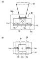
例えば、青色光のレーザに面発光レーザを用い、これを、緑色光のレーザと赤色光のレーザとの間に配置してもよい。図3(a)及び(b)は、このような構成の光源装置100aを示す光源装置100aの側面図及び平面図であり、図3中の、図1(a)及び(b)と同一符号は、光源装置100におけるものと同一のものを示している。 For example, a surface emitting laser may be used as a blue laser, and this may be disposed between a green laser and a red laser. FIGS. 3A and 3B are a side view and a plan view of the
この場合、サブマウント10上に設置するプリズムの数を減らすことができ、当該光源装置100を安価にすることが可能となる。 In this case, the number of prisms installed on the
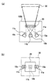
また、本実施の形態1においては、レーザ光源である半導体レーザチップを同一サブマウント10に設けたが、図4(a)及び(b)に示す光源装置100bのように、レーザ光源は、半導体レーザチップを、それぞれ別々のサブマウント10a〜10cにマウントしたものでもよい。なお、図4(a)及び図4(b)は、光源装置100bの側面図及び平面図であり、図4中の、図1(a)及び(b)と同一符号は光源装置100におけるものと同一のものを示している。 In the first embodiment, the semiconductor laser chip that is a laser light source is provided on the
このように3つの光源としての半導体レーザチップを、それぞれ別々のサブマウント10a〜10cにマウントすることにより、該3つの光源のレイアウトの自由度が大きくなり、小型装置における光源装置を設計し易いものとできるという効果がある。 By mounting the semiconductor laser chips as the three light sources on the
さらに、本実施の形態1では、回折部20が集光レンズ作用を有するとして説明したが、回折部20を通過した光が空間光変調素子30の面内に収まるものであれば、回折部20にて各光を集光させる必要はない。この場合、前記体積ホログラムに、レーザ光源11bから出射された光を集光させるグレーティングを形成する必要がなくなるため、前記体積ホログラムの作製工程を減らすことができ、当該装置をより安価に提供することができる。 Furthermore, in the first embodiment, the
また、本実施の形態1においては、コヒーレント光源が3つの場合を例に挙げて説明したが、光源は少なくとも2つ以上であればよい。例えば、コヒーレント光源を4つ以上設ける場合は、赤色光、青色光、緑色光に加えて、青緑色、あるいは黄色などの光を設けるようにすれば、より広い範囲の鮮やかな色を表現できる光源を提供できる。 In the first embodiment, the case where there are three coherent light sources has been described as an example. However, it is sufficient that there are at least two light sources. For example, when four or more coherent light sources are provided, a light source capable of expressing a wider range of vivid colors by providing light such as blue green or yellow in addition to red light, blue light, and green light. Can provide.
また、本実施の形態1では、光源装置は、2次元画像表示装置の光源として用いられるもので、空間光変調素子30は、回折部20からの光の振幅を空間的に変化させるものとしてしているが、この実施の形態の光源装置は、2次元画像表示装置の光源に限るものではなく、2次元画像表示装置以外の、空間光変調素子が回折部20からの光の位相を空間的に変化させるものである装置の光源としても用いることができる。 In the first embodiment, the light source device is used as a light source of a two-dimensional image display device, and the spatial
(実施の形態2)
前記実施の形態1においては、回折部が1枚の回折素子で構成される場合について説明したが、本実施の形態2では、前記回折部が2枚の回折素子で構成される場合について説明する。(Embodiment 2)
In the first embodiment, the case where the diffractive portion is composed of one diffractive element has been described. In the second embodiment, the case where the diffractive portion is composed of two diffractive elements is described. .
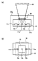
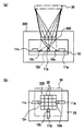
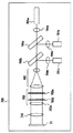
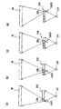
まず、本実施の形態2にかかる光源装置の構成を説明する。図5は、本実施の形態2にかかる光源装置の構成を示す図であり、図5(a)は側面図、図5(b)は平面図を示す。 First, the configuration of the light source device according to the second embodiment will be described. FIG. 5 is a diagram illustrating a configuration of the light source device according to the second embodiment. FIG. 5A is a side view and FIG. 5B is a plan view.
図5において、200は本実施の形態2の光源装置であり、この光源装置200は、シリコン基板等のサブマウント10と、該サブマウント10上に設けられた、赤色光、青色光、緑色光のぞれぞれを出射する3つの半導体レーザ光源(以下、単にレーザ光源と称す。)21a〜21cと、該サブマウント10の上方に設けられ、前記3つのレーザ光源21a〜21cから出射される各光を回折して同軸ビームにする回折部220とを備える。そして、該回折部220の上方には、該回折部220において同軸ビームにされた光の振幅を空間的に変化させる空間光変調素子30が設けられている。 In FIG. 5,
ここで、前記3つのレーザ光源21a〜21cは、レーザチップの上面から発光する面発光レーザであり、これらは前記サブマウント10上で1つの直線に沿って配置される。 Here, the three
そして、本実施の形態2では、回折部220が2枚の体積ホログラム(第1,第2の体積ホログラム)221,222で構成されている。 In the second embodiment, the
前記第2の体積ホログラム222は、前記サブマウント10の上方に設けられ、前記3つのレーザ光源21a〜21cからの各出射光を、さらに上方に設けられた第1の体積ホログラム221上で、該各出射光の光軸が一点で交わるように回折すると共に、該各出射光を、第1の体積ホログラム221の同一領域を照射するように集光するものである。よって、前記第2の体積ホログラム222には、前記各レーザ光源21a〜21cから出射される各光が、第1の体積ホログラム221の同一領域を照射するように、該各光に応じた複数のグレーティング、具体的には、赤色光用のグレーティング222a、青色光用のグレーティング222b、緑色光用のグレーティング222cがそれぞれ形成されている。 The
そして、前記第1の体積ホログラム221は、前記各第2の体積ホログラム222で回折された、各光源からの出射光をさらに回折して、同軸ビームにするものである。よって、前記第1の体積ホログラム221には、前記第2の体積ホログラム222を通過した、各光源からの出射光が同軸ビームになるように回折する複数のグレーティングが多重形成されている。 The
なお、本実施の形態2においては、当該光源装置200をさらに小型化するために、前記光源21a〜21cの配置間隔を狭くして、図5に示すように、該各光源から出射される光が第2の体積ホログラム222上で重なるようにしている。そのため、第2の体積ホログラム222においては、赤色光用,青色光用,緑色光用のグレーティング222a〜222cを部分的に重ねて形成している。 In the second embodiment, in order to further reduce the size of the
以下、本実施の形態2の回折部220の作製方法を説明する。 Hereinafter, a method for manufacturing the
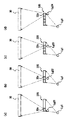
図6は、本実施の形態2の第2の体積ホログラムの作製方法を示す図であり、図6(a)は緑色光用のグレーティング形成方法を、図6(b)は青色光用のグレーティング形成方法を、図6(c)は赤色光用のグレーティング形成方法を示している。また、図7は、本実施の形態2の第1の体積ホログラムの作製方法を示す図であり、図7(a)は緑色光用のグレーティングの形成方法を、図7(b)は青色光用のグレーティングの形成方法を、図7(c)は赤色光用のグレーティングの形成方法を示している。 FIGS. 6A and 6B are diagrams illustrating a second volume hologram manufacturing method according to the second embodiment. FIG. 6A illustrates a method for forming a green light grating, and FIG. 6B illustrates a blue light grating. FIG. 6C shows a forming method, and a grating forming method for red light. FIG. 7 is a diagram showing a first volume hologram manufacturing method according to the second embodiment. FIG. 7A shows a method for forming a grating for green light, and FIG. 7B shows a blue light. FIG. 7C shows a method for forming a grating for red light, and FIG. 7C shows a method for forming a grating for red light.
まず、第2の体積ホログラム222の作製方法を説明する。
第2の体積ホログラム222は、各光源21a〜21cからの出射光の光軸が、第1の体積ホログラム221上で一点で交わるように回折すると共に、該各出射光が第1の体積ホログラム221の同一領域を照射するように集光するものである。First, a method for manufacturing the
The
例えば、緑色光のレーザ光源21cからの出射光に対応するグレーティングの形成には、前記緑色光のレーザ光源21cと同じ波長の光源Lg1,光源Lg2を用いる。このとき光源Lg1,Lg2は、同一の光源から発生されさらに分割されたレーザ光を発するものである。例えば、一つのレーザ光源からの光を光ファイバ内に導入し、さらにファイバカップラで2本のファイバに分割し、それら2本のファイバの出射端面をLg1,Lg2の位置に配置すればよい。ここで、光源Lg1は、体積ホログラム222に対する光学的な位置が、図5(a)及び(b)に示すレーザ光源21cと一致するよう配置し、光源Lg2は、第2の体積ホログラム222における、光源Lg1からの出射光が照射する領域を第1の体積ホログラム221全面に拡大投影する投影中心に配置する(図6(a)参照)。そして、該光源Lg1,Lg2からの出射光により前記第2の体積ホログラム222を干渉露光する。これにより、該第2の体積ホログラム222に干渉縞を記録して、前記レーザ光源21cからの出射光を回折且つ集光するブラッググレーティング222cを形成する。そして、この干渉露光の際には、露光する領域以外の領域は、分割領域に対応した形状のアパーチャを有する遮光マスクにより遮光するようにする。 For example, the light source Lg1 and the light source Lg2 having the same wavelength as the
青色光のレーザ光源21bからの出射光に対するグレーティングの形成には、前記青色光のレーザ光源21bと同じ波長の光源Lb1,光源Lb2を用いる。このとき光源Lb1,Lb2は、同一の光源から発生されさらに分割されたレーザ光を発するものである。例えば、一つのレーザ光源からの光を光ファイバ内に導入し、さらにファイバカップラで2本のファイバに分割し、それら2本のファイバの出射端面をLb1,Lb2の位置に配置すればよい。ここで、光源Lb1は、第2の体積ホログラム222に対する光学的な位置が、図5(a)及び(b)に示すレーザ光源21bと一致するよう配置し、光源Lb2は、第2の体積ホログラム222における、光源Lb1からの出射光が照射する領域を第1の体積ホログラム221全面に拡大投影する投影中心に配置する(図6(b)参照)。そして、該光源Lb1,Lb2からの出射光により前記第2の体積ホログラム222を干渉露光する。これにより、該第2の体積ホログラム222に干渉縞を記録して、前記レーザ光源21bからの出射光を回折且つ集光するブラッググレーティング222bを形成する。そして、この干渉露光の際には、露光する領域以外の領域は、分割領域に対応した形状のアパーチャを有する遮光マスクにより遮光するようにする。 For forming the grating for the light emitted from the blue
赤色光のレーザ光源21aからの出射光に対応するグレーティングの形成には、前記赤色光のレーザ光源21aと同じ波長の光源Lr1,光源Lr2を用いる。このとき光源Lr1,Lr2は、同一の光源から発生されさらに分割されたレーザ光を発するものである。例えば、一つのレーザ光源からの光を光ファイバ内に導入し、さらにファイバカップラで2本のファイバに分割し、それら2本のファイバの出射端面をLr1,Lr2の位置に配置すればよい。ここで、光源Lr1は、体積ホログラム222に対する光学的な位置が、図5(a)及び(b)に示すレーザ光源21aと一致するよう配置し、光源Lr2は、第2の体積ホログラム222における、光源Lr1からの出射光が照射する領域を第1の体積ホログラム221全面に拡大投影する投影中心に配置する。そして、該光源Lr1,Lr2からの出射光により前記第2の体積ホログラム222を干渉露光する。これにより、該第2の体積ホログラム222に干渉縞を記録して、前記レーザ光源21aからの出射光を回折且つ集光するブラッググレーティング222aを形成する。そして、この干渉露光の際には、露光する領域以外の領域は、分割領域に対応した形状のアパーチャを有する遮光マスクにより遮光するようにする。 For the formation of the grating corresponding to the light emitted from the red laser
なお、この実施の形態2では、各光源を、その出射光が第2の体積ホログラム222上で部分的に重なるよう、近接させて配置しているため、作製した第2の体積ホログラム222では、隣接するブラッググレーティング222aとブラッググレーティング222b、隣接するブラッググレーティング222bとブラッググレーティング222cが部分的に重なっている。 In the second embodiment, each light source is arranged close to each other so that the emitted light partially overlaps on the
次に、第1の体積ホログラム221の作製方法を説明する。
第1の体積ホログラム221は、前記第2の体積ホログラム222を通過した各光源21a〜21cからの出射光を、同軸光となるよう回折かつ集光するものである。Next, a method for manufacturing the
The
例えば、緑色光のレーザ光源21cからの出射光に対応するグレーティングの形成には、図7(a)に示すように、レンズLcと、前記緑色光のレーザ光源21cと同じ波長の光源Lg2,光源Lg3とを用いる。このとき光源Lg2,Lg3は、同一の光源から発生されさらに分割されたレーザ光を発するものである。例えば、一つのレーザ光源からの光を光ファイバ内に導入し、さらにファイバカップラで2本のファイバに分割し、それら2本のファイバの出射端面をLg2,Lg3の位置に配置すればよい。ここで、レンズLcは、光源Lg3からの発散光を、これが平行光として第1の体積ホログラムを入射するよう集光するものである。光源Lg2は、第2の体積ホログラム222における、グレーティング222cが形成された領域を、第1の体積ホログラム221全面に拡大投影する投影中心に配置する。そして、該光源Lg2,Lg3からの出射光により、前記第1の体積ホログラム221を干渉露光する。これにより、該第1の体積ホログラム221に干渉縞を記録して、前記レーザ光源21cからの出射光を回折するブラッググレーティングを形成する。 For example, to form a grating corresponding to light emitted from the
このような第1の体積ホログラム221の干渉露光を、図7(b)に示すように、図7(a)に示す光源Lg1,Lg2を、青色光のレーザ光源21bと同じ波長の光源Lb2,光源Lb3に置き換えて行い、さらに、図7(c)に示すように、図7(a)に示す光源Lg1,Lg2を、赤色光のレーザ光源21aと同じ波長の光源Lr2,光源Lr3に置き換えて行う。これにより、第1の体積ホログラム221に、青色光のレーザ光源21bからの出射光、及び赤色光のレーザ光源21aからの出射光それぞれを回折するグレーティングを、緑色光のレーザ光源21cに対するブラッググレーティングに多重して形成する。このとき、光源Lb2は、第2の体積ホログラム222における、グレーティング222bが形成された領域を、第1の体積ホログラム221全面に拡大投影する投影中心に配置し、光源Lr2は、第2の体積ホログラム222における、グレーティング222aが形成された領域を、第1の体積ホログラム221全面に拡大投影する投影中心に配置する。 In such interference exposure of the
なお、前記第1の体積ホログラムの干渉露光は、3つのレーザ光源の各々の出射光に対するグレーティングが1つの体積ホログラムに形成されるよう3回行う必要があるため、それぞれの干渉露光は、体積ホログラムを構成する感光性材料が、3回の露光により完全に露光される程度の光強度で行う。 Note that the interference exposure of the first volume hologram needs to be performed three times so that the grating for the emitted light of each of the three laser light sources is formed in one volume hologram. The light-sensitive material that constitutes the material is subjected to light intensity that can be completely exposed by three exposures.
次に作用効果について説明する。
まず、サブマウント10上に設けられた赤色光、青色光、緑色光のレーザ光源21a〜21cからレーザ光が出射され、該各レーザ光は、回折部220の第2の体積ホログラム222に照射される。Next, the function and effect will be described.
First, laser light is emitted from
そして、各レーザ光源21a〜21cから出射された各光は、前記第2の体積ホログラム222を通過する際に、それぞれ赤色光用,青色光用,緑色光用のグレーティング222a〜222cで回折且つ集光される。これにより、該各光の光軸が前記第1の体積ホログラム221上の一点で交わると共に、該第1の体積ホログラム221の同一領域に照射される。 Then, each light emitted from each
そして、前記各第2の体積ホログラム222で回折且つ集光された各光は、前記第1の体積ホログラム221を通過する際に、図5(a)に示すように、同一光路を伝搬する同軸ビームとなるよう回折されて合波され、前記空間光変調素子30の同一領域を照射する。 Each light diffracted and collected by each
以上のように、本実施の形態2によれば、光源装置において、3つのレーザ光源21a〜21cと、レーザ光源21a〜21cからの出射光をこれらが同軸ビームとなるよう合波する、体積ホログラムからなる回折部220とを備えたので、実施の形態1と同様、携帯電話等のような小型装置に搭載可能な超小型の2次元画像表示装置を実現することができる。 As described above, according to the second embodiment, in the light source device, the volume hologram that combines the three
また、本実施の形態2においては、回折部220を第1及び第2の2つの体積ホログラム221及び222から構成し、第2の体積ホログラム222により3つのレーザ光源からの出射光を、これらの出射光の光軸が前記第1の体積ホログラム221上の一点で交わるよう回折し、第1の体積ホログラム221により、第2の体積ホログラム222からの3つのレーザ光を、空間光変調素子30の同一領域を照射するよう回折するので、各光源から回折部220に入射する光の光軸を、該回折部220上で一致させる必要がなく、面発光レーザなどの、サブマウントに対して垂直方向に光を出射する光源を、前記サブマウント10上に直接配置することができる。この結果、当該光源装置の構成を簡易にでき、その組み立ても容易にできる。このことは当該光源装置のコスト削減につながる。 In the second embodiment, the
また、本実施の形態2では、3つの光源21a〜21cを同一サブマウント10上に設けているので、該3つの光源の放熱を、1枚のサブマウント10を放熱することにより行うことが可能となり、当該光源装置において光源の放熱処理を容易に行えるという効果もある。 In the second embodiment, since the three
なお、本実施の形態2においては、第2の体積ホログラム222は、隣接するグレーティング222a〜222cの境界部分を若干重ねた構成としたが、前記第2の体積ホログラム222は、各光用のグレーティングをその大部分が重なるように多重形成してもよい。このようにすれば装置規模を小さくできる。 In the second embodiment, the
また逆に、前記第2の体積ホログラム222は、各光用のグレーティングを、重ならないよう形成したものでもよい。このようにすれば、光源装置の装置規模は少し大きくなるが、同一サブマウント10上に設置する光源と光源の間に距離をとれるため、光源の放熱を効率よくできるという効果がある。 On the contrary, the
また、本実施の形態2では、第2の体積ホログラム222がレンズ作用を有するとして説明したが、該第2の体積ホログラム222を通過した光の照射領域が第1の体積ホログラム221の面内に収まれば、第2の体積ホログラム222にて各光を集光させる必要はない。この場合、前記第2の体積ホログラム222には、前記2つのレーザ光源21a,21cからの出射光を回折するための異なる2つのグレーティング222a,222cのみを多重形成すればよいため、体積ホログラムに多重するグレーティングの数を減らすことができ、当該装置をさらに安価に提供することができる。 In the second embodiment, the
また、本実施の形態2においては、コヒーレント光源が3つの場合を例に挙げて説明したが、光源は少なくとも2つ以上であればよい。 In the second embodiment, the case where there are three coherent light sources has been described as an example. However, it is sufficient that there are at least two light sources.
(実施の形態3)
本実施の形態3の光源装置は、実施の形態1の光源装置における回折部を、各レーザ光源からの出射光の光強度分布を一様にする光インテグレータの機能を兼ね備えたものとしたものである。(Embodiment 3)
In the light source device according to the third embodiment, the diffractive portion in the light source device according to the first embodiment has a function of an optical integrator that makes the light intensity distribution of the emitted light from each laser light source uniform. is there.
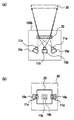
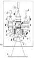
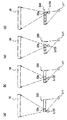
図8は、本実施の形態3にかかる光源装置の構成を示す図であり、図8(a)は側面図、図8(b)は平面図を示す。 FIG. 8 is a diagram illustrating a configuration of the light source device according to the third embodiment, in which FIG. 8A is a side view and FIG. 8B is a plan view.
図8において、300は本実施の形態3にかかる光源装置であり、この光源装置300は、実施の形態1の光源装置100と同様、赤色光,青色光,緑色光のレーザ光源11a,11b,11cと、赤色光,緑色光のレーザ光源11a,11cの出射光を反射するプリズム12a,12b,12cと、これらのレーザ光源及びプリズムを支持するサブマウント10と、プリズム12a,12b,12cで反射されたレーザ光源11a,11b,11cの出射光が通過する回折部320とを有している。ここで、レーザ光源11a〜11c、プリズム12a〜12c、及びサブマウント10は、実施の形態1と同一のものである。 In FIG. 8,
そして、この実施の形態3では、前記回折部320は、入射光を回折するとともに、その光強度分布を均一化するものであり、1枚の体積ホログラムから構成されている。 In the third embodiment, the diffracting
前記体積ホログラム320は、複数の領域に分割されており、ここでは16分割されたものを例に挙げて説明する。 The
前記体積ホログラム320では、16個の分割領域32が縦横4列に並んでいる。そして各分割領域32には、該各領域に入射した前記光源11a〜11cからの出射光を、これが空間光変調素子30の光照射面全体を照らすよう回折するグレーティングが、多重して形成されている。ここで、体積ホログラム320の各領域は入射光の発散角を拡大する凹レンズ作用を有している。 In the
このような16分割された体積ホログラムの各分割領域に入射された各光源からの出射光は、該体積ホログラムの16個の領域それぞれに形成されたグレーティングで回折されて同軸ビームにされると共に、該体積ホログラムの16個の領域それぞれから出力される各光は、前記回折部320の上方に設けられた空間光変調素子30の同一領域を照射する。 The emitted light from each light source incident on each divided region of the volume hologram divided into 16 parts is diffracted by the grating formed in each of the 16 regions of the volume hologram to be a coaxial beam, Each light output from each of the 16 regions of the volume hologram irradiates the same region of the spatial
なお、図8(a)では、図を簡略化するため、主に青色の光源11bから出射された光の光路を表示しているが、赤色,緑色の光源11a,11cから出射された光も同様に、前記回折部320の各分割領域に入射され、該各分割領域に多重形成されたグレーティングにより回折されると共に発散されて、空間光変調素子30の同一領域を照射する。 In FIG. 8A, for the sake of simplicity, the optical path of light emitted from the blue
以下、本実施の形態3の回折部320の作製方法を説明する。
図9は、本実施の形態3の体積ホログラムに、緑色光のレーザ光源から出射された光を回折するグレーティングを形成する方法を示す図であり、図10は、本実施の形態3の体積ホログラムに、青色光のレーザ光源から出射された光を回折するグレーティングを形成する方法を示す図であり、図11は、本実施の形態3の体積ホログラムに、赤色光のレーザ光源から出射された光を回折するグレーティングを形成する方法を示す図である。Hereinafter, a method for manufacturing the
FIG. 9 is a diagram showing a method for forming a grating that diffracts light emitted from a green laser light source in the volume hologram of the third embodiment, and FIG. 10 shows the volume hologram of the third embodiment. FIG. 11 is a diagram showing a method of forming a grating that diffracts light emitted from a blue laser light source. FIG. 11 shows light emitted from a red laser light source in the volume hologram according to the third embodiment. It is a figure which shows the method of forming the grating which diffracts.
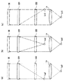
本実施の形態3の体積ホログラム320では、分割された16個の各領域それぞれに個別にグレーティングを形成する必要がある。よって、緑色光のレーザ光源11cからの出射光を回折するグレーティングの形成には、図9(a)〜図9(d)に示すように、前記緑色光のレーザ光源11cと同じ波長の光源Lg1,光源Lg2を用いる。このとき光源Lg1,Lg2は、同一の光源から発生されさらに分割されたレーザ光を発するものである。例えば、一つのレーザ光源からの光を光ファイバ内に導入し、さらにファイバカップラで2本のファイバに分割し、それら2本のファイバの出射端面をLg1,Lg2の位置に配置すればよい。また、これらの光源を用いた干渉露光では、光源Lg1は、体積ホログラム320に対する光学的な位置が図8(a)及び(b)に示すレーザ光源11cと一致する位置に固定し、光源Lg2は、各分割領域32毎にその位置を変える。 In the
例えば、図9(a)〜図9(d)に示すように光源Lg1及びLg2を配置して、干渉露光を4回行うことにより、体積ホログラム320の16個の分割領域のうちの、1列に並ぶ4つの領域にグレーティング32cが形成される。各領域の干渉露光では、光源Lg2は、体積ホログラム320の各領域を空間光変調素子30に拡大投影する投影中心に配置する。従って、図9(a)〜図9(d)に示す4回の干渉露光を、体積ホログラム320における前記分割領域の各列毎に行うことにより、体積ホログラム320の16個の分割領域32すべてに緑色光のレーザ光源11cからの出射光を回折するグレーティング32cが形成される。なお、前記各分割領域32の干渉露光の際には、露光する領域以外の領域は、分割領域に対応した形状のアパーチャを有する遮光マスクにより遮光するようにする。 For example, as shown in FIGS. 9A to 9D, the light sources Lg1 and Lg2 are arranged and interference exposure is performed four times, so that one row of the 16 divided regions of the
また、青色光のレーザ光源11bからの出射光を回折するグレーティングは、図10(a)〜図10(d)に示すように、前記青色光のレーザ光源11bと同じ波長の光源Lb1,光源Lb2を用いた干渉露光を、光源Lb1は、体積ホログラム320に対する光学的な位置が図8(a)及び(b)に示すレーザ光源11cと一致する位置に固定し、光源Lb2は、各分割領域毎にその位置を変えて行うことにより形成する。このとき光源Lb1,Lb2は、同一の光源から発生されさらに分割されたレーザ光を発するものである。例えば、一つのレーザ光源からの光を光ファイバ内に導入し、さらにファイバカップラで2本のファイバに分割し、それら2本のファイバの出射端面をLb1,Lb2の位置に配置すればよい。 In addition, the grating that diffracts the emitted light from the blue
この場合も、図10(a)〜図10(d)に示す4回の干渉露光により、体積ホログラム320の16個の分割領域32のうちの、1列に並ぶ4つの領域に、青色光のレーザ光源からの出射光を回折するグレーティング32bが形成され、この4回の干渉露光を、体積ホログラム320における前記分割領域の各列毎に行うことにより、体積ホログラム320の16個の分割領域32すべてに青色光を回折するグレーティング32bが形成される。また、この場合も、前記各分割領域の干渉露光の際には、露光する領域以外の領域は遮光するようにする。 Also in this case, blue light is emitted to four regions arranged in one row among the 16 divided
同様に、赤色光のレーザ光源11aからの出射光を回折するグレーティングは、図11(a)〜図11(d)に示すように、前記赤色光のレーザ光源11aと同じ波長の光源Lr1,光源Lr2を用いた干渉露光を、光源Lr1は、体積ホログラム320に対する光学的な位置が図8(a)及び(b)に示すレーザ光源11aと一致する位置に固定し、光源Lr2は、各分割領域毎にその位置を変えて行うことにより形成する。このとき光源Lr1,Lr2は、同一の光源から発生されさらに分割されたレーザ光を発するものである。例えば、一つのレーザ光源からの光を光ファイバ内に導入し、さらにファイバカップラで2本のファイバに分割し、それら2本のファイバの出射端面をLr1,Lr2の位置に配置すればよい。 Similarly, as shown in FIGS. 11A to 11D, the grating that diffracts the light emitted from the red laser
この場合も、図11(a)〜図11(d)に示す4回の干渉露光により、体積ホログラム320の16個の分割領域32のうちの、1列に並ぶ4つの領域に、赤色のレーザ光源からの出射光を回折するグレーティング32aが形成され、この4回の干渉露光を、前記分割領域の各列毎に行うことにより、体積ホログラム320の16個の分割領域32すべてに赤色光を回折するグレーティング32aが形成される。また、この場合も、前記各分割領域の干渉露光の際には、露光する領域以外の領域は遮光するようにする。 Also in this case, the red laser is applied to four regions arranged in one row out of the 16 divided
次に作用効果について説明する。
赤色光、青色光、緑色光のレーザ光源11a〜11cから光が出射されると、レーザ光源11a,11b,11cからの出射光は該サブマウント10上に設けられたプリズム12a,12b,12cにより反射され、これらの反射光が回折部320を照射する。このとき、該各レーザ光源11a〜11cから出射された各光は、回折部320上で光軸が一致し、回折部320の同じ領域を照射する。Next, the function and effect will be described.
When light is emitted from the red, blue, and green
そして、赤色光、青色光、緑色光のレーザ光源11a〜11cからの3つの光は、該回折部320を通過する際に、前記回折部320の各分割領域32で、この領域を通過した赤、青、緑の光の光軸が一致し、かつ同一領域、つまり空間光変調素子30の全面を照射するよう回折かつ発散される。これにより、前記空間光変調素子30上には、各色のレーザ光を合波した光強度分布が一様な光が照射される。 Then, when the three lights from the
以上のように、本実施の形態3によれば、回折部320を2次元状に領域分割し、該回折部320の各分割領域に、各光源からの出射光を回折発散するグレーティングを、個々の領域を通過した各光源光が同軸ビームとなって空間光変調素子30の光照射領域全面を照射するよう多重形成したので、3つのレーザ光源からの出射光を同軸ビームに変換する光学系を小型化することができるとともに、前記空間光変調素子30上での各光源光の強度分布も一様にすることができる、超小型の光源装置を提供することができる。 As described above, according to the third embodiment, the
また、従来の光インテグレータを構成するレンズアレイは加工等にコストがかかるが、体積ホログラムは小型で且つ安価な感光性材料(ポリマー)を利用して作製可能なため、本実施の形態3のように、体積ホログラムからなる回折部320が光インテグレータの機能を兼ね備えるようにすれば、装置のコストを削減することができる。 Further, although the lens array constituting the conventional optical integrator is expensive to process, the volume hologram can be manufactured by using a small and inexpensive photosensitive material (polymer), and therefore, as in the third embodiment. In addition, if the
なお、本実施の形態3においては、回折部320が1枚の体積ホログラムで構成されている場合を例に挙げて説明したが、回折部は、実施の形態2のように、2枚の体積ホログラムで構成されるものであってもよい。この場合、図5に示される第1の体積ホログラム221を、本実施の形態3に示したように領域分割した構成にすれば、実施の形態3と同様、空間光変調素子30上での各光源光の光強度分布を一様にすることができる効果が得られる。 In the third embodiment, the case where the
また、本実施の形態3においては、回折部320を16分割した場合を例に挙げたが、回折部の領域分割は16分割に限らず、64分割や128分割、さらにそれ以上の分割が可能であり、また、空間光変調素子の平面形状に応じて、回折部の領域分割を、その分割領域の縦横の配列数が異なるようすることも可能である。 In the third embodiment, the case where the
(実施の形態4)
以下、前記実施の形態1〜3で説明した光源装置を用いた2次元画像表示装置について説明する。
図12は、本実施の形態4における2次元画像表示装置の構成を示す図である。(Embodiment 4)
Hereinafter, a two-dimensional image display device using the light source device described in the first to third embodiments will be described.
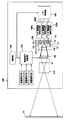
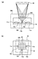
FIG. 12 is a diagram showing a configuration of the two-dimensional image display device according to the fourth embodiment.
図12において、500は本実施の形態4の2次元画像表示装置であり、この2次元画像表示装置500は、赤色光,青色光,緑色光のレーザ光源11a,11b,11cを有する光源装置300と、該光源装置300内の各レーザ光源を駆動させる赤色光用、青色光用、緑色光用のレーザ駆動部550a〜550cと、該各レーザ駆動部550a〜550cの駆動を切り替えるレーザ切替部540と、外部から入力される赤色映像信号、青色映像信号、緑色映像信号を切り替えて空間光変調素子30に出力する映像信号切替部530と、RGBの各画像を順次表示するように制御信号を出力して、前記レーザ切替部540及び映像信号切替部530を制御する制御部520と、前記光源装置300より出力された各レーザ光を平行光束に近い集光光速にするフィールドレンズ560と、前記空間光変調素子30からの出射光を受光し、スクリーン51上に投写する投射レンズ510とを有している。ここで、前記光源装置300は、前記実施の形態3のものと同一のものである。 In FIG. 12,
次に、前述のように構成された2次元画像表示装置500の動作について説明する。
まず、映像信号切替部530は、制御部520から出力される制御信号に応じて、入力された赤色映像信号、青色映像信号、緑色映像信号を順次切り替えて空間光変調素子30に出力する。Next, the operation of the two-dimensional
First, the video
また、レーザ切替部540は、前記制御部520からの制御信号に応じて、赤色光用、青色光用、緑色光用のレーザ駆動部550a〜550cを駆動させて、赤色、青色、緑色のレーザ光源11a〜11cを順次点灯させる。 The
これにより、各色のレーザ光源での発光と、前記空間光変調素子30による各色の画像の形成とが同期して行われる。具体的には、赤色光用レーザ光源11aの発光状態では、前記空間光変調素子30に赤色映像信号が供給されて赤色光の変調が行われ、青色光用レーザ光源11bの発光状態では、前記空間光変調素子30に青色映像信号が供給されて青色光の変調が行われ、緑色光用レーザ光源11cの発光状態では、前記空間光変調素子30に緑色映像信号が供給されて緑色光の変調が行われる。 Thereby, the light emission by the laser light source of each color and the formation of the image of each color by the spatial
そして、このような空間光変調素子30による各色の光の変調により形成された画像は、投射レンズ510によりスクリーン51上に投写される。 An image formed by modulating the light of each color by the spatial
なお、動画を表示する場合、短時間に多くのフレーム数の画像、例えば毎秒30フレームの画像を表示する必要があるが、当該装置500にてこれを実現するためには、毎秒30フレームで表示する画像の1フレームの画像表示中に、各光源11a〜11cを数回ずつ発光させるよう前記制御部520で制御するようにすれば、人間の目で観察したときに各色の画像は分離できなくなるため、ユーザはフルカラーの自然な動画像を観察することができる。 When displaying a moving image, it is necessary to display an image with a large number of frames in a short time, for example, an image of 30 frames per second. In order to realize this in the
以上のように、本実施の形態4によれば、2次元画像表示装置500の光源装置を、3つのレーザ光源11a〜11cと、レーザ光源11a〜11cからの出射光をこれらが同軸ビームとなるよう合波する、体積ホログラムからなる回折部320とを有するものとしたので、3つのレーザ光源からの出射光を同軸ビームに変換する光学系を小型化することができ、これにより2次元画像表示装置を小型化することが可能となる。 As described above, according to the fourth embodiment, the light source device of the two-dimensional
また、本実施の形態4によれば、当該光源装置300の回折部320が、光インテグレータの機能を兼ね備えているため、従来光強度分布の均一化に必要であったフライアイレンズからなる光インテグレータを用いなくても、光源装置の出力光は強度分布の均一なものとなる。これにより、光源光の強度分布が一様である2次元画像表示装置をより小型化できると共に、当該2次元画像表示装置の構成部品数も削減でき、組み立てが簡単で、且つ安価な2次元画像表示装置を実現することができる。 Further, according to the fourth embodiment, since the
本発明の光源装置及び2次元画像表示装置は、小型の画像投影装置、携帯型情報端末、あるいはノート型パーソナルコンピュータ等に使用するものとして有用である。 The light source device and the two-dimensional image display device of the present invention are useful for use in a small image projection device, a portable information terminal, a notebook personal computer, or the like.
本発明は、光源装置及び2次元画像表示装置に関し、特に2次元画像表示装置の小型化を実現する光源装置、及び該光源装置を用いた小型の2次元画像表示装置に関する。 The present invention relates to a light source device and a two-dimensional image display device, and more particularly to a light source device that realizes miniaturization of a two-dimensional image display device and a small two-dimensional image display device using the light source device.
近年、鮮やかな色表現が可能な2次元画像表示装置(レーザディスプレイ装置)が注目されている。これは、赤色、緑色、青色の3つのコヒーレント光源(例えば、レーザ光源)を用いたもので、例えば図13のような構成をとる。 In recent years, a two-dimensional image display device (laser display device) capable of vivid color expression has attracted attention. This uses three coherent light sources (for example, laser light sources) of red, green, and blue, and has a configuration as shown in FIG. 13, for example.
図13において、600は従来のレーザ光源を用いた2次元画像表示装置である。この2次元画像表示装置600は、赤色、緑色、青色レーザ光源601a,601b,601cと、ビームエキスパンダ602a,602b,602cと、光インテグレータ603a,603b,603cと、ミラー604a,604cと、拡散板606a,606b,606cと、拡散板移動手段605a,605b,605cと、空間光変調素子607a,607b,607cと、フィールドレンズ608a,608b,608cと、ダイクロイックプリズム609と、投写レンズ610とを有している。
In FIG. 13,
この2次元画像表示装置600では、赤色、緑色、青色レーザ光源601a,601b,601cからの光がそれぞれビームエキスパンダ602a,602b,602cで拡大され、光インテグレータ603a,603b,603cを通過する。光インテグレータ603a,603cを通過した赤色光及び青色光はミラー604a,604cにより光路が90度曲げられて、光インテグレータ603bを通過した緑色光は、光路が折り曲げられることなく、それぞれ、フィールドレンズ608a,608b,608c、拡散板606a,606b,606cを介して空間光変調素子607a,607b,607cを照射する。3種のレーザ光源601a,601b,601cからの光は、光インテグレータ603a,603b,603cを通過することで空間光変調素子607a,607b,607c上での照度分布が一定になる。この空間光変調素子607a,607b,607cでそれぞれ独立に変調された光は、ダイクロイックプリズム609で合波されて、同一光路を伝搬する同軸ビームとなり、さらに投写レンズ610にて拡大投射されてスクリーン61上に結像される。その際、レーザ光干渉性が高いため、スクリーン61に投写された像にはスペックルノイズが重畳される。これを防ぐために拡散板606a,606b,606cを拡散板移動手段605a,605b,605cにて揺動し、スペックルノイズを時間平均するようにしている。
In the two-dimensional
しかし、図13に示すような従来の2次元画像表示装置600では、3種のレーザ光源601a〜601cからの光を拡大して光強度分布を一様にするために、ビームエキスパンダ及び光インテグレータが各々3つ必要となる。さらに、前記3種のレーザ光源からの光を互いに平行で同一光路を伝搬する同軸ビームにするために、当該装置内に多くのレンズやミラーを配置することも必要となる。このため、従来の2次元画像表示装置は、装置全体が大規模となってしまうという課題があった。
However, in the conventional two-dimensional
この課題を解決するために、2次元画像表示装置の光学系を、例えば、図14に示すように、まず赤色、緑色、青色の3色のレーザ光源から出射された光をダイクロイックミラーを用いて混合した後、ビームエキスパンダ、光インテグレータを通過させる構成にすることが考えられる。 In order to solve this problem, the optical system of the two-dimensional image display device, for example, as shown in FIG. 14, first uses a dichroic mirror to emit light emitted from laser light sources of three colors of red, green, and blue. After mixing, it can be considered that the beam expander and the optical integrator are passed.
図14において、700は、従来のレーザ光源を用いた2次元画像表示装置である。この2次元画像表示装置700は、赤色、緑色、青色レーザ光源701a,701b,701cと、コリメートレンズ704a,704b、704cと、第1,第2のダイクロイックミラー705a,705bと、ビームエキスパンダ702と、光インテグレータ703と、投射レンズ710と、液晶パネル71とを有している。
In FIG. 14,
ここでダイクロイックミラーは、ガラス基板上に多層膜を積層して、波長によって透過率を異ならせるものである。図14に示す2次元画像表示装置700の第1のダイクロイックミラー705aは、580nm程度の波長を境に、該波長より短波長の光を反射して長波長の光のみを通過させるもの、第2のダイクロイックミラー705bは、490nm程度の波長を境に、該波長より短波長の光を反射して長波長の光のみを通過させるものである。
Here, the dichroic mirror is formed by laminating a multilayer film on a glass substrate and changing the transmittance depending on the wavelength. The first
このような従来のレーザ光源を用いた2次元画像表示装置700では、まず、赤色、緑色、青色レーザ光源701a,701b,701cからの出射光を、コリメートレンズ704a,704b、704cでコリメートし、該コリメートした光を、第1,第2のダイクロイックミラー705a,705bによって、互いに平行で同一光路を伝搬する同軸ビームとした後、ビームエキスパンダ702に入射させる。そして、該ビームエキスパンダ702に入射した光は、ビームエキスパンダ702において拡大された後、光インテグレータ703を通過する。前記光インテグレータ703は、長方形のエレメントレンズが2次元状にアレイ化された2枚のフライアイレンズ703a及び703bと、コリメートレンズ703cとを有しており、1枚目のフライアイレンズ703aの各エレメントレンズ上の光が、2枚目のフライアイレンズ703bによって2次元空間光変調素子上に結像され、これによって、各エレメントレンズ上での光強度分布が2次元空間光変調素子上で多重化されることとなり、2次元空間光変調素子上での光強度分布が一様になるものである。
In the two-dimensional
そして、前記光インテグレータ703を通過して光強度分布が一様にされた光は、投射レンズ710により液晶パネル71上に結像する。
このように、図13のように、各レーザ光源601a〜601cから出射された光をビームエキスパンダ602a〜602cで拡大し、光インテグレータ603a〜603bでその光強度分布を一様にした後、ダイクロイックプリズム609で合波して同軸ビームにするより、図14のように、各レーザ光源701a〜701cから出射された光を、まず第1,第2のダイクロイックミラー705a,705bで合波して同軸ビームにした後、ビームエキスパンダ702で拡大して光インテグレータ703でその光強度分布を一様した方が、2次元画像表示装置全体の装置規模を縮小することができる。
As shown in FIG. 13, the light emitted from each of the
しかし、従来の2次元画像表示装置は、その光学系全体を図14に示すように構成しても、携帯電話等のような小型装置に搭載するには、まだ部品数も多いし、装置規模も大きいという課題がある。 However, even if the conventional two-dimensional image display apparatus is configured as shown in FIG. 14, the number of parts is still large for mounting on a small apparatus such as a mobile phone, and the scale of the apparatus is large. There is also a problem that it is big.
本発明は、前記課題を解決するためになされたものであり、小型装置に搭載可能な超小型の光源装置、及び該光源装置を用いた小型の2次元画像表示装置を提供することを目的とする。 The present invention has been made to solve the above-described problems, and an object thereof is to provide an ultra-small light source device that can be mounted on a small device and a small two-dimensional image display device using the light source device. To do.
前記課題を解決するために、本発明の光源装置は、少なくとも2つのコヒーレント光源と、該少なくとも2つのコヒーレント光源から出射された各光が同一光路を伝搬するよう、少なくとも1つのコヒーレント光源から出射された光を回折する回折部と、を具備するものである。 In order to solve the above-mentioned problems, the light source device of the present invention emits at least two coherent light sources and at least one coherent light source so that each of the lights emitted from the at least two coherent light sources propagates in the same optical path. A diffractive portion that diffracts the reflected light.
これにより、回折部において複数のコヒーレント光源から出射された各光を簡易に合波させることができ、光源装置を超小型化できる。 Thereby, each light radiate | emitted from the several coherent light source in a diffraction part can be combined easily, and a light source device can be reduced in size.
また、本発明の光源装置は、前記少なくとも2つのコヒーレント光源から出射された各光の伝搬光路は、前記回折部上で互いに重なり合うものである。
これにより、当該光源装置をさらに小型化することが可能となる。
In the light source device of the present invention, the propagation optical paths of the lights emitted from the at least two coherent light sources overlap each other on the diffraction part.
As a result, the light source device can be further reduced in size.
また、本発明の光源装置は、前記少なくとも2つのコヒーレント光源から出射された各光の伝搬光路の中心軸は、前記回折部上の一点で交わるものである。
これにより、当該光源装置をさらに小型化することが可能となる。
In the light source device of the present invention, the central axis of the propagation optical path of each light emitted from the at least two coherent light sources intersects at one point on the diffraction unit.
As a result, the light source device can be further reduced in size.
また、本発明の光源装置は、前記少なくとも2つのコヒーレント光源は、同一のサブマウント上に設置されるものである。 In the light source device of the present invention, the at least two coherent light sources are installed on the same submount.
これにより、1枚のサブマウントの放熱により、3つの光源の放熱を行うことができ、当該光源装置における光源の放熱を簡単な構成により実現できるという効果もある。 Thereby, the heat radiation of the three light sources can be performed by the heat radiation of one submount, and the heat radiation of the light source in the light source device can be realized with a simple configuration.
また、本発明の光源装置は、前記コヒーレント光源は、赤色光を発光するコヒーレント光源と、緑色光を発光するコヒーレント光源と、青色光を発光するコヒーレント光源であるものである。
これにより、RGBの光を点灯する小型の光源装置を提供することができる。
In the light source device of the present invention, the coherent light source is a coherent light source that emits red light, a coherent light source that emits green light, and a coherent light source that emits blue light.
Thereby, the small light source device which lights up the RGB light can be provided.
また、本発明の光源装置は、前記回折部を、前記コヒーレント光源のうち、少なくとも1つのコヒーレント光源から出射される光が、該回折部で回折せずに通過するものとしたものである。 In the light source device of the present invention, light emitted from at least one coherent light source among the coherent light sources passes through the diffraction unit without being diffracted by the diffraction unit.
これにより、回折部の作製工程を削減できるため、当該光源装置をより安価に提供できる。 Thereby, since the manufacturing process of a diffraction part can be reduced, the said light source device can be provided more cheaply.
また、本発明の光源装置は、前記回折部は、1つの回折素子で構成され、前記回折素子は、該少なくとも2つのコヒーレント光源から出射された各光が同一光路を伝搬するよう、少なくとも1つのコヒーレント光源から出射された光を回折するものである。
これにより、前記回折部をコンパクトにして、当該光源装置を超小型化することが可能となる。
Further, in the light source device of the present invention, the diffractive portion includes one diffractive element, and the diffractive element includes at least one light so that each light emitted from the at least two coherent light sources propagates in the same optical path. It diffracts light emitted from a coherent light source.
As a result, the diffractive portion can be made compact, and the light source device can be miniaturized.
さらに、本発明の光源装置は、前記回折素子は、レンズ作用を更に備えるものである。 Furthermore, in the light source device of the present invention, the diffraction element further includes a lens action.
これにより、前記複数のコヒーレント光源から出射される各光が、前記回折素子の上方の同一平面領域を照射することができる。 Thereby, each light radiate | emitted from these coherent light sources can irradiate the same plane area | region above the said diffraction element.
また、本発明の光源装置は、前記回折部を、受光した少なくとも2つの光が同一光路を伝搬するよう、該受光した少なくとも1つの光を回折する第1の回折素子と、前記少なくとも2つのコヒーレント光源のうちの、少なくとも1つのコヒーレント光源から出射された光を、該各コヒーレント光源からの光の伝搬光路の中心軸が前記第1の回折素子上の一点で交わるように回折する第2の回折素子と、から構成したものである。 In the light source device of the present invention, the first diffraction element that diffracts at least one received light and the at least two coherent so that at least two received light propagates through the same optical path. Second diffraction that diffracts light emitted from at least one coherent light source of the light sources so that a central axis of a propagation path of light from each coherent light source intersects at one point on the first diffraction element It is comprised from the element.
これにより、前記回折部において前記複数のコヒーレント光源からの各光を簡易に同軸ビームにして合波できる小型の光源装置を、より安価に提供できる。 Accordingly, a small light source device that can easily combine the light beams from the plurality of coherent light sources into coaxial beams in the diffraction unit can be provided at a lower cost.
さらに、本発明の光源装置は、前記第2の回折素子は、レンズ作用を更に備え、前記第2の回折素子は、前記少なくとも2つのコヒーレント光源から出射される各光を集光して、該第2の回折素子にて回折された各光が、前記第1の回折素子の同一領域を照射するようにするものである。 Furthermore, in the light source device of the present invention, the second diffractive element further includes a lens action, and the second diffractive element condenses each light emitted from the at least two coherent light sources, and Each light diffracted by the second diffractive element irradiates the same region of the first diffractive element.
これにより、前記複数のコヒーレント光源から出射される各光が、前記第2の回折素子の上方に設けられた第1の回折素子の同一領域を照射するようにすることができる。 Thereby, each light radiate | emitted from these coherent light sources can irradiate the same area | region of the 1st diffraction element provided above the said 2nd diffraction element.
さらに、本発明の光源装置は、前記回折素子は、体積ホログラムであり、該体積ホログラムは、前記少なくとも2つのコヒーレント光源から出射される各光を受光して、該各光の伝搬方向を変化させる複数のグレーティングが多重化されているものである。 Further, in the light source device of the present invention, the diffraction element is a volume hologram, and the volume hologram receives each light emitted from the at least two coherent light sources and changes a propagation direction of each light. A plurality of gratings are multiplexed.
これにより、回折部において前記複数のコヒーレント光源からの各光を簡易に同軸ビームにして合波する光源装置の超小型化を実現することができる。 As a result, it is possible to realize a miniaturization of the light source device that easily combines the light beams from the plurality of coherent light sources into a coaxial beam in the diffraction unit.
さらに、本発明の光源装置は、前記回折素子は、領域分割されており、該回折素子の各分割領域において回折された各光が、同一平面領域を照射するものである。 Further, in the light source device of the present invention, the diffraction element is divided into regions, and each light diffracted in each divided region of the diffraction element irradiates the same plane region.
これにより、前記回折素子に光インテグレータの機能を兼ね備えさせることが可能となり、前記空間に照射される光の強度分布を均等にすることが可能となる。 As a result, the diffraction element can be provided with the function of an optical integrator, and the intensity distribution of the light applied to the space can be made uniform.
さらに、本発明の光源装置は、前記回折素子は、格子状に領域分割されている、ものである。
これにより、前記空間に照射される光の強度分布をさらに均等にすることが可能となる。
Furthermore, in the light source device of the present invention, the diffraction element is divided into regions in a lattice shape.
Thereby, the intensity distribution of the light irradiated to the space can be made more uniform.
本発明の2次元画像表示装置は、少なくとも2つのコヒーレント光源と、該少なくとも2つのコヒーレント光源から出射された各光が同一光路を伝搬するよう、少なくとも1つのコヒーレント光源から出射された光を回折する回折部と、該回折部上の空間に設けられ、該回折部で回折され同軸ビームにされた各光を受光する2次元空間光変調素子と、を具備するものである。 The two-dimensional image display apparatus according to the present invention diffracts light emitted from at least one coherent light source so that at least two coherent light sources and each light emitted from the at least two coherent light sources propagates in the same optical path. A diffractive portion; and a two-dimensional spatial light modulation element that is provided in a space on the diffractive portion and receives each light diffracted by the diffractive portion into a coaxial beam.
これにより、光源装置から出射された光を表示する2次元画像表示装置を小型化することができる。 Thereby, the two-dimensional image display apparatus which displays the light radiate | emitted from the light source device can be reduced in size.
また、本発明の2次元画像表示装置は、前記少なくとも2つのコヒーレント光源の動作を制御する制御部を備え、前記少なくとも2つのコヒーレント光源は、赤色光を発光するコヒーレント光源と、緑色光を発光するコヒーレント光源と、青色光を発光するコヒーレント光源であり、前記制御部は、該3つのコヒーレント光源を、時間分割されて順次光を出射するように制御するものである。 The two-dimensional image display device of the present invention includes a control unit that controls operations of the at least two coherent light sources, and the at least two coherent light sources emit a red light and a green light. A coherent light source and a coherent light source that emits blue light, and the control unit controls the three coherent light sources so as to emit light sequentially in a time-division manner.
これにより、当該2次元画像表示装置において動画像も表示可能となる。 Thereby, a moving image can also be displayed on the two-dimensional image display device.
本発明の光源装置によれば、複数のコヒーレント光源を有する光源装置において、前記コヒーレント光源から出射された各光を同一光路を伝搬するように回折する回折部を備えたので、前記複数のコヒーレント光源からの各光を、同軸ビームとなるよう合波する光学系をコンパクトにすることができ、超小型の光源装置を提供することが可能となる。 According to the light source device of the present invention, in the light source device having a plurality of coherent light sources, the diffraction unit that diffracts each light emitted from the coherent light source so as to propagate in the same optical path is provided. It is possible to make the optical system that combines the light from each of the light beams into a coaxial beam compact, and to provide an ultra-small light source device.
また、本発明の光源装置によれば、前記複数のコヒーレント光源のうち、少なくとも1つのコヒーレント光源から出射される光は、前記回折部で回折せず通過するようにしたので、前記回折部に多重化するグレーティングの数を少なくすることができ、当該光源装置を安価に構成することが可能となる。 Also, according to the light source device of the present invention, light emitted from at least one coherent light source among the plurality of coherent light sources passes through without being diffracted by the diffractive part. The number of gratings to be reduced can be reduced, and the light source device can be configured at low cost.
また、本発明の光源装置によれば、回折部を第1及び第2の2つの回折格子により構成し、第2の回折格子を、複数のコヒーレント光源からの光を、これらの光が第1の回折素子の同一領域に照射するよう回折するものとし、第1の回折格子を、前記第2の回折素子を通過した各光を同軸ビームになるよう回折するものとしたので、複数の光源からの光を簡易に同軸ビームになるよう合波することができる小型の光源装置を提供することが可能となる。 Further, according to the light source device of the present invention, the diffractive portion is constituted by the first and second diffraction gratings, the second diffraction grating is made up of light from a plurality of coherent light sources, and these lights are the first. And the first diffraction grating diffracts each light that has passed through the second diffraction element into a coaxial beam. Therefore, it is possible to provide a small light source device that can multiplex the light into a coaxial beam.
また、本発明の光源装置によれば、前記複数のコヒーレント光源を同一サブマウント上に設けるようにしたので、複数の光源の放熱を1枚のサブマウントの放熱により行うことができ、光源装置における放熱処理を容易に行える効果もある。 Further, according to the light source device of the present invention, since the plurality of coherent light sources are provided on the same submount, the heat radiation of the plurality of light sources can be performed by the heat radiation of one submount. There is also an effect that heat treatment can be easily performed.
また、本発明の光源装置によれば、前記回折部を領域分割し、該回折部の各分割領域を、複数のグレーティングが多重形成され、且つ凹レンズ作用を備えたものとしたので、前記複数のコヒーレント光源から出射された各光を簡易に同軸ビームにして合波できることに加え、該回折部から出射される光の強度分布を一様にすることができる。さらに、該回折部から出射される光の強度分布を一様にする光インテグレータを有する回折部は、従来のレンズアレイに比べ、小型で且つ材料に安価なものを利用可能なため、光源装置を安価に実現することができる。 Further, according to the light source device of the present invention, the diffractive portion is divided into regions, and each divided region of the diffractive portion is provided with a plurality of gratings and having a concave lens action. In addition to being able to easily combine the light emitted from the coherent light source into a coaxial beam, the intensity distribution of the light emitted from the diffraction unit can be made uniform. Furthermore, since the diffractive part having an optical integrator that uniformizes the intensity distribution of the light emitted from the diffractive part is smaller and cheaper than the conventional lens array, a light source device can be used. It can be realized at low cost.
また、本発明の2次元画像表示装置によれば、光源装置を、回折素子を用いた小型化されたものとしたので、2次元画像表示装置を小型化することが可能となる。 Further, according to the two-dimensional image display device of the present invention, since the light source device is miniaturized using a diffraction element, the two-dimensional image display device can be miniaturized.
さらに、本発明の2次元画像表示装置によれば、前記光源装置の回折部が、光インテグレータの機能を兼ね備えているため、従来は光強度分布の均一化に必要であったフライアイレンズを用いなくても、光源装置の出力光は強度分布の均一なものとなり、光源光の強度分布が一様である2次元画像表示装置をより小型化できると共に、当該2次元画像表示装置の構成部品数も削減できる。この結果、光源光の強度分布が一様な2次元画像表示装置を、組み立てが簡単で、且つ安価なものとできる。 Furthermore, according to the two-dimensional image display device of the present invention, since the diffractive portion of the light source device also has the function of an optical integrator, a fly-eye lens that has been conventionally required for uniformizing the light intensity distribution is used. Even if not, the output light of the light source device has a uniform intensity distribution, and the two-dimensional image display device having a uniform intensity distribution of the light source light can be further miniaturized and the number of components of the two-dimensional image display device can be reduced. Can also be reduced. As a result, a two-dimensional image display device having a uniform intensity distribution of light source light can be easily assembled and inexpensive.
以下、本発明の各実施の形態について説明する。
(実施の形態1)
本実施の形態1では、1枚の回折素子で、赤色、青色、緑色の光を出射する3つのコヒーレント光源から出射される光を同軸ビームになるよう回折して、該各光を合波する光源装置について説明する。なお、以下の説明において、「同軸ビーム」とは、同一光路を伝搬する光を意味するもの、「光軸」とは、光伝搬路の中心軸を意味するものとする。
Hereinafter, each embodiment of the present invention will be described.
(Embodiment 1)
In the first embodiment, a single diffractive element diffracts light emitted from three coherent light sources that emit red, blue, and green light into coaxial beams, and multiplexes the lights. The light source device will be described. In the following description, “coaxial beam” means light propagating in the same optical path, and “optical axis” means the central axis of the optical propagation path.
図1は、本実施の形態1にかかる光源装置の構成を示す図であり、図(a)は側面図、図(b)は平面図を示す。 FIG. 1 is a diagram illustrating a configuration of a light source device according to the first embodiment, in which FIG. 1 (a) is a side view and FIG. 1 (b) is a plan view.
図1において、100は本実施の形態1の光源装置で、該光源装置100は、2次元画像表示装置の光源として用いられるものである。この光源装置100は、コヒーレント光源、ここでは赤色光、青色光、緑色光を出射する3つの半導体レーザ(以下、単に「レーザ光源」と称す。)11a〜11cと、該レーザ光源11a〜11cが直接実装される、シリコン基板等であるサブマウント10とを有している。また、光源装置100は、該サブマウント10の上方に設けられ、少なくとも1つのコヒーレント光源、ここでは3つのレーザ光源11a,11b,11cから出射される光を、該3つのコヒーレント光源から出射されるすべての光が同軸ビームになるよう回折する回折部20と、前記サブマウント10上に設けられ、前記3つのレーザ光源11a,11b,11cから出射された光が前記回折部20の同一領域を照射するように、レーザ光源11a,11b,11cからの出射光を反射させるプリズム12a,12b,12cとを有している。そして、前記回折部20の上方には、該回折部20で同軸ビームにされた各光の振幅を空間的に変化させる空間光変調素子30が設けられている。
In FIG. 1,
前記各レーザ光源11a〜11cは端面発光レーザであり、赤色光及び緑色光のレーザ光源11a及び11cは1つの直線上に配置し、青色光のレーザ光源11bは、前記直線と直交する直線上に配置している。また前記プリズム12a,12b,12cの反射面は、図1に示すように、該反射面で反射された前記レーザ光源11a,11b,11cからの出射光の光軸と、レーザ光源11bからの出射光の光軸とが前記回折部20上の一点で交わるように、その反射角度が設定されている。
Each of the
本実施の形態1では、回折部20が1枚の体積ホログラムで構成される。そして、該体積ホログラムには、前記各レーザ光源11a〜11cから出射される各光を回折して同軸ビームにする、複数のグレーティングが多重形成されている。なお、本実施の形態1の体積ホログラムは、該回折部20を通過した各光が、該回折部20の上方に設けられた空間光変調素子30の同一領域を照射するように、前記各光を集光するレンズ作用も有するものである。
In the first embodiment, the
以下、本実施の形態1の回折部20の作製方法を説明する。
図2は、本実施の形態1の体積ホログラムの作製方法を示す図であり、図2(a)は緑色光のレーザ光源11cから出射される光用のグレーティングの形成方法、図2(b)は青色光のレーザ光源11bから出射される光用のグレーティングの形成方法、図2(c)は赤色光のレーザ光源11aから出射される光用のグレーティングの形成方法をそれぞれ示している。
Hereinafter, a method for manufacturing the
FIG. 2 is a diagram showing a method for producing a volume hologram according to the first embodiment. FIG. 2A is a method for forming a grating for light emitted from a green laser
例えば、緑色光のレーザ光源11cからの出射光に対応するグレーティングの形成には前記緑色光のレーザ光源11cと同じ波長の光源Lg1,光源Lg2を用いる。このとき、光源Lg1,Lg2は、同一の光源から発生されさらに分割されたレーザ光を発するものである。例えば、一つのレーザ光源からの光を光ファイバ内に導入し、さらにファイバカップラで2本のファイバに分割し、それら2本のファイバの出射端面をLg1,Lg2の位置に配置すればよい。また、光源Lg1は、体積ホログラム20に対する光学的な位置が、図1(a)及び(b)に示すレーザ光源11cと一致するよう配置し、光源Lg2は、回折部20の光出射面を空間光変調素子30の受光面全面に投影する投影中心に配置する。この実施の形態1では、空間光変調素子30は回折部20の真上に位置しているので、光源Lg2は、回折部20の光出射面と垂直な直線上に配置する(図2(a)参照)。そして、該光源Lg1,Lg2からの出射光により前記体積ホログラムを干渉露光する。これにより、該体積ホログラムに干渉縞を記録して、前記レーザ光源11cからの出射光を回折且つ集光するブラッグ(Bragg)グレーティングを形成する。
For example, a light source Lg1 and a light source Lg2 having the same wavelength as that of the
青色光のレーザ光源11bからの出射光に対応するグレーティングの形成には、前記青色光のレーザ光源11bと同じ波長の光源Lb1,光源Lb2を用いる。このとき、光源Lb1,Lb2は、同一の光源から発生されさらに分割されたレーザ光を発するものである。例えば、一つのレーザ光源からの光を光ファイバ内に導入し、さらにファイバカップラで2本のファイバに分割し、それら2本のファイバの出射端面をLb1,Lb2の位置に配置すればよい。また、光源Lb1は、体積ホログラム20に対する光学的な位置が、図1に示すレーザ光源11bと一致するよう配置し、光源Lb2は、前記光源Lg2と同じ位置に配置する(図2(b)参照)。そして、該光源Lb1,Lb2からの出射光により前記体積ホログラムを干渉露光する。これにより、該体積ホログラムに干渉縞をさらに記録して、前記レーザ光源11bからの出射光を集光するブラッググレーティングを形成する。
The light source Lb1 and the light source Lb2 having the same wavelength as that of the blue
赤色光のレーザ光源11aからの出射光に対応するグレーティングの形成には、前記赤色光のレーザ光源11aと同じ波長の光源Lr1,光源Lr2を用いる。このとき、光源Lr1,Lr2は、同一の光源から発生されさらに分割されたレーザ光を発するものである。例えば、一つのレーザ光源からの光を光ファイバ内に導入し、さらにファイバカップラで2本のファイバに分割し、それら2本のファイバの出射端面をLr1,Lr2の位置に配置すればよい。また、光源Lr1は、体積ホログラム20に対する光学的な位置が、図1に示すレーザ光源11aと一致するよう配置し、光源Lr2は、前記光源Lg2と同じ位置に配置する(図2(c)参照)。そして、該光源Lr1,Lr2からの出射光により体積ホログラムを干渉露光する。これにより、該体積ホログラムにさらに干渉縞を記録して、前記レーザ光源11aからの出射光を回折且つ集光するブラッググレーティングを形成する。
The light source Lr1 and the light source Lr2 having the same wavelength as the
なお、前記体積ホログラムの干渉露光は、3つのレーザ光源の各々の出射光に対するグレーティングが1つの体積ホログラムに形成されるよう3回行う必要があり、このため、それぞれの干渉露光は、体積ホログラムを構成する感光性材料が、3回の露光により完全に露光される程度の光強度で行っている。 In addition, the interference exposure of the volume hologram needs to be performed three times so that the grating for the emitted light of each of the three laser light sources is formed in one volume hologram. The photosensitive material which comprises is performed with the light intensity of the grade which is completely exposed by three times of exposure.
次に作用効果について説明する。
前記光源装置100では、サブマウント10上に設けられた赤色光、青色光、緑色光のレーザ光源11a〜11cから光が出射されると、該3つのレーザ光源11a,11b,11cからの出射光は、各出射光の光軸が回折部20上の一点で交わるよう、該サブマウント10上のプリズム12a,12b,12cにより反射される。
Next, the function and effect will be described.
In the
そして、各レーザ光源11a,11b,11cからの赤色、青色、緑色のレーザ光は、回折部20において、それぞれの光に応じたグレーティングにより、図1に示すように同軸ビームとなるよう合波されて、前記空間光変調素子30の同じ領域、つまり光受光面を照射する。つまり、プリズムで反射された赤色光、青色光、緑色光のレーザ光源11a,11b,11cからの出射光は、該回折部20を通過する際に、それぞれ回折且つ集光される。これにより、回折部20からの、3つのレーザ光源の出射光を合波した光は、前記空間光変調素子30の一定領域である光受光面を照射する。
Then, the red, blue, and green laser lights from the
以上のように、本実施の形態1によれば、光源装置において、3つのレーザ光源11a〜11cと、レーザ光源11a〜11cからの出射光をこれらが同軸ビームとなるよう合波する、1枚の体積ホログラムからなる回折部20とを備えたので、3つのレーザ光源からの出射光を同軸ビームに変換する光学系を小型化することができ、これにより、携帯電話等のような小型装置に搭載可能な超小型の2次元画像表示装置を実現することができる。
As described above, according to the first embodiment, in the light source device, the three
また、3つの光源を同一サブマウント10上に配置しているので、該3つの光源の放熱を、1枚のサブマウント10の放熱により行うことが可能となり、当該光源装置における光源の放熱処理を容易に行えるという効果もある。
In addition, since the three light sources are arranged on the
また、本実施の形態1においては、3つの光源11a〜11cに端面発光のレーザを用い、青色光のレーザを、緑色光のレーザと赤色光のレーザとを結ぶ直線と直交する直線上に配置しているが、レーザ光源の配置はこれに限るものではない。
In the first embodiment, edge emitting lasers are used for the three
例えば、青色光のレーザに面発光レーザを用い、これを、緑色光のレーザと赤色光のレーザとの間に配置してもよい。図3(a)及び(b)は、このような構成の光源装置100aを示す光源装置100aの側面図及び平面図であり、図3中の、図1(a)及び(b)と同一符号は、光源装置100におけるものと同一のものを示している。
For example, a surface emitting laser may be used as a blue laser, and this may be disposed between a green laser and a red laser. FIGS. 3A and 3B are a side view and a plan view of the
この場合、サブマウント10上に設置するプリズムの数を減らすことができ、当該光源装置100を安価にすることが可能となる。
In this case, the number of prisms installed on the
また、本実施の形態1においては、レーザ光源である半導体レーザチップを同一サブマウント10に設けたが、図4(a)及び(b)に示す光源装置100bのように、レーザ光源は、半導体レーザチップを、それぞれ別々のサブマウント10a〜10cにマウントしたものでもよい。なお、図4(a)及び図4(b)は、光源装置100bの側面図及び平面図であり、図4中の、図1(a)及び(b)と同一符号は光源装置100におけるものと同一のものを示している。
In the first embodiment, the semiconductor laser chip that is a laser light source is provided on the
このように3つの光源としての半導体レーザチップを、それぞれ別々のサブマウント10a〜10cにマウントすることにより、該3つの光源のレイアウトの自由度が大きくなり、小型装置における光源装置を設計し易いものとできるという効果がある。
By mounting the semiconductor laser chips as the three light sources on the
さらに、本実施の形態1では、回折部20が集光レンズ作用を有するとして説明したが、回折部20を通過した光が空間光変調素子30の面内に収まるものであれば、回折部20にて各光を集光させる必要はない。この場合、前記体積ホログラムに、レーザ光源11bから出射された光を集光させるグレーティングを形成する必要がなくなるため、前記体積ホログラムの作製工程を減らすことができ、当該装置をより安価に提供することができる。
Furthermore, in the first embodiment, the
また、本実施の形態1においては、コヒーレント光源が3つの場合を例に挙げて説明したが、光源は少なくとも2つ以上であればよい。例えば、コヒーレント光源を4つ以上設ける場合は、赤色光、青色光、緑色光に加えて、青緑色、あるいは黄色などの光を設けるようにすれば、より広い範囲の鮮やかな色を表現できる光源を提供できる。 In the first embodiment, the case where there are three coherent light sources has been described as an example. However, it is sufficient that there are at least two light sources. For example, when four or more coherent light sources are provided, a light source capable of expressing a wider range of vivid colors by providing light such as blue green or yellow in addition to red light, blue light, and green light. Can provide.
また、本実施の形態1では、光源装置は、2次元画像表示装置の光源として用いられるもので、空間光変調素子30は、回折部20からの光の振幅を空間的に変化させるものとしてしているが、この実施の形態の光源装置は、2次元画像表示装置の光源に限るものではなく、2次元画像表示装置以外の、空間光変調素子が回折部20からの光の位相を空間的に変化させるものである装置の光源としても用いることができる。
In the first embodiment, the light source device is used as a light source of a two-dimensional image display device, and the spatial
(実施の形態2)
前記実施の形態1においては、回折部が1枚の回折素子で構成される場合について説明したが、本実施の形態2では、前記回折部が2枚の回折素子で構成される場合について説明する。
(Embodiment 2)
In the first embodiment, the case where the diffractive portion is composed of one diffractive element has been described. In the second embodiment, the case where the diffractive portion is composed of two diffractive elements is described. .
まず、本実施の形態2にかかる光源装置の構成を説明する。図5は、本実施の形態2にかかる光源装置の構成を示す図であり、図5(a)は側面図、図5(b)は平面図を示す。 First, the configuration of the light source device according to the second embodiment will be described. FIG. 5 is a diagram illustrating a configuration of the light source device according to the second embodiment. FIG. 5A is a side view and FIG. 5B is a plan view.
図5において、200は本実施の形態2の光源装置であり、この光源装置200は、シリコン基板等のサブマウント10と、該サブマウント10上に設けられた、赤色光、青色光、緑色光のぞれぞれを出射する3つの半導体レーザ光源(以下、単にレーザ光源と称す。)21a〜21cと、該サブマウント10の上方に設けられ、前記3つのレーザ光源21a〜21cから出射される各光を回折して同軸ビームにする回折部220とを備える。そして、該回折部220の上方には、該回折部220において同軸ビームにされた光の振幅を空間的に変化させる空間光変調素子30が設けられている。
In FIG. 5,
ここで、前記3つのレーザ光源21a〜21cは、レーザチップの上面から発光する面発光レーザであり、これらは前記サブマウント10上で1つの直線に沿って配置される。
Here, the three
そして、本実施の形態2では、回折部220が2枚の体積ホログラム(第1,第2の体積ホログラム)221,222で構成されている。
In the second embodiment, the
前記第2の体積ホログラム222は、前記サブマウント10の上方に設けられ、前記3つのレーザ光源21a〜21cからの各出射光を、さらに上方に設けられた第1の体積ホログラム221上で、該各出射光の光軸が一点で交わるように回折すると共に、該各出射光を、第1の体積ホログラム221の同一領域を照射するように集光するものである。よって、前記第2の体積ホログラム222には、前記各レーザ光源21a〜21cから出射される各光が、第1の体積ホログラム221の同一領域を照射するように、該各光に応じた複数のグレーティング、具体的には、赤色光用のグレーティング222a、青色光用のグレーティング222b、緑色光用のグレーティング222cがそれぞれ形成されている。
The
そして、前記第1の体積ホログラム221は、前記各第2の体積ホログラム222で回折された、各光源からの出射光をさらに回折して、同軸ビームにするものである。よって、前記第1の体積ホログラム221には、前記第2の体積ホログラム222を通過した、各光源からの出射光が同軸ビームになるように回折する複数のグレーティングが多重形成されている。
The
なお、本実施の形態2においては、当該光源装置200をさらに小型化するために、前記光源21a〜21cの配置間隔を狭くして、図5に示すように、該各光源から出射される光が第2の体積ホログラム222上で重なるようにしている。そのため、第2の体積ホログラム222においては、赤色光用,青色光用,緑色光用のグレーティング222a〜222cを部分的に重ねて形成している。
In the second embodiment, in order to further reduce the size of the
以下、本実施の形態2の回折部220の作製方法を説明する。
図6は、本実施の形態2の第2の体積ホログラムの作製方法を示す図であり、図6(a)は緑色光用のグレーティング形成方法を、図6(b)は青色光用のグレーティング形成方法を、図6(c)は赤色光用のグレーティング形成方法を示している。また、図7は、本実施の形態2の第1の体積ホログラムの作製方法を示す図であり、図7(a)は緑色光用のグレーティングの形成方法を、図7(b)は青色光用のグレーティングの形成方法を、図7(c)は赤色光用のグレーティングの形成方法を示している。
Hereinafter, a method for manufacturing the
FIGS. 6A and 6B are diagrams illustrating a second volume hologram manufacturing method according to the second embodiment. FIG. 6A illustrates a method for forming a green light grating, and FIG. 6B illustrates a blue light grating. FIG. 6C shows a forming method, and a grating forming method for red light. FIG. 7 is a diagram showing a first volume hologram manufacturing method according to the second embodiment. FIG. 7A shows a method for forming a grating for green light, and FIG. 7B shows a blue light. FIG. 7C shows a method for forming a grating for red light, and FIG. 7C shows a method for forming a grating for red light.
まず、第2の体積ホログラム222の作製方法を説明する。
第2の体積ホログラム222は、各光源21a〜21cからの出射光の光軸が、第1の体積ホログラム221上で一点で交わるように回折すると共に、該各出射光が第1の体積ホログラム221の同一領域を照射するように集光するものである。
First, a method for manufacturing the
The
例えば、緑色光のレーザ光源21cからの出射光に対応するグレーティングの形成には、前記緑色光のレーザ光源21cと同じ波長の光源Lg1,光源Lg2を用いる。このとき光源Lg1,Lg2は、同一の光源から発生されさらに分割されたレーザ光を発するものである。例えば、一つのレーザ光源からの光を光ファイバ内に導入し、さらにファイバカップラで2本のファイバに分割し、それら2本のファイバの出射端面をLg1,Lg2の位置に配置すればよい。ここで、光源Lg1は、体積ホログラム222に対する光学的な位置が、図5(a)及び(b)に示すレーザ光源21cと一致するよう配置し、光源Lg2は、第2の体積ホログラム222における、光源Lg1からの出射光が照射する領域を第1の体積ホログラム221全面に拡大投影する投影中心に配置する(図6(a)参照)。そして、該光源Lg1,Lg2からの出射光により前記第2の体積ホログラム222を干渉露光する。これにより、該第2の体積ホログラム222に干渉縞を記録して、前記レーザ光源21cからの出射光を回折且つ集光するブラッググレーティング222cを形成する。そして、この干渉露光の際には、露光する領域以外の領域は、分割領域に対応した形状のアパーチャを有する遮光マスクにより遮光するようにする。
For example, the light source Lg1 and the light source Lg2 having the same wavelength as the
青色光のレーザ光源21bからの出射光に対するグレーティングの形成には、前記青色光のレーザ光源21bと同じ波長の光源Lb1,光源Lb2を用いる。このとき光源Lb1,Lb2は、同一の光源から発生されさらに分割されたレーザ光を発するものである。例えば、一つのレーザ光源からの光を光ファイバ内に導入し、さらにファイバカップラで2本のファイバに分割し、それら2本のファイバの出射端面をLb1,Lb2の位置に配置すればよい。ここで、光源Lb1は、第2の体積ホログラム222に対する光学的な位置が、図5(a)及び(b)に示すレーザ光源21bと一致するよう配置し、光源Lb2は、第2の体積ホログラム222における、光源Lb1からの出射光が照射する領域を第1の体積ホログラム221全面に拡大投影する投影中心に配置する(図6(b)参照)。そして、該光源Lb1,Lb2からの出射光により前記第2の体積ホログラム222を干渉露光する。これにより、該第2の体積ホログラム222に干渉縞を記録して、前記レーザ光源21bからの出射光を回折且つ集光するブラッググレーティング222bを形成する。そして、この干渉露光の際には、露光する領域以外の領域は、分割領域に対応した形状のアパーチャを有する遮光マスクにより遮光するようにする。
For forming the grating for the light emitted from the blue
赤色光のレーザ光源21aからの出射光に対応するグレーティングの形成には、前記赤色光のレーザ光源21aと同じ波長の光源Lr1,光源Lr2を用いる。このとき光源Lr1,Lr2は、同一の光源から発生されさらに分割されたレーザ光を発するものである。例えば、一つのレーザ光源からの光を光ファイバ内に導入し、さらにファイバカップラで2本のファイバに分割し、それら2本のファイバの出射端面をLr1,Lr2の位置に配置すればよい。ここで、光源Lr1は、体積ホログラム222に対する光学的な位置が、図5(a)及び(b)に示すレーザ光源21aと一致するよう配置し、光源Lr2は、第2の体積ホログラム222における、光源Lr1からの出射光が照射する領域を第1の体積ホログラム221全面に拡大投影する投影中心に配置する。そして、該光源Lr1,Lr2からの出射光により前記第2の体積ホログラム222を干渉露光する。これにより、該第2の体積ホログラム222に干渉縞を記録して、前記レーザ光源21aからの出射光を回折且つ集光するブラッググレーティング222aを形成する。そして、この干渉露光の際には、露光する領域以外の領域は、分割領域に対応した形状のアパーチャを有する遮光マスクにより遮光するようにする。
For the formation of the grating corresponding to the light emitted from the red laser
なお、この実施の形態2では、各光源を、その出射光が第2の体積ホログラム222上で部分的に重なるよう、近接させて配置しているため、作製した第2の体積ホログラム222では、隣接するブラッググレーティング222aとブラッググレーティング222b、隣接するブラッググレーティング222bとブラッググレーティング222cが部分的に重なっている。
In the second embodiment, each light source is arranged close to each other so that the emitted light partially overlaps on the
次に、第1の体積ホログラム221の作製方法を説明する。
第1の体積ホログラム221は、前記第2の体積ホログラム222を通過した各光源21a〜21cからの出射光を、同軸光となるよう回折かつ集光するものである。
Next, a method for manufacturing the
The
例えば、緑色光のレーザ光源21cからの出射光に対応するグレーティングの形成には、図7(a)に示すように、レンズLcと、前記緑色光のレーザ光源21cと同じ波長の光源Lg2,光源Lg3とを用いる。このとき光源Lg2,Lg3は、同一の光源から発生されさらに分割されたレーザ光を発するものである。例えば、一つのレーザ光源からの光を光ファイバ内に導入し、さらにファイバカップラで2本のファイバに分割し、それら2本のファイバの出射端面をLg2,Lg3の位置に配置すればよい。ここで、レンズLcは、光源Lg3からの発散光を、これが平行光として第1の体積ホログラムを入射するよう集光するものである。光源Lg2は、第2の体積ホログラム222における、グレーティング222cが形成された領域を、第1の体積ホログラム221全面に拡大投影する投影中心に配置する。そして、該光源Lg2,Lg3からの出射光により、前記第1の体積ホログラム221を干渉露光する。これにより、該第1の体積ホログラム221に干渉縞を記録して、前記レーザ光源21cからの出射光を回折するブラッググレーティングを形成する。
For example, to form a grating corresponding to light emitted from the
このような第1の体積ホログラム221の干渉露光を、図7(b)に示すように、図7(a)に示す光源Lg1,Lg2を、青色光のレーザ光源21bと同じ波長の光源Lb2,光源Lb3に置き換えて行い、さらに、図7(c)に示すように、図7(a)に示す光源Lg1,Lg2を、赤色光のレーザ光源21aと同じ波長の光源Lr2,光源Lr3に置き換えて行う。これにより、第1の体積ホログラム221に、青色光のレーザ光源21bからの出射光、及び赤色光のレーザ光源21aからの出射光それぞれを回折するグレーティングを、緑色光のレーザ光源21cに対するブラッググレーティングに多重して形成する。このとき、光源Lb2は、第2の体積ホログラム222における、グレーティング222bが形成された領域を、第1の体積ホログラム221全面に拡大投影する投影中心に配置し、光源Lr2は、第2の体積ホログラム222における、グレーティング222aが形成された領域を、第1の体積ホログラム221全面に拡大投影する投影中心に配置する。
In such interference exposure of the
なお、前記第1の体積ホログラムの干渉露光は、3つのレーザ光源の各々の出射光に対するグレーティングが1つの体積ホログラムに形成されるよう3回行う必要があるため、それぞれの干渉露光は、体積ホログラムを構成する感光性材料が、3回の露光により完全に露光される程度の光強度で行う。 Note that the interference exposure of the first volume hologram needs to be performed three times so that the grating for the emitted light of each of the three laser light sources is formed in one volume hologram. The light-sensitive material that constitutes the material is subjected to light intensity that can be completely exposed by three exposures.
次に作用効果について説明する。
まず、サブマウント10上に設けられた赤色光、青色光、緑色光のレーザ光源21a〜21cからレーザ光が出射され、該各レーザ光は、回折部220の第2の体積ホログラム222に照射される。
Next, the function and effect will be described.
First, laser light is emitted from
そして、各レーザ光源21a〜21cから出射された各光は、前記第2の体積ホログラム222を通過する際に、それぞれ赤色光用,青色光用,緑色光用のグレーティング222a〜222cで回折且つ集光される。これにより、該各光の光軸が前記第1の体積ホログラム221上の一点で交わると共に、該第1の体積ホログラム221の同一領域に照射される。
Then, each light emitted from each
そして、前記各第2の体積ホログラム222で回折且つ集光された各光は、前記第1の体積ホログラム221を通過する際に、図5(a)に示すように、同一光路を伝搬する同軸ビームとなるよう回折されて合波され、前記空間光変調素子30の同一領域を照射する。
Each light diffracted and collected by each
以上のように、本実施の形態2によれば、光源装置において、3つのレーザ光源21a〜21cと、レーザ光源21a〜21cからの出射光をこれらが同軸ビームとなるよう合波する、体積ホログラムからなる回折部220とを備えたので、実施の形態1と同様、携帯電話等のような小型装置に搭載可能な超小型の2次元画像表示装置を実現することができる。
As described above, according to the second embodiment, in the light source device, the volume hologram that combines the three
また、本実施の形態2においては、回折部220を第1及び第2の2つの体積ホログラム221及び222から構成し、第2の体積ホログラム222により3つのレーザ光源からの出射光を、これらの出射光の光軸が前記第1の体積ホログラム221上の一点で交わるよう回折し、第1の体積ホログラム221により、第2の体積ホログラム222からの3つのレーザ光を、空間光変調素子30の同一領域を照射するよう回折するので、各光源から回折部220に入射する光の光軸を、該回折部220上で一致させる必要がなく、面発光レーザなどの、サブマウントに対して垂直方向に光を出射する光源を、前記サブマウント10上に直接配置することができる。この結果、当該光源装置の構成を簡易にでき、その組み立ても容易にできる。このことは当該光源装置のコスト削減につながる。
In the second embodiment, the
また、本実施の形態2では、3つの光源21a〜21cを同一サブマウント10上に設けているので、該3つの光源の放熱を、1枚のサブマウント10を放熱することにより行うことが可能となり、当該光源装置において光源の放熱処理を容易に行えるという効果もある。
In the second embodiment, since the three
なお、本実施の形態2においては、第2の体積ホログラム222は、隣接するグレーティング222a〜222cの境界部分を若干重ねた構成としたが、前記第2の体積ホログラム222は、各光用のグレーティングをその大部分が重なるように多重形成してもよい。このようにすれば装置規模を小さくできる。
In the second embodiment, the
また逆に、前記第2の体積ホログラム222は、各光用のグレーティングを、重ならないよう形成したものでもよい。このようにすれば、光源装置の装置規模は少し大きくなるが、同一サブマウント10上に設置する光源と光源の間に距離をとれるため、光源の放熱を効率よくできるという効果がある。
On the contrary, the
また、本実施の形態2では、第2の体積ホログラム222がレンズ作用を有するとして説明したが、該第2の体積ホログラム222を通過した光の照射領域が第1の体積ホログラム221の面内に収まれば、第2の体積ホログラム222にて各光を集光させる必要はない。この場合、前記第2の体積ホログラム222には、前記2つのレーザ光源21a,21cからの出射光を回折するための異なる2つのグレーティング222a,222cのみを多重形成すればよいため、体積ホログラムに多重するグレーティングの数を減らすことができ、当該装置をさらに安価に提供することができる。
In the second embodiment, the
また、本実施の形態2においては、コヒーレント光源が3つの場合を例に挙げて説明したが、光源は少なくとも2つ以上であればよい。 In the second embodiment, the case where there are three coherent light sources has been described as an example. However, it is sufficient that there are at least two light sources.
(実施の形態3)
本実施の形態3の光源装置は、実施の形態1の光源装置における回折部を、各レーザ光源からの出射光の光強度分布を一様にする光インテグレータの機能を兼ね備えたものとしたものである。
(Embodiment 3)
In the light source device according to the third embodiment, the diffractive portion in the light source device according to the first embodiment has a function of an optical integrator that makes the light intensity distribution of the emitted light from each laser light source uniform. is there.
図8は、本実施の形態3にかかる光源装置の構成を示す図であり、図8(a)は側面図、図8(b)は平面図を示す。 FIG. 8 is a diagram illustrating a configuration of the light source device according to the third embodiment, in which FIG. 8A is a side view and FIG. 8B is a plan view.
図8において、300は本実施の形態3にかかる光源装置であり、この光源装置300は、実施の形態1の光源装置100と同様、赤色光,青色光,緑色光のレーザ光源11a,11b,11cと、赤色光,緑色光のレーザ光源11a,11cの出射光を反射するプリズム12a,12b,12cと、これらのレーザ光源及びプリズムを支持するサブマウント10と、プリズム12a,12b,12cで反射されたレーザ光源11a,11b,11cの出射光が通過する回折部320とを有している。ここで、レーザ光源11a〜11c、プリズム12a〜12c、及びサブマウント10は、実施の形態1と同一のものである。
In FIG. 8,
そして、この実施の形態3では、前記回折部320は、入射光を回折するとともに、その光強度分布を均一化するものであり、1枚の体積ホログラムから構成されている。
In the third embodiment, the diffracting
前記体積ホログラム320は、複数の領域に分割されており、ここでは16分割されたものを例に挙げて説明する。
The
前記体積ホログラム320では、16個の分割領域32が縦横4列に並んでいる。そして各分割領域32には、該各領域に入射した前記光源11a〜11cからの出射光を、これが空間光変調素子30の光照射面全体を照らすよう回折するグレーティングが、多重して形成されている。ここで、体積ホログラム320の各領域は入射光の発散角を拡大する凹レンズ作用を有している。
In the
このような16分割された体積ホログラムの各分割領域に入射された各光源からの出射光は、該体積ホログラムの16個の領域それぞれに形成されたグレーティングで回折されて同軸ビームにされると共に、該体積ホログラムの16個の領域それぞれから出力される各光は、前記回折部320の上方に設けられた空間光変調素子30の同一領域を照射する。
The emitted light from each light source incident on each divided region of the volume hologram divided into 16 parts is diffracted by the grating formed in each of the 16 regions of the volume hologram to be a coaxial beam, Each light output from each of the 16 regions of the volume hologram irradiates the same region of the spatial
なお、図8(a)では、図を簡略化するため、主に青色の光源11bから出射された光の光路を表示しているが、赤色,緑色の光源11a,11cから出射された光も同様に、前記回折部320の各分割領域に入射され、該各分割領域に多重形成されたグレーティングにより回折されると共に発散されて、空間光変調素子30の同一領域を照射する。
In FIG. 8A, for the sake of simplicity, the optical path of light emitted from the blue
以下、本実施の形態3の回折部320の作製方法を説明する。
図9は、本実施の形態3の体積ホログラムに、緑色光のレーザ光源から出射された光を回折するグレーティングを形成する方法を示す図であり、図10は、本実施の形態3の体積ホログラムに、青色光のレーザ光源から出射された光を回折するグレーティングを形成する方法を示す図であり、図11は、本実施の形態3の体積ホログラムに、赤色光のレーザ光源から出射された光を回折するグレーティングを形成する方法を示す図である。
Hereinafter, a method for manufacturing the
FIG. 9 is a diagram showing a method for forming a grating that diffracts light emitted from a green laser light source in the volume hologram of the third embodiment, and FIG. 10 shows the volume hologram of the third embodiment. FIG. 11 is a diagram showing a method of forming a grating that diffracts light emitted from a blue laser light source. FIG. 11 shows light emitted from a red laser light source in the volume hologram according to the third embodiment. It is a figure which shows the method of forming the grating which diffracts.
本実施の形態3の体積ホログラム320では、分割された16個の各領域それぞれに個別にグレーティングを形成する必要がある。よって、緑色光のレーザ光源11cからの出射光を回折するグレーティングの形成には、図9(a)〜図9(d)に示すように、前記緑色光のレーザ光源11cと同じ波長の光源Lg1,光源Lg2を用いる。このとき光源Lg1,Lg2は、同一の光源から発生されさらに分割されたレーザ光を発するものである。例えば、一つのレーザ光源からの光を光ファイバ内に導入し、さらにファイバカップラで2本のファイバに分割し、それら2本のファイバの出射端面をLg1,Lg2の位置に配置すればよい。また、これらの光源を用いた干渉露光では、光源Lg1は、体積ホログラム320に対する光学的な位置が図8(a)及び(b)に示すレーザ光源11cと一致する位置に固定し、光源Lg2は、各分割領域32毎にその位置を変える。
In the
例えば、図9(a)〜図9(d)に示すように光源Lg1及びLg2を配置して、干渉露光を4回行うことにより、体積ホログラム320の16個の分割領域のうちの、1列に並ぶ4つの領域にグレーティング32cが形成される。各領域の干渉露光では、光源Lg2は、体積ホログラム320の各領域を空間光変調素子30に拡大投影する投影中心に配置する。従って、図9(a)〜図9(d)に示す4回の干渉露光を、体積ホログラム320における前記分割領域の各列毎に行うことにより、体積ホログラム320の16個の分割領域32すべてに緑色光のレーザ光源11cからの出射光を回折するグレーティング32cが形成される。なお、前記各分割領域32の干渉露光の際には、露光する領域以外の領域は、分割領域に対応した形状のアパーチャを有する遮光マスクにより遮光するようにする。
For example, as shown in FIGS. 9A to 9D, the light sources Lg1 and Lg2 are arranged and interference exposure is performed four times, so that one row of the 16 divided regions of the
また、青色光のレーザ光源11bからの出射光を回折するグレーティングは、図10(a)〜図10(d)に示すように、前記青色光のレーザ光源11bと同じ波長の光源Lb1,光源Lb2を用いた干渉露光を、光源Lb1は、体積ホログラム320に対する光学的な位置が図8(a)及び(b)に示すレーザ光源11cと一致する位置に固定し、光源Lb2は、各分割領域毎にその位置を変えて行うことにより形成する。このとき光源Lb1,Lb2は、同一の光源から発生されさらに分割されたレーザ光を発するものである。例えば、一つのレーザ光源からの光を光ファイバ内に導入し、さらにファイバカップラで2本のファイバに分割し、それら2本のファイバの出射端面をLb1,Lb2の位置に配置すればよい。
In addition, the grating that diffracts the emitted light from the blue
この場合も、図10(a)〜図10(d)に示す4回の干渉露光により、体積ホログラム320の16個の分割領域32のうちの、1列に並ぶ4つの領域に、青色光のレーザ光源からの出射光を回折するグレーティング32bが形成され、この4回の干渉露光を、体積ホログラム320における前記分割領域の各列毎に行うことにより、体積ホログラム320の16個の分割領域32すべてに青色光を回折するグレーティング32bが形成される。また、この場合も、前記各分割領域の干渉露光の際には、露光する領域以外の領域は遮光するようにする。
Also in this case, blue light is emitted to four regions arranged in one row among the 16 divided
同様に、赤色光のレーザ光源11aからの出射光を回折するグレーティングは、図11(a)〜図11(d)に示すように、前記赤色光のレーザ光源11aと同じ波長の光源Lr1,光源Lr2を用いた干渉露光を、光源Lr1は、体積ホログラム320に対する光学的な位置が図8(a)及び(b)に示すレーザ光源11aと一致する位置に固定し、光源Lr2は、各分割領域毎にその位置を変えて行うことにより形成する。このとき光源Lr1,Lr2は、同一の光源から発生されさらに分割されたレーザ光を発するものである。例えば、一つのレーザ光源からの光を光ファイバ内に導入し、さらにファイバカップラで2本のファイバに分割し、それら2本のファイバの出射端面をLr1,Lr2の位置に配置すればよい。
Similarly, as shown in FIGS. 11A to 11D, the grating that diffracts the light emitted from the red laser
この場合も、図11(a)〜図11(d)に示す4回の干渉露光により、体積ホログラム320の16個の分割領域32のうちの、1列に並ぶ4つの領域に、赤色のレーザ光源からの出射光を回折するグレーティング32aが形成され、この4回の干渉露光を、前記分割領域の各列毎に行うことにより、体積ホログラム320の16個の分割領域32すべてに赤色光を回折するグレーティング32aが形成される。また、この場合も、前記各分割領域の干渉露光の際には、露光する領域以外の領域は遮光するようにする。
Also in this case, the red laser is applied to four regions arranged in one row out of the 16 divided
次に作用効果について説明する。
赤色光、青色光、緑色光のレーザ光源11a〜11cから光が出射されると、レーザ光源11a,11b,11cからの出射光は該サブマウント10上に設けられたプリズム12a,12b,12cにより反射され、これらの反射光が回折部320を照射する。このとき、該各レーザ光源11a〜11cから出射された各光は、回折部320上で光軸が一致し、回折部320の同じ領域を照射する。
Next, the function and effect will be described.
When light is emitted from the red, blue, and green
そして、赤色光、青色光、緑色光のレーザ光源11a〜11cからの3つの光は、該回折部320を通過する際に、前記回折部320の各分割領域32で、この領域を通過した赤、青、緑の光の光軸が一致し、かつ同一領域、つまり空間光変調素子30の全面を照射するよう回折かつ発散される。これにより、前記空間光変調素子30上には、各色のレーザ光を合波した光強度分布が一様な光が照射される。
Then, when the three lights from the
以上のように、本実施の形態3によれば、回折部320を2次元状に領域分割し、該回折部320の各分割領域に、各光源からの出射光を回折発散するグレーティングを、個々の領域を通過した各光源光が同軸ビームとなって空間光変調素子30の光照射領域全面を照射するよう多重形成したので、3つのレーザ光源からの出射光を同軸ビームに変換する光学系を小型化することができるとともに、前記空間光変調素子30上での各光源光の強度分布も一様にすることができる、超小型の光源装置を提供することができる。
As described above, according to the third embodiment, the
また、従来の光インテグレータを構成するレンズアレイは加工等にコストがかかるが、体積ホログラムは小型で且つ安価な感光性材料(ポリマー)を利用して作製可能なため、本実施の形態3のように、体積ホログラムからなる回折部320が光インテグレータの機能を兼ね備えるようにすれば、装置のコストを削減することができる。
Further, although the lens array constituting the conventional optical integrator is expensive to process, the volume hologram can be manufactured by using a small and inexpensive photosensitive material (polymer), and therefore, as in the third embodiment. In addition, if the
なお、本実施の形態3においては、回折部320が1枚の体積ホログラムで構成されている場合を例に挙げて説明したが、回折部は、実施の形態2のように、2枚の体積ホログラムで構成されるものであってもよい。この場合、図5に示される第1の体積ホログラム221を、本実施の形態3に示したように領域分割した構成にすれば、実施の形態3と同様、空間光変調素子30上での各光源光の光強度分布を一様にすることができる効果が得られる。
In the third embodiment, the case where the
また、本実施の形態3においては、回折部320を16分割した場合を例に挙げたが、回折部の領域分割は16分割に限らず、64分割や128分割、さらにそれ以上の分割が可能であり、また、空間光変調素子の平面形状に応じて、回折部の領域分割を、その分割領域の縦横の配列数が異なるようすることも可能である。
In the third embodiment, the case where the
(実施の形態4)
以下、前記実施の形態1〜3で説明した光源装置を用いた2次元画像表示装置について説明する。
図12は、本実施の形態4における2次元画像表示装置の構成を示す図である。
(Embodiment 4)
Hereinafter, a two-dimensional image display device using the light source device described in the first to third embodiments will be described.
FIG. 12 is a diagram showing a configuration of the two-dimensional image display device according to the fourth embodiment.
図12において、500は本実施の形態4の2次元画像表示装置であり、この2次元画像表示装置500は、赤色光,青色光,緑色光のレーザ光源11a,11b,11cを有する光源装置300と、該光源装置300内の各レーザ光源を駆動させる赤色光用、青色光用、緑色光用のレーザ駆動部550a〜550cと、該各レーザ駆動部550a〜550cの駆動を切り替えるレーザ切替部540と、外部から入力される赤色映像信号、青色映像信号、緑色映像信号を切り替えて空間光変調素子30に出力する映像信号切替部530と、RGBの各画像を順次表示するように制御信号を出力して、前記レーザ切替部540及び映像信号切替部530を制御する制御部520と、前記光源装置300より出力された各レーザ光を平行光束に近い集光光速にするフィールドレンズ560と、前記空間光変調素子30からの出射光を受光し、スクリーン51上に投写する投射レンズ510とを有している。ここで、前記光源装置300は、前記実施の形態3のものと同一のものである。
In FIG. 12,
次に、前述のように構成された2次元画像表示装置500の動作について説明する。
まず、映像信号切替部530は、制御部520から出力される制御信号に応じて、入力された赤色映像信号、青色映像信号、緑色映像信号を順次切り替えて空間光変調素子30に出力する。
Next, the operation of the two-dimensional
First, the video
また、レーザ切替部540は、前記制御部520からの制御信号に応じて、赤色光用、青色光用、緑色光用のレーザ駆動部550a〜550cを駆動させて、赤色、青色、緑色のレーザ光源11a〜11cを順次点灯させる。
The
これにより、各色のレーザ光源での発光と、前記空間光変調素子30による各色の画像の形成とが同期して行われる。具体的には、赤色光用レーザ光源11aの発光状態では、前記空間光変調素子30に赤色映像信号が供給されて赤色光の変調が行われ、青色光用レーザ光源11bの発光状態では、前記空間光変調素子30に青色映像信号が供給されて青色光の変調が行われ、緑色光用レーザ光源11cの発光状態では、前記空間光変調素子30に緑色映像信号が供給されて緑色光の変調が行われる。
Thereby, the light emission by the laser light source of each color and the formation of the image of each color by the spatial
そして、このような空間光変調素子30による各色の光の変調により形成された画像は、投射レンズ510によりスクリーン51上に投写される。
An image formed by modulating the light of each color by the spatial
なお、動画を表示する場合、短時間に多くのフレーム数の画像、例えば毎秒30フレームの画像を表示する必要があるが、当該装置500にてこれを実現するためには、毎秒30フレームで表示する画像の1フレームの画像表示中に、各光源11a〜11cを数回ずつ発光させるよう前記制御部520で制御するようにすれば、人間の目で観察したときに各色の画像は分離できなくなるため、ユーザはフルカラーの自然な動画像を観察することができる。
When displaying a moving image, it is necessary to display an image with a large number of frames in a short time, for example, an image of 30 frames per second. In order to realize this in the
以上のように、本実施の形態4によれば、2次元画像表示装置500の光源装置を、3つのレーザ光源11a〜11cと、レーザ光源11a〜11cからの出射光をこれらが同軸ビームとなるよう合波する、体積ホログラムからなる回折部320とを有するものとしたので、3つのレーザ光源からの出射光を同軸ビームに変換する光学系を小型化することができ、これにより2次元画像表示装置を小型化することが可能となる。
As described above, according to the fourth embodiment, the light source device of the two-dimensional
また、本実施の形態4によれば、当該光源装置300の回折部320が、光インテグレータの機能を兼ね備えているため、従来光強度分布の均一化に必要であったフライアイレンズからなる光インテグレータを用いなくても、光源装置の出力光は強度分布の均一なものとなる。これにより、光源光の強度分布が一様である2次元画像表示装置をより小型化できると共に、当該2次元画像表示装置の構成部品数も削減でき、組み立てが簡単で、且つ安価な2次元画像表示装置を実現することができる。
Further, according to the fourth embodiment, since the
本発明の光源装置及び2次元画像表示装置は、小型の画像投影装置、携帯型情報端末、あるいはノート型パーソナルコンピュータ等に使用するものとして有用である。 The light source device and the two-dimensional image display device of the present invention are useful for use in a small image projection device, a portable information terminal, a notebook personal computer, or the like.
10,10a,10b,10c サブマウント
11a,11b,11c,21a,21b,21c,601a,601b,601c,701a,701b,701c レーザ光源
12a,12b,12c プリズム
32 分割領域
32a,32b,32c グレーティング
20,220,320 回折部
221 第1の体積ホログラム
222 第2の体積ホログラム
222a,222b,222c グレーティング
30,607a,607b,607c,707 空間光変調素子
51,61 スクリーン
71 液晶パネル
100,100a,100b,200,300 光源装置
500,600,700 2次元画像表示装置
510,710 投射レンズ
520 制御部
530 映像信号切替部
540 レーザ切替部
550a,550b,550c レーザ駆動部
560,608a,608b,608c フィールドレンズ
602a,602b,602c ビームエキスパンダ
603a,603b,603c 光インテグレータ
604a,604c ミラー
605a,605b,605c 拡散板揺動手段
606a,606b,606c 拡散板
609 ダイクロイックプリズム
610 投写レンズ
704a,704b,704c コリメートレンズ
705a,705b ダイクロイックミラー
10, 10a, 10b,
前記課題を解決するために、本発明の光源装置は、互いに波長の異なる少なくとも2つのコヒーレント光源と、前記互いに波長の異なる少なくとも2つのコヒーレント光源から出射された各光を回折する回折部と、を具備し、前記少なくとも2つのコヒーレント光源から出射された各光が、伝搬光路の中心軸が前記回折部上の一点で交わり、前記回折部が、一点で交わった各光を同一光路で伝搬するように回折するものである。 In order to solve the above problems, a light source device of the present invention includes at least two coherent light sources of different wavelengths from each other, the diffraction portion of the diffracting the light emitted from at least two different coherent light source wavelengths to each other, the And each light emitted from the at least two coherent light sources is such that the central axis of the propagation optical path intersects at one point on the diffraction part, and the diffraction part propagates the light that intersects at one point on the same optical path. It diffracts into
また、本発明の光源装置は、前記互いに波長の異なる少なくとも2つのコヒーレント光源は、同一のサブマウント上に設置されるものである。 In the light source device of the present invention, the at least two coherent light sources having different wavelengths are installed on the same submount.
また、本発明の光源装置は、前記コヒーレント光源は、赤色光を発光するコヒーレント光源と、緑色光を発光するコヒーレント光源と、青色光を発光するコヒーレント光源とのうちの少なくとも2つであるものである。
これにより、RGBの光を点灯する小型の光源装置を提供することができる。
In the light source device of the present invention, the coherent light source is at least two of a coherent light source that emits red light, a coherent light source that emits green light, and a coherent light source that emits blue light. is there.
Thereby, the small light source device which lights up the RGB light can be provided.
また、本発明の光源装置は、前記回折部は、1つの回折素子で構成され、前記回折素子は、前記互いに波長の異なる少なくとも2つのコヒーレント光源から出射された各光が同一光路を伝搬するよう、少なくとも1つのコヒーレント光源から出射された光を回折するものである。
これにより、前記回折部をコンパクトにして、当該光源装置を超小型化することが可能となる。
Further, in the light source device of the present invention, the diffractive portion is configured by a single diffractive element, and the diffractive element allows each light emitted from at least two coherent light sources having different wavelengths to propagate through the same optical path. Diffracts light emitted from at least one coherent light source.
As a result, the diffractive portion can be made compact, and the light source device can be miniaturized.
さらに、本発明の光源装置は、前記第2の回折素子は、レンズ作用を更に備え、前記第2の回折素子は、前記互いに波長の異なる少なくとも2つのコヒーレント光源から出射される各光を集光して、該第2の回折素子にて回折された各光が、前記第1の回折素子の同一領域を照射するようにするものである。 Further, in the light source device of the present invention, the second diffractive element further includes a lens action, and the second diffractive element condenses each light emitted from the at least two coherent light sources having different wavelengths. Thus, each light diffracted by the second diffraction element irradiates the same region of the first diffraction element.
さらに、本発明の光源装置は、前記回折素子は、体積ホログラムであり、該体積ホログラムは、前記互いに波長の異なる少なくとも2つのコヒーレント光源から出射される各光を受光して、該各光の伝搬方向を変化させる複数のグレーティングが多重化されているものである。 Furthermore, in the light source device of the present invention, the diffraction element is a volume hologram, and the volume hologram receives each light emitted from at least two coherent light sources having different wavelengths, and propagates each light. A plurality of gratings that change the direction are multiplexed.
本発明の2次元画像表示装置は、互いに波長の異なる少なくとも2つのコヒーレント光源と、前記互いに波長の異なる少なくとも2つのコヒーレント光源から出射された各光を回折する回折部と、該回折部上の空間に設けられ、該回折部で回折され同軸ビームにされた各光を受光する2次元空間光変調素子と、を具備し、前記少なくとも2つのコヒーレント光源から出射された各光が、伝搬光路の中心軸が前記回折部上の一点で交わり、前記回折部が、一点で交わった各光を同一光路で伝搬するように回折するものである。 2-dimensional image display device of the present invention includes at least two different coherent light source wavelengths to each other, wherein the diffraction section for diffracting the light emitted from at least two different coherent light source wavelengths to each other, the space on the diffraction portion A two-dimensional spatial light modulation element that receives each light diffracted by the diffraction section and converted into a coaxial beam, and each light emitted from the at least two coherent light sources is a center of a propagation optical path. The axes intersect at one point on the diffraction part, and the diffraction part diffracts each light that intersects at one point so as to propagate along the same optical path .
また、本発明の2次元画像表示装置は、前記互いに波長の異なる少なくとも2つのコヒーレント光源の動作を制御する制御部を備え、前記コヒーレント光源は、赤色光を発光するコヒーレント光源と、緑色光を発光するコヒーレント光源と、青色光を発光するコヒーレント光源とのうちの少なくとも2つであり、前記制御部は、前記各コヒーレント光源を、時間分割されて順次光を出射するように制御するものである。 Further, 2-dimensional image display device of the present invention, the a control unit for controlling the operation of at least two different coherent light source wavelengths to each other, before Kiko coherent light source, a coherent light source for emitting red light, green light At least two of a coherent light source that emits blue light and a coherent light source that emits blue light, and the control unit controls each of the coherent light sources to emit light sequentially in a time-division manner. is there.
Claims (16)
該少なくとも2つのコヒーレント光源から出射された各光が同一光路を伝搬するよう、少なくとも1つのコヒーレント光源から出射された光を回折する回折部と、を具備する、
ことを特徴とする光源装置。At least two coherent light sources;
A diffractive section that diffracts the light emitted from at least one coherent light source so that each light emitted from the at least two coherent light sources propagates in the same optical path,
A light source device characterized by that.
前記少なくとも2つのコヒーレント光源から出射された各光の伝搬光路は、前記回折部上で互いに重なり合う、
ことを特徴とする光源装置。The light source device according to claim 1,
Propagation paths of light emitted from the at least two coherent light sources overlap with each other on the diffraction part,
A light source device characterized by that.
前記少なくとも2つのコヒーレント光源から出射された各光の伝搬光路の中心軸は、前記回折部上の一点で交わる、
ことを特徴とする光源装置。The light source device according to claim 1,
The central axis of the propagation optical path of each light emitted from the at least two coherent light sources intersects at one point on the diffraction part.
A light source device characterized by that.
前記少なくとも2つのコヒーレント光源は、同一のサブマウント上に設置される、
ことを特徴とする光源装置。The light source device according to claim 1,
The at least two coherent light sources are mounted on the same submount;
A light source device characterized by that.
前記コヒーレント光源は、
赤色光を発光するコヒーレント光源と、緑色光を発光するコヒーレント光源と、青色光を発光するコヒーレント光源である、
ことを特徴とする光源装置。The light source device according to claim 1,
The coherent light source is
A coherent light source that emits red light, a coherent light source that emits green light, and a coherent light source that emits blue light.
A light source device characterized by that.
前記回折部は、前記コヒーレント光源のうち、少なくとも1つのコヒーレント光源から出射される光が、該回折部で回折せずに通過するものである、
ことを特徴とする光源装置。The light source device according to claim 1,
The diffractive part is one in which light emitted from at least one coherent light source among the coherent light sources passes without being diffracted by the diffractive part.
A light source device characterized by that.
前記回折部は、1つの回折素子で構成され、
前記回折素子は、該少なくとも2つのコヒーレント光源から出射された各光が同一光路を伝搬するよう、少なくとも1つのコヒーレント光源から出射された光を回折する、
ことを特徴とする光源装置。The light source device according to claim 1,
The diffraction part is composed of one diffraction element,
The diffractive element diffracts light emitted from at least one coherent light source so that each light emitted from the at least two coherent light sources propagates in the same optical path,
A light source device characterized by that.
前記回折素子は、レンズ作用を更に備える、
ことを特徴とする光源装置。The light source device according to claim 7.
The diffractive element further comprises a lens action,
A light source device characterized by that.
前記回折部は、
受光した少なくとも2つの光が同一光路を伝搬するよう、該受光した少なくとも1つの光を回折する第1の回折素子と、
前記少なくとも2つのコヒーレント光源のうちの、少なくとも1つのコヒーレント光源から出射された光を、該各コヒーレント光源からの光の伝搬光路の中心軸が前記第1の回折素子上の一点で交わるように回折する第2の回折素子と、からなる、
ことを特徴とする光源装置。The light source device according to claim 1,
The diffraction part is
A first diffractive element that diffracts the received at least one light so that the received at least two lights propagate in the same optical path;
Diffraction of light emitted from at least one of the at least two coherent light sources so that a central axis of a light propagation path of light from each of the coherent light sources intersects at one point on the first diffraction element. A second diffractive element
A light source device characterized by that.
前記第2の回折素子は、レンズ作用を更に備え、
前記第2の回折素子は、前記少なくとも2つのコヒーレント光源から出射される各光を集光して、該第2の回折素子にて回折された各光が、前記第1の回折素子の同一領域を照射するようにする、
ことを特徴とする光源装置。The light source device according to claim 9,
The second diffractive element further includes a lens action,
The second diffraction element condenses each light emitted from the at least two coherent light sources, and each light diffracted by the second diffraction element is in the same region of the first diffraction element. Irradiate
A light source device characterized by that.
前記回折素子は、体積ホログラムであり、
該体積ホログラムは、前記少なくとも2つのコヒーレント光源から出射される各光を受光して、該各光の伝搬方向を変化させる複数のグレーティングが多重化されている、
ことを特徴とする光源装置。The light source device according to claim 7 or 9,
The diffraction element is a volume hologram,
The volume hologram is multiplexed with a plurality of gratings that receive each light emitted from the at least two coherent light sources and change the propagation direction of each light.
A light source device characterized by that.
前記回折素子は、領域分割されており、
該回折素子の各分割領域において回折された各光が、同一平面領域を照射する、
ことを特徴とする光源装置。The light source device according to claim 7.
The diffraction element is divided into regions,
Each light diffracted in each divided region of the diffraction element irradiates the same plane region,
A light source device characterized by that.
前記第1の回折素子は、領域分割されており、
該第1の回折素子の各分割領域において回折された各光が、同一平面領域を照射する、
ことを特徴とする光源装置。The light source device according to claim 9,
The first diffraction element is divided into regions;
Each light diffracted in each divided region of the first diffraction element irradiates the same plane region.
A light source device characterized by that.
前記回折素子は、格子状に領域分割されている、
ことを特徴とする光源装置。The light source device according to claim 12 or 13,
The diffractive element is divided into regions in a lattice shape,
A light source device characterized by that.
該少なくとも2つのコヒーレント光源から出射された各光が同一光路を伝搬するよう、少なくとも1つのコヒーレント光源から出射された光を回折する回折部と、
該回折部上の空間に設けられ、該回折部で回折され同軸ビームにされた各光を受光する2次元空間光変調素子と、を具備する、
ことを特徴とする2次元画像表示装置。At least two coherent light sources;
A diffraction unit that diffracts light emitted from at least one coherent light source so that each light emitted from the at least two coherent light sources propagates in the same optical path;
A two-dimensional spatial light modulator that is provided in a space on the diffractive part and receives each light diffracted by the diffractive part and made into a coaxial beam,
A two-dimensional image display device characterized by that.
前記少なくとも2つのコヒーレント光源の動作を制御する制御部を備え、
前記少なくとも2つのコヒーレント光源は、赤色光を発光するコヒーレント光源と、緑色光を発光するコヒーレント光源と、青色光を発光するコヒーレント光源であり、
前記制御部は、該3つのコヒーレント光源を、時間分割されて順次光を出射するように制御する、
ことを特徴とする2次元画像表示装置。The two-dimensional image display device according to claim 15,
A controller for controlling operations of the at least two coherent light sources;
The at least two coherent light sources are a coherent light source that emits red light, a coherent light source that emits green light, and a coherent light source that emits blue light,
The control unit controls the three coherent light sources so that light is sequentially emitted after being time-divided.
A two-dimensional image display device characterized by that.
Applications Claiming Priority (3)
| Application Number | Priority Date | Filing Date | Title |
|---|---|---|---|
| JP2004021639 | 2004-01-29 | ||
| JP2004021639 | 2004-01-29 | ||
| PCT/JP2005/000975 WO2005073798A1 (en) | 2004-01-29 | 2005-01-26 | Light source device, and two-dimensional image display unit |
Publications (2)
| Publication Number | Publication Date |
|---|---|
| JPWO2005073798A1 true JPWO2005073798A1 (en) | 2007-09-13 |
| JP4077484B2 JP4077484B2 (en) | 2008-04-16 |
Family
ID=34823804
Family Applications (1)
| Application Number | Title | Priority Date | Filing Date |
|---|---|---|---|
| JP2005517447A Active JP4077484B2 (en) | 2004-01-29 | 2005-01-26 | Light source device |
Country Status (6)
| Country | Link |
|---|---|
| US (2) | US20080225361A1 (en) |
| EP (1) | EP1710619B1 (en) |
| JP (1) | JP4077484B2 (en) |
| KR (1) | KR101180140B1 (en) |
| CN (1) | CN1914556B (en) |
| WO (1) | WO2005073798A1 (en) |
Families Citing this family (82)
| Publication number | Priority date | Publication date | Assignee | Title |
|---|---|---|---|---|
| WO2006093134A1 (en) * | 2005-03-01 | 2006-09-08 | Matsushita Electric Industrial Co., Ltd. | Light source device for display device, display device and method for adjusting image of display device |
| US7434940B2 (en) * | 2005-09-06 | 2008-10-14 | Hewlett-Packard Development Company, L.P. | Light coupling system and method |
| JP4784262B2 (en) * | 2005-10-31 | 2011-10-05 | セイコーエプソン株式会社 | Illumination device and image display device |
| GB0522968D0 (en) * | 2005-11-11 | 2005-12-21 | Popovich Milan M | Holographic illumination device |
| GB0718706D0 (en) | 2007-09-25 | 2007-11-07 | Creative Physics Ltd | Method and apparatus for reducing laser speckle |
| US8477315B2 (en) * | 2007-02-09 | 2013-07-02 | Seiko Epson Corporation | Volume hologram, light source device, illumination device, monitor, and image display device |
| EP2128694B1 (en) * | 2007-03-19 | 2014-02-26 | Panasonic Corporation | Laser illuminating device and image display device |
| EP1975680A1 (en) * | 2007-03-31 | 2008-10-01 | Sony Deutschland Gmbh | Illumination device and method for illuminating uniformly an image generating micro display |
| DE102007034958A1 (en) * | 2007-04-30 | 2008-11-06 | Osram Opto Semiconductors Gmbh | Beam combiner for a multicolored laser display |
| JP5315845B2 (en) | 2008-08-07 | 2013-10-16 | 株式会社リコー | Illumination device and projection-type image display device |
| JP5262849B2 (en) * | 2009-03-06 | 2013-08-14 | セイコーエプソン株式会社 | projector |
| JP5359483B2 (en) | 2009-04-10 | 2013-12-04 | 住友電気工業株式会社 | Optical multiplexer and image projection apparatus using the same |
| JP2010243987A (en) * | 2009-04-10 | 2010-10-28 | Sumitomo Electric Ind Ltd | Optical combiner and image projector using the optical combiner |
| US9335604B2 (en) | 2013-12-11 | 2016-05-10 | Milan Momcilo Popovich | Holographic waveguide display |
| US11726332B2 (en) | 2009-04-27 | 2023-08-15 | Digilens Inc. | Diffractive projection apparatus |
| US11204540B2 (en) | 2009-10-09 | 2021-12-21 | Digilens Inc. | Diffractive waveguide providing a retinal image |
| US20200057353A1 (en) | 2009-10-09 | 2020-02-20 | Digilens Inc. | Compact Edge Illuminated Diffractive Display |
| DE102010012604A1 (en) * | 2010-03-24 | 2011-09-29 | Osram Opto Semiconductors Gmbh | Semiconductor laser light source |
| DE102010044875A1 (en) * | 2010-09-09 | 2012-03-15 | Limo Patentverwaltung Gmbh & Co. Kg | Illumination device for producing a linear intensity distribution in a working plane |
| US9188709B2 (en) * | 2010-10-19 | 2015-11-17 | Panasonic Intellectual Property Management Co., Ltd. | Optical multiplexing apparatus and projector |
| JP6062141B2 (en) * | 2010-11-26 | 2017-01-18 | 大日本印刷株式会社 | Surface illumination device and backlight device |
| WO2012136970A1 (en) | 2011-04-07 | 2012-10-11 | Milan Momcilo Popovich | Laser despeckler based on angular diversity |
| JP5743077B2 (en) * | 2011-04-22 | 2015-07-01 | 大日本印刷株式会社 | Projection-type image display device |
| WO2016020630A2 (en) | 2014-08-08 | 2016-02-11 | Milan Momcilo Popovich | Waveguide laser illuminator incorporating a despeckler |
| US10670876B2 (en) | 2011-08-24 | 2020-06-02 | Digilens Inc. | Waveguide laser illuminator incorporating a despeckler |
| WO2013027004A1 (en) | 2011-08-24 | 2013-02-28 | Milan Momcilo Popovich | Wearable data display |
| WO2013102759A2 (en) | 2012-01-06 | 2013-07-11 | Milan Momcilo Popovich | Contact image sensor using switchable bragg gratings |
| JP5849728B2 (en) * | 2012-01-26 | 2016-02-03 | 株式会社Jvcケンウッド | Projection display |
| JP5849727B2 (en) * | 2012-01-26 | 2016-02-03 | 株式会社Jvcケンウッド | Projection display |
| JP5924578B2 (en) * | 2012-03-30 | 2016-05-25 | 大日本印刷株式会社 | Illumination device, projection device, and projection-type image display device |
| US8897327B2 (en) | 2012-04-16 | 2014-11-25 | Osram Opto Semiconductors Gmbh | Laser diode devices |
| DE102012103257A1 (en) * | 2012-04-16 | 2013-10-17 | Osram Opto Semiconductors Gmbh | laser diode device |
| EP2842003B1 (en) | 2012-04-25 | 2019-02-27 | Rockwell Collins, Inc. | Holographic wide angle display |
| WO2013167864A1 (en) | 2012-05-11 | 2013-11-14 | Milan Momcilo Popovich | Apparatus for eye tracking |
| US8773613B2 (en) | 2012-05-29 | 2014-07-08 | Ergophos, Llc | Liquid-crystal display with coherent illumination and reduced speckling |
| US8870382B2 (en) | 2012-05-29 | 2014-10-28 | Vladimir Yankov | Method of reducing speckles in liquid-crystal display with coherent illumination |
| US8861057B2 (en) | 2012-06-27 | 2014-10-14 | Ergophos, Llc | Speckle-reduced laser illumination device |
| US8854710B2 (en) | 2012-06-27 | 2014-10-07 | Ergophos, Llc | Method of laser illumination with reduced speckling |
| US9933684B2 (en) | 2012-11-16 | 2018-04-03 | Rockwell Collins, Inc. | Transparent waveguide display providing upper and lower fields of view having a specific light output aperture configuration |
| JP5534056B2 (en) * | 2013-02-15 | 2014-06-25 | セイコーエプソン株式会社 | Lighting device, image display device, and projector |
| US10209517B2 (en) | 2013-05-20 | 2019-02-19 | Digilens, Inc. | Holographic waveguide eye tracker |
| US9727772B2 (en) | 2013-07-31 | 2017-08-08 | Digilens, Inc. | Method and apparatus for contact image sensing |
| JP5915949B2 (en) * | 2014-06-25 | 2016-05-11 | パナソニックIpマネジメント株式会社 | Projection system |
| WO2016020632A1 (en) | 2014-08-08 | 2016-02-11 | Milan Momcilo Popovich | Method for holographic mastering and replication |
| US10241330B2 (en) | 2014-09-19 | 2019-03-26 | Digilens, Inc. | Method and apparatus for generating input images for holographic waveguide displays |
| EP3198192A1 (en) | 2014-09-26 | 2017-08-02 | Milan Momcilo Popovich | Holographic waveguide opticaltracker |
| US10359637B2 (en) * | 2014-11-21 | 2019-07-23 | Ams Sensors Singapore Pte. Ltd. | Optical pattern projection |
| EP3245444B1 (en) | 2015-01-12 | 2021-09-08 | DigiLens Inc. | Environmentally isolated waveguide display |
| US20180275402A1 (en) | 2015-01-12 | 2018-09-27 | Digilens, Inc. | Holographic waveguide light field displays |
| EP3248026B1 (en) | 2015-01-20 | 2019-09-04 | DigiLens Inc. | Holographic waveguide lidar |
| US9632226B2 (en) | 2015-02-12 | 2017-04-25 | Digilens Inc. | Waveguide grating device |
| WO2016146963A1 (en) | 2015-03-16 | 2016-09-22 | Popovich, Milan, Momcilo | Waveguide device incorporating a light pipe |
| US10591756B2 (en) | 2015-03-31 | 2020-03-17 | Digilens Inc. | Method and apparatus for contact image sensing |
| GB2542117B (en) * | 2015-09-04 | 2022-04-06 | Smidsy Ltd | Laser projection device |
| EP3348899B1 (en) * | 2015-09-07 | 2020-05-27 | Dai Nippon Printing Co., Ltd. | Illumination device |
| US10690916B2 (en) | 2015-10-05 | 2020-06-23 | Digilens Inc. | Apparatus for providing waveguide displays with two-dimensional pupil expansion |
| EP3398007A1 (en) | 2016-02-04 | 2018-11-07 | DigiLens, Inc. | Holographic waveguide optical tracker |
| WO2017145972A1 (en) * | 2016-02-24 | 2017-08-31 | 大日本印刷株式会社 | Lighting device |
| US10866351B2 (en) | 2016-02-24 | 2020-12-15 | Dai Nippon Printing Co., Ltd. | Lighting device |
| JP6344463B2 (en) * | 2016-02-24 | 2018-06-20 | 大日本印刷株式会社 | Lighting device |
| JP6850424B2 (en) * | 2016-02-24 | 2021-03-31 | 大日本印刷株式会社 | Light source device and lighting device |
| JP6895451B2 (en) | 2016-03-24 | 2021-06-30 | ディジレンズ インコーポレイテッド | Methods and Devices for Providing Polarized Selective Holography Waveguide Devices |
| JP6734933B2 (en) | 2016-04-11 | 2020-08-05 | ディジレンズ インコーポレイテッド | Holographic Waveguide Device for Structured Light Projection |
| EP3543592A4 (en) | 2016-11-17 | 2020-06-17 | Dai Nippon Printing Co., Ltd. | Illumination device and method for manufacturing same |
| WO2018102834A2 (en) | 2016-12-02 | 2018-06-07 | Digilens, Inc. | Waveguide device with uniform output illumination |
| WO2018129398A1 (en) | 2017-01-05 | 2018-07-12 | Digilens, Inc. | Wearable heads up displays |
| DE102017200709A1 (en) | 2017-01-18 | 2018-07-19 | Robert Bosch Gmbh | Optical arrangement for beam merging |
| CN110537055B (en) | 2017-04-27 | 2022-06-24 | 大日本印刷株式会社 | Lighting device |
| EP3460585B1 (en) * | 2017-09-25 | 2021-07-14 | Imec Vzw | An imaging device for in-line holographic imaging of an object |
| JP7399084B2 (en) | 2017-10-16 | 2023-12-15 | ディジレンズ インコーポレイテッド | System and method for doubling the image resolution of pixelated displays |
| CN111566571B (en) | 2018-01-08 | 2022-05-13 | 迪吉伦斯公司 | System and method for holographic grating high throughput recording in waveguide cells |
| US10914950B2 (en) | 2018-01-08 | 2021-02-09 | Digilens Inc. | Waveguide architectures and related methods of manufacturing |
| US10690851B2 (en) | 2018-03-16 | 2020-06-23 | Digilens Inc. | Holographic waveguides incorporating birefringence control and methods for their fabrication |
| WO2020023779A1 (en) | 2018-07-25 | 2020-01-30 | Digilens Inc. | Systems and methods for fabricating a multilayer optical structure |
| US11109004B2 (en) | 2018-07-31 | 2021-08-31 | Texas Instruments Incorporated | Display with increased pixel count |
| US11131796B2 (en) * | 2018-09-10 | 2021-09-28 | Texas Instruments Incorporated | Optical display with spatial light modulator |
| JP2022520472A (en) | 2019-02-15 | 2022-03-30 | ディジレンズ インコーポレイテッド | Methods and equipment for providing holographic waveguide displays using integrated grids |
| US20200292745A1 (en) | 2019-03-12 | 2020-09-17 | Digilens Inc. | Holographic Waveguide Backlight and Related Methods of Manufacturing |
| JP7398878B2 (en) * | 2019-04-23 | 2023-12-15 | 株式会社小糸製作所 | Optical elements and light source devices |
| JP2022535460A (en) | 2019-06-07 | 2022-08-08 | ディジレンズ インコーポレイテッド | Waveguides incorporating transmission and reflection gratings, and associated fabrication methods |
| JP2022543571A (en) | 2019-07-29 | 2022-10-13 | ディジレンズ インコーポレイテッド | Method and Apparatus for Multiplying Image Resolution and Field of View for Pixelated Displays |
| US11442222B2 (en) | 2019-08-29 | 2022-09-13 | Digilens Inc. | Evacuated gratings and methods of manufacturing |
Citations (5)
| Publication number | Priority date | Publication date | Assignee | Title |
|---|---|---|---|---|
| JP2000242192A (en) * | 1999-02-24 | 2000-09-08 | Sony Corp | Picture display device |
| JP2000321435A (en) * | 1999-05-07 | 2000-11-24 | Dainippon Printing Co Ltd | Hologram color correction plate and projection screen using the same |
| JP2003195213A (en) * | 2001-10-12 | 2003-07-09 | Samsung Electronics Co Ltd | Illumination system and projector adopting the same |
| JP2003215705A (en) * | 2001-11-06 | 2003-07-30 | Samsung Electronics Co Ltd | Illumination system and projection system adopting the same |
| JP2003330109A (en) * | 2002-05-09 | 2003-11-19 | Seiko Epson Corp | Illuminator and projection type display device |
Family Cites Families (18)
| Publication number | Priority date | Publication date | Assignee | Title |
|---|---|---|---|---|
| JP2570946B2 (en) * | 1992-06-25 | 1997-01-16 | キヤノン株式会社 | Color image reader |
| JPH10293268A (en) | 1997-04-17 | 1998-11-04 | Sony Corp | Laser display device |
| JPH10319873A (en) * | 1997-05-15 | 1998-12-04 | Mitsubishi Electric Corp | Light source unit and display device, display and illumination device using it |
| JP3778316B2 (en) * | 1997-05-22 | 2006-05-24 | パイオニア株式会社 | Optical pickup device |
| JP3975514B2 (en) * | 1997-08-15 | 2007-09-12 | ソニー株式会社 | Laser display device |
| WO1999049358A1 (en) * | 1998-03-26 | 1999-09-30 | Mitsubishi Denki Kabushiki Kaisha | Image display and light-emitting device |
| US6185016B1 (en) * | 1999-01-19 | 2001-02-06 | Digilens, Inc. | System for generating an image |
| US6928035B2 (en) * | 2000-07-07 | 2005-08-09 | Matsushita Electric Industrial Co., Ltd. | Optical pick-up, optical disk apparatus and information processing apparatus |
| JP2002056706A (en) * | 2000-08-07 | 2002-02-22 | Opt Design:Kk | Illumination device |
| AU2002217758A1 (en) * | 2000-09-14 | 2002-03-26 | John Donoghue | System for combining multiple low power lasers |
| JP4646278B2 (en) * | 2000-10-26 | 2011-03-09 | 株式会社リコー | Illumination optical system and projection device |
| JP4859311B2 (en) * | 2001-09-17 | 2012-01-25 | 株式会社リコー | Laser illumination optical system, exposure apparatus using the optical system, laser processing machine, and projection apparatus |
| JP2003270585A (en) * | 2002-03-18 | 2003-09-25 | Ricoh Co Ltd | Laser illumination optical system, and exposure device, laser beam machining device and projection device using the same |
| JP2003295112A (en) * | 2002-04-05 | 2003-10-15 | Canon Inc | Scanning image display optical system, scanning image display device and image display system |
| JP4094501B2 (en) * | 2002-11-27 | 2008-06-04 | シャープ株式会社 | Optical pickup device |
| GB2398926A (en) * | 2003-02-28 | 2004-09-01 | Richard Knight | Light emitting device |
| US7081978B2 (en) * | 2003-03-17 | 2006-07-25 | Raytheon Company | Beam combining device for multi-spectral laser diodes |
| US20050248820A1 (en) * | 2004-03-31 | 2005-11-10 | Christophe Moser | System and methods for spectral beam combining of lasers using volume holograms |
-
2005
- 2005-01-26 CN CN2005800034774A patent/CN1914556B/en active Active
- 2005-01-26 US US10/588,107 patent/US20080225361A1/en not_active Abandoned
- 2005-01-26 WO PCT/JP2005/000975 patent/WO2005073798A1/en active Application Filing
- 2005-01-26 EP EP05704112.1A patent/EP1710619B1/en not_active Expired - Fee Related
- 2005-01-26 JP JP2005517447A patent/JP4077484B2/en active Active
- 2005-01-26 KR KR1020067015401A patent/KR101180140B1/en active IP Right Grant
-
2009
- 2009-12-22 US US12/645,204 patent/US8016427B2/en active Active
Patent Citations (5)
| Publication number | Priority date | Publication date | Assignee | Title |
|---|---|---|---|---|
| JP2000242192A (en) * | 1999-02-24 | 2000-09-08 | Sony Corp | Picture display device |
| JP2000321435A (en) * | 1999-05-07 | 2000-11-24 | Dainippon Printing Co Ltd | Hologram color correction plate and projection screen using the same |
| JP2003195213A (en) * | 2001-10-12 | 2003-07-09 | Samsung Electronics Co Ltd | Illumination system and projector adopting the same |
| JP2003215705A (en) * | 2001-11-06 | 2003-07-30 | Samsung Electronics Co Ltd | Illumination system and projection system adopting the same |
| JP2003330109A (en) * | 2002-05-09 | 2003-11-19 | Seiko Epson Corp | Illuminator and projection type display device |
Also Published As
| Publication number | Publication date |
|---|---|
| JP4077484B2 (en) | 2008-04-16 |
| CN1914556A (en) | 2007-02-14 |
| EP1710619A4 (en) | 2010-01-06 |
| KR101180140B1 (en) | 2012-09-05 |
| EP1710619B1 (en) | 2018-07-04 |
| US8016427B2 (en) | 2011-09-13 |
| US20100097674A1 (en) | 2010-04-22 |
| US20080225361A1 (en) | 2008-09-18 |
| EP1710619A1 (en) | 2006-10-11 |
| CN1914556B (en) | 2010-05-26 |
| KR20060129346A (en) | 2006-12-15 |
| WO2005073798A1 (en) | 2005-08-11 |
Similar Documents
| Publication | Publication Date | Title |
|---|---|---|
| JP4077484B2 (en) | Light source device | |
| US8690341B2 (en) | Image projector and an illuminating unit suitable for use in an image projector | |
| JP4115851B2 (en) | Irradiation system and projection display apparatus having the same | |
| EP2703886B1 (en) | Projection device and projection control device | |
| JP4581946B2 (en) | Image display device | |
| US9703182B2 (en) | Projection apparatus | |
| JP2007219106A (en) | Optical device for expanding diameter of luminous flux, video display device and head mount display | |
| JP2004151133A (en) | Optical device of illumination in image display and image display | |
| WO2019165920A1 (en) | Near-eye display system | |
| JP2008268878A (en) | Hologram element, illumination device, projector, and method of manufacturing hologram element | |
| JP2001201710A (en) | Optical scanner and projector | |
| EP3528058A1 (en) | Holographic display apparatus for providing expanded viewing window | |
| JP2008256823A (en) | Light source device and projector | |
| JP2024036334A (en) | Method and system for RGB illuminator | |
| JP2024045507A (en) | Dynamic internal coupling gratings in imaging systems | |
| JP5743077B2 (en) | Projection-type image display device | |
| JP2020013041A (en) | Video display device and video display system | |
| US20080036974A1 (en) | Display device using diffractive optical modulator and having image distortion function | |
| US7375868B2 (en) | Image scanning apparatus | |
| US7443586B2 (en) | Display device using single-panel diffractive light modulator | |
| KR20170072114A (en) | Apparatus and method for digital holographic display with structure of totally internal reflection | |
| JP5880011B2 (en) | projector | |
| JP2015049461A (en) | Illumination device and projector | |
| CN113534455B (en) | Optical assembly, display system and manufacturing method | |
| JP2007272233A (en) | Display device using single-panel diffractive light modulator |
Legal Events
| Date | Code | Title | Description |
|---|---|---|---|
| A521 | Written amendment |
Free format text: JAPANESE INTERMEDIATE CODE: A523 Effective date: 20070724 |
|
| A131 | Notification of reasons for refusal |
Free format text: JAPANESE INTERMEDIATE CODE: A131 Effective date: 20070815 |
|
| A521 | Written amendment |
Free format text: JAPANESE INTERMEDIATE CODE: A523 Effective date: 20071003 |
|
| A131 | Notification of reasons for refusal |
Free format text: JAPANESE INTERMEDIATE CODE: A131 Effective date: 20071023 |
|
| A521 | Written amendment |
Free format text: JAPANESE INTERMEDIATE CODE: A523 Effective date: 20071213 |
|
| TRDD | Decision of grant or rejection written | ||
| A01 | Written decision to grant a patent or to grant a registration (utility model) |
Free format text: JAPANESE INTERMEDIATE CODE: A01 Effective date: 20080108 |
|
| A61 | First payment of annual fees (during grant procedure) |
Free format text: JAPANESE INTERMEDIATE CODE: A61 Effective date: 20080131 |
|
| R150 | Certificate of patent or registration of utility model |
Ref document number: 4077484 Country of ref document: JP Free format text: JAPANESE INTERMEDIATE CODE: R150 Free format text: JAPANESE INTERMEDIATE CODE: R150 |
|
| FPAY | Renewal fee payment (event date is renewal date of database) |
Free format text: PAYMENT UNTIL: 20110208 Year of fee payment: 3 |
|
| FPAY | Renewal fee payment (event date is renewal date of database) |
Free format text: PAYMENT UNTIL: 20110208 Year of fee payment: 3 |
|
| FPAY | Renewal fee payment (event date is renewal date of database) |
Free format text: PAYMENT UNTIL: 20120208 Year of fee payment: 4 |
|
| FPAY | Renewal fee payment (event date is renewal date of database) |
Free format text: PAYMENT UNTIL: 20130208 Year of fee payment: 5 |
|
| FPAY | Renewal fee payment (event date is renewal date of database) |
Free format text: PAYMENT UNTIL: 20130208 Year of fee payment: 5 |
|
| FPAY | Renewal fee payment (event date is renewal date of database) |
Free format text: PAYMENT UNTIL: 20140208 Year of fee payment: 6 |