JP6344463B2 - Lighting device - Google Patents
Lighting device Download PDFInfo
- Publication number
- JP6344463B2 JP6344463B2 JP2016249894A JP2016249894A JP6344463B2 JP 6344463 B2 JP6344463 B2 JP 6344463B2 JP 2016249894 A JP2016249894 A JP 2016249894A JP 2016249894 A JP2016249894 A JP 2016249894A JP 6344463 B2 JP6344463 B2 JP 6344463B2
- Authority
- JP
- Japan
- Prior art keywords
- hologram
- light
- illuminated area
- illuminated
- diffracted light
- Prior art date
- Legal status (The legal status is an assumption and is not a legal conclusion. Google has not performed a legal analysis and makes no representation as to the accuracy of the status listed.)
- Active
Links
- 238000005286 illumination Methods 0.000 claims description 77
- 230000003287 optical effect Effects 0.000 claims description 54
- 238000007493 shaping process Methods 0.000 claims description 34
- 230000001427 coherent effect Effects 0.000 claims description 19
- 230000001678 irradiating effect Effects 0.000 claims description 2
- 230000003760 hair shine Effects 0.000 claims 2
- 238000009792 diffusion process Methods 0.000 description 28
- 238000010586 diagram Methods 0.000 description 10
- 230000004048 modification Effects 0.000 description 7
- 238000012986 modification Methods 0.000 description 7
- 238000000034 method Methods 0.000 description 6
- XLYOFNOQVPJJNP-UHFFFAOYSA-N water Substances O XLYOFNOQVPJJNP-UHFFFAOYSA-N 0.000 description 6
- 230000002411 adverse Effects 0.000 description 4
- 230000000694 effects Effects 0.000 description 4
- 230000002093 peripheral effect Effects 0.000 description 4
- 230000008901 benefit Effects 0.000 description 3
- 238000009826 distribution Methods 0.000 description 3
- 238000004519 manufacturing process Methods 0.000 description 3
- 239000000463 material Substances 0.000 description 3
- 230000007480 spreading Effects 0.000 description 3
- 238000003892 spreading Methods 0.000 description 3
- 238000004364 calculation method Methods 0.000 description 2
- 239000003086 colorant Substances 0.000 description 2
- 239000000654 additive Substances 0.000 description 1
- 230000000996 additive effect Effects 0.000 description 1
- 230000015572 biosynthetic process Effects 0.000 description 1
- 230000008859 change Effects 0.000 description 1
- 239000006185 dispersion Substances 0.000 description 1
- 238000006073 displacement reaction Methods 0.000 description 1
- 238000010191 image analysis Methods 0.000 description 1
- GGCZERPQGJTIQP-UHFFFAOYSA-N sodium;9,10-dioxoanthracene-2-sulfonic acid Chemical compound [Na+].C1=CC=C2C(=O)C3=CC(S(=O)(=O)O)=CC=C3C(=O)C2=C1 GGCZERPQGJTIQP-UHFFFAOYSA-N 0.000 description 1
- 239000000758 substrate Substances 0.000 description 1
- 238000003786 synthesis reaction Methods 0.000 description 1
Images


Classifications
-
- G—PHYSICS
- G02—OPTICS
- G02B—OPTICAL ELEMENTS, SYSTEMS OR APPARATUS
- G02B27/00—Optical systems or apparatus not provided for by any of the groups G02B1/00 - G02B26/00, G02B30/00
- G02B27/42—Diffraction optics, i.e. systems including a diffractive element being designed for providing a diffractive effect
- G02B27/4233—Diffraction optics, i.e. systems including a diffractive element being designed for providing a diffractive effect having a diffractive element [DOE] contributing to a non-imaging application
- G02B27/425—Diffraction optics, i.e. systems including a diffractive element being designed for providing a diffractive effect having a diffractive element [DOE] contributing to a non-imaging application in illumination systems
-
- F—MECHANICAL ENGINEERING; LIGHTING; HEATING; WEAPONS; BLASTING
- F21—LIGHTING
- F21S—NON-PORTABLE LIGHTING DEVICES; SYSTEMS THEREOF; VEHICLE LIGHTING DEVICES SPECIALLY ADAPTED FOR VEHICLE EXTERIORS
- F21S41/00—Illuminating devices specially adapted for vehicle exteriors, e.g. headlamps
- F21S41/10—Illuminating devices specially adapted for vehicle exteriors, e.g. headlamps characterised by the light source
- F21S41/14—Illuminating devices specially adapted for vehicle exteriors, e.g. headlamps characterised by the light source characterised by the type of light source
- F21S41/16—Laser light sources
-
- F—MECHANICAL ENGINEERING; LIGHTING; HEATING; WEAPONS; BLASTING
- F21—LIGHTING
- F21S—NON-PORTABLE LIGHTING DEVICES; SYSTEMS THEREOF; VEHICLE LIGHTING DEVICES SPECIALLY ADAPTED FOR VEHICLE EXTERIORS
- F21S41/00—Illuminating devices specially adapted for vehicle exteriors, e.g. headlamps
- F21S41/20—Illuminating devices specially adapted for vehicle exteriors, e.g. headlamps characterised by refractors, transparent cover plates, light guides or filters
- F21S41/285—Refractors, transparent cover plates, light guides or filters not provided in groups F21S41/24 - F21S41/2805
-
- F—MECHANICAL ENGINEERING; LIGHTING; HEATING; WEAPONS; BLASTING
- F21—LIGHTING
- F21V—FUNCTIONAL FEATURES OR DETAILS OF LIGHTING DEVICES OR SYSTEMS THEREOF; STRUCTURAL COMBINATIONS OF LIGHTING DEVICES WITH OTHER ARTICLES, NOT OTHERWISE PROVIDED FOR
- F21V5/00—Refractors for light sources
- F21V5/002—Refractors for light sources using microoptical elements for redirecting or diffusing light
- F21V5/003—Refractors for light sources using microoptical elements for redirecting or diffusing light using holograms
-
- G—PHYSICS
- G02—OPTICS
- G02B—OPTICAL ELEMENTS, SYSTEMS OR APPARATUS
- G02B27/00—Optical systems or apparatus not provided for by any of the groups G02B1/00 - G02B26/00, G02B30/00
- G02B27/09—Beam shaping, e.g. changing the cross-sectional area, not otherwise provided for
- G02B27/0938—Using specific optical elements
- G02B27/0944—Diffractive optical elements, e.g. gratings, holograms
-
- G—PHYSICS
- G02—OPTICS
- G02B—OPTICAL ELEMENTS, SYSTEMS OR APPARATUS
- G02B27/00—Optical systems or apparatus not provided for by any of the groups G02B1/00 - G02B26/00, G02B30/00
- G02B27/09—Beam shaping, e.g. changing the cross-sectional area, not otherwise provided for
- G02B27/0938—Using specific optical elements
- G02B27/095—Refractive optical elements
- G02B27/0955—Lenses
-
- G—PHYSICS
- G02—OPTICS
- G02B—OPTICAL ELEMENTS, SYSTEMS OR APPARATUS
- G02B5/00—Optical elements other than lenses
- G02B5/02—Diffusing elements; Afocal elements
- G02B5/0205—Diffusing elements; Afocal elements characterised by the diffusing properties
- G02B5/0252—Diffusing elements; Afocal elements characterised by the diffusing properties using holographic or diffractive means
-
- G—PHYSICS
- G02—OPTICS
- G02B—OPTICAL ELEMENTS, SYSTEMS OR APPARATUS
- G02B5/00—Optical elements other than lenses
- G02B5/32—Holograms used as optical elements
-
- G—PHYSICS
- G03—PHOTOGRAPHY; CINEMATOGRAPHY; ANALOGOUS TECHNIQUES USING WAVES OTHER THAN OPTICAL WAVES; ELECTROGRAPHY; HOLOGRAPHY
- G03H—HOLOGRAPHIC PROCESSES OR APPARATUS
- G03H1/00—Holographic processes or apparatus using light, infrared or ultraviolet waves for obtaining holograms or for obtaining an image from them; Details peculiar thereto
- G03H1/26—Processes or apparatus specially adapted to produce multiple sub- holograms or to obtain images from them, e.g. multicolour technique
- G03H1/2645—Multiplexing processes, e.g. aperture, shift, or wavefront multiplexing
- G03H1/265—Angle multiplexing; Multichannel holograms
-
- G—PHYSICS
- G03—PHOTOGRAPHY; CINEMATOGRAPHY; ANALOGOUS TECHNIQUES USING WAVES OTHER THAN OPTICAL WAVES; ELECTROGRAPHY; HOLOGRAPHY
- G03H—HOLOGRAPHIC PROCESSES OR APPARATUS
- G03H1/00—Holographic processes or apparatus using light, infrared or ultraviolet waves for obtaining holograms or for obtaining an image from them; Details peculiar thereto
- G03H1/26—Processes or apparatus specially adapted to produce multiple sub- holograms or to obtain images from them, e.g. multicolour technique
- G03H1/30—Processes or apparatus specially adapted to produce multiple sub- holograms or to obtain images from them, e.g. multicolour technique discrete holograms only
-
- G—PHYSICS
- G03—PHOTOGRAPHY; CINEMATOGRAPHY; ANALOGOUS TECHNIQUES USING WAVES OTHER THAN OPTICAL WAVES; ELECTROGRAPHY; HOLOGRAPHY
- G03H—HOLOGRAPHIC PROCESSES OR APPARATUS
- G03H1/00—Holographic processes or apparatus using light, infrared or ultraviolet waves for obtaining holograms or for obtaining an image from them; Details peculiar thereto
- G03H1/32—Systems for obtaining speckle elimination
-
- G—PHYSICS
- G03—PHOTOGRAPHY; CINEMATOGRAPHY; ANALOGOUS TECHNIQUES USING WAVES OTHER THAN OPTICAL WAVES; ELECTROGRAPHY; HOLOGRAPHY
- G03H—HOLOGRAPHIC PROCESSES OR APPARATUS
- G03H1/00—Holographic processes or apparatus using light, infrared or ultraviolet waves for obtaining holograms or for obtaining an image from them; Details peculiar thereto
- G03H1/04—Processes or apparatus for producing holograms
- G03H1/08—Synthesising holograms, i.e. holograms synthesized from objects or objects from holograms
- G03H1/0808—Methods of numerical synthesis, e.g. coherent ray tracing [CRT], diffraction specific
-
- G—PHYSICS
- G03—PHOTOGRAPHY; CINEMATOGRAPHY; ANALOGOUS TECHNIQUES USING WAVES OTHER THAN OPTICAL WAVES; ELECTROGRAPHY; HOLOGRAPHY
- G03H—HOLOGRAPHIC PROCESSES OR APPARATUS
- G03H1/00—Holographic processes or apparatus using light, infrared or ultraviolet waves for obtaining holograms or for obtaining an image from them; Details peculiar thereto
- G03H1/02—Details of features involved during the holographic process; Replication of holograms without interference recording
- G03H2001/0208—Individual components other than the hologram
- G03H2001/0212—Light sources or light beam properties
-
- G—PHYSICS
- G03—PHOTOGRAPHY; CINEMATOGRAPHY; ANALOGOUS TECHNIQUES USING WAVES OTHER THAN OPTICAL WAVES; ELECTROGRAPHY; HOLOGRAPHY
- G03H—HOLOGRAPHIC PROCESSES OR APPARATUS
- G03H1/00—Holographic processes or apparatus using light, infrared or ultraviolet waves for obtaining holograms or for obtaining an image from them; Details peculiar thereto
- G03H1/02—Details of features involved during the holographic process; Replication of holograms without interference recording
- G03H2001/0208—Individual components other than the hologram
- G03H2001/0216—Optical components
-
- G—PHYSICS
- G03—PHOTOGRAPHY; CINEMATOGRAPHY; ANALOGOUS TECHNIQUES USING WAVES OTHER THAN OPTICAL WAVES; ELECTROGRAPHY; HOLOGRAPHY
- G03H—HOLOGRAPHIC PROCESSES OR APPARATUS
- G03H1/00—Holographic processes or apparatus using light, infrared or ultraviolet waves for obtaining holograms or for obtaining an image from them; Details peculiar thereto
- G03H1/22—Processes or apparatus for obtaining an optical image from holograms
- G03H1/2202—Reconstruction geometries or arrangements
- G03H1/2205—Reconstruction geometries or arrangements using downstream optical component
- G03H2001/2213—Diffusing screen revealing the real holobject, e.g. container filed with gel to reveal the 3D holobject
- G03H2001/2215—Plane screen
-
- G—PHYSICS
- G03—PHOTOGRAPHY; CINEMATOGRAPHY; ANALOGOUS TECHNIQUES USING WAVES OTHER THAN OPTICAL WAVES; ELECTROGRAPHY; HOLOGRAPHY
- G03H—HOLOGRAPHIC PROCESSES OR APPARATUS
- G03H1/00—Holographic processes or apparatus using light, infrared or ultraviolet waves for obtaining holograms or for obtaining an image from them; Details peculiar thereto
- G03H1/26—Processes or apparatus specially adapted to produce multiple sub- holograms or to obtain images from them, e.g. multicolour technique
- G03H1/2645—Multiplexing processes, e.g. aperture, shift, or wavefront multiplexing
- G03H2001/266—Wavelength multiplexing
-
- G—PHYSICS
- G03—PHOTOGRAPHY; CINEMATOGRAPHY; ANALOGOUS TECHNIQUES USING WAVES OTHER THAN OPTICAL WAVES; ELECTROGRAPHY; HOLOGRAPHY
- G03H—HOLOGRAPHIC PROCESSES OR APPARATUS
- G03H2210/00—Object characteristics
- G03H2210/20—2D object
-
- G—PHYSICS
- G03—PHOTOGRAPHY; CINEMATOGRAPHY; ANALOGOUS TECHNIQUES USING WAVES OTHER THAN OPTICAL WAVES; ELECTROGRAPHY; HOLOGRAPHY
- G03H—HOLOGRAPHIC PROCESSES OR APPARATUS
- G03H2222/00—Light sources or light beam properties
- G03H2222/10—Spectral composition
- G03H2222/12—Single or narrow bandwidth source, e.g. laser, light emitting diode [LED]
-
- G—PHYSICS
- G03—PHOTOGRAPHY; CINEMATOGRAPHY; ANALOGOUS TECHNIQUES USING WAVES OTHER THAN OPTICAL WAVES; ELECTROGRAPHY; HOLOGRAPHY
- G03H—HOLOGRAPHIC PROCESSES OR APPARATUS
- G03H2222/00—Light sources or light beam properties
- G03H2222/20—Coherence of the light source
Landscapes
- Physics & Mathematics (AREA)
- General Physics & Mathematics (AREA)
- Optics & Photonics (AREA)
- Engineering & Computer Science (AREA)
- General Engineering & Computer Science (AREA)
- Diffracting Gratings Or Hologram Optical Elements (AREA)
- Holo Graphy (AREA)
- Non-Portable Lighting Devices Or Systems Thereof (AREA)
Description
本開示は、長手方向を有した被照明領域を照明する照明装置に関する。 The present disclosure relates to an illumination device that illuminates an illuminated area having a longitudinal direction.
例えば、特許文献1に開示されているように、光源とホログラム素子とを含んだ照明装置が知られている。特許文献1に開示された照明装置では、ホログラム素子が光源からの光を回折することで、所望のパターンで路面を照明することができる。特許文献1に開示された照明装置では、単一の光源で生成されたレーザー光を単一のホログラム素子で回折している。
For example, as disclosed in
しかしながら、特許文献1では、照明されるべき領域、すなわち被照明領域のエッジが不鮮明となることを防止するための工夫について、検討がなされていない。被照明領域のエッジの鮮明さは、長手方向を有する被照明領域を照明する場合、とりわけライン状の被照明領域を照明する場合に、より顕著に感知されることになる。また、同一波長域又は異なる波長域の複数の光源を用いて被照明領域を照明する場合に、被照明領域のエッジがより不鮮明となりやすい。
However, in
さらに、レーザー光を照射する光源を用いた場合、被照明領域を明るく照明することができる。ただしその一方で、照明装置からの照明光を直視した場合に、人間の目に悪影響を与える虞がある。 Furthermore, when a light source that emits laser light is used, the illuminated area can be illuminated brightly. However, on the other hand, when the illumination light from the illuminating device is directly viewed, there is a possibility of adversely affecting human eyes.
本開示は、以上の点を考慮してなされたものであって、長手方向を有する被照明領域を、そのエッジを鮮明としながら、安全に照明することができる照明装置を提供することを目的とする。 The present disclosure has been made in consideration of the above points, and an object of the present disclosure is to provide an illumination device that can safely illuminate an illuminated region having a longitudinal direction while sharpening the edge thereof. To do.
本開示の一態様では、第1方向に延在するとともに、前記第1方向に交差する第2方向に延在する被照明領域を照明する照明装置であって、
光源と、
前記光源からの光を回折して前記被照明領域に向ける第1ホログラム素子及び第2ホログラム素子を有する回折光学素子と、を備え、
前記第1ホログラム素子での回折光が前記被照明領域の全域を照明し且つ前記第2ホログラム素子での回折光が前記被照明領域の全域を照明する、照明装置が提供される。
One aspect of the present disclosure is an illumination device that illuminates an illuminated region that extends in a first direction and extends in a second direction that intersects the first direction.
A light source;
A diffractive optical element having a first hologram element and a second hologram element for diffracting light from the light source and directing the light toward the illuminated region,
There is provided an illuminating device in which diffracted light from the first hologram element illuminates the entire area of the illuminated area and diffracted light from the second hologram element illuminates the entire area of the illuminated area.
前記被照明領域の前記第1方向に沿った任意の位置に入射する前記第1ホログラム素子からの回折光の前記第1方向に交差する第2方向に沿った照射幅は、前記被照明領域の前記第1方向に沿った前記任意の位置に入射する前記第2ホログラム素子からの回折光の前記第2方向に沿った照射幅と、同一となっていてもよい。 The irradiation width along the second direction intersecting the first direction of the diffracted light from the first hologram element that enters the arbitrary position along the first direction of the illuminated area is the width of the illuminated area. The irradiation width along the second direction of the diffracted light from the second hologram element incident on the arbitrary position along the first direction may be the same.
前記被照明領域の前記第1方向に交差する第2方向に沿った任意の位置に入射する前記第1ホログラム素子からの回折光の前記第1方向に沿った照射長さは、前記被照明領域の前記第2方向に沿った前記任意の位置に入射する前記第2ホログラム素子からの回折光の前記第1方向に沿った照射長さと、同一となっていてもよい。 The irradiation length along the first direction of the diffracted light from the first hologram element incident on an arbitrary position along the second direction intersecting the first direction of the illuminated area is the illumination area. The irradiation length along the first direction of the diffracted light from the second hologram element incident on the arbitrary position along the second direction may be the same.
本開示の他の一態様では、第1方向に延在するとともに、前記第1方向に交差する第2方向に延在する被照明領域を照明する照明装置であって、
光源と、
前記光源からの光を回折して前記被照明領域に向ける第1ホログラム素子及び第2ホログラム素子を有する回折光学素子と、を備え、
前記被照明領域の前記第1方向と前記第2方向との少なくとも一方において、前記第1ホログラム素子からの回折光の照明範囲は、前記第2ホログラム素子からの回折光の照明範囲に揃っている、照明装置が提供される。
In another aspect of the present disclosure, the illumination device illuminates an illuminated area that extends in a first direction and extends in a second direction that intersects the first direction.
A light source;
A diffractive optical element having a first hologram element and a second hologram element for diffracting light from the light source and directing the light toward the illuminated region,
In at least one of the first direction and the second direction of the illuminated area, the illumination range of the diffracted light from the first hologram element is aligned with the illumination range of the diffracted light from the second hologram element. A lighting device is provided.
前記第1ホログラム素子及び前記第2ホログラム素子は、前記被照明領域の第1方向に交差する方向であって且つ前記被照明領域が形成される面への法線方向に交差する方向に、配列されており、
前記被照明領域の前記第1方向に沿った任意の位置に入射する前記第1ホログラム素子からの回折光の前記第1方向に交差する第2方向に沿った照射幅は、前記被照明領域の前記第1方向に沿った前記任意の位置に入射する前記第2ホログラム素子からの回折光の前記第2方向に沿った照射幅と、同一となっていてもよい。
The first hologram element and the second hologram element are arranged in a direction intersecting a first direction of the illuminated area and a direction intersecting a normal direction to a surface on which the illuminated area is formed. Has been
The irradiation width along the second direction intersecting the first direction of the diffracted light from the first hologram element that enters the arbitrary position along the first direction of the illuminated area is the width of the illuminated area. The irradiation width along the second direction of the diffracted light from the second hologram element incident on the arbitrary position along the first direction may be the same.
前記第1ホログラム素子及び前記第2ホログラム素子は、前記被照明領域の第1方向に交差する方向であって且つ前記被照明領域が形成される面への法線方向に沿った方向に、配列されており、
前記被照明領域の前記第1方向に交差する第2方向に沿った任意の位置に入射する前記第1ホログラム素子からの回折光の前記第1方向に沿った照射長さは、前記被照明領域の前記第2方向に沿った前記任意の位置に入射する前記第2ホログラム素子からの回折光の前記第1方向に沿った照射長さと、同一となっており、
前記被照明領域の前記第1方向に沿った任意の位置に入射する前記第1ホログラム素子からの回折光の前記第2方向に沿った照射幅は、前記被照明領域の前記第1方向に沿った前記任意の位置に入射する前記第2ホログラム素子からの回折光の前記第2方向に沿った照射幅と、同一となっていてもよい。
The first hologram element and the second hologram element are arranged in a direction intersecting a first direction of the illuminated area and along a normal direction to a surface on which the illuminated area is formed. Has been
The irradiation length along the first direction of the diffracted light from the first hologram element incident on an arbitrary position along the second direction intersecting the first direction of the illuminated area is the illumination area. The irradiation length along the first direction of the diffracted light from the second hologram element that enters the arbitrary position along the second direction is the same as
The irradiation width along the second direction of the diffracted light from the first hologram element incident on an arbitrary position along the first direction of the illuminated area is along the first direction of the illuminated area. Further, the irradiation width along the second direction of the diffracted light from the second hologram element incident on the arbitrary position may be the same.
前記第1ホログラム素子は、複数の要素ホログラムを含み、
前記複数の要素ホログラムのうち少なくとも2以上の要素ホログラムからの回折光は、前記被照明領域の全域を照明してもよい。
The first hologram element includes a plurality of element holograms,
Diffracted light from at least two element holograms among the plurality of element holograms may illuminate the entire area to be illuminated.
前記第2ホログラム素子は、複数の要素ホログラムを含み、
前記複数の要素ホログラムのうち少なくとも2以上の要素ホログラムからの回折光は、前記被照明領域の全域を照明してもよい。
The second hologram element includes a plurality of element holograms,
Diffracted light from at least two element holograms among the plurality of element holograms may illuminate the entire area to be illuminated.
前記被照明領域の前記第1方向に沿った任意の位置に入射する一つの要素ホログラムからの回折光の前記第1方向に交差する第2方向に沿った照射幅は、前記被照明領域の前記第1方向に沿った前記任意の位置に入射する他の一つの要素ホログラムからの回折光の前記第2方向に沿った照射幅と、同一となっていてもよい。 The irradiation width along the second direction intersecting the first direction of diffracted light from one element hologram incident on an arbitrary position along the first direction of the illuminated region is the irradiation width of the illuminated region. It may be the same as the irradiation width along the second direction of the diffracted light from one other element hologram incident on the arbitrary position along the first direction.
前記被照明領域の前記第1方向に交差する第2方向に沿った任意の位置に入射する一つの要素ホログラムからの回折光の前記第1方向に沿った照射長さは、前記被照明領域の前記第2方向に沿った前記任意の位置に入射する他の一つの要素ホログラム素子からの回折光の前記第1方向に沿った照射長さと、同一となっていてもよい。 The irradiation length along the first direction of the diffracted light from one element hologram incident on an arbitrary position along the second direction intersecting the first direction of the illuminated area is the length of the illuminated area. It may be the same as the irradiation length along the first direction of the diffracted light from one other element hologram element incident on the arbitrary position along the second direction.
前記複数の要素ホログラムは、前記被照明領域の第1方向に交差する方向であって且つ前記被照明領域が形成される面への法線方向に交差する方向に、配列されており、
前記被照明領域の前記第1方向に沿った任意の位置に入射する一つの要素ホログラムからの回折光の前記第1方向に交差する第2方向に沿った照射幅は、前記被照明領域の前記第1方向に沿った前記任意の位置に入射する他の一つの要素ホログラムからの回折光の前記第2方向に沿った照射幅と、同一となっていてもよい。
The plurality of element holograms are arranged in a direction intersecting a first direction of the illuminated area and a direction intersecting a normal direction to a surface on which the illuminated area is formed,
The irradiation width along the second direction intersecting the first direction of diffracted light from one element hologram incident on an arbitrary position along the first direction of the illuminated region is the irradiation width of the illuminated region. It may be the same as the irradiation width along the second direction of the diffracted light from one other element hologram incident on the arbitrary position along the first direction.
前記複数の要素ホログラムは、前記被照明領域の第1方向に交差する方向であって且つ前記被照明領域が形成される面への法線方向に沿った方向に、配列されており、
前記被照明領域の前記第1方向に交差する第2方向に沿った任意の位置に入射する一つの要素ホログラムからの回折光の前記第1方向に沿った照射長さは、前記被照明領域の前記第2方向に沿った前記任意の位置に入射する他の一つの要素ホログラムからの回折光の前記第1方向に沿った照射長さと、同一となっており、
前記被照明領域の前記第1方向に沿った任意の位置に入射する前記一つの要素ホログラムからの回折光の前記第2方向に沿った照射幅は、前記被照明領域の前記第1方向に沿った前記任意の位置に入射する他の一つの要素ホログラムからの回折光の前記第2方向に沿った照射幅と、同一となっていてもよい。
The plurality of element holograms are arranged in a direction intersecting a first direction of the illuminated area and along a normal direction to a surface on which the illuminated area is formed,
The irradiation length along the first direction of the diffracted light from one element hologram incident on an arbitrary position along the second direction intersecting the first direction of the illuminated area is the length of the illuminated area. The irradiation length along the first direction of the diffracted light from the other one element hologram incident on the arbitrary position along the second direction is the same,
The irradiation width along the second direction of the diffracted light from the one element hologram incident on an arbitrary position along the first direction of the illuminated area is along the first direction of the illuminated area. Further, the irradiation width along the second direction of the diffracted light from the other one element hologram incident on the arbitrary position may be the same.
前記光源は、第1コヒーレント光源及び第2コヒーレント光源を有し、
前記第1コヒーレント光源からの光を整形して前記第1ホログラム素子に向ける第1整形光学系と、前記第2コヒーレント光源からの光を整形して前記第2ホログラム素子に向ける第2整形光学系と、をさらに備えてもよい。
The light source includes a first coherent light source and a second coherent light source,
A first shaping optical system that shapes light from the first coherent light source and directs the light toward the first hologram element, and a second shaping optical system that shapes light from the second coherent light source and directs the light to the second hologram element And may be further provided.
本開示の他の一態様では、第1方向を有した被照明領域を照明する照明装置であって、
光源と、
前記光源からの光を回折して前記被照明領域に向けるホログラム素子を有する回折光学素子と、を備え、
前記ホログラム素子は、複数の要素ホログラムを含み、
前記複数の要素ホログラムのうち少なくとも2以上の要素ホログラムからの回折光は、前記被照明領域の全域を照明する、照明装置が提供される。
In another aspect of the present disclosure, there is provided an illumination device that illuminates an illuminated area having a first direction,
A light source;
A diffractive optical element having a hologram element that diffracts light from the light source and directs it to the illuminated area, and
The hologram element includes a plurality of element holograms,
An illuminating device is provided in which diffracted light from at least two element holograms among the plurality of element holograms illuminates the entire area to be illuminated.
前記光源は、長軸方向およびこれに交差する短軸方向を有する発光部を含み、
前記発光部から前記短軸方向に拡がる光を、前記ホログラム素子で前記第1方向に交差する第2方向に拡がるように整形する整形光学系をさらに備えていてもよい。
The light source includes a light emitting unit having a major axis direction and a minor axis direction intersecting the major axis direction,
There may be further provided a shaping optical system for shaping the light spreading from the light emitting portion in the minor axis direction so as to spread in the second direction intersecting the first direction by the hologram element.
本開示の他の一態様では、第1方向を有した被照明領域を照明する照明装置であって、
長軸方向およびこれに交差する短軸方向を有し、コヒーレント光を発光する発光部を含む光源と、
前記光源からのコヒーレント光を回折して前記被照明領域に向けるホログラム素子を有する回折光学素子と、を備え、
前記発光部から前記短軸方向に拡がるコヒーレント光が、前記ホログラム素子で前記第1方向に交差する第2方向に拡がるように整形される、照明装置が提供される。
In another aspect of the present disclosure, there is provided an illumination device that illuminates an illuminated area having a first direction,
A light source having a major axis direction and a minor axis direction intersecting the major axis direction and including a light emitting unit that emits coherent light;
A diffractive optical element having a hologram element that diffracts coherent light from the light source and directs it to the illuminated area, and
There is provided an illuminating device in which coherent light spreading in the minor axis direction from the light emitting unit is shaped by the hologram element so as to spread in a second direction intersecting the first direction.
前記光源からのコヒーレント光を整形して前記ホログラム素子に向ける整形光学系を備え、
前記発光部から前記短軸方向に拡がるコヒーレント光が、前記整形光学系で整形された後に前記ホログラム素子で前記第2方向に拡がるように整形されてもよい。
A shaping optical system that shapes the coherent light from the light source and directs it to the hologram element,
The coherent light spreading in the minor axis direction from the light emitting unit may be shaped so as to spread in the second direction by the hologram element after being shaped by the shaping optical system.
前記整形光学系は、前記光源からのコヒーレント光を平行光に整形するコリメートレンズを含んでもよい。 The shaping optical system may include a collimating lens that shapes coherent light from the light source into parallel light.
前記短軸方向は、前記第2方向に平行であってもよい。 The minor axis direction may be parallel to the second direction.
前記回折光学素子は、前記被照明領域の前記第1方向に交差する第2方向の中心位置を通って前記第1方向に延びる中心線と、前記回折光学素子の中心位置を通って前記第1方向に延びる照明光線を前記被照明領域上に投影した投影線と、がずれるように、前記被照明領域を照明してもよい。 The diffractive optical element has a center line extending in the first direction through a center position in a second direction intersecting the first direction of the illuminated area, and the first line passing through a center position of the diffractive optical element. The illuminated area may be illuminated so as to deviate from a projection line obtained by projecting an illumination light beam extending in the direction onto the illuminated area.
前記光源から出射される光は、コヒーレント光であり、
前記回折光学素子は、前記回折光学素子に入射された前記コヒーレント光のうち、前記回折光学素子で回折されずに前記回折光学素子を透過した0次光が、前記被照明領域の前記第1方向における最近端よりも最遠端側に入射されるように、前記被照明領域を照明してもよい。
The light emitted from the light source is coherent light,
The diffractive optical element is configured such that, of the coherent light incident on the diffractive optical element, zero-order light that has not been diffracted by the diffractive optical element and passes through the diffractive optical element is the first direction of the illuminated region. The illuminated area may be illuminated so that it is incident on the farthest end side than the nearest end.
前記光源から出射されて前記回折光学素子に入射される光は、平行光よりも広がった拡散光であってもよい。 The light emitted from the light source and incident on the diffractive optical element may be diffused light that spreads more than parallel light.
本開示によれば、長手方向を有する被照明領域を、そのエッジを鮮明としながら、安全に照明することができる。 According to the present disclosure, it is possible to safely illuminate an illuminated area having a longitudinal direction while sharpening the edges.
以下、図面を参照して本開示の一実施の形態について説明する。なお、本件明細書に添付する図面においては、図示と理解のしやすさの便宜上、適宜縮尺および縦横の寸法比等を、実物のそれらから変更し誇張してある。 Hereinafter, an embodiment of the present disclosure will be described with reference to the drawings. In the drawings attached to the present specification, for the sake of illustration and ease of understanding, the scale, the vertical / horizontal dimension ratio, and the like are appropriately changed and exaggerated from those of the actual product.
また、本明細書において用いる、形状や幾何学的条件並びにそれらの程度を特定する、例えば、「平行」、「直交」、「同一」等の用語や、長さや角度の値等については、厳密な意味に縛られることなく、同様の機能を期待し得る程度の範囲を含めて解釈することとする。 In addition, as used in this specification, the shape and geometric conditions and the degree thereof are specified. For example, terms such as “parallel”, “orthogonal”, “identical”, length and angle values, etc. are strictly Without being bound by any meaning, it should be interpreted including the extent to which similar functions can be expected.
図1は、照明装置10の全体構成を模式的に示す斜視図である。照明装置10は、第1方向に延在するとともに、この第1方向に交差する第2方向に延在する被照明領域Zを照明するものである。被照明領域Zの形状およびサイズは任意であるが、典型的には、照明装置10は、長手方向を有した被照明領域Z、例えば、長手方向の短手方向に対する比が10以上、さらには、この比が100以上となる被照明領域Z、典型的にはライン状の被照明領域Zを、照明する装置である。この照明装置は、例えば、自動車や船等の乗り物に適用され得る。乗り物では、進行方向の前方に広がる領域を照明する必要がある。とりわけ、高速で走行する自動者の前照灯、いわゆるヘッドランプは、当該自動車の前方近傍から前方遠方までの路面を明るく照らすことが好ましい。また、サーチライトと呼ばれる探照灯においては、前方に広がる細長い領域のみを明るく照らすことが要求されることもある。ここで説明する照明装置10では、長手方向dlを有した被照明領域Z、とりわけ照明装置10の前方に位置し且つ照明装置10から離間する方向に長手方向dlを有する被照明領域Zを、そのエッジを鮮明としながら、安全に照明し得るようにするための工夫が、施されている。したがって、前照灯や探照灯への適用においては、照明することが適切ではない領域、例えば対向車線を照明することなく、所定の範囲内のみをそのエッジまで鮮明に照明することができる。また、コンピューターによる画像解析との組み合わせることで、被照明領域Z内に存在する異物や不審物等を高精度に検出することも可能となる。
FIG. 1 is a perspective view schematically showing the overall configuration of the
図1に示すように、照明装置10は、光を投射する光源装置15と、光源装置15からの光を回折して被照明領域Zに向けるホログラム素子40と、を有している。光源装置15は、光源20と、光源20から射出した光を整形する整形光学系30と、を有している。
As shown in FIG. 1, the
図1に示された例において、光源装置15は、複数の光源20を有している。光源20として、レーザー光を発振するレーザー光源を用いることができる。レーザー光源から投射されるレーザー光は、直進性に優れ、被照明領域Zを高精度に照明するための光として好適である。複数の光源20は、独立して設けられていてもよいし、共通の基板上に複数の光源20を並べて配置した光源モジュールであってもよい。複数の光源20は、一例として、赤色の発光波長域の光を発振する第1レーザー光源20aと、緑色の発光波長域の光を発振する第2レーザー光源20bと、青色の発光波長域の光を発振する第3レーザー光源20cと、を有している。この例によれば、複数の光源20で発光された三つのレーザー光を重ね合わせることで、白色の照明光を含む種々の色の照明光を生成することができる。ただし、この例に限られず、光源装置15は、発光波長域が互いに相違する二つの光源20又は四つ以上の光源20を有するようにしてもよい。また、発光強度を高めるために、発光波長域ごとに、複数個ずつの光源20が設けられていてもよい。
In the example shown in FIG. 1, the
次に、整形光学系30について説明する。整形光学系30は、光源20から射出したレーザー光を整形する。言い換えると、整形光学系30は、レーザー光の光軸に直交する断面での形状や、レーザー光の光束の立体的な形状を整形する。図示された例において、整形光学系30は、光源20から射出したレーザー光を拡幅した平行光束に整形する。図1に示すように、整形光学系30は、レーザー光の光路に沿った順で、レンズ31及びコリメートレンズ32を有している。レンズ31は、光源20から射出したレーザー光を発散光束に整形する。コリメートレンズ32は、レンズ31で生成された発散光束を、平行光束に整形し直す。
Next, the shaping
図示された例において、光源装置15は、第1〜第3レーザー光源20cにそれぞれ対応して、第1整形光学系30a、第2整形光学系30b及び第3整形光学系30cを有している。第1整形光学系30aは、第1レンズ31a及び第1コリメートレンズ32aを有し、第2整形光学系30bは、第2レンズ31b及び第2コリメートレンズ32bを有し、第3整形光学系30cは、第3レンズ31c及び第3コリメートレンズ32cを有している。
In the illustrated example, the
次に、ホログラム素子40について説明する。ホログラム素子40は、光源装置15からの光を回折して、被照明領域Zに向ける回折光学素子である。したがって、被照明領域Zは、ホログラム素子40での回折光によって、照明されることになる。
Next, the
図示された例において、照明装置10は、複数のホログラム素子40を有している。より具体的には、照明装置10は、第1ホログラム素子40a、第2ホログラム素子40b及び第3ホログラム素子40cを有している。各ホログラム素子40a,40b,40cは、レーザー光を発振するレーザー光源20a,20b,20cのそれぞれに対応して設けられている。この例によれば、レーザー光源20a,20b,20cが異なる波長域のレーザー光を発振する場合にも、各ホログラム素子40a,40b,40cは、対応するレーザー光で生成された異なる波長域のレーザー光を高効率で回折することが可能となる。
In the illustrated example, the
図2に示すように、本実施の形態では、各ホログラム素子40a,40b,40cで回折された回折光が、それぞれ、被照明領域Zの全域を照明する。後述するように、各ホログラム素子40a,40b,40cからの回折光が、それぞれ、被照明領域Z内のみをその全域に亘って照明することで、被照明領域Z内における明るさのムラや色のムラを効果的に目立たなくすることができる。なお、本明細書において、「被照明領域Zの全域」とは、各ホログラム素子40a,40b,40cで回折された回折光の照明範囲が完全に一致する場合だけでなく、それぞれの照明範囲のずれが±20%以内であることを意味する。この数値範囲は、本発明者が作製した照明装置10のプロトタイプによる実験結果から導出されたものである。
As shown in FIG. 2, in the present embodiment, the diffracted light diffracted by the
図1及び図2に示された例において、複数のホログラム素子40は、被照明領域Zの長手方向dlに交差する、典型的には垂直な第1配列方向daに配列されている。また、複数のホログラム素子40が配列された第1配列方向daは、被照明領域Zが位置する平坦面としての面plへの法線方向ndと平行になっている。とりわけ図示された例において、複数のホログラム素子40が配列された第1配列方向daは、典型的には水平方向に垂直な鉛直方向となっている。すなわち、図示された具体例では、地面や水面よりも鉛直方向上方に配置された複数のホログラム素子40からの回折光で、地面や水面等の水平面pl上を照明し、この水平面pl上に被照明領域Zが形成される。そして、複数のホログラム素子40は、例えば鉛直方向にずらして配置されている。複数のホログラム素子40は、2つ以上であればよく、数に制限はない。例えば、複数のホログラム素子40が第1ホログラム素子と第2ホログラム素子を有し、被照明領域Zが互いに交差する第1方向と第2方向とに延在する照明範囲を有する場合、被照明領域の第1方向と第2方向の少なくとも一方において、第1ホログラム素子からの回折光の照明範囲は、第2ホログラム素子からの回折光の照明範囲に揃っている。
In the example shown in FIGS. 1 and 2, the plurality of
また、図3に示すように、各ホログラム素子40は、複数の要素ホログラム45に区分けされている。各要素ホログラム45は、干渉縞パターンを記録されたホログラム記録媒体として構成されている。干渉縞パターンを種々に調整することで、各要素ホログラム45で回折される光の進行方向、言い換えると、各要素ホログラム45で拡散される光の進行方向を、制御することができる。そして、図3に示すように、各要素ホログラム45に入射した光源装置15からの光は、当該要素ホログラム45で回折されて、それぞれ、被照明領域Zの全域を照明する。後述するように、各要素ホログラム素子45からの回折光が、それぞれ、被照明領域Z内のみを全域に亘って照明することで、被照明領域Z内における明るさのムラを効果的目立たなくすることができる。
Further, as shown in FIG. 3, each
図3に示された例において、第1ホログラム素子40aは複数の第1要素ホログラム45aを含み、第2ホログラム素子40bは複数の第2要素ホログラム45bを含み、第3ホログラム素子40cは複数の第3要素ホログラム45cを含んでいる。各ホログラム素子40において、複数の要素ホログラム45は、複数のホログラム素子40の配列方向と平行な第1配列方向daに配列されている。すなわち、各ホログラム素子40に含まれる複数の要素ホログラム45は、被照明領域Zの長手方向dlに交差する、典型的には垂直な方向であって且つ被照明領域Zが形成する面plへの法線方向ndに交差する、典型的には垂直な第1配列方向daに配列されている。また、各ホログラム素子40において、複数の要素ホログラム45は、被照明領域Zの長手方向dlに交差する、典型的には垂直な方向であって且つ被照明領域Zが形成する面plへの法線方向ndと平行である第2配列方向dbにも配列されている。図示された例において、複数の45は、鉛直方向da及び水平方向dbに配列されている。
In the example shown in FIG. 3, the
ここで、被照明領域Zは、ホログラム素子40によって照明されるニアフィールドの被照明領域と考えることができる。この被照明領域Zは、実際の被照射面積(照明範囲)だけでなく、後述するように、一定の座標軸を設定した上で角度空間における拡散角度範囲によっても表現することができる。
Here, the illuminated area Z can be considered as the illuminated area of the near field illuminated by the
要素ホログラム45は、例えば実物の散乱板からの散乱光を物体光として用いて作製することができる。より具体的には、要素ホログラム45の母体であるホログラム感光材料に、互いに干渉性を有するコヒーレント光からなる参照光と物体光とを照射すると、これらの光の干渉による干渉縞がホログラム感光材料に形成されて、要素ホログラム45が作製される。参照光としては、コヒーレント光であるレーザー光が用いられ、物体光としては、例えば安価に入手可能な等方散乱板からの散乱光が用いられる。
The
要素ホログラム45を作製する際に用いた参照光の光路を逆向きに進むよう要素ホログラム45に向けてレーザー光を照射することで、要素ホログラム45を作製する際に用いた物体光の元となる散乱板の配置位置に、散乱板の再生像が生成される。要素ホログラム45を作製する際に用いた物体光の元となる散乱板が均一的な面散乱をしていれば、要素ホログラム45により得られる散乱板の再生像も、均一な面照明となり、この散乱板の再生像が生成される領域を被照明領域Zとすることができる。
By irradiating the
また、各要素ホログラム45に形成される複雑な干渉縞のパターンは、現実の物体光と参照光を用いて形成する代わりに、予定した再生照明光の波長や入射方向、並びに、再生されるべき像の形状や位置等に基づき計算機を用いて設計することが可能である。このようにして得られた要素ホログラム45は、計算機合成ホログラム(CGH:Computer Generated Hologram)とも呼ばれる。例えば、照明装置10が地面上や水面上の一定の大きさを有した被照明領域Zを照明することに用いられる場合、物体光を生成することが困難であり、計算機合成ホログラムを要素ホログラム45として用いることが好適である。
Further, the complex interference fringe pattern formed in each
また、各要素ホログラム45上の各点における拡散角度特性が同じであるフーリエ変換ホログラムを計算機合成により形成してもよい。さらに、ホログラム素子40の下流側にレンズなどの光学部材を設けて、回折光が被照明領域Zの全域に入射するように調整してもよい。
A Fourier transform hologram having the same diffusion angle characteristic at each point on each
ホログラム素子40を用いることによる利点の一つは、光源装置15からの光、例えばレーザー光の光エネルギー密度を拡散により低下できることである。また、その他の利点の一つは、要素ホログラム45が指向性の面光源として利用可能になるため、従来のランプ光源(点光源)と比較して、同じ照度分布を達成するための光源面上の輝度を低下できることである。これらにより、光源20としてレーザー光源を用いた場合でも、レーザー光の安全性向上に寄与することができ、被照明領域Z内からレーザー光を人間の目で直視しても、単一点光源を直視する場合に比べ、人間の目に悪影響を与えるおそれが少なくなる。
One of the advantages of using the
一方、ホログラム素子を複数の要素ホログラム45で構成することによる利点は、詳しくは後述するように、被照明領域Z、とりわけ有限距離内の被照明領域Zを照明する際に、エッジを鮮明にし得る点である。ホログラム素子が、単一のフーリエ型ホログラムであれば、ホログラムの面積の大きさに応じたぼけが被照明領域Zに生じる。本実施の形態では、被照明領域Zとの位置関係を考慮した上で各要素ホログラム45の回折特性を設計することが可能となり、エッジの鮮明さを格段に向上させることができる。すなわち、一つのホログラム素子40に、回折特性が異なる複数の要素ホログラム45を含むことで、エッジを鮮明にしながら被照明領域Zを照明することができる。なお、単一のフレネル型のホログラムを撮影で作製することには、物体光を用意することの困難さから制約が生じ、また、単一のフレネル型計算機合成ホログラムを作製することは、ホログラムの全域に亘って計算を行うことを意味し、計算量の観点から実質的な制約が生じる。
On the other hand, the advantage of configuring the hologram element with a plurality of
さらに、レーザー光に代表されるコヒーレント光を用いた場合、例えばWO2012/034174に開示されているように、スペックルの発生という問題が生じる。スペックルは、斑点模様として認識され、生理的な不快感を与え得る。ホログラム素子40が複数の要素ホログラム45を含むことで、各要素ホログラム45からの回折光にそれぞれ対応して生成されたスペックルパターンが被照明領域Zにおいて重なり合って平均化し、観察者に観察されることになる。これにより、各要素被照明領域Zpにおいて、スペックルを目立ちにくくすることができる。
Furthermore, when coherent light typified by laser light is used, there is a problem of speckle generation as disclosed in, for example, WO2012 / 034174. Speckle is recognized as a speckled pattern and can give physiological discomfort. Since the
要素ホログラム45の具体的な形態としては、フォトポリマーを用いた体積型ホログラム記録媒体でもよいし、銀塩材料を含む感光媒体を利用して記録するタイプの体積型ホログラム記録媒体でもよいし、レリーフ型(エンボス型)のホログラム記録媒体でもよい。
A specific form of the
次に、ホログラム素子40の回折特性について説明する。
Next, the diffraction characteristics of the
まず、図7及び図8を参照して、ホログラムの回折特性と、ホログラムからの回折光によって照明される照明領域との関係について説明する。ここで、図7及び図8は、同一の回折特性を有した第1ホログラム60a及び第2ホログラム60bからの回折光による照明領域Za,Zbを示す図である。なお、「同一」とは、第1ホログラム60aと第2ホログラム60bの回折特性のずれが±20%以内であることを意味する。この数値範囲は、本発明者が作製した照明装置10のプロトタイプによる実験結果から導出されたものである。この例では、第1ホログラム60a及び第2ホログラム60bは、地面や水面等の水平面に回折光を照射し、且つ、当該水平面よりも上方に保持されている。すなわち、第1ホログラム60a及び第2ホログラム60bからの回折光は、水平方向よりも下方に向けて進み、被照明領域Zが形成されることを意図された地面plに照射される。例えば図7及び図8に示された例は、図1〜図6の例と同様に、自動車の前照灯で路面を照明することを想定している。ホログラム60a,60bは、要素ホログラム45と同様に、前方に位置し且つ前方に細長く延びる被照明領域に光を回折することを意図されている。図7及び図8は、回折光を照射される面plへの法線方向から、各ホログラム60a,60bでの回折光の照明領域Za,Zbが示されている。
First, with reference to FIG. 7 and FIG. 8, the relationship between the diffraction characteristics of the hologram and the illumination area illuminated by the diffracted light from the hologram will be described. Here, FIG. 7 and FIG. 8 are diagrams showing illumination areas Za and Zb by diffracted light from the
図7及び図8に示された例において、第1ホログラム60a及び第2ホログラム60bは、本来意図された被照明領域の長手方向dlに交差する、典型的には垂直な方向に沿って、互いからずれた位置に配置されている。とりわけ図7に示された例において、第1ホログラム60a及び第2ホログラム60bの配列方向は、被照明領域が形成される面plへの法線方向ndに交差する方向、典型的には水平方向に一致している。一方、図8に示された例において、第1ホログラム60a及び第2ホログラム60bの配列方向は、被照明領域が形成される面plへの法線方向ndと平行な方向、典型的には鉛直方向に一致している。また、各ホログラム60a,60bには、図1に示された光源装置15から射出した光束が入射する。したがって、図8に示された例では、紙面の奥行き方向に、第1ホログラム60a及び第2ホログラム60bが重ねて配置され、且つ、紙面の奥行き方向に、第1及び第2の光源装置15が重ねて配置されている。
In the example shown in FIGS. 7 and 8, the
図7に示された例において、第1ホログラム60aでの回折光による照明領域Zaと、第2ホログラム60bでの回折光による照明領域Zbは、ホログラム60a,60bの配列方向と平行な方向にずれる。具体的には、第1ホログラム60aからの回折光によって照明される照明領域Za及び第2ホログラム60bからの回折光によって照明される照明領域Zbは、照明領域の長手方向dlに交差する、典型的には垂直な幅方向dwにずれる。したがって、二つのホログラム60a,60bから出射した光によって照明される被照明領域Zxのうち、幅方向dwの両縁に位置し且つ長手方向dlに延びる両縁部分Zyは、二つのホログラム60a,60bのうちの一方から出射した光のみによって照明される。
In the example shown in FIG. 7, the illumination area Za by the diffracted light in the
図8に示された例では、二つのホログラム60a,60bは、回折光を照射される面plへの法線方向ndにずれて配置されている。すなわち、二つのホログラム60a,60bから回折光を照射される面plまでの距離は異なっている。したがって、図8に示すように、第1ホログラム60aからの回折光によって照明される照明領域Za及び第2ホログラム60bからの回折光によって照明される照明領域Zbは、照明領域の長手方向dl及び幅方向dwの両方にずれる。したがって、二つのホログラム60a,60bから出射した光によって照明される被照明領域Zxの周縁部分Zzは、二つのホログラム60a,60bのうちの一方から出射した光のみによって照明される。
In the example shown in FIG. 8, the two
一方のホログラム60からの回折光のみによって照明されるようになる図7の両縁部分Zy及び図8の周縁部分Zzは、二つのホログラム60a,60bから出射する光の波長域が同一である場合、その他の部分と比較して暗く照明されることになる。また、二つのホログラム60a,60bから出射する光の波長域が異なる場合、図7の両縁部分Zy及び図8の周縁部分Zzは、その他の部分と比較して異なる色で暗く照明されることになる。すなわち、二つのホログラム60a,60bの回折特性が同一である場合、被照明領域Zのエッジが、明るさの低下や色の変化によって、ぼやけてしまう。
When both edge portions Zy of FIG. 7 and the peripheral portion Zz of FIG. 8 are illuminated only by the diffracted light from one
図1〜図3に示された照明装置10において、光源装置15から各ホログラム素子40へ向かう光は、図7及び図8に示す例と同様に、平行光束となっている。複数のホログラム素子40及び複数の要素ホログラム45は、その入射面および出射面が互いに平行となるように配置され、且つ、各ホログラム素子40及び各要素ホログラム45への入射光は、ホログラム素子40の法線方向及び要素ホログラム45の法線方向に沿った平行光束となっている。
In the illuminating
そして、図3に示すように、各ホログラム素子40に含まれる複数の要素ホログラム45は、まず、被照明領域Zの長手方向dlに交差、典型的には垂直であり且つ被照明領域Zがなす面plへの法線方向ndに交差する、典型的には垂直な平行である第2配列方向dbに配列されている。そして、第2配列方向dbに配列された要素ホログラム45の相対位置関係は、図7に示されたホログラム60a,60bの相対位置関係と同様となる。また、一つのホログラム素子40に含まれる複数の要素ホログラム45は、次に、被照明領域Zの長手方向dlに交差、典型的には垂直であり且つ被照明領域Zがなす面plへの法線方向ndと平行である第1配列方向daにも配列されている。加えて、複数のホログラム素子40が、第1配列方向daに配置されていることから、異なるホログラム素子40に含まれる要素ホログラム45も、第1配列方向daに配置されていることになる。そして、第1配列方向daに配列された要素ホログラム45の相対位置関係は、図8に示されたホログラム60a,60bの相対位置関係と同様となる。
As shown in FIG. 3, the plurality of
その一方で、図2に示すように、各ホログラム素子40での回折光が、それぞれ、被照明領域Zの全域を照明する。さらに、図示された例では、図3に示すように、各要素ホログラム45での回折光が、それぞれ、被照明領域Zのみをその全域に亘って照明する。このような照明を実現すべく、各要素ホログラム45の回折特性は、次に説明するように調整されている。
On the other hand, as shown in FIG. 2, the diffracted light from each
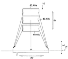
まず、第2配列方向dbにずらして配列された要素ホログラム45からの回折光は、要素ホログラム45の回折特性が特に調整されず互いに同一であると仮定すると、図7を参照して説明したように、当該要素ホログラム45の配列方向である第2配列方向dbに変位して、被照明領域Zがなす面pl上に照射される。そこで、図4に示すように、被照明領域Zの長手方向dlに沿った任意の位置に入射する一つの要素ホログラム45sからの回折光の長手方向dlに直交する幅方向dwに沿った照射幅iwが、被照明領域Zの長手方向dlに沿った前記任意の位置に入射する他の一つの要素ホログラム45kからの回折光の幅方向dwに沿った照射幅iwと、同一となるように、第2配列方向dbに配列された要素ホログラム45の回折特性を調整する。この回折特性の調整は、被照明領域Zの長手方向に沿った全域に亘って行われる。なお、図4は、照明装置10から照明光を照射されて被照明領域Zを含むようになる照射面plへの法線方向ndからの観察により、ホログラム素子40及び被照明領域Zを示す図である。なお、本明細書において、照射幅iwが「同一」とは、照射幅iwのずれが±20%以内であることを意味する。この数値範囲は、本発明者が作製した照明装置10のプロトタイプによる実験結果から導出されたものである。
First, it is assumed that the diffracted light from the
図4に示された例において、各要素ホログラム45から長手方向dlに沿って距離Rだけ離間した被照明領域Z内の位置に向かう光の回折特性を、被照明領域Zの幅に応じて調整する。また、回折特性は、角度空間における拡散角度分布を用いて、調整され得る。まず、基準となる要素ホログラム45sの回折特性を調整する。例えば図4に示された例では、長手方向dlに沿って距離Rだけ離れた位置に向かう基準要素ホログラム45sの拡散角度特性は、図4に示された座標系によって、次のように特定される。
tan(θ1+)=x+/R
tan(θ1−)=x−/R
In the example shown in FIG. 4, the diffraction characteristics of the light traveling toward the position in the illuminated area Z that is separated from each
tan (θ 1+ ) = x + / R
tan (θ 1 − ) = x − / R
次に、他の要素ホログラム45kの拡散角度特性を、基準となる要素ホログラム45sの拡散角度特性と、基準要素ホログラム45sから当該要素ホログラム45kまでの第2配列方向dbに沿ったずれ量aと、を考慮して、決定する。具体的には、つぎのように決定される。
tan(θ2+)=(x++a)/R
tan(θ2−)=(x−−a)/R
Next, the diffusion angle characteristics of the
tan (θ 2+ ) = (x + + a) / R
tan (θ 2− ) = (x − −a) / R
基準要素ホログラム45sの拡散角度特性は、被照明領域Zの長手方向dlに沿った全域に亘って行われる。同様に、他の要素ホログラム45kの拡散角度特性も、被照明領域Zの長手方向dlに沿った全域に亘って行われる。
The diffusion angle characteristic of the reference element hologram 45s is performed over the entire area along the longitudinal direction dl of the illuminated area Z. Similarly, the diffusion angle characteristic of the
次に、第1配列方向daにずらして配列された要素ホログラム45からの回折光は、要素ホログラム45の回折特性が特に調整されず互いに同一であると仮定すると、図8を参照して説明したように、要素ホログラム45から見た正面方向および当該正面方向に垂直な方向の両方に変位して、すなわち図示された例では、被照明領域Zが位置する面pl上において被照明領域Zの長手方向dl及び幅方向dwの両方に変位して照射される。そこで、第2配列方向dbにずらして配列された要素ホログラム45の回折特性の調整と同様にして、一具体例として図4を参照して説明した角度空間での回折特性の調整と同様にして、被照明領域Zの長手方向dlに沿った任意の位置に入射する一つの要素ホログラム45sからの回折光の長手方向dlに直交する幅方向dwに沿った照射幅iwが、被照明領域Zの長手方向dlに沿った前記任意の位置に入射する他の要素ホログラム45t,45nからの回折光の幅方向dwに沿った照射幅iwと、同一となるように、第1配列方向daに配列された要素ホログラム45の回折特性を調整する。
Next, the diffracted light from the
さらに、図5に示すように、被照明領域Zの幅方向dwに沿った任意の位置に入射する一つの要素ホログラム45sからの回折光の長手方向dlに沿った照射長さilが、被照明領域Zの幅方向dwに沿った前記任意の位置に入射する他の一つの要素ホログラム45t,45nからの回折光の長手方向dlに沿った照射長さilと、同一となるように、第1配列方向daに配列された要素ホログラム45の回折特性を調整する。なお、図5は、被照明領域Zがなす照射面plへの法線方向ndと第1配列方向daとの両方に平行な面で、ホログラム素子40及び被照明領域Zを示す図である。なお、本明細書において、照射長さilが「同一」とは、照射長さilのずれが±20%以内であることを意味する。この数値範囲は、本発明者が作製した照明装置10のプロトタイプによる実験結果から導出されたものである。
Further, as shown in FIG. 5, the irradiation length il along the longitudinal direction dl of the diffracted light from one element hologram 45s incident on an arbitrary position along the width direction dw of the illuminated region Z is expressed as follows. The first length is set to be the same as the irradiation length il along the longitudinal direction dl of the diffracted light from the other one of the element holograms 45t and 45n incident on the arbitrary position along the width direction dw of the region Z. The diffraction characteristics of the
図5に示された例において、第1配列方向daに配列された要素ホログラム45から幅方向dwにおける任意の位置に向かう光の回折特性を、被照明領域Zの長さに応じて調整する。また、回折特性は、角度空間における拡散角度分布を用いて、調整され得る。まず、基準となる要素ホログラム45sの回折特性を調整する。例えば図5に示された例では、幅方向dwにおける任意の位置に向かう基準要素ホログラム45sの拡散角度特性は、図5に示された座標系によって、次のように特定される。
tan(θ3+)=h/y
tan(θ3−)=h/(y+il)
なお、式中の「h」は、被照明領域Zが形成される照射面plから基準要素ホログラム45までの第1配列方向daに沿った距離、すなわち基準要素ホログラム45の配置された位置の高さに相当する。
In the example shown in FIG. 5, the diffraction characteristics of light traveling from the
tan (θ 3+ ) = h / y
tan (θ 3 − ) = h / (y + il)
Note that “h” in the equation is the distance along the first arrangement direction da from the irradiation surface pl where the illuminated region Z is formed to the
次に、基準要素ホログラム45sと同一の第1ホログラム素子40aに含まれた他の要素ホログラム45tの拡散角度特性を、基準となる要素ホログラム45sの拡散角度特性と、基準要素ホログラム45sから当該要素ホログラム45tまでの第1配列方向daに沿ったずれ量bと、を考慮して、決定する。具体的には、つぎのように決定される。なお、本明細書において、拡散角度特性が「同一」とは、拡散角度特性のずれが±20%以内であることを意味する。この数値範囲は、本発明者が作製した照明装置10のプロトタイプによる実験結果から導出されたものである。
tan(θ4+)=(h−b)/y
tan(θ4−)=(h−b)/(y+il)
Next, the diffusion angle characteristic of the other element hologram 45t included in the same
tan (θ 4+ ) = (h−b) / y
tan (θ 4 − ) = (h−b) / (y + il)
さらに、基準要素ホログラム45sと異なるホログラム素子40に含まれた他の要素ホログラム45nについても、同様に、拡散特性を決定することができる。すなわち、第3ホログラム素子40cに含まれた他の要素ホログラム45nの拡散角度特性を、基準となる要素ホログラム45sの拡散角度特性と、基準要素ホログラム45sから当該要素ホログラム45nまでの第1配列方向daに沿ったずれ量cと、を考慮して、決定することができる。具体的には、つぎのように決定される。
tan(θ5+)=(h−c)/y
tan(θ5−)=(h−c)/(y+il)
Further, the diffusion characteristics can be similarly determined for other element holograms 45n included in the
tan (θ 5+ ) = (h−c) / y
tan (θ 5 − ) = (h−c) / (y + il)
基準要素ホログラム45sの長手方向dlへの拡散角度特性は、被照明領域Zの幅方向dwに沿った全域に亘って行われる。同様に、他の要素ホログラム45t,45nの拡散角度特性も、被照明領域Zの幅方向dwに沿った全域に亘って行われる。 The diffusion angle characteristic in the longitudinal direction dl of the reference element hologram 45s is performed over the entire area along the width direction dw of the illuminated region Z. Similarly, the diffusion angle characteristics of the other element holograms 45t and 45n are also performed over the entire area along the width direction dw of the illuminated area Z.
以上のようにホログラム素子40及び要素ホログラム45の回折特性を調整することで、各ホログラム素子40からの回折光が、それぞれ、被照明領域Zのみをその全域に亘って照明し、また、各要素ホログラム45からの回折光が、それぞれ、被照明領域Zのみをその全域に亘って照明するようになる。
By adjusting the diffraction characteristics of the
以上に説明した本実施の形態によれば、複数のホログラム素子40の配置位置の相違に応じて各ホログラム素子40の回折特性が調整され、その結果として、各ホログラム素子40からの回折光が、それぞれ、被照明領域Zを照明するようになっている。したがって、複数のホログラム素子40からの回折光が同一波長域の光であれば、被照明領域Zを明るく照明することができる。また、複数のホログラム素子40からの回折光が異なる波長域の光であれば、加法混色による所望の色で被照明領域Zを照明することができる。そして本実施の形態では、各ホログラム素子40からの回折光が、それぞれ、被照明領域Zを照明するので、発光点が分散されることになり、照明装置10を直視した人間の目に対する悪影響の程度を小さくすることができる。加えて、各ホログラム素子40からの回折光が、それぞれ、被照明領域Zの全域を照明するので、被照明領域Zのエッジ近傍における明るさのムラや色のムラを効果的に抑制することができる。これらにより、被照明領域Zを、そのエッジを鮮明としながら、安全に照明することができる。
According to the present embodiment described above, the diffraction characteristics of each
また、本実施の形態では、ホログラム素子40での回折光により、長手方向dlを有する被照明領域Zを照明することになる。したがって、ホログラム素子40の回折特性を調整することで、被照明領域Zが照明装置10の前方に位置し且つ照明装置10から離間する方向に長手方向dlを有する場合であっても、照明装置10から離間した遠くの領域をより高い光照射強度で明るく照明することが可能となる。この結果、長手方向dlを有する被照明領域Z、例えば幅方向dwの長さに対する長手方向dlの長さの比が10以上、さらにはこの比が100以上となる被照明領域Z、さらに典型的にはライン状の被照明領域Zを、そのエッジを鮮明としながら、安全に照明することができる。
In the present embodiment, the illuminated area Z having the longitudinal direction dl is illuminated by the diffracted light from the
なお、複数のホログラム素子40が、被照明領域Zの長手方向dlに垂直な方向であって且つ被照明領域Zが形成される面plへの法線方向ndと平行な第1配列方向daに、配列されている場合における各ホログラム素子40の回折特性の調整方法として、被照明領域Zの長手方向dlに直交する幅方向dwに沿った任意の位置に入射する一つのホログラム素子40からの回折光の長手方向dlに沿った照射長さilが、被照明領域Zの幅方向dwに沿った前記任意の位置に入射する他の一つのホログラム素子40からの回折光の長手方向dlに沿った照射長さilと、同一となるようにし、さらに、被照明領域Zの長手方向dlに沿った任意の位置に入射する一つのホログラム素子40からの回折光の幅方向dwに沿った照射幅iwが、被照明領域Zの長手方向dlに沿った前記任意の位置に入射する他の一つのホログラム素子40からの回折光の幅方向dwに沿った照射幅iwと、同一となるようにしてもよい。このような調整は、照明装置10を簡易小型化しながら実現することが可能である。したがって、照明装置10の簡易小型化を可能としながら、長手方向dlを有する被照明領域Z、典型的にはライン状の被照明領域Zを、そのエッジを鮮明としながら、安全に照明することができる。
The plurality of
また、本実施の形態によれば、ホログラム素子40が複数の要素ホログラム45を含んでいる。そして、複数の要素ホログラム45の配置位置の相違に応じて各要素ホログラム45の回折特性が調整され、その結果として、各要素ホログラム45からの回折光が、それぞれ、被照明領域Zの全域を照明する。したがって、被照明領域Zのエッジ近傍における明るさのムラを効果的に抑制することができる。これにより、被照明領域Zを、そのエッジを鮮明としながら、照明することができる。また、一つのホログラム素子40が、要素ホログラム45の数量と同数の発光点を有することになり、照明装置10を直視した人間の目に対する悪影響の程度を小さくすることができる。加えて、各要素ホログラム45からの回折光が被照明領域Zで重ね合わされることになるので、レーザー光を用いた場合においても、スペックルを効果的に目立たなくすることができる。
Further, according to the present embodiment, the
さらに、各要素ホログラム45での回折光により、長手方向dlを有する被照明領域Zを照明することになる。したがって、要素ホログラム45の回折特性を調整することで、被照明領域Zが照明装置10の前方に位置し且つ照明装置10から離間する方向に長手方向dlを有する場合であっても、照明装置10から離間した遠くの領域をより高い光照射強度で明るく照明することが可能となる。この結果、長手方向dlを有する被照明領域Z、典型的にはライン状の被照明領域Zを、そのエッジを鮮明としながら、安全に照明することができる。
Furthermore, the illuminated area Z having the longitudinal direction dl is illuminated by the diffracted light from each
なお、複数の要素ホログラム45が、被照明領域Zの長手方向dlに垂直であって且つ被照明領域Zが形成される面plへの法線方向ndに垂直な第2配列方向dbに、配列されている場合における各要素ホログラム45の回折特性の調整方法として、被照明領域Zの長手方向dlに沿った任意の位置に入射する一つの要素ホログラム45からの回折光の長手方向dlに直交する幅方向dwに沿った照射幅iwが、被照明領域Zの長手方向dlに沿った前記任意の位置に入射する他の一つ要素ホログラム45からの回折光の幅方向dwに沿った照射幅iwと、同一となるようにしてもよい。このような調整は、照明装置10を簡易小型化しながら実現することが可能である。したがって、照明装置10の簡易小型化を可能としながら、長手方向dlを有する被照明領域Z、典型的にはライン状の被照明領域Zを、そのエッジを鮮明としながら、安全に照明することができる。
The plurality of
また、複数の要素ホログラム45が、被照明領域Zの長手方向dlに垂直な方向であって且つ被照明領域Zが形成される面plへの法線方向ndと平行な第1配列方向daに、配列されている場合における各要素ホログラム45の回折特性の調整方法として、被照明領域Zの長手方向dlに直交する幅方向dwに沿った任意の位置に入射する一つの要素ホログラム45からの回折光の長手方向dlに沿った照射長さilが、被照明領域Zの幅方向dwに沿った前記任意の位置に入射する他の一つの要素ホログラム45からの回折光の長手方向dlに沿った照射長さilと、同一となるようにし、さらに、被照明領域Zの長手方向dlに沿った任意の位置に入射する一つの要素ホログラム45からの回折光の幅方向dwに沿った照射幅iwが、被照明領域Zの長手方向dlに沿った前記任意の位置に入射する他の一つの要素ホログラム45からの回折光の幅方向dwに沿った照射幅iwと、同一となるようにしてもよい。このような調整は、照明装置10を簡易小型化しながら実現することが可能である。したがって、照明装置10の簡易小型化を可能としながら、長手方向dlを有する被照明領域Z、典型的にはライン状の被照明領域Zを、そのエッジを鮮明としながら、安全に照明することができる。
In addition, the plurality of
さらに、上述した一実施の形態において、光源装置15は、レーザー光を生成する光源20と、光源20から射出した光を整形する整形光学系30と、を有している。とりわけ図示された例において、整形光学系30は、光源20からの光を平行光束に変換する。したがって、ホログラム素子40の各要素ホログラム45に平行光束が入射することになる。この例によれば、ホログラム素子40及び要素ホログラム45の設計及び製作を容易化することができる。また、ホログラム素子40での回折によって、光を被照明領域Z内の全域に高精度に向けることが可能となる。
Further, in the above-described embodiment, the
なお、上述した一実施の形態に対して様々な変更を加えることが可能である。以下、図面を参照しながら、変形の一例について説明する。以下の説明および以下の説明で用いる図面では、上述した実施の形態と同様に構成され得る部分について、上述の実施の形態における対応する部分に対して用いた符号と同一の符号を用いるとともに、重複する説明を省略する。 Various modifications can be made to the above-described embodiment. Hereinafter, an example of modification will be described with reference to the drawings. In the following description and the drawings used in the following description, the same reference numerals as those used for the corresponding parts in the above-described embodiment are used for parts that can be configured in the same manner as in the above-described embodiment, and overlapping Description to be omitted is omitted.
上述した一実施の形態において、図1に示すように、複数のホログラム素子40が、被照明領域Zの長手方向dlに垂直であって且つ被照明領域Zが形成される面plへの法線方向ndと平行となる第1配列方向daに、配列されている例を示した。すなわち、被照明領域Zが地面や水面等の水平面に設けられる場合、複数のホログラム素子40が鉛直方向に配列される例を示した。しかしながら、この例に限られず、複数のホログラム素子40が、図6に示すように配列されていてもよい。図6に示された例において、複数のホログラム素子40は、被照明領域Zの長手方向dlに垂直であって且つ被照明領域Zが形成される面plへの法線方向ndに垂直となる方向、すなわち上述した第2配列方向dbに、配列されている。より具体的には、被照明領域Zが地面や水面等の水平面に設けられる場合に、複数のホログラム素子40が水平方向に配列されるようにしてもよい。この例においても、複数のホログラム素子40の配置位置の相違に応じて各ホログラム素子40の回折特性が調整され、その結果として、各ホログラム素子からの回折光が、それぞれ、被照明領域Zの全域を照明することが可能となる。このようにホログラム素子40の回折特性を調整することで、上述した実施の形態と同様の作用効果を奏することができる。
In the above-described embodiment, as shown in FIG. 1, the plurality of
なお、複数のホログラム素子40が、被照明領域Zの長手方向dlに垂直であって且つ被照明領域Zが形成される面plへの法線方向ndに垂直な第2配列方向dbに、配列されている場合における各ホログラム素子40の回折特性の調整方法として、図4を参照して説明したように、被照明領域Zの長手方向dlに沿った任意の位置に入射する一つのホログラム素子40からの回折光の長手方向dlに直交する幅方向dwに沿った照射幅iwが、被照明領域Zの長手方向dlに沿った前記任意の位置に入射する他の一つホログラム素子40からの回折光の幅方向dwに沿った照射幅iwと、同一となるようにしてもよい。このような調整は、照明装置10を簡易小型化しながら実現することが可能である。したがって、照明装置10の簡易小型化を可能としながら、長手方向dlを有する被照明領域Z、典型的にはライン状の被照明領域Zを、そのエッジを鮮明としながら、安全に照明することができる。
The plurality of
また、上述した一実施の形態において、ホログラム素子40が、複数の要素ホログラム45に区分けされている例について説明した。しかしながら、この例に限られず、各ホログラム素子40が、単一のホログラムとして形成されていてもよい。このような変形例においても、照明装置10に含まれた複数のホログラム素子40の各々からの回折光が、それぞれ、被照明領域Zの全域に入射するようにすることで、長手方向を有する被照明領域、典型的にはライン状の被照明領域を、そのエッジを鮮明としながら、安全に照明することができる。
In the above-described embodiment, the example in which the
さらに、上述した一実施の形態において、照明装置10が複数のホログラム素子40を有する例を示したが、この例に限られず、照明装置10が単一のホログラム素子40のみを有するようにしてもよい。この例において、ホログラム素子40が、複数の要素ホログラム45を含んでおり、各要素ホログラム45からの回折光が、それぞれ、被照明領域Zの全域に入射するようにすることで、長手方向を有する被照明領域、典型的にはライン状の被照明領域を、そのエッジを鮮明としながら、安全に照明することができる。
Furthermore, in the above-described embodiment, an example in which the
さらに、上述した一実施の形態において、複数のホログラム素子40の各々に対して、それぞれ別個の光源装置15が用意されている例を示したが、これに限られない。光源20、整形光学系30及びレンズ31のうちのいずれか一つを、複数のホログラム素子40間で共用してもよい。
Furthermore, in the above-described embodiment, an example in which a separate
さらに、図9に示すように、光源装置15の第1〜第3レーザー光源20a〜20cのそれぞれは、長軸方向d1およびこれに直交する短軸方向d2を有する第1発光部151と、第2発光部152と、第3発光部153とを有していてもよい。なお、図9では、便宜上、第1〜第3レーザー光源20a〜20c、第1〜第3整形光学系30a〜30cおよび第1〜第3ホログラム素子40a〜40cのそれぞれを1つにまとめて図示している。実際のレーザー光源20a〜20c、整形光学系30a〜30cおよびホログラム素子40a〜40cは、図1に示したように鉛直方向に配列されていてもよく、または、図6に示したように、水平方向に配列されていてもよい。
Furthermore, as shown in FIG. 9, each of the first to third
ここで、発光部151〜153の長軸方向d1とは、発光部151〜153から発光されるレーザー光の拡散方向のうち拡散角度が最大となる方向である。長軸方向d1は、光軸に直交するレーザー光の断面の最大径に平行な方向ということもできる。図示されている例において、長軸方向d1は、鉛直方向に一致する。また、短軸方向d2とは、発光部151〜153から発光されるレーザー光の拡散方向のうち拡散角度が最小となる方向である。短軸方向d2は、光軸に直交するレーザー光の断面の最小径に平行な方向ということもできる。図示されている例において、短軸方向d2は、水平方向に一致する。
Here, the major axis direction d1 of the
発光部151〜153は、短軸方向d2において同一の位置に、長軸方向d1に間隔を空けて配置されている。すなわち、レーザー光源20a〜20cは、それらの発光部151〜153の短軸方向d2が被照明領域Zの幅方向dwすなわち水平方向に平行となる姿勢で光源装置15の筐体150内に配置されている。
The
このように配置されたレーザー光源20a〜20cの発光部151〜153から短軸方向d2に拡がるように出射されたレーザー光Lは、整形光学系30a〜30cで整形された後に、ホログラム素子40a〜40cで幅方向dwに拡がるように整形される。
The laser light L emitted from the
もし、長軸方向d1が幅方向dwに平行な場合、発光部151〜153は、幅方向dwに大きい拡散角度で拡散したレーザー光を出射する。拡散角度が大きいレーザー光は、整形光学系30a〜30cのコリメートレンズ32a〜32cで十分に平行化することが困難である。平行化が不十分なレーザー光をホログラム素子40a〜40cで所期のビーム形状を有する回折光に整形しようとする場合、ホログラム素子40a〜40cの形状に負担がかかり、ホログラム素子40a〜40cのコストが上昇や寸法精度の悪化を招く虞がある。
If the major axis direction d1 is parallel to the width direction dw, the
これに対して、図9に示される例によれば、発光部151〜153から幅方向dwに小さい拡散角度でレーザー光Lを出射できる。拡散角度が小さいレーザー光Lは、整形光学系30a〜30cのコリメートレンズ32a〜32cで十分に平行化することができるので、ホログラム素子40a〜40cの形状に負担をかけずに所期のビーム形状を有する回折光を得ることができる。
On the other hand, according to the example shown in FIG. 9, the laser beam L can be emitted from the
したがって、図9に示される例によれば、路面上にエッジが明確なライン状の光を確実かつ低コストで照明できる。 Therefore, according to the example shown in FIG. 9, it is possible to illuminate the line-shaped light with a clear edge on the road surface reliably and at low cost.
上述した図4は、照明領域の長手方向に直交する幅方向の中心位置を通って長手方向に延びる中心線L1がホログラム素子40の中心位置を通って長手方向に延びる照明光線を被照明領域Zのある面に投影した投影線L2と一致している例を示したが、図10に示すように、被照明領域Zの上述した中心線L1が投影線L2からずれていてもよい。
In FIG. 4 described above, the illumination light beam Z extends the illumination light beam in which the center line L1 extending in the longitudinal direction through the center position in the width direction orthogonal to the longitudinal direction of the illumination area extends in the longitudinal direction through the center position of the
図10では、図4と同様に、被照明領域Zの短手方向の幅をiw、ホログラム素子40の水平方向の幅をa、ホログラム素子40から被照明領域Zの最近接位置までの最短距離をR、被照明領域Zの長手方向の第1エッジe1とホログラム素子40の水平方向の第1端部を通過して被照明領域Zの長手方向に延びる第1端線e2との距離をx+、被照明領域Zの長手方向の第2エッジe3とホログラム素子40の水平方向の第2端部を通過して被照明領域Zの長手方向に延びる第2端線e4との距離をx-としている。また、被照明領域Zの任意の位置を通って短軸方向の境界位置をp1とp2としたときに、位置p1と第1端線e2との為す角度をθ1+、位置p2と第1端線e2との為す角度をθ1-、位置p1と第2端線e4との為す角度をθ2+、位置p2と第2端線e4との為す角度をθ2-とすると、以下の式が成り立つ。
In FIG. 10, as in FIG. 4, the width in the short direction of the illuminated area Z is iw, the horizontal width of the
tan(θ1+)=x+/R
tan(θ1−)=(x+―iw)/R
tan(θ2+)=(x++a)/R
tan(θ2−)=x-/R
tan (θ 1+ ) = x + / R
tan (θ 1 − ) = (x + −iw) / R
tan (θ 2+ ) = (x + + a) / R
tan (θ 2− ) = x − / R
このように、上記の式を満たすように、ホログラム素子40の回折特性を設計することにより、ホログラム素子40に対して任意の方向および位置にある被照明領域Zを照明することができる。
In this way, by designing the diffraction characteristics of the
ホログラム素子40に入射されたレーザー光の一部は、ホログラム素子40で回折されることなく、そのまま透過する0次光となる。0次光が被照明領域Zに照射される場合、予め設計された被照明領域Z内の0次光照射位置だけが特異的に照度が高くなってしまう。ホログラム素子40の位置を基準として、0次光が被照明領域Zの長手方向における最近端側に照射される場合と最遠端側に照射される場合とを比較すると、最近端側に照射される場合の方が0次光の照射面積が小さくなって、単位面積当たりの照度が高くなり、被照明領域Zにおける0次光の照射位置が目立ちやすくなる。そこで、0次光が被照明領域Zの長手方向における最近端よりも最遠端側に入射されるように、ホログラム素子40の回折特性を設計するのが望ましい。これにより、被照明領域Zの全域での光強度すなわち照度のばらつきを抑制できる。
A part of the laser light incident on the
図1等では、整形光学系30a〜30cのコリメートレンズ32a〜32cにてレーザー光を平行化した後にホログラム素子40a〜40cに入射している。被照明領域Zのボケを抑制するには、ホログラム素子40a〜40cへの入射光を平行化するのが望ましいが、平行化されたレーザ光は、ホログラム素子40a〜40cへの入射面積が小さいため、その分、0次光の光強度が大きくなる。よって、0次光の光強度を弱める観点からは、ホログラム素子40a〜40cへの入射光が完全な平行光よりもわずかに広がった拡散光の方が望ましい。拡散光がホログラム素子40a〜40cに入射されると、被照明領域Zのボケ量が増大するおそれがあるが、図3等で説明したように、ホログラム素子40a〜40cが複数の要素ホログラム45に区分けされていて、各要素ホログラム45が被照明領域Zの全域を照明するような回折特性を持っている場合には、ホログラム素子40a〜40cへの入射光が拡散光であったとしても、各要素ホログラム45内に入射されるレーザー光の入射角度はほとんど同じと考えられるため、各要素ホログラム45ごとに被照明領域Zの全域を照明するように回折特性を設計すれば、ホログラム素子40a〜40cの全体として、被照明領域Zを鮮明に照明することができる。
In FIG. 1 and the like, the laser light is collimated by collimating
図1等では、回折光学素子として、透過型のホログラム素子40a〜40cを用いる例を示したが、図11に示すように反射型のホログラム素子40a〜40cを用いてもよい。反射型のホログラム素子40a〜40cであれば、0次光の進行方向が観察者の観察方向と異なるため、0次光に対する安全対策が容易になりうる。
In FIG. 1 and the like, an example in which transmissive
なお、以上において上述した実施の形態に対するいくつかの変形例を説明してきたが、当然に、複数の変形例を適宜組み合わせて適用することも可能である。 In addition, although the some modification with respect to embodiment mentioned above was demonstrated above, naturally, it is also possible to apply combining several modifications suitably.
dl 長手方向
dw 幅方向
da 第1配列方向
db 第2配列方向
Z 被照明領域
Za 照明領域
Zb 照明領域
Zx 被照明領域
Zy 両縁部分
Zz 周縁部分
10 照明装置
15 光源装置
20 光源
20a 第1レーザー光源
20b 第2レーザー光源
20c 第3レーザー光源
30 整形光学系
30a 第1整形光学系
30b 第2整形光学系
30c 第3整形光学系
31 レンズ
31a 第1レンズ
31b 第2レンズ
31c 第3レンズ
32 コリメートレンズ
32a 第1コリメートレンズ
32b 第2コリメートレンズ
32c 第3コリメートレンズ
40 ホログラム素子
40a 第1ホログラム素子
40b 第2ホログラム素子
40c 第3ホログラム素子
45 要素ホログラム
45a 第1要素ホログラム
45b 第2要素ホログラム
45c 第3要素ホログラム
60 ホログラム
60a 第1ホログラム
60b 第2ホログラム
dl Longitudinal direction dw Width direction da First arrangement direction db Second arrangement direction Z Illuminated area Za Illuminated area Zb Illuminated area Zx Illuminated area Zy Both-edge part Zz
Claims (9)
光源と、
前記光源からの光を回折して、それぞれの出射面から前記被照明領域に向けて光を出射する第1ホログラム素子及び第2ホログラム素子を有する回折光学素子と、を備え、
前記第1ホログラム素子での回折光が前記被照明領域の全域を照明し且つ前記第2ホログラム素子での回折光が前記被照明領域の全域を照明し、
前記第1ホログラム素子及び前記第2ホログラム素子は、前記被照明領域の前記第1方向に交差する方向に配列されており、
前記第1ホログラム素子及び前記第2ホログラム素子は、前記第1ホログラム素子及び前記第2ホログラム素子の出射面の法線方向が、前記被照明領域が形成される面の法線方向に交差するように、配置されており、
前記第1ホログラム素子及び前記第2ホログラム素子の少なくとも一方は、複数の要素ホログラムを含み、
前記複数の要素ホログラムのそれぞれからの回折光は、前記被照明領域の全域を照明する、照明装置。 An illumination device that illuminates an illuminated area that extends in a first direction and extends in a second direction that intersects the first direction,
A light source;
Diffracts the light from the light source includes a diffractive optical element from the respective exit surface having a first hologram element and a second hologram element that shines out of the light toward the illuminated area, and
The diffracted light at the first hologram element illuminates the entire area of the illuminated area, and the diffracted light at the second hologram element illuminates the entire area of the illuminated area,
The first hologram element and the second hologram element are arranged in a direction intersecting the first direction of the illuminated area ,
In the first hologram element and the second hologram element, the normal direction of the emission surface of the first hologram element and the second hologram element intersects the normal direction of the surface on which the illuminated area is formed. Are arranged ,
At least one of the first hologram element and the second hologram element includes a plurality of element holograms,
The diffracted light from each of the plurality of element holograms illuminates the entire illuminated area.
光源と、
前記光源からの光を回折して、それぞれの出射面から前記被照明領域に向けて光を出射する第1ホログラム素子及び第2ホログラム素子を有する回折光学素子と、を備え、
前記被照明領域の前記第1方向と前記第2方向との少なくとも一方において、前記第1ホログラム素子からの回折光の照明範囲は、前記第2ホログラム素子からの回折光の照明範囲に揃っており、
前記第1ホログラム素子及び前記第2ホログラム素子は、前記被照明領域の前記第1方向に交差する方向に配列されており、
前記第1ホログラム素子及び前記第2ホログラム素子は、前記第1ホログラム素子及び前記第2ホログラム素子の出射面の法線方向が、前記被照明領域が形成される面の法線方向に交差するように、配置されており、
前記第1ホログラム素子及び前記第2ホログラム素子の少なくとも一方は、複数の要素ホログラムを含み、
前記複数の要素ホログラムのそれぞれからの回折光は、前記被照明領域の全域を照明する、照明装置。 An illumination device that illuminates an illuminated area that extends in a first direction and extends in a second direction that intersects the first direction,
A light source;
Diffracts the light from the light source includes a diffractive optical element from the respective exit surface having a first hologram element and a second hologram element that shines out of the light toward the illuminated area, and
In at least one of the first direction and the second direction of the illuminated area, the illumination range of the diffracted light from the first hologram element is aligned with the illumination range of the diffracted light from the second hologram element. ,
Wherein the first holographic element and said second holographic element, the are arranged in a direction intersecting the first direction of the illuminated region,
In the first hologram element and the second hologram element, the normal direction of the emission surface of the first hologram element and the second hologram element intersects the normal direction of the surface on which the illuminated area is formed. Are arranged ,
At least one of the first hologram element and the second hologram element includes a plurality of element holograms,
The diffracted light from each of the plurality of element holograms illuminates the entire illuminated area.
前記被照明領域の前記第1方向に沿った任意の位置に入射する一つの要素ホログラムからの回折光の前記第1方向に交差する前記第2方向に沿った照射幅は、前記被照明領域の前記第1方向に沿った前記任意の位置に入射する他の一つの要素ホログラムからの回折光の前記第2方向に沿った照射幅と、同一となっている、請求項1乃至6のいずれか一項に記載の照明装置。 It said plurality of element holograms, the are arranged in a direction intersecting the first direction of the illuminated region,
The irradiation width along the second direction crossing the first direction of the diffracted light from one element hologram incident at any position along the first direction of the illuminated region of the illuminated area an irradiation width along the second direction of the diffracted light from the other one of the element holograms to be incident on the arbitrary position along the first direction, are the same, any one of claims 1 to 6 The lighting device according to one item.
前記被照明領域の前記第1方向に交差する前記第2方向に沿った任意の位置に入射する一つの要素ホログラムからの回折光の前記第1方向に沿った照射長さは、前記被照明領域の前記第2方向に沿った前記任意の位置に入射する他の一つの要素ホログラムからの回折光の前記第1方向に沿った照射長さと、同一となっており、
前記被照明領域の前記第1方向に沿った任意の位置に入射する前記一つの要素ホログラムからの回折光の前記第2方向に沿った照射幅は、前記被照明領域の前記第1方向に沿った前記任意の位置に入射する他の一つの要素ホログラムからの回折光の前記第2方向に沿った照射幅と、同一となっている、請求項1乃至7のいずれか一項に記載の照明装置。 It said plurality of element holograms, the are arranged in a direction intersecting the first direction of the illuminated region,
The irradiation length along the first direction of the diffracted light from one element hologram incident at any position along the second direction crossing the first direction of the illuminated area, the illuminated area The irradiation length along the first direction of the diffracted light from the other one element hologram incident on the arbitrary position along the second direction is the same,
The irradiation width along the second direction of the diffracted light from the one element hologram incident on an arbitrary position along the first direction of the illuminated area is along the first direction of the illuminated area. The illumination according to any one of claims 1 to 7 , wherein the illumination width is the same as an irradiation width along the second direction of diffracted light from another element hologram incident on the arbitrary position. apparatus.
前記第1コヒーレント光源からの光を整形して前記第1ホログラム素子に向ける第1整形光学系と、前記第2コヒーレント光源からの光を整形して前記第2ホログラム素子に向ける第2整形光学系と、をさらに備える、請求項1乃至8のいずれか一項に記載の照明装置。 The light source includes a first coherent light source and a second coherent light source,
A first shaping optical system that shapes light from the first coherent light source and directs the light toward the first hologram element, and a second shaping optical system that shapes light from the second coherent light source and directs the light to the second hologram element The lighting device according to any one of claims 1 to 8 , further comprising:
Priority Applications (4)
| Application Number | Priority Date | Filing Date | Title |
|---|---|---|---|
| PCT/JP2017/006068 WO2017145972A1 (en) | 2016-02-24 | 2017-02-20 | Lighting device |
| CN201780012675.XA CN108700266B (en) | 2016-02-24 | 2017-02-20 | Lighting device |
| US16/078,833 US10690932B2 (en) | 2016-02-24 | 2017-02-20 | Lighting device |
| EP17756410.1A EP3421868A4 (en) | 2016-02-24 | 2017-02-20 | Lighting device |
Applications Claiming Priority (4)
| Application Number | Priority Date | Filing Date | Title |
|---|---|---|---|
| JP2016033224 | 2016-02-24 | ||
| JP2016033224 | 2016-02-24 | ||
| JP2016147678 | 2016-07-27 | ||
| JP2016147678 | 2016-07-27 |
Related Child Applications (1)
| Application Number | Title | Priority Date | Filing Date |
|---|---|---|---|
| JP2018098957A Division JP6803009B2 (en) | 2016-02-24 | 2018-05-23 | Lighting device |
Publications (3)
| Publication Number | Publication Date |
|---|---|
| JP2018025742A JP2018025742A (en) | 2018-02-15 |
| JP2018025742A5 JP2018025742A5 (en) | 2018-04-05 |
| JP6344463B2 true JP6344463B2 (en) | 2018-06-20 |
Family
ID=61195623
Family Applications (2)
| Application Number | Title | Priority Date | Filing Date |
|---|---|---|---|
| JP2016249894A Active JP6344463B2 (en) | 2016-02-24 | 2016-12-22 | Lighting device |
| JP2018098957A Active JP6803009B2 (en) | 2016-02-24 | 2018-05-23 | Lighting device |
Family Applications After (1)
| Application Number | Title | Priority Date | Filing Date |
|---|---|---|---|
| JP2018098957A Active JP6803009B2 (en) | 2016-02-24 | 2018-05-23 | Lighting device |
Country Status (4)
| Country | Link |
|---|---|
| US (1) | US10690932B2 (en) |
| EP (1) | EP3421868A4 (en) |
| JP (2) | JP6344463B2 (en) |
| CN (1) | CN108700266B (en) |
Cited By (2)
| Publication number | Priority date | Publication date | Assignee | Title |
|---|---|---|---|---|
| JP7335664B1 (en) | 2023-04-05 | 2023-08-30 | アポロ興産株式会社 | Packaging material manufacturing method |
| US12085739B2 (en) | 2018-10-15 | 2024-09-10 | AGC Inc. | Diffractive optical element and illumination optical system |
Families Citing this family (3)
| Publication number | Priority date | Publication date | Assignee | Title |
|---|---|---|---|---|
| DE102016107307A1 (en) * | 2016-04-20 | 2017-10-26 | Hella Kgaa Hueck & Co. | Lighting device for vehicles |
| JP2021027014A (en) * | 2019-08-08 | 2021-02-22 | 大日本印刷株式会社 | Lighting device and movable body |
| JP6901053B1 (en) | 2021-02-25 | 2021-07-14 | 大日本印刷株式会社 | Lighting system, how to design a lighting system |
Family Cites Families (9)
| Publication number | Priority date | Publication date | Assignee | Title |
|---|---|---|---|---|
| US5186533A (en) * | 1990-01-30 | 1993-02-16 | Nissan Motor Co., Ltd. | Lamp arrangement for motor vehicle |
| DE29920151U1 (en) | 1999-11-17 | 2001-03-29 | Müller, Helmut Frank Ottomar, Prof. Dr.-Ing., 50933 Köln | Illuminated board with holograms |
| JP2003270585A (en) | 2002-03-18 | 2003-09-25 | Ricoh Co Ltd | Laser illumination optical system, and exposure device, laser beam machining device and projection device using the same |
| JP4465956B2 (en) | 2002-12-05 | 2010-05-26 | セイコーエプソン株式会社 | Hologram element manufacturing method and projection display device |
| EP1710619B1 (en) * | 2004-01-29 | 2018-07-04 | Panasonic Intellectual Property Management Co., Ltd. | Light source device, and two-dimensional image display unit |
| US9377759B2 (en) | 2010-09-08 | 2016-06-28 | Dai Nippon Printing Co., Ltd. | Illumination device, projection apparatus and projection-type image display apparatus |
| MX2013002833A (en) | 2010-09-14 | 2013-04-05 | Dynamic Digital Depth Res Pty | A method for enhancing depth maps. |
| JP2012230360A (en) | 2011-04-15 | 2012-11-22 | Dainippon Printing Co Ltd | Illumination device, projection device and projection type image display device |
| JP6344545B2 (en) | 2014-01-14 | 2018-06-20 | 大日本印刷株式会社 | Display device and vehicle equipped with display device |
-
2016
- 2016-12-22 JP JP2016249894A patent/JP6344463B2/en active Active
-
2017
- 2017-02-20 EP EP17756410.1A patent/EP3421868A4/en active Pending
- 2017-02-20 US US16/078,833 patent/US10690932B2/en active Active
- 2017-02-20 CN CN201780012675.XA patent/CN108700266B/en active Active
-
2018
- 2018-05-23 JP JP2018098957A patent/JP6803009B2/en active Active
Cited By (2)
| Publication number | Priority date | Publication date | Assignee | Title |
|---|---|---|---|---|
| US12085739B2 (en) | 2018-10-15 | 2024-09-10 | AGC Inc. | Diffractive optical element and illumination optical system |
| JP7335664B1 (en) | 2023-04-05 | 2023-08-30 | アポロ興産株式会社 | Packaging material manufacturing method |
Also Published As
| Publication number | Publication date |
|---|---|
| CN108700266B (en) | 2021-03-30 |
| US20190072776A1 (en) | 2019-03-07 |
| EP3421868A1 (en) | 2019-01-02 |
| JP6803009B2 (en) | 2020-12-23 |
| US10690932B2 (en) | 2020-06-23 |
| EP3421868A4 (en) | 2019-08-21 |
| JP2018025742A (en) | 2018-02-15 |
| CN108700266A (en) | 2018-10-23 |
| JP2018156950A (en) | 2018-10-04 |
Similar Documents
| Publication | Publication Date | Title |
|---|---|---|
| JP6344463B2 (en) | Lighting device | |
| JP6471842B2 (en) | Lighting device | |
| JP7022394B2 (en) | Lighting equipment | |
| US11359785B2 (en) | Illumination device | |
| US11092305B2 (en) | Illumination device | |
| WO2017145972A1 (en) | Lighting device | |
| JP6569958B2 (en) | Lighting device | |
| JP6850424B2 (en) | Light source device and lighting device | |
| JP6939315B2 (en) | Lighting device | |
| JP7131153B2 (en) | Lighting devices and lighting units | |
| JP7092086B2 (en) | Lighting equipment for mobiles and mobiles | |
| JP6936978B2 (en) | Lighting equipment, manufacturing method of lighting equipment, lighting method | |
| JP7011787B2 (en) | Lighting equipment | |
| JP6146680B2 (en) | Lighting device | |
| JP7249510B2 (en) | lighting equipment | |
| JP2019053887A (en) | Luminaire | |
| JP2018163851A (en) | Lighting device | |
| JP2019148711A (en) | Method of designing diffraction characteristic of diffraction optical element, and illumination device |
Legal Events
| Date | Code | Title | Description |
|---|---|---|---|
| A521 | Written amendment |
Free format text: JAPANESE INTERMEDIATE CODE: A523 Effective date: 20180226 |
|
| A621 | Written request for application examination |
Free format text: JAPANESE INTERMEDIATE CODE: A621 Effective date: 20180226 |
|
| A871 | Explanation of circumstances concerning accelerated examination |
Free format text: JAPANESE INTERMEDIATE CODE: A871 Effective date: 20180226 |
|
| A975 | Report on accelerated examination |
Free format text: JAPANESE INTERMEDIATE CODE: A971005 Effective date: 20180228 |
|
| A131 | Notification of reasons for refusal |
Free format text: JAPANESE INTERMEDIATE CODE: A131 Effective date: 20180309 |
|
| A521 | Written amendment |
Free format text: JAPANESE INTERMEDIATE CODE: A523 Effective date: 20180409 |
|
| TRDD | Decision of grant or rejection written | ||
| A01 | Written decision to grant a patent or to grant a registration (utility model) |
Free format text: JAPANESE INTERMEDIATE CODE: A01 Effective date: 20180424 |
|
| A61 | First payment of annual fees (during grant procedure) |
Free format text: JAPANESE INTERMEDIATE CODE: A61 Effective date: 20180507 |
|
| R150 | Certificate of patent or registration of utility model |
Ref document number: 6344463 Country of ref document: JP Free format text: JAPANESE INTERMEDIATE CODE: R150 |