JPWO2004088733A1 - Dummy wafer - Google Patents
Dummy wafer Download PDFInfo
- Publication number
- JPWO2004088733A1 JPWO2004088733A1 JP2005504241A JP2005504241A JPWO2004088733A1 JP WO2004088733 A1 JPWO2004088733 A1 JP WO2004088733A1 JP 2005504241 A JP2005504241 A JP 2005504241A JP 2005504241 A JP2005504241 A JP 2005504241A JP WO2004088733 A1 JPWO2004088733 A1 JP WO2004088733A1
- Authority
- JP
- Japan
- Prior art keywords
- gpa
- layer
- cfrp
- carbon fiber
- dummy wafer
- Prior art date
- Legal status (The legal status is an assumption and is not a legal conclusion. Google has not performed a legal analysis and makes no representation as to the accuracy of the status listed.)
- Granted
Links
Images
Classifications
-
- C—CHEMISTRY; METALLURGY
- C08—ORGANIC MACROMOLECULAR COMPOUNDS; THEIR PREPARATION OR CHEMICAL WORKING-UP; COMPOSITIONS BASED THEREON
- C08J—WORKING-UP; GENERAL PROCESSES OF COMPOUNDING; AFTER-TREATMENT NOT COVERED BY SUBCLASSES C08B, C08C, C08F, C08G or C08H
- C08J5/00—Manufacture of articles or shaped materials containing macromolecular substances
- C08J5/04—Reinforcing macromolecular compounds with loose or coherent fibrous material
- C08J5/0405—Reinforcing macromolecular compounds with loose or coherent fibrous material with inorganic fibres
- C08J5/042—Reinforcing macromolecular compounds with loose or coherent fibrous material with inorganic fibres with carbon fibres
-
- H—ELECTRICITY
- H10—SEMICONDUCTOR DEVICES; ELECTRIC SOLID-STATE DEVICES NOT OTHERWISE PROVIDED FOR
- H10P—GENERIC PROCESSES OR APPARATUS FOR THE MANUFACTURE OR TREATMENT OF DEVICES COVERED BY CLASS H10
- H10P14/00—Formation of materials, e.g. in the shape of layers or pillars
- H10P14/20—Formation of materials, e.g. in the shape of layers or pillars of semiconductor materials
-
- H—ELECTRICITY
- H10—SEMICONDUCTOR DEVICES; ELECTRIC SOLID-STATE DEVICES NOT OTHERWISE PROVIDED FOR
- H10P—GENERIC PROCESSES OR APPARATUS FOR THE MANUFACTURE OR TREATMENT OF DEVICES COVERED BY CLASS H10
- H10P72/00—Handling or holding of wafers, substrates or devices during manufacture or treatment thereof
- H10P72/06—Apparatus for monitoring, sorting, marking, testing or measuring
- H10P72/0606—Position monitoring, e.g. misposition detection or presence detection
-
- C—CHEMISTRY; METALLURGY
- C08—ORGANIC MACROMOLECULAR COMPOUNDS; THEIR PREPARATION OR CHEMICAL WORKING-UP; COMPOSITIONS BASED THEREON
- C08J—WORKING-UP; GENERAL PROCESSES OF COMPOUNDING; AFTER-TREATMENT NOT COVERED BY SUBCLASSES C08B, C08C, C08F, C08G or C08H
- C08J2363/00—Characterised by the use of epoxy resins; Derivatives of epoxy resins
Landscapes
- Chemical & Material Sciences (AREA)
- Inorganic Chemistry (AREA)
- Engineering & Computer Science (AREA)
- Manufacturing & Machinery (AREA)
- Materials Engineering (AREA)
- Health & Medical Sciences (AREA)
- Chemical Kinetics & Catalysis (AREA)
- Medicinal Chemistry (AREA)
- Polymers & Plastics (AREA)
- Organic Chemistry (AREA)
- Laminated Bodies (AREA)
- Reinforced Plastic Materials (AREA)
- Moulding By Coating Moulds (AREA)
Abstract
炭素繊維強化プラスチック(CFRP)を含むダミーウエハ。CFRPを含むウエハ基体を有するダミーウエハであって、基体が各主表面側にある二つのスキン層とその間のコア層を有し、各スキン層は一方向プリプレグの硬化成形物からなる一次元強化層を複数有し、各スキン層中で最も主表面側にある一次元強化層(最外層)の一方の配向方向を基準に、他方の最外層は特定方向に配向し、各最外層のCFの引張弾性率は特定範囲内で、各スキン層は特定方向に配向し引張弾性率が特定範囲内であるCFを含む一次元強化層を有し、コア層が特定方向に配向し引張弾性率が特定範囲内であるCFを含む一次元強化層を有し且つ特定方向に配向し引張弾性率が特定範囲内であるCFを含む一次元強化層を有する。このダミーウエハは高強度、安価でかつ光センサにも反応しやすい。A dummy wafer containing carbon fiber reinforced plastic (CFRP). A dummy wafer having a wafer substrate containing CFRP, the substrate having two skin layers on each main surface side and a core layer therebetween, each skin layer being a one-dimensional reinforced layer made of a cured product of a unidirectional prepreg And the other outermost layer is oriented in a specific direction on the basis of one orientation direction of the one-dimensional reinforcing layer (outermost layer) on the most main surface side in each skin layer, and the CF of each outermost layer The tensile elastic modulus is within a specific range, each skin layer has a one-dimensional reinforcing layer containing CF that is oriented in a specific direction and the tensile elastic modulus is within a specific range, the core layer is oriented in a specific direction, and the tensile elastic modulus is It has a one-dimensional reinforcing layer containing CF within a specific range and has a one-dimensional reinforcing layer containing CF oriented in a specific direction and having a tensile elastic modulus within a specific range. This dummy wafer is high-strength, inexpensive, and easily reacts to the optical sensor.
Description
本発明は、半導体集積回路や半導体メモリなどの半導体製造プロセスにおいて用いられるダミーウエハに関する。 The present invention relates to a dummy wafer used in a semiconductor manufacturing process such as a semiconductor integrated circuit and a semiconductor memory.
従来、半導体集積回路、半導体メモリ等の半導体製造プロセスにおいては、例えば、プラズマエッチング装置、CVD装置、スパッタリング装置等の各種処理装置の稼働テスト、バッチ処理時のウェハーの枚数合わせ、ローディング効果対策等のために、実際のICパターンが形成されていないダミーウェハーを用いて各種処理を行う、いわゆるダミー処理が行われている。また、プラズマCVD装置等の各種プラズマ装置の反応室のクリーニングをプラズマクリーニングにより行う場合に、例えば、基板保持電極をプラズマから保護するためにもダミーウェハーが用いられている。
従来より、半導体デバイスの製造プロセスにおいて使用されるダミーウェハーとしては、以下のようなものがあり、それぞれに問題があった。
(a)シリコン製ダミーウェハー:高価で脆く再使用できない。使用量はウェハーと同数なので半導体製造コストを大幅に押し上げる。
(b)石英製ダミーウェハー:光センサに反応しにくい。
(c)セラミックス製ダミーウェハー:重い。光センサに反応しにくい場合がある。
(d)ガラス状カーボン製ダミーウェハー:発塵の問題がある。
これらの問題を解決するための技術が、例えば特開2002−175959号公報に示されているが、強度等の点において、未だ改善の余地がある。Conventionally, in a semiconductor manufacturing process such as a semiconductor integrated circuit and a semiconductor memory, for example, an operation test of various processing apparatuses such as a plasma etching apparatus, a CVD apparatus, and a sputtering apparatus, alignment of the number of wafers during batch processing, and a loading effect countermeasure Therefore, so-called dummy processing is performed in which various processes are performed using a dummy wafer on which no actual IC pattern is formed. Further, when cleaning a reaction chamber of various plasma apparatuses such as a plasma CVD apparatus by plasma cleaning, for example, a dummy wafer is used to protect the substrate holding electrode from plasma.
Conventionally, the dummy wafers used in the semiconductor device manufacturing process include the following, and each has a problem.
(A) Silicon dummy wafer: expensive and fragile and cannot be reused. Since the amount used is the same as the number of wafers, it greatly increases the cost of semiconductor manufacturing.
(B) Quartz dummy wafer: It is difficult to react to an optical sensor.
(C) Ceramic dummy wafer: heavy. It may be difficult to react to the optical sensor.
(D) Glassy carbon dummy wafer: There is a problem of dust generation.
A technique for solving these problems is disclosed in, for example, Japanese Patent Laid-Open No. 2002-175959, but there is still room for improvement in terms of strength and the like.
本発明は、例えば直径300mm×厚さ0.5mm〜0.75mmという大径で薄型であっても剛性があって高強度であり、比較的安価で、光センサにも反応しやすいダミーウエハを提供することを目的とする。さらに低発塵性のダミーウエハ、また耐熱性があるダミーウェハを提供することを目的とする。
更に好ましくはSEMI規格以下という極めて薄いダミーウェハでもその曲げ剛性が実質的に均一で平面性に優れるダミーウェハを提供することを目的とする。
本発明により、以下のダミーウエハが提供される。
1)炭素繊維強化プラスチックを含むことを特徴とするダミーウエハ。
2)炭素繊維強化プラスチックを含むウエハ基体を有する1)記載のダミーウエハ。
3)前記炭素繊維強化プラスチックが、引張弾性率が400GPa以上の炭素繊維を含む2)記載のダミーウエハ。
4)前記炭素繊維がピッチ系炭素繊維である3)記載のダミーウエハ。
5)前記ウエハ基体が、炭素繊維強化プラスチックからなる層であるCFRP層を複数有する2)記載のダミーウエハ。
6)前記ウエハ基体が、炭素繊維が一方向に配向した一方向プリプレグの硬化成形物からなる炭素繊維強化プラスチックからなる層である一次元強化CFRP層を複数有し、
該複数の一次元強化CFRP層のうちの、一部の層の炭素繊維の引張弾性率が、他の層の炭素繊維の引張弾性率よりも高い5)記載のダミーウエハ。
7)前記ウエハ基体が、それぞれ主表面側に位置する二つのスキン層と、該二つのスキン層の間に位置するコア層とを有し、
該二つのスキン層は、いずれも、前記一次元強化CFRP層を複数有し、
該二つのスキン層のそれぞれにおいて最も主表面側に位置する一次元強化CFRP層である二つの最外CFRP層の一方の炭素繊維の配向方向を基準方向としたとき、他方の最外CFRP層の炭素繊維の配向方向は該基準方向に対して−20°〜+20°の角度範囲にあり、
該二つの最外CFRP層中の炭素繊維の引張弾性率はいずれも200GPa〜600GPaであり、
該二つのスキン層は、いずれも、該基準方向に対して+75°〜+90°の角度範囲に配向し且つ引張弾性率が400GPa〜1000GPaであっていずれの最外CFRP層の炭素繊維の引張弾性率よりも高い炭素繊維を含有する一次元強化CFRP層および/または該基準方向に対して−75°〜−90°の角度範囲に配向し且つ引張弾性率が400GPa〜1000GPaであっていずれの最外CFRP層の炭素繊維の引張弾性率よりも高い炭素繊維を含有する一次元強化CFRP層を有し、
該コア層は、該基準方向に対して+30°〜+60°の角度範囲に配向し且つ引張弾性率が400GPa〜1000GPaである炭素繊維を含有する一次元強化CFRP層および/または−30°〜−60°の角度範囲に配向し且つ引張弾性率が400GPa〜1000GPaである炭素繊維を含有する一次元強化CFRP層を有する6)記載のダミーウエハ。
8)該二つのスキン層のそれぞれの厚さは、該二つのスキン層とコア層の合計の厚さの10%〜45%である7)記載のダミーウエハ。
9)炭素繊維強化プラスチックを含むウエハ基体を有するダミーウエハであって、
前記ウェハ基体が、それぞれ主表面側に位置する二つのスキン層と、該二つのスキン層の間に位置するコア層とを有し、
該二つのスキン層は、いずれも、炭素繊維が一方向に配向した一方向プリプレグの硬化成形物からなる炭素繊維強化プラスチックからなる層である一次元強化CFRP層を複数有し、
該二つのスキン層のそれぞれにおいて最も主表面側に位置する一次元強化CFRP層である二つの最外CFRP層の一方の炭素繊維の配向方向を基準方向としたとき、他方の最外CFRP層の炭素繊維の配向方向は該基準方向に対して−20°〜+20°の角度範囲にあり、
該二つの最外CFRP層の炭素繊維の引張弾性率はいずれも200GPa〜600GPaであり、
該二つのスキン層は、いずれも、該基準方向に対して+75°〜+90°の角度範囲に配向し且つ引張弾性率がそのスキン層に含まれる最外CFRP層の炭素繊維の引張弾性率の1.5倍〜3.0倍である炭素繊維を含有する一次元強化CFRP層および/または該基準方向に対して−75°〜−90°の角度範囲に配向し且つ引張弾性率がそのスキン層に含まれる最外CFRP層の炭素繊維の引張弾性率の1.5倍〜3.0倍である炭素繊維を含有する一次元強化CFRP層を有し、
該コア層が、該基準方向に対して−20°〜+20°の角度範囲に配向し引張弾性率が200GPa〜400GPaである炭素繊維を含有する一次元強化CFRP層を有するとともに、該基準方向に対して+75°〜+90°の角度範囲に配向し引張弾性率が200GPa〜400GPaである炭素繊維を含有する一次元強化CFRP層および/または該基準方向に対して−75°〜−90°の角度範囲に配向し引張弾性率が200GPa〜400GPaである炭素繊維を含有する一次元強化CFRP層を有することを特徴とするダミーウエハ。
10)前記二つのスキン層の少なくとも一方が、更に、前記基準方向に対して+30°〜+60°の角度範囲に配向し且つ引張弾性率がそのスキン層に含まれる最外CFRP層の炭素繊維の引張弾性率の1.5倍〜3.0倍である炭素繊維を含有する一次元強化CFRP層および/または前記基準方向に対して−30°〜−60°の角度範囲に配向し且つ引張弾性率がそのスキン層に含まれる最外CFRP層の炭素繊維の引張弾性率の1.5倍〜3.0倍である炭素繊維を含有する一次元強化CFRP層を有する9)記載のダミーウエハ。
11)さらに、それぞれの主表面に炭素繊維クロス層を有する6)〜10)の何れか一項記載のダミーウェハ。
12)前記炭素繊維強化プラスチックに含まれるマトリックス樹脂が、硬化剤としてジアミノジフェニルスルホンを含むエポキシ樹脂組成物を含む1)〜11)の何れか一項記載のダミーウエハ。
13)前記ウエハ基体が加工面を有し、
該加工面を被覆する、極性溶媒に対して耐性を有しかつ70℃以下の温度で硬化する樹脂からなる被覆層を有する2)〜12)の何れか一項記載のダミーウエハ。
本明細書において、数値範囲を表す「X1〜X2」という表現は、別段の断りがない限り、X1とX2との間の範囲であってX1およびX2を含む範囲を意味する。The present invention provides, for example, a dummy wafer having a large diameter of 300 mm × thickness of 0.5 mm to 0.75 mm, which is rigid and high in strength, relatively inexpensive, and easy to react to an optical sensor. The purpose is to do. It is another object of the present invention to provide a dummy wafer having low dust generation and a dummy wafer having heat resistance.
It is another object of the present invention to provide a dummy wafer that has a substantially uniform bending rigidity and excellent flatness even with an extremely thin dummy wafer having a SEMI standard or less.
According to the present invention, the following dummy wafer is provided.
1) A dummy wafer comprising carbon fiber reinforced plastic.
2) The dummy wafer according to 1) having a wafer substrate containing a carbon fiber reinforced plastic.
3) The dummy wafer according to 2), wherein the carbon fiber reinforced plastic includes carbon fibers having a tensile elastic modulus of 400 GPa or more.
4) The dummy wafer according to 3), wherein the carbon fibers are pitch-based carbon fibers.
5) The dummy wafer according to 2), wherein the wafer substrate has a plurality of CFRP layers which are layers made of carbon fiber reinforced plastic.
6) The wafer substrate has a plurality of one-dimensional reinforced CFRP layers which are layers made of carbon fiber reinforced plastic made of a unidirectional prepreg cured product in which carbon fibers are oriented in one direction,
Among the plurality of one-dimensional reinforced CFRP layers, the dummy wafer according to 5), wherein the tensile elastic modulus of carbon fibers in some layers is higher than the tensile elastic modulus of carbon fibers in other layers.
7) The wafer substrate has two skin layers each positioned on the main surface side, and a core layer positioned between the two skin layers,
Each of the two skin layers has a plurality of the one-dimensional reinforced CFRP layers,
In each of the two skin layers, when the orientation direction of one carbon fiber of the two outermost CFRP layers, which is a one-dimensional reinforced CFRP layer located on the most main surface side, is the reference direction, the other outermost CFRP layer The orientation direction of the carbon fiber is in an angular range of −20 ° to + 20 ° with respect to the reference direction,
The tensile elastic modulus of the carbon fibers in the two outermost CFRP layers is 200 GPa to 600 GPa,
Each of the two skin layers is oriented in an angle range of + 75 ° to + 90 ° with respect to the reference direction and has a tensile elastic modulus of 400 GPa to 1000 GPa, and the tensile elasticity of the carbon fiber of any outermost CFRP layer. A one-dimensional reinforced CFRP layer containing carbon fibers higher than the modulus and / or oriented in an angular range of −75 ° to −90 ° with respect to the reference direction and having a tensile modulus of 400 GPa to 1000 GPa. Having a one-dimensional reinforced CFRP layer containing carbon fibers higher than the tensile modulus of carbon fibers of the outer CFRP layer;
The core layer is oriented in an angular range of + 30 ° to + 60 ° with respect to the reference direction and includes a carbon fiber having a tensile elastic modulus of 400 GPa to 1000 GPa and / or −30 ° to − The dummy wafer according to 6), which has a one-dimensional reinforced CFRP layer containing carbon fibers that are oriented in an angle range of 60 ° and have a tensile elastic modulus of 400 GPa to 1000 GPa.
8) The dummy wafer according to 7), wherein the thickness of each of the two skin layers is 10% to 45% of the total thickness of the two skin layers and the core layer.
9) A dummy wafer having a wafer substrate containing carbon fiber reinforced plastic,
The wafer substrate has two skin layers positioned on the main surface side, and a core layer positioned between the two skin layers;
Each of the two skin layers has a plurality of one-dimensional reinforced CFRP layers, which are layers made of a carbon fiber reinforced plastic made of a unidirectional prepreg cured product in which carbon fibers are oriented in one direction.
In each of the two skin layers, when the orientation direction of one carbon fiber of the two outermost CFRP layers, which is a one-dimensional reinforced CFRP layer located on the most main surface side, is the reference direction, the other outermost CFRP layer The orientation direction of the carbon fiber is in an angular range of −20 ° to + 20 ° with respect to the reference direction,
The tensile elastic modulus of carbon fibers of the two outermost CFRP layers is 200 GPa to 600 GPa,
Both of the two skin layers are oriented in an angle range of + 75 ° to + 90 ° with respect to the reference direction, and the tensile elastic modulus is the tensile elastic modulus of the carbon fiber of the outermost CFRP layer included in the skin layer. One-dimensional reinforced CFRP layer containing carbon fiber that is 1.5 times to 3.0 times and / or a skin that is oriented in an angular range of −75 ° to −90 ° with respect to the reference direction and has a tensile elastic modulus Having a one-dimensional reinforced CFRP layer containing carbon fiber that is 1.5 to 3.0 times the tensile modulus of carbon fiber of the outermost CFRP layer contained in the layer;
The core layer has a one-dimensional reinforced CFRP layer containing carbon fibers that are oriented in an angular range of −20 ° to + 20 ° with respect to the reference direction and have a tensile elastic modulus of 200 GPa to 400 GPa. One-dimensional reinforced CFRP layer containing carbon fibers oriented in an angular range of + 75 ° to + 90 ° and having a tensile modulus of 200 GPa to 400 GPa and / or an angle of −75 ° to −90 ° with respect to the reference direction A dummy wafer comprising a one-dimensional reinforced CFRP layer containing carbon fibers oriented in a range and having a tensile elastic modulus of 200 GPa to 400 GPa.
10) At least one of the two skin layers is further oriented in an angle range of + 30 ° to + 60 ° with respect to the reference direction, and the tensile elastic modulus of the carbon fiber of the outermost CFRP layer included in the skin layer. One-dimensional reinforced CFRP layer containing carbon fiber having a tensile modulus of 1.5 to 3.0 times and / or oriented in an angular range of −30 ° to −60 ° with respect to the reference direction and tensile elasticity 9. The dummy wafer according to 9), which has a one-dimensional reinforced CFRP layer containing carbon fibers whose rate is 1.5 to 3.0 times the tensile modulus of carbon fibers of the outermost CFRP layer included in the skin layer.
11) Furthermore, the dummy wafer as described in any one of 6) -10) which has a carbon fiber cloth layer in each main surface.
12) The dummy wafer according to any one of 1) to 11), wherein the matrix resin contained in the carbon fiber reinforced plastic contains an epoxy resin composition containing diaminodiphenylsulfone as a curing agent.
13) the wafer substrate has a processed surface;
The dummy wafer according to any one of 2) to 12), which has a coating layer made of a resin that covers the processed surface and is resistant to a polar solvent and is cured at a temperature of 70 ° C. or lower.
In the present specification, the expression "X 1 to X 2" representing a numerical range, unless otherwise specified, means a range including the X 1 and X 2 in the range between X 1 and X 2 To do.
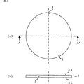
図1は、本発明のダミーウエハの一形態を示す模式図であって、(a)は上面図、(b)はA−A’断面図である。
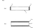
図2(a)、(b)は、それぞれ本発明のダミーウエハの他の形態を示す模式的断面図である。
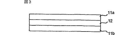
図3は、ウエハ基体の一形態を示す模式的断面図である。
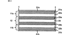
図4は、実施例1で製造したダミーウエハの模式的断面図である。
1:ウエハ基体、2a、2b:主表面、3:端面、、4:端面被覆層、5a、5b:主表面被覆層、11a、b:スキン層、12:コア層、21a、b:引張弾性率230GPaのPAN系炭素繊維を含むCFRP層、22a、b:引張弾性率800GPaのピッチ系炭素繊維を含むCFRP層、23a、b:ガラス繊維強化プラスチック層、24:引張弾性率600GPaのピッチ系炭素繊維を含むCFRP層、31a、b:炭素繊維クロス層。1A and 1B are schematic views showing an embodiment of a dummy wafer according to the present invention, in which FIG. 1A is a top view and FIG. 1B is a cross-sectional view along AA ′.
2A and 2B are schematic cross-sectional views showing other forms of the dummy wafer of the present invention, respectively.
FIG. 3 is a schematic cross-sectional view showing one embodiment of a wafer substrate.
4 is a schematic cross-sectional view of a dummy wafer manufactured in Example 1. FIG.
1: Wafer substrate, 2a, 2b: main surface, 3: end surface, 4: end surface coating layer, 5a, 5b: main surface coating layer, 11a, b: skin layer, 12: core layer, 21a, b: tensile elasticity CFRP layer containing PAN-based carbon fiber with a rate of 230 GPa, 22a, b: CFRP layer containing pitch-based carbon fiber with a tensile modulus of 800 GPa, 23a, b: Glass fiber-reinforced plastic layer, 24: Pitch-based carbon with a tensile modulus of 600 GPa CFRP layer containing fibers, 31a, b: carbon fiber cloth layer.
〔ダミーウエハ〕
本発明のダミーウエハの形状には特段の制限はないが、通常、実際の半導体製品に用いられるプライムウエハと同じ形状とされる。プライムウエハの形状については、例えば、SEMI(Semiconductor Equipment and Materials International)スタンダードに定められている。ダミーウエハの寸法についても同様である。
炭素繊維強化プラスチック(以下、CFRPという。)は軽量で割れにくく、平面精度を高くすることや歪みを少なくすることが容易であり、光センサにも反応しやすく、しかもシリコンなどに比べて安価である。本発明のダミーウエハは、このように優れたCFRPを含むため、これらの点において極めて優れたものである。また、CFRPは石英等のように透明ではないため、光センサーも容易に反応する。
〔CFRP中のマトリックス樹脂〕
CFRPは炭素繊維を主とする強化繊維にマトリックス樹脂を含浸してプリプレグとし、プリプレグを必要に応じて積層したのち、マトリックス樹脂を硬化させて得ることができる。
マトリックス樹脂としては熱硬化性樹脂、熱可塑性樹脂およびこれらの2以上の混合物が使用でき、特に熱硬化性樹脂が好ましく使用できる。
熱硬化性樹脂としてはエポキシ樹脂、アラミド樹脂、ビスマレイミド樹脂、フェノール樹脂、フラン樹脂、尿素樹脂、不飽和ポリエステル樹脂、エポキシアクリレート樹脂、ジアリルフタレート樹脂、ビニルエステル樹脂、熱硬化性ポリイミド樹脂、メラミン樹脂等の熱硬化性樹脂を使用することができ、エポキシ樹脂が好ましい。
熱可塑性樹脂としては、ナイロン樹脂、液晶性芳香族ポリアミド樹脂、ポリエステル樹脂、液晶性芳香族ポリエステル樹脂、ポリプロピレン樹脂、ポリエーテルスルホン樹脂、ポリフェニレンサルファイド樹脂、ポリエーテルエーテルケトン樹脂、ポリスルホン樹脂、ポリ塩化ビニル樹脂、ビニロン樹脂、アラミド樹脂、フッ素樹脂等の樹脂を使用することができる。
〔マトリックス樹脂の物性〕
マトリックス樹脂は、25℃で好ましくは5,000ポイズ〜1,000,000ポイズ、より好ましくは10,000ポイズ〜1,000,000ポイズ、さらに好ましくは50,000ポイズ〜150,000ポイズの、50℃では好ましくは1,000ポイズ〜30,000ポイズ、より好ましくは1,000ポイズ〜10,000ポイズの粘度を有している。CFRP製造用のマトリックス樹脂の25℃での粘度を1,000,000ポイズ以下とすることにより、プリプレグが固くなってタックネスが低下することを優れて防止でき、5,000ポイズ以上とすることにより、タックネスが強くプリプレグ積層時に一度貼り合わせたプリプレグが剥がれにくくなってプリプレグの積層の修正などが難しくなることを優れて防止できる。また、50℃での粘度を1,000ポイズ以上とすることにより、樹脂の含浸性が良く、成形時のレジンフロー性が大きくなることを優れて防止でき、50℃での粘度を30,000ポイズ以下とすることにより、成形時のレジンフロー性が小さく樹脂の含浸性が劣ることを優れて防止できる。
〔プリプレグ中のマトリックス樹脂の量〕
プリプレグ中に含まれるマトリックス樹脂の量は、これにフィラーなどの任意成分が含まれているか、含まれていないかに拘らず、強化繊維とマトリックス樹脂の総量に対して好ましくは20質量%〜50質量%、より好ましくは25質量%〜45質量%の範囲で選ばれる。
〔耐熱性エポキシ樹脂組成物〕
硬化剤としてジアミノジフェニルスルホンを使用したエポキシ樹脂組成物をマトリックス樹脂として使用すれば、ダミーウエハの耐熱温度を230℃まで高めることができ、極めて良好なコンポジット物性と優れた耐熱性及び実質的にアウトガスのないダミーウェハを製造することができる。アウトガスは樹脂から外部に出てくるガスであり、これが半導体製造プロセスの汚染源となる場合がある。
上記エポキシ樹脂組成物に用いるエポキシ樹脂としては各種のエポキシ樹脂を使用することができるが、ビスフェノールA型エポキシ樹脂、フェノールノボラック型エポキシ樹脂、グリシジルアミン型エポキシ樹脂、ビスフェノールF型エポキシ樹脂から選ばれる1あるいは2以上の組み合わせとジアミノジフェニルスルホンからなるエポキシ樹脂組成物が好ましい。
ビスフェノールA型エポキシ樹脂としては、20℃で液状のビスフェノールA型エポキシ樹脂が好ましく使用される。ここで、20℃で液状とは当該温度で樹脂の粘度が1ポイズ〜1000ポイズ、好ましくは10ポイズ〜500ポイズの範囲にあることをいう。20℃で液状のビスフェノールA型エポキシ樹脂の具体例を示せば、エポトートYD128、YD134(以上東都化成社製)、エピコート828、834(以上油化シェルエポキシ社製)等の商品名ないしは商品番号で市販されているビスフェノールA型エポキシ樹脂を挙げることができる。エポキシ樹脂組成物におけるビスフェノールA型エポキシ樹脂の含有量は、全エポキシ樹脂100質量部に対して、好ましくは20質量部〜40質量部、より好ましくは25質量部〜35質量部の範囲で選ばれる。ビスフェノールA型エポキシ樹脂の含有量を20質量部以上とすることにより、エポキシ樹脂組成物の粘度が高くなって炭素繊維等の繊維束への含浸が難しくなることを良好に防止でき、中間材であるプリプレグにしたときのタック(粘着性)が低下することを良好に防止できる。一方、40質量部以下とすることにより、プリプレグにしたときのタックが強くなってその取り扱いが難しくなることを良好に防止でき、複合材料にしたときのコンポジット物性が低下し、耐熱性、耐湿性が低下することを良好に防止できる。
フェノールノボラック型エポキシ樹脂としては、52℃での粘度が10ポイズ〜3000ポイズ、より好ましくは10ポイズ〜2000ポイズのフェノールノボラック型エポキシ樹脂が好ましく使用される。使用可能な樹脂の具体例としては、エピコート152、154(以上油化シェルエポキシ社製)、DEN431、438、439(以上ダウケミカル社製)、フェノトートYP50、YDPN638(東都化成社製)等の商品名ないしは商品番号で市販されているフェノールノボラック型エポキシ樹脂を挙げることができる。これを使用することで複合材料のコンポジット物性、耐熱性及び耐湿性を向上させることができる。フェノールノボラック型エポキシ樹脂のエポキシ樹脂組成物中の含有量は、全エポキシ樹脂100質量部に対して、好ましくは40質量部〜60質量部、より好ましくは45質量部〜55質量部の範囲で選択される。
グリシジルアミン型エポキシ樹脂としては、4官能グリシジルアミン型エポキシ樹脂が好ましく、より詳しくはテトラグリシジルジアミノジフェニルメタンが好ましい。この種の4官能グリシジルアミン型エポキシ樹脂は、エポトートYH434(東都化成社製)、ELM434(住友化学工業社製)、エピコート604(油化シェルエポキシ)等の商品名ないしは商品番号で市販されている。この成分をエポキシ樹脂組成物中に配合することによってCFRPのコンポジット物性、耐熱性及び耐湿性を一段と向上させることができる。この含有量は、全エポキシ樹脂100質量部に対して、好ましくは10質量部〜30質量部、より好ましくは15質量部〜25質量部の範囲で選ばれる。
ビスフェノールF型エポキシ樹脂は、ビスフェノールFとエピクロロヒドリンとの縮合反応生成物である。エポキシ当量が155〜190の範囲にあり、25℃での粘度が4.0ポイズ〜4.5ポイズの範囲にあるビスフェノールF型エポキシ樹脂を使用することが好ましい。市販品では、エピコート807(油化シェルエポキシ社製)、エポトートYDF170(東都化成社製)、エピクロン830(大日本インキ化学工業社製)等がある。エポキシ樹脂組成物にビスフェノールF型エポキシ樹脂を配合する場合、その配合量は全エポキシ樹脂100質量部に対して、好ましくは50質量部以下、より好ましくは40質量部以下、さらに好ましくは15質量部以下の範囲から選ぶ。この含有量を50質量部以下とすることにより、最終的に得られるエポキシ樹脂組成物の粘度調整を容易にすることができ、適正なプリプレグの製造を容易にすることができ、硬化物のガラス転移温度が低下することを防止して優れた耐熱性を得ることができる。
さらに他の成分としてフェノキシ樹脂を使用することができ、典型的には下式で示されるフェノキシ樹脂又はこれをエポキシ変性したものが使用できる。フェノキシ樹脂の具体例としては、YP50(東都化成社製)、PKHH(フェノキシアソシエイツ社製)などの商品名ないしは商品番号で市販されているものを用いることができる。その含有量は、全エポキシ樹脂100質量部に対して、好ましくは5質量部〜20質量部の範囲、より好ましくは7質量部〜18質量部の範囲で選ぶことができる。
ジアミノジフェニルスルホンとしては、4、4’−ジアミノジフェニルスルホンと3、3’−ジアミノジフェニルスルホンが使用でき、4、4’−ジアミノジフェニルスルホンが好ましい。これは硬化剤として機能する成分であって、これには例えばセイカキュア−S(商品名、和歌山化成工業社製)を好適に使用することができる。このセイカキュア−Sは平均粒径8μm〜9μmの粉末である。使用量は、上記エポキシ樹脂組成物中に全エポキシ樹脂100質量部に対して、好ましくは30質量部〜50質量部の範囲で、より好ましくは35質量部〜45質量部の範囲で選ばれる。30質量部以上とすることにより、CFRPにしたときの物性、耐熱性、耐湿性が優れ、50質量部以下とすることによりエポキシ樹脂組成物を繊維束へ容易に含浸することができる。
ジアミノジフェニルスルホンは、直径0.01μm〜10μmの微粒子で上記エポキシ樹脂組成物中に分散していることが好ましい。この分散には、ニーダー、3本ロールなどの適当な手段を用いて混練する公知の分散方法を採用できる。
上記エボキシ樹脂組成物には、必要に応じ、その性能を損なわない範囲で上記した以外のエポキシ樹脂、靭性付与剤、フィラー、着色剤等を配合することができる。フィラーとしては、例えば、マイカ、アルミナ、タルク、微粉状シリカ、ウォラストナイト、セピオライト、塩基性硫酸マグネシウム、亜鉛末、アルミニウム粉、クレー、炭酸カルシウム、二酸化チタン、硫酸カルシウム、硫酸バリウム、カーボンブラックなどの無機充填剤、テフロン粉末、ポリエチレン粉末、ポリアミド粉末、EVA(エチレン酢酸ビニル共重合体)粉末などの有機充填剤がある。フィラーを添加する場合、フィラーの添加量は上記エボキシ樹脂組成物中に全エポキシ樹脂100質量部に対して、通常5質量部〜60質量部程度とすることができる。
使用可能な着色剤としては有機顔料ではアゾ顔料、フタロシアニン系顔料、キナクリドン系顔料、アンスラキノン系顔料等、無機顔料では二酸化チタン、黄鉛、コバルトバイオレット、ベンガラ等が例として挙げられる。
また、上記エポキシ樹脂組成物には、上記したジアミノジフェニルスルホン以外の硬化剤ないしは硬化促進剤を、必要に応じて配合することができる。その硬化剤としては、ジアミノジフェニルスルホン、ジアミノジエチルベンゼン等が例示でき、硬化促進剤としては、三フッ化ホウ素モノエチルアミン錯体、三塩化ホウ素モノエチルアミン錯体等が例示できる。
〔CFRP中の炭素繊維〕
CFRPに含まれる炭素繊維としては、ピッチ系炭素繊維やポリアクリロニトリル(PAN)系炭素繊維を用いることができる。シリコンウエハと同等以上の引張弾性率とする観点から、使用する炭素繊維の引張弾性率は400GPa以上が好ましく、500GPa以上がより好ましく、600GPa以上がさらに好ましい。また、ハンドリングや成形性の観点から、使用する炭素繊維の引張弾性率は1000GPa以下が好ましく、900GPa以下がより好ましく、800GPa以下がさらに好ましい。このような引張弾性率を有する炭素繊維としてピッチ系炭素繊維を好適に用いることができる。ピッチ系炭素繊維を用いることはコストの観点からも好ましい。なお、ピッチ系炭素繊維はピッチから得られる炭素繊維であり、PAN系炭素繊維はポリアクリロニトリルから得られる炭素繊維である。
CFRPの強化繊維として炭素繊維のみを用いることもできるが、炭素繊維をガラス繊維、アラミド繊維、ステンレス繊維、銅繊維、ニッケル繊維、チタン繊維、タングステン繊維、炭化ケイ素繊維、アルミナ繊維、炭化チタン繊維、窒化ホウ素繊維その他の繊維と組み合わせて用いることもできる。
上記した強化繊維の形態としては特に限定されず、一次元強化、二次元強化、三次元強化、ランダム強化等目的に応じて適宜選択することができる。例えば強化繊維を短繊維、織布、不織布、一方向材、二次元織物、三次元織物等、より具体的にはフェルト、マット、組布、ワリフ、疑似等方材、平織、朱子織、綾織、模紗織り、からみ織等の材料を積層して使用することもできる。
〔CFRPの製造〕
CFRPは通常知られた方法により製造できる。例えば前記のような形態に加工した強化繊維にマトリックス樹脂として熱硬化性樹脂を含浸してプリプレグとし、さらにこれらを積層して硬化および成形すなわち硬化成形することによりCFRPとすることができる。中でも強化繊維に一方向材を使用したプリプレグを、0°、±45°、90°等の組で適宜配向させて積層し、所定の弾性率を有する成形物を得ることが好適な製造方法である。
前記強化繊維にマトリックス樹脂を含浸させる方法としては公知の方法を適宜採用できるが、マトリックス樹脂として熱硬化性樹脂を用いる場合、樹脂を通常60℃〜90℃に加温して強化繊維に含浸させる、いわゆるホットメルト法を好ましく採用することができる。製造されたプリプレグ中のマトリックス樹脂の含量は強化繊維とマトリックス樹脂の総量に対して好ましくは20質量%〜50質量%、より好ましくは25質量%〜45質量%の範囲である。
マトリックス樹脂には所望に応じてフィラーを添加することができ、該フィラーとしてはマイカ、アルミナ、タルク、微粉状シリカ、ウォラストナイト、セピオライト、塩基性硫酸マグネシウム、炭酸カルシウム、ポリテトラフルオロエチレン粉末、亜鉛末、アルミニウム粉、有機微粒子、すなわちアクリル微粒子、エポキシ樹脂微粒子、ポリアミド微粒子、ポリウレタン微粒子等が挙げられる。
プレプレグは最終的にCFRPに成形される。その成形法としてはオートクレーブ成形法、シートローリング成形法などが使用できる。例えば、マトリックス樹脂に熱硬化性樹脂を使用する場合、プリプレグをダミーウェハに適した形状になるように積層して、オートクレーブ中または加圧プレス等により通常110℃〜150℃で30分〜3時間、加熱硬化させることによりCFRPとすることができる。得られたCFRPは品質が安定で、ボイドの少ないものを得ることができる。
上記エポキシ樹脂組成物を使用した場合の好ましい成形条件は、加熱温度150℃〜200℃、硬化時間30分〜2時間である。
ダミーウェハは精密な加工精度を必要とするので、得られたCFRPをダミーウェハに適した形状にさらに機械加工などにより加工することができる。
〔ダミーウエハの構造〕
以下、CFRPを含むダミーウエハの形態について図面を参照しつつ詳しく述べる。
図1は、本発明のダミーウエハの一形態を示す模式図であって、図1(a)は上面図、同(b)はA−A’断面図である。このダミーウエハはウエハ基体1からなる。ウエハ基体は板状、特には円板状であり、上面側の主表面2a、下面側の主表面2b、および端面3を有し、また位置あわせのための切り欠きであるノッチ4を有する。
ダミーウエハはウエハ基体のみからなる必要はなく、例えば、ウエハ基体上に発塵防止や引っ掻き傷防止等、所望の目的に応じた被覆層を有することもできる。図2(a)に示すダミーウエハは、ウエハ基体1の端面に、端面を被覆する端面被覆層4を有する。図2(b)に示すダミーウエハは、ウエハ基体1の主表面に、それぞれの主表面を被覆する主表面被覆層5aおよび5bを有する。ウエハ基体1上に一方の主表面被覆層(5aまたは5b)のみを有してもよいし、一方もしくは両方の主表面被覆層に加えて端面被覆層を有するなど、様々なバリエーションがあり得る。被覆層は例えば樹脂で形成することができる。またノッチを機械加工によって設けた場合、その加工面に被覆層を設けることもできる。
〔ウエハ基体〕
ウエハ基体は、一つの板状炭素繊維強化プラスチック(CFRP)からなることができ、また例えば、目的とするウエハ基体と同形でただし厚さが薄い、複数のCFRPからなる層(以下、CFRPからなる層をCFRP層という。)が接合されて厚さ方向に積層した板状積層体であってもよい。さらに例えばウエハ基体が、CFRP層に加えて、ウエハ基体と同形でただし厚さが薄い他の層を有することもできる。他の層としては、例えば樹脂からなる層や、炭素繊維を主な強化繊維としない繊維強化プラスチックからなる層を挙げることができる。
複数のCFRP層を有するウエハ基体は、全て同じ形状、寸法、材料のCFRP層が、同じ配向性をもって積層されたものであってもよいが、必ずしもこのような構成である必要はない。複数のCFRP層が、厚さ、材料および配向性のうちの一つ以上において異なるものであってもよい。
例えば、ウエハ基体が、同じ形状、寸法、材料のCFRP層が、異なる配向性をもって積層されたものであってもよい。CFRPは炭素繊維の配向方向にはたわみにくく、それと直交する方向にはたわみやすいという性質を有する。複数のCFRPの配向性が異なっていると、これらが積層したウエハ基体のたわみの等方性が向上するという点で好ましい。
また例えばウエハ基体が、炭素繊維が一方向に配向した一方向プリプレグの硬化成形物からなる炭素繊維強化プラスチックからなる層である一次元強化CFRP層を複数有し、複数の一次元強化CFRP層のうちの、一部の層の炭素繊維の引張弾性率が、他の層の炭素繊維の引張弾性率よりも高い形態がある。
図3に、二つの主表面側にそれぞれ位置するスキン層11aおよび11bと、これらに挟まれるコア層12を有するウエハ基体を模式的に示す。
図3に示されるようなウエハ基体において、ダミーウエハの曲げに対する強度にはコア層よりスキン層、しかも最外層の特性が重要である。
実質的に均一な曲げ剛性を得る(ダミーウェハは薄いものほど曲げ剛性の弱い部分から撓んでしまいやすいから、均一な曲げ特性は薄いもの程重要な特性になる)には積層する炭素繊維の弾性率を異なるものにすることが更に好ましく、スキン層の最外層(その強化方向すなわち炭素繊維の配向方向をダミーウエハの基準方向とする)には中または高弾性率の炭素繊維を使用し、その内側層(この層を基準方向と異なる方向、例えば90°に配向させるとさらによい)には最外層よりも高弾性率の炭素繊維を使用することが好ましい。なお、本明細書中、角度表示については反時計回りを+方向とする。
ウエハ基体の好ましい形態例として、ウエハ基体が、それぞれ主表面側に位置する二つのスキン層と、該二つのスキン層の間に位置するコア層とを有し、
該二つのスキン層は、いずれも、前記一次元強化CFRP層を複数有し、
該二つのスキン層のそれぞれにおいて最も主表面側に位置する一次元強化CFRP層である二つの最外CFRP層の一方の炭素繊維の配向方向を基準方向としたとき、他方の最外CFRP層の炭素繊維の配向方向は該基準方向に対して−20°〜+20°の角度範囲にあり、
該二つの最外CFRP層中の炭素繊維の引張弾性率はいずれも200GPa〜600GPaであり、
該二つのスキン層は、いずれも、該基準方向に対して+75°〜+90°の角度範囲に配向し且つ引張弾性率が400GPa〜1000GPaであっていずれの最外CFRP層の炭素繊維の引張弾性率よりも高い炭素繊維を含有する一次元強化CFRP層および/または該基準方向に対して−75°〜−90°の角度範囲に配向し且つ引張弾性率が400GPa〜1000GPaであっていずれの最外CFRP層の炭素繊維の引張弾性率よりも高い炭素繊維を含有する一次元強化CFRP層を有し、
該コア層は、該基準方向に対して+30°〜+60°の角度範囲に配向し且つ引張弾性率が400GPa〜1000GPaである炭素繊維を含有する一次元強化CFRP層および/または−30°〜−60°の角度範囲に配向し且つ引張弾性率が400GPa〜1000GPaである炭素繊維を含有する一次元強化CFRP層を有するダミーウエハが挙げられる。
曲げ剛性は、レイヤーの曲げ弾性率に対して中立軸からの距離の3乗とレイヤー厚みを乗じたものとなるので、最外層は中立軸からの距離の影響を最も受けやすいため、好ましくは、該二つのスキン層のそれぞれの厚さは、該二つのスキン層とコア層の合計の厚さの10%〜45%である。
他の好ましい形態として、炭素繊維強化プラスチックを含むウエハ基体を有するダミーウエハであって、
前記ウェハ基体が、それぞれ主表面側に位置する二つのスキン層と、該二つのスキン層の間に位置するコア層とを有し、
該二つのスキン層は、いずれも、炭素繊維が一方向に配向した一方向プリプレグの硬化成形物からなる炭素繊維強化プラスチックからなる層である一次元強化CFRP層を複数有し、
該二つのスキン層のそれぞれにおいて最も主表面側に位置する一次元強化CFRP層である二つの最外CFRP層の一方の炭素繊維の配向方向を基準方向としたとき、他方の最外CFRP層の炭素繊維の配向方向は該基準方向に対して−20°〜+20°の角度範囲にあり、
該二つの最外CFRP層の炭素繊維の引張弾性率はいずれも200GPa〜600GPaであり、
該二つのスキン層は、いずれも、該基準方向に対して+75°〜+90°の角度範囲に配向し且つ引張弾性率がそのスキン層に含まれる最外CFRP層の炭素繊維の引張弾性率の1.5倍〜3.0倍である炭素繊維を含有する一次元強化CFRP層および/または該基準方向に対して−75°〜−90°の角度範囲に配向し且つ引張弾性率がそのスキン層に含まれる最外CFRP層の炭素繊維の引張弾性率の1.5倍〜3.0倍である炭素繊維を含有する一次元強化CFRP層を有し、該コア層が、該基準方向に対して−20°〜+20°の角度範囲に配向し引張弾性率が200GPa〜400GPaである炭素繊維を含有する一次元強化CFRP層を有するとともに、該基準方向に対して+75°〜+90°の角度範囲に配向し引張弾性率が200GPa〜400GPaである炭素繊維を含有する一次元強化CFRP層および/または該基準方向に対して−75°〜−90°の角度範囲に配向し引張弾性率が200GPa〜400GPaである炭素繊維を含有する一次元強化CFRP層を有するダミーウエハが挙げられる。
このダミーウエハにおいて、前記二つのスキン層の少なくとも一方が、更に、前記基準方向に対して+30°〜+60°の角度範囲に配向し且つ引張弾性率がそのスキン層に含まれる最外CFRP層の炭素繊維の引張弾性率の1.5倍〜3.0倍である炭素繊維を含有する一次元強化CFRP層および/または前記基準方向に対して−30°〜−60°の角度範囲に配向し且つ引張弾性率がそのスキン層に含まれる最外CFRP層の炭素繊維の引張弾性率の1.5倍〜3.0倍である炭素繊維を含有する一次元強化CFRP層を有することが好ましい。
上記各形態のダミーウエハにおいて、機械加工時に表層の剥離を防止する観点から、さらに、それぞれの主表面に炭素繊維クロス層を有することが好ましい。
〔ウエハ基体の製造〕
ウエハ基体は、例えば、板状のCRFPを円状等所望の形状に機械加工することによって製造することができる。あるいは必要に応じて複数の板状CFRPを接合して所望の厚さの一体化された板状部材とし、これを所望の形状に機械加工することにより製造することができる。1以上の板状CFRPと、他の材料から成る板状部材を組み合わせて接合し、一体化された板状部材とし、これを所望の形状に機械加工することにより製造することができる。
〔SEMIスタンダード〕
シリコンウエハについては、例えば、SEMI M1.14−95に、300mm〜400mm鏡面単結晶シリコンウエハのガイドラインが定められている。このガイドラインに記載される、寸法及び許容誤差に対する要求条件を表1にまとめる。
このようなシリコンウエハの代わりに用いられるダミーウエハは、形状、寸法をシリコンウエハと同じとすべきであるが、表1に示されるように、その厚さは0.8mmと薄く、場合によっては0.5mmと更に薄いものを要求されている。このように薄いダミーウエハを製造するためには、薄いプリプレグシートを多数積層することが好ましい。複数のプリプレグを用いることで、ダミーウエハ設計上の自由度が得られ、例えばSEMIスタンダードの要求寸法・許容誤差等に適合するダミーウエハを容易に得ることができるからである。特には、複数のプリプレグシートの配向性を変えて、疑似等方積層(例えば0/90/45°の組合せ)し、それぞれの強化繊維の弾性率も適宜変更することがより好ましい。CFRPの曲げ剛性の異方性を解消できるからである。このような目的のため、厚さ100μm以下のプリプレグシートを用いて、CFRPを製造することが好ましい。CFRP製造に用いるプリプレグが、全て厚さ30μm〜100μmのプリプレグシートであることがより好ましい。

ウェハ基体が加工面を有する場合は、極性溶剤に対して耐性を有しかつ70℃以下の低温で硬化する樹脂(以下、被覆樹脂という。)で加工面が被覆されていることが好ましい。ここでいう加工面とは、機械加工等の加工によりCFRP中の炭素繊維が露出した部分をいい、具体的には切断面、研磨面、R加工面、穴加工面、薄加工面等である。例えば、ウエハ基体の端面が機械加工によって形成された加工面である場合、図2(a)のように端面に被覆層を設けることが好ましい。加工面を被覆することにより、加工面からの炭素による汚染を防止して、CFRP製ダミーウェハが本来有している軽量性および高剛性を活かしつつ、精密機器材料を汚染しにくく処理したダミーウェハを得ることができる。またこの被覆は、引っ掻き傷防止など、端面保護の効果もある。
被覆樹脂としては、例えば、アクリル樹脂、紫外線硬化型エポキシ樹脂、室温−中温硬化型エポキシ樹脂、湿気硬化型シリコーン樹脂等あるいはこれらから選ばれる2種以上の樹脂の混合物が挙げられる。
例えば、これら樹脂から選ばれる2種類の樹脂の混合質量比は、1:0.05〜0.05:1が好ましい。
樹脂が極性溶剤に対して耐性があるとは、極性溶剤を含ませた布で樹脂塗布面を拭いても容易に塗布面が溶けたり、膨潤したり、べたついたりせず、ダミーウェハから炭素繊維起源の炭素微粒子等のゴミや塵が実質的に飛散しないことを意味し、更に樹脂塗布面の拭き取りに使用した布が炭素微粒子等で実質的に汚染されないことをいう。
極性溶剤とは、アセトン系あるいはアルコール系の溶剤等であり、例えばアセトン、ジエチルケトン、メチルエチルケトン、メタノール、エタノール、イソプロピルアルコールおよびこれらの混合物等をいう。
前記アクリル樹脂としては、ポリエステルアクリレート、ウレタンアクリレート、ポリエーテルアクリレート、エポキシアクリレート、ポリブタジエンアクリレート、シリコーンアクリレート、アクリルアクリレートおよびこれらの混合物等がある。
これら被覆樹脂に、室温硬化のための過酸化物または紫外線硬化のための触媒を添加して、室温または紫外線照射により樹脂を硬化することができる。
室温−中温硬化型エポキシ樹脂とは、通常10℃〜90℃、好ましくは20℃〜80℃で硬化するエポキシ樹脂である。90℃以下で硬化すればCFRP部材の熱変形を防止することができる。前記室温−中温硬化型エポキシ樹脂としては、脂環式アミンおよび/あるいは芳香族アミンとエポキシ樹脂とのエポキシド反応物によるものを好ましく用いることができる。
前記紫外線硬化型エポキシ樹脂としては、例えば液状のビスフェノール型エポキシ樹脂、脂環式エポキシ樹脂あるいはこれらの混合物等を用いることができる。芳香族ジアゾニウム塩、芳香族ヨードニウム塩、芳香族スルホニウム塩、メタロセン化合物およびこれらの混合物等を、硬化触媒として紫外線硬化型エポキシ樹脂に添加できる。
前記シリコーン樹脂としては、アルキド変性型シリコーン樹脂、エポキシ変性型シリコーン樹脂、湿気硬化アルコール型シリコーン樹脂、湿気硬化オキシム型シリコーン樹脂、付加反応型シリコーン樹脂が使用できるが、湿気硬化アルコール型シリコーン樹脂、湿気硬化オキシム型シリコーン樹脂が好ましい。
前記湿気硬化アルコール型シリコーン樹脂としては、例えばSR2410、SR2406、SR2420、SR2416(各々商品名、東レ・ダウコーニング・シリコーン(株)製)、KE4895(商品名、信越化学(株)製)が使用できる。
前記湿気硬化アルコール型シリコーン樹脂の硬化触媒としては、ジブチル錫ジアセテート、ジブチル錫ジラウレートおよびこれらの混合物等が使用される。
前記湿気硬化オキシム型シリコーン樹脂としては、例えばSR2405、SR2411(各々商品名、東レ・ダウコーニング・シリコーン(株)製)、KE445(商品名、信越化学(株)製)が使用できる。
前記湿気硬化オキシム型シリコーン樹脂の硬化触媒としては、湿気硬化アルコール型シリコーン樹脂と同様にジブチル錫ジアセテート、ジブチル錫ジラウレートおよびこれらの混合物等が使用できる。
被覆方法としては、溶剤で5質量部〜60質量部に希釈した被覆樹脂を、ダミーウェハの加工面に塗布して、塗布された該樹脂を70℃以下で加熱硬化させる方法が好ましく用いられる。この方法により、極性溶剤に対して耐性を有しかつ70℃以下の低温で硬化する樹脂(被覆樹脂)で加工面が被覆されているダミーウェハが得られる。溶剤で希釈した被覆樹脂の濃度を5質量部以上とすることにより、希釈被覆樹脂を加工面に塗布して得られる被膜が薄くなるのを防止でき、60質量部以下とすることにより、塗布された被覆樹脂が硬化後に部材表面に塗りムラによる凹凸が生じることを優れて防止できる。
被覆樹脂の塗布方法は特に限定されず、どのような方法も適宜使用できるが、ダミーウェハの加工面に塗布被覆できればよく、刷毛塗り、スプレー吹き付け、ロール塗り等を採用できる。
溶剤で希釈した被覆樹脂を塗布・硬化して得られる被覆層の厚さは、例えば5μm〜30μmであることができる。30μm以下とすることにより、乾燥に長時間かかることを防止でき、また、液だれやムラを優れて防止できる。一方5μm以上とすることにより、被覆の効果が良好に得られる。
前記被覆樹脂の硬化温度は、20℃〜70℃が好ましく、70℃以下で硬化することにより、硬化の際、ダミーウェハに熱による反りや変形が生じることを優れて防止できる。
実施例1 ダミーウェハの積層成形
以下に示す手順で、図4に示すダミーウエハを作成した。
(1)複合材料用樹脂組成物の製造
ビスフェノールA型エポキシ樹脂としてエポトートYD128(商品名、東都化成社製)30質量部、フェノールノボラック型エポキシ樹脂としてエポトートYDPN638(商品名、東都化成社製)50質量部、フェノキシ樹脂としてフェノトートYP50(商品名、東都化成社製)10質量部を200℃で1.5時間混合し、これを90℃に冷却した。これにグリシジルアミン型エポキシ樹脂であるエポトートYH434(商品名、東都化成社製)20質量部と、硬化剤である4、4’−ジアミノジフェニルスルホン(DDS)(商品名:セイカキュア−S、和歌山化成工業社製)40質量部を真空脱気下に均一混合して耐熱性のエポキシ樹脂組成物を得た後、これを他の容器に移し替えて冷却した。
(2)スキン層の作製
引張弾性率800GPaのピッチ系炭素繊維を一方向に引き揃えて上記(1)で得たエポキシ樹脂組成物を含浸させて得た一方向プリプレグシート(単位面積当り繊維質量:70g/m2、樹脂含有量:38質量%、厚み0.067mm)を、その強化方向がダミーウェハの基準方向に対して90°方向となるように1枚と、引張弾性率230GPaのPAN系炭素繊維を一方向に引き揃えて上記(1)で得たエポキシ樹脂組成物に含浸させて得た一方向プリプレグシート(単位面積当り繊維質量:85g/m2、樹脂含有量:38質量%、厚み0.089mm)を1枚(その強化方向がダミーウエハの基準方向すなわち0°方向となる)積層して、オートクレーブにより硬化し、厚み0.156mmのスキン層を作製した。なおピッチ系炭素繊維を用いた前者のプリプレグの硬化成形物のスキン層における体積割合は43%とし、残りの57%はPAN系炭素繊維を用いた後者のプリプレグの硬化成形物とした。また、上記ピッチ系炭素繊維を含むプリプレグシートは、ダミーウェハ完成時にはピッチ系炭素繊維を含むCFRP層22aおよび22bとなり、上記PAN系炭素繊維を含むプリプレグシートは、PAN系炭素繊維を含むCFRP層21aおよび21bとなる(これらが最外CFRP層となる)。
(3)コア層の作製
引張弾性率600GPaのピッチ系炭素繊維を一方向に引き揃えて前記エポキシ樹脂組成物に含浸させて得た一方向プリプレグシート(単位面積当り繊維質量:50g/m2、樹脂含有量:38質量%、厚み0.048mm)、および直交する2方向にガラス繊維を有するガラス繊維織物に、上記(1)で得たエポキシ樹脂組成物を含浸させて得たガラス繊維織物プリプレグシート(単位面積当り繊維質量:80g/m2、樹脂含有量:35質量%、厚み0.066mm)を使用し、最初に引張弾性率600GPaのピッチ系炭素繊維を有する一方向プリプレグシートをその強化方向がダミーウェハの基準方向に対して+45°となるように、次に上記引張弾性率600GPaのピッチ系炭素繊維を有する一方向プリプレグシートを、その強化方向がダミーウェハの基準方向に対して−45°となるように、それぞれ1枚ずつ積層した。さらにこの上に、上記ガラス繊維織物プリプレグシートを、その強化方向のひとつが、ダミーウェハの基準方向と一致するように、1枚積層した。最後にこの上に、上記引張弾性率600GPaのピッチ系炭素繊維を有する一方向プリプレグシートをその強化方向がダミーウェハの基準方向に対して−45°となるように、次に上記引張弾性率600GPaのピッチ系炭素繊維を有する一方向プリプレグシートを、その強化方向がダミーウェハの基準方向に対して+45°となるように、それぞれ1枚ずつ積層して、オートクレーブにより硬化し、厚み0.258mmのコア層を作製した。
なおピッチ系炭素繊維を用いた前者のプリプレグの硬化成形物のコア層における体積割合は74%とし、残りの26%はガラス繊維を用いた後者のプリプレグの硬化成形物とした。上記ピッチ系炭素繊維を含むプリプレグシートの積層体は、ダミーウェハ完成時にはピッチ系炭素繊維を含むCFRP層23aおよび23bとなり、ガラス繊維を含むプリプレグシートは、ガラス繊維を含むガラス繊維強化プラスチック層24となる。
(4)ウェハ基体の作製
上記スキン層を二つ用意し、これらの間に上記コア層を配置させて接合し、さらに両スキン層の表面に、それぞれ引張弾性率230GPaの炭素繊維の織物(朱子織、厚み0.1mm)を積層して炭素繊維クロス層を形成させて、厚み0.770mmのCFRP板を得た。このクロス層は完成時に炭素繊維クロス層31aおよび31bとなる。このCFRP板から機械加工により、直径300mmの円盤状のウェハ基体を得た。なお、二つのスキン層にそれぞれ存在する最外CFRP層の炭素繊維の配向方向は揃えた。
(5)加工面樹脂被覆処理
上記円板状CFRP板の加工面である端部を、エタノールをしみこませた無塵のクリーンクロス(ポリエステルニット)で拭った後、湿気硬化アルコール型シリコーンコーティング剤SR2410(商品名、東レ・ダウコーニング・シリコーン(株)製、樹脂濃度20質量部、溶剤:リグロイン)をハケを用いて前記加工面に塗布した。塗布されたシリコーンコーティング剤を乾燥後、さらに十分にコーティング剤の硬化を進めるため、50℃の乾燥炉中で1時間硬化させ、被覆層4を形成し、ダミーウエハを得た。
このとき、塗布面の塗りムラや凹凸はなかった。その後、エタノールをしみこませた無塵のクリーンクロス(ポリエステルニット)で塗布面を十分拭ったが、ダミーウェハ端部の被覆樹脂塗布面およびクリーンクロスの汚れは観察されなかった。
(6)機械的物性の試験(曲げ剛性の均一性)
上記ダミーウェハより、幅20mm×長さ80mm(×厚み0.770mm)の短冊状の試験片を切り出した。試験片の切り出し方向は、ダミーウェハの基準方向が上記試験片の長さ方向と一致するもの(0°試験片)、およびダミーウェハの基準方向に対して90°方向が上記試験片の長さ方向と一致するもの(90°試験片)の2種類とした。上記試験片を使用し、三点曲げ試験により曲げ弾性率を測定した。三点曲げ試験における支点間距離は60mmとした。
表2に示す通り、実施例1におけるダミーウェハは、基準方向および基準方向に対して90°に関する曲げ弾性率の差が小さい、等方性を有していた。
(7)平面精度の試験
上記ダミーウェハの中心、および中心から半径方向に30mm、60mm、90mm、120mm、および150mm(ダミーウェハの円周部)の円周について、15°毎に厚みを測定した。厚みの測定点数は、121点となった。最大厚みと最小厚みとの差は、0.02mmであり、実施例1のダミーウェハは均一な厚みを有していた。
(8)耐熱性
上記ダミーウエハに、ダミーウエハとほぼ同形状の黒鉛板(質量1kg)を載せた状態で、大気中200℃の電気炉に10分間投入した。その後、炉外に取り出し、10分間室温に放置して空冷するという熱衝撃試験を50サイクル行った。その結果、反りや剥離等の異状は全く生じなかった。また、試験前後の質量変化も全くなかった。
(9)アウトガス検査
真空度7.0×10⁻³Pa以下の条件により、アウトガス特性を評価した。実施例1のダミーウェハは、質量損失および再凝縮物質量比いずれに関しても良好なアウトガス特性を有していた。[Dummy wafer]
The shape of the dummy wafer of the present invention is not particularly limited, but is usually the same shape as the prime wafer used in an actual semiconductor product. The shape of the prime wafer is defined by, for example, SEMI (Semiconductor Equipment and Materials International) standard. The same applies to the dimensions of the dummy wafer.
Carbon fiber reinforced plastic (hereinafter referred to as CFRP) is lightweight and difficult to break, it is easy to increase planar accuracy and reduce distortion, it is easy to react to optical sensors, and is cheaper than silicon. is there. Since the dummy wafer of the present invention contains such excellent CFRP, it is extremely excellent in these respects. Further, since CFRP is not transparent like quartz or the like, the optical sensor easily reacts.
[Matrix resin in CFRP]
CFRP can be obtained by impregnating a reinforcing fiber mainly composed of carbon fiber with a matrix resin to form a prepreg, laminating the prepreg as necessary, and then curing the matrix resin.
As the matrix resin, a thermosetting resin, a thermoplastic resin, and a mixture of two or more thereof can be used, and in particular, a thermosetting resin can be preferably used.
As thermosetting resins, epoxy resins, aramid resins, bismaleimide resins, phenol resins, furan resins, urea resins, unsaturated polyester resins, epoxy acrylate resins, diallyl phthalate resins, vinyl ester resins, thermosetting polyimide resins, melamine resins Etc. can be used, and an epoxy resin is preferable.
As thermoplastic resins, nylon resin, liquid crystalline aromatic polyamide resin, polyester resin, liquid crystalline aromatic polyester resin, polypropylene resin, polyethersulfone resin, polyphenylene sulfide resin, polyetheretherketone resin, polysulfone resin, polyvinyl chloride Resins such as resin, vinylon resin, aramid resin, and fluororesin can be used.
[Physical properties of matrix resin]
The matrix resin is preferably from 5,000 poise to 1,000,000 poise, more preferably from 10,000 poise to 1,000,000 poise, and even more preferably from 50,000 poise to 150,000 poise at 25 ° C. At 50 ° C., it preferably has a viscosity of 1,000 poise to 30,000 poise, more preferably 1,000 poise to 10,000 poise. By setting the viscosity at 25 ° C. of the matrix resin for producing CFRP to 1,000,000 poises or less, it is possible to excellently prevent the prepreg from becoming hard and lowering the tackiness, and by setting it to 5,000 poises or more. Further, it is possible to excellently prevent the prepreg laminated once at the time of prepreg lamination from being strongly peeled off and difficult to correct the prepreg lamination. Further, by setting the viscosity at 50 ° C. to 1,000 poise or more, it is possible to excellently prevent the resin impregnation property and increase the resin flow property at the time of molding, and to increase the viscosity at 50 ° C. to 30,000. By making it poise or less, it is possible to excellently prevent the resin flowability during molding from being small and the resin impregnation property from being inferior.
[Amount of matrix resin in prepreg]
The amount of the matrix resin contained in the prepreg is preferably 20% by mass to 50% by mass with respect to the total amount of the reinforcing fibers and the matrix resin, regardless of whether or not an optional component such as a filler is contained therein. %, More preferably in the range of 25% by mass to 45% by mass.
[Heat-resistant epoxy resin composition]
If an epoxy resin composition using diaminodiphenylsulfone as a curing agent is used as a matrix resin, the heat resistance temperature of the dummy wafer can be increased to 230 ° C., and extremely good composite physical properties, excellent heat resistance and substantially outgassing can be achieved. No dummy wafer can be manufactured. Outgas is a gas coming out from the resin, and this may be a contamination source in the semiconductor manufacturing process.
Various epoxy resins can be used as the epoxy resin used in the epoxy resin composition, and one selected from bisphenol A type epoxy resins, phenol novolac type epoxy resins, glycidylamine type epoxy resins, and bisphenol F type epoxy resins. Or the epoxy resin composition which consists of a combination of 2 or more and diaminodiphenyl sulfone is preferable.
As the bisphenol A type epoxy resin, a bisphenol A type epoxy resin which is liquid at 20 ° C. is preferably used. Here, the liquid state at 20 ° C. means that the resin has a viscosity of 1 poise to 1000 poise, preferably 10 poise to 500 poise at that temperature. Specific examples of bisphenol A type epoxy resin that is liquid at 20 ° C. can be represented by product names or product numbers such as Epototo YD128, YD134 (manufactured by Tohto Kasei), Epicoat 828, 834 (manufactured by Yuka Shell Epoxy). A commercially available bisphenol A type epoxy resin can be mentioned. The content of the bisphenol A type epoxy resin in the epoxy resin composition is preferably 20 to 40 parts by mass, more preferably 25 to 35 parts by mass with respect to 100 parts by mass of the total epoxy resin. . By setting the content of the bisphenol A type epoxy resin to 20 parts by mass or more, it is possible to satisfactorily prevent the epoxy resin composition from increasing in viscosity and difficult to impregnate into fiber bundles such as carbon fibers. It can prevent well that the tack (adhesiveness) when making a certain prepreg falls. On the other hand, by setting it to 40 parts by mass or less, it is possible to satisfactorily prevent the tackiness when the prepreg is made and the handling thereof becomes difficult, and the composite physical properties when the composite material is made are deteriorated, and the heat resistance and moisture resistance are reduced. Can be prevented well.
As the phenol novolac type epoxy resin, a phenol novolac type epoxy resin having a viscosity at 52 ° C. of 10 poise to 3000 poise, more preferably 10 poise to 2000 poise is preferably used. Specific examples of resins that can be used include Epicoat 152, 154 (more from Yuka Shell Epoxy), DEN431, 438, 439 (more than Dow Chemical), Phenotote YP50, YDPN638 (manufactured by Toto Kasei), etc. A phenol novolak type epoxy resin marketed under the trade name or product number can be mentioned. By using this, the composite physical properties, heat resistance and moisture resistance of the composite material can be improved. The content of the phenol novolac-type epoxy resin in the epoxy resin composition is preferably 40 to 60 parts by mass, more preferably 45 to 55 parts by mass with respect to 100 parts by mass of all epoxy resins. Is done.
As the glycidylamine type epoxy resin, a tetrafunctional glycidylamine type epoxy resin is preferable, and more specifically, tetraglycidyldiaminodiphenylmethane is preferable. This kind of tetrafunctional glycidylamine type epoxy resin is commercially available under trade names or product numbers such as Epototo YH434 (manufactured by Tohto Kasei Co., Ltd.), ELM434 (manufactured by Sumitomo Chemical Co., Ltd.), Epicoat 604 (oiled shell epoxy). . By blending this component into the epoxy resin composition, the composite physical properties, heat resistance and moisture resistance of CFRP can be further improved. This content is preferably selected in the range of 10 to 30 parts by mass, more preferably 15 to 25 parts by mass with respect to 100 parts by mass of the total epoxy resin.
The bisphenol F type epoxy resin is a condensation reaction product of bisphenol F and epichlorohydrin. It is preferable to use a bisphenol F type epoxy resin having an epoxy equivalent in the range of 155 to 190 and a viscosity at 25 ° C. in the range of 4.0 poise to 4.5 poise. Commercially available products include Epicoat 807 (manufactured by Yuka Shell Epoxy Co., Ltd.), Epototo YDF170 (manufactured by Tohto Kasei Co., Ltd.), Epicron 830 (manufactured by Dainippon Ink & Chemicals, Inc.), and the like. When the bisphenol F type epoxy resin is blended in the epoxy resin composition, the blending amount is preferably 50 parts by mass or less, more preferably 40 parts by mass or less, and further preferably 15 parts by mass with respect to 100 parts by mass of the total epoxy resin. Select from the following range. By adjusting the content to 50 parts by mass or less, it is possible to easily adjust the viscosity of the finally obtained epoxy resin composition, to facilitate the production of an appropriate prepreg, and to obtain a cured glass. An excellent heat resistance can be obtained by preventing the transition temperature from decreasing.
Furthermore, a phenoxy resin can be used as another component, and typically, a phenoxy resin represented by the following formula or an epoxy-modified one thereof can be used. As specific examples of the phenoxy resin, those commercially available under trade names or product numbers such as YP50 (manufactured by Tohto Kasei) and PKHH (manufactured by Phenoxy Associates) can be used. The content can be selected in the range of preferably 5 to 20 parts by mass, more preferably 7 to 18 parts by mass with respect to 100 parts by mass of the total epoxy resin.
As diaminodiphenylsulfone, 4,4′-diaminodiphenylsulfone and 3,3′-diaminodiphenylsulfone can be used, and 4,4′-diaminodiphenylsulfone is preferred. This is a component that functions as a curing agent, and for this, SeikaCure-S (trade name, manufactured by Wakayama Kasei Kogyo Co., Ltd.) can be suitably used. This Seikacure-S is a powder having an average particle size of 8 μm to 9 μm. The amount used is preferably in the range of 30 to 50 parts by mass, more preferably in the range of 35 to 45 parts by mass with respect to 100 parts by mass of the total epoxy resin in the epoxy resin composition. By setting it as 30 mass parts or more, it is excellent in the physical property, heat resistance, and moisture resistance at the time of CFRP, and by making it 50 mass parts or less, an epoxy resin composition can be easily impregnated into a fiber bundle.
Diaminodiphenylsulfone is preferably dispersed in the epoxy resin composition as fine particles having a diameter of 0.01 μm to 10 μm. For this dispersion, a known dispersion method in which kneading is performed using an appropriate means such as a kneader or a three roll can be employed.
An epoxy resin other than those described above, a toughness imparting agent, a filler, a colorant, and the like can be blended with the ethoxy resin composition as necessary within a range not impairing its performance. Examples of fillers include mica, alumina, talc, finely divided silica, wollastonite, sepiolite, basic magnesium sulfate, zinc dust, aluminum powder, clay, calcium carbonate, titanium dioxide, calcium sulfate, barium sulfate, carbon black, etc. Inorganic fillers, Teflon powder, polyethylene powder, polyamide powder, EVA (ethylene vinyl acetate copolymer) powder, and other organic fillers. When adding a filler, the addition amount of a filler can be normally about 5 mass parts-60 mass parts with respect to 100 mass parts of all the epoxy resins in the said epoxy resin composition.
Examples of usable colorants include organic pigments such as azo pigments, phthalocyanine pigments, quinacridone pigments, and anthraquinone pigments, and inorganic pigments such as titanium dioxide, yellow lead, cobalt violet, and bengara.
Moreover, the epoxy resin composition can be blended with a curing agent or curing accelerator other than the above-mentioned diaminodiphenylsulfone, if necessary. Examples of the curing agent include diaminodiphenyl sulfone and diaminodiethylbenzene, and examples of the curing accelerator include boron trifluoride monoethylamine complex and boron trichloride monoethylamine complex.
[Carbon fiber in CFRP]
As the carbon fiber contained in CFRP, pitch-based carbon fiber or polyacrylonitrile (PAN) -based carbon fiber can be used. From the viewpoint of obtaining a tensile modulus equal to or higher than that of a silicon wafer, the tensile elastic modulus of the carbon fiber used is preferably 400 GPa or more, more preferably 500 GPa or more, and further preferably 600 GPa or more. Further, from the viewpoint of handling and moldability, the tensile elastic modulus of the carbon fiber to be used is preferably 1000 GPa or less, more preferably 900 GPa or less, and further preferably 800 GPa or less. Pitch-based carbon fibers can be suitably used as carbon fibers having such a tensile elastic modulus. The use of pitch-based carbon fibers is also preferable from the viewpoint of cost. The pitch-based carbon fiber is a carbon fiber obtained from pitch, and the PAN-based carbon fiber is a carbon fiber obtained from polyacrylonitrile.
Although only carbon fiber can be used as CFRP reinforcing fiber, carbon fiber is glass fiber, aramid fiber, stainless steel fiber, copper fiber, nickel fiber, titanium fiber, tungsten fiber, silicon carbide fiber, alumina fiber, titanium carbide fiber, It can also be used in combination with boron nitride fibers or other fibers.
The form of the above-described reinforcing fiber is not particularly limited, and can be appropriately selected according to the purpose such as one-dimensional reinforcement, two-dimensional reinforcement, three-dimensional reinforcement, and random reinforcement. For example, short fibers, woven fabrics, non-woven fabrics, unidirectional materials, two-dimensional woven fabrics, three-dimensional woven fabrics, etc. More specifically, felts, mats, braided fabrics, walliffs, pseudo-isotropic materials, plain weaves, satin weaves, twills In addition, materials such as imitation weave and leash weave can be laminated and used.
[Manufacturing CFRP]
CFRP can be produced by a generally known method. For example, a CFRP can be obtained by impregnating a reinforcing fiber processed into the above-mentioned form with a thermosetting resin as a matrix resin to form a prepreg, and further laminating and curing and molding, that is, curing molding. In particular, a prepreg using a unidirectional material for reinforcing fibers is suitably oriented in a set of 0 °, ± 45 °, 90 °, etc. and laminated to obtain a molded product having a predetermined elastic modulus. is there.
As a method of impregnating the reinforcing fiber with the matrix resin, a known method can be appropriately adopted. However, when a thermosetting resin is used as the matrix resin, the resin is usually heated to 60 ° C. to 90 ° C. to impregnate the reinforcing fiber. The so-called hot melt method can be preferably employed. The content of the matrix resin in the produced prepreg is preferably 20% by mass to 50% by mass, more preferably 25% by mass to 45% by mass, based on the total amount of the reinforcing fibers and the matrix resin.
Fillers can be added to the matrix resin as desired, such as mica, alumina, talc, finely divided silica, wollastonite, sepiolite, basic magnesium sulfate, calcium carbonate, polytetrafluoroethylene powder, Examples thereof include zinc dust, aluminum powder, organic fine particles, that is, acrylic fine particles, epoxy resin fine particles, polyamide fine particles, polyurethane fine particles, and the like.
The prepreg is finally formed into CFRP. As the molding method, an autoclave molding method, a sheet rolling molding method, or the like can be used. For example, when a thermosetting resin is used for the matrix resin, the prepreg is laminated so as to have a shape suitable for a dummy wafer, and usually in an autoclave or a pressure press at 110 ° C. to 150 ° C. for 30 minutes to 3 hours, CFRP can be obtained by heat curing. The obtained CFRP is stable in quality and can be obtained with less voids.
Preferred molding conditions when the above epoxy resin composition is used are a heating temperature of 150 ° C. to 200 ° C. and a curing time of 30 minutes to 2 hours.
Since the dummy wafer requires precise processing accuracy, the obtained CFRP can be further processed by machining or the like into a shape suitable for the dummy wafer.
[Dummy wafer structure]
Hereinafter, the form of the dummy wafer including CFRP will be described in detail with reference to the drawings.
1A and 1B are schematic views showing an embodiment of a dummy wafer according to the present invention, in which FIG. 1A is a top view and FIG. 1B is a cross-sectional view along AA ′. This dummy wafer comprises a
The dummy wafer does not need to be made only of the wafer substrate, and for example, the dummy wafer may have a coating layer according to a desired purpose such as dust generation prevention and scratch prevention. The dummy wafer shown in FIG. 2A has an end
[Wafer substrate]
The wafer substrate can be made of a single plate-like carbon fiber reinforced plastic (CFRP), and, for example, a layer made of a plurality of CFRPs (hereinafter referred to as CFRP) that is the same shape as the target wafer substrate but is thin. The layer may be a plate-like laminate in which layers are referred to as CFRP layers) and laminated in the thickness direction. In addition, for example, the wafer substrate may have other layers in addition to the CFRP layer, the same shape as the wafer substrate, but with a small thickness. Examples of the other layer include a layer made of a resin and a layer made of a fiber reinforced plastic that does not use carbon fiber as a main reinforcing fiber.
A wafer substrate having a plurality of CFRP layers may be formed by laminating CFRP layers having the same shape, dimensions, and materials with the same orientation, but such a configuration is not necessarily required. The plurality of CFRP layers may differ in one or more of thickness, material and orientation.
For example, the wafer substrate may be formed by stacking CFRP layers having the same shape, size, and material with different orientations. CFRP has the property that it is difficult to bend in the orientation direction of the carbon fiber, and is easy to bend in the direction perpendicular thereto. It is preferable that the orientations of the plurality of CFRPs are different in that the isotropic property of the wafer substrate on which these are laminated is improved.
Further, for example, the wafer substrate has a plurality of one-dimensional reinforced CFRP layers which are layers made of carbon fiber reinforced plastic made of a unidirectional prepreg cured molded product in which carbon fibers are oriented in one direction. Among them, there is a form in which the tensile elastic modulus of carbon fibers in some layers is higher than the tensile elastic modulus of carbon fibers in other layers.
FIG. 3 schematically shows a wafer substrate having
In the wafer substrate as shown in FIG. 3, the characteristics of the skin layer and the outermost layer are more important than the core layer for the bending strength of the dummy wafer.
To obtain a substantially uniform bending rigidity (the thinner the dummy wafer, the easier it is to bend from the part where the bending rigidity is weaker, the thinner the uniform bending characteristic becomes the more important characteristic). It is more preferable to use a medium or high elastic carbon fiber for the outermost layer of the skin layer (the reinforcing direction, ie, the orientation direction of the carbon fiber is the reference direction of the dummy wafer), and the inner layer thereof. It is preferable to use a carbon fiber having a higher elastic modulus than that of the outermost layer (more preferably, this layer is oriented in a direction different from the reference direction, for example, 90 °). In the present specification, for the angle display, the counterclockwise direction is the + direction.
As a preferred embodiment of the wafer substrate, the wafer substrate has two skin layers positioned on the main surface side, and a core layer positioned between the two skin layers,
Each of the two skin layers has a plurality of the one-dimensional reinforced CFRP layers,
In each of the two skin layers, when the orientation direction of one carbon fiber of the two outermost CFRP layers, which is a one-dimensional reinforced CFRP layer located on the most main surface side, is the reference direction, the other outermost CFRP layer The orientation direction of the carbon fiber is in an angular range of −20 ° to + 20 ° with respect to the reference direction,
The tensile elastic modulus of the carbon fibers in the two outermost CFRP layers is 200 GPa to 600 GPa,
Each of the two skin layers is oriented in an angle range of + 75 ° to + 90 ° with respect to the reference direction and has a tensile elastic modulus of 400 GPa to 1000 GPa, and the tensile elasticity of the carbon fiber of any outermost CFRP layer. A one-dimensional reinforced CFRP layer containing carbon fibers higher than the modulus and / or oriented in an angular range of −75 ° to −90 ° with respect to the reference direction and having a tensile modulus of 400 GPa to 1000 GPa. Having a one-dimensional reinforced CFRP layer containing carbon fibers higher than the tensile modulus of carbon fibers of the outer CFRP layer;
The core layer is oriented in an angular range of + 30 ° to + 60 ° with respect to the reference direction and includes a carbon fiber having a tensile elastic modulus of 400 GPa to 1000 GPa and / or −30 ° to − Examples include a dummy wafer having a one-dimensional reinforced CFRP layer containing carbon fibers oriented in an angle range of 60 ° and having a tensile elastic modulus of 400 GPa to 1000 GPa.
Since the bending rigidity is obtained by multiplying the bending elastic modulus of the layer by the cube of the distance from the neutral axis and the layer thickness, the outermost layer is most susceptible to the influence of the distance from the neutral axis. The thickness of each of the two skin layers is 10% to 45% of the total thickness of the two skin layers and the core layer.
Another preferred form is a dummy wafer having a wafer substrate containing carbon fiber reinforced plastic,
The wafer substrate has two skin layers positioned on the main surface side, and a core layer positioned between the two skin layers;
Each of the two skin layers has a plurality of one-dimensional reinforced CFRP layers, which are layers made of a carbon fiber reinforced plastic made of a unidirectional prepreg cured product in which carbon fibers are oriented in one direction.
In each of the two skin layers, when the orientation direction of one carbon fiber of the two outermost CFRP layers, which is a one-dimensional reinforced CFRP layer located on the most main surface side, is the reference direction, the other outermost CFRP layer The orientation direction of the carbon fiber is in an angular range of −20 ° to + 20 ° with respect to the reference direction,
The tensile elastic modulus of carbon fibers of the two outermost CFRP layers is 200 GPa to 600 GPa,
Both of the two skin layers are oriented in an angle range of + 75 ° to + 90 ° with respect to the reference direction, and the tensile elastic modulus is the tensile elastic modulus of the carbon fiber of the outermost CFRP layer included in the skin layer. One-dimensional reinforced CFRP layer containing carbon fiber that is 1.5 times to 3.0 times and / or a skin that is oriented in an angular range of −75 ° to −90 ° with respect to the reference direction and has a tensile elastic modulus A one-dimensional reinforced CFRP layer containing carbon fiber that is 1.5 to 3.0 times the tensile modulus of carbon fiber of the outermost CFRP layer included in the layer, and the core layer is in the reference direction On the other hand, it has a one-dimensional reinforced CFRP layer containing a carbon fiber having a tensile elastic modulus of 200 GPa to 400 GPa and oriented in an angular range of −20 ° to + 20 °, and an angle of + 75 ° to + 90 ° with respect to the reference direction. With a tensile modulus of 20 Contains one-dimensional reinforced CFRP layer containing carbon fibers of 0 GPa to 400 GPa and / or carbon fibers oriented in an angular range of −75 ° to −90 ° with respect to the reference direction and having a tensile modulus of 200 GPa to 400 GPa And a dummy wafer having a one-dimensional reinforced CFRP layer.
In this dummy wafer, at least one of the two skin layers is further oriented in an angle range of + 30 ° to + 60 ° with respect to the reference direction, and the carbon of the outermost CFRP layer in which the tensile elastic modulus is included in the skin layer. A one-dimensional reinforced CFRP layer containing carbon fibers that are 1.5 to 3.0 times the tensile modulus of the fibers and / or oriented in an angular range of −30 ° to −60 ° with respect to the reference direction and It is preferable to have a one-dimensional reinforced CFRP layer containing carbon fibers having a tensile modulus of 1.5 to 3.0 times that of the carbon fibers of the outermost CFRP layer included in the skin layer.
In the dummy wafer of each of the above forms, it is preferable to have a carbon fiber cloth layer on each main surface from the viewpoint of preventing peeling of the surface layer during machining.
[Manufacture of wafer substrate]
The wafer substrate can be manufactured, for example, by machining a plate-like CRFP into a desired shape such as a circle. Alternatively, if necessary, a plurality of plate-like CFRPs can be joined to form an integrated plate-like member having a desired thickness, which can be machined into a desired shape. One or more plate-like CFRP and a plate-like member made of another material are combined and joined to form an integrated plate-like member, which can be machined into a desired shape.
[SEMI Standard]
For silicon wafers, for example, guidelines for 300 mm to 400 mm mirror single crystal silicon wafers are defined in SEMI M1.14-95. The requirements for dimensions and tolerances described in these guidelines are summarized in Table 1.
The dummy wafer used in place of such a silicon wafer should have the same shape and dimensions as the silicon wafer, but as shown in Table 1, its thickness is as thin as 0.8 mm, and in some cases 0 The thinner one is required. In order to manufacture such a thin dummy wafer, it is preferable to stack a large number of thin prepreg sheets. This is because by using a plurality of prepregs, a degree of freedom in designing the dummy wafer can be obtained, and for example, a dummy wafer that conforms to the required dimensions and allowable errors of the SEMI standard can be easily obtained. In particular, it is more preferable to change the orientation of a plurality of prepreg sheets, perform pseudo isotropic lamination (for example, a combination of 0/90/45 °), and appropriately change the elastic modulus of each reinforcing fiber. This is because the anisotropy of the bending stiffness of CFRP can be eliminated. For such a purpose, it is preferable to produce CFRP using a prepreg sheet having a thickness of 100 μm or less. It is more preferable that all prepregs used for CFRP production are prepreg sheets having a thickness of 30 μm to 100 μm.
When the wafer substrate has a processed surface, it is preferable that the processed surface is coated with a resin that is resistant to a polar solvent and is cured at a low temperature of 70 ° C. or lower (hereinafter referred to as a coating resin). The processed surface here means a portion where the carbon fiber in the CFRP is exposed by processing such as machining, and specifically includes a cut surface, a polished surface, an R processed surface, a hole processed surface, a thin processed surface, and the like. . For example, when the end surface of the wafer substrate is a machined surface formed by machining, it is preferable to provide a coating layer on the end surface as shown in FIG. By covering the machined surface, carbon contamination from the machined surface is prevented, and a dummy wafer that is processed to prevent contamination of precision instrument materials while obtaining the lightness and high rigidity inherent in CFRP dummy wafers is obtained. be able to. In addition, this coating also has an effect of protecting the end face, such as preventing scratches.
Examples of the coating resin include an acrylic resin, an ultraviolet curable epoxy resin, a room temperature-medium temperature curable epoxy resin, a moisture curable silicone resin, and a mixture of two or more resins selected from these.
For example, the mixing mass ratio of two types of resins selected from these resins is preferably 1: 0.05 to 0.05: 1.
Resin is resistant to polar solvents. Even if the resin coating surface is wiped with a cloth containing a polar solvent, the coating surface does not easily melt, swell, or stick, and the carbon fiber originates from the dummy wafer. This means that dust and dust such as carbon fine particles are not substantially scattered, and that the cloth used for wiping the resin coated surface is not substantially contaminated with carbon fine particles.
The polar solvent is an acetone-based or alcohol-based solvent, for example, acetone, diethyl ketone, methyl ethyl ketone, methanol, ethanol, isopropyl alcohol, or a mixture thereof.
Examples of the acrylic resin include polyester acrylate, urethane acrylate, polyether acrylate, epoxy acrylate, polybutadiene acrylate, silicone acrylate, acrylic acrylate, and mixtures thereof.
A peroxide for room temperature curing or a catalyst for ultraviolet curing can be added to these coating resins, and the resin can be cured by room temperature or ultraviolet irradiation.
The room temperature-medium temperature curable epoxy resin is an epoxy resin that is usually cured at 10 ° C to 90 ° C, preferably 20 ° C to 80 ° C. If it is cured at 90 ° C. or lower, thermal deformation of the CFRP member can be prevented. As the room temperature-medium temperature curable epoxy resin, an alicyclic amine and / or an epoxide reaction product of an aromatic amine and an epoxy resin can be preferably used.
As the ultraviolet curable epoxy resin, for example, a liquid bisphenol type epoxy resin, an alicyclic epoxy resin, or a mixture thereof can be used. Aromatic diazonium salts, aromatic iodonium salts, aromatic sulfonium salts, metallocene compounds and mixtures thereof can be added to the ultraviolet curable epoxy resin as a curing catalyst.
Examples of the silicone resin include alkyd-modified silicone resins, epoxy-modified silicone resins, moisture-curing alcohol-type silicone resins, moisture-curing oxime-type silicone resins, and addition-reactive silicone resins. A cured oxime type silicone resin is preferred.
Examples of the moisture-curing alcohol type silicone resin include SR2410, SR2406, SR2420, SR2416 (each trade name, manufactured by Toray Dow Corning Silicone Co., Ltd.) and KE4895 (trade name, manufactured by Shin-Etsu Chemical Co., Ltd.). .
As the curing catalyst for the moisture-curing alcohol type silicone resin, dibutyltin diacetate, dibutyltin dilaurate, and a mixture thereof are used.
Examples of the moisture-curing oxime type silicone resin include SR2405, SR2411 (each trade name, manufactured by Toray Dow Corning Silicone Co., Ltd.) and KE445 (trade name, manufactured by Shin-Etsu Chemical Co., Ltd.).
As the curing catalyst for the moisture-curing oxime type silicone resin, dibutyltin diacetate, dibutyltin dilaurate, and a mixture thereof can be used as in the case of the moisture-curing alcohol type silicone resin.
As a coating method, a method in which a coating resin diluted to 5 to 60 parts by mass with a solvent is applied to a processed surface of a dummy wafer, and the applied resin is heated and cured at 70 ° C. or less is preferably used. By this method, a dummy wafer having a processed surface coated with a resin (coating resin) that is resistant to a polar solvent and is cured at a low temperature of 70 ° C. or lower can be obtained. By setting the concentration of the coating resin diluted with the solvent to 5 parts by mass or more, it is possible to prevent the coating obtained by applying the diluted coating resin on the processed surface from being thinned. It is possible to excellently prevent unevenness due to uneven coating on the surface of the member after the coating resin is cured.
The method for applying the coating resin is not particularly limited, and any method can be used as appropriate. However, it is only necessary to apply and coat the processed surface of the dummy wafer, and brush coating, spray spraying, roll coating, and the like can be employed.
The thickness of the coating layer obtained by applying and curing the coating resin diluted with a solvent can be, for example, 5 μm to 30 μm. By setting it to 30 μm or less, it is possible to prevent the drying from taking a long time, and to prevent dripping and unevenness. On the other hand, when the thickness is 5 μm or more, the coating effect can be obtained satisfactorily.
The curing temperature of the coating resin is preferably 20 ° C. to 70 ° C., and by curing at 70 ° C. or less, it is possible to excellently prevent warping or deformation of the dummy wafer during the curing.
Example 1 Lamination of dummy wafer
The dummy wafer shown in FIG. 4 was created by the following procedure.
(1) Production of resin composition for composite materials
30 parts by mass of Epototo YD128 (trade name, manufactured by Tohto Kasei Co., Ltd.) as a bisphenol A type epoxy resin, 50 parts by mass of Epototo YDPN638 (trade name, manufactured by Tohto Kasei Co., Ltd.) as a phenol novolak type epoxy resin, Name, manufactured by Toto Kasei Co., Ltd.) 10 parts by mass was mixed at 200 ° C. for 1.5 hours, and this was cooled to 90 ° C. 20 parts by mass of Epototo YH434 (trade name, manufactured by Tohto Kasei Co., Ltd.), which is a glycidylamine type epoxy resin, and 4,4′-diaminodiphenyl sulfone (DDS), which is a curing agent (trade name: Seika Cure-S, Wakayama Kasei) (Made by Kogyo Co., Ltd.) 40 parts by mass were uniformly mixed under vacuum deaeration to obtain a heat-resistant epoxy resin composition, which was then transferred to another container and cooled.
(2) Production of skin layer
Unidirectional prepreg sheet (fiber mass per unit area: 70 g / m) obtained by impregnating the epoxy resin composition obtained in (1) above by aligning pitch-based carbon fibers having a tensile modulus of 800 GPa in one direction. 2 , Resin content: 38 mass%, thickness 0.067 mm), one PAN-based carbon fiber having a tensile modulus of 230 GPa and one direction so that the reinforcing direction is 90 ° with respect to the reference direction of the dummy wafer The unidirectional prepreg sheet (fiber mass per unit area: 85 g / m) obtained by impregnating with the epoxy resin composition obtained in (1) above. 2 , Resin content: 38 mass%, thickness 0.089 mm) (the reinforcement direction is the reference direction of the dummy wafer, that is, the 0 ° direction) is laminated and cured by an autoclave to form a 0.156 mm thick skin layer. Produced. The volume ratio in the skin layer of the former prepreg cured product using pitch-based carbon fibers was 43%, and the remaining 57% was the latter prepreg cured product using PAN-based carbon fibers. Further, the prepreg sheet containing the pitch-based carbon fibers becomes the CFRP layers 22a and 22b containing the pitch-based carbon fibers when the dummy wafer is completed, and the prepreg sheet containing the PAN-based carbon fibers is the
(3) Preparation of core layer
Unidirectional prepreg sheet obtained by aligning pitch-based carbon fibers having a tensile modulus of 600 GPa in one direction and impregnating the epoxy resin composition (fiber mass per unit area: 50 g / m) 2 Glass fiber fabric obtained by impregnating the epoxy resin composition obtained in the above (1) into a glass fiber fabric having glass fibers in two directions orthogonal to each other. Prepreg sheet (fiber mass per unit area: 80 g / m 2 Resin content: 35 mass%, thickness 0.066 mm), and the first unidirectional prepreg sheet having pitch-based carbon fibers having a tensile elastic modulus of 600 GPa is + 45 ° with respect to the reference direction of the dummy wafer. Next, the unidirectional prepreg sheets having pitch-based carbon fibers having a tensile modulus of 600 GPa were laminated one by one so that the reinforcing direction was −45 ° with respect to the reference direction of the dummy wafer. Further thereon, one sheet of the above-mentioned glass fiber woven prepreg sheet was laminated so that one of the reinforcing directions coincided with the reference direction of the dummy wafer. Finally, on this, the unidirectional prepreg sheet having the pitch-based carbon fiber having the tensile elastic modulus of 600 GPa is placed on the unidirectional prepreg sheet so that the reinforcing direction is −45 ° with respect to the reference direction of the dummy wafer. A unidirectional prepreg sheet having pitch-based carbon fibers is laminated one by one so that the reinforcing direction is + 45 ° with respect to the reference direction of the dummy wafer, cured by an autoclave, and a core layer having a thickness of 0.258 mm Was made.
The volume ratio in the core layer of the cured prepreg of the former prepreg using pitch-based carbon fibers was 74%, and the remaining 26% was the cured prepreg of the latter prepreg using glass fibers. When the dummy wafer is completed, the laminate of the prepreg sheets containing pitch-based carbon fibers becomes CFRP layers 23a and 23b containing pitch-based carbon fibers, and the prepreg sheets containing glass fibers become glass fiber-reinforced plastic layers 24 containing glass fibers. .
(4) Fabrication of wafer substrate
Two skin layers are prepared, and the core layer is disposed between the two skin layers and bonded together. Further, a carbon fiber woven fabric having a tensile elastic modulus of 230 GPa on each of the skin layers (a satin weave, thickness 0.1 mm) Were laminated to form a carbon fiber cloth layer to obtain a CFRP plate having a thickness of 0.770 mm. This cloth layer becomes the carbon
(5) Processing surface resin coating treatment
After wiping the end of the disk-shaped CFRP plate with a dust-free clean cloth (polyester knit) impregnated with ethanol, moisture-curing alcohol-type silicone coating SR2410 (trade name, Toray Dow Corning) -Silicone Co., Ltd. product, resin concentration 20 mass parts, solvent: ligroin) was applied to the processed surface using a brush. After the applied silicone coating agent was dried, in order to further sufficiently cure the coating agent, it was cured in a drying furnace at 50 ° C. for 1 hour to form a
At this time, there was no coating unevenness or unevenness on the coated surface. Thereafter, the coated surface was sufficiently wiped with a dust-free clean cloth (polyester knit) impregnated with ethanol, but no stain was observed on the coated resin coated surface and the clean cloth at the end of the dummy wafer.
(6) Test of mechanical properties (uniformity of bending rigidity)
A strip-shaped test piece having a width of 20 mm and a length of 80 mm (x thickness of 0.770 mm) was cut out from the dummy wafer. The test piece cutting direction is such that the reference direction of the dummy wafer coincides with the length direction of the test piece (0 ° test piece), and the 90 ° direction with respect to the reference direction of the dummy wafer is the length direction of the test piece. There were two types that matched (90 ° test piece). Using the above test piece, the flexural modulus was measured by a three-point bending test. The distance between fulcrums in the three-point bending test was 60 mm.
As shown in Table 2, the dummy wafer in Example 1 was isotropic with a small difference in bending elastic modulus with respect to the reference direction and 90 ° with respect to the reference direction.
(7) Planar accuracy test
With respect to the center of the dummy wafer and the circumferences of 30 mm, 60 mm, 90 mm, 120 mm, and 150 mm (circumferential part of the dummy wafer) in the radial direction from the center, the thickness was measured every 15 °. The number of thickness measurement points was 121 points. The difference between the maximum thickness and the minimum thickness was 0.02 mm, and the dummy wafer of Example 1 had a uniform thickness.
(8) Heat resistance
The graphite wafer (
(9) Outgas inspection
Degree of vacuum 7.0 × 10 -3 Outgas characteristics were evaluated under conditions of Pa or lower. The dummy wafer of Example 1 had good outgas characteristics with respect to both mass loss and recondensed substance amount ratio.
(1)複合材料用樹脂組成物の構造
実施例1と同様にエポキシ樹脂組成物を作成した。
(2)ダミーウェハの作製
引張弾性率500GPaのピッチ系炭素繊維を一方向に引き揃えて上記(1)で得たエポキシ樹脂組成物を含浸させて得た一方向プリプレグシート(単位面積当り繊維質量:50g/m2、樹脂含有量:38質量%、厚み0.048mm)、引張弾性率800GPaのピッチ系炭素繊維を一方向に引き揃えて上記(1)で得たエポキシ樹脂組成物を含浸させて得た一方向プリプレグシート(単位面積当り繊維質量:50g/m2、樹脂含有量:38質量%、厚み0.048mm)、および引張弾性率230GPaのPAN系炭素繊維を一方向に引き揃えて上記(1)で得たエポキシ樹脂組成物に含浸させて得た一方向プリプレグシート(単位面積当り繊維質量:45g/m2、樹脂含有量:38質量%、厚み0.047mm)の3種類の一方向炭素繊維プリプレグシートを使用した。
スキン層には、引張弾性率500GPaのピッチ系炭素繊維を有する一方向プリプレグシートおよび、引張弾性率800GPaのピッチ系炭素繊維を有する一方向プリプレグシートを使用し、コア層には、引張弾性率230GPaのPAN系炭素繊維を有する一方向プリプレグシートを使用し、上記スキン層およびコア層に使用する一方向プリプレグを積層した後、スキン層およびコア層を有するウェハ基体を一体成形した。
積層順に関しては、最初に引張弾性率500GPaのピッチ系炭素繊維を有する一方向プリプレグシート(その強化方向がダミーウェハの基準方向となる)を1枚配置し、その上に引張弾性率800GPaのピッチ系炭素繊維を有する一方向プリプレグシートを、強化方向がダミーウェハの基準方向に対して順に90°、+45°、−45°となるように、それぞれ1枚ずつ積層した。
次にこの上から、引張弾性率230GPaのPAN系炭素繊維を有する一方向プリプレグシートを、強化方向がダミーウェハの基準方向となるように1枚積層し、その上に引張弾性率230GPaのPAN系炭素繊維を有する一方向プリプレグシートを、強化方向がダミーウェハの基準方向に対して直交するように2枚積層し、さらにその上に、引張弾性率230GPaのPAN系炭素繊維を有する一方向プリプレグシートを、強化方向がダミーウェハの基準方向となるように1枚積層した。
さらにこの上に、引張弾性率800GPaのピッチ系炭素繊維を有する一方向プリプレグシートを、強化方向がダミーウェハの基準方向に対して順に−45°、+45°、90°となるように、それぞれ1枚ずつ積層し、最後にこの上に、引張弾性率500GPaのピッチ系炭素繊維を有する一方向プリプレグシートを、強化方向がダミーウェハの基準方向となるように1枚積層した。
すなわち実施例2に関するダミーウェハの積層構成は、一方の主表面から順に(500GPa、0°、1層)、(800GPa、90°、1層)、(800GPa、+45°、1層)、(800GPa、−45°、1層)、(230GPa、0°、1層)、(230GPa、90°、2層)、(230GPa、0°、1層)、(800GPa、−45°、1層)、(800GPa、+45°、1層)、(800GPa、90°、1層)および(500GPa、0°、1層)を有する。ここで(500GPa、0°、1層)は、引張弾性率500GPaの炭素繊維が0°方向に配向した一次元強化CFRP層が一層あることを示す(以下において同じ)。
上記プリプレグ積層体に対して、実施例1と同様に炭素繊維クロス層をそれぞれの主表面に設けた後、オートクレーブで硬化し、このCFRP板より、厚み0.772mm、直径300mmの円盤状のウェハ基体を得た。
このウエハ基体を用いたこと以外は実施例1と同様にダミーウエハを作成した。
(3)機械的物性試験
上記ダミーウェハより、幅20mm×長さ80mm(×厚み0.772mm)の短冊状の試験片を切り出した。試験片の切り出し方向は、ダミーウェハの基準方向が上記試験片の長さ方向と一致するもの(0°試験片)、およびダミーウェハの基準方向に対して90°方向が上記試験片の長さ方向と一致するもの(90°試験片)の2種類とした。上記試験片を使用し、三点曲げ試験により曲げ弾性率を測定した。三点曲げ試験における支点間距離は60mmとした。
表1に示す通り、実施例2におけるダミーウェハは、基準方向および基準方向に対して90°に関する曲げ弾性率の差が小さい、等方性を有していた。
(4)厚み変化
上記ダミーウェハの中心、および中心から半径方向に30mm、60mm、90mm、120mm、および150mm(ダミーウェハの円周部)の円周について、15°毎に厚みを測定した。厚みの測定点数は、121点となった。最大厚みと最小厚みの差は、0.02mmであり、実施例2のダミーウェハは均一な厚みを有していた。
(5)耐熱性
上記ダミーウエハ上に、ダミーウエハとほぼ同形状の黒鉛板(質量1kg)を載せた状態で、大気中200℃の電気炉に10分間投入した。その後、炉外に取り出し、10分間室温に放置して空冷するという熱衝撃試験を50サイクル行った。その結果、反りや剥離等の異状は全く生じなかった。また、試験前後の質量変化も全くなかった。
(6)アウトガス検査
真空度7.0×10⁻³Pa以下の条件により、アウトガス特性を評価した。実施例2のダミーウェハは、質量損失および再凝縮物質量比いずれに関しても良好なアウトガス特性を有していた。(1) Structure of resin composition for composite material An epoxy resin composition was prepared in the same manner as in Example 1.
(2) Production of dummy wafer Unidirectional prepreg sheet (fiber mass per unit area: obtained by impregnating the epoxy resin composition obtained in (1) above by aligning pitch-based carbon fibers having a tensile modulus of 500 GPa in one direction. 50 g / m 2 , resin content: 38 mass%, thickness 0.048 mm), pitch-based carbon fibers having a tensile modulus of 800 GPa are aligned in one direction and impregnated with the epoxy resin composition obtained in the above (1). The obtained unidirectional prepreg sheet (fiber mass per unit area: 50 g / m 2 , resin content: 38 mass%, thickness 0.048 mm) and the PAN-based carbon fiber having a tensile elastic modulus of 230 GPa are aligned in one direction and the above. Unidirectional prepreg sheet obtained by impregnating the epoxy resin composition obtained in (1) (fiber mass per unit area: 45 g / m 2 , resin content: 38 mass%, thickness 0 0.047 mm) of three types of unidirectional carbon fiber prepreg sheets.
A unidirectional prepreg sheet having pitch-based carbon fibers having a tensile modulus of 500 GPa and a unidirectional prepreg sheet having pitch-based carbon fibers having a tensile modulus of 800 GPa are used for the skin layer, and a tensile modulus of 230 GPa is used for the core layer. Using the unidirectional prepreg sheet having the PAN-based carbon fiber and laminating the unidirectional prepreg used for the skin layer and the core layer, a wafer substrate having the skin layer and the core layer was integrally formed.
Regarding the stacking order, first, a unidirectional prepreg sheet having a pitch-based carbon fiber having a tensile elastic modulus of 500 GPa (the reinforcing direction being the reference direction of the dummy wafer) is disposed, and a pitch system having a tensile elastic modulus of 800 GPa is disposed thereon. One unidirectional prepreg sheets having carbon fibers were laminated one by one so that the reinforcing directions were 90 °, + 45 °, and −45 ° in order with respect to the reference direction of the dummy wafer.
Next, a unidirectional prepreg sheet having a PAN-based carbon fiber having a tensile elastic modulus of 230 GPa is laminated on the PAN-based carbon fiber having a tensile elastic modulus of 230 GPa. Two unidirectional prepreg sheets having fibers are laminated so that the reinforcing direction is perpendicular to the reference direction of the dummy wafer, and further, a unidirectional prepreg sheet having a PAN-based carbon fiber with a tensile elastic modulus of 230 GPa is further formed thereon. One sheet was laminated so that the reinforcing direction was the reference direction of the dummy wafer.
Furthermore, one unidirectional prepreg sheet having pitch-based carbon fibers having a tensile elastic modulus of 800 GPa is further provided on the sheet so that the reinforcement direction is −45 °, + 45 °, and 90 ° in order with respect to the reference direction of the dummy wafer. Laminated one by one, and finally, one unidirectional prepreg sheet having pitch-based carbon fibers having a tensile elastic modulus of 500 GPa was laminated thereon so that the reinforcing direction was the reference direction of the dummy wafer.
That is, the laminated structure of the dummy wafers related to Example 2 is (500 GPa, 0 °, 1 layer), (800 GPa, 90 °, 1 layer), (800 GPa, + 45 °, 1 layer), (800 GPa, -45 °, 1 layer), (230 GPa, 0 °, 1 layer), (230 GPa, 90 °, 2 layers), (230 GPa, 0 °, 1 layer), (800 GPa, -45 °, 1 layer), ( 800 GPa, + 45 °, 1 layer), (800 GPa, 90 °, 1 layer) and (500 GPa, 0 °, 1 layer). Here (500 GPa, 0 °, 1 layer) indicates that there is one layer of a one-dimensional reinforced CFRP layer in which carbon fibers having a tensile elastic modulus of 500 GPa are oriented in the 0 ° direction (the same applies hereinafter).
For the prepreg laminate, a carbon fiber cloth layer was provided on each main surface in the same manner as in Example 1, and then cured by an autoclave. From this CFRP plate, a disc-shaped wafer having a thickness of 0.772 mm and a diameter of 300 mm A substrate was obtained.
A dummy wafer was prepared in the same manner as in Example 1 except that this wafer substrate was used.
(3) Mechanical property test A strip-shaped test piece having a width of 20 mm and a length of 80 mm (x thickness of 0.772 mm) was cut out from the dummy wafer. The test piece cutting direction is such that the reference direction of the dummy wafer coincides with the length direction of the test piece (0 ° test piece), and the 90 ° direction with respect to the reference direction of the dummy wafer is the length direction of the test piece. There were two types that matched (90 ° test piece). Using the above test piece, the flexural modulus was measured by a three-point bending test. The distance between fulcrums in the three-point bending test was 60 mm.
As shown in Table 1, the dummy wafer in Example 2 was isotropic with a small difference in flexural modulus about 90 ° with respect to the reference direction and the reference direction.
(4) Change in thickness The thickness of the dummy wafer was measured every 15 ° with respect to the center of the dummy wafer and the circumferences of 30 mm, 60 mm, 90 mm, 120 mm, and 150 mm (circumferential portion of the dummy wafer) in the radial direction from the center. The number of thickness measurement points was 121 points. The difference between the maximum thickness and the minimum thickness was 0.02 mm, and the dummy wafer of Example 2 had a uniform thickness.
(5) Heat resistance With a graphite plate (
(6) Outgas inspection Outgas characteristics were evaluated under conditions of a degree of vacuum of 7.0 × 10 −3 Pa or less. The dummy wafer of Example 2 had good outgas characteristics with respect to both mass loss and recondensed substance amount ratio.
(1)複合材料用樹脂組成物の製造
実施例1と同様にエポキシ樹脂組成物を作成した。
(2)ダミーウェハの作製
引張弾性率230GPaのPAN系炭素繊維を一方向に引き揃えて上記(1)で得たエポキシ樹脂組成物を含浸させて得た一方向プリプレグシート(単位面積当り繊維質量:50g/m2、樹脂含有量:38質量%、厚み0.052mm)、引張弾性率380GPaのPAN系炭素繊維を一方向に引き揃えて上記(1)で得たエポキシ樹脂組成物を含浸させて得た一方向プリプレグシート(単位面積当り繊維質量:45g/m2、樹脂含有量:38質量%、厚み0.047mm)、および引張弾性率230GPaのPAN系炭素繊維を一方向に引き揃えて上記(1)で得たエポキシ樹脂組成物に含浸さえて得た一方向プリプレグシート(単位面積当り繊維質量:45g/m2、樹脂含有量:38質量%、厚み0.047mm)の3種類の一方向炭素繊維プリプレグシートを使用した。
スキン層には、引張弾性率230GPaのPAN系炭素繊維を有する一方向プリプレグシートのうち、厚み0.052mmのプリプレグシート、および、引張弾性率380GPaのPAN系炭素繊維を有する一方向プリプレグシートを使用し、コア層には、引張弾性率230GPaのPAN系炭素繊維を有する一方向プリプレグシートのうち厚み0.047mmのプリプレグシートを使用し、上記スキン層およびコア層に使用する一方向プリプレグを積層した後、スキン層およびコア層を有するウェハ基体を一体成形した。
積層順に関しては、最初に、引張弾性率230GPaのPAN系炭素繊維を有する一方向プリプレグシートのうち、厚み0.052mmのプリプレグシート(その強化方向がダミーウェハの0°方向となる)を1枚配置し、その上に引張弾性率380GPaのPAN系炭素繊維を有する一方向プリプレグシートを、強化方向がダミーウェハの0°方向に対して順に90°、+45°、−45°となるように、それぞれ1枚ずつ積層した。
次にこの上から、引張弾性率230GPaのPAN系炭素繊維を有する一方向プリプレグシートのうち厚み0.047mmのプリプレグシートを、強化方向がダミーウェハの0°方向となるように1枚積層し、その上に引張弾性率230GPaのPAN系炭素繊維を有する一方向プリプレグシートのうち厚み0.047mmのプリプレグシートを、強化方向がダミーウェハの0°方向に対して直交するように2枚積層し、さらにその上に、引張弾性率230GPaのPAN系炭素繊維を有する一方向プリプレグシートのうち厚み0.047mmのプリプレグシートを、強化方向がダミーウェハの0°方向となるように1枚積層した。
さらにこの上に、引張弾性率380GPaのPAN系炭素繊維を有する一方向プリプレグシートを、強化方向がダミーウェハの0°方向に対して順に−45°、+45°、90°となるように、それぞれ1枚ずつ積層し、最後にこの上に、引張弾性率230GPaのPAN系炭素繊維を有する一方向プリプレグシートのうち、厚み0.052mmのプリプレグシートを、強化方向がダミーウェハの0°方向となるように1枚積層した。
すなわち実施例3に関するダミーウェハの積層構成は、一方の主表面側から順に、(230GPa、0°、1層)、(380GPa、90°、1層)、(380GPa、+45°、1層)、(380GPa、−45°、1層)、(230GPa、0°、1層)、(230GPa、90°、2層)、(230GPa、0°、1層)、(380GPa、−45°、1層)、(380GPa、+45°、1層)、(380GPa、90°、1層)および(230GPa、0°、1層)を有する。
上記プリプレグ積層体に対して、実施例1と同様に炭素繊維クロス層をそれぞれの主表面に設けた後、オートクレーブで硬化し、このCFRP板より、厚み0.774mm、直径300mmの円盤状のウェハ基体を得た。
このウエハ基体を用いたこと以外は実施例1と同様にしてダミーウエハを作成した。
(3)機械的物性試験
上記ダミーウェハより、幅20mm×長さ80mm(×厚み0.774mm)の短冊状の試験片を切り出した。試験片の切り出し方向は、ダミーウェハの基準方向が上記試験片の長さ方向と一致するもの(0°試験片)、およびダミーウェハの基準方向に対して90°方向が上記試験片の長さ方向と一致するもの(90°試験片)の2種類とした。上記試験片を使用し、三点曲げ試験により曲げ弾性率を測定した。三点曲げ試験における支点間距離は60mmとした。
表2に示す通り、実施例2におけるダミーウェハは、基準方向および基準方向に対して90°に関する曲げ弾性率の差が小さい、等方性を有していた。
(4)厚み変化
ダミーウェハの中心、および中心から半径方向に30mm、60mm、90mm、120mm、および150mm(ダミーウェハの円周部)の円周について、15°毎に厚みを測定した。厚みの測定点数は、121点となった。最大厚みと最小厚みの差は、0.02mmであり、実施例3のダミーウェハは均一な厚みを有していた。
(5)耐熱性
上記ダミーウエハに、ダミーウエハとほぼ同形状の黒鉛板(質量1kg)を載せた状態で、大気中200℃の電気炉に10分間投入した。その後、炉外に取り出し、10分間室温に放置して空冷するという熱衝撃試験を50サイクル行った。その結果、反りや剥離等の異状は全く生じなかった。また、試験前後の質量変化も全くなかった。
(6)アウトガス検査
真空度7.0×10⁻³Pa以下の条件により、アウトガス特性を評価した。実施例3のダミーウェハは、質量損失および再凝縮物質量比いずれに関しても良好なアウトガス特性を有していた。(1) Production of resin composition for composite material An epoxy resin composition was prepared in the same manner as in Example 1.
(2) Production of dummy wafer Unidirectional prepreg sheet obtained by impregnating the epoxy resin composition obtained in the above (1) by aligning PAN-based carbon fibers having a tensile elastic modulus of 230 GPa in one direction (fiber mass per unit area: 50 g / m 2 , resin content: 38% by mass, thickness 0.052 mm), PAN-based carbon fibers having a tensile elastic modulus of 380 GPa are aligned in one direction and impregnated with the epoxy resin composition obtained in the above (1). The obtained unidirectional prepreg sheet (fiber mass per unit area: 45 g / m 2 , resin content: 38 mass%, thickness 0.047 mm) and the PAN-based carbon fiber having a tensile elastic modulus of 230 GPa are aligned in one direction and the above. Unidirectional prepreg sheet obtained by impregnating the epoxy resin composition obtained in (1) (fiber mass per unit area: 45 g / m 2 , resin content: 38 mass%, thickness 0 0.047 mm) of three types of unidirectional carbon fiber prepreg sheets.
Of the unidirectional prepreg sheet having a PAN-based carbon fiber having a tensile elastic modulus of 230 GPa, a prepreg sheet having a thickness of 0.052 mm and a unidirectional prepreg sheet having a PAN-based carbon fiber having a tensile elastic modulus of 380 GPa are used for the skin layer. In the core layer, a prepreg sheet having a thickness of 0.047 mm among unidirectional prepreg sheets having a PAN-based carbon fiber having a tensile elastic modulus of 230 GPa was used, and the unidirectional prepreg used for the skin layer and the core layer was laminated. Thereafter, a wafer substrate having a skin layer and a core layer was integrally formed.
Regarding the stacking order, first, among the unidirectional prepreg sheets having a PAN-based carbon fiber having a tensile elastic modulus of 230 GPa, one prepreg sheet having a thickness of 0.052 mm (the reinforcing direction is the 0 ° direction of the dummy wafer) is arranged. The unidirectional prepreg sheet having a PAN-based carbon fiber having a tensile elastic modulus of 380 GPa on the unidirectional prepreg sheet is respectively 1 so that the reinforcing direction is 90 °, + 45 °, and −45 ° in order with respect to the 0 ° direction of the dummy wafer. Laminated one by one.
Next, one prepreg sheet having a thickness of 0.047 mm among the unidirectional prepreg sheets having a PAN-based carbon fiber having a tensile elastic modulus of 230 GPa is laminated from above, so that the reinforcing direction is the 0 ° direction of the dummy wafer. Two prepreg sheets having a thickness of 0.047 mm among unidirectional prepreg sheets having a PAN-based carbon fiber having a tensile elastic modulus of 230 GPa are stacked so that the reinforcing direction is perpendicular to the 0 ° direction of the dummy wafer. On the top, one prepreg sheet having a thickness of 0.047 mm among the unidirectional prepreg sheets having a PAN-based carbon fiber having a tensile elastic modulus of 230 GPa was laminated so that the reinforcing direction was the 0 ° direction of the dummy wafer.
Furthermore, a unidirectional prepreg sheet having a PAN-based carbon fiber having a tensile elastic modulus of 380 GPa is further added thereto so that the reinforcing direction is −45 °, + 45 °, and 90 ° in order with respect to the 0 ° direction of the dummy wafer. Laminate one by one, and finally, among the unidirectional prepreg sheets having a PAN-based carbon fiber having a tensile elastic modulus of 230 GPa, a prepreg sheet having a thickness of 0.052 mm is placed so that the reinforcing direction is the 0 ° direction of the dummy wafer. One sheet was laminated.
That is, the laminated structure of the dummy wafers related to Example 3 is (230 GPa, 0 °, 1 layer), (380 GPa, 90 °, 1 layer), (380 GPa, + 45 °, 1 layer), in order from one main surface side. 380 GPa, -45 °, 1 layer), (230 GPa, 0 °, 1 layer), (230 GPa, 90 °, 2 layers), (230 GPa, 0 °, 1 layer), (380 GPa, -45 °, 1 layer) , (380 GPa, + 45 °, 1 layer), (380 GPa, 90 °, 1 layer) and (230 GPa, 0 °, 1 layer).
For the prepreg laminate, a carbon fiber cloth layer is provided on each main surface in the same manner as in Example 1, and then cured by an autoclave. From this CFRP plate, a disc-shaped wafer having a thickness of 0.774 mm and a diameter of 300 mm A substrate was obtained.
A dummy wafer was prepared in the same manner as in Example 1 except that this wafer substrate was used.
(3) Mechanical property test A strip-shaped test piece having a width of 20 mm and a length of 80 mm (x thickness of 0.774 mm) was cut out from the dummy wafer. The test piece cutting direction is such that the reference direction of the dummy wafer coincides with the length direction of the test piece (0 ° test piece), and the 90 ° direction with respect to the reference direction of the dummy wafer is the length direction of the test piece. There were two types that matched (90 ° test piece). Using the above test piece, the flexural modulus was measured by a three-point bending test. The distance between fulcrums in the three-point bending test was 60 mm.
As shown in Table 2, the dummy wafer in Example 2 was isotropic with a small difference in flexural modulus with respect to the reference direction and 90 ° with respect to the reference direction.
(4) Thickness change The thickness was measured every 15 ° with respect to the center of the dummy wafer and the circumferences of 30 mm, 60 mm, 90 mm, 120 mm, and 150 mm (circumferential portion of the dummy wafer) in the radial direction from the center. The number of thickness measurement points was 121 points. The difference between the maximum thickness and the minimum thickness was 0.02 mm, and the dummy wafer of Example 3 had a uniform thickness.
(5) Heat resistance With a graphite plate (
(6) Outgas inspection Outgas characteristics were evaluated under conditions of a degree of vacuum of 7.0 × 10 −3 Pa or less. The dummy wafer of Example 3 had good outgas characteristics with respect to both mass loss and recondensed substance amount ratio.
(1)複合材料用樹脂組成物の製造
実施例1と同様にエポキシ樹脂組成物を作成した。
(2)ダミーウェハの作製
引張弾性率230GPaのPAN系炭素繊維を一方向に引き揃えて上記(1)で得たエポキシ樹脂組成物に含浸さえて得た一方向プリプレグシート(単位面積当り繊維質量:70g/m2、樹脂含有量:37質量%、厚み0.072mm)を使用した。
積層順に関しては、上記引張弾性率230GPaのPAN系炭素繊維を有する一方向プリプレグシートを、強化方向がダミーウェハの基準方向に対して、順に0°、90°、+45°、−45°、−45°、+45°、90°および0°となるように、それぞれ1枚ずつ、合計8枚積層した。
上記プリプレグ積層体に対して、実施例1と同様に炭素繊維クロス層をそれぞれの主表面に設けた後、オートクレーブで硬化し、このCFRP板より、厚み0.776mm、直径300mmの円盤状のウェハ基体を得た。
このウエハ基体を用いたこと、および加工面に被覆層を設けなかったこと以外は実施例1と同様にダミーウエハを作成した。
実施例1と同様エタノールをしみこませた無塵のクリーンクロスにより加工面を拭いたところ、クリーンクロスに黒い汚れが認められた。加工面以外の面についてはこのような現象は見られなかった。
(3)機械的物性試験
上記ダミーウェハより、幅20mm×長さ80mm(×厚み0.776mm)の短冊状の試験片を切り出した。試験片の切り出し方向は、ダミーウェハの基準方向が上記試験片の長さ方向と一致するもの(0°試験片)、およびダミーウェハの基準方向に対して90°方向が上記試験片の長さ方向と一致するもの(90°試験片)の2種類とした。上記試験片を使用し、三点曲げ試験により曲げ弾性率を測定した。三点曲げ試験における支点間距離は60mmとした。
表1に示す通り、実施例4におけるダミーウェハは、実施例1〜3に比べて、基準方向および基準方向に対して90°に関する曲げ弾性率の差が大きく、剛性に関して異方性が認められた。しかし、ダミーウエハとして使用可能な程度の剛性は備えていた。
(2) Production of dummy wafer Unidirectional prepreg sheet obtained by evenly impregnating the epoxy resin composition obtained in (1) above with PAN-based carbon fibers having a tensile modulus of 230 GPa in one direction (fiber mass per unit area: 70 g / m 2 , resin content: 37 mass%, thickness 0.072 mm).
Regarding the stacking order, the unidirectional prepreg sheet having the PAN-based carbon fiber having a tensile elastic modulus of 230 GPa was strengthened in the order of 0 °, 90 °, + 45 °, −45 °, −45 with respect to the reference direction of the dummy wafer. A total of 8 sheets were laminated one by one so that the angle was + 45 °, 90 ° and 0 °.
For the prepreg laminate, a carbon fiber cloth layer was provided on each main surface in the same manner as in Example 1, and then cured by an autoclave. From this CFRP plate, a disc-shaped wafer having a thickness of 0.776 mm and a diameter of 300 mm A substrate was obtained.
A dummy wafer was prepared in the same manner as in Example 1 except that this wafer substrate was used and no coating layer was provided on the processed surface.
When the processed surface was wiped with a dust-free clean cloth soaked with ethanol as in Example 1, black stains were observed on the clean cloth. Such a phenomenon was not observed on surfaces other than the processed surface.
(3) Mechanical property test A strip-shaped test piece having a width of 20 mm and a length of 80 mm (x thickness of 0.776 mm) was cut out from the dummy wafer. The test piece cutting direction is such that the reference direction of the dummy wafer coincides with the length direction of the test piece (0 ° test piece), and the 90 ° direction with respect to the reference direction of the dummy wafer is the length direction of the test piece. There were two types that matched (90 ° test piece). Using the above test piece, the flexural modulus was measured by a three-point bending test. The distance between fulcrums in the three-point bending test was 60 mm.
As shown in Table 1, the dummy wafer in Example 4 had a larger difference in flexural modulus with respect to the reference direction and 90 ° with respect to the reference direction and the reference direction compared to Examples 1 to 3, and anisotropy was observed with respect to rigidity. . However, it has sufficient rigidity to be used as a dummy wafer.
本発明により、剛性があって高強度であり、比較的安価で、光センサにも反応しやすいダミーウエハが提供された。さらに低発塵性のダミーウエハ、また耐熱性があるダミーウェハが提供された。 According to the present invention, a dummy wafer is provided that is rigid and has high strength, is relatively inexpensive, and easily reacts to an optical sensor. Furthermore, a dummy wafer having low dust generation and a dummy wafer having heat resistance were provided.
Claims (13)
該複数の一次元強化CFRP層のうちの、一部の層の炭素繊維の引張弾性率が、他の層の炭素繊維の引張弾性率よりも高い請求項5記載のダミーウエハ。The wafer substrate has a plurality of one-dimensional reinforced CFRP layers which are layers made of carbon fiber reinforced plastic made of a unidirectional prepreg cured product in which carbon fibers are oriented in one direction,
6. The dummy wafer according to claim 5, wherein a tensile elastic modulus of carbon fibers of a part of the plurality of one-dimensional reinforced CFRP layers is higher than a tensile elastic modulus of carbon fibers of another layer.
該二つのスキン層は、いずれも、前記一次元強化CFRP層を複数有し、
該二つのスキン層のそれぞれにおいて最も主表面側に位置する一次元強化CFRP層である二つの最外CFRP層の一方の炭素繊維の配向方向を基準方向としたとき、他方の最外CFRP層の炭素繊維の配向方向は該基準方向に対して−20°〜+20°の角度範囲にあり、
該二つの最外CFRP層中の炭素繊維の引張弾性率はいずれも200GPa〜600GPaであり、
該二つのスキン層は、いずれも、該基準方向に対して+75°〜+90°の角度範囲に配向し且つ引張弾性率が400GPa〜1000GPaであっていずれの最外CFRP層の炭素繊維の引張弾性率よりも高い炭素繊維を含有する一次元強化CFRP層および/または該基準方向に対して−75°〜−90°の角度範囲に配向し且つ引張弾性率が400GPa〜1000GPaであっていずれの最外CFRP層の炭素繊維の引張弾性率よりも高い炭素繊維を含有する一次元強化CFRP層を有し、
該コア層は、該基準方向に対して+30°〜+60°の角度範囲に配向し且つ引張弾性率が400GPa〜1000GPaである炭素繊維を含有する一次元強化CFRP層および/または−30°〜−60°の角度範囲に配向し且つ引張弾性率が400GPa〜1000GPaである炭素繊維を含有する一次元強化CFRP層を有する請求項6記載のダミーウエハ。The wafer substrate has two skin layers positioned on the main surface side, and a core layer positioned between the two skin layers,
Each of the two skin layers has a plurality of the one-dimensional reinforced CFRP layers,
In each of the two skin layers, when the orientation direction of one carbon fiber of the two outermost CFRP layers, which is a one-dimensional reinforced CFRP layer located on the most main surface side, is the reference direction, the other outermost CFRP layer The orientation direction of the carbon fiber is in an angular range of −20 ° to + 20 ° with respect to the reference direction,
The tensile elastic modulus of the carbon fibers in the two outermost CFRP layers is 200 GPa to 600 GPa,
Each of the two skin layers is oriented in an angle range of + 75 ° to + 90 ° with respect to the reference direction and has a tensile elastic modulus of 400 GPa to 1000 GPa, and the tensile elasticity of the carbon fiber of any outermost CFRP layer. A one-dimensional reinforced CFRP layer containing carbon fibers higher than the modulus and / or oriented in an angular range of −75 ° to −90 ° with respect to the reference direction and having a tensile modulus of 400 GPa to 1000 GPa. Having a one-dimensional reinforced CFRP layer containing carbon fibers higher than the tensile modulus of carbon fibers of the outer CFRP layer;
The core layer is oriented in an angular range of + 30 ° to + 60 ° with respect to the reference direction and includes a carbon fiber having a tensile elastic modulus of 400 GPa to 1000 GPa and / or −30 ° to − The dummy wafer according to claim 6, comprising a one-dimensional reinforced CFRP layer containing carbon fibers oriented in an angle range of 60 ° and having a tensile elastic modulus of 400 GPa to 1000 GPa.
前記ウェハ基体が、それぞれ主表面側に位置する二つのスキン層と、該二つのスキン層の間に位置するコア層とを有し、
該二つのスキン層は、いずれも、炭素繊維が一方向に配向した一方向プリプレグの硬化成形物からなる炭素繊維強化プラスチックからなる層である一次元強化CFRP層を複数有し、
該二つのスキン層のそれぞれにおいて最も主表面側に位置する一次元強化CFRP層である二つの最外CFRP層の一方の炭素繊維の配向方向を基準方向としたとき、他方の最外CFRP層の炭素繊維の配向方向は該基準方向に対して−20°〜+20°の角度範囲にあり、
該二つの最外CFRP層の炭素繊維の引張弾性率はいずれも200GPa〜600GPaであり、
該二つのスキン層は、いずれも、該基準方向に対して+75°〜+90°の角度範囲に配向し且つ引張弾性率がそのスキン層に含まれる最外CFRP層の炭素繊維の引張弾性率の1.5倍〜3.0倍である炭素繊維を含有する一次元強化CFRP層および/または該基準方向に対して−75°〜−90°の角度範囲に配向し且つ引張弾性率がそのスキン層に含まれる最外CFRP層の炭素繊維の引張弾性率の1.5倍〜3.0倍である炭素繊維を含有する一次元強化CFRP層を有し、
該コア層が、該基準方向に対して−20°〜+20°の角度範囲に配向し引張弾性率が200GPa〜400GPaである炭素繊維を含有する一次元強化CFRP層を有するとともに、該基準方向に対して+75°〜+90°の角度範囲に配向し引張弾性率が200GPa〜400GPaである炭素繊維を含有する一次元強化CFRP層および/または該基準方向に対して−75°〜−90°の角度範囲に配向し引張弾性率が200GPa〜400GPaである炭素繊維を含有する一次元強化CFRP層を有することを特徴とするダミーウエハ。A dummy wafer having a wafer substrate comprising carbon fiber reinforced plastic,
The wafer substrate has two skin layers positioned on the main surface side, and a core layer positioned between the two skin layers;
Each of the two skin layers has a plurality of one-dimensional reinforced CFRP layers, which are layers made of a carbon fiber reinforced plastic made of a unidirectional prepreg cured product in which carbon fibers are oriented in one direction.
In each of the two skin layers, when the orientation direction of one carbon fiber of the two outermost CFRP layers, which is a one-dimensional reinforced CFRP layer located on the most main surface side, is the reference direction, the other outermost CFRP layer The orientation direction of the carbon fiber is in an angular range of −20 ° to + 20 ° with respect to the reference direction,
The tensile elastic modulus of carbon fibers of the two outermost CFRP layers is 200 GPa to 600 GPa,
Both of the two skin layers are oriented in an angle range of + 75 ° to + 90 ° with respect to the reference direction, and the tensile elastic modulus is the tensile elastic modulus of the carbon fiber of the outermost CFRP layer included in the skin layer. One-dimensional reinforced CFRP layer containing carbon fiber that is 1.5 times to 3.0 times and / or a skin that is oriented in an angular range of −75 ° to −90 ° with respect to the reference direction and has a tensile elastic modulus Having a one-dimensional reinforced CFRP layer containing carbon fiber that is 1.5 to 3.0 times the tensile modulus of carbon fiber of the outermost CFRP layer contained in the layer;
The core layer has a one-dimensional reinforced CFRP layer containing carbon fibers that are oriented in an angular range of −20 ° to + 20 ° with respect to the reference direction and have a tensile elastic modulus of 200 GPa to 400 GPa. One-dimensional reinforced CFRP layer containing carbon fibers oriented in an angular range of + 75 ° to + 90 ° and having a tensile modulus of 200 GPa to 400 GPa and / or an angle of −75 ° to −90 ° with respect to the reference direction A dummy wafer comprising a one-dimensional reinforced CFRP layer containing carbon fibers oriented in a range and having a tensile elastic modulus of 200 GPa to 400 GPa.
該加工面を被覆する、極性溶媒に対して耐性を有しかつ70℃以下の温度で硬化する樹脂からなる被覆層を有する請求項2〜12の何れか一項記載のダミーウエハ。The wafer substrate has a processed surface;
The dummy wafer according to any one of claims 2 to 12, further comprising a coating layer made of a resin that covers the processed surface and is resistant to a polar solvent and is cured at a temperature of 70 ° C or lower.
Applications Claiming Priority (3)
| Application Number | Priority Date | Filing Date | Title |
|---|---|---|---|
| JP2003096293 | 2003-03-31 | ||
| JP2003096293 | 2003-03-31 | ||
| PCT/JP2004/004514 WO2004088733A1 (en) | 2003-03-31 | 2004-03-30 | Dummy wafer |
Publications (2)
| Publication Number | Publication Date |
|---|---|
| JPWO2004088733A1 true JPWO2004088733A1 (en) | 2006-07-06 |
| JP4599293B2 JP4599293B2 (en) | 2010-12-15 |
Family
ID=33127479
Family Applications (1)
| Application Number | Title | Priority Date | Filing Date |
|---|---|---|---|
| JP2005504241A Expired - Fee Related JP4599293B2 (en) | 2003-03-31 | 2004-03-30 | Dummy wafer |
Country Status (7)
| Country | Link |
|---|---|
| US (1) | US20060186404A1 (en) |
| EP (1) | EP1610360A4 (en) |
| JP (1) | JP4599293B2 (en) |
| KR (1) | KR20050113267A (en) |
| CN (1) | CN1768414A (en) |
| TW (1) | TW200511473A (en) |
| WO (1) | WO2004088733A1 (en) |
Cited By (1)
| Publication number | Priority date | Publication date | Assignee | Title |
|---|---|---|---|---|
| JP2019140142A (en) * | 2018-02-06 | 2019-08-22 | 信越ポリマー株式会社 | Dummy wafer |
Families Citing this family (6)
| Publication number | Priority date | Publication date | Assignee | Title |
|---|---|---|---|---|
| US20090142645A1 (en) * | 2007-11-30 | 2009-06-04 | Valtion Teknillinen Tutkimuskeskus | Bipolar plate, method for producing bipolar plate and PEM fuel cell |
| US10618068B2 (en) | 2017-01-06 | 2020-04-14 | Jamco Corporation | Method for applying insulative coating to carbon-fiber exposed end of composite material part using dispenser device |
| JP6993092B2 (en) * | 2017-03-27 | 2022-02-04 | 本田技研工業株式会社 | Fiber reinforced plastic products |
| CN108666233B (en) * | 2017-03-31 | 2021-02-05 | 上海新昇半导体科技有限公司 | Wafer preparation method capable of being used as separation blade or control blade and wafer |
| US11192988B2 (en) * | 2019-02-13 | 2021-12-07 | Kompozitor Kft. | Phenol-furan resin composition |
| US11035898B1 (en) * | 2020-05-11 | 2021-06-15 | International Test Solutions, Inc. | Device and method for thermal stabilization of probe elements using a heat conducting wafer |
Citations (3)
| Publication number | Priority date | Publication date | Assignee | Title |
|---|---|---|---|---|
| JPH11124693A (en) * | 1997-10-20 | 1999-05-11 | Nippon Steel Corp | Parts for precision equipment |
| JP2000272040A (en) * | 1999-03-29 | 2000-10-03 | Kawasaki Heavy Ind Ltd | High strength fiber reinforced composite material and method for producing the same |
| JP2002274948A (en) * | 2001-03-23 | 2002-09-25 | Toshiba Ceramics Co Ltd | Silicon-silicon carbide composite member for semiconductor heat treatment |
Family Cites Families (14)
| Publication number | Priority date | Publication date | Assignee | Title |
|---|---|---|---|---|
| US4956411A (en) * | 1988-02-05 | 1990-09-11 | Mitsubishi Rayon Company, Ltd. | Epoxy resin composition for composite material from m- or o-substituted triglycidylaminophenols, diaminodiphenylsulfone and latent curing agents |
| US5151327A (en) * | 1990-03-15 | 1992-09-29 | Nitto Denko Corporation | Adhesive sheet for reinforcing thin rigid plates |
| TW252128B (en) * | 1992-02-07 | 1995-07-21 | Nippon Steel Corp | |
| US5447785A (en) * | 1993-03-02 | 1995-09-05 | Toray Industries, Inc. | Cloth prepreg, process for producing the same and reinforcing fabric |
| JPH1012692A (en) * | 1996-06-25 | 1998-01-16 | Nisshinbo Ind Inc | Dummy wafer |
| JP3641553B2 (en) * | 1998-06-16 | 2005-04-20 | 新日本石油株式会社 | Fiber reinforced composite material molding |
| JP2000091171A (en) * | 1998-09-09 | 2000-03-31 | Bridgestone Corp | Wafer |
| US6177143B1 (en) * | 1999-01-06 | 2001-01-23 | Allied Signal Inc | Electron beam treatment of siloxane resins |
| JP2000343476A (en) * | 1999-06-09 | 2000-12-12 | Nippon Mitsubishi Oil Corp | Transport members |
| DE10018290B4 (en) * | 2000-04-13 | 2004-07-15 | Elringklinger Ag | Cylinder head gasket and process for its manufacture |
| EP1219578B1 (en) * | 2000-12-27 | 2006-03-22 | Toshiba Ceramics Co., Ltd. | Silicon/silicon carbide composite and process for manufacturing the same |
| JP2003068594A (en) * | 2001-08-29 | 2003-03-07 | Tokai Carbon Co Ltd | SiC dummy wafer and method of manufacturing the same |
| US6815037B2 (en) * | 2001-09-19 | 2004-11-09 | Nippon Mitsubishi Oil Corporation | Carrier member made of a UV resistant fiber-reinforced composite material and process for producing thereof |
| US6703116B2 (en) * | 2001-09-19 | 2004-03-09 | Nippon Mitsubishi Oil Corporation | CFRP component for use in conveyor with its processed surface coated and method of coating |
-
2004
- 2004-03-29 TW TW093108555A patent/TW200511473A/en unknown
- 2004-03-30 US US10/549,981 patent/US20060186404A1/en not_active Abandoned
- 2004-03-30 WO PCT/JP2004/004514 patent/WO2004088733A1/en not_active Ceased
- 2004-03-30 EP EP04724415A patent/EP1610360A4/en not_active Withdrawn
- 2004-03-30 KR KR1020057018403A patent/KR20050113267A/en not_active Ceased
- 2004-03-30 CN CNA2004800090784A patent/CN1768414A/en active Pending
- 2004-03-30 JP JP2005504241A patent/JP4599293B2/en not_active Expired - Fee Related
Patent Citations (3)
| Publication number | Priority date | Publication date | Assignee | Title |
|---|---|---|---|---|
| JPH11124693A (en) * | 1997-10-20 | 1999-05-11 | Nippon Steel Corp | Parts for precision equipment |
| JP2000272040A (en) * | 1999-03-29 | 2000-10-03 | Kawasaki Heavy Ind Ltd | High strength fiber reinforced composite material and method for producing the same |
| JP2002274948A (en) * | 2001-03-23 | 2002-09-25 | Toshiba Ceramics Co Ltd | Silicon-silicon carbide composite member for semiconductor heat treatment |
Cited By (1)
| Publication number | Priority date | Publication date | Assignee | Title |
|---|---|---|---|---|
| JP2019140142A (en) * | 2018-02-06 | 2019-08-22 | 信越ポリマー株式会社 | Dummy wafer |
Also Published As
| Publication number | Publication date |
|---|---|
| WO2004088733A1 (en) | 2004-10-14 |
| TW200511473A (en) | 2005-03-16 |
| CN1768414A (en) | 2006-05-03 |
| JP4599293B2 (en) | 2010-12-15 |
| US20060186404A1 (en) | 2006-08-24 |
| EP1610360A4 (en) | 2010-07-14 |
| EP1610360A1 (en) | 2005-12-28 |
| KR20050113267A (en) | 2005-12-01 |
Similar Documents
| Publication | Publication Date | Title |
|---|---|---|
| US7871705B2 (en) | Carbon fiber composite transfer member with reflective surfaces | |
| EP2314434A2 (en) | Intermediate material for FRP molding and fabrication process therefor | |
| JP4989402B2 (en) | Hollow device sealing resin composition sheet and hollow device sealed using the same | |
| JP4599293B2 (en) | Dummy wafer | |
| WO2008124421A1 (en) | An end effector of a robot for transporting substrates | |
| US8703244B2 (en) | Prepreg and method of manufacturing the prepreg | |
| CN101181833A (en) | Manufacturing method of intermediate material for FRP molding | |
| US20150274913A1 (en) | Prepreg, carbon-fiber-reinforced composite material, and robot hand | |
| KR20190127685A (en) | Prepreg and Fiber Reinforced Composites | |
| WO2021132148A1 (en) | Laminated body and production method therefor, and automotive exterior material | |
| JP7354841B2 (en) | Prepreg, prepreg with release sheet, prepreg laminate, fiber reinforced composite material, and prepreg manufacturing method | |
| WO2012063641A1 (en) | Inkjet head and method for producing inkjet head | |
| KR20010105202A (en) | Conveying member of fiber-reinforced composite material having ultraviolet-resistance and method for manufacturing the same | |
| JP7298610B2 (en) | Prepreg sheets and prepreg stacks useful for making low void content fiber reinforced composites | |
| CN1599947A (en) | Transfer member with electric conductivity and its manufacturing method | |
| CN103608378B (en) | Polymer formulations with chemically adjustable rheology for the manufacture of prepregs and articles made of composites | |
| JP4655329B2 (en) | Unidirectional prepreg and fiber reinforced composites | |
| JP2008088277A (en) | Resin composition for heat or radiation curing and prepreg | |
| JP3907400B2 (en) | Dummy wafer | |
| JP3907402B2 (en) | Dummy wafer | |
| JP2008305839A (en) | Transfer jig | |
| JP2004207263A (en) | Wafer bonding sheet, wafer laminate, and semiconductor device | |
| JP3907401B2 (en) | Dummy wafer | |
| WO2025143031A1 (en) | Laminate and method for manufacturing same, transfer hand, transfer device, and semiconductor manufacturing device | |
| JP2008155304A (en) | Holding material for polishing |
Legal Events
| Date | Code | Title | Description |
|---|---|---|---|
| A621 | Written request for application examination |
Free format text: JAPANESE INTERMEDIATE CODE: A621 Effective date: 20061012 |
|
| TRDD | Decision of grant or rejection written | ||
| A01 | Written decision to grant a patent or to grant a registration (utility model) |
Free format text: JAPANESE INTERMEDIATE CODE: A01 Effective date: 20100901 |
|
| A01 | Written decision to grant a patent or to grant a registration (utility model) |
Free format text: JAPANESE INTERMEDIATE CODE: A01 |
|
| A61 | First payment of annual fees (during grant procedure) |
Free format text: JAPANESE INTERMEDIATE CODE: A61 Effective date: 20100927 |
|
| R150 | Certificate of patent or registration of utility model |
Ref document number: 4599293 Country of ref document: JP Free format text: JAPANESE INTERMEDIATE CODE: R150 Free format text: JAPANESE INTERMEDIATE CODE: R150 |
|
| FPAY | Renewal fee payment (event date is renewal date of database) |
Free format text: PAYMENT UNTIL: 20131001 Year of fee payment: 3 |
|
| R250 | Receipt of annual fees |
Free format text: JAPANESE INTERMEDIATE CODE: R250 |
|
| R250 | Receipt of annual fees |
Free format text: JAPANESE INTERMEDIATE CODE: R250 |
|
| R250 | Receipt of annual fees |
Free format text: JAPANESE INTERMEDIATE CODE: R250 |
|
| S531 | Written request for registration of change of domicile |
Free format text: JAPANESE INTERMEDIATE CODE: R313531 |
|
| S533 | Written request for registration of change of name |
Free format text: JAPANESE INTERMEDIATE CODE: R313533 |
|
| R350 | Written notification of registration of transfer |
Free format text: JAPANESE INTERMEDIATE CODE: R350 |
|
| R250 | Receipt of annual fees |
Free format text: JAPANESE INTERMEDIATE CODE: R250 |
|
| R250 | Receipt of annual fees |
Free format text: JAPANESE INTERMEDIATE CODE: R250 |
|
| R250 | Receipt of annual fees |
Free format text: JAPANESE INTERMEDIATE CODE: R250 |
|
| LAPS | Cancellation because of no payment of annual fees |