JP7696288B2 - 吐出器 - Google Patents
吐出器 Download PDFInfo
- Publication number
- JP7696288B2 JP7696288B2 JP2021214173A JP2021214173A JP7696288B2 JP 7696288 B2 JP7696288 B2 JP 7696288B2 JP 2021214173 A JP2021214173 A JP 2021214173A JP 2021214173 A JP2021214173 A JP 2021214173A JP 7696288 B2 JP7696288 B2 JP 7696288B2
- Authority
- JP
- Japan
- Prior art keywords
- ball valve
- valve
- cylinder
- supply tube
- elastic
- Prior art date
- Legal status (The legal status is an assumption and is not a legal conclusion. Google has not performed a legal analysis and makes no representation as to the accuracy of the status listed.)
- Active
Links
Images


Classifications
-
- B—PERFORMING OPERATIONS; TRANSPORTING
- B05—SPRAYING OR ATOMISING IN GENERAL; APPLYING FLUENT MATERIALS TO SURFACES, IN GENERAL
- B05B—SPRAYING APPARATUS; ATOMISING APPARATUS; NOZZLES
- B05B11/00—Single-unit hand-held apparatus in which flow of contents is produced by the muscular force of the operator at the moment of use
- B05B11/01—Single-unit hand-held apparatus in which flow of contents is produced by the muscular force of the operator at the moment of use characterised by the means producing the flow
- B05B11/10—Pump arrangements for transferring the contents from the container to a pump chamber by a sucking effect and forcing the contents out through the dispensing nozzle
- B05B11/1001—Piston pumps
- B05B11/1009—Piston pumps actuated by a lever
- B05B11/1011—Piston pumps actuated by a lever without substantial movement of the nozzle in the direction of the pressure stroke
-
- B—PERFORMING OPERATIONS; TRANSPORTING
- B05—SPRAYING OR ATOMISING IN GENERAL; APPLYING FLUENT MATERIALS TO SURFACES, IN GENERAL
- B05B—SPRAYING APPARATUS; ATOMISING APPARATUS; NOZZLES
- B05B11/00—Single-unit hand-held apparatus in which flow of contents is produced by the muscular force of the operator at the moment of use
- B05B11/0005—Components or details
- B05B11/0008—Sealing or attachment arrangements between sprayer and container
-
- B—PERFORMING OPERATIONS; TRANSPORTING
- B05—SPRAYING OR ATOMISING IN GENERAL; APPLYING FLUENT MATERIALS TO SURFACES, IN GENERAL
- B05B—SPRAYING APPARATUS; ATOMISING APPARATUS; NOZZLES
- B05B11/00—Single-unit hand-held apparatus in which flow of contents is produced by the muscular force of the operator at the moment of use
- B05B11/01—Single-unit hand-held apparatus in which flow of contents is produced by the muscular force of the operator at the moment of use characterised by the means producing the flow
- B05B11/10—Pump arrangements for transferring the contents from the container to a pump chamber by a sucking effect and forcing the contents out through the dispensing nozzle
- B05B11/1042—Components or details
- B05B11/1066—Pump inlet valves
- B05B11/1067—Pump inlet valves actuated by pressure
- B05B11/1069—Pump inlet valves actuated by pressure the valve being made of a resiliently deformable material or being urged in a closed position by a spring
Landscapes
- Closures For Containers (AREA)
- Check Valves (AREA)
- Reciprocating Pumps (AREA)
Description
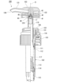
図1に示すように、第1実施形態に係る吐出器は、トリガー式噴出器1である。トリガー式噴出器1は、内容物を収容する容器体Aに装着される噴出器本体2と、内容物を噴出する噴出孔4(吐出孔)が形成され、噴出器本体2に装着されたノズル部材3と、噴出器本体2及びノズル部材3を覆うカバー部材5と、を備えている。容器体Aに収容される内容物としては、例えば、住居用や食器用の洗剤、空間や衣類などに用いる消臭・芳香剤、除菌用アルコールなど等が挙げられる。
なお、トリガー式噴出器1の各構成部品は、特に記載がなければ、合成樹脂を用いた成形品とされている。
以下の説明では、縦供給筒部10の中心軸線Oに沿った容器体A側を下側、その反対側を上側といい、中心軸線Oに沿う方向を上下方向という。また、この上下方向から見て、中心軸線Oに交差する方向を径方向といい、中心軸線O回りに周回する方向を周方向という。さらに、上下方向から見た平面視において、中心軸線Oに交差する一方向を前後方向といい、上下方向及び前後方向の双方向に直交する方向を左右方向という。
従って、容器体A内の内容物を、連通孔17を介して縦供給筒部10内に吸い上げ、シリンダ23内に導入することができる。これにより、次回の噴出に備えることができる。
次に、本発明の第2実施形態について説明する。以下の説明において、上述の実施形態と同一又は同等の構成については同一の符号を付し、その説明を簡略若しくは省略する。
従って、容器体内の内容物を、連通孔17を介してステム110内に吸い上げ、シリンダ112内に導入することができる。これにより、次回の噴出に備えることができる。
Claims (4)
- 容器体から内容物を吸い上げる縦供給筒部と、
前記縦供給筒部が吸い上げた前記内容物を吐出する吐出孔を有するノズル部材と、
ピストンの移動に伴って内部が加圧及び減圧し、且つ内部が前記縦供給筒部の内部に連通するシリンダと、
前記シリンダの内部の加圧及び減圧に応じて、前記縦供給筒部と前記吐出孔との連通及び遮断を切り替える切替弁と、を備え、
前記切替弁は、
前記縦供給筒部と前記吐出孔とを連通させる連通孔の開口周縁部に設けられた弁座と、 前記弁座に対して離反可能に着座するボール弁と、
前記ボール弁と前記連通孔の開口方向に対向する壁部と、
前記壁部から前記ボール弁に向かって突出する少なくとも3つの突起を含み、且つ前記弁座から離反した前記ボール弁によって、少なくとも前記連通孔の開口方向と交差する径方向に弾性変形する弾性突起群と、を備え、
前記弾性突起群は、前記壁部から前記ボール弁に向かうに従って、前記連通孔の中心軸線回りに沿う周方向の一方から他方に向けて延びる螺旋状に形成されている、ことを特徴とする吐出器。 - 前記弾性突起群は、前記ボール弁の前記壁部側の半分の領域に接触する、ことを特徴とする請求項1に記載の吐出器。
- 前記弾性突起群は、前記ボール弁に接触する少なくとも3つの接点を有し、
前記3つの接点を通る円の直径は、前記ボール弁の直径よりも小さい、ことを特徴とする請求項1または2に記載の吐出器。 - 前記弾性突起群は、前記連通孔の開口方向と交差する径方向内側を向く内面が、前記連通孔の中心軸線を中心とする円の接線方向に延びる平面状、若しくは前記連通孔の開口方向と交差する径方向外側に窪む曲面状に形成されている、ことを特徴とする請求項1~3のいずれか一項に記載の吐出器。
Priority Applications (1)
| Application Number | Priority Date | Filing Date | Title |
|---|---|---|---|
| JP2021214173A JP7696288B2 (ja) | 2021-12-28 | 2021-12-28 | 吐出器 |
Applications Claiming Priority (1)
| Application Number | Priority Date | Filing Date | Title |
|---|---|---|---|
| JP2021214173A JP7696288B2 (ja) | 2021-12-28 | 2021-12-28 | 吐出器 |
Publications (2)
| Publication Number | Publication Date |
|---|---|
| JP2023097836A JP2023097836A (ja) | 2023-07-10 |
| JP7696288B2 true JP7696288B2 (ja) | 2025-06-20 |
Family
ID=87071683
Family Applications (1)
| Application Number | Title | Priority Date | Filing Date |
|---|---|---|---|
| JP2021214173A Active JP7696288B2 (ja) | 2021-12-28 | 2021-12-28 | 吐出器 |
Country Status (1)
| Country | Link |
|---|---|
| JP (1) | JP7696288B2 (ja) |
Citations (3)
| Publication number | Priority date | Publication date | Assignee | Title |
|---|---|---|---|---|
| DE19803696A1 (de) | 1998-01-30 | 1999-08-05 | Alfred Von Schuckmann | Auf Flaschen o. dgl. zu befestigende Sprühpumpe |
| JP2018070232A (ja) | 2016-10-31 | 2018-05-10 | 株式会社吉野工業所 | トリガー式噴出器 |
| CN215612498U (zh) | 2021-08-06 | 2022-01-25 | 中山市永力塑料制品有限公司 | 一种喷雾装置 |
Family Cites Families (2)
| Publication number | Priority date | Publication date | Assignee | Title |
|---|---|---|---|---|
| IT1283712B1 (it) * | 1996-03-29 | 1998-04-30 | Coster Tecnologie Speciali Spa | Dispositivo spruzzatore azionabile manualmente tramite leve grilletto. |
| JP3628827B2 (ja) * | 1996-12-24 | 2005-03-16 | 株式会社吉野工業所 | トリガー式液体噴出ポンプ |
-
2021
- 2021-12-28 JP JP2021214173A patent/JP7696288B2/ja active Active
Patent Citations (3)
| Publication number | Priority date | Publication date | Assignee | Title |
|---|---|---|---|---|
| DE19803696A1 (de) | 1998-01-30 | 1999-08-05 | Alfred Von Schuckmann | Auf Flaschen o. dgl. zu befestigende Sprühpumpe |
| JP2018070232A (ja) | 2016-10-31 | 2018-05-10 | 株式会社吉野工業所 | トリガー式噴出器 |
| CN215612498U (zh) | 2021-08-06 | 2022-01-25 | 中山市永力塑料制品有限公司 | 一种喷雾装置 |
Also Published As
| Publication number | Publication date |
|---|---|
| JP2023097836A (ja) | 2023-07-10 |
Similar Documents
| Publication | Publication Date | Title |
|---|---|---|
| EP2696990B1 (en) | Improved trigger sprayer valves | |
| JP6258128B2 (ja) | トリガー式液体噴出器 | |
| US11596960B2 (en) | Sustained duration trigger sprayers and methods for making the same | |
| JP2004042045A (ja) | スプレーヘッド | |
| EP0867228B1 (en) | A pump mechanism for ejecting liquid | |
| US6318595B1 (en) | Finger-actuatable spray pump package with user-ready two-piece spray-through cap, pre-assembly cap, and method for making said package | |
| CN117440863A (zh) | 全塑料连续喷洒扳机喷洒器 | |
| JP7570790B2 (ja) | 吐出器 | |
| KR20030047725A (ko) | 분출펌프장치 및 트리거식 분출기 | |
| JP7696288B2 (ja) | 吐出器 | |
| US20090032554A1 (en) | Dispenser, a pump engine for a dispenser and a container for a dispenser | |
| US20210252529A1 (en) | Orifice and spray container including the same | |
| US5417356A (en) | Liquid dispensing assembly | |
| JP5110636B2 (ja) | トリガー式液体噴出器 | |
| JP7565852B2 (ja) | トリガー式液体噴出器 | |
| JP4628035B2 (ja) | ポンプスプレー装置 | |
| JP2025007063A (ja) | 吐出器 | |
| JP7676271B2 (ja) | トリガー式液体噴出器 | |
| JP2025154070A (ja) | トリガー式液体噴出器 | |
| JP2024171563A (ja) | トリガー式液体噴出器 | |
| JP2024122588A (ja) | トリガー式液体噴出器 | |
| US20140353404A1 (en) | Industrial trigger sprayer | |
| JP7493431B2 (ja) | 吐出器 | |
| JP7774941B2 (ja) | 吐出器 | |
| JP2024138623A (ja) | トリガー式液体噴出器 |
Legal Events
| Date | Code | Title | Description |
|---|---|---|---|
| A621 | Written request for application examination |
Free format text: JAPANESE INTERMEDIATE CODE: A621 Effective date: 20240701 |
|
| A977 | Report on retrieval |
Free format text: JAPANESE INTERMEDIATE CODE: A971007 Effective date: 20250129 |
|
| A131 | Notification of reasons for refusal |
Free format text: JAPANESE INTERMEDIATE CODE: A131 Effective date: 20250204 |
|
| A521 | Request for written amendment filed |
Free format text: JAPANESE INTERMEDIATE CODE: A523 Effective date: 20250328 |
|
| TRDD | Decision of grant or rejection written | ||
| A01 | Written decision to grant a patent or to grant a registration (utility model) |
Free format text: JAPANESE INTERMEDIATE CODE: A01 Effective date: 20250513 |
|
| A61 | First payment of annual fees (during grant procedure) |
Free format text: JAPANESE INTERMEDIATE CODE: A61 Effective date: 20250610 |
|
| R150 | Certificate of patent or registration of utility model |
Ref document number: 7696288 Country of ref document: JP Free format text: JAPANESE INTERMEDIATE CODE: R150 |