JP7686815B2 - Printing System - Google Patents

Printing System Download PDF

Info

Publication number
JP7686815B2
JP7686815B2 JP2024017618A JP2024017618A JP7686815B2 JP 7686815 B2 JP7686815 B2 JP 7686815B2 JP 2024017618 A JP2024017618 A JP 2024017618A JP 2024017618 A JP2024017618 A JP 2024017618A JP 7686815 B2 JP7686815 B2 JP 7686815B2
Authority
JP
Japan
Prior art keywords
unit
squeegee
transport
printing
control unit
Prior art date
Legal status (The legal status is an assumption and is not a legal conclusion. Google has not performed a legal analysis and makes no representation as to the accuracy of the status listed.)
Active
Application number
JP2024017618A
Other languages
Japanese (ja)
Other versions
JP2024040319A (en
Inventor
立雄 蛭川
毅 近藤
光昭 加藤
敦志 鳥居
淳 飯阪
Current Assignee (The listed assignees may be inaccurate. Google has not performed a legal analysis and makes no representation or warranty as to the accuracy of the list.)
Individual
Original Assignee
Individual
Priority date (The priority date is an assumption and is not a legal conclusion. Google has not performed a legal analysis and makes no representation as to the accuracy of the date listed.)
Filing date
Publication date
Application filed by Individual filed Critical Individual
Priority to JP2024017618A priority Critical patent/JP7686815B2/en
Publication of JP2024040319A publication Critical patent/JP2024040319A/en
Priority to JP2025084966A priority patent/JP7844715B2/en
Application granted granted Critical
Publication of JP7686815B2 publication Critical patent/JP7686815B2/en
Active legal-status Critical Current
Anticipated expiration legal-status Critical

Links

Images

Landscapes

  • Screen Printers (AREA)
  • Electric Connection Of Electric Components To Printed Circuits (AREA)
  • Inking, Control Or Cleaning Of Printing Machines (AREA)
  • Manufacturing Of Printed Wiring (AREA)

Description

本開示は、印刷装置及び収納装置に関する。 This disclosure relates to a printing device and a storage device.

従来、基板などの印刷対象に対してスクリーンマスクを用いて粘性流体の印刷処理を行う印刷装置において、スクリーンマスクの自動交換を行うものが知られている。例えば、特許文献1には、下方に突出したロッドと、ロッドを移動させることによりスクリーンマスクを摺動させて本体フレームへの出し入れを行う摺動子と、を備えた印刷装置が記載されている。 Conventionally, among printing devices that use a screen mask to perform a printing process of a viscous fluid on a printing target such as a substrate, there are known devices that automatically replace the screen mask. For example, Patent Document 1 describes a printing device that includes a rod that protrudes downward and a slider that slides the screen mask in and out of the main frame by moving the rod.

特開平04-107146号公報Japanese Patent Application Publication No. 04-107146

ところで、印刷装置には、スクリーンマスク以外にも例えばスキージなどの交換を要する部材が存在する。従来は、これらの部材の交換は作業者が手作業で行っていた。そのため、交換に作業者の手間がかかるという問題があった。 In addition to the screen mask, printing devices also have other components that require replacement, such as squeegees. Conventionally, these components have been replaced manually by workers. This has led to the problem that the replacement process requires a lot of time and effort on the part of the worker.

本開示は、上述した課題を解決するためになされたものであり、印刷装置の交換可能部材の自動交換を可能にすることを主目的とする。 This disclosure has been made to solve the above-mentioned problems, and its main purpose is to enable automatic replacement of replaceable parts of a printing device.

本開示は、上述した主目的を達成するために以下の手段を採った。 This disclosure takes the following steps to achieve the above-mentioned primary objective.

本開示の印刷装置は、
印刷対象に対してスクリーンマスクを用いて粘性流体の印刷処理を行う印刷装置であって、
前記粘性流体を収容するカートリッジと、スキージと、前記スクリーンマスクの清掃に用いられる清掃部材と、前記スクリーンマスクと、前記印刷対象を固定する支持部材と、のうち前記カートリッジと前記スキージと前記清掃部材との少なくともいずれか1種を含む2種以上の交換可能部材の各々について、該交換可能部材の交換位置への移動と該交換可能部材の搬出入との少なくとも一方を行う移動部と、
前記移動部を制御して前記交換可能部材を交換する交換処理を実行する交換制御部と、
を備えたものである。
The printing device of the present disclosure is
A printing apparatus that performs a printing process of a viscous fluid on a printing object using a screen mask,
a moving unit that moves the replaceable member to a replacement position and/or carries in and out the replaceable member for each of two or more replaceable members including at least one of the cartridge, the squeegee, and the cleaning member among the cartridge that contains the viscous fluid, the squeegee, the cleaning member used to clean the screen mask, the screen mask, and the support member that fixes the printing target;
an exchange control unit that controls the moving unit to execute an exchange process for exchanging the exchangeable member;
It is equipped with the following:

この印刷装置は、2種以上の交換可能部材の各々について交換可能部材の交換位置への移動と交換可能部材の搬出入との少なくとも一方を行う移動部を備えている。そして、この印刷装置は、この移動部を用いて、交換可能部材を交換する交換処理を行う。これにより、この印刷装置は、2種以上の交換可能部材の自動交換を行うことができる。ここで、「交換位置」は、引渡位置と受取位置とを含む。 This printing device is equipped with a movement unit that moves each of two or more types of exchangeable parts to an exchange position and/or transports the exchangeable parts in and out. The printing device then uses the movement unit to perform an exchange process to exchange the exchangeable parts. This allows the printing device to automatically exchange two or more types of exchangeable parts. Here, the "exchange position" includes a delivery position and a receiving position.

印刷システム1の構成の概略の一例を示す構成図。FIG. 1 is a diagram showing an example of a schematic configuration of a printing system. 印刷装置10及び収納装置100の概略縦断面図Schematic vertical cross-sectional view of the printing device 10 and the storage device 100. 印刷システム1の電気的な接続関係を示すブロック図。FIG. 2 is a block diagram showing the electrical connections of the printing system 1. スキージ固定部24,スキージ30,及びスキージ搬送治具110の斜視図。2 is a perspective view of a squeegee fixing portion 24, a squeegee 30, and a squeegee transport jig 110. FIG. 供給部40及びカートリッジ搬送治具120の平面図。FIG. 4 is a plan view of the supply unit 40 and the cartridge transport jig 120. 供給部40及びホルダ122の斜視図。FIG. 基板支持部材70及び支持部材搬送治具130の斜視図。3 is a perspective view of a substrate support member 70 and a support member transport jig 130. FIG. 突出状態の清掃部80及び清掃部材搬送治具140の斜視図。FIG. 4 is a perspective view of the cleaning unit 80 and the cleaning member transport jig 140 in a protruding state. 非突出状態の清掃部80の斜視図。FIG. 4 is a perspective view of the cleaning part 80 in a non-protruding state. 印刷処理と読取処理とを並行して行う様子を示す説明図。FIG. 4 is an explanatory diagram showing a state in which a printing process and a reading process are performed in parallel. 交換処理ルーチンの一例を示すフローチャート。10 is a flowchart showing an example of an exchange processing routine. カートリッジ49を供給ヘッド41に装着する動作の説明図。5A to 5C are explanatory diagrams illustrating an operation of mounting the cartridge 49 on the supply head 41. 清掃部材搬出処理の様子を示す説明図。FIG. 11 is an explanatory diagram showing a cleaning member carrying-out process. 清掃部材搬入処理の様子を示す説明図。FIG. 11 is an explanatory diagram showing a cleaning member carrying-in process. マスク搬出処理の様子を示す説明図。FIG. 11 is an explanatory diagram showing a mask unloading process. スキージ搬出処理の説明図。FIG. スキージ30をスキージ固定部24に装着する動作の説明図。5 is an explanatory diagram of an operation of attaching the squeegee 30 to the squeegee fixing portion 24. FIG. 基板支持部材搬出処理の説明図。FIG. 基板支持部材搬出処理の説明図。FIG.

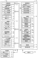
次に、本開示の実施の形態を図面を用いて説明する。図1は、本開示の一実施形態である印刷システム1の構成の概略の一例を示す構成図である。図2は、印刷装置10及び収納装置100の概略縦断面図である。図3は、印刷システム1の電気的な接続関係を示すブロック図である。図4は、スキージ固定部24,スキージ30,及びスキージ搬送治具110の斜視図である。図5は、供給部40及びカートリッジ搬送治具120の平面図である。図6は、供給部40及びホルダ122の斜視図である。図7は、基板支持部材70及び支持部材搬送治具130の斜視図である。図8は、突出状態の清掃部80及び清掃部材搬送治具140の斜視図である。図9は、非突出状態の清掃部80の斜視図である。印刷システム1は、粘性流体としてのはんだペースト(以下、単にはんだと称する)をスクリーンマスク55を用いて印刷対象(ここでは基板S)上に印刷処理する印刷装置10を備えている。また、印刷システム1は、印刷装置10で用いられる1種以上の交換可能部材13を収納する収納装置100と、印刷装置10での処理に関する情報を管理する管理コンピュータ(PC)150とを備えている。なお、印刷システム1は、電子部品を基板S上に実装する図示しない実装装置などの他の対基板作業装置をさらに備えた実装システムとして構成されていてもよい。粘性流体としては、はんだのほか、例えば導電性ペースト、接着剤などが挙げられる。印刷装置10は、印刷対象を異なる種類の基板Sに変更する段取り替えを行う際に、印刷処理に用いる交換可能部材13の自動交換が可能な装置として構成されている。交換可能部材13としては、はんだを収容するカートリッジ49と、スキージ30と、清掃部材82と、スクリーンマスク55と、基板支持部材70と、のうち1種以上が挙げられる。本実施形態の印刷装置10は、これら5種の全てが交換可能部材13として自動交換可能に構成されている。また、これら5種のうちスクリーンマスク55以外の交換処理は、図2に示すスキージ搬送治具110,カートリッジ搬送治具120,支持部材搬送治具130,清掃部材搬送治具140を用いて行われる。本実施形態において、左右方向(X軸)、前後方向(Y軸)及び上下方向(Z軸)は、図1,2に示した通りとする。 Next, an embodiment of the present disclosure will be described with reference to the drawings. FIG. 1 is a schematic diagram showing an example of the configuration of a printing system 1 according to an embodiment of the present disclosure. FIG. 2 is a schematic vertical cross-sectional view of a printing device 10 and a storage device 100. FIG. 3 is a block diagram showing the electrical connection relationship of the printing system 1. FIG. 4 is a perspective view of the squeegee fixing unit 24, the squeegee 30, and the squeegee transport jig 110. FIG. 5 is a plan view of the supply unit 40 and the cartridge transport jig 120. FIG. 6 is a perspective view of the supply unit 40 and the holder 122. FIG. 7 is a perspective view of the substrate support member 70 and the support member transport jig 130. FIG. 8 is a perspective view of the cleaning unit 80 and the cleaning member transport jig 140 in a protruding state. FIG. 9 is a perspective view of the cleaning unit 80 in a non-protruding state. The printing system 1 includes a printing device 10 that prints a solder paste (hereinafter simply referred to as solder) as a viscous fluid onto a printing target (here, a substrate S) using a screen mask 55. The printing system 1 also includes a storage device 100 that stores one or more types of replaceable members 13 used in the printing device 10, and a management computer (PC) 150 that manages information related to processing in the printing device 10. The printing system 1 may be configured as a mounting system further including other substrate-related work devices, such as a mounting device (not shown) that mounts electronic components on the substrate S. Examples of the viscous fluid include conductive paste and adhesives in addition to solder. The printing device 10 is configured as a device capable of automatically replacing the replaceable members 13 used in the printing process when changing the printing target to a different type of substrate S. The replaceable members 13 include one or more of the following: a cartridge 49 that stores solder, a squeegee 30, a cleaning member 82, a screen mask 55, and a substrate support member 70. In the printing device 10 of this embodiment, all of these five types are configured to be automatically replaceable as the replaceable members 13. Furthermore, the replacement process for these five types of masks other than the screen mask 55 is performed using a squeegee transport jig 110, a cartridge transport jig 120, a support member transport jig 130, and a cleaning member transport jig 140 shown in FIG. 2. In this embodiment, the left-right direction (X-axis), the front-back direction (Y-axis), and the up-down direction (Z-axis) are as shown in FIGS. 1 and 2.

印刷装置10は、図1,2に示すように、スキージ30を用いてスクリーンマスク55上のはんだをスクリーンマスク55に形成されたパターン孔58に押し込むことによりそのパターン孔58を介して下方の基板Sにはんだを塗布(印刷)する装置である。印刷装置10は、印刷制御部11(交換制御部の一例,図3)と、印刷処理部20と、供給部40と、マスク作業部50と、基板固定部60と、清掃部80と、読取部97と、を備えている。また、印刷装置10は、表示画面が表示され作業者による各種入力操作が可能な操作パネルとして構成された表示操作部98(図3)と、接続された他の機器と通信を行う図示しない通信部とを備えている。 As shown in Figs. 1 and 2, the printing device 10 is a device that applies (prints) solder onto the substrate S below through the pattern holes 58 by using a squeegee 30 to push solder on a screen mask 55 into the pattern holes 58 formed in the screen mask 55. The printing device 10 includes a print control unit 11 (an example of a replacement control unit, Fig. 3), a print processing unit 20, a supply unit 40, a mask work unit 50, a substrate fixing unit 60, a cleaning unit 80, and a reading unit 97. The printing device 10 also includes a display operation unit 98 (Fig. 3) configured as an operation panel on which a display screen is displayed and on which the operator can perform various input operations, and a communication unit (not shown) that communicates with other connected devices.

印刷制御部11は、CPUを中心とするマイクロプロセッサとして構成されており、処理プログラムを記憶するROM、作業領域として用いられるRAM、各種データを記憶するHDDなどを備えている。印刷制御部11は印刷装置10全体を制御する。 The print control unit 11 is configured as a microprocessor centered on a CPU, and includes a ROM for storing processing programs, a RAM used as a working area, and a HDD for storing various data. The print control unit 11 controls the entire printing device 10.

印刷処理部20は、印刷装置10の上段に配設されており、スクリーンマスク55を用いて粘性流体を基板S上に印刷処理するユニットである。印刷処理部20は、図3に示すように、印刷ヘッド21と、印刷移動部22と、スキージ昇降部23と、スキージ固定部24と、スキージ30と、搬送ロッド38とを備えている。印刷移動部22は、印刷ヘッド21を所定の印刷方向(ここでは前後方向)に移動するものであり、前後方向に形成されたガイドとガイドに沿って移動するスライダとスライダを駆動するモータとを備えている。スキージ昇降部23は、ピストンロッド23a(図2,図4)を有するエアシリンダとして構成され、ピストンロッド23aを昇降させることでスキージ固定部24及びスキージ30を昇降させる。印刷処理部20は、第1,第2スキージ30a,30bの2つのスキージ30を有しており、それに対応して2つのピストンロッド23aと2つのスキージ固定部24とを有している。 The print processing unit 20 is disposed on the upper stage of the printing device 10, and is a unit that prints a viscous fluid onto a substrate S using a screen mask 55. As shown in FIG. 3, the print processing unit 20 includes a print head 21, a print movement unit 22, a squeegee lifting unit 23, a squeegee fixing unit 24, a squeegee 30, and a transport rod 38. The print movement unit 22 moves the print head 21 in a predetermined printing direction (here, the front-rear direction), and includes a guide formed in the front-rear direction, a slider that moves along the guide, and a motor that drives the slider. The squeegee lifting unit 23 is configured as an air cylinder having a piston rod 23a (FIGS. 2 and 4), and raises and lowers the squeegee fixing unit 24 and the squeegee 30 by raising and lowering the piston rod 23a. The print processing section 20 has two squeegees 30, the first and second squeegees 30a and 30b, and correspondingly has two piston rods 23a and two squeegee fixing parts 24.

2つのスキージ固定部24は、前後対称に配設されている点以外は同様の構成であるため、以下、前側のスキージ固定部24について図4を用いて説明する。なお、図4は、スキージ固定部24にスキージ30が取り付けられる前の状態を示しており、この図4ではスキージ30は後述するスキージ交換処理で用いられるスキージ搬送治具110に取り付けられている。 The two squeegee fixing parts 24 have the same configuration except that they are arranged symmetrically from front to back, so below, the front squeegee fixing part 24 will be described using Figure 4. Note that Figure 4 shows the state before the squeegee 30 is attached to the squeegee fixing part 24, and in this Figure 4, the squeegee 30 is attached to a squeegee transport jig 110 that is used in the squeegee replacement process described below.

スキージ固定部24は、スキージ30(ここでは第1スキージ30a)を固定する固定状態とスキージ30を固定しない解除状態とを切り替えるように構成された機構である。図4に示すように、スキージ固定部24は、ピストンロッド23aの下端に接続されており、エアシリンダ25と、規制部材26と、を備えている。エアシリンダ25は、下方に突出するシリンダ軸25aを昇降させる機構である。シリンダ軸25aの下端にはフランジ25bが形成されており、フランジ25bの上面がスキージ30を下方から支持するように構成されている。規制部材26は、固定状態でスキージ30の突出部34と係合してスキージ30前後の移動を規制する部材である。規制部材26は、エアシリンダ25の左右両側にそれぞれ1つずつ配設されている。各々の規制部材26は、前方に突出する爪部27a,27bを有している。爪部27a,27bの下面には上方に向かって凹んだ凹部28a,28bがそれぞれ形成されている。スキージ固定部24では、エアシリンダ25がフランジ25bを上昇させた状態が固定状態であり、固定状態に比してエアシリンダ25がフランジ25bを下降させた状態が解除状態である。このフランジ25bの昇降により、スキージ固定部24は、固定状態ではフランジ25bの上面と規制部材26の下面との間でスキージ30の取付部材32を挟持する。また、スキージ固定部24は、解除状態では固定状態に比してフランジ25bと規制部材26とが相対的に上下に離間することで、スキージ30の固定を解除する。 The squeegee fixing part 24 is a mechanism configured to switch between a fixed state in which the squeegee 30 (here, the first squeegee 30a) is fixed and a released state in which the squeegee 30 is not fixed. As shown in FIG. 4, the squeegee fixing part 24 is connected to the lower end of the piston rod 23a and includes an air cylinder 25 and a regulating member 26. The air cylinder 25 is a mechanism for raising and lowering the cylinder shaft 25a that protrudes downward. A flange 25b is formed at the lower end of the cylinder shaft 25a, and the upper surface of the flange 25b is configured to support the squeegee 30 from below. The regulating member 26 is a member that engages with the protruding part 34 of the squeegee 30 in the fixed state to regulate the movement of the squeegee 30 forward and backward. One regulating member 26 is disposed on each of the left and right sides of the air cylinder 25. Each regulating member 26 has claws 27a and 27b that protrude forward. The lower surfaces of the claws 27a and 27b are respectively formed with upwardly recessed recesses 28a and 28b. In the squeegee fixing part 24, the state in which the air cylinder 25 raises the flange 25b is the fixed state, and the state in which the air cylinder 25 lowers the flange 25b compared to the fixed state is the released state. Due to this raising and lowering of the flange 25b, in the fixed state, the squeegee fixing part 24 clamps the mounting member 32 of the squeegee 30 between the upper surface of the flange 25b and the lower surface of the regulating member 26. In the released state, the squeegee fixing part 24 releases the fixation of the squeegee 30 by relatively separating the flange 25b and the regulating member 26 vertically compared to the fixed state.

図4に示すように、スキージ30は、パターン孔58(図2)よりも左右に長い長さに形成されたスキージブレード31と、スキージブレード31をスキージ固定部24に取り付けるための取付部材32と、を備えている。取付部材32は、位置決め部材33と、突出部34と、軸部材35と、フランジ部36とを備えている。位置決め部材33は、上面視でU字状に形成された部材であり、スキージ固定部24のシリンダ軸25aが前後に通過可能な開口部33aと、位置決め部材33の下面であり開口部33aに向かって(U字の内側に向かって)水平に突出する被把持面33bとを有している。スキージ固定部24のシリンダ軸25aが後方から前方に向かって位置決め部材33の開口部33a内に入っていくと、フランジ25bの上面が被把持面33bと上下に対向する。この被把持面33bと取付部材32の上面である被把持面32aとが、スキージ固定部24のシリンダ軸25aの上面と規制部材26の下面とに挟持されることで、スキージ30はスキージ固定部24に把持固定される。突出部34は、位置決め部材33の左右両側に1つずつ配設されており、いずれの突出部34もスキージ固定部24の凹部28a,28b内に嵌まり込んで規制部材26と係合するように構成されている。規制部材26と突出部34とが係合することで、スキージ固定部24に対するスキージ30の前後方向への移動が規制される。軸部材35は、位置決め部材33の左右両側に1つずつ配設されており、各々が突出部34の上面から上方に突出している。軸部材35の上端には、それぞれフランジ部36が形成されている。フランジ部36は、スキージ搬送治具110の係合部115と係合する部材である。 As shown in FIG. 4, the squeegee 30 includes a squeegee blade 31 formed to be longer in the left-right direction than the pattern hole 58 (FIG. 2), and an attachment member 32 for attaching the squeegee blade 31 to the squeegee fixing portion 24. The attachment member 32 includes a positioning member 33, a protruding portion 34, an axis member 35, and a flange portion 36. The positioning member 33 is a member formed in a U-shape when viewed from above, and has an opening 33a through which the cylinder shaft 25a of the squeegee fixing portion 24 can pass back and forth, and a gripped surface 33b which is the lower surface of the positioning member 33 and protrudes horizontally toward the opening 33a (toward the inside of the U). When the cylinder shaft 25a of the squeegee fixing portion 24 enters the opening 33a of the positioning member 33 from the rear to the front, the upper surface of the flange 25b faces the gripped surface 33b in the vertical direction. The gripped surface 33b and the gripped surface 32a, which is the upper surface of the mounting member 32, are sandwiched between the upper surface of the cylinder shaft 25a of the squeegee fixing portion 24 and the lower surface of the regulating member 26, so that the squeegee 30 is gripped and fixed to the squeegee fixing portion 24. The protrusions 34 are arranged on both the left and right sides of the positioning member 33, and each of the protrusions 34 is configured to fit into the recesses 28a, 28b of the squeegee fixing portion 24 and engage with the regulating member 26. The engagement of the regulating member 26 with the protrusions 34 regulates the movement of the squeegee 30 in the front-rear direction relative to the squeegee fixing portion 24. The shaft members 35 are arranged on both the left and right sides of the positioning member 33, and each protrudes upward from the upper surface of the protrusions 34. A flange portion 36 is formed on the upper end of each of the shaft members 35. The flange portion 36 is a member that engages with the engagement portion 115 of the squeegee transport jig 110.

図4には、印刷装置10がスキージ30の自動交換に用いるスキージ搬送治具110も併せて図示している。スキージ搬送治具110は、枠状のフレーム111と、スキージ30を取付可能なホルダ112と、フレーム111の右側面の後端付近に配置されたバーコード116とを備えている。スキージ搬送治具110は、前後対称な2つのホルダ112を備えている。各々のホルダ112は、フレーム111を左右に掛け渡すように配置された本体部分と、本体部分からフレーム111の前後方向内側に突出する支持部113とを備えている。支持部113は、各々のホルダ112について左右に並んで2つずつ配設されている。支持部113は、図4右上の拡大図に示すように、スキージ30の軸部材35が前後方向に通過可能な開口部114を有している。また、支持部113は、スキージ30のフランジ部36が係合してスキージ30を固定する係合部115を有している。係合部115は、支持部113の開口縁に形成された、フランジ部36の下面側の部分がはまる凹部である。スキージ30は、係合部115にフランジ部36がはまると、自重によりスキージ搬送治具110に対するXY方向への相対移動が規制される。また、スキージ30は、上方に移動されてフランジ部36が係合部115から外れた位置(取外位置とも称する)では、XY方向への移動規制が解除され、開口部114から取外可能になる。バーコード116は、スキージ搬送治具110に取り付けられているスキージ30を識別するための識別情報であり、例えば作業者によって予め取り付けられる。 4 also illustrates a squeegee transport jig 110 used by the printing device 10 for automatic replacement of the squeegee 30. The squeegee transport jig 110 includes a frame 111, a holder 112 to which the squeegee 30 can be attached, and a barcode 116 located near the rear end of the right side of the frame 111. The squeegee transport jig 110 includes two holders 112 that are symmetrical from front to back. Each holder 112 includes a main body portion that is arranged to span the frame 111 from left to right, and a support portion 113 that protrudes from the main body portion to the inside of the frame 111 in the front-rear direction. Two support portions 113 are arranged side by side on the left and right for each holder 112. As shown in the enlarged view in the upper right of FIG. 4, the support portion 113 has an opening 114 through which the shaft member 35 of the squeegee 30 can pass in the front-rear direction. The support 113 also has an engagement portion 115 that engages with the flange 36 of the squeegee 30 to fix the squeegee 30. The engagement portion 115 is a recess formed on the opening edge of the support 113 into which the lower side of the flange 36 fits. When the flange 36 fits into the engagement portion 115, the squeegee 30 is restricted from moving in the XY directions relative to the squeegee transport jig 110 by its own weight. When the squeegee 30 is moved upward and the flange 36 is disengaged from the engagement portion 115 (also referred to as the removal position), the restriction on movement in the XY directions is released and the squeegee 30 can be removed from the opening 114. The barcode 116 is identification information for identifying the squeegee 30 attached to the squeegee transport jig 110, and is attached in advance by an operator, for example.

搬送ロッド38は、図示しないモーターにより昇降可能に印刷ヘッド21に配設されている(図2)。この搬送ロッド38は、スキージ30よりも下方に突出した状態で印刷移動部22により前後に移動することで、搬送レール53上に載置されたスクリーンマスク55及び各搬送治具を前後に押して搬送する。これにより、搬送ロッド38は、収納装置100から印刷装置10へのスクリーンマスク55及び各搬送治具の搬出入が可能である。 The transport rod 38 is disposed on the print head 21 so that it can be raised and lowered by a motor (not shown) (Figure 2). This transport rod 38 is moved back and forth by the print moving unit 22 while protruding below the squeegee 30, thereby pushing and transporting the screen mask 55 and each transport tool placed on the transport rail 53 back and forth. This allows the transport rod 38 to transport the screen mask 55 and each transport tool from the storage device 100 to the printing device 10.

供給部40は、カートリッジ49に収容されたはんだをスクリーンマスク55上へ供給する装置である。供給部40は、供給ヘッド41と、供給移動部46とを備えている。供給ヘッド41は、カートリッジ49を位置決めして保持し、はんだを吐出させるものである。供給移動部46は、供給ヘッド41をX軸方向(左右方向)に移動するものである。供給ヘッド41は、図3などに示すように、エア供給部42と、クランプ部43と、回動モータ44と、を備えている。また、供給ヘッド41は、図6に示すように、供給移動部46に配設される背板部41aと、背板部41aの上端から前方に突出して形成された固定部材41bとを備えている。供給ヘッド41は、スクリーンマスク55上のはんだの吐出位置と、交換用のカートリッジ49が配置されたカートリッジ搬送治具120のホルダ122との間で移動する。エア供給部42は、カートリッジ49に接続し、はんだをカートリッジ49から吐出するためのエアをカートリッジ49へ供給するものである。エア供給部42は、円筒状であり、カートリッジ49に形成された孔状の接続部49dに挿入される。このエア供給部42は、接続部49dに挿入されることによりカートリッジ49の位置が固定されるため、カートリッジ49の位置決め部を兼ねている。このエア供給部42は、下方に開口を有し、固定部材41bの下面に配設されている。このエア供給部42は、図示しない配管を介して供給されたエアを開口から排出する。 The supply unit 40 is a device that supplies the solder contained in the cartridge 49 onto the screen mask 55. The supply unit 40 includes a supply head 41 and a supply moving unit 46. The supply head 41 positions and holds the cartridge 49, and discharges the solder. The supply moving unit 46 moves the supply head 41 in the X-axis direction (left and right direction). As shown in FIG. 3, the supply head 41 includes an air supply unit 42, a clamp unit 43, and a rotary motor 44. As shown in FIG. 6, the supply head 41 includes a back plate portion 41a disposed on the supply moving unit 46, and a fixing member 41b formed by protruding forward from the upper end of the back plate portion 41a. The supply head 41 moves between the solder discharge position on the screen mask 55 and the holder 122 of the cartridge transport jig 120 in which the replacement cartridge 49 is disposed. The air supply unit 42 is connected to the cartridge 49 and supplies air to the cartridge 49 for discharging solder from the cartridge 49. The air supply unit 42 is cylindrical and is inserted into a hole-shaped connection portion 49d formed in the cartridge 49. The air supply unit 42 also serves as a positioning portion for the cartridge 49, as the position of the cartridge 49 is fixed by being inserted into the connection portion 49d. The air supply unit 42 has an opening on the lower side and is disposed on the lower surface of the fixing member 41b. The air supply unit 42 exhausts air supplied via a pipe (not shown) from the opening.

クランプ部43は、カートリッジ49を固定する部材である。このクランプ部43は、背板部41aの下側に回動可能に軸支されており、回動モータ44からの駆動力により、カートリッジ49を固定する固定位置とカートリッジ49の固定を解除する解除位置との間で移動(ここでは回動)する。解除位置は、クランプ部43が背板部41aの形成方向と同じ垂直状態となる位置である。固定位置は、クランプ部43が背板部41aの形成方向に直交する水平状態となる位置である。エア供給部42がカートリッジ49の接続部49dに接続した状態において、クランプ部43が固定位置に移動すると、クランプ部43がカートリッジ49を下方から支持して固定する。クランプ部43は、中空の円板形状に形成されており、中空部分にカートリッジ49の底部がはまるようになっている。 The clamp section 43 is a member that fixes the cartridge 49. The clamp section 43 is rotatably supported on the lower side of the back plate section 41a, and moves (here, rotates) between a fixed position where the cartridge 49 is fixed and a release position where the fixation of the cartridge 49 is released by the driving force from the rotation motor 44. The release position is a position where the clamp section 43 is in a vertical state that is the same as the formation direction of the back plate section 41a. The fixed position is a position where the clamp section 43 is in a horizontal state perpendicular to the formation direction of the back plate section 41a. When the air supply section 42 is connected to the connection section 49d of the cartridge 49 and the clamp section 43 moves to the fixed position, the clamp section 43 supports and fixes the cartridge 49 from below. The clamp section 43 is formed in a hollow disk shape, and the bottom of the cartridge 49 fits into the hollow part.

供給移動部46は、印刷ヘッド23の前面に配設されている。このため、供給ヘッド41は、印刷移動部24によりY軸方向へ移動し、供給移動部46によりX軸方向に移動する。供給移動部46は、ガイド46aと、ボールねじ46bと、駆動モータ48とを備えている。駆動モータ48がボールねじ46bを回転させることで、供給ヘッド41はガイド46aに沿って左右方向に移動する。 The supply movement unit 46 is disposed in front of the print head 23. Therefore, the supply head 41 is moved in the Y-axis direction by the print movement unit 24, and moved in the X-axis direction by the supply movement unit 46. The supply movement unit 46 includes a guide 46a, a ball screw 46b, and a drive motor 48. When the drive motor 48 rotates the ball screw 46b, the supply head 41 moves left and right along the guide 46a.

カートリッジ49は、円筒状の本体部49aと、この本体部49aより大きな径で形成され本体部49aの上側及び下側に配設されたフランジ部49bと、上側のフランジ部49bの中央に形成された接続部49dとを有している。また、カートリッジ49の下側のフランジ部49bの中央には、はんだを外部に吐出する図示しないノズルが形成されている。接続部49dは、エア供給部42が挿入接続される孔である。カートリッジ49は、エア供給部42から接続部49dにエアが供給されると、本体部49a内部の図示しない押圧部材が押圧されて、内部のはんだをノズルから吐出する。 The cartridge 49 has a cylindrical main body 49a, flanges 49b formed with a larger diameter than the main body 49a and disposed on the upper and lower sides of the main body 49a, and a connection 49d formed in the center of the upper flange 49b. A nozzle (not shown) that ejects solder to the outside is formed in the center of the lower flange 49b of the cartridge 49. The connection 49d is a hole into which the air supply unit 42 is inserted and connected. When air is supplied from the air supply unit 42 to the connection 49d of the cartridge 49, a pressing member (not shown) inside the main body 49a is pressed, ejecting the solder from the nozzle.

図5には、印刷装置10がカートリッジ49の自動交換に用いるカートリッジ搬送治具120も併せて図示している。カートリッジ搬送治具120は、枠状のフレーム121と、カートリッジ49を取付可能な複数のホルダ122と、バーコード126と、を備えている。ホルダ122は、X方向に複数(図5では5個)配列され、各々がフレーム121の後方に取り付けられている。ホルダ122は、図6に示すように、カートリッジ49の本体部49aが通過可能な開口部124を有する支持部123と、支持部123に形成されカートリッジ49の上側のフランジ部49bが係合してカートリッジ49を固定する係合部125とを有している。支持部123は、C字状の板状部材である。係合部125は、支持部123の開口縁に形成された、上側のフランジ部49bの下面側の部分がはまる凹部である。カートリッジ49は、係合部125にフランジ部49bがはまると、自重により、カートリッジ搬送治具120に対するXY方向への相対移動が規制される。また、カートリッジ49は、上方に移動されてフランジ部49bが係合部125から外れた位置(取外位置とも称する)では、XY方向への移動規制が解除され、開口部124から取外可能になる。なお、上述した供給ヘッド41のクランプ部43が固定位置に回動移動すると、クランプ部43がホルダ122に取り付けられたカートリッジ49を押し上げ、ホルダ122の取外位置にカートリッジ49を位置させる。即ち、クランプ部43によるカートリッジ49の固定動作が、ホルダ122からのカートリッジ49の移動規制の解除動作を兼ねる。バーコード126は、カートリッジ搬送治具120の右側面の後端付近に配設されており、より具体的には最も右に位置するホルダ122の右側面に配設されている。バーコード126は、カートリッジ搬送治具120に取り付けられているカートリッジ49を識別するための識別情報であり、例えば作業者によって予め取り付けられる。 5 also illustrates a cartridge transport jig 120 used by the printing device 10 for automatic replacement of the cartridge 49. The cartridge transport jig 120 includes a frame 121, a plurality of holders 122 to which the cartridge 49 can be attached, and a barcode 126. A plurality of holders 122 (five in FIG. 5) are arranged in the X direction, and each is attached to the rear of the frame 121. As shown in FIG. 6, the holder 122 includes a support portion 123 having an opening 124 through which the main body portion 49a of the cartridge 49 can pass, and an engagement portion 125 formed on the support portion 123 and engaged with the upper flange portion 49b of the cartridge 49 to fix the cartridge 49. The support portion 123 is a C-shaped plate member. The engagement portion 125 is a recess formed on the edge of the opening of the support portion 123 into which the lower surface portion of the upper flange portion 49b fits. When the flange portion 49b fits into the engaging portion 125, the cartridge 49 is restricted in its movement in the XY directions relative to the cartridge transport jig 120 by its own weight. When the cartridge 49 is moved upward and the flange portion 49b is disengaged from the engaging portion 125 (also referred to as a removal position), the restriction on the movement in the XY directions is released and the cartridge 49 can be removed from the opening 124. When the clamp portion 43 of the supply head 41 described above is rotated to the fixed position, the clamp portion 43 pushes up the cartridge 49 attached to the holder 122 and positions the cartridge 49 at the removal position of the holder 122. That is, the fixing operation of the cartridge 49 by the clamp portion 43 also serves as the release operation of the restriction on the movement of the cartridge 49 from the holder 122. The barcode 126 is disposed near the rear end of the right side surface of the cartridge transport jig 120, more specifically, on the right side surface of the rightmost holder 122. The barcode 126 is identification information for identifying the cartridge 49 attached to the cartridge transport jig 120, and is attached in advance, for example, by an operator.

マスク作業部50は、図2に示すように上下方向で印刷処理部20と基板固定部60との間に配設されており、スクリーンマスク55を固定保持するユニットである。マスク作業部50は、図3などに示すように、マスク固定部51と、位置調整部52と、搬送レール53と、を備えている。マスク固定部51は、スクリーンマスク55を位置決めして水平な姿勢で支持固定するものである。位置調整部52は、基板固定部60に固定された基板Sに対して適正な位置にスクリーンマスク55のパターン孔58が配置されるようマスク固定部51をXY方向に位置調整するものである。搬送レール53は、前後方向に伸びた左右1対のレールであり、搬送ロッド38に押されたスクリーンマスク55や各搬送治具が前後方向に沿って移動するようにこれらをガイドする。スクリーンマスク55は、所望の配線パターンなどのパターン孔58が形成されたマスク本体56と、マスク本体56を所定のテンションで保持する枠体57とを備えている。マスク本体56は、例えば金属の薄板である。スクリーンマスク55の下面には位置認識用の識別部(例えばマーク)が形成されている。スクリーンマスク55の右側面の後端付近には、スクリーンマスク55の識別情報を表すバーコード57a(図5)が配設されている。このバーコードは例えば作業者によって予め取り付けられる。 As shown in FIG. 2, the mask working section 50 is disposed between the print processing section 20 and the substrate fixing section 60 in the vertical direction, and is a unit that fixes and holds the screen mask 55. As shown in FIG. 3 and other figures, the mask working section 50 includes a mask fixing section 51, a position adjustment section 52, and a conveying rail 53. The mask fixing section 51 positions the screen mask 55 and supports and fixes it in a horizontal position. The position adjustment section 52 adjusts the position of the mask fixing section 51 in the XY direction so that the pattern holes 58 of the screen mask 55 are positioned at an appropriate position relative to the substrate S fixed to the substrate fixing section 60. The conveying rails 53 are a pair of left and right rails that extend in the front-rear direction, and guide the screen mask 55 and each conveying tool pressed by the conveying rod 38 so that they move along the front-rear direction. The screen mask 55 includes a mask body 56 in which pattern holes 58 such as a desired wiring pattern are formed, and a frame body 57 that holds the mask body 56 with a predetermined tension. The mask body 56 is, for example, a thin metal plate. An identification portion (for example, a mark) for position recognition is formed on the underside of the screen mask 55. A barcode 57a (FIG. 5) indicating identification information of the screen mask 55 is disposed near the rear end of the right side surface of the screen mask 55. This barcode is attached in advance, for example, by an operator.

基板固定部60は、マスク作業部50の下方に配設され、基板Sを搬入し、搬入した基板Sを位置決めして支持し、スクリーンマスク55に接触,離間させるユニットである。基板固定部60は、図1~3に示すように、基板搬送コンベア61と、基板ガイド62と、基板ガイド移動部63(図3参照)と、支持台昇降部65と、固定部昇降部66と、支持台67と、基板支持部材70と、を備えている。基板搬送コンベア61は、1対のサイドフレーム60bの各々に設けられ、基板SをX方向に搬送する。基板ガイド62は、1対のサイドフレーム60bの各々の上面に設けられた板状部材である。基板ガイド移動部63は、1対のサイドフレーム60bを前後方向に移動させて互いに接近・離間させる機構である。これにより、基板ガイド62も前後方向に移動し、基板Sの上面と基板ガイド62の上面とが面一の状態で基板Sを挟み固定する。支持台昇降部65は、基板固定部60の本体60aに対して支持台67を昇降する機構である。固定部昇降部66は、印刷装置10本体に対して基板固定部60の全体を昇降する機構である。支持台67は、基板支持部材70を配置可能な部材である。なお、基板固定部60は、基板支持部材70の支持台67上での固定及び位置決めを行う図示しない固定部や位置調整部を備えている。 The substrate fixing unit 60 is disposed below the mask working unit 50 and is a unit that carries in the substrate S, positions and supports the carried-in substrate S, and brings it into contact with and away from the screen mask 55. As shown in FIGS. 1 to 3, the substrate fixing unit 60 includes a substrate transport conveyor 61, a substrate guide 62, a substrate guide moving unit 63 (see FIG. 3), a support platform lifting unit 65, a fixing unit lifting unit 66, a support platform 67, and a substrate support member 70. The substrate transport conveyor 61 is provided on each of the pair of side frames 60b and transports the substrate S in the X direction. The substrate guide 62 is a plate-shaped member provided on the upper surface of each of the pair of side frames 60b. The substrate guide moving unit 63 is a mechanism that moves the pair of side frames 60b in the front-rear direction to move them closer to and away from each other. As a result, the board guide 62 also moves in the front-rear direction, clamping and fixing the board S in a state where the top surface of the board S and the top surface of the board guide 62 are flush with each other. The support platform lifting unit 65 is a mechanism that raises and lowers the support platform 67 relative to the main body 60a of the board fixing unit 60. The fixing unit lifting unit 66 is a mechanism that raises and lowers the entire board fixing unit 60 relative to the main body of the printing device 10. The support platform 67 is a member on which the board support member 70 can be positioned. The board fixing unit 60 is equipped with fixing units and position adjustment units (not shown) that fix and position the board support member 70 on the support platform 67.

基板支持部材70は、支持台67上に配置され、図示しない減圧装置に配管で接続されて、負圧により基板Sを下面側から支持しつつ吸着固定する部材である。基板支持部材70は、図7に示すように、本体部70aと、本体部70aの左右から突出するように配設された円柱状の一対の突起部71,71と、突起部71よりも前方に配設された一対の突起部72,72と、本体部70aの上面に開口する複数の吸引口73と、を備えている。この複数の突起部71,72は、図7に示す支持部材搬送治具130の第1~第4突起保持部132~135と係合する係合部として機能する。また、本体部70aの上面には、位置認識用の識別部75(例えばマーク)と、基板支持部材70の種別認識用のバーコード76とが形成されている。基板支持部材70は、基板Sに応じて交換される。 The substrate support member 70 is placed on the support stand 67 and is connected to a pressure reducing device (not shown) by piping, and is a member that supports and fixes the substrate S from the underside by negative pressure. As shown in FIG. 7, the substrate support member 70 has a main body 70a, a pair of cylindrical protrusions 71, 71 arranged to protrude from the left and right sides of the main body 70a, a pair of protrusions 72, 72 arranged forward of the protrusions 71, and a plurality of suction ports 73 opening on the upper surface of the main body 70a. The plurality of protrusions 71, 72 function as engagement parts that engage with the first to fourth protrusion holders 132 to 135 of the support member transport jig 130 shown in FIG. 7. In addition, an identification part 75 (e.g., a mark) for position recognition and a bar code 76 for type recognition of the substrate support member 70 are formed on the upper surface of the main body 70a. The substrate support member 70 is replaced depending on the substrate S.

図7には、印刷装置10が基板支持部材70の自動交換に用いる支持部材搬送治具130も併せて図示している。支持部材搬送治具130は、枠状のフレーム131と、フレーム131の内側に配設された第1~第4突起保持部132~135と、フレーム131の右側面の後端付近に配置されたバーコード136とを備えている。第1~第4突起保持部132~135は、前方から後方に向かってこの順で配設されている。第1~第4突起保持部132~135は、それぞれ左右方向に1対ずつ配設されており、フレーム131の下方に伸びる腕部の先端に配設されている。支持部材搬送治具130は、第1,第2突起保持部132,133により基板支持部材70を1つ取り付け可能であり、第3,第4突起保持部134,135により基板支持部材70を1つ取り付け可能である。第1~第4突起保持部132~135の上面には基板支持部材70の突起部71や突起部72の外径よりもわずかに大きい凹部が形成されている。この凹部に突起部71,72が載置されることで、支持部材搬送治具130は基板支持部材70の前後方向の相対位置を固定しつつ基板支持部材70を搬送可能である。バーコード136は、支持部材搬送治具130に取り付けられている基板支持部材70を識別するための識別情報であり、例えば作業者によって予め取り付けられる。 Figure 7 also illustrates the support member transport jig 130 used by the printing device 10 for automatic replacement of the substrate support member 70. The support member transport jig 130 includes a frame 131, first to fourth protrusion holders 132 to 135 arranged inside the frame 131, and a bar code 136 arranged near the rear end of the right side of the frame 131. The first to fourth protrusion holders 132 to 135 are arranged in this order from the front to the rear. The first to fourth protrusion holders 132 to 135 are each arranged in pairs in the left and right directions, and are arranged at the tips of arms extending downward from the frame 131. The support member transport jig 130 can attach one substrate support member 70 by the first and second protrusion holders 132 and 133, and can attach one substrate support member 70 by the third and fourth protrusion holders 134 and 135. The upper surfaces of the first to fourth protrusion holders 132 to 135 have recesses formed thereon that are slightly larger than the outer diameter of the protrusions 71 and 72 of the substrate support member 70. By placing the protrusions 71 and 72 in these recesses, the support member transport jig 130 can transport the substrate support member 70 while fixing the relative position of the substrate support member 70 in the front-to-rear direction. The barcode 136 is identification information for identifying the substrate support member 70 attached to the support member transport jig 130, and is attached in advance by an operator, for example.

清掃部80は、図2に示すように上下方向でマスク作業部50と基板固定部60との間に配設されており、スクリーンマスク55の裏面を清掃する清掃処理を行うユニットである。図8,9に示すように、清掃部80は、清掃部材82を含み収納装置100との間で交換が可能な交換モジュール81と、交換モジュール81を載置する載置部材84と、交換モジュール81及び載置部材84を支持する支持部材86と、交換モジュール81及び載置部材84を移動させる清掃移動部87とを備えている。なお、図8には、印刷装置10が交換モジュール81の自動交換に用いる清掃部材搬送治具140も併せて図示している。また、清掃移動部87は、交換モジュール81及び載置部材84を前方に突出させる突出状態と突出させない非突出状態とを切り替えることができる。図8は突出状態を示し、図9は非突出状態を示している。 The cleaning unit 80 is disposed between the mask working unit 50 and the substrate fixing unit 60 in the vertical direction as shown in FIG. 2, and is a unit that performs a cleaning process to clean the back surface of the screen mask 55. As shown in FIGS. 8 and 9, the cleaning unit 80 includes a replacement module 81 that includes a cleaning member 82 and can be replaced between the storage device 100, a mounting member 84 on which the replacement module 81 is placed, a support member 86 that supports the replacement module 81 and the mounting member 84, and a cleaning movement unit 87 that moves the replacement module 81 and the mounting member 84. Note that FIG. 8 also illustrates a cleaning member transport jig 140 that the printing device 10 uses for automatic replacement of the replacement module 81. The cleaning movement unit 87 can switch between a protruding state in which the replacement module 81 and the mounting member 84 protrude forward and a non-protruding state in which they do not protrude. FIG. 8 shows the protruding state, and FIG. 9 shows the non-protruding state.

交換モジュール81は、第1ローラ81aと、第2ローラ81bと、清掃部材82と、取付部材83とを備えている。清掃部材82は、スクリーンマスク55を清掃するための部材であり、本実施形態ではスクリーンマスク55を拭取により清掃する拭取シートとした。第1ローラ81aには清掃部材82が巻き付けられている。第2ローラ81bは、第1ローラ81aよりも前方に配置され、第1ローラ81aから繰り出された清掃部材82を繰り込む。清掃部材82のうち第1ローラ81aに繰り出されて第2ローラ81bに巻き取られるまでの部分が、スクリーンマスク55の清掃に用いられる。 The replacement module 81 includes a first roller 81a, a second roller 81b, a cleaning member 82, and an attachment member 83. The cleaning member 82 is a member for cleaning the screen mask 55, and in this embodiment is a wiping sheet that cleans the screen mask 55 by wiping it. The cleaning member 82 is wound around the first roller 81a. The second roller 81b is disposed forward of the first roller 81a, and retracts the cleaning member 82 reeled out from the first roller 81a. The portion of the cleaning member 82 that is reeled out by the first roller 81a and reeled in by the second roller 81b is used to clean the screen mask 55.

取付部材83は、第1,第2ローラ81a,81b及び清掃部材82を取り付けるための部材である。取付部材83は、上下が開口した箱状の部材である箱体83aを有している。箱体83aの内側には左右に対向する2対計4個(3個のみ図示)の軸受83bが配設されている。2対の軸受83bの各々には、第1,第2ローラ81a,81bの軸端をそれぞれ挿入可能であり、これにより軸受83bは第1,第2ローラ81a,81bを回転可能に軸支する。図示しない右前方の軸受83bは、箱体83aの外側に配設されたギヤ83cと同軸に接続されており、これにより第2ローラ81bとギヤ83cとは一体的に回転する。ギヤ83cは、非突出状態では巻取モータ86aのギヤ86bと噛合するように配置されており、これにより巻取モータ86aからの駆動力で第2ローラ81bが回転して清掃部材82を巻き取るようになっている。また、箱体83aには、取付部材83から左右方向両側にそれぞれ突出する突出部83dを有している。本実施形態では、箱体83aの右側には突出部83dが1個配設され、箱体83aの左側には突出部83dが2個配設されている。この複数の突出部83dは、図8に示す清掃部材搬送治具140の突起保持部142と係合する係合部として機能する。箱体83aの前面には、左右両端の各々に受け部材83eが配設されている。受け部材83eは、左右外側に向かって開口する凹部を有しており、非突出状態ではロック機構86cのロック部材86dと係合するように構成されている。箱体83aの左右の側面にはそれぞれ開口部83fが形成されており、開口部83f内にはY方向に延びる係合軸83gが配置されている。係合軸83gは、載置部材84の爪部材84cと係合するように構成されている(図8右上の拡大図)。 The mounting member 83 is a member for mounting the first and second rollers 81a, 81b and the cleaning member 82. The mounting member 83 has a box body 83a, which is a box-shaped member with an opening at the top and bottom. Inside the box body 83a, two pairs of bearings 83b (only three are shown) facing each other on the left and right are arranged. The shaft ends of the first and second rollers 81a, 81b can be inserted into each of the two pairs of bearings 83b, so that the bearings 83b rotatably support the first and second rollers 81a, 81b. The right front bearing 83b (not shown) is coaxially connected to a gear 83c arranged on the outside of the box body 83a, so that the second roller 81b and the gear 83c rotate together. The gear 83c is arranged to mesh with the gear 86b of the winding motor 86a in the non-protruding state, so that the second roller 81b rotates by the driving force from the winding motor 86a to wind up the cleaning member 82. The box body 83a also has protruding parts 83d that protrude from the mounting member 83 on both the left and right sides. In this embodiment, one protruding part 83d is arranged on the right side of the box body 83a, and two protruding parts 83d are arranged on the left side of the box body 83a. These multiple protruding parts 83d function as engaging parts that engage with the protrusion holding part 142 of the cleaning member transport jig 140 shown in FIG. 8. A receiving member 83e is arranged on each of the left and right ends of the front surface of the box body 83a. The receiving member 83e has a recess that opens toward the left and right outside, and is configured to engage with the locking member 86d of the locking mechanism 86c in the non-protruding state. An opening 83f is formed on each of the left and right side surfaces of the box body 83a, and an engagement shaft 83g extending in the Y direction is disposed within the opening 83f. The engagement shaft 83g is configured to engage with the claw member 84c of the mounting member 84 (enlarged view in the upper right of Figure 8).

載置部材84は、交換モジュール81を載置して下方から支持する板状の部材として構成されている。この載置部材84及び取付部材83は清掃ヘッドの役割を果たし、清掃移動部87によって前後に移動する。載置部材84の上面には、当接部材84aと、昇降装置84bと、爪部材84cと、接続部84dとが配設されている。当接部材84aは、清掃部材82を下方から支持する部材である。昇降装置84bは、例えばエアシリンダとして構成され、当接部材84aを下方から支持しつつ昇降させる。昇降装置84bが当接部材84aを上昇させた状態では、当接部材84aが清掃部材82を上方に持ち上げることで、清掃部材82の上面をスクリーンマスク55の裏面に当接させることができる。その状態で清掃移動部87が載置部材84を移動させることで、清掃部80はスクリーンマスク55の裏面のはんだを清掃部材82によって拭き取る清掃処理を行う。爪部材84cは、載置部材84がY方向に移動する際の載置部材84からの交換モジュール81の脱落を防止するための部材であり、載置部材84の左右に1つずつ配設されている。爪部材84cは、長手方向が上下方向に沿った略四角柱状の部材である。爪部材84cは、上端の左右方向内側(取付部材83の内部側)に傾斜面を有し、その傾斜面の下方に取付部材83の係合軸83gと係合する凹部が形成されている。爪部材84cは、下端付近に配設されY方向に沿った回転軸を中心に回転可能に軸支されると共に、図示しないスプリングなどの弾性部材によって爪部材84cの上端が左右方向内側に回転する方向に付勢されている。これにより、交換モジュール81が載置部材84の上方から下降してくると、交換モジュール81のうち取付部材83の係合軸83gが爪部材84cの傾斜面にガイドされて爪部材84cの凹部と係合し、取付部材83と載置部材84とのY方向の相対移動が規制される。なお、交換モジュール81が載置部材84から上方に移動しようとすると、係合軸83gと爪部材84cとの係合が解除されるように、爪部材84cを付勢する弾性部材の弾性力が調整されている。接続部84dは、載置部材移動機構89の接続部89bと接続される部材であり、載置部材84の後側に配設されている。 The mounting member 84 is configured as a plate-shaped member on which the replacement module 81 is placed and supported from below. The mounting member 84 and the mounting member 83 serve as a cleaning head and are moved back and forth by the cleaning movement part 87. On the upper surface of the mounting member 84, a contact member 84a, a lifting device 84b, a claw member 84c, and a connection part 84d are arranged. The contact member 84a is a member that supports the cleaning member 82 from below. The lifting device 84b is configured as, for example, an air cylinder, and lifts and lowers the contact member 84a while supporting it from below. When the lifting device 84b has raised the contact member 84a, the contact member 84a lifts the cleaning member 82 upward, allowing the upper surface of the cleaning member 82 to abut against the back surface of the screen mask 55. In this state, the cleaning movement unit 87 moves the mounting member 84, and the cleaning unit 80 performs a cleaning process of wiping off the solder on the back surface of the screen mask 55 with the cleaning member 82. The claw members 84c are members for preventing the replacement module 81 from falling off the mounting member 84 when the mounting member 84 moves in the Y direction, and are arranged on the left and right sides of the mounting member 84, one on each side. The claw members 84c are substantially rectangular prism-shaped members whose longitudinal direction is along the up-down direction. The claw members 84c have an inclined surface on the inner side in the left-right direction of the upper end (the inner side of the mounting member 83), and a recess that engages with the engagement shaft 83g of the mounting member 83 is formed below the inclined surface. The claw members 84c are rotatably supported around a rotation shaft arranged near the lower end and aligned in the Y direction, and the upper end of the claw members 84c is biased in a direction of rotating inward in the left-right direction by an elastic member such as a spring (not shown). As a result, when the replacement module 81 descends from above the mounting member 84, the engagement shaft 83g of the mounting member 83 of the replacement module 81 is guided by the inclined surface of the claw member 84c and engages with the recess of the claw member 84c, restricting the relative movement in the Y direction between the mounting member 83 and the mounting member 84. Note that the elastic force of the elastic member that biases the claw member 84c is adjusted so that the engagement between the engagement shaft 83g and the claw member 84c is released when the replacement module 81 attempts to move upward from the mounting member 84. The connection portion 84d is a member that is connected to the connection portion 89b of the mounting member moving mechanism 89, and is disposed on the rear side of the mounting member 84.

支持部材86は、図1に示すように、左右両端がガイドレール88bに支持されている板状の部材である。これにより、支持部材86は、載置部材84を水平方向に沿った左右方向から支持している。支持部材86には、巻取モータ86aと、ロック機構86cとが配設されている。巻取モータ86aは、支持部材86のうち取付部材83の右側に配置され、ギヤ86bを介してギヤ83c及び第2ローラ81bを回転させる。清掃部80は、例えば清掃処理後の一定時間の間に、巻取モータ86aが第2ローラ81bを回転させることで、清掃部材82のうち清掃処理を行った部分すなわちはんだが付着した部分を第2ローラ81bに繰り込ませるシート送り処理を行う。ロック機構86cは、例えばエアシリンダとして構成され、シリンダを介してロック部材86dをX方向に突出させる機構である。ロック機構86cは、支持部材86のうち取付部材83の左右両側に1つずつ配置されている。図9に示すように、交換モジュール81及び載置部材84が非突出状態にあるときにロック機構86cがロック部材86dを取付部材83側に向けて突出させると、ロック部材86dが取付部材83の受け部材83eの凹部に挿入されて両者が係合する。これにより、交換モジュール81及び載置部材84は支持部材86に対するY方向の相対移動が規制され、非突出状態で固定される。一方、図8に示すようにロック機構86cがロック部材86dを突出させない状態では、交換モジュール81及び載置部材84は載置部材移動機構89によって突出状態と非突出状態とを切替可能になる。 As shown in FIG. 1, the support member 86 is a plate-shaped member whose left and right ends are supported by the guide rails 88b. As a result, the support member 86 supports the placement member 84 from the left and right directions along the horizontal direction. The support member 86 is provided with a winding motor 86a and a locking mechanism 86c. The winding motor 86a is disposed on the right side of the mounting member 83 of the support member 86, and rotates the gear 83c and the second roller 81b via the gear 86b. The cleaning unit 80 performs a sheet feeding process in which the portion of the cleaning member 82 that has been cleaned, i.e., the portion to which solder has been attached, is fed into the second roller 81b by the winding motor 86a rotating the second roller 81b for a certain period of time after the cleaning process, for example. The locking mechanism 86c is configured as, for example, an air cylinder, and is a mechanism that protrudes the locking member 86d in the X direction via the cylinder. The locking mechanism 86c is disposed on both the left and right sides of the mounting member 83 of the support member 86, one each. As shown in FIG. 9, when the replacement module 81 and the mounting member 84 are in a non-protruding state, the locking mechanism 86c causes the locking member 86d to protrude toward the mounting member 83, and the locking member 86d is inserted into a recess in the receiving member 83e of the mounting member 83, and the two engage with each other. This restricts the relative movement of the replacement module 81 and the mounting member 84 in the Y direction with respect to the support member 86, and the replacement module 81 and the mounting member 84 are fixed in a non-protruding state. On the other hand, when the locking mechanism 86c does not cause the locking member 86d to protrude as shown in FIG. 8, the replacement module 81 and the mounting member 84 can be switched between a protruding state and a non-protruding state by the mounting member moving mechanism 89.

清掃移動部87は、支持部材移動機構88と、載置部材移動機構89とを備えている。支持部材移動機構88は、図1に示すように、Y軸スライダ88aと、前後方向に伸びた左右1対のガイドレール88bとを有している。Y軸スライダ88aは支持部材86に配設されており、Y軸スライダ88aがガイドレール88bに沿って移動することで、支持部材86をY方向に移動させる。支持部材移動機構88は、支持部材86をY方向に移動させることで、交換モジュール81及び載置部材84もY方向に移動させる。載置部材移動機構89は、図8,図9に示すように、例えばエアシリンダとして構成された駆動源89aと、駆動源89aのシリンダロッドの先端に配設されて載置部材84の接続部84dと接続される接続部89bとを備えている。また、載置部材移動機構89は、支持部材86に配設されY方向にスライドする複数のレールを備えた伸縮レール89cを備えている。駆動源89aからのY方向の駆動力が接続部89b及び接続部84dを介して載置部材84に作用すると、伸縮レール89cが伸縮することで、載置部材84は支持部材86に対してY方向に相対移動する。これにより、載置部材移動機構89は、交換モジュール81及び載置部材84を支持部材86に対して相対的に前方に突出させる突出状態(図8)と、交換モジュール81及び載置部材84を支持部材86に対して相対的に前方に突出させない非突出状態(図9)とを切り替えることができる。清掃移動部87は、支持部材移動機構88及び載置部材移動機構89により、清掃部材82を清掃部材82によるスクリーンマスク55の清掃を行う清掃位置と清掃部材82を清掃部材搬送治具140との間で交換する交換位置との間で移動させる。なお、清掃位置は、例えばマスク固定部51に固定されたスクリーンマスク55の真下の位置である。交換位置は、例えば清掃部材搬送治具140と清掃部80との間で交換モジュール81の受け渡しを行う位置である。また、清掃移動部87は、清掃部材82及びこれを含む交換モジュール81の搬出入を行う。 The cleaning movement unit 87 includes a support member movement mechanism 88 and a mounting member movement mechanism 89. As shown in FIG. 1, the support member movement mechanism 88 includes a Y-axis slider 88a and a pair of left and right guide rails 88b extending in the front-rear direction. The Y-axis slider 88a is disposed on the support member 86, and the Y-axis slider 88a moves along the guide rails 88b to move the support member 86 in the Y direction. The support member movement mechanism 88 moves the replacement module 81 and the mounting member 84 in the Y direction by moving the support member 86 in the Y direction. As shown in FIG. 8 and FIG. 9, the mounting member movement mechanism 89 includes a drive source 89a configured as, for example, an air cylinder, and a connection portion 89b disposed at the tip of the cylinder rod of the drive source 89a and connected to the connection portion 84d of the mounting member 84. The mounting member moving mechanism 89 also includes an extendable rail 89c having a plurality of rails that are disposed on the support member 86 and slide in the Y direction. When a driving force in the Y direction from the driving source 89a acts on the mounting member 84 via the connection portion 89b and the connection portion 84d, the extendable rail 89c extends and retracts, and the mounting member 84 moves in the Y direction relative to the support member 86. This allows the mounting member moving mechanism 89 to switch between a protruding state ( FIG. 8 ) in which the replacement module 81 and the mounting member 84 protrude forward relative to the support member 86, and a non-protruding state ( FIG. 9 ) in which the replacement module 81 and the mounting member 84 do not protrude forward relative to the support member 86. The cleaning moving unit 87 moves the cleaning member 82 between a cleaning position where the cleaning member 82 cleans the screen mask 55 and a replacement position where the cleaning member 82 is replaced between the cleaning member transport jig 140 and the cleaning member transport jig 140, by the support member moving mechanism 88 and the mounting member moving mechanism 89. The cleaning position is, for example, a position directly below the screen mask 55 fixed to the mask fixing part 51. The replacement position is, for example, a position where the replacement module 81 is handed over between the cleaning member transport jig 140 and the cleaning part 80. The cleaning movement part 87 also transports the cleaning member 82 and the replacement module 81 including it in and out.

図8に示した清掃部材搬送治具140は、交換モジュール81が取り付けられるホルダとしての役割を果たす。清掃部材搬送治具140は、後側が開放された枠状のフレーム141と、フレーム141の左右方向内側に配設された突起保持部142と、フレーム141の右側面の後端付近に配置されたバーコード146とを備えている。突起保持部142は、取付部材83の突出部83dに対応して同じ数(ここでは3個)だけ配設されている。より具体的には、突起保持部142は、右側に1個配設され、左側に2個配設されている。突起保持部142は、上面に凹部が形成されており、この凹部に載置された突出部83dと係合して、突出部83dを下方から支持する。この凹部に突出部83dが係合することで、清掃部材搬送治具140は交換モジュール81の前後方向の相対位置を固定しつつ交換モジュール81を搬送可能である。バーコード146は、清掃部材搬送治具140に取り付けられている清掃部材82を識別するための識別情報であり、例えば作業者によって予め取り付けられる。 The cleaning member transport jig 140 shown in FIG. 8 serves as a holder to which the replacement module 81 is attached. The cleaning member transport jig 140 includes a frame 141 with an open rear side, a protrusion holder 142 arranged on the inner side of the frame 141 in the left-right direction, and a barcode 146 arranged near the rear end of the right side of the frame 141. The protrusion holders 142 are arranged in the same number (three in this example) as the protrusions 83d of the mounting member 83. More specifically, one protrusion holder 142 is arranged on the right side, and two protrusion holders 142 are arranged on the left side. The protrusion holder 142 has a recess formed on the upper surface, and engages with the protrusion 83d placed in this recess to support the protrusion 83d from below. By engaging the protrusion 83d with this recess, the cleaning member transport jig 140 can transport the replacement module 81 while fixing the relative position of the replacement module 81 in the front-rear direction. The barcode 146 is identification information for identifying the cleaning member 82 attached to the cleaning member transport jig 140, and is attached in advance, for example, by an operator.

読取部97は、交換可能部材13のうち1種以上に関する情報を読み取る装置であり、本実施形態ではバーコードリーダとして構成されている。読取部97は、図1に示すように印刷装置10内の右前方に配置され、左方向が読取方向である。読取部97は、スクリーンマスク55が搬出入される高さ(搬入高さ及び搬出高さ)と同じ高さに配置されており、スクリーンマスク55の右側面に付されたバーコード57a(図5)を読み取り可能である。また、読取部97は、各搬送治具110,120,130,140についても、同じ高さに搬送されれば、それらの各々に付されたバーコード116,126,136,146を読み取ることができる。 The reading unit 97 is a device that reads information about one or more of the replaceable members 13, and in this embodiment is configured as a barcode reader. As shown in FIG. 1, the reading unit 97 is located in the front right of the printing device 10, with the reading direction being to the left. The reading unit 97 is located at the same height as the height at which the screen mask 55 is carried in and out (the carrying-in height and carrying-out height), and can read the barcode 57a (FIG. 5) attached to the right side surface of the screen mask 55. The reading unit 97 can also read the barcodes 116, 126, 136, 146 attached to each of the transport jigs 110, 120, 130, 140 if they are transported to the same height.

収納装置100は、印刷装置10の前方に配設されており、1種以上(ここでは5種)の交換可能部材13を収納し、印刷装置10との間で交換可能部材13のうち1種以上(ここでは5種)の搬出入を行う装置である。収納装置100は、筐体101と、収納部102と、搬送コンベア104と、コンベア昇降部105と、収納制御部106を備えている。筐体101は略直方体状の箱体であり、内部に収納部102を有している。筐体101の下面にはキャスターなどの移動部が配設されており、例えば作業者が収納装置100を移動可能である。収納部102は、交換可能部材13及び搬送治具を収納可能な箱体であり、内部に複数の搬送コンベア104が配設されている。搬送コンベア104は、上下方向に複数段配設されており、本実施形態では、図2に示すように上から順に第1~第9搬送コンベア104a~104iが配設されている。第1~第9搬送コンベア104a~104iの各々は、左右一対のベルトコンベアとして構成されており、載置された物体を前後方向に搬送する。なお、図1では図示の都合上、搬送コンベア104を4段のみ示している。収納部102は、この第1~第9搬送コンベア104a~104iの各々に交換可能部材13を少なくとも1つ載置可能に構成されている。また、収納部102は、第1~第9搬送コンベア104a~104iによって分けられる上下方向に複数段の収納領域103を有している。収納領域103は、第1搬送コンベア104aよりも上側の領域として第1収納領域103aを有しており、同様に第2~第9搬送コンベア104b~104iの各々よりも上側の領域として第2~第9収納領域103b~103iを有している。なお、収納領域103は必ずしも収納部102の内部にある必要はない。例えば図2に示す第1搬送コンベア104aに載置されたカートリッジ搬送治具120は収納部102から後方に一部飛び出しているが、この飛び出した部分が存在する領域も第1収納領域103aに含まれる。収納部102は前後が開口している。これにより、作業者が前方から収納部102に交換可能部材13を挿入したり、収納装置100が収納部102の後方を介して交換可能部材13を印刷装置10に搬出入したりすることができる。コンベア昇降部105は、収納部102を上下に昇降させる機構であり、例えば図示しないガイドとボールねじと駆動モータとを備えている。コンベア昇降部105が収納部102を昇降させることで、搬送コンベア104が昇降する。 The storage device 100 is disposed in front of the printing device 10, stores one or more types (here, five types) of exchangeable members 13, and transports one or more types (here, five types) of the exchangeable members 13 between the printing device 10. The storage device 100 includes a housing 101, a storage section 102, a transport conveyor 104, a conveyor lift section 105, and a storage control section 106. The housing 101 is a roughly rectangular box body, and has a storage section 102 inside. A moving section such as a caster is disposed on the underside of the housing 101, and for example, an operator can move the storage device 100. The storage section 102 is a box body that can store the exchangeable members 13 and transport jigs, and has multiple transport conveyors 104 disposed inside. The conveyors 104 are arranged in a plurality of stages in the vertical direction, and in this embodiment, the first to ninth conveyors 104a to 104i are arranged in order from the top as shown in FIG. 2. Each of the first to ninth conveyors 104a to 104i is configured as a pair of left and right belt conveyors, and conveys an object placed thereon in the front-rear direction. For convenience of illustration, only four stages of the conveyor 104 are shown in FIG. 1. The storage section 102 is configured so that at least one exchangeable member 13 can be placed on each of the first to ninth conveyors 104a to 104i. The storage section 102 also has a plurality of storage areas 103 in the vertical direction, which are divided by the first to ninth conveyors 104a to 104i. The storage area 103 has a first storage area 103a as an area above the first transport conveyor 104a, and similarly has second to ninth storage areas 103b to 103i as areas above the second to ninth transport conveyors 104b to 104i. The storage area 103 does not necessarily have to be inside the storage section 102. For example, the cartridge transport jig 120 placed on the first transport conveyor 104a shown in FIG. 2 partially protrudes rearward from the storage section 102, and the area where this protruding part exists is also included in the first storage area 103a. The storage section 102 is open at the front and rear. This allows an operator to insert the replaceable member 13 into the storage section 102 from the front, and allows the storage device 100 to carry the replaceable member 13 into and out of the printing device 10 through the rear of the storage section 102. The conveyor lifting unit 105 is a mechanism for raising and lowering the storage unit 102, and includes, for example, a guide, a ball screw, and a drive motor (not shown). The conveyor lifting unit 105 raises and lowers the storage unit 102, which causes the transport conveyor 104 to rise and fall.

本実施形態では、第1搬送コンベア104a上にカートリッジ搬送治具120が載置され、第2,第3搬送コンベア104b,104c上にはスキージ搬送治具110が載置され、第4,第5搬送コンベア104d,104e上には清掃部材搬送治具140が載置され、第6,第7搬送コンベア104f,104g上にはスクリーンマスク55が載置され、第8,第9搬送コンベア104h,104i上には支持部材搬送治具130が載置されるように構成されている。上下に隣接する搬送コンベア104同士の間隔は、各々の搬送コンベア104に載置される搬送治具及びその搬送治具に取り付けられる交換可能部材13の高さに応じて調整されている。なお、各搬送治具110~140及びスクリーンマスク55は、複数の搬送コンベア104のいずれにも載置可能となるように左右方向の幅が定められており、例えば左右方向の幅が略同一になっている。 In this embodiment, the cartridge conveying jig 120 is placed on the first conveyor 104a, the squeegee conveying jig 110 is placed on the second and third conveyors 104b and 104c, the cleaning member conveying jig 140 is placed on the fourth and fifth conveyors 104d and 104e, the screen mask 55 is placed on the sixth and seventh conveyors 104f and 104g, and the support member conveying jig 130 is placed on the eighth and ninth conveyors 104h and 104i. The interval between the vertically adjacent conveying conveyors 104 is adjusted according to the height of the conveying jig placed on each conveying conveyor 104 and the replaceable member 13 attached to that conveying jig. The width of each of the transport jigs 110 to 140 and the screen mask 55 in the left-right direction is determined so that they can be placed on any of the multiple transport conveyors 104, and for example, the left-right widths are approximately the same.

収納制御部106は、CPUを中心とするマイクロプロセッサとして構成されており、処理プログラムを記憶するROM、作業領域として用いられるRAM、各種データを記憶するHDDなどを備えている。収納制御部106は、収納装置100全体を制御する。 The storage control unit 106 is configured as a microprocessor centered on a CPU, and includes a ROM for storing processing programs, a RAM used as a working area, and a HDD for storing various data. The storage control unit 106 controls the entire storage device 100.

次に、こうして構成された印刷システム1の動作について説明する。まず、印刷装置10が実行する印刷処理と、印刷処理と並行して収納装置100に収納された交換可能部材13の識別情報を読み取る読取処理とについて説明する。図10は、印刷処理と読取処理とを並行して行う様子を示す説明図である。 Next, the operation of the printing system 1 configured in this manner will be described. First, the printing process executed by the printing device 10 and the reading process that reads the identification information of the exchangeable members 13 stored in the storage device 100 in parallel with the printing process will be described. Figure 10 is an explanatory diagram showing how the printing process and the reading process are performed in parallel.

まず、印刷処理について説明する。印刷処理を行うための印刷処理ルーチンは、印刷制御部11のHDDに記憶され、印刷制御部11が作業者から表示操作部98を介して印刷処理の実行指示を入力したあと、又は印刷制御部11が管理PC150から印刷処理の実行指令を入力したあとに、実行される。印刷処理ルーチンを開始すると、印刷制御部11は、まず、図10に示すように基板Sを基板固定部60により固定してスクリーンマスク55に当接させる基板搬送固定処理を行う。具体的には、印刷制御部11は、まず、基板搬送コンベア61を駆動して基板固定部60へ基板Sを搬送し、基板Sを基板ガイド62により挟持して固定する。また、印刷制御部11は、必要に応じてマスク作業部50によりスクリーンマスク55の位置を調整して、パターン孔58と基板Sとの位置合わせを行う。次に、印刷制御部11は、支持台67を上昇させて、基板Sの下面に基板支持部材70の上面を当接させ、減圧装置からの負圧により基板Sを基板支持部材70に吸着固定する。そして、印刷制御部11は、基板固定部60を上昇させて基板Sの上面をスクリーンマスク55の下面に当接させる。基板搬送固定処理を行うと、印刷制御部11は、はんだ供給処理を行う。具体的には、印刷制御部11は、スクリーンマスク55上に供給ヘッド41を移動させ、エア供給部42からエアを供給して、カートリッジ49からスクリーンマスク55上にはんだを吐出させる。はんだ供給処理を行うと、印刷制御部11は、スキージ移動処理を行う。具体的には、印刷制御部11は、印刷ヘッド21を移動させると共にスキージ30(図10では第1スキージ30a)を下降させてスキージ30をスクリーンマスク55の上面に当接させ、スキージ30を前後方向に移動させてはんだを基板S上に印刷する。印刷制御部11は、スクリーンマスク55上で第1スキージ30aを後方に移動させる処理と第2スキージ30bを前方に移動させる処理との少なくとも一方を行う。このように、印刷制御部11は、基板搬送固定処理、はんだ供給処理、及びスキージ移動処理を含む印刷処理を行って、基板Sに印刷を行う。印刷制御部11は、生産処理が完了するまでこの印刷処理を繰り返し行う。なお、印刷処理には、上述した清掃処理及びシート送り処理が含まれていてもよい。印刷制御部11は、例えば所定時間経過毎又は所定枚数の基板Sの印刷処理毎などの所定のタイミングで、清掃処理及びシート送り処理を行ってスクリーンマスク55の裏面を清掃する。 First, the printing process will be described. The printing process routine for performing the printing process is stored in the HDD of the printing control unit 11, and is executed after the printing control unit 11 receives an instruction to execute the printing process from the operator via the display operation unit 98, or after the printing control unit 11 receives an instruction to execute the printing process from the management PC 150. When the printing process routine is started, the printing control unit 11 first performs a substrate transport and fixation process in which the substrate S is fixed by the substrate fixing unit 60 and abutted against the screen mask 55, as shown in FIG. 10. Specifically, the printing control unit 11 first drives the substrate transport conveyor 61 to transport the substrate S to the substrate fixing unit 60, and clamps and fixes the substrate S with the substrate guide 62. In addition, the printing control unit 11 adjusts the position of the screen mask 55 by the mask work unit 50 as necessary, and aligns the pattern hole 58 with the substrate S. Next, the print control unit 11 raises the support table 67 to bring the upper surface of the substrate support member 70 into contact with the lower surface of the substrate S, and adsorbs and fixes the substrate S to the substrate support member 70 by the negative pressure from the pressure reducing device. Then, the print control unit 11 raises the substrate fixing unit 60 to bring the upper surface of the substrate S into contact with the lower surface of the screen mask 55. After the substrate transport and fixing process is performed, the print control unit 11 performs a solder supply process. Specifically, the print control unit 11 moves the supply head 41 onto the screen mask 55, supplies air from the air supply unit 42, and ejects solder from the cartridge 49 onto the screen mask 55. After the solder supply process is performed, the print control unit 11 performs a squeegee movement process. Specifically, the print control unit 11 moves the print head 21 and lowers the squeegee 30 (the first squeegee 30a in FIG. 10) to bring the squeegee 30 into contact with the upper surface of the screen mask 55, and moves the squeegee 30 in the front-rear direction to print the solder on the substrate S. The printing control unit 11 performs at least one of a process of moving the first squeegee 30a backward and a process of moving the second squeegee 30b forward on the screen mask 55. In this way, the printing control unit 11 performs a printing process including a substrate transport and fixing process, a solder supply process, and a squeegee movement process to print on the substrate S. The printing control unit 11 repeats this printing process until the production process is completed. The printing process may also include the cleaning process and sheet feeding process described above. The printing control unit 11 performs the cleaning process and sheet feeding process at a predetermined timing, such as every time a predetermined time has elapsed or after each printing process of a predetermined number of substrates S, to clean the back surface of the screen mask 55.

作業者は、印刷装置10がこの印刷処理を行っている間に、例えば段取り替えなど、交換可能部材13のうち1以上の交換が必要になる場合に備えて、予め収納装置100に交換用の交換可能部材13を収納しておく。例えば、次の段取り替え時に5種類の交換可能部材13の全ての交換が必要な場合には、作業者は、図2に示すように収納装置100に各搬送治具及びそれに取り付けられた交換可能部材13を収納しておく。具体的には、作業者は、図2に示すように、交換用のカートリッジ49をホルダ122に取り付けた状態のカートリッジ搬送治具120を第1収納領域103aに収納する。このとき作業者は、図5に示すように、カートリッジ搬送治具120の複数のホルダ122のうち少なくとも1つは空き状態にしておく。作業者は、空き状態のスキージ搬送治具110を第2収納領域103bに収納し、交換用のスキージ30を2つ取り付けたスキージ搬送治具110を第3収納領域103cに収納する。作業者は、空き状態の清掃部材搬送治具140を第4収納領域103dに収納し、交換用の交換モジュール81を取り付けた清掃部材搬送治具140を第5収納領域103eに収納する。作業者は、第6収納領域103fを使用中のスクリーンマスク55の印刷装置10からの搬出用に空けておき、交換用のスクリーンマスク55を第7収納領域103gに収納する。作業者は、空き状態の支持部材搬送治具130を第8収納領域103hに収納し、交換用の基板支持部材70を1つ取り付けた支持部材搬送治具130を第9収納領域103iに収納する。このように、作業者は、段取り替えなど交換可能部材13の交換が必要になった時ではなく、印刷装置10が印刷処理を行っている間に、交換用の交換可能部材13を予め収納装置100に収納しておけばよい。そのため、作業者は、作業負担が少ない時間帯に交換用の交換可能部材13を用意する作業を行うことができる。 The operator stores the exchangeable members 13 for replacement in the storage device 100 in advance in preparation for the case where one or more of the exchangeable members 13 need to be replaced, for example, during a changeover while the printing device 10 is performing this printing process. For example, if all five types of exchangeable members 13 need to be replaced at the time of the next changeover, the operator stores each transport jig and the exchangeable members 13 attached thereto in the storage device 100 as shown in FIG. 2. Specifically, as shown in FIG. 2, the operator stores the cartridge transport jig 120 with the replacement cartridge 49 attached to the holder 122 in the first storage area 103a. At this time, the operator leaves at least one of the multiple holders 122 of the cartridge transport jig 120 empty as shown in FIG. 5. The operator stores the empty squeegee transport jig 110 in the second storage area 103b, and stores the squeegee transport jig 110 with two replacement squeegees 30 attached in the third storage area 103c. The worker stores the empty cleaning member transport jig 140 in the fourth storage area 103d, and stores the cleaning member transport jig 140 with the replacement module 81 attached in the fifth storage area 103e. The worker leaves the sixth storage area 103f open for carrying out the screen mask 55 in use from the printing device 10, and stores the replacement screen mask 55 in the seventh storage area 103g. The worker stores the empty support member transport jig 130 in the eighth storage area 103h, and stores the support member transport jig 130 with one replacement board support member 70 attached in the ninth storage area 103i. In this way, the worker can store the replacement replaceable member 13 in the storage device 100 in advance while the printing device 10 is performing the printing process, rather than when it becomes necessary to replace the replaceable member 13 due to a change of setup or the like. Therefore, the worker can perform the work of preparing the replacement replaceable member 13 during a time period when the worker is less burdened with work.

なお、作業者は、各搬送治具にその搬送治具に取り付けられた交換可能部材13の識別情報を表すバーコードを予め付しておく。例えば、作業者は、カートリッジ搬送治具120のバーコード126に含まれる識別情報には、そのカートリッジ搬送治具120に取り付けられているカートリッジ49の種別を表す情報が含まれるようにしておく。同様に、作業者は、スクリーンマスク55のバーコード57aに含まれる識別情報には、そのスクリーンマスク55の種別を表す情報が含まれるようにしておく。こうすることで、印刷制御部11は、各搬送治具及びスクリーンマスク55のバーコードを読取部97に読み取らせることで、それが5種の交換可能部材13のうちいずれに関するものであるかを識別することができる。また、印刷制御部11は、例えば複数種類のカートリッジ49のうちいずれの種類のカートリッジ49がカートリッジ搬送治具120に取り付けられているかなど、同じ種の交換可能部材13の中の細かい種別を識別することもできる。なお、バーコードには、各搬送治具の状態(ホルダの空きの有無など)を表す情報も含まれていてもよい。例えば、カートリッジ搬送治具120のバーコード126には、カートリッジ搬送治具120の複数のホルダ122のいずれにカートリッジ49が取り付けられているか(いずれのホルダ122が空きであるか)の情報が含まれていてもよい。 The worker attaches a barcode representing the identification information of the replaceable member 13 attached to each transport jig in advance. For example, the worker makes sure that the identification information included in the barcode 126 of the cartridge transport jig 120 includes information representing the type of the cartridge 49 attached to the cartridge transport jig 120. Similarly, the worker makes sure that the identification information included in the barcode 57a of the screen mask 55 includes information representing the type of the screen mask 55. In this way, the print control unit 11 can identify which of the five types of replaceable members 13 it relates to by having the reading unit 97 read the barcodes of each transport jig and the screen mask 55. The print control unit 11 can also identify the finer types of the same type of replaceable member 13, such as which type of cartridge 49 out of multiple types of cartridges 49 is attached to the cartridge transport jig 120. The barcode may also include information representing the state of each transport jig (such as whether or not there is a vacant holder). For example, the barcode 126 of the cartridge transport jig 120 may include information regarding which of the multiple holders 122 of the cartridge transport jig 120 the cartridge 49 is attached to (which holder 122 is empty).

次に、読取処理について説明する。読取処理を行うための読取処理ルーチンは、印刷制御部11のHDDに記憶され、例えば所定時間の経過毎、又は作業者から読取処理の実行指示を入力したあとに、実行される。読取処理ルーチンを開始すると、印刷制御部11は、収納装置100の収納制御部106に対して、収納部102に収納された交換可能部材13又は空き状態の搬送治具を読取部97が読取可能な位置に順次移動させるように指令を出力する。この指令を受けた収納制御部106は、まず、第1搬送コンベア104a上のカートリッジ搬送治具120が読取部97と同じ高さに位置するようにコンベア昇降部105により収納部102を昇降させる。また、収納制御部106は、必要に応じて第1搬送コンベア104aによりカートリッジ搬送治具120をY方向に搬送してバーコード126を読取部97が読取可能な位置まで移動させ、その後にカートリッジ搬送治具120を搬送して元の位置に戻す。この間に、印刷制御部11は読取部97にバーコード126を読み取らせて、取得した情報をHDDに記憶する。収納制御部106は、第2搬送コンベア104b~第9搬送コンベア104iについても順次同様の処理を行う。図10は、収納装置100が第2収納領域103bに収納されたスキージ搬送治具110を読取部97が読み取り可能な位置まで搬送した状態を示している。このように、読取処理では、印刷制御部11は読取部97が読取可能な位置までの移動として、交換可能部材13の搬送と昇降との少なくとも一方を収納装置100に行わせる。この読取処理により、印刷制御部11は、収納装置100の収納領域103の各々に収納された交換可能部材13の情報、収納領域103の各々にいずれの種類の搬送治具が収納されているかの情報など、後述する交換処理で必要な情報を取得して記憶する。また、印刷制御部11は、例えば搬送コンベア104による搬送を行っても読取部97が情報を読み取らない状態が所定時間継続したことを検出することによって、搬送治具が収納されていない空き状態の収納領域103(図10では第6収納領域103f)を特定することもできる。なお、図10に示すように、読取部97は印刷装置10の前側に配設されている。そのため、前方の収納装置100から交換可能部材13などが読取部97の読取位置まで搬送されても、上述した印刷処理における印刷処理部20,供給部40,マスク作業部50,基板固定部60,清掃部80の動作に支障がない。したがって、印刷制御部11は印刷処理と並行して読取処理を行うことができる。これにより、印刷処理を停止することなく印刷制御部11は収納装置100に収納された交換可能部材13及び搬送治具の情報を取得することができる。 Next, the reading process will be described. The reading process routine for performing the reading process is stored in the HDD of the print control unit 11, and is executed, for example, every time a predetermined time has elapsed or after an instruction to execute the reading process is input by the operator. When the reading process routine is started, the print control unit 11 outputs a command to the storage control unit 106 of the storage device 100 to sequentially move the replaceable member 13 stored in the storage unit 102 or the empty transport jig to a position where the reading unit 97 can read it. Upon receiving this command, the storage control unit 106 first raises and lowers the storage unit 102 by the conveyor lift unit 105 so that the cartridge transport jig 120 on the first transport conveyor 104a is positioned at the same height as the reading unit 97. In addition, the storage control unit 106 transports the cartridge transport jig 120 in the Y direction by the first transport conveyor 104a as necessary to move the barcode 126 to a position where the reading unit 97 can read it, and then transports the cartridge transport jig 120 back to its original position. During this time, the print control unit 11 makes the reading unit 97 read the barcode 126 and stores the acquired information in the HDD. The storage control unit 106 performs the same process for the second transport conveyor 104b to the ninth transport conveyor 104i in sequence. FIG. 10 shows a state in which the storage device 100 transports the squeegee transport jig 110 stored in the second storage area 103b to a position where the reading unit 97 can read it. Thus, in the reading process, the print control unit 11 makes the storage device 100 transport or raise/lower the exchangeable member 13 as a movement to a position where the reading unit 97 can read it. Through this reading process, the print control unit 11 acquires and stores information required for the exchange process described later, such as information on the exchangeable members 13 stored in each of the storage areas 103 of the storage device 100 and information on which type of transport jig is stored in each of the storage areas 103. In addition, the print control unit 11 can also identify an empty storage area 103 (the sixth storage area 103f in FIG. 10) in which no transport jig is stored, by detecting that the reading unit 97 has not read information for a predetermined period of time even when transport is performed by the transport conveyor 104. As shown in FIG. 10, the reading unit 97 is disposed at the front of the printing device 10. Therefore, even if the exchangeable members 13 and the like are transported from the front storage device 100 to the reading position of the reading unit 97, there is no hindrance to the operation of the print processing unit 20, the supply unit 40, the mask work unit 50, the substrate fixing unit 60, and the cleaning unit 80 in the above-mentioned printing process. Therefore, the print control unit 11 can perform the reading process in parallel with the printing process. This allows the print control unit 11 to obtain information on the exchangeable members 13 and transport jigs stored in the storage device 100 without stopping the printing process.

なお、読取処理時の収納装置100側の動作に関して、予め収納制御部106の記憶部に読取処理時の動作ルーチンが記憶されており印刷制御部11は動作ルーチンの開始指令を出力するだけであってもよい。あるいは、印刷制御部11がコンベア昇降部105及び搬送コンベア104の個別の動作指令を収納制御部106に順次出力してもよい。 Regarding the operation of the storage device 100 during the reading process, an operation routine for the reading process may be stored in advance in the memory of the storage control unit 106, and the print control unit 11 may simply output a command to start the operation routine. Alternatively, the print control unit 11 may sequentially output individual operation commands for the conveyor lift unit 105 and the transport conveyor 104 to the storage control unit 106.

次に、交換可能部材13の自動交換を行う交換処理について説明する。図11は、交換処理ルーチンの一例を示すフローチャートである。この交換処理ルーチンは、印刷制御部11のHDDに記憶されている。印刷制御部11は、例えば管理PC150から取得した印刷処理に関する情報に基づいて、印刷処理が終了する毎に次回の印刷処理に必要な交換可能部材13のうち1種以上が今回の印刷処理と異なるか否かを判定して、交換処理が必要か否かを判定する。そして、印刷制御部11は、交換処理が必要と判定すると、交換処理ルーチンを開始する。なお、印刷制御部11は、上述した読取処理で取得した情報を適宜参照しながら交換処理ルーチンを行う。 Next, an exchange process for automatically exchanging the exchangeable parts 13 will be described. FIG. 11 is a flow chart showing an example of an exchange process routine. This exchange process routine is stored in the HDD of the print control unit 11. Each time a print process is completed, the print control unit 11 determines whether or not one or more of the exchangeable parts 13 required for the next print process are different from those for the current print process, based on information relating to the print process acquired from the management PC 150, and determines whether or not exchange process is necessary. If the print control unit 11 determines that exchange process is necessary, it starts the exchange process routine. The print control unit 11 performs the exchange process routine while appropriately referring to the information acquired in the reading process described above.

印刷制御部11は、交換処理ルーチンを開始すると、カートリッジ交換処理(ステップS100)、清掃部材交換処理(ステップS110)、マスク搬出処理(ステップS120)、スキージ交換処理(ステップS130)、基板支持部材交換処理(ステップS140)、及びマスク搬入処理(ステップS150)のうち1以上の処理を、必要に応じて行う。なお、カートリッジ49及び清掃部材82は消耗品であるため、各々の種別が変更な場合に限らず、交換処理の実行が必要な場合にはカートリッジ交換処理と清掃部材交換処理との少なくとも一方を併せて行って、消耗品の種別は変更せずに消耗品の補充を行うものとしてもよい。例えばスキージ30,スクリーンマスク55,基板支持部材70のうち1以上の交換が必要な場合には、カートリッジ49及び清掃部材82の少なくとも一方も併せて交換してもよい。また、本実施形態では、スクリーンマスク55,スキージ30,及び基板支持部材70の交換を行う際には、いずれの場合も搬送レール53を用いて搬送治具を搬送する。そのため、スキージ交換処理と基板支持部材交換処理との少なくとも一方を行う必要がある場合には、これらの処理より先にマスク搬出処理を行ってスクリーンマスク55を搬送レール53上から退避させ、これらの処理より後にマスク搬入処理を行う。また、マスク搬出処理とマスク搬入処理とを含む処理がマスク交換処理に相当する。なお、スクリーンマスク55を交換する必要がない場合には、マスク搬入処理ではマスク搬出処理で搬出したスクリーンマスク55を搬入する。以下、5種類の交換可能部材13を全て交換する場合を例としてステップS100~S150の各処理について説明する。 When the print control unit 11 starts the replacement process routine, it performs one or more of the following processes as necessary: cartridge replacement process (step S100), cleaning member replacement process (step S110), mask removal process (step S120), squeegee replacement process (step S130), substrate support member replacement process (step S140), and mask insertion process (step S150). Since the cartridge 49 and cleaning member 82 are consumables, not only when the type of each is changed, but also when the replacement process needs to be performed, at least one of the cartridge replacement process and the cleaning member replacement process may be performed together to replenish the consumables without changing the type of the consumables. For example, when one or more of the squeegee 30, screen mask 55, and substrate support member 70 need to be replaced, at least one of the cartridge 49 and cleaning member 82 may also be replaced. In this embodiment, when replacing the screen mask 55, the squeegee 30, and the substrate support member 70, the transport jig is transported using the transport rail 53 in any case. Therefore, if it is necessary to perform at least one of the squeegee replacement process and the substrate support member replacement process, the mask carry-out process is performed prior to these processes to remove the screen mask 55 from above the transport rails 53, and the mask carry-in process is performed after these processes. A process including the mask carry-out process and the mask carry-in process corresponds to a mask replacement process. Note that if it is not necessary to replace the screen mask 55, the screen mask 55 carried out in the mask carry-out process is carried in during the mask carry-in process. Below, each process of steps S100 to S150 will be explained using an example in which all five types of replaceable members 13 are replaced.

ステップS100のカートリッジ交換処理について説明する。図12は、カートリッジ49を供給ヘッド41に装着する動作の説明図である。カートリッジ交換処理を開始すると、印刷制御部11は、供給ヘッド41に取り付けられたカートリッジ49を搬出するカートリッジ搬出処理と、交換用のカートリッジ49を搬入するカートリッジ搬入処理とを行う。カートリッジ搬出処理では、印刷制御部11は、まず、カートリッジ49を搬出するための高さ(搬出高さ)に第1搬送コンベア104a上の空きのホルダ122を有するカートリッジ搬送治具120が位置するように、コンベア昇降部105を動作させる。カートリッジ49の搬出高さは、供給ヘッド41に装着されているカートリッジ49を空きのホルダ122に取り付けられるような高さであり、本体部49aを開口部124内に挿入できるような高さである。次に、印刷制御部11は、印刷移動部22及び供給移動部46を制御して供給ヘッド41に取り付けられているカートリッジ49をカートリッジ搬送治具120の空きのホルダ122に取り付け可能な引渡位置まで移動させる。続いて、印刷制御部11は、供給ヘッド41によるカートリッジ49の装着を解除して空きのホルダ122にカートリッジ49を取り付ける。カートリッジ搬入処理では、印刷制御部11は、まず、交換用のカートリッジ49を搬入するための高さ(搬入高さ)にカートリッジ搬送治具120が位置するように、コンベア昇降部105を動作させる。なお、本実施形態ではカートリッジ49の搬入高さと搬出高さとは同じであり、コンベア昇降部105を動作させる処理を省略する。次に、印刷制御部11は、ホルダ122に取り付けられている交換用のカートリッジ49を受け取り可能な受取位置まで供給ヘッド41を移動させ、供給ヘッド41に交換用のカートリッジ49を装着させる。以上のようにカートリッジ搬出処理及びカートリッジ搬入処理を行うと、印刷制御部11は、カートリッジ交換処理を終了する。 The cartridge replacement process in step S100 will be described. FIG. 12 is an explanatory diagram of the operation of mounting the cartridge 49 to the supply head 41. When the cartridge replacement process is started, the print control unit 11 performs a cartridge ejection process to eject the cartridge 49 attached to the supply head 41, and a cartridge insertion process to insert a replacement cartridge 49. In the cartridge ejection process, the print control unit 11 first operates the conveyor lift unit 105 so that the cartridge transport jig 120 having an empty holder 122 on the first transport conveyor 104a is positioned at a height (ejection height) for ejecting the cartridge 49. The ejection height of the cartridge 49 is a height at which the cartridge 49 attached to the supply head 41 can be attached to the empty holder 122, and a height at which the main body 49a can be inserted into the opening 124. Next, the print control unit 11 controls the print movement unit 22 and the supply movement unit 46 to move the cartridge 49 attached to the supply head 41 to a delivery position where the cartridge 49 can be attached to an empty holder 122 of the cartridge transport jig 120. Next, the print control unit 11 releases the cartridge 49 from the supply head 41 and attaches the cartridge 49 to the empty holder 122. In the cartridge carrying-in process, the print control unit 11 first operates the conveyor lifting unit 105 so that the cartridge transport jig 120 is positioned at a height (carry-in height) for carrying in the replacement cartridge 49. In this embodiment, the carry-in height and the carry-out height of the cartridge 49 are the same, and the process of operating the conveyor lifting unit 105 is omitted. Next, the print control unit 11 moves the supply head 41 to a receiving position where the replacement cartridge 49 attached to the holder 122 can be received, and causes the supply head 41 to mount the replacement cartridge 49. After completing the cartridge ejection process and cartridge insertion process as described above, the print control unit 11 ends the cartridge replacement process.

カートリッジ搬出処理においてカートリッジ49を空きのホルダ122に取り付ける際には、印刷制御部11は、まず、ホルダ122の開口部124に本体部49aを挿入した状態(引渡位置の一例)でクランプ部43を解除位置へ回動させる。すると、クランプ部43の回動に伴い、カートリッジ49が下降し、フランジ部49bが係合部125にはまった状態でカートリッジ49が支持部123に支持される。カートリッジ搬入処理において交換用のカートリッジ49を供給ヘッド41に装着させる際には、印刷制御部11は、まず、エア供給部42の真下に交換用のカートリッジ49の接続部49dが位置する状態(受取位置の一例,図12A)で、クランプ部43を固定位置まで回動させる(図12B)。クランプ部43が固定位置に位置すると、クランプ部43は、カートリッジ49を押し上げてフランジ部49bと係合部125との係合を解除してカートリッジ49を取外位置に位置させる。このとき、エア供給部42が接続部49dに挿入され、カートリッジ49が位置決めされると共に、供給ヘッド41が本体部49aへエアを供給可能になる。そして、印刷制御部11は、本体部49aが開口部124を通過するよう供給ヘッド41を移動させる(図12B)。 When the cartridge 49 is attached to an empty holder 122 in the cartridge ejection process, the print control unit 11 first rotates the clamp unit 43 to the release position with the main body 49a inserted into the opening 124 of the holder 122 (an example of a delivery position). Then, with the rotation of the clamp unit 43, the cartridge 49 descends and is supported by the support unit 123 with the flange unit 49b engaged with the engagement unit 125. When the replacement cartridge 49 is attached to the supply head 41 in the cartridge insertion process, the print control unit 11 first rotates the clamp unit 43 to the fixed position with the connection unit 49d of the replacement cartridge 49 located directly below the air supply unit 42 (an example of a receiving position, FIG. 12A) (FIG. 12B). When the clamp unit 43 is located at the fixed position, the clamp unit 43 pushes up the cartridge 49 to release the engagement between the flange unit 49b and the engagement unit 125, and positions the cartridge 49 at the removal position. At this time, the air supply unit 42 is inserted into the connection portion 49d, the cartridge 49 is positioned, and the supply head 41 is able to supply air to the main body portion 49a. The print control unit 11 then moves the supply head 41 so that the main body portion 49a passes through the opening 124 (Figure 12B).

ステップS110の清掃部材交換処理について説明する。清掃部材交換処理を開始すると、印刷制御部11は、交換モジュール81を搬出する清掃部材搬出処理と、交換用の交換モジュール81を搬入する清掃部材搬入処理とを行う。図13は、清掃部材搬出処理の様子を示す説明図である。図14は、清掃部材搬入処理の様子を示す説明図である。清掃部材搬出処理では、印刷制御部11は、まず、交換モジュール81を搬出するための高さ(搬出高さ)に空きの清掃部材搬送治具140が位置するようにコンベア昇降部105を動作させる(図13A)。ここでは、印刷制御部11は、空き状態の清掃部材搬送治具140を載置している第4搬送コンベア104dを搬出高さまで昇降する。交換モジュール81の搬出高さは、載置部材84に取り付けられている交換モジュール81の突出部83dよりも下方に清掃部材搬送治具140の突起保持部142が位置するような高さである。また、印刷制御部11は、支持部材移動機構88を制御して交換モジュール81を印刷装置10の前方に移動させる(図13A)。なお、このときの交換モジュール81の位置は、例えば支持部材移動機構88により交換モジュール81を移動可能な領域のうち前端の位置としてもよく、交換モジュール81の初期位置としてもよい。次に、印刷制御部11は、載置部材移動機構89を制御して載置部材84を突出状態にすることで、交換モジュール81を清掃部材搬送治具140に取り付け可能な引渡位置に移動させる(図13B)。引渡位置は本実施形態では収納部102の内部であり、印刷制御部11が交換モジュール81を引渡位置に移動させる動作が交換モジュール81の搬出動作を兼ねている。この状態では、清掃部材搬送治具140の複数の突起保持部142の各々の真上に交換モジュール81の複数の突出部83dの各々が位置する。続いて、印刷制御部11は、コンベア昇降部105により収納部102を上昇させる。これにより、突起保持部142と突出部83dとが係合して交換モジュール81が清掃部材搬送治具140に取り付けられて上昇し、載置部材84からは交換モジュール81が取り外される(図13C)。以上により、交換モジュール81が搬出されて清掃部材搬送治具140に引き渡される。その後、印刷制御部11は、載置部材84を非突出状態にする(図13D)。 The cleaning member replacement process of step S110 will be described. When the cleaning member replacement process is started, the print control unit 11 performs a cleaning member carry-out process to carry out the replacement module 81 and a cleaning member carry-in process to carry in the replacement module 81 for replacement. FIG. 13 is an explanatory diagram showing the state of the cleaning member carry-out process. FIG. 14 is an explanatory diagram showing the state of the cleaning member carry-in process. In the cleaning member carry-out process, the print control unit 11 first operates the conveyor lift unit 105 so that the empty cleaning member transport jig 140 is positioned at a height (carry-out height) for carrying out the replacement module 81 (FIG. 13A). Here, the print control unit 11 raises and lowers the fourth transport conveyor 104d on which the empty cleaning member transport jig 140 is placed to the carry-out height. The carry-out height of the replacement module 81 is a height at which the protrusion holding portion 142 of the cleaning member transport jig 140 is positioned below the protrusion 83d of the replacement module 81 attached to the mounting member 84. The print control unit 11 also controls the support member moving mechanism 88 to move the replacement module 81 to the front of the printing device 10 (FIG. 13A). The position of the replacement module 81 at this time may be, for example, the front end position of the area in which the replacement module 81 can be moved by the support member moving mechanism 88, or may be the initial position of the replacement module 81. Next, the print control unit 11 controls the placement member moving mechanism 89 to put the placement member 84 in a protruding state, thereby moving the replacement module 81 to a delivery position where the replacement module 81 can be attached to the cleaning member transport jig 140 (FIG. 13B). In this embodiment, the delivery position is inside the storage unit 102, and the operation of the print control unit 11 to move the replacement module 81 to the delivery position also serves as the removal operation of the replacement module 81. In this state, each of the multiple protrusions 83d of the replacement module 81 is located directly above each of the multiple protrusion holding parts 142 of the cleaning member transport jig 140. Next, the print control unit 11 raises the storage unit 102 by the conveyor lift unit 105. As a result, the protrusion holding portion 142 and the protrusion 83d engage, and the replacement module 81 is attached to the cleaning member transport jig 140 and rises, and the replacement module 81 is removed from the mounting member 84 (FIG. 13C). As a result, the replacement module 81 is transported out and handed over to the cleaning member transport jig 140. After that, the print control unit 11 puts the mounting member 84 in a non-protruding state (FIG. 13D).

清掃部材搬入処理では、印刷制御部11は、まず、突出状態における載置部材84の最上端(ここでは当接部材84aの上端)の高さ(図13C参照)よりも上方に、搬送コンベア104(ここでは第5搬送コンベア104e)上の交換用の交換モジュール81が位置するようにコンベア昇降部105を動作させる(図14A)。次に、印刷制御部11は、載置部材移動機構89を制御して載置部材84を突出状態にすることで、交換モジュール81を清掃部材搬送治具140から受取可能な受取位置に載置部材84を移動させる(図14B)。この受取位置では、交換用の交換モジュール81の真下に載置部材84が位置する。続いて、交換モジュール81を搬入するための高さ(搬入高さ)に第5搬送コンベア104e上の清掃部材搬送治具140が位置するように収納部102を下降させ、その後搬入高さよりもさらに下降させる(図14C)。これにより、載置部材84に交換モジュール81が取り付けられると共に、清掃部材搬送治具140はさらに下降して突起保持部142と突出部83dとの係合が解除される。なお、交換モジュール81の搬入高さは、交換用の交換モジュール81が下降して載置部材84に取り付いたときの高さである。そして、印刷制御部11は、載置部材84を非突出状態にすることで、交換モジュール81を印刷装置10内に搬入する(図14D)。以上により、交換モジュール81が清掃部材搬送治具140から受け取られると共に印刷装置10に搬入される。以上のように清掃部材搬出処理及び清掃部材搬入処理を行うと、印刷制御部11は、清掃部材交換処理を終了する。 In the cleaning member loading process, the print control unit 11 first operates the conveyor lifting unit 105 so that the replacement module 81 on the transport conveyor 104 (here, the fifth transport conveyor 104e) is positioned above the height (see FIG. 13C) of the top end (here, the upper end of the abutting member 84a) of the mounting member 84 in the protruding state (FIG. 14A). Next, the print control unit 11 controls the mounting member moving mechanism 89 to put the mounting member 84 in a protruding state, thereby moving the mounting member 84 to a receiving position where the replacement module 81 can be received from the cleaning member transport jig 140 (FIG. 14B). At this receiving position, the mounting member 84 is located directly below the replacement module 81. Next, the storage unit 102 is lowered so that the cleaning member transport jig 140 on the fifth transport conveyor 104e is positioned at a height (loading height) for loading the replacement module 81, and then is further lowered below the loading height (FIG. 14C). As a result, the replacement module 81 is attached to the mounting member 84, and the cleaning member transport jig 140 is further lowered to disengage the protrusion holding portion 142 from the protrusion 83d. The height at which the replacement module 81 is brought in is the height at which the replacement module 81 is lowered and attached to the mounting member 84. The print control unit 11 then brings the mounting member 84 into a non-protruding state, thereby transporting the replacement module 81 into the printing device 10 (FIG. 14D). As a result, the replacement module 81 is received from the cleaning member transport jig 140 and transported into the printing device 10. After performing the cleaning member transport process and the cleaning member transport process as described above, the print control unit 11 ends the cleaning member replacement process.

ステップS120のマスク搬出処理について説明する。図15は、マスク搬出処理の様子を示す説明図である。マスク搬出処理を開始すると、印刷制御部11は、まず、スクリーンマスク55を搬出するための高さ(搬出高さ)に、空いている搬送コンベア104(ここでは第6搬送コンベア104f)が位置するようにコンベア昇降部105を動作させる。スクリーンマスク55の搬出高さは、第6搬送コンベア104fと搬送レール53とが同じ高さになるような位置である。次に、印刷制御部11は、搬送ロッド38を下方に突出させると共に印刷移動部22を制御して、スクリーンマスク55を搬送レール53に沿って前方に搬送する(図15)。そして、印刷制御部11は、搬送ロッド38によってスクリーンマスク55を第6搬送コンベア104fまで搬送させてスクリーンマスク55を搬出する。また、印刷制御部11は、第6搬送コンベア104fによりスクリーンマスク55をさらに前方に搬送させて、収納部102にスクリーンマスク55を収納させる。これにより、搬送レール53上からスクリーンマスク55が除去されて、他の搬送治具を搬送レール53上で搬送しやすくなる。なお、図15では、搬送ロッド38はスクリーンマスク55の端部(ここでは後端)を外側から押すことでこれを搬送しているが、これに限らず例えば枠体57の内側を押すことでスクリーンマスク55を搬送してもよい。同様に、後述するスキージ搬送治具110などの搬送治具の搬送においても、搬送ロッド38は搬送治具の端部を外側から押してもよいし、搬送治具の内側(例えばフレーム111の内側)又は搬送治具に取り付けられた交換可能部材13を押してもよい。 The mask carry-out process of step S120 will be described. FIG. 15 is an explanatory diagram showing the state of the mask carry-out process. When the mask carry-out process is started, the print control unit 11 first operates the conveyor lift unit 105 so that the vacant transport conveyor 104 (here, the sixth transport conveyor 104f) is positioned at the height (carry-out height) for carrying out the screen mask 55. The carry-out height of the screen mask 55 is a position where the sixth transport conveyor 104f and the transport rail 53 are at the same height. Next, the print control unit 11 protrudes the transport rod 38 downward and controls the print moving unit 22 to transport the screen mask 55 forward along the transport rail 53 (FIG. 15). Then, the print control unit 11 transports the screen mask 55 to the sixth transport conveyor 104f by the transport rod 38 to carry out the screen mask 55. In addition, the print control unit 11 causes the sixth transport conveyor 104f to transport the screen mask 55 further forward, and stores the screen mask 55 in the storage unit 102. This removes the screen mask 55 from the transport rail 53, making it easier to transport other transport jigs on the transport rail 53. In FIG. 15, the transport rod 38 transports the screen mask 55 by pushing the end (here, the rear end) of the screen mask 55 from the outside, but this is not limited to this, and the screen mask 55 may be transported by, for example, pushing the inside of the frame 57. Similarly, in transporting a transport jig such as a squeegee transport jig 110 described later, the transport rod 38 may push the end of the transport jig from the outside, or may push the inside of the transport jig (for example, the inside of the frame 111) or the replaceable member 13 attached to the transport jig.

ステップS130のスキージ交換処理について説明する。スキージ交換処理を開始すると、印刷制御部11は、スキージ30を搬出するスキージ搬出処理と、交換用のスキージ30を搬入するスキージ搬入処理とを行う。図16は、スキージ搬出処理の様子を示す説明図である。スキージ搬出処理では、印刷制御部11は、まず、空きのホルダ112を有するスキージ搬送治具110を載置している搬送コンベア104(ここでは第2搬送コンベア104b)と搬送レール53とが同じ高さ(搬出高さ)になるようにコンベア昇降部105を動作させる。すなわち、印刷制御部11は、第2搬送コンベア104bを上述したスクリーンマスク55の搬出高さと同じ高さに位置させる。そして、第2搬送コンベア104bと搬送ロッド38とを制御してスキージ搬送治具110を印刷装置10内に搬入する(図16A)。次に、印刷制御部11は、印刷移動部22及びスキージ昇降部23を制御してスキージ固定部24に取り付けられた第1スキージ30aを前方に移動させ、スキージ搬送治具110の前側の空きのホルダ112に第1スキージ30aを取り付ける(図16B)。同様に、印刷制御部11は、第2スキージ30bを後方に移動させ、スキージ搬送治具110の後ろ側の空きのホルダ112に第2スキージ30bを取り付ける(図16C)。そして、印刷制御部11は、スキージ30が取り付けられたスキージ搬送治具110を搬送ロッド38によって第2搬送コンベア104bまで搬送させて、スキージ搬送治具110を搬出する(図16D)。また、印刷制御部11は、第2搬送コンベア104bによりスキージ搬送治具110をさらに前方に搬送させて、収納部102にスキージ搬送治具110を収納させる。 The squeegee replacement process of step S130 will be described. When the squeegee replacement process is started, the print control unit 11 performs a squeegee removal process to remove the squeegee 30 and a squeegee insertion process to insert a replacement squeegee 30. FIG. 16 is an explanatory diagram showing the state of the squeegee removal process. In the squeegee removal process, the print control unit 11 first operates the conveyor lift unit 105 so that the conveyor 104 (here, the second conveyor 104b) on which the squeegee transport jig 110 having the empty holder 112 is placed and the transport rail 53 are at the same height (removal height). That is, the print control unit 11 positions the second conveyor 104b at the same height as the removal height of the above-mentioned screen mask 55. Then, the second conveyor 104b and the transport rod 38 are controlled to transport the squeegee transport jig 110 into the printing device 10 (FIG. 16A). Next, the print control unit 11 controls the print movement unit 22 and the squeegee lift unit 23 to move the first squeegee 30a attached to the squeegee fixing unit 24 forward, and attaches the first squeegee 30a to the empty holder 112 on the front side of the squeegee transport jig 110 (FIG. 16B). Similarly, the print control unit 11 moves the second squeegee 30b backward, and attaches the second squeegee 30b to the empty holder 112 on the rear side of the squeegee transport jig 110 (FIG. 16C). Then, the print control unit 11 transports the squeegee transport jig 110 to which the squeegee 30 is attached to the second transport conveyor 104b by the transport rod 38, and transports the squeegee transport jig 110 out (FIG. 16D). The print control unit 11 also transports the squeegee transport jig 110 further forward by the second transport conveyor 104b, and stores the squeegee transport jig 110 in the storage unit 102.

スキージ搬入処理では、印刷制御部11は、上述したスキージ搬出処理と逆の手順で、スキージ30を搬入する。すなわち、印刷制御部11は、まず、交換用のスキージ30が取り付けられたスキージ搬送治具110を載置する第3搬送コンベア104cと搬送レール53とが同じ高さ(搬入高さ)になるようにコンベア昇降部105を動作させる。次に、印刷制御部11は、第3搬送コンベア104c及び搬送ロッド38によりスキージ搬送治具110を搬入する。続いて、印刷制御部11は、印刷移動部22及びスキージ昇降部23を制御して前側のスキージ固定部24を前方に移動させ、スキージ搬送治具110の前側のホルダ112に取り付けられたスキージ30を前側のスキージ固定部24に取り付ける。同様に、印刷制御部11は、後側のスキージ固定部24を後方に移動させ、スキージ搬送治具110の後側のホルダ112に取り付けられたスキージ30を後側のスキージ固定部24に取り付ける。その後、印刷制御部11は、スキージ30が取り外されたスキージ搬送治具110を搬送ロッド38により搬出し、第3搬送コンベア104cによりスキージ搬送治具110を収納部102に収納させる。 In the squeegee loading process, the printing control unit 11 loads the squeegee 30 in the reverse order of the squeegee unloading process described above. That is, the printing control unit 11 first operates the conveyor lifting unit 105 so that the third transport conveyor 104c on which the squeegee transport jig 110 to which the replacement squeegee 30 is attached and the transport rail 53 are at the same height (loading height). Next, the printing control unit 11 loads the squeegee transport jig 110 using the third transport conveyor 104c and the transport rod 38. Next, the printing control unit 11 controls the printing movement unit 22 and the squeegee lifting unit 23 to move the front squeegee fixing unit 24 forward, and attaches the squeegee 30 attached to the front holder 112 of the squeegee transport jig 110 to the front squeegee fixing unit 24. Similarly, the print control unit 11 moves the rear squeegee fixing unit 24 backward and attaches the squeegee 30 attached to the rear holder 112 of the squeegee transport jig 110 to the rear squeegee fixing unit 24. The print control unit 11 then transports the squeegee transport jig 110 from which the squeegee 30 has been removed using the transport rod 38, and causes the third transport conveyor 104c to store the squeegee transport jig 110 in the storage unit 102.

ここで、スキージ固定部24からホルダ112へのスキージ30の引き渡しと、ホルダ112からスキージ固定部24への交換用のスキージ30の受け取りとについて詳細に説明する。説明の便宜上、スキージ30の受け取りについて先に説明する。図17は、スキージ30をスキージ固定部24に装着する動作の説明図である。なお、図17は前側のスキージ固定部24がスキージ30を受け取る様子を示している。また、図17の左列は位置決め部材33及びエアシリンダ25の上下前後方向に沿った概略断面図であり、図17の中央列は規制部材26及び軸部材35の上下前後方向に沿った概略断面図であり、図17の右列はスキージ固定部24及びスキージ30の右上前方から見た斜視図である。スキージ30を受け取る際には、印刷制御部11は、まず、スキージ固定部24を下降させ、スキージ固定部24を解除状態にし、受け取り対象のスキージ30の後方から、スキージ固定部24を前方に移動させる(図16B,図17A)。これにより、シリンダ軸25aがスキージ30の開口部33aに挿入されていく。このとき、スキージ30の軸部材35は規制部材26の爪部27a,27bの間に挿入されていく。そして、シリンダ軸25aが位置決め部材33と当接してシリンダ軸25aの前方への移動が位置決め部材33によって規制される位置で、両者の前後方向の位置決めがなされる(図17B)。この位置がスキージ30の受取位置である。なお、本実施形態では、受取位置は、位置決め部材33のうち開口部33aに面する後面(開口部33aの行き止まり部分)とシリンダ軸25aの前面とが当接する位置とした。ただし、受取り位置は、フランジ25bと位置決め部材33とが当接してフランジ25bの前方への移動が位置決め部材33によって規制される位置としてもよい。また、スキージ固定部24が受取位置に位置するとき、規制部材26の凹部28aはスキージ30の突出部34の真上に位置する(図17B)。続いて、印刷制御部11は、エアシリンダ25を制御してスキージ固定部24を解除状態から固定状態に切り替える(図17C)。これにより、フランジ25bが固定状態での位置まで上昇して位置決め部材33の被把持面33bを押し上げる。これによりフランジ部36が押し上げられてフランジ部36とホルダ112の係合部115との係合が解除され、スキージ30が取外位置に移動する。また、これによりスキージ30の突出部34は、上昇してスキージ固定部24の凹部28a,28b内に嵌まり込んで規制部材26と係合する。規制部材26と突出部34とが係合することで、スキージ固定部24に対するスキージ30の前後方向への移動が規制される。また、固定状態では、位置決め部材33の下面である被把持面33bと取付部材32の上面である被把持面32aとが、スキージ固定部24のシリンダ軸25aの上面と規制部材26の下面とに挟持されることで、スキージ30はスキージ固定部24に把持固定される。そして、印刷制御部11は、印刷移動部22を制御してスキージ固定部24を後方に移動させる。これにより、スキージ30のフランジ部36が開口部114を通過して、ホルダ112からスキージ30が完全に取り外される(図17D)。なお、スキージ搬送治具110の後側のホルダ112からスキージ固定部24に交換用の第2スキージ30bを受け取る場合は、印刷制御部11は上記の動作と前後対称な動作を行えばよい。 Here, the transfer of the squeegee 30 from the squeegee fixing part 24 to the holder 112 and the reception of a replacement squeegee 30 from the holder 112 to the squeegee fixing part 24 will be described in detail. For convenience of explanation, the reception of the squeegee 30 will be described first. FIG. 17 is an explanatory diagram of the operation of attaching the squeegee 30 to the squeegee fixing part 24. FIG. 17 shows the state in which the front squeegee fixing part 24 receives the squeegee 30. The left column of FIG. 17 is a schematic cross-sectional view of the positioning member 33 and the air cylinder 25 along the vertical and front-rear directions, the center column of FIG. 17 is a schematic cross-sectional view of the regulating member 26 and the shaft member 35 along the vertical and front-rear directions, and the right column of FIG. 17 is a perspective view of the squeegee fixing part 24 and the squeegee 30 as seen from the upper right front. When receiving the squeegee 30, the print control unit 11 first lowers the squeegee fixing unit 24, releases the squeegee fixing unit 24, and moves the squeegee fixing unit 24 forward from the rear of the squeegee 30 to be received (FIGS. 16B and 17A). As a result, the cylinder shaft 25a is inserted into the opening 33a of the squeegee 30. At this time, the shaft member 35 of the squeegee 30 is inserted between the claws 27a and 27b of the regulating member 26. Then, the cylinder shaft 25a abuts against the positioning member 33, and the cylinder shaft 25a is positioned in the front-rear direction at a position where the cylinder shaft 25a abuts against the positioning member 33 and the forward movement of the cylinder shaft 25a is regulated by the positioning member 33 (FIG. 17B). This position is the receiving position of the squeegee 30. In this embodiment, the receiving position is the position where the rear surface of the positioning member 33 facing the opening 33a (the dead end portion of the opening 33a) abuts against the front surface of the cylinder shaft 25a. However, the receiving position may be a position where the flange 25b and the positioning member 33 come into contact with each other and the forward movement of the flange 25b is restricted by the positioning member 33. When the squeegee fixing portion 24 is located at the receiving position, the recess 28a of the restricting member 26 is located directly above the protruding portion 34 of the squeegee 30 (FIG. 17B). Next, the print control unit 11 controls the air cylinder 25 to switch the squeegee fixing portion 24 from the release state to the fixed state (FIG. 17C). As a result, the flange 25b rises to a position in the fixed state and pushes up the gripped surface 33b of the positioning member 33. As a result, the flange portion 36 is pushed up and the engagement between the flange portion 36 and the engaging portion 115 of the holder 112 is released, and the squeegee 30 moves to the removal position. As a result, the protruding portion 34 of the squeegee 30 rises and fits into the recesses 28a and 28b of the squeegee fixing portion 24 and engages with the restricting member 26. The engagement of the regulating member 26 and the protruding portion 34 regulates the movement of the squeegee 30 in the front-rear direction relative to the squeegee fixing portion 24. In addition, in the fixed state, the gripped surface 33b, which is the lower surface of the positioning member 33, and the gripped surface 32a, which is the upper surface of the mounting member 32, are sandwiched between the upper surface of the cylinder shaft 25a of the squeegee fixing portion 24 and the lower surface of the regulating member 26, so that the squeegee 30 is gripped and fixed to the squeegee fixing portion 24. Then, the printing control unit 11 controls the printing movement unit 22 to move the squeegee fixing portion 24 backward. As a result, the flange portion 36 of the squeegee 30 passes through the opening 114, and the squeegee 30 is completely removed from the holder 112 (FIG. 17D). When the squeegee fixing portion 24 receives a replacement second squeegee 30b from the holder 112 on the rear side of the squeegee transport jig 110, the printing control unit 11 may perform an operation symmetrical to the above operation.

スキージ固定部24からホルダ112へのスキージ30の引き渡しは、上記の受け取りと逆の手順で行うことができる。第1スキージ30aをスキージ搬送治具110の前側のホルダ112に引き渡す場合には、印刷制御部11は、まず、前側のスキージ固定部24を下降させ、ホルダ112の後方から、スキージ固定部24を前方に向けて移動させる。これにより、空きのホルダ112の係合部115の真上にフランジ部36を位置させる。この位置がスキージ30の引渡位置である。次に、印刷制御部11は、スキージ固定部24を固定状態から解除状態に切り替える。これにより、係合部115とフランジ部36とが係合してスキージ30が取付位置に位置し、ホルダ112にスキージ30が取り付けられる。また、規制部材26と突出部34との係合が解除される。そして、印刷制御部11は、スキージ固定部24を後方に移動させる。なお、スキージ搬送治具110の後側のホルダ112に第2スキージ30bを引き渡す場合は、印刷制御部11は上記の動作と前後対称な動作を行えばよい。 The transfer of the squeegee 30 from the squeegee fixing part 24 to the holder 112 can be performed in the reverse order of the above-mentioned receiving. When transferring the first squeegee 30a to the front holder 112 of the squeegee transport jig 110, the print control unit 11 first lowers the front squeegee fixing part 24 and moves it forward from the rear of the holder 112. This positions the flange part 36 directly above the engagement part 115 of the empty holder 112. This position is the transfer position of the squeegee 30. Next, the print control unit 11 switches the squeegee fixing part 24 from the fixed state to the released state. This causes the engagement part 115 and the flange part 36 to engage, positioning the squeegee 30 at the attachment position, and attaching the squeegee 30 to the holder 112. In addition, the engagement between the regulating member 26 and the protrusion 34 is released. Then, the print control unit 11 moves the squeegee fixing part 24 backward. When transferring the second squeegee 30b to the holder 112 at the rear of the squeegee transport jig 110, the print control unit 11 should perform an operation that is symmetrical to the above operation.

ステップS140の基板支持部材交換処理について説明する。基板支持部材交換処理を開始すると、印刷制御部11は、基板支持部材70を搬出する基板支持部材搬出処理と、交換用の基板支持部材70を搬入する基板支持部材搬入処理とを行う。図18,図19は、基板支持部材搬出処理の説明図である。基板支持部材搬出処理では、印刷制御部11は、まず、第1,第2突起保持部132,133と第3,第4突起保持部134,135との少なくとも一方が空いている支持部材搬送治具130を載置している搬送コンベア104(ここでは第8搬送コンベア104h)と搬送レール53とが同じ高さ(搬出高さ)になるようにコンベア昇降部105を動作させる。すなわち、印刷制御部11は、第8搬送コンベア104hを上述したスクリーンマスク55の搬出高さと同じ高さに位置させる。次に、印刷制御部11は、第8搬送コンベア104hと搬送ロッド38とを制御して支持部材搬送治具130を印刷装置10内に搬入する(図18A)。なお、印刷制御部11は、基板支持部材70を取り付ける突起保持部(ここでは第3,第4突起保持部134,135)が基板支持部材70の突起部71,72の直上から前後方向(ここでは後方)にずれて位置するように、支持部材搬送治具130を搬送する。続いて、印刷制御部11は、基板ガイド移動部63により一対のサイドフレーム60b,60bを前後に離間させ、支持台昇降部65及び固定部昇降部66を制御して基板支持部材70を上昇させる(図18B)。これにより、基板支持部材70の突起部71,72が第1~第4突起保持部132~135よりも上方まで上昇する。このときの基板支持部材70の位置が、基板支持部材70の引渡位置である。続いて、印刷制御部11は、搬送ロッド38により支持部材搬送治具130を前方に移動させて、基板支持部材70の突起部71,72の真下に第3,第4突起保持部134,135が位置するようにする(図18C)。そして、印刷制御部11は、支持台67を下降させる。これにより、基板支持部材70は突起部71,72が第3,第4突起保持部134,135と係合して、支持部材搬送治具130に取り付けられた状態になる(図19A)。その後、印刷制御部11は、基板固定部60全体を下降させると共に、基板支持部材70が取り付けられた支持部材搬送治具130を搬送ロッド38により前方に搬送して、支持部材搬送治具130を搬出する(図19B)。また、印刷制御部11は、第8搬送コンベア104hにより支持部材搬送治具130をさらに前方に搬送させて、収納部102に支持部材搬送治具130を収納させる。なお、印刷制御部11は、基板固定部60を下降させずにそのまま次の基板支持部材搬入処理を行ってもよい。 The substrate support member replacement process of step S140 will be described. When the substrate support member replacement process is started, the print control unit 11 performs a substrate support member carry-out process to carry out the substrate support member 70, and a substrate support member carry-in process to carry in the replacement substrate support member 70. FIGS. 18 and 19 are explanatory diagrams of the substrate support member carry-out process. In the substrate support member carry-out process, the print control unit 11 first operates the conveyor lift unit 105 so that the conveyor 104 (here, the eighth conveyor 104h) on which the support member transport jig 130 in which at least one of the first and second protrusion holding units 132, 133 and the third and fourth protrusion holding units 134, 135 is vacant is placed and the conveyor rail 53 is at the same height (carry-out height). That is, the print control unit 11 positions the eighth conveyor 104h at the same height as the carry-out height of the above-mentioned screen mask 55. Next, the print control unit 11 controls the eighth transport conveyor 104h and the transport rod 38 to transport the support member transport jig 130 into the printing device 10 (FIG. 18A). The print control unit 11 transports the support member transport jig 130 so that the protrusion holders (here, the third and fourth protrusion holders 134 and 135) that attach the substrate support member 70 are positioned offset in the front-rear direction (here, rearward) from directly above the protrusions 71 and 72 of the substrate support member 70. Next, the print control unit 11 separates the pair of side frames 60b and 60b from the front to rear by the substrate guide moving unit 63, and controls the support platform lifting unit 65 and the fixed unit lifting unit 66 to lift the substrate support member 70 (FIG. 18B). As a result, the protrusions 71 and 72 of the substrate support member 70 rise above the first to fourth protrusion holders 132 to 135. The position of the substrate support member 70 at this time is the transfer position of the substrate support member 70. Next, the print control unit 11 moves the support member transport jig 130 forward by the transport rod 38 so that the third and fourth protrusion holders 134, 135 are located directly below the protrusions 71, 72 of the substrate support member 70 (FIG. 18C). Then, the print control unit 11 lowers the support base 67. As a result, the protrusions 71, 72 of the substrate support member 70 engage with the third and fourth protrusion holders 134, 135, and the substrate support member 70 is attached to the support member transport jig 130 (FIG. 19A). After that, the print control unit 11 lowers the entire substrate fixing unit 60, and transports the support member transport jig 130 to which the substrate support member 70 is attached forward by the transport rod 38, and takes out the support member transport jig 130 (FIG. 19B). In addition, the print control unit 11 causes the eighth transport conveyor 104h to transport the support member transport jig 130 further forward and store the support member transport jig 130 in the storage unit 102. Note that the print control unit 11 may perform the next board support member loading process without lowering the board fixing unit 60.

印刷制御部11は、上記の基板支持部材搬出処理と逆の手順で基板支持部材搬入処理を行うことができる。基板支持部材搬入処理では、印刷制御部11は、まず、交換用の基板支持部材70が取り付けられた支持部材搬送治具130を載置する第9搬送コンベア104iと搬送レール53とが同じ高さ(搬入高さ)になるようにコンベア昇降部105を動作させる。次に、印刷制御部11は、第9搬送コンベア104i及び搬送ロッド38により支持部材搬送治具130を搬入して、交換用の基板支持部材70を支持台67の上方まで搬送する。続いて、印刷制御部11は、支持台67を上昇させて基板支持部材70を上昇させ、突起部71,72と突起保持部(ここでは第3,第4突起保持部134,135)との係合を解除させる。このときの基板支持部材70の位置が、基板支持部材70の受取位置である。その後、印刷制御部11は、支持部材搬送治具130を前方又は後方に移動させて突起部71,72と第3,第4突起保持部134,135との位置を前後にずらしてから、支持台67を下降させる。そして、印刷制御部11は、基板固定部60全体を下降させると共に、支持部材搬送治具130を搬送ロッド38により前方に搬送して、支持部材搬送治具130を搬出する。また、印刷制御部11は、第9搬送コンベア104iにより支持部材搬送治具130をさらに前方に搬送させて、収納部102に支持部材搬送治具130を収納させる。 The print control unit 11 can perform the board support member loading process in the reverse order of the board support member unloading process. In the board support member loading process, the print control unit 11 first operates the conveyor lift unit 105 so that the ninth transport conveyor 104i on which the support member transport jig 130 to which the replacement board support member 70 is attached and the transport rail 53 are at the same height (loading height). Next, the print control unit 11 loads the support member transport jig 130 using the ninth transport conveyor 104i and the transport rod 38, and transports the replacement board support member 70 to above the support table 67. Next, the print control unit 11 lifts the support table 67 to lift the board support member 70, and releases the engagement between the protrusions 71 and 72 and the protrusion holders (here, the third and fourth protrusion holders 134 and 135). The position of the board support member 70 at this time is the receiving position of the board support member 70. Thereafter, the print control unit 11 moves the support member transport jig 130 forward or backward to shift the positions of the protrusions 71, 72 and the third and fourth protrusion holders 134, 135 forward or backward, and then lowers the support platform 67. The print control unit 11 then lowers the entire substrate fixing unit 60 and transports the support member transport jig 130 forward using the transport rod 38 to remove the support member transport jig 130. The print control unit 11 also transports the support member transport jig 130 further forward using the ninth transport conveyor 104i, and stores the support member transport jig 130 in the storage unit 102.

ステップS150のマスク搬入処理について説明する。印刷制御部11は、上記のマスク搬出処理と逆の手順でマスク搬入処理を行うことができる。マスク搬入処理では、印刷制御部11は、まず、交換用のスクリーンマスク55を搬入するための高さ(搬入高さ)に、搬送コンベア104(ここでは第7搬送コンベア104g)が位置するようにコンベア昇降部105を動作させる。スクリーンマスク55の搬入高さは、スクリーンマスク55の搬出高さと同じである。次に、印刷制御部11は、第7搬送コンベア104g及び搬送ロッド38により交換用のスクリーンマスク55を後方に搬送させて、交換用のスクリーンマスク55を搬入する。以上のステップS100~S150を行うと、印刷制御部11は交換処理ルーチンを終了する。 The mask loading process in step S150 will be described. The print control unit 11 can perform the mask loading process in the reverse order to the above-mentioned mask unloading process. In the mask loading process, the print control unit 11 first operates the conveyor lift unit 105 so that the transport conveyor 104 (here, the seventh transport conveyor 104g) is positioned at a height (loading height) for loading the replacement screen mask 55. The loading height of the screen mask 55 is the same as the unloading height of the screen mask 55. Next, the print control unit 11 transports the replacement screen mask 55 backwards using the seventh transport conveyor 104g and the transport rod 38 to load the replacement screen mask 55. After performing the above steps S100 to S150, the print control unit 11 ends the replacement process routine.

以上詳述した本実施形態の印刷装置10は、カートリッジ49と、スキージ30と、清掃部材82と、スクリーンマスク55と、基板支持部材70と、のうちカートリッジ49とスキージ30と清掃部材82との少なくともいずれか1種を含む2種以上(本実施形態では5種すべて)を含む交換可能部材13の各々について、交換可能部材13の交換位置への移動と交換可能部材13の搬出入との少なくとも一方を行う移動部を備えている。より具体的には、移動部は、カートリッジ49を交換位置に移動し且つカートリッジ49の搬出入を行う印刷移動部22及び供給移動部46と、スキージ30を交換位置に移動する印刷移動部22及びスキージ昇降部23と、スキージ30の搬出入を行う印刷移動部22,搬送ロッド38,及び搬送レール53と、を備えている。また、移動部は、清掃部材82を交換位置に移動し且つ清掃部材82の搬出入を行う清掃移動部87と、スクリーンマスク55の搬出入を行う印刷移動部22,搬送ロッド38及び搬送レール53と、基板支持部材70の交換位置への移動を行う支持台昇降部65及び固定部昇降部66と、基板支持部材70の搬出入を行う印刷移動部22,搬送ロッド38,及び搬送レール53と、を備えている。そして、印刷装置10は、この移動部を制御して交換可能部材13を交換する交換処理を実行する印刷制御部11を備えている。したがって、印刷装置10は、2種以上(本実施形態では5種)の交換可能部材13の自動交換を行うことができる。 The printing device 10 of the present embodiment described above in detail includes a moving unit that moves the replaceable member 13 to the replacement position and/or transports the replaceable member 13 for each of the replaceable members 13, which include at least two types (all five types in this embodiment) of the cartridge 49, the squeegee 30, and the cleaning member 82, among the cartridge 49, the squeegee 30, and the substrate support member 70. More specifically, the moving unit includes a printing moving unit 22 and a supply moving unit 46 that move the cartridge 49 to the replacement position and transport the cartridge 49, a printing moving unit 22 and a squeegee lifting unit 23 that move the squeegee 30 to the replacement position, and a printing moving unit 22, a transport rod 38, and a transport rail 53 that transport the squeegee 30. The moving unit also includes a cleaning moving unit 87 that moves the cleaning member 82 to the replacement position and transports the cleaning member 82 in and out, a printing moving unit 22, a transport rod 38, and a transport rail 53 that transport the screen mask 55 in and out, a support platform lifting unit 65 and a fixed unit lifting unit 66 that move the substrate support member 70 to the replacement position, and a printing moving unit 22, a transport rod 38, and a transport rail 53 that transport the substrate support member 70 in and out. The printing device 10 also includes a printing control unit 11 that controls the moving unit to execute a replacement process for replacing the replaceable member 13. Therefore, the printing device 10 can automatically replace two or more types of replaceable members 13 (five types in this embodiment).

また、印刷装置10において、移動部は、交換可能部材13に含まれる2種以上の部材を移動させる共通の移動機構を有している。具体的には、印刷移動部22が、カートリッジ49,スキージ30,スクリーンマスク55,及び基板支持部材70の移動に共通の移動機構である。搬送ロッド38及び搬送レール53が、スキージ30,スクリーンマスク55,基板支持部材70の移動に共通の移動機構である。そのため、印刷装置10は、交換可能部材13のうち2種以上の部材の各々の自動交換を同じ移動機構を用いて行うことができる。したがって、印刷装置10は、例えば印刷装置10が交換可能部材13の種別毎に別々の移動機構を備える場合と比較して、装置構成をコンパクトにすることができる。 In addition, in the printing device 10, the moving section has a common moving mechanism that moves two or more types of members included in the replaceable member 13. Specifically, the printing moving section 22 is a common moving mechanism for moving the cartridge 49, the squeegee 30, the screen mask 55, and the substrate support member 70. The transport rod 38 and the transport rail 53 are common moving mechanisms for moving the squeegee 30, the screen mask 55, and the substrate support member 70. Therefore, the printing device 10 can automatically replace each of two or more types of members among the replaceable member 13 using the same moving mechanism. Therefore, the printing device 10 can have a compact device configuration compared to, for example, a case in which the printing device 10 has separate moving mechanisms for each type of replaceable member 13.

さらに、印刷装置10は、交換可能部材13に含まれる2種以上の部材に共通して、その部材及びその部材の搬送治具の少なくとも一方(本実施形態ではスクリーンマスク55及び各搬送治具110,120,130,及び140)に付された各バーコード57a,116,126,136,及び146を読み取る読取部97を備えている。これにより、印刷装置10は、各バーコードを読み取ることで交換可能部材13を識別できるため、より適切に交換処理を行うことができる。また、印刷装置10は、2種以上(本実施形態では5種すべて)の部材の各々のバーコードを同じ読取部97で行うため、例えば印刷装置10が交換可能部材13の種別毎に別々の読取部を備える場合と比較して、装置構成をコンパクトにすることができる。 The printing device 10 further includes a reading unit 97 that reads the barcodes 57a, 116, 126, 136, and 146 attached to at least one of the two or more types of components included in the replaceable member 13 and the transport jigs for the components (in this embodiment, the screen mask 55 and each transport jig 110, 120, 130, and 140). This allows the printing device 10 to identify the replaceable member 13 by reading each barcode, allowing for more appropriate replacement processing. In addition, the printing device 10 uses the same reading unit 97 to read the barcodes of two or more types of components (in this embodiment, all five types), making it possible to make the device configuration more compact compared to, for example, a case in which the printing device 10 includes a separate reading unit for each type of replaceable member 13.

さらにまた、印刷装置10は、交換可能部材13を収納する収納装置100との間で交換可能部材13の搬出入が可能であり、印刷制御部11は、収納装置100に収納された交換可能部材13のうち1種以上の識別情報を、印刷処理中に読取部97に読み取らせる。そのため、印刷装置10は、交換処理前に交換可能部材13の各バーコード57a,116,126,136,及び146のうち1種以上を予め読み取ることができる。そのため、印刷装置10は、交換処理中に全てのバーコードの読み取りを行う場合と比べて、交換処理を短時間で行うことができる。 Furthermore, the printing device 10 is capable of transporting the exchangeable members 13 in and out of the storage device 100 that stores the exchangeable members 13, and the print control unit 11 causes the reading unit 97 to read one or more types of identification information of the exchangeable members 13 stored in the storage device 100 during the printing process. Therefore, the printing device 10 can read one or more types of barcodes 57a, 116, 126, 136, and 146 of the exchangeable members 13 in advance before the replacement process. Therefore, the printing device 10 can perform the replacement process in a shorter time than when all barcodes are read during the replacement process.

さらにまた、印刷制御部11は、交換可能部材13のうち1種以上のバーコードを読取部97に読み取らせるにあたり、収納装置100に収納された交換可能部材13を読取部97が読取可能な位置まで移動させるよう、収納装置100に指令を出力する。したがって、収納装置100に収納されたままでは読取部97が各バーコード57a,116,126,136,及び146を読み取れない場合でも、印刷制御部11が収納装置100に交換可能部材13を移動させることで、読取部97が各バーコード57a,116,126,136,及び146を読み取ることができる。また、バーコードの読み取りは印刷処理中に行われるため、読取のために収納装置100が交換可能部材13を移動させても交換処理の所要時間への影響が少ない。 Furthermore, when the print control unit 11 causes the reader 97 to read one or more barcodes of the replaceable members 13, the print control unit 11 outputs a command to the storage device 100 to move the replaceable members 13 stored in the storage device 100 to a position where the reader 97 can read them. Therefore, even if the reader 97 cannot read the barcodes 57a, 116, 126, 136, and 146 while the replaceable members 13 are stored in the storage device 100, the print control unit 11 can move the replaceable members 13 to the storage device 100 so that the reader 97 can read the barcodes 57a, 116, 126, 136, and 146. In addition, since the barcodes are read during the printing process, the impact on the time required for the replacement process is small even if the storage device 100 moves the replaceable members 13 for reading.

そしてまた、収納装置100は、上述した交換可能部材13を収納する収納部102と、収納部102と印刷装置10との間で交換可能部材13のうち1種以上(本実施形態ではスキージ30,スクリーンマスク55,基板支持部材70の3種)の搬出入を行う搬送コンベア104と、を備えている。そのため、印刷装置10は作業者とではなくこの収納装置100との間で交換可能部材13の受け渡しを行えばよいから、印刷装置10が交換可能部材13の自動交換を行いやすくなる。また、印刷制御部11は、搬送コンベア104の搬送による搬出入を行わないカートリッジ49及び交換モジュール81について、印刷装置10側の機構で搬出入を行う。 The storage device 100 also includes a storage section 102 that stores the above-mentioned replaceable members 13, and a transport conveyor 104 that transports one or more of the replaceable members 13 (in this embodiment, three types: the squeegee 30, the screen mask 55, and the substrate support member 70) between the storage section 102 and the printing device 10. Therefore, the printing device 10 only needs to transfer the replaceable members 13 between the storage device 100 and the printing device 10, rather than between the printing device 10 and an operator, making it easier for the printing device 10 to automatically replace the replaceable members 13. In addition, the print control unit 11 transports the cartridges 49 and the replacement modules 81, which are not transported by the transport conveyor 104, using a mechanism on the printing device 10 side.

そしてまた、収納装置100は、収納部102を昇降するコンベア昇降部105を備え、収納部102は、交換可能部材13の少なくとも1種(本実施形態では5種すべて)を収納する収納領域103を上下方向に9段有している。したがって、複数段の収納領域103a~103iの各々が交換可能部材13を収納できるから、収納部102は2種以上の交換可能部材13を収納しやすい。また、コンベア昇降部105が、印刷装置10との間で交換可能部材13を受け渡す際の交換可能部材13の高さを調整できるから、この収納装置100は印刷装置10毎や交換可能部材13の種別毎に適切な高さで交換可能部材13の受け渡しを行うことができる。 Furthermore, the storage device 100 is equipped with a conveyor lifting unit 105 that raises and lowers the storage unit 102, and the storage unit 102 has nine vertical storage areas 103 that store at least one type of exchangeable member 13 (all five types in this embodiment). Therefore, since each of the multiple storage areas 103a to 103i can store an exchangeable member 13, the storage unit 102 can easily store two or more types of exchangeable members 13. Furthermore, since the conveyor lifting unit 105 can adjust the height of the exchangeable members 13 when transferring the exchangeable members 13 to and from the printing device 10, this storage device 100 can transfer the exchangeable members 13 at an appropriate height for each printing device 10 and each type of exchangeable member 13.

そしてまた、収納部102は、交換可能部材13のうち印刷装置10への搬入高さが最も高い交換可能部材13(ここではカートリッジ49)を複数段の収納領域103のうち最上段の第1収納領域103aに収納している。したがって、例えば搬入高さが最も高いカートリッジ49を最上段の第1収納領域103a以外に収納する場合と比較して、コンベア昇降部105に必要とされる昇降範囲を小さくしやすい。 Furthermore, the storage unit 102 stores the replaceable member 13 (here, the cartridge 49) that has the highest insertion height into the printing device 10 among the replaceable members 13 in the first storage area 103a on the top tier of the multiple storage areas 103. Therefore, it is easier to reduce the lifting range required for the conveyor lifting unit 105 compared to when, for example, the cartridge 49 with the highest insertion height is stored in a location other than the first storage area 103a on the top tier.

そしてまた、収納部102は、清掃部材82を含む交換モジュール81を清掃部材搬送治具140の突起保持部142に取り付けた状態で収納し、コンベア昇降部105は、収納部102の昇降により清掃部材搬送治具140を昇降させることで、印刷装置10から受け取る(引き渡される)交換モジュール81を清掃部材搬送治具140に取り付ける。また、コンベア昇降部105は、収納部102の昇降により清掃部材搬送治具140を昇降させることで、清掃部材搬送治具140に取り付けられた交換モジュール81を清掃部材搬送治具140から取り外して印刷装置10に引き渡す。したがって、コンベア昇降部105が、収納装置100と印刷装置10との間での交換モジュール81の受け渡しを行う機構を兼ねることができる。 The storage unit 102 stores the replacement module 81 including the cleaning member 82 attached to the protrusion holding portion 142 of the cleaning member transport jig 140, and the conveyor lifting unit 105 lifts and lowers the cleaning member transport jig 140 by raising and lowering the storage unit 102, thereby attaching the replacement module 81 received (delivered) from the printing device 10 to the cleaning member transport jig 140. The conveyor lifting unit 105 also lifts and lowers the cleaning member transport jig 140 by raising and lowering the storage unit 102, thereby removing the replacement module 81 attached to the cleaning member transport jig 140 from the cleaning member transport jig 140 and delivering it to the printing device 10. Therefore, the conveyor lifting unit 105 can also serve as a mechanism for transferring the replacement module 81 between the storage device 100 and the printing device 10.

なお、本発明は上述した実施形態に何ら限定されることはなく、本発明の技術的範囲に属する限り種々の態様で実施し得ることはいうまでもない。 It goes without saying that the present invention is not limited to the above-described embodiment, and can be implemented in various forms as long as they fall within the technical scope of the present invention.

例えば、上述した実施形態では、収納部102は、交換可能部材13のうち印刷装置10への搬入高さが最も高いカートリッジ49を最上段の第1収納領域103aに収納していたが、これに限られない。また、収納部102は、交換可能部材13のうち印刷装置10への搬入高さが最も低い部材を複数段の前記収納領域のうち最下段に収納してもよい。例えば、清掃部材82を第9搬送コンベア104i上の第9収納領域103iに収納してもよい。 For example, in the above-described embodiment, the storage unit 102 stores the cartridge 49, which is the replaceable member 13 that can be brought into the printing device 10 at the highest height, in the first storage area 103a at the top level, but this is not limited to the above. The storage unit 102 may also store the replaceable member 13, which is the replaceable member 13 that can be brought into the printing device 10 at the lowest level among the multiple storage areas. For example, the cleaning member 82 may be stored in the ninth storage area 103i on the ninth transport conveyor 104i.

上述した実施形態では、印刷制御部11は読取処理を印刷処理中に行ったが、これに限られない。例えば、印刷制御部11は、図11の交換処理を実行する際にステップS100~S150より前にまず読取処理を行ってもよい。あるいは、印刷制御部11は、読取処理を行わない代わりに、収納部102に収納された交換可能部材13や搬送治具に関する情報を管理PC150から入力したり、作業者から表示操作部98を介して入力したりしてもよい。また、いずれの収納領域103に空き状態のいずれの搬送治具を収納しておくかの規則が予め定められていたり、いずれの収納領域103にいずれの種類の交換可能部材13を収納しておくかの規則が予め定められていたりしてもよい。この場合、印刷制御部11は予めその規則を記憶しておき、作業者はその規則に従って収納領域103に搬送治具及び交換可能部材13を収納すれば、印刷制御部11が読取処理を行わなくてもよい。 In the above embodiment, the print control unit 11 performs the reading process during the printing process, but this is not limited to this. For example, when executing the replacement process in FIG. 11, the print control unit 11 may first perform the reading process before steps S100 to S150. Alternatively, instead of performing the reading process, the print control unit 11 may input information about the exchangeable members 13 and the transport jigs stored in the storage unit 102 from the management PC 150 or from the operator via the display operation unit 98. Also, rules may be set in advance as to which storage area 103 should store which empty transport jigs, or rules may be set in advance as to which type of exchangeable members 13 should be stored in which storage area 103. In this case, the print control unit 11 stores the rules in advance, and if the operator stores the transport jigs and the exchangeable members 13 in the storage area 103 according to the rules, the print control unit 11 does not need to perform the reading process.

上述した実施形態では、印刷装置10が読取部97を備えていたが、これに限らず例えば収納装置100が読取部97を備えていてもよい。この場合、印刷制御部11の代わりに収納制御部106が上述した読取処理を行って、取得した情報を印刷制御部11に出力してもよい。この場合も、印刷制御部11による印刷処理を停止することなく収納制御部106が読取処理を行うことができる。 In the above-described embodiment, the printing device 10 is equipped with the reading unit 97, but this is not limited thereto, and for example, the storage device 100 may be equipped with the reading unit 97. In this case, the storage control unit 106 may perform the above-described reading process instead of the print control unit 11, and output the acquired information to the print control unit 11. In this case, too, the storage control unit 106 can perform the reading process without stopping the print process by the print control unit 11.

上述した実施形態では、搬送治具で搬送される交換可能部材13については搬送治具にバーコードが付されていたが、これに限らず交換可能部材13にバーコードが付されていてもよい。また、上述した実施形態ではバーコードが搬送治具及びスクリーンマスク55に付されていたが、バーコードに限らず2次元コードなどが付されていてもよい。 In the above-described embodiment, a barcode was attached to the transport jig for the replaceable member 13 transported by the transport jig, but this is not limited to this, and the barcode may be attached to the replaceable member 13. Also, in the above-described embodiment, a barcode was attached to the transport jig and the screen mask 55, but it is not limited to a barcode, and a two-dimensional code or the like may be attached.

上述した実施形態では、印刷装置10は、5種の交換可能部材13のうち4種の移動に共通の移動機構として印刷移動部22を有していたが、これに限らず5種全ての移動に共通の移動機構を有していてもよい。例えば、載置部材移動機構89が交換モジュール81及び載置部材84の突出状態と非突出状態とを切り替えたが、この切り替えを搬送ロッド38が行うようにしてもよい。例えば搬送ロッド38が交換モジュール81と同じ高さまで下方に突出するように構成して、印刷移動部22により搬送ロッド38を前後に移動させることで突出状態と非突出状態とを切り替えてもよい。この場合、印刷移動部22は交換可能部材13のうち5種全ての移動に共通の移動機構となる。また、印刷装置10は、スキージ30,スクリーンマスク55及び基板支持部材70のうちスキージ30を含む2種以上の部材の移動に共通の移動機構(例えば印刷移動部22,搬送ロッド38及び搬送レール53)を有していてもよい。あるいは、印刷装置10は、スキージ30,スクリーンマスク55,基板支持部材70及び清掃部材82のうちスキージ30と清掃部材82との少なくとも一方を含む2種以上の部材の移動に共通の移動機構(例えば印刷移動部22及び搬送ロッド38)を有していてもよい。 In the above-described embodiment, the printing device 10 has the printing moving unit 22 as a moving mechanism common to the movement of four of the five types of replaceable members 13, but it may have a moving mechanism common to all five types of movement. For example, the mounting member moving mechanism 89 switches the replacement module 81 and the mounting member 84 between the protruding state and the non-protruding state, but this switching may be performed by the transport rod 38. For example, the transport rod 38 may be configured to protrude downward to the same height as the replacement module 81, and the protruding state and the non-protruding state may be switched by moving the transport rod 38 back and forth by the printing moving unit 22. In this case, the printing moving unit 22 becomes a moving mechanism common to the movement of all five types of replaceable members 13. In addition, the printing device 10 may have a moving mechanism (for example, the printing moving unit 22, the transport rod 38, and the transport rail 53) common to the movement of two or more types of members including the squeegee 30 among the squeegee 30, the screen mask 55, and the substrate support member 70. Alternatively, the printing device 10 may have a movement mechanism (e.g., the printing movement unit 22 and the transport rod 38) that is common to the movement of two or more members including at least one of the squeegee 30 and the cleaning member 82 among the squeegee 30, the screen mask 55, the substrate support member 70, and the cleaning member 82.

上述した実施形態では、印刷制御部11は交換処理ルーチンにおいてスキージ交換処理を行う前にマスク搬出処理を行ったが、これに限られない。例えば、スクリーンマスク55を退避させなくともスクリーンマスク55よりも前方の領域でスキージ搬送治具110とスキージ固定部24とがスキージ30の受け渡しを行うことができる場合には、印刷制御部11はスキージ交換処理の前にマスク搬出処理を行う必要はない。 In the above-described embodiment, the print control unit 11 performs the mask removal process before performing the squeegee replacement process in the replacement process routine, but this is not limited to the above. For example, if the squeegee transport tool 110 and the squeegee fixing unit 24 can transfer the squeegee 30 in the area in front of the screen mask 55 without retracting the screen mask 55, the print control unit 11 does not need to perform the mask removal process before the squeegee replacement process.

上述した実施形態では特に説明しなかったが、印刷制御部11は、交換処理ルーチンの開始時に、読取処理で取得した情報に基づいて、必要な交換用の交換可能部材13が全て収納装置100に収納されているか否かを判定してもよい。そして、印刷制御部11は、必要な交換用の交換可能部材13が収納されていないと判定したときには、表示操作部98と管理PC150との少なくとも一方にその旨を示すエラー情報を出力して、作業者に交換可能部材13が不足していることを報知してもよい。なお、印刷制御部11は、必要な交換用の交換可能部材13が収納されていないと判定したときに、その交換可能部材13以外の種類の交換可能部材13の交換処理を行ってもよい。例えば、印刷制御部11は、交換用のカートリッジ49が収納装置100に収納されていない場合でも、他の4種の交換可能部材13のいずれかの交換処理が必要な場合には、それらの交換処理を実行してもよい。こうすれば、作業者が不足している交換可能部材13を用意している間に、他の交換可能部材13の交換処理を行うことができる。 Although not specifically described in the above embodiment, the print control unit 11 may determine whether or not all the necessary replacement exchangeable members 13 are stored in the storage device 100 at the start of the replacement process routine based on the information acquired in the reading process. When the print control unit 11 determines that the necessary replacement exchangeable members 13 are not stored, it may output error information indicating that to at least one of the display operation unit 98 and the management PC 150 to notify the operator that the exchangeable members 13 are insufficient. Note that when the print control unit 11 determines that the necessary replacement exchangeable members 13 are not stored, it may perform replacement processing of a type of exchangeable member 13 other than the exchangeable member 13. For example, even if the replacement cartridge 49 is not stored in the storage device 100, the print control unit 11 may execute replacement processing of any of the other four types of exchangeable members 13 if replacement processing is required. In this way, the replacement processing of the other exchangeable members 13 can be performed while the operator is preparing the missing exchangeable members 13.

上述した実施形態では、収納装置100は収納制御部106を備えており、印刷制御部11は収納制御部106に指令を出力することで間接的に収納装置100を制御したが、これに限らず収納制御部106を省略してもよい。この場合、例えば印刷制御部11が通信により搬送コンベア104及びコンベア昇降部105を直接制御すればよい。 In the above-described embodiment, the storage device 100 includes a storage control unit 106, and the print control unit 11 indirectly controls the storage device 100 by outputting commands to the storage control unit 106, but this is not limiting and the storage control unit 106 may be omitted. In this case, for example, the print control unit 11 may directly control the transport conveyor 104 and the conveyor lift unit 105 through communication.

上述した実施形態では、収納装置100は移動部を備え作業者により移動可能としたが、これに限らず移動部を備えなくてもよい。また、収納装置100は、移動部を駆動する駆動機構を有する自走可能なAGV(Automatic Guided vehicle:無人搬送車)として構成されていてもよい。この場合、収納装置100が交換用の交換可能部材13が保管された場所に移動して、交換用の交換可能部材13を収納部102に自動で収納してもよい。 In the above-described embodiment, the storage device 100 is provided with a moving unit and can be moved by a worker, but this is not limiting and the storage device 100 does not need to be provided with a moving unit. The storage device 100 may also be configured as a self-propelled AGV (Automatic Guided Vehicle) having a drive mechanism for driving the moving unit. In this case, the storage device 100 may move to a location where the exchangeable member 13 for replacement is stored, and automatically store the exchangeable member 13 for replacement in the storage unit 102.

上述した実施形態では、主に段取り替えを行う場合の交換可能部材13の交換について説明したが、交換タイミングはこれに限られない。例えばカートリッジ49及び清掃部材82などの消耗品については、例えば残量を検出するセンサが消耗品切れを検出したときに、印刷制御部11が交換処理を行ってもよい。 In the above-described embodiment, replacement of the replaceable parts 13 when changing the setup has been described, but the timing of replacement is not limited to this. For example, for consumables such as the cartridges 49 and cleaning members 82, the print control unit 11 may perform replacement processing when a sensor that detects the remaining amount detects that the consumable has run out.

上述した実施形態では、印刷装置10は5種の交換可能部材13すべての自動交換を収納装置100との間で行ったが、これに限られない。例えば交換可能部材13のうち1種以上について、印刷装置10自身が交換用の交換可能部材13を取り付け可能なホルダを2以上有していてもよい。この場合、少なくとも1つのホルダに交換用の交換可能部材13を作業者が取り付けておき、少なくとも1つのホルダを空き状態にしておけば、印刷装置10がホルダとの間で自動交換を行うことができる。このように、印刷装置10は、交換可能部材13のうち1種以上について搬出入を伴わない交換処理を行ってもよい。 In the embodiment described above, the printing device 10 automatically exchanged all five types of exchangeable members 13 with the storage device 100, but this is not limited to this. For example, the printing device 10 itself may have two or more holders to which a replacement exchangeable member 13 can be attached for one or more types of exchangeable members 13. In this case, if an operator attaches a replacement exchangeable member 13 to at least one holder and leaves at least one holder empty, the printing device 10 can automatically exchange the member with the holder. In this way, the printing device 10 may perform an exchange process for one or more types of exchangeable members 13 that does not involve carrying them in or out.

上述した実施形態では、収納装置100は、スクリーンマスク55以外の交換可能部材13についてはいずれも搬送治具に取り付けた状態で収納部102に収納していたが、ホルダに取り付けた状態で収納していればよい。例えば、収納装置100は、搬送コンベア104による搬送が不可能なホルダに取り付けた状態でスクリーンマスク55以外の1種以上の交換可能部材13を収納していてもよい。こうしても、印刷装置10が収納装置100との間で交換可能部材13の受け渡しを行う機構を有していれば、上述した実施形態と同様に自動交換を行うことができる。例えば、上述した実施形態の収納装置100では、カートリッジ49及び交換モジュール81については収納装置100が前後の搬送を行わなくとも自動交換が可能であるため、カートリッジ49と交換モジュール81との少なくとも一方は搬送治具ではなく固定されたホルダに取り付けられていてもよい。 In the above-described embodiment, the storage device 100 stores the exchangeable members 13 other than the screen mask 55 in the storage section 102 while attached to a transport jig, but they may be stored while attached to a holder. For example, the storage device 100 may store one or more types of exchangeable members 13 other than the screen mask 55 while attached to a holder that cannot be transported by the transport conveyor 104. Even in this case, if the printing device 10 has a mechanism for transferring the exchangeable members 13 between the storage device 100 and the printing device 10, automatic replacement can be performed as in the above-described embodiment. For example, in the storage device 100 of the above-described embodiment, the cartridge 49 and the replacement module 81 can be automatically replaced without the storage device 100 transporting them back and forth, so at least one of the cartridge 49 and the replacement module 81 may be attached to a fixed holder rather than a transport jig.

上述した実施形態では、印刷装置10は5種の交換可能部材13すべての自動交換を行うことができるように構成されているが、これに限らずスクリーンマスク55以外の少なくとも1種を含む1種以上の交換可能部材13の自動交換を行うように構成されていてもよい。また、印刷装置10が5種の交換可能部材13のうち2~4種の自動交換が可能な場合、自動交換可能な交換可能部材13は5種のうちどのような組み合わせを選択してもよい。また、5種の交換可能部材13のうち1種以上4種以下の部材が、作業者による交換も行われない(すなわち交換可能部材ではない)ように構成されていてもよい。また、印刷装置10は、5種の交換可能部材13のうち1以上を備えていなくてもよい。例えば、印刷装置10は清掃部材82を含む清掃部80を備えていなくてもよい。 In the above-described embodiment, the printing device 10 is configured to be capable of automatically replacing all five types of replaceable members 13, but the printing device 10 may be configured to automatically replace one or more types of replaceable members 13, including at least one type other than the screen mask 55. In addition, when the printing device 10 is capable of automatically replacing two to four types of replaceable members 13 out of the five types of replaceable members 13, any combination of the five types of replaceable members 13 that can be automatically replaced may be selected. In addition, one to four types of replaceable members out of the five types of replaceable members 13 may be configured so that they are not replaced by the operator (i.e., they are not replaceable members). In addition, the printing device 10 may not have one or more of the five types of replaceable members 13. For example, the printing device 10 may not have a cleaning unit 80 including a cleaning member 82.

本開示の印刷装置及び収納装置は、以下のように構成してもよい。 The printing device and storage device of the present disclosure may be configured as follows:

本開示の印刷装置において、前記移動部は、前記交換可能部材に含まれる2種以上の部材を移動させる共通の移動機構を有していてもよい。こうすれば、この印刷装置は、交換可能部材のうち2種以上の部材の各々の自動交換を同じ移動機構を用いて行うことができる。したがって、この印刷装置は、例えば印刷装置が交換可能部材の種別毎に別々の移動機構を備える場合と比較して、装置構成をコンパクトにすることができる。 In the printing device disclosed herein, the movement unit may have a common movement mechanism that moves two or more types of components included in the replaceable members. In this way, the printing device can automatically replace each of the two or more types of components among the replaceable members using the same movement mechanism. Therefore, the printing device can have a more compact device configuration than, for example, a printing device that has separate movement mechanisms for each type of replaceable member.

本開示の印刷装置は、前記交換可能部材に含まれる2種以上の部材に共通して、該部材及び該部材の搬送治具の少なくとも一方に付された識別情報を読み取る読取部を備えていてもよい。こうすれば、この印刷装置は、識別情報を読み取ることで交換可能部材を識別できるため、より適切に交換処理を行うことができる。また、この印刷装置は、2種以上の部材の各々の識別情報を同じ読取部で読み取るため、例えば印刷装置が交換可能部材の種別毎に別々の読取部を備える場合と比較して、装置構成をコンパクトにすることができる。 The printing device of the present disclosure may include a reading unit that reads identification information common to two or more types of components included in the replaceable member and/or the transport jig for the component. In this way, the printing device can identify the replaceable component by reading the identification information, and therefore can perform the replacement process more appropriately. In addition, because the printing device reads the identification information of each of two or more types of components with the same reading unit, the device configuration can be made more compact compared to, for example, a printing device that includes a separate reading unit for each type of replaceable component.

この場合において、前記印刷装置は、前記交換可能部材を収納する収納装置との間で前記交換可能部材の搬出入が可能であり、前記交換制御部は、前記収納装置に収納された前記交換可能部材のうち1種以上の識別情報を、前記印刷処理中に前記読取部に読み取らせてもよい。こうすれば、この印刷装置は、交換処理前に交換可能部材のうち1種以上の識別情報を予め読み取ることができる。そのため、この印刷装置は、例えば交換処理中に全ての交換可能部材の識別情報の読み取りを行う場合と比べて、交換処理を短時間で行うことができる。 In this case, the printing device can transport the replaceable members to and from a storage device that stores the replaceable members, and the replacement control unit can cause the reading unit to read identification information of one or more of the replaceable members stored in the storage device during the printing process. In this way, the printing device can read the identification information of one or more of the replaceable members in advance before the replacement process. Therefore, the printing device can perform the replacement process in a shorter time than, for example, a case in which the identification information of all replaceable members is read during the replacement process.

この場合において、前記交換制御部は、前記印刷処理中に前記交換可能部材のうち1種以上の識別情報を前記読取部に読み取らせるにあたり、前記収納装置に収納された前記交換可能部材を該読取部が読取可能な位置まで移動させるよう、前記収納装置に指令を出力してもよい。こうすれば、収納装置に収納されたままでは読取部が識別情報を読み取れない場合でも、交換制御部が収納装置に交換可能部材を移動させることで、読取部が識別情報を読み取ることができる。また、識別情報の読み取りは印刷処理中に行われるため、読取のために収納装置が交換可能部材を移動させても交換処理の所要時間への影響が少ない。 In this case, when the replacement control unit causes the reading unit to read one or more types of identification information of the replaceable members during the printing process, the replacement control unit may output a command to the storage device to move the replaceable members stored in the storage device to a position where the reading unit can read them. In this way, even if the reading unit cannot read the identification information while the replaceable members remain stored in the storage device, the replacement control unit can move the replaceable members to the storage device so that the reading unit can read the identification information. Furthermore, because the identification information is read during the printing process, the impact on the time required for the replacement process is small even if the storage device moves the replaceable members for reading.

本開示の収納装置は、
印刷対象に対してスクリーンマスクを用いて粘性流体の印刷処理を行う印刷装置で用いられる部材であって、前記粘性流体を収容するカートリッジと、スキージと、前記スクリーンマスクの清掃に用いられる清掃部材と、前記スクリーンマスクと、前記印刷対象を固定する支持部材と、のうち前記カートリッジと前記スキージと前記清掃部材との少なくともいずれか1種を含む2種以上の交換可能部材を収納する収納部と、
前記収納部と前記印刷装置との間で前記交換可能部材のうち1種以上の搬出入を行う搬送部と、
を備えたものである。
The storage device of the present disclosure is
A member used in a printing device that performs a printing process of a viscous fluid on a printing target using a screen mask, the member comprising: a cartridge that contains the viscous fluid; a squeegee; a cleaning member that is used to clean the screen mask; and a storage section that stores two or more replaceable members including at least one of the cartridge, the squeegee, and the cleaning member among the screen mask and a support member that fixes the printing target;
a transport unit that transports one or more of the replaceable members between the storage unit and the printing device;
It is equipped with the following:

この収納装置は、2種以上の交換可能部材を収納し、印刷装置との間で交換可能部材のうち1種以上の搬出入を行う。そのため、印刷装置は作業者とではなくこの収納装置との間で交換可能部材の受け渡しを行えばよいから、印刷装置が交換可能部材の自動交換を行いやすくなる。この収納装置は、上述したいずれかの態様の本開示の印刷装置との間で交換可能部材の受け渡しを行ってもよい。なお、収納装置の搬送部が搬送を行わない交換可能部材が存在する場合、その交換可能部材の搬送は印刷装置側の機構により行ってもよい。 This storage device stores two or more types of exchangeable members, and transports one or more of the exchangeable members between the storage device and the printing device. Therefore, the printing device only needs to transfer the exchangeable members between the storage device and the printing device, not with an operator, making it easier for the printing device to automatically exchange the exchangeable members. This storage device may transfer the exchangeable members between the printing device of the present disclosure in any of the above-mentioned aspects. Note that if there are exchangeable members that are not transported by the transport unit of the storage device, the transport of the exchangeable members may be performed by a mechanism on the printing device side.

本開示の収納装置は、前記収納部を昇降する昇降部、を備え、前記収納部は、前記交換可能部材の少なくとも1種を収納する収納領域を上下方向に複数段有していてもよい。こうすれば、複数段の収納領域の各々が交換可能部材を収納できるから、収納部は2種以上の交換可能部材を収納しやすい。また、昇降部が、印刷装置との間で交換可能部材を受け渡す際の交換可能部材の高さを調整できるから、この収納装置は印刷装置毎や交換可能部材の種別毎に適切な高さで交換可能部材の受け渡しを行うことができる。 The storage device of the present disclosure includes a lifting unit that lifts and lowers the storage unit, and the storage unit may have multiple storage areas in the vertical direction that store at least one of the exchangeable members. In this way, each of the multiple storage areas can store an exchangeable member, making it easy for the storage unit to store two or more types of exchangeable members. In addition, since the lifting unit can adjust the height of the exchangeable members when transferring them to and from the printing device, this storage device can transfer exchangeable members at an appropriate height for each printing device and each type of exchangeable member.

この場合において、前記収納部は、前記交換可能部材のうち前記印刷装置への搬入高さが最も高い部材を複数段の前記収納領域のうち最上段に収納するか、前記交換可能部材のうち前記印刷装置への搬入高さが最も低い部材を複数段の前記収納領域のうち最下段に収納するか、の少なくとも一方を行うように構成されていてもよい。こうすれば、例えば搬入高さが最も高い部材を複数段の収納領域のうち最上段に収納する場合には、最上段以外に収納する場合と比較して、昇降部に必要とされる昇降範囲を小さくしやすい。同様に、例えば搬入高さが最も低い部材を複数段の収納領域のうち最下段に収納する場合には、最下段以外に収納する場合と比較して、昇降部に必要とされる昇降範囲を小さくしやすい。 In this case, the storage section may be configured to at least one of store the replaceable member having the highest insertion height into the printing device in the topmost storage area of the multiple storage tiers, or store the replaceable member having the lowest insertion height into the printing device in the bottommost storage area of the multiple storage tiers. In this way, for example, when the member having the highest insertion height is stored in the topmost storage area of the multiple storage tiers, it is easier to reduce the lifting range required for the lifting section compared to storing it in any other tier than the topmost storage area. Similarly, for example, when the member having the lowest insertion height is stored in the bottommost storage area of the multiple storage tiers, it is easier to reduce the lifting range required for the lifting section compared to storing it in any other tier than the bottommost storage area.

本開示の収納装置は、前記収納部を昇降する昇降部、を備え、前記収納部は、前記交換可能部材のうち1種以上の部材を、ホルダに取り付けた状態で収納し、前記昇降部は、前記収納部の昇降により前記ホルダを昇降させることで、前記印刷装置から受け取る前記交換可能部材を該ホルダに取り付けるか、該ホルダに取り付けられた前記交換可能部材を該ホルダから取り外して印刷装置に渡すか、の少なくとも一方を行ってもよい。こうすれば、収納部を昇降させる昇降部が、収納装置と印刷装置との間での交換可能部材の受け渡しを行う機構を兼ねることができる。なお、ホルダは収納部に固定されていてもよいし、搬送可能であってもよい。例えば搬送部で搬送可能な搬送治具が有するホルダに交換可能部材が取り付けられていてもよい。 The storage device of the present disclosure includes a lifting unit that lifts and lowers the storage unit, and the storage unit stores one or more of the replaceable members attached to a holder, and the lifting unit lifts and lowers the holder by lifting and lowering the storage unit to at least one of attaching the replaceable member received from the printing device to the holder, or removing the replaceable member attached to the holder from the holder and passing it to the printing device. In this way, the lifting unit that lifts and lowers the storage unit can also serve as a mechanism for transferring the replaceable member between the storage device and the printing device. The holder may be fixed to the storage unit or may be transportable. For example, the replaceable member may be attached to a holder of a transport jig that can be transported by a transport unit.

本発明は、基板などの印刷対象に粘性流体を印刷する印刷装置に利用可能である。 The present invention can be used in a printing device that prints a viscous fluid on a printing target such as a substrate.

1 印刷システム、10 印刷装置、11 印刷制御部、13 交換可能部材、20 印刷処理部、21 印刷ヘッド、22 印刷移動部、23 スキージ昇降部、23a ピストンロッド、24 スキージ固定部、25 エアシリンダ、25a シリンダ軸、25b フランジ、26 規制部材、27a,27b、爪部、28a,28b 凹部、30 スキージ、30a,30b 第1,第2スキージ、31 スキージブレード、32 取付部材、32a 被把持面、33 位置決め部材、33a 開口部、33b 被把持面、34 突出部、35 軸部材、36 フランジ部、38 搬送ロッド、40 供給部、41 供給ヘッド、41a 背板部、41b 固定部材、42 エア供給部、43 クランプ部、44 回動モータ、45 残量センサ、46 供給移動部、46a ガイド、46b ボールねじ、48 駆動モータ、49 カートリッジ、49a 本体部、49b フランジ部、49d 接続部、50 マスク作業部、51 マスク固定部、52 位置調整部、53 搬送レール、55 スクリーンマスク、56 マスク本体、57 枠体、57a バーコード、58 パターン孔、60 基板固定部、60a 本体、60b サイドフレーム、61 基板搬送コンベア、62 基板ガイド、63 基板ガイド移動部、65 支持台昇降部、66 固定部昇降部、67 支持台、70 基板支持部材、70a 本体部、71,72 突起部、73 吸引口、75 識別部、76 バーコード、80 清掃部、81 交換モジュール、81a 第1ローラ、81b 第2ローラ、82 清掃部材、83 取付部材、83a 箱体、83b 軸受、83c ギヤ、83d 突出部、83e 受け部材、83f 開口部、83g 係合軸、84 載置部材、84a 当接部材、84b 昇降装置、84c 爪部材、84d 接続部、86 支持部材、86a 巻取モータ、86b ギヤ、86c ロック機構、86d ロック部材、87 清掃移動部、88 支持部材移動機構、88a Y軸スライダ、88b ガイドレール、89 載置部材移動機構、89a 駆動源、89b 接続部、89c 伸縮レール、97 読取部、98 表示操作部、100 収納装置、101 筐体、102 収納部、103 収納領域、103a~103i 第1~第9収納領域、104 搬送コンベア、104a~104i 第1~第9搬送コンベア、105 コンベア昇降部、106 収納制御部、110 スキージ搬送治具、111 フレーム、112 ホルダ、113 支持部、114 開口部、115 係合部、116 バーコード、120 カートリッジ搬送治具、121 フレーム、122 ホルダ、123 支持部、124 開口部、125 係合部、126 バーコード、130 支持部材搬送治具、131 フレーム、132~135 第1~第4突起保持部、136 バーコード、140 清掃部材搬送治具、141 フレーム、142 突起保持部、146 バーコード、150 管理PC、S 基板。 1 Printing system, 10 Printing device, 11 Printing control unit, 13 Replaceable member, 20 Printing processing unit, 21 Printing head, 22 Printing movement unit, 23 Squeegee lifting unit, 23a Piston rod, 24 Squeegee fixing unit, 25 Air cylinder, 25a Cylinder shaft, 25b Flange, 26 Regulating member, 27a, 27b, Claw portion, 28a, 28b Recessed portion, 30 Squeegee, 30a, 30b First and second squeegees, 31 Squeegee blade, 32 Mounting member, 32a Gripped surface, 33 Positioning member, 33a Opening, 33b Gripped surface, 34 Protruding portion, 35 Shaft member, 36 Flange portion, 38 Transport rod, 40 Supply unit, 41 Supply head, 41a Back plate portion, 41b Fixing member, 42 Air supply unit, 43 Clamp portion, 44 Rotating motor, 45 remaining amount sensor, 46 supply movement section, 46a guide, 46b ball screw, 48 drive motor, 49 cartridge, 49a main body section, 49b flange section, 49d connection section, 50 mask working section, 51 mask fixing section, 52 position adjustment section, 53 transport rail, 55 screen mask, 56 mask main body, 57 frame, 57a bar code, 58 pattern hole, 60 substrate fixing section, 60a main body, 60b side frame, 61 substrate transport conveyor, 62 substrate guide, 63 substrate guide movement section, 65 support base lifting section, 66 fixing section lifting section, 67 support base, 70 substrate support member, 70a main body section, 71, 72 protrusion section, 73 suction port, 75 identification section, 76 bar code, 80 cleaning section, 81 replacement module, 81a First roller, 81b Second roller, 82 Cleaning member, 83 Mounting member, 83a Box body, 83b Bearing, 83c Gear, 83d Protrusion, 83e Receiving member, 83f Opening, 83g Engagement shaft, 84 Placement member, 84a Abutment member, 84b Lifting device, 84c Claw member, 84d Connection portion, 86 Support member, 86a Winding motor, 86b Gear, 86c Lock mechanism, 86d Lock member, 87 Cleaning movement portion, 88 Support member movement mechanism, 88a Y-axis slider, 88b Guide rail, 89 Placement member movement mechanism, 89a Drive source, 89b Connection portion, 89c Telescopic rail, 97 Reading portion, 98 Display operation portion, 100 Storage device, 101 Housing, 102 Storage portion, 103 Storage area, 103a-103i 1st to 9th storage areas, 104 conveyor, 104a-104i 1st to 9th conveyor, 105 conveyor lift, 106 storage control unit, 110 squeegee conveyor, 111 frame, 112 holder, 113 support, 114 opening, 115 engagement, 116 barcode, 120 cartridge conveyor, 121 frame, 122 holder, 123 support, 124 opening, 125 engagement, 126 barcode, 130 support member conveyor, 131 frame, 132-135 1st to 4th protrusion holders, 136 barcode, 140 cleaning member conveyor, 141 frame, 142 protrusion holder, 146 barcode, 150 management PC, S board.

Claims (4)

印刷対象に対してスクリーンマスクを用いて粘性流体の印刷処理を行う印刷装置と、
前記印刷装置で用いられる交換可能部材を収納可能であり、前記交換可能部材及び前記交換可能部材を取り付け可能な搬送治具の少なくとも一方を収納する収納領域を上下方向に複数段有する収納部と、
前記収納部を内部に有する筐体と、
前記交換可能部材及び前記交換可能部材を取り付け可能な搬送治具の少なくとも一方の側面に付された識別情報を側方から読み取る読取部と、
前記収納部を上下に昇降させる昇降部と、
前記昇降部により前記収納部を昇降させることにより、前記収納部に収納された前記交換可能部材及び前記交換可能部材を取り付け可能な搬送治具の少なくとも一方に付された前記識別情報を前記読取部が読取可能な位置に移動させ、前記読取可能な位置に移動させられた前記識別情報を前記読取部に読み取らせることにより、前記収納領域の各々にいずれの交換可能部材又は前記交換可能部材を取り付け可能な搬送治具が収納されているかの情報を取得する印刷制御部と、
を備えた、
印刷システム。
A printing device that performs a printing process of a viscous fluid on a printing target using a screen mask;
a storage section capable of storing replaceable members used in the printing device, the storage section having a plurality of storage areas in a vertical direction for storing at least one of the replaceable members and a transport jig to which the replaceable members can be attached;
a housing having the storage section therein;
A reading unit that reads, from a side, identification information attached to at least one side of the replaceable member and a transport jig to which the replaceable member can be attached;
A lifting unit that lifts and lowers the storage unit;
a print control unit that moves the identification information attached to at least one of the exchangeable members stored in the storage unit and the transport jig to which the exchangeable members can be attached to a position where the reading unit can read it by raising and lowering the storage unit using the lifting unit, and has the reading unit read the identification information moved to the readable position, thereby acquiring information as to which exchangeable members or transport jigs to which the exchangeable members can be attached are stored in each of the storage areas;
Equipped with
Printing system.
請求項1に記載の印刷システムであって、
前記印刷制御部は、前記読取部による前記識別情報の読み取りを、前記印刷装置による印刷処理と並行して行わせる、
印刷システム。
2. The printing system of claim 1,
the print control unit causes the reading unit to read the identification information in parallel with a print process performed by the printing device;
Printing system.
印刷対象に対してスクリーンマスクを用いて粘性流体の印刷処理を行う印刷装置と、
前記印刷装置で用いられる交換可能部材を収納可能であり、前記交換可能部材及び前記交換可能部材を取り付け可能な搬送治具の少なくとも一方を収納する収納領域を上下方向に複数段有する収納部と、
前記収納部を内部に有する筐体と、
前記交換可能部材及び前記交換可能部材を取り付け可能な搬送治具の少なくとも一方の側面に付された識別情報を側方から読み取る読取部と、
前記収納部を上下に昇降させる昇降部と、
前記昇降部により前記収納部を昇降させることにより、前記収納部に収納された前記交換可能部材及び前記交換可能部材を取り付け可能な搬送治具の少なくとも一方に付された前記識別情報を前記読取部が読取可能な位置に移動させる印刷制御部と、
を備え、
前記印刷制御部は、前記読取部による前記識別情報の読み取りを、前記印刷装置による印刷処理と並行して行わせる、
印刷システム。
A printing device that performs a printing process of a viscous fluid on a printing target using a screen mask;
a storage section capable of storing replaceable members used in the printing device, the storage section having a plurality of storage areas in a vertical direction for storing at least one of the replaceable members and a transport jig to which the replaceable members can be attached;
a housing having the storage section therein;
A reading unit that reads, from a side, identification information attached to at least one side of the replaceable member and a transport jig to which the replaceable member can be attached;
A lifting unit that lifts and lowers the storage unit;
a print control unit that moves the identification information attached to at least one of the replaceable member stored in the storage unit and a transport jig to which the replaceable member can be attached to a position where the reading unit can read the identification information by raising and lowering the storage unit using the lifting unit;
Equipped with
the print control unit causes the reading unit to read the identification information in parallel with a print process performed by the printing device;
Printing system.
請求項1~のいずれか1項に記載の印刷システムであって、
前記交換可能部材は、前記印刷装置で用いられ、前記粘性流体を収容するカートリッジと、スキージと、前記スクリーンマスクの清掃に用いられる清掃部材と、前記スクリーンマスクと、前記印刷処理の対象を固定する支持部材と、のうち2種以上の交換可能部材である、
印刷システム。
The printing system according to any one of claims 1 to 3 ,
the replaceable member is a cartridge used in the printing device and contains the viscous fluid, a squeegee, a cleaning member used to clean the screen mask, the screen mask, and a support member that fixes an object of the printing process; and
Printing system.
JP2024017618A 2020-07-30 2024-02-08 Printing System Active JP7686815B2 (en)

Priority Applications (2)

Application Number Priority Date Filing Date Title
JP2024017618A JP7686815B2 (en) 2020-07-30 2024-02-08 Printing System
JP2025084966A JP7844715B2 (en) 2020-07-30 2025-05-21 Printing system

Applications Claiming Priority (3)

Application Number Priority Date Filing Date Title
JP2020128834A JP7175942B2 (en) 2020-07-30 2020-07-30 printing system
JP2022179216A JP7436608B2 (en) 2020-07-30 2022-11-09 printing system
JP2024017618A JP7686815B2 (en) 2020-07-30 2024-02-08 Printing System

Related Parent Applications (1)

Application Number Title Priority Date Filing Date
JP2022179216A Division JP7436608B2 (en) 2020-07-30 2022-11-09 printing system

Related Child Applications (1)

Application Number Title Priority Date Filing Date
JP2025084966A Division JP7844715B2 (en) 2020-07-30 2025-05-21 Printing system

Publications (2)

Publication Number Publication Date
JP2024040319A JP2024040319A (en) 2024-03-25
JP7686815B2 true JP7686815B2 (en) 2025-06-02

Family

ID=73023616

Family Applications (7)

Application Number Title Priority Date Filing Date
JP2020128834A Active JP7175942B2 (en) 2020-07-30 2020-07-30 printing system
JP2022179216A Active JP7436608B2 (en) 2020-07-30 2022-11-09 printing system
JP2024017618A Active JP7686815B2 (en) 2020-07-30 2024-02-08 Printing System
JP2024017619A Active JP7592204B2 (en) 2020-07-30 2024-02-08 Transport jig, storage device and printing device
JP2024200299A Active JP7745730B2 (en) 2020-07-30 2024-11-18 Printing system and replacement method
JP2025084966A Active JP7844715B2 (en) 2020-07-30 2025-05-21 Printing system
JP2025153039A Pending JP2025172165A (en) 2020-07-30 2025-09-16 Conveying jig and printing device

Family Applications Before (2)

Application Number Title Priority Date Filing Date
JP2020128834A Active JP7175942B2 (en) 2020-07-30 2020-07-30 printing system
JP2022179216A Active JP7436608B2 (en) 2020-07-30 2022-11-09 printing system

Family Applications After (4)

Application Number Title Priority Date Filing Date
JP2024017619A Active JP7592204B2 (en) 2020-07-30 2024-02-08 Transport jig, storage device and printing device
JP2024200299A Active JP7745730B2 (en) 2020-07-30 2024-11-18 Printing system and replacement method
JP2025084966A Active JP7844715B2 (en) 2020-07-30 2025-05-21 Printing system
JP2025153039A Pending JP2025172165A (en) 2020-07-30 2025-09-16 Conveying jig and printing device

Country Status (1)

Country Link
JP (7) JP7175942B2 (en)

Families Citing this family (4)

* Cited by examiner, † Cited by third party
Publication number Priority date Publication date Assignee Title
JP7678564B2 (en) * 2021-07-07 2025-05-16 パナソニックIpマネジメント株式会社 printing device
WO2023223392A1 (en) * 2022-05-16 2023-11-23 株式会社Fuji Printing system
US11845260B1 (en) * 2022-08-17 2023-12-19 Illinois Tool Works Inc. Dual function tooling tray for stencil printer
DE112023006466T5 (en) * 2023-06-07 2026-03-19 Fuji Corporation Printing device and printing process

Citations (5)

* Cited by examiner, † Cited by third party
Publication number Priority date Publication date Assignee Title
JP2003046300A (en) 2001-07-31 2003-02-14 Toshiba Corp PCB manufacturing line management system and PCB manufacturing management method
JP2005243796A (en) 2004-02-25 2005-09-08 Matsushita Electric Ind Co Ltd Circuit board, circuit board manufacturing method, and electronic component mounting system
WO2014013592A1 (en) 2012-07-19 2014-01-23 富士機械製造株式会社 Squeegee, squeegee device and screen printing device
DE102012014701A1 (en) 2012-07-25 2014-02-13 Uwe Filor Process controller for screen printing device for monitoring e.g. template, has control unit linked with another control unit for printing process of screen printing device depending on release or block of identification element
JP2014108569A (en) 2012-12-03 2014-06-12 Panasonic Corp Printing member set correctness determination system and printing member set correctness determination method in a screen printing apparatus

Family Cites Families (21)

* Cited by examiner, † Cited by third party
Publication number Priority date Publication date Assignee Title
JPH03246704A (en) * 1990-02-26 1991-11-05 Hitachi Vlsi Eng Corp Managing system for manufacturing process
JP2861332B2 (en) * 1990-08-28 1999-02-24 松下電器産業株式会社 Screen printing equipment
JPH04197684A (en) * 1990-11-28 1992-07-17 Fujitsu Ltd Metal mask and automatic screen printing press using the same mask
JP2949860B2 (en) * 1991-01-14 1999-09-20 ソニー株式会社 Automatic screen exchange printing machine
FR2689059B1 (en) * 1992-03-26 1994-06-10 Dubuit Mach PRINTING MACHINE WITH INTERCHANGEABLE PRINTING HEAD.
JP3170862B2 (en) * 1992-05-07 2001-05-28 松下電器産業株式会社 Screen printing equipment
JPH0671847A (en) * 1992-08-31 1994-03-15 Taiyo Yuden Co Ltd Screen printing machine
JP3067505B2 (en) * 1994-02-07 2000-07-17 松下電器産業株式会社 Screen printing equipment
JPH07241977A (en) * 1994-03-07 1995-09-19 Sanyo Electric Co Ltd Screen printing machine
US6152031A (en) * 1999-02-10 2000-11-28 Decruz; Rudolf R. STS dayloader system
JP4140405B2 (en) * 2003-03-13 2008-08-27 松下電器産業株式会社 Component mounting system
JP4745825B2 (en) * 2003-07-22 2011-08-10 富士機械製造株式会社 Electronic circuit production method and electronic circuit production system
JP5089903B2 (en) * 2006-03-29 2012-12-05 ヤマハ発動機株式会社 Screen printing device
JP4866231B2 (en) * 2006-12-28 2012-02-01 ヤマハ発動機株式会社 Backup pin collection method, backup pin supply method, work jig, substrate support device, surface mounter, cream solder printing device, and substrate inspection device
JP5276396B2 (en) 2008-09-25 2013-08-28 富士機械製造株式会社 Screen printing device
JP5182278B2 (en) 2009-12-16 2013-04-17 パナソニック株式会社 Screen printing apparatus, component mounting system, and board supply method in component mounting system
JP5954959B2 (en) * 2011-11-09 2016-07-20 富士機械製造株式会社 Printer
WO2014091546A1 (en) * 2012-12-10 2014-06-19 富士機械製造株式会社 Solder printing machine
JP6039466B2 (en) * 2013-03-04 2016-12-07 富士機械製造株式会社 Squeegee and screen printing device
JP2015044330A (en) 2013-08-28 2015-03-12 東伸工業株式会社 Screen printing device and operation method
EP3305525B1 (en) 2015-06-08 2021-09-08 FUJI Corporation Printing device

Patent Citations (5)

* Cited by examiner, † Cited by third party
Publication number Priority date Publication date Assignee Title
JP2003046300A (en) 2001-07-31 2003-02-14 Toshiba Corp PCB manufacturing line management system and PCB manufacturing management method
JP2005243796A (en) 2004-02-25 2005-09-08 Matsushita Electric Ind Co Ltd Circuit board, circuit board manufacturing method, and electronic component mounting system
WO2014013592A1 (en) 2012-07-19 2014-01-23 富士機械製造株式会社 Squeegee, squeegee device and screen printing device
DE102012014701A1 (en) 2012-07-25 2014-02-13 Uwe Filor Process controller for screen printing device for monitoring e.g. template, has control unit linked with another control unit for printing process of screen printing device depending on release or block of identification element
JP2014108569A (en) 2012-12-03 2014-06-12 Panasonic Corp Printing member set correctness determination system and printing member set correctness determination method in a screen printing apparatus

Also Published As

Publication number Publication date
JP2025109938A (en) 2025-07-25
JP2025172165A (en) 2025-11-20
JP2025015715A (en) 2025-01-30
JP7175942B2 (en) 2022-11-21
JP2024040320A (en) 2024-03-25
JP2024040319A (en) 2024-03-25
JP2023015231A (en) 2023-01-31
JP7436608B2 (en) 2024-02-21
JP7844715B2 (en) 2026-04-13
JP7745730B2 (en) 2025-09-29
JP7592204B2 (en) 2024-11-29
JP2020179676A (en) 2020-11-05

Similar Documents

Publication Publication Date Title
JP6744426B2 (en) Printing device and storage device
JP7686815B2 (en) Printing System
CN109982852B (en) Printing equipment and printing systems
JP6965273B2 (en) Printing equipment
CN114585514B (en) Solder paste bead recovery system and method
JP7745629B2 (en) Transport jigs and work devices
JP2025175105A (en) printing device
JP7674473B2 (en) Transport jig, support member, and working device
JP2025036677A (en) Mounting System
JP2025163259A (en) Printing device and control method
JP7033155B2 (en) Anti-board work equipment
WO2022168145A1 (en) Printing device, printing system, and frame exchanging unit
JP2022048228A (en) Anti-board work equipment
JP7631456B2 (en) Printing device
WO2025224957A1 (en) Work device and confirmation method
WO2025120797A1 (en) Replacement frame, printing device, printing system, and method for controlling printing device
WO2025027840A1 (en) Replacement unit and printing device

Legal Events

Date Code Title Description
A521 Request for written amendment filed

Free format text: JAPANESE INTERMEDIATE CODE: A523

Effective date: 20240219

A621 Written request for application examination

Free format text: JAPANESE INTERMEDIATE CODE: A621

Effective date: 20240219

A977 Report on retrieval

Free format text: JAPANESE INTERMEDIATE CODE: A971007

Effective date: 20240924

A131 Notification of reasons for refusal

Free format text: JAPANESE INTERMEDIATE CODE: A131

Effective date: 20241001

A521 Request for written amendment filed

Free format text: JAPANESE INTERMEDIATE CODE: A523

Effective date: 20241114

A131 Notification of reasons for refusal

Free format text: JAPANESE INTERMEDIATE CODE: A131

Effective date: 20241210

A601 Written request for extension of time

Free format text: JAPANESE INTERMEDIATE CODE: A601

Effective date: 20250128

A521 Request for written amendment filed

Free format text: JAPANESE INTERMEDIATE CODE: A523

Effective date: 20250304

TRDD Decision of grant or rejection written
A01 Written decision to grant a patent or to grant a registration (utility model)

Free format text: JAPANESE INTERMEDIATE CODE: A01

Effective date: 20250422

A61 First payment of annual fees (during grant procedure)

Free format text: JAPANESE INTERMEDIATE CODE: A61

Effective date: 20250521

R150 Certificate of patent or registration of utility model

Ref document number: 7686815

Country of ref document: JP

Free format text: JAPANESE INTERMEDIATE CODE: R150