JP7678564B2 - printing device - Google Patents

printing device Download PDF

Info

Publication number
JP7678564B2
JP7678564B2 JP2021112814A JP2021112814A JP7678564B2 JP 7678564 B2 JP7678564 B2 JP 7678564B2 JP 2021112814 A JP2021112814 A JP 2021112814A JP 2021112814 A JP2021112814 A JP 2021112814A JP 7678564 B2 JP7678564 B2 JP 7678564B2
Authority
JP
Japan
Prior art keywords
mask
shelf
magazine
unit
stored
Prior art date
Legal status (The legal status is an assumption and is not a legal conclusion. Google has not performed a legal analysis and makes no representation as to the accuracy of the status listed.)
Active
Application number
JP2021112814A
Other languages
Japanese (ja)
Other versions
JP2023009477A (en
Inventor
正幸 萬谷
俊行 村上
聖弥 黒田
亮 妹尾
仁史 山内
Current Assignee (The listed assignees may be inaccurate. Google has not performed a legal analysis and makes no representation or warranty as to the accuracy of the list.)
Panasonic Intellectual Property Management Co Ltd
Original Assignee
Panasonic Intellectual Property Management Co Ltd
Priority date (The priority date is an assumption and is not a legal conclusion. Google has not performed a legal analysis and makes no representation as to the accuracy of the date listed.)
Filing date
Publication date
Application filed by Panasonic Intellectual Property Management Co Ltd filed Critical Panasonic Intellectual Property Management Co Ltd
Priority to JP2021112814A priority Critical patent/JP7678564B2/en
Priority to CN202210849823.6A priority patent/CN115593086A/en
Publication of JP2023009477A publication Critical patent/JP2023009477A/en
Application granted granted Critical
Publication of JP7678564B2 publication Critical patent/JP7678564B2/en
Active legal-status Critical Current
Anticipated expiration legal-status Critical

Links

Images

Classifications

    • BPERFORMING OPERATIONS; TRANSPORTING
    • B41PRINTING; LINING MACHINES; TYPEWRITERS; STAMPS
    • B41FPRINTING MACHINES OR PRESSES
    • B41F15/00Screen printers
    • B41F15/08Machines
    • B41F15/0804Machines for printing sheets
    • B41F15/0813Machines for printing sheets with flat screens
    • B41F15/0818Machines for printing sheets with flat screens with a stationary screen and a moving squeegee
    • BPERFORMING OPERATIONS; TRANSPORTING
    • B41PRINTING; LINING MACHINES; TYPEWRITERS; STAMPS
    • B41FPRINTING MACHINES OR PRESSES
    • B41F15/00Screen printers
    • B41F15/14Details
    • BPERFORMING OPERATIONS; TRANSPORTING
    • B41PRINTING; LINING MACHINES; TYPEWRITERS; STAMPS
    • B41FPRINTING MACHINES OR PRESSES
    • B41F15/00Screen printers
    • B41F15/14Details
    • B41F15/34Screens, Frames; Holders therefor
    • B41F15/36Screens, Frames; Holders therefor flat
    • BPERFORMING OPERATIONS; TRANSPORTING
    • B41PRINTING; LINING MACHINES; TYPEWRITERS; STAMPS
    • B41FPRINTING MACHINES OR PRESSES
    • B41F33/00Indicating, counting, warning, control or safety devices
    • B41F33/0009Central control units
    • BPERFORMING OPERATIONS; TRANSPORTING
    • B41PRINTING; LINING MACHINES; TYPEWRITERS; STAMPS
    • B41PINDEXING SCHEME RELATING TO PRINTING, LINING MACHINES, TYPEWRITERS, AND TO STAMPS
    • B41P2215/00Screen printing machines

Landscapes

  • Engineering & Computer Science (AREA)
  • Mechanical Engineering (AREA)
  • Screen Printers (AREA)
  • Electric Connection Of Electric Components To Printed Circuits (AREA)

Description

本開示は、印刷装置に関する。 This disclosure relates to a printing device.

特許文献1には、次のスクリーン印刷装置が開示される。制御部は、段情報をマスク交換部に与え、マスク交換部はマガジンの段情報で指定された段からマスク(例えばスクリーンマスク又はメタルマスク)を印刷エリアへ取り出す。カメラは、このマスクの画像を得てマスク認識回路に出力する。制御部は、マスク認識回路に上記段に収納されているはずのマスクの種類を指示する。マスク認識回路は、制御部に指示されたマスクの種類に対応する開口部のデータと、カメラの画像とを比較し、一致又は不一致を判別する。この判別結果が一致であれば、印刷エリアのマスクは印刷に適切と解釈され、この判別結果が不一致であれば、印刷エリアのマスクは印刷に不適切と解釈される。 Patent document 1 discloses the following screen printing device. The control unit provides stage information to the mask replacement unit, which then takes out a mask (e.g., a screen mask or metal mask) from the stage specified in the magazine stage information and places it in the printing area. The camera obtains an image of the mask and outputs it to the mask recognition circuit. The control unit instructs the mask recognition circuit on the type of mask that should be stored in the stage. The mask recognition circuit compares the opening data corresponding to the type of mask instructed by the control unit with the camera image and determines whether there is a match or mismatch. If the result of this determination is a match, the mask in the printing area is interpreted as suitable for printing, and if the result of this determination is a mismatch, the mask in the printing area is interpreted as unsuitable for printing.

特開平7-214747号公報Japanese Patent Application Publication No. 7-214747

特許文献1に開示される方法は、マスクの開口部を撮影するために、マスクをマガジンの段から印刷エリアに引き出す必要があり、マガジンの段に収納されている状態でマスクの種類を認識することができない。したがって、特許文献1に開示される方法では、マガジンの各段に収納されているマスクの中から、印刷に用いるマスクを自動的に引き出すことができない。 The method disclosed in Patent Document 1 requires the mask to be pulled out from the magazine tier into the printing area in order to photograph the mask opening, and it is not possible to recognize the type of mask when it is stored in the magazine tier. Therefore, the method disclosed in Patent Document 1 does not allow the mask to be used for printing to be automatically pulled out from the masks stored in each tier of the magazine.

本開示の目的は、マガジンの各段に収納されているマスクの中から、印刷に用いるマスクを自動的に引き出すことができる印刷装置を提供することにある。 The objective of this disclosure is to provide a printing device that can automatically pull out a mask to be used for printing from among the masks stored in each level of a magazine.

本開示の一態様に係る印刷装置は、所定の印刷パターンが形成されたマスクを用いて基板に半田ペーストを印刷する印刷部と、前記マスクを収納可能な複数の棚段を有するマガジンの前記棚段に収納された前記マスクに付与されたコードを読み取り可能な読取部と、前記コードが読み取られた前記棚段の位置と、読み取られた前記コードが示す情報とを対応付けてマガジン内マスク情報を生成する制御部と、を備える。 A printing device according to one aspect of the present disclosure includes a printing unit that prints solder paste on a substrate using a mask on which a predetermined print pattern is formed, a reading unit that can read a code attached to the mask stored on a shelf of a magazine having multiple shelves in which the masks can be stored, and a control unit that generates mask information within the magazine by associating the position of the shelf on which the code was read with information indicated by the read code.

なお、これらの包括的又は具体的な態様は、システム、装置、方法、集積回路、コンピュータプログラム又は記録媒体で実現されてもよく、システム、装置、方法、集積回路、コンピュータプログラム及び記録媒体の任意な組み合わせで実現されてもよい。 These comprehensive or specific aspects may be realized by a system, device, method, integrated circuit, computer program, or recording medium, or by any combination of a system, device, method, integrated circuit, computer program, and recording medium.

本開示によれば、印刷装置は、マガジンの各段に収納されているマスクの中から、印刷に用いるマスクを自動的に引き出すことができる。 According to the present disclosure, the printing device can automatically pull out the mask to be used for printing from among the masks stored in each level of the magazine.

本実施の形態に係るマスクチェンジャを備えた印刷装置の斜視図FIG. 1 is a perspective view of a printing apparatus equipped with a mask changer according to an embodiment of the present invention. 本実施の形態に係る印刷装置の一部透視斜視図FIG. 1 is a partially perspective view of a printing device according to an embodiment of the present invention; 本実施の形態に係る印刷装置の透視側面図FIG. 1 is a perspective side view of a printing device according to an embodiment of the present invention. 本実施の形態に係るマスクチェンジャにおける筐体の透視斜視図FIG. 2 is a perspective view of a housing in the mask changer according to the embodiment; 本実施の形態に係るマスクチェンジャにおける筐体の透視側面図FIG. 1 is a perspective side view of a housing in a mask changer according to an embodiment of the present invention. 本実施の形態に係るコードリーダ及び光学センサの位置を示す一部透視斜視図FIG. 1 is a partially transparent perspective view showing the positions of a code reader and an optical sensor according to an embodiment of the present invention; 本実施の形態に係るマスクにおける二次元コードの位置を示す斜視図FIG. 1 is a perspective view showing the position of a two-dimensional code on a mask according to an embodiment of the present invention; 本実施の形態に係る印刷装置の制御部を示すブロック図FIG. 1 is a block diagram showing a control unit of a printing device according to an embodiment of the present invention. 本実施の形態に係るマガジン内マスク情報の一例を示す図FIG. 13 is a diagram showing an example of mask information in a magazine according to the embodiment; 本実施の形態に係るLEDボタンと第1モード及び第2モードとの関係を説明するための図FIG. 2 is a diagram for explaining the relationship between the LED button and the first and second modes according to the embodiment; 本実施の形態に係る第1モードの場合におけるマスク認識部の処理を示すフローチャート1 is a flowchart showing the process of the mask recognition unit in the first mode according to the present embodiment. 本実施の形態に係る第2モードにおけるマスク認識部の処理を示すフローチャート10 is a flowchart showing the process of the mask recognition unit in the second mode according to the present embodiment.

以下、図面を適宜参照して、本開示の実施の形態について、詳細に説明する。ただし、必要以上に詳細な説明は省略する場合がある。例えば、すでによく知られた事項の詳細説明及び実質的に同一の構成に対する重複説明を省略する場合がある。これは、以下の説明が不必要に冗長になるのを避け、当業者の理解を容易にするためである。なお、添付図面及び以下の説明は、当業者が本開示を十分に理解するために提供されるのであって、これらにより特許請求の記載の主題を限定することは意図されていない。 Below, the embodiments of the present disclosure will be described in detail with reference to the drawings as appropriate. However, more detailed explanation than necessary may be omitted. For example, detailed explanation of already well-known matters and duplicate explanation of substantially identical configurations may be omitted. This is to avoid the following explanation becoming unnecessarily redundant and to facilitate understanding by those skilled in the art. Note that the attached drawings and the following explanation are provided to enable those skilled in the art to fully understand the present disclosure, and are not intended to limit the subject matter described in the claims.

(本実施の形態)
<印刷装置の構成>
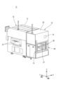
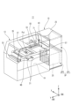
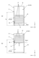
図1から図3を参照して印刷装置11の概要について説明する。印刷装置11は、スクリーン印刷装置と読み替えられてもよい。図1は、本実施の形態に係るマスクチェンジャ15を備えた印刷装置11の斜視図である。図2は、本実施の形態に係る印刷装置11の一部透視斜視図である。図3は、本実施の形態に係る印刷装置11の透視側面図である。
(Present embodiment)
<Configuration of Printing Device>
An overview of a printing apparatus 11 will be described with reference to Fig. 1 to Fig. 3. The printing apparatus 11 may be read as a screen printing apparatus. Fig. 1 is a perspective view of the printing apparatus 11 equipped with a mask changer 15 according to the present embodiment. Fig. 2 is a partially transparent perspective view of the printing apparatus 11 according to the present embodiment. Fig. 3 is a transparent side view of the printing apparatus 11 according to the present embodiment.

印刷装置11は、印刷部13と、マスクチェンジャ15と、を備える。 The printing device 11 includes a printing unit 13 and a mask changer 15.

印刷部13は、マスク27を用いて、印刷対象物としての基板KB(図2参照)の上面に、半田ペーストPst(図2参照)を印刷する。マスク27は、スクリーンマスク又はメタルマスクと読み替えられてもよい。印刷部13は、当該印刷部13を覆う印刷部カバー17と、基板搬送保持部21と、を有する。基板搬送保持部21は、基板KBを搬送すると共に、印刷位置にて基板KBを保持する。 The printing unit 13 uses a mask 27 to print solder paste Pst (see FIG. 2) on the top surface of the substrate KB (see FIG. 2) as the printing target. The mask 27 may be interpreted as a screen mask or a metal mask. The printing unit 13 has a printing unit cover 17 that covers the printing unit 13, and a substrate transport and holding unit 21. The substrate transport and holding unit 21 transports the substrate KB and holds the substrate KB at the printing position.

マスクチェンジャ15は、印刷部13の後部に隣接して設けられ、印刷部13にて使用されるマスク27をマガジン25から印刷部13に搬入したり、印刷部13にて使用されたマスク27を印刷部13からマガジン25に搬出したりする。なお、マスクチェンジャ15の詳細については後述する。 The mask changer 15 is provided adjacent to the rear of the printing unit 13, and transports masks 27 used in the printing unit 13 from the magazine 25 to the printing unit 13, and transports masks 27 used in the printing unit 13 from the printing unit 13 to the magazine 25. Details of the mask changer 15 will be described later.

マスクチェンジャ15の筐体23の後面側の上部に、例えば印刷部13で何らかのエラーが発生した場合等に警報音を発生させる発報部が設けられてよい。発報部は、例えばLED等を備えたタッチパネル31であってよい。ただし、発報部は、これに限定されず、例えば印刷装置11の印刷部カバー17または筐体23上に設けられたランプといった他の報知手段であってもよい。 An alarm unit that generates an alarm sound when, for example, an error occurs in the printing unit 13 may be provided at the top of the rear side of the housing 23 of the mask changer 15. The alarm unit may be, for example, a touch panel 31 equipped with an LED or the like. However, the alarm unit is not limited to this and may be other notification means such as a lamp provided on the printing unit cover 17 or housing 23 of the printing device 11.

次に、図2および図3を参照して、印刷装置11の内部構造について説明する。 Next, the internal structure of the printing device 11 will be described with reference to Figures 2 and 3.

印刷部13において、基板搬送保持部21の上方に、マスクガイド33が設けられる。
印刷部13において、マスクガイド33の上方に、マスク保持部35が配置される。マスク保持部35の上方に、印刷ヘッド37、スクレイパユニット39、マスク上面クリーナ41、及び、気体吹付け部43が設けられる。加えて、マスク保持部35の上方に、左右(X軸方向)に沿って配置された2つのマスク保持部昇降シリンダ45のそれぞれと、前後左右の4つのマスク保持部押さえシリンダ47のそれぞれとが設けられる。
In the printing unit 13 , a mask guide 33 is provided above the substrate transport and holding unit 21 .
In the printing unit 13, a mask holding unit 35 is disposed above the mask guide 33. A print head 37, a scraper unit 39, a mask upper surface cleaner 41, and a gas blowing unit 43 are provided above the mask holding unit 35. In addition, two mask holding unit lifting cylinders 45 arranged along the left and right (X-axis direction) and four mask holding unit pressing cylinders 47 on the front, back, left and right are provided above the mask holding unit 35.

2つのマスク保持部昇降シリンダ45のそれぞれ、及び、4つのマスク保持部押さえシリンダ47のそれぞれは、マスクガイド33の左右に設けられた前後方向ガイド部(図示しない)が有する垂直部に固定して設けられる。加えて、2つのマスク保持部昇降シリンダ45のそれぞれは、マスク保持部35においてY軸方向に延びる左右の2つの直線部分の中間部の上方に設けられる。加えて、4つのマスク保持部押さえシリンダ47のそれぞれは、マスク保持部35の四隅又はその近傍の上方に設けられる。 Each of the two mask holder lifting cylinders 45 and each of the four mask holder pressing cylinders 47 are fixed to the vertical portions of the front-rear direction guide portions (not shown) provided on the left and right sides of the mask guide 33. In addition, each of the two mask holder lifting cylinders 45 is provided above the middle portions of the two left and right straight portions extending in the Y-axis direction in the mask holder 35. In addition, each of the four mask holder pressing cylinders 47 is provided above the four corners of the mask holder 35 or in the vicinity thereof.

マスク保持部35の下方に、マスク移動機構49及びカメラ51と、マスク下面クリーナ53とが設けられる。 A mask moving mechanism 49, a camera 51, and a mask underside cleaner 53 are provided below the mask holding section 35.

気体吹付け部43は、印刷工程の実行によりマスク27がペーストPstで汚れる前にマスク27の上面をクリーニングするマスククリーナとして機能する。マスク27がペーストPstで汚れる前の例として、マスク27の使用前、あるいは、マスク27に最初のペーストPstが供給される前が挙げられる。気体吹付け部43は、マスク27が搬送されるマスクガイド33の上方に、マスク27の搬送方向(Y軸方向)に対してほぼ直行して交差する横方向(つまりX軸方向)に延びた管状部55と、管状部55の一端側に繋がるバルブ部57とを備える。管状部55は、2つの前後方向ガイド部(図示しない)のそれぞれの後端側に、2つの前後方向ガイド部のそれぞれを跨ぐようにして設けられる。 The gas blowing unit 43 functions as a mask cleaner that cleans the upper surface of the mask 27 before the mask 27 becomes contaminated with the paste Pst due to the execution of the printing process. Examples of the time before the mask 27 becomes contaminated with the paste Pst include before the mask 27 is used, or before the first paste Pst is supplied to the mask 27. The gas blowing unit 43 includes a tubular portion 55 that extends in a horizontal direction (i.e., the X-axis direction) that intersects the transport direction (the Y-axis direction) of the mask 27 and is approximately perpendicular to the transport direction of the mask 27 above the mask guide 33 along which the mask 27 is transported, and a valve portion 57 that is connected to one end of the tubular portion 55. The tubular portion 55 is provided on the rear end side of each of the two front-rear guide portions (not shown) so as to straddle each of the two front-rear guide portions.

マスク下面クリーナ53は、マスク下面クリーナガイド(図示しない)によって、マスクガイド33の下方の領域を、Y軸方向に移動自在に設けられる。マスク下面クリーナ53は、移動ベース連結部(図示しない)によって、マスク移動機構49の移動ベース59と連結され、移動ベース59と一体となってY軸方向に移動してマスク27の下面をクリーニングする。マスク下面クリーナ53は、移動ベース59によってY軸方向に移動されない場合、マスク搬送位置の前方のクリーナ待機位置に位置して待機する(図2参照)。マスク下面クリーナ53は、上述したマスク下面クリーナガイド(図示しない)に設けられた下面クリーナ昇降部(図示しない)によって、マスクガイド33に対して(すなわち搬送位置に設置されたマスク27に対して)昇降自在となっている。 The mask underside cleaner 53 is provided so as to be movable in the Y-axis direction in the area below the mask guide 33 by a mask underside cleaner guide (not shown). The mask underside cleaner 53 is connected to the moving base 59 of the mask moving mechanism 49 by a moving base connecting part (not shown) and moves in the Y-axis direction together with the moving base 59 to clean the underside of the mask 27. When the mask underside cleaner 53 is not moved in the Y-axis direction by the moving base 59, it waits at a cleaner waiting position in front of the mask transport position (see FIG. 2). The mask underside cleaner 53 is movable up and down relative to the mask guide 33 (i.e., relative to the mask 27 placed at the transport position) by a lower cleaner lifting part (not shown) provided on the above-mentioned mask underside cleaner guide (not shown).

マスク移動機構49は、マスクチェンジャ15が備えるマガジン25と所定のマスク搬送位置との間でマスク27を移動させる機能を有する。具体的に、マスク移動機構49は、マガジン25に収納されたマスク27を引き出して印刷部13内の所定のマスク搬送位置までマスク27を移動させる。また、マスク移動機構49は、所定のマスク搬送位置に位置するマスク27を移動させて、マガジン25内に戻す(収納する)。マスク移動機構49は、X軸方向に延びて設けられた移動ベース59、及び、移動ベース59に設けられた昇降アクチュエータ61によって昇降自在な、引出しプレート63を備える。なお、マスク移動機構49は、マガジン25から印刷部13へマスク27(搬入マスク)を移送する、及び、印刷部13からマガジン25へマスク27(搬出マスク)を移送するマスク移送部と読み替えられてもよい。 The mask moving mechanism 49 has a function of moving the mask 27 between the magazine 25 of the mask changer 15 and a predetermined mask transport position. Specifically, the mask moving mechanism 49 pulls out the mask 27 stored in the magazine 25 and moves the mask 27 to a predetermined mask transport position in the printing unit 13. The mask moving mechanism 49 also moves the mask 27 located at the predetermined mask transport position and returns (stores) it in the magazine 25. The mask moving mechanism 49 includes a moving base 59 extending in the X-axis direction and a pull-out plate 63 that can be raised and lowered by a lifting actuator 61 provided on the moving base 59. The mask moving mechanism 49 may be interpreted as a mask transport unit that transports the mask 27 (incoming mask) from the magazine 25 to the printing unit 13 and transports the mask 27 (outgoing mask) from the printing unit 13 to the magazine 25.

<マスチェンジャの構成>
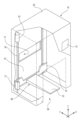
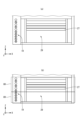
図4および図5を参照して、マスクチェンジャ15について説明する。図4は、本実施の形態に係るマスクチェンジャ15における筐体23の透視斜視図である。図5は、本実施の形態に係るマスクチェンジャ15における筐体23の透視側面図である。図5(a)は、マガジン25がマスク供給位置である供給空間SP1に位置した場合の筐体23の透視斜視図である。図5(b)は、マガジン25がマガジン供給位置である作業空間SP2に位置した場合の筐体23の透視斜視図である。
<Mass changer configuration>
The mask changer 15 will be described with reference to Figures 4 and 5. Figure 4 is a perspective view of the housing 23 in the mask changer 15 according to this embodiment. Figure 5 is a perspective side view of the housing 23 in the mask changer 15 according to this embodiment. Figure 5(a) is a perspective view of the housing 23 when the magazine 25 is located in the supply space SP1, which is the mask supply position. Figure 5(b) is a perspective view of the housing 23 when the magazine 25 is located in the working space SP2, which is the magazine supply position.

マスクチェンジャ15は、筐体23と、マガジン25と、昇降機65と、タッチパネル31と、を備えて構成される。昇降機65は、移動部の一例である。 The mask changer 15 is configured with a housing 23, a magazine 25, an elevator 65, and a touch panel 31. The elevator 65 is an example of a moving part.

マガジン25は、前後方向に開口した略直方体形状を有する。マガジン25の内部には、上下方向に並んだ複数の棚段26が設けられる。複数の棚段26のそれぞれに、マスク27が水平姿勢で載置(収納)される。マガジン25には、基板KBの品種に応じた異なる複数種類(複数枚)のマスク27のそれぞれが収納される。このように、マガジン25は、マスク27をY軸方向に挿抜自在に収納可能な構成となっている。 The magazine 25 has a generally rectangular parallelepiped shape that is open in the front-to-rear direction. Inside the magazine 25, a plurality of shelves 26 are arranged in the vertical direction. Masks 27 are placed (stored) in a horizontal position on each of the plurality of shelves 26. The magazine 25 stores a plurality of different types (multiple pieces) of masks 27 corresponding to the type of substrate KB. In this way, the magazine 25 is configured to store the masks 27 so that they can be freely inserted and removed in the Y-axis direction.

マスクチェンジャ15は、作業者がマスク27の供給作業を行うための開口部29を有する。マスクチェンジャ15における筐体23の内部空間SPは、図2および図3に示すように、上方空間が供給空間SP1となっており、下方空間が作業空間SP2となっている。 The mask changer 15 has an opening 29 through which an operator supplies the mask 27. As shown in Figures 2 and 3, the upper space of the internal space SP of the housing 23 of the mask changer 15 is the supply space SP1, and the lower space is the working space SP2.

供給空間SP1は、マガジン25に収納されたマスク27をマスク通過開口71を介して印刷部13に供給する場合に、マガジン25が位置する空間である。作業空間SP2は、マガジン25又はマガジン25に収納された1枚以上のマスク27を作業者が供給する場合に、マガジン25が位置する空間である。 The supply space SP1 is the space in which the magazine 25 is located when the masks 27 stored in the magazine 25 are supplied to the printing unit 13 through the mask passage opening 71. The working space SP2 is the space in which the magazine 25 is located when an operator supplies the magazine 25 or one or more masks 27 stored in the magazine 25.

筐体23における作業空間SP2にアクセス可能な位置に、開口部29が形成される。また、筐体23の前面側に、マスク通過開口71が設けられる。マスク通過開口71は、供給空間SP1が印刷部13の内部(つまり、印刷部カバー17の内部)と連通するように設けられる。また、マスク通過開口71は、マスク27が前後方向に通過可能な大きさを有する。 An opening 29 is formed at a position in the housing 23 that allows access to the working space SP2. A mask passing opening 71 is also provided on the front side of the housing 23. The mask passing opening 71 is provided so that the supply space SP1 communicates with the interior of the printing unit 13 (i.e., the interior of the printing unit cover 17). The mask passing opening 71 is also large enough to allow the mask 27 to pass through in the front-rear direction.

図3に示すマスク移動機構49は、マガジン25のいずれかの棚段26(図6及び図7参照)に収納された、印刷部13に搬入するマスク27(搬入マスクと称する)を、マスク通過開口71から前方へ引き出して所定のマスク搬送位置まで搬送する。また、マスク移動機構49は、マスク搬送位置に搬送されたマスク27(搬出マスクと称する)を、マスク通過開口71からマガジン25(詳細にはマガジン25のいずれかの棚段26)に収納する(戻す)。 The mask moving mechanism 49 shown in FIG. 3 pulls out the mask 27 (referred to as an input mask) stored in one of the shelves 26 of the magazine 25 (see FIG. 6 and FIG. 7) to be loaded into the printing unit 13 forward through the mask passing opening 71 and transports it to a predetermined mask transport position. The mask moving mechanism 49 also stores (returns) the mask 27 (referred to as an output mask) that has been transported to the mask transport position through the mask passing opening 71 into the magazine 25 (specifically, one of the shelves 26 of the magazine 25).

昇降機65は、略矩形状に形成され、マガジン25の底面を下方から支持する昇降体73と、X軸方向に延びて昇降体73を支持する昇降体支持部75と、昇降体支持部75の一端側に設けられたナット部77と、ナット部77に螺合して上下方向に延びたボール螺子79と、ボール螺子79を回転駆動させる昇降体昇降モータ81とにより構成される。 The elevator 65 is formed in a roughly rectangular shape and is composed of an elevator body 73 that supports the bottom surface of the magazine 25 from below, an elevator body support part 75 that extends in the X-axis direction and supports the elevator body 73, a nut part 77 provided on one end side of the elevator body support part 75, a ball screw 79 that screws into the nut part 77 and extends in the vertical direction, and an elevator body lifting motor 81 that rotates and drives the ball screw 79.

昇降機65は、昇降体昇降モータ81の作動によりボール螺子79が所定の方向に回転し、この回転によりナット部77に連結されて一体的に構成された昇降体支持部75が昇降する。これにより、昇降機65は、昇降体支持部75に連結された昇降体73と、昇降体73が支持するマガジン25とを、供給空間SP1と作業空間SP2との間にわたって昇降させる。すなわち、昇降機65は、作業者により筐体23の開口部29から搬入されたマガジン25を、筐体23の開口部29が設けられた作業空間SP2と、その開口部29から離れた供給空間SP1との間で移動させるマガジン25の移動(昇降)機構として機能する。つまり、昇降機65は、マガジン供給位置Mgspと任意のマスク供給位置Mssp1との間でマガジン25を移動(昇降)させることができる。 The elevator 65 rotates the ball screw 79 in a predetermined direction by the operation of the elevator body lifting motor 81, and this rotation lifts and lowers the elevator body support part 75, which is connected to the nut part 77 and configured as an integral part. As a result, the elevator 65 lifts and lowers the elevator body 73 connected to the elevator body support part 75 and the magazine 25 supported by the elevator body 73 between the supply space SP1 and the working space SP2. In other words, the elevator 65 functions as a magazine 25 movement (lifting) mechanism that moves the magazine 25, which is brought in by the worker through the opening 29 of the housing 23, between the working space SP2 where the opening 29 of the housing 23 is provided and the supply space SP1 away from the opening 29. In other words, the elevator 65 can move (lift) the magazine 25 between the magazine supply position Mgsp and an arbitrary mask supply position Mssp1.

昇降体73は、昇降体昇降モータ81の作動方向(すなわち、ボール螺子79の回転方向)に応じて上昇又は下降する。昇降体73が筐体23内における作業空間SP2の下降限度位置(つまり、図5(b)に示すマガジン供給位置)にある場合、作業者は、開口部29からマガジン25を筐体23内に入れて、昇降体73の上面に載置できる。また、昇降体73が下降限度位置にある場合、作業者は、昇降体73に載置されたマガジン25を開口部29から取り出すことができる。 The lifting body 73 rises or falls depending on the operating direction of the lifting body lifting motor 81 (i.e., the rotation direction of the ball screw 79). When the lifting body 73 is at the lowest limit position of the working space SP2 in the housing 23 (i.e., the magazine supply position shown in FIG. 5(b)), the worker can insert the magazine 25 into the housing 23 through the opening 29 and place it on the top surface of the lifting body 73. Also, when the lifting body 73 is at the lowest limit position, the worker can remove the magazine 25 placed on the lifting body 73 from the opening 29.

昇降機65は、昇降体昇降モータ81を駆動させて、マガジン供給位置にてセットされたマガジン25を載せた昇降体73を上昇させる。このとき、昇降機65は、搬入マスク83がマスク通過開口71から取り出すことができる所定の作業高さHsとなるように、昇降体73の移動量を調整する。所定の作業高さHsは、マスク通過開口71を通じてマスク移動機構49がマガジン25に収納された搬入マスク83を取り出し可能な高さであってよい。図5(b)は、搬入マスク83が所定の作業高さHsに位置した状態を示している。なお、所定の作業高さHsの位置は、マスク供給位置Mssp1に等しくてよい。 The elevator 65 drives the elevator body lifting motor 81 to raise the elevator body 73 carrying the magazine 25 set at the magazine supply position. At this time, the elevator 65 adjusts the movement amount of the elevator body 73 so that the incoming mask 83 is at a predetermined working height Hs at which it can be removed from the mask passing opening 71. The predetermined working height Hs may be a height at which the mask moving mechanism 49 can remove the incoming mask 83 stored in the magazine 25 through the mask passing opening 71. FIG. 5(b) shows a state in which the incoming mask 83 is located at the predetermined working height Hs. The position of the predetermined working height Hs may be equal to the mask supply position Mssp1.

<コードリーダ、光学センサ及び二次元コード>
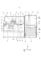
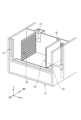
図6及び図7を参照して、コードリーダ87、光学センサ85及び二次元コード86の位置について説明する。図6は、本実施の形態に係るコードリーダ87及び光学センサ85の位置を示す一部透視斜視図である。図7は、本実施の形態に係るマスク27における二次元コード86の位置を示す図である。
<Code readers, optical sensors and two-dimensional codes>
The positions of the code reader 87, the optical sensor 85, and the two-dimensional code 86 will be described with reference to Figures 6 and 7. Figure 6 is a partially transparent perspective view showing the positions of the code reader 87 and the optical sensor 85 according to this embodiment. Figure 7 is a diagram showing the position of the two-dimensional code 86 on the mask 27 according to this embodiment.

図6に示すように、光学センサ85は、印刷部13における、マガジン25に収納されたマスク27の印刷部13側の側面に対して光を照射可能な位置に設けられる。例えば、光学センサ85は、マガジン25を搭載した昇降体73を最も下降させた状態(例えば下降限度位置)において、マガジン25の最も上段の棚段26に収納されたマスク27の印刷部13側の側面に対して光を照射可能な位置に設けられる。光学センサ85は、光を照射してその反射光の有無を検出することにより、マガジン25の各棚段26にマスク27が収納されているか否かを検出する。 As shown in FIG. 6, the optical sensor 85 is provided at a position in the printing unit 13 where it can irradiate light onto the side of the mask 27 stored in the magazine 25 facing the printing unit 13. For example, the optical sensor 85 is provided at a position where it can irradiate light onto the side of the mask 27 stored on the uppermost shelf 26 of the magazine 25 facing the printing unit 13 when the lifting body 73 carrying the magazine 25 is lowered to the lowest position (e.g., at the lowest position). The optical sensor 85 detects whether a mask 27 is stored on each shelf 26 of the magazine 25 by irradiating light and detecting the presence or absence of reflected light.

図6に示すように、コードリーダ87は、印刷部13における、マガジン25に収納されたマスク27の印刷部13側の側面を撮像可能な位置に設けられる。例えば、コードリーダ87は、マガジン25を搭載した昇降体73を最も下降させた状態において、マガジン25の最も上段の棚段26に収納されたマスク27の印刷部13側の側面を撮像可能な位置に設けられる。すなわち、コードリーダ87と光学センサ85とは、ほぼ同じ高さの位置に設けられてよい。 As shown in FIG. 6, the code reader 87 is provided at a position in the printing unit 13 where it can image the side of the mask 27 stored in the magazine 25 facing the printing unit 13. For example, the code reader 87 is provided at a position where it can image the side of the mask 27 stored on the uppermost shelf 26 of the magazine 25 facing the printing unit 13 when the lifting body 73 carrying the magazine 25 is lowered to its lowest position. In other words, the code reader 87 and the optical sensor 85 may be provided at approximately the same height.

図7に示すように、二次元コード86は、マスク27の印刷部13側の側面であって、棚段26に収納された状態のマスク27のX軸方向において図6に示すコードリーダ87と対向する位置に付与される。二次元コード86の例として、QRコード(登録商標)が挙げられる。この場合、コードリーダ87は、QRコードリーダであってよい。なお、マスク27には、二次元コード86に代えて、バーコードが付与されてもよいし、一意に識別可能な数字又は文字の列が付与されてもよい。二次元コード又はバーコードは、コードが印刷された粘着テープなどをマスク27の側面に貼付することによって、マスク27に固着されてよい。または、二次元コード又はバーコードは、コードが印刷されたマグネットシートをマスク27の側面に貼付することによって、マスク27に固着されてよい。 7, the two-dimensional code 86 is attached to the side of the mask 27 facing the printing unit 13, at a position facing the code reader 87 shown in FIG. 6 in the X-axis direction of the mask 27 stored on the shelf 26. An example of the two-dimensional code 86 is a QR code (registered trademark). In this case, the code reader 87 may be a QR code reader. Note that instead of the two-dimensional code 86, a barcode or a uniquely identifiable string of numbers or letters may be attached to the mask 27. The two-dimensional code or barcode may be fixed to the mask 27 by attaching an adhesive tape or the like on which the code is printed to the side of the mask 27. Alternatively, the two-dimensional code or barcode may be fixed to the mask 27 by attaching a magnetic sheet on which the code is printed to the side of the mask 27.

これにより、マガジン25を搭載した昇降体73を最も下降させた状態から上昇させることで、光学センサ85は、マガジン25の各棚段26におけるマスク27の有無を検出することができ、コードリーダ87は、マガジン25の各棚段26に収納されたマスク27の二次元コード96を読み取ることができる。なお、コードリーダ87は、二次元コード86に代表されるコードを読み取り可能な読取部と読み替えられてもよい。 As a result, by raising the lifting body 73 carrying the magazine 25 from its lowest position, the optical sensor 85 can detect the presence or absence of a mask 27 on each shelf 26 of the magazine 25, and the code reader 87 can read the two-dimensional code 96 of the mask 27 stored on each shelf 26 of the magazine 25. The code reader 87 may also be interpreted as a reading unit capable of reading codes such as the two-dimensional code 86.

二次元コード86は、マスク27毎に異なるものであってよい。制御部93は、二次元コード86とマスク27の種類との対応関係を示す情報を予め保持してよい。これにより、コードリーダ87によってマスク27の二次元コード86を読み取ることにより、制御部93は、そのマスク27の種類を認識することができる。 The two-dimensional code 86 may be different for each mask 27. The control unit 93 may hold information indicating the correspondence between the two-dimensional code 86 and the type of mask 27 in advance. This allows the control unit 93 to recognize the type of mask 27 by reading the two-dimensional code 86 of the mask 27 with the code reader 87.

<制御部の構成>
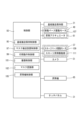
次に、図8を参照して、本実施の形態に係る印刷装置11の制御部93について説明する。図8は、本実施の形態に係る印刷装置11の制御部93を示すブロック図である。
<Configuration of control unit>
Next, the control unit 93 of the printing device 11 according to the present embodiment will be described with reference to Fig. 8. Fig. 8 is a block diagram showing the control unit 93 of the printing device 11 according to the present embodiment.

印刷装置11が備える制御部93は、基板搬送保持制御部95と、マスク搬送設置制御部97と、印刷動作制御部99と、撮像制御部101と、昇降機制御部105と、を含んで構成される。 The control unit 93 of the printing device 11 includes a substrate transport/holding control unit 95, a mask transport/installation control unit 97, a printing operation control unit 99, an imaging control unit 101, and an elevator control unit 105.

制御部93は、例えばCPU(Central Processing Unit)又はFPGA(Field Programmable Gate Array)を用いて構成されて、印刷部13が備えるメモリ(図示しない)と協働して、各種処理及び制御を行う。具体的には、制御部93はメモリに保持されたプログラムおよびデータを参照し、そのプログラムを実行することにより、各部の機能を実現する。 The control unit 93 is configured using, for example, a CPU (Central Processing Unit) or an FPGA (Field Programmable Gate Array), and performs various processes and controls in cooperation with a memory (not shown) provided in the printing unit 13. Specifically, the control unit 93 references the programs and data stored in the memory, and executes the programs to realize the functions of each unit.

基板搬送保持制御部95は、所定の基板搬送位置まで基板KBを搬送し、基板搬送保持部21によって搬送された基板KBを保持する。また、基板搬送保持制御部95は、カメラ51により撮像された基板KBの撮像画像に基づいて、所定の基板搬送位置で保持された基板KBがマスク27のマスク搬送位置に対して位置ずれがあると判定した場合、保持された基板KBの位置合わせを行う。 The substrate transport and holding control unit 95 transports the substrate KB to a predetermined substrate transport position and holds the substrate KB transported by the substrate transport and holding unit 21. Furthermore, when the substrate transport and holding control unit 95 determines, based on the image of the substrate KB captured by the camera 51, that the substrate KB held at the predetermined substrate transport position is misaligned with respect to the mask transport position of the mask 27, it aligns the held substrate KB.

マスク搬送設置制御部97は、マスク移動機構49を制御してマガジン25に収納されたマスク27(搬入マスク)を取り出し、所定のマスク搬送位置までマスク27を搬送して保持する。詳細には、マスク搬送設置制御部97は、移動ベース駆動モータ107による移動ベース59のY軸方向への移動制御と、昇降アクチュエータ61による引出しプレート63の昇降制御と、張力付与シリンダ(図示しない)によるマスク設置位置に位置したマスク27への張力付与制御等を実行する。 The mask transport/installation control unit 97 controls the mask moving mechanism 49 to retrieve the mask 27 (input mask) stored in the magazine 25, and transports and holds the mask 27 to a predetermined mask transport position. In detail, the mask transport/installation control unit 97 controls the movement of the moving base 59 in the Y-axis direction by the moving base drive motor 107, controls the elevation of the pull-out plate 63 by the elevation actuator 61, and controls the application of tension to the mask 27 positioned at the mask installation position by a tensioning cylinder (not shown).

印刷動作制御部99は、印刷ヘッド37を駆動させて、マスク27の下面と接触する基板KBへのペーストPstの印刷動作制御を行う。詳細には、印刷動作制御部99は、スキージベース駆動モータ109によるスキージベース(図示しない)のY軸方向への移動制御と、スキージ昇降駆動部111によるスキージの昇降制御とを実行する。 The printing operation control unit 99 drives the print head 37 to control the printing operation of the paste Pst onto the substrate KB that is in contact with the lower surface of the mask 27. In detail, the printing operation control unit 99 controls the movement of the squeegee base (not shown) in the Y-axis direction by the squeegee base drive motor 109, and controls the elevation of the squeegee by the squeegee elevation drive unit 111.

撮像制御部101は、基板搬送保持部21によって所定の基板搬送位置にて保持された基板KBの上面と、マスク搬送位置に設置されたマスク27の下面とのそれぞれをカメラ51で撮像するための制御を実行する。詳細には、撮像制御部101は、移動ベース駆動モータ107による移動ベース59のY軸方向への移動制御と、移動ベース59に沿ったカメラ51のX軸方向への移動制御と、カメラ51が備える下方撮像カメラ(図示しない)の下方の領域に位置する基板KBの上面の撮像制御と、カメラ51が備える上方撮像カメラ(図示しない)の上方の領域に位置するマスク27の下面の撮像制御とを実行する。 The imaging control unit 101 executes control for imaging, with the camera 51, the upper surface of the substrate KB held at a predetermined substrate transport position by the substrate transport holding unit 21, and the lower surface of the mask 27 placed at the mask transport position. In detail, the imaging control unit 101 executes control for moving the movable base 59 in the Y-axis direction by the movable base drive motor 107, control for moving the camera 51 in the X-axis direction along the movable base 59, control for imaging the upper surface of the substrate KB located in the area below the lower imaging camera (not shown) provided in the camera 51, and control for imaging the lower surface of the mask 27 located in the area above the upper imaging camera (not shown) provided in the camera 51.

マスク認識部102は、光学センサ85及びコードリーダ87を制御して、マガジン25の各棚段26におけるマスク27の有無及びマスク27の種類を認識し、マガジン内マスク情報103を生成する。なお、マガジン内マスク情報103の詳細については後述する(図9参照)。 The mask recognition unit 102 controls the optical sensor 85 and the code reader 87 to recognize the presence or absence of a mask 27 on each shelf 26 of the magazine 25 and the type of mask 27, and generates in-magazine mask information 103. Details of the in-magazine mask information 103 will be described later (see FIG. 9).

昇降機制御部105は、昇降体昇降モータ81を駆動させて、昇降機65によるマガジン25の昇降を制御する。 The elevator control unit 105 drives the elevator body lifting motor 81 to control the lifting and lowering of the magazine 25 by the elevator 65.

報知の一例としてのタッチパネル31は、制御部93との間で電気的に接続される。タッチパネル31は、例えばLCD(Liquid Crystal Display)又は有機EL(Electroluminescence)等の表示装置と、入力装置とによって構成されたユーザインターフェースである。 The touch panel 31, which is an example of a notification device, is electrically connected to the control unit 93. The touch panel 31 is a user interface that is configured with a display device, such as an LCD (Liquid Crystal Display) or an organic EL (Electroluminescence), and an input device.

タッチパネル31は、作業者による入力操作を受け付け可能であり、入力操作を電気信号に変換して印刷装置11における制御部93に出力する。 The touch panel 31 can accept input operations by an operator, convert the input operations into electrical signals, and output them to the control unit 93 in the printing device 11.

次に、印刷装置11におけるマスクの供給動作手順例について説明する。作業者は、スクリーン印刷に必要な1枚以上のマスク27が事前に収納されたマガジン25を、マスクチェンジャ15の作業空間SP2の昇降体73上に載置するマガジン供給作業を行う。 Next, an example of the mask supply operation procedure in the printing device 11 will be described. The operator performs the magazine supply operation by placing the magazine 25, which already contains one or more masks 27 required for screen printing, on the lifting body 73 in the working space SP2 of the mask changer 15.

制御部93は、マガジン供給作業完了後に作業者により外カバーが閉じられると、昇降機制御部105により昇降機65を駆動させて、マスク認識部102により、マガジン25に対応するマガジン内マスク情報103を生成する。なお、マガジン内マスク情報103の生成処理の詳細については後述する(図11参照)。 When the outer cover is closed by the operator after the magazine supply operation is completed, the control unit 93 drives the elevator 65 via the elevator control unit 105, and generates in-magazine mask information 103 corresponding to the magazine 25 via the mask recognition unit 102. Details of the process of generating the in-magazine mask information 103 will be described later (see FIG. 11).

制御部93は、搬入マスク27が収納された棚段26の高さがマスク通過開口71に対応する所定の作業高さHsになるようにマガジン25を上昇させる。 The control unit 93 raises the magazine 25 so that the height of the shelf 26 on which the incoming mask 27 is stored is at a predetermined working height Hs corresponding to the mask passage opening 71.

制御部93は、マガジン25の上昇制御後に、マスク移動機構49を駆動させて、マスク通過開口71を介して搬入マスク83を取り出し、所定のマスク搬送位置まで搬送する。具体的には、制御部93は、マスク搬送設置制御部97により移動ベース駆動モータ107を駆動させて、移動ベース59を後方(マスクチェンジャ15側)に移動させる。 After controlling the raising of the magazine 25, the control unit 93 drives the mask moving mechanism 49 to remove the incoming mask 83 through the mask passage opening 71 and transport it to a predetermined mask transport position. Specifically, the control unit 93 drives the moving base drive motor 107 via the mask transport installation control unit 97 to move the moving base 59 backward (towards the mask changer 15).

制御部93は、移動ベース59に取り付けられた引出しプレート63の上面にX軸方向に並んで設けられた2つのマスク移動用係合突起(図示しない)と、マガジン25に収納された搬入マスク27の前縁側に設けられた2つの係合孔(図示しない)とを係合させる。 The control unit 93 engages two mask movement engagement protrusions (not shown) arranged side by side in the X-axis direction on the upper surface of the pull-out plate 63 attached to the moving base 59 with two engagement holes (not shown) provided on the front edge side of the input mask 27 stored in the magazine 25.

制御部93は、2つのマスク移動用係合突起と2つの係合孔とが係合した状態で、移動ベース駆動モータ107を駆動させて、マガジン25内からマスク通過開口71を通過して搬入マスク27を印刷部13の内部に引き出し、搬入マスク27が前方に位置する所定のマスク搬送位置に位置するまで移動させる。これにより、制御部93は、マガジン25内から搬入マスク27を取り出し、所定のマスク搬送位置まで搬送できる。 When the two mask movement engagement protrusions and the two engagement holes are engaged, the control unit 93 drives the movement base drive motor 107 to pull the incoming mask 27 from inside the magazine 25 through the mask passage opening 71 into the interior of the printing unit 13, and moves the incoming mask 27 until it is positioned at a predetermined mask transport position located forward. This allows the control unit 93 to remove the incoming mask 27 from inside the magazine 25 and transport it to the predetermined mask transport position.

なお、移動ベース59により搬送中の搬入マスク27は、その左右の両辺が前後方向に沿って設けられた一対のガイド部の段差(ガイド)によって案内されるので、まっすぐに前方方向へ引き出される。 The input mask 27 being transported by the moving base 59 is guided by a pair of steps (guides) on both its left and right sides that are provided along the front-to-rear direction, so it is pulled out straight forward.

<マガジン内マスク情報>
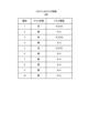
図9を参照して、マガジン内マスク情報103について説明する。図9は、本実施の形態に係るマガジン内マスク情報103の一例を示す図である。
<Mask information in magazine>
The in-magazine mask information 103 will be described with reference to Fig. 9. Fig. 9 is a diagram showing an example of the in-magazine mask information 103 according to the present embodiment.

マガジン内マスク情報103は、マスクチェンジャ15にセットされたマガジン25内の各棚段26に収納されたマスク27に関する情報を含む。 The mask information 103 in the magazine includes information about the masks 27 stored on each shelf 26 in the magazine 25 set in the mask changer 15.

マガジン内マスク情報103は、項目として、棚段26の番号と、当該棚段26にマスク27が収納されているか否かを示すマスク有無と、当該棚段26に収納されているマスクの種類を示すマスク種類とを有する。なお、本実施の形態では、棚段26の番号を上から順に、1、2、3、…として説明するが、棚段26の番号はこれに限られず、例えば、下から順に、1、2、3、…としてもよい。 The mask information 103 in the magazine includes, as items, the number of the shelf 26, mask presence/absence indicating whether or not a mask 27 is stored on the shelf 26, and mask type indicating the type of mask stored on the shelf 26. Note that in this embodiment, the shelf tiers 26 are numbered 1, 2, 3, ... from top to bottom, but the shelf tiers 26 are not limited to this and may be numbered 1, 2, 3, ... from bottom to top.

図9に示すマガジン内マスク情報103の1行目は、1番目の棚段26(棚段「1」)に、マスク27が収納されており(マスク有無「有」)、そのマスク27の種類は「マスクA」(マスク種類「マスクA」)であることを示す。図9に示すマガジン内マスク情報103の2行目は、2番目の棚段26(棚段「2」)に、マスク27が収納されていない(マスク有無「無」)ことを示す。 The first line of the mask information 103 in the magazine shown in FIG. 9 indicates that a mask 27 is stored (mask presence/absence "Present") on the first shelf 26 (shelf "1") and that the type of mask 27 is "Mask A" (mask type "Mask A"). The second line of the mask information 103 in the magazine shown in FIG. 9 indicates that a mask 27 is not stored (mask presence/absence "Absent") on the second shelf 26 (shelf "2").

<第1モード及び第2モード>
図10を参照して、本実施の形態に係る第1モード及び第2モードについて説明する。図10は、本実施の形態に係るLEDボタン19と第1モード及び第2モードとの関係を説明するための図である。
<First mode and second mode>
The first and second modes according to the present embodiment will be described with reference to Fig. 10. Fig. 10 is a diagram for explaining the relationship between the LED button 19 according to the present embodiment and the first and second modes.

図10に示すように、マスクチェンジャ15のマガジン25を搬入及び搬出するための開口部29の横に、マガジン25の棚段26と1対1で対応するLEDボタン19が設けられる。例えば、マガジン25の棚段26の数が10である場合、10個のLEDボタン19が設けられる。 As shown in FIG. 10, LED buttons 19 that correspond one-to-one to the shelves 26 of the magazine 25 are provided next to the opening 29 for loading and unloading the magazine 25 of the mask changer 15. For example, if the number of shelves 26 of the magazine 25 is 10, ten LED buttons 19 are provided.

LEDボタン19は、点灯、消灯、点滅によって、対応する棚段26の状態を示す。制御部93は、第1モードと第2モードとを有し、LEDボタン19の表示態様は、第1モードと第2モードとによって異なってよい。なお、LEDボタン19は、発光部と読み替えられてもよい。 The LED button 19 indicates the state of the corresponding shelf 26 by turning on, off, or blinking. The control unit 93 has a first mode and a second mode, and the display manner of the LED button 19 may differ depending on whether it is the first mode or the second mode. The LED button 19 may also be interpreted as a light-emitting unit.

第1モードは、図10(a)に示すように、マガジン25の各棚段26のすべてを未使用マスク27の搬入及び使用済みマスク27の搬出の両方に使用するモードである。 The first mode, as shown in FIG. 10(a), is a mode in which all of the shelves 26 of the magazine 25 are used for both loading unused masks 27 and unloading used masks 27.

第1モードにおいて、LEDボタン19は、次の(A1)から(A3)の状態を示してよい。 In the first mode, the LED button 19 may indicate the following states (A1) to (A3).

(A1)点灯しているLEDボタン19は、当該LEDボタン19に対応する棚段26にマスク27が収納されていないことを示す。これにより、作業者は、点灯しているLEDボタン19に対応する棚段26にマスク27をセット可能であることを認識できる。 (A1) A lit LED button 19 indicates that a mask 27 is not stored on the shelf 26 that corresponds to that LED button 19. This allows the worker to recognize that a mask 27 can be set on the shelf 26 that corresponds to the lit LED button 19.

(A2)消灯しているLEDボタン19は、当該LEDボタン19に対応する棚段26に未使用マスクが収納されていることを示す。これにより、作業者は、消灯しているLEDボタン19に対応する棚段26に対して特に何もしなくてよいことを認識できる。 (A2) An unlit LED button 19 indicates that an unused mask is stored on the shelf 26 corresponding to that LED button 19. This allows the worker to recognize that he or she does not need to do anything for the shelf 26 corresponding to the unlit LED button 19.

(A3)点滅しているLEDボタン19は、当該LEDボタン19に対応する棚段26に、使用済みマスク27が収納されている又は二次元コード86の読み取りに失敗したマスク27が収納されていることを示す。これにより、作業者は、点滅しているLEDボタン19に対応する棚段26のマスク27を取り出す必要があることを認識する。なお、作業者は、マスク27を取り出した後、点滅しているLEDボタン19を押下する。押下されたLEDボタン19は、点滅から点灯に変化する。これにより、マスク27が取り出されたことを制御部93に認識させることができる。 (A3) A flashing LED button 19 indicates that the shelf 26 corresponding to that LED button 19 contains a used mask 27 or a mask 27 whose two-dimensional code 86 has failed to be read. This allows the worker to recognize that it is necessary to remove the mask 27 from the shelf 26 corresponding to the flashing LED button 19. After removing the mask 27, the worker presses the flashing LED button 19. The pressed LED button 19 changes from flashing to lit. This allows the control unit 93 to recognize that the mask 27 has been removed.

第2モードは、図10(b)に示すように、マガジン25の棚段26を、未使用マスク27の搬入に用いる未使用エリア88と、使用済みマスク27の搬出に用いる使用済みエリア89とに分けて使用するモードである。例えば、上から1段目から6段目を未使用エリア88とし、7段目から10段目を使用済みエリア89とする。この場合、印刷部13は、使用済みマスク27を、使用済みエリア89の何れかの棚段26に搬出し、未使用エリア88の棚段26には搬出しない。 As shown in FIG. 10(b), the second mode is a mode in which the shelves 26 of the magazine 25 are divided into an unused area 88 used for carrying in unused masks 27 and a used area 89 used for carrying out used masks 27. For example, the first to sixth shelves from the top are the unused area 88, and the seventh to tenth shelves are the used area 89. In this case, the printing unit 13 carries out the used masks 27 to one of the shelves 26 in the used area 89, but does not carry out the used masks 27 to the shelf 26 in the unused area 88.

第2モードの未使用エリア88において、LEDボタン19の点灯及び消灯は、上述した第1モードの場合と同様であってよい。 In the unused area 88 of the second mode, the LED button 19 may be turned on and off in the same manner as in the first mode described above.

第2モードの使用済みエリア89において、LEDボタン19は、次の(B1)から(B2)の状態を示してよい。 In the used area 89 in the second mode, the LED button 19 may indicate the following states (B1) to (B2).

(B1)消灯しているLEDボタン19は、当該LEDボタン19に対応する棚段26に使用済みマスク27が収納されていないことを示す。これにより、作業者は、消灯しているLEDボタン19に対応する棚段26に対して特に何もしなくてよいことを認識できる。 (B1) An unlit LED button 19 indicates that no used masks 27 are stored on the shelf 26 corresponding to that LED button 19. This allows the worker to recognize that nothing needs to be done for the shelf 26 corresponding to the unlit LED button 19.

(B2)点滅しているLEDボタン19は、当該LEDボタン19に対応する棚段26に使用済みマスク27が収納されていることを示す。これにより、作業者は、点滅しているLEDボタン19に対応する棚段26の使用済みマスク27を取り出す必要があることを認識する。 (B2) A flashing LED button 19 indicates that a used mask 27 is stored on the shelf 26 corresponding to that LED button 19. This allows the worker to recognize that it is necessary to remove the used mask 27 from the shelf 26 corresponding to the flashing LED button 19.

なお、制御部93は、作業者から、第1モードと第2モードの切り替えを受け付ける操作画像を、タッチパネル31等に表示してもよい。また、制御部93は、第2モードにおける未使用エリア88又は使用済みエリア89として使用する棚段26の段数を受け付ける操作画面を、タッチパネル31等に表示してもよい。 The control unit 93 may display, on the touch panel 31 or the like, an operation image that accepts switching between the first mode and the second mode from the worker. The control unit 93 may also display, on the touch panel 31 or the like, an operation screen that accepts the number of shelves 26 to be used as the unused area 88 or the used area 89 in the second mode.

また、上述したLEDボタン19の点灯、点滅、消灯が示す棚段26の状態は一例であり、LEDボタン19の点灯、点滅、消灯は、上述と異なる棚段26の状態を示すように定められてもよい。 The above-mentioned states of the shelf 26 indicated by the lit, blinking, and off states of the LED button 19 are merely examples, and the lit, blinking, and off states of the LED button 19 may be determined to indicate a different state of the shelf 26 than that described above.

<第1モードの処理フロー>
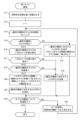
図11を参照しながら、第1モードの場合におけるマスク認識部102の処理について説明する。図11は、本実施の形態に係る第1モードの場合におけるマスク認識部102の処理を示すフローチャートである。なお、マスク認識部102の処理は、制御部93の処理に読み替えられてもよい。
<Processing flow of first mode>
The process of the mask recognition unit 102 in the first mode will be described with reference to Fig. 11. Fig. 11 is a flowchart showing the process of the mask recognition unit 102 in the first mode according to the present embodiment. Note that the process of the mask recognition unit 102 may be replaced with the process of the control unit 93.

マスク認識部102は、昇降体73を初期位置(例えば下降限度位置)に移動させる(S11)。 The mask recognition unit 102 moves the lifting body 73 to an initial position (e.g., the lowest position) (S11).

マスク認識部102は、変数nに1を代入する(S12)。 The mask recognition unit 102 assigns 1 to the variable n (S12).

マスク認識部102は、光学センサ85を制御して、n番目の棚段26のマスク27の有無をセンシングする(S13)。 The mask recognition unit 102 controls the optical sensor 85 to sense the presence or absence of a mask 27 on the nth shelf 26 (S13).

マスク認識部102は、光学センサ85の検出結果に基づいて、n番目の棚段26にマスク27が有るか否かを判定する(S14)。 The mask recognition unit 102 determines whether or not a mask 27 is present on the nth shelf 26 based on the detection result of the optical sensor 85 (S14).

n番目の棚段26にマスク27が無い場合(S14:NO)、マスク認識部102は、n番目の棚段26に対応するLEDボタン19を点灯させ、マガジン内マスク情報103の棚段nのマスク有無の項目に「無」をセットする(S15)。そして、マスク認識部102は、処理をステップS22に進める。 If there is no mask 27 on the nth shelf 26 (S14: NO), the mask recognition unit 102 turns on the LED button 19 corresponding to the nth shelf 26 and sets the mask presence/absence item for shelf n in the mask information 103 in the magazine to "absent" (S15). The mask recognition unit 102 then advances the process to step S22.

n番目の棚段26にマスク27が有る場合(S14:YES)、マスク認識部102は、コードリーダ87を制御して、n番目の棚段26のマスク27に付与されている二次元コード86を読み取る(S16)。 If there is a mask 27 on the nth shelf 26 (S14: YES), the mask recognition unit 102 controls the code reader 87 to read the two-dimensional code 86 attached to the mask 27 on the nth shelf 26 (S16).

マスク認識部102は、二次元コード86の読み取りに成功したか否かを判定する(S17)。 The mask recognition unit 102 determines whether or not the two-dimensional code 86 has been successfully read (S17).

二次元コード86の読み取りに失敗した場合(S17:NO)、マスク認識部102は、n番目の棚段26に対応するLEDボタン19を点滅させ(S18)、処理をステップS22に進める。 If reading of the two-dimensional code 86 fails (S17: NO), the mask recognition unit 102 blinks the LED button 19 corresponding to the nth shelf 26 (S18) and proceeds to step S22.

二次元コード86の読み取りに成功した場合(S17:YES)、マスク認識部102は、n番目の棚段26のマスク27は未使用であるか否かを判定する(S19)。例えば、マスク認識部102は、一度も印刷部13に搬入されていないマスク27を未使用と判定し、印刷部13から搬出されてきたマスク27を使用済みと判定する。 If the reading of the two-dimensional code 86 is successful (S17: YES), the mask recognition unit 102 determines whether the mask 27 on the nth shelf 26 is unused (S19). For example, the mask recognition unit 102 determines that a mask 27 that has never been brought into the printing unit 13 is unused, and determines that a mask 27 that has been brought out of the printing unit 13 is used.

n番目の棚段26のマスク27が使用済みである場合(S19:NO)、マスク認識部102は、n番目の棚段26に対応するLEDボタン19を点滅させ(S18)、処理をステップS22に進める。 If the mask 27 on the nth shelf 26 has been used (S19: NO), the mask recognition unit 102 blinks the LED button 19 corresponding to the nth shelf 26 (S18) and proceeds to step S22.

n番目の棚段26のマスク27が未使用である場合(S19:YES)、マスク認識部102は、マガジン内マスク情報103において、棚段nのマスク有無の項目に「有」をセットし、棚段nのマスク種別の項目に、二次元コード86が示すマスク種別をセットする(S20)。二次元コード86とマスク種別との対応関係を示す情報は、制御部93の所定のメモリに予め格納されてよい。 If the mask 27 on the nth shelf 26 is unused (S19: YES), the mask recognition unit 102 sets the mask presence/absence field for shelf n to "Present" in the mask information in magazine 103, and sets the mask type indicated by the two-dimensional code 86 to the mask type field for shelf n (S20). Information indicating the correspondence between the two-dimensional code 86 and the mask type may be stored in advance in a predetermined memory of the control unit 93.

マスク認識部102は、n番目の棚段26に対応するLEDボタン19を消灯させる(S21)。 The mask recognition unit 102 turns off the LED button 19 corresponding to the nth shelf 26 (S21).

ステップS22として、マスク認識部102は、マガジン25内のすべての棚段26について処理を完了したか否かを判定する(S22)。 In step S22, the mask recognition unit 102 determines whether processing has been completed for all shelves 26 in the magazine 25 (S22).

まだ未処理の棚段26が残っている場合(S22:NO)、マスク認識部102は、変数nに1を加算し、昇降体73を棚段26の1つ分上昇させる(S23)。そして、マスク認識部102は、処理をステップS13に戻す。 If there are still unprocessed shelves 26 remaining (S22: NO), the mask recognition unit 102 adds 1 to the variable n and raises the lifting body 73 by one shelf 26 (S23). The mask recognition unit 102 then returns the process to step S13.

すべての棚段26について処理を完了した場合(S22:YES)、マスク認識部102は、本処理を終了する。 If processing has been completed for all shelves 26 (S22: YES), the mask recognition unit 102 ends this processing.

上述の処理により、マガジン25内の各棚段26におけるマスク27の有無及びマスク種別を示す情報が、マガジン内マスク情報103にセットされる。印刷部13は、マガジン内マスク情報103のマスク種別を参照して、マガジン25の何れの棚段26に何れのマスク種別のマスク27が収納されているかを認識できる。よって、作業者が、マガジン25の何れの棚段26に何れのマスク種別のマスク27を収納したとしても、印刷部13は、マガジン内マスク情報103を参照して、印刷に用いるマスク種別のマスク27をマガジン25から自動的に引き出すことができる。従来のようにマガジン25の何れの棚段26に何れのマスク種別のマスク27を収納すべきかを作業者に指示する場合、作業者によるマスク27の収納ミスが発生し得るところ、本実施の形態によれば、このようなミスは発生しないので、作業効率が向上する。 By the above-mentioned process, information indicating the presence or absence of masks 27 and the type of masks 27 in each shelf 26 in the magazine 25 is set in the in-magazine mask information 103. The printing unit 13 can recognize which shelf 26 in the magazine 25 stores which type of mask 27 by referring to the mask type in the in-magazine mask information 103. Therefore, even if the worker stores which type of mask 27 in which shelf 26 in the magazine 25, the printing unit 13 can automatically pull out the mask 27 of the mask type to be used for printing from the magazine 25 by referring to the in-magazine mask information 103. When the worker is instructed which shelf 26 in the magazine 25 stores which type of mask 27, as in the conventional method, the worker may make a mistake in storing the mask 27. However, according to the present embodiment, such a mistake does not occur, and the work efficiency is improved.

また、作業者は、各棚段26に対応するLEDボタン19の状態を見て、マガジン25の各棚段26におけるマスク27の有無を、印刷装置11の外から認識できる。 In addition, the operator can check the status of the LED buttons 19 corresponding to each shelf 26 and determine from outside the printing device 11 whether or not a mask 27 is present on each shelf 26 of the magazine 25.

また、二次元コード86の読み取りに失敗したマスク27又は使用済みマスク27が収納されている棚段26に対応するLEDボタン19は点滅するので、作業者は、LEDボタン19が点滅している棚段26のマスク27を取り出せばよいことを一目で認識できる。なお、作業者は、マスク27を取り出した場合、そのマスク27を取り出した棚段26に対応するLEDボタン19を押下する。これにより、制御部93は、作業者によってマスク27が取り出された棚段26を認識できる。この場合、マスク認識部102は、マガジン内マスク情報103における、このマスク27が取り出された棚段26に対応するマスク有無を「無」に変更し、マスク種別を「N/A」に変更してよい。 The LED button 19 corresponding to the shelf 26 storing the mask 27 whose two-dimensional code 86 has failed to be read or the used mask 27 flashes, so the worker can recognize at a glance that he or she should remove the mask 27 from the shelf 26 whose LED button 19 is flashing. When the worker removes the mask 27, he or she presses the LED button 19 corresponding to the shelf 26 from which the mask 27 was removed. This allows the control unit 93 to recognize the shelf 26 from which the worker removed the mask 27. In this case, the mask recognition unit 102 may change the mask presence/absence corresponding to the shelf 26 from which the mask 27 was removed in the mask information 103 in the magazine to "absent" and change the mask type to "N/A."

また、マスク27が収納されていない棚段26に対応するLEDボタン19は点灯するので、作業者は、LEDボタン19が点灯している棚段26にマスク27をセット可能であることを一目で確認できる。また、未使用マスク27が収納されている棚段26に対応するLEDボタン19は消灯するので、作業者は、LEDボタン19が消灯している棚段26のマスク27は取り出さなくてよいことを一目で確認できる。 Also, the LED button 19 corresponding to the shelf 26 where the mask 27 is not stored lights up, so the worker can confirm at a glance that the mask 27 can be set on the shelf 26 where the LED button 19 is lit. Also, the LED button 19 corresponding to the shelf 26 where the unused mask 27 is stored is turned off, so the worker can confirm at a glance that the mask 27 does not need to be removed from the shelf 26 where the LED button 19 is turned off.

<第2モードの処理フロー>
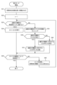
図12を参照しながら、第2モードの場合におけるマスク認識部102の処理について説明する。図12は、本実施の形態に係る第2モードにおけるマスク認識部102の処理を示すフローチャートである。
<Processing flow of second mode>
The process of the mask recognition unit 102 in the second mode will be described with reference to Fig. 12. Fig. 12 is a flowchart showing the process of the mask recognition unit 102 in the second mode according to the present embodiment.

マスク認識部102は、昇降体73を初期位置(例えば下降限度位置)に移動させる(S31)。 The mask recognition unit 102 moves the lifting body 73 to an initial position (e.g., the lowest position) (S31).

マスク認識部102は、変数nに1を代入する(S32)。 The mask recognition unit 102 assigns 1 to the variable n (S32).

マスク認識部102は、n番目の棚段26が未使用エリア88に属するか否かを判定する(S33)。 The mask recognition unit 102 determines whether the nth shelf 26 belongs to the unused area 88 (S33).

n番目の棚段26が未使用エリア88に属する場合(S33:YES)、マスク認識部102は、図11に示すステップS13~S21の処理を実行し(S34)、処理をステップS39に進める。 If the nth shelf 26 belongs to the unused area 88 (S33: YES), the mask recognition unit 102 executes the processing of steps S13 to S21 shown in FIG. 11 (S34), and proceeds to step S39.

n番目の棚段26が使用済みエリア89に属する場合(S33:NO)、マスク認識部102は、次の処理を実行する。 If the nth shelf 26 belongs to the used area 89 (S33: NO), the mask recognition unit 102 executes the following process.

マスク認識部102は、光学センサ85を制御して、n番目の棚段26のマスク27の有無をセンシングする(S35)。 The mask recognition unit 102 controls the optical sensor 85 to sense the presence or absence of a mask 27 on the nth shelf 26 (S35).

マスク認識部102は、光学センサ85の検出結果に基づいて、n番目の棚段26にマスク27が有るか否かを判定する(S36)。 The mask recognition unit 102 determines whether or not a mask 27 is present on the nth shelf 26 based on the detection result of the optical sensor 85 (S36).

n番目の棚段26にマスク27が有る場合(S36:YES)、マスク認識部102は、n番目の棚段26に対応するLEDボタン19を点滅させ(S37)、処理をステップS39に進める。 If there is a mask 27 on the nth shelf 26 (S36: YES), the mask recognition unit 102 blinks the LED button 19 corresponding to the nth shelf 26 (S37) and proceeds to step S39.

n番目の棚段26にマスク27が無い場合(S36:NO)、マスク認識部102は、n番目の棚段26に対応するLEDボタン19を消灯させ(S38)、処理をステップS39に進める。 If there is no mask 27 on the nth shelf 26 (S36: NO), the mask recognition unit 102 turns off the LED button 19 corresponding to the nth shelf 26 (S38) and proceeds to step S39.

ステップS39として、マスク認識部102は、マガジン25内のすべての棚段26について処理を完了したか否かを判定する(S39)。 In step S39, the mask recognition unit 102 determines whether processing has been completed for all shelves 26 in the magazine 25 (S39).

まだ未処理の棚段26が残っている場合(S39:NO)、マスク認識部102は、変数nに1を加算し、昇降体73を棚段26の1つ分上昇させる(S40)。そして、マスク認識部102は、処理をステップS33に戻す。 If there are still unprocessed shelves 26 remaining (S39: NO), the mask recognition unit 102 adds 1 to the variable n and raises the lifting body 73 by one shelf 26 (S40). The mask recognition unit 102 then returns the process to step S33.

すべての棚段26について処理を完了した場合(S39:YES)、マスク認識部102は、本処理を終了する。 If processing has been completed for all shelves 26 (S39: YES), the mask recognition unit 102 ends this processing.

これにより、使用済みエリア89において、使用済みマスク27が収納されている棚段26に対応するLEDボタン19は点滅し、使用済みマスク27が収納されていない棚段26に対応するLEDボタン19は消灯する。よって、作業者は、点滅しているLEDボタン19に対応する棚段26から使用済みマスク27を取り出せばよいことを一目で認識できる。なお、作業者は、使用済みマスク27を取り出した場合、その使用済みマスク27を取り出した棚段26に対応するLEDボタン19を押下する。これにより、制御部93は、作業者によって使用済みマスク27が取り出された棚段26を認識できる。この場合、マスク認識部102は、マガジン内マスク情報103における、この使用済みマスク27が取り出された棚段26に対応するマスク有無を「無」に変更し、マスク種別を「N/A」に変更してよい。 As a result, in the used area 89, the LED button 19 corresponding to the shelf 26 where the used mask 27 is stored flashes, and the LED button 19 corresponding to the shelf 26 where the used mask 27 is not stored goes out. Therefore, the worker can recognize at a glance that the used mask 27 should be removed from the shelf 26 corresponding to the flashing LED button 19. When the worker removes the used mask 27, he or she presses the LED button 19 corresponding to the shelf 26 from which the used mask 27 was removed. This allows the control unit 93 to recognize the shelf 26 from which the worker removed the used mask 27. In this case, the mask recognition unit 102 may change the mask presence/absence corresponding to the shelf 26 from which the used mask 27 was removed in the mask information 103 in the magazine to "absent" and change the mask type to "N/A."

(本開示のまとめ)
本開示の内容は以下のように表現することができる。
Summary of the Disclosure
The contents of this disclosure can be expressed as follows.

<表現1>
本開示の一態様に係る印刷装置11は、所定の印刷パターンが形成されたマスク27を用いて基板KBに半田ペーストを印刷する印刷部13と、マスク27を収納可能な複数の棚段26を有するマガジン25の棚段26に収納されたマスク27に付与されたコード(例えば二次元コード86)を読み取り可能な読取部(例えばコードリーダ87)と、コードが読み取られた棚段26の位置と、読み取られたコードが示す情報とを対応付けてマガジン内マスク情報103を生成する制御部93と、を備える。
これにより、制御部93は、マガジン内マスク情報103を参照して、マガジン25の各棚段26におけるマスク27に関する情報を認識できる。
<Expression 1>
A printing device 11 according to one embodiment of the present disclosure includes a printing unit 13 that prints solder paste on a substrate KB using a mask 27 having a predetermined printing pattern formed thereon, a reading unit (e.g., a code reader 87) that can read a code (e.g., a two-dimensional code 86) attached to a mask 27 stored on a shelf 26 of a magazine 25 having a plurality of shelves 26 capable of storing the masks 27, and a control unit 93 that generates mask information 103 within the magazine by associating the position of the shelf 26 where the code was read with information indicated by the read code.
This allows the control unit 93 to recognize information about the masks 27 on each shelf 26 of the magazine 25 by referring to the in-magazine mask information 103 .

<表現2>
表現1において、印刷装置11は、マガジン25から印刷部13へマスク27を移送するマスク移送部(例えばマスク移動機構49)と、マガジン25を載せて、マスク移送部が移送対象のマスク27をマガジン25から引き出すことができる位置に昇降する昇降部(例えば昇降体73)と、をさらに備え、制御部93は、昇降部を昇降させて、マガジン25の各棚段26に収納されたマスク27に付与されたコードを、読取部を通じて読み取ってよい。
これにより、制御部93は、読取部の移動機構を新たに設けることなく、マガジン25の昇降部を活用して、マガジン25の各棚段26に収納されているマスク27のコードを読取部に読み取らせることができる。
<Expression 2>
In expression 1, the printing device 11 further includes a mask transfer unit (e.g., a mask moving mechanism 49) that transfers the mask 27 from the magazine 25 to the printing unit 13, and a lifting unit (e.g., a lifting body 73) that carries the magazine 25 and raises and lowers it to a position where the mask transfer unit can pull out the mask 27 to be transferred from the magazine 25, and the control unit 93 may raise and lower the lifting unit and read the code assigned to the mask 27 stored on each shelf 26 of the magazine 25 through the reading unit.
As a result, the control unit 93 can utilize the lifting section of the magazine 25 to cause the reading unit to read the codes of the masks 27 stored on each shelf 26 of the magazine 25 without having to provide a new moving mechanism for the reading unit.

<表現3>
表現2において、コードが示す情報は、マスク27の種類を示す情報であり、制御部93は、マガジン25における、印刷部13において印刷に使用する種類のマスク27が収納されている棚段26を、マガジン内マスク情報103に基づいて特定し、特定した棚段26のマスク27をマスク移送部が引き出すことができる位置に昇降部を昇降させてよい。
これにより、制御部93は、マガジン内マスク情報103を参照して、マスク移送部を制御して、印刷に使用するマスク種別のマスク27をマガジン25から自動的に引き出すことができる。よって、従来のようにマガジン25の何れの棚段26に何れのマスク種別のマスク27を収納すべきかを作業者に指示する場合と比較して、作業者の収納ミスが発生しないので、作業効率が向上する。
<Expression 3>
In expression 2, the information indicated by the code is information indicating the type of mask 27, and the control unit 93 may identify the shelf 26 in the magazine 25 on which the type of mask 27 to be used for printing in the printing unit 13 is stored based on the mask information in the magazine 103, and raise and lower the lifting unit to a position from which the mask transport unit can pull out the mask 27 from the identified shelf 26.
As a result, the control unit 93 can refer to the in-magazine mask information 103 and control the mask transport unit to automatically pull out the mask 27 of the mask type to be used for printing from the magazine 25. Therefore, compared to the conventional case where the operator is instructed as to which shelf 26 in the magazine 25 to store which mask type of mask 27 should be stored on, storage errors by the operator are prevented, and work efficiency is improved.

<表現4>
表現1において、印刷装置11は、マガジン25の各棚段26に対応する発光部(例えばLEDボタン19)をさらに備え、制御部93は、棚段26におけるマスク27の有無に応じて、棚段26に対応する発光部の発光を制御してよい。
これにより、作業者は、発光部の発光に応じて、当該発光部に対応する棚段26におけるマスク27の有無を印刷装置11の外から認識できる。
<Expression 4>
In expression 1, the printing device 11 further includes an light-emitting unit (e.g., an LED button 19) corresponding to each shelf 26 of the magazine 25, and the control unit 93 may control the light emission of the light-emitting unit corresponding to the shelf 26 depending on the presence or absence of a mask 27 on the shelf 26.
This allows the operator to recognize, from outside the printing device 11, whether or not a mask 27 is present on the shelf 26 corresponding to the light-emitting section, depending on the light emitted by that light-emitting section.

<表現5>
表現4において、制御部93は、マスク27が収納されていない棚段26に対応する発光部を点灯させ、コードの読み取りに成功したマスク27が収納されている棚段26に対応する発光部を消灯させてよい。
これにより、作業者は、点灯している発光部に対応する棚段26にはマスク27が収納されておらず、消灯している発光部に対応する棚段26にはコードの読み取りに成功したマスク27が収納されていることを印刷装置11の外から認識できる。
<Expression 5>
In expression 4, the control unit 93 may turn on the light-emitting unit corresponding to the shelf 26 on which the mask 27 is not stored, and turn off the light-emitting unit corresponding to the shelf 26 on which the mask 27 whose code has been successfully read is stored.
This allows the worker to recognize from outside the printing device 11 that no mask 27 is stored on the shelf 26 corresponding to the lit light-emitting part, and that a mask 27 whose code has been successfully read is stored on the shelf 26 corresponding to the unlit light-emitting part.

<表現6>
表現5において、制御部93は、印刷に使用された後のマスク27が収納されている棚段26に対応する発光部を点滅させてよい。
これにより、作業者は、点滅している発光部に対応する棚段26には印刷に使用された後のマスク27が収納されていることを印刷装置11の外から認識できる。
<Expression 6>
In expression 5, the control unit 93 may blink the light-emitting unit corresponding to the shelf 26 on which the mask 27 that has been used for printing is stored.
This allows the worker to recognize from outside the printing device 11 that the shelf 26 corresponding to the flashing light-emitting portion is storing a mask 27 that has been used for printing.

<表現7>
表現5又は6において、制御部93は、コードの読み取りに失敗したマスク27が収納されている棚段26に対応する発光部を点滅させてよい。
これにより、作業者は、点滅している発光部に対応する棚段26にはコードの読み取りに失敗したマスク27が収納されていることを印刷装置11の外から認識できる。
<Expression 7>
In expression 5 or 6, the control unit 93 may blink the light-emitting unit corresponding to the shelf 26 storing the mask 27 whose code has failed to be read.
This allows the worker to recognize from outside the printing device 11 that the shelf 26 corresponding to the flashing light-emitting portion contains a mask 27 whose code has failed to be read.

<表現8>
表現4において、マガジン25の複数の棚段26は、印刷に使用される前のマスク27が収納される未使用エリア88と、印刷に使用された後のマスク27が収容される使用済みエリア89とに分割され、制御部93は、未使用エリア88において、マスク27が収納されていない棚段26に対応する発光部を点灯させ、コードの読み取りに成功したマスク27が収納されている棚段26に対応する発光部を消灯させてよい。
これにより、作業者は、未使用エリア88において、点灯している発光部に対応する棚段26には未使用マスク27が収納されておらず、消灯している発光部に対応する棚段26にはコードの読み取りに成功した未使用マスク27が収納されていることを印刷装置11の外から認識できる。
<Expression 8>
In representation 4, the multiple shelves 26 of the magazine 25 are divided into an unused area 88 in which masks 27 are stored before they are used for printing, and a used area 89 in which masks 27 are stored after they have been used for printing, and the control unit 93 may turn on the light-emitting units corresponding to the shelves 26 in the unused area 88 in which no masks 27 are stored, and turn off the light-emitting units corresponding to the shelves 26 in which masks 27 whose codes have been successfully read are stored.
This allows the worker to recognize from outside the printing device 11 that, in the unused area 88, the shelf 26 corresponding to the lit light-emitting portion does not store an unused mask 27, and the shelf 26 corresponding to the unlit light-emitting portion stores an unused mask 27 whose code has been successfully read.

<表現9>
表現8において、制御部93は、使用済みエリア89において、マスク27が収納されていない棚段26に対応する発光部を消灯させ、マスク27が収納されている棚段26に対応する発光部を点滅させてよい。
これにより、作業者は、使用済みエリア89において、消灯している発光部に対応する棚段26には使用済みマスク27が収納されておらず、点滅している発光部に対応する棚段26には使用済みマスク27が収納されていることを印刷装置11の外から認識できる。
<Expression 9>
In expression 8, the control unit 93 may turn off the light-emitting unit corresponding to the shelf 26 in the used area 89 where the mask 27 is not stored, and may blink the light-emitting unit corresponding to the shelf 26 where the mask 27 is stored.
This allows the worker to recognize from outside the printing device 11 that, in the used area 89, the shelf 26 corresponding to the unlit light-emitting part does not store a used mask 27, and the shelf 26 corresponding to the blinking light-emitting part stores a used mask 27.

以上、添付図面を参照しながら実施の形態について説明したが、本開示はかかる例に限定されない。当業者であれば、特許請求の範囲に記載された範疇内において、各種の変更例、修正例、置換例、付加例、削除例、均等例に想到し得ることは明らかであり、それらについても本開示の技術的範囲に属すると了解される。また、発明の趣旨を逸脱しない範囲において、上述した実施の形態における各構成要素を任意に組み合わせてもよい。 Although the embodiments have been described above with reference to the attached drawings, the present disclosure is not limited to such examples. It is clear that a person skilled in the art can conceive of various modifications, corrections, substitutions, additions, deletions, and equivalents within the scope of the claims, and it is understood that these also fall within the technical scope of the present disclosure. Furthermore, the components in the above-described embodiments may be combined in any manner as long as it does not deviate from the spirit of the invention.

本開示の技術は、複数のマスクを使用可能な印刷装置に有用である。 The technology disclosed herein is useful for printing devices that can use multiple masks.

11 印刷装置
13 印刷部
15 マスクチェンジャ
17 印刷部カバー
19 LEDボタン
21 基板搬送保持部
23 筐体
25 マガジン
26 棚段
27 マスク
29 開口部
31 タッチパネル
33 マスクガイド
35 マスク保持部
37 印刷ヘッド
39 スクレイパユニット
41 マスク上面クリーナ
43 気体吹付け部
45 マスク保持部昇降シリンダ
47 シリンダ
49 マスク移動機構
51 カメラ
53 マスク下面クリーナ
55 管状部
57 バルブ部
59 移動ベース
61 昇降アクチュエータ
63 引出しプレート
65 昇降機
71 マスク通過開口
73 昇降体
75 昇降体支持部
77 ナット部
79 ボール螺子
81 昇降体昇降モータ
85 光学センサ
86 二次元コード
87 コードリーダ
88 未使用エリア
89 使用済みエリア
93 制御部
95 基板搬送保持制御部
97 マスク搬送設置制御部
99 印刷動作制御部
101 撮像制御部
102 マスク認識部
103 マガジン内マスク情報
105 昇降機制御部
107 移動ベース駆動モータ
109 スキージベース駆動モータ
111 スキージ昇降駆動部
KB 基板
Mgsp マガジン供給位置
Mssp1 マスク供給位置
Pst 半田ペースト
SP 内部空間
SP1 供給空間
SP2 作業空間
LIST OF SYMBOLS 11 Printing device 13 Printing section 15 Mask changer 17 Printing section cover 19 LED button 21 Substrate transport/holding section 23 Housing 25 Magazine 26 Shelf 27 Mask 29 Opening 31 Touch panel 33 Mask guide 35 Mask holding section 37 Print head 39 Scraper unit 41 Mask upper surface cleaner 43 Gas blowing section 45 Mask holding section lifting/lowering cylinder 47 Cylinder 49 Mask moving mechanism 51 Camera 53 Mask lower surface cleaner 55 Tubular section 57 Valve section 59 Moving base 61 Lifting actuator 63 Drawer plate 65 Lifting machine 71 Mask passage opening 73 Lifting body 75 Lifting body support section 77 Nut section 79 Ball screw 81 Lifting body lifting/lowering motor 85 Optical sensor 86 Two-dimensional code 87 Code reader 88 Unused area 89 Used area 93 Control unit 95 Substrate transport/holding control unit 97 Mask transport/installation control unit 99 Printing operation control unit 101 Imaging control unit 102 Mask recognition unit 103 Mask information in magazine 105 Elevator control unit 107 Mobile base drive motor 109 Squeegee base drive motor 111 Squeegee lift drive unit KB Substrate Mgsp Magazine supply position Mssp1 Mask supply position Pst Solder paste SP Internal space SP1 Supply space SP2 Working space

Claims (8)

所定の印刷パターンが形成されたマスクを用いて基板に半田ペーストを印刷する印刷部と、
前記マスクを収納可能な複数の棚段を有するマガジンの前記棚段に収納された前記マスクに付与されたコードを読み取り可能な読取部と、
前記コードが読み取られた前記棚段の位置と、読み取られた前記コードが示す情報とを対応付けてマガジン内マスク情報を生成する制御部と、
前記マガジンの各棚段に対応する発光部と、を備え、
前記制御部は、印刷に使用された後の前記マスクが収納されている前記棚段を前記棚段に対応する前記発光部を用いて表示させる、
印刷装置。
a printing unit that prints solder paste on the board using a mask on which a predetermined print pattern is formed;
a reading unit capable of reading a code given to the mask stored in a shelf of a magazine having a plurality of shelves capable of storing the mask;
a control unit that generates mask information in the magazine by associating the position of the shelf at which the code is read with information indicated by the read code; and
a light emitting unit corresponding to each shelf of the magazine ,
the control unit displays, using the light-emitting unit corresponding to the shelf level, the shelf level in which the mask used for printing is stored.
Printing device.
前記マガジンから前記印刷部へ前記マスクを移送するマスク移送部と、
前記マガジンを載せて、前記マスク移送部が移送対象のマスクを前記マガジンから引き出すことができる位置に昇降する昇降部と、をさらに備え、
前記制御部は、前記昇降部を昇降させて、前記マガジンの各棚段に収納された前記マスクに付与された前記コードを、前記読取部を通じて読み取る、
請求項1に記載の印刷装置。
a mask transfer unit that transfers the mask from the magazine to the printing unit;
and a lifting unit that lifts and lowers the magazine to a position where the mask transport unit can pull out the mask to be transported from the magazine,
The control unit raises and lowers the lifting unit, and reads the codes attached to the masks stored on each shelf of the magazine through the reading unit.
The printing device of claim 1 .
前記コードが示す情報は、前記マスクの種類を示す情報であり、
前記制御部は、
前記マガジンにおける、前記印刷部において印刷に使用する種類のマスクが収納されている棚段を、前記マガジン内マスク情報に基づいて特定し、
特定した前記棚段の前記マスクを前記マスク移送部が引き出すことができる位置に前記昇降部を昇降させる、
請求項2に記載の印刷装置。
the information indicated by the code is information indicating a type of the mask,
The control unit is
Identifying a shelf in the magazine in which a type of mask used for printing in the printing unit is stored based on the mask information in the magazine;
raising and lowering the lifting unit to a position where the mask transfer unit can pull out the mask from the specified shelf.
The printing device according to claim 2 .
記制御部は、前記棚段における前記マスクの有無に応じて、前記棚段に対応する前記発光部の発光を制御する、
請求項1に記載の印刷装置。
The control unit controls light emission of the light-emitting unit corresponding to the shelf level depending on the presence or absence of the mask on the shelf level.
The printing device of claim 1 .
前記制御部は、
前記マスクが収納されていない前記棚段に対応する前記発光部を点灯させ、
前記コードの読み取りに成功した前記マスクが収納されている前記棚段に対応する前記発光部を消灯させる、
請求項4に記載の印刷装置。
The control unit is
turning on the light emitting unit corresponding to the shelf where the mask is not stored;
turning off the light emitting unit corresponding to the shelf on which the mask whose code has been successfully read is stored;
The printing device according to claim 4.
前記制御部は、
前記コードの読み取りに失敗した前記マスクが収納されている前記棚段に対応する前記発光部を点滅させる、
請求項又はに記載の印刷装置。
The control unit is
blinking the light emitting unit corresponding to the shelf on which the mask whose code has not been read is stored;
6. The printing device according to claim 1 or 5 .
前記マガジンの複数の棚段は、印刷に使用される前の前記マスクが収納される未使用エリアと、印刷に使用された後の前記マスクが収容される使用済みエリアとに分割され、
前記制御部は、前記未使用エリアにおいて、
前記マスクが収納されていない前記棚段に対応する前記発光部を点灯させ、
前記コードの読み取りに成功した前記マスクが収納されている前記棚段に対応する前記発光部を消灯させる、
請求項4に記載の印刷装置。
the plurality of shelves of the magazine are divided into an unused area in which the masks before being used for printing are stored, and a used area in which the masks after being used for printing are stored;
The control unit, in the unused area,
turning on the light emitting unit corresponding to the shelf where the mask is not stored;
turning off the light emitting unit corresponding to the shelf on which the mask whose code has been successfully read is stored;
The printing device according to claim 4.
前記制御部は、前記使用済みエリアにおいて、
前記マスクが収納されていない前記棚段に対応する前記発光部を消灯させ、
前記マスクが収納されている前記棚段に対応する前記発光部を点滅させる、
請求項に記載の印刷装置。
The control unit, in the used area,
turning off the light emitting unit corresponding to the shelf where the mask is not stored;
blinking the light emitting unit corresponding to the shelf on which the mask is stored;
The printing device according to claim 7 .
JP2021112814A 2021-07-07 2021-07-07 printing device Active JP7678564B2 (en)

Priority Applications (2)

Application Number Priority Date Filing Date Title
JP2021112814A JP7678564B2 (en) 2021-07-07 2021-07-07 printing device
CN202210849823.6A CN115593086A (en) 2021-07-07 2022-07-05 Printing device

Applications Claiming Priority (1)

Application Number Priority Date Filing Date Title
JP2021112814A JP7678564B2 (en) 2021-07-07 2021-07-07 printing device

Publications (2)

Publication Number Publication Date
JP2023009477A JP2023009477A (en) 2023-01-20
JP7678564B2 true JP7678564B2 (en) 2025-05-16

Family

ID=84842905

Family Applications (1)

Application Number Title Priority Date Filing Date
JP2021112814A Active JP7678564B2 (en) 2021-07-07 2021-07-07 printing device

Country Status (2)

Country Link
JP (1) JP7678564B2 (en)
CN (1) CN115593086A (en)

Families Citing this family (1)

* Cited by examiner, † Cited by third party
Publication number Priority date Publication date Assignee Title
WO2025027710A1 (en) * 2023-07-28 2025-02-06 株式会社Fuji Cleaning jig

Citations (5)

* Cited by examiner, † Cited by third party
Publication number Priority date Publication date Assignee Title
DE102012019573A1 (en) 2012-09-25 2014-03-27 Ekra Automatisierungssysteme Gmbh Printing device, printing system, process
CN207207378U (en) 2017-07-25 2018-04-10 东莞市大震鸿安印刷设备有限公司 A screen printing machine for automatically switching masks
WO2019244265A1 (en) 2018-06-20 2019-12-26 株式会社Fuji Automatic mask replacement method and automatic mask replacement system
WO2019244801A1 (en) 2018-06-18 2019-12-26 日本たばこ産業株式会社 Tobacco fixture and display body
JP2020179676A (en) 2020-07-30 2020-11-05 株式会社Fuji Printing system

Family Cites Families (5)

* Cited by examiner, † Cited by third party
Publication number Priority date Publication date Assignee Title
JPH0671847A (en) * 1992-08-31 1994-03-15 Taiyo Yuden Co Ltd Screen printing machine
US6152031A (en) * 1999-02-10 2000-11-28 Decruz; Rudolf R. STS dayloader system
JP2015044330A (en) * 2013-08-28 2015-03-12 東伸工業株式会社 Screen printing device and operation method
CN109982853B (en) * 2016-12-05 2021-10-29 株式会社富士 Printing device and storage device
WO2019225002A1 (en) * 2018-05-25 2019-11-28 株式会社Fuji Storage device and printing system

Patent Citations (5)

* Cited by examiner, † Cited by third party
Publication number Priority date Publication date Assignee Title
DE102012019573A1 (en) 2012-09-25 2014-03-27 Ekra Automatisierungssysteme Gmbh Printing device, printing system, process
CN207207378U (en) 2017-07-25 2018-04-10 东莞市大震鸿安印刷设备有限公司 A screen printing machine for automatically switching masks
WO2019244801A1 (en) 2018-06-18 2019-12-26 日本たばこ産業株式会社 Tobacco fixture and display body
WO2019244265A1 (en) 2018-06-20 2019-12-26 株式会社Fuji Automatic mask replacement method and automatic mask replacement system
JP2020179676A (en) 2020-07-30 2020-11-05 株式会社Fuji Printing system

Also Published As

Publication number Publication date
JP2023009477A (en) 2023-01-20
CN115593086A (en) 2023-01-13

Similar Documents

Publication Publication Date Title
CN109982853B (en) Printing device and storage device
JP6387168B2 (en) Electronic circuit component mounting machine
CN109982852B (en) Printing equipment and printing systems
US8186047B2 (en) Method of mounting electronic component
JP7087163B2 (en) Parts mounting machine
JP7678564B2 (en) printing device
WO2017077645A1 (en) Mounting device
JP2025036677A (en) Mounting System
US6184970B1 (en) Master plate transporting system
JP5684057B2 (en) Electronic component mounting device
JP4368612B2 (en) Component supply apparatus and control method thereof
JP6838166B2 (en) Parts mounting machine and method for determining parts drop
JP4421795B2 (en) Component mounting apparatus and method
JP5328286B2 (en) Electronic component supply method
JP7764412B2 (en) Printing device, printing system and frame exchange unit
JPH03133808A (en) Part feeding device
JP7295966B2 (en) Holder management device and display method
JPH03227595A (en) Component mounting apparatus
JP6681190B2 (en) Control device for feeder
JP7437655B2 (en) Component mounting equipment and component mounting method
JP7526961B2 (en) Enclosure
JPWO2019234822A1 (en) Printing device and how to use the printing device
JP5358377B2 (en) Plate supply device
JP2010045384A (en) Component mounting apparatus
JP2008103032A (en) Media processing apparatus and control method thereof

Legal Events

Date Code Title Description
A621 Written request for application examination

Free format text: JAPANESE INTERMEDIATE CODE: A621

Effective date: 20240516

A977 Report on retrieval

Free format text: JAPANESE INTERMEDIATE CODE: A971007

Effective date: 20241223

A131 Notification of reasons for refusal

Free format text: JAPANESE INTERMEDIATE CODE: A131

Effective date: 20250121

A521 Request for written amendment filed

Free format text: JAPANESE INTERMEDIATE CODE: A523

Effective date: 20250307

TRDD Decision of grant or rejection written
A01 Written decision to grant a patent or to grant a registration (utility model)

Free format text: JAPANESE INTERMEDIATE CODE: A01

Effective date: 20250401

A61 First payment of annual fees (during grant procedure)

Free format text: JAPANESE INTERMEDIATE CODE: A61

Effective date: 20250424

R150 Certificate of patent or registration of utility model

Ref document number: 7678564

Country of ref document: JP

Free format text: JAPANESE INTERMEDIATE CODE: R150