JP7682002B2 - Protective film forming device - Google Patents
Protective film forming device Download PDFInfo
- Publication number
- JP7682002B2 JP7682002B2 JP2021058037A JP2021058037A JP7682002B2 JP 7682002 B2 JP7682002 B2 JP 7682002B2 JP 2021058037 A JP2021058037 A JP 2021058037A JP 2021058037 A JP2021058037 A JP 2021058037A JP 7682002 B2 JP7682002 B2 JP 7682002B2
- Authority
- JP
- Japan
- Prior art keywords
- liquid resin
- protective film
- workpiece
- film forming
- horn
- Prior art date
- Legal status (The legal status is an assumption and is not a legal conclusion. Google has not performed a legal analysis and makes no representation as to the accuracy of the status listed.)
- Active
Links
Images


Landscapes
- Dicing (AREA)
- Special Spraying Apparatus (AREA)
- Application Of Or Painting With Fluid Materials (AREA)
Description
本発明は、保護膜形成装置に関する。 The present invention relates to a protective film forming apparatus .
半導体デバイスの製造工程において、表面にデバイスが形成された被加工物(ウェーハ)をチップサイズへと分割する際に、被加工物に設定された分割予定ラインに沿ってレーザービームを照射してアブレーション加工を行う方法が提案されている(特許文献1参照)。このような加工方法では、デブリと呼ばれる加工屑が発生するため、このデブリが飛散して被加工物に再付着すると、被加工物を汚染してしまう恐れがある。 In the manufacturing process of semiconductor devices, when dividing a workpiece (wafer) with devices formed on its surface into chip size, a method has been proposed in which a laser beam is irradiated along a planned dividing line set on the workpiece to perform an ablation process (see Patent Document 1). This type of processing method generates processing waste called debris, which may scatter and reattach to the workpiece, thereby contaminating the workpiece.
この課題を解決するために、被加工物の表面に水溶性の保護膜を形成し、加工時に生じるデブリを保護膜に付着させ、保護膜とデブリとを同時に洗浄除去する方法が開示されている(特許文献2参照)。保護膜を塗布する方法としては、被加工物を保持したスピンナーテーブルを高速回転させながら、スピンナーテーブル上の被加工物の表面に水溶性の液状樹脂を供給し、遠心力を受けた液状樹脂の移動によって被加工物の表面を覆い、乾燥させて保護膜とする方法が一般的である。 To solve this problem, a method has been disclosed in which a water-soluble protective film is formed on the surface of a workpiece, debris generated during processing is attached to the protective film, and the protective film and debris are simultaneously washed away (see Patent Document 2). A common method for applying a protective film is to supply a water-soluble liquid resin to the surface of the workpiece on the spinner table while rotating the spinner table holding the workpiece at high speed, and cover the surface of the workpiece by the movement of the liquid resin due to centrifugal force, and then dry it to form a protective film.
ところで、被加工物に段差や電極等のバンプが存在する場合、被加工物の加工面に液状樹脂を均一に塗布することが困難であり、部分的に保護膜で被覆されない可能性がある。そこで、超音波により液状樹脂を霧化させて被加工物に塗布する方法(特許文献3参照)を採用したところ、霧化された液状樹脂が静電気等の外乱により揺動してしまい、均一に被加工物に塗布できないという問題が生じた。 However, if the workpiece has bumps such as steps or electrodes, it is difficult to apply the liquid resin evenly to the work surface of the workpiece, and there is a possibility that some parts will not be covered with a protective film. Therefore, when a method was adopted in which the liquid resin is atomized by ultrasonic waves and applied to the workpiece (see Patent Document 3), the atomized liquid resin sways due to disturbances such as static electricity, and a problem occurred in which it was not possible to apply the resin evenly to the workpiece.
本発明は、かかる問題点に鑑みてなされたものであり、その目的は、被加工物の形状や外部環境に因らず、均一な厚みの保護膜を形成することができる保護膜形成装置を提供することである。 The present invention has been made in consideration of such problems, and its object is to provide a protective film forming apparatus that can form a protective film of uniform thickness regardless of the shape of the workpiece or the external environment.
上述した課題を解決し、目的を達成するために、本発明の保護膜形成装置は、被加工物に保護膜を形成する保護膜形成装置であって、被加工物を保持する保持テーブルと、該保持テーブルに保持された被加工物の上面に液状樹脂を塗布して保護膜を形成する塗布ユニットと、を備え、該塗布ユニットは、該保持テーブルに保持された被加工物に対面する振動面を有するホーンを備えた超音波振動子と、該ホーンに対して液状樹脂を供給する液状樹脂供給ノズルと、該超音波振動子を囲むように配設され、該被加工物に向かって気体を噴出する噴出口を有する気体供給ノズルと、を含み、該超音波振動子を振動させた状態で該液状樹脂供給ノズルから該ホーンに液状樹脂を供給することによって該液状樹脂を霧化可能であるとともに、該気体供給ノズルの噴出口から噴出した気体の流れによって霧化した該液状樹脂を囲むエアカーテンを形成可能であり、該超音波振動子は、該ホーンの該振動面との間に微小な間隙を有するように配置された振動板を備えることを特徴とする。 In order to solve the above-mentioned problems and achieve the object, a protective film forming apparatus of the present invention is a protective film forming apparatus for forming a protective film on a workpiece, comprising: a holding table for holding the workpiece; and a coating unit for applying a liquid resin to the upper surface of the workpiece held on the holding table to form a protective film, the coating unit including an ultrasonic vibrator equipped with a horn having a vibration surface facing the workpiece held on the holding table; a liquid resin supply nozzle for supplying liquid resin to the horn; and a gas supply nozzle arranged to surround the ultrasonic vibrator and having an outlet for spraying gas toward the workpiece, the liquid resin can be atomized by supplying liquid resin from the liquid resin supply nozzle to the horn while the ultrasonic vibrator is vibrated, and an air curtain can be formed surrounding the atomized liquid resin by the flow of gas sprayed from the outlet of the gas supply nozzle , the ultrasonic vibrator is characterized in that it has a vibration plate arranged so as to have a small gap between it and the vibration surface of the horn .
また、本発明の保護膜形成装置において、該ホーンと、該振動板と、は、一体化して形成されてもよい。 In addition, in the protective film forming device of the present invention, the horn and the diaphragm may be formed as one unit.
また、本発明の保護膜形成装置において、該液状樹脂供給ノズルは、該間隙に対して液状樹脂を供給してもよい。 In addition, in the protective film forming device of the present invention, the liquid resin supply nozzle may supply liquid resin to the gap.
また、本発明の保護膜形成装置は、該ホーンに固着した液状樹脂を除去するための洗浄機構を更に有してもよい。 The protective film forming device of the present invention may further include a cleaning mechanism for removing liquid resin that has adhered to the horn.
また、本発明の保護膜形成装置において、該気体供給ノズルから供給される気体は、ドライエアであってもよい。 In addition, in the protective film forming device of the present invention, the gas supplied from the gas supply nozzle may be dry air.
また、本発明の保護膜形成装置は、該気体供給ノズルから供給される気体を加熱する熱源を更に備えてもよい。 The protective film forming device of the present invention may further include a heat source for heating the gas supplied from the gas supply nozzle.
また、本発明の保護膜形成装置は、該保持テーブルに保持された被加工物の上面に液状樹脂を滴下する液状樹脂滴下ノズルを更に備えてもよい。 In addition, the protective film forming device of the present invention may further include a liquid resin dripping nozzle that drips liquid resin onto the upper surface of the workpiece held on the holding table.
本願発明は、被加工物の形状や外部環境に因らず、均一な厚みの保護膜を形成することができる。 The present invention can form a protective film of uniform thickness regardless of the shape of the workpiece or the external environment.
本発明を実施するための形態(実施形態)につき、図面を参照しつつ詳細に説明する。以下の実施形態に記載した内容により本発明が限定されるものではない。また、以下に記載した構成要素には、当業者が容易に想定できるもの、実質的に同一のものが含まれる。更に、以下に記載した構成は適宜組み合わせることが可能である。また、本発明の要旨を逸脱しない範囲で構成の種々の省略、置換または変更を行うことができる。 The following describes in detail the form (embodiment) for carrying out the present invention with reference to the drawings. The present invention is not limited to the contents described in the following embodiment. The components described below include those that a person skilled in the art can easily imagine and those that are substantially the same. Furthermore, the configurations described below can be combined as appropriate. Various omissions, substitutions, or modifications of the configuration can be made without departing from the spirit of the present invention.
〔実施形態〕
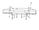
まず、本発明の実施形態に係る保護膜形成装置1を図面に基づいて説明する。図1は、実施形態の保護膜形成装置1の構成例を模式的に一部断面で示す側面図である。図2は、図1に示された保護膜形成装置1の加工対象の被加工物100の斜視図である。図3は、図1に示す霧化ユニット30の振動面33の構成例を一部断面で示す側面図である。図4は、図1に示すエアカーテン形成ユニット50の要部の構成例を一部断面で示す斜視図である。
[Embodiment]
First, a protective
図1に示すように、実施形態の保護膜形成装置1は、保持テーブル10と、塗布ユニット20と、洗浄機構60と、液状樹脂滴下ユニット70(後述の図6参照)と、を備える。なお、本明細書に添付した図面では、説明のために塗布ユニット20を保護膜形成装置1の他の構成要素より誇張して相対的に大きく描写しているが、実際には、保持テーブル10の上方に位置する作動位置と、保持テーブル10の上方から離間した退避位置との間で移動可能な大きさである。
As shown in FIG. 1, the protective
保護膜形成装置1は、保持テーブル10に保持された被加工物100に対して、塗布ユニット20から霧化した液状樹脂41を塗布させることにより、被加工物100に保護膜120(図8参照)を形成する装置である。被加工物100は、シリコン(Si)、サファイア(Al2O3)、ガリウムヒ素(GaAs)または炭化ケイ素(SiC)等を基板101とする円板状の半導体ウェーハ、光デバイスウェーハ等のウェーハである。
The protective
図2に示すように、被加工物100は、基板101の表面102に格子状に設定される複数の分割予定ライン103と、分割予定ライン103によって区画された領域に形成されたデバイス104と、を有する。デバイス104は、例えば、IC(Integrated Circuit)、あるいはLSI(Large Scale Integration)等の集積回路、CCD(Charge Coupled Device)、あるいはCMOS(Complementary Metal Oxide Semiconductor)等のイメージセンサ等である。デバイス104が形成された表面102と反対側に位置する被加工物100の面を裏面105とする。
2, the
実施形態において、被加工物100は、デバイス104の表面に複数の電極バンプ106を搭載して、表面102に凹凸が形成されている。電極バンプ106は、200μm程度の高さを有し、デバイス104の表面から突出している。デバイス104は、表面102に電極バンプ106が搭載されていることで、凹凸の構造物を備えている。被加工物100は、分割予定ライン103に沿って個々のデバイス104に分割されて、チップ107に個片化される。なお、チップ107は、図2において、正方形状であるが、長方形状であってもよい。また、被加工物100は、実施形態では、デバイス104の表面から突出した電極バンプ106を搭載することで、表面102に凹凸が形成されているが、本発明では、電極バンプ106の搭載に限定されずに、表面102側に凹凸が形成されていればよい。
In the embodiment, the
実施形態において、被加工物100は、環状のフレーム110に貼着されかつ被加工物100の外径よりも大径な貼着テープ111が裏面105に貼着されて、フレーム110の開口内に支持される。
In this embodiment, the
保持テーブル10は、被加工物100を保持面11で保持する。保持面11は、ポーラスセラミック等から形成された円板形状である。保持面11は、実施形態において、水平方向と平行な平面である。保持面11は、例えば、真空吸引経路を介して真空吸引源と連通している。保持テーブル10は、保持面11上に載置された被加工物100を吸引保持する。保持テーブル10の周囲には、被加工物100を支持する環状のフレーム110を挟持するクランプ部材12が複数配置されている。保持テーブル10は、保持テーブル10を下方から支持する回転ユニット13によって、垂直な軸心回りに回動可能である。
The holding table 10 holds the
塗布ユニット20は、保持テーブル10に保持された被加工物100の上面(表面102)に、霧化した液状樹脂41を塗布して保護膜120(第二の保護膜122、図8参照)を形成するユニットである。塗布ユニット20は、不図示の移動ユニットによって、保持テーブル10の上方に位置する作動位置と、保持テーブル10の保持面11の上方から離間した退避位置との間で移動可能である。塗布ユニット20は、霧化ユニット30と、液状樹脂供給ユニット40と、エアカーテン形成ユニット50と、を備える。
The
霧化ユニット30は、後述の液状樹脂供給ユニット40から供給される液状樹脂41を霧化するユニットである。霧化ユニット30は、超音波振動子31を含む。超音波振動子31は、所定の振幅および周波数で振動することによって超音波を発生させる。超音波振動子31は、実施形態において、例えば、振幅が30μm、出力が20W、周波数が52kHzで振動する。超音波振動子31は、例えば、荷電されることにより伸縮する圧電素子を含む。
The
超音波振動子31は、振動を増幅するホーン32を備える。ホーン32には、後述の液状樹脂供給ユニット40から液状樹脂41が供給される。ホーン32は、保持テーブル10に保持された被加工物100に対面する振動面33を有する。振動面33と被加工物100の表面102との距離は、実施形態において、10mm以上20mm以下である。
The
図3に示すように、超音波振動子31は、更に、振動板34を備える。振動板34は、ねじ35等によって、ホーン32の振動面33側に固定される。すなわち、振動板34は、ホーン32と共に振動する。振動板34の厚みは、実施形態において、100μm未満である。振動板34は、ホーン32の振動面33との間に微小な間隙36を有するように配置される。
As shown in FIG. 3, the
間隙36の、振動面33と振動板34との間の距離(垂直方向距離)は、実施形態において、100μm未満である。間隙36には、後述の液状樹脂供給ユニット40から液状樹脂41が供給される。霧化ユニット30は、液状樹脂供給ユニット40から液状樹脂41を供給された状態で、超音波振動子31を振動させることによって、液状樹脂41を霧化することができる。
In the embodiment, the distance (vertical distance) of the
図1に示すように、超音波振動子31は、更に、放熱部37を備える。放熱部37は、振動によって加熱した超音波振動子31から熱を放熱する。放熱部37は、例えば、ヒートシンクを含む。ヒートシンクは、例えば、水冷によって冷却可能である。
As shown in FIG. 1, the
液状樹脂供給ユニット40は、液状樹脂41を霧化ユニット30に供給するユニットである。液状樹脂供給ユニット40は、実施形態において、ホーン32に対して液状樹脂41を供給する液状樹脂供給ノズル42を備える。液状樹脂供給ノズル42は、間隙36(図3参照)に対して液状樹脂41を供給することが好ましい。液状樹脂供給ノズル42の供給口43は、実施形態において、後述のエアカーテン形成ユニット50の気体供給ノズル52より内側に位置する。液状樹脂供給ユニット40は、実施形態において、0.2mL/min以上1mL/min以下の供給量で、液状樹脂41を供給する。また、液状樹脂41の粘度は、実施形態において、52cPである。液状樹脂41の粘度は、実施形態に限定されず、霧化ユニット30によって霧化可能であれば適宜変更して構わない。
The liquid
エアカーテン形成ユニット50は、被加工物100に向かって気体51を供給し、ホーン32と被加工物100との間の霧化した液状樹脂41が被加工物100に塗布されるまでの領域の側方を囲うエアカーテン54を形成するユニットである。エアカーテン形成ユニット50は、気体供給ノズル52を備える。
The air
気体供給ノズル52は、被加工物100に向かって気体51を噴出する。気体供給ノズル52は、超音波振動子31を囲むように配設される。図4に示すように、気体供給ノズル52は、実施形態において、噴出口53が下方側に開口するスリット形状、かつ超音波振動子31(図1参照)の側方を囲む円環状に配設される。エアカーテン形成ユニット50は、気体供給ノズル52の噴出口53から被加工物100に向かって噴出した気体51の流れによって、霧化した液状樹脂41を囲むエアカーテン54を形成する。実施形態では噴出口53が円環状に配置されるため、エアカーテン54は、概ね円筒状に形成される。
The
実施形態において、エアカーテン54を形成する気体51の流れは、霧化した液状樹脂41の被加工物100に向かう方向に沿っている。ここで、「沿っている」とは、平行であること、及び互いのなす角度が微小な角度であることを含む。また、実施形態において、エアカーテン54を形成する気体51の流れの向きは、霧化した液状樹脂41の被加工物に向かう方向と同じ向きである。
In the embodiment, the flow of
気体供給ノズル52から供給される気体51は、25℃以上80℃以下の温風またはドライエア、あるいは温風およびドライエアの混合気体であることが好ましい。図1に示すように、エアカーテン形成ユニット50は、実施形態において、更に、熱源55を備える。熱源55は、気体供給ノズル52から供給される気体51を加熱する。これにより、被加工物100の表面102に塗布した液状樹脂41の乾燥を促進させることができる。エアカーテン形成ユニット50は、実施形態において、70mL/minの流量で、気体51を供給する。
The
保護膜形成装置1は、超音波振動子31を振動させた状態で、液状樹脂供給ノズル42からホーン32に液状樹脂41を供給することによって、霧化した液状樹脂41を被加工物100に塗布することができる。この際、気体供給ノズル52から噴出した気体51で形成したエアカーテン54が霧化した液状樹脂41を囲むことによって、外乱の影響を抑制された状態で被加工物100に霧化した液状樹脂41を塗布することが可能である。
The protective
保護膜形成装置1は、塗布ユニット20と保持テーブル10とを相対的に移動させることによって、被加工物100の表面102の前面に液状樹脂41を塗布し、被加工物100の表面102を覆う保護膜120(第二の保護膜122、図8参照)を形成することができる。保護膜形成装置1は、例えば、塗布ユニット20と保持テーブル10とを相対的に螺旋状に移動させる。また、保護膜形成装置1は、被加工物100の表面102の凹凸(電極バンプ106)が覆われるまで、繰り返し、例えば5パス、塗布を実施する。
The protective
洗浄機構60は、ホーン32の先端に固着した液状樹脂41を除去するための機構である。図1に示すように、洗浄機構60は、例えば、洗浄液61をホーン32の振動面33に供給する洗浄液供給ノズル62や、振動面33を浸すことができる洗浄液61で満たされた液槽64等を含む。洗浄液供給ノズル62の供給口63は、実施形態において、エアカーテン形成ユニット50の気体供給ノズル52より内側に位置する。
The
後述の図6に示すように、液状樹脂滴下ユニット70は、保持テーブル10に保持された被加工物100の上面(表面102)に所定量の液状樹脂71を滴下するユニットである。液状樹脂滴下ユニット70は、液状樹脂滴下ノズル72を備える。液状樹脂71は、塗布ユニット20の液状樹脂供給ユニット40が供給する液状樹脂41と同様のものである。
As shown in FIG. 6, which will be described later, the liquid
液状樹脂滴下ノズル72は、保持テーブル10に保持された被加工物100の上面(表面102)に所定量の液状樹脂71を滴下する。液状樹脂滴下ノズル72は、不図示の移動ユニットによって、供給口73が保持テーブル10に保持された被加工物100に向けられる滴下位置と、保持テーブル10の保持面11の上方から離間した退避位置との間で移動可能である。
The liquid
保護膜形成装置1は、液状樹脂滴下ユニット70によって被加工物100の表面102に所定量の液状樹脂71を滴下させるとともに、保持テーブル10を回転させることによって、液状樹脂71を拡散させ、被加工物100の表面102を覆う第一の保護膜121(図7参照)を形成することができる。
The protective
次に、本発明の実施形態に係る保護膜形成方法を図面に基づいて説明する。図5は、実施形態の保護膜形成方法の流れを示すフローチャート図である。実施形態の保護膜形成方法は、保持ステップ201と、第一の保護膜形成ステップ202と、第二の保護膜形成ステップ203と、を含む。
Next, a protective film forming method according to an embodiment of the present invention will be described with reference to the drawings. FIG. 5 is a flow chart showing the flow of the protective film forming method according to the embodiment. The protective film forming method according to the embodiment includes a holding
(保持ステップ201)
保持ステップ201は、図1に示す保持テーブル10に被加工物100を保持するステップである。保持ステップ201では、まず、被加工物100の裏面105側を、環状のフレーム110に貼着されかつ被加工物100の外径よりも大径な貼着テープ111に貼着することによって、被加工物100をフレーム110の開口内に支持する。次に、貼着テープ111を介して被加工物100の裏面105側を保持テーブル10の保持面11に吸引保持するとともに、クランプ部材12でフレーム110をクランプする。
(Retention Step 201)
The holding
(第一の保護膜形成ステップ202)
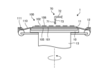
図6は、図5に示す第一の保護膜形成ステップ202の一例を模式的に一部断面で示す側面図である。図7は、図5に示す第一の保護膜形成ステップ202の後の一状態の被加工物100の要部を示す断面図である。第一の保護膜形成ステップ202は、被加工物100の上面(表面102)を覆う第一の保護膜121を形成するステップである。
(First protective film forming step 202)
Fig. 6 is a side view, partially in cross section, showing a schematic example of the first protective
第一の保護膜形成ステップ202では、まず、不図示の移動ユニットによって、液状樹脂滴下ユニット70を供給口73が保持テーブル10に保持された被加工物100に向けられる滴下位置に移動させる。次に、液状樹脂滴下ノズル72から、保持テーブル10に保持された被加工物100の上面(表面102)に所定量の液状樹脂71を滴下するとともに、保持テーブル10を垂直な軸心回りに回転させる。これにより、被加工物100の表面102に滴下した液状樹脂71を、遠心力により被加工物100の外周方向へ拡散させる。
In the first protective
図7に示すように、拡散した液状樹脂71は、第一の保護膜121として、被加工物100の表面102を覆う。第一の保護膜121は、被加工物100の表面102に搭載された複数の電極バンプ106によって形成される凹凸の凸部分を露出している。
As shown in FIG. 7, the diffused liquid resin 71 covers the
(第二の保護膜形成ステップ203)
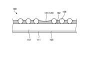
図8は、図5に示す第二の保護膜形成ステップ203の後の一状態の被加工物100の要部を示す断面図である。第二の保護膜形成ステップ203は、被加工物100の上面(表面102)の全面を覆う第二の保護膜122を形成するステップである。第二の保護膜形成ステップ203は、第一の保護膜形成ステップ202の後に実施される。
(Second protective film forming step 203)
8 is a cross-sectional view showing a main part of the
第二の保護膜形成ステップ203では、まず、不図示の移動ユニットによって、塗布ユニット20を保持テーブル10の上方に位置する作動位置に移動させる(図1参照)。次に、エアカーテン形成ユニット50によって、被加工物100に向かって気体供給ノズル52から気体51を供給する。これにより、ホーン32と被加工物100との間の領域の側方を囲うエアカーテン54を形成する。次に、霧化ユニット30の超音波振動子31を振動させることによって、超音波を発生させる。超音波振動子31の振動は、ホーン32に伝達され増幅される。
In the second protective
第二の保護膜形成ステップ203では、エアカーテン54を形成し、超音波振動子31を振動させた状態で、液状樹脂供給ユニット40によって、液状樹脂供給ノズル42からホーン32に液状樹脂41を供給する。より詳しくは、液状樹脂41を、ホーン32の振動面33と振動板34との間の間隙36に供給する。超音波振動子31の振動により発生した超音波によって、液状樹脂41が霧化される。
In the second protective
図1に示すように、液状樹脂供給ノズル42は、気体供給ノズル52より内側に設けられる。すなわち、霧化した液状樹脂41は、エアカーテン54に囲まれた領域を下降して、被加工物100の上面(表面102)に塗布される。すなわち、第二の保護膜形成ステップ203では、液状樹脂41を霧化するとともに、霧化した液状樹脂41を囲むエアカーテン54を形成した状態で、保持テーブル10に保持された被加工物100の表面102に対して霧化した液状樹脂41を供給する。
As shown in FIG. 1, the liquid
図8に示すように、霧化して被加工物100の表面102に供給された液状樹脂41は、第二の保護膜122として、被加工物100の表面102を電極バンプ106ごと覆う。塗布ユニット20は、エアカーテン54が霧化した液状樹脂41を囲むことによって、外乱の影響を抑制した状態で被加工物100に霧化した液状樹脂41を塗布することが可能であるため、電極バンプ106を覆う第二の保護膜122の厚みを均一にすることができる。
As shown in FIG. 8, the
以上説明したように、実施形態の保護膜形成装置1および保護膜形成方法は、霧化した液状樹脂41が被加工物100の表面102に塗布されるまで領域を囲うエアカーテン54を形成する。例えば、霧化した液状樹脂41は、塗布ユニット20が被加工物100の上部をスキャンする動作や、保持テーブル10が回転または平行移動する際に発生する僅かな気流の流れでも揺らぎが発生するため、被加工物100の所望の領域に対して塗布することが難しい。実施形態の保護膜形成装置1では、エアカーテン54によって、霧化した液状樹脂41に対する外乱の影響を抑制しているため、被加工物100に対して保護膜120を均一に塗布することができる。
As described above, the protective
なお、本発明は、上記実施形態に限定されるものではない。すなわち、本発明の骨子を逸脱しない範囲で種々変形して実施することができる。例えば、気体供給ノズル52は、実施形態では噴出口53が下方側に円環状に開口するスリット形状であるが、本発明では円環状に複数配置される孔形状でもよい。
The present invention is not limited to the above embodiment. In other words, various modifications can be made without departing from the gist of the present invention. For example, in the embodiment, the
また、保護膜形成装置1は、塗布した液状樹脂41の乾燥を促進するために、保持テーブル10を加温する機構や、ハロゲンライトを被加工物100の上面(表面102)に照射する機構を設けてもよい。また、供給する液状樹脂41にエタノールを混合して、乾燥性を向上させてもよい。
The protective
また、霧化ユニット30のホーン32の振動面33は、実施形態の構成に限定されず、本発明では、例えば、図9および図10に示すような構成でもよい。
Furthermore, the
図9は、第1変形例の霧化ユニット30-1の振動面33の構成例を一部断面で示す側面図である。第1変形例の霧化ユニット30-1は、実施形態の霧化ユニット30と比較して、振動板34-1の構成と、ねじ35-1をねじ止めする方向と、が異なる。すなわち、実施形態の振動板34が、ホーン32の下面である振動面33および下端近傍の側面を覆う蓋形状であり、周面部分をねじ35によって側方からねじ止めされる構成であるのに対し、第1変形例の振動板34-1は、平板形状であり、スペーサ38-1を介して下方からねじ35-1にねじ止めされる構成である。第1変形例の振動板34-1と振動面33との間の間隙36-1は、スペーサ38-1によって形成される。
Figure 9 is a side view showing a partial cross section of an example of the configuration of the
図10は、第2変形例の霧化ユニット30-2の振動面33の構成例を一部断面で示す側面図である。第2変形例の霧化ユニット30-2は、実施形態の霧化ユニット30と比較して、ホーン32と、振動板34-2とが、一体化して形成される点が異なる。すなわち、実施形態の振動板34が、ホーン32と別体で設けられてねじ35によってホーン32に固定される構成であるのに対し、第2変形例の振動板34-2は、連結部39-2を介してホーン32と一体で設けられる。連結部39-2は、例えば、ホーン32の振動面33の周縁から下方に延設され、平板形状の振動板34-2の上面側に連結する。第2変形例の振動板34-2と振動面33との間の間隙36-2は、スペーサとしての連結部39-2によって形成される。
Figure 10 is a side view showing a partial cross section of an example of the configuration of the
1 保護膜形成装置
10 保持テーブル
20 塗布ユニット
30、30-1、30-2 霧化ユニット
31 超音波振動子
32 ホーン
33 振動面
34、34-1、34-2 振動板
36、36-1、36-2 間隙
40 液状樹脂供給ユニット
41 液状樹脂
42 液状樹脂供給ノズル
43 供給口
50 エアカーテン形成ユニット
51 気体
52 気体供給ノズル
53 噴出口
54 エアカーテン
55 熱源
60 洗浄機構
70 液状樹脂滴下ユニット
71 液状樹脂
72 液状樹脂滴下ノズル
73 供給口
100 被加工物
102 表面(上面)
120 保護膜
121 第一の保護膜
122 第二の保護膜
LIST OF
120
Claims (7)
被加工物を保持する保持テーブルと、
該保持テーブルに保持された被加工物の上面に液状樹脂を塗布して保護膜を形成する塗布ユニットと、
を備え、
該塗布ユニットは、
該保持テーブルに保持された被加工物に対面する振動面を有するホーンを備えた超音波振動子と、
該ホーンに対して液状樹脂を供給する液状樹脂供給ノズルと、
該超音波振動子を囲むように配設され、該被加工物に向かって気体を噴出する噴出口を有する気体供給ノズルと、
を含み、
該超音波振動子を振動させた状態で該液状樹脂供給ノズルから該ホーンに液状樹脂を供給することによって該液状樹脂を霧化可能であるとともに、該気体供給ノズルの噴出口から噴出した気体の流れによって霧化した該液状樹脂を囲むエアカーテンを形成可能であり、
該超音波振動子は、該ホーンの該振動面との間に微小な間隙を有するように配置された振動板を備えることを特徴とする、
保護膜形成装置。 A protective film forming device for forming a protective film on a workpiece,
A holding table for holding the workpiece;
a coating unit for coating a liquid resin on an upper surface of the workpiece held on the holding table to form a protective film;
Equipped with
The application unit comprises:
an ultrasonic transducer including a horn having a vibration surface facing the workpiece held on the holding table;
a liquid resin supply nozzle that supplies liquid resin to the horn;
a gas supply nozzle disposed so as to surround the ultrasonic transducer and having an outlet for ejecting gas toward the workpiece;
Including,
The liquid resin can be atomized by supplying the liquid resin from the liquid resin supply nozzle to the horn while the ultrasonic vibrator is vibrated, and an air curtain can be formed surrounding the atomized liquid resin by a flow of gas ejected from the outlet of the gas supply nozzle ,
The ultrasonic transducer is characterized in that it includes a vibration plate arranged so as to have a minute gap between the vibration surface of the horn and the vibration plate .
Protective film forming device.
請求項1に記載の保護膜形成装置。 The horn and the diaphragm are integrally formed.
The protective film forming apparatus according to claim 1 .
請求項1または2に記載の保護膜形成装置。 The liquid resin supply nozzle supplies liquid resin to the gap.
The protective film forming apparatus according to claim 1 .
請求項1乃至3のいずれか1項に記載の保護膜形成装置。 The present invention further comprises a cleaning mechanism for removing the liquid resin adhered to the horn.
The protective film forming apparatus according to claim 1 .
請求項1乃至4のいずれか1項に記載の保護膜形成装置。 The gas supplied from the gas supply nozzle is dry air.
The protective film forming apparatus according to claim 1 .
請求項1乃至5のいずれか1項に記載の保護膜形成装置。 The gas supply system further comprises a heat source for heating the gas supplied from the gas supply nozzle.
The protective film forming apparatus according to claim 1 .
請求項1乃至6のいずれか1項に記載の保護膜形成装置。 The present invention is characterized in that the liquid resin further includes a liquid resin dripping nozzle for dripping liquid resin onto an upper surface of the workpiece held on the holding table.
The protective film forming apparatus according to claim 1 .
Priority Applications (2)
| Application Number | Priority Date | Filing Date | Title |
|---|---|---|---|
| JP2021058037A JP7682002B2 (en) | 2021-03-30 | 2021-03-30 | Protective film forming device |
| JP2025021398A JP7789967B2 (en) | 2021-03-30 | 2025-02-13 | Protective film formation method |
Applications Claiming Priority (1)
| Application Number | Priority Date | Filing Date | Title |
|---|---|---|---|
| JP2021058037A JP7682002B2 (en) | 2021-03-30 | 2021-03-30 | Protective film forming device |
Related Child Applications (1)
| Application Number | Title | Priority Date | Filing Date |
|---|---|---|---|
| JP2025021398A Division JP7789967B2 (en) | 2021-03-30 | 2025-02-13 | Protective film formation method |
Publications (2)
| Publication Number | Publication Date |
|---|---|
| JP2022154819A JP2022154819A (en) | 2022-10-13 |
| JP7682002B2 true JP7682002B2 (en) | 2025-05-23 |
Family
ID=83557137
Family Applications (2)
| Application Number | Title | Priority Date | Filing Date |
|---|---|---|---|
| JP2021058037A Active JP7682002B2 (en) | 2021-03-30 | 2021-03-30 | Protective film forming device |
| JP2025021398A Active JP7789967B2 (en) | 2021-03-30 | 2025-02-13 | Protective film formation method |
Family Applications After (1)
| Application Number | Title | Priority Date | Filing Date |
|---|---|---|---|
| JP2025021398A Active JP7789967B2 (en) | 2021-03-30 | 2025-02-13 | Protective film formation method |
Country Status (1)
| Country | Link |
|---|---|
| JP (2) | JP7682002B2 (en) |
Citations (4)
| Publication number | Priority date | Publication date | Assignee | Title |
|---|---|---|---|---|
| WO2009096346A1 (en) | 2008-01-31 | 2009-08-06 | Mitsubishi Electric Corporation | Ultrasonic wave generating device, and apparatus having the device |
| JP2010125351A (en) | 2008-11-25 | 2010-06-10 | Disco Abrasive Syst Ltd | Method of applying protective film, and apparatus of applying protective film |
| WO2020162130A1 (en) | 2019-02-04 | 2020-08-13 | 富士フイルム株式会社 | Method for forming organic semiconductor film |
| WO2021019930A1 (en) | 2019-07-26 | 2021-02-04 | 富士フイルム株式会社 | Spray device and spray coating method |
Family Cites Families (6)
| Publication number | Priority date | Publication date | Assignee | Title |
|---|---|---|---|---|
| JPH03147853A (en) * | 1989-11-02 | 1991-06-24 | Seiko Epson Corp | printing device |
| JPH04265172A (en) * | 1991-02-20 | 1992-09-21 | Hiroshi Saito | Ultrasonic electrifying injection device |
| JP3084339B2 (en) * | 1993-05-31 | 2000-09-04 | 東京エレクトロン株式会社 | Coating method and apparatus |
| JP2004016916A (en) * | 2002-06-14 | 2004-01-22 | Seiko Epson Corp | Coating method, coating device, and electronic device |
| JP2010087198A (en) * | 2008-09-30 | 2010-04-15 | M Setek Co Ltd | Resist coating device, and coating method therein |
| JP2017041574A (en) * | 2015-08-21 | 2017-02-23 | 株式会社ディスコ | Wafer processing method |
-
2021
- 2021-03-30 JP JP2021058037A patent/JP7682002B2/en active Active
-
2025
- 2025-02-13 JP JP2025021398A patent/JP7789967B2/en active Active
Patent Citations (4)
| Publication number | Priority date | Publication date | Assignee | Title |
|---|---|---|---|---|
| WO2009096346A1 (en) | 2008-01-31 | 2009-08-06 | Mitsubishi Electric Corporation | Ultrasonic wave generating device, and apparatus having the device |
| JP2010125351A (en) | 2008-11-25 | 2010-06-10 | Disco Abrasive Syst Ltd | Method of applying protective film, and apparatus of applying protective film |
| WO2020162130A1 (en) | 2019-02-04 | 2020-08-13 | 富士フイルム株式会社 | Method for forming organic semiconductor film |
| WO2021019930A1 (en) | 2019-07-26 | 2021-02-04 | 富士フイルム株式会社 | Spray device and spray coating method |
Also Published As
| Publication number | Publication date |
|---|---|
| JP2022154819A (en) | 2022-10-13 |
| JP7789967B2 (en) | 2025-12-22 |
| JP2025067969A (en) | 2025-04-24 |
Similar Documents
| Publication | Publication Date | Title |
|---|---|---|
| US20100129546A1 (en) | Protective film forming method and apparatus | |
| CN103962274B (en) | Resin cladding system | |
| JP5881464B2 (en) | Wafer laser processing method | |
| JP2010207723A (en) | Resin film forming apparatus | |
| JP2010089109A (en) | Method and apparatus for laser machining | |
| JP7295621B2 (en) | Wafer cutting method and wafer division method | |
| US7799700B2 (en) | Method for applying resin film to face of semiconductor wafer | |
| WO2020054424A1 (en) | Application-film forming method and application-film forming device | |
| CN102059197B (en) | Spray coating system and method | |
| KR20200019086A (en) | Carrier plate removing method | |
| JP7682002B2 (en) | Protective film forming device | |
| JP6101460B2 (en) | Wafer processing method | |
| JP2016187004A (en) | Wafer processing method | |
| JP7737853B2 (en) | Liquid resin application device | |
| US20250140622A1 (en) | Method of fixing protective member | |
| JP2023109596A (en) | Workpiece processing method | |
| JP2022033584A (en) | Cleaning device for plate-shaped objects and cleaning method | |
| CN107579042A (en) | The processing method of chip | |
| JP2024179968A (en) | Liquid resin application device | |
| JP2024117423A (en) | Liquid resin application device | |
| JP6866038B2 (en) | Manufacturing method of packaged device | |
| JP7483413B2 (en) | Protective Film Forming Equipment | |
| TWI866063B (en) | Apparatus for cleansing wafer | |
| JP2008523598A (en) | Apparatus and method for drying disk-shaped substrate | |
| JP7680266B2 (en) | Liquid resin application nozzle |
Legal Events
| Date | Code | Title | Description |
|---|---|---|---|
| A621 | Written request for application examination |
Free format text: JAPANESE INTERMEDIATE CODE: A621 Effective date: 20240219 |
|
| A977 | Report on retrieval |
Free format text: JAPANESE INTERMEDIATE CODE: A971007 Effective date: 20241129 |
|
| A131 | Notification of reasons for refusal |
Free format text: JAPANESE INTERMEDIATE CODE: A131 Effective date: 20241217 |
|
| A521 | Request for written amendment filed |
Free format text: JAPANESE INTERMEDIATE CODE: A523 Effective date: 20250213 |
|
| TRDD | Decision of grant or rejection written | ||
| A01 | Written decision to grant a patent or to grant a registration (utility model) |
Free format text: JAPANESE INTERMEDIATE CODE: A01 Effective date: 20250422 |
|
| A61 | First payment of annual fees (during grant procedure) |
Free format text: JAPANESE INTERMEDIATE CODE: A61 Effective date: 20250513 |
|
| R150 | Certificate of patent or registration of utility model |
Ref document number: 7682002 Country of ref document: JP Free format text: JAPANESE INTERMEDIATE CODE: R150 |