JP7653045B2 - Gaming Machines - Google Patents
Gaming Machines Download PDFInfo
- Publication number
- JP7653045B2 JP7653045B2 JP2024071134A JP2024071134A JP7653045B2 JP 7653045 B2 JP7653045 B2 JP 7653045B2 JP 2024071134 A JP2024071134 A JP 2024071134A JP 2024071134 A JP2024071134 A JP 2024071134A JP 7653045 B2 JP7653045 B2 JP 7653045B2
- Authority
- JP
- Japan
- Prior art keywords
- game
- pattern
- special
- state
- display
- Prior art date
- Legal status (The legal status is an assumption and is not a legal conclusion. Google has not performed a legal analysis and makes no representation as to the accuracy of the status listed.)
- Active
Links
- 238000001514 detection method Methods 0.000 claims description 274
- 238000003825 pressing Methods 0.000 claims description 49
- 230000000994 depressogenic effect Effects 0.000 claims description 4
- 238000000034 method Methods 0.000 description 1000
- 230000008569 process Effects 0.000 description 930
- 230000000694 effects Effects 0.000 description 354
- 238000012545 processing Methods 0.000 description 342
- 230000008859 change Effects 0.000 description 235
- 230000007704 transition Effects 0.000 description 188
- 230000006870 function Effects 0.000 description 146
- 238000003780 insertion Methods 0.000 description 89
- 230000037431 insertion Effects 0.000 description 89
- 238000010586 diagram Methods 0.000 description 87
- 238000006073 displacement reaction Methods 0.000 description 84
- 230000002349 favourable effect Effects 0.000 description 82
- 230000007257 malfunction Effects 0.000 description 80
- 230000002238 attenuated effect Effects 0.000 description 54
- 238000012544 monitoring process Methods 0.000 description 45
- 230000005540 biological transmission Effects 0.000 description 38
- 238000012790 confirmation Methods 0.000 description 37
- 238000013461 design Methods 0.000 description 33
- 238000003860 storage Methods 0.000 description 31
- 238000009987 spinning Methods 0.000 description 30
- 230000006378 damage Effects 0.000 description 29
- 239000000758 substrate Substances 0.000 description 27
- 238000011084 recovery Methods 0.000 description 25
- 230000007246 mechanism Effects 0.000 description 22
- 230000005856 abnormality Effects 0.000 description 21
- 230000009471 action Effects 0.000 description 21
- 230000000630 rising effect Effects 0.000 description 19
- 238000005516 engineering process Methods 0.000 description 18
- 230000017525 heat dissipation Effects 0.000 description 18
- 238000007726 management method Methods 0.000 description 18
- 244000145845 chattering Species 0.000 description 17
- 239000004973 liquid crystal related substance Substances 0.000 description 16
- 230000001133 acceleration Effects 0.000 description 15
- 230000002159 abnormal effect Effects 0.000 description 14
- 239000011521 glass Substances 0.000 description 14
- 230000001681 protective effect Effects 0.000 description 14
- 238000012360 testing method Methods 0.000 description 14
- 239000000463 material Substances 0.000 description 12
- 238000004458 analytical method Methods 0.000 description 11
- 238000004891 communication Methods 0.000 description 11
- 230000001186 cumulative effect Effects 0.000 description 11
- 230000004044 response Effects 0.000 description 11
- 238000004364 calculation method Methods 0.000 description 10
- 238000010304 firing Methods 0.000 description 10
- 229910052751 metal Inorganic materials 0.000 description 10
- 239000002184 metal Substances 0.000 description 10
- 239000004033 plastic Substances 0.000 description 10
- 230000009467 reduction Effects 0.000 description 9
- 230000002829 reductive effect Effects 0.000 description 9
- BQCADISMDOOEFD-UHFFFAOYSA-N Silver Chemical compound [Ag] BQCADISMDOOEFD-UHFFFAOYSA-N 0.000 description 8
- 229920005989 resin Polymers 0.000 description 8
- 239000011347 resin Substances 0.000 description 8
- 229910052709 silver Inorganic materials 0.000 description 8
- 239000004332 silver Substances 0.000 description 8
- 230000014759 maintenance of location Effects 0.000 description 7
- 238000002360 preparation method Methods 0.000 description 7
- 230000001960 triggered effect Effects 0.000 description 7
- 230000008901 benefit Effects 0.000 description 6
- 230000000903 blocking effect Effects 0.000 description 6
- 238000005034 decoration Methods 0.000 description 6
- 238000011161 development Methods 0.000 description 6
- 230000003213 activating effect Effects 0.000 description 5
- 230000007547 defect Effects 0.000 description 5
- 230000005284 excitation Effects 0.000 description 5
- 210000003128 head Anatomy 0.000 description 5
- 230000000717 retained effect Effects 0.000 description 5
- 230000002441 reversible effect Effects 0.000 description 5
- 238000013016 damping Methods 0.000 description 4
- 230000003247 decreasing effect Effects 0.000 description 4
- 230000000670 limiting effect Effects 0.000 description 4
- 238000005259 measurement Methods 0.000 description 4
- 230000004913 activation Effects 0.000 description 3
- 230000004397 blinking Effects 0.000 description 3
- 238000007599 discharging Methods 0.000 description 3
- 238000009434 installation Methods 0.000 description 3
- 230000001678 irradiating effect Effects 0.000 description 3
- 230000008685 targeting Effects 0.000 description 3
- 239000002023 wood Substances 0.000 description 3
- 241000219109 Citrullus Species 0.000 description 2
- 235000012828 Citrullus lanatus var citroides Nutrition 0.000 description 2
- 208000001613 Gambling Diseases 0.000 description 2
- 241001272720 Medialuna californiensis Species 0.000 description 2
- 235000019504 cigarettes Nutrition 0.000 description 2
- 239000013078 crystal Substances 0.000 description 2
- 238000013500 data storage Methods 0.000 description 2
- 230000002427 irreversible effect Effects 0.000 description 2
- 238000004519 manufacturing process Methods 0.000 description 2
- 238000011056 performance test Methods 0.000 description 2
- 230000002093 peripheral effect Effects 0.000 description 2
- 238000007747 plating Methods 0.000 description 2
- 230000002250 progressing effect Effects 0.000 description 2
- 238000010187 selection method Methods 0.000 description 2
- 206010000117 Abnormal behaviour Diseases 0.000 description 1
- 241000167854 Bourreria succulenta Species 0.000 description 1
- VYZAMTAEIAYCRO-UHFFFAOYSA-N Chromium Chemical compound [Cr] VYZAMTAEIAYCRO-UHFFFAOYSA-N 0.000 description 1
- 206010012335 Dependence Diseases 0.000 description 1
- 244000208734 Pisonia aculeata Species 0.000 description 1
- 229930182556 Polyacetal Natural products 0.000 description 1
- 241000287531 Psittacidae Species 0.000 description 1
- 206010047571 Visual impairment Diseases 0.000 description 1
- 230000006399 behavior Effects 0.000 description 1
- 238000005452 bending Methods 0.000 description 1
- 235000019693 cherries Nutrition 0.000 description 1
- 238000001816 cooling Methods 0.000 description 1
- 238000002788 crimping Methods 0.000 description 1
- 238000005520 cutting process Methods 0.000 description 1
- 230000001934 delay Effects 0.000 description 1
- 230000003111 delayed effect Effects 0.000 description 1
- 230000001419 dependent effect Effects 0.000 description 1
- 230000000881 depressing effect Effects 0.000 description 1
- 230000006866 deterioration Effects 0.000 description 1
- 239000003822 epoxy resin Substances 0.000 description 1
- 238000004880 explosion Methods 0.000 description 1
- 238000000605 extraction Methods 0.000 description 1
- 210000000887 face Anatomy 0.000 description 1
- 238000001914 filtration Methods 0.000 description 1
- 238000005286 illumination Methods 0.000 description 1
- 230000006872 improvement Effects 0.000 description 1
- 238000007562 laser obscuration time method Methods 0.000 description 1
- 230000007774 longterm Effects 0.000 description 1
- 230000004048 modification Effects 0.000 description 1
- 238000012986 modification Methods 0.000 description 1
- 230000008450 motivation Effects 0.000 description 1
- 230000001151 other effect Effects 0.000 description 1
- 230000000737 periodic effect Effects 0.000 description 1
- 229920000647 polyepoxide Polymers 0.000 description 1
- 229920006324 polyoxymethylene Polymers 0.000 description 1
- 230000002035 prolonged effect Effects 0.000 description 1
- 238000007789 sealing Methods 0.000 description 1
- 238000004904 shortening Methods 0.000 description 1
- 239000007787 solid Substances 0.000 description 1
- 230000001360 synchronised effect Effects 0.000 description 1
- 229920003002 synthetic resin Polymers 0.000 description 1
- 239000000057 synthetic resin Substances 0.000 description 1
- 239000010409 thin film Substances 0.000 description 1
- 238000011144 upstream manufacturing Methods 0.000 description 1
- 230000000007 visual effect Effects 0.000 description 1
Images


Classifications
-
- Y—GENERAL TAGGING OF NEW TECHNOLOGICAL DEVELOPMENTS; GENERAL TAGGING OF CROSS-SECTIONAL TECHNOLOGIES SPANNING OVER SEVERAL SECTIONS OF THE IPC; TECHNICAL SUBJECTS COVERED BY FORMER USPC CROSS-REFERENCE ART COLLECTIONS [XRACs] AND DIGESTS
- Y02—TECHNOLOGIES OR APPLICATIONS FOR MITIGATION OR ADAPTATION AGAINST CLIMATE CHANGE
- Y02E—REDUCTION OF GREENHOUSE GAS [GHG] EMISSIONS, RELATED TO ENERGY GENERATION, TRANSMISSION OR DISTRIBUTION
- Y02E60/00—Enabling technologies; Technologies with a potential or indirect contribution to GHG emissions mitigation
- Y02E60/10—Energy storage using batteries
Landscapes
- Pinball Game Machines (AREA)
Description
遊技機に関する。 Regarding gaming machines.
遊技機において、操作可能な操作部材や枠の底部や球皿などを有する遊技機があった。 Some gaming machines have operable operating members, a frame bottom, a ball tray, etc.
操作可能な操作部材や枠の底部や球皿を有していても、遊技場の管理者や遊技者にとっての利便性に向上の余地があった。 Even though the machine has an operable control member, a frame bottom, and a ball tray, there was still room for improvement in terms of convenience for game center managers and players.
遊技機の背面側において、操作する際に接触可能な第1押し下し面と、第1外径部と第1検出対象部を少なくとも有する第1押し下し部と、前記第1検出対象部を検出する第1検出部と、前記第1外径部を包み込むように保持する第1外壁部と、を少なくとも備えた摺動移動可能なRAMクリアボタンと、a slidable RAM clear button on the rear side of the gaming machine, the button comprising at least a first push-down surface that can be contacted when operated, a first push-down portion having at least a first outer diameter portion and a first detection target portion, a first detection portion that detects the first detection target portion, and a first outer wall portion that holds the first outer diameter portion in a manner that envelops it;
遊技機の背面側において、操作する際に接触可能な第2押し下し面と、第2外径部と第2検出対象部を少なくとも有する第2押し下し部と、前記第2検出対象部を検出する第2検出部と、前記第2外径部を包み込むように保持する第2外壁部と、を少なくとも備えた摺動移動可能な所定の操作部材と、を有しており、A predetermined operating member is provided on the rear side of the gaming machine and is capable of sliding movement, the operating member including at least a second push-down surface that can be contacted during operation, a second push-down portion having at least a second outer diameter portion and a second detection target portion, a second detection portion that detects the second detection target portion, and a second outer wall portion that holds the second outer diameter portion in a manner that envelops it;
前記第1外径部と前記第1外壁部との距離は変化可能であり、前記第1外壁部の中心に前記第1押し下し面の中心が位置している状況においての前記第1外径部と前記第1外壁部との距離と、 前記第2外径部と前記第2外壁部との距離は変化可能であり、前記第2外壁部の中心に前記第2押し下し面の中心が位置している状況においての前記第2外径部と前記第2外壁部との距離とが異なっており、a distance between the first outer diameter portion and the first outer wall portion is variable, and a distance between the first outer diameter portion and the first outer wall portion when the center of the first push-down surface is located at the center of the first outer wall portion, and a distance between the second outer diameter portion and the second outer wall portion is variable, and a distance between the second outer diameter portion and the second outer wall portion when the center of the second push-down surface is located at the center of the second outer wall portion is different,
前記第1押し下し面の表面の形状と前記第2押し下し面の表面の形状は異なり、The shape of the first pressing surface and the shape of the second pressing surface are different from each other,
前記第1押し下し部の体積と前記第2押し下し部の体積は異なっており、a volume of the first depressed portion and a volume of the second depressed portion are different from each other,
前記第1押し下し部の短辺の長さと前記第2押し下し部の短辺の長さは異なっているThe length of the short side of the first push-down portion is different from the length of the short side of the second push-down portion.
ことを特徴とする遊技機。A gaming machine characterized by:
遊技場の管理者や遊技者にとっての利便性の高い遊技機とすることができる。 This makes the gaming machine highly convenient for both game center managers and players.
(前提技術)
以下、本発明の前提とするぱちんこ遊技機(以下「前提技術」)について図面を用いて説明する。前提技術に係るぱちんこ遊技機の代表例として、ぱちんこ遊技機を図1および図3に示すとともに、このぱちんこ遊技機に設けられる遊技盤を図4に示しており、まず、これらの図を参照して、ぱちんこ遊技機の機械構成について説明する。なお、以降の説明においては、便宜上、図2の各矢印で示す方向をそれぞれ、前後方向、左右方向、上下方向と称して説明する。
(Based Technology)
The pachinko machine on which the present invention is based (hereinafter referred to as the "based technology") will be described below with reference to the drawings. As a representative example of a pachinko machine related to the based technology, a pachinko machine is shown in Figures 1 and 3, and a game board provided in this pachinko machine is shown in Figure 4. First, the mechanical configuration of the pachinko machine will be described with reference to these figures. In the following description, for convenience, the directions indicated by the arrows in Figure 2 will be referred to as the front-rear direction, the left-right direction, and the up-down direction, respectively.
[ぱちんこ遊技機の機械構成]
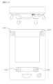
始めに、ぱちんこ遊技機Pの正面側の基本構造を説明する。ぱちんこ遊技機Pは、図1および図2に示すように、外郭方形に構成され、遊技施設において固定される外枠P1の開口前面に、外枠P1の開口に合わせたサイズで方形に構成された前枠P2が互いの正面左側縁部に配設された上下のヒンジ機構(上ヒンジ部10、下ヒンジ部20)により横開き開閉および着脱が可能に取り付けられる。
[Machine configuration of pachinko machines]
First, we will explain the basic structure of the front side of the pachinko machine P. As shown in Figures 1 and 2, the pachinko machine P is configured with a rectangular outer shell, and is attached to the front of the opening of the outer frame P1, which is fixed in the gaming facility, by upper and lower hinge mechanisms (
前枠P2には、遊技盤P5とガラス枠P3とが着脱可能にセットされている。ガラス枠P3は方形状であり、前枠P2の前面側に上下のヒンジ機構(上ヒンジ部10、下ヒンジ部20)を利用して横開き開閉および着脱可能に組み付けられて保持される。遊技盤P5は、前枠P2の前面側に着脱可能にセットされ、閉鎖保持されるガラス枠P3のガラスP301を通して遊技盤P5の正面側に設けられた遊技領域P501を遊技者が視認可能に構成されている。また前枠P2およびガラス枠P3は、ぱちんこ遊技機Pの正面右側縁部に設けられた施錠部P30の鍵穴に鍵を挿入し、左右方向のいずれかに回転させることで、回転方向に応じて、外枠P1と前枠P2の施錠が解除または前枠P2とガラス枠P3の施錠が解除される。具体例としては、施錠部P30の鍵穴に鍵を挿入して右方向に回転させると外枠P1と前枠P2の施錠が解除され、施錠部P30の鍵穴に鍵を挿入して左方向に回転させると前枠P2とガラス枠P3の施錠が解除されるようになっている。
The game board P5 and glass frame P3 are set removably on the front frame P2. The glass frame P3 is rectangular and is assembled and held on the front side of the front frame P2 using upper and lower hinge mechanisms (
ガラス枠P3の下部には、遊技球を貯留する上下の球皿P340(上球皿P341及び下球皿P342)が設けられる。またガラス枠P3には、遊技の展開状況に応じて発光する演出ランプP350や、遊技の展開状況に応じて効果音などの音を出力可能な上スピーカP370が設けられている。ガラス枠P3の下部中央には、所定の演出操作を行うための演出操作手段P380が取り付けられ、前提技術として示す本ぱちんこ遊技機が有する演出操作手段P380は、押下入力式のボタンP381と傾倒操作式のレバーP382とを備えており、ボタンP381は常時遊技者操作を可能とする一方、レバーP382はガラス枠に備えられた可動物(枠可動役物P360)の1つであり、操作手段自体が上方に突出した状態(入力許可状態)に変位した場合に操作入力を可能とする(1の演出操作手段にて、複数の操作が可能となっている)。 The lower part of the glass frame P3 is provided with upper and lower ball trays P340 (upper ball tray P341 and lower ball tray P342) for storing game balls. The glass frame P3 is also provided with a performance lamp P350 that emits light according to the development status of the game, and an upper speaker P370 that can output sounds such as sound effects according to the development status of the game. A performance operation means P380 for performing a predetermined performance operation is attached to the center of the lower part of the glass frame P3. The performance operation means P380 of the present pachinko game machine shown as the prerequisite technology has a push-in input button P381 and a tilt-operated lever P382. The button P381 allows the player to operate it at all times, while the lever P382 is one of the movable objects (frame movable role object P360) provided on the glass frame, and allows operation input when the operation means itself is displaced to a state in which it protrudes upward (input permitted state) (multiple operations are possible with one performance operation means).
前枠P2の右下部には、遊技球の発射操作および発射強度の調整を行うハンドルP204が設けられている。前枠P2の下部には、さらに発射装置ユニットP240を備え、図示を省略するが、上球皿P341に貯留された遊技球を1球ずつ送り出す球送り機構P241(球送りユニットと称する場合がある)、この球送り機構から送り出された遊技球を遊技領域P501へ向けて打ち出す発射機構(ロータリーソレノイドで駆動される打球槌)を有する発射装置P242、球送り機構P241や発射装置P242の作動を同期的に制御する発射制御基板P243などが設けられている。 At the bottom right of the front frame P2, a handle P204 is provided for adjusting the launching operation and launch strength of the game balls. At the bottom of the front frame P2, a launching device unit P240 is further provided, which, although not shown, includes a ball feed mechanism P241 (sometimes called a ball feed unit) that sends out the game balls stored in the upper ball tray P341 one by one, a launching device P242 having a launching mechanism (a hitting hammer driven by a rotary solenoid) that shoots the game balls sent out from the ball feed mechanism toward the play area P501, and a launch control board P243 that synchronously controls the operation of the ball feed mechanism P241 and the launching device P242.
遊技盤P5(遊技盤ユニット)は、図4に示すように、透明な合成樹脂や木材を用いて矩形の平板状に形成された基材をベースとして構成されている。なお、図1は遊技盤P5を含むぱちんこ遊技機Pを前面側から見た正面図であり、図4は遊技盤ユニットP5の斜視図を示す。図4は遊技盤ユニットに備えられた演出役物P560(「可動演出装置」「演出可動体」「演出可動役物」等とも呼ぶ)が動作している状態を図示している。遊技盤P5の前面には、左下部から右上部にかけて配設された円弧状の外レールP502と、遊技盤の下部中央付近から外レールP502の内側における左下部から左上部にかけて配設された円弧状の内レールP503と、右上部の外レールP502の端部から該盤面の下部までの間に配設されて左向きに開く湾曲形状に形成されたレール飾りP504とを備えており、外レールP502と内レールP503とレール飾りP504とで囲まれた内側に略円形の遊技領域P501が区画形成されている。この遊技領域P501は、略中央に配設される後述のセンター役物P540を基準として、センター役物P540の左側の領域である左側領域P501L(左打ち領域)と、センター役物の右側の領域である右側領域P501R(右打ち領域)とを有している。また、外レールと内レールとにより、発射装置ユニットP240により打ち出された遊技球を遊技領域P501へ案内するための案内通路が形成される。 As shown in Figure 4, the game board P5 (game board unit) is constructed based on a substrate formed into a rectangular flat plate using transparent synthetic resin or wood. Note that Figure 1 is a front view of the pachinko game machine P including the game board P5, and Figure 4 shows an oblique view of the game board unit P5. Figure 4 illustrates the state in which the performance device P560 (also called the "movable performance device," "performance movable body," "performance movable device," etc.) provided on the game board unit is in operation. The front of the game board P5 is provided with an arc-shaped outer rail P502 arranged from the lower left to the upper right, an arc-shaped inner rail P503 arranged from the lower center of the game board to the lower left to the upper left inside the outer rail P502, and a rail ornament P504 arranged between the end of the outer rail P502 at the upper right to the lower part of the board surface and formed in a curved shape opening to the left, and a substantially circular game area P501 is partitioned and formed inside surrounded by the outer rail P502, the inner rail P503, and the rail ornament P504. This game area P501 has a left area P501L (left hitting area) which is the area to the left of the center role P540, and a right area P501R (right hitting area) which is the area to the right of the center role P540, based on the center role P540 described later arranged in the approximately center. Additionally, the outer rail and the inner rail form a guide passage for guiding the game ball shot out by the launcher unit P240 to the game area P501.
遊技領域P501には、図示しない多数本の遊技釘P510や風車P511とともに、第1始動入賞口P711(第1始動口)、第2始動入賞口P721(第2始動口)、一般入賞口P731、普図作動口P741(普図作動ゲート装置)、大入賞口P751(アタッカー)、等の各種入球装置(賞球が発生する場合は「入賞装置」と称する)が配設されている。なお、大入賞口は1つとしてもよいし、複数有するよう構成してもよい。また、本明細書において、入球装置の構成上、遊技球が入球装置に入球した後に排出されるもの、入球装置に入球した後にさらに遊技領域P501を流下するもの(ゲートタイプ)に対し、遊技球が内部の検出スイッチで検出されることを「入球」「入賞(特に賞球が発生するもの)」と称し、ゲートタイプの入球口のように下流の遊技領域に流下するものついては、特に「通過」と区別して記載する場合を有する。また、入球装置を入球口、入賞装置を入賞口と称することがある。 In the game area P501, various winning devices (called "winning devices" when prize balls are generated) such as a first start winning port P711 (first start port), a second start winning port P721 (second start port), a general winning port P731, a general winning port P741 (a general winning gate device), and a large winning port P751 (attacker) are arranged, along with a large number of game nails P510 and windmills P511 (not shown). Note that there may be one large winning port, or there may be multiple large winning ports. In addition, in this specification, in terms of the configuration of the ball entry device, the game ball is detected by an internal detection switch as "entering" or "winning (especially winning balls)" in contrast to ball entry devices that are discharged after entering the ball entry device and ball entry devices that continue to flow down the game area P501 after entering the ball entry device (gate type), and balls that flow down to the downstream game area such as gate type ball entry ports are sometimes described as "passing through." Also, the ball entry device may be referred to as the ball entry port, and the winning device as the winning port.
また、遊技領域P501の右下には、第1特別図柄表示装置P51、第2特別図柄表示装置P52、普通図柄表示装置P53など、後述の主制御基板にて点灯制御される主制御表示装置P50が集約的に配設されている。遊技領域P501の略中央にはセンター役物P540が配設されており、このセンター役物P540の開口を通して演出表示装置P80の画面が視認可能に設けられている。このセンター役物P540の上部等には、遊技の展開状況に応じた演出動作を行う演出役物P560(可動役物装置)が設けられている。遊技領域P501の下端部には、各種入球装置の入賞口に入球せずに流下した遊技球が通過可能なアウト口P790が設けられている。各種入賞装置の入賞口に入球した遊技球又はアウト口P790に流入した遊技球は、遊技盤P5に前後貫通して形成された貫通孔(図示せず)を通じて遊技盤P5の後面側へ流下し、前枠P2下部の回収流路(遊技済み球通路)に収集され、発射した遊技球の総数を検出するための前枠下部に備えられたアウト球センサP792(発射球数センサ)を通過したのち遊技機外へ排出される。 In addition, at the bottom right of the game area P501, the main control display devices P50, such as the first special symbol display device P51, the second special symbol display device P52, and the normal symbol display device P53, which are controlled to be turned on by the main control board described below, are arranged in a concentrated manner. At approximately the center of the game area P501, a center role device P540 is arranged, and the screen of the performance display device P80 is arranged so that it can be seen through the opening of this center role device P540. At the top of this center role device P540, etc., a performance role device P560 (movable role device) that performs a performance operation according to the development status of the game is provided. At the bottom end of the game area P501, an out hole P790 is provided through which game balls that flow down without entering the winning holes of various ball entry devices can pass. Game balls that enter the winning ports of various winning devices or that flow into the outlet P790 flow down to the rear side of the game board P5 through through holes (not shown) formed in the front and rear of the game board P5, are collected in a recovery flow path (used ball passage) at the bottom of the front frame P2, and are discharged from the game machine after passing through an out ball sensor P792 (shot ball count sensor) provided at the bottom of the front frame to detect the total number of shot game balls.
第1始動入賞装置P710は、第1特別図柄遊技に対応する始動入賞装置として設けられている。この第1始動入賞装置P710には、遊技球が入球可能な第1始動入賞口P711が設けられている。第1始動入賞口P711への遊技球の入球は、第1特別図柄に係る抽選に使用される乱数の取得契機となっており、第1始動入賞口P711への遊技球の入球に基づいて入球直後のタイミングまたは保留期間を経過した後に第1特別図柄に係る抽選が実行される。 The first start winning device P710 is provided as a start winning device corresponding to the first special symbol game. This first start winning device P710 is provided with a first start winning port P711 into which a game ball can enter. The entry of a game ball into the first start winning port P711 triggers the acquisition of a random number used in a lottery for the first special symbol, and the lottery for the first special symbol is executed based on the entry of the game ball into the first start winning port P711 either immediately after the ball enters or after a holding period has elapsed.
第2始動入賞装置P720は、第2特別図柄遊技に対応する始動入賞装置として設けられている。この第2始動入賞装置P720には、遊技球が入球可能な第2始動入賞口P721および後述する普通図柄抽選に当選した場合に第2始動入賞口P721への入球を容易となる状態に切り替える可動体である普通電動役物P770が設けられている。第2始動入賞口P721への遊技球の入球は、第2特別図柄に係る抽選に使用される乱数の契機となっており、第2始動入賞口P721への遊技球の入球に基づいて入球直後のタイミングまたは保留期間を経過した後に第2特別図柄に係る抽選が実行される。第2始動入賞装置P721は、普通電動役物P770の作用により遊技球が第2始動入賞口P721へ入球可能又は入球容易な開状態と、遊技球が第2始動入賞口P721へ入球不能又は入球困難な閉状態とに変化する。つまり、第2始動入賞装置P720は、開状態に変位しなければ遊技球が第2始動入賞口へ入球し難い構造となっており、後述の所定の契機(普通図柄抽選に当選する契機)で開状態となると遊技球の入球容易性が高くなる。なお、普通電動役物P770の構造は様々な態様が知られており、可動体P771が開くことによる入球容易性の変化がなされる構造ではない場合があるため、「開状態」「閉状態」をそれぞれ「入球容易状態(入球容易態様)」「入球困難状態(入球困難態様)」と表記する場合を有する。 The second start winning device P720 is provided as a start winning device corresponding to the second special symbol game. This second start winning device P720 is provided with a second start winning port P721 into which a game ball can enter, and a normal electric device P770 which is a movable body that switches to a state in which the ball can enter the second start winning port P721 easily when the game ball wins the normal symbol lottery described later. The entry of the game ball into the second start winning port P721 is the trigger for the random number used in the lottery for the second special symbol, and the lottery for the second special symbol is executed based on the entry of the game ball into the second start winning port P721 at the timing immediately after the ball enters or after the holding period has elapsed. The second start winning device P721 changes between an open state where the game ball can or easily enter the second start winning port P721 and a closed state where the game ball cannot or has difficulty entering the second start winning port P721 by the action of the normal electric device P770. In other words, the second start winning device P720 is structured so that the game ball has difficulty entering the second start winning port unless it is displaced to the open state, and when it is opened by a predetermined opportunity (an opportunity to win the normal pattern lottery) described below, the game ball becomes easier to enter. Note that various forms of the structure of the normal electric device P770 are known, and there are cases where the structure does not change the ease of entry by opening the movable body P771, so the "open state" and "closed state" are sometimes written as "easy ball entry state (easy ball entry mode)" and "difficult ball entry state (difficult ball entry mode)", respectively.
一般入賞装置P730は、左打ち領域P501Lに配置された左側一般入賞装置P730Lと、右打ち領域P501Rに配置された右側一般入賞装置P730Rとを有している。本前提技術におけるぱちんこ遊技機Pにおいては、左側一般入賞装置P730Lとして、3つの一般入賞口P731La~P731Lcが1のユニットとして構成されている一方、右側一般入賞装置P730Rは後述する大入賞装置P750の一部として構成されている。一般入賞口P731への遊技球の入球は、他の入賞装置と同じく賞球払出の契機となる。なお、前提とするぱちんこ遊技機の一般入賞口P731の個数や位置はあくまで一例であり、右打ち領域P501Rにのみ配置されるよう構成する等としてもよい。 The general winning device P730 has a left general winning device P730L arranged in the left hitting area P501L and a right general winning device P730R arranged in the right hitting area P501R. In the pachinko game machine P in this premise technology, the left general winning device P730L is configured as one unit with three general winning ports P731La to P731Lc, while the right general winning device P730R is configured as part of the large winning device P750 described later. The entry of a game ball into the general winning port P731 triggers the payout of prize balls, just like other winning devices. Note that the number and location of the general winning ports P731 in the premise pachinko game machine are merely examples, and they may be configured to be arranged only in the right hitting area P501R.
普図作動ゲート装置P740(普図作動口)は、普通図柄遊技に対応する始動入球口として設けられている。この普図作動ゲート装置P740には、遊技球が通過可能な作動ゲートP741が設けられており、入球した遊技球は遊技盤の遊技領域の下流をさらに流下可能に構成されている。作動ゲートP741への遊技球の通過は、第2始動入賞装置P720を開状態とするか否か、すなわち普通電動役物P770を作動させるか否かを決定するための普通図柄抽選の契機となる。なお、変形例として普通図柄抽選の契機となる機能を前述した一般入賞口P731に備えるように構成することも可能であり、この場合には、普通図柄抽選を実行する機能に加えて、賞球を発生させる機能を1の入賞装置として設けることも可能である(普図作動入賞口)。 The normal symbol operation gate device P740 (normal symbol operation port) is provided as a start ball entry port corresponding to normal symbol play. This normal symbol operation gate device P740 is provided with an operation gate P741 through which the game ball can pass, and is configured so that the game ball that entered can flow further downstream of the game area of the game board. The passage of the game ball through the operation gate P741 triggers a normal symbol lottery to determine whether or not the second start winning device P720 is opened, that is, whether or not the normal electric role P770 is operated. As a modified example, it is also possible to configure the general winning port P731 described above to have a function that triggers the normal symbol lottery, and in this case, in addition to the function of executing the normal symbol lottery, it is also possible to provide a function of generating prize balls as one winning device (normal symbol operation winning port).
大入賞装置P750は、第1特別図柄抽選又は第2特別図柄抽選の抽選結果が大当りや小当りとなった場合に開閉動作する大入賞口P751(特別電動役物P755)を有して構成されており、「アタッカー(装置)」などと呼称する場合を有する。大入賞装置P750は、遊技球が大入賞口P751へ入球可能又は入球容易な開状態(例として特別電動役物が作動P755した状態)と、遊技球が大入賞口P751へ入球不能又は入球困難な閉状態(例として特別電動役物P755が非作動の状態)とに変化する。大当り遊技においては、大入賞口P751の開閉動作を伴う複数回のラウンド遊技(単位遊技)が行われる。なお、特別電動役物P755が作動した状態であっても、一連の作動パターン(「開放パターン」とも呼ぶ)により、大入賞口P751を構成する可動体P756が入球困難な閉態様となる場合を有する。 The big prize device P750 is configured with a big prize opening P751 (special electric device P755) that opens and closes when the result of the first special pattern lottery or the second special pattern lottery is a big prize or a small prize, and may be called an "attacker (device)". The big prize device P750 changes between an open state in which the game ball can or easily enters the big prize opening P751 (for example, a state in which the special electric device P755 is activated), and a closed state in which the game ball cannot or has difficulty entering the big prize opening P751 (for example, a state in which the special electric device P755 is not activated). In a big prize game, multiple rounds of play (unit games) involving the opening and closing of the big prize opening P751 are played. Even when the special electric device P755 is activated, a series of operating patterns (also called "opening patterns") may cause the movable body P756 that constitutes the large winning hole P751 to close, making it difficult for a ball to enter the hole.
また、大入賞装置P750には、遊技機の仕様(スペック)によっては、遊技球が通過可能な特定領域P760(「Vゾーン」、「V領域」と呼ばれ、機能によっては「確率変動機能作動領域」、「継続領域」などと呼ぶ)が設けられる場合を有する。この「特定領域」に関する機能として、(ア)大当り遊技中の特定領域に対する通過を契機として大当り遊技の後に確率変動機能(後述)を作動させること、(イ)小当り遊技中の特定領域の通過を契機として役物連続作動装置(特別電動役物を連続的に作動させるためのフラグ)を作動させ、大当り遊技を実行する権利を付与すること、(ウ)大当り遊技中の特定のラウンドにおいて特定領域を通過したか否かに基づいて、後続のラウンドの実行を確定的としたり、実行しないものとしたりすること、などが例として挙げられる。なお、「特定領域」に対し、通過の容易性を変化させるための構造体である開閉部材P761(弁部材)が設けられてもよく、開閉部材P761の作用により流下経路を振り分けられることで、特定領域P760又はそれ以外の非特定領域を通過するように構成してもよい。また、大当り遊技中や小当り遊技中において、特定領域P761の遊技球の通過が有効となる期間と無効となる期間とを有してもよい。 Depending on the specifications of the gaming machine, the big prize device P750 may be provided with a specific area P760 (called a "V zone" or "V area"; depending on the function, it may be called a "probability fluctuation function activation area" or "continuation area") through which the gaming ball can pass. Examples of functions related to this "specific area" include (a) activating a probability fluctuation function (described below) after a big win game when the ball passes through a specific area during a big win game, (b) activating a role-continuous activation device (a flag for continuously activating a special electric role) when the ball passes through a specific area during a small win game, and granting the right to play a big win game, and (c) making the execution of a subsequent round definite or not based on whether or not a specific area has been passed in a specific round during a big win game. In addition, an opening/closing member P761 (valve member), which is a structure for changing the ease of passage, may be provided for the "specific area", and the flow path may be divided by the action of the opening/closing member P761, so that the ball passes through the specific area P760 or a non-specific area other than the specific area. Also, during a big win game or a small win game, there may be periods during which the passage of the game ball through the specific area P761 is valid and periods during which it is invalid.
なお、前提とするぱちんこ遊技機Pにおいて、大入賞装置P750は、遊技領域P501における右側領域P501R(右打ち領域)に設けられている。そのため、大当り遊技又は小当り遊技では、遊技領域P501に向けて遊技球を発射する際に、右側領域P501Rを狙って打つ、いわゆる右打ちを行うことで大入賞口P751への入球が容易となっている。 In the pachinko game machine P, the big prize device P750 is provided in the right area P501R (right-hand hit area) of the game area P501. Therefore, in a big prize game or a small prize game, when a game ball is shot toward the game area P501, it is easy to enter the big prize opening P751 by aiming at the right area P501R, i.e., hitting from the right.
続いて、前提とするぱちんこ遊技機Pの背面側の基本構造を説明する。前枠の背面側には、中央に遊技盤ユニットP5を取り付けるために前後連通する窓口を有した裏セットユニットP4が取り付けられている。裏セットユニットP4には、遊技施設側から供給される多数個の遊技球を貯留する貯留タンクP401、貯留タンクP401からの遊技球を流下させる樋部材P402、樋部材により導かれた遊技球を払い出す賞球払出ユニットP410、賞球払出ユニットP410から払い出された遊技球を上球皿P341又は下球皿P342へ流下させる裏側通路部材P403などが設けられている。また、貯留タンクP401から球皿P340までの遊技球流下経路上には、球抜き機構(球抜き操作レバーP405、操作レバーに連動して遊技球を流路上から排除する流路を形成する弁部材P406)が設けられている。 Next, the basic structure of the rear side of the pachinko game machine P will be described. A rear set unit P4 with a window that communicates front and rear is attached to the rear side of the front frame to attach the game board unit P5 in the center. The rear set unit P4 is provided with a storage tank P401 that stores a large number of game balls supplied from the game facility, a gutter member P402 that allows the game balls from the storage tank P401 to flow down, a prize ball payout unit P410 that pays out the game balls guided by the gutter member, and a rear passage member P403 that allows the game balls paid out from the prize ball payout unit P410 to flow down to the upper ball tray P341 or the lower ball tray P342. In addition, a ball removal mechanism (a ball removal operation lever P405, a valve member P406 that forms a flow path that removes game balls from the flow path in conjunction with the operation lever) is provided on the game ball flow path from the storage tank P401 to the ball tray P340.
遊技盤P5の背面側には、ぱちんこ遊技機Pの遊技進行を統括的に制御する主制御基板P40や、主制御基板P40の制御に伴う遊技進行に合わせた演出全般の制御を行う演出制御基板P41、遊技展開に応じた画像表示の制御を行う画像制御基板P42などが取り付けられている。なお、本前提技術のぱちんこ遊技機Pでは、演出制御基板P41および画像制御基板P42は、演出表示装置P80(液晶表示装置)と一体化されたアッセンブリ状態で演出表示ユニットを構成している。これに対して、裏セットユニットP4の背面側には、遊技球の払い出しに関する制御を行う払出制御基板P43や、遊技施設側から受電して各種制御基板や電気・電子部品に電力を供給する電源基板P44(図示せず)などが取り付けられている。なお、これらの制御基板は、不正改造防止のため、カシメ構造及び封印シール構造を有する透明樹脂製の基板ケースに収容されたアッセンブリ状態で遊技盤P5の背面又は裏セットユニットP4の背面の所定位置にそれぞれ配設される。これらの制御基板とぱちんこ遊技機各部の電気・電子部品とがハーネス(コネクタケーブル)を介して相互に接続されて、ぱちんこ遊技機Pにおける遊技の進行や、演出の実行が可能に構成されている。 On the rear side of the game board P5, there are attached a main control board P40 that controls the overall game progress of the pachinko game machine P, a performance control board P41 that controls the overall performance in accordance with the game progress according to the control of the main control board P40, and an image control board P42 that controls the image display according to the game development. In the pachinko game machine P of the present premise technology, the performance control board P41 and the image control board P42 are integrated with the performance display device P80 (liquid crystal display device) to form a performance display unit in an assembled state. On the other hand, on the rear side of the back set unit P4, there are attached a payout control board P43 that controls the payout of game balls, and a power supply board P44 (not shown) that receives power from the game facility and supplies power to various control boards and electric and electronic components. To prevent unauthorized modification, these control boards are housed in a transparent resin board case with a crimping structure and a sealing seal structure in an assembled state and are disposed in a predetermined position on the back of the game board P5 or the back of the back set unit P4. These control boards and the electrical and electronic components of each part of the pachinko game machine are connected to each other via harnesses (connector cables), allowing the game to proceed on the pachinko game machine P and effects to be executed.
[機能ブロック]
図5は、前提とするぱちんこ遊技機の機能ブロックを示す。
[Function block]
FIG. 5 shows the functional blocks of the assumed pachinko gaming machine.
ぱちんこ遊技機は、遊技機外部から供給される交流電源に基づいて遊技機内で使用する電源を生成する電源基板P44と、遊技の基本動作や遊技の進行を制御する主制御基板P40(主制御CPU)と、賞球の払出しや遊技球の発射を制御する枠制御装置としての払出制御基板P43(払出制御CPU)と、演出的な動作や処理を制御する演出制御基板P41とに機能を分担させた形態で構成される。なお、図中に示す矢印は機能別に、上方の送受信の関係を実線矢印で示し、電気的接続の関係を破線矢印にて示している。 The pachinko machine is configured with functions shared among a power supply board P44 that generates power for use within the machine based on AC power supplied from outside the machine, a main control board P40 (main control CPU) that controls the basic game operations and game progress, a payout control board P43 (payout control CPU) that acts as a frame control device that controls the payout of prize balls and the launch of game balls, and a presentation control board P41 that controls presentation operations and processing. Note that the arrows in the figure are divided by function, with solid arrows indicating the relationship between transmission and reception at the top and dashed arrows indicating the relationship of electrical connections.
電源基板P44は、基板上に設けられた電源スイッチP47を操作することによって、後述する主制御基板P40、演出制御基板P41、払出制御基板P43、並びにそれらに電気的に接続する各種遊技用装置に対し、動作に必要となる電力を生成して供給する。詳細は後述するが、電源スイッチP47の電源投入操作は、遊技機の設定に係る情報の処理の開始契機となるスイッチ操作であるため、電源スイッチは不正な操作を防止するため開閉カバーに覆われた状態で保護されている。 By operating the power switch P47 provided on the power supply board P44, the power supply board P44 generates and supplies the power required for the operation of the main control board P40, the presentation control board P41, the payout control board P43, and the various gaming devices electrically connected to them, which will be described later. As will be described in more detail below, the power-on operation of the power switch P47 is the switch operation that triggers the processing of information related to the gaming machine settings, the power switch is protected by an opening and closing cover to prevent unauthorized operation.
主制御基板P40は、第1始動入賞口P711(特図1始動口スイッチP712)、第2始動入賞口P721(特図2始動口スイッチP722)、大入賞口P751(大入賞口スイッチP752)、普図作動口P741(普図作動口スイッチP742)や、その他の検出スイッチである一般入賞口P731(左側一般入賞口,右側一般入賞口)、アウト口P790などの各種の遊技進行に係る検出スイッチや、設定キースイッチP49、振動検知センサP72、磁石センサP73などの各種遊技の管理や不正監視に用いられるスイッチやセンサと接続される。主制御基板は、これらのスイッチから各種の遊技状態の発生に係る情報の入力を得て、遊技進行に係る制御内容の決定をするとともに、ソレノイド等で構成され、大当りや小当りの際に大入賞口P751を拡開させるために駆動される特別電動役物駆動手段P70や、普通図柄抽選に当選した場合に普通電動役物P770を入球容易状態とするために駆動される普通電動役物駆動手段P71といった遊技用装置に対して、駆動態様に係る情報の出力を行う。
The main control board P40 is connected to various detection switches related to the progress of games, such as the first start winning port P711 (
主制御基板P40に接続するセンサ等は、主制御基板上の入力ポートと呼ばれる端子に接続して、センサ検出に基づく各種遊技状態の発生の有無を主制御基板P40に情報として通知し、特別電動役物駆動手段P70や、普通電動役物駆動手段P71、その他、発射装置P242に対する発射許可信号などを出力ポートと呼ばれる端子から出力された情報を受け取ってそれぞれの装置、デバイスを制御する。 Sensors and other devices connected to the main control board P40 are connected to terminals called input ports on the main control board, and notify the main control board P40 of the occurrence or non-occurrence of various game states based on sensor detection, and receive information output from terminals called output ports, such as the special electric role drive means P70, the normal electric role drive means P71, and other information such as launch permission signals for the launch device P242, to control the respective devices and equipment.
また、主制御基板P40は、第1特別図柄や第2特別図柄の変動表示を行う特別図柄表示装置P51、P52や大当りや小当りの種類(ラウンド数)を報知するラウンド表示灯P54、遊技状態を報知する状態表示灯P55などの各種表示を行う主制御表示装置P50や、遊技機の性能(例えば通常遊技中におけるベース値、すなわち発射総数に対する賞球数の割合)を表示する性能表示装置P59などと接続する。なお、「ベース値」に関して、始動入賞口P711等の入賞を除外して計上するデータなど、他の計上方法も多種存在するが、本件発明にて必要な場合に別途説明を行い、前提とするぱちんこ遊技機の説明では詳細は割愛する。 The main control board P40 is also connected to the main control display device P50, which displays various information such as the special symbol display devices P51 and P52 that display the variation of the first and second special symbols, the round indicator light P54 that indicates the type of big win or small win (number of rounds), and the status indicator light P55 that indicates the game status, as well as the performance display device P59 that displays the performance of the gaming machine (for example, the base value during normal play, i.e., the ratio of the number of winning balls to the total number of shots). Note that there are many other methods of recording the "base value," such as data that excludes winnings from the start winning slot P711, etc., but these will be explained separately when necessary for this invention, and details will be omitted in the explanation of the pachinko gaming machine that is the premise of the invention.
主制御基板P40は、上記の他に外部情報出力端子P77や試験端子P78等により遊技機外部の装置と電気的に接続可能に構成されており、各々との間で各種制御信号を送受信する。また、主制御基板P40は、遊技機内の他の制御基板である演出制御基板P41、払出制御基板P43とも電気的に接続している。 The main control board P40 is also configured to be electrically connectable to devices external to the gaming machine via an external information output terminal P77, a test terminal P78, etc., and transmits and receives various control signals between them. The main control board P40 is also electrically connected to the other control boards within the gaming machine, the performance control board P41 and the payout control board P43.
払出制御基板P43は、主制御基板P40から送信される賞球払出や主制御基板の制御状態を示す信号等に基づいて、払出装置P410による賞球の払出を制御するほか、遊技者によるハンドルP204の操作を受けて発射装置ユニットP240による遊技球の発射に係る制御を行う。払出装置P410は、一例として払出モータP411と球計数センサP412有するものであり、払出モータP411の回転により、遊技球を1球ずつ払出可能に構成される。発射装置(発射装置ユニット)P240は、球皿P340(上球皿P341)に滞留している遊技球を1球ずつ球送りユニットP241によって発射可能位置へ移動させた後、打球槌を遊技球にぶつけることで遊技球を発射させるよう構成されている。なお、払出制御基板P43には、主として遊技機の初期化や、遊技中に発生したエラーの解除に用いられるラムクリアスイッチP48が配設されており、払出制御基板P43と主制御基板P40の接続に使用されるハーネスやコネクタを介して、ラムクリアスイッチP48の操作情報が主制御基板に入力されるようになっている。 The payout control board P43 controls the payout of prize balls by the payout device P410 based on signals indicating the payout of prize balls and the control status of the main control board transmitted from the main control board P40, and also controls the launch of game balls by the launch device unit P240 in response to the operation of the handle P204 by the player. The payout device P410 has, as an example, a payout motor P411 and a ball counting sensor P412, and is configured to be able to pay out game balls one by one by the rotation of the payout motor P411. The launch device (launch device unit) P240 is configured to move the game balls remaining in the ball tray P340 (upper ball tray P341) one by one to a launchable position by the ball feed unit P241, and then launch the game balls by hitting the game balls with a striking hammer. In addition, the payout control board P43 is equipped with a RAM clear switch P48 that is primarily used to initialize the gaming machine and clear errors that occur during play, and operation information for the RAM clear switch P48 is input to the main control board via the harness and connector used to connect the payout control board P43 and the main control board P40.
演出制御基板P41は、演出表示装置P80、演出可動役物P560の駆動源や位置検出センサ(例えば、駆動モータや、初期位置検出センサ、演出位置検出センサ)、スピーカP83(上スピーカP370、下スピーカ141)、演出入力装置ユニットP380(例えば演出操作手段P81である演出ボタンP381、演出レバーP382、十字キーP383など)、演出ランプP82(「装飾ランプ」「盤ランプ(P550)」「枠ランプ(P350)」とも称する)と電気的に接続されており、各々との間で各種制御信号を送受信する。また、演出制御基板P42と、演出表示装置P80の接続は、演出表示装置P80(例えば液晶表示装置などの画像を表示する装置)の表示制御を行う画像制御基板P42(VDP)などを介して接続するものであってもよい。また、本前提とするぱちんこ遊技機では、スピーカP83を演出制御基板P41にて制御するように構成するものであるが、音声制御用のIC等を備えた音声制御基板を別途設けてスピーカP83を制御するように構成してもよい。 The performance control board P41 is electrically connected to the performance display device P80, the driving source and position detection sensor of the performance movable prop P560 (e.g., a drive motor, an initial position detection sensor, a performance position detection sensor), the speaker P83 (upper speaker P370, lower speaker 141), the performance input device unit P380 (e.g., the performance button P381, which is the performance operation means P81, the performance lever P382, the cross key P383, etc.), and the performance lamp P82 (also called "decorative lamp", "board lamp (P550)", "frame lamp (P350)"), and transmits and receives various control signals between each of them. In addition, the connection between the performance control board P42 and the performance display device P80 may be made via an image control board P42 (VDP) that controls the display of the performance display device P80 (e.g., a device that displays images such as a liquid crystal display device). In addition, in the pachinko game machine that is the premise of this embodiment, the speaker P83 is configured to be controlled by the performance control board P41, but it may also be configured to control the speaker P83 by providing a separate audio control board equipped with an IC for audio control, etc.
主制御基板P40と演出制御基板P41の間におけるデータの送受信は主制御基板P40から演出制御基板P41への一方向となるよう一方向でのデータ送受信にて行われる。主制御基板P40から演出制御基板P41へのデータ送信の一方向性が保たれるため、演出制御基板P41に含まれる構成から主制御基板P40に含まれる構成へはデータを送信することができず、データ送信の要求もできない。したがって、演出制御基板P41は、主制御基板P40で生成された情報が送信されない限りその情報を参照することはできない。なお、本前提とするぱちんこ遊技機Pにおいては、主制御基板P40と払出制御基板P43の間は、双方向でデータ送受信がなされる。ただし、主制御基板P40と演出制御基板P41の間と同様、主制御基板P40から払出制御基板P43への一方向でのデータ送受信とする構成にしてもよい。 Data transmission between the main control board P40 and the performance control board P41 is performed in one direction, from the main control board P40 to the performance control board P41. Since the one-way data transmission from the main control board P40 to the performance control board P41 is maintained, data cannot be transmitted from the configuration included in the performance control board P41 to the configuration included in the main control board P40, and data transmission cannot be requested. Therefore, the performance control board P41 cannot refer to information generated by the main control board P40 unless that information is transmitted. Note that in the pachinko game machine P, which is the premise of this embodiment, data is transmitted in both directions between the main control board P40 and the payout control board P43. However, as with the main control board P40 and the performance control board P41, data may be transmitted in one direction from the main control board P40 to the payout control board P43.
[基本遊技進行]
次に、以上のように構成される前提技術としてのぱちんこ遊技機Pにおける、基本的な遊技進行および遊技方法に関して遊技状態別に説明する。「遊技状態」としては大別して「通常遊技状態」と、通常遊技状態と比して遊技球を獲得することが容易な「特別遊技状態」とがある。「通常遊技状態」は、「特別遊技状態」への移行権利の獲得を目指す状態であり、通常遊技状態の中でも、特別遊技状態への移行権利の獲得に関して遊技者にとって有利度合いが異なる遊技状態が複数設けられており、複数の通常遊技状態の中でも、遊技者にとって比較的特別遊技状態への移行権利が獲得容易な状態(通常遊技状態(低確率/低ベース状態)よりも遊技者にとって有利な状態)に関して「特定遊技状態」と表現する。「特別遊技状態」は、いわゆる「大当り遊技」と「小当り遊技」が該当し、主制御基板P40によって特別電動役物駆動手段P70が駆動され大入賞口P751が開口した状態となり遊技球の獲得が容易となる状態のことを意味している。
[Basic gameplay]
Next, the basic game progress and game method in the pachinko game machine P as the prerequisite technology configured as above will be explained for each game state. The "game state" is roughly divided into a "normal game state" and a "special game state" in which it is easier to acquire game balls compared to the normal game state. The "normal game state" is a state in which the player aims to acquire the right to transition to the "special game state", and among the normal game states, there are multiple game states that have different degrees of advantage for the player in acquiring the right to transition to the special game state, and among the multiple normal game states, a state in which it is relatively easy for the player to acquire the right to transition to the special game state (a state that is more advantageous for the player than the normal game state (low probability/low base state)) is expressed as a "specific game state". The "special game state" refers to the so-called "big win game" and "small win game," in which the special electric device drive means P70 is driven by the main control board P40, causing the big prize opening P751 to open, making it easy to obtain game balls.
[通常遊技状態(低確率/低ベース状態)]
まず、通常遊技状態における遊技方法および遊技の進行に関する説明を行う。なお、ここで記載する通常遊技状態は特定遊技状態を除く「通常遊技状態(低確率/低ベース状態)」(図6参照)に関する説明であり、一般的に遊技者が遊技を開始する状況における遊技状態について説明するものであり、特定遊技状態における遊技方法、遊技の進行、および「低(高)確率」、「低(高)ベース」の用語の意味に関しては後述する。
[Normal game state (low probability/low base state)]
First, the game method and game progress in the normal game state will be explained. The normal game state described here is an explanation of the "normal game state (low probability/low base state)" (see FIG. 6) excluding the specific game state, and generally describes the game state in the situation where the player starts playing. The game method and game progress in the specific game state, and the meaning of the terms "low (high) probability" and "low (high) base" will be described later.
通常遊技状態(低確率/低ベース状態)における、遊技の方法として、まず、遊技者はハンドルP204を操作して遊技盤P5に設けられた遊技領域P501に向けて遊技球を発射する。前提とするぱちんこ遊技機Pにおいては、通常遊技状態(低確率/低ベース状態)において、遊技者はハンドルP204の操作量を遊技球が遊技領域の左側領域P501L(左打ち領域)に向かって発射されるように操作して遊技を行う。 In the normal game mode (low probability/low base state), the method of playing is as follows: first, the player operates the handle P204 to launch the game ball toward the game area P501 provided on the game board P5. In the assumed pachinko game machine P, in the normal game mode (low probability/low base state), the player plays the game by operating the handle P204 so that the game ball is launched toward the left side area P501L (left hitting area) of the game area.
遊技者によって遊技領域の左側領域P501Lに遊技球が発射されると、発射された遊技球は、遊技領域P501を流下し、図示しない遊技釘P510(「障害釘」、「釘」とも呼ぶ)や、風車P511によって流下方向を変位させながら、「ヘソ」などと呼ばれる遊技盤の遊技領域P501における略中央下位置に配置された第1始動入賞口P711、あるいは左側一般入賞装置の一般入賞口P731Lに入球(入賞)するか、いずれの入賞口にも入球せず、遊技済み遊技球としてアウト口P790へ入球する。第1始動入賞口P711あるいは、一般入賞口P731へ入球すると、主制御基板P40は、払出制御基板P43に対し入賞口毎に定められた賞球数の賞球をさせるための情報(制御コマンド)を出力し、遊技者は賞球払出により新たな遊技球を獲得する。 When a game ball is launched into the left area P501L of the game area by a player, the launched game ball flows down the game area P501 and is displaced in the direction of flow by the game nails P510 (not shown) (also called "obstacle nails" or "nails") and the windmill P511, and enters (wins) the first start winning hole P711 located at the approximately lower center of the game area P501 of the game board, which is called the "navel," or the general winning hole P731L of the left general winning device, or does not enter either winning hole and enters the out hole P790 as a played game ball. When the ball enters the first start winning hole P711 or the general winning hole P731, the main control board P40 outputs information (control command) to the payout control board P43 to play the number of winning balls set for each winning hole, and the player acquires new game balls by paying out the winning balls.
ここで第1始動入賞口P711の内部には特図1始動口スイッチP712が配置されており、遊技者が遊技領域における左側領域P501Lに遊技球を発射して生じ得る遊技状態(遊技結果)として、第1始動入賞口P711への入球がなされた場合において、主制御基板P40に特図1始動口スイッチP712の遊技球検出情報が入力される。 Here, a special 1 start port switch P712 is arranged inside the first start winning port P711, and when a player shoots a game ball into the left area P501L in the game area, which is a possible game state (game result), and the ball enters the first start winning port P711, game ball detection information of the special 1 start port switch P712 is input to the main control board P40.
主制御基板P40は、特図1始動口スイッチP712の遊技球検出情報の入力を受けると、予め定められた賞球数の遊技球の払い出しを行うほか、第1特別図柄の制御に係る抽選を行うための乱数値を取得する。乱数値の取得は、遊技球の検出に基づいて、電気回路上で乱数生成回路の生成する乱数値を取得するもの(ハードラッチ)や、主制御基板P40の制御装置がソフト上の処理にて遊技球の検出情報を確認した際に乱数値を先の乱数生成回路から取得する処理を実行したり、ソフト的に更新されている乱数値を取得したりするもの(ソフトラッチ)などの手法があり、取得する乱数値に応じて使い分けてもよいし、組み合わせて使用することも可能である。なお、一般入賞口に入球した場合には、特別図柄に係る乱数は取得されず、賞球の払い出しのみが行われる。
When the main control board P40 receives the game ball detection information input from the
第1特別図柄の制御に係る抽選は、「特別図柄抽選」であり、「特別図柄抽選」には、「当否抽選」、「当り図柄抽選」、「変動パターン抽選」が含まれる。「当否抽選」は、取得した乱数値を用いた抽選結果が「大当り」であるか「はずれ」であるかを決定する処理である(遊技機の仕様によっては抽選結果に「小当り」を含む)。「当り図柄抽選」(単に「図柄抽選」と呼ぶ場合もある)は、主制御表示装置P50における特別図柄表示装置P51(P52)において当否抽選結果を示す停止表示図柄の表示パターンを決定する処理であり、1の抽選結果(大当り、小当り)に対し、複数の停止表示図柄から1の図柄を決定可能であり、ここで決定された停止表示図柄に応じて、「大当り」、「小当り」における特別遊技の実行態様を異ならしめることを可能としている。「変動パターン抽選」は、特別図柄表示装置P51(P52)において当否抽選の結果を示す停止表示図柄をどのタイミングで表示させるかを決定する処理であり、特別図柄表示装置P51(P52)において特別図柄抽選が実行されたことを示す変動表示がなされる時間(「変動表示時間」、「変動パターン」と呼ぶ)を決定するものである。「当否抽選」、「当り図柄抽選」、「変動パターン抽選」に使用される乱数値は異なるものを使用するのが一般的であり、それぞれ「当否抽選乱数」、「図柄乱数」、「変動パターン乱数」と呼ばれる。なお、特図2始動口スイッチP722の遊技球を検出することに基づいて行われる第2特別図柄の制御に係る抽選もまた、同様の「特別図柄抽選」である。また、「特別図柄抽選」に関する説明は後述する。
The lottery for controlling the first special symbol is a "special symbol lottery", which includes a "win/lose lottery", a "win pattern lottery", and a "variable pattern lottery". A "win/lose lottery" is a process that uses an acquired random number value to determine whether the lottery result is a "jackpot" or a "lose" (depending on the specifications of the gaming machine, the lottery result may include a "small win"). A "win pattern lottery" (sometimes simply called a "pattern lottery") is a process that determines the display pattern of the stop display pattern that indicates the win/lose lottery result on the special pattern display device P51 (P52) in the main control display device P50, and it is possible to determine one pattern from multiple stop display patterns for one lottery result (jackpot, small win), and it is possible to differ the execution mode of the special game in the "jackpot" and "small win" depending on the stop display pattern determined here. The "variable pattern lottery" is a process that determines the timing of displaying the stop display pattern indicating the result of the win/lose lottery on the special pattern display device P51 (P52), and determines the time (called the "variable display time" or "variable pattern") at which the variable display indicating that the special pattern lottery has been executed is displayed on the special pattern display device P51 (P52). Different random numbers are generally used for the "win/lose lottery", "win pattern lottery", and "variable pattern lottery", and are called the "win/lose lottery random number", "pattern random number", and "variable pattern random number", respectively. The lottery for controlling the second special pattern, which is performed based on the detection of the game ball on the
通常遊技状態(低確率/低ベース状態)における遊技方法の説明に戻って説明すると、通常遊技状態(低確率/低ベース状態)においては、遊技者は遊技領域の左側領域P501Lに遊技球を発射し、第1始動入賞口P711へ遊技球を入球させ、第1特別図柄に係る抽選(特別図柄抽選)を実行させ、特別図柄表示装置において「大当り」(「小当り」)を示す特別図柄の停止表示図柄が表示されることにより、特別遊技の実行権利の獲得を目指す遊技が行われる。 Returning to the explanation of the game method in the normal game state (low probability/low base state), in the normal game state (low probability/low base state), the player shoots the game ball into the left area P501L of the game area, causing the game ball to enter the first start winning port P711, causing a lottery for the first special pattern (special pattern lottery), and a special pattern stop display pattern indicating a "big win" ("small win") is displayed on the special pattern display device, thereby playing a game with the aim of acquiring the right to play the special game.
なお、遊技者が特別図柄抽選を受ける過程において、変動パターン抽選により決定された時間に応じて特別図柄の変動表示がなされる点について上述しているが、前提とするぱちんこ遊技機Pにおいては、この特別図柄の変動表示期間において、新たに始動入賞口(第1始動入賞口P711、第2始動入賞口P721)に入球があった場合には、予め定められた回数の特別図柄抽選の実行権利に対応する乱数値を一時的に記憶する保留機能を備えている。前提とするぱちんこ遊技機Pでは、第1始動入賞口P711の入賞に基づく特別図柄抽選に対応する保留機能として、最大4回の特別図柄抽選を保留することを可能としている。なお、保留機能は特別図柄毎に設定可能であり、本前提技術のぱちんこ遊技機Pでは、第1特別図柄の保留とは別に、第2特別図柄に対する特別図柄抽選の保留機能も、最大4回の特別図柄抽選に使用する乱数値を保留しておくことを可能としている。 As mentioned above, the special symbol is displayed in a variable manner according to the time determined by the variable pattern lottery during the process in which the player receives the special symbol lottery. In the pachinko game machine P, if a new ball enters the start winning slot (first start winning slot P711, second start winning slot P721) during the period in which the special symbol is displayed in a variable manner, the pachinko game machine P has a hold function that temporarily stores a random number value corresponding to the right to execute a predetermined number of special symbol lotteries. In the pachinko game machine P, the hold function corresponding to the special symbol lottery based on the winning of the first start winning slot P711 makes it possible to hold up to four special symbol lotteries. The hold function can be set for each special symbol, and in the pachinko game machine P of the present premise technology, in addition to the hold function for the first special symbol, the hold function for the special symbol lottery for the second special symbol also makes it possible to hold the random number value used for up to four special symbol lotteries.
このように、通常遊技状態(低確率/低ベース状態)においては、遊技者は、遊技領域の左側領域P501Lに遊技球を発射して、第1特別図柄に係る特別図柄抽選を実行させる。そして、特別図柄抽選において、「大当り」や「小当り」などの特別遊技状態となる抽選結果に当選し、特別遊技状態への移行の権利を獲得したことが特別図柄表示装置に表示されると、ぱちんこ遊技機Pの遊技状態は特別遊技状態へ移行する。 Thus, in the normal game state (low probability/low base state), the player fires the game ball into the left area P501L of the game area to execute a special pattern lottery for the first special pattern. Then, in the special pattern lottery, if the player wins a lottery result that results in a special game state such as a "big win" or "small win," and the special pattern display device displays that the player has gained the right to transition to the special game state, the game state of the pachinko game machine P transitions to the special game state.
[特別遊技状態]
続いて、特別遊技状態における遊技方法および遊技の進行に関する説明を行う。特別遊技状態には「大当り(遊技)」と、「小当り(遊技)」とが存在するが、ともに特別電動役物P755が作動して、すなわち主制御基板P40から特別電動役物駆動手段P70に対して駆動信号が出力されて大入賞口P751が入球容易状態となる状態であり、その相違点として、「大当り」が複数回の特別電動役物P755を連続して作動させる役物連続作動装置の作動に基づくものであるのに対し、「小当り」が1回の特別電動役物の作動により終了する点が大きな相違点である。その他の相違点としては、役物連続作動装置の作動に基づく特別電動役物の作動(大当り)では、特別電動役物P755の作動に関し、より遊技者に有利な作動態様とすることを可能とする点にあり、具体的には、役物連続作動装置の作動状態(大当り)における大入賞口P751の総開放時間は、30秒まで許容される一方、小当りにおける大入賞口P751の総開放時間は1.8秒までに制限される点がある。以下の特別遊技状態における遊技方法および遊技の進行に関する説明では、大当りを例に説明を行う。
[Special game state]
Next, the game method and game progress in the special game state will be explained. In the special game state, there are a "big win (game)" and a "small win (game)", but in both cases, the special electric role P755 is operated, that is, a drive signal is output from the main control board P40 to the special electric role drive means P70, and the big prize winning port P751 is in a state where it is easy to enter the ball. The big difference between them is that the "big win" is based on the operation of the role continuous operation device that operates the special electric role P755 several times in succession, while the "small win" ends with one operation of the special electric role. Another difference is that in the operation of the special electric role (jackpot) based on the operation of the role continuous operation device, the special electric role P755 can be operated in a more advantageous manner for the player, specifically, the total opening time of the big prize winning port P751 in the operation state of the role continuous operation device (jackpot) is allowed to be up to 30 seconds, while the total opening time of the big prize winning port P751 in the small prize is limited to 1.8 seconds. In the following explanation of the game method and game progress in the special game state, an explanation will be given using a jackpot as an example.
前提技術のぱちんこ遊技機Pにおける特別遊技の遊技進行は、時系列に沿って、「特別遊技開始デモ」(大当りの場合は「大当り開始デモ」、「役連作動開始デモ」などと称し、小当りの場合は「小当り開始デモ」)と呼ばれる遊技者に各種特別遊技を獲得した旨を報知するための演出期間と、「ラウンド(遊技)」(「単位遊技」とも称する)と呼ばれる1回の特別電動役物P755の作動期間と、「特別遊技終了デモ」(大当りの場合は「大当り終了デモ」、「役連作動終了デモ」などと称し、小当りの場合は「小当り終了デモ」)と呼ばれる主に特別遊技中における遊技結果(獲得遊技球数など)および移行先の通常遊技状態(特定遊技状態を含む)の種類に係る報知を行うための期間とによって構成される。 The progress of the special game in the pachinko game machine P of the premise technology is composed of, in chronological order, a presentation period called the "special game start demo" (in the case of a big win, it is called the "big win start demo" or "linked role operation start demo", and in the case of a small win, it is called the "small win start demo") for notifying the player that various special games have been won, a period called a "round (game)" (also called a "unit game") in which the special electric role device P755 operates once, and a period called the "special game end demo" (in the case of a big win, it is called the "big win end demo" or "linked role operation end demo", and in the case of a small win, it is called the "small win end demo") for notifying the player of the game result (number of game balls won, etc.) during the special game and the type of normal game state (including specific game state) to which the player will transition.
次に上述した各特別遊技の期間における遊技の方法について説明を行う。まず、「特別遊技開始デモ」期間において、前提技術のぱちんこ遊技機Pでは、大入賞口P751が遊技領域の右側領域P501R(右打ち領域)に配置されており、通常遊技状態(低確率/低ベース状態)と同様の左側領域P501Lに遊技球を発射しても大入賞口P751の入球がほとんど期待できないため、特別遊技において大入賞口P751が入球容易状態となるラウンド遊技が開始する前に、遊技者に対して遊技領域の右側領域P501R(右打ち領域)に遊技球を発射することを促す右打ち報知演出を演出表示装置P80やスピーカ(下スピーカP141、上スピーカP370)、演出ランプP82を用いて実行する。遊技者は、右打ち報知演出に従って、ハンドルP204の操作量を増やし遊技球の発射強度を高めるよう調整し、遊技球を遊技領域の右側領域P501R(右打ち領域)に流下するよう発射位置を変更する(右打ちを実行する)。 Next, the method of playing during each of the above-mentioned special games will be explained. First, during the "special game start demo" period, in the pachinko game machine P of the premise technology, the large prize winning port P751 is located in the right area P501R (right-hitting area) of the game area, and since it is almost impossible to expect a ball to enter the large prize winning port P751 even if the game ball is shot into the left area P501L similar to the normal game state (low probability/low base state), a right-hitting notification effect is executed using the effect display device P80, speakers (lower speaker P141, upper speaker P370), and effect lamp P82 to encourage the player to shoot the game ball into the right area P501R (right-hitting area) of the game area before the round game begins in the special game, when the large prize winning port P751 is in a state where it is easy to enter the ball. In response to the right-hit notification, the player increases the amount of operation of the handle P204 to adjust the strength of the game ball's launch, and changes the launch position so that the game ball flows down into the right-side area P501R (right-hit area) of the game area (performing a right hit).
「ラウンド(遊技)」期間になると、前提技術のぱちんこ遊技機Pでは、主制御基板P40から特別電動役物駆動手段P70に対して出力される駆動信号により大入賞口P751が入球容易状態または入球困難状態となり、特別遊技の実行期間に合わせて大当り(小当り)を獲得したことを祝福するような演出や、特別遊技が終了した後に移行する通常遊技状態が遊技者にとってより有利な特定遊技状態となるかを示唆する演出などの演出を実行する。遊技者は、大入賞口P751に遊技球を入球させて多数の遊技球を得るべく、遊技領域の右側領域P501R(右打ち領域)に遊技球を発射する。 When the "round (game)" period begins, the pachinko game machine P of the premise technology puts the big prize opening P751 in an easy or difficult ball entry state in response to a drive signal output from the main control board P40 to the special electric device drive means P70, and produces effects such as a celebration of winning a big prize (small prize) according to the execution period of the special game, or an effect suggesting whether the normal game state to which the player transitions after the special game ends will be a specific game state that is more advantageous to the player. The player shoots game balls into the right area P501R (right-hand hitting area) of the game area in order to get a large number of game balls by having the game balls enter the big prize opening P751.
1回の「ラウンド(遊技)」期間は、大当り(小当り)の種類に基づいて定められた大入賞口の開放パターン(特別電動役物の作動態様)が完遂する(開放時間が経過する)か、予め定められた「規定個数」(「カウント」「C」などと表現する場合を有する)の遊技球が入球することによって終了する。そして、実行中の特別遊技状態の種類(大当り、小当りの種類)に応じて、実行すべきラウンド遊技が全て終了したとき「特別遊技終了デモ」の状態へ移行する。 A single "round (game)" period ends when the opening pattern of the large prize opening (operation mode of the special electric device) determined based on the type of big win (small win) is completed (the opening time has elapsed) or when a predetermined "prescribed number" of game balls (sometimes expressed as "count", "C", etc.) enter the slot. Then, depending on the type of special game state being executed (type of big win, small win), when all rounds of play to be executed have ended, the state transitions to a "special game end demo" state.
続いて「特別遊技終了デモ」期間となると、前提技術のぱちんこ遊技機Pでは、今回の特別遊技状態の期間において獲得した遊技球数や、後述する特定遊技期間と連続して行われた複数回の特別遊技状態において獲得した(通常遊技状態(低確率/低ベース状態)に移行せずに獲得した)累計の獲得遊技球数を報知する演出を行ったり、特別遊技状態の後に移行する通常遊技状態の種類の報知および移行先の遊技状態における遊技方法に係る報知(前述した右打ち報知演出など)の演出が実行される。遊技者は、実行されている演出より、移行先の通常遊技状態の種類に応じた遊技に備えて、ハンドルの操作を行う。 Next, when the "special game end demo" period begins, the pachinko game machine P of the premise technology performs an effect to announce the number of game balls acquired during the current special game state period, and the cumulative number of game balls acquired during multiple special game states that occurred consecutively with the specific game period described below (acquired without transitioning to the normal game state (low probability/low base state)), and also executes an effect to announce the type of normal game state to transition to after the special game state, and an effect related to the play method in the game state to transition to (such as the right-hit announcement effect described above). The player operates the handle in preparation for play according to the type of normal game state to transition to, based on the effect being executed.
前提とする多くのぱちんこ遊技機Pにおいては、一部の例外を除いて、特別遊技状態としての大当り遊技が実行されると、通常遊技状態として「特定遊技状態」と呼ばれる遊技者にとって特別遊技状態への移行権利が獲得しやすい状態へ移行し、特定遊技状態と特別遊技状態とを連続して繰り返す、いわゆる「連荘」を楽しむ遊技性となっている。 In most of the pachinko gaming machines P that are the premise of this system, with a few exceptions, when a jackpot game is executed as a special gaming state, the normal gaming state transitions to a state called a "specific gaming state" in which the player is more likely to obtain the right to transition to the special gaming state, and the gameplay allows the player to enjoy a so-called "cascade" in which the specific gaming state and the special gaming state are repeated in succession.
[特定遊技状態]
続いて、「特定遊技状態」に関する説明を行う。図6に示すように特定遊技状態には、大きく分けて3つの特定遊技状態が存在する。そして、それらの種類を分ける要素として「確率状態」と「ベース状態」とがあり、それらの組み合わせによって特定遊技状態を構成する。
[Specific game state]
Next, the "specific game state" will be described. As shown in Fig. 6, there are three specific game states. The elements that distinguish these types are the "probability state" and the "base state", and the specific game state is formed by combining these.
(確率状態)
「確率状態」は、特別図柄抽選における当否抽選において、抽選結果が「大当り」となる確率を変動させる機能である「確率変動機能」(「確変」とも言う)の作動状態に基づき、確率変動機能が作動し、作動していない場合よりも高い確率で特別図柄抽選における当否抽選が「大当り」となる場合について「高確率(状態)」(「確変状態」、「確率変動状態」と表現する場合もある)と表現し、確率変動機能が作動していない状態について「低確率(状態)」と表現する。「高確率(状態)」は、1回の特別図柄抽選に対し大当りとなる確率が高いという点で、通常遊技状態(低確率/低ベース状態)より有利な遊技状態となっている。
(Probability state)
The "probability state" is based on the operating state of the "probability change function" (also called "probability change"), which is a function that changes the probability of the lottery result being a "jackpot" in the special symbol lottery. When the probability change function is operating, the probability of the special symbol lottery result being a "jackpot" is higher than when it is not operating. This is expressed as a "high probability (state)" (sometimes expressed as a "probability change state" or "probability change state"). When the probability change function is not operating, this is expressed as a "low probability (state)". The "high probability (state)" is a more advantageous game state than the normal game state (low probability/low base state) in that the probability of a jackpot is higher for one special symbol lottery.
(ベース状態)
「ベース状態」は、「ベース」すなわち「所定個数の遊技球を発射した場合に賞球として得られる遊技球の割合(の期待値)」に関する状態であり、一般的には、普通電動役物P770の作動が通常遊技状態(低確率/低ベース状態)よりも容易(有利)となっている状態を「高ベース(状態)」(「電チューサポート(電サポ)状態」とも言う)と呼ぶ。なお、遊技機仕様によっては、「電チューサポート機能」が作動した状態でなくとも、推奨される遊技球の発射位置が切り替わることにより、「所定個数の遊技球を発射した場合に賞球として得られる遊技球の割合」が高まるのであれば「高ベース状態」と表現する場合も有する。「高ベース(状態)」は、特別遊技状態を獲得するまでの期間において、遊技球が賞球として払い出される数が多くなる(払い出されやすくなる)ことにより、遊技球の消費を抑えながら特別遊技状態の獲得を狙うことができる点で遊技者にとって有利となる遊技状態である。
(Base state)
The "base state" is a state related to the "base", i.e., "the (expected value of) the proportion of game balls obtained as prize balls when a predetermined number of game balls are fired", and generally, a state in which the operation of the normal electric device P770 is easier (more advantageous) than the normal game state (low probability/low base state) is called a "high base (state)" (also called an "electric chute support (electric support) state"). Note that, depending on the specifications of the game machine, even if the "electric chute support function" is not in operation, if the recommended game ball firing position is switched to increase the "proportion of game balls obtained as prize balls when a predetermined number of game balls are fired", it may be expressed as a "high base (state)". The "high base (state)" is a game state that is advantageous for the player in that the number of game balls paid out as prize balls increases (it is easier to pay out) during the period until the special game state is acquired, and the player can aim to acquire the special game state while suppressing the consumption of game balls.
「電チューサポート機能」は、普通電動役物P770の作動が通常遊技状態(低確率/低ベース状態)よりも容易となっている状態であるが、主として3つの機能の組み合わせ(少なくとも1を備える)によって構成される。「電チューサポート機能」を構成する3つの機能とは、「普通図柄確変」、「普通図柄時短」、「(普通電動役物の)開放延長」の3つである。「普通図柄確変」は、「普通図柄抽選」において普通電動役物を作動させる結果となる確率が高い状態を指す。「普通図柄時短」は、主制御表示装置P50における普通図柄表示手段P53において、普通図柄抽選を実行してから普通図柄抽選の結果を表示するまでの時間が短縮される状態のことを指す。「普通電動役物の開放延長」は、普通図柄抽選で当選した当りの種類に対して、普通電動役物P770に係る入賞口に対し遊技球が入球しやすい態様にて普通電動役物を作動させるように変更することを指しており、一例として、普通電動役物を入球容易状態とする総時間を延長して長くすることが該当する。 The "electric chute support function" is a state in which the operation of the normal electric role P770 is easier than in the normal game state (low probability / low base state), and is mainly composed of a combination of three functions (at least one of which is included). The three functions that make up the "electric chute support function" are "normal symbol probability change", "normal symbol time reduction", and "(normal electric role) opening extension". "Normal symbol probability change" refers to a state in which the probability of the result of the "normal symbol lottery" being the operation of the normal electric role is high. "Normal symbol time reduction" refers to a state in which the time from the execution of the normal symbol lottery to the display of the result of the normal symbol lottery is shortened in the normal symbol display means P53 in the main control display device P50. "Normal electric role opening extension" refers to a change to operate the normal electric role in a manner that makes it easier for the game ball to enter the winning hole related to the normal electric role P770 for the type of winning that was won in the normal symbol lottery. One example is extending and lengthening the total time that the normal electric role is in a ball-entering easy state.
「普通図柄抽選」は、上述した特別図柄抽選が特別電動役物P755の作動に関する抽選であるのに対し、普通図柄抽選は対象が普通電動役物P770の作動に関する抽選である点、および抽選の実行契機が普図作動ゲート装置P740に対する遊技球の入球である点で相違するが、当否、図柄、変動パターンを抽選により決定する点や保留機能を有する点でほぼ同じである。普通図柄抽選に関する当否、図柄、変動パターンの抽選について特に表現する場合には「普図当否抽選」、「普図図柄抽選」、「普図変動パターン抽選」というように「普図」(または「普通図柄」)を先頭につけて表現する。 The "normal symbol lottery" differs from the special symbol lottery described above in that the above is a lottery regarding the operation of the special electric device P755, whereas the normal symbol lottery is a lottery regarding the operation of the normal electric device P770, and the lottery is triggered by the entry of a game ball into the normal symbol operation gate device P740. However, they are almost the same in that the win/loss, symbol, and variation pattern are determined by lottery and they have a reservation function. When specifically expressing the lottery for win/loss, symbol, and variation pattern in the normal symbol lottery, they are expressed with "normal symbol" (or "normal symbol") at the beginning, such as "normal symbol win/loss lottery", "normal symbol pattern lottery", and "normal symbol variation pattern lottery".
「特定遊技状態」の種類を区別する要素として、「確率状態」、「ベース状態」とを説明したが、特定遊技状態を構成する要素として、他に「時短状態」(「変動時間短縮状態」、「変動時間短縮機能」が作動した状態、ともいう)がある。一般的に「時短状態」は特別図柄の1回当りの変動表示時間(変動パターン)が短縮されて、単位時間あたりの特別図柄抽選の実行回数が増加する状態のことを指し、遊技者にとってより単位時間あたりに多くの特別図柄抽選を受けられる点で有利な状態である。「時短状態」(変動時間短縮状態)は、上述した「高確率状態」や「電チューサポート状態」と同時に制御されていることが多く、それのみで特定遊技状態を構成することは少ない。 The "probability state" and "base state" have been described as elements that distinguish the types of "specific game states", but another element that constitutes a specific game state is the "time-saving state" (also called the "variable time-saving state" or the state in which the "variable time-saving function" is activated). Generally, the "time-saving state" refers to a state in which the variable display time (variable pattern) of a special symbol is shortened and the number of times special symbol lotteries are performed per unit time increases, which is an advantageous state for the player in that more special symbol lotteries can be performed per unit time. The "time-saving state" (variable time-saving state) is often controlled simultaneously with the above-mentioned "high probability state" and "electric chute support state", and it rarely constitutes a specific game state by itself.
[特定遊技状態1:低確率/高ベース状態]
「特定遊技状態」に係る説明に戻り、最初に図6に示す特定遊技状態1(低確率/高ベース状態)における遊技の進行及び遊技方法に関する説明を行う。
[Specific gaming state 1: low probability/high base state]
Returning to the explanation of the "specific gaming state", first, the progress of the game and the playing method in the specific gaming state 1 (low probability/high base state) shown in FIG. 6 will be explained.
特定遊技状態1(低確率/高ベース状態)への移行は、図6の(1)、(8)、(12)に示す遊技状態遷移により移行する。図6の(1)、(8)、(12)の遊技状態遷移条件としては、(ア)それぞれの状態で大当り遊技を獲得すること、(イ)所定遊技回数が経過すること(※(8)のみ)などがある。図示はしていないが、特定遊技状態1から大当り遊技を経由して再び特定遊技状態1へ移行する場合も有する。一方で特別遊技状態が終了する条件を満たした場合、図6の(2)、(7)、(11)のように遷移する。これら(2)、(7)、(11)の遊技状態遷移条件としては、(ウ)特定遊技状態1でそれぞれの遊技状態に移行することとなる種類の大当り遊技を獲得すること、(エ)所定遊技回数が経過すること(※(2)のみ)が挙げられる。なお、「遊技回数」とは、一例として「特別図柄抽選の実行回数」のことを指す。
The transition to the specific game state 1 (low probability/high base state) is made by the game state transitions shown in (1), (8), and (12) in FIG. 6. The game state transition conditions for (1), (8), and (12) in FIG. 6 include (a) winning a jackpot game in each state, and (b) a predetermined number of games having passed (*only (8)). Although not shown, there are also cases where the game state transitions from the
特定遊技状態1(低確率/高ベース状態)へ移行すると、前提とするぱちんこ遊技機Pにおいては、前述した「電チューサポート機能」、「変動時間短縮機能」の双方が作動した状態となる。前提とするぱちんこ遊技機Pの遊技盤P5における各入賞装置の配置構成では、遊技領域の右側領域P501R(右打ち領域)に普図作動ゲート装置P740、および普通電動役物に係る第2始動入賞口P721が配置されており、遊技者は遊技領域の右側領域P501R(右打ち領域)に遊技球を発射する「右打ち」を行うことで容易に普通図柄抽選および特別図柄抽選を受けられる。また、前提とするぱちんこ遊技機Pは、特定遊技状態1(低確率/高ベース状態)において、前述した「時短状態」にも制御されようになっている。 When the game moves to specific game state 1 (low probability/high base state), the pachinko game machine P is in a state where both the "electric chute support function" and the "variable time reduction function" described above are activated. In the layout configuration of each winning device on the game board P5 of the pachinko game machine P, the normal symbol operation gate device P740 and the second start winning port P721 related to the normal electric role are arranged in the right area P501R (right hit area) of the game area, and the player can easily receive the normal symbol lottery and the special symbol lottery by performing a "right hit" that shoots the game ball into the right area P501R (right hit area) of the game area. In addition, the pachinko game machine P is also controlled in the "time reduction state" described above in specific game state 1 (low probability/high base state).
より詳細に遊技の進行に関して説明すると、特定遊技状態1(低確率/高ベース状態)となった場合、遊技者は遊技領域の右側領域P501R(右打ち領域)に遊技球を発射し、普図作動ゲート装置P740への入球(通過)させることを第1の手順として行い、普図作動ゲート装置P740への入球(通過)により、主制御基板P40において普通図柄抽選を受ける。特定遊技状態1(低確率/高ベース状態)における普通図柄抽選は、普図確変機能の作動により高確率(約1/1)で当りとなるため、普図作動ゲート装置P740へ遊技球が1球入球(通過)すると、1回の普通電動役物P770の作動が発生する。普通電動役物P770が作動すると、前提とするぱちんこ遊技機Pでは第2特別図柄に係る特別図柄抽選の契機となる第2始動入賞口P721が入球容易状態となり、遊技者は続く第2の手順として第2始動入賞口P721へ向けて遊技球を発射する。第2始動入賞口P721へ遊技球が入球した場合、検出情報が主制御基板P40に入力され、第2特別図柄に係る特別図柄抽選が実行され、特別遊技(大当り、小当り)の実行権利の獲得に係る抽選が実行される。 To explain the progress of the game in more detail, when the specific game state 1 (low probability/high base state) is reached, the first step is for the player to shoot the game ball into the right area P501R (right-hand hitting area) of the game area and have it enter (pass) through the normal symbol operation gate device P740, and when the ball enters (passes) through the normal symbol operation gate device P740, a normal symbol lottery is held on the main control board P40. The normal symbol lottery in the specific game state 1 (low probability/high base state) has a high probability (about 1/1) of winning due to the operation of the normal symbol probability function, so when one game ball enters (passes) through the normal symbol operation gate device P740, one operation of the normal electric device P770 occurs. When the normal electric device P770 is activated, the second start winning hole P721, which is the trigger for the special pattern lottery for the second special pattern in the pachinko game machine P, becomes in a ball-ease state, and the player launches a game ball toward the second start winning hole P721 as the second step. When a game ball enters the second start winning hole P721, the detection information is input to the main control board P40, a special pattern lottery for the second special pattern is executed, and a lottery for the right to play a special game (big win, small win) is executed.
特定遊技状態1(低確率/高ベース状態)は、当該状態に移行することとなった遊技状態遷移条件(例えば、大当りの実行であれば実行された大当りの種類、等)によって予め定められた遊技回数(特別図柄抽選を受けた回数)が経過するか、新たに大当り遊技を獲得することによって終了する(なお、大当り遊技後に再び本状態に移行する場合を有する)。小当り遊技の獲得の場合は、特定遊技状態が終了しないものとすることが多いが、遊技機の仕様によっては、小当り遊技の獲得(又は複数回の小当り遊技の獲得、特定の種類の小当り遊技の獲得)によって終了するように設計される場合もある。特定遊技状態1(低確率/高ベース状態)が遊技回数によって終了する場合は、通常遊技状態(低確率/低ベース状態)へ移行する。 The specific game state 1 (low probability/high base state) ends when a predetermined number of plays (number of times special symbol lottery has been received) has elapsed depending on the game state transition condition that caused the transition to that state (for example, if a jackpot is hit, the type of jackpot that has been hit, etc.) or when a new jackpot game is won (note that there are cases where the state transitions to this state again after a jackpot game). In the case of winning a small jackpot game, the specific game state is often not ended, but depending on the specifications of the gaming machine, it may be designed to end when a small jackpot game is won (or when multiple small jackpot games are won, or when a specific type of small jackpot game is won). When the specific game state 1 (low probability/high base state) ends due to the number of plays, it transitions to the normal game state (low probability/low base state).
[特定遊技状態2:高確率/高ベース状態]
次に図6に示す特定遊技状態2(高確率/高ベース状態)における遊技の進行及び遊技方法に関する説明を行う。
[Specific gaming state 2: high probability/high base state]
Next, the progress of the game and the game method in the specific game state 2 (high probability/high base state) shown in FIG. 6 will be described.
特定遊技状態2(高確率/高ベース状態)への移行は、図6の(3)、(7)、(9)に示す遊技状態遷移により移行する。図6の(3)、(7)、(9)の遊技状態遷移条件としては、(ア)それぞれの状態で大当り遊技を獲得することである。図示はしていないが、特定遊技状態2から大当り遊技を経由して再び特定遊技状態2へ移行する場合も有する。一方で特別遊技状態が終了する条件を満たした場合、図6の(4)、(8)、(10)のように遷移する。これら(4)、(8)、(10)の遊技状態遷移条件としては、(イ)特定遊技状態2でそれぞれの遊技状態に移行することとなる種類の大当り遊技を獲得すること、(ウ)所定遊技回数が経過することが挙げられる。
The transition to the specific game state 2 (high probability/high base state) is made by the game state transitions shown in (3), (7), and (9) in FIG. 6. The game state transition conditions for (3), (7), and (9) in FIG. 6 are (a) winning a jackpot in each state. Although not shown, there are also cases where the game state transitions from the
特定遊技状態2(高確率/高ベース状態)へ移行すると、前提とするぱちんこ遊技機Pにおいては、特定遊技状態1(低確率/高ベース状態)に対し、さらに「確率変動機能」が作動した「高確率(状態)」である点で相違する。特定遊技状態2における遊技の進行および遊技の方法としては、特定遊技状態1と同様であり、遊技者にとっては特別図柄抽選において大当りの当選確率が高い分より早期に大当りを獲得し得る点で相違する。
When the pachinko gaming machine P transitions to specific gaming state 2 (high probability/high base state), it differs from specific gaming state 1 (low probability/high base state) in that the "probability fluctuation function" is activated to enter a "high probability (state)". The progress of the game and the method of playing in
特定遊技状態2(高確率/高ベース状態)は、当該状態に移行することとなった遊技状態遷移条件(例えば、大当りの実行であれば実行された大当りの種類、等)によって予め定められた遊技回数(特別図柄抽選を受けた回数)が経過するか、新たに大当り遊技を獲得することによって終了する(なお、大当り遊技後に再び本状態に移行する場合を有する)。特定遊技状態2は小当り遊技の獲得の場合は終了しないものとするのが一般的である。特定遊技状態2(高確率/高ベース状態)が遊技回数によって終了する場合は、通常遊技状態(低確率/低ベース状態)や、特定遊技状態1(低確率/高ベース状態)、特定遊技状態3(高確率/低ベース状態)へ移行する。
Specific game state 2 (high probability/high base state) ends when a predetermined number of plays (number of times special pattern lottery has been received) has elapsed depending on the game state transition condition that caused the transition to that state (for example, if a jackpot is hit, the type of jackpot that has been hit, etc.) or when a new jackpot game is won (note that there are cases where the state transitions to this state again after a jackpot game).
[特定遊技状態3:高確率/低ベース状態]
続いて図6に示す特定遊技状態3(高確率/低ベース状態)における遊技の進行及び遊技方法に関する説明を行う。
[Specific gaming state 3: high probability/low base state]
Next, the progress of the game and the game method in the specific game state 3 (high probability/low base state) shown in FIG. 6 will be explained.
特定遊技状態3(高確率/低ベース状態)への移行は、図6の(5)、(10)、(11)に示す遊技状態遷移により移行する。図6の(5)、(10)、(11)の遊技状態遷移条件としては、(ア)それぞれの状態で大当り遊技を獲得すること、(イ)所定遊技回数が経過すること(※(10)のみ)などがある。図示はしていないが、特定遊技状態3から大当り遊技を経由して再び特定遊技状態3へ移行する場合も有する。一方で特別遊技状態が終了する条件を満たした場合、図6の(6)、(9)、(12)のように遷移する。これら(6)、(9)、(12)の遊技状態遷移条件としては、(ウ)特定遊技状態3でそれぞれの遊技状態に移行することとなる種類の大当り遊技を獲得すること、(エ)所定遊技回数が経過すること(※(6)のみ)が挙げられる。
The transition to the specific game state 3 (high probability/low base state) is made by the game state transitions shown in (5), (10), and (11) in FIG. 6. The game state transition conditions for (5), (10), and (11) in FIG. 6 include (a) winning a jackpot game in each state, and (b) the passage of a predetermined number of games (*only (10)). Although not shown, there are also cases where the game state transitions from the
特定遊技状態3(高確率/低ベース状態)へ移行すると、前提とするぱちんこ遊技機Pにおいては、「確率変動機能」が作動した「高確率(状態)」となり、特定遊技状態1および特定遊技状態2とは異なり「電チューサポート機能」、「変動時間短縮機能」は作動していない状態となる。前提とするぱちんこ遊技機Pの遊技盤P5における各入賞装置の配置構成では、遊技領域の右側領域P501(右打ち領域)に普図作動ゲート装置P740、および普通電動役物に係る第2始動入賞口P721が配置されているが、特定遊技状態3(高確率/低ベース状態)において遊技者が遊技領域の右側領域P501R(右打ち領域)に遊技球を発射する「右打ち」を行ったとしても普通図柄抽選にて当りに当選する確率は低く、右打ちを行う優位性が存在しない。
When the game moves to specific game state 3 (high probability/low base state), the pachinko game machine P assumes that the "probability fluctuation function" is activated and the "high probability (state)" is entered, and unlike
そのため、遊技者は遊技領域の左側領域P501L(左打ち領域)に遊技球を発射する「左打ち」にて遊技を進めることとなり、高確率状態であるため特別図柄抽選にて大当りとなる確率が高いため早期に大当り遊技が獲得できること以外は、通常遊技状態(低確率/低ベース状態)と同様の遊技方法、遊技進行となる。 Therefore, the player will play by "hitting from the left" by firing the game ball into the left area P501L (left hitting area) of the play area, and the game method and progress will be the same as in the normal play state (low probability / low base state), except that since the probability of winning a jackpot in the special pattern lottery is high due to the high probability state, the player will be able to win a jackpot game early.
特定遊技状態3(高確率/低ベース状態)は、当該状態に移行することとなった遊技状態遷移条件(例えば、大当りの実行であれば実行された大当りの種類、等)によって予め定められた遊技回数(特別図柄抽選を受けた回数)が経過するか、新たに大当り遊技を獲得することによって終了する(なお、大当り遊技後に再び本状態に移行する場合を有する)。特定遊技状態3は小当り遊技の獲得の場合は終了しないものとするのが一般的である。特定遊技状態3(高確率/低ベース状態)が遊技回数によって終了する場合は、通常遊技状態(低確率/低ベース状態)へ移行する。
Specific game state 3 (high probability/low base state) ends when a predetermined number of plays (number of times special pattern lottery has been received) has elapsed depending on the game state transition condition that caused the transition to that state (for example, if a jackpot is hit, the type of jackpot that has been hit, etc.) or when a new jackpot play is won (note that there are cases where the state transitions to this state again after a jackpot play).
なお、特定遊技状態3(高確率/低ベース状態)は、前提とするぱちんこ遊技機Pとして記載した図6の盤面配置構成とは異なり、右側領域P501R(右打ち領域)に普通電動役物P770を有しないタイプの第3始動入賞口を配置し、「時短状態」を作動させることにより、短時間に多くの特別図柄抽選が受けられるように構成するなど、遊技盤上の入賞装置の配置構成及び時短状態の制御によっては「右打ち」が推奨される遊技状態となる場合も有する。 Specific game state 3 (high probability/low base state) differs from the board layout configuration of Figure 6 described as the underlying pachinko game machine P in that a third start winning port that does not have a normal electric device P770 is placed in the right area P501R (right-hitting area) and a "time-saving state" is activated, allowing many special symbol selections to be made in a short period of time. Depending on the layout configuration of the winning device on the game board and the control of the time-saving state, this may be a game state in which "right-hitting" is recommended.
以上で説明したように、前提とするぱちんこ遊技機Pでは、複数の遊技状態によって遊技進行が行われるものであるが、前述した全ての遊技状態を必ずしも備える必要はない。そこで、複数の遊技状態の組み合わせ等によって構成される遊技機仕様のうち、前提とするぱちんこ遊技機Pで採用可能な遊技機仕様(「スペック」と称することがある)を以下に例示する。 As explained above, in the assumed pachinko gaming machine P, the game progresses through multiple game states, but it is not necessary for the machine to have all of the game states mentioned above. Therefore, among the game machine specifications that are composed of combinations of multiple game states, examples of game machine specifications (sometimes called "specs") that can be adopted in the assumed pachinko gaming machine P are given below.
代表的な遊技機仕様(「スペック」)に関し、特別図柄抽選の確率変動機能の作動に係る遊技機仕様の種類の一例としては、「(次回まで)確変」、「ST(回数切り確変)」、「V確変(「球確」、「アタックラウンドシステム」ともいう)」、「潜伏確変」を採用可能である。この確率変動機能の差による遊技機仕様の違いを、「本遊技機は『○○機(例:ST機)』である」などと表現することがある。また、確率変動機能を有しない遊技機において、小当り遊技中に大入賞口P751内部の特定領域P760を通過することにより、その後役物連続作動装置が作動する(すなわち大当り遊技に移行する)こととなる「小当りV」と呼ばれる遊技機仕様なども存在する。 Regarding typical gaming machine specifications ("specs"), examples of types of gaming machine specifications related to the operation of the probability variation function of the special symbol lottery include "(Until next time) probability variation", "ST (number of times limit probability variation)", "V probability variation (also called "ball certainty" or "attack round system")", and "latent probability variation". The difference in gaming machine specifications due to the difference in this probability variation function is sometimes expressed as "this gaming machine is an 'XX machine (e.g. ST machine)'". In addition, in gaming machines that do not have a probability variation function, there is also a gaming machine specification called "small win V", in which the special device continuous operation device is activated (i.e. transition to a big win game) after passing through a specific area P760 inside the big winning port P751 during a small win game.
[(次回まで)確変]
まず始めに「(次回まで)確変」について説明する。「次回まで確変」は、一般的には、ぱちんこ遊技機Pに備わった複数の特定遊技状態の中で、前述した特定遊技状態の内の最も有利とする遊技状態として、「特定遊技状態2(高確率/高ベース状態)が次回の大当り遊技の権利を獲得するまでの間継続することとなるぱちんこ遊技機」についての遊技機仕様を示す。換言すると、「次回まで確変」の遊技機は、次回の大当り遊技の権利を獲得するまでは特定遊技状態2(高確率/高ベース状態)が継続し、図柄変動回数などによっては終了しないよう構成されている。
[(Until next time) guaranteed chance]
First, we will explain "probable change (until next time)". "Probable change until next time" generally indicates the gaming machine specifications for "a pachinko gaming machine in which specific gaming state 2 (high probability/high base state) continues until the right to the next big win game is acquired" as the most advantageous gaming state among the multiple specific gaming states provided in the pachinko gaming machine P. In other words, the gaming machine with "probable change until next time" is configured so that the specific gaming state 2 (high probability/high base state) continues until the right to the next big win game is acquired, and does not end depending on the number of pattern changes, etc.
なお、大当りの種類によっては、特定遊技状態1(低確率/高ベース状態)や特定遊技状態3(高確率/低ベース状態)に制御される場合を有していてもよい。また、「特定遊技状態3(高確率/低ベース状態)が次回の大当り遊技の権利を獲得するまでの間継続するぱちんこ遊技機」においても、確率変動機能が次回大当りまで継続するという意味で「次回まで確変」と呼称する場合もあるが、ベース状態が「低ベース状態」であり、電チューサポート機能に関して通常遊技状態(低確率/低ベース状態)と同様の遊技が求められる場合があるため、このように電チューサポート機能が作動していない次回まで確変であることから「潜伏確変」と切り分けて表現する。 Depending on the type of jackpot, there may be cases where the machine is controlled to specific game state 1 (low probability/high base state) or specific game state 3 (high probability/low base state). Also, in "pachinko machines in which specific game state 3 (high probability/low base state) continues until the right to play the next jackpot is acquired", the term "probability change until the next time" may be used to mean that the probability fluctuation function continues until the next jackpot, but since the base state is a "low base state" and play similar to the normal game state (low probability/low base state) is required in terms of the electric chute support function, it is expressed as "latent probability change" because the probability change continues until the next time when the electric chute support function is not activated.
[ST(回数切り確変)]
続いて「ST(回数切り確変)」について説明する。「ST」は、「Special Time」の略語であり、一般的には、「特定遊技状態2(高確率/高ベース状態)が予め定められた回数の特別図柄抽選を行う(予め定められた回数の図柄変動が実行される)か、大当り遊技の権利を獲得するまでの間継続することとなるぱちんこ遊技機」についての遊技機仕様を示す。
[ST (number of times cut off)]
Next, we will explain "ST (number of times cut probability change)". "ST" is an abbreviation of "Special Time", and generally indicates the gaming machine specifications for "a pachinko gaming machine in which a specific gaming state 2 (high probability / high base state) is continued until a predetermined number of special symbol lotteries are performed (a predetermined number of symbol variations are executed) or until the right to a big win game is acquired".
なお、大当りの種類によっては、特定遊技状態1(低確率/高ベース状態)や特定遊技状態3(高確率/低ベース状態)に制御される場合を有していてもよい。また、前述した「次回まで確変」と同様に、遊技状態が特定遊技状態3(高確率/低ベース状態)に予め定められた回数の特別図柄抽選を行うか、大当り遊技の権利を獲得するまで制御されることとなる場合について、「潜伏確変(潜伏ST)」と称する状態を有するように構成することも可能である。 Depending on the type of jackpot, there may be cases where the game state is controlled to specific game state 1 (low probability/high base state) or specific game state 3 (high probability/low base state). As with the above-mentioned "high probability until next time", it is also possible to configure the game state to have a state called "latent high probability (latent ST)" in which the game state is controlled to specific game state 3 (high probability/low base state) until a predetermined number of special symbol drawings are performed or the right to play a jackpot is acquired.
また、「ST(回数切り確変)」であっても、遊技状態がSTに制御される期間を、特別図柄抽選の抽選が「10000回行われるまで」とする場合など、高確率状態で実質的に次回までの大当りが保証されているといえる遊技機仕様であれば「次回まで確変」と表現する場合もある。 In addition, even if the game is in "ST (limited number of times)", if the game state is controlled by ST for a period until the special pattern lottery has been drawn 10,000 times, or if the game machine specifications are such that the probability of a jackpot being won is high and the next jackpot is essentially guaranteed, it may be expressed as "limited time until next time".
ここまで述べたように、「次回まで確変」と「ST(回数切り確変)」は、特別図柄抽選の確率変動機能の終期が異なる点で、遊技機仕様としての「確変状態」を区別するものである。一方で以下に説明する「V確変(「球確」「アタックラウンドシステム」)」のように、特定遊技状態における特別図柄抽選の確率変動機能の作動の有無、すなわち確率変動機能の実行開始に関し、特殊な条件を必要することで遊技機仕様(「スペック」)を表現する場合もある。 As mentioned above, "Kakuhen until next time" and "ST (Kakuhen with cut-number probability)" are distinguished as "Kakuhen states" in terms of gaming machine specifications in that the end times of the probability fluctuation function of the special symbol lottery are different. On the other hand, as in the case of "V Kakuhen (Kakuten ball, Attack round system)" explained below, there are also cases where the gaming machine specifications ("specs") are expressed by requiring special conditions regarding whether or not the probability fluctuation function of the special symbol lottery is activated in a specific gaming state, i.e., the start of the execution of the probability fluctuation function.
[V確変]
続いて、「V確変」と呼ばれる遊技機仕様に関して説明する。「V確変」は、遊技状態が特定遊技状態へ移行する前の大当り遊技中において、大入賞口P751内に設けられた「特定領域P750」(「Vゾーン」、「V領域」などと称することがある)に対し、予め定められた条件下(特定の大当りラウンドの実行中など)で遊技球の通過(「V入賞」)が検出された場合に、大当り遊技後に確率変動機能の作動を伴う特定遊技状態(特定遊技状態1や特定遊技状態3)へ移行させる制御を行うぱちんこ遊技機の遊技機仕様を示す。「V確変」に使用する「特定領域」に関し、特に「確率変動機能作動領域」と称する場合もある。
[V chance]
Next, a gaming machine specification called "V probability change" will be explained. "V probability change" refers to a gaming machine specification of a pachinko gaming machine that performs control to transition to a specific gaming state (
前述したように「V確変」は、確率変動機能の作動有無が大当り遊技中の遊技結果に依存する(遊技球が特定領域P760を通過するか否かに依存する)ことを示す遊技機仕様であり、作動した確率変動機能が、先に説明した「次回まで確変」と同等制御にて終了するか、「ST」と同等の制御にて終了するかの際によって「V確変(V-ループ)」や「V-ST」と異なる遊技機仕様を示す表現が用いられる。 As mentioned above, "V-Kyakuhen" is a gaming machine specification indicating that whether or not the probability fluctuation function is activated depends on the game result during the jackpot game (whether or not the game ball passes through the specific area P760), and depending on whether the activated probability fluctuation function ends with the same control as the previously explained "Kyakuhen until next time" or with the same control as "ST", an expression indicating a gaming machine specification different from "V-Kyakuhen (V-Loop)" or "V-ST" is used.
なお、遊技機仕様として「V確変」を採用するぱちんこ遊技機Pにおいては、大当り遊技中においてV入賞しなかった場合においては、大当り遊技後に確率変動機能が作動せず、通常遊技状態や特定遊技状態1(低確率/高ベース状態)に制御される。また、このようにV入賞した場合としなかった場合とで大当り遊技後に確率変動機能の作動する遊技状態となるか否かを切り替えるとともに、同時に電チューサポート機能の作動態様についても変更可能である。一例として「V確変(V-ループ)」機では、V入賞した場合、確率変動機能および電チューサポート機能が次回大当りを獲得するまで継続し、V入賞しなかった場合、確率変動機能は作動せず、電チューサポート機能も特別図柄抽選が100回行われるまでに制限されるようにすることが挙げられる。 In addition, in pachinko game machine P that adopts "V probability change" as a game machine specification, if a V does not win during a jackpot game, the probability fluctuation function does not operate after the jackpot game, and the game is controlled to the normal game state or specific game state 1 (low probability / high base state). In this way, whether or not the game state after a jackpot game in which the probability fluctuation function operates can be switched depending on whether or not a V wins, and at the same time, the operation mode of the electric chute support function can also be changed. As an example, in a "V probability change (V-loop)" machine, if a V wins, the probability fluctuation function and electric chute support function continue until the next jackpot is won, and if a V does not win, the probability fluctuation function does not operate and the electric chute support function is limited to 100 special pattern lotteries.
[小当りV]
次に、確率変動機能を持たずに大当り獲得に関して遊技者に有利な遊技状態を提供しうる遊技機仕様として「小当りV」と呼ばれる遊技機仕様(スペック)に関して説明する。
[Small Hit V]
Next, we will explain the gaming machine specification (spec) called "Small Win V", which is a gaming machine specification that can provide the player with an advantageous gaming state in terms of winning a jackpot without having a probability fluctuation function.
「小当りV」は、特別図柄抽選の結果が小当りとなった際に実行される小当り遊技中(特別電動役物の作動中)に、大入賞口P751内部に設けられた「特定領域P760」(「Vゾーン」、「V領域」などと称することがある)を通過した場合に、小当り遊技に続いて役物連続作動装置を作動させる、すなわち大当り遊技を開始する遊技機仕様である。言い換えると、小当り中に特定領域P760を通過させることによって、特別図柄抽選の結果として大当りとなる結果を獲得することなく大当り遊技を獲得することができる遊技機仕様である。 "Small Win V" is a gaming machine specification that activates the continuous operation device of the device following the small win game, i.e., starts the big win game, when the "specific area P760" (sometimes called the "V zone" or "V area") located inside the big win port P751 is passed during the small win game (while the special electric device is operating) that is executed when the result of the special pattern lottery is a small win. In other words, it is a gaming machine specification that allows you to win the big win game without winning the big win result as a result of the special pattern lottery by passing through the specific area P760 during a small win.
「小当りV」は特別図柄抽選の結果として役物連続作動装置や特別電動役物を作動させる「1種(ぱちんこ)」の遊技性に、役物連続作動装置非作動中の特別電動役物作動中(大入賞口P751の開放中)において特定領域P760を通過した場合に役物連続作動装置を作動させる仕様であり、「1種小当りV」と表す場合もある一方、従来のぱちんこ遊技機におけるいわゆる「2種ぱちんこ」の遊技機仕様に近い遊技性を有していることから「1種2種混合機」などと表現される場合を有する。
"Small Win V" is a "Type 1 (pachinko)" game that activates the continuous device operation device and special electric device as a result of a special pattern lottery, and when the continuous device operation device is not in operation and the special electric device is in operation (when the large prize opening P751 is open), the game activates the continuous device operation device when passing through a specific area P760. It is sometimes referred to as a "
一般的に「小当りV」を遊技機仕様として採用するぱちんこ遊技機においては、確変機能(確率変動機能)を有さず、電チューサポート機能の有無によって有利度合いを変更させる。すなわち、電チューサポート機能が作動した場合に入賞しやすくなる普通電動役物P770に係る入賞口を小当りに当選しやすい特別図柄(例えば1/2で小当りに当選する)の変動契機となる始動入賞口で構成することで、電チューサポート機能が作動している状況下では小当りに当選しやすく、小当り遊技中のV入賞で大当りを狙うことを可能とする。このようにすることで、確変機能のように大当りとなる乱数値範囲を増やすのではなく、小当りにより大当りの獲得可能性を増やす遊技性となっている。 In general, pachinko machines that use the "small hit V" as the gaming machine specification do not have a probability variable function (probability fluctuation function), and the degree of advantage changes depending on whether or not the electric chute support function is present. In other words, by configuring the winning slot for the normal electric device P770, which is more likely to win when the electric chute support function is activated, as a starting winning slot that triggers a change in a special pattern that is more likely to win a small hit (for example, a 1/2 chance of winning a small hit), it becomes easier to win a small hit when the electric chute support function is activated, and it becomes possible to aim for a jackpot by winning the V during a small hit game. In this way, rather than increasing the random number range that results in a jackpot as with the probability variable function, the gameplay increases the possibility of winning a jackpot through small hits.
[その他の遊技機仕様(スペック)]
以上に記載した、遊技機仕様は代表的なものであり、その他にも特徴的な遊技機仕様がいくつか知られているため、それらに関して以下に簡易的に説明を行う。
[Other machine specifications]
The gaming machine specifications described above are representative, and several other characteristic gaming machine specifications are known, so we will briefly explain these below.
(リミッタ)
「リミッタ」は、確率変動機能や電チューサポート機能が作動する特定遊技状態が、大当り遊技の実行を挟んで繰り返し行われる状態(いわゆる「連荘」状態)が発生した場合であって、予め定められた繰り返し回数(連荘回数)に到達した場合に、本来確率変動機能や電チューサポート機能が作動するはずの大当り遊技が実行された場合であっても、確率変動機能あるいは電チューサポート機能の作動を制限する機能である。リミッタ機能として「確率変動機能」を連続回数に基づいて制限する機能を「確変リミッタ」と呼び、「電チューサポート機能」を連続回数に基づいて制限する機能を「時短リミッタ(電サポリミッタ)」と呼ぶ。そして、リミッタ機能を備える遊技機を「リミッタ機」と呼称する。
(limiter)
The "limiter" is a function that limits the operation of the probability fluctuation function or the electric chute support function when a specific game state in which the probability fluctuation function or the electric chute support function operates occurs repeatedly with the execution of a jackpot game (a so-called "consecutive game" state) and a predetermined number of repetitions (consecutive game count) is reached, even if a jackpot game that would normally activate the probability fluctuation function or the electric chute support function is executed. The limiter function that limits the "probability fluctuation function" based on the number of consecutive times is called the "variable probability limiter," and the function that limits the "electric chute support function" based on the number of consecutive times is called the "time-saving limiter (electric support limiter)." A gaming machine equipped with a limiter function is called a "limiter machine."
(転落)
「転落」は、特別図柄抽選の確率変動機能が作動している期間において、特別図柄抽選が行われる度に、確率変動機能を終了させるか否かを決定する「転落抽選」を実行する遊技機仕様を示す。確率変動機能とともに電チューサポート機能が作動している状況において、転落抽選に当選した場合は、確率変動機能の終了に合わせて電チューサポート機能の作動が終了する場合や、確率変動機能のみが終了し電チューサポート機能の作動は継続する場合とがある。
(Fall)
"Fall" refers to the gaming machine specifications that execute a "fall lottery" to decide whether or not to end the probability variation function each time a special pattern lottery is performed during the period when the probability variation function of the special pattern lottery is in operation. When the probability variation function and the electric chute support function are in operation together, if the fall lottery is won, the operation of the electric chute support function may end along with the end of the probability variation function, or only the probability variation function may end and the operation of the electric chute support function may continue.
なお、上述した遊技機仕様は複数組み合わせることが可能であり、例えば、「ST」と「転落」を組み合わせた場合には、特定遊技状態2(高確率/高ベース状態)である場合に、(1)転落抽選に当選した、(2)予め定められた回数の特別図柄抽選を行った、(3)大当り遊技の権利を獲得した、のいずれかを充足した場合に、特定遊技状態2(高確率/高ベース状態)が終了する(他の遊技状態に移行する)こととなる。 The gaming machine specifications described above can be combined in multiple ways. For example, if "ST" and "Fall" are combined, when the specific gaming state 2 (high probability/high base state) is reached, the specific gaming state 2 (high probability/high base state) will end (transition to another gaming state) if any of the following conditions are met: (1) the fall-down lottery is won, (2) a predetermined number of special pattern lotteries have been held, or (3) the right to play a jackpot game has been acquired.
次に、前提とするぱちんこ遊技機Pにおける遊技の進行を司る主制御基板P40の制御に関する説明を行う。なお、本実施形態に説明する前提とするぱちんこ遊技機Pにおいては、前述した遊技機仕様(スペック)として、「ST(回数切り確変)」を採用しているぱちんこ遊技機を前提として説明を行う。なお、実施形態の説明において、図中の処理ステップを示す「P-s〇〇」の表記は、本文中において「ステップ〇〇」と表記して説明を行う。 Next, we will explain the control of the main control board P40 that manages the progress of the game in the pachinko gaming machine P, which is the premise of this embodiment. Note that the pachinko gaming machine P, which is the premise of this embodiment, is a pachinko gaming machine that employs "ST (number-cutting guaranteed change)" as the gaming machine specification (spec) mentioned above. Note that in the explanation of this embodiment, the notation "P-s XXX" indicating the processing step in the figure will be expressed as "Step XXX" in the main text.
[主制御基板の電源投入処理(主制御基板メインループ処理)]
前提とするぱちんこ遊技機Pの主制御基板P40は、ぱちんこ遊技機Pの電源が投入されることにより、最初に電源投入処理(ステップ1000)を実行する。ここで、電源投入処理について図7に沿ってその詳細を説明する。
[Power-on process of the main control board (main control board main loop process)]
The main control board P40 of the pachinko gaming machine P first executes a power-on process (step 1000) when the power of the pachinko gaming machine P is turned on. Here, the power-on process will be described in detail with reference to FIG.
前提とするぱちんこ遊技機Pの主制御基板P40において電源投入処理が開始されると、主制御基板P40上に設けられた演算装置であるCPUの動作に係る初期設定が行われる(ステップ1002)。初期設定は、この後のCPUの動作に必要な設定を適宜行うものであり、その詳細は割愛する。 When the power-on process is started on the main control board P40 of the pachinko game machine P, initial settings related to the operation of the CPU, which is the calculation device provided on the main control board P40, are performed (step 1002). The initial settings are used to appropriately set the settings required for the subsequent operation of the CPU, and details thereof will be omitted.
CPU初期設定が終了すると、続いて入力ポートの確認処理(ステップ1004)と電源断情報確認/チェックサム処理(ステップ1006)を実行し、これらの処理内容を受けて遊技停止状態設定処理(ステップ1008)に関する処理を行う。 When the CPU initial settings are complete, it then executes input port confirmation processing (step 1004) and power-off information confirmation/checksum processing (step 1006), and performs processing related to the game stop state setting processing (step 1008) based on the contents of these processes.
より詳細に説明すると、入力ポート確認処理(ステップ1004)は、ぱちんこ遊技機Pの特別図柄抽選の有利度合い(特に役物連続作動装置の作動確率、すなわち大当り確率)を変更するための「設定値」を変更可能な「設定変更処理」を行う状態であるか否かのフラグ、「設定値」を確認するための「設定確認処理」を行う状態であるか否かのフラグについて、当該処理の後に行われる遊技停止状態設定処理で成立させるか否か(オンにするか否か)を決定するための情報を生成する処理である。前提とするぱちんこ遊技機Pでは、枠開放スイッチP131(前枠が外枠に対して開放していることを検出するスイッチであり、ドア開放スイッチ、ドア開放センサ、枠開放センサと称する場合がある)の検出状況、ラムクリアスイッチP48が遊技者に操作されているかの検出状況、設定キースイッチP49が回転操作されているかの検出状況を示すデータを含むデータを1バイトデータとして生成する。 To explain in more detail, the input port confirmation process (step 1004) is a process for generating information for determining whether or not a flag indicating whether or not a "setting change process" is in a state in which a "setting value" for changing the degree of advantage of the special symbol lottery of the pachinko game machine P (particularly the probability of operation of the consecutive operation device of the role, i.e., the probability of a big win) is to be changed, and whether or not a "setting confirmation process" is in a state in which a "setting value" is to be confirmed is to be established (turned on or off) in the game stop state setting process that is performed after the said process. In the assumed pachinko game machine P, data including data indicating the detection status of the frame opening switch P131 (a switch that detects that the front frame is open relative to the outer frame, and may be called a door opening switch, door opening sensor, or frame opening sensor), the detection status of whether the RAM clear switch P48 is being operated by the player, and the detection status of whether the setting key switch P49 is being rotated is generated as 1-byte data.
続く電源断情報確認/チェックサム処理(ステップ1006)では、前回電源を切ったとき、ぱちんこ遊技機Pが正常に電源断を行い、電源断が発生したときの遊技状態に係る制御データを正常に主制御基板P40のCPUの記憶領域に正常に退避、記憶しているかを確認する処理であり、正常なデータでない場合には、エラーとして後述する遊技停止状態設定処理(ステップ1008)にて遊技を停止するようにするフラグを立てる(オンにする)処理である。 The next power-off information confirmation/checksum process (step 1006) is a process to confirm whether the pachinko gaming machine P properly shut off the power the last time the power was turned off, and whether the control data related to the game state at the time the power-off occurred was properly saved and stored in the memory area of the CPU of the main control board P40. If the data is not normal, a flag is set (turned on) as an error, and game play is stopped in the game stop state setting process (step 1008) described below.
「遊技停止状態設定処理」(ステップ1008)は、電源投入処理における処理が終了し、遊技を開始すべくメインループ処理に移行した後、実際に遊技者が遊技できる状況としないためのフラグを設定する処理であり、入力ポートの確認処理(ステップ1004)と電源断情報確認/チェックサム処理(ステップ1006)の処理結果に基づいて、「設定変更状態」、「設定確認状態」、「復帰不可能エラー状態」のいずれかの遊技進行不許可状態へ移行させるフラグを立てる処理である。「遊技停止状態設定処理」の詳細は図8に記載しており、図8の記載に基づいて説明を行う。 The "game stop state setting process" (step 1008) is a process that sets a flag to prevent the player from actually being able to play after the power-on process has ended and the process has transitioned to the main loop process to start playing, and is a process that sets a flag to transition to one of the game progress disallowed states, "setting change state," "setting confirmation state," or "irrecoverable error state," based on the results of the input port confirmation process (step 1004) and the power outage information confirmation/checksum process (step 1006). The details of the "game stop state setting process" are shown in Figure 8, and an explanation will be given based on the description in Figure 8.
遊技停止状態設定処理では、まず枠開放中であるかを、入力ポートの確認処理(ステップ1004)で生成した1バイトデータを基に判断する(ステップ1100)。電源投入時にぱちんこ遊技機Pの前枠P2が外枠P1に対して開放した状態であれば(ステップ1100でYESとなる状況)、1バイトデータの特定のビットが「1」となっている状況であるため、続くステップ1102の処理を省略する。一方で、ぱちんこ遊技機の電源投入時に枠開放中でない場合は、設定変更処理を実行するための必須操作の一部が充足していないとし、入力ポートの確認処理(ステップ1004)で生成した1バイトデータから設定キースイッチの操作情報をオフデータにとなるように演算する。なお、不図示であるが、ステップ1102でYESとなる場合、NOとなる場合のいずれにおいても、1バイトデータ中から枠開放中のビットもオフデータとなるように演算される。 In the game stop state setting process, first, it is determined whether the frame is open based on the 1 byte data generated in the input port confirmation process (step 1004) (step 1100). If the front frame P2 of the pachinko game machine P is open to the outer frame P1 when the power is turned on (YES in step 1100), a specific bit of the 1 byte data is "1", so the process of the following step 1102 is omitted. On the other hand, if the frame is not open when the pachinko game machine is turned on, it is determined that some of the operations required to execute the setting change process are not satisfied, and the operation information of the setting key switch is calculated to be OFF data from the 1 byte data generated in the input port confirmation process (step 1004). Although not shown, in either the case where the result is YES or NO in step 1102, the bit indicating that the frame is open is also calculated to be OFF data from the 1 byte data.
続くステップ1104では、入力ポートの確認処理(ステップ1004)で生成した1バイトデータが「設定変更操作あり」と判断可能な情報となっているか否かを判断する。前提とするぱちんこ遊技機Pでは「設定変更操作あり」と判断される状況は、(1)枠開放スイッチP131がオン(電源投入時に枠開放中)であり、(2)設定キースイッチP49がオンであり(回転操作されている)、(3)ラムクリアスイッチP48がオンである、の3つの状態を必要としている。前述したように1バイトデータの内、枠開放スイッチP131の情報はオフに設定されており、(2)(3)の双方を満たすか否かを本ステップにて判断している。例えば特定の2つのビットデータが「1」である場合に設定変更操作ありと判断する(なお、2つのスイッチがオンであることを示すアクティブデータが必ずしも「1」である必要はなく、いずれか1つのデータが「0」であってもよい)。そして、設定変更操作があったと判断した場合、すなわちステップ1104でYESと判断した場合には、遊技停止状態フラグとして「設定変更中」を示すデータを記憶し、遊技停止状態設定処理を終了する(ステップ1106、ステップ1118)。一方、ステップ1104でNOと判断した場合には続くステップ1108の処理へ移行する。なお、主制御基板P40のラム(RAM=Random Access Memory)に記憶されている設定値情報が異常データである場合(復帰不可能エラー状態からの復帰操作である場合)には、初期設定値として設定値「1」に対応するデータを、設定値を記憶する領域にセットする(ステップ1118)。 In the next step 1104, it is determined whether the 1-byte data generated in the input port confirmation process (step 1004) is information that can be determined as "there is a setting change operation". In the assumed pachinko game machine P, the situation that is determined as "there is a setting change operation" requires three states: (1) the frame open switch P131 is on (the frame is open when the power is turned on), (2) the setting key switch P49 is on (it is being rotated), and (3) the RAM clear switch P48 is on. As mentioned above, the information of the frame open switch P131 in the 1-byte data is set to off, and this step determines whether both (2) and (3) are satisfied. For example, if two specific bit data are "1", it is determined that there is a setting change operation (note that the active data indicating that the two switches are on does not necessarily have to be "1", and any one of the data may be "0"). If it is determined that a setting change operation has been performed, i.e., if YES is determined in step 1104, data indicating "setting change in progress" is stored as the game stop state flag, and the game stop state setting process ends (steps 1106, 1118). On the other hand, if NO is determined in step 1104, the process proceeds to the next step 1108. Note that if the setting value information stored in the RAM (RAM = Random Access Memory) of the main control board P40 is abnormal data (if a recovery operation is performed from an unrecoverable error state), data corresponding to the setting value "1" is set as the initial setting value in the area for storing the setting value (step 1118).
次にステップ1108において、遊技停止エラーの発生の判断を行う。遊技停止エラーは、例えばチェックサム異常(ラム異常)や、設定値異常など、遊技の進行を行うことができない状況に陥ったときに、ラムクリアおよび設定値の設定(変更)処理を要する場合のエラーのことを指す。ステップ1108の判断は、電源断情報確認/チェックサム処理(ステップ1006)の処理結果や、前回の電源断処理時に記憶しているエラー情報を基に遊技停止状態として設定すべきか否かを判断する。エラー状態とすべきと判断した場合(ステップ1108でYESと判断した場合)には、遊技停止状態フラグを「復帰不可能エラー状態」として遊技停止状態設定処理を終了し(ステップ1110、ステップ1118)、エラーが発生していないと判断した場合には続くステップ1112の処理へ移行する。
Next, in step 1108, a determination is made as to whether a game stop error has occurred. A game stop error refers to an error that requires RAM clearing and setting (changing) processing when a situation occurs in which game play cannot proceed, such as a checksum abnormality (RAM abnormality) or a setting value abnormality. The determination in step 1108 is made based on the results of the power-off information confirmation/checksum processing (step 1006) and the error information stored at the time of the previous power-off processing, and determines whether or not a game stop state should be set. If it is determined that an error state should be set (YES in step 1108), the game stop state flag is set to "unrecoverable error state" and the game stop state setting processing is terminated (
続くステップ1112においては、ラムクリアスイッチP48の操作の有無を判断する。遊技停止状態設定処理において、当該ステップまで進行する場合の状態として、
(ア)設定確認状態へ移行する操作が行われているとき、換言すると、「設定変更操作あり」の判断の内、(1)枠開放スイッチP131がオン(電源投入時に枠開放中)である、(2)設定キースイッチP49がオンである、を充足し、(3)ラムクリアスイッチP48がオンである、を充足していないとき、
(イ)データクリアのためのラムクリア操作が行われたとき、換言すると、(2)設定キースイッチP49がオンである、を充足しておらず、(3)ラムクリアスイッチP48がオンである、を充足しているとき、
(ウ)「設定変更操作」、「設定確認操作」、「ラムクリア操作」などの操作が何ら行われず電源を投入したとき、
のいずれかの状況である。そして、これらの状態において入力ポートの確認処理(ステップ1004)で生成した1バイトデータは、(ア)設定キースイッチP49のオンオフを示すビットデータが「1(オンデータ)」、(イ)ラムクリアスイッチP48の操作検出状態のオンオフを示すビットデータが「1(オンデータ)」、(ウ)1バイトデータが全てオフデータ(例えば全ビット「0」)のいずれかの状況である。
In the next step 1112, it is determined whether the RAM clear switch P48 has been operated. In the game stop state setting process, the state when proceeding to this step is as follows:
(a) When an operation to transition to the setting confirmation state is being performed, in other words, when the following conditions are met for determining that "a setting change operation has been performed": (1) the frame open switch P131 is on (the frame is open when the power is turned on), (2) the setting key switch P49 is on, and (3) the RAM clear switch P48 is on.
(a) When a RAM clear operation is performed to clear data, in other words, when the condition (2) that the setting key switch P49 is on is not satisfied and the condition (3) that the RAM clear switch P48 is on is satisfied,
(c) When the power is turned on without any operations such as "setting change operation", "setting confirmation operation", "RAM clear operation", etc. being performed,
In these states, the 1-byte data generated in the input port confirmation process (step 1004) is either (a) bit data indicating the on/off state of the setting key switch P49 is "1 (on data)", (b) bit data indicating the on/off state of the operation detection state of the RAM clear switch P48 is "1 (on data)", or (c) the 1-byte data is all off data (for example, all bits are "0").
そして、ステップ1112においてラムクリアスイッチP48の操作があったか否かを判断し、ラムクリア操作があった場合(ステップ1112でYESと判断する場合)には、ぱちんこ遊技機は、ラムクリアをしたのち遊技可能状態へ移行させるため、遊技停止状態フラグをクリアする処理を行う(ステップ1114)。一方、ラムクリア操作がなされた状況以外では、現在の1バイトデータをそのまま設定することとなり、この時、遊技停止状態フラグは「設定確認状態」へ移行する操作がなされているときは(ステップ1112でNOと判断する場合)、設定キースイッチP49の操作状況を示すビットデータが「1」となっており、遊技停止状態フラグを示す1バイトデータに「設定確認中」を示すデータとして記憶される(ステップ1118)。また、ラムクリア操作も設定確認状態への移行操作もない場合には、入力ポートの確認処理(ステップ1004)で生成した1バイトデータは、もともと遊技停止状態フラグとして遊技停止なしを示すデータであり、遊技停止なし情報としてセットされる。 Then, in step 1112, it is determined whether the RAM clear switch P48 has been operated. If the RAM clear operation has been performed (if YES is determined in step 1112), the pachinko gaming machine performs a process of clearing the game stop state flag in order to clear the RAM and transition to a playable state (step 1114). On the other hand, in a situation other than when the RAM clear operation has been performed, the current 1 byte data is set as is, and at this time, if an operation to transition to the "setting confirmation state" has been performed (if NO is determined in step 1112), the bit data indicating the operation status of the setting key switch P49 is "1", and the 1 byte data indicating the game stop state flag is stored as data indicating "setting confirmation in progress" (step 1118). Also, if there is no RAM clear operation or transition to the setting confirmation state, the 1 byte data generated in the input port confirmation process (step 1004) is originally data indicating no game stop as the game stop state flag, and is set as no game stop information.
「遊技停止状態設定処理」(ステップ1008)にて設定された遊技停止状態フラグについて、何らかの停止状態を示す値が記憶されている場合は、電源投入処理(ステップ1000)における遊技許容状態であるメインループ(ステップ1028~ステップ1036)への移行後に実行される遊技進行制御の主体となる割込み処理(ステップ2000)において、停止状態を示す値が参照され、「基本遊技進行」として記載した遊技の進行ができない状態となるが、これらの制御については後述する割込み処理の説明において記載する。 If a value indicating some kind of stopped state is stored for the game stop state flag set in the "game stop state setting process" (step 1008), the value indicating the stopped state is referenced in the interrupt process (step 2000) which is the main control of game progress and is executed after transition to the main loop (steps 1028 to 1036), which is the game-allowed state in the power-on process (step 1000), and the game progress described as "basic game progress" cannot be allowed; these controls will be described in the explanation of the interrupt process below.
図7の電源投入処理の説明に戻り、続く処理を説明する。遊技停止状態設定処理(ステップ1008)が終了すると、ラムクリア操作があったか否かを判断する(ステップ1010)。ラムクリア操作は、ぱちんこ遊技機Pの電源投入時にラムクリアスイッチP48が操作されることである。なお、設定キースイッチP49がオフの場合にもオンの場合にも本処理は実行される。ステップ1010においてラムクリア操作ありと判断した場合には、主制御基板P40のラムの記憶領域より、予め定められた部分の記憶領域を初期化する。
Returning to the explanation of the power-on process in Figure 7, the subsequent process will now be described. When the game stop state setting process (step 1008) is completed, it is determined whether or not a RAM clear operation has been performed (step 1010). A RAM clear operation is when the RAM clear switch P48 is operated when the power to the pachinko game machine P is turned on. Note that this process is executed whether the setting key switch P49 is off or on. If it is determined in
続くステップ1014からステップ1020の処理では、電源投入時に主制御基板P40から演出制御基板P41に対して遊技機の状態を認識させるための演出制御コマンド(演出コマンド)をセットする処理を行う。より詳細には、ステップ1014において、前回電源が切断したとき(電源断が発生したとき)において未送信となっていた演出制御コマンドを記憶領域からクリアする処理を行う。そして、ステップ1016において電源投入後に復帰した主制御基板P40の現在の遊技状態に関する情報を演出制御コマンドとして生成し、ステップ1018において遊技停止状態でないと判断した場合には、ステップ1020において、生成した復帰した遊技状態を示す演出制御コマンドを演出制御コマンドの送信データを記憶する領域にセットする。
In the subsequent processing of steps 1014 to 1020, a processing is performed in which a performance control command (performance command) is set from the main control board P40 to the performance control board P41 when the power is turned on to make the performance control board P41 recognize the state of the gaming machine. More specifically, in step 1014, a processing is performed in which the performance control command that was not sent the last time the power was turned off (when a power outage occurred) is cleared from the storage area. Then, in step 1016, information regarding the current game state of the main control board P40 that has been restored after the power is turned on is generated as a performance control command, and if it is determined in step 1018 that the game is not in a stopped state, in
電源投入時における演出制御コマンドのセットに係る処理が終了すると、大入賞口P751(特別電動役物P755)や普通電動役物P770を電源断発生前の状態に戻すべく、必要なデータ(駆動信号)を特別電動役物駆動手段P70および普通電動役物駆動手段P71に対して出力ポートから出力する。(ステップ1022) When the process related to setting the performance control command at power-on is completed, the necessary data (drive signal) is output from the output port to the special electric device drive means P70 and the normal electric device drive means P71 to return the large prize slot P751 (special electric device P755) and the normal electric device P770 to the state before the power failure. (Step 1022)
そして、電源投入処理におけるステップ1022までの処理が終了すると、主制御基板P40のCPUに対して、割込み処理時間の発生間隔を設定する処理を行う(ステップ1024)。前提とするぱちんこ遊技機Pでは、後述する割込み処理(図9、ステップ2000)を実行する間隔を4ms(ミリ秒)としている。本処理が終了すると、遊技者が遊技可能な状態であるメインループと呼ばれる循環処理に移行し、電源断が発生するまでメインループ中の循環処理の実行を繰り返す。 When the processing up to step 1022 in the power-on process is completed, a process is performed to set the interval at which the interrupt processing time occurs for the CPU of the main control board P40 (step 1024). In the pachinko gaming machine P used as the premise, the interval at which the interrupt processing (FIG. 9, step 2000) described below is executed is set to 4 ms (milliseconds). When this process is completed, the system moves to a cyclical process called the main loop, in which the player is ready to play, and the cyclical process in the main loop is repeatedly executed until a power outage occurs.
(メインループ)
主制御基板のメインループの処理は、図7に示すように、まずステップ1026にて割込み処理の発生を禁止する処理を行い、メインループの処理が完了するまで(ステップ1036にて割込みを許可するまで)割込み処理の実行を制限する。
(Main loop)
As shown in FIG. 7, the main loop processing of the main control board first prohibits the occurrence of interrupt processing in step 1026, and restricts the execution of interrupt processing until the main loop processing is completed (until interrupts are permitted in step 1036).
割込みが禁止されると、続くステップ1028では、ウォッチドッグタイマと呼ばれる主制御基板P40のCPUの暴走(処理がループしてしまったりして、進まなくなってしまう状況など)の発生を監視するための計時情報を記憶している領域をクリア(初期化)する。 When interrupts are prohibited, the next step 1028 clears (initializes) an area called a watchdog timer that stores timing information to monitor for CPU runaway of the main control board P40 (such as a situation in which processing loops and stops progressing).
そしてステップ1030では、電源断が発生しているか(例えば電源基板P44から電圧が低下したことに基づいて送られる電源断信号が主制御基板P40のCPUの入力ポートに入力されているか)を判断し、電源断が発生している状況であれば、現在の遊技状態を記憶し、電源断情報およびチェックサム情報を記憶して主制御基板P40のCPUとしての処理を停止する電源断処理(ステップ1032)を実行する。電源断が発生していない状況であれば続く処理へ移行する。
In
ステップ1034では、特別図柄抽選に使用する乱数や、普通図柄抽選に使用する乱数値を更新する処理を行う。なお、これらの乱数値の更新は後述する割込み処理において更新するものもあり、割込み処理においてのみ乱数が更新されることで乱数更新周期が一定になってしまうことを防止するための処理である。なお、割込み処理において、不定期に実行されるような処理があれば、それらの処理に合わせて乱数値を更新するなどの手法を採用することにより、乱数更新周期の一定化を防止することもできるため、メインループ内に乱数更新処理を設けることは必須ではない。
In
ステップ1036はメインループ中の最後の処理であり、割込みを許可する処理を行う。直後にメインループ中の最初の処理であるステップ1026の割込み禁止に戻ることになるが、割込み許可を行うステップ1036の処理が行われたときに、割込み実行周期(前回割込み処理の発生から4ms経過した状態)を示す入力が主制御基板P40のCPUにあれば、後述する割込み処理が実行されることとなる。
[割込み処理]
続いて主制御基板P40のCPUで行われる割込み処理(「タイマ割込み処理」とも呼ぶ)について図9を参照しながら説明する。前提とするぱちんこ遊技機Pでは、割込み処理(ステップ2000)により遊技の進行に関する大部分が制御されており、遊技機仕様(スペック)によって変更可能に設けられたサブモジュールプログラムを、汎用的に一定の順序で読みだして制御するように構成されている。それらのサブモジュールに関する処理を以下に簡易的に説明する。
[Interrupt processing]
Next, the interrupt processing (also called "timer interrupt processing") performed by the CPU of the main control board P40 will be described with reference to Figure 9. In the pachinko game machine P, most of the progress of the game is controlled by the interrupt processing (step 2000), and the sub-module programs that are provided in a changeable manner according to the game machine specifications (specs) are read out and controlled in a general-purpose fixed order. The processing related to these sub-modules will be described briefly below.
(ウォッチドッグタイマクリア)
割込み処理の最初には、ウォッチドッグタイマクリアの処理が設けられている。本処理は、前述した主制御基板P40のCPUが実行するメインループ処理(図7、ステップ1026~ステップ1036)におけるウォッチドッグタイマクリア処理と同じ処理である。(ステップ2002)
(Watchdog timer clear)
At the beginning of the interrupt process, a watchdog timer clear process is provided. This process is the same as the watchdog timer clear process in the main loop process (FIG. 7, steps 1026 to 1036) executed by the CPU of the main control board P40 described above (step 2002).
(入力ポート確認処理)
入力ポート確認処理は、主制御基板P40のCPUの入力ポートに入力される情報を確認することにより、以降の処理において判断に必要な情報としての入力情報があったか否かを識別可能とする情報を生成する処理である。(ステップ2004)
(Input port confirmation process)
The input port confirmation process is a process for generating information that can identify whether or not there is input information necessary for making a decision in the subsequent processes by confirming information input to the input port of the CPU of the main control board P40 (step 2004).
入力ポートに入力される情報としては、ラムクリアスイッチP48や設定キースイッチP49の操作状況を示す入力信号や、ハンドルP204の操作状況(タッチ有無)を示す入力信号等の人為的な操作に係る入力信号、特図1始動口スイッチP712や大入賞口スイッチP752等の遊技球の検出による遊技結果を示す入力信号、磁気センサP73やドア開放センサP131、振動検知センサP72など不正監視のために設けられたセンサの検出状況を示す入力信号などがある。
The information input to the input port includes input signals related to manual operation, such as input signals indicating the operation status of the RAM clear switch P48 and the setting key switch P49, input signals indicating the operation status (touched or not) of the handle P204, input signals indicating the game results based on the detection of game balls, such as the
入力ポート確認処理では、これらの入力ポートの入力信号を10μs(マイクロ秒)で3回読み込み、全ての読み込みで同一データ(同一ビット)となったデータを今回割込みにおける入力データ(「レベルデータ」という)として主制御基板P40のラムに記憶する。なお、3回読み込んだデータのうち全ての読み込みで同一データとならなかった部分については、前回の割込み処理(4ms前の割込み処理)において確定したデータをレベルデータとして採用することとなり、すなわち今回割込みにおいて正常にデータが読み取れなかった場合は前回割込みで記憶したデータを更新しないこととなる。
In the input port confirmation process, the input signals of these input ports are read three times at 10 μs (microseconds), and any data that is the same (same bits) in all reads is stored in the RAM of the main control board P40 as the input data for the current interrupt (called "level data"). Note that for any part of the data that was read three times but was not the same in all reads, the data determined in the previous interrupt process (interrupt
そして今回割込みにおける入力データ(レベルデータ)が確定すると、前回割込みにおける入力データとの比較演算を行い、「立ち上がりデータ」(入力データがオフからオンに変わったビットを特定するデータ)を生成し、今回割込みでオン入力に切り替わったスイッチを特定するデータを記憶する。 When the input data (level data) for the current interrupt is determined, a comparison is made with the input data for the previous interrupt to generate "rising data" (data identifying the bit at which the input data changed from off to on), and the data identifying the switch that changed to on input in the current interrupt is stored.
(乱数更新処理)
乱数更新処理は、特別図柄抽選に係る当否乱数、図柄乱数、変動パターン乱数や、普通図柄抽選の普図当否乱数、普図図柄乱数、普図変動パターン乱数などの各種乱数の内、ソフト的に更新される乱数値であるいわゆるソフト乱数を更新する処理である(ステップ2006)。前提とするぱちんこ遊技機Pでは、特別図柄抽選や普通図柄抽選に使用する乱数は、乱数生成回路にて回路上の更新周期にて乱数を更新するものと、ソフト的な周期で更新されるものを有する仕様としており、それらを組み合わせることで、乱数取得時の各種乱数のランダム性を保つように構成している。
(Random number update process)
The random number update process is a process for updating so-called software random numbers, which are random numbers updated by software, among various random numbers such as the win/lose random numbers, pattern random numbers, and variation pattern random numbers related to the special symbol lottery, and the win/lose random numbers, pattern random numbers, and variation pattern random numbers related to the normal symbol lottery (step 2006). In the pachinko game machine P, the random numbers used in the special symbol lottery and the normal symbol lottery are updated by a random number generation circuit at an update period on the circuit and by a software period, and are configured to maintain the randomness of various random numbers when they are obtained by combining them.
乱数更新処理においては、前述したようにソフト乱数を更新する処理を行うものであるが、更新の方法としては、
(ア)乱数をインクリメント(+1)あるいはデクリメント(-1)して更新し、乱数範囲の上限(又は下限)を超えた場合に下限値(または上限値)とするもの、
(イ)乱数に対して任意の素数を減算(または加算)し、乱数範囲を超える場合に乱数範囲+1(または乱数範囲-1)の値を加算(または減算)するもの、
(ウ)初期値として設定した乱数からインクリメント(またはデクリメント)を繰り返し、1周期の更新が終わった場合に、別途更新している「初期値乱数」を新たな初期値として設定し同様の更新を繰り返すもの(初期値更新型乱数ともいう)、
といった各種の更新方法が例示できる。なお、本実施例に例示したものに限らず更新方法は乱数のランダム性が保てる手法であれば、どのような手法を採用してもよい。
In the random number update process, as described above, the soft random numbers are updated. The update method is as follows:
(A) A random number is updated by incrementing (+1) or decrementing (-1) the random number, and if the random number exceeds the upper limit (or lower limit) of the random number range, the lower limit (or upper limit) is set.
(a) A method that subtracts (or adds) an arbitrary prime number from a random number, and adds (or subtracts) the value of the random number range +1 (or the random number range -1) if the result is outside the random number range.
(c) A random number is incremented (or decremented) repeatedly from a random number set as an initial value, and when one cycle of updating is completed, a separately updated "initial value random number" is set as the new initial value and the same updating is repeated (also called an initial value update type random number).
The update method is not limited to the one exemplified in this embodiment, and any method may be adopted as long as it can maintain the randomness of the random numbers.
(設定制御処理)
設定制御処理は、主制御基板P40のCPUにおける電源投入処理(図7参照)中で設定した遊技停止フラグが「設定変更中」、または「設定確認中」である場合の処理を行う。(ステップ2008)
(Settings control process)
The setting control process is carried out when the game stop flag set during the power-on process (see FIG. 7) in the CPU of the main control board P40 is "setting change in progress" or "setting confirmation in progress" (step 2008).
設定制御処理では、最初に電源投入処理中にて遊技停止フラグとして格納したデータの設定キー操作中を示すビットデータがオンデータであるか否かを判定し、オンデータでない、すなわちぱちんこ遊技機の電源投入時に設定キーがオン操作されていなかった場合、本処理を抜けるように構成されている。 The setting control process first determines whether the bit data indicating that the setting key is being operated, which is stored as a game stop flag during the power-on process, is on or not. If it is not on, i.e., if the setting key was not operated on when the pachinko machine was powered on, the process is terminated.
一方で、遊技停止フラグ中の設定キー操作中を示すビットデータがオンデータである場合には、「設定変更中」、「設定確認中」を終了させるか否かを判定するため、現在の割込み処理における設定キースイッチP49の入力情報(前述した入力ポート確認処理にて生成)を参照し、設定キースイッチP49がオフとなった場合に遊技停止フラグをクリアし、遊技可能な状態とした後、「設定変更状態」、「設定確認状態」のいずれからの復帰であるかに応じて、演出制御基板に演出を復帰(または開始)させるための演出制御コマンドを設定する。 On the other hand, if the bit data indicating that the setting key is being operated while the game stop flag is on, the input information of the setting key switch P49 in the current interrupt process (generated in the input port confirmation process described above) is referenced to determine whether to end the "setting change" or "setting confirmation" state. If the setting key switch P49 is off, the game stop flag is cleared and the game becomes playable. After that, depending on whether the state is returning from the "setting change state" or the "setting confirmation state", a presentation control command is set in the presentation control board to return (or start) the presentation.
また、電源投入処理(図7参照)において、遊技停止フラグが「設定変更中」である場合、設定キースイッチP49がオフとなるまでの期間において、本割込みタイミングにおける「設定変更スイッチ」の役割を果たすラムクリアスイッチP48(設定値を変更するために操作するスイッチ)の操作状況を確認する。遊技停止フラグが「設定変更中」の時、今回割込みにおいて、設定変更スイッチP48の操作にかかる立ち上がりデータが生成されている場合において、「設定値」を予め定められた変更順序の内の次の設定値となるようデータの変更を行う。例えば、設定が1から6まで順に切り替わるような設定値データを有するぱちんこ遊技機Pであれば、設定変更スイッチ(ラムクリアスイッチP48)の操作に基づく立ち上がりデータがあるたびに、本設定制御処理において設定値を「1」増加させる処理(操作前の設定値が6のときは、次の値として1に変更)を行う。 In addition, in the power-on process (see FIG. 7), if the game stop flag is "setting change in progress", the operation status of the RAM clear switch P48 (the switch operated to change the setting value), which plays the role of the "setting change switch" at this interrupt timing, is checked during the period until the setting key switch P49 is turned off. When the game stop flag is "setting change in progress", if rising data related to the operation of the setting change switch P48 is generated in the current interrupt, the data is changed so that the "setting value" becomes the next setting value in the predetermined change order. For example, in the case of a pachinko game machine P having setting value data in which the setting is switched in sequence from 1 to 6, the setting value is increased by "1" in this setting control process each time rising data based on the operation of the setting change switch (RAM clear switch P48) is generated (if the setting value before the operation is 6, it is changed to 1 as the next value).
前提とするぱちんこ遊技機Pでは、設定変更状態や設定確認状態における処理を割込み処理中(図9参照)に設けることによって、設定キースイッチや設定変更スイッチの操作を割込み処理の周期で監視するとともに、後述するLED出力処理にて表示装置に対しての表示データの出力を可能とし、別途割込み処理の設定ができていない電源投入処理中(図7参照)において、周期的な監視のためのプログラムを設定することを省略可能としている。なお、電源投入処理中において、設定変更や設定確認に関するスイッチの監視や表示装置の制御、設定値の更新処理を行うように構成してもよい。 In the pachinko game machine P, which is the premise of the present invention, by providing processing for the setting change state and setting confirmation state during interrupt processing (see Figure 9), the operation of the setting key switch and setting change switch is monitored periodically during interrupt processing, and display data can be output to the display device using the LED output processing described below. During the power-on process (see Figure 7), when no separate interrupt processing has been set, it is possible to omit setting a program for periodic monitoring. Note that during the power-on process, it may be configured to monitor switches related to setting changes and confirmation, control the display device, and update the setting values.
(遊技停止監視処理)
遊技停止監視処理は、主制御基板のCPUがぱちんこ遊技機の電源投入時に実行した電源投入処理(図7参照)中にて生成した遊技停止フラグのデータを読みだして遊技停止中であるか否かを確認する処理である。(ステップ2010)
(Game stop monitoring process)
The game stop monitoring process is a process in which the CPU of the main control board reads the game stop flag data generated during the power-on process (see FIG. 7) executed when the power of the pachinko game machine is turned on, and checks whether the game is stopped or not (step 2010).
遊技停止監視処理において、読みだされた遊技停止フラグのデータに何らかの遊技停止情報(遊技停止フラグ)が記憶されていた場合、例えば、遊技停止フラグのデータが0でなくいずれかのビットが「1」である場合は遊技停止状態(遊技停止が必要な状態)と判断し、遊技停止中として、割込み処理中の一部の処理(図9における「タイマ減算処理(ステップ2014)」から「特別電動役物制御処理(ステップ2028)」まで)を省略する。 In the game stop monitoring process, if some game stop information (game stop flag) is stored in the read game stop flag data, for example, if the game stop flag data is not 0 and any bit is "1", it is determined that the game is stopped (a state in which game stop is required), and it is determined that game is stopped, and some of the processes during the interrupt process (from "timer subtraction process (step 2014)" to "special electric device control process (step 2028)" in Figure 9) are omitted.
前提とするぱちんこ遊技機Pでは、遊技停止が必要な状態として、すなわち遊技者が遊技をすることが不可能な状態として、「設定変更中」、「設定確認中」、「復帰不可能エラーの発生中」といった状態が例示できる。 In the pachinko gaming machine P, examples of states that require gameplay to be stopped, i.e., states in which the player is unable to play, include "settings being changed," "settings being checked," and "an unrecoverable error occurring."
(タイマ減算処理)
タイマ減算処理は、遊技の進行に関する時間の管理に使用されるタイマデータを更新する処理である(ステップ2014)。
(Timer decrement process)
The timer subtraction process is a process for updating timer data used to manage time related to the progress of a game (step 2014).
タイマデータの更新処理の例として、特別図柄の変動表示が開始された場合に設定される変動表示時間の管理や、大当り遊技中の特別電動役物P755の作動時間(大入賞口P751の開放時間)などの遊技進行を契機としたタイマデータの更新処理や、球詰まりを検出する等のエラー判定のための計時処理、特別図柄表示装置P51、P52などの主制御表示装置P50におけるLEDの点灯パターンを切り替えるための切り替え時間を計時するための処理、外部情報出力端子P77等から外部機器(ホールコンピュータなど)に対する情報の出力を行う期間を計時する処理などが例示できる。 Examples of timer data update processing include management of the variable display time that is set when the variable display of special symbols begins, timer data update processing triggered by game progress such as the operation time of the special electric device P755 during a jackpot game (the opening time of the large prize opening P751), timing processing for error determination such as detecting ball jams, processing for timing the switching time for switching the lighting pattern of the LEDs in the main control display device P50 such as the special symbol display devices P51 and P52, and processing for timing the period during which information is output to an external device (such as a hall computer) from the external information output terminal P77, etc.
タイマ更新処理で更新されるタイマデータは、主制御基板P40の記憶領域(ラム記憶領域)に、「1バイトタイマ」、「2バイトタイマ」などのタイマデータの種類ごとに分けられて、連続した記憶領域にそれぞれ記憶されている。 The timer data updated by the timer update process is stored in consecutive memory areas in the memory area (RAM memory area) of the main control board P40, separated by type of timer data, such as "1-byte timer" and "2-byte timer."
タイマ更新処理では、それらの個別のタイマデータの種類を記憶した記憶領域に対し、「1バイトタイマ更新処理」、「2バイトタイマ更新処理」といった処理を行い、各種タイマの時間値を更新する処理を行う。タイマの更新処理は、記憶領域に記憶されているタイマデータをデクリメント(-1)する処理を行う。なお、記憶されているタイマデータが既に「0」である場合には、処理後においても「0」となるように処理される(負の値になった場合に「0」にすることや、「0」の場合にデクリメントをしない、など)。 In the timer update process, processes such as "1-byte timer update process" and "2-byte timer update process" are performed on the memory area that stores the types of individual timer data, and the time values of various timers are updated. The timer update process decrements (-1) the timer data stored in the memory area. Note that if the stored timer data is already "0", it is processed so that it remains "0" even after processing (for example, if the value becomes negative, it is set to "0", or if it is "0", it is not decremented, etc.).
なお、前提とするぱちんこ遊技機Pでは、1割込みの周期が4msであるため、1バイトタイマのデータである場合には、最大255回の更新(約1秒)で終了する管理対象のみが制御可能となるが、1秒以内でのみ管理される遊技情報がない場合(少ない場合)には、2バイトタイマデータのみで構成し、1バイトタイマ更新処理を有さないように構成することも可能である。また、2バイトタイマでも管理できないような時間値の管理が必要となる場合は、「3バイトタイマ」などより長時間を管理できるタイマデータを持つように構成してもよい。 In the pachinko game machine P, which is the premise of the present invention, the period of one interrupt is 4 ms, so if the data is from a 1-byte timer, only managed objects that finish updating a maximum of 255 times (approximately 1 second) can be controlled. However, if there is no (or there is little) game information that is managed within 1 second, it is possible to configure it with only 2-byte timer data and not have a 1-byte timer update process. Also, if it is necessary to manage time values that cannot be managed even with a 2-byte timer, it may be configured to have timer data that can manage longer periods, such as a "3-byte timer."
(有効期間設定処理)
有効期間設定処理は、入球容易態様または入球困難態様に変化可能な入賞口(主として大入賞口P751や普通電動役物P770に係る入賞口が該当)に関し、入球容易態様に制御する期間および有効延長期間において有効期間を設定し、それ以外の期間(入賞口が入球困難態様であり有効延長期間以外のとき)について、無効期間を設定する処理である。(ステップ2016)
(Validity period setting process)
The valid period setting process is a process for setting a valid period for a winning port that can be changed to an easy or difficult state (mainly the winning ports related to the large winning port P751 and the normal electric device P770) during the period when the winning port is in the easy state and during the valid extension period, and for other periods (when the winning port is in the difficult state and outside the valid extension period) an invalid period (step 2016).
前提とするぱちんこ遊技機では、大入賞装置としての大入賞口P751と、普通電動役物P770が備えられている第2始動入賞装置P720である第2始動入賞口P721の入賞を有効期間として設定する処理となる。 In the assumed pachinko game machine, the process involves setting the validity period based on the winning of the large winning port P751, which is a large winning device, and the winning of the second start winning port P721, which is a second start winning device P720 equipped with a normal electric device P770.
なお、有効延長期間は大入賞口P751や普通電動役物P770が入球困難態様へ移行する直前のタイミングで入球した遊技球を有効入賞として扱うために、大入賞口P750(特別電動役物P755)や普通電動役物P770などの電動役物に対して開放制御を実行させる制御期間が経過した後においても有効期間として扱うため、電動役物の構造に応じて適宜設定される一定時間の制御期間である。 The valid extension period is a fixed control period that is appropriately set according to the structure of the electric device, so that a game ball that enters the large winning opening P751 or the normal electric device P770 just before the large winning opening P751 or the normal electric device P770 transitions to a difficult-to-enter state is treated as a valid winning ball, even after the control period for executing opening control on the electric devices such as the large winning opening P750 (special electric device P755) and the normal electric device P770 has elapsed.
また、遊技機仕様によっては特定領域P760(V領域)を有する場合には、特定領域P760に関する遊技球の通過に対する有効延長期間も設定されることがあり、そのような場合には、本処理において特定領域の有効期間の設定も行われる。 In addition, depending on the gaming machine specifications, if there is a specific area P760 (V area), a valid extension period for the passage of the gaming ball through the specific area P760 may also be set, and in such cases, the valid period of the specific area is also set in this process.
(入賞監視処理)
入賞監視処理は、ぱちんこ遊技機における各種入賞口(大入賞口P751、始動口P711、P721、一般入賞口P731)に対する遊技球の入賞を基に、有効入賞であるか否かを判定し、賞球や始動口入球に対する特別図柄抽選の権利の発生(保留の発生)の処理が行われる契機となる情報を生成する処理である。(ステップ2018)
(Winning monitoring process)
The winning monitoring process is a process that judges whether or not a winning is valid based on the winning of game balls in various winning holes (large winning hole P751, starting hole P711, P721, general winning hole P731) in the pachinko game machine, and generates information that triggers the process of generating the right to a special pattern lottery for prize balls and balls entering the starting hole (generation of a reservation). (Step 2018)
処理内容としては、入力ポート確認処理(ステップ2004)にて生成したデータを基に予め定められた順序で各種入賞口毎に(ア)入賞の有無を検出(イ)有効期間を有する入賞口の場合は有効期間中における入賞であるかの判断、各種入賞口に対する有効入賞が発生した場合には更に、(ウ)演出制御基板P41に送信する各種入賞口毎の入賞情報をしめす演出制御コマンドの設定、(エ)各種入賞口毎の入賞に基づく動作契機の発生回数を記憶するためのカウンタ値(「入賞カウンタ」と呼ぶ)を更新する(言い換えると、各種入賞口の検出に基づく動作の内で未処理の動作の回数を記憶するカウンタ値を更新する)処理を行う。 The process involves (a) detecting whether or not a prize has been won for each winning slot in a predetermined order based on the data generated in the input port confirmation process (step 2004), (b) determining whether or not a prize has been won during the valid period in the case of a winning slot with a valid period, and if a valid prize has been won for each winning slot, (c) setting a performance control command indicating the winning information for each winning slot to be sent to the performance control board P41, and (d) updating a counter value (called a "winning counter") for storing the number of times an action has occurred based on a winning for each winning slot (in other words, updating a counter value that stores the number of unprocessed actions among the actions based on the detection of the various winning slots).
なお、入賞監視処理においては、各種入賞口に対する入賞の発生のみでなく、アウト球を計数するために設けられたアウト球検出スイッチP792、普通図柄抽選の契機となる作動口スイッチP742や、遊技機仕様によっては特定領域P760(V領域)に対する遊技球の入球および通過についても判定するようになっており、賞球の発生や特別図柄抽選の契機の発生以外にも遊技機の動作(例えば、演出制御基板P41に対して、作動口スイッチP742や特定領域P760を通過した旨の情報を送信する処理)に必要となる遊技球の検出の有無を本処理において行う。 The winning monitoring process not only checks for winnings at various winning ports, but also checks for the out ball detection switch P792, which is provided for counting out balls, the operation port switch P742, which triggers the normal pattern lottery, and, depending on the gaming machine specifications, the entry and passage of gaming balls into and through the specific area P760 (V area). In addition to the generation of prize balls and the occurrence of triggers for the special pattern lottery, this process also checks for the detection of gaming balls necessary for the operation of the gaming machine (for example, the process of sending information to the performance control board P41 that the operation port switch P742 or the passage through the specific area P760).
(作動口監視処理)
作動口監視処理は、入力ポート確認処理(ステップ2004)にて生成したデータより、普図作動口スイッチP742の立ち上がりデータが生成されている場合に、普通図柄抽選に係る保留の発生に係る処理を行う。(ステップ2020)
(Operation port monitoring process)
The operation port monitoring process performs processing related to the occurrence of a hold related to the normal pattern lottery when rising data of the normal pattern operation port switch P742 is generated from the data generated in the input port confirmation process (step 2004). (Step 2020)
より具体的には、普図作動口スイッチP742の検出があった場合に、普通図柄抽選に係る保留の数を確認して、保留数が上限に満たない場合は、新たな保留として乱数を記憶可能であるため、保留数を格納している記憶領域のデータをインクリメント(+1)して保留数情報を1個増やした後、普図当否乱数、普図図柄乱数、普図変動パターン乱数を乱数生成回路から取得、あるいは現在の対応するソフト乱数を取得して保留として記憶する。 More specifically, when the normal symbol operation switch P742 is detected, the number of reserved numbers related to the normal symbol lottery is checked, and if the number of reserved numbers does not reach the upper limit, a random number can be stored as a new reserved number, so the data in the memory area storing the reserved number is incremented (+1) to increase the reserved number information by one, and then the normal symbol win/lose random number, normal symbol symbol random number, and normal symbol variation pattern random number are obtained from the random number generation circuit, or the current corresponding software random number is obtained and stored as a reserved number.
(普通図柄制御処理)
普通図柄制御処理は、普通図柄抽選、普通図柄の変動表示、普通電動役物P770の作動に係る処理を行う(ステップ2022)。これらの処理は、普通図柄ステイタスと呼ばれる普通図柄、普通電動役物の制御状態を示すデータがいずれであるかに応じて、異なるサブモジュール処理に移行して、状態に応じた制御を行う。普通図柄のステイタスとしては、「0:普通図柄待機中」、「1:普通図柄変動中」、「2:普通図柄停止表示中」、「3:普通電動役物作動中」、「4:普通電動役物終了デモ中」があり、それぞれの状態に応じた処理を行う。
(Normal symbol control processing)
The normal symbol control process performs processing related to the normal symbol lottery, the normal symbol variable display, and the operation of the normal electric role P770 (step 2022). These processes move to different submodule processes depending on the data indicating the control state of the normal symbol or normal electric role, called the normal symbol status, and perform control according to the state. The status of the normal symbol is "0: normal symbol waiting", "1: normal symbol variable", "2: normal symbol stop display", "3: normal electric role operation", "4: normal electric role end demo", and processes according to each state are performed.
《普通図柄変動開始監視制御処理》
普通図柄変動開始監視制御処理は、普通図柄ステイタスが「0:普通図柄待機中」である場合に普通図柄制御処理より呼び出されるサブモジュール処理である。
<<Normal pattern variation start monitoring control process>>
The normal symbol variation start monitoring and control process is a sub-module process that is called by the normal symbol control process when the normal symbol status is "0: normal symbol waiting".
普通図柄変動開始監視制御処理では、まず、普通図柄抽選に係る保留数が「0」であるか否かを確認する。「0」である場合には、普通図柄の変動権利は発生していないため、普通図柄制御処理を抜ける。一方、普通図柄抽選に係る保留数が「0」でない場合は、普通図柄の変動権利が発生している状態であり、普通図柄の変動開始条件を満たしていると判断して普通図柄の変動の開始に係る処理を実行する。 In the normal pattern change start monitoring and control process, first, it is confirmed whether the reserved number for the normal pattern lottery is "0". If it is "0", the right to change the normal pattern has not been generated, so the normal pattern control process is exited. On the other hand, if the reserved number for the normal pattern lottery is not "0", it is determined that the right to change the normal pattern has been generated, and the normal pattern change start conditions are met, so the process related to the start of the normal pattern change is executed.
普通図柄の変動を開始すると判断すると、普通図柄抽選に係る保留数情報を記憶する領域より、保留数情報を-1した後、普図当否乱数、普図図柄乱数、普図変動パターン乱数をそれぞれ呼び出して普図当否抽選、普図図柄抽選、普図変動パターン抽選をそれぞれ行い、抽選結果を主制御基板の記憶領域に格納するとともに、今回使用した乱数情報をクリアし保留数情報の記憶領域を記憶した順番に処理されるようにシフトする処理を行うとともに、普通図柄ステイタスを「1:普通図柄変動中」に更新する。なお、普通図柄抽選に関しては、前述した「ベース状態」(普通図柄の確率変動機能、普通図柄の変動時間短縮機能)の作動状況に応じて異なる抽選テーブルが使用され、高ベース状態では当りとなりやすく、普通図柄の変動表示時間は短いものが決定されやすい傾向にある。 When it is determined that the normal pattern should start changing, the reserved number information is decremented by 1 from the area that stores reserved number information related to the normal pattern lottery, and then the normal pattern win/loss random number, normal pattern random number, and normal pattern change pattern random number are called out, and the normal pattern win/loss lottery, normal pattern lottery, and normal pattern change pattern lottery are performed, respectively, and the lottery results are stored in the memory area of the main control board, the random number information used this time is cleared, and the reserved number information memory area is shifted so that it is processed in the order stored, and the normal pattern status is updated to "1: normal pattern changing". Regarding the normal pattern lottery, different lottery tables are used depending on the operating status of the aforementioned "base state" (normal pattern probability change function, normal pattern change time reduction function), and a high base state tends to result in a win more likely to occur and a normal pattern change display time is more likely to be determined.
《普通図柄変動中処理》
普通図柄変動中処理は、普通図柄ステイタスが「1:普通図柄変動中」である場合に普通図柄制御処理より呼び出されるサブモジュール処理である。
"Normal pattern change processing"
The normal pattern changing process is a sub-module process that is called from the normal pattern control process when the normal pattern status is "1: normal pattern changing".
普通図柄変動中処理では、普通図柄変動開始監視制御処理中にて決定した普通図柄の変動パターンに応じた普通図柄の変動表示時間が経過するまで、すなわち普通図柄の変動表示を管理するタイマ(普通図柄変動表示タイマ)がタイマ更新処理において0となるまで、普通図柄表示装置P53において、普通図柄の変動表示を実行させる処理である。 The normal pattern change process causes the normal pattern display device P53 to execute the normal pattern change display until the normal pattern change display time corresponding to the normal pattern change pattern determined during the normal pattern change start monitoring and control process has elapsed, that is, until the timer (normal pattern change display timer) that manages the normal pattern change display becomes 0 during the timer update process.
より具体的には、普通図柄変動表示タイマが0でない場合には、本処理が実行されるたびに最大値が「5」である普図表示切り替えカウンタを更新し、普図表示切り替えカウンタが「5」となるタイミングで、普通図柄表示装置P53を構成するLEDの発光パターンを指定するためのデータを格納する記憶領域に、次の発光パターンに関する情報を記憶する処理を行う。なお、普図表示切り替えカウンタは最大値である「5」となるタイミングで初期値である「0」にリセットされる。すなわち、普通図柄の変動表示は5回の割込み(4ms×5=20ms)間隔で普通図柄表示装置P53の点灯パターンが切り替えられることとなる。なお、切替間隔は適宜設定可能であり、例えば普図表示切り替えカウンタの最大値を25とすれば、25割込みに1回(100msに1回)の間隔で普通図柄表示装置P53の表示パターンが切り替えられる。 More specifically, if the normal pattern change display timer is not 0, the normal pattern display switching counter, whose maximum value is "5", is updated each time this process is executed, and when the normal pattern display switching counter reaches "5", information regarding the next light emission pattern is stored in the memory area that stores data for specifying the light emission pattern of the LEDs that make up the normal pattern display device P53. The normal pattern display switching counter is reset to its initial value of "0" when it reaches its maximum value of "5". In other words, the light emission pattern of the normal pattern display device P53 is switched at intervals of five interrupts (4 ms x 5 = 20 ms). The switching interval can be set as appropriate. For example, if the maximum value of the normal pattern display switching counter is 25, the display pattern of the normal pattern display device P53 is switched at intervals of once every 25 interrupts (once every 100 ms).
普通図柄の変動表示時間が終了する、すなわち普通図柄変動表示タイマが「0」となっている場合、本処理では普図図柄抽選で決定した普通図柄の停止表示図柄の表示パターンが主制御表示装置P50における普通図柄表示装置P53に停止表示されるよう、停止表示態様を示すLED点灯パターンを指定するためのデータを普通図柄表示装置P53のLED点灯パターンを記憶する記憶領域に格納する。そして、普通図柄の図柄固定時間(停止表示図柄を表示する時間)を普通図柄停止表示タイマに記憶するとともに、普通図柄ステイタスを「2:普通図柄停止表示中」に更新する。 When the normal pattern variable display time ends, i.e., when the normal pattern variable display timer is at "0", in this process, data for specifying the LED lighting pattern indicating the stopped display mode is stored in a memory area that stores the LED lighting pattern of the normal pattern display device P53 so that the display pattern of the stopped display pattern of the normal pattern determined by the normal pattern lottery is stopped and displayed on the normal pattern display device P53 in the main control display device P50. Then, the normal pattern fixed time (the time to display the stopped display pattern) is stored in the normal pattern stop display timer, and the normal pattern status is updated to "2: normal pattern stopped and displayed".
《普通図柄停止表示中処理》
普通図柄停止表示中処理は、普通図柄ステイタスが「2:普通図柄停止表示中」である場合に普通図柄制御処理より呼び出されるサブモジュール処理である。
"Processing during normal symbol stop display"
The normal symbol stop display processing is a sub-module processing called by the normal symbol control processing when the normal symbol status is "2: normal symbol stop display".
普通図柄停止表示中処理では、普通図柄変動中処理の終了時に図柄固定時間が設定された普通図柄停止表示タイマの値が「0」であるかの確認を行い、「0」となったタイミングにて、次の遊技動作に移るための設定を行う処理が行われる。 In the normal pattern stop display process, at the end of the normal pattern change process, the value of the normal pattern stop display timer, which has the pattern fixation time set, is checked to see if it is "0", and when it becomes "0", processing is performed to set up to move on to the next game operation.
普通図柄停止表示タイマが「0」となったとき、今回の普通図柄抽選の結果が「当り」であった場合、当り図柄およびベース状態(普通電動役物の延長機能)の作動状態に応じて、普通電動役物P770の作動パターンを呼び出し、動作パターンを設定や、普通電動役物P770に係る入賞カウンタをクリアする等の設定をするとともに、普通図柄ステイタスを「3:普通電動役物作動中」に更新する。 When the normal symbol stop display timer reaches "0", if the result of this normal symbol lottery is a "win", the operation pattern of the normal electric device P770 is called according to the operation state of the winning symbol and the base state (extension function of the normal electric device), and the operation pattern is set, the winning counter related to the normal electric device P770 is cleared, and the normal symbol status is updated to "3: normal electric device in operation".
一方、普通図柄停止表示タイマが「0」となったとき、今回の普通図柄抽選の結果が「はずれ」であった場合には、普通図柄ステイタスを「0:普通図柄待機中」に更新する処理を行う。 On the other hand, when the normal pattern stop display timer reaches "0", if the result of this normal pattern lottery is a "miss", the normal pattern status is updated to "0: waiting for normal pattern".
《普通電動役物作動中処理》
普通電動役物作動中処理は、普通図柄ステイタスが「3:普通電動役物作動中」である場合に普通図柄制御処理より呼び出されるサブモジュール処理である。
"Processing during normal operation of electric devices"
The normal electric role operation processing is a sub-module processing called by the normal symbol control processing when the normal symbol status is "3: normal electric role operation".
普通電動役物作動中処理では、普通図柄停止表示中処理において設定された普通電動役物P770の動作パターンに基づいて、普通電動役物の開放動作(入球容易態様への変化)および閉鎖動作(入球困難態様への変化)を制御するとともに、普通電動役物の作動終了条件の成立を監視する。普通電動役物P770の作動終了は、(ア)普通電動役物の終了条件として設定された規定数の普通電動役物入賞が発生した場合、(イ)予め設定された動作パターンの動作が終了した場合(普通電動役物の開放動作期間が終了した場合)である。 In the normal electric role operation process, the opening operation (change to an easy-to-score mode) and closing operation (change to a difficult-to-score mode) of the normal electric role are controlled based on the operation pattern of the normal electric role P770 set in the normal symbol stop display process, and the establishment of the normal electric role operation end condition is monitored. The operation of the normal electric role P770 ends when (a) a specified number of normal electric role wins set as the normal electric role end condition occur, or (b) the operation of the preset operation pattern ends (when the normal electric role opening operation period ends).
普通電動役物の作動終了条件が成立すると、普通電動役物の有効延長期間を記憶するタイマ領域に、予め普通電動役物P770の構造に対応して定められた一定時間の延長期間を計時する時間をセットする。そして、普通電動役物の作動終了デモに係る時間値を普通電動役物作動終了デモタイマにセットし、普通図柄ステイタスを「4:普通電動役物終了デモ中」に設定する。 When the normal electric role end condition is met, the timer area that stores the effective extension period of the normal electric role is set to a time that measures a fixed extension period that is preset in accordance with the structure of the normal electric role P770. Then, the time value related to the normal electric role end demo is set in the normal electric role end demo timer, and the normal symbol status is set to "4: normal electric role end demo in progress."
《普通電動役物作動終了デモ処理》
普通電動役物作動終了デモ処理は、普通図柄ステイタスが「4:普通電動役物終了デモ中」である場合に普通図柄制御処理より呼び出されるサブモジュール処理である。
"Normal electric device operation end demo processing"
The normal electric role operation end demo processing is a sub-module processing called by the normal symbol control processing when the normal symbol status is "4: normal electric role end demo in progress".
普通電動役物作動終了デモ処理では、普通電動役物作動中処理にて設定した普通電動役物作動終了デモタイマが「0」となるまで待機し、普通電動役物作動終了デモタイマが「0」となった場合に普通図柄ステイタスを「0:普通図柄待機中」に更新する処理を行う。 The normal electric role operation end demo process waits until the normal electric role operation end demo timer set in the normal electric role operation process reaches "0", and when the normal electric role operation end demo timer reaches "0", the normal symbol status is updated to "0: normal symbol waiting".
(始動口監視処理)
始動口監視処理は、入力ポート確認処理(ステップ2004)にて生成したデータより、特図1始動口スイッチP712および特図2始動口スイッチP722の立ち上がりデータが生成されている場合に、特別図柄抽選に係る保留の発生に係る処理を行う。(ステップ2024)
(Start port monitoring process)
The start port monitoring process performs processing related to the occurrence of a hold related to the special pattern lottery when the rising data of the
より具体的には、特図1始動口スイッチP712および特図2始動口スイッチP722の検出があった場合に、特別図柄抽選に係る保留の数を確認して、保留数が上限に満たない場合は、新たな保留として乱数を記憶可能であるため、保留数を格納している記憶領域のデータをインクリメント(+1)して保留数情報を1個増やした後、当否乱数、図柄乱数、変動パターン乱数を乱数生成回路から取得、あるいは現在の対応するソフト乱数を取得して保留として記憶する。
More specifically, when the
なお、前提とするぱちんこ遊技機Pでは、特別図柄として、第1特別図柄(特図1と称することがある)と第2特別図柄(特図2と称することがある)との2種類の特別図柄を設けているため、遊技盤P5に設けられた始動口のそれぞれに対し、対応する特別図柄の保留数および始動口スイッチのデータを呼び出して、始動口毎に保留数の加算、乱数の取得の処理が行われる。 The underlying pachinko game machine P has two types of special symbols, a first special symbol (sometimes called special symbol 1) and a second special symbol (sometimes called special symbol 2), so for each start hole provided on the game board P5, the reserved number of the corresponding special symbol and the start hole switch data are called up, and the reserved number is added for each start hole and a random number is obtained.
また、処理対象とする始動口が、普通電動役物に係る始動口(電チュー)で構成される場合には、前述した有効期間設定処理にて普通電動役物P770に係る始動口入賞が有効期間内に行われたか否かを判断した上で有効期間である場合には前述した処理を行う。 In addition, if the start port to be processed is configured as a start port (electric chute) for a normal electric device, the valid period setting process described above will determine whether or not the start port winning for the normal electric device P770 occurred within the valid period, and if it is within the valid period, the above-mentioned process will be performed.
なお、当否乱数、図柄乱数、変動パターン乱数を記憶する際、取得した乱数情報を事前に予告判定値テーブルを用いて、保留される各種乱数に基づく変動が実行される際の変動内容が事前に推測可能となる情報を生成し、演出制御基板P41に対して演出制御コマンドとして通知する(「事前判定コマンド」、「事前判定情報」、「先読み判定コマンド」と呼ぶ)。事前判定コマンドは、当否乱数、図柄乱数、変動パターン乱数それぞれに対して生成され、演出制御基板P41に送信されると、演出制御基板P41において、後述する「先読み演出」の実行に係る抽選に利用される。 When storing the win/lose random number, pattern random number, and change pattern random number, the acquired random number information is used in advance to generate information that allows prediction of the change content when the change based on the various reserved random numbers is executed, using a preview judgment value table, and notifies the performance control board P41 as a performance control command (referred to as "pre-judgment command," "pre-judgment information," and "pre-reading judgment command"). The pre-judgment commands are generated for each of the win/lose random number, pattern random number, and change pattern random number, and when they are sent to the performance control board P41, they are used in the lottery for executing the "pre-reading performance" described below.
(特別図柄制御処理)
特別図柄制御処理(ステップ2026)は、特別図柄ステイタス(「特図ステイタス」ともいう)と呼ばれる特別図柄を管理するための状態情報と、特別電動役物ステイタス(「特電遊技ステイタス」ともいう)と呼ばれる特別電動役物の作動状態を管理するための状態情報とによって、特別図柄の変動開始の管理(特別図柄変動開始監視制御処理)、特別図柄変動中処理、特別図柄停止図柄表示中処理のいずれかの処理を実行する。
(Special symbol control process)
The special pattern control process (step 2026) executes one of the following processes based on status information for managing special patterns, called special pattern status (also called "special pattern status"), and status information for managing the operating state of special electric devices, called special electric device status (also called "special electric game status"): management of the start of special pattern change (special pattern change start monitoring and control process), special pattern change in progress process, and special pattern stop pattern display in progress process.
特別図柄ステイタスには、「0:特別図柄変動待機中」、「1:特別図柄変動中」、「2:はずれ図柄停止表示中」、「3:大当り図柄停止表示中」、「4:小当り図柄停止表示中」の状態を有し、特別電動役物ステイタスには、「0:当り待ち中」、「1:特別電動役物作動中」、「2:大入賞口閉鎖中」、「3:大当り終了デモ中」、「4:小当り特電作動中」、「5:小当り閉鎖中」、「6:小当り終了デモ中」の状態を有する。なお、遊技機仕様によっては小当りを有しない場合もあり、その場合には小当りに関連したステイタスデータを持たない。そして、これらのステイタスに基づく制御は後述する。 The special symbol status has the states "0: waiting for special symbol to change", "1: special symbol changing", "2: missing symbol stopped and displayed", "3: big win symbol stopped and displayed", and "4: small win symbol stopped and displayed". The special electric device status has the states "0: waiting for win", "1: special electric device operating", "2: big prize opening closed", "3: big win end demo", "4: small win special power operating", "5: small win closed", and "6: small win end demo". Note that depending on the specifications of the gaming machine, there may be cases where there is no small win, in which case there will be no status data related to small wins. Control based on these statuses will be described later.
特別図柄制御処理は、特別図柄を複数有する場合には、予め定められた順序(優先順位)に基づいて処理が行われる。予め定められた順序として、第2特別図柄を優先して制御する処理を行い、第1特別図柄および第2特別図柄の双方の保留が存在する状況下では、第2特別図柄の変動が先に開始される(第2特別図柄が優先して変動する)よう処理される遊技機仕様について、「第2特別図柄(特図2)優先消化制御」と呼び、前提とするぱちんこ遊技機Pの実施形態に係る説明では、このタイプのものに関する処理について例示して説明する。 When there are multiple special symbols, the special symbol control process is performed based on a predetermined order (priority order). In the predetermined order, the second special symbol is given priority in the process, and in a situation where both the first special symbol and the second special symbol are reserved, the second special symbol starts to change first (the second special symbol changes first), a gaming machine specification that is called "second special symbol (special symbol 2) priority consumption control", and in the explanation of the embodiment of the pachinko gaming machine P that is the premise, an example of this type of processing will be explained.
特別図柄制御処理では、まず、第2特別図柄の制御を行う。第2特別図柄の制御を開始すると、まず第1特別図柄の特別図柄ステイタスと、特別電動役物ステイタスの情報を参照する。特別電動役物ステイタスが大当り遊技中または小当り遊技中を示すデータの場合(特別電動役物ステイタスが「0:当り待ち中」以外のとき)、第1特別図柄が変動中でありの第1特別図柄の特別図柄ステイタスが「0:特別図柄変動待機中」以外の場合には、処理を行うことなく処理を完了する。 In the special symbol control process, first, the second special symbol is controlled. When control of the second special symbol begins, first, the special symbol status of the first special symbol and the information on the special electric device status are referenced. If the special electric device status is data indicating that a big win or small win is in progress (when the special electric device status is other than "0: waiting for win"), if the first special symbol is changing and the special pattern status of the first special symbol is other than "0: waiting for special pattern change", the process is completed without performing any processing.
第2特別図柄の制御を実行する状況である場合には、第2特別図柄に係る制御のタイマ値を更新する処理が実行される。タイマの更新は、タイマを記憶する記憶領域のデータをデクリメント(-1)する処理にて行われ、デクリメントした結果が負の値となる場合には「0」がセットされる。そして、タイマの更新が終了すると特別図柄2に対応する特別図柄ステイタスに基づいて、後述するサブモジュール処理が呼び出され実行される。なお、割込み処理中にもタイマ減算処理を有しているが、タイマ減算処理にて更新されるタイマに特別図柄制御処理にて更新されるタイマデータは含まれておらず、特別図柄制御処理において特別図柄に係る制御のためのタイマデータを管理している。
When the situation is such that control of the second special symbol is to be executed, a process is executed to update the timer value for control related to the second special symbol. The timer is updated by decrementing (-1) the data in the memory area that stores the timer, and if the decrement results in a negative value, "0" is set. Then, when the timer update is completed, a submodule process described below is called and executed based on the special symbol status corresponding to
《特別図柄変動開始監視制御処理》
特別図柄変動開始監視制御処理は、特別図柄ステイタスが「0:特別図柄変動待機中」である場合に移行するサブモジュール処理である。
Special symbol variation start monitoring and control process
The special symbol variation start monitoring and control process is a sub-module process to which the special symbol status is shifted when the special symbol status is "0: waiting for special symbol variation".
特別図柄変動開始監視制御処理では、対象として処理している特別図柄の保留があるか否かを確認し、保留が無ければ処理を終え、保留がある場合には続く処理が実行される。続く処理は、変動を開始する際に行われる特別図柄抽選である。特別図柄抽選は、まず設定値として格納しているデータを読みだして検査し、適切な設定値情報であるか否かを判定する。適切な設定値である場合には、遊技状態等を示す各フラグを記憶した領域のデータを参照して適宜抽選テーブルを選択し、当否抽選および図柄抽選、変動パターン抽選が実行され、抽選結果が記憶領域に格納されたのち、特別図柄ステイタスが「1:特別図柄変動中」に更新される。また、特別図柄抽選によって決定された内容は、演出制御基板P41に演出制御コマンド(当否コマンド、図柄コマンド、変動パターンコマンド)として送信され、特別図柄の変動表示に合わせて実行される変動演出の内容の決定処理(抽選処理)のための情報として利用される。なお、特別図柄抽選に関する詳細は後述する。 In the special symbol change start monitoring control process, it is checked whether there is a reserved special symbol being processed as a target, and if there is no reserved, the process is terminated, and if there is a reserved special symbol, the next process is executed. The next process is a special symbol lottery that is executed when the change starts. The special symbol lottery first reads and inspects the data stored as the setting value to determine whether the setting value information is appropriate. If the setting value is appropriate, the appropriate lottery table is selected by referring to the data in the area that stores each flag indicating the game state, etc., and a win/lose lottery, a pattern lottery, and a change pattern lottery are executed, and after the lottery results are stored in the memory area, the special symbol status is updated to "1: special symbol changing". In addition, the contents determined by the special symbol lottery are sent to the performance control board P41 as performance control commands (win/lose command, pattern command, change pattern command) and are used as information for the determination process (lottery process) of the contents of the change performance executed in accordance with the display of the special symbol change. Details regarding the special symbol lottery will be described later.
《特別図柄変動中処理》
特別図柄変動中処理は、特別図柄ステイタスが「1:特別図柄変動中」である場合に移行するサブモジュール処理である。
Special pattern change processing
The special symbol changing process is a sub-module process to which the process is transitioned when the special symbol status is "1: special symbol changing".
特別図柄変動中処理では、変動パターン抽選で決定した特別図柄の変動時間が経過するまで特別図柄の変動表示時間を管理するタイマを監視するとともに、残り変動時間が「0」になるまで、毎割込み更新される特別図柄表示切替タイマ(最大値「24」)により、25割込みごとに特別図柄の変動表示を示すために特別図柄表示装置(第2特別図柄表示装置P52(特図1の制御の時は第1特別図柄表示装置P51))の点灯表示パターンの切り替え処理を行う。 In the special pattern change process, a timer that manages the special pattern change display time is monitored until the special pattern change time determined by the change pattern lottery has elapsed, and a special pattern display switching timer (maximum value "24") that is updated at every interruption performs switching processing of the lighting display pattern of the special pattern display device (second special pattern display device P52 (first special pattern display device P51 when controlled by special pattern 1)) to show the special pattern change display every 25 interruptions until the remaining change time becomes "0".
特別図柄の残り変動表示時間が「0」となると、ぱちんこ遊技機Pに接続する外部機器(データカウンタ―やホールコンピュータなど)に対して、特別図柄の変動表示が1回実行されたことを示す外部信号を出力するための情報の設定と、特別図柄の停止表示図柄を固定表示するための図柄固定時間を設定する処理と、当否抽選、図柄抽選の結果決定された停止表示図柄を示す停止表示図柄を特別図柄表示装置P52(P51)に表示させるための点灯パターンデータの設定とを行う。そして、当否抽選結果に応じて特別図柄ステイタスを「2:はずれ図柄停止表示中」、「3:大当り図柄停止表示中」、「4:小当り図柄停止表示中」のいずれかに設定する。 When the remaining variable display time of the special symbol becomes "0", the following are performed: information is set to output an external signal indicating that the variable display of the special symbol has been executed once to an external device (such as a data counter or hall computer) connected to the pachinko game machine P; a pattern fixation time is set for fixing the stopped display pattern of the special symbol; and lighting pattern data is set to display on the special symbol display device P52 (P51) the stopped display pattern that indicates the stopped display pattern determined as a result of the win/lose lottery and pattern lottery. Then, depending on the result of the win/lose lottery, the special symbol status is set to one of "2: Miss pattern stopped and displayed", "3: Big win pattern stopped and displayed", or "4: Small win pattern stopped and displayed".
《特別図柄はずれ図柄停止表示中処理》
特別図柄はずれ図柄停止表示中処理は、特別図柄ステイタスが「2:はずれ図柄停止表示中」の場合に移行する処理である。
<<Processing during the special pattern stop display>>
The special symbol losing symbol stop display process is a process to be entered when the special symbol status is "2: losing symbol stop display".
特別図柄はずれ図柄停止表示中処理では、特別図柄変動中処理において設定した図柄固定時間を管理するタイマの値が「0」となったかを確認し、「0」となった場合に処理対象となっている特別図柄の特別図柄ステイタスを「0:特別図柄変動待機中」に更新するとともに、特別図柄抽選に係る遊技状態(確率変動機能、電チューサポート機能、変動時間短縮機能)の残り遊技回数を更新するとともに終了条件成立に関する確認し、遊技状態移行条件の成立時には遊技状態の移行に係る制御(フラグオフなど)を行う。 In the special symbol stop display processing, it is checked whether the value of the timer that manages the symbol fix time set in the special symbol change processing has reached "0", and if so, it updates the special symbol status of the special symbol being processed to "0: waiting for special symbol change", updates the number of remaining plays for the game state related to the special symbol lottery (probability change function, electric chute support function, change time reduction function), and checks whether the termination condition has been met. When the game state transition condition has been met, it controls the transition of the game state (flag off, etc.).
《特別図柄大当り図柄停止表示中処理》
特別図柄大当り図柄停止表示中処理は、特別図柄ステイタスが「3:大当り図柄停止表示中」の場合に移行する処理である。
《Special pattern jackpot pattern stop display processing》
The special symbol jackpot symbol stopped display processing is a process to be entered when the special symbol status is "3: jackpot symbol stopped display."
特別図柄大当り図柄停止表示中処理では、特別図柄変動中処理において設定した図柄固定時間を管理するタイマの値が「0」となったかを確認し、「0」となった場合に処理対象となっている特別図柄の特別図柄ステイタスを「0:特別図柄変動待機中」に更新するとともに、特別電動役物ステイタスを「2:大入賞口閉鎖中」に更新する。さらに、特別図柄抽選に係る遊技状態(確率変動機能、電チューサポート機能、変動時間短縮機能)を終了させるために、それぞれの残り回数情報格納領域および作動フラグ格納領域をクリアする処理を実行する。そして、大当り図柄に応じた大当り遊技を実行させるべく、大当り図柄情報より、前回大当り遊技中にデータとして使用していた各種記憶領域の情報を初期化し、大当り遊技中における特別電動役物P755の制御内容データのセットを行う。 In the special symbol jackpot symbol stop display process, it is checked whether the value of the timer that manages the symbol fixation time set in the special symbol change process has reached "0", and if it has reached "0", the special symbol status of the special symbol being processed is updated to "0: waiting for special symbol change" and the special electric device status is updated to "2: large prize opening closed". Furthermore, in order to end the game state related to the special symbol lottery (probability change function, electric chute support function, change time reduction function), a process is executed to clear the remaining number information storage area and operation flag storage area for each. Then, in order to execute a jackpot game according to the jackpot symbol, the information in the various memory areas that was used as data during the previous jackpot game is initialized from the jackpot symbol information, and the control content data for the special electric device P755 during the jackpot game is set.
特別図柄大当り図柄停止表示中処理では、さらに、演出制御基板P41に対して大当り遊技の演出(大当り開始デモ演出)を実行させるための演出制御コマンドを送信する処理を実行する。また、これらの処理に合わせて、主制御表示装置P50の構成要素の一つである右打ち表示灯P56(遊技領域の右側を狙って遊技球を発射させる右打ち遊技が推奨される遊技状態の時に点灯させるLED)を点灯させるための点灯パターンデータの設定も行われる。 The special jackpot symbol stop display process also executes a process to send a performance control command to the performance control board P41 to execute a jackpot game performance (jackpot start demo performance). In conjunction with these processes, lighting pattern data is also set to light up the right-hit indicator light P56 (an LED that lights up when the game is in a playing state where a right-hit game is recommended, in which the game ball is launched toward the right side of the game area), which is one of the components of the main control display device P50.
《特別図柄小当り図柄停止表示中処理》
特別図柄小当り図柄停止表示中処理は、特別図柄ステイタスが「4:小当り図柄停止表示中」の場合に移行する処理である。
《Processing during the special small winning pattern stop display》
The processing during the stop display of the special small win pattern is the processing to be entered when the special pattern status is "4: Small win pattern stopped and displayed."
特別図柄小当り図柄停止表示中処理は、特別図柄大当り図柄停止表示中処理と同様、図柄固定時間の終了とともに、特別電動役物P755の作動に係るデータの設定、右打ち表示灯P56の点灯に係る設定処理を行う。また、本前提技術のぱちんこ遊技機Pでは、小当り遊技の実行時(小当り図柄の停止表示)では、大当り図柄が停止したときとは異なり、特別図柄抽選に係る遊技状態(高確率状態または高ベース状態)を終了させる処理を有さず、特別図柄はずれ図柄停止表示中処理の処理と同様に、それぞれの遊技状態に対して終了条件を満たしたか否かの判定結果を基に遊技状態を制御する。また、これらの処理に合わせて特別電動役物ステイタスを「5:小当り閉鎖中」に更新する。なお、遊技機仕様によっては、変形例として、小当り遊技の実行に際して、大当り図柄停止時と同様に遊技状態(高確率状態または高ベース状態)を強制的に終了させる処理を有する仕様として設計することも可能である。 The special small win pattern stop display process, like the special big win pattern stop display process, sets the data related to the operation of the special electric device P755 and sets the setting related to the lighting of the right-hit indicator light P56 when the pattern fixing time ends. In addition, in the pachinko game machine P of this premise technology, when a small win game is executed (stop display of a small win pattern), unlike when a big win pattern is stopped, there is no process to end the game state related to the special pattern lottery (high probability state or high base state), and like the process of the special miss pattern stop display process, the game state is controlled based on the judgment result of whether or not the end condition is met for each game state. In addition, in accordance with these processes, the special electric device status is updated to "5: Small win closed". Note that, depending on the game machine specifications, as a modified example, it is also possible to design it as a specification that has a process to forcibly end the game state (high probability state or high base state) when a small win game is executed, like when a big win pattern is stopped.
以上のサブモジュール処理の内いずれかの処理が選択的に実施されると、第2特別図柄の処理に続いて第1特別図柄の処理が行われる。第1特別図柄の処理については第2特別図柄の処理と参照する情報が相違するのみ(例えば、変動開始可能かどうかについて、第1特別図柄の特別図柄ステイタスではなく第2特別図柄の特別図柄ステイタスを参照して判断するなど)でほぼ同じ処理が繰り返されるのみであるため説明を割愛する。 When any of the above sub-module processes is selectively performed, the processing of the second special symbol is followed by the processing of the first special symbol. The processing of the first special symbol is basically the same as the processing of the second special symbol, except that the information referenced differs from that of the second special symbol (for example, whether or not a change can be started is determined by referring to the special pattern status of the second special symbol rather than the special pattern status of the first special symbol), so a detailed explanation is omitted.
《入球順消化制御、並列制御》
また、前述した特別図柄制御処理の説明においては、「第2特別図柄優先消化制御」に係る処理に基づいて説明したが、本前提とするぱちんこ遊技機と異なる遊技機仕様を採用する場合にあっては、異なる処理にて特別図柄制御処理を進行することも可能である。以下にその代表的なものについて簡単に説明する。
《Enter ball order control, parallel control》
In addition, the above-mentioned special symbol control process has been described based on the process related to the "second special symbol priority consumption control", but in the case of adopting a gaming machine specification different from that of the pachinko gaming machine assumed here, it is possible to proceed with the special symbol control process by a different process. The representative ones will be briefly described below.
「入球順消化制御」は、第1特別図柄および第2特別図柄のそれぞれに対応する保留情報が発生した順番に1つずつ処理される遊技機仕様である。一方の図柄の変動中に他方の変動表示が行われることは無く、ある遊技状態において第1特別図柄に対応する保留球と第2特別図柄に対応する保留球との双方の保留球の発生が見込まれる場合に採用されることが多い仕様である。 "Ball entry order consumption control" is a gaming machine specification in which reserved information corresponding to the first special symbol and the second special symbol is processed one by one in the order in which it was generated. While one symbol is changing, the other symbol's change is not displayed, and this specification is often adopted when the occurrence of both reserved balls corresponding to the first special symbol and reserved balls corresponding to the second special symbol is expected in a certain gaming state.
「並列制御(並列消化)」は、前述した「第2特別図柄優先消化制御」や「入球順消化」とは異なり、同時に第1特別図柄と第2特別図柄の双方の変動表示を同時に行うことができるタイプの遊技機仕様である。2つの図柄を同時に消化することができるため、単位時間当たりの特別図柄抽選回数を増加させることが可能となる。なお、1の特別図柄の停止表示に伴い特別電動役物P755が作動する場合(大当り、小当りが実行される場合)、他方の図柄は強制的にはずれとして図柄を停止したり、変動表示の残り時間の減算を一時中断するような仕様が適宜採用される。一例として、1の特別図柄が大当りとなった場合には、他方の特別図柄を強制的にはずれとして停止表示する仕様や、1の特別図柄が大当りや小当りとなった場合には、他方の特別図柄の変動表示を一時中断する仕様を採用可能である。 "Parallel control (parallel consumption)" is a type of gaming machine specification that can simultaneously display the first and second special symbols, unlike the previously mentioned "second special symbol priority consumption control" and "ball entry order consumption". Since two symbols can be consumed at the same time, it is possible to increase the number of special symbol selections per unit time. When the special electric device P755 is activated with the display of one special symbol (when a big win or small win is executed), the other symbol is forcibly stopped as a miss, or the remaining time of the display is temporarily stopped. As an example, it is possible to adopt a specification that when one special symbol is a big win, the other special symbol is forcibly stopped as a miss, or when one special symbol is a big win or small win, the display of the other special symbol is temporarily stopped.
(特別電動役物制御処理)
特別電動役物制御処理は、特別電動役物ステイタス(特電遊技ステイタスと称することがある)のデータ内容(値)によって、特別電動役物P755の作動に係るサブモジュール処理を実行し、特別電動役物の作動を管理する処理である(ステップ2028)。言い換えると、大当り遊技や小当り遊技を実行するに際して、大当り遊技、小当り遊技状態における各状態の制御を行い、大入賞口P751の開閉に係る制御を行う処理である。
(Special electric device control processing)
The special electric accessory control process is a process that executes submodule processes related to the operation of the special electric accessory P755 according to the data contents (values) of the special electric accessory status (sometimes called the special electric game status) and manages the operation of the special electric accessory (step 2028). In other words, when executing a big win game or a small win game, it is a process that controls each state in the big win game and small win game state and controls the opening and closing of the big prize opening P751.
前述したように、特別電動役物ステイタスには、「0:当り待ち中」、「1:特別電動役物作動中」、「2:大入賞口閉鎖中」、「3:大当り終了デモ中」、「4:小当り特電作動中」、「5:小当り閉鎖中」、「6:小当り終了デモ中」の状態を有している。 As mentioned above, the special electric device status has the following states: "0: Waiting for a win", "1: Special electric device in operation", "2: Big prize entry hole closed", "3: Big prize end demo in progress", "4: Small prize special signal in operation", "5: Small prize closed", "6: Small prize end demo in progress".
これら特別電動役物ステイタスのうち、「0:当り待ち中」のステイタス状態である場合には、遊技者の遊技によって未だ大当り遊技または小当り遊技の実行権利の獲得がなされていない状況であるため、特別電動役物制御処理は処理を行うことなく終了する。 When the special electric device status is "0: waiting for win", the player has not yet acquired the right to play a big win or small win, so the special electric device control process ends without performing any processing.
そして、特別電動役物ステイタスが、「0:当り待ち中」以外である場合には、ステイタスに応じて後述するそれぞれの処理のいずれかが実行されることとなる。 If the special electric device status is anything other than "0: waiting for a win", one of the processes described below will be executed depending on the status.
《特別電動役物作動中処理》
特別電動役物作動中処理は、特別電動役物ステイタスが「1:特別電動役物作動中」または「4:小当り特電作動中」である場合に実行される処理である。本処理は、特別遊技において、いわゆるラウンド遊技(単位遊技)が実行されている状態(大入賞口P751が開放制御され得る状態)の処理である。
Special electric device operation processing
The special electric device operation process is executed when the special electric device status is "1: special electric device operation" or "4: small hit special electric device operation". This process is executed when a so-called round game (unit game) is being executed in the special game (a state in which the large winning port P751 can be controlled to open).
特別電動役物作動中処理では、まずラウンド遊技(単位遊技)の終了条件を充足したか否かを判断する処理が行われる。ラウンド遊技の終了条件としては、(ア)作動した特別電動役物に応じた規定個数(「カウント」とも呼ぶ)の入賞数が行われたか、(イ)実行される特別電動役物の作動パターンとしてセットされた開放時間(開放パターン)が終了したか、のいずれかを満たす場合に終了したものとして判断する。これらの条件を満たさない場合は、以後の処理を行うことなく今回の割込み処理における特別電動役物制御処理を終了する。なお、特別電動役物P755の作動パターン(開放パターン)の中には、複数回大入賞口P751を開閉させるパターンを有しており、これらのパターンが実行される場合には、1回のラウンド遊技中で(イ)の判断に使用するタイマが複数回「0」となる一方で、1回のラウンド遊技中の次の作動データがあるか否かを確認した上で、条件(ウ)「今回の単位遊技における次作動パターンデータなし」と判断した場合に上記(イ)を満たしたものと判断することとなる。 In the special electric role operation process, first, a process is performed to determine whether the end condition of the round game (unit game) has been met. The end condition of the round game is determined to be when either (a) a specified number of winnings (also called "count") corresponding to the activated special electric role has been won, or (b) the opening time (opening pattern) set as the operation pattern of the executed special electric role has ended. If these conditions are not met, the special electric role control process in this interrupt process is terminated without performing any further processing. Note that among the operation patterns (opening patterns) of the special electric role P755, there is a pattern that opens and closes the large winning port P751 multiple times, and when these patterns are executed, while the timer used to determine (b) becomes "0" multiple times during one round game, it is confirmed whether there is the next operation data during one round game, and if it is determined that the condition (c) "there is no next operation pattern data in this unit game" is met, it is determined that the above (b) has been met.
一方、ラウンド遊技の終了条件の上記(ア)、(イ)のいずれかを満たした場合には、続く処理として、大入賞口閉鎖時間を特別電動役物の閉鎖時間管理用タイマに記憶するとともに、特別電動役物ステイタスをインクリメントし「2:大入賞口閉鎖中」とする。そして演出制御基板P41に対し演出制御コマンドとしてラウンド遊技が終了したことを通知するためのコマンドデータをセットして終了する。 On the other hand, if either of the above (a) or (b) conditions for ending the round of play is met, the next process is to store the time when the large prize opening is closed in the timer for managing the closing time of the special electric device, and to increment the status of the special electric device to "2: Large prize opening closed". Then, command data is set to the performance control board P41 as a performance control command to notify that the round of play has ended, and the process ends.
《大入賞口閉鎖中処理》
大入賞口閉鎖中処理は、特別電動役物ステイタスが「2:大入賞口閉鎖中」または「5:小当り閉鎖中」である場合に実行される処理である。本処理は、特別遊技において、いわゆるラウンド遊技とラウンド遊技との間である「ラウンド間」に制御されている状態の処理である他、大当り遊技や小当り遊技の開始時における初回ラウンドの開始前の状態である「大当り開始デモ(期間)」、「小当り開始デモ(期間)」に制御される状態のとき、あるいは最終ラウンドのラウンド遊技が終了した後に後述する当り終了デモ中処理が実行されることとなるまで待機する期間に制御されている状態のときに係る処理である。
<<Processing during closing of the large prize entrance>>
The large prize opening closing process is a process executed when the special electric device status is "2: large prize opening closing" or "5: small prize closing". This process is a process in a state controlled during the "round between" rounds in a special game, as well as a process in a state controlled during the "big prize start demo (period)" or "small prize start demo (period)" before the start of the first round at the start of a big prize game or small prize game, or a process controlled during a waiting period until the winning end demo process described later is executed after the end of the final round of round games.
大入賞口閉鎖中処理では、まず、特別電動役物作動中処理にて設定した大入賞口閉鎖時間が経過したか否かを判定し、閉鎖時間管理用タイマが「0」でない、すなわち閉鎖時間が経過していない場合は、今回割込みにおける特別電動役物制御処理を終了する。 The special prize opening closure process first determines whether the special prize opening closure time set in the special electric device operation process has elapsed, and if the closure time management timer is not "0", meaning the closure time has not elapsed, the special electric device control process for this interrupt is terminated.
大入賞口閉鎖時間が経過した場合、続いて先に作動が終了した特別電動役物P755の作動(ラウンド遊技)が、今回の当り遊技(大当り遊技、小当り遊技)における最終のラウンド遊技であったか否かを判断し、最終ラウンド遊技の終了時と、最終ラウンド以外のラウンド遊技終了時(または当り開始デモ時)とで異なる処理を実行する。なお、最終のラウンド遊技であったか否かを判断は、今回の当り遊技中に作動した特別電動役物P755の作動回数の累計データが、今回の当り遊技における特別電動役物P755の最大作動回数データを超えているか否かに基づいて判断するものであり、当り開始デモ時には特別電動役物P755の作動回数の累計データは「0」である。 When the time for closing the big prize opening has elapsed, it is determined whether the operation (round play) of the special electric device P755 that finished operating first was the final round play of the current winning game (big win game, small win game), and different processing is performed at the end of the final round play and at the end of a round play other than the final round (or at the start of the winning demo). The determination of whether it was the final round play is based on whether the cumulative data of the number of times the special electric device P755 was operated during the current winning game exceeds the maximum number of times the special electric device P755 was operated in the current winning game, and at the start of the winning demo, the cumulative data of the number of times the special electric device P755 was operated is "0".
大入賞口閉鎖中処理において、最終ラウンド遊技の終了時と判断した場合には、当りの種類(大当り、小当りを開始することとなった特別図柄の種類)に応じて当り終了デモの実行パターン(主として当り終了デモ時間データ)を読みだして設定する。そして、特別電動役物ステイタスをインクリメントし、「3:大当り終了デモ中」または「6:小当り終了デモ中」とし、演出制御基板P41に当り終了デモ演出を実行させるための演出コマンドをセットしてする。さらに、大入賞口P751の有効延長期間を設定するため有効延長期間として定められた時間値データを大入賞口P751の有効延長期間を管理するタイマに格納して終了する。 When the large prize opening closure process determines that the final round of play has ended, it reads out and sets the execution pattern of the winning end demo (mainly the winning end demo time data) according to the type of win (the type of special pattern that started the large prize or small prize). Then, the special electric device status is incremented to "3: Big prize end demo in progress" or "6: Small prize end demo in progress", and a performance command for executing the winning end demo performance is set in the performance control board P41. Furthermore, the time value data set as the effective extension period to set the effective extension period of the large prize opening P751 is stored in the timer that manages the effective extension period of the large prize opening P751, and the process ends.
一方、大入賞口閉鎖中処理において、最終ラウンド遊技以外の終了時(または当り開始デモ時)と判断した場合には、演出制御基板P41に対する演出制御コマンドとして、次回のラウンド遊技が何ラウンド目であるかを識別可能とする情報(Nラウンド開始デモコマンド※Nは整数)と、当り遊技中の推奨発射位置(前提とするぱちんこ遊技機では、遊技盤の右側領域P501R(右打ち領域))を指示するための情報(右打ちコマンド)を送信する。 On the other hand, if the process during closing of the big prize opening determines that a round other than the final round of play has ended (or that a winning demo is in progress), then it sends, as a performance control command to the performance control board P41, information that enables identification of which round the next round of play will be (N-round start demo command *N is an integer) and information (right hit command) to indicate the recommended firing position during winning play (in the assumed pachinko game machine, this is the right area P501R (right hit area) of the game board).
そして、特別電動役物ステイタスをデクリメントして「1:特別電動役物作動中」または「4:小当り特電作動中」に更新し、ラウンド遊技中の大入賞口P751への遊技球の入賞数をカウントするためのデータ領域のデータを初期化する。そして、ラウンド遊技中の大入賞口P751の一回目の開放(またはラウンド遊技開始直後の閉鎖)に係る時間値を、ラウンド遊技における大入賞口P751(特別電動役物P755)の作動パターンデータをセットし、特別電動役物P755の累計作動回数に関する記憶領域のデータをインクリメントする。 Then, the special electric device status is decremented and updated to "1: special electric device in operation" or "4: special small win electric current in operation", and the data in the data area for counting the number of winning balls into the large prize winning hole P751 during a round of play is initialized. Then, the time value relating to the first opening of the large prize winning hole P751 during a round of play (or the closing immediately after the start of a round of play) is set as the operation pattern data for the large prize winning hole P751 (special electric device P755) during a round of play, and the data in the memory area relating to the cumulative number of times the special electric device P755 has been operated is incremented.
(賞球制御処理)
賞球制御処理は、遊技盤P5に配置された入賞口に対する遊技球の入賞に対して、遊技者に賞球として遊技球を付与するための処理である。処理内容としては、次に示す3つのサブモジュール処理を実行する構成である。(ステップ2030)
(Winning ball control process)
The prize ball control process is a process for awarding a prize ball to a player when a game ball enters a prize hole arranged on the game board P5. The process is configured to execute the following three sub-module processes. (Step 2030)
《払出データ受信監視処理》
払出データ受信監視処理は、払出制御基板P43から主制御基板P40に対して送信される賞球払出の実行に係る制御コマンドの有無を確認し、送信されたコマンドを受信(記憶)する処理である。主制御基板P0は、払出制御基板P43から送信された情報を2つのレジスタ(記憶領域)に格納している。そして1のレジスタは、ステイタスレジスタと呼ばれ、払出制御基板P43から送信された情報があるか、および送信された情報が正常に送信されたものであるか否かを判断するための情報が格納されている。そして他方のレジスタは、データレジスタと呼ばれ、払出制御基板P43から送信された払出制御に関する制御内容の情報が格納されており、ステイタスレジスタが異常でなければデータレジスタのデータを払出制御情報として記憶領域に記憶する。
<Payment data reception monitoring process>
The payout data reception monitoring process is a process for checking the presence or absence of a control command related to the execution of the payout of prize balls transmitted from the payout control board P43 to the main control board P40, and receiving (storing) the transmitted command. The main control board P0 stores the information transmitted from the payout control board P43 in two registers (storage areas). The first register is called a status register, and stores information for determining whether there is information transmitted from the payout control board P43 and whether the transmitted information was transmitted normally. The other register is called a data register, and stores information on the control contents related to the payout control transmitted from the payout control board P43. If the status register is not abnormal, the data of the data register is stored in the storage area as payout control information.
《払出コマンド要求処理》
払出コマンド要求処理では、入賞監視処理(ステップ2018)で記憶した、各種入賞口の入賞回数データを記憶する入賞口毎の入賞カウンタデータを確認し、未払出の入賞の有無を確認する。当該確認処理は入賞口毎に予め定められた順序で確認し、1の入賞口に対して入賞カウンタのデータが「0」でないと判断した場合に、該当する入賞口の賞球数に応じて、払出制御基板P43に対して遊技球の払出を実行させるための制御コマンドを送信する処理を行う。この処理によって、複数の入賞口に対する入賞カウンタデータが「0」でない場合であっても、1割込みで払出制御基板P43に対して送信される払出制御コマンドは1つに制限される。
<<Payment command request processing>>
In the payout command request process, the winning counter data for each winning port, which stores the winning count data for each winning port stored in the winning monitoring process (step 2018), is checked to see if there are any winnings that have not been paid out. This check process checks each winning port in a predetermined order, and if it is determined that the winning counter data for one winning port is not "0", a process is performed to send a control command to the payout control board P43 to execute the payout of game balls according to the number of winning balls for the corresponding winning port. With this process, even if the winning counter data for multiple winning ports is not "0", the payout control command sent to the payout control board P43 in one interrupt is limited to one.
《払出コマンド制御処理》
払出コマンド制御処理では、正常に払出数に関する情報を払出制御基板P43が受信したか否かのチェックが行われ、この処理にて正常にコマンドを受信するか、何らかの異常で通信エラーと判断されることとなる。払出コマンド制御処理にて、コマンドの受信状況が確定する(正常に受信完了したかエラーであるか判断される)までは、払出コマンド要求処理における次の払出制御コマンドの送信は、払出コマンド要求処理および払出コマンド制御処理内でそれぞれオンオフの設定がされるフラグデータにより一時中断される。
<<Payout command control process>>
In the payout command control process, a check is made to see if the payout control board P43 has received the information on the payout number normally, and this process determines whether the command is received normally or if there is some abnormality that causes a communication error. Until the payout command control process determines the command reception status (determines whether reception was completed normally or there is an error), the transmission of the next payout control command in the payout command request process is temporarily suspended by flag data that is set on/off in the payout command request process and the payout command control process, respectively.
(異常検知処理)
異常検知処理は、前提とするぱちんこ遊技機Pにおいて不正検出のために設けられたセンサの情報より異常の発生有無を確認する処理である。(ステップ2032)
(Abnormality detection process)
The abnormality detection process is a process for checking whether an abnormality has occurred based on information from a sensor provided in the pachinko gaming machine P for detecting fraud (step 2032).
より具体的には、振動センサP72、磁気センサP73、電波検知センサP74、枠開放センサP131といったセンサの入力に関し、入力ポート確認処理(ステップ2004)にて生成した入力情報を基に異常の発生している状況であるか否かについて判断する処理である。また、各種センサ以外にも電気的な接続のためのハーネスが抜去されていたり、配線上の短絡(ショート)なども検出対象として有している。 More specifically, this process determines whether or not an abnormality has occurred based on the input information generated in the input port confirmation process (step 2004) regarding the input from sensors such as the vibration sensor P72, magnetic sensor P73, radio wave detection sensor P74, and frame opening sensor P131. In addition to the various sensors, other items to be detected include the removal of harnesses for electrical connections and short circuits in the wiring.
そして、いずれかの判断情報に対し異常データが存在する場合には、対応するエラーフラグをオンとするようにして記憶した後、演出制御基板P41に対する演出制御コマンドとしてエラー情報を通知するコマンドをセットする。 If abnormal data is present for any of the judgment information, the corresponding error flag is turned on and stored, and then a command to notify the error information is set as a performance control command to the performance control board P41.
(センサ検出判定処理)
センサ検出判定処理は、入力ポート確認処理(ステップ2004)にて生成したセンサやスイッチの検出データ(レベルデータ)より、センサやスイッチの検出が連続して行われた期間を判断し、処理を行うフラグを成立させる処理である。(ステップ2034)
(Sensor detection determination process)
The sensor detection determination process is a process in which a period during which the sensor or switch detection was performed continuously is determined based on the detection data (level data) of the sensor or switch generated in the input port confirmation process (step 2004), and a flag for performing the process is set (step 2034).
センサ検出判定処理では、対象のセンサ、スイッチの検出データ情報のレベルデータがオンである場合に、対応するスイッチの連続オン入力期間をカウントするためのデータをインクリメントして更新し、各種処理の実行開始条件を満たしたか否かを判定し、条件が成立した場合に監視対象のスイッチに応じた処理が実行される。監視対象のスイッチがオンデータでなくなった場合、連続入力期間をカウントしているデータを初期化する(「0」に更新する)。 In the sensor detection determination process, when the level data of the detection data information of the target sensor or switch is on, the data for counting the continuous on input period of the corresponding switch is incremented and updated, and it is determined whether the conditions for starting execution of various processes are met, and if the conditions are met, the process corresponding to the switch being monitored is executed. When the on data of the monitored switch is no longer present, the data counting the continuous input period is initialized (updated to "0").
例えば、入賞口に設けられた入賞口検出スイッチにおいて連続的にスイッチがオン状態である旨を検出している場合は、球詰まりが発生していると判断して、エラー状態に制御し、演出制御コマンドとして演出制御基板P41に対しエラー報知を行わせるためのコマンド情報をセットする処理や、外部装置(ホールコンピュータ等)にエラーの発生を報知するための信号データの生成および出力要求を行う。 For example, if the winning port detection switch installed in the winning port detects that the switch is continuously on, it will determine that a ball jam has occurred and control the system to an error state, and will set command information to the performance control board P41 as a performance control command to notify the performance control board P41 of the error, and will generate and request output of signal data to notify an external device (such as a hall computer) of the occurrence of an error.
なお、本処理において検出対象とするスイッチは、ハンドルP204に設けられたタッチセンサスイッチや、不正検出のためのスイッチなどもあり、人為的操作によるものか電気的なノイズによるものかを判別するために一定期間のオンデータの入力が必要なセンサ等についても対象としている。 The switches that are detected in this process include touch sensor switches on the handle P204 and switches for detecting fraud, as well as sensors that require the input of on data for a certain period of time to determine whether the switch is due to human operation or electrical noise.
(遊技状態表示処理)
遊技状態表示処理は、主制御表示装置P50において遊技の進行に関する情報を表示するための点灯データを生成する処理である。なお、表示処理という名称であるものの、主制御表示装置P50に対する表示内容の出力は本処理ではなく後述するLED出力処理にて行っている。(ステップ2036)
(Game Status Display Processing)
The game status display process is a process for generating lighting data for displaying information regarding the progress of the game on the main control display device P50. Although it is called a display process, the display contents on the main control display device P50 are not output by this process but by the LED output process described later (step 2036).
前提とするぱちんこ遊技機Pでは、一例としてエラー状態であることを示すエラー表示灯(状態表示灯P55)、特別図柄抽選に係る保留数を表示する特別図柄保留表示灯(特図1保留表示灯P61、特図2保留表示灯P62)、普通図柄抽選に係る保留数を表示する普通図柄保留表示灯P63などの点灯データ(点灯パターン)を生成して、LED出力処理にて出力されるデータとして格納する。
In the pachinko game machine P, as an example, lighting data (lighting patterns) for an error indicator light (status indicator light P55) that indicates an error state, a special symbol reserve indicator light (
なお、遊技状態表示処理において、点灯制御されるLED表示灯に関し、点滅表示が必要な場合には、対応するLEDに関する表示切り替えカウンタの更新およびカウンタ値と閾値との比較による点灯パターンの切り替え処理が行われる。例えば、前提とするぱちんこ遊技機Pでは、特別図柄抽選の保留数は、最大4つまで保留可能であるものの、2つのLED表示灯で特別図柄保留表示灯が構成(特図1保留表示灯P61、特図2保留表示灯P62のそれぞれに2つずつのLEDを備える)されるため、3以上の保留数がある場合には、少なくとも1のLEDに関して連続的な点灯表示ではなく、点滅表示を行う仕様となっている。
In the game status display process, if a blinking display is required for an LED indicator light that is controlled to be lit, the display switching counter for the corresponding LED is updated and the lighting pattern is switched by comparing the counter value with a threshold value. For example, in the pachinko game machine P, the reserved number of special symbol lotteries can be reserved up to four, but since the special symbol reserved indicator light is composed of two LED indicator lights (
(出力ポート出力処理)
出力ポート出力処理は、主制御基板P40に接続した遊技盤P5上の動作デバイスである電動役物や、払出制御基板P43などに遊技動作に関する信号を送信する設定を行う処理である。(ステップ2038)
(Output port output processing)
The output port output process is a process for setting up to send signals related to game operations to the electric role objects, which are operating devices on the game board P5 connected to the main control board P40, the payout control board P43, etc. (Step 2038).
より具体的には、普通図柄制御処理中や特別電動役物制御処理中に、普通電動役物ないし特別電動役物の作動パターンが設定されると、出力ポート出力処理中の処理によって、普通電動役物駆動手段P71、特別電動役物駆動手段P72(前提とするぱちんこ遊技機では、ソレノイド)に対し、各電動役物を開放動作(あるいは閉動作)させるための信号データが出力される。 More specifically, when the operation pattern of the normal electric role or the special electric role is set during the normal symbol control process or the special electric role control process, signal data for opening (or closing) each electric role is output to the normal electric role drive means P71 and the special electric role drive means P72 (solenoids in the assumed pachinko game machine) by processing during the output port output process.
また、払出制御基板P43に対しては、遊技者のハンドル操作に基づく遊技球の発射を許可あるいは禁止するための制御信号(発射許可信号)を出力ポート出力処理にて生成して出力する。発射許可信号は、払出制御基板P43との通信状態や、遊技停止を要するエラーの発生状況に応じて出力内容が設定される。 In addition, a control signal (launch permission signal) for permitting or prohibiting the launch of game balls based on the player's handle operation is generated and output to the payout control board P43 by the output port output process. The output content of the launch permission signal is set according to the communication status with the payout control board P43 and the occurrence of an error that requires the game to be stopped.
(演出制御コマンド送信処理)
演出制御コマンド送信処理は、演出制御基板P41に対し演出制御コマンドを出力する処理であり、前提とするぱちんこ遊技機Pでは、演出制御コマンド送信処理においてのみ演出制御コマンドが演出制御基板P41に対して送信される仕様となっている(ステップ2040)。なお、送信する演出制御コマンドの設定に関しては、他の処理中において未送信演出制御コマンドとして所定の記憶領域に設定(セット)されるものとなっている。
(Performance control command transmission process)
The performance control command transmission process is a process for outputting a performance control command to the performance control board P41, and in the pachinko game machine P, the performance control command is transmitted to the performance control board P41 only in the performance control command transmission process (step 2040). Note that the setting of the performance control command to be transmitted is set in a predetermined memory area as an untransmitted performance control command during other processes.
前提とするぱちんこ遊技機Pでは、未送信の演出制御コマンドを記憶する領域として、リングバッファと呼ばれる記憶先を循環参照する記憶領域を用いている。リングバッファと呼ばれる記憶領域では、演出制御コマンドの書き込み(セット)と演出制御コマンドの読み込み(送信)とのそれぞれの処理によって更新される、「書き込みポインタ」、「読み込みポインタ」と呼ばれる次回の処理においてコマンドを書き込む記憶領域のアドレスおよびコマンドを読み込む記憶領域のアドレスを算出するための情報を用いて演出制御コマンドの書き込みおよび読み込みを実行する仕様となっている。 The assumed pachinko game machine P uses a memory area called a ring buffer, which cyclically references a memory destination, as an area for storing unsent performance control commands. The memory area called the ring buffer is designed to write and read performance control commands using information called a "write pointer" and a "read pointer" that are updated by each process of writing (setting) a performance control command and reading (sending) a performance control command, to calculate the address of the memory area to write the command to and the address of the memory area to read the command from in the next process.
また、前提とするぱちんこ遊技機Pでは、演出制御コマンドの構成がコマンドの種類を示すMODEデータと、コマンドの内容を示すEVENTデータの2つのデータにより構成されている。 In addition, in the pachinko game machine P, the performance control command is made up of two pieces of data: MODE data, which indicates the type of command, and EVENT data, which indicates the content of the command.
演出制御コマンド送信処理の具体的な処理内容の説明に戻り説明を行う。演出制御コマンド送信処理では、まず前述した書き込みポインタと読み込みポインタの情報が一致しているか否かを確認し、一致している場合は送信する演出制御コマンドはないと判断して処理を終了する。一方で、書き込みポインタと読み込みポインタのデータが一致しない場合、送信すべき演出制御コマンドが存在すると判断して次の処理へ移行する。 Let's return to the explanation of the specific processing content of the performance control command transmission process. In the performance control command transmission process, it first checks whether the information in the write pointer and read pointer mentioned above matches, and if they match, it is determined that there are no performance control commands to send and the process ends. On the other hand, if the data in the write pointer and read pointer do not match, it is determined that there are performance control commands to send and it moves on to the next process.
送信すべき演出制御コマンドがあると判断した場合、読み込みポインタのデータから算出される主制御基板P40の記憶領域のアドレスよりMODEデータおよびEVENTデータを呼び出し、それぞれ主制御基板P40のCPUにおけるレジスタに一時格納し、読み出し先のリングバッファにおける演出制御コマンドをクリアした後、読み出しポインタの値を次の処理時に使用する値に更新する。 If it is determined that there is a performance control command to send, the MODE data and EVENT data are called from the address in the memory area of the main control board P40 calculated from the data of the read pointer, and each is temporarily stored in a register in the CPU of the main control board P40. After clearing the performance control command in the ring buffer from which it was read, the value of the read pointer is updated to the value to be used in the next process.
演出制御コマンドとして、主制御基板P40のレジスタに格納されたMODEデータおよびEVENTデータは、順番に演出制御基板に送信P41されることとなる。まずMODEデータを、演出制御基板P41に対する演出制御コマンドを送信するための出力ポートである演出コマンド出力ポートにセットし、演出制御基板P41に読み取り動作を行わせるためのストローブ信号を出力する。主制御基板P40は、続いてEVENTデータを出力することとなるが、MODEデータを演出制御基板P41が受け取るまでに十分な期間を確保するため26μsの待機時間を挟む処理を行った後、MODEデータ送信時と同様に、EVENTデータの出力ポートへの設定およびストローブ信号の出力を行う。演出制御基板P41は、ストローブ信号を確認すると演出制御コマンド受信割込みを発生させ、主制御基板P40から送信される演出制御コマンドを受信する。 The MODE data and EVENT data stored in the register of the main control board P40 are sent in sequence to the performance control board P41 as performance control commands. First, the MODE data is set in the performance command output port, which is an output port for sending performance control commands to the performance control board P41, and a strobe signal is output to cause the performance control board P41 to perform a reading operation. The main control board P40 then outputs the EVENT data, but after a waiting period of 26 μs is inserted to ensure a sufficient period until the performance control board P41 receives the MODE data, the EVENT data is set in the output port and a strobe signal is output, just as when the MODE data was sent. When the performance control board P41 confirms the strobe signal, it generates a performance control command reception interrupt and receives the performance control command sent from the main control board P40.
(外部情報出力処理)
外部情報出力処理は、前提とするぱちんこ遊技機Pに接続する外部機器(データカウンターやホールコンピュータ)に対し、外部情報出力端子77より遊技状況に関する情報や、エラー発生などセキュリティに関する情報を信号として出力する処理である(ステップ2042)。外部情報出力端子77より出力される信号は、主制御基板P40の出力ポートにセットされたデータに基づいて出力され、信号出力の契機が発生した場合に一定期間のオン電位であるパルス信号を送信するものや、信号出力が終了する条件を満たすまでオン電位を出力し続けるもの等がある。
(External information output processing)
The external information output process is a process of outputting information on the game status and information on security such as error occurrence as signals from the external
外部情報出力処理では、まず、遊技状態に関する信号を生成する。遊技状態に関する信号として、特定遊技状態の種類を識別可能とするために、前提とするぱちんこ遊技機Pでは確率変動機能の作動状態(確率状態)、電チューサポート機能の作動状態(ベース状態)に対応する情報と、特別遊技中(大当りや小当り)であることを示す情報とを参照し、各遊技状態に制御されている場合には、対応するデータが送信されるよう、外部出力データを更新する。なお、ここで例示したものに限らず、遊技機の仕様によっては、変動時間短縮機能の有無を示す情報や、特定の種類の大当りの場合であることを示す情報を基に出力信号を生成する場合があってもよい。 In the external information output process, first, a signal related to the game state is generated. In order to make it possible to identify the type of specific game state as the signal related to the game state, the assumed pachinko game machine P refers to information corresponding to the operating state of the probability fluctuation function (probability state) and the operating state of the electric chute support function (base state), as well as information indicating that a special game is in progress (jackpot or small jackpot), and updates the external output data so that the corresponding data is sent when it is controlled to each game state. Note that, not limited to the examples given here, depending on the specifications of the game machine, an output signal may be generated based on information indicating the presence or absence of a fluctuation time reduction function or information indicating that a specific type of jackpot has occurred.
また外部情報出力処理で出力される出力信号として、遊技状態に係る信号のみでなく、予め定めた遊技結果の発生に基づいた情報が出力される。例えば、特別図柄の変動表示が実行され、停止表示されるたびに送信される信号(「図柄固定信号」とも呼ぶ)や、始動口スイッチ(特図1始動口スイッチP712、特図2始動口スイッチ722)や大入賞口スイッチP752など各種入賞口に対する遊技球の入球の検出がなされる度、あるいは、各種入賞口に対する入球に基づく賞球の払い出しが所定個数(例えば10個)に到達する度に、外部出力データにデータがセットされ、外部機器に対して送信される信号などがある。これらの信号は主にパルス信号で構成され、1の信号を128msのオン電位が続くパルス信号で送信するものであるが、複数回の遊技結果が連続して発生した場合には、1回のパルス信号の出力が終わった後、一定期間のオフ電位出力を挟んだ後、再度パルス信号を出力する仕様となっている。
In addition, as output signals output by the external information output process, not only signals related to the game state but also information based on the occurrence of a predetermined game result is output. For example, there is a signal (also called a "pattern fixing signal") that is sent every time the variable display of a special pattern is executed and stopped, and a signal that is set in the external output data and sent to an external device every time a game ball is detected entering various winning holes such as the start hole switch (
また、外部信号出力処理では、前述した異常検知処理(ステップ2032)で確認した結果としてのエラーフラグを記憶した記憶領域のデータと、セキュリティ報知の必要なエラーの発生有無を確認するための比較データとを演算、比較してセキュリティ信号を出力する必要があると判断した場合は、外部出力データのセキュリティ信号に対応するビットをオンとするよう、出力ポートにセットする出力データを更新する。 In addition, in the external signal output process, the data in the memory area that stores the error flag as a result of the abnormality detection process (step 2032) described above is calculated and compared with comparison data for checking whether an error requiring a security notification has occurred. If it is determined that a security signal needs to be output, the output data to be set in the output port is updated so that the bit corresponding to the security signal in the external output data is turned on.
(LED出力処理)
LED出力処理は、主制御表示装置P50を構成する複数のLEDに対し、点灯パターンを示すデータを出力して、LEDを発光させ、遊技の進行状況、遊技状態を表示するための処理である。(ステップ2044)
(LED output processing)
The LED output process is a process for outputting data indicating a lighting pattern to the multiple LEDs constituting the main control display device P50, causing the LEDs to emit light and display the progress and status of the game (step 2044).
主制御表示装置P50を構成するLEDは、第1特別図柄表示装置P51(LED8個)、第2特別図柄表示装置P52(LED8個)、第1特別図柄保留表示灯P61(LED2個)、第2特別図柄保留表示灯P62(LED2個)、普通図柄表示装置P53(LED2個)、普通図柄保留表示灯P63(LED2個)の他、ラウンド表示灯P54、状態表示灯P55、右打ち表示灯(合計8個のLED)の計32個のLED表示部を有する。 The LEDs that make up the main control display device P50 are the first special symbol display device P51 (8 LEDs), the second special symbol display device P52 (8 LEDs), the first special symbol reserved indicator light P61 (2 LEDs), the second special symbol reserved indicator light P62 (2 LEDs), the normal symbol display device P53 (2 LEDs), the normal symbol reserved indicator light P63 (2 LEDs), as well as the round indicator light P54, the status indicator light P55, and the right hit indicator light (a total of 8 LEDs), for a total of 32 LED display sections.
なお、状態表示灯P55とは、複数の遊技状態に関する表示灯を一括であらわしたものであり、詳細には確率変動機能の作動有無を示す特図確変表示灯や、普通図柄の確変機能の作動有無(電チューサポート機能の作動有無)を示す普図確変表示灯、エラー状態を示すエラー表示灯などの表示灯のことを指す。 The status indicator light P55 is a collective indicator light related to multiple game states, and in more detail refers to indicator lights such as the special symbol probability variation indicator light that indicates whether the probability variation function is activated or not, the regular symbol probability variation indicator light that indicates whether the regular symbol probability variation function is activated or not (whether the electric chute support function is activated or not), and the error indicator light that indicates an error state.
LED出力処理では、主制御表示装置における表示部の点灯データを割込み処理毎に1バイト分ずつ出力ポートにセットして主制御表示装置P50を点灯するよう構成しており、割込み処理毎に更新されるデジットカウンタという値に基づいて、今回の割込みで点灯させる主制御表示装置P50のLEDを選択し、遊技状況に応じた点灯パターンデータを選択し、表示データとしてセットして各LEDを点灯制御するようになっている。 The LED output process is configured to set one byte of lighting data for the display section of the main control display device to the output port for each interrupt process, lighting up the main control display device P50. Based on the value of a digit counter that is updated for each interrupt process, the LEDs of the main control display device P50 to be lit for the current interrupt are selected, lighting pattern data according to the game situation is selected, and set as display data to control the lighting of each LED.
すなわち、前提とするぱちんこ遊技機Pでは主制御表示装置P50を32個のLEDに対し、少なくとも4回の割込み処理を使って順番に点灯データを出力するダイナミック点灯方式にて主制御表示装置P50を制御している。 In other words, in the pachinko game machine P, the main control display device P50 is controlled by a dynamic lighting method that outputs lighting data to 32 LEDs in sequence using at least four interrupt processes.
また、LED出力処理では、上記の主制御表示装置P50として遊技者が視認すべきLED表示以外に、遊技停止フラグが設定変更状態、設定確認状態、復帰不可能エラー状態である場合にのみ点灯制御されるLED表示の点灯制御も行っている。 In addition to the LED display that should be visually recognized by the player as the main control display device P50, the LED output process also controls the lighting of the LED display, which is controlled to light only when the game stop flag is in a setting change state, a setting confirmation state, or an unrecoverable error state.
なお、前提とするぱちんこ遊技機Pにおいては、遊技停止フラグに何らかの遊技停止状態を示すフラグが格納されている場合、主制御表示装置P50に対する点灯パターンデータの設定は省略されるようになっており、設定変更中、設定確認中、復帰不可能エラー中は主制御表示装置を構成するLEDは全消灯状態となっている。変形例として、遊技停止フラグのセットの際に、各状態に対して設定される固定的な点灯パターンを用いて発光表示を行ってもよく、例えば設定変更中である期間に主制御表示装置P50を構成するLEDを全点灯させるように構成してもよい。 In the pachinko game machine P, when a flag indicating a certain game stop state is stored in the game stop flag, the setting of lighting pattern data for the main control display device P50 is omitted, and all LEDs constituting the main control display device are turned off during setting changes, setting confirmation, and when an unrecoverable error occurs. As a variant, when the game stop flag is set, a light display may be performed using a fixed lighting pattern set for each state, and for example, all LEDs constituting the main control display device P50 may be configured to be turned on during the period when the setting is being changed.
(領域外制御処理)
領域外制御処理は、ぱちんこ遊技機の試験に利用する信号の出力を行う試験信号出力処理(ぱちんこ遊技機の試験に利用する信号の出力を行うための処理)と、性能表示装置の表示に係る制御を行う処理によって構成される(ステップ2046)。「領域外」の意味として、ぱちんこ遊技機の規則に定めるプログラム記憶領域の容量の計算に含まれない記憶領域のプログラムによって実行される処理であることを示す。
(Out-of-area control processing)
The out-of-area control process is composed of a test signal output process (processing for outputting signals used in testing the pachinko machine) that outputs signals used in testing the pachinko machine, and a process for controlling the display of the performance display device (step 2046). The meaning of "out-of-area" is that it is a process executed by a program in a memory area that is not included in the calculation of the capacity of the program memory area defined in the rules for the pachinko machine.
試験信号出力処理では、ぱちんこ遊技機Pの試験端子P78から外部の試験用機器に対して出力するための遊技結果や遊技状態に係る情報を出力ポートにセットする処理が行われる。性能表示処理では、遊技状態の確認処理を行い、アウト球の計数、アウト球と賞球の数との比率(ベース)を計算して、表示データとして更新し、性能表示装置P59に対して表示出力を行う処理である。 The test signal output process involves setting information relating to the game results and game status in the output port for output from the test terminal P78 of the pachinko gaming machine P to external test equipment. The performance display process involves checking the game status, counting the number of out balls, calculating the ratio (base) between the number of out balls and the number of winning balls, updating this as display data, and displaying the output on the performance display device P59.
[特別図柄抽選]
続いて、主制御基板P40のCPUにて実行される特別図柄抽選に関し、図10から図14を用いてその詳細を説明する。「特別図柄抽選」は、主として「当否抽選」、「当り図柄抽選」、「変動パターン抽選」にて構成される。
[Special design lottery]
Next, the special symbol lottery executed by the CPU of the main control board P40 will be described in detail with reference to Fig. 10 to Fig. 14. The "special symbol lottery" is mainly composed of a "win/lose lottery", a "win symbol lottery", and a "variable pattern lottery".
(当否抽選)
「当否抽選」は、実行される特別図柄抽選の結果に基づき特別電動役物P755を作動させる結果となるか否かを決定する抽選であり、より簡単に説明すれば、特別図柄の抽選結果として、「大当り」、「小当り」、「はずれ」のいずれであるかを決定する抽選である。なお、ぱちんこ遊技機Pの仕様によっては、当否抽選の抽選結果として「小当り」を有しないものも存在する。また、第1特別図柄と第2特別図柄とを有するよう構成した場合、一方の特別図柄に関する当否抽選の抽選結果として「小当り」を有しており、他方の当否抽選の抽選結果として「小当り」を有しないよう構成してもよい。
(Winner/Lottery)
The "win/lose lottery" is a lottery that determines whether the special electric device P755 will be activated based on the result of the special pattern lottery that is executed, or more simply, a lottery that determines whether the lottery result for the special pattern is a "big win," a "small win," or a "lose." Note that, depending on the specifications of the pachinko game machine P, there are some that do not have a "small win" as a lottery result for the win/lose lottery. Also, when configured to have a first special pattern and a second special pattern, it may be configured to have a "small win" as a lottery result for the win/lose lottery for one special pattern, and not have a "small win" as a lottery result for the win/lose lottery for the other special pattern.
当否抽選は、始動口(第1始動入賞口P711、第2始動入賞口P721など)に遊技球が入球した際に取得され記憶される乱数のうち、「当否乱数」と呼ばれる乱数値を用いて抽選を行う。前提とするぱちんこ遊技機Pでは、当否乱数の取り得る乱数値の範囲(乱数値範囲)は、「0」から「65535」までの65536通りであり、いわゆる2バイト乱数で構成されている。当否抽選が行われる場合、この乱数値の値と、遊技状態や設定値に応じた当否抽選に使用する抽選テーブル(「当否抽選テーブル」と呼ぶ)との比較により、当否抽選の結果を決定する処理を行う。 The winning/losing lottery is conducted using a random number value called a "winning/losing random number" that is obtained and stored when a game ball enters a start port (first starting winning port P711, second starting winning port P721, etc.). In the assumed pachinko game machine P, the winning/losing random number can have a range of 65,536 possible random numbers (random number range) from "0" to "65,535", and is composed of so-called 2-byte random numbers. When the winning/losing lottery is conducted, the result of the winning/losing lottery is determined by comparing the value of this random number value with a lottery table (called a "winning/losing lottery table") used for the winning/losing lottery according to the game status and setting values.
図10には、当否抽選に使用する抽選テーブルをいくつか例示している。図10の(A)は設定値「1」かつ低確率状態における当否抽選テーブルを示し、図10(B)は設定値「1」かつ高確率状態における当否抽選テーブルを示す。図10の(C)、(D)は、それぞれ設定値「6」であるときの低確率状態、高確率状態における当否抽選テーブルを示している。 Figure 10 shows several examples of lottery tables used for the winning/losing lottery. Figure 10 (A) shows a winning/losing lottery table for a set value of "1" and a low probability state, and Figure 10 (B) shows a winning/losing lottery table for a set value of "1" and a high probability state. Figure 10 (C) and (D) show winning/losing lottery tables for a set value of "6" and a low probability state and a high probability state, respectively.
例えば、図10(A)の当否抽選テーブルを使用して当否抽選を実行する状況において、今回の特別図柄抽選における当否乱数が、第1特別図柄(特図1)に対応する乱数であり、乱数値が「1500」であったと仮定し、当否抽選の流れを説明する。 For example, in a situation where a win/loss lottery is performed using the win/loss lottery table in Figure 10 (A), let us assume that the win/loss random number in this special pattern lottery is a random number corresponding to the first special pattern (special pattern 1) and the random number value is "1500," and we will explain the flow of the win/loss lottery.
まず、最初の当否抽選結果として大当りの乱数値範囲(「0」から「327」)に属するか否かを判定する。具体的には、今回の当否乱数の乱数値「1500」から、判定対象の大当りの乱数値範囲「328」を減算する処理を行う。このとき、減算結果は「1172」であり、負の値とはならないため、今回の当否乱数は、大当りの乱数値範囲には属さないと判定する。 First, it is determined whether the result of the initial win/loss lottery falls within the random number range for a jackpot (from "0" to "327"). Specifically, the process subtracts the random number range for the jackpot being determined, "328", from the random number value for this win/loss random number, "1500". At this time, the result of the subtraction is "1172", which is not a negative value, so it is determined that this win/loss random number does not fall within the random number range for a jackpot.
続く処理として、先の大当り判定の演算後の乱数値「1172」と、当否抽選テーブルの続く当否抽選結果の判定領域として、はずれの乱数値範囲(「328」から「65370」)の比較を行う。より具体的には、当否乱数の一次データ「1172」から、判定対象のはずれの乱数値範囲「65043」を減算する。このとき、演算結果は負の値となるため、当否抽選結果として、「はずれ」の結果に対応した情報が記憶される。 In the next process, the random number value "1172" after the previous calculation of the jackpot determination is compared with the loss random number range ("328" to "65370") as the determination area for the subsequent win/loss lottery result in the win/loss lottery table. More specifically, the loss random number range "65043" to be determined is subtracted from the primary win/loss random number data "1172". At this time, since the calculation result is a negative value, information corresponding to the "loss" result is stored as the win/loss lottery result.
仮に、今回の当否乱数「1500」について、高確率状態において特別図柄抽選が行われた場合には、図10(B)に示す当否抽選テーブルにて抽選されることとなり、最初の大当りの乱数値範囲(「0」から「1639」)に属するか否かを判定する。このときは、当否乱数と乱数値範囲との比較演算(減算)の結果は、負の値となるため、当否抽選結果は「大当り」であると判定される。 If, for example, a special pattern lottery is held in a high probability state for the current win/loss random number "1500", the lottery will be performed using the win/loss lottery table shown in Figure 10 (B) to determine whether or not the number falls within the random number range for the first jackpot (from "0" to "1639"). In this case, the result of the comparison (subtraction) between the win/loss random number and the random number range will be a negative value, so the win/loss lottery result will be determined to be a "jackpot".
前提とするぱちんこ遊技機Pでは、このように、乱数値として取得したデータと、抽選テーブルの抽選結果に応じた乱数値範囲を順次比較していく手法により、抽選結果を判定する手法を採用しており、後述する当り図柄抽選および変動パターン抽選についても同様の抽選方法を採用するものである。なお、抽選方法は、上記した例に限らず、大当りとなる乱数値と一致するか否かを取得した乱数値と直接判定するような手法を採用してもよく、抽選内容ごとに異なる抽選方式を採用するものであってもよい。 In this way, the underlying pachinko game machine P employs a method of determining the lottery results by sequentially comparing the data acquired as random numbers with the random number range corresponding to the lottery results in the lottery table, and a similar lottery method is also employed for the winning symbol lottery and the variation pattern lottery described below. Note that the lottery method is not limited to the above example, and a method of directly determining whether the acquired random number matches the random number that will result in a jackpot may also be employed, and a different lottery method may be employed for each lottery content.
(当り図柄抽選)
「当り図柄抽選」は、前述した特別図柄抽選の当否抽選結果を受けて、その後の特別電動役物P755の作動に係る制御内容や、後述する変動パターン抽選の抽選テーブル(図12から図14参照)の切り替えに必要な抽選結果としての特別図柄の停止表示図柄を決定する処理である。
(Lottery for winning design)
The "winning pattern lottery" is a process which, based on the result of the special pattern lottery described above, determines the stop display pattern of the special pattern as a lottery result required for switching the control contents related to the subsequent operation of the special electric device P755 and the lottery table (see Figures 12 to 14) for the variable pattern lottery described below.
図11には、当否抽選結果が「大当り」である場合に、当り図柄抽選で使用される大当り図柄抽選テーブル(図11(A)参照)や、当否抽選結果が「小当り」である場合に、当り図柄抽選で使用される小当り図柄抽選テーブル(図11(B)参照)や、当否抽選結果が「はずれ」である場合に、当り図柄抽選で使用されるはずれ図柄抽選テーブル(図11(C)参照)が示されている。 Figure 11 shows the big win symbol selection table (see Figure 11(A)) used in the winning symbol selection when the winning/losing lottery result is a "big win", the small win symbol selection table (see Figure 11(B)) used in the winning symbol selection when the winning/losing lottery result is a "small win", and the losing symbol selection table (see Figure 11(C)) used in the winning symbol selection when the winning/losing lottery result is a "losing".
当り図柄抽選に使用される、「図柄乱数」は、乱数値範囲を「1000」(「0」から「999」)として構成しており、2バイトデータで表現した場合に、上位1バイトが「0」から「3」、下位1バイトが「0」から「255」で表現されるデータである。 The "Pattern Random Number" used to select the winning pattern has a random value range of "1000" (from "0" to "999"), and when expressed as 2-byte data, the upper byte is expressed as "0" to "3" and the lower byte is expressed as "0" to "255".
当り図柄抽選を具体例にて説明すると、例えば、当否抽選結果が大当りである場合において、図柄乱数が「400」(上位バイトが「1」、下位バイトが「144」)の時の第1特別図柄に対する当り図柄抽選の場合には、図11(A)に示す上位1バイト「1」の抽選テーブルを用い、下位バイト「128」から「191」に該当する「5R(5ラウンド)確変2」が抽選結果として得られることとなり、特別図柄の変動表示にあたって、停止表示図柄として「5R確変2」図柄が第1特別図柄表示装置P51(第2特別図柄抽選の場合は、第2特別図柄表示装置P52)に停止表示される。
To explain the winning symbol selection with a specific example, for example, if the result of the winning/losing selection is a big win, and the symbol random number is "400" (higher byte is "1", lower byte is "144"), the selection table for the higher byte "1" shown in FIG. 11(A) is used, and the lower byte "5R (5 rounds)
そして、「5R確変2」図柄が第1特別図柄表示装置P51に停止表示された場合、「5R確変2」図柄に対応した大当り遊技が実行されることとなる。このとき、第1特別図柄表示装置に「5R確変2」が停止表示図柄として表示された場合と、「5R確変1」が停止表示図柄として表示された場合とで、5ラウンドの大当り遊技の各ラウンド遊技の内容(大入賞口P751の開放パターンや開放時間など)を停止表示図柄に基づいて異ならせてもよく、また大当り遊技後に移行する特定遊技状態における制御内容を異ならせるよう制御することも可能である。これらの大当り遊技、特定遊技状態における制御の割り当ては、ぱちんこ遊技機Pごとに仕様(スペック)に応じて遊技性を実現するために適宜定められるものであり、その詳細な説明は割愛する。
When the "
なお、前提とするぱちんこ遊技機Pでは、図11(A)に示した抽選によって、大当りの種類ごとにまとめた図柄を表示するように記載しているが、例えば先の例において、抽選結果「5R確変2」という、大当りの種類を決定した後、さらに該当する種別の大当りを実行することとなる停止表示図柄を複数のパターンから別の抽選を行って決定するように、大当りの種別の決定、停止表示図柄の決定と2段階で当り図柄抽選が実行されるものであってもよい。
In the pachinko game machine P, which is the premise of the invention, the drawings shown in FIG. 11(A) are used to display the symbols grouped according to the type of jackpot. However, for example, in the previous example, after the type of jackpot is determined as the result of the drawing, "
また、前提とするぱちんこ遊技機Pでは、図11(A)に示すように、第1特別図柄と第2特別図柄のそれぞれに関する特別図柄抽選において、当り図柄抽選にて大当り図柄を決定する場合に、決定され得る当り図柄の種類が異なるように構成されている。より具体的には、前提とするぱちんこ遊技機Pでは、第2特別図柄の大当りでは、「10R確変5」ないし「10R確変8」が決定される可能性が増えており、第1特別図柄の当り図柄抽選よりも、ラウンド数の大きな大当りに当選しやすく、特定遊技状態として高確率/高ベース状態へ移行することとなる大当りに当選しやすい仕様となっていると言える。 In addition, as shown in FIG. 11(A), the assumed pachinko gaming machine P is configured so that when the jackpot pattern is determined in the winning pattern lottery in the special pattern lottery for each of the first special pattern and the second special pattern, the types of winning patterns that can be determined are different. More specifically, in the assumed pachinko gaming machine P, the possibility of determining "10R special 5" or "10R special 8" in the jackpot for the second special pattern is increased, and it can be said that the specification is such that it is easier to win a jackpot with a larger number of rounds than in the winning pattern lottery for the first special pattern, and it is easier to win a jackpot that transitions to a high probability/high base state as a specific gaming state.
図11(B)には、小当り図柄抽選テーブルが例示されている。小当り図柄抽選テーブルは、特別図柄抽選の当否抽選の結果が「小当り」である場合に、当り図柄抽選にて参照されるテーブルであり、抽選の手法は、前述した大当り図柄抽選テーブルの時と同様である。 Figure 11 (B) shows an example of a small win symbol selection table. The small win symbol selection table is a table that is referenced in the winning symbol selection when the result of the special symbol selection is a "small win," and the selection method is the same as that of the big win symbol selection table described above.
図11(B)に図示した小当り図柄抽選テーブルでは、そのほとんどが「小当り1」図柄に当選するものとなっており、第2特別図柄の当否抽選結果として「小当り」となった場合の一部において「小当り2」が決定され得るようになっている。なお、小当り図柄に関しては1種類であってもよいし、3種類以上の図柄を決定可能に構成してもよい。
In the small win pattern selection table shown in FIG. 11(B), the majority of the winning patterns are "
前提とするぱちんこ遊技機Pのように、小当り図柄を複数設けることの目的の一例としては、単純に小当り遊技中の大入賞口P751の開放態様を変更することで獲得可能な遊技球数を異ならせたり、例えば小当りVを遊技機仕様(スペック)として採用するぱちんこ遊技機Pにおいて、特定領域にV入賞しやすい小当り遊技とV入賞が困難となる小当り遊技とを切り分けるために小当り図柄を差別化したり、V入賞後の大当り遊技の実行後に移行する特定遊技の種類を切り分けるために小当り図柄を異ならせるなどの態様が実行されることを目的とすることが挙げられる。 As in the pachinko gaming machine P, one example of the purpose of providing multiple small win symbols is to simply change the opening mode of the large winning port P751 during small win play to vary the number of game balls that can be won, or, for example, in a pachinko gaming machine P that uses a small win V as a gaming machine specification (spec), to differentiate the small win symbols in order to distinguish between small win play in which it is easy to get a V in a specific area and small win play in which it is difficult to get a V, or to differ the small win symbols in order to distinguish the type of specific play to which the player transitions after a large win play is executed after a V has been won.
図11(C)には、はずれ図柄抽選テーブルが例示されている。はずれ図柄抽選テーブルは、特別図柄抽選の当否抽選の結果が「はずれ」である場合に、当り図柄抽選にて参照されるテーブルであり、抽選の手法は、第1特別図柄に関して前述した大当り図柄抽選テーブルの時と同様であり、第2特別図柄に関しては異なる手法となっている。 Figure 11 (C) shows an example of a losing symbol selection table. The losing symbol selection table is a table that is referenced in the winning symbol selection when the result of the special symbol selection is a "losing" result. The selection method is the same as that of the big winning symbol selection table described above for the first special symbol, but is a different method for the second special symbol.
より具体的には、図11(C)には、第1特別図柄に対するはずれ図柄抽選テーブルのみが表されており、前提とするぱちんこ遊技機Pでは、はずれ図柄抽選テーブルとして第1特別図柄である場合のみ抽選処理を行い、停止表示図柄として「はずれ1」または「はずれ2」のいずれかを停止表示図柄として決定する。 More specifically, FIG. 11(C) shows only the losing symbol lottery table for the first special symbol, and in the underlying pachinko gaming machine P, the lottery process is performed only when the losing symbol lottery table shows the first special symbol, and either "Lose 1" or "Lose 2" is determined as the stop display symbol.
「はずれ2」図柄は、第1特別図柄のはずれ時において、およそ6.4%の確率で当選するはずれ図柄であり、「はずれ2」が当選している場合、変動パターン抽選において、リーチとなりやすい特殊な抽選テーブル(不図示)を参照して、変動パターン(変動時間)を決定しやすくするよう構成されている。そのため「はずれ2」に関し、「リーチはずれ図柄」などと称する場合もある。
The "
また、前提とするぱちんこ遊技機Pでは、第2特別図柄のはずれ図柄抽選テーブルを有さず、いかなる図柄乱数である場合においても1のはずれ図柄が決定されるようになっており、図柄乱数とテーブルの比較処理自体を省略し、1のはずれ図柄を記憶するよう構成している。なお、必ず1の図柄に当選する抽選テーブルを用いてはずれ図柄に当選するように構成してもよい。
The underlying pachinko gaming machine P does not have a losing symbol lottery table for the second special symbol, and is configured to determine the losing
(変動パターン抽選)
「変動パターン抽選」は、特別図柄の抽選結果である停止表示図柄を停止表示するまでの変動表示時間を抽選により決定する処理である。前提とするぱちんこ遊技機Pでは、演出表示装置P80において大当りであるか否か、大当りである場合について大当りの種類は何かに関する演出報知を行うため必要な演出時間として特別図柄抽選において、特別図柄の変動表示時間を後述する変動パターンテーブルを使用して決定する処理を行っている。
(Variation pattern lottery)
The "variable pattern lottery" is a process for determining the variable display time until the stop display pattern, which is the lottery result of the special pattern, is stopped by lottery. In the pachinko game machine P, which is the premise of the game, the variable display time of the special pattern is determined by using a variable pattern table described later in the special pattern lottery as the necessary performance time for the performance display device P80 to perform a performance notification regarding whether or not there is a jackpot, and if there is a jackpot, what type of jackpot it is.
図12には、主として通常遊技状態(低確率/低ベース中)、低ベース状態(非電チューサポート状態)、すなわち前提とするぱちんこ遊技機Pにおいて遊技盤の左側領域P501Lに遊技球を発射することが推奨される状態の「低ベース中変動パターン抽選テーブル」を表している。 Figure 12 shows a "low base mid-variation pattern lottery table" mainly for the normal game state (low probability/low base mid-range) and the low base state (non-electric chute support state), i.e., the state in which it is recommended to launch the game ball into the left area P501L of the game board in the assumed pachinko game machine P.
図12に示される、「ID」は、変動パターン抽選を行った結果として記憶される情報を表しており、「変動パターン」は、同IDが当選した場合に演出表示装置P80にて表示される変動の演出の態様の代表例を示している。「変動時間」は、対象の変動パターン抽選の結果(変動パターンID)における特別図柄の変動表示時間値であり、特別図柄が変動表示してから停止表示されるまでの時間を表している。 In FIG. 12, "ID" represents information stored as a result of the variation pattern lottery, and "variation pattern" represents a representative example of the variation presentation mode displayed on the presentation display device P80 when the ID is selected. "Variation time" is the variation display time value of the special pattern in the result of the target variation pattern lottery (variation pattern ID), and represents the time from when the special pattern is displayed to when it stops displaying.
図12における「保1変動」から「保4変動」は、特別図柄抽選の実行条件を満たした状況における保留数を示しており、当否抽選結果が「はずれ」であり、対象の特別図柄(ここでは第1特別図柄)の保留球がN個であったとき、「保N変動」の変動パターンテーブルを使用して変動パターン抽選が実行される。すなわち、低ベース状態における第1特別図柄の変動パターン抽選は、保留数に依存して使用する変動パターンテーブルを異ならせるように構成されている。なお、保留がない状態において、始動入賞口へ遊技球が入球した場合は、処理上一旦保留として格納されるため、「保1変動」の変動パターンテーブルを使用して変動パターン抽選が実行される。
In FIG. 12, "
一方図12中に示すように第2特別図柄に対応する変動パターン抽選は保留数に非依存であり、いかなる保留数である場合においても共通の抽選テーブルを使用するよう構成されている。なお、不図示ではあるが、図柄抽選の結果「はずれ2(リーチはずれ図柄)」が決定されている場合は、第1特別図柄の変動パターン抽選であっても、保留数に依存しない1の変動パターンテーブル(はずれ2用変動パターンテーブル)を使用して変動パターン抽選を行うよう構成されている。 On the other hand, as shown in FIG. 12, the variation pattern selection corresponding to the second special symbol is independent of the reserved number, and is configured to use a common selection table regardless of the reserved number. Although not shown, if the result of the symbol selection is determined to be "Miss 2 (reach miss symbol)", the variation pattern selection is configured to use variation pattern table 1 (variation pattern table for miss 2) that is independent of the reserved number, even for the variation pattern selection of the first special symbol.
図12における「10R確変」、「5R確変」、「10R通常」、「5R通常」は、低ベース状態における、大当り時の変動パターン抽選に使用する変動パターンテーブルを示すものであり、当否抽選結果が「大当り」となり、図柄抽選結果がいずれの図柄であるかに応じて適宜変動パターンテーブルを選択して抽選が行われることを表している。図12では、第2特別図柄は低ベース状態における遊技の主体でないために、大当り変動パターンテーブルを大当り図柄に依存しない形で決定するように表現しているが、第2特別図柄の大当りについても、大当りの種別に応じて複数パターン有していてもよい。 In FIG. 12, "10R sure", "5R sure", "10R normal", and "5R normal" indicate the variation pattern table used to draw the variation pattern when a jackpot occurs in a low base state, and indicate that when the result of the lottery is "jackpot", the appropriate variation pattern table is selected depending on which pattern the result of the pattern lottery is. In FIG. 12, since the second special pattern is not the main focus of play in a low base state, the jackpot variation pattern table is expressed as being determined independently of the jackpot pattern, but the jackpot with the second special pattern may also have multiple patterns depending on the type of jackpot.
ここで、図12を用いて、低ベース状態における変動パターン抽選の具体例を説明する。具体例として、第1特別図柄の抽選であって、変動パターン乱数が「30000」、変動開始時の保留球数が3個である状況(変動開始後は保留数2個となる状況)であって当否抽選結果および当り図柄抽選が「はずれ1」となる状況について説明する。
Here, a specific example of the variation pattern lottery in a low base state will be described using FIG. 12. As a specific example, a lottery for the first special symbol will be described, in which the variation pattern random number is "30000", the number of reserved balls at the start of the variation is three (the number of reserved balls becomes two after the start of the variation), and the result of the winning/losing lottery and the winning symbol lottery are "
まず、変動開始時の保留数が「3」であることから「保3変動」の変動パターンテーブルを使用する。抽選処理は前述した当否抽選における抽選処理と同様、変動パターン乱数と、各抽選結果の変動パターンIDに対応する乱数値範囲を比較演算(減算)し、同範囲に乱数が属するか否かを判定する。本処理を行うことによってID「2」の通常変動Bのタイミングで、変動パターン乱数と乱数値範囲との比較演算を繰り返した結果が負の値となり、同IDが変動パターン抽選として決定され、特別図柄の変動表示として7秒の変動表示が行われた後、第1特別図柄表示装置P51にはずれ図柄1が表示されることとなる。
First, since the reserved number at the start of the fluctuation is "3", the fluctuation pattern table for "reserved 3 fluctuation" is used. The lottery process is similar to the lottery process for the win/lose lottery described above, and a comparison operation (subtraction) is performed between the fluctuation pattern random number and the random number range corresponding to the fluctuation pattern ID of each lottery result to determine whether the random number belongs to the same range. By performing this process, the result of repeated comparison operations between the fluctuation pattern random number and the random number range at the timing of normal fluctuation B of ID "2" becomes a negative value, and the same ID is determined as the fluctuation pattern lottery, and after a 7-second fluctuation display is performed as a special pattern fluctuation display, losing
続いて、図13を用いて高ベース状態における変動パターンテーブルについて説明する。高ベース状態における変動パターンテーブルの構成は、図12に示した低ベース状態における変動パターンテーブルと対象的な構成となっており、第2特別図柄に対して保留数依存となるはずれ時の変動パターンテーブル、大当り時の大当り図柄別テーブルを有するように構成されている。なお、図12と図13にて、多くの変動パターンが共通して決定され得るように構成されているが、これは説明を簡略化する目的でもあり、低ベース状態と高ベース状態とで決定される変動パターンの重複はごく少数であったり、全く重複しないように構成することも可能である。 Next, the variation pattern table in the high base state will be explained using FIG. 13. The configuration of the variation pattern table in the high base state is the opposite of the variation pattern table in the low base state shown in FIG. 12, and is configured to have a variation pattern table for misses that depends on the number of reserved symbols for the second special symbol, and a table for each jackpot symbol for jackpots. Note that in FIG. 12 and FIG. 13, many variation patterns are configured to be determined in common, but this is also for the purpose of simplifying the explanation, and it is also possible to configure the variation patterns determined in the low base state and the high base state to have very little overlap, or no overlap at all.
また、高ベース状態における変動パターンテーブルの特徴として、はずれ時の第2特別図柄の「保3変動」および「保4変動」の抽選結果として、前提とするぱちんこ遊技機Pの最短変動時間となる2秒変動(変動パターンID「12」)が決定可能に構成されている。
In addition, a feature of the fluctuation pattern table in the high base state is that it is configured so that a 2-second fluctuation (fluctuation pattern ID "12"), which is the shortest fluctuation time for the assumed pachinko gaming machine P, can be determined as the lottery result for the "
さらに高ベース状態における変動パターンの特徴点として、第1特別図柄の抽選については、必ず変動パターンID「4」の10秒変動が決定されるよう構成されている。第1特別図柄を10秒の変動で構成する理由として、図11に示した大当り図柄抽選テーブルにて、大当りした場合の遊技者利益が大きい(実行ラウンドが多いことによる獲得出玉期待値が高いこと、特定遊技状態として確率変動状態に移行する大当り図柄が多いこと)ことに起因しており、第2特別図柄に対応する変動表示を優先して数多く実施することで、遊技者により有利な大当りを獲得可能とすることを目的としている。また、第1特別図柄と第2特別図柄の大当り遊技の有利度合いに差がほとんどない場合であっても、第2特別図柄優先消化制御を採用していることに基づいて、第1特別図柄が変動表示されることを避け、有利な状態である特定遊技状態(高ベース状態)が終了するまで、通常遊技状態(低ベース状態)にて成立した保留を保持しやすく、高ベース状態において第2特別図柄の保留を発生するのに使用する遊技球の量に対し、低ベース状態で第1特別図柄の保留を生起させるために多量の遊技球を要することを避ける目的もある。 Furthermore, as a feature of the variation pattern in the high base state, the lottery for the first special symbol is configured to always determine a 10-second variation with variation pattern ID "4". The reason for configuring the first special symbol as a 10-second variation is that in the jackpot symbol lottery table shown in Figure 11, the player's profit in the event of a jackpot is large (the expected value of winning balls is high due to the large number of execution rounds, and there are many jackpot symbols that transition to a probability variation state as a specific game state), and the purpose is to enable the player to win a more advantageous jackpot by prioritizing and implementing a large number of variation displays corresponding to the second special symbol. In addition, even if there is almost no difference in the degree of advantage between the first special symbol and the second special symbol in the jackpot game, the adoption of the second special symbol priority consumption control avoids the first special symbol from being displayed in a variable manner, and makes it easier to maintain the reservation established in the normal game state (low base state) until the end of the specific game state (high base state) which is an advantageous state, and also aims to avoid the need for a large amount of game balls to generate the reservation of the first special symbol in the low base state compared to the amount of game balls used to generate the reservation of the second special symbol in the high base state.
図14は、限定期間における特殊テーブルを示す図であり、特定の期間において参照される特殊な変動パターンテーブルを表している。図14には、前提とするぱちんこ遊技機Pに備えられる特殊な変動パターンテーブルの一例として、3つの期間の特殊な変動パターンテーブルを包括して記載している。 Figure 14 shows a special table for a limited period, and represents a special fluctuation pattern table that is referenced during a specific period. Figure 14 comprehensively illustrates special fluctuation pattern tables for three periods as an example of a special fluctuation pattern table provided in the underlying pachinko gaming machine P.
より具体的には、図14には、大当り後の1変動目から4変動目までの期間(大当り時に存在する4つの保留で大当りとなる、いわゆる「保留連」(保留内連荘)と呼ばれる期間)に参照する「保留内連荘テーブル」(ID「51」、「71」が対象)と、大当り後のn回目からm回目の変動において参照され、55秒となるリーチ変動が選択されやすい高頻度リーチテーブル(ID「52」、「53」、「54」、「72」が対象)と、高ベース状態の最後の変動表示にて参照され、主に後述する「リザルト演出」が実行されることとなる「リザルト変動テーブル」(ID「55」、「73」が対象)が、前提とするぱちんこ遊技機Pに備えられていることが示されている。 More specifically, FIG. 14 shows that the pachinko gaming machine P is provided with a "reserved consecutive wins table" (targeting IDs "51" and "71") that is referenced during the period from the first change to the fourth change after a jackpot (the period known as a "reserved consecutive wins" (reserved consecutive wins) in which a jackpot is reached with four reserved wins that exist at the time of a jackpot), a high frequency reach table (targeting IDs "52", "53", "54", and "72") that is referenced during the nth to mth change after a jackpot and that is likely to select a reach change of 55 seconds, and a "result change table" (targeting IDs "55" and "73") that is referenced during the final change display in the high base state and that mainly executes the "result performance" described below.
このように、限定的な期間に参照される特殊な変動パターンテーブルのことを、「特殊変動パターンテーブル」や「限定頻度(パターンテーブル)」などと称する。 In this way, special fluctuation pattern tables that are referenced for limited periods of time are called "special fluctuation pattern tables" or "limited frequency (pattern tables)."
前提とするぱちんこ遊技機Pでは、限定頻度パターンテーブルの参照期間を、大当り遊技(特別電動役物の作動、言い換えると役物連続作動装置の作動)の後の定められた期間において参照可能に構成している。これらの参照期間について、大当りの種類(大当り図柄)によって、参照有無を異ならせたりすることも可能であり、小当り遊技に基づく特別電動役物の作動後の特定の期間において、参照する期間を異ならせるように構成することも可能である。いかなる状況でどのような特殊変動パターンテーブルを参照するかは、ぱちんこ遊技機毎に適宜設定可能なものであり、例示したものに限らず、必要があればその詳細を別途の記載で説明することとする。 In the pachinko gaming machine P, which is the premise of this invention, the limited frequency pattern table reference period is configured to be able to be referenced during a set period following a big win game (the operation of the special electric role, in other words, the operation of the role continuous operation device). It is also possible to vary these reference periods depending on the type of big win (big win pattern), and it is also possible to configure the reference period to be different during a specific period following the operation of the special electric role based on a small win game. What special variation pattern table is referenced under what circumstances can be set appropriately for each pachinko gaming machine, and is not limited to the examples given, and details will be explained separately if necessary.
次に、前提とするぱちんこ遊技機Pにおける演出動作に係る制御を行う演出制御基板P41の制御に関する説明を行う。なお、演出制御基板P41の動作制御は、遊技機の型式試験上における制約は少なく、主制御基板P40の制御と比較して設計の自由度が高いものであるため、以下の説明で説明される処理のみに制限されるものでなく、処理が行われるタイミングについても適宜変更可能である。 Next, we will explain the control of the presentation control board P41, which controls the presentation operation of the underlying pachinko gaming machine P. Note that the operational control of the presentation control board P41 is subject to fewer constraints in the type testing of the gaming machine and has a higher degree of design freedom compared to the control of the main control board P40, so it is not limited to only the processing described below, and the timing of the processing can also be changed as appropriate.
[演出制御基板の電源投入処理~メインループ処理]
前提とするぱちんこ遊技機Pは、遊技機の電源が投入されると演出制御基板P41のCPUにおいて、電源投入処理(ステップ4000)が実行する。ここで、演出制御基板P41の電源投入処理に関し図15に沿ってその詳細を説明する。
[Power-on process for the performance control board ~ main loop process]
When the power supply of the pachinko game machine P is turned on, the CPU of the performance control board P41 executes a power-on process (step 4000). Here, the power-on process of the performance control board P41 will be described in detail with reference to FIG.
前提とするぱちんこ遊技機Pの演出制御基板P41において電源投入処理(ステップ4000)が開始されると、演出制御基板P41上に設けられた演算装置であるCPUの動作に係る初期設定処理が行われる(ステップ4002)。初期設定処理は、この後のCPUの動作に必要な設定を適宜行うものであり、その詳細は割愛するが、前回の電源断が発生した状態で実行されていた演出に関し、主制御基板P40の電源投入処理(図7)と演出制御基板の電源投入処理(図15)の完了には時間差が生じるため、電源復帰後に電断前の演出に復帰してしまうと、主制御基板P40の動作とずれが発生する恐れがあることから、演出制御基板P41の電断復帰時の初期処理では、電断前に実行していた演出が実行されないよう演出情報などを初期化することが多い(「演出制御基板リセット」、「サブリセット」と呼ぶ)。 When the power-on process (step 4000) is started in the performance control board P41 of the pachinko game machine P, an initial setting process related to the operation of the CPU, which is a calculation device provided on the performance control board P41, is performed (step 4002). The initial setting process is to appropriately set the settings required for the subsequent operation of the CPU, and the details will be omitted. However, since there is a time difference between the completion of the power-on process of the main control board P40 (FIG. 7) and the power-on process of the performance control board (FIG. 15) for the performance that was being executed when the previous power outage occurred, if the performance before the power outage is restored after the power is restored, there is a risk of a discrepancy with the operation of the main control board P40. Therefore, in the initial process when the power outage is restored to the performance control board P41, the performance information, etc. is often initialized so that the performance that was being executed before the power outage is not executed (called a "performance control board reset" or "sub-reset").
(演出制御基板のメインループ)
前提とするぱちんこ遊技機Pでは、初期設定処理の後にメインループ処理へ移行する。前提とするぱちんこ遊技機Pでは、演出表示装置P80(画像表示装置)に対して接続する画像制御基板P42において演出画像を描画する周期(フレーム)の時間が、1秒間に30回描画するよう1周期約33ms(30FPS)に設定されるため、そのおよそ半分の周期である16msの周期にてメインループ処理のループを1回行うように構成されている(ステップ4002からステップ4016)。
(Main loop of the performance control board)
In the assumed pachinko game machine P, the process proceeds to main loop processing after initial setting processing. In the assumed pachinko game machine P, the time of the cycle (frame) for drawing the performance image in the image control board P42 connected to the performance display device P80 (image display device) is set to about 33 ms (30 FPS) so that 30 images are drawn per second, so that the main loop processing loop is performed once at a cycle of 16 ms, which is about half the cycle (steps 4002 to 4016).
演出制御基板P41のメインループ処理では、まずCPUの暴走の検出を行うためのウォッチドッグタイマのクリア処理を行う(ステップ4004)。 The main loop processing of the performance control board P41 first performs a watchdog timer clear process to detect CPU runaway (step 4004).
続いて、演出制御乱数データを更新する処理(ステップ4006)を行い、演出抽選を実行する契機が発生した場合に使用する各種の演出制御乱数を更新する。 Next, a process of updating the performance control random number data (step 4006) is performed, and various performance control random numbers to be used when an opportunity arises to execute a performance lottery are updated.
次に、入力ポート監視処理を実行する(ステップ4008)。前提とするぱちんこ遊技機Pでは、後述する演出制御基板P41の割込み処理中においても入力ポートの監視を実行する仕様となっているが、メインループ処理における入力ポートの監視処理は、16ms周期の監視となるため、システム上必要な監視対象であるスイッチなどの入力の監視にとどまり、演出可動役物P560の演出制御に必要なセンサ類などの入力の監視は省略される。なお、変形例として、演出上監視すべき対象であるセンサ類に関し、メインループ処理内の入力ポート監視処理にて確認を行ってもよい。 Next, input port monitoring processing is executed (step 4008). The assumed pachinko gaming machine P is designed to monitor the input port even during interrupt processing of the performance control board P41 described below, but since the input port monitoring processing in the main loop processing is performed at a 16 ms cycle, it is limited to monitoring inputs such as switches that are necessary for the system to be monitored, and monitoring of inputs such as sensors necessary for performance control of the performance movable role P560 is omitted. As a variant, sensors that are objects to be monitored for performance purposes may be checked in the input port monitoring processing in the main loop processing.
入力ポート監視処理で実行する内容は、主制御基板の入力ポート確認処理と同様、各種センサの入力データより、レベルデータを生成して記憶したり、立ち上がり(立ち下がり)データを記憶する処理が実行される。 The input port monitoring process is similar to the input port confirmation process on the main control board, in that it generates and stores level data from the input data of various sensors, and stores rising (falling) data.
続いて、演出制御基板P41は、演出装置制御処理(ステップ4010)を行い、演出表示装置P80(画像表示)以外の演出動作に関する制御を実行する。本処理において制御される演出装置として、ランプP82(「盤ランプ(P550)」「枠ランプ(P350)」)やスピーカP83(上スピーカP370、下スピーカ141)、演出可動役物P560などがあり、これらの演出装置に対して後述する演出制御処理(ステップ4012)などの処理によって実行が決定された演出内容に応じた演出動作命令を各演出装置に送信して演出動作を実行させる。 Then, the performance control board P41 performs a performance device control process (step 4010) and executes control over performance operations other than the performance display device P80 (image display). The performance devices controlled in this process include lamps P82 ("board lamp (P550)" and "frame lamp (P350)"), speakers P83 (upper speaker P370, lower speaker 141), and performance movable props P560, and performance operation commands according to the performance content determined to be executed by processing such as the performance control process (step 4012) described below are sent to each of these performance devices to execute the performance operations.
演出装置制御処理(ステップ4010)における各種演出装置に対する演出動作命令の出力は、演出表示装置P80(画像表示装置)にて表示される演出画像と同期して実行(開始)される必要があるため、演出表示装置P80の制御を行っている画像制御基板P42から演出制御基板P41に対して一定間隔で送信される信号や、強制的に同期を図る信号を受信したこと(前述した入力ポート監視処理での受信)を契機として、演出表示装置P80の演出切り替わりタイミングとの同期を図り、各種演出装置に対して演出動作命令の出力を行う。 The output of performance operation commands to the various performance devices in the performance device control process (step 4010) needs to be executed (started) in synchronization with the performance image displayed on the performance display device P80 (image display device). Therefore, when a signal is sent at regular intervals from the image control board P42, which controls the performance display device P80, to the performance control board P41, or a signal attempting forced synchronization is received (received during the input port monitoring process described above), the performance display device P80 synchronizes with the performance switching timing and outputs performance operation commands to the various performance devices.
なお、演出装置の内、演出可動役物P560の動作制御に関しては、演出可動役物P560の駆動手段に対して、より短い周期での制御が必要となることから、本処理において設定された演出動作命令にて実行されることとなる演出可動役物P560の動作パターンについて、後述する演出制御基板P41の割込み処理中(図16参照)においてもセンサの監視、動作切り替えが実行される。 In addition, with regard to the operation control of the performance movable part P560, which is one of the performance devices, shorter cycle control is required for the drive means of the performance movable part P560. Therefore, for the operation pattern of the performance movable part P560 that is executed by the performance operation command set in this process, sensor monitoring and operation switching are performed even during the interrupt processing of the performance control board P41 (see Figure 16), which will be described later.
次に、演出制御基板P41のメインループ処理で実行される演出制御処理(ステップ4012)に関して説明する。演出制御処理は、後述する演出制御コマンド解析処理で主制御基板P40から受信した演出制御コマンドを解析した結果に基づき成立したフラグや受信した演出制御コマンド自体の情報(特別図柄抽選の抽選結果IDなど)、入力ポート監視処理(ステップ4008)、割込み処理(図16)等の他の処理中に成立したフラグを基に、各種演出装置で実行する演出内容を抽選したり選択することで決定する処理である。 Next, the performance control process (step 4012) executed in the main loop process of the performance control board P41 will be described. The performance control process is a process that determines the performance content to be executed by various performance devices by drawing or selecting a lottery based on flags that are established based on the results of analyzing the performance control command received from the main control board P40 in the performance control command analysis process described below, information on the received performance control command itself (such as the lottery result ID for the special pattern lottery), input port monitoring process (step 4008), interrupt process (Figure 16), and other flags that are established during other processes.
演出制御処理は、各フラグ情報やコマンド解析情報を基に実行すべき演出決定の処理を選択し、対応する演出決定のためのサブモジュール処理を呼び出して実行する。ここで決定される演出内容の例として、特別図柄抽選の実行結果に係るコマンド(当否コマンド、図柄コマンド、変動パターンコマンド)を基に1回の特別図柄の変動に対応する変動演出を決定する処理(予告やリーチの内容、停止する装飾図柄の決定などを行う処理)や、保留が発生した際に送信される保留数情報や事前判定情報を基に新たに発生した保留に対し先読み演出(「事前判定演出」とも呼ぶ)を実行するか否かを決定する先読み抽選処理や、特別遊技(大当りや小当り)の実行に際し演出制御コマンドとして送信された情報に基づき特別遊技中の演出内容を決定する特別遊技演出内容決定処理などがある。 The presentation control process selects the presentation decision process to be executed based on each flag information and command analysis information, and calls and executes the corresponding submodule process for presentation decision. Examples of presentation contents determined here include a process that determines the change presentation corresponding to one special pattern change based on commands related to the execution result of the special pattern lottery (win/lose command, pattern command, change pattern command) (process that determines the contents of the notice or reach, the decorative pattern to be stopped, etc.), a look-ahead lottery process that determines whether to execute a look-ahead presentation (also called "pre-determination presentation") for a newly generated hold based on the hold number information and pre-determination information sent when a hold occurs, and a special game presentation content determination process that determines the presentation content during a special game based on information sent as a presentation control command when a special game (big win or small win) is executed.
また、演出制御処理は、主制御基板P40から送信された演出制御コマンドに対する処理のみでなく、演出制御基板P41でエラーを検出した場合のエラー表示内容の決定処理(主制御基板から送信されたエラー情報に基づくエラー表示内容の決定処理を含む)や、遊技者によって演出操作手段P81である演出ボタンP381、十字キーP383などの入力操作に基づいてスピーカP83から出力される音量の調整や、ランプP82の発光輝度を変更する光量調整、演出内容および演出内容決定傾向のカスタマイズといった演出内容の決定も実行する。 In addition, the presentation control process not only processes the presentation control commands sent from the main control board P40, but also determines the error display content when an error is detected on the presentation control board P41 (including the process of determining the error display content based on the error information sent from the main control board), adjusts the volume output from the speaker P83 based on input operations by the player using the presentation operation means P81, such as the presentation button P381 and the cross key P383, adjusts the light intensity to change the light emission brightness of the lamp P82, and customizes the presentation content and the presentation content determination tendency.
なお、演出制御処理で呼び出されるサブモジュール処理にて行われる各種の演出内容の決定処理については、遊技機毎に固有の仕様を用いられることが多いため、説明を割愛し、発明の対象となるぱちんこ遊技機Pにおいて特徴を有する処理を実行する場合には、発明の対象となるぱちんこ遊技機Pの実施例の説明にてその詳細を説明することとする。 Note that the process of determining the various presentation contents performed by the sub-module processing called by the presentation control processing often uses specifications unique to each gaming machine, so we will omit the explanation here. Instead, when executing processing with characteristics in the pachinko gaming machine P that is the subject of the invention, we will explain the details in the explanation of the embodiment of the pachinko gaming machine P that is the subject of the invention.
演出制御基板のメインループ処理の説明に戻り、メインループ処理の最後の処理として演出制御コマンド解析処理(ステップ4014)を説明する。 Returning to the explanation of the main loop processing of the performance control board, we will now explain the performance control command analysis process (step 4014) as the final process of the main loop processing.
演出制御コマンド解析処理は、主制御基板P40から送信された演出制御コマンドとして記憶されている情報を基に、前述した演出制御処理において演出内容の決定に使用するための演出制御コマンドに対応する情報の記憶や、フラグの設定を行う。本処理は、主制御基板P40から送信されたコマンドに応じて処理内容を決定する必要があり、演出制御コマンドであるMODEデータ、EVENTデータの内容より処理内容を決定して、演出制御コマンドに応じた処理が実行される。 The performance control command analysis process stores information corresponding to the performance control command used to determine the performance content in the performance control process described above, and sets flags, based on the information stored as the performance control command sent from the main control board P40. This process must determine the processing content according to the command sent from the main control board P40, and the processing content is determined from the contents of the performance control commands, MODE data and EVENT data, and processing according to the performance control command is carried out.
なお演出制御コマンドは、主制御基板P40の割込み処理毎(4ms毎)に1のコマンド(MODEデータとEVENTデータ)が送信される可能性があるため、前提とするぱちんこ遊技機Pでは、演出制御基板P41のメインループ処理の周期(16ms)が経過するまでの間、処理可能な限り演出制御コマンドの解析を繰り返し実行する(ステップ4016)。 Note that, since one performance control command (MODE data and EVENT data) may be sent for each interrupt process of the main control board P40 (every 4 ms), the assumed pachinko gaming machine P repeatedly analyzes the performance control command as long as it can be processed until the period of the main loop process of the performance control board P41 (16 ms) has elapsed (step 4016).
[演出制御基板の割込み処理]
次に、演出制御基板P41のCPUにおいて実行される割込み処理に関して説明する。演出制御基板P41における割込み処理は、主制御基板の割込み処理とは異なり、異なる実行契機で開始される複数の割込み処理を有している(図16(A)および(B)を参照)。なお、これらの複数の割込み処理には、優先度が設定されており、より上位の優先度の割込みが発生した場合には、割込み処理の実行中であっても上位の割込み処理を実行するように制御される。本説明においては、代表して演出制御タイマ割込み処理(図16(A))と、演出制御コマンド受信割込み(図16(B))とについて説明を行う。
[Performance control board interrupt processing]
Next, the interrupt processing executed in the CPU of the performance control board P41 will be described. The interrupt processing in the performance control board P41 is different from the interrupt processing in the main control board, and has multiple interrupt processing that is started at different execution triggers (see Fig. 16 (A) and (B)). Priorities are set for these multiple interrupt processing, and when an interrupt with a higher priority occurs, the higher priority interrupt processing is controlled to be executed even during execution of the interrupt processing. In this explanation, the performance control timer interrupt processing (Fig. 16 (A)) and the performance control command reception interrupt (Fig. 16 (B)) will be explained as representatives.
(演出制御タイマ割込み処理)
演出制御タイマ割込み処理(図16(A))は、演出制御基板P41のCPUにおいて、1ms周期で実行される割込み処理である。
(Performance control timer interrupt processing)
The performance control timer interrupt process (Figure 16 (A)) is an interrupt process executed at 1 ms intervals in the CPU of the performance control board P41.
ポート入出力処理(ステップ5002)は、演出制御基板P41の入力ポートより、演出可動役物P560の位置検出のために設けられたセンサや、他のセンサ(演出操作手段P81の入力センサ)の入力からレベルデータ、立ち上がりデータを生成して記憶する処理や、出力ポートより、演出装置制御処理にて設定された動作パターンに従って演出可動役物P560の駆動手段(ソレノイドやステッピングモータなど)に対して駆動信号を出力する処理が実行される。また、出力ポートからデータ出力を行った際には、必要があれば出力回数をカウントするカウンタ(記憶領域)のデータを更新する。 The port input/output process (step 5002) executes a process of generating and storing level data and rising data from inputs from sensors provided for detecting the position of the performance movable prop P560 and other sensors (input sensors of the performance operation means P81) via the input port of the performance control board P41, and a process of outputting a drive signal from the output port to the drive means (solenoid, stepping motor, etc.) of the performance movable prop P560 according to the operation pattern set in the performance device control process. In addition, when data is output from the output port, the data in the counter (storage area) that counts the number of outputs is updated if necessary.
タイマ更新処理(ステップ5004)は、演出動作の切り替えタイミングを計るタイマの減算や加算を行う処理である。各タイマに関し更新処理が終了すると、比較値との比較演算を行い、演出動作の切り替え条件が発生したか否かを判断し、演出制御処理(ステップ4012)において演出内容の決定に必要な情報やフラグを記憶領域に記憶する処理を行う。 The timer update process (step 5004) is a process that subtracts and adds to the timer that measures the timing of switching the performance action. When the update process for each timer is completed, a comparison calculation is performed with a comparison value to determine whether a switching condition for the performance action has occurred, and the performance control process (step 4012) stores the information and flags necessary for determining the performance content in a memory area.
センサ監視処理(ステップ5006)は、ポート入出力処理にて生成したセンサの検出データより、演出可動役物P560の演出動作切り替え条件が成立したか否かなど、演出動作の切り替えに係るセンサ検出情報の発生有無を判断し、動作パターンのテーブルを切り替える処理を行ったり、演出制御処理(ステップ4012)にて演出内容を決定するための条件フラグを立てる処理を行う。 The sensor monitoring process (step 5006) uses the sensor detection data generated by the port input/output process to determine whether sensor detection information related to switching of performance operations has occurred, such as whether the performance operation switching conditions of the performance movable prop P560 have been met, and performs processing to switch the operation pattern table or to set a condition flag to determine the performance content in the performance control process (step 4012).
演出ボタン監視処理(ステップ5008)は、演出操作手段P81である演出ボタンP381やレバーP382、十字キーP383などの入力に基づく演出の切り替え条件の成立有無を判断する処理である。演出ボタン監視処理では、ポート入出力処理(ステップ5002)において生成された各入力装置の入力状態を示すレベルデータや立ち上がりデータ(前回オフから今回オンへレベルデータが変化したことを示すデータ)より演出操作手段P81に対する操作有無、操作態様を判断する。 The effect button monitoring process (step 5008) is a process that determines whether or not the effect switching conditions are met based on input from the effect operation means P81, such as the effect button P381, lever P382, and cross key P383. The effect button monitoring process determines whether or not the effect operation means P81 has been operated and the type of operation from the level data and rising data (data indicating that the level data has changed from off last time to on this time) that indicate the input state of each input device generated in the port input/output process (step 5002).
例えば、演出操作手段P81に対する入力情報として、立ち上がりデータが生成されている場合には演出操作手段P81に対する遊技者操作があったものとして、対応する演出の実行のためのフラグなどの情報を記憶する。なお、立ち上がりデータのみで入力を判断すると電気的なノイズにより誤検出して演出動作の切り替えが行われる可能性があるため、立ち上がりデータの発生後、複数回のレベルデータ(オンデータ)の入力が連続したことを契機として演出操作手段P81に対する遊技者操作(「単押し(単引き)操作」、「一撃操作」と表現する場合がある)と判断してもよい。 For example, when rising data is generated as input information for the presentation operation means P81, it is assumed that there has been a player operation on the presentation operation means P81, and information such as a flag for executing the corresponding presentation is stored. Note that, since judging the input based only on the rising data may result in a false detection due to electrical noise, which may result in switching of presentation operation, it may be possible to judge that there has been a player operation on the presentation operation means P81 (sometimes referred to as a "single push (single pull) operation" or "one-hit operation") when multiple consecutive inputs of level data (on data) have occurred after the occurrence of rising data.
また、オン入力のレベルデータが連続して500回検出された場合、すなわち0.5秒に渡って演出操作手段P81が操作されたと判断した場合、「長押し(長引き)」操作と判断し、特殊な操作として扱うよう構成している。なお、「長押し(長引き)」操作の有無、継続の判断において立ち下がりデータ(前回オンから今回オフへレベルデータが変化したことを示すデータ)が電気的にノイズとして検出される場合があるが、この場合も前述した誤検出防止の対策と同様に立ち下がりデータの検出後、複数回のレベルデータ(オフデータ)の入力を検出したことに基づいて、「長押し(長引き)」操作の入力終了を判断するものとしてもよい。 In addition, if the level data of the ON input is detected 500 times in succession, i.e., if it is determined that the performance operation means P81 has been operated for 0.5 seconds, it is determined to be a "long press (long drag)" operation and is treated as a special operation. Note that when determining whether or not a "long press (long drag)" operation has occurred and whether it should continue, falling edge data (data indicating that the level data has changed from ON last time to OFF this time) may be detected as electrical noise, but in this case, as with the measures to prevent erroneous detection described above, the end of the "long press (long drag)" operation input may be determined based on the detection of multiple inputs of level data (OFF data) after the detection of falling edge data.
そして、前提とするぱちんこ遊技機Pでは、実行中の演出内容によっては、演出ボタンP381に対する「長押し」操作の実行により、一定周期毎(例えば0.3秒毎)に1回の演出操作手段P81の「単押し(単引き)」入力操作があったと見做す処理を繰り返して行わせることを可能としており、このように「長押し(長引き)」操作などの特殊な操作を契機として、「単押し」操作が行われたと見做して繰り返し処理が実行されることを「オート連打」操作と呼ぶ。なお、「オート連打」操作は、例示した操作内容に限らず、複数の演出操作手段P81を同時操作するものや、演出ボタンとは異なるスイッチとして設けられたディップスイッチなどのオンオフ操作することで、演出ボタンP381の入力に基づき「オート連打」操作が実行されたと見做す手法を採用することも可能である。 In the pachinko game machine P, depending on the content of the effect being executed, it is possible to repeatedly execute a process that regards a "single press (single pull)" input operation of the effect operation means P81 as having been performed once at regular intervals (for example, every 0.3 seconds) by executing a "long press" operation on the effect button P381, and this repeated execution of a process that regards a "single press" operation as having been performed in response to a special operation such as a "long press (long pull)" operation is called an "auto-rapid press" operation. Note that the "auto-rapid press" operation is not limited to the operation contents exemplified above, and it is also possible to adopt a method in which multiple effect operation means P81 are operated simultaneously, or a method in which an "auto-rapid press" operation is regarded as having been performed based on the input of the effect button P381 by turning on and off a dip switch or the like that is provided as a switch separate from the effect button.
なお、演出操作手段P81に対する入力は、演出の実行状況によって、有効操作として扱う期間(「操作有効期間」)と、無効操作として扱う期間(「操作無効期間」)とが存在する。 In addition, depending on the execution status of the performance, there are periods during which input to the performance operation means P81 is treated as a valid operation ("valid operation period") and periods during which it is treated as an invalid operation ("invalid operation period").
マルチタスク処理(ステップ5010)は、演出制御タイマ割込み処理が実行される毎に更新されるタスクカウンタ(値「0」~「15」の間で更新)の値に応じて、今回発生した演出制御タイマ割込み処理中で実行する処理内容を異ならせて行う処理である。タスクカウンタが16ms周期で循環するように構成されており、メインループ処理の1周期とほぼ同期して各カウンタ値における処理が実行されるように構成されている。各タスクにおける処理の一例としては、画像制御基板P42の動作が実行できるか否かを画像制御基板P42から送信される信号(ポート入出力処理にて入力情報を生成)を基に判断し、画像制御基板P42の動作状況を監視する処理が行われる。 The multitasking process (step 5010) is a process in which the processing content executed during the currently occurring performance control timer interrupt process is changed depending on the value of the task counter (updated between values "0" and "15"), which is updated each time the performance control timer interrupt process is executed. The task counter is configured to cycle in a 16 ms cycle, and the processing at each counter value is executed approximately in sync with one cycle of the main loop process. One example of processing in each task is to determine whether the operation of the image control board P42 can be executed based on a signal sent from the image control board P42 (input information generated by port input/output processing), and to monitor the operating status of the image control board P42.
画像制御コマンド送信処理(ステップ5012)は、画像制御基板P42のCPUに対して演出制御処理P41にて決定した演出内容に応じた画像表示を実行させるべく、画像制御コマンド(「サブ間コマンド」と呼ぶ場合もある)を画像制御基板P42のCPUに対して送信する処理である。なお、画像制御基板P42と演出制御基板P41は同一の基板で構成してもよいが、本明細書内では便宜的に画像制御基板P42として記載する。 The image control command transmission process (step 5012) is a process of transmitting an image control command (sometimes called a "sub-sub command") to the CPU of the image control board P42 in order to cause the CPU of the image control board P42 to execute an image display according to the performance content determined in the performance control process P41. Note that the image control board P42 and the performance control board P41 may be configured as the same board, but for convenience in this specification they are referred to as the image control board P42.
前提とするぱちんこ遊技機Pでは、演出制御基板P41は、画像制御コマンドを表示内容の種類を示す第1コマンドと、表示内容のパターンを指定する第2コマンドとで構成し、画像制御基板P42に送信する構成となっている。 In the assumed pachinko game machine P, the performance control board P41 is configured to send image control commands to the image control board P42, which are composed of a first command indicating the type of display content and a second command specifying the pattern of the display content.
なお、前提とするぱちんこ遊技機Pでは、演出制御タイマ割込み処理にて画像制御コマンドを送信する構成となっているが、演出制御基板P41と画像制御基板P42との間におけるコマンドの送受信に関して、別途割込み処理を設けて送受信を行うように構成することも可能である。 In addition, the assumed pachinko game machine P is configured to transmit image control commands by means of a performance control timer interrupt process, but it is also possible to configure the transmission and reception of commands between the performance control board P41 and the image control board P42 to be performed by providing a separate interrupt process.
(演出制御コマンド受信割込み)
演出制御コマンド受信割込み(図16(B))は、主制御基板P40の割込み処理(図9)中の演出制御コマンド送信処理(ステップ2040)においてストローブ信号が出力され、当該ストローブ信号を演出制御基板P41が受信した場合に発生させる割込み処理である。
(Performance control command reception interrupt)
The performance control command receiving interrupt (Figure 16 (B)) is an interrupt process that occurs when a strobe signal is output during the performance control command sending process (step 2040) in the interrupt process (Figure 9) of the main control board P40 and the strobe signal is received by the performance control board P41.
演出制御基板P41は、演出制御コマンド受信割込みを開始すると、主制御基板P40の出力ポートより送信される演出制御コマンド(MODEデータまたはEVENTデータ)を読み取り、一時バッファデータを更新して記憶する(ステップ5502、ステップ5504)。 When the performance control board P41 starts the performance control command reception interrupt, it reads the performance control command (MODE data or EVENT data) sent from the output port of the main control board P40, and updates and stores the temporary buffer data (steps 5502 and 5504).
一時バッファデータの更新が終了すると、1の演出制御コマンド(MODEデータとEVENTデータの組み合わせ)の受信が完了したか否かを判断する(ステップ5506)。なお、主制御基板P40から送信される演出制御コマンドは、1バイトデータのうち、特定のビットが「1」「0」で構成されている。 When the temporary buffer data update is complete, it is determined whether reception of one performance control command (a combination of MODE data and EVENT data) is complete (step 5506). Note that the performance control command sent from the main control board P40 is one byte of data, with specific bits set to "1" or "0".
前述したステップ5504の一時バッファデータ(2バイトデータ記憶領域)の更新に際しては、通常下位の1バイトの記憶領域に今回受信した演出制御コマンドの内容を記憶する処理を行う。このとき、更新前に現在の一時バッファデータの記憶領域の下位1バイトのうち特定のビットの部分がMODEデータであることを示す場合、一時バッファデータの記憶データを上位の1バイト記憶領域にシフトさせて記憶させた後、今回受信したEVENTデータを一時バッファデータの下位の1バイトの記憶領域に記憶する処理が行われる。 When updating the temporary buffer data (2-byte data storage area) in step 5504 described above, a process is performed to store the contents of the currently received performance control command in the lower byte of storage area. At this time, if a specific bit portion of the lower byte of the current temporary buffer data storage area before the update indicates MODE data, the stored data of the temporary buffer data is shifted and stored in the upper byte of storage area, and then the currently received EVENT data is stored in the lower byte of storage area of the temporary buffer data.
そしてステップ5506の演出制御コマンドの受信完了の判断においては、一時バッファデータの下位1バイトのうちの特定のビットがEVENTデータを示すデータであるか否かを判断し、EVENTデータであると判断した場合には、1の演出制御コマンドの受信が完了したもの(ステップ5506YES)として次の処理に進み、MODEデータであると判断した場合(ステップ5506NO)には、主制御基板P40からEVENTデータの送信に基づくストローブ信号を受信するまで、演出制御コマンド受信割込みを抜け、他の処理を行って待機する。 Then, in determining whether reception of the performance control command has been completed in step 5506, a determination is made as to whether a specific bit in the lowest byte of the temporary buffer data is data indicating EVENT data. If it is determined that it is EVENT data, reception of one performance control command is deemed complete (step 5506 YES) and the process proceeds to the next step. If it is determined that it is MODE data (step 5506 NO), the performance control command reception interrupt is exited and other processing is performed while waiting until a strobe signal based on the transmission of EVENT data is received from the main control board P40.
ステップ5506において、演出制御コマンドの受信が完了したと判断した場合、送られた演出制御コマンドが正常なものであったか否かを判断する(ステップ5508)。この処理は、例えば、主制御基板P40から送信され得る演出制御コマンドの一覧データの中に一致するデータが存在するか否かを基に判断される。そして、正常なコマンドであると判断された場合には、演出制御タイマ割込み処理中の演出制御コマンド解析処理にて解析されるように受信した演出制御コマンドを記憶するための記憶領域に記憶し、異常データの場合には一時バッファデータを破棄する。 If it is determined in step 5506 that reception of the performance control command has been completed, it is determined whether the sent performance control command was normal (step 5508). This process is determined, for example, based on whether matching data exists in the list data of performance control commands that can be sent from the main control board P40. If it is determined to be a normal command, it is stored in a memory area for storing received performance control commands to be analyzed in the performance control command analysis process during the performance control timer interrupt process, and the temporary buffer data is discarded in the case of abnormal data.
[基本的な画像表示の演出例]
次に、図17から図20を用いて、前提とするぱちんこ遊技機Pにおける基本的な演出に関して説明を行う。図17は、通常遊技中(低確率/低ベース中)の図柄変動表示(装飾図柄の停止表示中)を表した図であり、図18は大当りとなる期待度が高いリーチ演出が行われている状況を表した図である。図19は、大当り遊技を実行している状態を表した図であり、図20は特定遊技状態中(高確率または低確率/高ベース)である電チューサポート機能の作動中の遊技演出を表した図である。
[Basic image display examples]
Next, the basic effects of the pachinko game machine P will be explained with reference to Fig. 17 to Fig. 20. Fig. 17 is a diagram showing the pattern change display (when the decorative pattern is stopped and displayed) during normal play (low probability/low base), and Fig. 18 is a diagram showing a situation in which a reach effect with a high expectation of a jackpot is being performed. Fig. 19 is a diagram showing a state in which a jackpot game is being performed, and Fig. 20 is a diagram showing a game effect during operation of the electric chute support function during a specific game state (high probability or low probability/high base).
(通常遊技状態の演出表示例)
《装飾図柄》
図17は、通常遊技中(低確率/低ベース中)の図柄変動表示(装飾図柄の停止表示中)を表した図である。画面の略中央領域に3つの数字が遊技者に対して明瞭に確認できる態様にて表示されている。この3つの図柄は「装飾図柄(P801)」(「装図」とも呼ぶ)と呼ばれており、特別図柄抽選の結果に対応して表示される演出的な表示物であり、特別図柄の変動表示に合わせて変動表示される。なお、図17中では数字のみで表現しているが、各数字にキャラクタ画像などの装飾画像を伴って表示される場合もある。また、各数字に装飾画像を伴って表示するよう構成する場合には、遊技状態によって装飾画像や各数字の表示態様を相違させてもよい。そのように構成することによって、遊技者は現在の遊技状態を判別し易くなる。
(Example of the display during normal play)
Decorative Design
FIG. 17 is a diagram showing the pattern variation display (during the stop display of the decorative pattern) during normal play (low probability/low base). Three numbers are displayed in a manner that can be clearly confirmed by the player in the approximate center area of the screen. These three patterns are called "decorative patterns (P801)" (also called "decorative patterns"), and are display objects for the purpose of presentation that are displayed in response to the results of the special pattern lottery, and are displayed in a variable manner in accordance with the variable display of the special pattern. Note that although only numbers are shown in FIG. 17, each number may be displayed with a decorative image such as a character image. In addition, when each number is configured to be displayed with a decorative image, the display mode of the decorative image and each number may be made different depending on the game state. By configuring in this way, the player can easily determine the current game state.
装飾図柄P801は、特殊な演出を行っている場合を除いて特別図柄の変動表示1回(特別図柄抽選1回)に対して、1度の演出としての変動表示が行われる。なお、不図示であるが、装飾図柄P801の変動表示が行われる際には、装飾図柄が高速で変動表示(場合によっては透過表示や非表示となる)され、アニメーションや演出効果の画像による「予告」と呼ばれる演出により、大当り遊技の権利獲得の期待感を高める演出を行う。 Except when a special effect is being performed, the decorative pattern P801 is displayed once for each special pattern display (one special pattern lottery). Although not shown, when the decorative pattern P801 is displayed once, the decorative pattern is displayed quickly (sometimes transparent or hidden), and a "preview" using animation or effect images is used to heighten the anticipation of winning the right to play a jackpot.
図17に示す装飾図柄P801は、変動表示が開始されると上下方向(上から下方向)にスクロール表示された後、左図柄(P801a)、右図柄(P801c)、中図柄(P801b)の順に図柄列毎に、演出制御基板P41で決定された停止表示図柄が停止表示される。一般的には、3つの装飾図柄P801が同一の態様(ぞろ目)で停止表示された場合に、大当りであることを演出的に報知するものとなっている。また、1の図柄が変動表示を行う一方で他の図柄が表示されている状態、例えば、最後に停止する図柄(「最終停止図柄」とも呼ぶ)である中図柄P801bが停止する前に左図柄および右図柄が同一の図柄で表示(仮停止表示)されている状態のことを「リーチ」(「リーチ状態」「リーチ態様」)と呼ぶ。 When the decorative pattern P801 shown in FIG. 17 starts to change, it scrolls vertically (from top to bottom), and then the stopped display patterns determined by the performance control board P41 are displayed in the order of the left pattern (P801a), the right pattern (P801c), and the middle pattern (P801b) for each pattern row. In general, when the three decorative patterns P801 are displayed in the same pattern (same number), it is a performance that notifies you that you have won. In addition, a state in which one pattern is changing while other patterns are displayed, for example, a state in which the left and right patterns are displayed in the same pattern (provisionally stopped display) before the middle pattern P801b, which is the pattern that stops last (also called the "final stopping pattern"), stops, is called a "reach" ("reach state" or "reach mode").
装飾図柄P801の変動表示は、上下方向(上から下方向)にスクロール表示する態様で表示されることが多いが、変動表示の態様は上下方向に限らず、左右方向や奥行きを使って前後(斜め)方向にスクロール表示動作を行うものであってもよいし、スクロールせずにその場で回転動作を行うとともに順番に切り替え表示がされるものであってもよい。 The changing display of the decorative pattern P801 is often displayed in a manner that scrolls vertically (from top to bottom), but the manner of the changing display is not limited to vertically, and it may also be a manner in which scrolling is performed in the left-right direction or in the front-back (diagonal) direction using the depth, or a manner in which a rotation action is performed on the spot without scrolling and a switching display is performed in sequence.
また、装飾図柄P801は1回の特別図柄の変動表示中において、複数回の停止表示を行う場合を有している。この時、複数回の停止表示に際して、特別抽選の結果を示す停止表示は、特別図柄の停止表示図柄が特別図柄表示装置に停止表示されるタイミングと同時期に表示される停止表示であり、それ以外のタイミングにおける停止表示を「仮停止(表示)」という。なお、特別図柄の停止表示と同時期の停止表示ついては、「本停止」と表現する場合がある。 In addition, the decorative pattern P801 may stop multiple times during one variable display of the special pattern. At this time, when the decorative pattern P801 stops multiple times, the stop display showing the result of the special lottery is a stop display that is displayed at the same time as the special pattern stop display pattern is stopped and displayed on the special pattern display device, and a stop display at any other time is called a "provisional stop (display)." Note that a stop display that is displayed at the same time as the special pattern stop display is sometimes referred to as a "real stop."
装飾図柄P801の仮停止が行われた際には、最終的な図柄の停止表示(本停止)と区別するため、装飾図柄P801を完全に固定せず、固定したと認められない程度に一時停止させたり、上下あるいは左右などの方向に動作したり、1の回転軸を中心に揺れ動作を行ったりするように構成される。このような状態のことを仮停止の他に「揺れ変動」などと表現する場合がある。 When the decorative pattern P801 is temporarily stopped, in order to distinguish it from the final stopped display of the pattern (full stop), the decorative pattern P801 is not completely fixed, but is temporarily stopped to the extent that it cannot be considered fixed, moves in directions such as up and down or left and right, or swings around one rotation axis. This state is sometimes referred to as a "swing fluctuation" in addition to a temporary stop.
装飾図柄P801が仮停止表示された後は、再び変動表示を繰り返す場合があり、一般的に大当り図柄以外の図柄が仮停止した状態からの再変動を「擬似変動(擬似連)」演出と呼び、大当り図柄の停止後に停止表示される大当り図柄を変更する場合がある再変動を「昇格(変動)」演出と呼ぶ。なお、昇格演出を実行する場合には、停止した大当り図柄よりも不利な大当り図柄には変更しないよう構成したり、ハズレ図柄に変更しないよう構成してもよい。 After the decorative pattern P801 is temporarily stopped and displayed, it may change again. Generally, a re-change from a state in which a pattern other than the jackpot pattern is temporarily stopped is called a "pseudo-change (pseudo consecutive)" effect, and a re-change in which the jackpot pattern that is stopped and displayed may be changed after the jackpot pattern has stopped is called a "promotion (change)" effect. Note that when a promotion effect is executed, it may be configured not to change to a jackpot pattern that is less favorable than the stopped jackpot pattern, or not to change to a losing pattern.
また、装飾図柄P801の停止表示に際して、通常の変動表示中は表示されておらず、一部の演出を実行する場合にのみ表示される特殊な装飾図柄の一種があり、これを「特殊装図(P804)」(特殊図柄)と呼ぶ。特殊装図は、それぞれの図柄に意味があり、例えば特定の大当りが実行されることを示唆したり、前述した擬似変動演出を行うことを示唆したり、特定のリーチ演出(リーチ態様となった場合に表示される予告演出)が実行されることを示唆するものなどが挙げられる。特殊図柄を用いる場合には、最後に仮停止する装飾図柄(中図柄P801b)として特殊図柄を仮停止させてもよいし、左図柄P801a、中図柄P801b、右図柄P801cのすべてを代用する1つの装飾図柄として特殊図柄を仮停止させてもよい。 When the decorative pattern P801 stops, there is a type of special decorative pattern that is not displayed during normal variable display, but is displayed only when certain effects are performed; this is called the "special decoration pattern (P804)" (special pattern). Each special decoration pattern has a meaning, and examples include those that suggest that a specific jackpot will be executed, that the aforementioned pseudo-variable effect will be executed, and that a specific reach effect (announcement effect that is displayed when a reach state is reached) will be executed. When using a special pattern, the special pattern may be temporarily stopped as the last decorative pattern (middle pattern P801b), or the special pattern may be temporarily stopped as one decorative pattern that substitutes for all of the left pattern P801a, middle pattern P801b, and right pattern P801c.
《簡易装図(ミニ装図)》
画面右上には、装飾図柄P801と同一の態様にて表示される3つの数字が表示されている。この図柄は「簡易装図(P802)」(「簡易図柄」)や「ミニ装図」とも呼ばれ、前述した「装飾図柄」同様特別図柄の変動表示に合わせて、特別図柄の抽選結果を示す表示物として表示される。
"Simplified installation diagram (mini installation diagram)"
In the upper right corner of the screen, three numbers are displayed in the same manner as the decorative pattern P801. This pattern is also called the "simple design (P802)"("simpledesign") or "mini design", and is displayed as a display showing the lottery result of the special pattern in accordance with the variable display of the special pattern, just like the "decorative pattern" described above.
簡易装図P802(ミニ装図)は、「装飾図柄」と異なり、装飾図柄P801が停止表示されない特殊な演出が行われている場合であっても、特別抽選の結果を示す特別図柄が特別図柄表示装置P51、P52に表示されるのに合わせて、特別図柄抽選1回に対して必ず1回の停止表示を行う。 Unlike the "decorative pattern," the simplified design P802 (mini design) always stops once for each special pattern lottery, in conjunction with the special pattern that shows the result of the special lottery being displayed on the special pattern display devices P51 and P52, even when a special effect is being performed in which the decorative pattern P801 does not stop.
また、簡易装図P802の変動表示は、前述した装飾図柄P801がリーチ態様となった場合に、同一のリーチ態様を形成するように構成してもよいし、特別図柄抽選の結果を報知するという最低限の目的を達成するために、装飾図柄P801とは無関係に特別図柄の変動表示が停止表示状態となるまで一定の表示切り替えを行う、といった簡略的な変動表示とする方法を採用してもよい。 The display of the simplified ornamental pattern P802 may be configured to form the same reach state when the decorative pattern P801 described above is in the reach state, or a simplified display method may be adopted in which a certain display switching is performed until the display of the special pattern is stopped, regardless of the decorative pattern P801, in order to achieve the minimum objective of notifying the result of the special pattern lottery.
《保留表示領域》
図17の下部領域には、保留表示領域P810が設けられている。保留表示領域P810には、遊技者が獲得した特別図柄抽選の権利として、未行使の権利に対応する保留(乱数値)に対応した保留オブジェクトP811が表示される。図17の例では、特別図柄抽選の権利が3つ保留されている状態を示している。
《Pending display area》
A reserved display area P810 is provided in the lower area of Fig. 17. In the reserved display area P810, reserved objects P811 corresponding to reserved (random number values) corresponding to unexercised rights to the special symbol lottery acquired by the player are displayed. In the example of Fig. 17, three rights to the special symbol lottery are reserved.
図17の例では、特別図柄抽選の実行時期が早い保留(すなわち先に発生した保留)であるほど、画面下部の略中央方向に近い位置に表示されるようになっており、保留表示領域P810の最も右側に位置する保留オブジェクトの表示位置を「保1(表示領域)」と呼び、画面左側に向かうにつれて「保2(表示領域)」、「保3(表示領域)」、「保4(表示領域)」と呼ぶ。 In the example of Figure 17, the earlier the special pattern lottery is executed for a hold (i.e., the earlier the hold occurs), the closer it is to being displayed in a position toward the approximate center of the bottom of the screen, and the display position of the hold object located at the rightmost side of the hold display area P810 is called "Hold 1 (display area)," and moving toward the left side of the screen, they are called "Hold 2 (display area)," "Hold 3 (display area)," and "Hold 4 (display area)."
また、保留表示領域P810の右側近傍には、保留表示領域P810の保留オブジェクトP811と略同一態様のオブジェクトが一段高い位置に保留オブジェクトP811より大サイズに表示されている。本表示領域は、現在の特別図柄変動表示の開始契機となった乱数値に対応した保留表示を保留表示領域から継続して表示するものであり、「当該変動オブジェクト表示領域(P812)」と称する。また、当該変動オブジェクト表示領域P812に表示されるオブジェクトを「当該変動オブジェクト(P813)」と呼ぶが、「当該保留表示」などと称する場合があり、保留表示領域P810の保留オブジェクトP811と差別化するために「当該」という頭文字をつけている。 In addition, near the right side of the pending display area P810, an object that is approximately the same as the pending object P811 in the pending display area P810 is displayed one level higher and larger than the pending object P811. This display area continues to display the pending display corresponding to the random number value that triggered the start of the current special pattern variable display from the pending display area, and is referred to as the "variable object display area (P812)". In addition, the object displayed in the variable object display area P812 is referred to as the "variable object (P813)", but may also be referred to as the "pending display", with the initial "variable" added to differentiate it from the pending object P811 in the pending display area P810.
なお、当該変動オブジェクト表示領域P812における当該変動オブジェクトP813の表示態様は、保留オブジェクトP811と完全に同一に構成する必要はなく、変動開始に伴いある保留表示が当該変動オブジェクト表示領域P812に移動表示する際に、形状が変化したり、消失(非表示)となったりする場合があってもよい。また、当該変動オブジェクトP813についても、後述する保留変化先読みにおける保留表示と同様に表示態様が変化し得るよう構成してもよい(例えば、変動表示の途中のタイミングでオブジェクトの形状や色が変化する)。 The display mode of the variable object P813 in the variable object display area P812 does not need to be configured exactly the same as the pending object P811, and when a pending display moves to the variable object display area P812 as the fluctuation begins, the shape may change or it may disappear (become hidden). The variable object P813 may also be configured so that its display mode can change in the same way as the pending display in pending change pre-reading described below (for example, the shape or color of the object changes at a timing midway through the variable display).
《簡易保留表示》
画面左側の高さ方向略中央位置には、2つの数字が縦方向に並んで表示されている。この2つの数字は、現在の第1特別図柄の保留数および第2特別図柄の保留数を表しており、「簡易保留表示(P814)」と呼ばれる。図17中の例では、第1特別図柄の保留数を上に表示される数値「3」で示しており、第2特別図柄の保留数を下に表示される数値「4」で示している。
"Simple hold display"
Two numbers are displayed vertically in the center of the left side of the screen. These two numbers indicate the current reserved number of the first special symbol and the reserved number of the second special symbol, and are called "simple reserved display (P814)". In the example in FIG. 17, the reserved number of the first special symbol is indicated by the number "3" displayed at the top, and the reserved number of the second special symbol is indicated by the number "4" displayed at the bottom.
(先読み演出)
《保留変化先読み》
また、図17においては、保留表示領域P810における保3表示領域の保留オブジェクトP811が、保2、保1の表示領域における保留オブジェクトP811とは異なる態様で表示されている。前提とするぱちんこ遊技機Pでは、保3の保留オブジェクトP811の表示態様の方が保2の保留オブジェクトP811の表示態様よりも大当りとなる可能性が高くなるよう構成されている。このように、特定の保留に対して、保留オブジェクトP811の表示態様を変化して表示させる演出のことを「保留変化(先読み)」と呼んでいる。
(Preview performance)
《Pending Change Look Ahead》
17, the reserved object P811 in the
なお、図17に例示した態様のみに限らず、複数種類の変化態様を有し、そのそれぞれに対して大当りとなる可能性(期待度)が異なり得るように構成し、段階的に保留オブジェクトP811の表示態様を変化させていってもよい。 In addition, the display mode of the reserved object P811 may be changed in stages, not limited to the mode illustrated in FIG. 17, by configuring it to have multiple types of change modes, each of which may have a different probability (expectation) of becoming a jackpot.
また、「保留変化(先読み)」に限らず、保留として記憶されている乱数値に対して演出の実行対象として決定した場合に、演出の実行対象となった保留に対応した変動表示が開始されるよりも前に、先んじて演出の実行対象となった保留の大当りとなる可能性が高いことを示唆する演出のことを「先読み演出」(「事前判定演出」と称する場合もある)と呼んでいる。 In addition to "hold change (pre-reading)," effects that suggest a high probability that the hold that is the target of the effect will be a jackpot before the display of the change corresponding to the hold that is the target of the effect begins, when a random number value stored as a hold is determined to be the target of the effect, are called "pre-reading effects" (sometimes called "pre-determination effects").
そして、「先読み演出」を実行する場合に、演出の実行対象となった保留として決定された保留のことを、「先読み対象保留」、「トリガ保留」、「犯人保留」などと称する場合があり、先読み対象保留に基づく特別図柄の変動表示のことを「先読み対象変動」、「トリガ変動」、「犯人変動」などと称する。 When a "pre-reading effect" is executed, the hold determined as the hold that is the target of the effect may be referred to as a "pre-reading target hold," "trigger hold," "culprit hold," etc., and the changing display of the special pattern based on the pre-reading target hold is referred to as a "pre-reading target change," "trigger change," "culprit change," etc.
ここで、「先読み演出」として、前提とするぱちんこ遊技機Pで採用し得る代表的なものをいくつか例示する。 Here, we will give some representative examples of "prediction effects" that can be adopted in the pachinko gaming machine P.
《チャンス目先読み》
「チャンス目先読み」は、先読み対象変動の変動が開始されるまでの装飾図柄P801の変動表示において、予め定められた法則に則った装飾図柄P801の停止表示図柄が停止表示(または仮停止表示)される演出である。チャンス目として予め定められる装飾図柄P801の停止表示態様の法則の一例としては、(ア)装飾図柄の数字部分の色合いが同一の図柄のみの組み合わせによってはずれ図柄が停止表示される場合、(イ)「1」「2」「3」や「5」「4」「3」など、装飾図柄の停止図柄が順番に並ぶ(順目、逆順目)など規則的な停止表示態様で表示される場合、(ウ)「7」などの特別な数字又は「先」などの数字とは異なる図柄が、中図柄の停止表示図柄として停止表示される場合、などが挙げられる。
《Chance Prediction》
"Chance eye pre-reading" is a performance in which the decorative pattern P801 stop display pattern according to a predetermined rule is displayed (or temporarily displayed) in the display of the decorative pattern P801 until the start of the change of the pre-reading target change. Examples of the rules for the stop display mode of the decorative pattern P801 that are predetermined as chance eyes include (a) a case where a mismatched pattern is displayed by a combination of only patterns with the same color of the number part of the decorative pattern, (b) a case where the decorative pattern stop patterns such as "1", "2", "3" or "5", "4", "3" are displayed in a regular stop display mode such as a sequence of stop patterns (forward sequence, reverse sequence), and (c) a special number such as "7" or a pattern different from the number such as "first" is displayed as a stop display pattern of the center pattern.
《演出可動役物先読み》
「演出可動役物先読み」は、遊技盤P5または枠(ガラス枠P3)に設けられた演出可動役物P560または枠可動役物P360(前提とするぱちんこ遊技機P1のレバーP382など)を、先読み対象変動の変動表示が開始されるまでの変動、あるいは先読み対象変動まで跨いで、変動開始から演出動作パターンに従ってにぎやかし動作させる演出である。
"Prediction of moving parts for performance"
The "pre-reading of a movable role" is a presentation in which the movable role P560 or the frame movable role P360 (such as the lever P382 of the pachinko game machine P1) provided on the game board P5 or the frame (glass frame P3) is made to operate in a lively manner according to a presentation operation pattern from the start of the fluctuation until the fluctuation display of the pre-read target fluctuation begins, or spanning over to the pre-read target fluctuation.
《ゾーン移行先読み》
「ゾーン移行先読み」は、先読み対象変動が開始される前の特別図柄の変動表示において、特殊な演出モード(「ゾーン」と呼ばれる)へ移行させ、先読み対象変動となる変動表示までの間、特殊な演出モードに対応した予告演出を実行させるための予告抽選を実行することで、大当りの可能性が高いことを示唆する先読み演出である。例えば、「通常背景を表示→先読み時背景を表示→大当り」となったり、「通常背景を表示→先読み時背景を表示→はずれ図柄が停止して通常背景に戻る」となる。
Zone transition prediction
"Zone transition pre-reading" is a pre-reading effect that suggests a high possibility of a jackpot by transitioning to a special performance mode (called a "zone") in the display of the special pattern before the pre-reading target variation begins, and executing a pre-notification lottery to execute a pre-notification effect corresponding to the special performance mode until the display of the variation that becomes the pre-reading target variation. For example, it will be "display normal background → display pre-reading background → jackpot" or "display normal background → display pre-reading background → losing pattern stops and returns to normal background."
(リーチ演出の実行時の表示例)
続いて、図18は大当りとなる期待度が高いリーチ演出が行われている状況を表した図である。「リーチ演出」は、前述したように、1の装飾図柄(中図柄P801b)以外の装飾図柄(左図柄P801a、右図柄P801c)が同一態様で表示されている状況であり、あと1つの図柄が同一態様で停止すれば大当りとなることが報知される状態における演出のことを言う。
(Example of display when reach effect is executed)
Next, Fig. 18 is a diagram showing a situation where a reach effect is being performed, which has a high expectation of a big win. As described above, the "reach effect" refers to an effect in which the decorative symbols (left symbol P801a, right symbol P801c) other than one decorative symbol (middle symbol P801b) are displayed in the same manner, and it is announced that a big win will occur if one more symbol stops in the same manner.
前提とするぱちんこ遊技機Pでは、多くの場合、リーチ演出を経由して3つの装飾図柄P801が同一の停止表示態様となることで大当りを報知する仕様となっている。 In the pachinko game machine P, which is the premise of the game, in many cases, a jackpot is notified by a reach effect in which the three decorative patterns P801 are displayed in the same stopped state.
図18の例では、装飾図柄の左図柄P801aと右図柄P801cが「5」で表示されており、変動中の中図柄列の図柄として「4」、「5」、「6」が表示されている状況であり、「4」図柄が激しく振動し、「5」に切り替われば大当りとなる状況を示している。 In the example of Figure 18, the left decorative pattern P801a and the right decorative pattern P801c are displayed as "5", and the patterns in the changing middle pattern row are "4", "5", and "6", and the "4" pattern vibrates violently, indicating that if it switches to "5", a jackpot will be awarded.
ここで、図18の例では、装飾図柄の左図柄と右図柄である「5」の表示が、図17の停止表示時の装飾図柄P801よりも小さく表示されており、変動表示中の中図柄列の装飾図柄P801bを停止表示時の装飾図柄P801よりも大きく表示し、強調表示している。この時の左図柄P801a、右図柄P801cに対応する小さく表示された装飾図柄を「退避図柄(P803)」や、「リーチ図柄」などと呼ぶ場合がある。リーチ演出では、図示した例以外にも、装飾図柄の変動表示に伴って表示される予告演出(リーチ演出)のアニメーションの結末がどのような結末になるかによって大当りとなるか否かを報知する場合もあり、すでに仮停止表示された左図柄P801a、右図柄P801cを退避図柄P803小さくして表示する(あるいは非表示とする)ことで、遊技者に注目させたい演出の視認性を高めるようにしている。 Here, in the example of FIG. 18, the display of the "5" which is the left and right decorative symbols is displayed smaller than the decorative symbol P801 in the stopped display of FIG. 17, and the decorative symbol P801b of the middle symbol row during the variable display is displayed larger than the decorative symbol P801 in the stopped display, and is highlighted. The small decorative symbols corresponding to the left symbol P801a and the right symbol P801c at this time may be called "escape symbol (P803)" or "reach symbol". In addition to the example shown in the figure, in the reach effect, whether or not a jackpot will be won may be notified depending on the ending of the animation of the notice effect (reach effect) displayed along with the variable display of the decorative symbol, and the left symbol P801a and the right symbol P801c that have already been temporarily stopped are displayed as the evacuation symbol P803 in a smaller size (or are not displayed) to increase the visibility of the effect to which the player is to be drawn.
また、装飾図柄P801の表示数を3つとしない遊技機なども知られており、同時に複数列のリーチ態様を形成するマルチラインリーチなども存在するが、その詳細に係る説明は割愛する。 In addition, gaming machines are also known that do not display three decorative symbols P801, and there are also multi-line reaches that simultaneously form multiple lines of reach patterns, but detailed explanations of these will be omitted.
リーチ演出の例外として、3つの装飾図柄P801の全てが同一の態様で同期して変動表示される「全回転リーチ」と呼ばれるリーチ演出が存在する。リーチ演出の基準である「1の装飾図柄以外の装飾図柄が同一態様で表示されている状況であり、あと1つの図柄が同一態様で停止すれば大当りとなることが報知される状態」とは状況的に異なるが、全回転リーチもまたリーチ演出として当業者には認識されるものである。 As an exception to reach effects, there is a reach effect called a "full rotation reach" in which all three decorative symbols P801 are displayed synchronously and change in the same manner. Although the situation differs from the standard for reach effects, which is "a situation in which all decorative symbols except for one decorative symbol are displayed in the same manner, and if one more symbol stops in the same manner, a jackpot will be announced," a full rotation reach is also recognized by those skilled in the art as a reach effect.
また図18において、画面右下領域には、「演出設定表示領域(P850)」が表示されており、図18の例では演出設定表示として音量設定表示P851が表示されている。 In addition, in FIG. 18, a "performance setting display area (P850)" is displayed in the lower right area of the screen, and in the example of FIG. 18, a volume setting display P851 is displayed as the performance setting display.
演出設定表示領域P850は、遊技機PのスピーカP83から出力される音量レベルを調整する音量設定機能や、遊技機Pの装飾ランプP82の発光輝度を調整する光量調整機能、さらには、演出モードと呼ばれる発生する予告演出の種類を変更したり、予告演出の発生頻度を変更したりする演出モード変更機能の設定状況および変更状況に係る表示を行う領域である。 The effect setting display area P850 is an area that displays the setting status and change status of the volume setting function that adjusts the volume level output from the speaker P83 of the gaming machine P, the light intensity adjustment function that adjusts the light emission brightness of the decorative lamp P82 of the gaming machine P, and the effect mode change function that changes the type of preview effect that occurs, called the performance mode, and changes the frequency of the preview effect.
演出設定表示領域P850は、常時表示されているものではなく、遊技者が前述した各種演出設定(音量調整機能、光量調整機能、演出モード変更機能)に係る操作を実行した場合において、一時的に表示されるものであり、例えば十字キーP383の左右方向の操作により図18に示す音量調整機能に係る演出設定表示(音量設定表示P851)を表示させることが可能である。図18の状況において、さらに遊技者により十字キーP383の右ボタンが操作された場合には、設定されている音量レベル(図中の黒塗り領域)が増加し、音量設定値が「3」から「4」へと変化するようになっている。 The effect setting display area P850 is not displayed all the time, but is displayed temporarily when the player performs operations related to the various effect settings mentioned above (volume adjustment function, light intensity adjustment function, effect mode change function). For example, it is possible to display the effect setting display (volume setting display P851) related to the volume adjustment function shown in FIG. 18 by operating the cross key P383 left or right. In the situation of FIG. 18, if the player further operates the right button of the cross key P383, the set volume level (blackened area in the figure) increases, and the volume setting value changes from "3" to "4."
また、前提とするぱちんこ遊技機Pでは、光量調整を行う場合は、十字キーP383の上下方向の操作によって変更操作が行われるように構成され、演出モード変更機能は、演出ボタンの操作に応じて演出モードを予め定められた順序で切り替える例が挙げられる。なお、これらの演出設定に係る操作は、遊技中の演出の実行との関係上異なる操作態様を採用する場合もあり、例示した設定の変更方法以外にも適宜採用可能である。 The underlying pachinko gaming machine P is configured so that when adjusting the light intensity, the change operation is performed by operating the cross key P383 in the up and down directions, and an example of the presentation mode change function is to switch the presentation mode in a predetermined order in response to the operation of the presentation button. Note that the operations related to these presentation settings may adopt different operating modes in relation to the execution of presentations during play, and methods of changing settings other than those exemplified may be adopted as appropriate.
また、演出設定表示領域P850の表示や、各種演出設定機能の利用に関し、遊技者の演出設定操作を有効とする期間、無効とする期間をそれぞれ設定することが可能であり、特に重要な演出が実行されるときには、演出設定表示領域P850を非表示とし、各種演出設定機能の利用を無効とするよう構成される。 In addition, it is possible to set periods during which the player's effect setting operations are enabled and disabled with regard to the display of the effect setting display area P850 and the use of various effect setting functions, and when a particularly important effect is being executed, the effect setting display area P850 is hidden and the use of various effect setting functions is disabled.
(大当り遊技中の演出表示例)
続いて、図19に基づき、前提とするぱちんこ遊技機Pにおいて大当り遊技を実行している状態における演出の表示態様を説明する。
(Example of the display during a big win)
Next, based on FIG. 19, the display mode of the presentation when a jackpot game is being played on the pachinko gaming machine P will be described.
《大当りの種類を示す演出表示》
図19の画面左下および画面右上には、大当り遊技の実行契機となった装飾図柄P801の表示が行われている。画面左下は、前述したリーチ演出の実行中と同様、変動表示中の装飾図柄よりも小さい表示態様にて1の装飾図柄P801(「大当り装図(P805)」とも呼ぶ)を表示し、画面右上には、特別図柄の変動表示が終了した際に表示した簡易装図P802を引き続き表示している。
"Display showing the type of jackpot"
The decorative pattern P801 that triggered the execution of the jackpot game is displayed on the lower left and upper right of the screen in Fig. 19. The lower left of the screen displays a single decorative pattern P801 (also called a "jackpot decoration pattern (P805)") in a display mode smaller than the decorative pattern being changed, as in the case of the execution of the reach performance described above, and the upper right of the screen continues to display the simple decoration pattern P802 that was displayed when the change display of the special pattern ended.
前提とするぱちんこ遊技機Pでは、大当りの発生契機となった(大当りの発生時に停止表示した)装飾図柄P801の種類によって、遊技者に実行される大当りの種類や大当り中に獲得できる遊技球数の期待度合や大当り終了後の遊技状態(通常遊技状態)を演出的に示唆している。そのためこのように大当りの実行契機となった装飾図柄(大当り装図P805、簡易図柄P802)を表示させておくことによって、大当り遊技中においても大当りの種類や、獲得が期待される遊技球数を示唆することを可能としている。 In the pachinko game machine P, the type of decorative pattern P801 that triggered the jackpot (stopped and displayed when the jackpot occurred) suggests to the player the type of jackpot that will be executed, the expected number of game balls that can be acquired during the jackpot, and the game state after the jackpot ends (normal game state) in a dramatic way. Therefore, by displaying the decorative pattern (jackpot decoration pattern P805, simple pattern P802) that triggered the jackpot in this way, it is possible to suggest the type of jackpot and the number of game balls that can be acquired even during jackpot play.
また、大当りの種類を示す表示として、図19では「ROUND6」(「ラウンド表示(P820)」と呼ぶ)という文字列の下に、五角形の盾を模したアイコン画像P821が表示されており、アイコンP821の中央に「MAX」という文字が記載されている。図中のアイコンP821では「MAX」の文字列が示唆する大当りであって、前提とするぱちんこ遊技機Pが有する最大ラウンドの大当り遊技が実行されることを示している。このアイコンP821は「大当りアイコン」や「連荘(表示)アイコン」と呼ばれ、特定遊技状態と大当り遊技が繰り返し実行される毎に、累積的に並んで表示が増加し、いわゆる「連荘」状態において何回、どのような種類の大当りを獲得したかを遊技者が理解できるように報知する演出表示である。
In addition, as an indication of the type of jackpot, in FIG. 19, an icon image P821 resembling a pentagonal shield is displayed under the character string "
なお、図示はしていないが、前提とするぱちんこ遊技機Pでは、大当り開始デモ期間において実行される演出表示の「大当り開始デモ演出」において「〇〇ボーナス!」(最大ラウンド大当りを報知)や「△△チャンス」(最大ラウンドではない大当りを示唆)といった表示を行うことにより、大当りの種類を遊技者に報知する演出を実行する。 Although not shown, the underlying pachinko gaming machine P executes an effect to inform the player of the type of jackpot by displaying "XX Bonus!" (indicating a maximum round jackpot) or "△△ Chance" (indicating a jackpot that is not the maximum round) in the "jackpot start demo effect" effect display executed during the jackpot start demo period.
また、例えば実行されるラウンド数が少ない「△△チャンス」などの大当りであることが示唆された場合であっても、大当りラウンド中において「エクストラボーナス!+〇ラウンド」として、大当りの実行ラウンドが実は最大ラウンドの大当りであることを報知するといった「大当り昇格演出」を実行することも可能である。 In addition, even if it is suggested that a jackpot has occurred, such as a "△△ Chance" with a small number of executed rounds, it is possible to execute a "jackpot promotion effect" during the jackpot round, such as an "Extra Bonus! + 〇 Rounds" to inform the player that the executed jackpot round is actually a jackpot of the maximum number of rounds.
なお、「大当り昇格演出」は、先に報知された大当りの種類よりも遊技者にとって有利となる特定遊技状態へ移行することとなる大当り遊技が実行されていることを示唆する場合にも使用されることがある。例えば、大当り遊技後に確率変動機能が作動しないことを示唆する大当り遊技(「非確変大当り」、「通常大当り」と呼ばれる)の演出から、大当り後に確率変動機能が作動することとなる大当り遊技(「確変大当り」、「特定大当り」と呼ばれる)の演出へと演出表示が切り替わる、というような演出表示が挙げられる。 The "jackpot promotion effect" may also be used to suggest that a jackpot game is being played that will transition to a specific game state that is more advantageous to the player than the type of jackpot that was previously announced. For example, the effect display may switch from an effect for a jackpot game (called a "non-variable jackpot" or "normal jackpot") that suggests that the probability fluctuation function will not be activated after the jackpot game, to an effect for a jackpot game (called a "variable jackpot" or "specific jackpot") in which the probability fluctuation function will be activated after the jackpot game.
《大当り遊技の進行状況を示す演出表示》
次に大当り遊技の実行に際して、大当り遊技の進行状況を示す演出表示に関する説明を行う。図19において、大当りの演出表示を示す演出として、画面左上の「ROUND_〇」の文字列表示で実行される「ラウンド表示(P820)」、画面右下において「TOTAL_〇〇pt」の文字列表示で実行される「獲得球数表示(P822)」、画面右側略中央の10個の円形画像オブジェクトで表示される「カウント表示(P825)」などが挙げられる。不図示ではあるが、大当り遊技中はこれらの表示に加えて「ラウンド演出」と呼ばれるアニメーションなどの画像表示が表示される。
"Display showing the progress of the jackpot game"
Next, a description will be given of the display of effects showing the progress of a jackpot game when a jackpot game is played. In FIG. 19, the effects showing the display of effects of a jackpot include a "round display (P820)" executed by displaying the character string "ROUND_O" in the upper left of the screen, a "number of acquired balls display (P822)" executed by displaying the character string "TOTAL_O_Opt" in the lower right of the screen, and a "count display (P825)" displayed by 10 circular image objects in the approximate center of the right side of the screen. Although not shown, during a jackpot game, in addition to these displays, an image display such as an animation called a "round display" is displayed.
《ラウンド表示》
「ラウンド表示(P820)」は、大当り遊技中において、実行中のラウンド遊技(単位遊技)が何ラウンド目かを示す表示である。ラウンド遊技が開始されるタイミングで「ROUND」の右側の数値が更新される。図19の例では、6ラウンド目のラウンド遊技が実行されている状況を示している。
<Round Display>
The "round display (P820)" is a display that indicates the number of rounds of the round game (unit game) being played during a jackpot game. The number to the right of "ROUND" is updated when a round game starts. The example in FIG. 19 shows a situation in which the sixth round of round game is being played.
なお、「ラウンド表示(p820)」は、必ずしも実際の大当り遊技中の実行ラウンド数に同期する必要はない。例えば、前述した「小当りV」のスペックでは、小当り遊技中を1ラウンド目としてカウントして、V入賞後に実行される大当り遊技の1ラウンド目を2ラウンド目として扱うようすることがある。また、他の例では、ラウンド遊技における大入賞口P751の開放パターンが、短時間の入球容易状態への移行で終了する場合には、「ラウンド表示」の値を更新せず、大入賞口の開放パターンが長時間の入球容易状態となる場合においてのみ、実質的に実行されたラウンド「実質ラウンド」として扱う場合などがあってもよい。 The "round display (p820)" does not necessarily have to be synchronized with the number of rounds actually performed during the big win game. For example, in the specifications of the "small win V" mentioned above, the small win game may be counted as the first round, and the first round of the big win game performed after the V win may be treated as the second round. In another example, if the opening pattern of the big win port P751 in the round game ends with a transition to a short-term ball-scoring state, the value of the "round display" may not be updated, and the round that was actually performed may be treated as an "actual round" only when the opening pattern of the big win port becomes a long-term ball-scoring state.
《獲得球数表示》
「獲得球数表示(P822)」は、実行中の1回の大当り遊技で累積獲得している遊技球数を表示する「大当り獲得球数表示(P823※不図示)」と、特定遊技を挟んで複数回の大当りにおいて累積的に獲得した遊技球数を表示する「累積獲得球数表示(824)」といった種類がある。図19においては、5桁の獲得球数表示である「累積獲得球数表示(P824)」が表示されている例を示している。なお、「大当り獲得球数表示(P823)」と「累積獲得球数表示(P824)」を並列的に同時表示してもよい。
《Number of balls acquired》
The "Number of balls acquired display (P822)" includes a "Number of balls acquired by jackpot display (P823 *not shown)" which displays the number of game balls acquired in one jackpot game currently being played, and a "Cumulative number of balls acquired display (824)" which displays the number of game balls acquired in multiple jackpots across specific games. FIG. 19 shows an example in which the "Cumulative number of balls acquired display (P824)", which is a 5-digit number of balls acquired, is displayed. The "Number of balls acquired by jackpot display (P823)" and the "Cumulative number of balls acquired display (P824)" may be displayed in parallel at the same time.
前提とするぱちんこ遊技機Pでは、「獲得球数表示(P822)」について、大当り遊技中における大入賞口P751への入球に基づく累積の賞球払出数を表示するものとしている。しかし、獲得球数表示P822の賞球払出の累積対象として、遊技盤P5の右側領域P501Rに配置された一般入賞口P731や第2始動入賞口P721に対する入球に基づく払出に関して累積して加算してもよい。 In the assumed pachinko game machine P, the "number of acquired balls display (P822)" displays the cumulative number of prize balls paid out based on balls entering the large prize winning port P751 during a jackpot game. However, the accumulated target for the prize ball payout of the number of acquired balls display P822 may also be the cumulative addition of payouts based on balls entering the general prize winning port P731 and the second start prize winning port P721 located in the right area P501R of the game board P5.
また、他の変形例として、「獲得球数表示(P822)」の表示期間は、大当り遊技中だけでなく、特定遊技の実行中に表示してもよいし、「獲得球数表示(P822)」の累積賞球払出数の加算期間についても、大当り遊技中だけでなく、特定遊技中や、小当り遊技中に拡大するよう構成してもよい。 In addition, as another variation, the display period of the "Number of acquired balls display (P822)" may be displayed not only during a jackpot game, but also during the execution of a specific game, and the addition period of the cumulative number of prize balls paid out in the "Number of acquired balls display (P822)" may be extended not only during a jackpot game, but also during specific games and small jackpot games.
なお、前提とするぱちんこ遊技機Pでは、「獲得球数表示(P822)」の他に、累積した賞球払出数が「2500球」、「5000球」、「10000球」など、区切りとなる払出数を迎えた場合などの特殊な状況においてのみ、遊技者に「獲得球数表示」に加えて強調して報知する「区切り獲得球数表示」演出を実行可能としている(例えば、「GET10000!!」と表示する)。 In addition, in the pachinko game machine P, in addition to the "number of balls acquired display (P822)", only in special situations, such as when the cumulative number of prize balls paid out reaches a milestone number, such as "2500 balls", "5000 balls", or "10000 balls", can a "divided number of balls acquired display" be executed to highlight and notify the player in addition to the "number of balls acquired display" (for example, "GET 10000!!" is displayed).
《カウント表示》
「カウント表示(P825)」は、1回のラウンド遊技において大入賞口P751の閉鎖条件として設定される遊技球数まであと何球入球可能か、または今回のラウンド遊技において何球の遊技球が大入賞口P751に入球したかを表す表示である。前者は、図19において網掛け表示される円形オブジェクトで表示されており、後者は白抜きの円形オブジェクトとして画面右側略中央位置に2列のオブジェクト表示として表示されている。
《Count display》
The "count display (P825)" is a display showing how many balls can be entered in one round of play until the number of game balls set as the closing condition of the large prize winning hole P751 is reached, or how many game balls have entered the large prize winning hole P751 in the current round of play. The former is displayed as a circular object displayed with shading in Fig. 19, and the latter is displayed as a two-row object display as a white circular object located approximately in the center of the right side of the screen.
図19の例では、6ラウンド目の遊技として、大入賞口へ5球入球済みであり(白抜きの円形オブジェクトで表示)、あと5球入球可能であること(網掛けの円形オブジェクトで表示)がカウント表示P825により示されている。カウント表示P825は新たなラウンドが開始されるたびに表示が初期態様にリセットされる。 In the example of FIG. 19, in the sixth round of play, five balls have already been placed in the big prize slot (shown by the open circular object), and the count display P825 shows that five more balls can be placed (shown by the shaded circular object). The count display P825 is reset to its initial state each time a new round begins.
大当り遊技のラウンド遊技の実行中には、遊技球の流下状況により、大入賞口P751の閉鎖条件を満たすこととなる遊技球に連続して大入賞口P751の閉鎖条件以上の遊技球数となる入賞が発生する場合があり、このような閉鎖条件以上の遊技球数の入賞が発生することを「オーバー入賞」と呼ぶ。 During a round of jackpot play, depending on the flow of game balls, a winning combination may occur in which the number of game balls that satisfy the conditions for closing the big prize opening P751 is equal to or greater than the conditions for closing the big prize opening P751. This type of winning combination of game balls that exceeds the conditions for closing the opening is called an "over winning combination."
図示はしていないが、「オーバー入賞」が発生した場合に、カウント表示P825のオブジェクト表示等を使って特殊な演出を行ったり、演出ランプP82の特殊な発光やスピーカP83から特殊効果音を発したりして報知してもよい。また、前述した獲得球数表示P822については、「オーバー入賞」となる入賞に基づく賞球払出数を加算対象としてもよいし、加算対象外としてもよい。 Although not shown, when an "over win" occurs, a special effect may be performed using the object display of the count display P825, or a special light may be emitted from the effect lamp P82 or a special sound effect may be emitted from the speaker P83 to notify the player. In addition, with regard to the aforementioned number of balls won display P822, the number of prize balls paid out based on the winning of an "over win" may be included in the calculation, or may not be included in the calculation.
《大当り遊技中のその他の演出表示》
次に、図19において演出表示が実行されている、他の演出表示について説明する。
Other effects displayed during big win games
Next, other display effects that are being executed in FIG. 19 will be described.
まず、画面左側略中央位置に表示されている2つの数字は、前述した簡易保留表示P814である。 First, the two numbers displayed approximately in the center of the left side of the screen are the simple hold display P814 mentioned above.
画面左下の装飾図柄(大当り装図P805)の右側に表示されている「Sound_2」という表示は、現在の大当り遊技中に再生している楽曲のタイトルを示す「選択楽曲表示(P854)」である。前提とするぱちんこ遊技機Pでは、大当り遊技中において、1ラウンド目や2ラウンド目の間に演出ボタンP381や十字キーP383を操作することによって、遊技者が任意に再生する楽曲を選択可能とする仕様を有している。選択楽曲表示P854に関し、楽曲が変更可能な状況である場合には、図20に示すように選択楽曲表示P854の近傍に「(上)(下)キーで変更できます」という画像表示を行う。 The "Sound_2" display displayed to the right of the decorative pattern (jackpot decoration P805) at the bottom left of the screen is the "selected song display (P854)" which shows the title of the song being played during the current jackpot game. The pachinko game machine P is designed to allow the player to select the song to be played at will by operating the performance button P381 or cross key P383 during the first or second round during a jackpot game. Regarding the selected song display P854, if the song can be changed, an image stating "You can change it with the (up) or (down) key" is displayed near the selected song display P854 as shown in FIG. 20.
なお、このような大当り遊技中における演出の選択は、楽曲選択に限らず、ラウンド演出の変更や、大当り遊技後における特定遊技中の演出(演出モード)の選択なども可能とするが(総称して「演出カスタマイズ表示(P853)」と呼ぶ)、それらの詳細な説明は割愛する。 The selection of effects during this type of jackpot play is not limited to song selection, but also allows for changes to the round effects and selection of effects (effect modes) during specific play after the jackpot play (collectively referred to as "effect customization display (P853)"), but a detailed explanation of these is omitted here.
最後に、画面右上の簡易装図P802の下部に表示されている「右打ち」および右側矢印記号は、「打ち分け報知(P830)」(「推奨発射位置報知」などとも呼ばれる)に係る画像表示である。前提とするぱちんこ遊技機Pでは、大当り遊技中は、遊技領域の右側領域P501Rに遊技球を発射することが推奨される遊技状態であるため、「右打ち報知(P832)」(「右打ち」の文字列、および右側矢印記号の表示)が実行されている。 Finally, the "Right hit" and right-side arrow symbol displayed at the bottom of the simplified diagram P802 in the upper right corner of the screen are image displays related to the "hit selection notification (P830)" (also called the "recommended launch position notification"). In the pachinko gaming machine P used as the premise, during a jackpot game, the game state is such that it is recommended to launch the game ball into the right-side area P501R of the game area, so the "Right hit notification (P832)" (display of the text string "Right hit" and right-side arrow symbol) is executed.
「打ち分け報知」は、大当り遊技中に限らず、特定遊技状態における遊技中や、通常遊技状態における遊技中においても表示される場合を有する。特に、遊技状態が切り替わるような状況(大当りの発生/終了や、特定遊技状態の発生/終了)においては、図19に示す打ち分け報知P830よりも、遊技者が認識しやすいよう大きなサイズの表示を画面中央部などに一時的に表示することで、次の遊技状態での推奨される発射位置を遊技者に報知する演出が実行される。 The "shot notification" may be displayed not only during a jackpot game, but also during play in a specific game state or during play in a normal game state. In particular, in situations where the game state changes (occurrence/end of a jackpot or the occurrence/end of a specific game state), a larger display that is easier for the player to recognize than the shot notification P830 shown in FIG. 19 is temporarily displayed in the center of the screen, etc., to notify the player of the recommended launch position for the next game state.
なお、「打ち分け報知(P830)」において、遊技状態が遷移するタイミングで一時的に大きなサイズで表示されるものを「第1打ち分け報知画像」(「右打ち大表示(P831)」、「左打ち大表示(P833)」)と表現し、大当り遊技中や特定遊技状態中において、遊技状態での推奨発射位置を、遊技状態が続く期間のほぼ全てにおいて表示する表示について「第2打ち分け報知画像」(「右打ち小表示(P832)」、「左打ち小表示(P834)」)と表現する場合がある。 In the "Shooting Notification (P830)", the image that is temporarily displayed in a larger size when the game state transitions is referred to as the "First Shooting Notification Image" ("Large Right-Hit Display (P831)", "Large Left-Hit Display (P833)"), and the display that shows the recommended firing position for the game state during almost the entire duration of the game state during a jackpot game or in a specific game state is sometimes referred to as the "Second Shooting Notification Image" ("Small Right-Hit Display (P832)", "Small Left-Hit Display (P834)").
また、「打ち分け報知(P830)」の他の種類の演出として、推奨される発射位置以外の位置に遊技球が発射されている状況を検出した場合、例えば、大当り中に遊技領域の左側領域P501Lに遊技球を発射した場合に、遊技領域の右側領域P501Rに遊技球を発射すべきことを遊技者に対して注意喚起する「左打ち警告報知」(「右打ち注意喚起報知(P835)」)として「右打ちしてください」などのメッセージ表示)を行う。なお、推奨発射位置と遊技者の実発射位置が逆の状況では、「右打ち警告報知」(「左打ち注意喚起報知(P936)」)が実行される。 As another type of "Shot-by-hit notification (P830)," if a situation is detected in which the game ball is shot to a position other than the recommended launch position, for example, if the game ball is shot to the left area P501L of the game area during a jackpot, a "left-hit warning notification" ("right-hit warning notification (P835)") is issued to alert the player that the game ball should be shot to the right area P501R of the game area, displaying a message such as "Please hit to the right." Note that in a situation in which the recommended launch position and the player's actual launch position are opposite, a "right-hit warning notification" ("left-hit warning notification (P936)") is executed.
(特定遊技状態中の演出表示例)
図20は、特定遊技状態中(高確率または低確率/高ベース)である電チューサポート機能の作動中の遊技演出を表した図である。図中には多岐にわたる演出表示がなされているが、前述の説明の中で説明を行ったものに関しての説明は割愛し、これまでに説明がされていない演出表示、および前述の説明と相違点を有する演出表示に関する説明を行う。
(Example of a display during a specific game state)
20 is a diagram showing the game effects during the operation of the electric chute support function in a specific game state (high probability or low probability/high base). A wide variety of effects are displayed in the figure, but the explanation of those that have been explained in the above explanation will be omitted, and only the effects that have not been explained so far and the effects that have differences from the above explanation will be explained.
まず、これまでに説明がされていない演出表示として、特定遊技状態中の演出表示に関する説明として「演出モード表示(P840)」と「残り遊技回数表示(P841)」に関する説明を行う。 First, as a presentation display that has not been explained so far, we will explain the "presentation mode display (P840)" and "remaining number of plays display (P841)" as presentation displays during a specific game state.
《演出モード表示》
「演出モード表示(P840)」は、現在の演出表示態様の状態を示す表示であり、演出モードと呼ばれる状態情報によって、該当するモードに応じた予告演出が抽選されていることを示す表示である。演出モード表示が相違する場合には、遊技者に視認される予告演出の種類が、一部共通とする予告演出はあるものの、見た目に与える印象が大きく異なるように作られることが一般的である。図20では、「RUSH_MODE」という表示がなされており、前提とするぱちんこ遊技機Pにおける遊技状態が、「ST(回数切り確変)」(高確率/高ベース状態)であることを示す表示を行っている。
"Display of performance mode"
The "presentation mode display (P840)" is a display showing the current state of the presentation display mode, and is a display showing that a preview presentation corresponding to the corresponding mode is being selected by lottery based on state information called the presentation mode. When the presentation mode display differs, the types of preview presentations visible to the player are generally made to give a significantly different visual impression, although there are some preview presentations that are common to both. In FIG. 20, "RUSH_MODE" is displayed, and a display is made showing that the game state of the underlying pachinko game machine P is "ST (number of times cut probability change)" (high probability/high base state).
なお、「演出モード表示(P840)」は、特定遊技状態における演出モードを報知する以外に、通常遊技状態(低確率/低ベース状態)において表示される場合があってもよいし、1の遊技状態において複数の演出モードを有する場合に、演出モードが切り替わる条件が成立するたびに表示を一時的、または演出モードが終了するまで継続して行うものであってもよい。 In addition to notifying the presentation mode in a specific game state, the "presentation mode display (P840)" may also be displayed in the normal game state (low probability/low base state), and when there are multiple presentation modes in one game state, the display may be temporary each time the conditions for switching the presentation mode are met, or may continue until the presentation mode ends.
《残り遊技回数表示》
「残り遊技回数表示(P841)」は、特定遊技状態が終了するまでの特別図柄の変動表示の回数(特別図柄抽選の回数)や、現在の演出モードが終了するまでの特別図柄の変動表示の回数を表す表示である。図20では、画面中央上部に「残り_56」という表示が実行されており、「ST(回数切り確変)」の遊技状態が、あと56回の特別図柄抽選が実行されるまで行われることを遊技者に報知している。
《Display of remaining games》
The "remaining number of times of play display (P841)" is a display showing the number of times the special symbol will be displayed (the number of times the special symbol will be drawn) until the specific game state ends, or the number of times the special symbol will be displayed until the current presentation mode ends. In Fig. 20, "56 remaining" is displayed at the top center of the screen, informing the player that the "ST (number of times cut probability change)" game state will continue until 56 more special symbol drawings are performed.
次に、図20に示す特定遊技状態の演出表示例において、前述した他の遊技状態における演出表示例と相違する表示に関して説明を行う。 Next, we will explain the differences between the display example of the specific game state shown in Figure 20 and the display examples of the other game states described above.
《装飾図柄(特定遊技状態)》
図20の画面中央には、装飾図柄P801の変動表示が表示されている。図20の通常遊技状態における演出表示例の装飾図柄P801に比して、図20の特定遊技状態における装飾図柄P801の演出表示例では、装飾図柄P801の表示が小さく表示されている。
Decorative symbols (specific game states)
A variable display of a decorative pattern P801 is displayed in the center of the screen in Fig. 20. In comparison with the decorative pattern P801 in the example of the presentation display in the normal gaming state in Fig. 20, the decorative pattern P801 is displayed smaller in the example of the presentation display in the specific gaming state in Fig. 20.
前提とするぱちんこ遊技機Pでは、特定遊技状態の演出表示として、画面上部に演出モード表示P840や、残り遊技回数表示P841、さらには大当りアイコン表示P821を行っており、画面下部には選択楽曲表示P854および獲得球数表示P824を行っている。特定遊技状態では、通常遊技状態(低確率/低ベース状態)で表示されないこのような付加的な表示を行うため、通常遊技状態と同等のサイズで装飾図柄P801を表示してしまうと、停止表示の際に一部図柄の表示が各表示の一部と重なってしまい、停止表示図柄の視認性が低下するという問題が発生する恐れがあり、前提とするぱちんこ遊技機Pでは、このような問題が生じにくくなるよう装飾図柄P801の表示を小さく簡略化するものとしている。また、装飾図柄P801を簡略化して表示する例として、サイズを小さくするほか、図柄を示す数字に付帯して表示されるキャラクタ画像などの表示を行わない方法なども採用可能である。 In the pachinko game machine P, the presentation display of the specific game state includes a presentation mode display P840, a remaining number of games displayed P841, and a big win icon display P821 at the top of the screen, and a selected song display P854 and a number of balls acquired display P824 at the bottom of the screen. In the specific game state, additional displays that are not displayed in the normal game state (low probability/low base state) are displayed. If the decorative pattern P801 is displayed at the same size as in the normal game state, some of the patterns may overlap with other displays during the stop display, which may cause a problem of reduced visibility of the stop display patterns. In the pachinko game machine P, the display of the decorative pattern P801 is simplified and made small so that such problems are less likely to occur. As an example of simplifying the display of the decorative pattern P801, in addition to reducing the size, a method of not displaying character images or the like that are displayed in conjunction with the numbers indicating the patterns may also be adopted.
《保留表示領域(特定遊技状態)》
前提とするぱちんこ遊技機Pでは、図20の画面左下に示すように、特定遊技状態の保留表示領域P810における保留オブジェクトP811の表示として、画面手前側から奥行き方向に向かって「保1」から「保4」の保留オブジェクトの表示領域が設けられている。なお、当該変動オブジェクト表示領域P812(及び当該変動オブジェクト表示P813)については「RUSH_MODE」の演出モード状態では表示が省略されている。
《Pending display area (specific game state)》
In the pachinko game machine P, as shown in the lower left of the screen in Fig. 20, the reserved object display area P810 in a specific game state has a display area for reserved objects "Keep 1" to "Keep 4" from the front side of the screen toward the depth direction as a display of reserved objects P811. Note that the display of the variable object display area P812 (and the variable object display P813) is omitted in the "RUSH_MODE" presentation mode state.
図20に示す変動表示が終了し、状態で新たな変動が開始すると、図20の最も下部に位置する保留オブジェクトP811の表示が消失し、奥に並ぶ保留オブジェクトP811の表示が手前に移動するとともに表示が大きくなるよう表示制御される。 When the display of the change shown in FIG. 20 ends and a new change starts in this state, the display of the reserved object P811 located at the very bottom of FIG. 20 disappears, and the display of the reserved objects P811 lined up in the back moves forward and becomes larger.
また、図示はしないが特定遊技中において表示される演出として重要な演出である、「リザルト表示演出」に関して説明を行う。 We will also explain the "result display effect," which is not shown in the diagram but is an important effect that is displayed during certain games.
《リザルト表示演出》
「リザルト表示演出」は、前提とするぱちんこ遊技機Pでは、主として特定遊技状態(高ベース状態)の最後の変動が実行される際、あるいは特定遊技状態中に生起した保留がなくなる際等、遊技者が「連荘」状態が終了したと認識するタイミングに行われる演出であり、いわゆる「連荘」状態において、何回の大当り遊技を獲得したかという情報や、合計で何発の遊技球を獲得したか(獲得球数表示に相当)を遊技者に報知する演出である。
《Result display》
The "result display effect" is an effect that, in the underlying pachinko game machine P, is mainly performed when the final change in a specific game state (high base state) is executed, or when the reserved balls that occurred during the specific game state are cleared, and is performed when the player recognizes that the "consecutive wins" state has ended. It is an effect that informs the player of how many jackpot wins the player has won in the so-called "consecutive wins" state, and how many game balls the player has won in total (corresponding to the display of the number of balls won).
[第1実施例]
第1実施例のぱちんこ遊技機Pは、上述の前提技術を基本構成とする他、種々の特徴的な構成を有する。以下、前提技術との相違点を中心に説明し、共通点の説明を省略する。第1実施例のぱちんこ遊技機を構成する要素のうち、前提技術で説明した要素と同一または対応する要素には同一の符号を付して説明する。
[First embodiment]
The pachinko gaming machine P of the first embodiment has various characteristic configurations in addition to the basic configuration of the above-mentioned underlying technology. Below, the differences from the underlying technology will be mainly described, and the explanation of the common points will be omitted. Among the elements that make up the pachinko gaming machine of the first embodiment, elements that are the same as or correspond to the elements described in the underlying technology will be described with the same reference numerals.
(筺体(スロットマシン1)の説明)
以下、図面を参照しながら、本発明の実施形態を詳細に説明する。本実施形態に係るスロットマシン1の外観を図21に示す。スロットマシン1は大きく分けてフロントパネル2側とキャビネット3側にそれぞれ必要な部品、基板が取付けられる。スロットマシン1のフロントパネル2とキャビネット3の各々側面側はヒンジ装置と施錠装置によって接合され、フロントパネル2に設けられた施錠装置に錠前キーが差し込まれ、特定方向に回動操作されることにより施錠装置側を開放状態とすることができる。
(Explanation of the Cabinet (Slot Machine 1))
Hereinafter, an embodiment of the present invention will be described in detail with reference to the drawings. The appearance of a
以下にスロットマシン1のフロントパネル2側の構成要素について解説する。
The components on the
(フロントパネル2)
フロントパネル2は、意匠が施された板部材で構成され、前側(遊技者側)には表示窓4、操作指示ランプ24、ベット数表示ランプ25、クレジット数表示器26、獲得枚数表示器27、操作パネル11、下部パネル5、上部または両側部演出ランプ等が設けられ、裏側にはメダルセレクタ34(以下、単に「セレクタ」と称する場合がある)、表示装置32、サブ制御基板ユニット42、各種基板等、設定表示LED(以下、設定値表示LED、設定表示器、設定値表示器、設定表示装置、設定値表示装置と称する場合がある)が設けられる。
(Front panel 2)
The
(表示窓4)
表示窓4は、フロントパネル2を閉鎖した状態で、上下方向に回転自在に設けられている左リール8a、中リール8b、右リール8cの各リールリム部に固定されるリールテープの外周面に印刷された図柄は、前側(遊技者側)から表示窓4を通して視認可能となるように構成されている。そして、リールが停止しているときは、21個(本実施形態では21個であるが、仕様に応じて20個や16個等自由に設計してもよい)の図柄のうち、連続する3つの図柄が視認可能となっている。すなわち、表示窓4には、3[図柄]×3[リール]=合計9つの図柄が停止される。ここで、左リール8a、中リール8b、右リール8cがそれぞれ3つの図柄を停止する停止位置のうち、最も上側の停止位置を上段、中央の停止位置を中段、最も下側の停止位置を下段とする。
(Display window 4)
The
(有効ライン)
有効ラインは、左リール8a、中リール8b、右リール8cが停止したときに入賞判定処理(後述する)の対象となる図柄組合せラインである。本実施形態における有効ラインは、表示窓4において、各リールの中段を通過する図柄組合せライン(中段水平ライン)によって構成されている。有効ライン上に停止した図柄組合せが入賞判定処理により、いずれかの役に対応していたと判定されたときは、停止した図柄組合せに応じた処理を行う。一例としては、ベルに対応した図柄組合せが停止したと判定されたときは遊技メダル(以下、メダル、遊技媒体、遊技価値と称する場合がある)の払出処理やクレジットの加算処理が実行され、リプレイに対応した図柄組合せが停止したと判定されたときは自動ベット処理が実行される。
(Valid line)
The pay line is a symbol combination line that is the target of the winning judgment process (described later) when the
また有効ラインはスロットマシン1によっては上段水平ライン、中段水平ライン、下段水平ライン、右上がりライン、右下がりラインの5ライン分が設定されたり、一直線でない略山形(左リール8a下段、中リール8b上段、右リール8c下段)、略谷型(左リール8a上段、中リール8b下段、右リール8c上段)、略L字型(左リール8a上段、中リール8b下段、右リール8c下段)を含めて6ライン分以上が設定されたり、賭け枚数によって有効ラインが変化するように設定されたり、スロットマシン1の仕様に応じて自由に設計できる。また、有効ライン以外の一直線のラインを無効ラインと称する場合がある。
Depending on the
(操作指示ランプ24)
操作指示ランプ24は、表示窓4の周辺に設けられており、左リール8a、中リール8b、右リール8cが回転しているときに、遊技者に対してストップスイッチ13(後述する)の操作順序を指示するものである。すなわち、左操作指示ランプ24aが点灯したと
きは左ストップスイッチ13aを、中操作指示ランプ24bが点灯したときは中ストップスイッチ13bを、右操作指示ランプ24cが点灯したときは右ストップスイッチ13cを、各々操作すべきであることを示している。
(Operation indicator lamp 24)
The
(ベット数表示ランプ25)
ベット数(賭け枚数)表示ランプ25は、操作パネル11上に設けられており、遊技者の操作による賭け枚数を表示する機能を有している。また、1枚ベット数表示ランプ25a(図示せず)、2枚ベット数表示ランプ25b(図示せず)、3枚ベット数表示ランプ25c(図示せず)から構成されている。メダルが1枚賭けられると1枚ベット数表示ランプ25aが点灯し、メダルが累計で2枚賭けられると2枚ベット数表示ランプ25bが点灯し、メダルが累計で3枚賭けられると3枚ベット数表示ランプ25cが点灯するようになっている。また、図示しないが、リプレイに関する図柄組合せが表示された後は、自動ベット処理が実行される際に、当該リプレイが当選した遊技での使用したベット数に対応するベット数表示ランプ25を点灯させるとともに、リプレイランプを点灯するようになっている。なお、ベット数表示ランプ25の点灯タイミングとリプレイランプの点灯タイミングとは同時であってもよいし、いずれかが先に点灯するよう構成してもよい。
(Bet number display lamp 25)
The bet number (bet number)
(クレジット数表示器26)
クレジット数表示器26は、操作パネル11上に設けられおり、7セグメントとドットポイント(DP)から構成されている主にクレジット数の上位桁を表示するセグメント表示器26a(図示せず)、7セグメントとドットポイント(DP)から構成されている主にクレジット数の下位桁を表示するセグメント表示器26b(図示せず)から構成されている。なお、クレジット数とはスロットマシン1にクレジット(電気的に貯留)されているメダルの枚数を意味する。また、エラーを検知したときのように通常の遊技が進行できないときには当該エラーに関する表示を行ってもよい。
(Credit number display 26)
The
(獲得枚数表示器27)
獲得枚数表示器27は、操作パネル11上に設けられており、7セグメントとドットポイント(DP)から構成されている主に獲得枚数の上位桁を表示するセグメント表示器27a(図示せず)、7セグメントとドットポイント(DP)から構成されている主に獲得枚数の下位桁を表示するセグメント表示器27b(図示せず)から構成されている。なお、獲得枚数とはスロットマシン1において遊技の結果に応じて遊技者へ払い出される(クレジット数表示器26への貯留も含む)メダルの枚数を意味する。また、エラーを検知したときのように通常の遊技が進行できないときには当該エラーに関する表示を行ってもよい。
(Acquired number display 27)
The acquired
クレジット数表示器26と獲得枚数表示器27はセグメント表示器26a、26b、27a、27cにより各々の情報を表示するほかに、DPの点灯の有無により、クレジット数に関する情報や獲得枚数に関する情報とは異なる情報を表示することも考えられる。例えば、有利区間(後述する)に滞在していることを示す情報や所定の外部信号が出力されていることを示す情報などをいずれかのセグメント表示器のDPを点灯させることで報知することが挙げられる。また、獲得枚数表示器27の上位桁の表示部と下位桁の表示部を用いて押し順報知を行う性能を有していてもよい。獲得枚数表示器27を用いて押し順報知を行う場合は獲得枚数表示器27のことを指示モニタと称する場合がある。
The
(操作パネル11)
操作パネル11は、フロントパネル2の略中央部設けられている。操作パネル11は略水平に構成されており、後述するスタートスイッチ12、ストップスイッチ13、メダル投入口17、複数のベットスイッチ(MAXベットスイッチ18、1ベットスイッチ19)、サブスイッチ20、サブ十字キースイッチ21、イジェクトスイッチ22、精算スイッチ(後述する)が設けられている。
(Operation panel 11)
The
(スタートスイッチ12)
スタートスイッチ12(スタートレバーとも称す)は、操作パネル11上に設けられている。レバー形状の操作部からなり、非操作時はスタートスイッチセンサがONとなっており、操作時にスタートスイッチセンサがOFFとなることで、スタートスイッチが操作されたと判定する機構となっている。スタートスイッチ12は、賭け枚数が規定数となると操作が有効となり、操作されたことで内部抽せん処理(後述する)やAT抽選処理(後述する)リール回転処理(後述する)などを開始させる。また、本実施形態においては、入力信号をローアクティブにしているため、非操作時にスタートスイッチセンサがONとなっている場合はスタートスイッチ入力信号がOFFとなり、操作時にスタートスイッチセンサがONからOFFとなった場合はスタートスイッチ入力信号がONとなるよう構成している。これに限られずスタートスイッチセンサのONのときにスタートスイッチ入力信号がONとなるように構成してもよい。
(Start switch 12)
The start switch 12 (also called the start lever) is provided on the
以下、単に「スタートスイッチがON(オン)」、又は「スタートスイッチが操作され」と称した場合は、スタートスイッチセンサがONからOFFとなったことであり、スタートスイッチ入力信号がOFFからONとなったことを表す。 In the following, when it is simply stated that "the start switch is ON" or "the start switch is operated," it means that the start switch sensor has changed from ON to OFF, and the start switch input signal has changed from OFF to ON.
(ストップスイッチ13)
ストップスイッチ13は、操作パネル11上に設けられている。本実施形態の場合、左リール8aには左ストップスイッチ13a、中リール8bには中ストップスイッチ13b、右リール8cには右ストップスイッチ13cがそれぞれ対応している。また、ストップスイッチ13の操作が可能な時にはストップスイッチ13の本体に備えられているランプ、又はその周辺のランプの色を変更させることでストップスイッチ13が有効であることを示唆する。例えば、ストップスイッチ13の操作が可能な時には青色で点灯し、操作が不可能な時には赤色で点灯することが挙げられる。
(Stop switch 13)
The
(メダル投入口17)
メダル投入口17は、操作パネル11上に設けられている。メダルをメダル投入口に投入させるための開口部を有し、規格サイズ以上のメダルの投入を制限する。メダル投入口17は、複数種類のメダルの規格サイズに応じて複数種類製造されているが、操作パネル11に各種メダル投入口17の取り付けを共通で行えるように、各種メダル投入口17の取り付け規格を同一にしている。
(Medal slot 17)
The
遊技媒体の投入に関して、遊技媒体は上記メダルの投入によるものに限定されず、例えばパチンコに用いられる遊技球を投入するもの(所謂パロット)や、磁気カードやフラッシュメモリ等電気的記憶媒体に記憶された遊技媒体数情報を遊技機が読み取り、電気的記憶媒体の遊技媒体数情報を賭け枚数の設定、入賞の払い出しのタイミングで更新保存させるものなどがあり、遊技機ごとに必要に応じて変更され得る。 Regarding the insertion of gaming media, the gaming media is not limited to those obtained by inserting medals as described above, but may include, for example, those in which gaming balls used in pachinko are inserted (so-called Parrot), or those in which the gaming machine reads gaming media number information stored in an electrical storage medium such as a magnetic card or flash memory, and the gaming media number information in the electrical storage medium is updated and saved when the number of coins bet is set and when winnings are paid out, and may be changed as necessary for each gaming machine.
(ベットスイッチ(MAXベットスイッチ18、1ベットスイッチ19))
ベットスイッチは、操作パネル11上に設けられている。クレジットに貯留メダルがあるときにベットスイッチが操作されると、メダル投入口17にメダルを投入する行為と同等の賭け枚数の設定処理が行われる(賭け枚数設定手段158)。ただし、クレジットに貯留メダルが無い場合にベットスイッチが操作されても無効となる(受け付けない)。また、スロットマシン1毎に設定された最大枚数を賭けることができるMAXベットスイッチ18と、1枚を賭けることができる1ベットスイッチ19で構成されており、1ベットスイッチ19は複数回操作することで最大賭け枚数の範囲内において操作回数と同数の枚数を賭けることが可能に構成されている。また、最大賭け枚数の遊技媒体が賭けられている状態で1ベットスイッチ19が操作されると1枚が賭けられた状態に移行してもよいし、1ベットスイッチ19の操作を無効(1枚が賭けられた状態に移行しない)としてもよい。なお、本実施形態における最大賭け枚数は3枚としている。なお、最大賭け枚数は遊技状態によって相違するよう構成してもよい。
(Bet switch (
The bet switch is provided on the
また、上記のベットスイッチの他に、一度の操作において任意に設定されたn(nは正の整数)枚を賭けることが可能なnベットスイッチを設けることも考えられる。また、MAXベットスイッチ18は、現在設定されている賭け枚数が3枚の場合にはMAXベットスイッチが操作されても無効となる(受け付けない)。また、現在のクレジットの貯留メダル数と現在設定されている賭け枚数が3枚未満であり、かつ現在のクレジットの貯留メダル数と現在設定されている賭け枚数の和が3未満となる場合のときは、MAXベットスイッチが操作されても無効となる(受け付けない)、もしくは、賭け枚数として設定可能な枚数が賭け枚数として設定される。
In addition to the above bet switches, it is also possible to provide an n bet switch that allows an arbitrary set number of n coins (n is a positive integer) to be bet in one operation. The
(サブスイッチ20)
サブスイッチ20は、操作パネル11上に設けられている。主に後述する表示装置32に表示される指示画面に従って操作させるスイッチである。また、入力手段としてサブスイッチ20の他、サブ十字キースイッチ21(サブ十字キー上スイッチ、サブ十字キー下スイッチ、サブ十字キー左スイッチ、サブ十字キー右スイッチ)や演出用スイッチ(遊技中に指示を用いて操作させるスイッチ)を設けている。また、サブスイッチ20は後述する携帯端末との連動システムを起動させる契機として機能させることもできる。なお、サブスイッチ20をメニュー表示機能、演出用スイッチを遊技中の操作用として分けているが、共通のスイッチとしてもよい。
(Sub switch 20)
The sub-switches 20 are provided on the
(精算スイッチ)
精算スイッチは、操作パネル11上に設けられている。遊技が終了した後に操作されることで、ベットされている遊技媒体数や、クレジットに貯留されている遊技媒体数を遊技者に払い出す(精算する)処理を実行する。なお。本実施形態では、ベットされており、且つクレジットに遊技媒体が貯留されている状況下で精算スイッチが操作されると、ベットされている遊技媒体を先に払い出した後、続けてクレジットに貯留されている遊技媒体を払い出すよう構成されているが、これに限らず、ベットされている遊技媒体数が0のときのみクレジットに貯留されている遊技媒体を払い出す処理を実行してもよい。すなわち、ベットされている状況下で精算スイッチが操作されるとベットされている遊技媒体のみを払い出し、その後、再度精算スイッチが操作されるとクレジットに貯留されている遊技媒体を払い出すよう構成されてもよい。
(Settlement switch)
The settlement switch is provided on the
(下部パネル5)
下部パネル5は、フロントパネル2の下方に設けられている。透明樹脂が2枚合わさって構成され、合わせた樹脂の間にはデザインシートが挟まれ、前記デザインシートはスロットマシン1毎の特色を表す印刷が施される。
(Lower Panel 5)
The
(メダル払出口43)
メダル払出口43は、下部パネル5の下方に設けられている。後述するホッパ44(ホッパーとも称す)より払い出されたメダルをスロットマシン1の外(受け皿28)に放出させる為の出口である。また、後述するメダルセレクタ34から排除されたメダルをスロットマシン1の外に放出させる返却口を兼ねている。
(Medal payout outlet 43)
The
(受け皿28)
受け皿28は、下部パネル5の下方に設けられている。前記メダル払出口43から放出されたメダルを受止め、貯蔵できるように略凹構造を有しており、貯蔵したメダルを遊技者が確認できるように遊技者側に突出して設けられている。
(Tray 28)
The
また、前記受け皿28はその他の機能としてタバコ用灰皿29と、組合許諾証シール、特許証紙シール、型式シールが貼り付けられた樹脂シートを収容し、遊技者側に表示する開口部を有したシール収容部30も設ける。
The
(スピーカS)
スピーカSは、フロントパネル2の上方、及び下方に設けられている。サブ制御基板ユニット42とハーネス(図示しない)で繋がれており、前記スピーカSからは演出に合わせた効果音の他、エラーが発生した事を知らせるエラー音や警告音を出力する。
(Speaker S)
The speakers S are provided above and below the
(表示装置32)
表示装置32は、フロントパネル2の上方に設けられている。画像を表示可能な装置であり、液晶ディスプレイ、プラズマディスプレイ、有機ELディスプレイ、プロジェクターなど様々な装置を用いることができる。サブ制御基板ユニット42と電気的に接続され、様々な演出画像のほか、遊技中にストップスイッチ13の押し順や目押し位置を指示する遊技指示画像、エラー発生時のエラー画像等を表示する。また、機種によっては表示装置32を搭載しないスロットマシン1もある。
(Display Device 32)
The
(ドットディスプレイ、可動役物などのその他演出装置)
ドットディスプレイ、可動役物などのその他演出装置は、表示窓4の周辺、上下パネル部などフロントパネル2の任意の位置に設けられている。サブ制御基板ユニット42と電気的に接続され、様々な演出画像、演出動作のほか、遊技中にストップスイッチ13の押し順や目押し位置を指示する遊技指示画像や動作、エラー発生時のエラー画像の表示や動作を行う。ドットディスプレイ、可動役物などのその他演出装置は、スロットマシン1の機種に合わせて任意に搭載される。また、液晶ディスプレイ、プラズマディスプレイ、有機ELディスプレイ、プロジェクターなど様々な装置をその他演出装置として用いることもできる。特にその他演出装置である液晶を補助的に備えた遊技機においては、表示装置32をメイン表示装置と称し、その他演出装置である液晶をサブ表示装置と称する場合がある。この場合、メイン表示装置の方がサブ表示装置よりも表示領域が大きく構成される。
(Dot displays, movable props, and other performance devices)
Other performance devices such as a dot display and movable accessories are provided at any position on the
(メダルセレクタ34)
メダルセレクタ34は、フロントパネル2背面の遊技機内部にあり、かつ、メダル投入口17の下方の流下通路に設けられている。遊技者より投入されたメダルの枚数を流下通路上に設けられたセンサでカウントするメダルカウント機能の他、投入された規格外のメダルを流下通路から外れるようガイドし、スロットマシン1外に排除するメダル排除機能を一般的に設ける。その他、フロントパネル2前面に設けたスイッチが操作されることで、メダルセレクタ34内に詰まったメダルを排除するイジェクト機能や、メダル受付け時以外に投入されたメダルを電気的に駆動される阻止部材で流下通路上から排除するブロッカ機能、メダル流路35に侵入した異物を物理的に検知する異物検知機能を有している。メダル受付け時に投入されたメダルが正常な場合は、下流に位置するホッパ44へ排出する。
(Medal Selector 34)
The
メダルセレクタ内の各種センサは、通路センサ、投入センサ1、投入センサ2、シュートセンサから構成されている。通路センサは、メダル投入口から投入されたメダルを最初に検知するセンサであり、投入メダルと排出メダルの数をカウントするために設けられている。投入センサ1、投入センサ2は通路センサ、及びブロッカの下流に位置しており、投入センサ1、投入センサ2を通過するメダルの通過時間を判断して正常通過、又は異常通過を判断するために設けられている。なお、投入センサ2は投入センサ1よりも下流に位置している。シュートセンサは、投入センサ2よりも下流に位置しており、投入メダルと排出メダルの数をカウントするために設けられている。通路センサとシュートセンサは機能が重複しているためどちらか一方のみを設けてもよい。
The various sensors in the medal selector consist of a passage sensor,
以下にスロットマシン1における、キャビネット3側の構成要素について解説する。
The components of the
(キャビネット3)
キャビネット3は方形箱形の一面に開口部を有した形状で構成され、内部にはリールユニット6、ホッパ44、補助タンク46、設定キースイッチ37、リセット/設定スイッチ38(以下、単に「リセットスイッチ」、又は「設定スイッチ」と称する場合がある)、電源装置39、メイン制御基板ユニット41、外部出力端子板47等が設けられる。
(Cabinet 3)
The
(メイン制御基板ユニット41)
メイン制御基板ユニット41は、メイン制御基板ケースベースとメイン制御基板ケースカバーとメイン制御基板100から構成されている。メイン制御基板ケース本体とメイン制御基板ケースカバーでメイン制御基板100を収納しており、カシメによって容易に開閉できないようになっている(封印されている)。メイン制御基板ユニット41はキャビネット3内のメイン制御基板ケースブラケットに固定される。
(Main control board unit 41)
The main
メイン制御基板100は、メインCPU、メインROM、メインRAM(以下、メインRWMとも称す)の機能が制御されるメインICが配置されている。メインICの制御に基づいて、後述する一般的な遊技(役抽選処理、リール制御処理や払出処理など)が実現される。
The
(リールユニット6)
リールユニット6は、主に、リール枠体、左リール8a、中リール8b、右リール8cから構成されている。リールユニット6はキャビネット3中央内部のリールベース7に取り付けられ、係止部材(後述する)によって固定される。
(Reel unit 6)
The
リール(左リール8a、中リール8b、右リール8c)は、外周に複数種類の図柄が描かれたリールテープが貼り付けられ、各リールに異なる図柄配列となっている。遊技者によりスタートスイッチ12が操作されると回転を開始し、約80回転/分の速さまで加速を行う(加速処理)。そして、一定速度に到達後、1割込みごとにステッピングモータを1ステップ移動させる定速回転状態を維持した後(定速回転)、遊技者によるストップスイッチ13の操作に応じて、各リールの各操作受付位置で定められた停止位置にリールを定速回転で移動させ、停止図柄位置まで移動させた後はブレーキをかけ(4相励磁をかけ)リールの回転を停止する。
The reels (left
また、各リールにはインデックスが設けられており、各リールのスポーク部に備えられたインデックスセンサがインデックスを検知することで回転中にどの図柄を通過しているかを判断している。なお、本実施形態におけるリールの駆動源であるステッピングモータのステップ数は336ステップとなっており、定速回転中において2割込み処理ごとに回転不良検出カウンタをインクリメントし、回転不良検出カウンタのカウンタ値が180となった場合に回転不良と判断する。回転不良検出カウンタはインデックスを検知したときに0に設定することで、定速回転処理が正常であれば回転不良検出カウンタが180に到達する前に0となるように構成されている。 Each reel is provided with an index, and an index sensor attached to the spokes of each reel detects the index to determine which symbol is passing during rotation. In this embodiment, the stepping motor that drives the reel has 336 steps, and during constant speed rotation, a rotation failure detection counter is incremented every two interrupt processes, and if the counter value of the rotation failure detection counter reaches 180, it is determined that a rotation failure has occurred. The rotation failure detection counter is set to 0 when an index is detected, and is configured so that if the constant speed rotation process is normal, the rotation failure detection counter will reach 0 before it reaches 180.
また、各リールの内部にはバックランプユニットが設けられており、リールが停止した後に停止した図柄を強調するために点灯させたり、リール回転中に図柄の視認性を向上させるために点灯させたりしている。 In addition, a back lamp unit is provided inside each reel, which is turned on to highlight the stopped symbols after the reel has stopped, and to improve the visibility of the symbols while the reels are spinning.
(ホッパ44)
ホッパ44は、キャビネット3の底板に設けられたレール構造と係合して載置され、レール構造に沿って前後にスライド移動が可能となっている。ホッパ44は、メダルセレクタ34から遊技機内部に導かれたメダルを受け入れ貯留する貯留タンク部と、ホッパモータ駆動手段156によりホッパモータを駆動させ、回転盤を回転させることにより貯留されたメダルを1枚ずつ受け皿28に排出するためにメダルを整列させるメダル整列機構、及びメダルをメダル払出口43を通してメダルを受け皿28に排出するための放出機構を設けたメダル払出部45によって構成されている。
(Hopper 44)
The
(補助タンク46)
補助タンク46は、メダルを貯留可能に構成されており、貯留タンク部に貯留されたメダルは、貯留タンク部に設けられた下り傾斜となっているレール部を通って補助タンク46に貯留される。補助タンク46は、方形箱形構造となっており、キャビネット3内に設置された状態においては、少なくとも一側面に設けられた貫通孔からキャビネット3に取り付けられた2本の満杯検知電極が補助タンク46内に露出するように設けられ、メダル投入口から投入されたメダルが一定量以上貯留されると2本の満杯検知電極がメダルを介して通電状態となり、ホッパ44、及び補助タンク46が満杯であると判断する。なお、満杯検知電極は2本のみには限定されず、3本設けるなど満杯検知電極の本数を変更してもよい。また、満杯検知の方法は満杯検知電極を使用する方法のみには限定されず、所定の位置に設けたセンサがメダルを検出することで満杯検知を可能に構成してもよい。
(Auxiliary tank 46)
The
(設定キースイッチ37)
設定キースイッチ37は、スロットマシン1の内部に設けられた前面に開閉扉が設けられている設定キースイッチユニットに設けられている。フロントパネル2を開放後、設定キースイッチユニットの開閉扉を開放することでアクセスが可能となる。設定キースイッチ37がオンとなるには、設定キーを差し込み、右方向に回転させる。メダル受付けが可能な状態で設定キースイッチ37がオンとなると現在の設定値を確認でき、電源投入時の電源投入処理で設定キースイッチ37がオンであると判断すると設定変更処理(後述する)を実行する。
(Setting key switch 37)
The setting
(電源装置39)
電源装置39はキャビネット3の正面視左下方に設けられている。方形箱形状に構成されており、外部には電源スイッチ40が設けられており、内部には電圧を生成する電源基板が設けられている。ハーネス(図示しない)を介して回胴装置基板、サブ制御基板ユニット42へそれぞれ個別に接続されており、回胴装置基板から更にハーネスを介してメイン制御基板ユニット41へ接続され、電源を供給している。
(Power supply unit 39)
The
電源装置39は、スイッチがオンとなった場合、スロットマシン1の外部より電力を取込んだ後、それぞれ所定の電圧を生成し、メイン制御基板ユニット41、サブ制御基板ユニット42に対し所定の電圧を取込むよう構成されており、スイッチがオフとなった場合、スロットマシン1の外部より電力を取込まないよう構成されている。
When the switch is turned on, the
(外部出力端子板47)
外部出力端子板47は一般的にスロットマシン1のキャビネット3内部に取付けられており、メイン制御基板ユニット41から出力された遊技の結果に関する信号を予め定められた形式の信号に変換しスロットマシン1の外部に送信する。遊技の結果の内容として投入枚数、払出枚数、ボーナス回数(ビッグボーナス回数、レギュラーボーナス回数)、ドア開放信号等がある。その他の外部に信号を送信するための条件は、AT状態となったとき、特定の図柄組合せが表示されたとき、遊技に関するカウンタの値が所定値となったときなど、メイン制御基板100が制御するあらかじめ定められた情報をもとに設定できる。
(External output terminal board 47)
The external
(機能ブロック図)
本実施形態が有する図25に記載している機能ブロック図を参照しながら、スロットマシンの電気的な概略構成を説明する。
(Function block diagram)
The electrical configuration of the slot machine according to this embodiment will be described with reference to the functional block diagram shown in FIG.
<主制御基板>
本実施形態のスロットマシン1は、一般的な遊技の流れを司るメイン制御基板100(主制御基板とも称す)から、サブ制御基板1000(副制御基板とも称す)、ドア中継基板(中央表示基板とも称す)、回胴装置基板、リセット/設定スイッチ38、設定キースイッチ等と電気的に接続されていることで、データ通信を可能としている。ただし、主制御基板と副制御基板は双方向通信を不可能とし、主制御基板から副制御基板への一方向通信でデータ通信を可能としている。主制御基板には主制御チップが搭載されている。主制御チップには、主制御CPU,主制御ROM、主制御RAM等がバスによって互いにデータ通信を可能としている。主制御チップの制御により、役抽選(内部抽せんとも称す)、リールの駆動制御(リール制御とも称す)、払出制御等を各種基板へと適宜データ通信を行う。また、副制御基板に対しては、内部抽せんの結果、択役(AT役、AT対象役、押し順役、目押し役、押し順役と目押し役の双方を含む操作手順役とも称す)に当選し、択役の表示に関する情報(押し順、操作タイミング)を主制御手段側で報知する場合に副制御手段側でも報知可能にするために択役情報(択役グループ情報、択役の表示に関する情報)を送信することで、副制御手段側でも択役の表示に関する情報を報知することが可能となる。なお、ATへの移行やAT遊技数の延長や、押し順報知等、ATに関する全ての処理を含んで指示機能に係る(関する)処理と称することもある。なお、押し順役とは、停止させるリールの順序(押し順)によって、停止する図柄組合せや遊技者に付与される遊技メダルが相違する条件装置であり、目押し役とは、停止ボタンの操作を受け付けるタイミングによって、停止する図柄組合せや遊技者に付与される遊技メダルが相違する条件装置である。
<Main control board>
In the
<副制御基板>
副制御基板は、副制御チップが搭載されている。副制御チップには、副制御CPU,副制御ROM、副制御RAM等がバスによって互いにデータ通信を可能としている。副制御基板は演出制御基板と双方向通信が可能であり、スピーカS、LEDランプ、サブスイッチ20等に出力する演出を指定したデータを送信する。表示装置32への情報は画像制御基板へデータを送信する。また、副制御基板は電源基板から直接電力が供給される。
<Sub-control board>
The sub-control board is equipped with a sub-control chip. The sub-control chip allows the sub-control CPU, sub-control ROM, sub-control RAM, etc. to communicate data with each other via a bus. The sub-control board is capable of two-way communication with the performance control board, and transmits data specifying the performance to be output to the speaker S, LED lamps, sub-switches 20, etc. Information to the
<回胴装置基板>
回胴装置基板は、リールモータ、リールセンサ、ドアスイッチ、払出センサ、外部出力端子板47(外部集中端子板とも称す)等と主制御基板との間のデータ通信を行う中継基板である。リールモータはリールの駆動を制御する。リールセンサは、リールが正常な動作を行っているかを判定するセンサであり、突出片(インデックスとも称する)がセンサを通過した際に回胴装置基板へデータ送信を行う。ドアスイッチは、前扉が開放されたか否かを判定するセンサである。払出センサはメダルがホッパから払い出される際に適切に通過しているかを判定するセンサである。外部集中端子板は遊技機外のホールコンピュータへデータを送信するための中継基板である。また、回胴装置基板は電源基板から直接電力が供給される。
<Reel device board>
The reel device board is a relay board that communicates data between the main control board and the reel motor, reel sensor, door switch, payout sensor, external output terminal board 47 (also called external centralized terminal board). The reel motor controls the drive of the reel. The reel sensor is a sensor that determines whether the reel is operating normally, and transmits data to the reel device board when a protruding piece (also called an index) passes the sensor. The door switch is a sensor that determines whether the front door is opened or not. The payout sensor is a sensor that determines whether a medal passes properly when being paid out from the hopper. The external centralized terminal board is a relay board for transmitting data to a hall computer outside the gaming machine. In addition, the reel device board is supplied with power directly from the power supply board.
<ドア中継基板>
ドア中継基板は、入力される情報として、セレクタ内の各種センサ情報(投入センサ1,投入センサ2、通路センサ、シュートセンサ)、ベットスイッチ情報、ストップスイッチ情報、精算スイッチ情報があり、出力する情報として、ブロッカ情報、クレジット数情報、ベット数情報、リプレイ図柄組合せ表示情報、払出数情報がある。ドア中継基板は、セレクタ、ベットスイッチ、ストップスイッチ、精算スイッチ、クレジット数表示器26、払出数表示器、リプレイランプ、1ベットランプ、2ベットランプ、3ベットランプ、スタートランプ、メダル投入可ランプ、有利区間ランプと電気的に接続されている。
<Door relay board>
The door relay board receives input information from various sensors in the selector (
<演出制御基板>
演出制御基板は、サブスイッチ20、サブ十字キースイッチ21、演出用スイッチ、スピーカS、バックランプ、フロントパネル2に設けられているLEDランプ、表示装置32の表示内容を制御する画像制御基板と電気的に接続される。
<Performance control board>
The performance control board is electrically connected to the sub-switch 20, the sub-cross
<画像制御基板>
画像制御基板は、表示装置32に演出内容を具体的に表示するための画像制御ROM、サウンドROM、冷却ファン等が設けられている。
<Image control board>
The image control board is provided with an image control ROM for specifically displaying the performance contents on the
<電源基板>
本実施形態のスロットマシン1は、電源スイッチの操作に基づいて、電源基板から回胴装置基板およびサブ制御基板へと電力を供給する。回胴装置基板に供給された電力は、主制御基板、ドア中継基板へと電力を供給する。そして、供給された電力は各部品へと供給されることで電気的に接続される。サブ制御基板に供給された電力は、演出制御基板へと電力を供給し、そして画像制御基板へと電力を供給する。供給された電力は各部品へと供給されることで電気的に接続される。
<Power supply board>
In the
遊技機の遊技を制御するメイン基板の制御について解説する。
(メインメモリ)
メインCPU105には内蔵されているROMとRAMとがあり、クリア処理に伴ってクリアされる内蔵RAMについて説明する。RAMの記憶領域としては、打止切換スイッチ60のオン/オフ、自動精算スイッチ62のオン/オフの状態を示すスイッチ状態フラグの記憶領域、設定される1~6の何れかの値を示す設定値情報の記憶領域、複数のRT状態のうち何れのRT状態かを示すRT状態情報の記憶領域、ボーナスなどの特定の条件装置の当選状態を示す特定の条件装置の記憶領域、その他、遊技を進行させるのに必要な情報が記憶される遊技情報の記憶領域、使用されていない未使用の記憶領域、レジスタから退避したデータが格納されるスタックエリアの記憶領域、電源投入時にセットされる仮スタックエリアの記憶領域がある。
This section explains the control of the main board that controls the gameplay of the gaming machine.
(Main memory)
The main CPU 105 has a built-in ROM and RAM, and the built-in RAM that is cleared with the clearing process will be described below. The RAM storage areas include a storage area for a switch state flag indicating the on/off state of the
(割込み処理)
本実施形態のスロットマシン1では、割込み処理としてノンマスカブル割込みとマスカブル割込みを設ける。ノンマスカブル割込みはメインCPU105の特定の端子(NMI端子)に信号が入力されると発生する割込みであって、マスカブル割込みより優先して実行される。
(Interrupt processing)
In the
ノンマスカブル割込みが発生すると電源断のための処理を実行する。マスカブル割込みはノンマスカブル割込みと異なり定期的(2.235ミリ秒)に実行される処理であって、マスカブル割込みが発生すると、操作スイッチの入力のチェックやタイマ計測などの処理を実行する。以下の記載において、特に説明がない割込みはマスカブル割込みを示すこととする。 When a non-maskable interrupt occurs, processing is performed to cut off the power. Maskable interrupts differ from non-maskable interrupts in that they are processed periodically (every 2.235 milliseconds), and when a maskable interrupt occurs, processing such as checking the input of the operation switches and measuring timers is performed. In the following description, interrupts that are not specifically explained refer to maskable interrupts.
(RAM初期化処理)
RAMを初期化する契機は設定変更手段112による設定変更処理時、電源断復帰処理時と毎遊技の開始時とがあり、それぞれの場合によって初期化するRAMの記憶領域の初期化する範囲は異なる。
(RAM initialization process)
The RAM is initialized when the setting change means 112 performs a setting change process, when the power is turned off and back on, and at the start of each game. The range of the RAM memory area to be initialized differs depending on the case.
設定変更処理時において、電源断復帰が正常に行えない場合、又は復帰不可能状態の場合はスイッチ状態フラグの記憶領域を除くRAMエリアにデータ0をセット(初期化)する。つまり設定変更前の状態を引き継ぐものはスイッチ状態フラグしかなく、例えばRT状態や、条件装置フラグなどはクリアされ引き継がない。
If power recovery cannot be performed normally or recovery is not possible during the setting change process,
また、設定変更処理時であって、電源断復帰が正常に行える場合と、又は復帰不可能状態以外の場合のいずれか一方、つまり、正常に設定変更処理を行う場合はスイッチ状態フラグの記憶領域、設定値情報の記憶領域、RT状態情報の記憶領域、特定条件装置の記憶領域が記憶される領域を除くRAMエリアにデータ0をセットする。つまり、設定変更前の遊技状態を維持したまま、設定変更後の設定値で遊技が可能となるようにRT状態、設定値データ、条件装置フラグを引き継ぐ。設定値データは設定変更前の情報を引き継ぎ、その後の設定変更処理において新たな設定値が設定されるため、サブ制御基板1000において、設定変更がされたのかを判定するために用いられる。
Also, during the setting change process, if the power recovery can be performed normally or if the power is not unrecoverable, that is, if the setting change process is performed normally,
さらに、電源断復帰処理時、毎遊技の開始時はRAMエリアの未使用の記憶領域と電源断復帰処理時は電源断復帰時RAM初期化時の最大使用領域を除くスタックエリアの記憶領域にデータ0をセットする。
In addition, when the power is restored,
(電源断復帰、電源投入)
本実施形態のスロットマシン1では、電源スイッチ40のオフ操作や、停電などによりスロットマシン1を稼動させるための動作電圧が維持できなくなるといった電源の供給が断たれる事象が発生するとRAMに記憶されているデータがバックアップ電源により保持される。そして次に電源が投入された時に、メイン制御基板100が、保持されたRAMのデータが正常であるか否かを判定し、正常と判定した場合、つまり電源断時の処理が正常に行われた場合にRAMに記憶されているデータに基づいて電源断前の状態に復帰するように制御する。
(Power off and recovery, power on)
In the
そして電源投入時において設定変更を伴うと、電源断前の状態に戻さず、一部の情報のみを保持し、別の状態(初期化)として復帰させる。なお、設定変更時において、一部の情報を保持するようにしたが、全ての情報を保持しないようにしてもよい。 When the settings are changed when the power is turned on, the device does not return to the state before the power was turned off, but instead retains only some of the information and returns to a different state (initialized). Note that although some of the information is retained when the settings are changed, it is also possible not to retain all of the information.
(電源断割込み処理)
本実施形態のスロットマシン1では、電源の供給が断たれる事象が発生したことによりスロットマシン1の動作電圧が低下し、動作電圧が所定電圧まで低下した場合に電源断を検知し、電源断を検知したときに電源断割込み処理を実行する。電圧監視回路110が電源断を検知することで電源断信号がメインCPU105のNMI端子に入力され、ノンマスカブル割込みが発生し、ノンマスカブル割込みにより電源断割込み処理が実行される。
(Power off interrupt processing)
In the
電源断割込み処理では、処理実行時の状態を保持し、電源が再投入された際に電源断前の状態に復帰させるための処理として、出力ポートのクリア、割込みの停止、レジスタに記憶されているデータの退避を行い、割込み状態及びスタックポインタを保存、RAMチェックサムデータの算出及び保存、RAMの書込み禁止、リセット待ち等の処理を行う。なお、ノンマスカブル割込みを使用せずに、定期的に実行される割込み処理の実行毎に電圧監視回路110からの電源断信号が入力されているか判定し、連続する割込み処理で信号を検知したり、一の割込み処理内で2回信号を検知したりすると電源断が発生したと判定して電源断時処理(電源断割込み処理)を実行するようにしてもよい。
In the power-off interrupt process, the state at the time of processing is retained, and when the power is turned back on, the process of returning to the state before the power was cut off is performed by clearing the output port, stopping the interrupt, saving the data stored in the register, saving the interrupt state and stack pointer, calculating and saving the RAM checksum data, disabling writing to the RAM, waiting for a reset, etc. Note that instead of using a non-maskable interrupt, it is also possible to determine whether a power-off signal has been input from the
(復帰可能エラー処理)
復帰可能エラーとは、セレクタに関するエラー(メダル滞留エラー、メダル逆流エラーメダル通過時間エラー)、ホッパに関するエラー(ホッパエラー、ホッパエンプティエラー)、ドア開放エラー、ハーネス抜けエラー等であり、エラーの要因を取り除いた後にリセットスイッチの操作を受け付けると、電源を再投入しなくても遊技に復帰できる。復帰可能エラー中は、何のエラーが発生している遊技者に報知するために、表示装置32、払出数表示器、各種ランプで発生しているエラーに関する情報を表示する。復帰可能エラー中であっても遊技の進行は停止させることで、不正な操作が行われた場合であっても遊技場の管理者の被害を抑えることができる。復帰可能エラーから復帰する条件は、エラーの要因を取り除いた後にリセットスイッチの操作を受け付けること以外であってもよく、電源を再投入せずに復帰可能なエラーを復帰可能エラーと称している。
(Recoverable Error Handling)
The recoverable errors are selector-related errors (medal retention errors, medal backflow errors, medal passing time errors), hopper-related errors (hopper errors, hopper empty errors), door open errors, harness dislodged errors, etc., and if the reset switch is operated after the cause of the error is removed, the game can be resumed without turning the power back on. During a recoverable error, the
(復帰不可能エラー処理)
本実施形態のスロットマシン1では復帰不可能エラーが発生すると割込みを禁止し、出力ポートの出力をクリアするなど遊技の進行を制限すると共に、クレジット数表示器26でエラーの種類に応じた表示をするなど復帰不可能状態であることの報知を行う。
(Handling unrecoverable errors)
In the
また、復帰可能エラーが設定される場合、リセットスイッチ(図示せず)の操作を受け付けるとエラーを解除するが、一度復帰不可能エラーが設定されると、リセットスイッチの操作受付や、電源を再投入しただけでは復帰不可能エラーは解除されない。この場合は、設定変更処理を行うことで復帰不可能エラーが解除されるよう構成されている。復帰不可能エラー時に電源を再投入したときは、電源投入処理の一部を実行した後、復帰不可能エラー表示を繰返し実行することで以降の遊技処理を実行しないように制御される。 In addition, when a recoverable error is set, the error is cleared when a reset switch (not shown) is operated, but once an irrecoverable error is set, the irrecoverable error cannot be cleared by simply accepting a reset switch operation or by turning the power back on. In this case, the device is configured to clear the irrecoverable error by performing a setting change process. When the power is turned back on in the event of an irrecoverable error, after part of the power-on process is executed, the device is controlled so that subsequent game processing is not executed by repeatedly displaying the irrecoverable error.
復帰不可能エラーとしては、役抽選時に賭け枚数が規定数以外である場合、設定値エラーチェックにおいて値が正常範囲にない場合、電源断復帰時に電源断処理が正常に行われていないと判定した場合、水晶発振器114の周波数異常が示されるなど乱数異常と判定された場合、入賞判定処理において有効ライン上に当選していない役に対応した図柄組合せが停止されている場合などがある。
Irrecoverable errors include when the number of coins bet at the time of the role selection is other than the specified number, when the value is not within the normal range in the setting value error check, when it is determined that the power cut process was not performed normally when the power is restored after a power cut, when a random number abnormality is determined such as a frequency abnormality in the
(遊技方法、遊技の流れ)
スロットマシン1で遊技を行うために、まずメダル投入口17からメダルを投入するか、予め貯留されているメダルをベット(MAXベットスイッチ18、1ベットスイッチ19)操作されることで予め規定されているメダルの賭け枚数を設定する。なお、本実施形態は規定されている枚数として3枚が設定されている。メダルの賭け枚数を設定することで有効ラインが有効に設定され遊技が可能な状態となる。
(How to play, game flow)
To play the
メダルの賭け枚数が上限に設定されている状況で新たなメダル投入口からメダルが投入された場合は、クレジットに記憶される遊技メダル(遊技価値)が増加する。クレジットに記憶される最大枚数は50枚を上限としている。賭け枚数の上限(3枚)と貯留分の上限(50枚)を超えるメダルがメダル投入口から投入された場合(54枚目)は、メダルセレクタのブロッカをオフ(メダルの遊技機内への投入を防ぐ状態)にして、受け皿に返却されるようになっている。即ち、賭け枚数が上限でありクレジットの貯留枚数が上限である場合にはブロッカがオフとなるよう構成されている。 When the number of medals bet is set to the upper limit and a new medal is inserted through the medal insertion slot, the game medals (game value) stored in the credits increase. The maximum number of medals that can be stored in the credits is limited to 50. When medals that exceed the upper limit of the number of medals bet (3 medals) and the upper limit of the amount stored (50 medals) are inserted through the medal insertion slot (the 54th medal), the medal selector blocker is turned off (a state that prevents medals from being inserted into the gaming machine) and the medals are returned to the tray. In other words, the blocker is configured to be turned off when the number of medals bet is at the upper limit and the number of stored credits is at the upper limit.
メダルが投入されて賭け枚数若しくは貯留可能となる状況としては、賭け枚数(3枚)と貯留分(50枚)の和が53枚未満のときであり、遊技待機中(遊技終了から次遊技の開始までの期間)であることが挙げられる。例えば、リプレイに係る図柄組合せが表示され、自動ベット処理が実行されたあとの遊技待機中でもメダル投入可能の要件を満たす。 The circumstances under which medals can be inserted and bet or saved are when the sum of the number of medals bet (3 medals) and the number saved (50 medals) is less than 53 medals, and the machine is in standby mode (the period between the end of a game and the start of the next game). For example, when a symbol combination related to a replay is displayed and the automatic betting process is executed, the requirement that medals can be inserted is met even while the machine is in standby mode.
次に、スタートスイッチ12の操作を受け付けると、役抽選処理を実行し、役抽選処理の結果として一の役抽選結果(条件装置番号とも称す)を定めた後リールの回転を開始する。リールは表示窓4内を上から下方向へ向かって回転し、リールの回転速度が所定速度(約80回転/分)となるまで加速し、その後、速度を維持して回転する(定速回転)。
Next, when the
次に、ストップスイッチ13(左ストップスイッチ13a、中ストップスイッチ13b、右ストップスイッチ13c)のいずれかのストップスイッチの操作(停止操作)を受け付けると、役抽選結果と停止操作を受け付けたタイミングに応じて操作されたストップスイッチ13に対応するリールが停止する。全てのリールが停止すると各リールの停止受付時に決定した各停止図柄が異常でないか否かを判定し、異常でない場合、停止した図柄組合せが何れの図柄組合せであるかを検索し、検索結果に該当する図柄組合せに応じて、メダルの払い出し(クレジットへの加算を含む)、リプレイの設定(自動ベット処理)、ボーナス状態の設定、ボーナス状態の終了、RT状態の設定、RT状態の終了などの処理を行う。
Next, when an operation (stop operation) of any of the stop switches 13 (left
(フリーズ処理)
遊技の進行を所定期間一時停止状態にして遅延させるフリーズ処理(フリーズ演出とも称す)としては、例えば、遊技媒体の受付け、予めクレジットされた遊技媒体の賭け枚数を定めるためのベットスイッチの操作の受付け、遊技を開始するためのスタートスイッチ12の操作の受付け、又は、リールの停止操作の受付けに関する機能を一時停止状態にすることが挙げられる。なお、フリーズ処理(フリーズ演出)は主制御基板が制御する処理となっている。
(Freeze processing)
The freeze process (also called freeze effect) that temporarily stops the progress of the game for a predetermined period of time and delays it includes, for example, temporarily stopping functions related to the reception of game media, the reception of the operation of the bet switch for determining the number of game media to be bet on credited in advance, the reception of the operation of the
フリーズ演出としては、前述した遊技の進行に関わる全ての機能に関して一時停止状態にしてもよいし、一部の機能に関してのみ一時停止状態にしてもよい。 The freeze effect may temporarily halt all of the functions related to the game progress described above, or may temporarily halt only some of the functions.
遊技の進行を一時停止状態にする態様としては、遊技者の操作に基づく制御処理(通過センサによる遊技媒体の投入検出処理、ベットスイッチの操作に基づいた賭け枚数設定処理、スタートスイッチ12の操作に基づいたリール回転処理または役抽選処理、リール停止スイッチの操作に基づいたリール停止処理)を行わないことが挙げられる。
Examples of ways to temporarily halt game progress include not performing control processes based on the player's operations (processing to detect insertion of gaming media using a passing sensor, processing to set the number of coins to bet based on operation of the bet switch, processing to spin the reels or to select winning combinations based on operation of the
フリーズ演出によって遊技の進行を一時停止している期間中に遊技者の操作に基づいた入力信号が発せられたときは、入力信号に基づく制御処理を行わない、入力信号を受付けない、入力信号の送信を所定期間が経過するまで遅延させるなどの処理を行うことで、フリーズ演出を行わない場合と比べ1回の遊技における終了タイミングが遅延することになる。 When an input signal based on a player's operation is issued during a period in which game progress is paused by a freeze effect, the system performs processing such as not performing control processing based on the input signal, not accepting the input signal, or delaying the transmission of the input signal until a specified period has passed, thereby delaying the end timing of one game compared to when the freeze effect is not performed.
スタートスイッチ12の操作に基づいて行われるフリーズ演出に関しては、スタートスイッチ12が操作されたときに所定期間はリールの回転を行わずに所定期間の経過後にリールの回転を行う場合や、スタートスイッチ12が操作されたときに所定期間は役抽選とリールの回転を行わずに所定期間の経過後に役抽選とリールの回転を行う場合や、スタートスイッチ12が操作されたときに所定期間は役抽選を行うがリールの回転は行わずに所定期間の経過後にリールの回転を行う場合や、スタートスイッチ12が操作されて役抽選が行われた後に所定期間を設定し所定期間中はリールの回転や停止を行う場合が挙げられる。
The freeze effects that are performed based on the operation of the
ストップスイッチ13の操作に基づいて行われるフリーズ演出に関しては、ストップスイッチ13の操作の受付けに基づいて行うフリーズ演出とストップスイッチ13の操作の結果、特定の図柄がリール上に停止表示されたことに基づいて行うフリーズ演出において、フリーズ演出の制御処理が異なる。
Regarding the freeze effect that is performed based on the operation of the
ストップスイッチ13の操作の受付けに基づいて行うフリーズ演出の制御処理は、回転しているリールの停止制御処理を行わないことが挙げられる。これにより所定期間においては、遊技者が回転しているリールを停止できなくなるが、所定期間が経過したことによりストップスイッチ13の操作の受付け処理より後の停止制御処理を行うので、停止受付けからリール停止までのタイミングを遅延させることができる。
The control process for the freeze effect, which is performed based on the acceptance of the operation of the
ストップスイッチ13の操作の結果、特定の図柄がリール上に停止表示されたことに基づいて行うフリーズ演出の制御処理は、最後のストップスイッチ13以外のストップスイッチ13の操作で特定の図柄がリール上に停止表示されたときは、次に停止するストップスイッチ13の停止制御を行わず、最後のストップスイッチ13の操作で特定の図柄がリール上に停止表示されたときは、次の遊技を開始するベットスイッチの操作に基づいた賭け枚数設定処理、通過センサによる遊技媒体の投入検出処理、または、リプレイが有効ライン上に停止したときに行う自動ベット処理に基づく制御処理を行わないことが挙げられる。
The control process for the freeze effect, which is performed based on the specific symbol being displayed frozen on the reel as a result of the operation of the
フリーズ演出を行う所定期間は、遊技者の操作に基づく遊技進行制御を一時停止させるが、遊技の進行に関わらない遊技機動作は実行可能である。例えば、ストップスイッチ13の操作に基づく停止制御処理は行わないが、リールの回転態様は任意に設定することができる。
During the specified period when the freeze effect is performed, the game progress control based on the player's operation is temporarily halted, but gaming machine operations that are not related to the progress of the game can be executed. For example, the stop control process based on the operation of the
所定期間におけるリールの回転態様として、リールを通常回転とは逆方向に回転すること、リールを所定図柄数回転し特定の図柄組合せを停止すること、複数のリールのうち所定のリールを停止状態にして他のリールを回転状態にすること、リールの回転速度を変化すること、または、遊技者の操作に起因してリールの動作を変化することが挙げられる。 The reel rotation pattern during a specified period of time may include rotating the reel in the opposite direction to normal rotation, rotating the reel a specified number of times with a specific symbol combination stopped, stopping a specific reel among multiple reels while the other reels spin, changing the reel rotation speed, or changing the reel operation due to the player's operation.
フリーズ演出を行う所定期間は、所定の条件(遊技者の操作、抽選等)によって変化させることができる。ここで、所定の条件とは、遊技者による操作(スタートスイッチ12、ベットスイッチ、ストップスイッチ13、精算スイッチ)に基づく信号の検出や抽選による所定の結果が挙げられる。また、変化させることとは一時停止期間を短くすることや長くすることが挙げられる。
The specified period during which the freeze effect is performed can be changed according to specified conditions (player operation, lottery, etc.). Here, the specified conditions include detection of a signal based on a player's operation (start
一時停止期間を短くする制御処理として、一時停止期間を強制終了すること、または、一時停止期間よりも短い期間に書き換えることが挙げられる。そして、一時停止期間を長くする制御処理として、一時停止期間の後に他の期間を追加すること、または、一時停止期間よりも長い期間に書き換えることが挙げられる。また、フリーズ演出に基づく一時停止期間は、最大時間が定められたものでなく、遊技者の操作に基づき一定の結果が得られるまで継続してもよい。 Examples of control processes that shorten the pause period include forcibly terminating the pause period, or rewriting it to a period shorter than the pause period. Examples of control processes that lengthen the pause period include adding another period after the pause period, or rewriting it to a period longer than the pause period. Also, the pause period based on the freeze effect does not have a set maximum time, and may continue until a certain result is achieved based on the player's operation.
フリーズ演出を行う一時停止期間は、ウエイト期間の経過後に設定してもよいし、ウエイト期間を含んで設定してもよい。ウエイト期間を含んだ場合は、ウエイト期間中にフリーズ演出が終了するか否かを判断して、終了する場合は、ウエイト期間後にフリーズ演出期間を設定する態様やフリーズ演出終了後に残りのウエイト期間を再開する態様が挙げられる。または、予めウエイト期間よりも長い期間のフリーズ演出期間を設けることで、このような判断処理を省略することも可能である。 The pause period during which the freeze effect is performed may be set after the wait period has elapsed, or may be set to include the wait period. If it includes a wait period, a determination may be made as to whether the freeze effect will end during the wait period, and if so, a freeze effect period may be set after the wait period, or the remaining wait period may be resumed after the freeze effect has ended. Alternatively, such a determination process may be omitted by setting a freeze effect period that is longer than the wait period in advance.
フリーズ演出として、あたかも通常の遊技を進行しているかのような疑似遊技フリーズ演出を行うことが挙げられる。疑似遊技フリーズ演出は、スタートスイッチ12が操作されたことに基づいたスタートスイッチ12受付け処理からリール回転開始処理までの間にフリーズ演出期間を定め、フリーズ演出期間中は、通常の遊技のようにスタートスイッチ12の操作に基づいてリール回転制御を行い、ストップスイッチ13の操作に基づいてリール停止制御を行う。但し、スタートスイッチ12の操作に基づく役抽選処理やストップスイッチ13の操作に基づく入賞判定処理または払出制御処理は行わない。
An example of a freeze effect is a pseudo-game freeze effect that makes it seem as if normal play is in progress. In the pseudo-game freeze effect, a freeze effect period is set between the
疑似遊技フリーズ演出では、ストップスイッチ13が操作されたタイミング、特定のリールが回転したタイミング、又は、全てのリールが停止したタイミングで上下に揺動する動きを行ってもよい。これにより、通常の遊技であるか疑似遊技フリーズ演出であるかを示唆することができる。
In a pseudo-game freeze effect, the reels may swing up and down when the
(設定変更手段112)
設定変更手段112とは、設定変更モードか否かを監視し設定変更モードであるときに1から6の設定値(表示上は1~6の設定値)のうち何れかの設定値を決定する手段であり、設定値ごとに役の当選確率が異なる役抽選テーブルを設けている。何れかの設定値を決定した後は、次に設定変更手段112による設定値の変更が行われるまで、決定した設定値に対応する当選確率の役抽選テーブルを設定し続ける。
(Setting change means 112)
The setting change means 112 is a means for monitoring whether or not the setting change mode is active, and when the setting change mode is active, determining one of the setting values from 1 to 6 (displayed as 1 to 6 setting values), and a role selection table with a different winning probability for each setting value is provided. After determining one of the setting values, the role selection table with the winning probability corresponding to the determined setting value continues to be set until the setting value is next changed by the setting change means 112.
設定変更手段112は、スロットマシン1の電源が投入されていない状態において、遊技場の管理者により設定変更に用いる設定キーが回転操作され、設定キースイッチ信号がオンになる回転位置に設定キーを保持された状態でスロットマシン1の電源が投入されると、スロットマシン1の電源投入を契機として設定キースイッチ信号をオンにする。本実施形態において、設定キースイッチ信号のオンとは、立ち上がりのオン(オフ→オンとなること)であり、電源断が発生する前に設定キーがオンとなっていた場合は、電源投入後には立ち上がりのオンは検出されないため、設定変更モードに移行しないよう構成されているが、設定キースイッチ信号のオンをレベルのオンとし、電源断が発生する前にオンとなっていた場合であっても電源の再投入時に設定キーがオンの場合設定変更モードに移行するよう構成してもよい。
When the setting key used for changing the settings is rotated by the gaming center manager while the
設定変更手段112は、設定キースイッチ信号がオンであり、ドア開放信号がオンであり、かつ、設定変更可能フラグがオンであると判定したときは、スロットマシン1の設定値を変更可能な設定変更モードを起動する。
When the setting change means 112 determines that the setting key switch signal is on, the door open signal is on, and the setting change possible flag is on, it activates a setting change mode in which the setting value of the
設定変更可能フラグは遊技状態に応じてオンとオフを切り替える。例えば、ボーナス遊技やRT遊技を開始したときや、スタートスイッチ12が操作されてメダル受付が不可能な状態になったときは、設定変更可能フラグをオフにして、ボーナス遊技やRT遊技を終了したときや、メダル受付が可能な状態になったときは、設定変更可能フラグをオンにする。
The setting change possible flag is switched on and off depending on the game status. For example, when bonus game or RT game is started, or when the
本実施形態では、ボーナス遊技開始時に設定変更可能フラグをオフにしたが、これに限らずボーナス遊技開始時でも設定変更可能フラグをオンの状態に維持してもよいし、特定のボーナス遊技が開始したときのみ設定変更可能フラグをオンの状態に維持してもよい。 In this embodiment, the setting change possible flag is turned off when the bonus game starts, but this is not limited to this, and the setting change possible flag may be kept on even when the bonus game starts, or the setting change possible flag may be kept on only when a specific bonus game starts.
設定変更モードを起動すると、メダルセレクタ34に設けられたブロッカをオフにして、メダル投入による遊技の開始を行うことができないようにする。設定変更モードで変更できる設定値は、「1」、「2」、「3」、「4」、「5」、「6」の6段階あり、設定値が高くなるごとに、遊技者にとって有利な役抽選テーブルを設定する。これにより、設定値の高い方が遊技全体のメダルの賭け枚数に対するメダル払い出し枚数の割合(出率)の高い役抽選テーブルとなるので、遊技者にとって有利な役抽選テーブルとなる。
When the setting change mode is activated, the blocker provided in the
設定変更モードを起動した後は、現在の設定値を判定する。そこで現在の設定値が正常な範囲内にあると判定すると、その設定値をセットし、現在の設定値が正常な範囲外にあると判定すると、設定値として「1」の値をセットする。 After starting the setting change mode, the current setting value is judged. If it is determined that the current setting value is within the normal range, that setting value is set, and if it is determined that the current setting value is outside the normal range, the setting value is set to "1".
設定変更モードを起動した後は、設定変更モードであることを報知するために、セグメント表示器64やLEDを点灯する。そして、セットした設定値を表示するための設定値表示データをセットして、スロットマシン1のフロントパネル2前面に配置したクレジット数表示器26と、スロットマシン1のフロントパネル2裏面に配置された設定表示LED(図示しない)を点灯して、設定値を表示する。なお設定値データを0~5の6段階としたときは、設定値データが「0」の場合の設定値表示は「1」を表示し、設定値データが「1」の場合の設定値表示は「2」を表示し、設定値データが「2」の場合の設定値表示は「3」を表示し、設定値データが「3」の場合の設定値表示は「4」を表示し、設定値データが「4」の場合の設定値表示は「5」を表示し、設定値データが「5」の場合の設定値表示は「6」を表示する。
After the setting change mode is started, the
設定変更モードを起動した後は、スタートスイッチ12センサ信号がオンであるか否かを判定し続け、スタートスイッチ12が操作されてスタートスイッチ12センサ信号がオンになったと判定したときは、設定値を決定し設定表示LEDに現在の設定値を表示する。一方、スタートスイッチ12センサ信号がオンであると判定していない状態で、設定スイッチ信号がオンになったと判定したときは、設定スイッチ立ち上がりデータをクリアして、現在の設定値が最大設定値(設定値データ「6」)以上であるか否かを判定して、現在の設定値が最大設定値(設定値データ「6」)以上であると判定したときは設定値データをクリア(設定値データを「1」にする)して、現在の設定値が最大設定値未満(設定値「1」~「5」)であると判定したときは現在の設定値にインクリメントする。なお設定値データを0~5の6段階とした場合の設定変更モードの処理としては、現在の設定値が最大設定値(設定値データ「5」)以上であるか否かを判定して、現在の設定値が最大設定値(設定値データ「5」)以上であると判定したときは設定値データをクリア(設定値データを「0」にする)して、現在の設定値が最大設定値未満(設定値「0」~「4」)であると判定したときは現在の設定値にインクリメントするようにすればよい。
After starting the setting change mode, it continues to judge whether the
その後、セットした設定値データを表示するための設定値表示データを再度セットして、スロットマシン1のフロントパネル2前面に配置したクレジット数表示器26と、スロットマシン1のフロントパネル2裏面に配置した設定表示LEDを点灯して、現在の設定値を表示する。
Then, the setting value display data for displaying the set setting value data is set again, and the
スタートスイッチ12センサ信号がオンであると判定して設定値を決定したときは、設定キーが回転されることにより設定キースイッチ信号がオフになるか否かを判定し続ける。そして、設定キースイッチ信号がオフであると判定したときは、決定した設定値をメインRAM56に保存して獲得枚数表示器27と設定表示LEDを消灯し、メダルセレクタ34に設けられたブロッカをオンにすることで設定変更モードを終了する。
When it is determined that the
設定変更モードを起動した後にスタートスイッチ12センサ信号がオンであると判定していない状態で、設定キーが回転され、設定キースイッチ信号がオフになっても設定変更モードを終了せずに設定変更モードを維持する。この状態でスタートスイッチ12信号がオンであると判定したときは、復帰不可能エラー処理を行う。
If the setting key is rotated and the setting key switch signal is turned off when the setting change mode is started and it is not determined that the
設定変更モードを起動した後にスタートスイッチ12センサ信号がオンであると判定していない状態で、設定キーが回転され、設定キースイッチ信号がオフになり、この状態で設定スイッチが操作されたときは通常の設定値変更処理を行う。その後スタートスイッチ12信号がオンになる前に設定キーが回転され、設定キースイッチ信号がオンになり、スタートスイッチ12信号がオンになったときは通常の設定変更モード終了処理を行う。
After starting the setting change mode, if the setting key is rotated and the setting key switch signal is turned off while it has not been determined that the
また、ドア開放信号がオフであるときに設定キースイッチ信号がオンであると判定したときは、スロットマシン1の不具合や悪意の第三者による不正が行われている可能性があるため、設定値を決定するときに変更操作後の設定値から設定値を「1」(設定値データが0~5の6段階の場合は「0」)に変更して設定値をセットすることで、遊技者にとって最も不利な役抽選テーブルを設定する。ドア開放信号がオフであるときに設定キースイッチ信号がオンであると判定したときに、復帰不可能エラー処理を行ってもよい。
In addition, when it is determined that the setting key switch signal is on when the door open signal is off, there is a possibility that there is a malfunction of the
最も不利な役抽選テーブルは、設定可能な設定値のうちで最も不利な役抽選テーブルが望ましいが、通常では設定されない特殊な設定値としてもよい。そのときの特殊な設定値の役抽選テーブルには、ボーナスの当選確率を0にする等、有利な状態に移行しない(ボーナス遊技状態に移行しない)役抽選テーブルや、払出枚数が通常よりも少ない枚数に設定した役抽選テーブル等が挙げられる。 The most unfavorable role selection table is preferably the most unfavorable role selection table among the possible setting values, but may be a special setting value that is not normally set. Examples of role selection tables with special setting values at this time include role selection tables that do not transition to a favorable state (do not transition to a bonus game state), such as setting the probability of winning a bonus to 0, and role selection tables that set the number of payout coins to a number less than normal.
本実施形態においては、設定変更モードを起動させるために、電源が供給されていない状態で設定キーをオンにする必要があったが、電源断を挟まなくても設定変更モードを起動させてもよい。この場合は、電源がオン、ドア開放信号がオン、リセット/設定スイッチ38がオンである状況下で設定キースイッチがオンとなることが考えられる。この例に限られず、電源がオンであり、ドア開放時にのみ操作可能な所定のスイッチがオンである状況下で設定キースイッチがオンという条件としてもよい。これは、通常遊技場での営業中はスロットマシン1がドア開放状態となることはあまりなく、ドア閉鎖時にスロットマシン1の内部にある設定キースイッチがオンとなることは起こり難いため、ドア閉鎖時に操作不可能なスイッチのオンを条件に加えることで、遊技場の営業中に設定変更モードに偶然移行することや、不正に移行させられることを防ぐ目的がある。
In this embodiment, in order to start the setting change mode, it is necessary to turn on the setting key when the power is not being supplied, but the setting change mode may be started without interrupting the power cut. In this case, it is considered that the setting key switch is turned on when the power is on, the door open signal is on, and the reset/setting
(役抽選手段120)
役抽選手段120とは、乱数を用いて役抽選テーブルから抽選結果として役またはハズレを決定する役抽選を行う手段である。乱数発生器122で生成した乱数を用いて役抽選を行い、役抽選の抽選結果において決定した役に対応するフラグを立てる。
(Role selection means 120)
The role selection means 120 is a means for selecting a role by using a random number to select a role or a miss from a role selection table as a selection result. The role selection means 120 selects a role by using a random number generated by a
(役の種類)
スロットマシン1に設ける役の種類は、大別して、ボーナス、小役、リプレイがある。
(Type of hand)
The types of winning combinations provided in the
ボーナスは、予め定められた場合に作動する役物を意味している。一般的には、表示窓4の有効ライン上に「7・7・7」や「7・7・バー」の図柄組合せを停止表示させたときに作動する。ボーナスに関する役物の作動により、規定数ごとの入賞に係る図柄組合せの数が変化したり、規定数ごとの入賞に係る図柄組合せの条件装置作動確率が変更されたりする。
Bonus refers to a device that operates in a predetermined case. Generally, it operates when the symbol combination "7-7-7" or "7-7-bar" is displayed frozen on the winning line in the
<RB>
RBは、レギュラーボーナスの略称であり、第一種特別役物とも称される。RBは、一般的には8回の小役入賞か12回の遊技結果を得ることを終了条件として設定され、RB中は小役の当選確率を通常役抽選テーブルよりも高く設定したRB中役抽選テーブルを用いて役抽選を行う。
<RB>
RB is an abbreviation of regular bonus, and is also called the first type special role. RB is generally set as the end condition when 8 small roles are won or 12 game results are obtained, and during RB, the role is drawn using the RB role drawing table, which sets the probability of winning a small role higher than the normal role drawing table.
<BB>
BBはビッグボーナスの略称であり、第一種特別役物に係る連続作動装置とも称される。BBは、小役入賞に係る285枚を超える遊技メダルの払い出しが終了条件として設定され、BB中は小役(後述する)の当選確率を通常役抽選テーブルよりも高く設定したBB中役抽選テーブルを用いて役抽選を行う。なお、BB中はBB中役抽選テーブルを設けなくてもよい。例えば、後述するRB中役抽選テーブルをBBの終了条件を満たすまで連続作動させるものをBB中役抽選テーブルと称してもよい。
<BB>
BB is an abbreviation of Big Bonus, and is also called a continuous operation device related to the first type special role. The end condition of BB is set to the payout of more than 285 game medals related to the winning of a small role, and during BB, a role is drawn using a BB middle role drawing table in which the winning probability of a small role (described later) is set higher than that of a normal role drawing table. It is not necessary to provide a BB middle role drawing table during BB. For example, a table that continuously operates the RB middle role drawing table described later until the end condition of BB is met may be called a BB middle role drawing table.
<CB>
CBは、チャレンジボーナスの略称であり、第二種特別役物とも称される。CBには、役抽選の結果に関わらず少なくともすべての小役が当選した状態に設定することができる。また、CB中は、予め定められたリールに関し、通常の停止制御とは異なる停止制御を行う。例えば、左リール8aを190ミリ秒から75ミリ秒以内に停止するように制御することが考えられる。
<CB>
CB is an abbreviation of Challenge Bonus, and is also called the second type special role. In CB, at least all minor roles can be set to a winning state regardless of the result of the role lottery. In addition, during CB, a stop control different from the normal stop control is performed for a predetermined reel. For example, it is possible to control the
<CB中のPB≠1の制御>
CBは、上述したように少なくともすべての小役が当選した状態となるため操作手順に応じて表示可能となる図柄組合せが表示できない(取りこぼしとも称す)構成にしてもよい。例えば、CB中は、左リール8aを190ミリ秒から75ミリ秒以内に停止するように制御することで、190ミリ秒以内に停止する場合は任意の操作タイミングで特定の図柄を有効ライン上に表示することができたが、75ミリ秒以内に停止する場合は特定の操作タイミングでは特定の図柄を表示できない場合を有してもよい。
<Control of PB≠1 in CB>
As described above, the CB may be configured such that the symbol combination that can be displayed according to the operation procedure cannot be displayed (also called a missed opportunity) because at least all the minor roles are in a winning state. For example, during the CB, the
<MB>
MBは、ミドルボーナスの略称であり、第二種特別役物に係る連続作動装置とも称される。MBには、小役入賞に係る153枚を超えるメダルの払い出し、RB当選、又は後述するSBの当選を終了条件として設定される。
<MB>
MB is an abbreviation for middle bonus, and is also called a continuous operation device related to the second type special role. MB is set as an end condition when more than 153 medals are paid out for small role winning, when RB is won, or when SB, which will be described later, is won.
<SB>
SBは、シングルボーナスの略称であり、普通役物とも称される。SBには、1回の遊技の結果が得られることが終了条件として設定される。SB中は小役の当選確率を通王役抽選テーブルとりも高く設定したSB中役抽選テーブルを用いて役抽選を行う。
<SB>
SB is an abbreviation of single bonus, and is also called a normal bonus. The end condition of SB is set to obtain the result of one game. During SB, the winning probability of a small winning combination is set higher than that of the winning combination table, and the winning combination is selected using the SB medium winning combination table.
本実施形態におけるBBは、BB中役抽選テーブルを用いて役抽選を行うとしたが、これに限られず、BB中は通常役抽選テーブルと小役の当選確率が同一の確率に設定されているとともにRBの当選確率が上昇したBB一般役抽選テーブルと、小役の当選確率を通常役抽選テーブルよりも高く設定したRB中役抽選テーブルを用いて遊技を行ってもよい。この場合であっても、BBでは、小役入賞に係る285枚のメダルを超える払い出しを終了条件として設定していることに変わりはない。また、これらボーナスに関する制御を司るものを総称して特別遊技制御手段151という。 In this embodiment, the BB is performed by using the BB medium role selection table to select roles, but this is not limited to this. During BB, the game may be played using a BB general role selection table in which the winning probability of a small role is set to the same probability as the normal role selection table and the winning probability of RB is increased, and an RB medium role selection table in which the winning probability of a small role is set higher than that of the normal role selection table. Even in this case, the end condition of BB is still set to a payout of more than 285 medals for winning a small role. In addition, the means that control these bonuses are collectively referred to as the special game control means 151.
小役は、当選した小役に基づく図柄組合せが有効ライン上に停止表示され、入賞判定手段140(後述する)により入賞と判定したときに、停止表示した図柄組合せに基づくメダルの払い出しを行う役である。 The minor prize is a prize in which a symbol combination based on a winning minor prize is displayed frozen on an active line, and when the winning prize determination means 140 (described later) determines that a prize has been won, medals are paid out based on the symbol combination that is displayed frozen.
リプレイは、当選したリプレイに基づく図柄組合せが有効ライン上に停止表示され、入賞判定手段140により入賞と判定したときに、メダルを投入することなく次の遊技を行うことができる役である。 A replay is a combination in which a winning replay-based symbol combination is displayed frozen on an active line, and when the winning determination means 140 determines that a winning combination has been achieved, the player is able to play the next round without inserting a coin.
役抽選の抽選結果において、ボーナス、小役、及び、リプレイのいずれの役にも当選しなかったときは、ハズレとなり、後述する入賞処理を行わない。ハズレとなったときは有効ラインにいずれの役にも係らない図柄組合せを停止表示する。 If the result of the lottery is that the player does not win any of the bonus, small prize, or replay prizes, it is a loss and the winning process described below will not be performed. When it is a loss, a symbol combination that does not relate to any prize will be displayed on the active line.
役抽選により抽選が行われる役のうち、BB、RB、及び、MBに関して、当選した遊技で図柄組合せが有効ライン上に停止表示されなかったときは、次遊技以降に当選フラグを持越すことができる(特別役持越手段146)。当選フラグ持越し中は、当選フラグ持越し前の役抽選テーブルを用いて役抽選を行ってもよいし、当選フラグに応じた持越中役抽選テーブルを用いて役抽選を行ってもよい。持越中役抽選テーブルを用いているときに、当選したBB、RB、又はMBに基づく図柄組合せが有効ライン上に停止表示した場合は、役抽選テーブルの移行条件を満たすと判断し、持越中役抽選テーブルから当選フラグに対応する役抽選テーブルに移行する。
Among the roles that are drawn by the role lottery, when the symbol combination of BB, RB, and MB is not stopped and displayed on the effective line in the winning game, the winning flag can be carried over to the next game (special role carryover means 146). During the carryover of the winning flag, the role may be drawn using the role lottery table before the carryover of the winning flag, or the role may be drawn using the carryover role lottery table according to the winning flag. When the carryover role lottery table is used, if the symbol combination based on the winning BB, RB, or MB is stopped and displayed on the effective line, it is determined that the transition condition of the role lottery table is satisfied, and the role lottery table corresponding to the winning flag is transitioned from the carryover role lottery table to the role lottery table corresponding to the winning flag.
(役抽選テーブル)
役抽選テーブルには、複数種類の役に対する当選確率が定められており、遊技状態に応じて複数種類の役抽選テーブルを設けている。例えば、BB中に使用するBB中役抽選テーブルや、MB中に使用するMB中役抽選テーブル等が該当する。
(Role selection table)
In the role selection table, the winning probability for multiple types of roles is determined, and multiple types of role selection tables are provided according to the game state. For example, a BB role selection table used during BB, an MB role selection table used during MB, etc.
役抽選テーブルには、1種類の図柄組合せが有効ライン上に停止表示可能な単独当選役や、複数の図柄組合せが1または複数の有効ライン上に停止表示可能な重複当選役を役抽選の抽選結果に応じて設定する。 In the role selection table, single winning roles in which one type of symbol combination can be displayed stop on an active line and multiple winning roles in which multiple symbol combinations can be displayed stop on one or multiple active lines are set according to the results of the role selection.
重複当選役として設定している複数の図柄組合せは、全ての図柄組合せを操作態様に応じて一の当選役を停止表示可能に設定してもよいし、一部の図柄組合せを停止表示不可能に設定してもよい。この重複当選した役の内、一部の停止表示不可能な図柄組合せに対応する役のことを制御用役と称することもある。 For multiple symbol combinations set as overlapping winning roles, all symbol combinations may be set to be capable of being displayed as one winning role depending on the operation mode, or some symbol combinations may be set to be unable to be displayed as a winning role. Among these overlapping winning roles, roles that correspond to some of the symbol combinations that cannot be displayed as a winning role are sometimes referred to as control roles.
制御用役の役割としては、複数の役抽選結果として同一の図柄組合せを有効ラインに停止表示可能な場合であっても、重複当選役として設定している制御用役の種類に応じて停止表示する有効ラインを異ならせるように制御することができる役割を担っている。 The role of the control function is to be able to control the effective line to be displayed so that it is different depending on the type of control function set as the overlapping winning role, even if the same symbol combination can be displayed on the effective line as a result of multiple role selections.
(当選フラグ制御手段148)
当選フラグ制御手段148とは、役抽選の抽選結果でいずれかの役が当選したときは、当選した役に対応するフラグをオンにする。そして、遊技者によって全てのストップスイッチ13が操作され、当選した役に係る入賞処理を終了するときに当選した役に対応するフラグをオフにする。
(Winning Flag Control Means 148)
The winning flag control means 148 turns on a flag corresponding to the winning role when any role is won in the lottery result of the role selection. Then, when the player operates all the stop switches 13 and the winning process related to the winning role is completed, the
また、上述したBB、RB、及び、MBに関しては、当選した遊技でフラグをオンにするが、全てのストップスイッチ13が操作されたときに当選したBB、RB、又はMBの図柄組合せが有効ライン上に停止表示していない場合は、次遊技以降にフラグをオンの状態で持越し、上述した持越中役抽選テーブルを設定し、当選したBB、RB、又はMBの図柄組合せが停止表示して当選役に係る入賞処理を終了したことにより、BB、RB、又はMBに対応するフラグをオフにする。
Furthermore, for the above-mentioned BB, RB, and MB, the flag is turned on in the winning game, but if the winning BB, RB, or MB symbol combination is not stopped and displayed on the winning line when all stop
(RT)
また、役抽選テーブルには、RT役抽選テーブルを設ける。RTとは、役抽選においてリプレイの当選確率が通常役抽選テーブルと比べて異なる遊技状態であり、リプレイタイムの略称である。
(RT)
In addition, the role selection table includes an RT role selection table. RT is a game state in which the probability of winning a replay in the role selection is different from that in the normal role selection table, and is an abbreviation for replay time.
RTの具体的な使用例として、通常役抽選テーブルのハズレの領域をリプレイに置換えてリプレイの当選確率を増加するようにしてもよいし、通常役抽選テーブルのリプレイの領域をハズレに置き換えてリプレイの当選確率を減少するようにしてもよい。
さらに、通常役抽選テーブルとリプレイの領域は同一であるが、リプレイの領域内で当選するリプレイの種類を異ならせるようにしてもよい。
スロットマシン1では、複数のRT役抽選テーブルを設けており、それぞれ所定の移行条件を満たすと他のRT状態に移行するように構成している。
As a specific example of the use of RT, the losing area of the normal role lottery table may be replaced with a replay to increase the probability of winning a replay, or the replay area of the normal role lottery table may be replaced with a losing area to decrease the probability of winning a replay.
Furthermore, the normal role selection table and the replay area may be the same, but the type of replay that is won within the replay area may be different.
The
RT役抽選テーブルの移行条件は、以下を挙げることができる。
1:特定の図柄組合せ(ボーナスに関する図柄組合せ、RT移行図柄組合せ)が停止表示したとき
2:ボーナスが当選したとき
3:ボーナスのうちBB、RB、又はMBが終了したとき
4:特定の図柄組合せ(RT移行図柄組合せ)が停止表示されてから規定回数の遊技を消化したとき
5:BB、RB、又はMBが終了してから規定回数の遊技を消化したとき
これらのRT役抽選テーブルの移行条件は遊技性に応じて適宜設定できる。
The transition conditions for the RT role selection table are as follows:
1: When a specific symbol combination (symbol combination related to a bonus, RT transition symbol combination) is displayed as a stopped symbol; 2: When a bonus is won; 3: When BB, RB, or MB of the bonus ends; 4: When a specified number of plays have been played after a specific symbol combination (RT transition symbol combination) is displayed as a stopped symbol; 5: When a specified number of plays have been played after BB, RB, or MB ends. The transition conditions for these RT role lottery tables can be set appropriately according to the gameplay.
本実施形態では、RTは全部で5つ(非RTとRT1~3、ボーナス作動中:図42参照)である。非RT、RT1、RT2についてはボーナスが持ち越されていない(MBフラグがオフ)状態に滞在可能であり、RT3はボーナスが持ち越されている(MBフラグがオン)状態に滞在可能であり、ボーナス作動中はMBフラグがオンのときでありMBに関する図柄組合せが表示された場合に滞在可能である。以下、非RT、RT1、RT2の状態を非内部中(ボーナス非内部中、2種BB非内部中、又はMB非内部中とも称す)、RT3の状態を内部中(ボーナス内部中、2種BB内部中、又はMB内部中とも称す)、ボーナス作動中の状態をボーナスと記載しているが、これに限らず他の場合を設けても良い。本実施形態では、全回胴停止してから次遊技が開始されるまでの期間でボーナスやRTの状態を変更する処理が記載されているが、これに限らず、遊技中に状態が切り替わるようにしてもよい。つまり、内部中を経由せずに直接ボーナスに移行する場合でもよい。また、1種BBを設けている場合は、前述した内部中をボーナス内部中、BB内部中、又は1種BB内部中とも称する場合があり、前述した非内部中をボーナス非内部中、BB非
内部中、又は1種BB非内部中とも称する場合がある。また、ボーナス内部中の状態は必
ずしもRTを移行させる必要はなく、ボーナスが当選したRT状態を継続してもよい。以下、特に明記のない場合は、ボーナス内部中はRT移行を伴う表現として記載する。
In this embodiment, there are five RTs in total (non-RT, RT1 to RT3, and bonus in operation: see FIG. 42). Non-RT, RT1, and RT2 can stay in a state where the bonus is not carried over (MB flag is off), and RT3 can stay in a state where the bonus is carried over (MB flag is on), and can stay in a state where the bonus is in operation when the MB flag is on and a symbol combination related to the MB is displayed. Hereinafter, the states of non-RT, RT1, and RT2 are described as not in the internal state (also referred to as not in the internal state of the bonus, not in the internal state of the 2-type BB, or not in the internal state of the MB), the state of RT3 is described as in the internal state (also referred to as in the internal state of the bonus, in the internal state of the 2-type BB, or in the internal state of the MB), and the state in which the bonus is in operation is described as a bonus, but this is not limited to this, and other cases may be provided. In this embodiment, a process of changing the state of the bonus or RT in the period from when all reels stop to when the next game starts is described, but this is not limited to this, and the state may be changed during the game. In other words, it may be a case where the state transitions directly to the bonus without going through the internal state. In addition, when a
各RT状態は前述した1~5のいずれかの条件を満たすことで移行が可能となっている。
例えば、非RTとRT2状態でパターン図柄01(図42の1、図50)が停止表示されるとRT1へ移行するように制御し、RT1とRT2状態で再遊技05(図42の2、図46)が停止表示されると非RTへ移行するように制御し、RT1状態で再遊技06(図42の3、図46)が停止表示されるとRT2へ移行するように制御し、非RT、RT1、RT2状態で抽選結果がMBであり、かつ、MBに関する図柄組合せが表示されなかったとき(図42の4、図46)はRT3へ移行するように制御し、MBに関する図柄組合せが表示されたとき(図42の5、図46)はボーナス作動中へ移行するように制御し、ボーナス作動中状態で所定の払い出し枚数(ここでは、9枚)を超える払い出しが行われたこと(図42の6)で非RTへ移行するように制御する。
Each RT state can be transitioned by satisfying any of the above-mentioned
For example, in non-RT and RT2 states, when pattern symbol 01 (1 in FIG. 42, FIG. 50) is displayed as stopped, control is performed to transition to RT1; in RT1 and RT2 states, when replay 05 (2 in FIG. 42, FIG. 46) is displayed as stopped, control is performed to transition to non-RT; in RT1 state, when replay 06 (3 in FIG. 42, FIG. 46) is displayed as stopped, control is performed to transition to RT2; in non-RT, RT1 and RT2 states, when the lottery result is MB and a symbol combination related to MB is not displayed (4 in FIG. 42, FIG. 46), control is performed to transition to RT3; when a symbol combination related to MB is displayed (5 in FIG. 42, FIG. 46), control is performed to transition to bonus operation; and when a payout exceeding a predetermined payout number (here, 9 coins) is performed in the bonus operation state (6 in FIG. 42), control is performed to transition to non-RT.
また、1~6の条件だけに限らず、メインメモリに記憶されているMBフラグをオフにすることで非RTへ移行するように制御してもよいし、電源断処理又は設定変更処理時にMBフラグをオフにするようにしてもよいし、これらを組み合わせても良い。 In addition, the conditions are not limited to 1 to 6. The transition to non-RT may be controlled by turning off the MB flag stored in the main memory, or the MB flag may be turned off during power-off processing or setting change processing, or a combination of these may be used.
(置数)
役抽選手段120による抽選置数について、図44について説明する。
抽選置数を変更できる条件として、ベット数が異なる場合、設定値を変更した場合、ボーナス遊技中であるときが挙げられる。ベット数が異なるとは、3枚ベット遊技時と2枚ベット遊技時のことを指しており、ベット数に応じて全ての抽選置数を変更可能である。設定値については、遊技機にはホール管理者が営業の方針で定める総メダル払い出し期待値を設定する値であり、主に1~6(設定値表示データの値)の6段階設けられている。ボーナス遊技中とは、ボーナス遊技中に移行することで抽選置数を変更することができる。なお、図44のRT2に記載されている(※)については、MBと再遊技-A条件装置が同時当選しているため、本実施形態では(※)と表記しているが、RT2中でもMBの当選確率に変化はない。RT2中はMBと再遊技-A条件装置が同時当選していると記載しているが、これに限らず入賞に関する条件装置(15~34)いずれかと同時当選するようにしてもよいし、単独当選するようにしても良い。
(Number of entries)
The number of prizes selected by the prize selection means 120 will be described with reference to FIG.
The conditions under which the lottery number can be changed include when the number of bets is different, when the set value is changed, and when a bonus game is in progress. The different number of bets refers to when a 3-coin bet game is played and when a 2-coin bet game is played, and all lottery numbers can be changed according to the number of bets. The set value is a value that the hall manager sets in the gaming machine the total medal payout expectation value determined by the business policy, and is mainly set to 6 levels from 1 to 6 (value of the set value display data). During a bonus game, the lottery number can be changed by moving to the bonus game. Note that, regarding the (*) written in RT2 in FIG. 44, since the MB and the replay-A condition device are simultaneously won, it is written as (*) in this embodiment, but even during RT2, the probability of winning MB does not change. It is described that the MB and the replay-A condition device are simultaneously won during RT2, but this is not limited to this, and it may be simultaneously won with any of the condition devices (15 to 34) related to winning, or it may be won alone.
(リプレイの置数変更)
抽選置数について、上述した1~5の条件を満たした場合にリプレイに関する抽選置数に限り置数を変更することができる。例えば、非RTとRT1のリプレイ確率1/7.3であるのに対し、RT2とRT3のリプレイ確率は1/1.5と設定されている。これにより、リプレイ確率が高い状態で遊技をすることでメダルの減少を抑制し、遊技性に興趣を与えることができる。
(Change in number of replays)
Regarding the number of lottery placements, if the above-mentioned
(リール制御手段130)
リール制御手段130は、スタートスイッチ12が操作されたときに、停止しているすべて(3つ)のリールの回転を開始するように制御するもの(回転制御手段132)、又はストップスイッチ13が操作されたときに、回転しているすべてのリールを停止(停止制御手段134)するように制御するものである。さらに、役抽選手段120により抽選結果を決定した後、当該遊技の抽選結果に対応した図柄制御番号を参照して、図柄制御番号に対応する停止テーブルを選択するとともに、ストップスイッチ13の操作タイミングに対応するリールの停止位置を決定してステッピングモータ66を駆動制御することにより、その決定した停止位置に各リールを停止制御する。また、リール制御手段130は、前回遊技のリールの回転開始直前から所定時間(本実施形態では4.1秒)経過する前に当該遊技のスタートスイッチ12が操作されたときは、所定時間の経過後にステッピングモータ66の駆動制御を行うことでリールを回転させる。
(Reel control means 130)
The reel control means 130 controls all the stopped (three) reels to start rotating when the
(加速処理)
加速処理とは、リールの回転が停止している状態から定速回転処理を行うまでに実行する処理である。定速回転処理では1割込み処理毎にステッピングモータを1ステップ移動させる処理を実行するが、リールが停止している状態でいきなり定速回転処理を実行するとトルクが足りないため脱調する可能性が高くなる。このため、徐々にリールを回転するために加速処理が必要となる。なお、本実施形態における加速処理では最初に50回の割込み処理後にステッピングモータを1ステップ移動させ、次に30回の割込み処理後にステッピングモータを1ステップ移動させ、次に10回の割込み処理後にステッピングモータを1ステップ移動させ、次に5回の割込み処理後にステッピングモータを1ステップ移動させ、次に2回の割込み処理後にステッピングモータを1ステップ移動させ、次に1回の割込み処理後にステッピングモータを1ステップ移動させる。その後1割込み処理毎にステッピングモータを1ステップ移動させる定速回転処理に繋げる。
(Accelerated Processing)
The acceleration process is a process executed from when the reel is stopped to when the constant speed rotation process is executed. In the constant speed rotation process, the stepping motor is moved one step for each interrupt process, but if the constant speed rotation process is suddenly executed when the reel is stopped, the torque is insufficient and there is a high possibility of stepping out. For this reason, the acceleration process is necessary to gradually rotate the reel. In the acceleration process in this embodiment, the stepping motor is first moved one step after 50 interrupt processes, then moved one step after 30 interrupt processes, then moved one step after 10 interrupt processes, then moved one step after 5 interrupt processes, then moved one step after 2 interrupt processes, and then moved one step after one interrupt process. This is followed by the constant speed rotation process in which the stepping motor is moved one step for each interrupt process.
(定速回転、停止制御作動時間)
リール制御手段130は、リールの回転速度を定速に維持するための定速回転処理を行い、ストップスイッチ13が操作されたときに停止図柄位置まで移動させる減速準備処理(すべり制御とも称す)を行い、停止図柄位置まで移動したときに減速制御を行うことにより、リールを予め決定した停止位置に停止させる。本実施形態では、リールが定速で回転する時間は1分間に80回転と定め、ストップスイッチ13の操作から190ミリ秒以内に該リールを停止させる制御を行う。本実施形態では、ストップスイッチ13の操作受付時に表示窓4領域に存在する図柄を含めて4図柄先までを引き込むことが可能である。例えば、第1メインリールに対応する有効ライン上に3番のリプレイ図柄が表示されている場合は、左ストップボタンが停止操作されたときは3番のリプレイ図柄を含み最大で6番のスイカ図柄を停止させることができる。
(Constant speed rotation, stop control operation time)
The reel control means 130 performs a constant speed rotation process to maintain the rotation speed of the reel at a constant speed, performs a deceleration preparation process (also called slip control) to move the reel to the stop symbol position when the
(すべり制御、蹴飛ばし、引き込み)
すべり制御とは、ストップスイッチ13が操作されたタイミングで停止しないときに、当選役と操作タイミングに基づいた図柄制御番号に予め定められた停止位置までリールを回転させる制御である。すべり制御には、蹴飛ばし制御と引き込み制御があり、蹴飛ばし制御とはストップスイッチ13の停止受付け時に有効ライン上に当選役に基づかない入賞に伴う図柄がある場合は、当選役に関する図柄と異なりメダルの払い出しを必要とするため、有効ライン上に当選役とは異なる図柄が停止させないようにリールを回転させる制御のことをいう。例えば、左リール8aに付されている図柄の停止表示でのみ入賞が確定する役が存在し当該役に非当選のとき、停止受付位置により有効ライン上で停止受付を行ったときは有効ライン上に当該図柄を停止表示させないように制御することをいう。引き込み制御とは、ストップスイッチ13の停止受付時に有効ライン上に当選役に基づいた入賞に伴う図柄がない場合で、当選役に関する図柄を有効ライン上に停止表示させることが可能であるときは当選役に関する図柄を予め定めた停止位置まで回転させる制御のことをいう。例えば、左リール8aに付されている図柄の停止表示でのみ入賞が確定する役が存在し当該役に当選のとき、表示窓4外に該当選役に関する図柄が存在し、停止受付位置から有効ライン上に停止表示させることが可能であるときは、有効ライン上に停止表示させるように制御する。なお。すべり制御中のリールの回転速度は定速回転処理中と同じで、1割込み処理毎にステッピングモータを1ステップ移動させる処理を実行している。
(Slip control, kicking, pulling)
The slip control is a control to rotate the reel to a stop position that is predetermined for the symbol control number based on the winning role and the operation timing when the
(技術介入を必要としない図柄組合せ)
技術介入を必要としない図柄組合せとは、リールが回転している時に任意のタイミングでストップスイッチ13が操作されても、当選している役の図柄組合せを必ず有効ライン上に停止表示することが可能であることを意味する。例えば、引き込み範囲内に常に当選役に関する図柄が存在する場合は、任意のタイミングでストップスイッチ13を操作しても必ず有効ライン上に当選役に関する図柄を停止表示させることができるので、このような当選役に関する図柄からなる図柄組合せは技術介入を必要としない図柄組合せであるといえる。以下、技術介入を必要としない引込率のことをPB=1と称す。例えば、リプレイとベルについては図柄毎に3コマ間隔で配置されていることから、必ず有効ライン上に引き込むことができる
(Pattern combinations that do not require technical intervention)
A symbol combination that does not require technical intervention means that even if the
PB≠1とは、リールが回転している時に適宜のタイミングでストップスイッチ13が操作された時に、当選している役の図柄組合せを必ず有効ライン上に停止制御することが可能となることを意味する。例えば、引き込み範囲内に当選役に関する図柄が存在しない箇所がある場合は、適宜のタイミングでストップスイッチ13を操作しないと有効ライン上に当選役に関する図柄を停止表示させることができないので、このような当選役に関する図柄の引込率はPB≠1であるといえる。つまり、ストップスイッチ13が操作されてから表示窓4内の当該図柄を含めて最大で4図柄より当選役に関する図柄が離れている場合は引き込むことができない。例えば、スイカやチェリーのような3コマ間隔で配置されていない場合は引き込むことができないため、有効ライン上に停止表示させることができない。
PB≠1 means that when the
(小役優先制御、ボーナス優先制御)
優先制御とは、当該遊技で複数の条件装置フラグがオン状態であるときに、予め定められた条件装置フラグに関する図柄を優先して有効ライン上に停止表示するように制御することであり、主な種類として、小役優先制御、ボーナス優先制御が挙げられる。
(Small win priority control, bonus priority control)
Priority control refers to control so that when multiple condition device flags are on in a given game, the symbols related to a predetermined condition device flag are given priority in being stopped and displayed on an active line. The main types include small win priority control and bonus priority control.
小役優先制御とは、特別役持越手段146により、次遊技に持ち越すことが不可能な小役に関する条件装置フラグと次遊技に持ち越すことが可能なボーナスに関する条件装置フラグがオン状態のときに、停止操作タイミングでボーナスに関する図柄と小役に関する図柄の双方を有効ライン上に引き込むことが可能であった場合は、小役に関する図柄を有効ライン上に停止表示するように制御することである。 Small win priority control refers to control by the special win carry-over means 146 to stop and display the symbol related to the small win on the winning line if it is possible to pull both the symbol related to the bonus and the symbol related to the small win onto the winning line at the timing of the stop operation when the condition device flag related to the small win that cannot be carried over to the next game and the condition device flag related to the bonus that can be carried over to the next game are on.
ボーナス優先制御とは、特別役持越手段146により、次遊技に持ち越すことが不可能な小役に関する条件装置フラグと次遊技に持ち越すことが可能なボーナスに関する条件装置フラグがオン状態のときに、停止操作タイミングでボーナスに関する図柄と小役に関する図柄の双方を有効ライン上に引き込むことが可能であった場合は、ボーナスに関する図柄を有効ライン上に停止表示するように制御することである。例えば、PB=1の小役に関する条件装置フラグとPB≠1のボーナスに関する条件装置フラグがオン状態のときには、停止操作タイミングがボーナスに関する図柄を引き込めるタイミングである場合は、ボーナスに関する図柄組合せを有効ライン上に停止表示するように制御する。 Bonus priority control refers to control by the special role carry-over means 146 to stop and display the bonus-related symbols on the active line when the condition device flag for a minor role that cannot be carried over to the next game and the condition device flag for a bonus that can be carried over to the next game are on, and if it is possible to pull both the bonus-related symbols and the minor role-related symbols onto an active line at the timing of the stop operation. For example, when the condition device flag for a minor role where PB=1 and the condition device flag for a bonus where PB≠1 are on, if the stop operation timing is a timing at which the bonus-related symbols can be pulled in, the bonus-related symbol combination is controlled to stop and display on the active line.
優先制御には、リプレイと小役、リプレイとボーナス、又は、リプレイと小役とボーナスのそれぞれの条件装置フラグが同時にオン状態となったときは、停止優先度の関係として以下のような定義付けを行うことも可能である。
リプレイ > 小役 ≧ ボーナス (小役優先制御)
リプレイ > ボーナス ≧ 小役 (ボーナス優先制御)
本実施形態では、小役優先制御を採用しているため、ボーナス内部中に小役(入賞-A1~C6条件装置)が当選した場合は小役に関する図柄組合せを優先して表示するように制御するが、ボーナス内部中に入賞A1‐条件装置に当選した場合であり、最初に左ストップスイッチ13aをベル又はBARを引き込める位置で停止操作をした場合は、小役とボーナスに関する図柄組合せBARを引き込むように制御することで、正解操作順で操作された場合であっても、操作タイミングに応じてボーナス又は入賞役のいずれかを引き込ませることが可能となるため、飽きさせることなく遊技を進行させることができる。これは、ベルを含む図柄組合せとBARを含む図柄組合せの払い出し枚数が同数であることから、小役に関する優先順位は同列となっているためである。
これに限らず、ボーナスと小役が同時当選した場合でも小役に関する図柄組合せを優先して表示するようにしてもよい。
In the priority control, when the condition device flags of replay and small win, replay and bonus, or replay, small win and bonus are turned on simultaneously, it is also possible to define the relationship of stop priority as follows.
Replay > Small win > Bonus (Small win priority control)
Replay > Bonus > Small win (Bonus priority control)
In this embodiment, since the small role priority control is adopted, when the small role (winning-A1 to C6 condition device) is won during the bonus, the symbol combination related to the small role is controlled to be displayed with priority, but when the winning A1-condition device is won during the bonus, and the
Not limited to this, even if a bonus and a small prize are won at the same time, the symbol combination related to the small prize may be displayed with priority.
(停止位置決定テーブル)
停止位置決定テーブルとは、役抽選手段120による役抽選の結果で定まる図柄制御番号に対応して設けられており、ストップスイッチ13の操作タイミングに対応したリールの停止位置を予め定めたものである。停止位置決定テーブルには、BB当選時停止位置決定テーブル、RB当選時停止位置決定テーブル、SB停止位置決定テーブル、小役当選時停止位置決定テーブルやリプレイ当選時停止位置決定テーブルが該当する。
(Stop position determination table)
The stop position determination table is provided in correspondence with the symbol control number determined by the result of the role selection by the role selection means 120, and predetermines the stop positions of the reels corresponding to the operation timing of the
BB当選時停止位置決定テーブルとは、役抽選の結果でBBに当選しBBに関する条件装置フラグのみがオン状態であるとき、又は当該遊技以前に役抽選の結果でBBに当選しBBに関する条件装置フラグをオン状態で持ち越しているときであって、当該遊技で役抽選の結果非当選であるときに、有効ライン上にBBに関する図柄が停止可能な範囲内でストップスイッチ13が操作された場合は、有効ライン上にBBに関する図柄を停止表示させるように予め停止位置が定められている。そして、有効ライン上にBBに関する図柄が停止表示不可能な範囲内でストップスイッチ13が操作された場合は、BBに当選したことを示唆するような図柄を停止させるように予め停止位置が定められている(BBリーチ目)。また、当該遊技以前に役抽選の結果でBBに当選しBBに関する条件装置フラグをオン状態で持ち越しているときに、当該遊技で役抽選の結果が小役又はリプレイ当選であるときは、小役又はリプレイ優先制御により小役又はリプレイを引き込むが、BB非当選時とは異なる小役又はリプレイ引き込み制御を行うことで、BB当選を示唆する停止出目を停止表示することができる。
The stop position determination table when BB is won is when BB is won as a result of the role lottery and only the condition device flag for BB is on, or when BB has been won as a result of the role lottery before the game and the condition device flag for BB is carried over in the on state, and when the role lottery in the game is not a winning result, if the
RB当選時停止位置決定テーブルとは、役抽選の結果でRBに当選しRBに関する条件装置フラグのみがオン状態であるとき、又は当該遊技以前に役抽選の結果でRBに当選しRBに関する条件装置フラグをオン状態で持ち越しているときであって、当該遊技で役抽選の結果非当選であるときに、有効ライン上にRBに関する図柄が停止可能な範囲内でストップスイッチ13が操作された場合は、有効ライン上にRBに関する図柄を停止表示させるように予め停止位置が定められている。そして、有効ライン上にRBに関する図柄が停止表示不可能な範囲内でストップスイッチ13が操作された場合は、RBに当選したことを示唆するような図柄を停止表示させるように予め停止位置が定められている(RBリーチ目)。また、当該遊技以前に役抽選の結果でRBに当選しRBに関する条件装置フラグをオン状態で持ち越しているときに、当該遊技で役抽選の結果が小役又はリプレイ当選であるときは、小役又はリプレイ優先制御により小役又はリプレイを引き込むが、BB非当選時とは異なる小役又はリプレイ引き込み制御を行うことで、RB当選を示唆する停止出目を停止表示することができる。
The stop position determination table when RB is won is when RB is won as a result of the role drawing and only the condition device flag for RB is on, or when RB is won as a result of the role drawing before the game and the condition device flag for RB is carried over in the on state, and when the result of the role drawing in the game is a non-winning result, if the
小役当選時停止位置決定テーブルとは、役抽選の結果で小役に当選したときに用いられ、小役に関する図柄を有効ライン上に停止表示させるように予め停止位置が定められている。また、有効ライン上に小役に関する図柄が停止表示不可能である場合には、小役当選したことを示唆するような停止制御(小役こぼし目)を行う。 The stop position determination table for winning a small prize is used when a small prize is won as a result of the prize lottery, and the stop position is determined in advance so that the symbol related to the small prize is stopped and displayed on the active line. Also, if the symbol related to the small prize cannot be stopped and displayed on the active line, stopping control (small prize spill) is performed to indicate that a small prize has been won.
リプレイ当選時停止位置決定テーブルとは、役抽選の結果でリプレイに当選したときに用いられ、リプレイに関する図柄を有効ライン上に停止表示させるように予め停止位置が定められている。 The replay winning stop position determination table is used when a replay is won as a result of the role lottery, and the stopping positions are determined in advance so that the replay-related symbols are stopped and displayed on the winning line.
(操作順番検出手段138)
操作順番検出手段138とは、メイン制御基板100で管理をし、遊技者が操作する複数のストップスイッチ13のうち、いずれの操作順番で操作されたかを検出するものであり、メイン制御基板100で検出したストップスイッチ13の操作順番をサブ制御基板1000へ送信することでサブは対応する画像又は音声を出力する。具体的には、所定周期の割込み処理において入力ポートをチェックし、入力ポートのチェック時に所定のストップスイッチ13の操作を検出したときは検出結果をメイン制御基板100又はサブ制御基板1000に送信し、メイン制御基板100又はサブ制御基板1000は操作スイッチに関する検出結果の受信した順番により操作順番を検出する。なお、「操作順番」は「押し順」と同義である。
(Operation Order Detection Means 138)
The operation order detection means 138 is managed by the
(操作順番制御)
操作順番制御とは、当選役に応じて予め定められており、ストップスイッチ13の操作順番に応じて図柄の停止位置を変更し、設定された有効ラインに停止表示する図柄組合せを異ならせるように制御することである。停止操作順番のパターンとしては、3つのストップスイッチ13に対しての操作順番組合せは6通り(左中右、左右中、中左右、中右左、右左中、右中左)ある。当選役と操作順番に応じて停止表示する図柄組合せが異なるように制御することも可能である。後述するが、重複当選した際に、操作順番に応じて有効ライン上に停止表示する図柄組合せを異ならせることもできる(個数優先制御、枚数優先制御)。また、停止操作順番に応じて遊技媒体の払い出し枚数を異ならせることも可能である。
(Operation sequence control)
The operation order control is a control that changes the stop position of the symbols according to the operation order of the
(小役引込優先制御について)
入賞することでメダルを払い出す小役が単独当選しているときに、小役に関する図柄を引き込める場合は、小役に関する図柄を引き込む制御を行う。小役が重複当選している場合は、当選しているすべての入賞役に対応する図柄組合せを、すべて有効ライン上に停止表示させることが可能である場合はすべての入賞役に対応する図柄組合せを引き込むように制御するが、小役とボーナス役が重複当選しているときは、優先制御で上述した小役かボーナス役のいずれかを優先して停止するようにし、双方が同時に有効ライン上に停止表示しないような制御を行う。
(入賞判定手段140)
入賞判定手段140とは、有効ライン上に役を構成する図柄組合せが停止表示したか否かの判定処理(入賞判定処理とも称す)を実行する手段である。ストップスイッチの操作を受け付けたときに決定した停止図柄が異常であるか否かを判定する手段であり、実際に有効ライン上に停止した図柄組合せで判定しているわけではない。入賞判定手段140により異常ではないと判定した後は、停止表示した図柄組合せに基づいた入賞処理を行い、有効ライン上に役を構成する図柄組合せが停止表示したと判定しなかったときは、ハズレに基づく処理を行う。
(Regarding minor draw priority control)
When a small role that pays out medals by winning is won alone, if the symbol related to the small role can be drawn in, control is performed to draw in the symbol related to the small role. When a small role is won multiple times, if it is possible to stop and display all the symbol combinations corresponding to all the winning roles on the valid line, control is performed to draw in the symbol combinations corresponding to all the winning roles, but when a small role and a bonus role are won multiple times, priority control is used to stop either the small role or the bonus role, and control is performed so that both are not stopped and displayed on the valid line at the same time.
(Winning Determination Means 140)
The winning judgment means 140 is a means for executing a judgment process (also called a winning judgment process) as to whether or not a symbol combination constituting a winning combination has stopped and been displayed on a winning line. This is a means for judging whether or not the symbols determined to be stopped when the operation of the stop switch is accepted are abnormal, and does not judge based on the symbol combination that has actually stopped on the winning line. After the winning judgment means 140 judges that there is no abnormality, it performs a winning process based on the symbol combination that has stopped and displayed, and if it is not judged that the symbol combination constituting a winning combination has stopped and been displayed on a winning line, it performs a process based on a miss.
入賞処理とは、有効ライン上に停止表示した図柄組合せに基づいて、遊技者に特典を付与する処理である。小役に基づく図柄組合せが停止表示したときの入賞処理としては、停止表示した図柄組合せに基づくメダルの払い出し(払出し手段142)や、停止表示した図柄組合せに基づいて遊技状態を移行する処理であり、リプレイに基づく図柄組合せが停止表示したときの入賞処理としては、リプレイの権利を与えることや、停止表示した図柄組合せに基づいて遊技状態を移行する処理であり、ボーナスに基づく図柄組合せが停止表示したときの入賞処理としては、停止表示した図柄組合せに基づいて遊技状態を移行する処理である。 The winning process is a process of granting a bonus to a player based on a symbol combination that is stopped and displayed on an active line. The winning process when a symbol combination based on a minor win is stopped and displayed is a process of paying out medals (payout means 142) based on the symbol combination that is stopped and displayed, or a process of changing the game state based on the symbol combination that is stopped and displayed. The winning process when a symbol combination based on a replay is stopped and displayed is a process of granting the right to replay or a process of changing the game state based on the symbol combination that is stopped and displayed. The winning process when a symbol combination based on a bonus is stopped and displayed is a process of changing the game state based on the symbol combination that is stopped and displayed.
しかし、これに限らず、入賞判定手段140の結果がハズレとなったときには、ハズレに基づく入賞処理を行い、入賞処理の結果として遊技者に特典を付与しないという処理を行ってもよい。また、ハズレに基づく入賞処理として、ハズレとなったときの操作態様に応じて遊技状態を移行してもよい。例えば、ハズレとなったときに予め定めた操作順番に応じて全てのストップスイッチ13が操作されたときは、フリーズ当選確率が異なる遊技状態に移行することが挙げられる。また、小役の取りこぼしによる見た目上のハズレの場合であっても、払い出しを行わずに、RT状態の移行など遊技状態の移行制御を行うなどの入賞処理を行うこともできる。さらに、ボーナスに基づく入賞処理として停止表示した図柄組合せに基づくメダルの払い出し(払出し手段142)やリプレイの権利を与えることを付加してもよい。
However, this is not the only option. When the result of the winning determination means 140 is a miss, a winning process based on the miss may be performed, and a process of not giving a bonus to the player as a result of the winning process may be performed. In addition, as a winning process based on a miss, the game state may be changed according to the operation mode at the time of the miss. For example, when all stop
遊技状態を移行する処理とは、移行する遊技状態に応じた役抽選テーブルを設定すること、移行する遊技状態に応じたリール制御を設定すること、移行する遊技状態に応じたフリーズ当選確率を設定すること、又はこれらの組合せである。 The process of transitioning game states involves setting a role selection table according to the game state to be transitioned to, setting reel control according to the game state to be transitioned to, setting the freeze winning probability according to the game state to be transitioned to, or a combination of these.
入賞判定手段140は、入賞した図柄組合せを判定すると、有効ラインに停止表示された入賞図柄組合せ情報(停止出目情報)、及び、役抽選結果情報をサブ制御基板1000に送信する。一方、サブ制御基板1000はこれらの情報を受信すると、入賞図柄組合せ情報、及び、役抽選結果情報に応じた演出を表示装置32、ランプ、又はスピーカSを用いて出力することができる。
When the winning determination means 140 determines a winning symbol combination, it transmits winning symbol combination information (stop result information) displayed on the pay line and role selection result information to the
(払出し手段142)
払出し手段142は、入賞判定手段140により小役が入賞したと判定したときに、入賞した小役に応じて予め定められたメダルを払い出す手段である。
(Payout means 142)
The payout means 142 is a means for paying out a predetermined number of medals according to the winning minor winning combination when the winning determination means 140 determines that a minor winning combination has been won.
入賞判定手段140は、全ての有効ラインにおいて入賞の判定を行い、判定の結果、複数の有効ライン上に、重複当選役に基づく図柄組合せが複数停止表示したときは、停止表示した複数の図柄組合せの各々に対して入賞処理を行う。 The winning determination means 140 performs a winning determination for all active lines, and when the result of the determination is that multiple symbol combinations based on overlapping winning roles are displayed on multiple active lines, it performs a winning process for each of the multiple symbol combinations that are displayed.
例えば、払い出し枚数として2枚と設定した小役と、払い出し枚数として10枚と設定した小役が、複数の有効ラインに停止表示しているときの入賞処理としては、2枚と設定した小役に基づく払い出し枚数と10枚と設定した小役に基づく払い出し枚数とを合算して、12枚の払い出しを行う。 For example, when a minor win with a payout of 2 coins and a minor win with a payout of 10 coins are displayed on multiple active lines, the winning process will pay out 12 coins by adding up the payout amount based on the minor win set to 2 coins and the payout amount based on the minor win set to 10 coins.
そして、1回の払い出し枚数には上限を設定し、複数の小役に基づく図柄組合せを有効ライン上に停止表示したときに、払い出し枚数の上限値を超えるときは、上限値の枚数を払い出す。 The system also sets an upper limit on the number of coins that can be paid out at one time, and when a symbol combination based on multiple minor winning combinations is displayed on an active line, if the number of coins that can be paid out exceeds the upper limit, the system will pay out the maximum number of coins.
例えば、払い出し枚数の上限値を15枚に設定して、払い出し枚数として12枚と設定した小役と、払い出し枚数として10枚と設定した小役が複数の有効ラインに停止表示しているときの入賞処理としては、12枚と設定した小役と10枚と設定した小役の合算値が上限値を超えるときは、上限値である15枚の払い出しを行う。 For example, if the upper limit of the payout number is set to 15 coins, and a minor win with a payout number of 12 coins and a minor win with a payout number of 10 coins are displayed stopped on multiple active lines, the winning process will be as follows: if the combined value of the minor win set to 12 coins and the minor win set to 10 coins exceeds the upper limit, the upper limit of 15 coins will be paid out.
本実施形態では、小役に対してのみメダルを払い出すように設定しているが、リプレイに基づく入賞処理として、賭け枚数分のメダルを払い出してもよいし、ボーナスに基づく入賞処理として予め設定している枚数のメダルを払い出してもよい。 In this embodiment, medals are set to be paid out only for minor winning combinations, but medals equal to the number of medals bet may be paid out as a winning process based on a replay, or a preset number of medals may be paid out as a winning process based on a bonus.
(プログラム開始処理フロー)
メイン制御基板100において実行するプログラム開始処理について図25のフローチャートを用いて説明する。
(Program start processing flow)
The program start process executed on the
メイン制御基板100は、電源が投入されると、遊技機の動作に関する初期設定を行う。具体的には、割り込みモードのセット、メインCPUの機能設定、電源断復帰データを作成するRAMチェック処理を行う。RAMチェック処理は全RAMのチェックサムが正常か否かを判定し、条件を満たす場合は電源断復帰データが正常と判定し、条件を満たさない場合は電源断復帰データが異常と判定する。
When the power is turned on, the
次に、設定キースイッチ信号及びドア開放検知スイッチ信号の状態をチェックし、設定キースイッチ37及びドア開放検知スイッチがオンか否かを判定する。
Then, the state of the setting key switch signal and the door open detection switch signal is checked to determine whether the setting
設定キースイッチ37及びドア開放検知スイッチがオンである場合は、設定変更状態に移行することを示す設定変更可能フラグをオンに設定する。次に、電源断復帰データが正常、又は復帰可能状態か否かを判定する。電源断復帰データが正常、又は復帰可能状態である場合は、次に設定変更が可能な状態か否かを示す設定変更可能フラグがオンか否かを判定する。設定変更可能フラグがオンである場合は図30の設定変更処理へ移行する。又、電源断復帰データが異常又は復帰不可能状態である場合も同様に設定変更処理へ移行する。そして、設定変更処理後は図29の遊技進行メインへ移行する。
If the setting
設定キースイッチ37及びドア開放検知スイッチがオンでない場合及び、設定変更可能フラグがオフである場合は、RAMチェック処理で作成する電源断復帰データが正常か否かを判定する。電源断復帰データが異常である場合はエラー報知を行いスロットマシン1の遊技の進行を停止する復帰不可能エラー処理へ移行する。一方、電源断復帰データが正常である場合は図28の電源断復帰処理へ移行する。そして、電源断復帰処理後は図29の遊技進行メインへ移行する。なお、電源断復帰処理後は電源断が発生する前の状態から再開されるため遊技進行メインの初めから処理が実行されるとは限らない。
If the setting
なお、復帰不可能エラー処理では、割込みを禁止し、出力ポートの出力(サブ制御コマンドの出力、ステッピングモータ66への励磁信号の出力など)をクリアする。そして、獲得枚数表示器27においてエラーの表示(報知)を繰返す。
In addition, when processing an unrecoverable error, interrupts are prohibited and the output of the output port (output of the sub-control command, output of the excitation signal to the stepping motor 66, etc.) is cleared. Then, the error is repeatedly displayed (announced) on the number of acquired
(電源断処理の説明)
メイン制御基板100において実行する電源断処理について図26のフローチャートを用いて説明する。
(Explanation of power cut processing)
The power-off process executed by the
電源断処理では、出力ポートをクリアし、定期的に実行されている割込みが発生するのを禁止し、電源断時の割込み禁止/許可状態を保存する。次いで、使用レジスタの退避及びスタックポインタを保存する。保存すると電源断処理を行ったことを示す電源断処理済フラグをオンに保存し、全RAMエリアのチェックサムデータを算出し保存する。そしてRAMの書込みを禁止し、リセット待ちとなる。なお、保存されるスタックポインタのアドレス範囲、電源断処理済フラグの有無、全RAMエリアのチェックサムが正常か否かは、電源投入処理時に電源割込手段144による適切な電源割込処理が行われたかの判定をするためにチェックする。 In power-off processing, output ports are cleared, interrupts that are executed periodically are prohibited from occurring, and the interrupt prohibited/enabled state at the time of power-off is saved. Next, the registers in use are saved, and the stack pointer is saved. Once saved, the power-off processing completed flag, which indicates that power-off processing has been performed, is turned on and saved, and checksum data for the entire RAM area is calculated and saved. Then, writing to RAM is prohibited, and the system waits for a reset. Note that the address range of the saved stack pointer, the presence or absence of the power-off processing completed flag, and whether the checksums of the entire RAM area are normal are checked to determine whether appropriate power-on interrupt processing was performed by the power interrupt means 144.
(割込みの説明)
メイン制御基板100において定期的に発生する(例えば2.235ミリ秒毎)割込み処理について図27のフローチャートを用いて説明する。
(Interrupt Explanation)
The interrupt process that occurs periodically (for example, every 2.235 milliseconds) in the
割込み処理を開始すると、レジスタに記憶されている必要なデータを対比し、電源断検知信号を受信したときは電源断処理を実行し、各種センサ、操作スイッチの入力を判定する入力ポートの読込みを行い、各種タイマ(フリーズ期間計測用タイマ、ウエイト期間計測用タイマなど)の計測を行い、リール駆動制御として、各リールが加速中、定速中、減速開始中、減速中、停止中のいずれの駆動状態に応じた制御および駆動状態の更新を行う。次いで、出力ポートごとに出力するデータ(ステッピングモータ66への励磁信号やホッパの駆動信号など)を作成し出力するポート出力処理を行い、各種異常が発生しているか否かのチェックを行う。各種異常とは、現在の設定値が正常な値か否か、投入・払出センサの動作パターンが正常か否かが挙げられる。次いで、ホールコンピュータなど外部のシステムへ出力するボーナス信号、ART信号、セキュリティ信号などの外部信号、メダル投入信号及びメダル払出信号をセット(オン/オフを制御)する外部信号出力を行う(S304)。 When the interrupt process starts, the necessary data stored in the register is compared, and when a power-off detection signal is received, power-off processing is performed, input ports that determine input from various sensors and operation switches are read, various timers (timers for measuring freeze periods, timers for measuring wait periods, etc.) are measured, and reel drive control is performed by controlling and updating the drive state according to whether each reel is accelerating, at a constant speed, starting to decelerate, decelerating, or stopped. Next, port output processing is performed to create and output data to be output for each output port (excitation signals to the stepping motor 66, drive signals for the hopper, etc.), and to check whether various abnormalities have occurred. Examples of various abnormalities include whether the current setting values are normal values, and whether the operation patterns of the input and payout sensors are normal. Next, external signal output is performed to set (control on/off) external signals such as bonus signals, ART signals, and security signals, as well as medal input signals and medal payout signals to be output to external systems such as hall computers (S304).
次に制御コマンド送信処理ではセットされたサブ制御コマンドがある場合、サブ制御基板1000へサブ制御コマンドを出力し、各種LEDの点灯に関する制御を行い、ストップスイッチの操作音やメダル投入音などサブ制御基板に送信する報知データ出力し、性能試験に係る信号を出力し、レジスタを復帰させ、割り込み許可フラグをオンに保存することで割込み処理を終了する。
Next, in the control command transmission process, if a sub-control command has been set, the sub-control command is output to the
(電源断復帰処理の説明)
メイン制御基板100において実行する電源断復帰処理について図28のフローチャートを用いて説明する。
(Explanation of power interruption recovery process)
The power interruption recovery process executed by the
電源断復帰処理においては、スタックポインタを復帰し、サブ制御基板1000へ送信するサブ制御コマンドに係る出力データを復帰する。その後、設定されている設定値データが正常範囲内か否かを判断する。判断の結果、異常(値が定められた範囲外)の場合は復帰不可能エラー処理に移行する。一方、正常(値が定められた範囲内)の場合は、未使用RAM領域を初期化し、定期的に実行される割込みを起動し、入力ポートを読み込む。その後、電源断処理済みフラグのクリアし、使用レジスタの復帰、電源断時の割込み禁止/許可状態の復帰を行い、電源断復帰処理を終了する。なお、電源断復帰処理を終了すると電源断が発生する前の状態に復帰し、復帰しない場合(設定変更時)は遊技進行メインの制御処理を始めから行う。
In the power failure recovery process, the stack pointer is restored, and output data related to the sub-control command sent to the
上記実施形態では電源断復帰処理内の所定のタイミングで割込みを起動しているが、プログラム開始処理内で割込みを起動してもよい。 In the above embodiment, the interrupt is activated at a specific timing during the power failure recovery process, but the interrupt may also be activated during the program start process.
(遊技進行メインの説明)
メイン制御基板100において実行する遊技進行メインの制御処理について図29のフローチャートを用いて説明する。
(Mainly explanation of game progress)
The main control process for game progress executed by the
メイン制御基板100は、前回遊技以前に保存されたフリーズ演出番号の値を参照し、保存されているフリーズ演出番号がフリーズ演出を実行すべき番号に対応する場合はフリーズ演出を実行し、保存されているフリーズ演出番号がフリーズ演出を実行すべき番号に対応しない場合はフリーズ演出を実行せずに次の処理に進む。フリーズ演出を実行しないときはフリーズ演出番号を保存しないように構成してもよく、その場合はフリーズ演出番号が保存されているか否かを判定し、保存されていない場合は次の処理に進むよう構成してもよい。
The
次に、メダル投入口17から遊技メダルが投入されると、ベット数若しくはクレジット数を更新する(遊技メダル投入処理)。次に、遊技が実行可能となるベット数がベットされているかを判定し、ベットされていると判定した場合は、スタートレバーが操作されたか否かを判定し、ベットされていないと判定した場合は、遊技メダルの投入、又はクレジットに貯留されている状態であればベットスイッチの操作受付(クレジットに貯留されている状態の場合)を待つ。遊技が実行可能となるベット数がベットされており、スタートレバーが操作された(スタートスイッチ信号がオンと判定された)場合は、内部抽せん処理を行い、スタートレバーが操作されていない(スタートスイッチ信号がオンと判定されていない)場合は、スタートレバーの操作受付を待つ。
Next, when a gaming medal is inserted from the
内部抽せん処理では、内部抽せん用乱数を生成して取得した内部抽せん用乱数値を用いて所定の演算処理を実行し、当選役(条件装置番号)を決定する。当選役を決定した後は、各ストップスイッチの停止タイミングに対応した停止制御テーブルを予め作成し、リール回転後のストップスイッチ操作受付を許可した直後にストップスイッチの操作を受け付けても停止制御が実行可能なように準備しておく。 In the internal lottery process, a random number for internal lottery is generated, and a predetermined calculation process is performed using the obtained internal lottery random number value to determine the winning combination (condition device number). After the winning combination is determined, a stop control table corresponding to the stop timing of each stop switch is created in advance, and preparations are made so that stop control can be executed even if the stop switch operation is accepted immediately after the acceptance of the stop switch operation after the reels have rotated.
次に、前回遊技でセットされた最小遊技時間(4.1秒に相当)が経過したかチェックする。最小遊技時間が経過したと判定した場合(最小遊技時間タイマの値が0であると判定した場合)は、最小遊技時間を新たにセットし、最小遊技時間が経過したと判定していない場合(最小遊技時間タイマの値が0であると判定していない場合)は、最小遊技時間タイマの値をデクリメントした後最小遊技時間が経過したか否かをチェックする。この最小遊技時間のチェック処理は最小遊技時間が経過したと判定するまで実行され、最小遊技時間の判定処理と最小遊技時間を新たにセットする処理の間に遊技進行メイン処理として他の処理は実行しないよう構成されている。これにより、最小遊技時間が他の処理で延びることがないため遊技者の遊技時間をいち早く可能にできる。即ち、遊技者を待たせることなく遊技を間延びさせることを防止できる。 Next, it checks whether the minimum play time (equivalent to 4.1 seconds) set in the previous game has elapsed. If it is determined that the minimum play time has elapsed (if it is determined that the value of the minimum play time timer is 0), it sets a new minimum play time, and if it is not determined that the minimum play time has elapsed (if it is determined that the value of the minimum play time timer is not 0), it decrements the value of the minimum play time timer and then checks whether the minimum play time has elapsed. This minimum play time check process is executed until it is determined that the minimum play time has elapsed, and it is configured so that no other process is executed as the main game progress process between the process of determining the minimum play time and the process of setting the new minimum play time. This prevents the minimum play time from being extended by other processes, and allows the player to play as soon as possible. In other words, it is possible to prevent the game from being prolonged without making the player wait.
しかし、これに限らず、最小遊技時間の判定処理と最小遊技時間を新たにセットする処理の間に遊技進行メイン処理として他の処理を実行するよう構成されていてもよい。この場合の他の処理としては、RWMアドレスをクリアする処理や、他のデータをRWMに記憶する処理や、処理時間の短いその他の命令であってもよい。これらの処理は処理時間が極めて短いため最小遊技時間の延長をユーザが体感できないレベルとなっている。最小遊技時間を新たにセットした後はリール回転開始準備処理を実行する。 However, this is not limiting, and other processing may be executed as the main game progress processing between the processing for determining the minimum play time and the processing for setting a new minimum play time. In this case, the other processing may be a processing for clearing the RWM address, a processing for storing other data in the RWM, or other commands with short processing times. These processing times are so short that the user cannot feel the extension of the minimum play time. After the new minimum play time is set, a processing for preparing to start spinning the reels is executed.
リール回転開始準備処理では、前回遊技で保存した回胴停止に係るデータを初期化し、今回の遊技で使用する停止テーブルをセットし、全リールの回転開始の出力を要求し、リールの回転開始を示すサブ制御コマンド(リール回転開始コマンド)をセットする。 The reel spin start preparation process initializes the data related to reel stops saved in the previous game, sets the stop table to be used in the current game, requests the output of the start of rotation of all reels, and sets a sub-control command (reel spin start command) that indicates the start of rotation of the reels.
リール回転開始準備処理が終了した後は、フリーズ演出(例えば、リール回転前のリール演出)に関する処理を実行する。フリーズ演出では、リールを少しだけ動かしたり、リールを逆回転させたりして、主に当選役の期待度を示唆するために実行する。 After the reel spin preparation process is complete, processing related to the freeze effect (for example, the reel effect before the reels spin) is executed. In the freeze effect, the reels are moved slightly or rotated in reverse, mainly to indicate the likelihood of a winning combination.
フリーズ演出が実行されない場合や、フリーズ演出が実行されて当該フリーズ演出の実行が終了した後は、リールを回転させる処理を実行する。リールの回転状態として、加速状態、定速状態、停止準備状態、停止状態の4つの状態があり、リールを回転させるときは加速状態をセットする。加速状態では割込み処理によりステッピングモータを徐々に回転させていく処理を実行する。 When a freeze effect is not executed, or after a freeze effect is executed and execution of the freeze effect has finished, a process is executed to spin the reels. There are four reel rotation states: acceleration state, constant speed state, stop preparation state, and stopped state. When spinning the reels, the acceleration state is set. In the acceleration state, a process is executed to gradually rotate the stepping motor by interrupt processing.
前述したように、リールが停止している状態でいきなり定速回転処理を実行するとトルクが足りないため脱調する可能性が高くなる。このため、徐々にリールを回転するために加速処理が必要となる。なお、本実施形態における加速処理では最初に50回の割込み処理後にステッピングモータを1ステップ移動させ、次に30回の割込み処理後にステッピングモータを1ステップ移動させ、次に10回の割込み処理後にステッピングモータを1ステップ移動させ、次に5回の割込み処理後にステッピングモータを1ステップ移動させ、次に2回の割込み処理後にステッピングモータを1ステップ移動させ、次に1回の割込み処理後にステッピングモータを1ステップ移動させる。その後1割込み処理毎にステッピングモータを1ステップ移動させる定速回転処理に繋げる。 As mentioned above, if constant speed rotation processing is suddenly performed while the reels are stopped, there is a high possibility of stepping out due to insufficient torque. For this reason, acceleration processing is required to gradually rotate the reels. Note that in the acceleration processing of this embodiment, the stepping motor is first moved one step after 50 interrupt processing, then moved one step after 30 interrupt processing, then moved one step after 10 interrupt processing, then moved one step after 5 interrupt processing, then moved one step after 2 interrupt processing, then moved one step after 1 interrupt processing. This is then connected to constant speed rotation processing, in which the stepping motor is moved one step for each interrupt processing.
定速処理を実行しているときは上述した回転不良検出カウンタの値を割込み処理毎にインクリメントし回転不良を検出している。なお、回転不良検出カウンタの初期値を0としたため割込み処理毎にインクリメントしているが、回転不良検出カウンタの初期値を180とした場合は、割込み処理毎に回転不良検出カウンタの値をデクリメントし、0となったタイミングで回転不良を検出したと判定してもよい。また、定速状態ではストップスイッチの停止受付を許可し、ストップスイッチの操作を待つ。ストップスイッチの停止受付を許可したときはストップスイッチのランプを青色に点灯させストップスイッチが有効であることを遊技者に報知する(ストップスイッチの停止受付を許可していないときは赤色に点灯)。このストップスイッチランプの点灯制御に関しては、メイン制御手段の処理でもよいしサブ制御手段の処理でもよい。また、ストップスイッチのランプの点灯制御として、押し順ナビを実行する場合に、ストップスイッチのランプを点滅させるなどして、遊技者に停止操作すべきストップスイッチを認識し易いよう構成してもよい。 When constant speed processing is being performed, the value of the rotation failure detection counter described above is incremented for each interrupt processing to detect rotation failure. Note that since the initial value of the rotation failure detection counter is set to 0, it is incremented for each interrupt processing. However, if the initial value of the rotation failure detection counter is set to 180, the value of the rotation failure detection counter may be decremented for each interrupt processing, and it may be determined that a rotation failure has been detected when it reaches 0. Also, in the constant speed state, the stop switch stop acceptance is permitted, and the operation of the stop switch is awaited. When the stop switch stop acceptance is permitted, the stop switch lamp is lit in blue to notify the player that the stop switch is active (when the stop switch stop acceptance is not permitted, the lamp is lit in red). The lighting control of this stop switch lamp may be a process of the main control means or a process of the sub control means. Also, as the lighting control of the stop switch lamp, when the push order navigation is executed, the stop switch lamp may be made to flash, for example, so that the player can easily recognize the stop switch that should be operated to stop.
また、リールが回転開始したことを示すコマンドをサブ制御手段に送信し、サブ制御手段が当該コマンドを受信したときは、リールの回転時間を計測するリール回転時間計測タイマをセットしカウントをスタートする。そして、リール回転時間計測タイマの値が所定値に到達(3分相当の時間)した場合は、液晶上に「リールを止めてください」(リール停止警告画像)と表示させ、遊技者にリールの回転を促す。リール回転時間計測タイマはストップスイッチが操作されると(ストップスイッチの操作を受け付けると)初期化し、未だ回転しているリールがあれば再度カウントを実行する。こうして全てのリールが停止するまではリール回転時間計測タイマを更新し続ける。なお、リール停止警告画像は、押し順ナビと同時に表示される場合は押し順ナビよりも前面に表示することで、リール停止警告画像と押し順ナビとの表示領域が重複した場合にも、リール停止警告画像の視認性が担保され、遊技者に対してストップスイッチの操作を明確に促すことができる。また、このときに押し順ナビが見え難くなってどのリールを停止すればわからなくなる虞があるため、サブスイッチが操作されることでリール停止警告画像を消して(若しくはリール停止警告画像を小さく、又は移動して)押し順ナビを認識できるようにしてもよい。 In addition, a command indicating that the reels have started to rotate is sent to the sub-control means, and when the sub-control means receives the command, a reel rotation time measurement timer that measures the reel rotation time is set and starts counting. When the value of the reel rotation time measurement timer reaches a predetermined value (equivalent to 3 minutes), "Please stop the reels" (reel stop warning image) is displayed on the liquid crystal display, urging the player to rotate the reels. When the stop switch is operated (when the operation of the stop switch is accepted), the reel rotation time measurement timer is initialized, and if there are still reels spinning, counting is performed again. In this way, the reel rotation time measurement timer continues to be updated until all reels have stopped. Note that when the reel stop warning image is displayed simultaneously with the push order navigation, it is displayed in front of the push order navigation, so that the visibility of the reel stop warning image is guaranteed even when the display areas of the reel stop warning image and the push order navigation overlap, and the player can be clearly urged to operate the stop switch. Also, since there is a risk that the push order navigation will become difficult to see at this time and it will be difficult to know which reel to stop, the sub-switch may be operated to turn off the reel stop warning image (or to make the reel stop warning image smaller or move it) so that the push order navigation can be seen.
遊技進行メイン処理にてストップスイッチの操作受付を有効にした後は、ストップスイッチが操作されるまでストップスイッチの操作受付の判定処理(リール停止受付チェック処理)を繰り返す。いずれかのストップスイッチが操作されたと判定した場合は、操作されたストップスイッチに対応するリールの停止制御を実行する。このとき操作されたストップスイッチに対応するリールは定速状態から停止準備状態に移行し、定速回転のまま目的の停止位置までリールを回転させる。そして、目的の停止位置に到達したときは停止状態に移行し、4相励磁が全てONとなりブレーキをかける。ここで、目的の停止位置とは、現在通過している図柄番号と停止位置として保存されている図柄番号が一致しているか否かで判断し、一致していると判断した場合は目的の停止位置として4相励磁を全てONにする。また、現在通過している図柄番号とは、上述したインデックスセンサがインデックスを検知した瞬間(インデックス信号の立ち上がり時)に初期図柄番号がセットされそこから割込み処理で1図柄分移動したときに初期図柄番号の次の図柄番号がセットされることで判断している。つまり、リール回転中に所定のリールに対する回転不良が発生し、その後所定のリールに対する停止操作が実行され、回転不良が検出されない場合(例えば、インデックスセンサがインデックスを検知する前に停止する場合)には、現在通過している図柄番号と停止位置として保存されている図柄番号が一致していると判断されることがあり、そのときはリール表示窓上の図柄組合せは、はずれて(不揃いで)停止することがある。しかしこの場合であっても、入賞判定処理では実際に停止した図柄ではなく、停止受付時に保存した図柄番号を用いて入賞判定を実行するため、遊技の結果が抽せん結果と異なる結果になることはないように構成されている。 After the game progress main process enables the operation acceptance of the stop switch, the process of determining whether the stop switch operation is accepted (reel stop acceptance check process) is repeated until the stop switch is operated. If it is determined that any of the stop switches has been operated, the process of stopping the reel corresponding to the operated stop switch is executed. At this time, the reel corresponding to the operated stop switch transitions from a constant speed state to a stop preparation state, and the reel is rotated to the target stop position while rotating at a constant speed. Then, when the target stop position is reached, it transitions to a stop state, and all four-phase excitation is turned ON to apply the brakes. Here, the target stop position is determined by whether the currently passing pattern number and the pattern number stored as the stop position match, and if it is determined that they match, all four-phase excitation is turned ON as the target stop position. In addition, the currently passing pattern number is determined by the fact that the initial pattern number is set at the moment the index sensor detects the index (at the rise of the index signal), and when it moves one pattern from there by the interrupt process, the pattern number next to the initial pattern number is set. In other words, if a spin malfunction occurs on a specific reel while the reels are spinning, and then a stop operation is performed on the specific reel, and the spin malfunction is not detected (for example, if the reel stops before the index sensor detects the index), it may be determined that the currently passing symbol number matches the symbol number stored as the stop position, and the symbol combination on the reel display window may stop out of place (mismatched). However, even in this case, the winning determination process uses the symbol number stored at the time of the stop acceptance, rather than the symbol that actually stopped, to perform the winning determination, so the game result will not differ from the lottery result.
リール停止受付チェック処理を実行した後は全リールが停止しているかチェックする。全リールが停止している場合は入賞付与処理へ移行し、全リールが停止していない場合は回転中のリールに対応するストップスイッチの停止操作受付待ち処理を実行する。そして、全リールが停止した後は状態表示モニタの表示内容を更新し、有利区間クリアカウンタ管理処理へ移行する。そして、RT状態等の更新を行う遊技終了チェック処理を行い、遊技進行メインの一連の流れを終了する。なお、リールの回転を開始してから停止操作受付までの期間にソフト乱数の更新処理を行ってもよい。 After executing the reel stop acceptance check process, it checks whether all reels are stopped. If all reels are stopped, it proceeds to the winning award process, and if all reels are not stopped, it executes the process of waiting for the acceptance of the stop operation of the stop switch corresponding to the spinning reel. Then, after all reels have stopped, it updates the display contents of the status display monitor and proceeds to the advantageous zone clear counter management process. Then, it executes the game end check process that updates the RT status, etc., and ends the main sequence of game progress. Note that software random number update process may be performed during the period from when the reels start spinning to when the stop operation is accepted.
(設定変更処理)
メイン制御基板100において実行される設定変更処理について図30のフローチャートを用いて説明する。
(Settings change processing)
The setting change process executed in the
設定変更モードが起動すると、現在の設定値が正常範囲か否かを判定し、正常範囲内であったときは、現在の設定値を取得し、正常範囲外であったときは、設定値として「1」を保存し、設定値「1」を取得する。 When the setting change mode is started, it determines whether the current setting value is within the normal range. If it is within the normal range, it retrieves the current setting value. If it is outside the normal range, it saves "1" as the setting value and retrieves the setting value "1."
設定値を取得した後は、設定値表示データを保存する(S1405)。設定値表示データを保存した後は割込み処理であるダイナミック点灯制御により、5割込みごとに設定値表示データを参照して点灯制御を行う。 After acquiring the set value, the set value display data is saved (S1405). After saving the set value display data, lighting control is performed by referring to the set value display data every 5 interrupts using dynamic lighting control, which is an interrupt process.
その後、スタートスイッチ12がオフからオンになったか否かを判定する。スタートスイッチ12がオフからオンになっていないと判定したときは、設定スイッチがオフからオンになったか否かを判定する。
Then, it is determined whether the
ここで、設定スイッチがオフからオンになっていないと判定したときは、再度スタートスイッチ12がオフからオンになったか否かを判定し、設定スイッチがオフからオンになったと判定したときは、設定値が最大設定値以上(設定6)か否かを判定する。
If it is determined that the setting switch has not changed from off to on, it is again determined whether the
設定値が最大値以上でなければ、現在の設定値にインクリメントする処理を行い、設定値が最大値以上であれば、現在の設定値に初期値(0)を保存し、さらにインクリメントする処理を行う。設定値をインクリメントした後は、S1404に戻り、更新した設定値を表示する。 If the set value is not greater than or equal to the maximum value, the current set value is incremented; if the set value is greater than or equal to the maximum value, the current set value is set to the initial value (0) and then incremented. After the set value has been incremented, the process returns to S1404 and the updated set value is displayed.
その後、スタートスイッチセンサが検知され、スタートスイッチ12のオフからオンになったと判定したときは、設定値の確定処理を行い、設定キースイッチがオンからオフなったと判定するまで待機し、設定キースイッチがオンからオフになったと判定したときには設定値を保存する。
After that, when the start switch sensor is detected and it is determined that the
(有利区間クリアカウンタ管理処理)
遊技進行メイン実行される処理のうち、有利区間の管理に関する有利区間クリアカウンタ管理処理について説明する。
(Advantageous zone clear counter management process)
Among the processes executed during game progress, we will explain the advantageous zone clear counter management process related to the management of advantageous zones.
初めに、現在の有利区間クリアカウンタの値を1減算し、減算前の有利区間クリアカウンタの値が0か否かを判定する。減算前の有利区間クリアカウンタの値が0であると判定されたときは、次に有利区間フラグが1であるか否かを判定する。有利区間フラグは遊技状態と対応しており、有利区間フラグが1の場合は有利区間であり、有利区間フラグが0の場合は通常区間である。有利区間フラグが1であると判定されたときは、今回遊技から有利区間に移行することが決定されたことを示しているため、有利区間クリアカウンタに1500保存する。有利区間クリアカウンタに保存する1500は有利区間を実行可能な最大遊技数に対応しており、有利区間を最大でも1500遊技実行すると次の遊技から通常区間がセットされる。これは、のめりこみ防止のためであり、1日中メダルが増え続けるという状態を抑制し、射幸心を著しく煽らないようにしている。なお、有利区間フラグを1にセットするタイミングとしては、スタートスイッチ受付時からリール回転開始までの間にある有利区間移行抽せん処理で実行する。有利区間移行抽せん処理では抽選の対象となる条件装置番号を選出したときに通る処理であり、有利区間移行抽せんに当選すれば有利区間フラグに1をセットし、有利区間移行抽せんに非当選であれば有利区間フラグを0(通常区間)にセットする。本実施形態においては有利区間移行抽せんは通常区間の時のみ実行される処理である。なお、有利区間移行抽せんを有利区間中に実行することも考えられる。この場合は、有利区間移行抽せんに当選すれば有利区間フラグに1をセットするが、有利区間移行抽せんに非当選の場合は現在のフラグを維持する(有利区間フラグが1であれば1、有利区間フラグが0であれば0を維持する)。有利区間フラグを1から0に更新する際は有利区間から通常区間に移行したときのパラメータ初期化処理で更新する。 First, the current value of the favorable zone clear counter is subtracted by 1, and it is determined whether the value of the favorable zone clear counter before the subtraction is 0 or not. When it is determined that the value of the favorable zone clear counter before the subtraction is 0, it is next determined whether the favorable zone flag is 1 or not. The favorable zone flag corresponds to the game state, and when the favorable zone flag is 1, it is a favorable zone, and when the favorable zone flag is 0, it is a normal zone. When it is determined that the favorable zone flag is 1, it indicates that it has been decided to move from the current game to the favorable zone, so 1500 is saved in the favorable zone clear counter. The 1500 saved in the favorable zone clear counter corresponds to the maximum number of games that can be played in the favorable zone, and when a maximum of 1500 games are played in the favorable zone, the normal zone is set from the next game. This is to prevent addiction, and it suppresses the state where the medals continue to increase all day, so as not to significantly stimulate gambling. The timing for setting the favorable zone flag to 1 is performed during the favorable zone transition lottery process that occurs between the time the start switch is accepted and the start of reel rotation. The advantageous zone transition lottery process is a process that is performed when the condition device number that is the subject of the lottery is selected, and if the advantageous zone transition lottery is won, the advantageous zone flag is set to 1, and if the advantageous zone transition lottery is not won, the advantageous zone flag is set to 0 (normal zone). In this embodiment, the advantageous zone transition lottery is a process that is executed only during the normal zone. It is also possible to execute the advantageous zone transition lottery during the advantageous zone. In this case, if the advantageous zone transition lottery is won, the advantageous zone flag is set to 1, but if the advantageous zone transition lottery is not won, the current flag is maintained (if the advantageous zone flag is 1, it is set to 1, and if the advantageous zone flag is 0, it is maintained to be 0). When updating the advantageous zone flag from 1 to 0, it is updated during the parameter initialization process when transitioning from the advantageous zone to the normal zone.
減算前の有利区間クリアカウンタの値が0であると判定され、有利区間フラグが1でないと判定されたときは、通常区間中であるため有利区間クリアカウンタ管理処理を終了する。 When it is determined that the value of the favorable zone clear counter before subtraction is 0 and the favorable zone flag is not 1, the favorable zone clear counter management process is terminated since it is in the normal zone.
減算前の有利区間クリアカウンタの値が0でないと判定されたときは、有利区間クリアカウンタの値が減算後は0であるか否かを判定する。減算後の有利区間クリアカウンタの値が0でないと判定されたときは、有利区間中(最終遊技以外)であるため、MYカウンタにOUT(当該遊技の払い出し)枚数からIN(当該遊技の賭け)枚数の差をMYカウンタに加算する。なお、加算後のMYカウンタの値が負の値となるときは、初期値(0)を保存する。ここでMYカウンタとは有利区間中において、もっともメダルが減少している状態を起点として増加した値をカウントするものであり、有利区間中にメダルが減少している間は常に0となっている(例えば、MYカウンタ値が0の状態で、3枚賭けで遊技を実行してハズレとなった場合には、カウンタ値は-3となるが、カウンタ値が負の値となった場合には0に補正する)。また、たまたま小役が入賞してMYカウンタが10(10枚小役)となっても、そこから5遊技間(1遊技あたり3枚投入)はずれが続くとMYカウンタの値は0となっている。そして、MYカウンタの値が2400を超える(2400ちょうどの場合は終了しない)と有利区間クリアカウンタが0でなくても有利区間を終了させる処理を実行する。MYカウンタの値が2400を超えるときは、指示機能に係る性能へ影響を与えるパラメータをすべて0に更新する。指示機能に係る性能へ影響を与えるパラメータとは、ATゲーム数やATに関する遊技状態が挙げられる。そして、有利区間フラグを0に更新することで、有利区間ではない通常区間へと移行し、本処理を終了する。MYカウンタの値が2400以下のときは、有利区間を維持したまま本処理を終了する。なお、本実施形態において、有利区間中にリプレイが当選した場合は、MYカウンタの更新処理は実行しないが、MYカウンタが2400を超えているか否かの判断処理は通るようにしている。リプレイの場合、投入枚数と同じ枚数が自動的にベットされるため、OUT-INは常に0となる。しかし、ノイズや不正行為によりMYカウンタの値が本来の処理とは異なるタイミングで更新される可能性があるため、リプレイ時においてもMYカウンタの上限値に到達したか否かを判定している。 When it is determined that the value of the favorable zone clear counter before the subtraction is not 0, it is determined whether the value of the favorable zone clear counter is 0 after the subtraction. When it is determined that the value of the favorable zone clear counter after the subtraction is not 0, since it is during the favorable zone (other than the final game), the difference between the number of OUT (payout for the game) and the number of IN (bet for the game) is added to the MY counter. Note that if the value of the MY counter after the addition is a negative value, the initial value (0) is saved. Here, the MY counter counts the increase in the value from the state where the number of medals is decreasing the most during the favorable zone, and is always 0 while the number of medals is decreasing during the favorable zone (for example, when the MY counter value is 0, if a game is played with a bet of 3 medals and it results in a loss, the counter value will be -3, but if the counter value becomes a negative value, it will be corrected to 0). In addition, even if a small prize happens to be won and the MY counter becomes 10 (10 small prizes), if there are misses for 5 games (3 coins inserted per game), the value of the MY counter becomes 0. Then, when the value of the MY counter exceeds 2400 (if it is exactly 2400, it does not end), even if the favorable zone clear counter is not 0, a process to end the favorable zone is executed. When the value of the MY counter exceeds 2400, all parameters that affect the performance related to the instruction function are updated to 0. The parameters that affect the performance related to the instruction function include the number of AT games and the game state related to the AT. Then, by updating the favorable zone flag to 0, the game moves to a normal zone that is not a favorable zone, and this process ends. When the value of the MY counter is 2400 or less, this process ends while maintaining the favorable zone. In this embodiment, if a replay is won during the favorable zone, the MY counter update process is not executed, but the process of determining whether the MY counter exceeds 2400 or not is passed. In the case of a replay, the same number of coins as inserted are automatically bet, so OUT-IN is always 0. However, because noise or fraudulent activity can cause the MY counter value to be updated at a different time than the normal processing, the system checks whether the MY counter has reached its upper limit even during a replay.
また、有利区間の終了契機は1500遊技の経過、又はMY2400を超える以外にも遊技機ごとに任意のタイミングで終了させることができる。例えば、所定役が当選したときの終了抽せんに当選したときや、任意の遊技数(1500遊技未満)を実行したときが該当する。このように任意の終了契機で有利区間を終了するときは、有利区間クリアカウンタ管理処理を実行するより前(全リール停止後に実行するATに係る処理が望ましい)に有利区間クリアカウンタの値に1をセットすることで、有利区間クリアカウンタ管理処理を実行したときに有利区間クリアカウンタの減算前が1であり、有利区間クリアカウンタの減算後が0となり、有利区間クリアカウンタ管理処理にて有利区間を終了させることができる。即ち、有利区間クリアカウンタの値に1をセットした後、カウンタ値を1減算することによって、有利区間クリアカウンタの値が0となって有利区間を終了させることができる。これにより、任意の終了条件を達成したときに別の有利区間終了モジュールを用いなくても同じモジュール内で処理することが可能となる。 In addition, the favorable zone can be ended at any timing for each gaming machine, other than the passage of 1500 games or exceeding MY2400. For example, this can be when the end lottery is won when a predetermined role is won, or when an arbitrary number of games (less than 1500 games) is executed. When ending the favorable zone at any ending trigger, the favorable zone clear counter is set to 1 before the favorable zone clear counter management process is executed (preferably the process related to the AT executed after all reels have stopped), so that when the favorable zone clear counter management process is executed, the favorable zone clear counter is 1 before subtraction and 0 after subtraction, and the favorable zone clear counter can be ended by the favorable zone clear counter management process. In other words, by setting the favorable zone clear counter to 1 and then subtracting 1 from the counter value, the favorable zone clear counter becomes 0 and the favorable zone can be ended. This makes it possible to process within the same module when an arbitrary ending condition is achieved without using a separate favorable zone end module.
また、有利区間クリアカウンタ管理処理での有利区間クリアカウンタ減算処理は、いずれのベット数(遊技機として複数の規定数が設定されている場合)、いずれの遊技状態においても実行するよう構成されている。 In addition, the advantageous zone clear counter subtraction process in the advantageous zone clear counter management process is configured to be executed for any bet number (if multiple prescribed numbers are set for the gaming machine) and any game state.
(演出)
サブ制御手段1101は、演出制御手段1110等を設けており、演出制御手段1110は上述した表示装置32等を介して演出の出力を制御する。演出制御手段1110は、遊技毎に、スタートスイッチ12の操作を契機に行われる役抽選手段120による役の抽選結果に基づいて、ソフトウェア乱数を用いた抽選によって演出を選択して出力する。また、当選役を契機に、連続演出と呼ばれる複数遊技に跨った関連性のある演出を行う場合もある。
(Direction)
The sub-control means 1101 is provided with a performance control means 1110 and the like, which controls the output of performance via the above-mentioned
演出制御手段1110は、役抽選手段120による役の抽選結果に基づいて演出内容を選択する。本実施形態では、複数種類の演出内容が予め設けられており、演出制御手段1110は、遊技の開始時等に、役抽選手段120による役の抽選が行われた後、ソフトウェア乱数を用いた抽選によって演出内容を選択する。 The performance control means 1110 selects the performance content based on the result of the lottery of the role by the role selection means 120. In this embodiment, multiple types of performance content are prepared in advance, and the performance control means 1110 selects the performance content by lottery using software random numbers after the lottery of the role by the role selection means 120 is performed at the start of a game, etc.
また、演出内容は、役抽選の結果だけでなくフリーズ抽選の結果や遊技状態(RT状態、フリーズ状態)等に応じて、それぞれ複数種類が設けられている。具体的には、ボーナス当選時、小役当選時、リプレイ当選時、非当選時等に対応し、それぞれ複数種類の演出内容が設けられている。 In addition, there are multiple types of presentation content depending on not only the result of the role selection but also the result of the freeze selection and the game state (RT state, freeze state), etc. Specifically, there are multiple types of presentation content corresponding to when a bonus is won, when a small role is won, when a replay is won, when a non-win is won, etc.
演出内容は、遊技の進行に伴って、どのようなタイミングで(スタートスイッチ12の操作時や各ストップスイッチ13の操作時等)、どのような演出を出力するか(ランプをどのように点灯、点滅、又は消灯させるか、スピーカSからどのようなサウンドを出力するか、及び表示装置32にどのような画像を表示させるか等)を定めたものである。
そして、演出制御手段1110は、選択した演出内容に従い、所定のタイミングで演出出力機器から演出を出力するように演出出力制御手段1002が制御する。
また、リールに付されている図柄を見やすくするために図柄の背面からランプを照光する制御を行うBL基板1018a,b,cが設けられている。
The presentation content determines what timing (when the
Then, the performance control means 1110 controls the performance output control means 1002 so that the performance is output from the performance output device at a predetermined timing in accordance with the selected performance content.
In addition, BL boards 1018a, 1018b, and 1018c are provided for controlling lamps to illuminate the symbols on the reels from behind so that the symbols can be easily seen.
(遊技者の操作による演出)
また、演出制御手段1110によって出力される演出の発生を遊技者による操作に応じて行うようにすることも可能である。例えば、メイン制御基板100に操作信号が入力されるスタートスイッチ12、ストップスイッチ13、メダル投入口17、ベットスイッチ(MAXベットスイッチ18、1ベットスイッチ19)、精算スイッチ等の操作信号に応じてメイン制御基板100から送信されるサブ制御コマンドに基づいてサブ制御基板1000の演出制御手段1110により演出を発生させることも考えられるし、サブ制御基板1000に操作信号が入力されるサブスイッチ20、サブ十字キースイッチ21等のサブ入力スイッチ操作手段1008に応じて直接サブ制御基板1000より演出を発生させることも考えられる。
(Effects Produced by Player Operation)
It is also possible to generate effects output by the effect control means 1110 in response to operations by the player. For example, it is possible to generate effects by the effect control means 1110 of the
(可動物72)
遊技機には、表示装置32、ランプ、スピーカSによる演出出力の他に可動役物を制御する可動物制御手段1010がある。具体的には、表示装置32の前面にシャッターを配置し、シャッターが稼働することで遊技を盛り上げる役割を担う。他にもランプ又はスピーカSが可動したりすることが挙げられる。
(Moveable object 72)
The gaming machine has a movable object control means 1010 that controls movable parts in addition to the performance output by the
(AT)
ATとは、アシストタイムの略称であり、報知期間とも称し、遊技者が役抽選により当選した役の入賞を容易にする(以下、報知)ための期間である。一般的に、AT中で報知する手段としては、ストップスイッチの操作タイミング、ストップスイッチの操作順番、操作タイミングかつ操作順番が挙げられ、操作手順や操作態様とも称する(以下、操作手順と称す)。報知の対象となるのは、一般的に、当選した役に含まれる複数の図柄組合せのうち、遊技者に有利な結果を与えることが可能な図柄組合せである。例えば、小役では最もメダルの獲得が多い図柄組合せ、リプレイでは現在の役抽選テーブルよりも有利(リプレイの当選確率が高い)となる図柄組合せが入賞可能となることが挙げられる。
(AT)
AT is an abbreviation of assist time, also called a notification period, and is a period for making it easier for a player to win a winning combination by a winning combination lottery (hereinafter, notification). Generally, the means for notifying during AT include the operation timing of the stop switch, the operation order of the stop switch, and the operation timing and operation order, and are also called operation procedures and operation modes (hereinafter, referred to as operation procedures). The target of notification is generally a combination of symbols that can give a favorable result to the player among multiple symbol combinations included in the winning combination. For example, the symbol combination that is most likely to win medals in the small role, and the symbol combination that is more favorable (higher probability of winning the replay) than the current role lottery table in the replay can be a winning combination.
(メインでATを管理)
従前、サブ側でATを管理すると不正行為(メインとサブを電気的に接続しているハーネスへの不正アクセスやサブ側の電子部品への不正アクセスなど)が横行していたため、サブ側のセキュリティ性を向上させるために機構による設計工夫が行われていたが、開発コストが膨らんでいた。ATをメイン側で管理することでコストを抑えてセキュリティ性を向上させることができる。
(Mainly manages AT)
Previously, when the AT was managed on the sub side, fraudulent activities (such as unauthorized access to the harness that electrically connects the main and sub, and unauthorized access to electronic components on the sub side) were rampant, so mechanisms were designed to improve the security of the sub side, but development costs were ballooning. By managing the AT on the main side, it is possible to reduce costs and improve security.
(指示モニタ)
AT中は、押し順役の操作手順に関する情報を報知する際、獲得枚数表示器を用いて操作手順情報を報知することがある。具体的には、押し順役A(左中右正解)の場合は指示モニタに「1」を表示し、押し順役B(左右中正解)の場合は指示モニタに「2」を表示し、押し順役C(中左右正解)の場合は指示モニタに「3」を表示し、押し順役D(中右左正解)の場合は指示モニタに「4」を表示し、押し順役E(右左中正解)の場合は指示モニタに「5」を表示し、押し順役F(右中左正解)の場合は指示モニタに「6」を表示する。
(Instruction monitor)
During AT, when reporting information on the operation procedure of the push order role, the obtained number display may be used to report the operation procedure information. Specifically, in the case of push order role A (left, center, right correct), "1" is displayed on the indication monitor, in the case of push order role B (left, right, center correct), "2" is displayed on the indication monitor, in the case of push order role C (center, left, right correct), "3" is displayed on the indication monitor, in the case of push order role D (center, right, left correct), "4" is displayed on the indication monitor, in the case of push order role E (right, left, center correct), "5" is displayed on the indication monitor, and in the case of push order role F (right, center, left correct), "6" is displayed on the indication monitor.
このような構成により、遊技者は指示モニタを確認することで正解の押し順を知ることができる。また、指示モニタはメイン制御基板での制御になるためサブ制御基板を不正改造されたとしても正確に押し順を報知することができる。 With this configuration, the player can know the correct button press sequence by checking the instruction monitor. Also, because the instruction monitor is controlled by the main control board, it can accurately notify the player of the correct button press sequence even if the sub-control board is tampered with.
また、指示モニタを獲得枚数表示器と兼用する場合は、下位桁に上述した数字(1~6)を表示し、上位桁に識別子として「=」を表示してもよい。この場合は、獲得枚数表示器が獲得枚数を表示しているのか、押し順を表示しているのかを識別子で判断させることができるため、遊技者の認識を妨げないようにできる。 In addition, if the indication monitor is also used as the number of coins won display, the lower digits may display the numbers (1 to 6) mentioned above, and the upper digits may display "=" as an identifier. In this case, the identifier allows the player to determine whether the number of coins won display is displaying the number of coins won or the push order, so that the player's recognition is not hindered.
また、指示モニタを専用の表示器として構成する場合は、3桁の7セグメント表示を用いてもよい。3桁にする理由としてはリールの数と対応しているためである。そして、押し順役A(左中右正解)の場合は指示モニタに「123」を表示し、押し順役B(左右中正解)の場合は指示モニタに「132」を表示し、押し順役C(中左右正解)の場合は指示モニタに「213」を表示し、押し順役D(中右左正解)の場合は指示モニタに「312」を表示し、押し順役E(右左中正解)の場合は指示モニタに「231」を表示し、押し順役F(右中左正解)の場合は指示モニタに「321」を表示する。このような構成であれば、指示モニタの押し順が直感的に把握しやすくなり、遊技者が押し順と指示モニタの表示との対応関係を容易に把握することができる。 Also, when the instruction monitor is configured as a dedicated display, a three-digit seven-segment display may be used. The reason for using three digits is that it corresponds to the number of reels. Then, in the case of push order A (left, center, right correct), "123" is displayed on the instruction monitor, in the case of push order B (left, right, center correct), "132" is displayed on the instruction monitor, in the case of push order C (center, left, right correct), "213" is displayed on the instruction monitor, in the case of push order D (center, right, left correct), "312" is displayed on the instruction monitor, in the case of push order E (right, left, center correct), "231" is displayed on the instruction monitor, and in the case of push order F (right, center, left correct), "321" is displayed on the instruction monitor. With such a configuration, the push order on the instruction monitor becomes easier to intuitively grasp, and the player can easily grasp the correspondence between the push order and the display on the instruction monitor.
指示モニタに押し順を表示させるタイミングとしては、有利区間であり、且つスタートスイッチの操作に基づいて実行される内部抽せんによって押し順役が当選した後からストップスイッチが操作可能となるまでの何れかのタイミングとすることが好適である。このような構成であれば、遊技者がストップスイッチを操作する前に押し順を報知できるため、不正解の押し順で停止操作をしてしまうことを抑制することができる。 The timing for displaying the push order on the instruction monitor is preferably within the advantageous zone, and any time after the push order role is selected by the internal lottery executed based on the operation of the start switch, and before the stop switch can be operated. With this configuration, the push order can be notified to the player before he or she operates the stop switch, preventing the player from performing the stop operation with an incorrect push order.
(択役のグループ化)
上述した不正行為により、AT中でなくても、操作手順情報が不正に取得されないために、択役当選時、メインからサブへ送信する情報を分類することが考えられる。具体的には、非AT中の択役当選時は択役が当選したことを示すグループ情報(演出グループ番号とも称す)を送信し、AT中はグループ情報に加えて操作手順情報を送信する。これにより、サブ側では非AT中はどの操作手順で遊技者に有利な図柄組合せが表示されるか不明であり、AT中は操作手順情報が送信されるため、サブ側の液晶表示装置や操作指示ランプで操作手順を報知することができる。これにより、遊技者は液晶表示装置を確認することで操作手順役を容易に認識することができ、さらに非AT中に操作手順情報を不正に取得されることを抑制することができる。
(Grouping of Choices)
In order to prevent the operation procedure information from being illegally acquired even when not in the AT due to the above-mentioned illegal acts, it is possible to classify the information transmitted from the main to the sub when the selected role is won. Specifically, when the selected role is won during a non-AT, group information (also called a performance group number) indicating that the selected role has been won is transmitted, and during the AT, operation procedure information is transmitted in addition to the group information. As a result, on the sub side, during a non-AT, it is unclear which operation procedure will display the symbol combination advantageous to the player, and during the AT, operation procedure information is transmitted, so that the operation procedure can be notified by the liquid crystal display device or operation indication lamp on the sub side. As a result, the player can easily recognize the operation procedure role by checking the liquid crystal display device, and further, illegal acquisition of operation procedure information during a non-AT can be suppressed.
(通常区間)
通常区間とは、指示機能に係る処理ができない区間である。通常区間で押し順役に当選したときは、どの押し順に当選したかをマスクした情報(演出グループ番号)をサブ制御手段に送信する処理を実行する。また、通常区間で押し順役に当選したときは、押し順(正解押し順と不正解押し順の両方)の報知を指示モニタに表示させない。これにより、通常区間では、メイン制御手段/サブ制御手段ともに押し順役が当選しても押し順を報知しないため、通常区間で押し順役が当選しても常に正解か不正解かはわからないようになっている。
(Normal section)
The normal section is a section in which processing related to the instruction function cannot be performed. When the push order role is won in the normal section, a process is executed to send masked information (performance group number) indicating which push order was won to the sub-control means. In addition, when the push order role is won in the normal section, the notification of the push order (both correct and incorrect push orders) is not displayed on the instruction monitor. As a result, in the normal section, even if the push order role is won, neither the main control means nor the sub-control means notifies the push order, so that even if the push order role is won in the normal section, it is not always clear whether it is correct or incorrect.
(有利区間)
有利区間とは、指示機能に係る処理を実行可能な区間である。有利区間は、ATによる過剰なメダル獲得を抑制するために有利区間を設けている。通常区間で実行する有利区間移行抽せんに当選すると有利区間に移行することができる。有利区間では、ATへの移行抽選を行うことができるが、先に述べた過剰なメダル獲得を抑制するために、有利区間を一定の条件に基づいて終了し通常区間へ移行させるように設計している。
具体的には、
1)一の有利区間に移行した次遊技から1500ゲームの遊技を消化したとき
2)一の有利区間に移行した次遊技から2400枚以上のメダルを獲得したとき
3)任意の条件を満たしたとき
が挙げられる。これらにより、過剰なメダル獲得を抑制することができる。なお、3)の任意の条件とは、例えば、一のATが終了したとき、特定の図柄組合せが表示されたときなどが挙げられる。
(Advantageous area)
The advantageous zone is a zone in which processing related to the instruction function can be executed. The advantageous zone is provided to suppress excessive medal acquisition through the AT. If you win the advantageous zone transition lottery held in the normal zone, you can transition to the advantageous zone. In the advantageous zone, a transition lottery to the AT can be held, but in order to suppress the excessive medal acquisition mentioned above, the advantageous zone is designed to end based on certain conditions and transition to the normal zone.
in particular,
1) When 1500 games have been played since the next game after the transition to the first advantageous zone; 2) When 2400 or more medals have been won since the next game after the transition to the first advantageous zone; and 3) When any given condition is met. These conditions can prevent excessive medal acquisition. The given condition in 3) can be, for example, when the first AT ends or when a specific symbol combination is displayed.
(有利区間ランプ)
有利区間に滞在していることをメイン側で示す情報として、有利区間ランプを設けている。これにより、遊技者は有利区間に滞在しているか否かを確認するときは有利区間ランプの点灯/非点灯で容易に判断することができる。具体的には、クレジット数表示器26のDPが点灯であると有利区間に滞在していることを示しており、クレジット数表示器26のDPが非点灯であると有利区間に滞在していないことを示している。なお、有利区間ランプの点灯タイミングは、全リール停止後や、全リール停止後や、ベットスイッチ操作受付後や、1枚目のメダルを手入れで投入検出時や、2枚目のメダルを手入れで投入後や、3枚目のメダルを手入れで投入後や、スタートスイッチ受付後や、内部抽せんによる択役当選後が挙げられる。また、必ず点灯させる条件として、有利区間に滞在していること、かつ択役の操作手順情報を報知し、当該報知遊技の出玉率(最大の出玉率)が1を超えている場合(増加する場合)が挙げられる。また、仕様上押し順小役が搭載されていないことで出玉率が1を超えないがリプレイ確率の高いRTへのRT移行押し順を報知する場合においても有利区間ランプを点灯させるよう構成されている。これは遊技者にとって有利な状態であることを有利区間ランプで教えるためであり、遊技者が遊技機の仕様がわからないことで損害を被ることを防ぐ目的がある。
(Advantageous Zone Lamp)
The advantageous zone lamp is provided as information indicating that the player is in the advantageous zone on the main side. This allows the player to easily determine whether or not the player is in the advantageous zone by checking whether the advantageous zone lamp is on or off. Specifically, when the DP of the
なお、上記のような有利区間ランプを必ず点灯させる条件を満たしていない場合には、新たに有利区間に移行した後の有利区間ランプを点灯させるタイミングは任意としても問題ない。 In addition, if the conditions for turning on the favorable zone lamp as described above are not met, the timing for turning on the favorable zone lamp after moving to a new favorable zone can be arbitrary.
なお、有利区間ランプを一度点灯させた場合は、有利区間が終了するまで点灯を維持し続け、有利区間が終了した遊技の次の遊技のスタートスイッチの操作の受け付けより前(全リール停止後や、ベットスイッチ操作受付後や、1枚目のベットとなる手入れで投入されたメダルの検出時や、2枚目のベットとなる手入れで投入されたメダルの検出時や、3枚目のベットとなる手入れで投入されたメダルの検出時)に有利区間ランプを非点灯にする。このように構成することで、有利区間ランプが点灯していなくても有利区間である場合があり、有利区間ランプが非点灯であっても指示機能に係る処理を実行される期待感を遊技者に与えることができる。これにより、従来は通常区間であれば、有利区間に移行させることを待つだけのゲームになっていたが、本実施形態の遊技機であれば、通常区間でもAT移行抽選等がなされている可能性があるため遊技のモチベーションを維持させることが可能となる。 In addition, once the advantageous zone lamp is lit, it will remain lit until the advantageous zone ends, and before the start switch operation for the next game after the game in which the advantageous zone ends is accepted (after all reels have stopped, after the bet switch operation is accepted, when a medal inserted for the first bet is detected, when a medal inserted for the second bet is detected, or when a medal inserted for the third bet is detected), the advantageous zone lamp is turned off. By configuring in this way, even if the advantageous zone lamp is not lit, it may be an advantageous zone, and even if the advantageous zone lamp is not lit, it is possible to give the player a sense of expectation that the processing related to the instruction function will be executed. As a result, in the conventional normal zone, the game was just waiting for the transition to the advantageous zone, but with the gaming machine of this embodiment, it is possible that an AT transition lottery or the like is held even in the normal zone, so it is possible to maintain motivation for playing.
また、有利区間フラグが1であるときは必ず有利区間であるとは限られない。これは、通常区間(有利区間フラグが0)であり、有利区間移行抽せんに当選して有利区間フラグが1となる遊技においては、有利区間フラグが1であるがまだ有利区間に移行する前であるため遊技状態としては通常区間となっているためである。試験信号として有利区間か通常区間かを送信するための処理を実行する際に、有利区間フラグを参照すると前述したように通常区間であるのに有利区間の信号を送ることになってしまうため、本来の状態とは異なる信号を送信してしまう。この状況を防ぐために、試験信号として有利区間か通常区間かを送信する際は、有利区間クリアカウンタの値を参照する。有利区間クリアカウンタの値が0のときは通常区間であることを示す試験信号を出力するための処理を実行し、有利区間クリアカウンタの値が0でない(有利区間クリアカウンタの値が1~1500)のときは有利区間であることを示す試験信号を出力するための処理を実行する。このように構成することで試験信号を出力するための処理としては、有利区間クリアカウンタの値が0か否かを判断するのみで、状態が正確に特定できるため、プログラム容量の圧迫を解消し、且つプログラム実行速度を向上させることができる。なお、有利区間を任意の終了条件で終了させる場合も前述したとおり、有利区間クリアカウンタの値に1を入れるため、試験信号を出力するための処理では、有利区間が終了する遊技においても有利区間であることを正確に出力することができる。 In addition, when the advantageous zone flag is 1, it does not necessarily mean that the zone is advantageous. This is because in a game in which the advantageous zone flag is 0 and the advantageous zone transition lottery is won and the advantageous zone flag is 1, the advantageous zone flag is 1 but the game state is still in the normal zone because the zone has not yet transitioned to the advantageous zone. When executing the process to transmit the advantageous zone or normal zone as a test signal, if the advantageous zone flag is referenced, as described above, a signal for the advantageous zone will be sent even though the zone is in the normal zone, and a signal different from the original state will be sent. In order to prevent this situation, when transmitting the advantageous zone or normal zone as a test signal, the value of the advantageous zone clear counter is referenced. When the value of the advantageous zone clear counter is 0, a process is executed to output a test signal indicating that the zone is in the normal zone, and when the value of the advantageous zone clear counter is not 0 (the value of the advantageous zone clear counter is 1 to 1500), a process is executed to output a test signal indicating that the zone is advantageous. By configuring in this way, the process to output the test signal can accurately identify the state simply by determining whether the advantageous zone clear counter value is 0 or not, which eliminates pressure on the program capacity and improves the program execution speed. As mentioned above, even if the advantageous zone is ended by any ending condition, the advantageous zone clear counter value is set to 1, so that the process for outputting the test signal can accurately output that the advantageous zone is still in place even in the game where the advantageous zone ends.
(指示機能に係る処理)
指示機能に係る処理は、AT移行抽せん、AT上乗せ抽せん、AT終了条件の更新(AT遊技数の加算/減算、AT実行報知回数の加算/減算)などATに関する抽せんのみならず、AT状態の管理に関する処理を含む概念である。この指示機能に係る処理は遊技状態ごとにあらかじめ決められたベット数において実行可能であり、ある遊技状態において複数のベット数が規定数として設定されている場合は何れか1のベット数のときのみ処理を実行するよう構成されている。例えば、ボーナス内部中状態において2枚ベットと3枚ベットが可能な場合は、3枚ベットでの遊技でのみ指示機能に係る処理を実行可能とし、2枚ベットでの遊技では指示機能に係る処理を実行不可能とする。つまり、2枚ベットでの遊技では、AT抽選対象役に当選してもAT抽選を実施しなかったり、遊技の進行に応じてAT遊技数を更新しなかったりする。また、1遊技で終了するSB、又はCBが2枚ベット遊技専用であり、SB、又はCBが終了した後の遊技では2枚ベット、3枚ベットである場合、SB、又はCBでリプレイが当選して自動ベットされる枚数が2枚であればSB、又はCB終了後の遊技で指示機能に係る処理が実行不可能になってしまう(3枚ベットで指示機能に係る処理を実行可能としている)ため、SB、又はCBでリプレイが当選したときに自動投入で投入されるベット数を3枚に設定しておく。このようにすることで、SB、又はCBでリプレイが当選した後の遊技においても指示機能に係る処理が実行可能になるため、遊技者にとって不利な遊技をなくすことができる。なお、上述した通り有利区間に係る処理に関してはベット数に関係なく実行されるよう構成されている。
(Processing related to instruction function)
The processing related to the instruction function is a concept including not only the lottery related to the AT, such as the AT transition lottery, the AT additional lottery, and the update of the AT end condition (addition/subtraction of the AT play number, and addition/subtraction of the AT execution notification number), but also the processing related to the management of the AT state. The processing related to this instruction function can be executed with a bet number that is predetermined for each game state, and when a plurality of bet numbers are set as a prescribed number in a certain game state, the processing is configured to be executed only when any one of the bet numbers is set. For example, when two-coin bets and three-coin bets are possible in the bonus internal state, the processing related to the instruction function can be executed only in a game with three-coin bets, and the processing related to the instruction function cannot be executed in a game with two-coin bets. In other words, in a game with two-coin bets, even if the AT lottery target role is won, the AT lottery is not executed, and the AT play number is not updated according to the progress of the game. In addition, if the SB or CB that ends in one game is dedicated to a two-coin bet game, and the game after the SB or CB ends is a two-coin bet or three-coin bet, if the replay is won in the SB or CB and the number of coins automatically bet is two, the processing related to the instruction function cannot be executed in the game after the SB or CB ends (the processing related to the instruction function can be executed with a three-coin bet), so the number of bets automatically inserted when the replay is won in the SB or CB is set to three. In this way, the processing related to the instruction function can be executed even in the game after the replay is won in the SB or CB, so that a game that is disadvantageous to the player can be eliminated. As described above, the processing related to the advantageous zone is configured to be executed regardless of the number of bets.
(状態表示モニタ)
上述した不正行為により遊技機から不正にメダルが獲得されているか、保安通信協会による性能試験を合格した性能とは異なる改造された遊技機により遊技がされているかをホール管理者が容易に確認できるようにメイン制御基板上に状態表示モニタを備えている。状態表示モニタで表示される情報としては、
1)当該遊技機が有する有利区間の性能表示(識別子:7P.若しくは7U.)
2)6000回の遊技における連続役物比率(識別子:6Y.)
3)6000回の遊技における役物比率(識別子:7Y.)
4)総遊技回数のおける連続役物比率(識別子:6A.)
5)総遊技回数における役物比率(識別子:7A.)
が挙げられる。表示するための手段としては、7セグメントを用いている。
(Status display monitor)
A status display monitor is provided on the main control board so that the hall manager can easily check whether medals have been illegally acquired from the gaming machine through the above-mentioned fraudulent acts, or whether the gaming machine being played is a modified one with performance different from that which has passed the performance test by the Security Communications Association. The information displayed on the status display monitor is as follows:
1) Performance display of the advantageous zone of the gaming machine (identifier: 7P. or 7U.)
2) Ratio of consecutive wins in 6,000 games (identifier: 6Y.)
3) Ratio of winning combinations in 6,000 games (identifier: 7Y.)
4) Ratio of consecutive games to the total number of games played (identifier: 6A.)
5) Ratio of the number of times the device is used to the total number of times it is played (identifier: 7A.)
The display means is a seven-segment display.
1)については、2種類の表示パターンがあり、1つ目は、ボーナス等の役物の作動、およびATにより遊技者が容易にメダルを獲得した枚数の比率を示す情報(「7P」タイプと称す)、2つ目は、通常区間と有利区間との滞在合計遊技数のうち、有利区間に滞在している遊技数の比率を示す情報(「7U」タイプと称す)のいずれか一方の情報が表示される。 Regarding 1), there are two types of display patterns: the first is information showing the ratio of the number of medals that the player easily won through the operation of bonuses and other devices and the AT (called the "7P" type), and the second is information showing the ratio of the number of plays in the advantageous zone out of the total number of plays in the normal zone and the advantageous zone (called the "7U" type).
2)から3)については、上述した総遊技回数のうち、連続する6000回の任意のタイミング(輪切り算出とも称する)で算出された比率を示す情報である。 2) to 3) are information showing the ratio calculated at any timing (also called slice calculation) of 6,000 consecutive times out of the total number of times of play described above.
5)から6)については、当該遊技機が遊技を行われてから、最終遊技までの連続役物比率および役物比率を示す情報である。 5) to 6) are information showing the consecutive role ratios and role ratios from when the gaming machine is played to the final play.
ホール管理者が状態比率モニタを確認する際に、容易に確認してもらうために、表示される順番を設定している。具体的には、1)の識別子⇒1)の比率⇒2)の識別子⇒2)の比率⇒…⇒6)の比率⇒1)の識別子⇒…のように所定間隔で表示を切り替えている。また、表示するモニタの仕様によっては、1)⇒2)⇒…6)⇒1)⇒…のようなことも考えられる。 The display order is set so that the hall manager can easily check the status ratio monitor. Specifically, the display switches at set intervals like this: 1) identifier ⇒ 1) ratio ⇒ 2) identifier ⇒ 2) ratio ⇒ ... ⇒ 6) ratio ⇒ 1) identifier ⇒ ... Also, depending on the specifications of the monitor used for displaying, it could be something like 1) ⇒ 2) ⇒ ... 6) ⇒ 1) ⇒ ....
また、上記の表示内容だけに限らず、ボーナス中の滞在遊技数と非ボーナス中の滞在遊技数の比率を算出 In addition to the above, the ratio of the number of stays during bonus play to the number of stays during non-bonus play is calculated.
<状態表示モニタの表示内容の例外報知>
状態表示モニタが正常に動作しているかの確認を行うために、1)電源投入後および設定変更処理開始から所定時間(例えば、5秒間)
2)設定変更中および設定確認中
3)RAM異常エラー中
の少なくともいずれか1以上において、例外的に上述した表示内容と異なる内容を表示するようにしてもよい。表示内容は「0-.」、「0-0-.」、「8888.」、高速点滅など通常の状態表示モニタで表示されないパターンが望ましい。
<Exception notification of the display contents of the status display monitor>
In order to check whether the status display monitor is operating normally, 1) after the power is turned on and after the setting change process starts, a certain period of time (for example, 5 seconds)
2) In at least one of the following cases: 2) during setting change and setting confirmation 3) during a RAM abnormality error, it may be possible to exceptionally display content different from the above-mentioned display content. It is preferable that the display content be a pattern that is not displayed on a normal status display monitor, such as "0-.", "0-0-.", "8888.", or rapid blinking.
(スロットマシン1と携帯端末との連動システム)
本実施形態におけるスロットマシン1を用いて、遊技者の所有する携帯端末とスロットマシン1とを連動させることでサブ制御基板1000より遊技者特有の演出を出力することや、スロットマシン1内で出力された演出情報を専用のサーバにて管理するといった、スロットマシン1と携帯端末との連動システムを行うことができる。
(Interlocking system between
By using the
サブ制御基板1000は、遊技者による遊技の進行に応じて所定の演出情報が出力されたことを管理する演出発生フラグや、特定の遊技回数を満たしたことを管理する遊技回数フラグを設け、スロットマシン1で予め管理される各種フラグ情報が遊技者によって満たされた場合にそのフラグ情報を保持し、これらの情報を遊技者による任意のタイミングにて携帯端末で受信できるように出力し、出力された情報をインターネットに接続が可能な携帯端末で受取ることで専用のサーバと通信して各種のフラグ情報をサーバ上で管理する。
The
より具体的には、後述する契機をもとに各種フラグ情報の保持を開始し、例えば、所定の条件として「BBに当選する」「10000回の遊技を行う」「当選した小役と矛盾する小役示唆演出を出現させる」等のスロットマシン1を進行する上で発生する演出や遊技情報に応じて各種の発生フラグをサブ制御基板1000が保持し、遊技者によるサブボタン操作を契機に、スロットマシン1内で保持された各種フラグ情報をQRコード(株式会社デンソーウェーブ登録商標)や赤外線を介して外部に出力し、それを遊技者が携帯端末(スマートフォンを含む携帯電話、モバイルPC等のインターネット接続が可能な電子機器)にて受信することで自動的に専用のサーバとの接続がなされ、サーバに予め登録された遊技者の個人情報に基づいて情報が管理される。
More specifically, the
遊技者は次回以降に遊技を行う際に、携帯端末によって専用のサーバと接続することで、サーバ上で管理された遊技者個人の情報をパスワードとして携帯端末に発行し、遊技者は次回以降の遊技を始める際に発行されたパスワードをスロットマシン1に入力することで現在までにサーバによって管理された各種フラグ情報をスロットマシン1に反映させる。
When the player plays the game next time or later, the mobile device connects to the dedicated server, and the player's personal information managed on the server is issued to the mobile device as a password. When the player starts playing the game next time or later, the player inputs the issued password into the
サブ制御基板1000は、遊技者によってパスワードが入力されたことを契機に各種のフラグ情報の保持を開始し、各種のフラグ情報が出力されたことを契機に保持されたフラグを消去するように制御する。
The
また、遊技者によってスロットマシン1にパスワードを入力する際、特定の情報を含んだパスワードを入力することで、例えばキャラクタの服装を遊技者が選択した任意の服装に変更したり、BB中に出力される音源を変更したりすることが可能となる。
In addition, when the player inputs a password into the
また、本実施形態においては、スロットマシン1が各種のフラグを保持する契機として遊技者によるパスワード入力を挙げたが、これに限るものではない。例えば、遊技者が遊技を開始する際にサブボタンを操作することでサブ制御基板1000は一時的に各種フラグを保持するようにし、遊技者が遊技の進行具合によって「特別な演出を見た」等の理由により、発生した各種フラグを管理したい場合、これまでと同様にサブボタンを操作することでスロットマシン1から出力されるQRコード等の情報を携帯端末にて読み取ることでサブ制御基板1000にて保持した各種フラグを消去するような仕様も考えられる。この仕様においては、遊技者が一時的に各種フラグを保持するように設定したもののスロットマシン1から情報を出力しないまま遊技を終えて離席した場合には、各種フラグを次回の電源断処理や設定変更処理が行われるまで保持しておくこともできるし、所定時間遊技が行われなかった場合に自動的に消去するようにすることもできる。
In addition, in this embodiment, the input of a password by the player is cited as a trigger for the
また、スロットマシン1より出力される情報として、上記のものだけではなく、例えば遊技の履歴情報を同時に出力することも可能であり、履歴情報としては、遊技者によるパスワード入力(もしくはサブボタン操作による一時的な各種フラグ保持のオン)から、情報の外部出力が行われる等により各種フラグが消去されるまでの間における「遊技回数」「BB・RB回数」「AT・ART回数」「メダルの差枚数」等の情報はもちろん、「(BB終了から)何遊技でBBに当選したか」や「当選した小役の種類や回数や確率」等の情報まで、スロットマシン1で管理される様々な情報を出力することができる。
In addition to the above, the information output from the
その際、スロットマシン1から出力されるQRコードが1データで足りない場合には複数データに分割して出力することも可能であり、また、通信手段は赤外線やQRコードの発行に限らず、有線や無線LANといった実際に様々な分野にて利用される一般的な通信技術を適宜採用することも可能である。
In this case, if one piece of data is not enough for the QR code output from the
<第1実施形態>
第1実施形態に適用可能な、有利区間移行抽選に当選した遊技状態に応じて、有利区間の終了条件を変動させる構成について、以下に説明する。
First Embodiment
The following describes a configuration that can be applied to the first embodiment, which changes the ending conditions of the advantageous zone depending on the game state in which the advantageous zone transition lottery is won.
初めに、図32には第1実施形態における図柄配列を示した図であり、図33から図35は第1実施形態における役抽選の結果で表示可能となる図柄組合せの一覧を示した図であり、図36から図38は各当選役が構成する図柄組合せの一覧を示した図であり、図39は当選役毎の置数を示す図である。第1実施形態において、図32から図39についての詳細な説明は省略する。 First, FIG. 32 shows the pattern arrangement in the first embodiment, FIG. 33 to FIG. 35 show a list of pattern combinations that can be displayed as a result of the role selection in the first embodiment, FIG. 36 to FIG. 38 show a list of pattern combinations that constitute each winning role, and FIG. 39 shows the number of positions for each winning role. In the first embodiment, detailed explanations of FIG. 32 to FIG. 39 are omitted.
RT状態の移行条件、リプレイの当選確率について、図40を参照して説明する。RT0とは、工場出荷時などのメインRWM初期化後、または1種BB作動中における遊技メダルの払い出しが210枚を超えた場合に設定される状態であり、1種BB当選を契機にRT0からRT1へ移行する。RT1とは、1種BBに当選したことを契機に設定される状態(1種BB内部中と称することがある)であり、1種BBに関する図柄組合せが有効ライン上に表示されたことに基づいてRT1からBB一般中に移行する。
The conditions for transitioning between RT states and the probability of winning a replay will be explained with reference to Figure 40. RT0 is the state that is set after the main RWM is initialized at the time of factory shipment, or when the number of game medals paid out during
BB一般中とは、1種BB作動中のうちの1の状態であり、1種BBに関する図柄組合せが表示されて1種BB作動中に移行し、1種BB作動中且つRB非当選状態の場合に設定される状態である。BB一般中にてRBに当選したことに基づいて、BB一般中からRB内部中へ移行する(RBに関する図柄組合せが停止表示しなかった場合などに移行する)。RB内部中とは、1種BB作動中且つRB当選状態の場合に設定される状態であり、RBに関する図柄組合せが表示されたことに基づいてRB内部中からRB作動中へ移行する。RB作動中とは、1種BB作動中且つRB作動状態の場合に設定される状態であり、RB作動中に12回の遊技または8回の入賞に基づいてRB作動中からBB一般中へ移行する。
BB general is one of the states when
このように、BB作動中に設定され得る状態として、BB一般中、RB内部中、RB作動中との3つの状態を有している。なお、BB作動中においては、上記の条件以外に1種BB作動中における遊技メダルの払い出しが210枚を超えた場合にはRT0へ移行する。
As such, there are three states that can be set during BB operation: BB normal, inside RB, and RB in operation. In addition to the above conditions, during BB operation, if the number of game medals paid out during
RT0、RT1、RB内部中のリプレイ当選確率の合算は9188/65536に設定しており、当選するリプレイの種類も同一に設定している。BB一般中、RB作動中のリプレイ当選確率の合算は0/65536に設定している。つまり、リプレイは当選しないことを示している。 The combined probability of winning a replay during RT0, RT1, and inside RB is set to 9188/65536, and the type of replay that will be won is also set to the same. During general BB, the combined probability of winning a replay while RB is in operation is set to 0/65536. In other words, this indicates that a replay will not be won.
第1実施形態において、RT0、RT1、BB一般中、RB内部中、RB作動中におけるリプレイの当選確率に記載したが、これに限らず、リプレイの当選確率が各状態で異なるように設計してもよい。例えば、リプレイ当選確率の合算をRT0は9188、RT1は8978、BB一般中は4、RB内部中は9187、RB作動中は0のようにすることも考えられるし、通常リプレイAの当選確率を異ならせるようにしてもよい。 In the first embodiment, the winning probability of a replay is described for RT0, RT1, during normal BB, inside RB, and while RB is operating, but this is not limiting and the winning probability of a replay may be designed to be different for each state. For example, the total winning probability of a replay may be 9188 for RT0, 8978 for RT1, 4 during normal BB, 9187 inside RB, and 0 while RB is operating, or the winning probability of a normal replay A may be made different.
次に、Lモード番号について説明する。Lモード番号とは、主制御基板が制御する所定の記憶領域に保存(記憶)される番号であり、有利区間移行抽選に当選した際のRT状態に応じて保存される値が異なり、保存された値に応じて有利区間滞在中の性能を異ならせることができる。具体的には、RT0滞在中に有利区間移行抽選に当選したときはLモード番号に変動はない(0を維持)。 Next, we will explain the L-mode number. The L-mode number is a number that is saved (stored) in a specified memory area controlled by the main control board, and the value saved varies depending on the RT state when the lottery for moving to the favorable zone is won, and the performance while in the favorable zone can be changed depending on the saved value. Specifically, if the lottery for moving to the favorable zone is won while in RT0, the L-mode number will not change (it will remain 0).
なお、Lモード番号として0が保存(記憶)されているときは、有利区間の最大滞在ゲーム数を1500ゲームに設定し、非AT期間の最大ゲーム数を1400ゲームに設定することとなる。即ち、非AT期間を1400ゲーム連続して消化すると、AT期間に移行し、その後最大100ゲームのAT期間を実行することができる。 When 0 is saved (stored) as the L mode number, the maximum number of games in the advantageous zone is set to 1500 games, and the maximum number of games in the non-AT period is set to 1400 games. In other words, when 1400 consecutive games are played in the non-AT period, the AT period will start, and then an AT period of up to 100 games can be played.
RT1滞在中に有利区間移行抽選に当選したときはLモード番号として1が保存され、Lモード番号に1が保存されているときは、有利区間の最大滞在ゲーム数を1500ゲームに設定し、非AT期間の最大ゲーム数を500ゲームに設定することとなる。即ち、非AT期間を500ゲーム連続して消化すると、AT期間に移行し、その後最大1000ゲームのAT期間を実行することができる。 If you win the lottery to move to the advantageous zone while in RT1, 1 will be saved as the L mode number, and when 1 is saved as the L mode number, the maximum number of games you can stay in the advantageous zone will be set to 1500 games, and the maximum number of games in the non-AT period will be set to 500 games. In other words, when 500 consecutive games are played in the non-AT period, you will move to the AT period, and then you can play an AT period of up to 1000 games.
RB内部中滞在中に有利区間移行抽選に当選したときはLモード番号として2が保存され、Lモード番号に2が保存されているときは、有利区間の最大滞在ゲーム数を1500ゲームに設定し、非AT期間の最大ゲーム数を500ゲームに設定することとなる。Lモード番号に2が保存されているときは、非AT期間を500ゲーム連続して消化すると、通常区間に移行するよう構成されている。 When the player wins the lottery to move to the advantageous zone while inside the RB, 2 is saved as the L mode number, and when 2 is saved as the L mode number, the maximum number of games stayed in the advantageous zone is set to 1500 games, and the maximum number of games in the non-AT period is set to 500 games. When 2 is saved as the L mode number, the player is configured to move to the normal zone after 500 consecutive games in the non-AT period have been played.
BB一般中、またはRB作動中滞在中に有利区間移行抽選に当選したときはLモード番号として3が保存され、Lモード番号に3が保存されているときは、有利区間の最大滞在ゲーム数を1500ゲームにし、非AT期間の最大ゲーム数を1200ゲームに設定することとなる。即ち、非AT期間を1200ゲーム連続して消化すると、AT期間に移行し、その後最大300ゲームのAT期間を実行することができる。 When you win the lottery to move to the advantageous zone while in general BB or while RB is in operation, 3 will be saved as the L mode number, and when 3 is saved as the L mode number, the maximum number of games you can stay in the advantageous zone will be set to 1500 games, and the maximum number of games in the non-AT period will be set to 1200 games. In other words, when 1200 consecutive games have been played in the non-AT period, you will move to the AT period, and then you can play an AT period of up to 300 games.
このように、本例においては、Lモード番号に0、1、3が保存されていると実質天井が設定される、換言すると、非AT期間の最大ゲーム数を消化するとAT期間に移行する。他方、Lモード番号2が設定されていると実質天井が設定されない、換言すると、非AT期間の最大ゲーム数を消化すると通常区間に移行することとなる。 Thus, in this example, if 0, 1, or 3 is stored in the L mode number, an effective ceiling is set; in other words, when the maximum number of games in the non-AT period is played, the game will transition to the AT period. On the other hand, if the L mode number is set to 2, no effective ceiling is set; in other words, when the maximum number of games in the non-AT period is played, the game will transition to the normal period.
なお、保存されているLモード番号は、(1)有利区間が終了する(通常区間に移行する)タイミングで0をセットし、その後有利区間に移行するタイミングで滞在している遊技状態に応じたLモード番号をセットする、(2)有利区間が終了する(通常区間に移行する)タイミングでは保存されているLモード番号を維持し、その後有利区間に移行するタイミングで滞在している遊技状態に応じたLモード番号をセットする、よう構成してもよい。 The stored L mode number may be configured as follows: (1) when the advantageous zone ends (when the game transitions to the normal zone), 0 is set, and then when the game transitions to the advantageous zone, an L mode number corresponding to the game state in which the game is currently playing is set; or (2) when the advantageous zone ends (when the game transitions to the normal zone), the stored L mode number is maintained, and then when the game transitions to the advantageous zone, an L mode number corresponding to the game state in which the game is currently playing is set.
次に、有利区間の開始条件と終了条件について説明する。有利区間の開始条件は、RT0、RT1、BB一般中、またはRB内部中における、通常区間中に遊技メダルの払い出しを伴う小役に当選したときに有利区間移行抽選が行われるよう構成されており、RB作動中に当選する小役では有利区間移行抽選が行われない。なお、本実施形態においては、有利区間移行抽選を実施したときには100%で有利区間に移行するようにしているが、あくまで一例であり、100%未満の確率で移行するようにしてもよい。 Next, the start and end conditions of the advantageous zone will be explained. The start conditions of the advantageous zone are configured so that a lottery for transition to the advantageous zone is held when a small role involving the payout of game medals is won during the normal zone in RT0, RT1, general BB, or inside RB, and a lottery for transition to the advantageous zone is not held for small roles won while RB is operating. Note that in this embodiment, when a lottery for transition to the advantageous zone is held, there is a 100% chance of transitioning to the advantageous zone, but this is merely an example, and transitions may occur with a probability less than 100%.
有利区間の終了条件は、Lモード番号0、Lモード番号1、Lモード番号3が設定されている場合においては、AT期間に移行した後、AT期間中に非AT期間へ移行することが決定し、その後非AT期間に移行したタイミングで有利区間を終了する。また、Lモード番号2が設定されている場合においては、前述したように、非AT期間の最大ゲーム数を消化すると通常区間に移行する(有利区間を終了する)。なお、これらはあくまで一例であり、変更して問題ない。例えば、Lモード番号2が設定されている場合において、非AT期間の最大ゲーム数を消化する前にAT期間に移行し得るよう構成した場合には、当該AT期間の終了条件を充足すると通常区間に移行し得るよう構成してもよい。
When
次に、非AT期間、AT期間におけるゲーム性とLモード番号の設定の関係性を説明する。遊技者は、非AT期間においては、RT0かRT1で遊技を行い、AT期間への権利を取得した場合に、1種BB図柄組合せを表示させ、AT期間中はBB作動中で遊技を行う。特に、RB内部中はリプレイ確率がBB一般中およびRB作動中よりも高いので、RB内部中でAT期間を消化することが遊技者にとって有利となる。AT期間中は1セット30ゲームのATを実行可能で、1セット目のAT期間が終了するまでに、
(1):AT継続抽選に当選する
(2):30ゲーム消化前にBB作動中を終了させる
のいずれかの条件を満たすことで、2セット目のAT期間の権利を取得できる。
Next, the relationship between the non-AT period, game characteristics during the AT period, and the setting of the L mode number will be explained. During the non-AT period, the player plays at RT0 or RT1, and when the right to the AT period is acquired, a
(1) Win the AT continuation lottery. (2) End the BB operation before 30 games are played to obtain the right to a second set of AT period.
「(1):AT継続抽選に当選する」とは、30ゲーム間の毎遊技の役抽選結果に応じて抽選されるもので、入賞-A1から入賞-B12当選時は1%の確率で、入賞-C1から入賞-C3は5%で、入賞-C4は30%で、入賞‐E1から入賞‐E6は6%で、入賞-Fと入賞‐Gは50%の確率でAT継続抽選に当選する。 "(1): Win the AT continuation lottery" is determined based on the results of the role lottery for each play of the 30 games. When winning WIN-A1 to WIN-B12, there is a 1% probability of winning the AT continuation lottery, when winning WIN-C1 to WIN-C3, there is a 5% probability, when winning WIN-C4, there is a 30% probability, when winning WIN-E1 to WIN-E6, there is a 6% probability, and when winning WIN-F and WIN-G, there is a 50% probability.
「(2):30ゲーム消化前にBB作動中を終了させる」とは、BB作動中の終了条件は210枚の遊技メダルの払い出しが行われることで終了することから、BB一般中、RB内部中およびRB作動中のいずれかに滞在している状況で、30ゲーム消化前に210枚の遊技メダルの払い出しが行われると、AT継続抽選に当選する。 "(2): Ending BB operation before 30 games are played" means that the condition for ending BB operation is the payout of 210 game medals, so if you are in general BB, inside RB, or RB operation and 210 game medals are paid out before 30 games are played, you will win the AT continuation lottery.
上述したように、有利区間移行抽選に当選した遊技状態(設定されているLモード番号)に応じて、有利区間の性能を変化させることが可能となり、遊技者は適宜遊技方法を選択することができ、遊技性の拡張を図ることができる。本実施形態においては、非AT期間中はRT1で、AT期間中はRB内部中で遊技を行うことが遊技者にとって最適である。即ち、非AT期間中においては、1種BBに当選した場合には、1種BBに関する図柄組合せを停止表示させずにRT1に滞在させて遊技を進行し、AT期間中においては、RBに当選した場合には、RBに関する図柄組合せを停止表示させずにRB内部中に滞在させて遊技を進行することが好適である。
As described above, it is possible to change the performance of the advantageous zone depending on the game state (the set L mode number) that wins the advantageous zone transition lottery, and the player can select the appropriate game method, thereby expanding the playability. In this embodiment, it is optimal for the player to play in RT1 during the non-AT period and inside the RB during the AT period. In other words, during the non-AT period, if a
上述したように、AT期間の権利を取得できるタイミング(AT継続抽選に当選し得るタイミング)は、30ゲーム間の役抽選結果に応じた抽選結果、30ゲーム消化前にBB作動中を終了させるかと記載したが、これに限らず、30ゲーム消化時点のAT継続抽選によって決定するようにしてもよい。
As mentioned above, the timing at which the right to the AT period can be acquired (the timing at which the AT continuation lottery can be won) is described as being based on the lottery results based on the role lottery results over 30 games, and whether the BB operation ends before 30 games are consumed, but it is not limited to this and may be determined by the AT continuation lottery at the
上述したように、AT期間の権利を取得するタイミングを説明した。有利区間移行抽選のタイミングがRT1(Lモード番号が1)のときに有利区間に移行すると、非AT期間を最大500ゲーム消化することでAT期間に移行し、RB内部中(Lモード番号2)のときに有利区間に移行すると、非AT期間を最大500ゲーム消化し通常区間に移行する。 As mentioned above, the timing for acquiring the right to the AT period has been explained. If you move to the advantageous zone when the timing of the advantageous zone transition lottery is RT1 (L mode number is 1), you will move to the AT period after consuming a maximum of 500 games in the non-AT period, and if you move to the advantageous zone while inside RB (L mode number 2), you will move to the normal zone after consuming a maximum of 500 games in the non-AT period.
ここで、本実施形態の構成において、AT期間中、RB内部中において、AT継続抽選に非当選の場合は、RB内部中において非AT期間かつ通常区間へ移行することとなる。毎ゲーム実行されるAT期間の権利を取得する抽選等に当選しなかった場合における作用の一例としては、RB内部中における通常区間において有利区間移行抽選に当選した場合はLモード番号として2が保存される。その後、BB作動中の終了条件を満たすことでRT0に移行し、1種BBに当選して1種BBに関する図柄組合せを停止表示させないことでRT1に移行し、Lモード番号が2に保存された状況で500ゲーム消化する(RT0とRT1とを合わせて500ゲーム消化する)と、RT1中に通常区間へ移行し、さらに有利区間移行抽選に当選することでLモード番号1が保存され、その後最大500ゲーム消化することでAT期間へと移行する。即ち、遊技者としては、Lモード番号として2が保存されている状態での500ゲームと、通常区間から有利区間に移行するまでの約1ゲームと、Lモード番号として1が保存されている状態での500ゲームとの、約1000ゲームの通常状態(非AT期間)を消化することで、AT期間に移行することとなり、いわゆる天井に到達したと認識することができる。
Here, in the configuration of this embodiment, if the AT continuation lottery is not won during the AT period, inside the RB, the game will transition to a non-AT period and normal zone during the RB. As an example of the action when the lottery to acquire the right to the AT period executed every game is not won, if the lottery to transition to the favorable zone is won during the normal zone during the RB, 2 is stored as the L mode number. After that, the game transitions to RT0 by satisfying the termination condition during BB operation, transitions to RT1 by winning a
このように、本実施形態においては、有利区間の最大滞在ゲーム数が1500ゲームに設定されている遊技機において、非AT期間の約1000ゲームとAT期間の約1000ゲームとの合計約2000ゲームの一連の遊技進行を設計することができる。 In this way, in this embodiment, in a gaming machine in which the maximum number of games in the advantageous zone is set to 1,500 games, it is possible to design a series of game progressions of approximately 2,000 games in total, consisting of approximately 1,000 games in the non-AT period and approximately 1,000 games in the AT period.
次に、図41を用いて、本実施形態に係るLモード番号の保存方法の一例について詳述する。なお、同図における処理は主制御基板が実行する処理となっている。 Next, an example of a method for storing L mode numbers according to this embodiment will be described in detail with reference to FIG. 41. Note that the process in the figure is executed by the main control board.
まず、非RT中であるか否かを判定する。非RTである(YES)場合には、Lモード番号を保存せずに本処理を終了する。即ち、Lモード番号は0のまま維持される。また、非RTでない(NO)場合には、RT1中であるか否かを判定する。RT1中である(YES)場合には、Lモード番号として1を保存して本処理を終了する。また、RT1中でない(NO)場合には、前遊技までにRB条件装置が作動したか否か、換言すると、RB内部中であるか否かを判定する。RB内部中である(YES)場合には、Lモード番号として2を保存して本処理を終了する。また、RB内部中でない(NO)場合には、Lモード番号として3を保存して本処理を終了する。 First, it is determined whether or not the game is not in RT. If the game is not in RT (YES), the L mode number is not saved and this process ends. In other words, the L mode number remains at 0. If the game is not in RT (NO), it is determined whether or not the game is in RT1. If the game is in RT1 (YES), 1 is saved as the L mode number and this process ends. If the game is not in RT1 (NO), it is determined whether or not the RB condition device was activated before the previous game, in other words, whether or not the game is in RB. If the game is in RB (YES), 2 is saved as the L mode number and this process ends. If the game is not in RB (NO), 3 is saved as the L mode number and this process ends.
本実施形態において、有利区間移行時の遊技状態に応じて保存されるLモード番号が異なるが、Lモード番号1が保存されている状態を「第2の有利区間」、Lモード番号2が保存されている状態を「第1の有利区間」、Lモード番号3が保存されている状態を「第3の有利区間」、Lモード番号0が保存されている状態を「第4の有利区間」とも称する。
In this embodiment, the L mode number that is saved varies depending on the game state at the time of transition to the favorable zone, but the state in which
AT期間への移行について、非AT期間をLモード番号に応じたゲーム数を消化することでAT期間へ移行することを説明したが、これに限らず、Lモード番号に応じて、設定値毎、役抽選結果毎にAT期間への移行確率を変更するようにしてもよい。例えば、設定値1のLモード番号2のときのAT期間移行抽選確率は、設定値6のLモード番号2のときのAT期間移行抽選確率よりも低くするようにしてもよいし、Lモード番号0およびLモード番号3のときのAT期間移行抽選確率設定値共通で最もAT期間移行確率が低い状態としてもよいし、設定値毎、役抽選結果毎に変動するようにしてもよいが、Lモード番号1とLモード番号2のときよりかはAT期間移行抽選確率が低いものにするのが望ましい。
As for the transition to the AT period, it has been explained that the non-AT period is transitioned to the AT period by playing the number of games according to the L mode number, but this is not limited to this, and the probability of transition to the AT period may be changed for each set value and each role selection result according to the L mode number. For example, the AT period transition selection probability for
<第2実施形態>
第2実施形態に適用可能な、リールユニット(単にリールと称することがある)に関する構成について、以下に詳述する。
Second Embodiment
The configuration of a reel unit (sometimes simply referred to as a reel) applicable to the second embodiment will be described in detail below.
第2実施形態のリールユニットは、リール基部とリール基部の周りに巻き付けられるリールシートとから構成されている。 The reel unit of the second embodiment is composed of a reel base and a reel sheet that is wound around the reel base.
また、リールシートは、非透過領域である銀止め領域、銀止め領域よりも透過性が高い白色領域、白色領域よりも透過率が高い止め無し領域の3領域から構成されている。 The reel sheet is also made up of three areas: a non-transparent silver-stopped area, a white area that is more transparent than the silver-stopped area, and an unstopped area that is more transparent than the white area.
図42上部は、リール内のLEDL、LEDC、LEDRが収容されているランプハウス内を示した図であり、図42下部はリールシートが付された状態を表した図である。 The upper part of Figure 42 shows the inside of the lamp house that houses the LEDL, LEDC, and LEDR in the reel, and the lower part of Figure 42 shows the state with the reel seat attached.
図43は、シート貼付面にリールシートが貼付される領域を示し、図柄領域と背景領域があるリールシート表面構造を示している。 Figure 43 shows the area where the reel sheet is attached to the sheet attachment surface, and shows the reel sheet surface structure with a design area and a background area.
図43は各LEDから光が照射された際に透過する領域、反射する領域を示す一般的なリールシート裏面構造を示している。リールシート裏面のうち、背景領域には銀止め領域が、図柄領域には白止め領域が対応している。各LEDからの光がリールシートに向けて照射されるが、銀止め領域に光が照射されると光が全反射するため光は銀止め領域からは透過しない。また、白止め領域に光が照射されると、銀止め領域と異なり全反射はせず、照射された光の輝度が小さくなって白止め領域を通過する。 Figure 43 shows a typical reel sheet back structure, showing the areas that transmit and reflect when light is irradiated from each LED. On the back of the reel sheet, the silver stop area corresponds to the background area, and the white stop area corresponds to the pattern area. Light from each LED is irradiated towards the reel sheet, but when light is irradiated onto the silver stop area, the light is totally reflected and does not transmit through the silver stop area. Also, when light is irradiated onto the white stop area, unlike the silver stop area, it is not totally reflected and the irradiated light becomes less bright and passes through the white stop area.
背景領域には銀止め領域が、図柄領域には白止め領域が対応していることで、各LEDからの照射された光は図柄領域のみを強調して明るくすることが可能となる。しかしながら、一般的なリールシートの場合、各LEDから照射される光の輝度は白止め領域を通過することで弱くなってしまうことがある。 By having a silver stop area corresponding to the background area and a white stop area corresponding to the pattern area, the light emitted from each LED can emphasize and brighten only the pattern area. However, with a typical reel sheet, the brightness of the light emitted from each LED can become weaker as it passes through the white stop area.
遊技者がリールシートに付されている図柄(絵柄)を視認しやすいように、リールと表示窓との間の空間に、リールを視認しやすくするようにLEDを配置することも考えられる。これにより、リール全体を外部から明るくすることが可能となる。配置するLEDの個数は多ければより明るくなり、例えば、上部と下部の2か所に配置することが考えられる。その際のLEDの配置は表示窓側よりもリール側に近い位置に配置することが望ましい。表示窓側に近い位置に配置することでリールに直接光が照射されると、光が反射し遊技者からは白く見えてしまい、遊技中に特定の図柄を視認しにくくなる恐れがある。 To make it easier for players to see the patterns (pictures) on the reel sheet, it is possible to place LEDs in the space between the reels and the display window to make the reels easier to see. This makes it possible to illuminate the entire reel from the outside. The more LEDs that are placed, the brighter the reel will be; for example, it is possible to place them in two places, at the top and bottom. In this case, it is desirable to place the LEDs closer to the reel side than the display window side. If light is directly shone on the reel by placing them closer to the display window side, the light will be reflected and the reel will appear white to the player, which may make it difficult to see certain patterns while playing.
上述したリール構造に変えて、背景領域を白止め領域、図柄領域を銀止め領域に対応させることも考えられる。このようにすることで、リールシートのうち、背景領域が占める割合の方が大きく、図柄領域を覆うように背景領域が配置されているため、リール全体の明るさを高く維持することができる。 It is also possible to change the reel structure described above and make the background area correspond to the white stop area and the pattern area correspond to the silver stop area. By doing this, the background area takes up a larger proportion of the reel sheet and is positioned so as to cover the pattern area, so the brightness of the entire reel can be maintained high.
しかしながら、背景領域を白止め領域にすることでリール間の区切り部(言い換えると、シート添付面)も白止め領域であるが、シート貼付面となっており、各LEDからの光が届かず、遊技者から見ると暗い線が現れるようになる。これにより、遊技者が、回転するリールを停止させようとリールシートに付された図柄を停止させようとする際に黒線が浮いているため、遊技意欲をなくす虞があることと、開発者のシートに付された図柄デザインの全体のバランスを崩しかねない。 However, by making the background area a white stop area, the separators between the reels (in other words, the surface where the sheet is attached) are also white stop areas, but because they are the surface where the sheet is attached, the light from each LED does not reach them, and so dark lines appear when viewed by the player. This means that when a player tries to stop the spinning reels or stop the patterns on the reel sheet, the black lines stand out, which may discourage the player from playing, and may disrupt the overall balance of the design of the patterns on the sheet created by the developer.
そこで、本実施形態では、図43(a)に記載のように、リールシートにおいて、白止め(図柄)領域と銀止め(背景)領域とは異なる新たな止め無し(模様)領域を設けている。なお、図43(a)、図43(b)、図43(c)は一例にすぎない。 Therefore, in this embodiment, as shown in FIG. 43(a), a new non-stop (pattern) area that is different from the white stop (design) area and the silver stop (background) area is provided on the reel sheet. Note that FIG. 43(a), FIG. 43(b), and FIG. 43(c) are merely examples.
止め無し領域とは、リールシート裏面に、銀止めや白止めをしていない領域のことである。この領域を設けることで、各LEDからの光の照射輝度を白止め領域よりも下げることなく、ハウスランプ外へ光を照射することができる。 The no-stop area is an area on the back of the reel sheet that has no silver or white stop. By providing this area, the light from each LED can be emitted outside the house lamp without lowering the brightness of the light emitted by the LED below the white stop area.
図43(b)に記載されている止め無し領域の一部がシール貼付面と重複する位置に配置され、図43(c)に記載されている止め無し図柄はシール貼付面と重複しない位置に配置されている。止め無し領域の一部がシール貼付面と重複している場合、各LEDから照射される光が止め無し領域の一部を透過するが、シール貼付面と重複する箇所には透過しないようになる。このように配置すると、空間内の輝度は高くなるが一部が照射範囲に含まれないため、遊技者から見たときに、止め無し領域の一部が黒く見えてしまうため、遊技者からみたリールの視認性・デザイン性が低下する恐れがある。 Part of the no-stop area shown in Figure 43(b) is positioned so that it overlaps with the sticker affixing surface, and the no-stop pattern shown in Figure 43(c) is positioned so that it does not overlap with the sticker affixing surface. When part of the no-stop area overlaps with the sticker affixing surface, the light emitted from each LED passes through part of the no-stop area but does not pass through the area that overlaps with the sticker affixing surface. When arranged in this way, the brightness in the space is increased, but some parts are not included in the illuminated range, so when viewed from the player, part of the no-stop area appears black, which may reduce the visibility and design of the reel as seen by the player.
よって、図43(c)に記載されているように、止め無し領域はシート貼付面と重複することない領域に配置することで、止め無し領域のすべてが各LEDから照射される光を透過させ、黒線を出現させることないようにすることができる。 Therefore, as shown in FIG. 43(c), by arranging the non-stop areas in areas that do not overlap with the sheet attachment surface, the entire non-stop area can transmit the light emitted from each LED, preventing the appearance of black lines.
これにより、従前の構造による各LEDからの光の輝度を、出来る限り下げることなく遊技者に提供できるようにするとともに、図柄領域と背景領域のみではないデザイン性に優れたリールシートを提供できる効果を与えることができる。 This allows the brightness of the light from each LED to be provided to the player without reducing it as much as possible, as was the case with the previous structure, and also provides the effect of providing a reel sheet with excellent design that goes beyond just the pattern area and background area.
派生案として、遊技機で使用されるデザイン性を鑑みて、模様領域に使用される模様を図柄領域に含むようにしてもよい。図柄領域に配置される模様は、模様領域と同様に止め無し領域としてもよいし、同様に白止め領域としてもよい。図柄領域に配置される模様を止め無し領域とすることで、特定の図柄がより強調されるようになる。このときの特定図柄はリール上に付されている図柄のうち、相対的に大きい図柄(白7など)や遊技者がいわゆる目押しを行う際の指標図柄に用いられるのが望ましい。図柄領域に配置される模様を白止め領域とすることで、模様領域をより強調することができる。 As a derivative idea, taking into consideration the design used in gaming machines, the pattern used in the pattern area may be included in the symbol area. The pattern placed in the symbol area may be a no-stop area like the pattern area, or a white stop area. By making the pattern placed in the symbol area a no-stop area, the specific symbol is more emphasized. In this case, it is desirable to use the specific symbol as a relatively large symbol (such as a white 7) among the symbols on the reel, or as an indicator symbol when the player performs so-called eye-pressing. By making the pattern placed in the symbol area a white stop area, the pattern area can be more emphasized.
さらに、模様領域の数は指標図柄と指標図柄以外とで異ならせるようにしてもよい。上述したように、指標図柄は相対的に大きい図柄であり、模様領域を配置できる面積が小さい。言い換えると、指標図柄以外は相対的に小さい図柄であり、模様領域を配置できる面積は大きい。指標図柄以外を目押しする際に模様図柄の配置や大きさに応じて遊技者が特定の図柄を目押しする際の参考にすることができる。 Furthermore, the number of pattern areas may be different between indicator symbols and non-indicator symbols. As described above, indicator symbols are relatively large, and the area in which pattern areas can be arranged is small. In other words, symbols other than indicator symbols are relatively small, and the area in which pattern areas can be arranged is large. When pressing a non-indicator symbol, the placement and size of the pattern symbols can serve as a reference for the player when pressing a specific symbol.
さらに、遊技機に備えている液晶演出と各LEDの点灯態様とを連動するようにしてもよい。具体的には、遊技者がストップスイッチの操作を全て操作し、回転しているリールが全て停止したあとに、各LEDを下段から上段にかけて順番に点灯させ、上段のLEDが点灯したあとに、リールに対応する液晶の下部領域から同系統の模様を表示させることが考えられる。このとき、表示される模様の色は、模様領域に映し出される色と同色または類似色が好ましい。また、該演出は、ATや大当たりが期待できる期間(いわゆる前兆)中に行うとより好適である。 Furthermore, the liquid crystal effects on the gaming machine may be linked to the lighting state of each LED. Specifically, after the player operates all the stop switches and all the spinning reels come to a halt, each LED is lit in order from the bottom to the top, and after the LEDs in the top row are lit, a pattern of the same type is displayed in the lower area of the liquid crystal corresponding to the reel. In this case, it is preferable that the color of the pattern displayed is the same or similar to the color projected in the pattern area. Furthermore, it is more preferable to perform this effect during a period when an AT or a big win can be expected (a so-called premonition).
さらに、各LEDの配置を図柄領域の垂直方向の位置、模様領域の垂直方向の位置に配置するようにしてもよい。 Furthermore, the arrangement of each LED may be such that it is positioned vertically in the design area and vertically in the pattern area.
<第3実施形態>
次に、第3実施形態に適用可能な、有利区間中のシナリオ管理に関する構成について、以下に詳述する。
Third Embodiment
Next, the configuration for scenario management during favorable zones that can be applied to the third embodiment will be described in detail below.
第3実施形態においては、有利区間に滞在している際の遊技メダル獲得期待値を予め管理することで、遊技者が過剰な遊技メダルを獲得してしまうことを抑制するとともに、遊技者の射幸心を抑えることを目的とする。 In the third embodiment, the expected number of game medals won while staying in the advantageous zone is managed in advance, with the aim of preventing the player from winning excessive game medals and curbing the player's gambling tendencies.
第3実施形態において、有利区間移行抽選に当選した場合(通常区間から新たに有利区間に移行することが決定した場合)は、図44に記載されているシナリオ番号1からシナリオ番号6のいずれかが選択されるようになっている。また、一の有利区間の最大滞在可能ゲーム数(連続して滞在可能な最大のゲーム数)は1480としており、基本的には1480ゲーム遊技を行わないと新たなシナリオ番号が選択されないようになっている。
In the third embodiment, if the player wins the lottery for shifting to a favorable zone (if it is decided to shift from the normal zone to a new favorable zone), one of
図44に記載されているシナリオ番号とは、有利区間移行抽選に当選したときにメインRWMに記憶される番号であり、シナリオ番号1からシナリオ番号6のいずれかが選択されるよう構成されている。なお、周期とは、37ゲームを1単位としたゲーム数である。各シナリオ番号と各周期に対応した「0」と「1」の値は、「0」は非AT期間を示し、「1」はAT期間を示している。例えば、シナリオ番号「1」が選択された場合は、1周期目は「0」が記憶されているため、1周期目は非AT期間であることを示している(換言すると、1ゲーム目から37ゲーム目までの、37ゲーム間はATを実行しない)。シナリオ番号1が選択された場合、25周期目(889ゲーム目)は「1」が記憶されているため、AT期間であることを示している。
The scenario number shown in FIG. 44 is a number stored in the main RWM when the advantageous zone transition lottery is won, and is configured to select one of
シナリオ番号1が選択されると、1周期目から24周期目までは「0」であるため、非AT期間中であり、遊技メダルが減少する区間となる。本実施形態において、非AT期間中の遊技メダル獲得期待枚数は‐54枚と仮定している。即ち、非AT期間中においては、遊技メダルは減っていくため、1周期あたりで54枚の遊技メダルが減少するよう設計されている。また、25周期目から39周期目までは「1」であるため、AT期間中であり、遊技メダルが増加可能な区間となる。本実施形態において、AT期間中の遊技メダル増加期待枚数は100枚と仮定している。即ち、AT期間中においては、遊技メダルは増えていくため、1周期あたりで100枚の遊技メダルが増加するよう設計されている。なお、遊技メダル獲得期待枚数は、有利区間における全遊技状態の平均値である。なお、同図における数値を、有利区間における所定の遊技状態のみに適用してもよいことを補足しておく。
When
上記の非AT期間中およびAT期間中の遊技メダル獲得期待枚数を考慮して、有利区間移行抽選に当選し、シナリオ番号1が選択され、有利区間の1480ゲームの遊技を実行した場合の遊技メダル獲得期待枚数は150枚と算出できる。なお、本実施形態においては、一の有利区間で滞在できる最大ゲーム数は1480ゲームと設計しているが、これに限らず、1500ゲームにしてもよい。つまり、シナリオ番号1が選択された場合は、メダル獲得期待枚数が150枚となるため、遊技者はシナリオ番号1が選択された有利区間においては、遊技を行う方が得となる可能性が高い。当該遊技メダル獲得期待枚数においても、有利区間における全遊技状態の平均値であってもよいし、所定の遊技状態の場合のみに適用してもよい(他のシナリオについても同様である)。
Considering the expected number of game medals to be acquired during the non-AT period and the AT period, the expected number of game medals to be acquired when the lottery for moving to the advantageous zone is won,
同様に、シナリオ番号2からシナリオ番号5における1480ゲームの遊技を実行した場合の遊技メダル獲得期待枚数については、シナリオ番号2の遊技メダル獲得期待枚数は1074枚、シナリオ番号3の遊技メダル獲得期待枚数は612枚、シナリオ番号4の遊技メダル獲得期待枚数は‐1082枚、シナリオ番号5の遊技メダル獲得期待枚数は1536枚となる。
Similarly, the expected number of medals to be won when playing 1,480 games in
図44に記載のシナリオ番号1からシナリオ番号5のいずれかが選択されると、選択されたシナリオ番号の開始(1ゲーム目)から選択されたシナリオ番号の終了(1480ゲーム目)まで遊技を行うことで遊技メダル獲得期待枚数に近しい遊技メダル(持ちメダル)の増減が起こるようになっている。
When any of
しかしながら、AT期間があらかじめ定められていると、本仕様の遊技経験が豊富な(知識のある)遊技者はAT期間がどの周期で発生するかによって、現在のシナリオ番号を特定しやすくなってしまう。特に、シナリオ番号4は遊技メダル獲得期待値がマイナスであるため、シナリオ番号4が選択されていると判別できてしまうと、遊技者は離席する可能性が高くなる。
However, if the AT period is determined in advance, experienced (knowledgeable) players playing with this specification will be able to easily identify the current scenario number based on the frequency with which the AT period occurs. In particular, since
上記の問題を解決するために、非AT期間およびAT期間が各周期であらかじめ定めていないシナリオ番号6を用意する。シナリオ番号6とは、役抽選の結果に応じてAT期間に当選するか否かを決定するシナリオ番号である。シナリオ番号6を選択される可能性を設けることで、遊技者は遊技メダル獲得期待値がプラスのシナリオ番号かマイナスのシナリオ番号かを見極めにくくすることができる。
To solve the above problem,
本実施形態において、シナリオ番号6は24周期目までは(役抽選の結果に応じた)ランダム抽選によりAT期間に移行するか否かを決定する。具体的には、2周期目でランダム抽選によりAT期間に移行することが決定した場合は、3周期目がAT期間となる。このように、シナリオ6においては、所定の周期に滞在している場合に、当該所定の周期の次回の周期において、AT期間とするか非AT期間とするかを毎ゲームの抽選の結果で決定するよう構成されている。このように構成することによって、AT期間であるか否かによって遊技者に決定されているシナリオを判別されてしまうことを防止することができ、AT期間の到来に期待感を抱きながら遊技を進行することができる。
In this embodiment, for
なお、本実施形態においては、シナリオ番号6が選択された際の遊技メダル獲得期待値は‐700枚と仮定している。また、シナリオ番号6において、AT期間に移行し、その後非AT期間に移行した場合は、現在の有利区間を終了するようにしてもよい(現在の有利区間を終了して、新たにシナリオ番号が決定されることとなる)。
In this embodiment, it is assumed that the expected value of game medals won when
次に、シナリオ番号の選択確率について説明する。図44における「選択確率」は、有利区間移行抽選に当選し、シナリオ番号が選択される割合を設定値毎に異ならせている値を示している。R1が設定値1、R2が設定値2、R5が設定値5、R6が設定値6、となっており、4段階の設定値を有するよう構成した場合を例示している。また、R1、R2、R5、R6の下に記載している数値は、シナリオ番号の選択確率を%で図示しており、例えば、設定値1においては、有利区間に新たに移行したときに、シナリオ番号1:10%、シナリオ番号2:3%、シナリオ番号3:2%、シナリオ番号4:20%、シナリオ番号5:5%、シナリオ番号6:60%の割合で決定されることとなる。
Next, the probability of scenario number selection will be explained. In Figure 44, "selection probability" indicates the value that varies for each setting value as to the rate at which the advantageous zone transition lottery is won and a scenario number is selected. R1 is setting
設定値1では、シナリオ番号3の選択割合が最も低く、シナリオ番号6の選択割合が高く、設定値6では、シナリオ番号4の選択割合が最も低く、シナリオ番号1の選択割合が高くなるようにしている。一般的に設定値毎に遊技メダル獲得期待値がマイナスになる設計とプラスになる設計を設けることが多く、本実施形態においては、設定値1、2がマイナス、設定値5,6がプラスの遊技メダル獲得期待値となっている。
At setting
図44に記載のシナリオ番号6とは、上述したシナリオ番号1からシナリオ番号5までとは異なり、24周期目までは役抽選結果等に基づいてAT抽選に当選するか否かを決定するシナリオとなっている。シナリオ番号6が用意されている理由としては、上述したシナリオ番号1からシナリオ番号5までのパターンの場合、遊技者が遊技を行う上で、当たらない周期が存在することで、遊技者が該周期に到達した場合に遊技を止める可能性が高くなる。よって、シナリオ番号6を設けることで遊技者は現在のシナリオ番号をより推測する興趣を高めることができる。
シナリオ番号6の遊技メダル獲得期待値はマイナス設計としており、設定値1ほど当選しやすく、設定値6ほど当選しにくい設計としている。本実施形態において、遊技メダル獲得期待値がマイナスであるシナリオ番号6の選択確率が最も高いのは設定値1で、最も低いのが設定値6である。さらに遊技メダル獲得期待値がプラスであるシナリオ番号1の選択確率が最も高いのは設定値6であり、最も低いのは設定値1である。つまり、遊技者が遊技を行う上で、シナリオ番号の変動により、設定値の推察を行いながら、遊技の興趣を高めることができる。
The expected value of game medal acquisition for
シナリオ番号1から5の開始時(1周期目から3周期目まで)と、終了時(40周期目)は「0」に設計している。これは、一の有利区間に滞在している際に獲得可能な遊技メダルの数が過度にならないようにしているためである。例えば、図示しないが、選択されたシナリオ番号に対応するAT期間が16周期目から40周期目までとした場合、1周期100枚の遊技メダルを獲得できると想定すると、約2400枚の遊技メダルを獲得できることとなる。40周期目を終了したことで、現在の有利区間は終了し、次の有利区間移行抽選に当選した場合、選択されたシナリオ番号に対応するAT期間が1周期目から20周期目までとした場合、1周期100枚の遊技メダルを獲得できると想定すると、約2000枚の遊技メダルを獲得できることとなる。遊技者からすると、連続して、2400枚と2000枚を獲得できる状況となるため、過度に遊技メダルを獲得させ遊技機にのめり込む可能性が高くなる。また、一の有利区間で獲得可能な遊技メダルは最大2400枚であるが、意図的に獲得可能な遊技メダルの最大値を引き上げるものになる恐れがある。
The start (1st to 3rd cycles) and end (40th cycle) of
よって、シナリオ番号1から5が選択されたとしても、有利区間を跨いで過度に遊技メダルを連続して獲得できる状況を避けることができる。さらに、シナリオ番号1から5のようにあらかじめAT期間(換言すると、遊技メダル獲得期待枚数)が定まっていることで、過剰な遊技メダルの獲得、過剰な遊技メダルの消費をコントロールすることができ、確率のみに依存しない比較的安定した設計を望める遊技機を提供することができる。即ち、シナリオにおける開始時の周期(1周期目から3周期目まで)と終了時の周期(40周期目)とを非AT期間とすることで、遊技者にとって有利なシナリオ番号が連続して選択された場合においても、過度に遊技メダルを獲得させ遊技機にのめり込むことを防止することができる。
Therefore, even if
なお、本実施形態において、有利区間移行抽選に当選し、少なくとも該シナリオ番号においてAT期間に移行するまでは有利区間ランプを点灯しないようにすることも考えられるが、シナリオ番号1からシナリオ番号5が選択された場合、1480ゲームを遊技するまでは選択されたシナリオ番号を維持する。換言すれば、有利区間ランプを一度点灯させた(AT期間に移行した)場合は該有利区間が終了するまで有利区間ランプを消灯することはできない。これにより、例えば、シナリオ番号2が選択された有利区間において、有利区間ランプが点灯するタイミングは4周期目の開始タイミングである。このように、特定の周期で有利区間ランプを点灯するように設計すると、シナリオ番号1、シナリオ番号5の選択肢はなくなり、5周期目が非AT期間の場合、(遊技メダル獲得期待値がマイナスの)シナリオ番号4であることを察知されるため、遊技者は離席する可能性が高くなる。
In this embodiment, it is possible to prevent the favorable zone lamp from being lit until the favorable zone transition lottery is won and the AT period is transitioned at least for that scenario number, but if
上記を踏まえて、有利区間移行抽選に当選し、いずれかのシナリオ番号が選択された次遊技からは、有利区間ランプを点灯させ、選択されたシナリオ番号が終了するまでは有利区間ランプを点灯し続けることが望ましい。これにより遊技者はいずれのシナリオ番号であるかを特定しにくくなるため、不本意な離席を避けることができる。 In light of the above, it is desirable to light up the advantageous zone lamp from the next play when the player wins the advantageous zone transition lottery and selects one of the scenario numbers, and to keep the advantageous zone lamp lit until the selected scenario number ends. This makes it difficult for the player to identify which scenario number it is, and therefore prevents players from leaving their seat unintentionally.
次に、図44に記載の演出パターンの選択について説明する。本実施形態において、シナリオ番号1が選択された場合は演出構成1が選択されるようになり、シナリオ番号2が選択された場合は演出構成2が選択されるようになり、シナリオ番号3が選択された場合は演出構成3が選択されるようになり、シナリオ番号4が選択された場合は演出構成4が選択されるようになり、シナリオ番号5が選択された場合は演出構成5が選択されるようになり、シナリオ番号6が選択された場合は演出構成1から演出構成5のうちいずれかが選択されるようになっている。演出構成に記載されている「0」は前兆演出を行わないことを示し、「1」はAT期間に移行することが決定した場合を示す本前兆演出が実行されることを示し、「2」はAT期間には移行しないがAT期間に移行する可能性を示唆するガセ前兆演出が実行されることを示している。即ち、次回の周期において、AT期間となるか否かを煽る演出を実行可能に構成されている。
Next, the selection of the performance pattern shown in FIG. 44 will be described. In this embodiment, when
演出構成6については、上述したように、シナリオ番号6が選択された際に、演出構成1から演出構成5のいずれかが選択されるため、遊技者は演出構成による前兆演出の発生タイミングにより、現在のシナリオ番号がどれであるかを推察しながら遊技を行うことができる遊技機を提供することができる。
As described above, when
以上のように、一の有利区間に移行した際のシナリオ管理と演出構成について、説明したが、その他にも適宜設計を変更するようにしてもよい。 As above, we have explained the scenario management and presentation configuration when moving to one advantageous zone, but the design may be changed as appropriate.
本実施形態においては、シナリオ番号を1から6までと設計しているが、選択可能なシナリオ数を多くしたりしてもよい。 In this embodiment, the scenario numbers are designed to range from 1 to 6, but the number of selectable scenarios may be increased.
本実施形態において、シナリオ番号の選択割合を設定値に応じて異ならせるように設計しているが、これに限らず、シナリオ番号1,2,3,5は設定値1が最も選択確率が悪く、設定値6が最も選択割合が高いように階段状に選択割合を高くするようにしてもよい。
In this embodiment, the selection rate of the scenario number is designed to vary depending on the setting value, but this is not limited to the above. For
本実施形態において、シナリオ番号6において、少なくとも1回AT期間に移行し、非AT期間に移行した場合に、現在の有利区間を終了するものとなっているが、これに限らず、25周期目のAT期間に移行するまでは有利区間を終了しないようにしてもよい。例えば、シナリオ番号6の遊技メダル獲得期待値がプラスの場合、遊技者としてはシナリオ番号6に滞在している方が遊技を行いやすい設計なっている。また、シナリオ番号6については、AT期間に移行してから、非AT期間に移行する条件として、ゲーム数管理、継続率抽選の非当選となるまでとも考えられる。
In this embodiment, in
本実施形態において、シナリオ番号6が選択された場合の演出構成は演出構成1から演出構成5のいずれかが選択されるように設計されているが、ランダム抽選により、AT期間に移行することが決定した場合に、現在の演出構成が0の場合は1に書き換えるようにすることで、遊技者は前兆が開始したと認識することができる。また、AT期間に移行することが決定した場合に、現在の演出構成が0の場合から書き換えないようにすることも考えられる。
In this embodiment, when
また、シナリオ番号6において、AT抽選に当選する(次回の周期がAT期間となることが決定する)確率を設定値毎に相違させてもよい。例えば、設定値6は、他の設定値よりもシナリオ番号が選択されやすい一方、シナリオ番号6におけるAT抽選の当選率が他の設定値よりも高くなるよう構成してもよい。
In addition, the probability of winning the AT lottery in scenario number 6 (determining that the next cycle will be an AT period) may be different for each set value. For example, the
なお、上述した、シナリオ番号の種類の数や、1周期のゲーム数やAT期間の振り分けなどはあくまで一例であり、変更しても何ら問題ないことを補足しておく。 Please note that the number of different scenario numbers, the number of games per cycle, and the allocation of AT periods mentioned above are merely examples, and there is no problem if they are changed.
<第4実施形態>
次に、第4実施形態において、MBの終了タイミングおよびCB終了時におけるRT変動に関する遊技性について説明する。
Fourth Embodiment
Next, in the fourth embodiment, the game characteristics regarding the timing of the end of the MB and the RT fluctuation at the end of the CB will be described.
図45には第4実施形態におけるリール配列が記載されている。 Figure 45 shows the reel arrangement in the fourth embodiment.
図46には第4実施形態における役抽選結果で当選しうる図柄組合せ一覧、図47には第4実施形態における役抽選結果で当選する役構成一覧、図48には第4実施形態における役抽選の置数が記載されている。 Figure 46 shows a list of symbol combinations that can win as a result of the role lottery in the fourth embodiment, Figure 47 shows a list of role configurations that can win as a result of the role lottery in the fourth embodiment, and Figure 48 shows the number of positions for the role lottery in the fourth embodiment.
第4実施形態において、ボーナスとしてはBBとMBが当選可能となっている。CBは図柄組合せを持たず、MB作動中の遊技開始時にCB遊技が開始し、MB作動中遊技終了時にCB遊技が終了する。 In the fourth embodiment, BB and MB are the bonuses that can be won. CB does not have a symbol combination, and CB play starts when play begins while MB is in operation, and ends when play ends while MB is in operation.
図49には第4実施形態におけるRT遷移図が記載されている。非RTとは、工場出荷時、メインRWM初期化後、またはRT2において50回の遊技の結果が得られたときに移行することで遊技が可能となるRT状態である。後述でも説明するが、第4実施形態において非RTを引き戻しゾーンとも称する。 Figure 49 shows an RT transition diagram in the fourth embodiment. Non-RT is an RT state that can be entered when shipped from the factory, after the main RWM is initialized, or when 50 play results are obtained in RT2, allowing play. As will be explained later, in the fourth embodiment, non-RT is also called the pull-back zone.
RT1とは、入賞05、入賞09、再遊技02図柄組合せが表示されたときに移行しうるRT状態である。後述でも説明するが、第4実施形態においてRT1を通常遊技とも称する。 RT1 is an RT state that can be entered when the winning 05, winning 09, or replay 02 symbol combination is displayed. As will be explained later, in the fourth embodiment, RT1 is also referred to as normal play.
RT2とは、MB終了かつ入賞05、入賞09図柄組合せが非表示の場合に移行しうるRT状態である。後述でも説明するが、第4実施形態においてRT2を第1有利遊技とも称する。 RT2 is a RT state that can be entered when the MB ends and the winning 05 and winning 09 symbol combinations are not displayed. As will be explained later, in the fourth embodiment, RT2 is also referred to as the first advantageous game.
RT3とは、BB終了後に移行しうるRT状態である。後述でも説明するが、第4実施形態においてRT3を第2有利遊技とも称する。 RT3 is the RT state to which the player can transition after the BB ends. As will be explained later, in the fourth embodiment, RT3 is also referred to as the second advantageous game.
BB内部中とは、BBに当選し、当該遊技でBB図柄組合せが非表示の場合に移行しうるRT状態である。後述でも説明するが、第4実施形態においてBB内部中を内部中遊技とも称する。 "Inside BB" refers to the RT state that can be entered when BB is won and the BB symbol combination is not displayed in the game. As will be explained later, in the fourth embodiment, "Inside BB" is also referred to as "Inside game".
BB作動中とは、BB図柄組合せが表示された場合に移行しうるRT状態である。後述でも説明するが、第4実施形態においてBB作動中をBB中遊技とも称する。 BB operation is the RT state to which the player can transition when a BB symbol combination is displayed. As will be explained later, in the fourth embodiment, BB operation is also referred to as BB play.
各RT状態におけるリプレイ当選確率について説明する。第4実施形態において、規定数は2枚と3枚(BB作動中、MB-B作動中は規定数3枚のみ)が選択できる設計となっており、各RT状態の規定数に応じて、役抽選の抽選テーブルの参照先や遊技メダルの払い出し数が異なるようになっている。 The probability of winning a replay in each RT state will be explained. In the fourth embodiment, the specified number is designed to be selectable between 2 and 3 (only 3 is the specified number during BB and MB-B operation), and the reference destination of the lottery table for the role selection and the number of game medals paid out differ depending on the specified number for each RT state.
第4実施形態において、MB作動中は、役抽選結果に関わらず全ての小役に関する図柄組合せが表示可能となる遊技である。例えば、MB作動中に、役抽選の結果でハズレの結果が得られたとしても、表示可能となる当選役は全ての小役(入賞‐A条件装置から入賞‐G条件装置)となる。MB作動中に、役抽選の結果で再遊技-B条件装置の結果が得られた場合、表示可能となる当選役は全ての小役(入賞‐A条件装置から入賞‐G条件装置)と再遊技-B条件装置となる。ハズレ時と再遊技‐B条件装置の結果では、表示可能となる図柄組合せのパターンが異なるため、各表示可能な図柄組合せのパターンに応じて、予め定められた停止制御を行うようにしてもよい。具体的には、ハズレ時は特定の図柄組合せを優先して引き込むように制御し、再遊技-B条件装置時は特定の図柄組合せとは異なる所定の図柄組合せを優先して引き込むように制御するようにしてもよい。詳細は後述する。 In the fourth embodiment, during MB operation, the game allows all symbol combinations related to minor roles to be displayed regardless of the result of the role lottery. For example, even if a losing result is obtained as a result of the role lottery during MB operation, the winning roles that can be displayed are all minor roles (from the winning-A condition device to the winning-G condition device). If a replay-B condition device result is obtained as a result of the role lottery during MB operation, the winning roles that can be displayed are all minor roles (from the winning-A condition device to the winning-G condition device) and the replay-B condition device. Since the pattern of the symbol combination that can be displayed differs between the result of a losing result and the result of the replay-B condition device, a predetermined stop control may be performed according to the pattern of each displayable symbol combination. Specifically, during a losing result, a specific symbol combination may be controlled to be drawn in with priority, and during the replay-B condition device, a predetermined symbol combination different from the specific symbol combination may be controlled to be drawn in with priority. Details will be described later.
図50は、MB-A遊技の終了タイミングとRT変動タイミングについて記載している。MB遊技は、MB-Aについては72枚を超える遊技メダルの払い出しでMB遊技を終了するようになっている。一方、MB-A遊技中に作動するCB遊技は当該遊技の結果が得られた後に終了するようになっている。本実施形態において、MB-A遊技において、RT移行図柄組合せが表示されたとしてもRT移行できないようになっているが、MB-A遊技かつCB遊技において、小役に関する特定の図柄組合せが表示され、遊技メダルが払い出されている途中において、MB-A遊技の終了条件となる遊技メダルの払い出しに到達した時点でMB遊技を終了するようにする。しかしながら、CB遊技においては遊技メダルの払い出しをすべて完了しておらず遊技の結果が得られていない状況であることから、CB遊技は継続している。CB遊技が終了するタイミングは遊技メダルの払い出しを終えたのちにCB遊技が終了する。 Figure 50 shows the timing of ending the MB-A game and the timing of RT fluctuation. The MB game is ended when more than 72 medals are paid out for the MB-A game. On the other hand, the CB game that operates during the MB-A game is ended after the result of the game is obtained. In this embodiment, even if a RT transition symbol combination is displayed in the MB-A game, the RT transition is not possible. However, in the MB-A game and the CB game, a specific symbol combination related to a minor role is displayed, and the MB game is ended when the payout of medals, which is the end condition of the MB-A game, is reached while the medals are being paid out. However, in the CB game, the payout of medals has not been completed and the result of the game has not been obtained, so the CB game continues. The timing of the end of the CB game is after the payout of medals is completed.
本実施形態においては、MB-A遊技、規定数3枚において、入賞05に関する図柄組合せが表示されると、12枚の遊技メダルの払い出しを行うように制御するが、12枚のうち10枚目の遊技メダルの払い出しを行った時点でMB-A遊技の終了条件である72枚の遊技メダルの払い出しが行われるため、MB遊技を終了する。即ち、12枚の遊技メダルの払出の途中でMB遊技を終了することとなる。その後、12枚の遊技メダルの払い出しが終了した後に、今回のゲームで表示された図柄組合せはRT移行契機となる図柄組合せか否かを判定する。入賞05はRT1へ移行する図柄組合せであるため、次遊技からはRT1で遊技を行うこととなる。RT1はリプレイ確率が相対的に低い遊技状態であるため、遊技者にとって不利な遊技状態となっている。 In this embodiment, when a symbol combination related to the winning 05 is displayed in the MB-A game with the prescribed number of three medals, control is performed to pay out 12 medals, but when the 10th of the 12 medals is paid out, the MB game ends because the condition for ending the MB-A game, which is the payout of 72 medals, is met. In other words, the MB game ends in the middle of the payout of the 12 medals. After that, after the payout of the 12 medals is completed, it is determined whether the symbol combination displayed in the current game is a symbol combination that triggers a transition to RT. Since the winning 05 is a symbol combination that transitions to RT1, the game will be played in RT1 from the next game. Since RT1 is a game state in which the probability of replaying is relatively low, it is a game state that is disadvantageous to the player.
また、MB-A遊技、規定数3枚において、入賞06に関する図柄組合せが表示されると、11枚の遊技メダルの払い出しを行うように制御するが、11枚のうち10枚目の遊技メダルの払い出しを行った時点でMB-A遊技の終了条件である72枚の遊技メダルの払い出しが行われたときに、MB遊技を終了する。即ち、11枚の遊技メダルの払出の途中でMB遊技を終了することとなる。その後、11枚の遊技メダルの払い出しが終了した後に、今回のゲームで表示された図柄組合せはRT移行契機となる図柄組合せか否かを判定する。入賞06はRT1へ移行する図柄組合せでないため、MB遊技の終了後も継続してRT2状態に滞在することができる。遊技者からすると、規定数3枚において、BB作動中を除き、RT1よりもリプレイ確率が高いRT状態であるRT2を維持しながら遊技を行うことができるため、遊技者としては遊技メダルの獲得期待値が高い状態で遊技を行うことができることとなる。 In addition, in MB-A game, when the symbol combination related to the winning 06 is displayed with a prescribed number of three medals, the payout of 11 medals is controlled, but when the 10th of the 11 medals is paid out, the MB game ends when the payout of 72 medals, which is the end condition of the MB-A game, is completed. In other words, the MB game ends in the middle of the payout of 11 medals. After that, after the payout of 11 medals is completed, it is determined whether the symbol combination displayed in the current game is a symbol combination that triggers a transition to RT. Since the winning 06 is not a symbol combination that transitions to RT1, the player can continue to stay in the RT2 state even after the MB game ends. From the player's perspective, with a prescribed number of three medals, the player can play while maintaining the RT2 state, which is an RT state with a higher replay probability than RT1, except during BB operation, so the player can play in a state where the expected value of winning medals is high.
第4実施形態において、遊技者が通常遊技を行うゲームフローを説明する。遊技者は通常、RT1において、規定数3枚掛けの遊技で、MB-AまたはBBに当選することに期待を持ちながら遊技を行う。規定数2枚の場合、リプレイ当選確率は高くなるが、BBまたはMB-Aの当選確率が低いため、規定数2枚で遊技を実行することは遊技者にとって不利であり、規定数3枚で遊技を行うことが望ましい。 In the fourth embodiment, the game flow in which a player plays a normal game will be explained. In RT1, a player usually plays with a specified number of three coins, hoping to win MB-A or BB. With a specified number of two coins, the probability of winning a replay is high, but the probability of winning BB or MB-A is low, so playing with the specified number of two coins is disadvantageous to the player, and it is preferable to play with the specified number of three coins.
MB-Aに当選した場合、遊技者は72枚を超える払い出しが行われ得る遊技の前までは、入賞05に関する図柄組合せを表示するように遊技を行う。例えば、入賞05に関する図柄組合せを6回表示することで72枚の払い出しが行われる。上述したが、本実施形態においては、遊技メダルの払い出しの途中であっても、MB遊技は終了可能になっている。 When MB-A is won, the player plays the game by displaying the symbol combination for the winning 05 until a game in which more than 72 medals may be paid out is started. For example, 72 medals will be paid out by displaying the symbol combination for the winning 05 six times. As mentioned above, in this embodiment, the MB game can be ended even if the game medals are being paid out.
MB-A遊技であり、RT1、規定数3枚で遊技を行う場合、抽選の結果としては、2種類(再遊技‐A条件装置+すべての入賞、すべての入賞)となる。当該2種類の抽選の結果では入賞05または入賞09が表示されるように制御されるため、遊技者が規定数3枚で遊技を行う場合、遊技メダルの払い出しは最大を得る機会があるが、MB-Aの終了条件を充足した後の払い出し終了タイミングで、入賞05または入賞09が表示されることにより、RT1へ移行するため、その後の遊技はリプレイ確率の低いRT1で遊技を進行することとなる。 When playing MB-A with RT1 and the specified number of three medals, there are two types of lottery results (replay-A condition device + all winnings, all winnings). The two types of lottery results are controlled so that winning 05 or winning 09 is displayed, so when a player plays with the specified number of three medals, there is an opportunity to obtain the maximum payout of game medals, but when the payout ends after the MB-A end conditions are met, winning 05 or winning 09 is displayed, and the game transitions to RT1, so the game will proceed thereafter in RT1, which has a low probability of replay.
また、同様に、MB-A遊技において、遊技者は72枚を超える払い出しが行われ得る遊技の前までは、入賞05に関する図柄組合せを表示するように遊技を行う。例えば、入賞05に関する図柄組合せを6回表示することで72枚の払い出しが行われる。次回の遊技において規定数2枚で遊技を行う、即ち、MB-A遊技であり、RT1、規定数2枚で遊技を行う場合には、約1/2で再遊技-Bに当選することとなり、再遊技-Bに当選した場合には入賞06が表示可能となるように構成することで、「入賞06が停止表示されて遊技メダルの払い出しが開始される→遊技メダルの払い出しの途中でMB-Aの終了条件を充足する→RT2が設定される→遊技メダルの払い出しが終了する→入賞06が停止表示するためRT状態は移行しない」のように作用することとなり、MB-Aにおける最終ゲーム(最後の入賞を伴うゲーム)において入賞05が表示されたときよりも1枚遊技メダルの獲得は少ないが、結果としてリプレイ確率の高いRT2に移行することができる。 Similarly, in MB-A gaming, the player plays the game so that the symbol combination for the winning 05 is displayed until a game in which more than 72 coins may be paid out. For example, 72 coins are paid out by displaying the symbol combination for the winning 05 six times. In the next game, if the player plays with the specified number of two coins, that is, in MB-A game, and plays RT1 with the specified number of two coins, there is about a 1/2 chance of winning Replay-B, and if Replay-B is won, the configuration allows WINNING 06 to be displayed, so that "WINNING 06 is displayed as a frozen display and payout of game medals begins → the MB-A termination condition is satisfied during the payout of game medals → RT2 is set → payout of game medals ends → WINNING 06 is displayed as a frozen display so the RT state does not transition", and although one less game medal is won than when WINNING 05 is displayed in the final game of MB-A (the game with the last win), it is possible to transition to RT2, which has a higher probability of replaying.
なお、MBの終了条件を充足したタイミングでは、割込み処理によってRT状態の移行に関する処理が実行されることとなる。 When the MB termination condition is met, an interrupt process will be performed to transition to the RT state.
RT1において、再遊技‐Bに当選する確率を高くする方法として、規定数3枚、RT1における再遊技-Bの当選確率を高くすることも可能であるが、規定数を3枚と2枚の2種類のいずれかを選択して遊技を行うようにすることで、同じRT1であっても、抽選テーブルの参照先を異ならせている。即ち、第4実施形態においては、MB遊技、RT1において、MB遊技が終了する可能性のある遊技の直前の遊技において、再遊技‐Bの当選確率の高い2枚掛けで遊技を行うことで、入賞06が表示される(換言すると、入賞05もしくは入賞09が表示されない)割合を高くすることが可能となり、遊技性を高めることが可能となる。規定数2枚時における再遊技‐Bの当選割合は50%(32768/65536)となっている。 As a method of increasing the probability of winning Replay-B in RT1, it is possible to increase the probability of winning Replay-B in RT1 with a specified number of 3 coins, but by selecting either of the two specified numbers, 3 coins or 2 coins, and playing the game, the reference to the lottery table is made different even in the same RT1. That is, in the fourth embodiment, in MB play and RT1, in the game immediately before the game in which the MB game may end, playing with 2 coins, which has a high probability of winning Replay-B, makes it possible to increase the rate at which Winning 06 is displayed (in other words, Winning 05 or Winning 09 is not displayed), and makes it possible to improve playability. The winning rate of Replay-B when the specified number is 2 coins is 50% (32768/65536).
また、MB-A遊技、RT2においては、3枚掛けで遊技をおこなったとしても、高確率で再遊技‐Bが当選するため、遊技者は3枚掛けを行うことで入賞05が表示される心配はなく、入賞06が表示され安心して遊技を行うことができる。RT2においては、規定数3枚で遊技を行うと、約80%(52066/65536)でRT2を維持することが可能であり、規定数2枚で遊技を行うと、約50%(32769/65536)でRT2を維持することができることから、RT2においては規定数3枚で遊技を行うことが最も有利となる。また、規定数2枚のときは、同一図柄組合せでも、遊技メダルの配当が少ない割り当てとなっているため、規定数3枚で遊技を行うことが望ましい。 In addition, in MB-A games and RT2, even if three coins are bet, there is a high probability of winning Replay-B, so by betting three coins, the player does not have to worry about winning 05 being displayed, and winning 06 is displayed, allowing the player to play with peace of mind. In RT2, if the specified number of three coins is played, it is possible to maintain RT2 with about 80% (52066/65536), and if the specified number of two coins is played, it is possible to maintain RT2 with about 50% (32769/65536), so it is most advantageous to play with the specified number of three coins in RT2. Also, when the specified number is two coins, the payout of game medals is allocated less even for the same symbol combination, so it is desirable to play with the specified number of three coins.
最後にRT3について説明する。RT3はBB遊技を終了したのちに移行可能な遊技状態であり、上述したMB-Aに当選し、規定数を変更することでRT2に移行しやすくなる経路とは異なり、比較的RT2に移行しやすい経路となっている。 Finally, we will explain about RT3. RT3 is a game state that can be entered after BB play ends, and unlike the above-mentioned route where it becomes easier to enter RT2 by winning MB-A and changing the set number, RT3 is a route where it is relatively easy to enter RT2.
以上より、第4実施形態においては、MB遊技の終了タイミングを払い出し枚数のタイミングに応じて終了させることで、その後に表示される図柄組合せによるRT移行が可能な遊技性を提供することができる。これにより、遊技者は遊技が終了する前のタイミングで規定数を変更するか否かの選択をする機会を与えることができる。 As described above, in the fourth embodiment, by ending the MB game according to the timing of the payout number, it is possible to provide a game feature that allows a transition to RT based on the symbol combination displayed after that. This gives the player the opportunity to choose whether or not to change the set number before the game ends.
上述に加えて、派生案として、規定数3枚掛けで遊技を行う方が有利となる状況と規定数2枚で遊技を行う方が有利となる状況が存在する場合、具体的には、MB-A遊技中において、MB-A遊技が終了となる払い出し枚数の残り枚数に応じて、2枚賭けすべきかおよび3枚掛けすべきかを遊技機側で報知するようにしてもよい。報知としては、LED点灯、セグメント表示、液晶表示、または音声の出力等で行うことが望ましい。報知するタイミングとしては、
1:残り枚数の条件を満たした以降、遊技待機中に報知する。
2:遊技中において、残り枚数の条件を満たす手前の条件に基づいて、役抽選結果が決定されたときから、遊技の結果が得られるまでの間に報知する。
3:残り枚数の条件を満たした以降は常に報知する。
が考えられる。
In addition to the above, as a derivative idea, when there are situations where it is more advantageous to play with the specified number of three coins and situations where it is more advantageous to play with the specified number of two coins, specifically, during MB-A game, the gaming machine may notify the player whether to bet two coins or three coins depending on the remaining number of coins to be paid out when the MB-A game ends. The notification is preferably done by lighting an LED, displaying a segment, displaying an LCD, outputting a sound, etc. The timing of the notification may be as follows:
1: After the remaining number condition is met, a notification will be sent during game standby.
2: During play, a notification is made from the time the result of the role selection is determined based on the condition immediately prior to the remaining number of coins being met until the result of the game is obtained.
3: Always notify once the remaining number condition has been met.
It is possible that:
これにより、遊技者はどのタイミングで報知が行われたとしても、報知に従い規定数を変更すればよく、容易にRT2への移行条件を満たしやすくすることができ、意図しない不利益が発生することなく遊技を進行することができる。 This allows the player to change the set number according to the notification regardless of when the notification is given, making it easier to meet the conditions for transitioning to RT2 and allowing the player to play without incurring any unintended disadvantages.
<本例に適用可能なメインスイッチに関する構成>
(各種メインスイッチ)
メイン制御手段で管理するスイッチ(以下、メインスイッチと称する場合がある)として、1ベットスイッチ、MAXベットスイッチ、スタートスイッチ、左ストップスイッチ、中ストップスイッチ、右ストップスイッチ、精算スイッチ、リセットスイッチを設けている。これらメインスイッチが操作されたか否かの情報(ON、OFFに対応するデータ)はRWM内の所定アドレスから始まる記憶領域に記憶される。より具体的には、0xF001番地に入力ポート0レベルデータ、0xF002番地に入力ポート1レベルデータ、0xF003番地に入力ポート2レベルデータ、0xF004番地に入力ポート0立ち下がりデータ、0xF005番地に入力ポート0立ち上がりデータ、0xF006番地に入力ポート1立ち上がりデータ、0xF007番地に入力ポート2立ち上がりデータが記憶されるよう構成されている。
<Configuration of main switch applicable to this example>
(Various main switches)
The switches managed by the main control means (hereinafter sometimes referred to as main switches) include a 1 bet switch, a MAX bet switch, a start switch, a left stop switch, a middle stop switch, a right stop switch, a settlement switch, and a reset switch. Information on whether these main switches have been operated (data corresponding to ON and OFF) is stored in a memory area starting from a specified address in the RWM. More specifically,
また、本例において、入力ポート0の0ビット目(D0)は設定/リセットスイッチ信号が設定され、1ビット目(D1)は設定キースイッチ信号が設定され、2ビット目(D2)はドアスイッチ信号が設定され、3ビット目(D3)、4ビット目(D4)、5ビット目(D5)は未使用であり、6ビット目(D6)は電源断検知信号が設定され、7ビット目(D7)は満杯検知信号が設定されている。そして、D0、D1、D2、D6、D7ビットのそれぞれにおいて、0となっている場合はOFFを示し、1となっている場合はONを示している。
In this example, the 0th bit (D0) of
また、入力ポート1の0ビット目(D0)は右ストップスイッチセンサ信号が設定され、1ビット目(D1)は中ストップスイッチセンサ信号が設定され、2ビット目(D2)は左ストップスイッチセンサ信号が設定され、3ビット目(D3)は3枚投入センサ(MAXベットスイッチセンサ)信号が設定され、4ビット目(D4)は1枚投入スイッチ信号が設定され、5ビット目(D5)は精算スイッチ信号が設定され、6ビット目(D6)はスタートスイッチセンサ信号が設定され、7ビット目(D7)は未使用となっている。そして、D0、D1、D2、D3、D4、D5、D6ビットのそれぞれにおいて、0となっている場合はOFFを示し、1となっている場合はONを示している。
The 0th bit (D0) of
また、入力ポート2の0ビット目(D0)は回胴センサ信号1が設定され、1ビット目(D1)は回胴センサ信号2信号が設定され、2ビット目(D2)は回胴センサ信号3が設定され、3ビット目(D3)は払出センサ2信号が設定され、4ビット目(D4)は払出センサ1信号が設定され、5ビット目(D5)は投入センサ2信号が設定され、6ビット目(D6)は投入センサ1信号が設定され、7ビット目(D7)はセレクタ通路センサ信号が設定されている。そして、D0、D1、D2、D3、D4、D5、D6、D7ビットのそれぞれにおいて、0となっている場合はOFFを示し、1となっている場合はONを示している。
In addition, the 0th bit (D0) of
各種メインスイッチが操作されると各種メインスイッチに設けられているセンサが各種メインスイッチの操作を検知し、各種メインスイッチのセンサが各種メインスイッチの操作を検知している場合は対応する入力ポートの対応するビットに1が入るよう構成されている。そして、メイン制御手段の割込み処理毎に入力ポートをチェックし、入力ポートが1に対応する各種メインスイッチに基づいた処理を実行する。 When the various main switches are operated, the sensors provided in the various main switches detect the operation of the various main switches, and if the sensors of the various main switches detect the operation of the various main switches, a 1 is entered into the corresponding bit of the corresponding input port. Then, the input port is checked for each interrupt process of the main control means, and processing is performed based on the various main switches whose input port corresponds to 1.
また、各種メインスイッチが操作されると所定の処理を実行する場合があるが、各種メインスイッチには所定の処理が実行可能となる有効期間が設けられている(逆に所定の処理が実行可能でない期間を無効期間と称する)。例えば、スタートスイッチの有効期間は、全てのリールが停止した後に規定数のベットがされている状態(本実施形態において、スタートスイッチ操作待ち状態と称す)であり、スタートスイッチ操作待ち状態でスタートスイッチが操作されたことをスタートスイッチセンサがスタートスイッチの操作を検知したときは、内部抽せん処理や、リール回転処理が実行可能となっている。そして、スタートスイッチ操作待ち状態以外の状態でスタートスイッチが操作されたことをスタートスイッチセンサがスタートスイッチの操作を検知したときは、内部抽せん処理や、リール回転処理が実行されないようになっている。 In addition, when various main switches are operated, a predetermined process may be executed, and each main switch has an effective period during which the predetermined process can be executed (conversely, a period during which the predetermined process cannot be executed is called an invalid period). For example, the effective period of the start switch is a state in which a specified number of bets have been made after all reels have stopped (called a start switch operation waiting state in this embodiment), and when the start switch sensor detects that the start switch has been operated in the start switch operation waiting state, the internal lottery process and reel rotation process can be executed. And when the start switch sensor detects that the start switch has been operated in a state other than the start switch operation waiting state, the internal lottery process and reel rotation process are not executed.
このように、メインスイッチのセンサがメインスイッチの操作を検知したときに所定の処理(例えば、スタートスイッチの場合は内部抽せん処理やリール回転処理が該当する)を実行する場合、換言すると、有効期間にてメインスイッチが操作された場合を、有効検知と称し、メインスイッチのセンサがメインスイッチの操作を検知したときに所定の処理(例えば、スタートスイッチの場合は内部抽せん処理やリール回転処理が該当する)を実行しない場合、換言すると、無効期間にてメインスイッチが操作された場合を、無効検知と称する。 In this way, when the main switch sensor detects operation of the main switch and executes a specific process (for example, in the case of the start switch, this corresponds to an internal lottery process or a reel spin process), in other words, when the main switch is operated during a valid period, this is referred to as a valid detection, and when the main switch sensor detects operation of the main switch and does not execute a specific process (for example, in the case of the start switch, this corresponds to an internal lottery process or a reel spin process), in other words, when the main switch is operated during an invalid period, this is referred to as an invalid detection.
また、有効期間にてメインスイッチが操作されている状態(ONとなっている状態)を有効検知状態と称し、無効期間にてメインスイッチが操作されている状態(ONとなっている状態)を無効検知状態と称する。 In addition, the state in which the main switch is operated (ON) during the valid period is referred to as the valid detection state, and the state in which the main switch is operated (ON) during the invalid period is referred to as the invalid detection state.
次に、各種メインスイッチの有効期間に関して説明する。MAXベットスイッチの有効期間とは、リールが全て停止しており、クレジットに最大規定数以上(本実施形態においては3以上50以下)貯留されており、且つベット数が最大規定数未満(本実施形態においては0以上3未満)である状態である。 Next, the effective period of each main switch will be explained. The effective period of the MAX BET switch is when all reels are stopped, the credits are equal to or greater than the maximum specified number (in this embodiment, between 3 and 50), and the number of bets is less than the maximum specified number (in this embodiment, between 0 and 3).
また、スタートスイッチの有効期間とは、ベット数が規定数設定(自動ベット処理でベットされたことを含む)されている状態であり、左ストップスイッチの有効期間とは、左リールが定速回転中(定速状態)の状態であり、中ストップスイッチの有効期間とは、中リールが定速回転中(定速状態)の状態であり、右ストップスイッチの有効期間とは、右リールが定速回転中(定速状態)の状態であり、精算スイッチの有効期間とは、リールが全て停止しており、且つクレジットに1以上貯留されている状態であり、リセットスイッチの有効期間とは、エラーを検知してエラーフラグをセットしている状態である(設定変更モード中も有効期間としてもよい)。 The effective period of the start switch is the state in which the number of bets is set to a specified number (including bets placed by the automatic bet process), the effective period of the left stop switch is the state in which the left reel is spinning at a constant speed (constant speed state), the effective period of the middle stop switch is the state in which the middle reel is spinning at a constant speed (constant speed state), the effective period of the right stop switch is the state in which the right reel is spinning at a constant speed (constant speed state), the effective period of the settlement switch is the state in which all reels are stopped and one or more credits are accumulated, and the effective period of the reset switch is the state in which an error is detected and an error flag is set (the effective period may also be during setting change mode).
次に、各種メインスイッチが実行する所定の処理を説明する。MAXベットスイッチの有効期間においてMAXベットスイッチセンサがMAXベットスイッチの操作を検知したときのMAXベットスイッチに基づく所定の処理とは3枚ベット処理等であり、スタートスイッチの有効期間においてスタートスイッチセンサがスタートスイッチの操作を検知したときのスタートスイッチに基づく所定の処理とは内部抽せん処理、リール回転処理等であり、左ストップスイッチの有効期間において左ストップスイッチセンサが左ストップスイッチの操作を検知したときの左ストップスイッチに基づく所定の処理とは左リールの停止制御処理等であり、中ストップスイッチの有効期間において中ストップスイッチセンサが中ストップスイッチの操作を検知したときの中ストップスイッチに基づく所定の処理とは中リールの停止制御処理等であり、右ストップスイッチの有効期間において右ストップスイッチセンサが右ストップスイッチの操作を検知したときの右ストップスイッチに基づく所定の処理とは右リールの停止制御処理等であり、精算スイッチの有効期間において精算スイッチセンサが精算スイッチの操作を検知したときの精算スイッチに基づく所定の処理とは精算処理(払出処理)等であり、リセットスイッチの有効期間においてリセットスイッチセンサがリセットスイッチの操作を検知したときのリセットスイッチに基づく所定の処理とはエラー解除処理等である。 Next, the predetermined processing executed by the various main switches will be explained. The predetermined processing based on the MAX bet switch when the MAX bet switch sensor detects the operation of the MAX bet switch during the valid period of the MAX bet switch is a three-coin bet processing, etc., the predetermined processing based on the start switch when the start switch sensor detects the operation of the start switch during the valid period of the start switch is an internal lottery processing, a reel rotation processing, etc., the predetermined processing based on the left stop switch when the left stop switch sensor detects the operation of the left stop switch during the valid period of the left stop switch is a left reel stop control processing, etc., and the predetermined processing based on the left stop switch when the left stop switch sensor detects the operation of the left stop switch during the valid period of the middle stop switch is a middle stop switch control processing, etc. The predetermined process based on the middle stop switch when the operation of the top switch is detected is a process for controlling the stop of the middle reel, etc., the predetermined process based on the right stop switch when the right stop switch sensor detects the operation of the right stop switch during the valid period of the right stop switch is a process for controlling the stop of the right reel, etc., the predetermined process based on the settlement switch when the settlement switch sensor detects the operation of the settlement switch during the valid period of the settlement switch is a settlement process (payout process), etc., and the predetermined process based on the reset switch when the reset switch sensor detects the operation of the reset switch during the valid period of the reset switch is an error release process, etc.
各種メインスイッチのうち、複数のメインスイッチが同時に操作された場合においては、当該操作されたメインスイッチに基づいた処理を実行しない場合がある。そのような複数のメインスイッチが同時に操作された(複数のメインスイッチがいずれもONになっている)場合における作用を以下に詳述する。 When multiple main switches are operated simultaneously, the process based on the main switch that was operated may not be executed. The following describes in detail the operation when multiple main switches are operated simultaneously (when all the main switches are ON).
(MAXベットスイッチが無効検知のときの他のメインスイッチの処理1)
MAXベットスイッチが無効検知となり、その状態が継続しているときに他のメインスイッチが操作された場合の処理を説明する。MAXベットスイッチが無効検知状態のときに、スタートスイッチの有効期間においてスタートスイッチセンサがスタートスイッチの操作を検知したときはスタートスイッチに基づく所定の処理を実行せず、左ストップスイッチの有効期間において左ストップスイッチセンサが左ストップスイッチの操作を検知したときは左ストップスイッチに基づく所定の処理を実行せず、中ストップスイッチの有効期間において中ストップスイッチセンサが中ストップスイッチの操作を検知したときは中ストップスイッチに基づく所定の処理を実行せず、右ストップスイッチの有効期間において右ストップスイッチセンサが右ストップスイッチの操作を検知したときは右ストップスイッチに基づく所定の処理を実行せず、精算スイッチの有効期間において精算スイッチセンサが精算スイッチの操作を検知したときは精算スイッチに基づく所定の処理を実行せず、リセットスイッチの有効期間においてリセットスイッチセンサがリセットスイッチの操作を検知したときはリセットスイッチに基づく所定の処理を実行するよう構成されている。
(Processing of other main switches when the MAX bet switch is detected as invalid 1)
The following describes the process when the MAX BET switch is in an invalid detection state and another main switch is operated while the state continues. When the MAX BET switch is in an invalid detection state, during the valid period of the start switch, when the start switch sensor detects the operation of the start switch, the predetermined process based on the start switch is not executed; during the valid period of the left stop switch, when the left stop switch sensor detects the operation of the left stop switch, the predetermined process based on the left stop switch is not executed; during the valid period of the middle stop switch, when the middle stop switch sensor detects the operation of the middle stop switch, the predetermined process based on the middle stop switch is not executed; during the valid period of the right stop switch, when the right stop switch sensor detects the operation of the right stop switch, the predetermined process based on the right stop switch is not executed; during the valid period of the settlement switch, when the settlement switch sensor detects the operation of the settlement switch, the predetermined process based on the settlement switch is not executed; and during the valid period of the reset switch, when the reset switch sensor detects the operation of the reset switch, the predetermined process based on the reset switch is executed.
このように構成されていることで、MAXベットスイッチの故障で遊技者がMAXベットスイッチを操作する/しないに関わらず常にON(MAXベットスイッチセンサのレベルデータが常に1)となってしまった場合は、他のメインスイッチ(リセットスイッチを除く)に基づく所定の処理を実行しないため、MAXベットスイッチが故障していることが察知しやすくなる。また、精算スイッチに基づく所定の処理を実行しないことで、不正行為によりMAXベットスイッチが故障した場合の精算を防ぐことができ、遊技場が不正に利益を搾取されることを防ぐことができる。さらに、リセットスイッチに基づく所定の処理を実行するため、エラーが同時に発生しているときはエラー解除が可能となり、警告音を止めることができるので、遊技場の営業を妨げないことができる。 With this configuration, if the MAX bet switch malfunctions and is always ON (the level data of the MAX bet switch sensor is always 1) regardless of whether the player operates the MAX bet switch or not, the specified process based on other main switches (excluding the reset switch) is not executed, making it easier to detect that the MAX bet switch is malfunctioning. Also, by not executing the specified process based on the settlement switch, settlement can be prevented when the MAX bet switch malfunctions due to fraudulent activity, and the amusement facility can be prevented from illegally exploiting profits. Furthermore, because the specified process based on the reset switch is executed, it is possible to clear the errors when multiple errors occur at the same time, and the warning sound can be stopped, so that the business of the amusement facility is not hindered.
(MAXベットスイッチが無効検知のときの他のメインスイッチの処理2)
MAXベットスイッチが無効検知となり、その状態が継続しているときに他のメインスイッチが操作された場合の処理を説明する。MAXベットスイッチが無効検知状態のときに、スタートスイッチの有効期間においてスタートスイッチセンサがスタートスイッチの操作を検知したときはスタートスイッチに基づく所定の処理を実行せず、左ストップスイッチの有効期間において左ストップスイッチセンサが左ストップスイッチの操作を検知したときは左ストップスイッチに基づく所定の処理を実行せず、中ストップスイッチの有効期間において中ストップスイッチセンサが中ストップスイッチの操作を検知したときは中ストップスイッチに基づく所定の処理を実行せず、右ストップスイッチの有効期間において右ストップスイッチセンサが右ストップスイッチの操作を検知したときは右ストップスイッチに基づく所定の処理を実行せず、精算スイッチの有効期間において精算スイッチセンサが精算スイッチの操作を検知したときは精算スイッチに基づく所定の処理を実行し、リセットスイッチの有効期間においてリセットスイッチセンサがリセットスイッチの操作を検知したときはリセットスイッチに基づく所定の処理を実行するよう構成されている。
(Processing of other main switches when the MAX bet switch is detected as invalid 2)
The following describes the process when the MAX BET switch is in an invalid detection state and another main switch is operated while the state continues. When the MAX BET switch is in an invalid detection state, during the valid period of the start switch, when the start switch sensor detects the operation of the start switch, the predetermined process based on the start switch is not executed, during the valid period of the left stop switch, when the left stop switch sensor detects the operation of the left stop switch, the predetermined process based on the left stop switch is not executed, during the valid period of the middle stop switch, when the middle stop switch sensor detects the operation of the middle stop switch, when the right stop switch sensor detects the operation of the right stop switch, when the right stop switch sensor detects the operation of the right stop switch, when the settlement switch sensor detects the operation of the settlement switch, the predetermined process based on the settlement switch is executed, and during the valid period of the reset switch, when the reset switch sensor detects the operation of the reset switch, the predetermined process based on the reset switch is executed.
このように構成されていることで、MAXベットスイッチが故障で常にONとなってしまった場合は、他のメインスイッチ(精算スイッチ、リセットスイッチを除く)に基づく所定の処理を実行しないため、MAXベットスイッチが故障していることが察知しやすくなる。また、精算スイッチに基づく所定の処理を実行することで、遊技者が貯留しているメダルを排出することができ、遊技者がいつでも遊技停止できるようにすることができる。さらに、リセットスイッチに基づく所定の処理を実行するため、エラーが同時に発生しているときはエラー解除が可能となり、警告音を止めることができるので、遊技場の営業を妨げないことができる。 With this configuration, if the MAX BET switch malfunctions and remains always ON, the specified process based on the other main switches (excluding the settlement switch and reset switch) is not executed, making it easier to detect that the MAX BET switch is malfunctioning. Also, by executing the specified process based on the settlement switch, medals stored by the player can be dispensed, allowing the player to stop playing at any time. Furthermore, since the specified process based on the reset switch is executed, it is possible to clear the error when multiple errors occur at the same time, and the warning sound can be stopped, so that the business of the amusement arcade is not hindered.
(MAXベットスイッチが無効検知のときの他のメインスイッチの処理3)
MAXベットスイッチが無効検知となり、その状態が継続しているときに他のメインスイッチが操作された場合の処理を説明する。MAXベットスイッチが無効検知状態のときに、スタートスイッチの有効期間においてスタートスイッチセンサがスタートスイッチの操作を検知したときはスタートスイッチに基づく所定の処理を実行し、左ストップスイッチの有効期間において左ストップスイッチセンサが左ストップスイッチの操作を検知したときは左ストップスイッチに基づく所定の処理を実行し、中ストップスイッチの有効期間において中ストップスイッチセンサが中ストップスイッチの操作を検知したときは中ストップスイッチに基づく所定の処理を実行し、右ストップスイッチの有効期間において右ストップスイッチセンサが右ストップスイッチの操作を検知したときは右ストップスイッチに基づく所定の処理を実行し、精算スイッチの有効期間において精算スイッチセンサが精算スイッチの操作を検知したときは精算スイッチに基づく所定の処理を実行し、リセットスイッチの有効期間においてリセットスイッチセンサがリセットスイッチの操作を検知したときはリセットスイッチに基づく所定の処理を実行するよう構成されている。
(Processing of other main switches when the MAX bet switch is detected as invalid 3)
The following describes the process when the MAX BET switch is in an invalid detection state and another main switch is operated while the state continues. When the MAX BET switch is in an invalid detection state, during the valid period of the start switch, when the start switch sensor detects the operation of the start switch, a predetermined process based on the start switch is executed; during the valid period of the left stop switch, when the left stop switch sensor detects the operation of the left stop switch, a predetermined process based on the left stop switch is executed; during the valid period of the middle stop switch, when the middle stop switch sensor detects the operation of the middle stop switch, a predetermined process based on the middle stop switch is executed; during the valid period of the right stop switch, when the right stop switch sensor detects the operation of the right stop switch, a predetermined process based on the right stop switch is executed; during the valid period of the settlement switch, when the settlement switch sensor detects the operation of the settlement switch, a predetermined process based on the settlement switch is executed; and during the valid period of the reset switch, when the reset switch sensor detects the operation of the reset switch, a predetermined process based on the reset switch is executed.
このように構成されていることで、MAXベットスイッチが故障で常にONとなってしまった場合においても、遊技を進行できるため、遊技中のどのタイミングでMAXベットスイッチが故障しても当該遊技を完了させることができる。これにより、遊技開始時に遊技者が使用したベット分の遊技は実行できるため、遊技者と遊技場のトラブルを防ぐことができる。また、精算スイッチに基づく所定の処理を実行することで、遊技者が貯留しているメダルを排出することができ、遊技者がいつでも遊技停止させることができる。さらに、リセットスイッチに基づく所定の処理が実行可能であるため、MAXベットスイッチが故障で常にONとなってしまっており、且つ所定のエラーが同時に発生している場合においても、リセットスイッチの操作によって所定のエラー解除が可能となり、所定のエラーに係る警告音の出力を止めることができるので、遊技場の営業や他の遊技者の遊技を妨げないことができる。 Because of this configuration, even if the MAX BET switch is always ON due to a malfunction, the game can continue, so the game can be completed regardless of when the MAX BET switch malfunctions during play. This allows the game to be played for the amount of bet the player used at the start of the game, preventing trouble between the player and the game center. Also, by executing a predetermined process based on the settlement switch, the medals stored by the player can be discharged, and the player can stop playing at any time. Furthermore, because a predetermined process based on the reset switch can be executed, even if the MAX BET switch is always ON due to a malfunction and a predetermined error occurs at the same time, the predetermined error can be cleared by operating the reset switch, and the output of the warning sound related to the predetermined error can be stopped, so that the game center's business and the play of other players are not hindered.
(MAXベットスイッチが無効検知のときの他のメインスイッチの処理4)
MAXベットスイッチが無効検知となり、その状態が継続しているときに他のメインスイッチが操作された場合の処理を説明する。MAXベットスイッチが無効検知状態のときに、スタートスイッチの有効期間においてスタートスイッチセンサがスタートスイッチの操作を検知したときはスタートスイッチに基づく所定の処理を実行せず、左ストップスイッチの有効期間において左ストップスイッチセンサが左ストップスイッチの操作を検知したときは左ストップスイッチに基づく所定の処理を実行し、中ストップスイッチの有効期間において中ストップスイッチセンサが中ストップスイッチの操作を検知したときは中ストップスイッチに基づく所定の処理を実行し、右ストップスイッチの有効期間において右ストップスイッチセンサが右ストップスイッチの操作を検知したときは右ストップスイッチに基づく所定の処理を実行し、精算スイッチの有効期間において精算スイッチセンサが精算スイッチの操作を検知したときは精算スイッチに基づく所定の処理を実行せず、リセットスイッチの有効期間においてリセットスイッチセンサがリセットスイッチの操作を検知したときはリセットスイッチに基づく所定の処理を実行するよう構成されている。
(Processing of other main switches when the MAX bet switch is detected as invalid 4)
The following describes the process when the MAX BET switch is in an invalid detection state and another main switch is operated while the state continues. When the MAX BET switch is in an invalid detection state, during the valid period of the start switch, when the start switch sensor detects the operation of the start switch, a predetermined process based on the start switch is not executed, during the valid period of the left stop switch, when the left stop switch sensor detects the operation of the left stop switch, a predetermined process based on the left stop switch is executed, during the valid period of the middle stop switch, when the middle stop switch sensor detects the operation of the middle stop switch, a predetermined process based on the middle stop switch is executed, during the valid period of the right stop switch, when the right stop switch sensor detects the operation of the right stop switch, during the valid period of the right stop switch, a predetermined process based on the right stop switch is executed, during the valid period of the settlement switch, when the settlement switch sensor detects the operation of the settlement switch, a predetermined process based on the settlement switch is not executed, and during the valid period of the reset switch, when the reset switch sensor detects the operation of the reset switch, a predetermined process based on the reset switch is executed.
このように構成されていることで、MAXベットスイッチが故障で常にONとなってしまった場合においても、遊技中であれば遊技を進行できる(例えば、リール回転中であれば停止ボタンの操作が有効であるのでリールの回転を停止させることができる)ため、遊技中のどのタイミングでMAXベットスイッチが故障しても当該遊技を完了させることができ、遊技開始時に遊技者が使用したベット分の遊技は実行できるため、遊技者と遊技場のトラブルを防ぐことができる。また、MAXベットスイッチが故障している状態で新たに遊技を開始できないようにしているため、遊技者と遊技場のトラブルを防ぐことができる。また、精算スイッチに基づく所定の処理を実行しないことで、不正行為によりMAXベットスイッチが故障した場合の精算を防ぐことができ、遊技場が不正に利益を搾取されることを防ぐことができる。さらに、リセットスイッチに基づく所定の処理が実行可能であるため、MAXベットスイッチが故障で常にONとなってしまっており、且つ所定のエラーが発生している場合においても、リセットスイッチの操作によって所定のエラー解除が可能となり、所定のエラーに係る警告音の出力を止めることができるので、遊技場の営業や他の遊技者の遊技を妨げないようにすることができる。 Because of this configuration, even if the MAX BET switch is always ON due to a malfunction, the game can be continued if it is in progress (for example, if the reels are spinning, the operation of the stop button is valid, so the spinning of the reels can be stopped), so even if the MAX BET switch malfunctions at any time during the game, the game can be completed, and the amount of bets used by the player at the start of the game can be played, so that trouble between the player and the game center can be prevented. In addition, since it is not possible to start a new game when the MAX BET switch is malfunctioning, trouble between the player and the game center can be prevented. In addition, by not executing a predetermined process based on the settlement switch, settlement can be prevented when the MAX BET switch malfunctions due to fraudulent acts, and profits can be prevented from being exploited illegally at the game center. Furthermore, since a predetermined process based on the reset switch can be executed, even if the MAX BET switch is always ON due to a malfunction and a predetermined error occurs, the predetermined error can be released by operating the reset switch, and the output of a warning sound related to the predetermined error can be stopped, so that the game center's business and the play of other players can be prevented from being hindered.
(スタートスイッチが無効検知のときの他のメインスイッチの処理1)
スタートスイッチが無効検知となり、その状態が継続しているときに他のメインスイッチが操作された場合の処理を説明する。スタートスイッチが無効検知状態のときに、MAXベットスイッチの有効期間においてMAXベットスイッチセンサがMAXベットスイッチの操作を検知したときはMAXベットスイッチに基づく所定の処理を実行せず、左ストップスイッチの有効期間において左ストップスイッチセンサが左ストップスイッチの操作を検知したときは左ストップスイッチに基づく所定の処理を実行せず、中ストップスイッチの有効期間において中ストップスイッチセンサが中ストップスイッチの操作を検知したときは中ストップスイッチに基づく所定の処理を実行せず、右ストップスイッチの有効期間において右ストップスイッチセンサが右ストップスイッチの操作を検知したときは右ストップスイッチに基づく所定の処理を実行せず、精算スイッチの有効期間において精算スイッチセンサが精算スイッチの操作を検知したときは精算スイッチに基づく所定の処理を実行せず、リセットスイッチの有効期間においてリセットスイッチセンサがリセットスイッチの操作を検知したときはリセットスイッチに基づく所定の処理を実行するよう構成されている。
(Processing of other main switches when start switch is detected as invalid 1)
The following describes the process when the start switch is in an invalid detection state and another main switch is operated while the state continues. When the start switch is in an invalid detection state, during the valid period of the MAX bet switch, if the MAX bet switch sensor detects the operation of the MAX bet switch, the predetermined process based on the MAX bet switch is not executed; during the valid period of the left stop switch, if the left stop switch sensor detects the operation of the left stop switch, the predetermined process based on the left stop switch is not executed; during the valid period of the middle stop switch, if the middle stop switch sensor detects the operation of the middle stop switch, the predetermined process based on the middle stop switch is not executed; during the valid period of the right stop switch, if the right stop switch sensor detects the operation of the right stop switch, the predetermined process based on the right stop switch is not executed; during the valid period of the settlement switch, if the settlement switch sensor detects the operation of the settlement switch, the predetermined process based on the settlement switch is not executed; and during the valid period of the reset switch, if the reset switch sensor detects the operation of the reset switch, the predetermined process based on the reset switch is executed.
このように構成されていることで、スタートスイッチが故障で常にONとなってしまった場合は、他のメインスイッチ(リセットスイッチを除く)に基づく所定の処理を実行しないため、スタートスイッチが故障していることが察知しやすくなる。また、精算スイッチに基づく所定の処理を実行しないことで、不正行為によりスタートスイッチが故障した場合の精算を防ぐことができ、遊技場が不正に利益を搾取されることを防ぐことができる。さらに、リセットスイッチに基づく所定の処理が実行可能であるため、スタートスイッチが故障で常にONとなってしまっており、且つ所定のエラーが発生している場合においても、リセットスイッチの操作によって所定のエラー解除が可能となり、所定のエラーに係る警告音の出力を止めることができるので、遊技場の営業や他の遊技者の遊技を妨げないようにすることができる。 With this configuration, if the start switch malfunctions and is always ON, the specified process based on the other main switches (except the reset switch) is not executed, making it easier to detect that the start switch is malfunctioning. Also, by not executing the specified process based on the settlement switch, settlement can be prevented when the start switch malfunctions due to fraudulent activity, and profits can be prevented from being illegally exploited by the amusement facility. Furthermore, because the specified process based on the reset switch can be executed, even if the start switch malfunctions and is always ON and a specified error occurs, the specified error can be cleared by operating the reset switch, and the output of the warning sound related to the specified error can be stopped, so that the business of the amusement facility and the play of other players are not hindered.
(スタートスイッチが無効検知のときの他のメインスイッチの処理2)
スタートスイッチが無効検知となり、その状態が継続しているときに他のメインスイッチが操作された場合の処理を説明する。スタートスイッチが無効検知状態のときに、MAXベットスイッチの有効期間においてMAXベットスイッチセンサがMAXベットスイッチの操作を検知したときはMAXベットスイッチに基づく所定の処理を実行せず、左ストップスイッチの有効期間において左ストップスイッチセンサが左ストップスイッチの操作を検知したときは左ストップスイッチに基づく所定の処理を実行せず、中ストップスイッチの有効期間において中ストップスイッチセンサが中ストップスイッチの操作を検知したときは中ストップスイッチに基づく所定の処理を実行せず、右ストップスイッチの有効期間において右ストップスイッチセンサが右ストップスイッチの操作を検知したときは右ストップスイッチに基づく所定の処理を実行せず、精算スイッチの有効期間において精算スイッチセンサが精算スイッチの操作を検知したときは精算スイッチに基づく所定の処理を実行し、リセットスイッチの有効期間においてリセットスイッチセンサがリセットスイッチの操作を検知したときはリセットスイッチに基づく所定の処理を実行するよう構成されている。
(Processing of other main switches when start switch is detected as invalid 2)
The following describes the process when the start switch is in an invalid detection state and another main switch is operated while the state continues. When the start switch is in an invalid detection state, during the valid period of the MAX bet switch, if the MAX bet switch sensor detects the operation of the MAX bet switch, the predetermined process based on the MAX bet switch is not executed, during the valid period of the left stop switch, if the left stop switch sensor detects the operation of the left stop switch, the predetermined process based on the left stop switch is not executed, during the valid period of the middle stop switch, if the middle stop switch sensor detects the operation of the middle stop switch, the predetermined process based on the middle stop switch is not executed, during the valid period of the right stop switch, if the right stop switch sensor detects the operation of the right stop switch, the predetermined process based on the right stop switch is not executed, during the valid period of the settlement switch, if the settlement switch sensor detects the operation of the settlement switch, the predetermined process based on the settlement switch is executed, and during the valid period of the reset switch, if the reset switch sensor detects the operation of the reset switch, the predetermined process based on the reset switch is executed.
このように構成されていることで、スタートスイッチが故障で常にONとなってしまった場合は、他のメインスイッチ(精算スイッチ、リセットスイッチを除く)に基づく所定の処理を実行しないため、スタートスイッチが故障していることが察知しやすくなる。また、精算スイッチに基づく所定の処理を実行することで、遊技者が貯留しているメダルを排出することができ、遊技者がいつでも遊技停止させることができる。さらに、リセットスイッチに基づく所定の処理が実行可能であるため、スタートスイッチが故障で常にONとなってしまっており、且つ所定のエラーが発生している場合においても、リセットスイッチの操作によって所定のエラー解除が可能となり、所定のエラーに係る警告音の出力を止めることができるので、遊技場の営業や他の遊技者の遊技を妨げないようにすることができる。 Because of this configuration, if the start switch malfunctions and is always ON, the specified process based on the other main switches (excluding the settlement switch and reset switch) is not executed, making it easier to detect that the start switch is malfunctioning. Also, by executing the specified process based on the settlement switch, the medals stored by the player can be discharged, and the player can stop playing at any time. Furthermore, because the specified process based on the reset switch can be executed, even if the start switch malfunctions and is always ON and a specified error occurs, the specified error can be cleared by operating the reset switch, and the output of the warning sound related to the specified error can be stopped, so that the business of the amusement arcade and the play of other players are not hindered.
(スタートスイッチが無効検知のときの他のメインスイッチの処理3)
スタートスイッチが無効検知となり、その状態が継続しているときに他のメインスイッチが操作された場合の処理を説明する。スタートスイッチが無効検知状態のときに、MAXベットスイッチの有効期間においてMAXベットスイッチセンサがMAXベットスイッチの操作を検知したときはMAXベットスイッチに基づく所定の処理を実行し、左ストップスイッチの有効期間において左ストップスイッチセンサが左ストップスイッチの操作を検知したときは左ストップスイッチに基づく所定の処理を実行し、中ストップスイッチの有効期間において中ストップスイッチセンサが中ストップスイッチの操作を検知したときは中ストップスイッチに基づく所定の処理を実行し、右ストップスイッチの有効期間において右ストップスイッチセンサが右ストップスイッチの操作を検知したときは右ストップスイッチに基づく所定の処理を実行し、精算スイッチの有効期間において精算スイッチセンサが精算スイッチの操作を検知したときは精算スイッチに基づく所定の処理を実行し、リセットスイッチの有効期間においてリセットスイッチセンサがリセットスイッチの操作を検知したときはリセットスイッチに基づく所定の処理を実行するよう構成されている。
(Processing of other main switches when start switch is detected as invalid 3)
The following describes the process when the start switch is in an invalid detection state and another main switch is operated while the state continues. When the start switch is in an invalid detection state, during the valid period of the MAX bet switch, when the MAX bet switch sensor detects the operation of the MAX bet switch, a predetermined process based on the MAX bet switch is executed, during the valid period of the left stop switch, when the left stop switch sensor detects the operation of the left stop switch, during the valid period of the middle stop switch, when the middle stop switch sensor detects the operation of the middle stop switch, during the valid period of the right stop switch, when the right stop switch sensor detects the operation of the right stop switch, during the valid period of the right stop switch, when the right stop switch sensor detects the operation of the right stop switch, during the valid period of the settlement switch, when the settlement switch sensor detects the operation of the settlement switch, a predetermined process based on the settlement switch is executed, and during the valid period of the reset switch, when the reset switch sensor detects the operation of the reset switch, a predetermined process based on the reset switch is executed.
このように構成されていることで、スタートスイッチが故障で常にONとなってしまった場合においても、遊技を進行できるため、遊技中のどのタイミングでスタートスイッチが故障しても当該遊技を完了させることができる。これにより、遊技開始時に遊技者が使用したベット分の遊技は実行できるため、遊技者と遊技場のトラブルを防ぐことができる。また、精算スイッチに基づく所定の処理を実行することで、遊技者が貯留しているメダルを排出することができ、遊技者がいつでも遊技停止させることができる。さらに、リセットスイッチに基づく所定の処理が実行可能であるため、スタートスイッチが故障で常にONとなってしまっており、且つ所定のエラーが発生している場合においても、リセットスイッチの操作によって所定のエラー解除が可能となり、所定のエラーに係る警告音の出力を止めることができるので、遊技場の営業や他の遊技者の遊技を妨げないようにすることができる。 Because of this configuration, even if the start switch malfunctions and is always ON, the game can continue, so the game can be completed no matter when the start switch malfunctions during play. This allows the game to be played for the amount of the bet used by the player at the start of the game, preventing trouble between the player and the game center. Also, by executing a predetermined process based on the settlement switch, the medals saved by the player can be discharged, and the player can stop playing at any time. Furthermore, because a predetermined process based on the reset switch can be executed, even if the start switch malfunctions and is always ON, and a predetermined error occurs, the predetermined error can be cleared by operating the reset switch, and the output of the warning sound related to the predetermined error can be stopped, so that the game center's business and the play of other players can be uninterrupted.
(スタートスイッチが無効検知のときの他のメインスイッチの処理4)
スタートスイッチが無効検知となり、その状態が継続しているときに他のメインスイッチが操作された場合の処理を説明する。スタートスイッチが無効検知状態のときに、MAXベットスイッチの有効期間においてMAXベットスイッチセンサがMAXベットスイッチの操作を検知したときはMAXベットスイッチに基づく所定の処理を実行せず、左ストップスイッチの有効期間において左ストップスイッチセンサが左ストップスイッチの操作を検知したときは左ストップスイッチに基づく所定の処理を実行し、中ストップスイッチの有効期間において中ストップスイッチセンサが中ストップスイッチの操作を検知したときは中ストップスイッチに基づく所定の処理を実行し、右ストップスイッチの有効期間において右ストップスイッチセンサが右ストップスイッチの操作を検知したときは右ストップスイッチに基づく所定の処理を実行し、精算スイッチの有効期間において精算スイッチセンサが精算スイッチの操作を検知したときは精算スイッチに基づく所定の処理を実行せず、リセットスイッチの有効期間においてリセットスイッチセンサがリセットスイッチの操作を検知したときはリセットスイッチに基づく所定の処理を実行するよう構成されている。
(Processing of other main switches when start switch is detected as invalid 4)
The following describes the process when the start switch is in an invalid detection state and another main switch is operated while the state continues. When the start switch is in an invalid detection state, during the valid period of the MAX bet switch, if the MAX bet switch sensor detects the operation of the MAX bet switch, a predetermined process based on the MAX bet switch is not executed, during the valid period of the left stop switch, if the left stop switch sensor detects the operation of the left stop switch, a predetermined process based on the left stop switch is executed, during the valid period of the middle stop switch, if the middle stop switch sensor detects the operation of the middle stop switch, a predetermined process based on the middle stop switch is executed, during the valid period of the right stop switch, if the right stop switch sensor detects the operation of the right stop switch, a predetermined process based on the right stop switch is executed, during the valid period of the settlement switch, if the settlement switch sensor detects the operation of the settlement switch, a predetermined process based on the settlement switch is not executed, and during the valid period of the reset switch, if the reset switch sensor detects the operation of the reset switch, a predetermined process based on the reset switch is executed.
このように構成されていることで、スタートスイッチが故障で常にONとなってしまった場合においても、遊技中であれば遊技を進行できる(例えば、リール回転中であれば停止ボタンの操作が有効であるのでリールの回転を停止させることができる)ため、遊技中のどのタイミングでスタートスイッチが故障しても当該遊技を完了させることができ、遊技開始時に遊技者が使用したベット分の遊技は実行できるため、遊技者と遊技場のトラブルを防ぐことができる。また、スタートスイッチが故障している状態で新たにベットされないため遊技を開始できにくいようにしているため、遊技者と遊技場のトラブルを防ぐことができる。また、精算スイッチに基づく所定の処理を実行しないことで、不正行為によりMAXベットスイッチが故障した場合の精算を防ぐことができ、遊技場が不正に利益を搾取されることを防ぐことができる。さらに、リセットスイッチに基づく所定の処理が実行可能であるため、スタートスイッチが故障で常にONとなってしまっており、且つ所定のエラーが発生している場合においても、リセットスイッチの操作によって所定のエラー解除が可能となり、所定のエラーに係る警告音の出力を止めることができるので、遊技場の営業や他の遊技者の遊技を妨げないようにすることができる。 Because of this configuration, even if the start switch is always ON due to a malfunction, the game can be continued if it is in progress (for example, if the reels are spinning, the operation of the stop button is valid, so the spinning of the reels can be stopped), so even if the start switch malfunctions at any time during the game, the game can be completed, and the amount of bets used by the player at the start of the game can be played, so that trouble between the player and the game center can be prevented. In addition, since new bets cannot be placed when the start switch is malfunctioning, it is difficult to start playing, so that trouble between the player and the game center can be prevented. In addition, by not executing a predetermined process based on the settlement switch, settlement can be prevented when the MAX bet switch malfunctions due to fraudulent acts, and profits can be prevented from being exploited illegally at the game center. Furthermore, since a predetermined process based on the reset switch can be executed, even if the start switch is always ON due to a malfunction and a predetermined error occurs, the predetermined error can be released by operating the reset switch, and the output of the warning sound related to the predetermined error can be stopped, so that the game center's business and other players' play can be prevented from being hindered.
(左ストップスイッチが無効検知のときの他のメインスイッチの処理1)
左ストップスイッチが無効検知となり、その状態が継続しているときに他のメインスイッチが操作された場合の処理を説明する。左ストップスイッチが無効検知状態のときに、MAXベットスイッチの有効期間においてMAXベットスイッチセンサがMAXベットスイッチの操作を検知したときはMAXベットスイッチに基づく所定の処理を実行せず、スタートスイッチの有効期間においてスタートスイッチセンサがスタートスイッチの操作を検知したときはスタートスイッチに基づく所定の処理を実行せず、中ストップスイッチの有効期間において中ストップスイッチセンサが中ストップスイッチの操作を検知したときは中ストップスイッチに基づく所定の処理を実行せず、右ストップスイッチの有効期間において右ストップスイッチセンサが右ストップスイッチの操作を検知したときは右ストップスイッチに基づく所定の処理を実行せず、精算スイッチの有効期間において精算スイッチセンサが精算スイッチの操作を検知したときは精算スイッチに基づく所定の処理を実行せず、リセットスイッチの有効期間においてリセットスイッチセンサがリセットスイッチの操作を検知したときはリセットスイッチに基づく所定の処理を実行するよう構成されている。
(Processing of other main switches when the left stop switch is detected as invalid 1)
The following describes the process when the left stop switch is in an invalid detection state and another main switch is operated while the state continues. When the left stop switch is in an invalid detection state, during the valid period of the MAX bet switch, if the MAX bet switch sensor detects the operation of the MAX bet switch, the predetermined process based on the MAX bet switch is not executed; during the valid period of the start switch, if the start switch sensor detects the operation of the start switch, the predetermined process based on the start switch is not executed; during the valid period of the middle stop switch, if the middle stop switch sensor detects the operation of the middle stop switch, the predetermined process based on the middle stop switch is not executed; during the valid period of the right stop switch, if the right stop switch sensor detects the operation of the right stop switch, the predetermined process based on the right stop switch is not executed; during the valid period of the settlement switch, if the settlement switch sensor detects the operation of the settlement switch, the predetermined process based on the settlement switch is not executed; and during the valid period of the reset switch, if the reset switch sensor detects the operation of the reset switch, the predetermined process based on the reset switch is executed.
このように構成されていることで、左ストップスイッチが故障で常にONとなってしまった場合は、他のメインスイッチに基づく所定の処理を実行しないため、左ストップスイッチが故障していることが察知しやすくなる。また、精算スイッチに基づく所定の処理を実行しないことで、不正行為により左ストップスイッチが故障した場合の精算を防ぐことができ、遊技場が不正に利益を搾取されることを防ぐことができる。さらに、リセットスイッチに基づく所定の処理が実行可能であるため、左ストップスイッチが故障で常にONとなってしまっており、且つ所定のエラーが発生している場合においても、リセットスイッチの操作によって所定のエラー解除が可能となり、所定のエラーに係る警告音の出力を止めることができるので、遊技場の営業や他の遊技者の遊技を妨げないようにすることができる。 With this configuration, if the left stop switch malfunctions and is always ON, the specified process based on the other main switches is not executed, making it easier to detect that the left stop switch is malfunctioning. Also, by not executing the specified process based on the settlement switch, settlement can be prevented when the left stop switch malfunctions due to fraudulent activity, and profits can be prevented from being illegally exploited by the amusement facility. Furthermore, since the specified process based on the reset switch can be executed, even if the left stop switch malfunctions and is always ON and a specified error occurs, the specified error can be cleared by operating the reset switch, and the output of the warning sound related to the specified error can be stopped, so that the business of the amusement facility and the play of other players are not hindered.
(左ストップスイッチが無効検知のときの他のメインスイッチの処理2)
左ストップスイッチが無効検知となり、その状態が継続しているときに他のメインスイッチが操作された場合の処理を説明する。左ストップスイッチが無効検知状態のときに、MAXベットスイッチの有効期間においてMAXベットスイッチセンサがMAXベットスイッチの操作を検知したときはMAXベットスイッチに基づく所定の処理を実行せず、スタートスイッチの有効期間においてスタートスイッチセンサがスタートスイッチの操作を検知したときはスタートスイッチに基づく所定の処理を実行せず、中ストップスイッチの有効期間において中ストップスイッチセンサが中ストップスイッチの操作を検知したときは中ストップスイッチに基づく所定の処理を実行せず、右ストップスイッチの有効期間において右ストップスイッチセンサが右ストップスイッチの操作を検知したときは右ストップスイッチに基づく所定の処理を実行せず、精算スイッチの有効期間において精算スイッチセンサが精算スイッチの操作を検知したときは精算スイッチに基づく所定の処理を実行し、リセットスイッチの有効期間においてリセットスイッチセンサがリセットスイッチの操作を検知したときはリセットスイッチに基づく所定の処理を実行するよう構成されている。
(Processing of other main switches when the left stop switch is detected as invalid 2)
The following describes the process when the left stop switch is in an invalid detection state and another main switch is operated while the state continues. When the left stop switch is in an invalid detection state, during the valid period of the MAX bet switch, if the MAX bet switch sensor detects the operation of the MAX bet switch, the predetermined process based on the MAX bet switch is not executed, during the valid period of the start switch, if the start switch sensor detects the operation of the start switch, the predetermined process based on the start switch is not executed, during the valid period of the middle stop switch, if the middle stop switch sensor detects the operation of the middle stop switch, the predetermined process based on the middle stop switch is not executed, during the valid period of the right stop switch, if the right stop switch sensor detects the operation of the right stop switch, the predetermined process based on the right stop switch is not executed, during the valid period of the settlement switch, if the settlement switch sensor detects the operation of the settlement switch, the predetermined process based on the settlement switch is executed, and during the valid period of the reset switch, if the reset switch sensor detects the operation of the reset switch, the predetermined process based on the reset switch is executed.
このように構成されていることで、左ストップスイッチが故障で常にONとなってしまった場合は、他のメインスイッチに基づく所定の処理を実行しないため、左ストップスイッチが故障していることが察知しやすくなる。また、精算スイッチに基づく所定の処理を実行することで、遊技者が貯留しているメダルを排出することができ、遊技者がいつでも遊技停止できるようにすることができる。さらに、リセットスイッチに基づく所定の処理が実行可能であるため、左ストップスイッチが故障で常にONとなってしまっており、且つ所定のエラーが発生している場合においても、リセットスイッチの操作によって所定のエラー解除が可能となり、所定のエラーに係る警告音の出力を止めることができるので、遊技場の営業や他の遊技者の遊技を妨げないようにすることができる。 With this configuration, if the left stop switch malfunctions and is always ON, the specified process based on the other main switches is not executed, making it easier to detect that the left stop switch is malfunctioning. Also, by executing the specified process based on the settlement switch, medals stored by the player can be discharged, allowing the player to stop playing at any time. Furthermore, since the specified process based on the reset switch can be executed, even if the left stop switch malfunctions and is always ON and a specified error occurs, the specified error can be cleared by operating the reset switch, and the output of the warning sound related to the specified error can be stopped, so that the business of the amusement arcade and the play of other players are not hindered.
(左ストップスイッチが無効検知のときの他のメインスイッチの処理3)
左ストップスイッチが無効検知となり、その状態が継続しているときに他のメインスイッチが操作された場合の処理を説明する。左ストップスイッチが無効検知状態のときに、MAXベットスイッチの有効期間においてMAXベットスイッチセンサがMAXベットスイッチの操作を検知したときはMAXベットスイッチに基づく所定の処理を実行し、スタートスイッチの有効期間においてスタートスイッチセンサがスタートスイッチの操作を検知したときはスタートスイッチに基づく所定の処理を実行し、中ストップスイッチの有効期間において中ストップスイッチセンサが中ストップスイッチの操作を検知したときは中ストップスイッチに基づく所定の処理を実行し、右ストップスイッチの有効期間において右ストップスイッチセンサが右ストップスイッチの操作を検知したときは右ストップスイッチに基づく所定の処理を実行し、精算スイッチの有効期間において精算スイッチセンサが精算スイッチの操作を検知したときは精算スイッチに基づく所定の処理を実行し、リセットスイッチの有効期間においてリセットスイッチセンサがリセットスイッチの操作を検知したときはリセットスイッチに基づく所定の処理を実行するよう構成されている。
(Processing of other main switches when the left stop switch is detected as invalid 3)
The following describes the process when the left stop switch is in an invalid detection state and another main switch is operated while the state continues. When the left stop switch is in an invalid detection state, a predetermined process based on the MAX bet switch is executed when the MAX bet switch sensor detects the operation of the MAX bet switch during the valid period of the MAX bet switch, a predetermined process based on the start switch is executed when the start switch sensor detects the operation of the start switch during the valid period of the start switch, a predetermined process based on the start switch is executed when the middle stop switch sensor detects the operation of the middle stop switch during the valid period of the middle stop switch, a predetermined process based on the right stop switch is executed when the right stop switch sensor detects the operation of the right stop switch during the valid period of the right ..., and a predetermined process based on the right stop switch is executed when the right stop switch sensor detects the operation of the right stop switch during the valid period of the right stop switch.
このように構成されていることで、左ストップスイッチが故障で常にONとなってしまった場合においても、遊技を進行できるため、遊技中のどのタイミングで左ストップスイッチが故障しても当該遊技を完了させることができる。これにより、遊技開始時に遊技者が使用したベット分の遊技は実行できるため、遊技者と遊技場のトラブルを防ぐことができる。また、精算スイッチに基づく所定の処理を実行することで、遊技者が貯留しているメダルを排出することができ、遊技者がいつでも遊技停止できるようにすることができる。さらに、リセットスイッチに基づく所定の処理が実行可能であるため、左ストップスイッチが故障で常にONとなってしまっており、且つ所定のエラーが発生している場合においても、リセットスイッチの操作によって所定のエラー解除が可能となり、所定のエラーに係る警告音の出力を止めることができるので、遊技場の営業や他の遊技者の遊技を妨げないようにすることができる。 Because of this configuration, even if the left stop switch is always ON due to a malfunction, the game can continue, so the game can be completed regardless of when the left stop switch malfunctions during play. This allows the game to be played for the amount of the bet used by the player at the start of the game, preventing trouble between the player and the game center. In addition, by executing a predetermined process based on the settlement switch, the medals stored by the player can be discharged, allowing the player to stop playing at any time. Furthermore, because a predetermined process based on the reset switch can be executed, even if the left stop switch is always ON due to a malfunction and a predetermined error occurs, the predetermined error can be cleared by operating the reset switch, and the output of the warning sound related to the predetermined error can be stopped, so that the game center's business and the play of other players can be prevented.
(左ストップスイッチが無効検知のときの他のメインスイッチの処理4)
左ストップスイッチが無効検知となり、その状態が継続しているときに他のメインスイッチが操作された場合の処理を説明する。左ストップスイッチが無効検知状態のときに、MAXベットスイッチの有効期間においてMAXベットスイッチセンサがMAXベットスイッチの操作を検知したときはMAXベットスイッチに基づく所定の処理を実行し、スタートスイッチの有効期間においてスタートスイッチセンサがスタートスイッチの操作を検知したときはスタートスイッチに基づく所定の処理を実行し、中ストップスイッチの有効期間において中ストップスイッチセンサが中ストップスイッチの操作を検知したときは中ストップスイッチに基づく所定の処理を実行せず、右ストップスイッチの有効期間において右ストップスイッチセンサが右ストップスイッチの操作を検知したときは右ストップスイッチに基づく所定の処理を実行せず、精算スイッチの有効期間において精算スイッチセンサが精算スイッチの操作を検知したときは精算スイッチに基づく所定の処理を実行し、リセットスイッチの有効期間においてリセットスイッチセンサがリセットスイッチの操作を検知したときはリセットスイッチに基づく所定の処理を実行するよう構成されている。
(Processing of other main switches when the left stop switch is detected as invalid 4)
The following describes the process when the left stop switch is in an invalid detection state and another main switch is operated while the state continues. When the left stop switch is in an invalid detection state, during the valid period of the MAX bet switch, when the MAX bet switch sensor detects the operation of the MAX bet switch, a predetermined process based on the MAX bet switch is executed, during the valid period of the start switch, when the start switch sensor detects the operation of the start switch, a predetermined process based on the start switch is executed, during the valid period of the middle stop switch, when the middle stop switch sensor detects the operation of the middle stop switch, a predetermined process based on the middle stop switch is not executed, during the valid period of the right stop switch, when the right stop switch sensor detects the operation of the right stop switch, a predetermined process based on the right stop switch is not executed, during the valid period of the settlement switch, when the settlement switch sensor detects the operation of the settlement switch, a predetermined process based on the settlement switch is executed, and during the valid period of the reset switch, when the reset switch sensor detects the operation of the reset switch, a predetermined process based on the reset switch is executed.
このように構成されていることで、左ストップスイッチが故障で常にONとなってしまった場合は、中、右ストップスイッチに基づく所定の処理を実行しないため、左ストップスイッチが故障していることが察知しやすくなる。また、精算スイッチに基づく所定の処理を実行することで、遊技者が貯留しているメダルを排出することができ、遊技者がいつでも遊技停止させることができる。さらに、リセットスイッチに基づく所定の処理が実行可能であるため、左ストップスイッチが故障で常にONとなってしまっており、且つ所定のエラーが発生している場合においても、リセットスイッチの操作によって所定のエラー解除が可能となり、所定のエラーに係る警告音の出力を止めることができるので、遊技場の営業や他の遊技者の遊技を妨げないようにすることができる。 Because of this configuration, if the left stop switch malfunctions and is always ON, the specified process based on the middle and right stop switches is not executed, making it easier to detect that the left stop switch is malfunctioning. Also, by executing the specified process based on the settlement switch, the medals stored by the player can be discharged, and the player can stop playing at any time. Furthermore, because the specified process based on the reset switch can be executed, even if the left stop switch malfunctions and is always ON and a specified error occurs, the specified error can be cleared by operating the reset switch, and the output of the warning sound related to the specified error can be stopped, so that the business of the amusement arcade and the play of other players can be prevented from being interrupted.
なお、中ストップスイッチが無効検知のときの他のメインスイッチの処理、及び右ストップスイッチが無効検知のときの他のメインスイッチの処理は、上述した左ストップスイッチが無効検知のときの他のメインスイッチの処理1~4と同様となるため、記載を省略する。
The processing of the other main switches when the middle stop switch is detected as invalid, and the processing of the other main switches when the right stop switch is detected as invalid are the same as the
(精算スイッチが無効検知のときの他のメインスイッチの処理1)
精算スイッチが無効検知となり、その状態が継続しているときに他のメインスイッチが操作された場合の処理を説明する。精算スイッチが無効検知状態のときに、MAXベットスイッチの有効期間においてMAXベットスイッチセンサがMAXベットスイッチの操作を検知したときはMAXベットスイッチに基づく所定の処理を実行せず、スタートスイッチの有効期間においてスタートスイッチセンサがスタートスイッチの操作を検知したときはスタートスイッチに基づく所定の処理を実行せず、左ストップスイッチの有効期間において左ストップスイッチセンサが左ストップスイッチの操作を検知したときは左ストップスイッチに基づく所定の処理を実行せず、中ストップスイッチの有効期間において中ストップスイッチセンサが中ストップスイッチの操作を検知したときは中ストップスイッチに基づく所定の処理を実行せず、右ストップスイッチの有効期間において右ストップスイッチセンサが右ストップスイッチの操作を検知したときは右ストップスイッチに基づく所定の処理を実行せず、リセットスイッチの有効期間においてリセットスイッチセンサがリセットスイッチの操作を検知したときはリセットスイッチに基づく所定の処理を実行するよう構成されている。
(
The following describes the process when the settlement switch is in an invalid detection state and another main switch is operated while the state continues. When the settlement switch is in an invalid detection state, during the valid period of the MAX bet switch, when the MAX bet switch sensor detects the operation of the MAX bet switch, the predetermined process based on the MAX bet switch is not executed, during the valid period of the start switch, when the start switch sensor detects the operation of the start switch, the predetermined process based on the start switch is not executed, during the valid period of the left stop switch, when the left stop switch sensor detects the operation of the left stop switch, during the valid period of the middle stop switch, when the middle stop switch sensor detects the operation of the middle stop switch, during the valid period of the right stop switch, when the right stop switch sensor detects the operation of the right stop switch, the predetermined process based on the right stop switch is not executed, and during the valid period of the reset switch, when the reset switch sensor detects the operation of the reset switch, the predetermined process based on the reset switch is executed.
このように構成されていることで、精算スイッチが故障で常にONとなってしまった場合は、他のメインスイッチに基づく所定の処理を実行しないため、精算スイッチが故障していることが察知しやすくなる。また、精算スイッチに基づく所定の処理を実行しないことで、不正行為によってリセットスイッチが操作されたときの精算を防ぐことができ、遊技場が不正に利益を搾取されることを防ぐことができる。さらに、リセットスイッチに基づく所定の処理が実行可能であるため、精算スイッチが故障で常にONとなってしまっており、且つ所定のエラーが発生している場合においても、リセットスイッチの操作によって所定のエラー解除が可能となり、所定のエラーに係る警告音の出力を止めることができるので、遊技場の営業や他の遊技者の遊技を妨げないようにすることができる。 With this configuration, if the settlement switch malfunctions and is always ON, the specified process based on the other main switches is not executed, making it easier to detect that the settlement switch is malfunctioning. Also, by not executing the specified process based on the settlement switch, settlement can be prevented when the reset switch is operated through fraudulent activity, and profits can be prevented from being illegally exploited by the amusement facility. Furthermore, because the specified process based on the reset switch can be executed, even if the settlement switch malfunctions and is always ON and a specified error occurs, the specified error can be cleared by operating the reset switch, and the output of the warning sound related to the specified error can be stopped, so that the business of the amusement facility and the play of other players can be prevented from being disrupted.
(精算スイッチが無効検知のときの他のメインスイッチの処理2)
精算スイッチが無効検知となり、その状態が継続しているときに他のメインスイッチが操作された場合の処理を説明する。精算スイッチが無効検知状態のときに、MAXベットスイッチの有効期間においてMAXベットスイッチセンサがMAXベットスイッチの操作を検知したときはMAXベットスイッチに基づく所定の処理を実行し、スタートスイッチの有効期間においてスタートスイッチセンサがスタートスイッチの操作を検知したときはスタートスイッチに基づく所定の処理を実行し、左ストップスイッチの有効期間において左ストップスイッチセンサが左ストップスイッチの操作を検知したときは左ストップスイッチに基づく所定の処理を実行し、中ストップスイッチの有効期間において中ストップスイッチセンサが中ストップスイッチの操作を検知したときは中ストップスイッチに基づく所定の処理を実行し、右ストップスイッチの有効期間において右ストップスイッチセンサが右ストップスイッチの操作を検知したときは右ストップスイッチに基づく所定の処理を実行し、リセットスイッチの有効期間においてリセットスイッチセンサがリセットスイッチの操作を検知したときはリセットスイッチに基づく所定の処理を実行するよう構成されている。
(
The following describes the process when the settlement switch is in an invalid detection state and another main switch is operated while the state continues. When the settlement switch is in an invalid detection state, during the valid period of the MAX bet switch, when the MAX bet switch sensor detects the operation of the MAX bet switch, a predetermined process based on the MAX bet switch is executed, during the valid period of the start switch, when the start switch sensor detects the operation of the start switch, a predetermined process based on the start switch is executed, during the valid period of the left stop switch, when the left stop switch sensor detects the operation of the left stop switch, during the valid period of the middle stop switch, when the middle stop switch sensor detects the operation of the middle stop switch, during the valid period of the right stop switch, when the right stop switch sensor detects the operation of the right stop switch, a predetermined process based on the right stop switch is executed, and during the valid period of the reset switch, when the reset switch sensor detects the operation of the reset switch, a predetermined process based on the reset switch is executed.
このように構成されていることで、精算スイッチが故障で常にONとなってしまった場合においても、遊技を進行できるため、遊技中のどのタイミングで精算スイッチが故障しても当該遊技を完了させることができる。これにより、遊技開始時に遊技者が使用したベット分の遊技は実行できるため、遊技者と遊技場のトラブルを防ぐことができる。さらに、リセットスイッチに基づく所定の処理が実行可能であるため、精算スイッチが故障で常にONとなってしまっており、且つ所定のエラーが発生している場合においても、リセットスイッチの操作によって所定のエラー解除が可能となり、所定のエラーに係る警告音の出力を止めることができるので、遊技場の営業や他の遊技者の遊技を妨げないようにすることができる。 Because of this configuration, even if the settlement switch malfunctions and is always ON, the game can continue, so the game can be completed no matter when the settlement switch malfunctions during play. This allows the game to be played for the amount of the bet the player used at the start of the game, preventing trouble between the player and the arcade. Furthermore, because a specified process can be executed based on the reset switch, even if the settlement switch malfunctions and is always ON, and a specified error occurs, the specified error can be cleared by operating the reset switch, and the output of the warning sound related to the specified error can be stopped, so that the arcade's business and the play of other players are not hindered.
(精算スイッチが無効検知のときの他のメインスイッチの処理3)
精算スイッチが無効検知となり、その状態が継続しているときに他のメインスイッチが操作された場合の処理を説明する。精算スイッチが無効検知状態のときに、MAXベットスイッチの有効期間においてMAXベットスイッチセンサがMAXベットスイッチの操作を検知したときはMAXベットスイッチに基づく所定の処理を実行せず、スタートスイッチの有効期間においてスタートスイッチセンサがスタートスイッチの操作を検知したときはスタートスイッチに基づく所定の処理を実行せず、左ストップスイッチの有効期間において左ストップスイッチセンサが左ストップスイッチの操作を検知したときは左ストップスイッチに基づく所定の処理を実行し、中ストップスイッチの有効期間において中ストップスイッチセンサが中ストップスイッチの操作を検知したときは中ストップスイッチに基づく所定の処理を実行し、右ストップスイッチの有効期間において右ストップスイッチセンサが右ストップスイッチの操作を検知したときは右ストップスイッチに基づく所定の処理を実行し、リセットスイッチの有効期間においてリセットスイッチセンサがリセットスイッチの操作を検知したときはリセットスイッチに基づく所定の処理を実行するよう構成されている。
(Processing of other main switches when the settlement switch detects invalidity 3)
The following describes the process when the settlement switch is in an invalid detection state and another main switch is operated while the state continues. When the settlement switch is in an invalid detection state, during the valid period of the MAX bet switch, if the MAX bet switch sensor detects the operation of the MAX bet switch, the predetermined process based on the MAX bet switch is not executed, during the valid period of the start switch, if the start switch sensor detects the operation of the start switch, the predetermined process based on the start switch is not executed, during the valid period of the left stop switch, if the left stop switch sensor detects the operation of the left stop switch, the predetermined process based on the left stop switch is executed, during the valid period of the middle stop switch, if the middle stop switch sensor detects the operation of the middle stop switch, if the right stop switch sensor detects the operation of the right stop switch, if the right stop switch sensor detects the operation of the right stop switch, if the right stop switch sensor detects the operation of the right stop switch, if the reset switch sensor detects the operation of the reset switch, if the reset switch sensor detects the operation of the reset switch, if the reset switch is valid, the predetermined process based on the reset switch is executed.
このように構成されていることで、精算スイッチが故障で常にONとなってしまった場合においても、遊技中であれば遊技を進行できる(例えば、リール回転中であれば停止ボタンの操作が有効であるのでリールの回転を停止させることができる)ため、遊技中のどのタイミングで精算スイッチが故障しても当該遊技を完了させることができ、遊技開始時に遊技者が使用したベット分の遊技は実行できるため、遊技者と遊技場のトラブルを防ぐことができる。また、精算スイッチが故障している状態で新たにベットされないため新たに遊技が開始されにくいようにしているため、遊技者と遊技場のトラブルを防ぐことができる。さらに、リセットスイッチに基づく所定の処理が実行可能であるため、精算スイッチが故障で常にONとなってしまっており、且つ所定のエラーが発生している場合においても、リセットスイッチの操作によって所定のエラー解除が可能となり、所定のエラーに係る警告音の出力を止めることができるので、遊技場の営業や他の遊技者の遊技を妨げないようにすることができる。 Because of this configuration, even if the settlement switch malfunctions and is always ON, the game can continue if it is in progress (for example, if the reels are spinning, the operation of the stop button is valid, so the spinning of the reels can be stopped), so even if the settlement switch malfunctions at any time during the game, the game can be completed and the bet amount used by the player at the start of the game can be played, preventing trouble between the player and the game center. In addition, since new bets are not placed when the settlement switch is malfunctioning, it is difficult to start a new game, preventing trouble between the player and the game center. Furthermore, since a specified process can be executed based on the reset switch, even if the settlement switch malfunctions and is always ON and a specified error occurs, the specified error can be cleared by operating the reset switch, and the output of the warning sound related to the specified error can be stopped, so that the game center's business and other players' games are not hindered.
(リセットスイッチが無効検知のときの他のメインスイッチの処理1)
リセットスイッチが無効検知となり、その状態が継続しているときに他のメインスイッチが操作された場合の処理を説明する。リセットスイッチが無効検知状態のときに、MAXベットスイッチの有効期間においてMAXベットスイッチセンサがMAXベットスイッチの操作を検知したときはMAXベットスイッチに基づく所定の処理を実行せず、スタートスイッチの有効期間においてスタートスイッチセンサがスタートスイッチの操作を検知したときはスタートスイッチに基づく所定の処理を実行せず、左ストップスイッチの有効期間において左ストップスイッチセンサが左ストップスイッチの操作を検知したときは左ストップスイッチに基づく所定の処理を実行せず、中ストップスイッチの有効期間において中ストップスイッチセンサが中ストップスイッチの操作を検知したときは中ストップスイッチに基づく所定の処理を実行せず、右ストップスイッチの有効期間において右ストップスイッチセンサが右ストップスイッチの操作を検知したときは右ストップスイッチに基づく所定の処理を実行せず、精算スイッチの有効期間において精算スイッチセンサが精算スイッチの操作を検知したときは精算スイッチに基づく所定の処理を実行しないよう構成されている。
(Processing of other main switches when the reset switch is detected as invalid 1)
The following describes the process when the reset switch is in the invalid detection state and another main switch is operated while the state continues. When the reset switch is in the invalid detection state, the predetermined process based on the MAX bet switch is not executed when the MAX bet switch sensor detects the operation of the MAX bet switch during the valid period of the MAX bet switch, the predetermined process based on the start switch is not executed when the start switch sensor detects the operation of the start switch during the valid period of the start switch, the predetermined process based on the left stop switch is not executed when the left stop switch sensor detects the operation of the left stop switch during the valid period of the left stop switch, the predetermined process based on the left stop switch is not executed when the middle stop switch sensor detects the operation of the middle stop switch during the valid period of the middle stop switch, the predetermined process based on the right stop switch is not executed when the right stop switch sensor detects the operation of the right stop switch during the valid period of the right stop switch, and the predetermined process based on the right stop switch is not executed when the settlement switch sensor detects the operation of the settlement switch during the valid period of the settlement switch.
このように構成されていることで、リセットスイッチが故障で常にONとなってしまった場合は、他のメインスイッチに基づく所定の処理を実行しないため、リセットスイッチが故障していることが察知しやすくなる。また、精算スイッチに基づく所定の処理を実行しないことで、不正行為によってリセットスイッチが操作されたときの精算を防ぐことができ、遊技場が不正に利益を搾取されることを防ぐことができる。さらに、リセットスイッチが無効検知状態でエラーが発生したときはエラーが解除できなくなるため、不正な手段でエラーを解除させる不正行為を防ぐことができる。 With this configuration, if the reset switch malfunctions and remains always ON, the specified process based on the other main switches is not executed, making it easier to detect that the reset switch is malfunctioning. Also, by not executing the specified process based on the settlement switch, settlement can be prevented when the reset switch is operated through fraudulent activity, and it is possible to prevent the amusement center from fraudulently exploiting profits. Furthermore, if an error occurs when the reset switch is in an invalid detection state, the error cannot be cleared, so it is possible to prevent fraudulent activities such as clearing the error through fraudulent means.
(リセットスイッチが無効検知のときの他のメインスイッチの処理2)
リセットスイッチが無効検知となり、その状態が継続しているときに他のメインスイッチが操作された場合の処理を説明する。リセットスイッチが無効検知状態のときに、MAXベットスイッチの有効期間においてMAXベットスイッチセンサがMAXベットスイッチの操作を検知したときはMAXベットスイッチに基づく所定の処理を実行せず、スタートスイッチの有効期間においてスタートスイッチセンサがスタートスイッチの操作を検知したときはスタートスイッチに基づく所定の処理を実行せず、左ストップスイッチの有効期間において左ストップスイッチセンサが左ストップスイッチの操作を検知したときは左ストップスイッチに基づく所定の処理を実行せず、中ストップスイッチの有効期間において中ストップスイッチセンサが中ストップスイッチの操作を検知したときは中ストップスイッチに基づく所定の処理を実行せず、右ストップスイッチの有効期間において右ストップスイッチセンサが右ストップスイッチの操作を検知したときは右ストップスイッチに基づく所定の処理を実行せず、精算スイッチの有効期間において精算スイッチセンサが精算スイッチの操作を検知したときは精算スイッチに基づく所定の処理を実行するよう構成されている。
(Processing of other main switches when the reset switch is detected as invalid 2)
The following describes the process when the reset switch is in the invalid detection state and another main switch is operated while the state continues. When the reset switch is in the invalid detection state, during the valid period of the MAX bet switch, when the MAX bet switch sensor detects the operation of the MAX bet switch, the predetermined process based on the MAX bet switch is not executed, during the valid period of the start switch, when the start switch sensor detects the operation of the start switch, the predetermined process based on the start switch is not executed, during the valid period of the left stop switch, when the left stop switch sensor detects the operation of the left stop switch, during the valid period of the middle stop switch, when the middle stop switch sensor detects the operation of the middle stop switch, during the valid period of the right stop switch, when the right stop switch sensor detects the operation of the right stop switch, the predetermined process based on the right stop switch is not executed, and during the valid period of the right stop switch, when the right stop switch sensor detects the operation of the right stop switch, the predetermined process based on the right stop switch is not executed.
このように構成されていることで、リセットスイッチが故障で常にONとなってしまった場合は、他のメインスイッチ(精算スイッチを除く)に基づく所定の処理を実行しないため、リセットスイッチが故障していることが察知しやすくなる。また、精算スイッチに基づく所定の処理を実行することで、遊技者が貯留しているメダルを排出することができ、遊技者がいつでも遊技停止させることができる。さらに、リセットスイッチが無効検知状態でエラーが発生したときはエラーが解除できなくなるため、不正な手段でエラーを解除させる不正行為を防ぐことができる。さらに、リセットスイッチが無効検知状態でエラーが発生したときはエラーが解除できなくなるため、不正な手段でエラーを解除させる不正行為を防ぐことができる。 By being configured in this manner, if the reset switch malfunctions and becomes always ON, the specified process based on the other main switches (excluding the settlement switch) is not executed, making it easier to detect that the reset switch is malfunctioning. Also, by executing the specified process based on the settlement switch, the medals stored by the player can be discharged, allowing the player to stop playing at any time. Furthermore, if an error occurs when the reset switch is in an invalid detection state, the error cannot be cleared, preventing fraudulent acts of clearing errors by fraudulent means. Furthermore, if an error occurs when the reset switch is in an invalid detection state, the error cannot be cleared, preventing fraudulent acts of clearing errors by fraudulent means.
(リセットスイッチが無効検知のときの他のメインスイッチの処理3)
リセットスイッチが無効検知となり、その状態が継続しているときに他のメインスイッチが操作された場合の処理を説明する。リセットスイッチが無効検知状態のときに、MAXベットスイッチの有効期間においてMAXベットスイッチセンサがMAXベットスイッチの操作を検知したときはMAXベットスイッチに基づく所定の処理を実行し、スタートスイッチの有効期間においてスタートスイッチセンサがスタートスイッチの操作を検知したときはスタートスイッチに基づく所定の処理を実行し、左ストップスイッチの有効期間において左ストップスイッチセンサが左ストップスイッチの操作を検知したときは左ストップスイッチに基づく所定の処理を実行し、中ストップスイッチの有効期間において中ストップスイッチセンサが中ストップスイッチの操作を検知したときは中ストップスイッチに基づく所定の処理を実行し、右ストップスイッチの有効期間において右ストップスイッチセンサが右ストップスイッチの操作を検知したときは右ストップスイッチに基づく所定の処理を実行し、精算スイッチの有効期間において精算スイッチセンサが精算スイッチの操作を検知したときは精算スイッチに基づく所定の処理を実行するよう構成されている。
(Processing of other main switches when the reset switch is detected as invalid 3)
The following describes the process when the reset switch is in the invalid detection state and another main switch is operated while the state continues. When the reset switch is in the invalid detection state, during the valid period of the MAX bet switch, when the MAX bet switch sensor detects the operation of the MAX bet switch, a predetermined process based on the MAX bet switch is executed, during the valid period of the start switch, when the start switch sensor detects the operation of the start switch, a predetermined process based on the start switch is executed, during the valid period of the left stop switch, when the left stop switch sensor detects the operation of the left stop switch, during the valid period of the middle stop switch, when the middle stop switch sensor detects the operation of the middle stop switch, during the valid period of the right stop switch, when the right stop switch sensor detects the operation of the right stop switch, when the right stop switch sensor detects the operation of the right stop switch, when the right stop switch sensor detects the operation of the right stop switch, when the right settlement switch sensor detects the operation of the right settlement switch, during the valid period of the settlement switch, a predetermined process based on the right settlement switch is executed.
このように構成されていることで、リセットスイッチが故障で常にONとなってしまった場合においても、遊技を進行できるため、遊技中のどのタイミングでリセットスイッチが故障しても当該遊技を完了させることができる。これにより、遊技開始時に遊技者が使用したベット分の遊技は実行できるため、遊技者と遊技場のトラブルを防ぐことができる。また、精算スイッチに基づく所定の処理を実行することで、遊技者が貯留しているメダルを排出することができ、遊技者がいつでも遊技停止できるようにすることができる。さらに、リセットスイッチが無効検知状態でエラーが発生したときはエラーが解除できなくなるため、不正な手段でエラーを解除させる不正行為を防ぐことができる。 This configuration allows the game to continue even if the reset switch malfunctions and remains always ON, so the game can be completed no matter when the reset switch malfunctions during play. This allows the game to be played for the amount of the bet the player used when starting the game, preventing trouble between the player and the gaming facility. Also, by executing a specified process based on the settlement switch, medals stored by the player can be discharged, allowing the player to stop playing at any time. Furthermore, if an error occurs when the reset switch is in an invalid detection state, the error cannot be cleared, so fraudulent acts of clearing the error by fraudulent means can be prevented.
(リセットスイッチが無効検知のときの他のメインスイッチの処理4)
リセットスイッチが無効検知となり、その状態が継続しているときに他のメインスイッチが操作された場合の処理を説明する。リセットスイッチが無効検知状態のときに、MAXベットスイッチの有効期間においてMAXベットスイッチセンサがMAXベットスイッチの操作を検知したときはMAXベットスイッチに基づく所定の処理を実行せず、スタートスイッチの有効期間においてスタートスイッチセンサがスタートスイッチの操作を検知したときはスタートスイッチに基づく所定の処理を実行し、左ストップスイッチの有効期間において左ストップスイッチセンサが左ストップスイッチの操作を検知したときは左ストップスイッチに基づく所定の処理を実行し、中ストップスイッチの有効期間において中ストップスイッチセンサが中ストップスイッチの操作を検知したときは中ストップスイッチに基づく所定の処理を実行し、右ストップスイッチの有効期間において右ストップスイッチセンサが右ストップスイッチの操作を検知したときは右ストップスイッチに基づく所定の処理を実行し、精算スイッチの有効期間において精算スイッチセンサが精算スイッチの操作を検知したときは精算スイッチに基づく所定の処理を実行しないよう構成されている。
(Processing of other main switches when the reset switch is detected as invalid 4)
The following describes the process when the reset switch is in the invalid detection state and another main switch is operated while the state continues. When the reset switch is in the invalid detection state, the predetermined process based on the MAX bet switch is not executed when the MAX bet switch sensor detects the operation of the MAX bet switch during the valid period of the MAX bet switch, the predetermined process based on the start switch is executed when the start switch sensor detects the operation of the start switch during the valid period of the start switch, the predetermined process based on the left stop switch is executed when the left stop switch sensor detects the operation of the left stop switch during the valid period of the left stop switch, the predetermined process based on the left stop switch is executed when the middle stop switch sensor detects the operation of the middle stop switch during the valid period of the middle stop switch, the predetermined process based on the right stop switch is executed when the right stop switch sensor detects the operation of the right stop switch during the valid period of the right stop switch, and the predetermined process based on the right stop switch is not executed when the settlement switch sensor detects the operation of the settlement switch during the valid period of the settlement switch.
このように構成されていることで、リセットスイッチが故障で常にONとなってしまった場合においても、遊技を進行できる(例えば、リール回転中であれば停止ボタンの操作が有効であるのでリールの回転を停止させることができる)ため、遊技中のどのタイミングでリセットスイッチが故障しても当該遊技を完了させることができる。ただし、MAXベットスイッチセンサがMAXベットスイッチの操作を検知しても所定の処理を実行しないため、新たに遊技を開始することは困難になっている。また、精算スイッチに基づく所定の処理を実行しないことで、不正行為によってリセットスイッチが操作されたときの精算を防ぐことができ、遊技場が不正に利益を搾取されることを防ぐことができる。さらに、リセットスイッチが無効検知状態でエラーが発生したときはエラーが解除できなくなるため、不正な手段でエラーを解除させる不正行為を防ぐことができる。 This configuration allows the game to continue even if the reset switch malfunctions and remains always ON (for example, if the reels are spinning, the operation of the stop button is valid and the reels can be stopped), so the game can be completed no matter when the reset switch malfunctions during play. However, since the MAX bet switch sensor does not execute a specified process even if it detects the operation of the MAX bet switch, it is difficult to start a new game. Also, by not executing a specified process based on the settlement switch, settlement when the reset switch is operated through fraudulent activity can be prevented, and profits can be prevented from being fraudulently exploited by the gaming center. Furthermore, when an error occurs when the reset switch is in an invalid detection state, the error cannot be cleared, so fraudulent activity of clearing the error through fraudulent means can be prevented.
なお、リセットスイッチが無効検知状態でエラーが発生したときに当該エラーが解除できなくなるのは、リセットスイッチ信号の立ち上がり信号に基づいてエラー解除を実行しているためであり、リセットスイッチが無効検知状態の場合は立ち上がり信号がONとならないため、エラーが解除できなくなっている。また、エラー解除を立ち上がり信号ではなく、立ち下がり信号をもとに解除する(OFF→ON→OFFでエラー解除)よう構成した場合は、不正操作によってエラーを解除する際にリセットスイッチをONとOFFにしないといけないため、よりエラー解除が困難な構成とすることができる。 The reason why an error cannot be cleared when the reset switch is in an invalid detection state and an error occurs is because the error is cleared based on the rising edge of the reset switch signal; when the reset switch is in an invalid detection state, the rising edge signal does not turn ON, and so the error cannot be cleared. Also, if the error is cleared based on a falling edge signal rather than a rising edge signal (error cleared with OFF→ON→OFF), the reset switch must be turned ON and OFF to clear an error due to tampering, making it more difficult to clear the error.
(MAXベットスイッチが有効検知のときの他のメインスイッチの処理)
MAXベットスイッチが有効検知となり、その状態が継続しているときに他のメインスイッチが操作された場合の処理を説明する。なお、MAXベットスイッチが有効検知となった状況で他のメインスイッチのうち操作が有効となり得るものとしては、スタートスイッチ、精算スイッチ、又はリセットスイッチが該当する。MAXベットスイッチが有効検知状態のときに、スタートスイッチの有効期間においてスタートスイッチセンサがスタートスイッチの操作を検知したときはスタートスイッチに基づく所定の処理を実行しないよう構成されている。このような構成と前述したMAXベットスイッチが無効検知のときの他のメインスイッチの処理3とを組み合わせることで、MAXベットスイッチが無効検知状態のときに、スタートスイッチの有効期間においてスタートスイッチセンサがスタートスイッチの操作を検知したときはスタートスイッチに基づく所定の処理を実行し、MAXベットスイッチが有効検知状態のときに、スタートスイッチの有効期間においてスタートスイッチセンサがスタートスイッチの操作を検知したときはスタートスイッチに基づく所定の処理を実行しないという構成となる。
(Processing of other main switches when the MAX BET switch is detected as valid)
The process when the MAX bet switch is in the valid detection state and another main switch is operated while the state continues will be described. The other main switches that may be valid when the MAX bet switch is in the valid detection state include the start switch, the settlement switch, and the reset switch. When the MAX bet switch is in the valid detection state, the start switch sensor detects the operation of the start switch during the valid period of the start switch, so that the predetermined process based on the start switch is not executed. By combining this configuration with the above-mentioned
このように構成することで、MAXベットスイッチの不正操作により遊技が進行してしまう不正を防止することができる。つまり、MAXベットスイッチが有効検知した後にスイッチが継続して操作されている状態は不正の可能性が高いとして、遊技の進行を不可能にし、MAXベットスイッチが無効検知した後にスイッチが継続して操作されている状態は不正の可能性が低いとして、遊技の進行を可能にしている。 This configuration makes it possible to prevent fraudulent play that would otherwise occur due to unauthorized operation of the MAX BET switch. In other words, if the MAX BET switch continues to be operated after it detects that it is valid, it is deemed highly likely that fraud has occurred, and game progress is prevented; however, if the MAX BET switch continues to be operated after it detects that it is invalid, it is deemed low likely that fraud has occurred, and game progress is allowed.
また、MAXベットスイッチが有効検知状態のときに、精算スイッチの有効期間において精算スイッチセンサが精算スイッチの操作を検知したときは精算スイッチに基づく所定の処理を実行しないよう構成されている。このような構成と前述したMAXベットスイッチが無効検知のときの他のメインスイッチの処理2、又は3とを組み合わせることで、MAXベットスイッチが無効検知状態のときに、精算スイッチの有効期間において精算スイッチセンサが精算スイッチの操作を検知したときは精算スイッチに基づく所定の処理を実行し、MAXベットスイッチが有効検知状態のときに、精算スイッチの有効期間において精算スイッチセンサが精算スイッチの操作を検知したときは精算スイッチに基づく所定の処理を実行しないという構成となる。
In addition, when the MAX bet switch is in a valid detection state, the specified processing based on the settlement switch is not executed when the settlement switch sensor detects the operation of the settlement switch during the valid period of the settlement switch. By combining this configuration with the
このように構成することで、MAXベットスイッチの不正操作により遊技が精算されてしまう不正を防止することができる。つまり、MAXベットスイッチが有効検知した後にスイッチが継続して操作されている状態は不正の可能性が高いとして、遊技の精算を不可能にし、MAXベットスイッチが無効検知した後にスイッチが継続して操作されている状態は不正の可能性が低いとして、遊技の精算を可能にしている。 This configuration makes it possible to prevent fraudulent transactions resulting from the unauthorized operation of the max bet switch. In other words, if the max bet switch continues to be operated after it detects that it is valid, it is deemed highly likely that fraud has occurred, and settlement of the transaction is not possible. However, if the max bet switch continues to be operated after it detects that it is invalid, it is deemed low likely that fraud has occurred, and settlement of the transaction is possible.
また、MAXベットスイッチが有効検知状態のときに、リセットスイッチの有効期間においてリセットスイッチセンサがリセットスイッチセンサの操作を検知したときはリセットスイッチに基づく所定の処理を実行しないよう構成されている。このような構成と前述したMAXベットスイッチが無効検知のときの他のメインスイッチの処理1、2、3、又は4とを組み合わせることで、MAXベットスイッチが無効検知状態のときに、リセットスイッチの有効期間においてリセットスイッチセンサがリセットスイッチの操作を検知したときはリセットスイッチに基づく所定の処理を実行し、MAXベットスイッチが有効検知状態のときに、リセットスイッチの有効期間においてリセットスイッチセンサがリセットスイッチの操作を検知したときはリセットスイッチに基づく所定の処理を実行しないという構成となる。
In addition, when the MAX bet switch is in the valid detection state, the reset switch sensor is configured not to execute a predetermined process based on the reset switch when it detects operation of the reset switch sensor during the valid period of the reset switch. By combining this configuration with the above-mentioned
このように構成することで、MAXベットスイッチの不正操作によりエラーが解除されてしまう不正を防止することができる。つまり、MAXベットスイッチが有効検知した後にスイッチが継続して操作されている状態は不正の可能性が高いとして、エラー解除を不可能にし、MAXベットスイッチが無効検知した後にスイッチが継続して操作されている状態は不正の可能性が低いとして、エラー解除を可能にしている。 This configuration makes it possible to prevent fraudulent behavior in which an error is cleared by tampering with the MAX BET switch. In other words, if the MAX BET switch continues to be operated after it detects that it is valid, it is deemed highly likely that fraud has occurred, making it impossible to clear the error, whereas if the MAX BET switch continues to be operated after it detects that it is invalid, it is deemed low likely that fraud has occurred, making it possible to clear the error.
(スタートスイッチが有効検知のときの他のメインスイッチの処理)
スタートスイッチが有効検知となり、その状態が継続しているときに他のメインスイッチが操作された場合の処理を説明する。なお、スタートスイッチが有効検知となった状況で他のメインスイッチのうち操作が有効となり得るものとしては、ストップスイッチ(左ストップスイッチ、中ストップスイッチ、右ストップスイッチ)、又はリセットスイッチが該当する。スタートスイッチが有効検知状態のときに、ストップスイッチの有効期間においてストップスイッチセンサがストップスイッチの操作を検知したときはストップスイッチに基づく所定の処理を実行しないよう構成されている。このような構成と前述したスタートスイッチが無効検知のときの他のメインスイッチの処理3、又は4とを組み合わせることで、スタートスイッチが無効検知状態のときに、ストップスイッチの有効期間においてストップスイッチセンサがストップスイッチの操作を検知したときはストップスイッチに基づく所定の処理を実行し、スタートスイッチが有効検知状態のときに、ストップスイッチの有効期間においてストップスイッチセンサがストップスイッチの操作を検知したときはストップスイッチに基づく所定の処理を実行しないという構成となる。
(Processing of other main switches when the start switch is detected as valid)
The process will be described when the start switch is in an effective detection state and another main switch is operated while the state continues. In addition, among the other main switches, the stop switch (left stop switch, center stop switch, right stop switch) or the reset switch are applicable as the switches whose operation may be effective when the start switch is in an effective detection state. When the start switch is in an effective detection state, if the stop switch sensor detects the operation of the stop switch during the effective period of the stop switch, the predetermined process based on the stop switch is not executed. By combining this configuration with the above-mentioned
このように構成することで、スタートスイッチの不正操作により遊技が進行してしまう不正を防止することができる。つまり、スタートスイッチが有効検知した後にスイッチが継続して操作されている状態は不正の可能性が高いとして、遊技の進行を不可能にし、スタートスイッチが無効検知した後にスイッチが継続して操作されている状態は不正の可能性が低いとして、遊技の進行を可能にしている。 This configuration makes it possible to prevent fraudulent play that would otherwise occur due to fraudulent operation of the start switch. In other words, if the start switch continues to be operated after it detects that it is valid, it is deemed highly likely that fraudulent play is occurring, and it is therefore impossible to allow play to continue. On the other hand, if the start switch continues to be operated after it detects that it is invalid, it is deemed low likely that fraudulent play is occurring, and it is possible to allow play to continue.
また、スタートスイッチが有効検知状態のときに、リセットスイッチの有効期間においてリセットスイッチセンサがリセットスイッチの操作を検知したときはリセットスイッチに基づく所定の処理を実行しないよう構成されている。このような構成と前述したスタートスイッチが無効検知のときの他のメインスイッチの処理1、2、3、又は4とを組み合わせることで、スタートスイッチが無効検知状態のときに、リセットスイッチの有効期間においてリセットスイッチセンサがリセットスイッチの操作を検知したときはリセットスイッチに基づく所定の処理を実行し、スタートスイッチが有効検知状態のときに、リセットスイッチの有効期間においてリセットスイッチセンサがリセットスイッチの操作を検知したときはリセットスイッチに基づく所定の処理を実行しないという構成となる。
In addition, when the start switch is in the valid detection state, the reset switch sensor is configured not to execute a predetermined process based on the reset switch when it detects that the reset switch is operated during the valid period of the reset switch. By combining this configuration with the above-mentioned
このように構成することで、スタートスイッチの不正操作により遊技が進行してしまう不正を防止することができる。つまり、スタートスイッチが有効検知した後にスイッチが継続して操作されている状態は不正の可能性が高いとして、エラー解除を不可能にし、スタートスイッチが無効検知した後にスイッチが継続して操作されている状態は不正の可能性が低いとして、エラー解除を可能にしている。 This configuration makes it possible to prevent fraudulent play that would otherwise occur due to unauthorized operation of the start switch. In other words, if the start switch continues to be operated after it detects that it is valid, it is deemed highly likely that fraud has occurred, making it impossible to clear the error, whereas if the start switch continues to be operated after it detects that it is invalid, it is deemed low likelihood that fraud has occurred, making it possible to clear the error.
また、スタートスイッチが有効検知状態のときに、ストップスイッチの有効期間においてストップスイッチセンサがストップスイッチの操作を検知したときはストップスイッチに基づく所定の処理を実行するよう構成されている。このような構成と前述したスタートスイッチが無効検知のときの他のメインスイッチの処理1、又は2とを組み合わせることで、スタートスイッチが無効検知状態のときに、ストップスイッチの有効期間においてストップスイッチセンサがストップスイッチの操作を検知したときはストップスイッチに基づく所定の処理を実行せず、スタートスイッチが有効検知状態のときに、ストップスイッチの有効期間においてストップスイッチセンサがストップスイッチの操作を検知したときはストップスイッチに基づく所定の処理を実行するという構成となる。
In addition, when the start switch is in the valid detection state, the stop switch sensor is configured to execute a predetermined process based on the stop switch when it detects operation of the stop switch during the valid period of the stop switch. By combining this configuration with the above-mentioned
このように構成することで、遊技の進行を停滞させてしまうことでの遊技者への不満を抑え、遊技の進行をスムーズにすることができる。つまり、スタートスイッチが有効検知した後にスイッチが継続して操作されている状態は遊技者が操作したスタートスイッチの操作である可能性が高いとして、遊技を最後まで終了させるために各ストップスイッチの操作を可能にし、スタートスイッチが無効検知した後にスイッチが継続して操作されている状態は遊技者が操作以外の要因(不正、又は故障)によるスタートスイッチの操作である可能性が高いとして、遊技を最後まで終了させないために各ストップスイッチの操作を不可能にしている。 This configuration can reduce player dissatisfaction caused by stalled game progress and make game progress smoother. In other words, if the start switch continues to be operated after it is detected as valid, it is highly likely that the start switch was operated by the player, and operation of each stop switch is enabled to complete the game. However, if the start switch continues to be operated after it is detected as invalid, it is highly likely that the start switch was operated due to factors other than the player's operation (fraud or malfunction), and operation of each stop switch is disabled to prevent the game from being completed.
(ストップスイッチが有効検知のときの他のメインスイッチの処理)
ストップスイッチが有効検知となり、その状態が継続しているときに他のメインスイッチが操作された場合の処理を説明する。なお、ストップスイッチが有効検知となった状況で他のメインスイッチのうち操作が有効となり得るものとしては、ストップスイッチ(操作されていないストップスイッチ)、又はリセットスイッチが該当する。全リール回転中の状態において、左ストップスイッチが有効検知状態のときに、中、又は右ストップスイッチの有効期間において中、又は右ストップスイッチセンサが中、又は右ストップスイッチの操作を検知したときは中、又は右ストップスイッチに基づく所定の処理を実行しないよう構成されている。このような構成と前述した左ストップスイッチが無効検知のときの他のメインスイッチの処理3とを組み合わせることで、左ストップスイッチが無効検知状態のときに、中、又は右ストップスイッチの有効期間において中、又は右ストップスイッチセンサが中、又は右ストップスイッチの操作を検知したときは中、又は右ストップスイッチに基づく所定の処理を実行し、左ストップスイッチが有効検知状態のときに、中、又は右ストップスイッチの有効期間において中、又は右ストップスイッチセンサが中、又は右ストップスイッチの操作を検知したときは中、又は右ストップスイッチに基づく所定の処理を実行しないという構成となる。
(Processing of other main switches when the stop switch is detected as active)
The process when the stop switch is in an effective detection state and another main switch is operated while the state continues will be described. In addition, among the other main switches, the stop switch (stop switch that is not operated) or the reset switch are applicable as the ones whose operation may be effective when the stop switch is in an effective detection state. In a state in which all reels are rotating, when the left stop switch is in an effective detection state, when the middle or right stop switch sensor detects the operation of the middle or right stop switch during the effective period of the middle or right stop switch, a predetermined process based on the middle or right stop switch is not executed. By combining such a configuration with the above-mentioned
このように構成することで、左ストップスイッチの不正操作により遊技が進行してしまう不正を防止することができる。つまり、左ストップスイッチが有効検知した後にスイッチが継続して操作されている状態は不正の可能性が高いとして、遊技の進行を不可能にし、左ストップスイッチが無効検知した後にスイッチが継続して操作されている状態は不正の可能性が低いとして、遊技の進行を可能にしている。 This configuration makes it possible to prevent fraudulent play from continuing due to fraudulent operation of the left stop switch. In other words, if the left stop switch continues to be operated after it detects that it is valid, it is deemed highly likely that fraud is occurring, and game progress is prevented; however, if the left stop switch continues to be operated after it detects that it is invalid, it is deemed low likely that fraud is occurring, and game progress is allowed.
また、全リール回転中の状態において、左ストップスイッチが有効検知状態のときに、リセットスイッチの有効期間においてリセットスイッチセンサがリセットスイッチの操作を検知したときはリセットスイッチに基づく所定の処理を実行しないよう構成されている。このような構成と前述した左ストップスイッチが無効検知のときの他のメインスイッチの処理1、2、3、又は4とを組み合わせることで、左ストップスイッチが無効検知状態のときに、リセットスイッチの有効期間においてリセットスイッチセンサがリセットスイッチの操作を検知したときはリセットスイッチに基づく所定の処理を実行し、左ストップスイッチが有効検知状態のときに、リセットスイッチの有効期間においてリセットスイッチセンサがリセットスイッチの操作を検知したときはリセットスイッチに基づく所定の処理を実行しないという構成となる。
In addition, when all reels are spinning and the left stop switch is in an effective detection state, the system is configured not to execute a predetermined process based on the reset switch when the reset switch sensor detects the operation of the reset switch during the effective period of the reset switch. By combining this configuration with the above-mentioned
このように構成することで、左ストップスイッチの不正操作によりエラーが解除されてしまう不正を防止することができる。つまり、左ストップスイッチが有効検知した後にスイッチが継続して操作されている状態は不正の可能性が高いとして、エラーの解除を不可能にし、左ストップスイッチが無効検知した後にスイッチが継続して操作されている状態は不正の可能性が低いとして、エラーの解除を可能にしている。 This configuration makes it possible to prevent fraudulent actions such as clearing an error by tampering with the left stop switch. In other words, if the left stop switch continues to be operated after it detects that it is valid, it is deemed highly likely that fraud has occurred, making it impossible to clear the error, whereas if the left stop switch continues to be operated after it detects that it is invalid, it is deemed low likely that fraud has occurred, making it possible to clear the error.
また、全リール回転中の状態において、左ストップスイッチが有効検知状態のときに、中、又は右ストップスイッチの有効期間において中、又は右ストップスイッチセンサが中、又は右ストップスイッチの操作を検知したときは中、又は右ストップスイッチに基づく所定の処理を実行するよう構成されている。このような構成と前述した左ストップスイッチが無効検知のときの他のメインスイッチの処理1、2、又は4とを組み合わせることで、左ストップスイッチが無効検知状態のときに、中、又は右ストップスイッチの有効期間において中、又は右ストップスイッチセンサが中、又は右ストップスイッチの操作を検知したときは中、又は右ストップスイッチに基づく所定の処理を実行せず、左ストップスイッチが有効検知状態のときに、中、又は右ストップスイッチの有効期間において中、又は右ストップスイッチセンサが中、又は右ストップスイッチの操作を検知したときは中、又は右ストップスイッチに基づく所定の処理を実行するという構成となる。
In addition, when all reels are rotating, when the left stop switch is in an effective detection state, a predetermined process based on the middle or right stop switch is executed when the middle or right stop switch sensor detects the operation of the middle or right stop switch during the effective period of the middle or right stop switch when the left stop switch is in an effective detection state. By combining this configuration with the above-mentioned
このように構成することで、遊技の進行を停滞させてしまうことでの遊技者への不満を抑え、遊技の進行をスムーズにすることができる。つまり、左ストップスイッチが有効検知した後にスイッチが継続して操作されている状態は遊技者が操作した左ストップスイッチの操作である可能性が高いとして、遊技を最後まで終了させるために残りの各ストップスイッチの操作を可能にし、左ストップスイッチが無効検知した後にスイッチが継続して操作されている状態は遊技者が操作以外の要因(不正、又は故障)による左ストップスイッチの操作である可能性が高いとして、遊技を最後まで終了させないために残りの各ストップスイッチの操作を不可能にしている。 This configuration can reduce dissatisfaction among players caused by stalled game progress and make game progress smoother. In other words, if the left stop switch continues to be operated after it detects that it is valid, it is highly likely that the left stop switch was operated by the player, and the remaining stop switches can be operated to complete the game; if the left stop switch continues to be operated after it detects that it is invalid, it is highly likely that the left stop switch was operated due to factors other than the player's operation (fraud or malfunction), and it is not possible to operate the remaining stop switches to prevent the game from being completed.
(精算スイッチが有効検知のときの他のメインスイッチの処理)
精算スイッチが有効検知となり、その状態が継続しているときに他のメインスイッチが操作された場合の処理を説明する。なお、精算スイッチが有効検知となった状況で他のメインスイッチのうち操作が有効となり得るものとしては、MAXベットスイッチ、又はリセットスイッチが該当する。精算スイッチが有効検知状態のときに、MAXベットスイッチの有効期間においてMAXベットスイッチセンサがMAXベットスイッチの操作を検知したときはMAXベットスイッチに基づく所定の処理を実行しないよう構成されている。このような構成と前述した精算スイッチが無効検知のときの他のメインスイッチの処理2とを組み合わせることで、精算スイッチが無効検知状態のときに、MAXベットスイッチの有効期間においてMAXベットスイッチセンサがMAXベットスイッチの操作を検知したときはMAXベットスイッチに基づく所定の処理を実行し、精算スイッチが有効検知状態のときに、MAXベットスイッチの有効期間においてMAXベットスイッチセンサがMAXベットスイッチの操作を検知したときはMAXベットスイッチに基づく所定の処理を実行しないという構成となる。
(Processing of other main switches when the settlement switch is detected as valid)
The process when the settlement switch is in the valid detection state and another main switch is operated while the state continues will be described. In addition, among the other main switches, the MAX bet switch or the reset switch are applicable as the switches whose operation can be valid when the settlement switch is in the valid detection state. When the settlement switch is in the valid detection state, when the MAX bet switch sensor detects the operation of the MAX bet switch during the valid period of the MAX bet switch, the predetermined process based on the MAX bet switch is not executed. By combining this configuration with the above-mentioned
このように構成することで、精算スイッチの不正操作により遊技が進行してしまう不正を防止することができる。つまり、精算スイッチが有効検知した後にスイッチが継続して操作されている状態は不正の可能性が高いとして、遊技の進行を不可能にし、精算スイッチが無効検知した後にスイッチが継続して操作されている状態は不正の可能性が低いとして、遊技の進行を可能にしている。なお、精算スイッチの有効検知状態でMAXベットスイッチが操作可能となる状況としては、精算処理としてベットされているときはベット分のみ精算する状況、若しくは精算処理としてベットされているときはベット分を先に精算しその後クレジット分を精算する際のベット分を精算してからクレジット分を精算するまでの間の状況が該当する。 This configuration makes it possible to prevent fraudulent play that would otherwise occur due to fraudulent operation of the settlement switch. In other words, if the settlement switch continues to be operated after it detects that it is valid, it is deemed highly likely that fraud is occurring, and game progress is prevented. If the settlement switch continues to be operated after it detects that it is invalid, it is deemed low that fraud is occurring, and game progress is allowed. The situation in which the MAX BET switch can be operated when the settlement switch detects that it is valid corresponds to a situation in which only the bet amount is settled when a bet is placed as the settlement process, or a situation in which the bet amount is settled first and then the credit amount is settled when a bet is placed as the settlement process, and the bet amount is settled after the bet amount is settled and before the credit amount is settled.
また、精算スイッチが有効検知状態のときに、リセットスイッチの有効期間においてリセットスイッチセンサがリセットスイッチの操作を検知したときはリセットスイッチに基づく所定の処理を実行しないよう構成されている。このような構成と前述した精算スイッチが無効検知のときの他のメインスイッチの処理1、2、又は3とを組み合わせることで、精算スイッチが無効検知状態のときに、リセットスイッチの有効期間においてリセットスイッチセンサがリセットスイッチの操作を検知したときはリセットスイッチに基づく所定の処理を実行し、精算スイッチが有効検知状態のときに、リセットスイッチの有効期間においてリセットスイッチセンサがリセットスイッチの操作を検知したときはリセットスイッチに基づく所定の処理を実行しないという構成となる。 In addition, when the settlement switch is in a valid detection state, the reset switch sensor is configured not to execute a predetermined process based on the reset switch when it detects operation of the reset switch during the valid period of the reset switch. By combining this configuration with the other main switch processes 1, 2, or 3 when the settlement switch is in an invalid detection state described above, the configuration is such that when the settlement switch is in an invalid detection state, the reset switch sensor executes a predetermined process based on the reset switch when it detects operation of the reset switch during the valid period of the reset switch, and when the settlement switch is in a valid detection state, the configuration is such that when the reset switch sensor detects operation of the reset switch during the valid period of the reset switch, the reset switch sensor does not execute a predetermined process based on the reset switch.
このように構成することで、精算スイッチの不正操作によりエラーが解除されてしまう不正を防止することができる。つまり、精算スイッチが有効検知した後にスイッチが継続して操作されている状態は不正の可能性が高いとして、エラーの解除を不可能にし、精算スイッチが無効検知した後にスイッチが継続して操作されている状態は不正の可能性が低いとして、エラーの解除を可能にしている。 This configuration makes it possible to prevent fraudulent actions such as clearing an error by tampering with the settlement switch. In other words, if the settlement switch continues to be operated after it detects that it is valid, it is deemed highly likely that fraud has occurred, making it impossible to clear the error, whereas if the settlement switch continues to be operated after it detects that it is invalid, it is deemed low likely that fraud has occurred, making it possible to clear the error.
(リセットスイッチが有効検知のときの他のメインスイッチの処理)
リセットスイッチが有効検知となり、その状態が継続しているときに他のメインスイッチが操作された場合の処理を説明する。なお、リセットスイッチが有効検知となった状況で他のメインスイッチのうち操作が有効となり得るものとしては、MAXベットスイッチ、スタートスイッチ、ストップスイッチ又は精算スイッチが該当する。リセットスイッチが有効検知状態のときに、MAXベットスイッチの有効期間においてMAXベットスイッチセンサがMAXベットスイッチの操作を検知したときはMAXベットスイッチに基づく所定の処理を実行しないよう構成されている。このような構成と前述したリセットスイッチが無効検知のときの他のメインスイッチの処理3とを組み合わせることで、リセットスイッチが無効検知状態のときに、MAXベットスイッチの有効期間においてMAXベットスイッチセンサがMAXベットスイッチの操作を検知したときはMAXベットスイッチに基づく所定の処理を実行し、リセットスイッチが有効検知状態のときに、MAXベットスイッチの有効期間においてMAXベットスイッチセンサがMAXベットスイッチの操作を検知したときはMAXベットスイッチに基づく所定の処理を実行しないという構成となる。
(Processing of other main switches when the reset switch is detected as valid)
The process when the reset switch is in the valid detection state and another main switch is operated while the state continues will be described. In addition, among the other main switches, the MAX bet switch, the start switch, the stop switch, or the settlement switch are applicable as the ones whose operation may be valid when the reset switch is in the valid detection state. When the reset switch is in the valid detection state, when the MAX bet switch sensor detects the operation of the MAX bet switch during the valid period of the MAX bet switch, the predetermined process based on the MAX bet switch is not executed. By combining this configuration with the above-mentioned
このように構成することで、リセットスイッチの不正操作により遊技が進行してしまう不正を防止することができる。つまり、リセットスイッチが有効検知した後にスイッチが継続して操作されている状態は不正の可能性が高いとして、遊技の進行を不可能にし、リセットスイッチが無効検知した後にスイッチが継続して操作されている状態は不正の可能性が低いとして、遊技の進行を可能にしている。 This configuration makes it possible to prevent fraudulent play that would otherwise occur due to unauthorized operation of the reset switch. In other words, if the reset switch continues to be operated after it detects that it is valid, it is deemed highly likely that fraud has occurred, and game progress is prevented; however, if the reset switch continues to be operated after it detects that it is invalid, it is deemed low likelihood that fraud has occurred, and game progress is allowed.
また、リセットスイッチが有効検知状態のときに、スタートスイッチの有効期間においてスタートスイッチセンサがスタートスイッチの操作を検知したときはスタートスイッチに基づく所定の処理を実行しないよう構成されている。このような構成と前述したリセットスイッチが無効検知のときの他のメインスイッチの処理3、又は4とを組み合わせることで、リセットスイッチが無効検知状態のときに、スタートスイッチの有効期間においてスタートスイッチセンサがスタートスイッチの操作を検知したときはスタートスイッチに基づく所定の処理を実行し、リセットスイッチが有効検知状態のときに、スタートスイッチの有効期間においてスタートスイッチセンサがスタートスイッチの操作を検知したときはスタートスイッチに基づく所定の処理を実行しないという構成となる。
In addition, when the reset switch is in the valid detection state, the start switch sensor is configured not to execute a predetermined process based on the start switch when it detects operation of the start switch during the valid period of the start switch. By combining this configuration with the above-mentioned
このように構成することで、リセットスイッチの不正操作により遊技が進行してしまう不正を防止することができる。つまり、リセットスイッチが有効検知した後にスイッチが継続して操作されている状態は不正の可能性が高いとして、遊技の進行を不可能にし、リセットスイッチが無効検知した後にスイッチが継続して操作されている状態は不正の可能性が低いとして、遊技の進行を可能にしている。 This configuration makes it possible to prevent fraudulent play that would otherwise occur due to unauthorized operation of the reset switch. In other words, if the reset switch continues to be operated after it detects that it is valid, it is deemed highly likely that fraud has occurred, and game progress is prevented; however, if the reset switch continues to be operated after it detects that it is invalid, it is deemed low likelihood that fraud has occurred, and game progress is allowed.
また、リセットスイッチが有効検知状態のときに、ストップスイッチの有効期間においてストップスイッチセンサがストップスイッチの操作を検知したときはストップスイッチに基づく所定の処理を実行しないよう構成されている。このような構成と前述したリセットスイッチが無効検知のときの他のメインスイッチの処理3、又は4とを組み合わせることで、リセットスイッチが無効検知状態のときに、ストップスイッチの有効期間においてストップスイッチセンサがストップスイッチの操作を検知したときはストップスイッチに基づく所定の処理を実行し、リセットスイッチが有効検知状態のときに、ストップスイッチの有効期間においてストップスイッチセンサがストップスイッチの操作を検知したときはストップスイッチに基づく所定の処理を実行しないという構成となる。
In addition, when the reset switch is in the valid detection state, the specified process based on the stop switch is not executed if the stop switch sensor detects the operation of the stop switch during the valid period of the stop switch. By combining this configuration with the
このように構成することで、リセットスイッチの不正操作により遊技が進行してしまう不正を防止することができる。つまり、リセットスイッチが有効検知した後にスイッチが継続して操作されている状態は不正の可能性が高いとして、遊技の進行を不可能にし、リセットスイッチが無効検知した後にスイッチが継続して操作されている状態は不正の可能性が低いとして、遊技の進行を可能にしている。 This configuration makes it possible to prevent fraudulent play that would otherwise occur due to unauthorized operation of the reset switch. In other words, if the reset switch continues to be operated after it detects that it is valid, it is deemed highly likely that fraud has occurred, and game progress is prevented; however, if the reset switch continues to be operated after it detects that it is invalid, it is deemed low likelihood that fraud has occurred, and game progress is allowed.
また、リセットスイッチが有効検知状態のときに、精算スイッチの有効期間において精算スイッチセンサが精算スイッチの操作を検知したときは精算スイッチに基づく所定の処理を実行しないよう構成されている。このような構成と前述したリセットスイッチが無効検知のときの他のメインスイッチの処理2、又は3とを組み合わせることで、リセットスイッチが無効検知状態のときに、精算スイッチの有効期間において精算スイッチセンサが精算スイッチの操作を検知したときは精算スイッチに基づく所定の処理を実行し、リセットスイッチが有効検知状態のときに、精算スイッチの有効期間において精算スイッチセンサが精算スイッチの操作を検知したときは精算スイッチに基づく所定の処理を実行しないという構成となる。
In addition, when the reset switch is in a valid detection state, the specified process based on the settlement switch is not executed when the settlement switch sensor detects the operation of the settlement switch during the valid period of the settlement switch. By combining this configuration with the other
このように構成することで、リセットスイッチの不正操作により遊技が精算されてしまう不正を防止することができる。つまり、リセットスイッチが有効検知した後にスイッチが継続して操作されている状態は不正の可能性が高いとして、遊技の精算を不可能にし、リセットスイッチが無効検知した後にスイッチが継続して操作されている状態は不正の可能性が低いとして、遊技の精算を可能にしている。 This configuration makes it possible to prevent fraudulent transactions resulting from the fraudulent operation of the reset switch. In other words, if the reset switch continues to be operated after it detects that it is valid, it is deemed highly likely that fraud has occurred, and settlement of the transaction is not possible. However, if the reset switch continues to be operated after it detects that it is invalid, it is deemed low possibility that fraud has occurred, and settlement of the transaction is possible.
また、リセットスイッチが有効検知状態のときに、MAXベットスイッチの有効期間においてMAXベットスイッチセンサがMAXベットスイッチの操作を検知したときはMAXベットスイッチに基づく所定の処理を実行するよう構成されている。このような構成と前述したリセットスイッチが無効検知のときの他のメインスイッチの処理1、2、又は4とを組み合わせることで、リセットスイッチが無効検知状態のときに、MAXベットスイッチの有効期間においてMAXベットスイッチセンサがMAXベットスイッチの操作を検知したときはMAXベットスイッチに基づく所定の処理を実行せず、リセットスイッチが有効検知状態のときに、MAXベットスイッチの有効期間においてMAXベットスイッチセンサがMAXベットスイッチの操作を検知したときはMAXベットスイッチに基づく所定の処理を実行するという構成となる。
In addition, when the reset switch is in the valid detection state, the MAX bet switch sensor is configured to execute a predetermined process based on the MAX bet switch when it detects operation of the MAX bet switch during the valid period of the MAX bet switch. By combining this configuration with the above-mentioned
このように構成することで、遊技の進行を停滞させてしまうことでの遊技者への不満を抑え、遊技の進行をスムーズにすることができる。つまり、リセットスイッチが有効検知した後にスイッチが継続して操作されている状態は正常なリセットスイッチの操作である可能性が高いとして、遊技の進行を可能にし、リセットスイッチが無効検知した後にスイッチが継続して操作されている状態は異常(不正)なリセットスイッチの操作である可能性が高いとして、遊技の進行を不可能にしている。なお、遊技の進行を可能にした場合は、少なくとも当該遊技は終了可能な構成となっており、次の遊技から遊技を禁止にする制御を実行してもよいし、故障ではあるが遊技に支障はないためエラーが発生するまでは遊技の進行が可能となる構成としてもよい(エラーが発生すると解除が困難であるため)。 This configuration can reduce dissatisfaction among players caused by stalled game progress and make game progress smoother. In other words, if the reset switch continues to be operated after it detects that it is valid, this is likely to be normal reset switch operation, and game progress is allowed, whereas if the reset switch continues to be operated after it detects that it is invalid, this is likely to be abnormal (illegal) reset switch operation and game progress is prohibited. Note that if game progress is allowed, the configuration is such that at least that game can be ended, and control may be executed to prohibit game from the next game, or the configuration may be such that game progress is allowed until an error occurs, since there is a malfunction but it does not interfere with gameplay (because an error is difficult to cancel once it occurs).
また、リセットスイッチが有効検知状態のときに、スタートスイッチの有効期間においてスタートスイッチセンサがスタートスイッチの操作を検知したときはスタートスイッチに基づく所定の処理を実行するよう構成されている。このような構成と前述したリセットスイッチが無効検知のときの他のメインスイッチの処理1、又は2とを組み合わせることで、リセットスイッチが無効検知状態のときに、スタートスイッチの有効期間においてスタートスイッチセンサがスタートスイッチの操作を検知したときはスタートスイッチに基づく所定の処理を実行せず、リセットスイッチが有効検知状態のときに、スタートスイッチの有効期間においてスタートスイッチセンサがスタートスイッチの操作を検知したときはスタートスイッチに基づく所定の処理を実行するという構成となる。
In addition, when the reset switch is in the valid detection state, the start switch sensor is configured to execute a predetermined process based on the start switch when it detects operation of the start switch during the valid period of the start switch. By combining this configuration with the above-mentioned
このように構成することで、遊技の進行を停滞させてしまうことでの遊技者への不満を抑え、遊技の進行をスムーズにすることができる。つまり、リセットスイッチが有効検知した後にスイッチが継続して操作されている状態は正常なリセットスイッチの操作である可能性が高いとして、遊技の進行を可能にし、リセットスイッチが無効検知した後にスイッチが継続して操作されている状態は異常(不正)なリセットスイッチの操作である可能性が高いとして、遊技の進行を不可能にしている。なお、遊技の進行を可能にした場合は、少なくとも当該遊技は終了可能な構成となっており、次の遊技から遊技を禁止にする制御を実行してもよいし、故障ではあるが遊技に支障はないためエラーが発生するまでは遊技の進行が可能となる構成としてもよい(エラーが発生すると解除が困難であるため)。 This configuration can reduce dissatisfaction among players caused by stalled game progress and make game progress smoother. In other words, if the reset switch continues to be operated after it detects that it is valid, this is likely to be normal reset switch operation, and game progress is allowed, whereas if the reset switch continues to be operated after it detects that it is invalid, this is likely to be abnormal (illegal) reset switch operation and game progress is prohibited. Note that if game progress is allowed, the configuration is such that at least that game can be ended, and control may be executed to prohibit game from the next game, or the configuration may be such that game progress is allowed until an error occurs, since there is a malfunction but it does not interfere with gameplay (because an error is difficult to cancel once it occurs).
また、リセットスイッチが有効検知状態のときに、ストップスイッチの有効期間においてストップスイッチセンサがストップスイッチの操作を検知したときはストップスイッチに基づく所定の処理を実行するよう構成されている。このような構成と前述したリセットスイッチが無効検知のときの他のメインスイッチの処理1、又は2とを組み合わせることで、リセットスイッチが無効検知状態のときに、ストップスイッチの有効期間においてストップスイッチセンサがストップスイッチの操作を検知したときはストップスイッチに基づく所定の処理を実行せず、リセットスイッチが有効検知状態のときに、ストップスイッチの有効期間においてストップスイッチセンサがストップスイッチの操作を検知したときはストップスイッチに基づく所定の処理を実行するという構成となる。
In addition, when the reset switch is in the valid detection state, the stop switch sensor is configured to execute a predetermined process based on the stop switch when it detects operation of the stop switch during the valid period of the stop switch. By combining this configuration with the above-mentioned
このように構成することで、遊技の進行を停滞させてしまうことでの遊技者への不満を抑え、遊技の進行をスムーズにすることができる。つまり、リセットスイッチが有効検知した後にスイッチが継続して操作されている状態は正常なリセットスイッチの操作である可能性が高いとして、遊技の進行を可能にし、リセットスイッチが無効検知した後にスイッチが継続して操作されている状態は異常(不正)なリセットスイッチの操作である可能性が高いとして、遊技の進行を不可能にしている。なお、遊技の進行を可能にした場合は、少なくとも当該遊技は終了可能な構成となっており、次の遊技から遊技を禁止にする制御を実行してもよいし、故障ではあるが遊技に支障はないためエラーが発生するまでは遊技の進行が可能となる構成としてもよい(エラーが発生すると解除が困難であるため)。 This configuration can reduce dissatisfaction among players caused by stalled game progress and make game progress smoother. In other words, if the reset switch continues to be operated after it detects that it is valid, this is likely to be normal reset switch operation, and game progress is allowed, whereas if the reset switch continues to be operated after it detects that it is invalid, this is likely to be abnormal (illegal) reset switch operation and game progress is prohibited. Note that if game progress is allowed, the configuration is such that at least that game can be ended, and control may be executed to prohibit game from the next game, or the configuration may be such that game progress is allowed until an error occurs, since there is a malfunction but it does not interfere with gameplay (because an error is difficult to cancel once it occurs).
また、リセットスイッチが有効検知状態のときに、精算スイッチの有効期間において精算スイッチセンサが精算スイッチの操作を検知したときは精算スイッチに基づく所定の処理を実行するよう構成されている。このような構成と前述したリセットスイッチが無効検知のときの他のメインスイッチの処理1、又は4とを組み合わせることで、リセットスイッチが無効検知状態のときに、精算スイッチの有効期間において精算スイッチセンサが精算スイッチの操作を検知したときは精算スイッチに基づく所定の処理を実行せず、リセットスイッチが有効検知状態のときに、精算スイッチの有効期間において精算スイッチセンサが精算スイッチの操作を検知したときは精算スイッチに基づく所定の処理を実行するという構成となる。
In addition, when the reset switch is in a valid detection state, the adjustment switch sensor is configured to execute a predetermined process based on the adjustment switch when it detects operation of the adjustment switch during the valid period of the adjustment switch. By combining this configuration with the
このように構成することで、遊技の進行を停滞させてしまうことでの遊技者への不満を抑え、遊技の進行をスムーズにすることができる。つまり、リセットスイッチが有効検知した後にスイッチが継続して操作されている状態は正常なリセットスイッチの操作である可能性が高いとして、遊技の精算を可能にし、リセットスイッチが無効検知した後にスイッチが継続して操作されている状態は異常(不正)なリセットスイッチの操作である可能性が高いとして、遊技の精算を不可能にしている。なお、遊技の精算を可能にした場合は、少なくとも当該遊技の精算は実行可能な構成となっており、精算後の遊技から遊技を禁止にする制御を実行してもよいし、故障ではあるが遊技に支障はないためエラーが発生するまでは遊技の進行が可能となる構成としてもよい(エラーが発生すると解除が困難であるため)。 This configuration can reduce dissatisfaction among players caused by stalled game progress and make game progress smoother. In other words, if the reset switch continues to be operated after it detects that it is valid, this is likely to be normal reset switch operation, and settlement of the game is possible, whereas if the reset switch continues to be operated after it detects that it is invalid, this is likely to be abnormal (illegal) reset switch operation and settlement of the game is not possible. Note that when settlement of game play is possible, the configuration is such that settlement of the game is at least executable, and control may be executed to prohibit play from the game after settlement, or the configuration may be such that game progress is possible until an error occurs since there is a malfunction but it does not interfere with game play (because an error is difficult to cancel once it occurs).
また、上述した各種メインスイッチの処理において、MAXベットスイッチの構成は全て1ベットスイッチに置き換えることが可能である。さらに、リプレイ当選遊技のリプレイ図柄組合せが表示されるとき(より具体的には、第3停止受付後から自動ベット処理が実行されるまでの間)に各種メインスイッチが無効検知した場合は、MAXベットスイッチに基づく所定の処理が実行されない場合であっても自動ベット処理は実行されるよう構成されている。これは、自動ベット処理を停止してしまうと遊技が終了できずに、精算スイッチを有効にしていた場合であっても精算スイッチの有効期間に移行できずに精算処理が実行できなくなってしまうことを防ぐためである。 In addition, in the processing of the various main switches described above, the configuration of the MAX bet switch can all be replaced with a 1 bet switch. Furthermore, if the various main switches detect an invalidity when the replay symbol combination of a replay winning game is displayed (more specifically, during the period from after the third stop acceptance until the automatic bet processing is executed), the automatic bet processing is configured to be executed even if the specified processing based on the MAX bet switch is not executed. This is to prevent a situation in which the game cannot be ended if the automatic bet processing is stopped, and even if the settlement switch is enabled, the settlement process cannot be executed because the effective period of the settlement switch cannot be entered.
また、上述した各種メインスイッチの処理において、MAXベットスイッチと1ベットスイッチの両方を備えていてもよいし、MAXベットスイッチのみ備えていてもよい。MAXベットスイッチのみ備えている場合は、1ベットに関する処理をメインスイッチで実行できないが、メダルを手入れで1枚投入させることで実現可能となる。 In addition, in the processing of the various main switches described above, both a MAX BET switch and a 1 BET switch may be provided, or only a MAX BET switch may be provided. If only a MAX BET switch is provided, processing related to 1 BET cannot be executed by the main switch, but this can be realized by manually inserting one medal.
また、上述した各種メインスイッチの処理において、精算スイッチと1ベットスイッチは兼用のスイッチとしてもよい。この場合、単押しの場合は1ベットスイッチの機能、長押しの場合は精算スイッチの機能をそれぞれ実行する。なお、単押しとは割込み処理ごとに実行する入力ポートチェックにおいて、894ms(割込み処理で精算/1ベットスイッチが400回連続してONに相当)以内に精算/1ベットスイッチが離された(OFFになった)ことであり、長押しとは割込み処理ごとに実行する入力ポートチェックにおいて、894ms(割込み処理で精算/1ベットスイッチが400回連続してONに相当)を超えても精算/1ベットスイッチが操作された(ONを継続していた)ことである。 In addition, in the processing of the various main switches described above, the settlement switch and the 1 bet switch may be a combined switch. In this case, a single press performs the function of the 1 bet switch, and a long press performs the function of the settlement switch. Note that a single press means that the settlement/1 bet switch has been released (turned OFF) within 894 ms (equivalent to the settlement/1 bet switch being ON 400 consecutive times in an interrupt process) in the input port check performed for each interrupt process, and a long press means that the settlement/1 bet switch has been operated (remained ON) even after 894 ms (equivalent to the settlement/1 bet switch being ON 400 consecutive times in an interrupt process) in the input port check performed for each interrupt process.
また、上述した各種メインスイッチの処理において、ベットスイッチの操作に基づく処理は無効としていても、手入れでのメダル投入は可能としてもよい。このように構成することで、各種メインスイッチの操作によってブロッカが操作されなくなるため、遊技者が任意の契機でブロッカを作動させることによるブロッカモータの摩耗を軽減できる。また、手入れで3枚投入(規定数投入)された場合であってもスタートスイッチの操作は無効とすることで、遊技の進行は停止することができる。 In addition, in the processing of the various main switches described above, even if processing based on the operation of the bet switch is disabled, manual insertion of medals may be possible. With this configuration, the blocker will not be operated by the operation of the various main switches, so wear on the blocker motor caused by the player activating the blocker at their own discretion can be reduced. Furthermore, even if three medals are inserted manually (the specified number), the operation of the start switch can be disabled, so the progress of the game can be stopped.
また、上述した各種メインスイッチの処理において、ベットスイッチの操作に基づく処理は無効としていても、自動ベット処理は可能としてもよい。このように構成することで、リプレイ図柄組合せが停止するタイミングでの最終停止操作受付からリールが停止するまで(より具体的には、入賞判定処理の前まで)の間に各種メインスイッチのいずれかのスイッチが無効検知となりベットスイッチの操作に基づく所定の処理が実行されない(無効となる)場合であっても、自動ベット処理は実行されるため、自動ベット処理を実行する前にスイッチの状態を判断しなくてもよいためプログラム容量が削減できる。また、自動ベット処理がなされた場合であってもスタートスイッチの操作は無効とすることで、遊技の進行は停止することができる。なお、このような構成の場合に、小役が当選して小役の図柄組合せが停止するタイミングでの最終停止操作受付からリールが停止するまで(より具体的には、入賞判定処理の前まで)の間に各種メインスイッチのいずれかのスイッチが無効検知となりベットスイッチの操作に基づく所定の処理が実行されない(無効となる)場合は、払出処理も実行可能となっている。さらに、このような構成の場合に、所定役(リプレイ、小役、ボーナスなど)当選時の所定役に対応する図柄組合せが停止するタイミングでの最終停止操作受付からリールが停止するまで(より具体的には、入賞判定処理の前まで)の間に各種メインスイッチのいずれかのスイッチが無効検知となった場合は、すべり制御は実行し、その後入賞判定処理の後に遊技の進行を停止する。 In addition, in the above-mentioned processing of the various main switches, even if the processing based on the operation of the bet switch is invalid, automatic bet processing may be possible. By configuring in this way, even if any of the various main switches is detected as invalid between the final stop operation acceptance at the timing when the replay pattern combination stops and the reels stop (more specifically, before the winning judgment processing), and the predetermined processing based on the operation of the bet switch is not executed (becomes invalid), the automatic bet processing is executed, so that the program capacity can be reduced because it is not necessary to judge the state of the switch before executing the automatic bet processing. In addition, even if the automatic bet processing is executed, the progress of the game can be stopped by invalidating the operation of the start switch. In addition, in the case of such a configuration, if any of the various main switches is detected as invalid between the final stop operation acceptance at the timing when the small role is won and the pattern combination of the small role stops and the reels stop (more specifically, before the winning judgment processing), and the predetermined processing based on the operation of the bet switch is not executed (becomes invalid), the payout processing can also be executed. Furthermore, in the case of such a configuration, if any of the various main switches is detected as invalid between the time when the final stop operation is received at the timing when the symbol combination corresponding to the predetermined role (replay, minor role, bonus, etc.) that is won stops and the time when the reels stop (more specifically, before the winning determination process), slip control is executed, and then the progress of the game is stopped after the winning determination process.
また、上述した各種メインスイッチの処理において、ベットスイッチの操作に基づく処理は無効としている場合、自動ベット処理も無効としてもよい。このように構成することで、リプレイ図柄組合せが停止するタイミングでの最終停止操作受付からリールが停止するまで(より具体的には、入賞判定処理の前まで)の間に各種メインスイッチのいずれかのスイッチが無効検知となりベットスイッチの操作に基づく所定の処理が実行されない(無効となる)場合に、自動ベット処理は実行されないため、遊技の進行は停止することができる。これにより、不正によるメインスイッチの操作時には遊技の進行を停止でき、遊技場への被害を抑えることができる。なお、このような構成の場合に、小役が当選して小役の図柄組合せが停止するタイミングでの最終停止操作受付からリールが停止するまで(より具体的には、入賞判定処理の前まで)の間に各種メインスイッチのいずれかのスイッチが無効検知となりベットスイッチの操作に基づく所定の処理が実行されない(無効となる)場合は、払出処理も実行不可能となっている。さらに、このような構成の場合に、所定役(リプレイ、小役、ボーナスなど)当選時の所定役に対応する図柄組合せが停止するタイミングでの最終停止操作受付からリールが停止するまで(より具体的には、入賞判定処理の前まで)の間に各種メインスイッチのいずれかのスイッチが無効検知となった場合は、すべり制御は実行し、その後入賞判定処理の前に遊技の進行を停止する。 In addition, in the above-mentioned processing of the various main switches, if the processing based on the operation of the bet switch is invalid, the automatic bet processing may also be invalid. With this configuration, if any of the various main switches is detected as invalid between the acceptance of the final stop operation at the timing when the replay symbol combination stops and the reels stop (more specifically, before the winning judgment processing), and the predetermined processing based on the operation of the bet switch is not executed (becomes invalid), the automatic bet processing is not executed, and the progress of the game can be stopped. This makes it possible to stop the progress of the game when the main switch is operated fraudulently, and to reduce damage to the game center. In addition, in the case of such a configuration, if any of the various main switches is detected as invalid between the acceptance of the final stop operation at the timing when the minor symbol combination stops after the minor symbol combination is won and the reels stop (more specifically, before the winning judgment processing), and the predetermined processing based on the operation of the bet switch is not executed (becomes invalid), the payout processing cannot be executed. Furthermore, in the case of such a configuration, if any of the various main switches is detected as invalid between the time when the final stop operation is received at the timing when the symbol combination corresponding to the predetermined role (replay, minor role, bonus, etc.) is stopped when the predetermined role is won and the time when the reels stop (more specifically, before the winning determination process), slip control is executed and the progress of the game is stopped before the winning determination process.
また、上述した各種メインスイッチの処理において、各種メインスイッチが有効検知の場合に他のメインスイッチが操作された場合は、1回のみ有効(他のメインスイッチに基づく所定の処理を実行可能)としてもよい。例えば、リセットスイッチが有効検知の場合にスタートスイッチ有効期間においてスタートスイッチセンサがスタートスイッチの操作を検知したときにスタートスイッチに基づく所定の処理を実行可能にするが、当該遊技におけるストップスイッチの操作に基づく所定の処理は実行不可能にする。このように構成することで、スタートスイッチセンサがノイズを拾ったことで、継続的なON状態が極小期間発生したとしても次の操作は1回有効であるため、遊技を進行させることができ、ノイズであれば継続ONが解消されその次の操作(上記例ではストップスイッチ)に基づく所定の処理は実行可能となって遊技の進行が可能となり、ノイズでなければ、継続ON状態が維持されその次の操作(上記例ではストップスイッチ)に基づく所定の処理は実行不可能となって遊技の進行が不可能となる。これにより、ノイズが発生してもスムーズに遊技を進行可能とすることができる。 In addition, in the above-mentioned processing of the various main switches, if the various main switches are detected as valid and another main switch is operated, it may be effective only once (predetermined processing based on the other main switch can be executed). For example, when the reset switch is detected as valid, the predetermined processing based on the start switch can be executed when the start switch sensor detects the operation of the start switch during the start switch valid period, but the predetermined processing based on the operation of the stop switch in the game cannot be executed. By configuring in this way, even if the start switch sensor picks up noise and a continuous ON state occurs for a very short period of time, the next operation is valid once, so the game can proceed, and if there is noise, the continuous ON state is eliminated and the predetermined processing based on the next operation (the stop switch in the above example) can be executed, allowing the game to proceed, and if there is no noise, the continuous ON state is maintained and the predetermined processing based on the next operation (the stop switch in the above example) cannot be executed, making it impossible to proceed with the game. This makes it possible to proceed with the game smoothly even if noise occurs.
また、上述した各種メインスイッチの処理において、リセットスイッチが有効となる有効期間は、ドア開放検知状態、且つエラー検知状態(エラー発生中)としてもよい。つまり、ドア開放検知状態、且つエラー検知状態でリセットスイッチがONとなったときはリセットスイッチの有効検知となり、また、ドア閉鎖検知状態、且つエラー検知状態でリセットスイッチがONとなったときはリセットスイッチの無効検知となる。 In addition, in the processing of the various main switches described above, the effective period during which the reset switch is effective may be the door open detection state and the error detection state (when an error is occurring). In other words, when the reset switch is ON in the door open detection state and the error detection state, the reset switch is detected as being effective, and when the reset switch is ON in the door closed detection state and the error detection state, the reset switch is detected as being ineffective.
また、上述した各種メインスイッチの処理において、あるメインスイッチの有効期間であっても、あるメインスイッチと他のメインスイッチとの入力が同時に検知されている状態で、あるメインスイッチの操作受付が無効となる場合には、有効期間であっても所定の処理を実行しない場合がある。例えば、規定数がベットされている状態はスタートスイッチの有効期間であるが、規定数がベットされている状態、且つベットスイッチが無効検知されている状態では、スタートスイッチの操作受付が無効となる場合がある(例えば、MAXベットスイッチが無効検知のときの他のメインスイッチの処理1、2、4)。このような場合であってもベットスイッチが検知されなくなったときはスタートスイッチの操作受付が有効となるため、スタートスイッチの有効期間としている。つまり、「有効期間」とは、如何なる状態においてもメインスイッチの操作が有効である期間を示しているわけではなく、当該メインスイッチ単体の操作が有効である期間として使用している。また、スタートスイッチにおける有効期間の例を上述したが、他のメインスイッチ(MAXベットスイッチ、左ストップスイッチ、中ストップスイッチ、右ストップスイッチ、精算スイッチ、リセットスイッチ)の有効期間においても同様の意図で使用している。 In addition, in the processing of the various main switches described above, even if a certain main switch is in its valid period, if the input of a certain main switch and another main switch are detected at the same time, and the operation acceptance of the certain main switch is invalid, the specified processing may not be executed even during the valid period. For example, the state in which a specified number is bet is the valid period of the start switch, but when the specified number is bet and the bet switch is detected as invalid, the operation acceptance of the start switch may be invalid (for example, processing 1, 2, and 4 of other main switches when the MAX bet switch is detected as invalid). Even in such a case, when the bet switch is no longer detected, the operation acceptance of the start switch is valid, so this is considered to be the valid period of the start switch. In other words, the "valid period" does not indicate the period during which the operation of the main switch is valid in any state, but is used as the period during which the operation of the main switch alone is valid. In addition, although an example of the valid period of the start switch has been described above, it is also used with the same intention in the valid periods of other main switches (MAX bet switch, left stop switch, middle stop switch, right stop switch, settlement switch, reset switch).
<本例に適用可能なメダルの通過に関する構成>
(メダルセレクタの構造)
メダルセレクタの構造に関して説明する。メダルセレクタはメダル投入口から投入されたメダルを遊技機内(ホッパ内)に導くか、遊技機外(受け皿)に導くかを切り替えるために設けられている。また、メダルセレクタ内には通過したメダルを検知するためのセンサが複数設けられており、メダル投入口から投入されたメダルは上流から通路センサ、投入センサ1、投入センサ2の順に通過するよう構成されている。さらに、通路センサと投入センサ1の間にはブロッカが設けられており、ブロッカがONであると投入されたメダルを遊技機内に導き、ブロッカがOFFであると投入されたメダルを遊技機外に導く。なお、遊技機外にメダルを導く場合は、メダルを貯留できない場合(クレジット貯留上限(50)であり、且つMAXベットされている状態(3))、規格外のメダルが投入された場合(メダルではないものも含む)、遊技中(スタートスイッチの受付から全リールが停止した後の遊技終了処理まで)である場合、エラー中である場合、設定確認中である場合、又は精算中である場合等が該当する。
<Configuration regarding the passage of medals applicable to this example>
(Medal Selector Structure)
The structure of the medal selector will be described. The medal selector is provided to switch whether the medal inserted from the medal insertion port is guided into the gaming machine (into the hopper) or outside the gaming machine (to the tray). In addition, a plurality of sensors for detecting the passing medals are provided in the medal selector, and the medal inserted from the medal insertion port is configured to pass through the passage sensor,
通路センサがメダルを検知した場合(OFFからONとなった場合)は、投入監視カウンタを1加算する。また、投入監視カウンタの値はブロッカをOFFからONにするときにクリア(0をセット)する。また、投入監視カウンタの値は投入センサ1と投入センサ2の通過時間と通過順序が正常であれば投入センサ2がONからOFFとなったときに1減算する。つまり、通常メダルが投入されて遊技機内に導かれた場合の投入監視カウンタの値は、通路センサ検知時に1加算され投入センサ2検知時に1減算されるため、0となっている。そして、投入監視カウンタの値が0~2の範囲内であれば遊技メダルが正常に通過したとして投入枚数表示LEDを点灯させる処理を実行する。ただしリプレイが当選して自動ベット処理が実行されている場合は、投入枚数表示LEDを点灯させる処理を新たに実行することはなく、クレジット数表示器への加算処理(加算表示処理を含む)を実行する(クレジットが50未満の場合)。なお、投入監視カウンタはブロッカがOFFの状態では加算されていくが、ONになるとクリアされるようになっているため、ブロッカがOFFのときは実質的に機能していない。
When the passage sensor detects a medal (when it changes from OFF to ON), the insertion monitoring counter is incremented by 1. The value of the insertion monitoring counter is cleared (set to 0) when the blocker is changed from OFF to ON. The value of the insertion monitoring counter is decremented by 1 when the
投入センサ1がメダルを検知した場合(OFFからONとなった場合)は、投入センサ1がメダルを検知しなくなるまで(ONからOFFとなるまで)の通過時間の計測を開始する。この通過時間が閾値内であれば正常であるが、閾値を超えるとメダル滞留エラーと判断し、メダル滞留エラー処理を実行する。投入センサ1がONとなってから投入センサ1がOFFとなるまでの閾値としてはメダルの通過速度を鑑みて4ms以上200ms以内に設定している。
When the
投入センサ1がメダルを検知した後(OFFからONとなった後からOFFになるまでの間)に投入センサ2がメダルを検知した場合(OFFからONとなった場合)は、投入センサ1がメダルを検知しなくなるまで(ONからOFFとなるまで)の通過時間の計測を開始する。この通過時間(投入センサ2がONとなってから投入センサ1がOFFとなるまでの時間)が閾値内であれば正常であるが、閾値を超えるとメダル滞留エラーと判断し、メダル滞留エラー処理を実行する。投入センサ2がONとなってから投入センサ1がOFFとなるまでの閾値としてはメダルの通過速度を鑑みて2ms以上120ms以内に設定している。
If
投入センサ1がメダルを検知した後(OFFからONとなった後からOFFになるまでの間)に投入センサ2がメダルを検知した場合(OFFからONとなった場合)は、投入センサ2がメダルを検知しなくなるまで(ONからOFFとなるまで)の通過時間の計測を開始する。この通過時間(投入センサ2がONとなってから投入センサ2がOFFとなるまでの時間)が閾値内であれば正常であるが、閾値を超えるとメダル滞留エラーと判断し、メダル滞留エラー処理を実行する。投入センサ2がONとなってから投入センサ2がOFFとなるまでの閾値としてはメダルの通過速度を鑑みて4ms以上200ms以内に設定している。
If
投入センサ1がメダルを検知するよりも前(OFFからONになるよりも前)に投入センサ2がメダルを検知した場合(OFFからONとなった場合)は、メダル逆流エラーと判断し、メダル逆流エラー処理を実行する。
If
投入センサ1と投入センサ2は、メダルが1枚通過する際に両方ともONとなる場合を有するように配置されており(投入センサ1と投入センサ2との距離はメダルの直径よりも短い)、メダルの通過時間に応じてエラー処理を実行可能に構成されている。
メダルがメダル投入口から投入された場合、自由落下によりセレクタ内の通路を通過しホッパに導かれる。メダルが投入されてからホッパに導かれるまでの時間が短すぎると、ブロッカのONが間に合わず、投入したメダルが返却通路に導かれてしまう。また、メダルが投入されてからホッパに導かれるまでの時間が長すぎると、遊技を開始するためのメダル投入時間が必要以上に長くなってしまうため、メダル投入からホッパに導かれるメダルの通過時間を適正な時間に設定する必要がある。なお、メダル投入口からメダルを投入する動作は様々考えられるが、図51に示すようにメダル投入口の上部にメダルをセットし(メダルがセットされた際の初速が0の状態)、人為的な加速度を加えずにメダルを自由落下させる動作を、本実施形態では一般的なメダル投入の動作として記述する。また、メダルを自由落下させた後にセレクタ内の各部に衝突することがあるがこの衝突による減速を含めて自由落下と称している。 When a medal is inserted from the medal insertion port, it falls freely through the passage in the selector and is guided to the hopper. If the time between when the medal is inserted and when it is guided to the hopper is too short, the blocker will not turn on in time and the inserted medal will be guided to the return passage. If the time between when the medal is inserted and when it is guided to the hopper is too long, the medal insertion time to start playing will be longer than necessary, so the time it takes for the medal to pass from when it is inserted to when it is guided to the hopper must be set to an appropriate time. There are various possible ways to insert a medal from the medal insertion port, but in this embodiment, the operation of setting a medal at the top of the medal insertion port as shown in Figure 51 (the initial velocity of the medal when it is set is 0) and allowing the medal to fall freely without applying any artificial acceleration is described as a typical medal insertion operation. Also, after the medal is allowed to fall freely, it may collide with various parts in the selector, but the deceleration caused by this collision is also referred to as a free fall.
ブロッカがOFFからONとなる条件として、1遊技が終了した後が挙げられる。より具体的には、前回遊技において全てのリールが停止され全てのストップスイッチが離されたことによる入賞処理を実行した後であって、前遊技の情報である遊技開始表示LED(スタートランプ)、投入表示LED(1ベットランプ、2ベットランプ、3ベットランプ)、再遊技表示LED(リプレイランプ)に関するRWMの記憶領域を初期化した後に、ブロッカをONにする。 The condition for the blocker to go from OFF to ON is after one game has ended. More specifically, the blocker is turned ON after the winning process has been executed as a result of all reels being stopped and all stop switches being released in the previous game, and after the memory area of the RWM related to the game start indicator LED (start lamp), the input indicator LED (1 bet lamp, 2 bet lamp, 3 bet lamp), and the replay indicator LED (replay lamp), which are information about the previous game, have been initialized.
ここで、遊技している遊技場の営業時間内にて最大限の遊技を実行することを、遊技者が目標としている場合等においては、遊技を絶え間なく実行するために、遊技が終了した後にすぐに次の遊技を実行させるための動作を行うことが考えられる。この動作として、クレジットにメダルが貯留されている場合はベットスイッチ(MAXベットスイッチ)を操作した後にスタートスイッチを操作し、クレジットにメダルが貯留されていない場合はメダルをメダル投入口から規定数(本実施形態では3枚)投入した後にスタートスイッチを操作する。そして、この動作を行う時間が短いほど遊技をより多く実行できるため、投入されたメダルがホッパに導かれずに返却通路に導かれてしまうと、次の遊技を実行するまでの時間が長くなってしまい遊技者に操作性の悪さを感じさせるなど、遊技の興趣を低下させる虞がある。 In cases where a player aims to play as many games as possible within the opening hours of the amusement center where the player is playing, it is conceivable that an action to play the next game will be performed immediately after the end of a game in order to play the games continuously. For this action, if medals are stored in the credit, the player operates the bet switch (MAX bet switch) and then the start switch, and if medals are not stored in the credit, the player inserts a specified number of medals (three medals in this embodiment) into the medal insertion slot and then operates the start switch. The shorter the time to perform this action, the more games can be played. Therefore, if the inserted medals are not guided to the hopper but are guided to the return passage, it will take a long time to play the next game, which may make the player feel that the operability is poor and reduce the interest of the game.
上述した問題を解消するために、メダルが投入可能な状況においては、メダルをメダル投入口から投入した場合にできるだけホッパに導かれるようにすることが好適である。 To solve the above problem, in a situation where medals can be inserted, it is preferable to have medals inserted through the medal insertion port guided as much as possible to the hopper.
そこで、本例に係る遊技機においては、複数のリール(本実施形態においては3つのリール)のうち、最後の1つのリールが回転している状況であって最後のリールに対応するストップスイッチの操作が有効である状況下において、当該ストップスイッチが操作されることで、最後のリールに対応するストップスイッチセンサが当該ストップスイッチの操作を検知し、最後のリールを停止させる処理を開始し、その後当該ストップスイッチセンサが当該ストップスイッチの操作を検知しなくなったときに、メダルがメダル投入口から投入されたときは、投入されたメダルがホッパに導かれる(ブロッカをOFFからONにする処理が実行される)ことがあるように構成されている。 The gaming machine according to this example is configured so that when the last reel out of multiple reels (three reels in this embodiment) is spinning and the operation of the stop switch corresponding to the last reel is valid, the stop switch is operated, and the stop switch sensor corresponding to the last reel detects the operation of the stop switch and starts the process of stopping the last reel, and when the stop switch sensor subsequently no longer detects the operation of the stop switch, if a medal is inserted through the medal insertion slot, the inserted medal may be guided to the hopper (the process of turning the blocker from OFF to ON is executed).
これにより、遊技終了後にメダルを投入可能としているとともに、メダルが投入可能となるタイミングが遊技者にわかりやすくなる(最後のストップスイッチを離した瞬間にメダルを投入可能とする)ため、遊技の動作を素早く実行することが可能となる。 This allows players to insert medals after a game has finished, and makes it easier for them to understand when medals can be inserted (they can be inserted the moment the final stop switch is released), making it possible to quickly perform game actions.
以下説明が冗長とならないように、最後のストップスイッチに対応するストップスイッチセンサがOFFとなった瞬間からブロッカをONにするまでの時間を「T1」、メダル投入口からメダルが投入されてから(メダル投入口を正面に見たときにメダルの下弦がメダル投入口の上部と一致している状態(メダル投入口の直上、且つメダルの全体が見えている状態)から)ブロッカに到達するまでの時間を「T2」として説明する。 To avoid redundant explanations, the time from the moment the stop switch sensor corresponding to the last stop switch turns OFF to the moment the blocker is turned ON will be described as "T1", and the time from when a medal is inserted through the medal insertion slot (from the state where the bottom edge of the medal is aligned with the top of the medal insertion slot when viewed from the front (directly above the medal insertion slot and the entire medal is visible)) to when it reaches the blocker will be described as "T2".
また、内部抽せん手段による内部抽せんの結果として、はずれ(押し順小役のこぼし目を含む)、1枚役、10枚役、リプレイ、又はボーナスが選択され得る場合においては、いずれの内部抽せんの結果となった場合においても、最後のストップスイッチが離された瞬間にメダル投入された場合にメダルがホッパに導かれるように構成されていてもよい。 In addition, in cases where a miss (including a missed push order minor win), a 1-coin win, a 10-coin win, a replay, or a bonus can be selected as a result of the internal draw by the internal drawing means, the medals may be configured to be guided to the hopper when inserted at the moment the final stop switch is released, regardless of the result of the internal draw.
この場合は、最後のストップスイッチが離された後に実行される払出処理(メダルを遊技者に付与する処理)、自動ベット処理(リプレイ図柄組合せ表示時の自動ベット処理)、又は表示フリーズ処理(ボーナス図柄組合せを表示した後のフリーズ処理)の処理時間を含めたT1をT2よりも短くする(T1<T2)。 In this case, T1, which includes the processing time for the payout process (processing for awarding medals to the player) executed after the last stop switch is released, the automatic bet process (automatic bet process when a replay symbol combination is displayed), or the display freeze process (freeze process after a bonus symbol combination is displayed), is set shorter than T2 (T1<T2).
このように構成することで、内部抽せんの結果によらずメダルが投入されたときにホッパに導かれるメダル投入タイミングが同一となり、遊技者の遊技のテンポが阻害されることなく遊技を実行させることができる。 By configuring it in this way, the timing at which medals are guided into the hopper is the same when medals are inserted regardless of the results of the internal lottery, allowing the player to play without disrupting the tempo of their play.
なお、10枚役を有する内部抽せんの結果となった遊技において、最後のストップスイッチが押下され(操作を受け付け)、その後押下を継続した場合においては、「最後のストップスイッチを押下→最後のリールが停止→10枚の遊技メダルを払い出す」のように構成してもよい。即ち、ストップスイッチを離したことによって、停止した図柄組合せに基づく遊技メダルの払出を実行するのではなく、ストップスイッチを押下した(操作を受け付けた)ことによって、停止した図柄組合せに基づく遊技メダルの払出を実行するよう構成してもよく、そのように構成した場合には、ストップスイッチを押下した(操作を受け付けた)瞬間にメダル投入された場合にメダルがホッパに導かれるように構成されていてもよい。 In addition, in a game resulting from an internal drawing with a 10-coin role, if the last stop switch is pressed (operation is accepted) and continues to be pressed thereafter, the system may be configured as follows: "press the last stop switch → the last reel stops → 10 game medals are paid out." In other words, rather than releasing the stop switch to pay out game medals based on the stopped symbol combination, pressing the stop switch (accepting operation) may be configured to pay out game medals based on the stopped symbol combination. In such a configuration, the medals may be guided to the hopper if they are inserted at the moment the stop switch is pressed (operation is accepted).
また、内部抽せん手段による内部抽せんの結果として、はずれ(押し順小役のこぼし目を含む)、1枚役、10枚役、リプレイ、又はボーナスが選択され得るよう構成した場合における、はずれ、又は1枚役が選択されたときにおいては、最後のストップスイッチが離された瞬間にメダル投入された場合にメダルがホッパに導かれるように構成されていてもよい。 In addition, when the internal drawing means is configured to select a miss (including a missed push order minor win), a 1-coin win, a 10-coin win, a replay, or a bonus as a result of the internal drawing, if a miss or 1-coin win is selected, the medal may be guided to the hopper if it is inserted at the moment the last stop switch is released.
この場合は最後のストップスイッチが離された後に実行される払出処理(メダルを遊技者に1枚付与する処理)の処理時間を含めた最後のストップスイッチに対応するストップスイッチセンサがOFFとなった瞬間からブロッカをONにするまでの時間であるT1aをT2よりも短くし(T1a<T2)、自動ベット処理(リプレイ図柄組合せ表示時の自動ベット処理)、又は表示フリーズ処理(ボーナス図柄組合せを表示した後のフリーズ処理)の処理時間を含めた最後のストップスイッチに対応するストップスイッチセンサがOFFとなった瞬間からブロッカをONにするまでの時間であるT1bをT2よりも長くする(T1b>T2)。 In this case, T1a, which is the time from the moment the stop switch sensor corresponding to the last stop switch turns OFF to the moment the blocker is turned ON, including the processing time for the payout process (process of giving one medal to the player) executed after the last stop switch is released, is made shorter than T2 (T1a < T2), and T1b, which is the time from the moment the stop switch sensor corresponding to the last stop switch turns OFF to the moment the blocker is turned ON, including the processing time for the automatic bet process (automatic bet process when a replay symbol combination is displayed) or the display freeze process (freeze process after a bonus symbol combination is displayed), is made longer than T2 (T1b > T2).
これは、全ての内部抽せんの結果において最後のストップスイッチが離された瞬間にメダルを投入させたときにホッパに導かれるよう構成されていると、払出枚数が1枚のときと10枚のときであっても同一の時間設計となるため、払出枚数が1枚のときに時間をロスしてしまうことになるためである。このため、払出枚数が1枚とそれよりも処理の短いはずれ(払出なし)の場合にのみ、T1a<T2と構成することで、時間のロスを少なくでき、遊技者の遊技時間を早めることができる。 This is because if the machine were configured so that the medal inserted at the moment the final stop switch was released was guided into the hopper after all internal lottery results, the time design would be the same whether the number of medals paid out was 1 or 10, resulting in time loss when only 1 medal was paid out. For this reason, by configuring T1a<T2 only when the number of medals paid out is 1 or a miss (no payout), which is a shorter process, time loss can be reduced and the player's playing time can be shortened.
また、内部抽せん手段による内部抽せんの結果として、はずれ(押し順小役のこぼし目を含む)、1枚役、10枚役、リプレイ、又はボーナスが選択され得る場合において、内部抽せん手段による内部抽せんの結果として、はずれ、又は1枚役の選択確率を、10枚役、リプレイ、又はボーナスの選択確率よりも高く設計する。そして、はずれ、又は1枚役が選択されたときにのみ最後のストップスイッチが離された瞬間にメダル投入された場合にメダルがホッパに導かれるように構成されていてもよい。 In addition, in cases where a miss (including a missed push order minor win), a 1-coin win, a 10-coin win, a replay, or a bonus can be selected as a result of the internal drawing by the internal drawing means, the probability of selecting a miss or a 1-coin win as a result of the internal drawing by the internal drawing means is designed to be higher than the probability of selecting a 10-coin win, a replay, or a bonus. And, only when a miss or a 1-coin win is selected, the medals may be configured to be guided to the hopper if they are inserted at the moment the last stop switch is released.
これは遊技者が遊技している中で遭遇確率の高い事象(当選確率の高い役)であり、且つ入賞処理の処理時間が短い内部抽せんの結果に対してT1<T2と設計することで、遊技場の営業時間内で鑑みると効率よく遊技回数を実行させることが可能となる。 This is an event that players are likely to encounter while playing (a role with a high probability of winning), and by designing T1 < T2 for the results of an internal lottery that has a short processing time for winning, it is possible to play an efficient number of times within the opening hours of the gaming center.
上述したT1、T2に関する具体例としては、メダル(直径25mm、重さ5g)がメダル投入口から投入されてからセレクタを通過するときの平均速度を約0.6mm/msと設定した場合、メダル投入口に投入されたメダルがホッパに導かれる場合、メダル投入口からブロッカに到達するまでの距離を約60mmに設計し、メダル投入口からブロッカに到達するまでの時間を約90msに設計する。このように設計した場合はT2を90msとしてT1を90ms未満に設計することが望ましいが、これに限られず、セレクタ内の距離やメダルがセレクタ内を通過するときの速度を調整することでT2の設計値が変化し、それに応じてT1の設計値を変更することが考えられる。
As a specific example of the above-mentioned T1 and T2, if the average speed at which a medal (
また、スタートスイッチセンサがスタートスイッチの操作を検知したことで、スタートスイッチの操作を受け付け、内部抽せんによりはずれ(押し順小役のこぼし目を含む)、1枚役、10枚役、リプレイ、又はボーナスが当選したときは、上述したように最終停止操作に対応するストップスイッチセンサがストップスイッチの操作を検知したことでストップスイッチの操作を受け付け、その後最終停止操作に対応するストップスイッチセンサがストップスイッチの操作を検知しなくなったタイミングでメダル投入口からメダルが投入された場合は当該メダルがブロッカに到達したときのブロッカの状態がONとなっていることを説明したが、スタートスイッチセンサがスタートスイッチの操作を検知したことで、スタートスイッチの操作を受け付け、内部抽せんによりはずれ(押し順小役のこぼし目を含む)、1枚役、10枚役、リプレイ、又はボーナスが当選して、回胴回転開始処理(全リールを回転させる処理)を開始したタイミングでメダル投入口からメダルが投入された場合は当該メダルがブロッカに到達したときのブロッカの状態がOFFとなっているため、当該タイミングでメダルが投入された後に設計上最も早くストップスイッチが操作されても、ブロッカをONにするよりも前にメダルがブロッカに到達し、メダルが遊技機外(受け皿)に導かれるようになっている。 In addition, when the start switch sensor detects the operation of the start switch and accepts the operation of the start switch, and when the internal lottery results in a loss (including a missed push order minor win), or a 1 coin win, 10 coin win, replay, or bonus win, as described above, the stop switch sensor corresponding to the final stop operation detects the operation of the stop switch and accepts the operation of the stop switch, and if a medal is inserted from the medal insertion slot at the time when the stop switch sensor corresponding to the final stop operation no longer detects the operation of the stop switch, the state of the blocker is ON when the medal reaches the blocker. When the start switch sensor detects the operation of the start switch, it accepts the operation of the start switch, and if the internal lottery results in a loss (including a missed push order minor win), a 1-coin win, a 10-coin win, a replay, or a bonus win, and the reel spin start process (the process of spinning all reels) begins, if a medal is inserted from the medal insertion slot, the state of the blocker when the medal reaches the blocker is OFF, so even if the stop switch is operated as soon as possible after the medal is inserted at that time, the medal will reach the blocker before it is turned ON, and the medal will be guided outside the gaming machine (to the tray).
<本例に適用可能なリールユニットに関する構成>
本例に適用可能なリールユニットR008について図52を用いて説明する。リールユニットR008は、主にリール枠R001と左リールR002、中リールR003、右リールR004から構成されており、リール枠R001に対して、左リールR002、中リールR003、右リールR004がリール下部ビスR006を介して固定されている。そしてリールユニットR008を筐体のリール載置部に設置した後、リールユニット下部ビスR005とリールユニット上部ビスR007で上下を固定している。
<Configuration of the reel unit applicable to this example>
The reel unit R008 applicable to this example will be described with reference to Fig. 52. The reel unit R008 is mainly composed of a reel frame R001, a left reel R002, a center reel R003, and a right reel R004, and the left reel R002, center reel R003, and right reel R004 are fixed to the reel frame R001 via a lower reel screw R006. After the reel unit R008 is placed on the reel placement section of the housing, the top and bottom are fixed with a lower reel unit screw R005 and an upper reel unit screw R007.
また、リール枠R001に各リール(左リールR002、中リールR003、右リールR004)を上下で固定するように構成されていてもよく、その場合は、リール下部ビスR006とリールユニット上部ビスR007でリール枠R001に各リールが固定するよう構成されていてもよい。 In addition, each reel (left reel R002, center reel R003, right reel R004) may be configured to be fixed from above and below to the reel frame R001, in which case each reel may be configured to be fixed to the reel frame R001 by the lower reel screw R006 and the upper reel unit screw R007.
また、リールユニット上部ビスR007とは別にリール上部ビス(図示しない)を設けて、リール枠R001に各リールを固定する場合は、リール下部ビスR006とリール上部ビス(図示しない)で固定し、リールユニットR008を筐体に固定する場合は、リールユニット下部ビスR005とリールユニット上部ビスR007で固定するよう構成されていてもよい。 Also, an upper reel screw (not shown) may be provided in addition to the upper reel unit screw R007, and when fixing each reel to the reel frame R001, it may be fixed using the lower reel screw R006 and the upper reel screw (not shown), and when fixing the reel unit R008 to the housing, it may be fixed using the lower reel unit screw R005 and the upper reel unit screw R007.
正面視で最も右側のリール下部ビスR006は、ドア閉鎖による衝撃が他のリール下部ビスR006よりも伝わりやすくなっているため、右側のリール下部ビスR006が脱落した際にホッパに入り込まないように、右側のリール下部ビスR006がリールユニットR008に固定されている状態で、右側のリール下部ビスR006がホッパから補助タンクに導く流路の直上に配置されるように構成されている。即ち、右側のリール下部ビスR006が何らかの不具合により外れてしまった場合には、右側のリール下部ビスR006がホッパから補助タンクに導く流路に落下することとなる。 The rightmost reel lower screw R006 when viewed from the front is more susceptible to the impact of closing the door than the other reel lower screws R006, so to prevent the right reel lower screw R006 from falling into the hopper if it falls off, the right reel lower screw R006 is configured to be positioned directly above the flow path leading from the hopper to the auxiliary tank when the right reel lower screw R006 is fixed to the reel unit R008. In other words, if the right reel lower screw R006 comes off due to some malfunction, the right reel lower screw R006 will fall into the flow path leading from the hopper to the auxiliary tank.
これにより、ホッパに右側のリール下部ビスR006が入ることで発生するホッパの故障を抑制でき、また、右側のリール下部ビスR006が脱落した際に補助タンクに流入するため右側のリール下部ビスR006の喪失機会を少なくできる。 This prevents hopper failure caused by the right-side reel lower screw R006 entering the hopper, and also reduces the chance of the right-side reel lower screw R006 being lost because it flows into the auxiliary tank when it falls out.
また、正面視で最も右側のリールユニット上部ビスR007に関しても、ドア閉鎖による衝撃が他のリールユニット上部ビスR007よりも伝わりやすくなっているため、脱落してしまう可能性が高くなる。このため、右側のリールユニット上部ビスR007が脱落した際にリールユニットR008の内部に入り込まないよう右リールR004の上部とリール枠R001の下部に生じている空間の幅(図52のAに該当)をリールユニット上部ビスR007の長手方向の長さ(図52のBに該当)よりも短くしている(図52のAとBがA<Bとなる関係)。このように構成することで、右側のリールユニット上部ビスR007が脱落した際にリールユニットR008の内部に入り込み難くすることができる。 The rightmost reel unit upper screw R007 in front view is also more susceptible to the impact of closing the door than the other reel unit upper screws R007, making it more likely to fall off. For this reason, the width of the space between the top of the right reel R004 and the bottom of the reel frame R001 is made shorter than the longitudinal length of the reel unit upper screw R007 (corresponding to A in FIG. 52) to prevent the right reel unit upper screw R007 from entering the inside of the reel unit R008 if it falls off (A and B in FIG. 52 have the relationship A<B). This configuration makes it more difficult for the right reel unit upper screw R007 to enter the inside of the reel unit R008 if it falls off.
なお上述した関係は右リールだけに限られず、中リール、左リールにおいても共通であり、リールユニット上部ビスの脱落のし易さはリールユニット上部ビス毎に異なるが、実際にリールユニット上部ビスが脱落した後はいずれのリール、及びリールユニット上部ビスにおいても共通の構成と効果を奏することになる。 The above relationship is not limited to the right reel, but is also common to the middle and left reels. Although the ease with which the upper reel unit screws fall off varies for each upper reel unit screw, once a reel unit upper screw has actually fallen off, the same structure and effect is achieved for all reels and upper reel unit screws.
これにより、右側のリールユニット上部ビスR007が脱落したときにリールユニットR008の内部に入り込むことを抑制できる。右側のリールユニット上部ビスR007がリールユニットR008の内部に入り込んだ場合は、リールの回転に影響を与えてしまう(右側のリールユニット上部ビスR007によってリールが破損したり、リールの回転動作が阻害される等)ため、即座にリールユニットR008の内部からリールユニット上部ビスR007を取り出す必要があるが、リールユニットR008は筐体に固定されているため、リールユニットR008を筐体から取り外して作業を行わなくてはいけなくなる。このように、右側のリールユニット上部ビスR007がリールユニットR008の内部に入り込んだ場合は、遊技を再開するまでに長時間を必要とするため、本例においては、リールユニット上部ビスR007がリールユニットR008の内部に入り込み難いよう構成されている。 This makes it possible to prevent the right-side reel unit upper screw R007 from entering the inside of the reel unit R008 when it falls off. If the right-side reel unit upper screw R007 enters the inside of the reel unit R008, it will affect the rotation of the reel (the right-side reel unit upper screw R007 may damage the reel or inhibit the rotation of the reel, etc.), so it is necessary to immediately remove the reel unit upper screw R007 from inside the reel unit R008, but since the reel unit R008 is fixed to the housing, it is necessary to remove the reel unit R008 from the housing to perform this work. In this way, if the right-side reel unit upper screw R007 enters the inside of the reel unit R008, it will take a long time before play can be resumed, so in this example, the reel unit upper screw R007 is configured to be less likely to enter the inside of the reel unit R008.
また、リールユニット上部ビスR007の短手方向の長さ(図52のCに該当)を右リールR004の上部とリール枠R001の下部に生じている空間の幅Aよりも長くしてもよく、そのように構成することで、よりリールユニット上部ビスR007がリールユニットR008の内部に入り込み難くなる。 In addition, the short-side length of the reel unit upper screw R007 (corresponding to C in Figure 52) may be made longer than the width A of the space created between the top of the right reel R004 and the bottom of the reel frame R001. By configuring it in this way, it becomes more difficult for the reel unit upper screw R007 to get inside the reel unit R008.
なお、各リールがリールユニットR008に設置されている状態では、リール枠R001の前面部(遊技者に最も近い箇所)よりも各リールの前面部(遊技者に最も近い箇所)の方が前面側に突出しているため、リールユニット上部ビスR007が脱落した際にリールユニット上部ビスR007がリールの上面に接触することになる。そしてリールユニット上部ビスR007がリールの上面に接触した場合は、リールユニット上部ビスR007が跳ね返ってリールユニットR008の内部に入り込んでしまい、リールユニットR008の後方に行く可能性がある。特に逆回転(リールが下から上に向かって回転)しているときにリールユニット上部ビスR007がリールの上面に接触すると、よりリールユニットR008後方に跳ねる可能性が上がってしまう。このような状況を防止するために、上述した構成によれば、リールユニット上部ビスR007がリールユニットR008の内部に入り込み難くなっている。 When each reel is installed in the reel unit R008, the front part of each reel (the part closest to the player) protrudes further forward than the front part of the reel frame R001 (the part closest to the player), so when the reel unit upper screw R007 falls off, the reel unit upper screw R007 will come into contact with the top surface of the reel. If the reel unit upper screw R007 comes into contact with the top surface of the reel, it may bounce back and enter the inside of the reel unit R008, and go to the rear of the reel unit R008. In particular, if the reel unit upper screw R007 comes into contact with the top surface of the reel during reverse rotation (when the reel is rotating from bottom to top), it is more likely to bounce to the rear of the reel unit R008. In order to prevent such a situation, the above-mentioned configuration makes it difficult for the reel unit upper screw R007 to enter the inside of the reel unit R008.
右側のリールユニット上部ビスR007が脱落した際にリールユニットR008の内部に入り込まないよう右リールR004の上部とリール枠R001の下部に生じている空間の幅(図52のAに該当)をリールユニット上部ビスR007の長手方向の長さ(図52のBに該当)よりも短くしている(図52のAとBがA<Bとなる関係)場合においても、リールユニット上部ビスR007がリールユニットR008の内部に入り込んでしまう可能性がある。この場合においてもリールユニットR008の内部にリールユニット上部ビスR007が入り込んだままリールR002が回転することで、リールR002に傷がついてしまわないように構成されている。 Even if the width of the space (corresponding to A in FIG. 52) between the top of the right reel R004 and the bottom of the reel frame R001 is made shorter than the longitudinal length of the reel unit upper screw R007 (corresponding to B in FIG. 52) so that the right reel unit upper screw R007 does not get inside the reel unit R008 when it falls off (where A and B in FIG. 52 have a relationship of A<B), there is still a possibility that the reel unit upper screw R007 may get inside the reel unit R008. Even in this case, the reel R002 is configured not to be scratched by rotating the reel unit R002 with the reel unit upper screw R007 still inside the reel unit R008.
図53は、リールユニットR008を右側面からみた図となっている。リールユニットR008にリールR002が取り付けられている状態であり、リールユニットR008が筐体に固定されている状態であり、且つフロントパネルR013が閉鎖している状態である。 Figure 53 shows the reel unit R008 as seen from the right side. The reel R002 is attached to the reel unit R008, the reel unit R008 is fixed to the housing, and the front panel R013 is closed.
この状態でリールユニット上部ビスR007が脱落してリールユニットR008の内部に入り込んだ場合は、脱落したリールユニット上部ビスR007がリールR002上を転動する。リールユニット後方上部開口R009とリールユニット後方下部開口R010はリールR002の最頂点よりも下方に備えており、且つリールユニット後方上部開口R009とリールユニット後方下部開口R010の開口部の縦方向の長さ(図53のE、Fに該当)がリールユニット上部ビスR007の長手方向の長さ(図53のBに該当)よりも長く構成されているため、リールR002上を転動してきたリールユニット上部ビスR007は、リールユニット後方上部開口R009、又はリールユニット後方下部開口R010からリールユニットR008の外部に排出される(排出されやすいよう構成されている)。これにより、リールユニットR008の内部にリールユニット上部ビスR007が入り込んだままにならないため、リールR002の破損を防ぐことができる。 In this state, if the reel unit upper screw R007 falls off and enters the inside of the reel unit R008, the fallen reel unit upper screw R007 will roll on the reel R002. The reel unit rear upper opening R009 and the reel unit rear lower opening R010 are located below the top of the reel R002, and the vertical length of the openings of the reel unit rear upper opening R009 and the reel unit rear lower opening R010 (corresponding to E and F in FIG. 53) is longer than the longitudinal length of the reel unit upper screw R007 (corresponding to B in FIG. 53), so the reel unit upper screw R007 that has rolled on the reel R002 will be ejected (configured to be easily ejected) to the outside of the reel unit R008 from the reel unit rear upper opening R009 or the reel unit rear lower opening R010. This prevents the reel unit upper screw R007 from remaining stuck inside the reel unit R008, preventing damage to the reel R002.
なお、リールユニット後方上部開口R009とリールユニット後方下部開口R010の長さに関して、横方向の長さにおいてもリールユニット上部ビスR007の長手方向の長さ(図53のBに該当)よりも長く構成されているため、リールユニット上部ビスR007がリールユニット後方上部開口R009とリールユニット後方下部開口R010から容易に排出されるように構成されている。 The length of the reel unit upper rear opening R009 and the reel unit lower rear opening R010 is also longer horizontally than the length of the reel unit upper screw R007 in the longitudinal direction (corresponding to B in Figure 53), so that the reel unit upper screw R007 can be easily ejected from the reel unit upper rear opening R009 and the reel unit lower rear opening R010.
また、リールユニット後方上部開口R009とリールユニット後方下部開口R010の開口部の大きさは、どちらが大きくてもよく、B<E、及びB<Fが成り立つのであればB<E<F、B<F<E、B<E=Fのいずれでもよい。なお、当該B及びFをリールユニット後方上部開口R009とリールユニット後方下部開口R010の開口部の縦方向の長さとしてもよいし、横方向の長さとしてもよいし、面積としてもよい。 The size of the opening of the upper reel unit rear opening R009 and the lower reel unit rear opening R010 can be larger, and as long as B<E and B<F are satisfied, it can be any of B<E<F, B<F<E, and B<E=F. Note that B and F may be the vertical length, horizontal length, or area of the openings of the upper reel unit rear opening R009 and the lower reel unit rear opening R010.
また、リールR002の最前部とフロントパネルR013との最短距離(図53のDに該当)はリールユニット上部ビスR007の長手方向の長さBよりも長く構成されている。これにより、リールユニット上部ビスR007がリールの前方に脱落した場合に、リールR002とフロントパネルR013の間に挟まることなく下方に落下するので、落下の際にリールユニット上部ビスがリールR002を傷つけ難くなる。特にリールR002が回転していると強い力が加わってしまうため、このような場合においてリールユニット上部ビスR007が脱落したとしてもリールユニット上部ビスがリールR002を傷つけ難くなると共に、リールR002の回転を阻害しないよう構成することができる。 In addition, the shortest distance between the front of the reel R002 and the front panel R013 (corresponding to D in Figure 53) is longer than the longitudinal length B of the reel unit upper screw R007. As a result, if the reel unit upper screw R007 falls off in front of the reel, it will fall downward without getting caught between the reel R002 and the front panel R013, making it less likely for the reel unit upper screw to damage the reel R002 when it falls. In particular, since a strong force is applied when the reel R002 is rotating, even if the reel unit upper screw R007 falls off in such a case, the reel unit upper screw is less likely to damage the reel R002 and can be configured not to impede the rotation of the reel R002.
また、各リールの最前面部と筐体下部に設置されているホッパの最前面部との関係性は、各リールの最前面部の方がホッパの最前面部よりも前方に突出しているため、リールユニット上部ビスR007が脱落してリールユニットR008の前方を転動し筐体下部の方へ導かれたとしても、ホッパに入り込みにくくなっている。このように構成されていることで、ホッパ内にリールユニット上部ビスR007が入り込むことによるホッパの故障を防ぐことができる。 In addition, the relationship between the front of each reel and the front of the hopper installed at the bottom of the housing is such that the front of each reel protrudes further forward than the front of the hopper, so even if the reel unit upper screw R007 falls off and rolls in front of the reel unit R008 and is guided toward the bottom of the housing, it is unlikely to get into the hopper. This configuration makes it possible to prevent the hopper from breaking down due to the reel unit upper screw R007 getting into the hopper.
また、フロントパネルR013の後方には中央表示基板R011が取り付けられている。中央表示基板R011は、メイン制御基板で制御されており、フロントパネルR013の前面に取り付けられている前面側各種メイン制御装置(1ベットランプ、2ベットランプ、3ベットランプ、リプレイランプ、スタートランプ、メダル投入可ランプ、クレジット数表示器、払出数表示器)やフロントパネルR013の後面に取り付けられている後面側メイン制御装置(設定値表示器)の表示を制御している。 A central display board R011 is also attached to the rear of the front panel R013. The central display board R011 is controlled by the main control board, and controls the displays of the various front side main control devices (1 bet lamp, 2 bet lamp, 3 bet lamp, replay lamp, start lamp, medal insertion possible lamp, credit number indicator, payout number indicator) attached to the front of the front panel R013, and the rear side main control device (setting value indicator) attached to the rear of the front panel R013.
中央表示基板R011には、中央表示基板R011を保護する中央表示基板保護カバーR012が取り付けられている。中央表示基板保護カバーR012は透明な樹脂で形成されており、中央表示基板R011の視認性を担保している。 A central display board protective cover R012 that protects the central display board R011 is attached to the central display board R011. The central display board protective cover R012 is made of transparent resin, ensuring visibility of the central display board R011.
中央表示基板保護カバーR012の上部は、後方に向かって下り傾斜となっている。そして、フロントパネルR013が閉鎖している状態において、リールR002と中央表示基板保護カバーR012の上部との最短距離(図54のGに該当)はリールユニット上部ビスR007の長手方向の長さBよりも長くなっている(B<Gの関係)。 The upper part of the central display board protective cover R012 slopes downward toward the rear. When the front panel R013 is closed, the shortest distance between the reel R002 and the upper part of the central display board protective cover R012 (corresponding to G in Figure 54) is longer than the longitudinal length B of the upper reel unit screw R007 (relationship B<G).
これらの構成により、リールユニット上部ビスR007が脱落して前方に転動した場合、中央表示基板R011を中央表示基板保護カバーR012で保護していることにより、リールユニット上部ビスR007が中央表示基板R011を破損させてしまうことを防ぐことが可能となると共に、中央表示基板保護カバーR012の上部が傾斜していることにより、リールユニット上部ビスR007を下方に導くことが可能となり、リールR002と中央表示基板保護カバーR012の上部との最短距離Gがリールユニット上部ビスR007の長手方向の長さBよりも長くなっていることにより、リールユニット上部ビスR007がリールR002を傷つけることなく筐体下方に導くことが可能となる。 With these configurations, if the reel unit upper screw R007 falls off and rolls forward, the central display board R011 is protected by the central display board protective cover R012, making it possible to prevent the reel unit upper screw R007 from damaging the central display board R011; and because the upper part of the central display board protective cover R012 is inclined, it is possible to guide the reel unit upper screw R007 downward. Because the shortest distance G between the reel R002 and the upper part of the central display board protective cover R012 is longer than the longitudinal length B of the reel unit upper screw R007, it is possible for the reel unit upper screw R007 to guide the reel R002 downward in the housing without damaging it.
また、リールR002と中央表示基板保護カバーR012の上部との最短距離Gは、リールユニット上部ビスR007の長手方向の長さBよりも短いが(B>Gの関係)、リールR002と中央表示基板保護カバーR012の上部との最短距離Gは、リールユニット上部ビスR007の短手方向の長さCよりも長い(C<Gの関係)ように構成されていてもよい。この場合はリールR002と中央表示基板保護カバーR012の上部との最短距離Gがリールユニット上部ビスR007の長手方向の長さBよりも短いため、挟まる可能性はあるが、リールユニット上部ビスR007の短手方向の長さCよりも長いため、挟まる可能性を抑えることが可能となる。よって、リールユニット上部ビスR007が脱落した際にもリールユニット上部ビスR007がリールR002を傷つけ難くなり、破損を防ぎつつ筐体下方にリールユニット上部ビスR007を導くことが可能となる。 The shortest distance G between the reel R002 and the upper part of the central display board protective cover R012 may be configured to be shorter than the longitudinal length B of the reel unit upper screw R007 (B>G relationship), but longer than the transverse length C of the reel unit upper screw R007 (C<G relationship). In this case, the shortest distance G between the reel R002 and the upper part of the central display board protective cover R012 is shorter than the longitudinal length B of the reel unit upper screw R007, so there is a possibility of pinching, but since it is longer than the transverse length C of the reel unit upper screw R007, it is possible to reduce the possibility of pinching. Therefore, even if the reel unit upper screw R007 falls off, the reel unit upper screw R007 is less likely to damage the reel R002, and it is possible to guide the reel unit upper screw R007 to the bottom of the housing while preventing damage.
また、リールR002と中央表示基板保護カバーR012の上部との最短距離Gは、リールユニット上部ビスR007の長手方向の長さBよりも短く(B>Gの関係)、リールR002と中央表示基板保護カバーR012の上部との最短距離Gは、リールユニット上部ビスR007の短手方向の長さCよりも短い(C>Gの関係)ように構成されていてもよい。この場合は、リールユニット上部ビスR007が脱落した際にリールユニット上部ビスR007がリールR002と中央表示基板保護カバーR012に挟まって止まるため、リールユニット上部ビスR007を扉閉鎖状態から視認でき、リールユニット上部ビスR007が脱落したことがわかりやすくなり、且つリールユニット上部ビスR007の行方を視認できることでリールユニット上部ビスR007を容易に回収することができる。 The shortest distance G between the reel R002 and the top of the central display board protective cover R012 may be shorter than the longitudinal length B of the reel unit upper screw R007 (B>G relationship), and the shortest distance G between the reel R002 and the top of the central display board protective cover R012 may be shorter than the transverse length C of the reel unit upper screw R007 (C>G relationship). In this case, when the reel unit upper screw R007 falls off, it is sandwiched between the reel R002 and the central display board protective cover R012 and stops there, so the reel unit upper screw R007 can be seen from the door closed state, making it easy to know that the reel unit upper screw R007 has fallen off, and the reel unit upper screw R007 can be easily retrieved because the whereabouts of the reel unit upper screw R007 can be seen.
また、リールユニット後方上部開口R009とリールユニット後方下部開口R010は、各リールに対応して複数備えてもよい。つまり、左リールの後方にはリールユニット後方上部開口左とリールユニット後方下部開口左が備えられており、中リールの後方にはリールユニット後方上部開口中とリールユニット後方下部開口中が備えられており、右リールの後方にはリールユニット後方上部開口右とリールユニット後方下部開口右が備えられることになる。このような構成とすることで、各リールに対応するリールユニット上部ビスR007の脱落に対応したリールユニット後方上部開口R009とリールユニット後方下部開口R010を設けることになり、何れのリールユニット上部ビスR007が脱落してリールユニットR008の内部後方に入っても、リールユニット後方上部開口R009、又はリールユニット後方下部開口R010からリールユニットR008の外部に排出することができる。 In addition, the reel unit rear upper opening R009 and the reel unit rear lower opening R010 may be provided in multiple locations corresponding to each reel. In other words, the left reel unit rear upper opening and the left reel unit rear lower opening are provided behind the left reel, the middle reel unit rear upper opening and the middle reel unit rear lower opening are provided behind the middle reel, and the right reel unit rear upper opening and the right reel unit rear lower opening are provided behind the right reel. With this configuration, the reel unit rear upper opening R009 and the reel unit rear lower opening R010 are provided corresponding to the falling off of the reel unit upper screw R007 corresponding to each reel, and even if any of the reel unit upper screws R007 fall off and enter the inside rear of the reel unit R008, they can be ejected to the outside of the reel unit R008 from the reel unit rear upper opening R009 or the reel unit rear lower opening R010.
また、リールユニットR008の後方は全面開口となっていてもよい。このような構成であれば、リールユニット上部ビスR007がリールユニットR008の内部後方に転動してもリールユニットR008の後方が閉鎖されていないため、リールユニット上部ビスR007がリールユニットR008の内部に挟まることなく、リールユニットR008の外部に排出される。 The rear of the reel unit R008 may also be fully open. With this configuration, even if the upper reel unit screw R007 rolls toward the rear inside the reel unit R008, the rear of the reel unit R008 is not closed, so the upper reel unit screw R007 is ejected to the outside of the reel unit R008 without getting caught inside the reel unit R008.
<本例に適用可能な指示情報の表示に関する構成>
有利区間において、指示機能に係る処理としてAT抽選が実行され、AT抽選に当選してATが実行可能な遊技状態となった場合に、内部抽せんの結果として第1停止左リール正解、第2停止中リール正解の押し順役(以下、左中右押し順役と称す)が当選したときは、左中右押し順役に対応した押し順を遊技者に報知するための処理を実行する。また、左中右押し順役は正解押し順で操作されると正解図柄組合せ(複数の図柄組合せから構成されていてもよい)が必ず表示され有利な払出(例えば10枚)を遊技者に与えることができ、不正解押し順で操作されると正解図柄組合せ(複数の図柄組合せから構成されていてもよい)が表示されず有利な払出を遊技者に与えることができない(換言すると不正解図柄組合せが表示され不利な払出(例えば1枚)を遊技者に与える、又ははずれ図柄組合せが表示され払出を遊技者に与えない)。
<Configuration for displaying instruction information applicable to this example>
In the advantageous zone, an AT lottery is executed as a process related to the instruction function, and when the AT lottery is won and the game state becomes one in which the AT can be executed, if the push order role of the first stopped left reel correct and the second stopped reel correct (hereinafter referred to as the left, center, right push order role) is won as a result of the internal lottery, a process is executed to notify the player of the push order corresponding to the left, center, right push order role. Also, when the left, center, right push order role is operated in the correct push order, the correct symbol combination (which may be composed of multiple symbol combinations) is always displayed and an advantageous payout (for example, 10 coins) can be given to the player, and when it is operated in the incorrect push order, the correct symbol combination (which may be composed of multiple symbol combinations) is not displayed and an advantageous payout cannot be given to the player (in other words, an incorrect symbol combination is displayed and an unfavorable payout (for example, 1 coin) is given to the player, or a losing symbol combination is displayed and no payout is given to the player).
左中右押し順役が当選したときの報知処理として大きく分けて4つの報知手段で報知を実行する。1つ目は指示モニタであり(図21に図示した獲得枚数表示器27にて押し順を表示している)、2つ目は液晶であり(図21に図示した表示装置32)、3つ目はランプであり(図21に図示した左操作指示ランプ24a、中操作指示ランプ24b、及び右操作指示ランプ24c)、4つ目はスピーカである(図21に図示したスピーカS)。
When the left, middle, and right push order is won, the notification is made using four main notification means. The first is an indication monitor (the push order is displayed on the number of coins acquired
指示モニタに関しては、前述した内容であり、メイン制御手段により7セグメント表示器を用いて押し順を報知する。指示モニタはダイナミック点灯制御を実行しており、デジット1は、貯留枚数表示LED(上位桁)及び比率表示LED(1000位桁)であり、デジット2は、貯留枚数表示LED(下位桁)及び比率表示LED(100位桁)であり、デジット3は、獲得枚数表示LED(上位桁)及び比率表示LED(10位桁)であり、デジット4は、獲得枚数表示LED(下位桁)、比率表示LED(1位桁)及び有利区間表示LEDであり、デジット5は、投入枚数表示LED、遊技開始表示LED、投入表示LED、再遊技表示LED及び設定表示LEDである。本実施形態における指示モニタは獲得枚数表示器と兼用しているため、デジット4のときに表示されるようになっている(「=」を表示する場合はデジット3のときに表示される)。
The instruction monitor is as described above, and the main control means uses a 7-segment display to notify the push order. The instruction monitor executes dynamic lighting control, and
各デジットは割込み処理毎に点灯を切り替えており、デジット4を点灯させた後次にデジット4を点灯させる場合は5割込み後(11.175ms後)となっている。つまり、毎割込み異なる箇所を点灯させている。なお、高速で点滅させている状態であるため、残像により遊技者には常に点灯しているように見せることができる。
Each digit is switched on and off for each interrupt process, so after
液晶で押し順を報知する場合として、有利区間で左中右押し順役が当選したときの全リールが回転中である状況下では、「123」と画像表示を行い、その後、左ストップスイッチが操作された後は「_23」(_は空白)と画像表示を行い、その後、中ストップスイッチが操作された後は「__3」(_は空白)と画像表示を行う。また、今操作するストップスイッチに対応する情報を強調するために「123」と表示しているときは「1」の表示を「2」、「3」よりも大きく表示することで遊技者にわかりやすく報知している。また、「_23」や「__3」についても同様に、現在操作すべき停止ボタンに対応した画像表示を大きく表示している。また、「123」と画像表示がされている状況にて左ストップスイッチが操作されて、「_23」(_は空白)と画像表示を行う場合には、左停止ボタンに対応する画像表示は、「1」から空白に変化することとなるが、この場合には、「1」の画像を消去する際にエフェクト(例えば、破裂するようなエフェクト)を伴うよう構成してもよい。 When the push order is notified by the LCD, when all reels are spinning when the left, middle, and right push order is won in the favorable zone, the image "123" is displayed, and then after the left stop switch is operated, the image "_23" (_ is blank) is displayed, and then after the center stop switch is operated, the image "___3" (_ is blank) is displayed. Also, when "123" is displayed, in order to emphasize the information corresponding to the stop switch currently being operated, the "1" is displayed larger than the "2" and "3" to notify the player in an easy-to-understand manner. Similarly, for "_23" and "___3", the image display corresponding to the stop button currently to be operated is displayed larger. Also, when the left stop switch is operated in a situation where the image "123" is displayed, the image display corresponding to the left stop button will change from "1" to blank, but in this case, an effect (such as an explosion effect) may be configured to be accompanied when the image "1" is erased.
また、液晶はサブ制御基板で制御されており、メイン制御基板から送信される左中右押し順役に関する押し順情報コマンドをサブ制御基板が受信したときは、受信割込み処理によりコマンドを取得し、サブ制御基板のメインループ処理のコマンド解析処理により取得したコマンドの解析を行い、コマンド解析の結果押し順コマンドと判別した場合は、画像テーブルから対応する押し順に関する画像データを取得し、液晶を制御する画像制御基板に取得した画像データコマンドを送信することで、画像制御基板が描画処理を実行している。なお、サブ制御基板と画像制御基板は1枚の基板で構成されていてもよいが、この場合であってもサブ制御基板に相当する制御部と画像制御基板に相当する制御部はコマンドを介して情報の伝達を実行している。 The liquid crystal display is controlled by a sub-control board, and when the sub-control board receives a push order information command for the left, middle, and right push order sent from the main control board, it obtains the command through a reception interrupt process, analyzes the obtained command through a command analysis process in the main loop process of the sub-control board, and if the command analysis determines that it is a push order command, it obtains image data for the corresponding push order from the image table and transmits the obtained image data command to the image control board that controls the liquid crystal display, causing the image control board to perform the drawing process. Note that the sub-control board and the image control board may be configured as a single board, but even in this case, the control unit corresponding to the sub-control board and the control unit corresponding to the image control board transmit information via commands.
ランプに関しては、リールの前面を覆っている中パネルランプやフロントパネル上部の枠ランプが該当する。中パネルランプに関しては、各リールの上、下、又は上下両方に備えられており、有利区間で左中右押し順役が当選したときの全リール回転中である状況下では、左リールに対応する中パネルランプLを点灯させ、その後、左ストップスイッチが操作された後は中リールに対応する中パネルランプCを点灯させ、その後、中ストップスイッチが操作された後は右リールに対応する中パネルランプRを点灯させる。このように今停止操作させるリールを報知することで対応するストップスイッチを停止操作させることができる。なお、中パネルランプの形状や備えられている位置については適宜変更しても問題ないし、点灯態様についても変更可能であり、中パネルランプLが点灯した場合に左リールに対応するランプが点灯していると遊技者が認識できればよい(中パネルランプC、中パネルランプRについても同様)。 The lamps include the middle panel lamps covering the front of the reels and the frame lamps on the top of the front panel. The middle panel lamps are provided on the top, bottom, or both top and bottom of each reel, and in a situation where all reels are spinning when a left-center-right push sequence is won in a favorable zone, the middle panel lamp L corresponding to the left reel is lit, and then after the left stop switch is operated, the middle panel lamp C corresponding to the middle reel is lit, and then after the middle stop switch is operated, the middle panel lamp R corresponding to the right reel is lit. In this way, by notifying the reel to be stopped, the corresponding stop switch can be stopped. The shape and location of the middle panel lamps can be changed as appropriate, and the lighting mode can also be changed, as long as the player can recognize that the lamp corresponding to the left reel is lit when the middle panel lamp L is lit (the same goes for the middle panel lamp C and middle panel lamp R).
また、枠ランプに関しては、筐体左側の枠ランプL、筐体中央上部の枠ランプC、筐体右側の枠ランプRをそれぞれ左ストップスイッチ、中ストップスイッチ、右ストップスイッチに対応させることで中パネルランプと同様に押し順を報知することが可能となる。 In addition, with regard to the frame lamps, by corresponding the frame lamp L on the left side of the cabinet, the frame lamp C in the upper center of the cabinet, and the frame lamp R on the right side of the cabinet to the left stop switch, middle stop switch, and right stop switch, respectively, it becomes possible to notify the push order in the same way as the middle panel lamp.
また、中パネルランプ、枠ランプは、サブ制御基板で制御されており、メイン制御基板から送信される左中右押し順役に関する押し順情報コマンドをサブ制御基板が受信したときは、受信割込み処理によりコマンドを取得し、サブ制御基板のメインループ処理のコマンド解析処理により取得したコマンドの解析を行い、コマンド解析の結果押し順コマンドと判別した場合は、ランプパターンテーブルから対応する押し順に関するランプ点灯データを取得し、各ランプ基板に取得したランプ点灯データコマンドを送信することで、該当するランプ基板が点灯データに従って点灯制御を実行する。 The middle panel lamp and frame lamp are controlled by a sub-control board, and when the sub-control board receives a push order information command for the left, middle, and right push order sent from the main control board, it acquires the command through a reception interrupt process, analyzes the acquired command through a command analysis process in the main loop process of the sub-control board, and if the command analysis determines that it is a push order command, it acquires lamp lighting data for the corresponding push order from the lamp pattern table, and sends the acquired lamp lighting data command to each lamp board, causing the corresponding lamp board to control the lighting according to the lighting data.
スピーカに関しては、筐体上部左側の上部スピーカL、筐体上部右側の上部スピーカR、筐体下部の下部スピーカを備えている。左中右正解押し順役が当選した場合は、ストップスイッチの操作が有効となるまでに上部スピーカL、Rから「左だ」という音声を出力させる処理を行う。そして、遊技者によって左ストップスイッチされた後は「中だ」という音声を出力させる処理を行う。そして、遊技者によって中ストップスイッチされた後は「右だ」という音声を出力させる処理を行う。 As for the speakers, there is an upper speaker L on the top left side of the cabinet, an upper speaker R on the top right side of the cabinet, and a lower speaker on the bottom of the cabinet. When the correct left-middle-right push order is won, a process is performed to output the sound "left" from the upper speakers L and R before the operation of the stop switch becomes effective. Then, after the player presses the left stop switch, a process is performed to output the sound "middle". Then, after the player presses the middle stop switch, a process is performed to output the sound "right".
また、中パネルランプ、枠ランプは、サブ制御基板で制御されており、メイン制御基板から送信される左中右押し順役に関する押し順情報コマンドをサブ制御基板が受信したときは、受信割込み処理によりコマンドを取得し、サブ制御基板のメインループ処理のコマンド解析処理により取得したコマンドの解析を行い、コマンド解析の結果押し順コマンドと判別した場合は、音声テーブルから該当する音声データを取得し、スピーカを制御する音声基板に取得した音声データコマンドを送信することで、スピーカから音声の出力を実行している。 The middle panel lamp and frame lamp are controlled by the sub-control board, and when the sub-control board receives a push order information command for the left, middle, and right push order sent from the main control board, it obtains the command through a receive interrupt process, analyzes the obtained command through a command analysis process in the main loop process of the sub-control board, and if the command analysis determines that it is a push order command, it obtains the corresponding audio data from the audio table and sends the obtained audio data command to the audio board that controls the speaker, thereby outputting audio from the speaker.
サブ制御基板で実行する割込み処理は1ms毎に実行されており、メイン制御基板の割込み処理の間隔2.235msよりも短い間隔で実行される。また、メイン制御基板からコマンドを受信した場合は、受信割込みを発生させることで優先的にコマンドを取得している。これにより、メイン制御基板からのコマンドを取りこぼすことなく演出の制御が実行できる。 The interrupt processing executed by the sub-control board is executed every 1 ms, which is a shorter interval than the 2.235 ms interval of the interrupt processing of the main control board. Also, when a command is received from the main control board, a reception interrupt is generated to obtain the command as a priority. This allows the performance control to be executed without missing any commands from the main control board.
(押し順が不正解であったときの各種報知手段の処理について)
指示モニタに関して、左中右押し順役が当選して指示モニタに押し順を表示している状況下(例えば指示モニタに「=1」と表示)で、中ストップスイッチが最初に停止操作されてしまった場合(正解の押し順とは異なるストップスイッチに対して停止操作してしまった場合)は、指示モニタの表示を継続し、全リールが停止した場合の最後のストップスイッチが受け付けられた後、当該最後のストップスイッチが離されると表示を初期化する(非点灯となる)。その後、不正解図柄組合せが表示されている場合は払出数を意味する「1」を表示する。即ち、左中右押し順役が当選して指示モニタに「=1」と表示している場合に、第1停止となる停止操作として正解である左ストップスイッチが停止操作された場合には、その後指示モニタの表示は「=1」を維持する一方、第1停止となる停止操作として不正解である中ストップスイッチが停止操作された場合にも、その後指示モニタの表示は「=1」を維持する。
(Regarding the processing of various notification methods when the pressing order is incorrect)
Regarding the indication monitor, in a situation where the left, center, and right push sequence is won and the push sequence is displayed on the indication monitor (for example, "=1" is displayed on the indication monitor), if the center stop switch is operated to stop first (if the stop switch different from the correct push sequence is operated to stop), the indication monitor continues to display, and after the last stop switch is accepted when all reels are stopped, the display is initialized (it becomes unlit) when the last stop switch is released. After that, if an incorrect pattern combination is displayed, "1" is displayed, which means the payout number. That is, when the left, center, and right push sequence is won and "=1" is displayed on the indication monitor, if the left stop switch, which is the correct stop operation for the first stop, is stopped, the indication monitor will maintain "=1" thereafter, while the indication monitor will maintain "=1" even if the center stop switch, which is the incorrect stop operation for the first stop, is stopped.
液晶に関して、左中右押し順役が当選して液晶に押し順を表示している状況下(例えば液晶に「123」と表示)で、中ストップスイッチが最初に停止されてしまった場合は、その時点で液晶上の全押し順情報を表示させない制御を行う。即ち、左中右押し順役が当選して液晶に「123」と表示している場合に、第1停止となる停止操作として正解である左ストップスイッチが停止操作された場合には、その後液晶の表示は「_23」となる一方、第1停止となる停止操作として不正解である中ストップスイッチが停止操作された場合には、その後液晶の表示(押し順に関する表示)はすべて消去されることとなる。 Regarding the LCD, in a situation where the left, middle, and right push order is selected and the push order is displayed on the LCD (for example, the LCD shows "123"), if the middle stop switch is stopped first, control is performed so that all push order information on the LCD is not displayed at that point. In other words, when the left, middle, and right push order is selected and the LCD shows "123," if the left stop switch, which is the correct stop operation for the first stop, is stopped, the LCD will then show "_23," but if the middle stop switch, which is the incorrect stop operation for the first stop, is stopped, all of the LCD display (displays related to the push order) will be erased.
ランプに関して、左中右押し順役が当選してランプに押し順を表示している状況下(例えば中パネルランプLが点灯、又は枠ランプLが点灯)で、中ストップスイッチが最初に停止されてしまった場合は、その時点で中パネルランプL、又は枠ランプLを点灯しないようにする。即ち、左中右押し順役が当選して中パネルランプLが点灯(又は枠ランプLが点灯)している場合に、第1停止となる停止操作として正解である左ストップスイッチが停止操作された場合には、その後中パネルランプCが点灯(又は枠ランプCが点灯)となる一方、第1停止となる停止操作として不正解である中ストップスイッチが停止操作された場合には、その後中パネルランプ(又は枠ランプC)は点灯されないこととなる。 Regarding the lamps, in a situation where the left, middle, right push sequence is won and the lamps are displaying the push sequence (for example, the middle panel lamp L is lit, or the frame lamp L is lit), if the middle stop switch is stopped first, the middle panel lamp L or the frame lamp L will not be lit at that point. In other words, when the left, middle, right push sequence is won and the middle panel lamp L is lit (or the frame lamp L is lit), if the left stop switch, which is the correct stop operation for the first stop, is stopped, the middle panel lamp C will then be lit (or the frame lamp C will be lit), whereas if the middle stop switch, which is the incorrect stop operation for the first stop, is stopped, the middle panel lamp (or the frame lamp C) will not be lit.
スピーカに関して、左中右押し順役が当選して音声により押し順を報知した後は、繰り返し報知しないため、その後中ストップスイッチが最初に停止されてしまった場合であっても、新たに音声を出力しない。即ち、左中右押し順役が当選している場合に、第1停止となる停止操作として正解である左ストップスイッチが停止操作された場合には、その後スピーカから「中だ」という音声が出力される一方、第1停止となる停止操作として不正解である中ストップスイッチが停止操作された場合には、その後スピーカから押し順に関する音声が出力されないこととなる。 Regarding the speaker, once the left, middle, right push sequence is selected and the push sequence is announced by voice, the announcement is not repeated, so even if the middle stop switch is stopped first, no new voice is output. In other words, when the left, middle, right push sequence is selected, if the left stop switch, which is the correct stop operation for the first stop, is stopped, the speaker will output a voice saying "It's in the middle." However, if the middle stop switch, which is the incorrect stop operation for the first stop, is stopped, no voice regarding the push sequence will be output from the speaker.
(スタートスイッチの操作受付に基づく押し順報知タイミング)
スタートスイッチの操作受付に基づいて実行した内部抽せんの結果として左中右押し順が当選し、その後指示モニタに押し順情報を表示するタイミングとしては、回胴回転開始処理(全リールに対する加速処理)の直前に表示処理を実行することが考えられる。このような構成であれば、回胴回転開始処理として加速処理が実行され、その後定速処理が実行され、その後ストップスイッチの操作が有効となるため、遊技者がストップスイッチを操作する前に押し順情報を表示することができる。
(Timing of push order notification based on start switch operation reception)
As a result of the internal lottery executed based on the operation of the start switch, if the left, center, and right push order is selected, the timing for displaying the push order information on the indication monitor can be considered to be executed immediately before the reel spin start process (acceleration process for all reels). With this configuration, the acceleration process is executed as the reel spin start process, then the constant speed process is executed, and then the operation of the stop switch becomes effective, so that the push order information can be displayed before the player operates the stop switch.
また、液晶、ランプ、スピーカで押し順を報知する際は、メイン制御基板からの情報を受信しないと実行できないため、回胴回転開始処理よりも前に報知処理の実行を開始する必要がある。具体的には押し順役が当選した後にメイン制御基板の処理で押し順コマンドのセット処理を実行し、その後、押し順コマンドを送信し、サブ制御基板が押し順コマンドを受信したことに基づいて実行する。 In addition, when announcing the push order using the LCD, lamps, and speaker, this cannot be done without receiving information from the main control board, so the notification process must be started before the reel spinning start process. Specifically, after the push order role is won, the main control board processes the push order command, then sends the push order command, which the sub-control board executes based on receiving it.
このように押し順報知に関する処理の起点となる、指示モニタでの報知起点であるメイン制御基板の処理としての回胴回転開始処理を実行する方が、各種演出装置(液晶、ランプ、又はスピーカ)での報知起点であるメイン制御基板の処理として押し順コマンドセット処理を実行するよりも処理タイミングが後になっている。しかし、実際にはメイン制御基板で実行する処理の方が、サブ制御基板に押し順コマンドを送信した後のサブ制御基板で実行する処理よりも全体的な処理時間が少ないため、ウエイト期間が経過した後のスタートスイッチの操作であれば指示モニタに押し順を報知する方が液晶、ランプ、及びスピーカで押し順を報知するよりも早く報知できるように構成されている。このように構成することで、最も信頼できるメイン制御基板で管理している押し順情報を先に報知させ、その後サブ制御基板で管理している押し順情報を補足情報として報知させることができるため、遊技者は最も信頼できるメイン制御基板で管理している押し順情報を認識することが容易となり、遊技者の操作により押し順が不正解となる可能性を低くすることができる。 In this way, the reel spin start process, which is the process of the main control board that is the notification start point on the instruction monitor and is the starting point of the process related to the push order notification, is executed later than the push order command set process, which is the process of the main control board that is the notification start point on the various performance devices (liquid crystal, lamp, or speaker). However, in reality, the process executed on the main control board takes less overall processing time than the process executed on the sub-control board after sending the push order command to the sub-control board, so that if the start switch is operated after the wait period has elapsed, the push order is notified to the instruction monitor earlier than the push order is notified by the liquid crystal, lamp, and speaker. By configuring in this way, the push order information managed by the most reliable main control board can be notified first, and then the push order information managed by the sub-control board can be notified as supplementary information, making it easier for the player to recognize the push order information managed by the most reliable main control board, and reducing the possibility of the push order being incorrect due to the player's operation.
(ウエイト期間が経過した後にスタートスイッチが操作された場合)
次に、ウエイト期間が経過した後にスタートスイッチが操作されて左中右押し順役が当選した状況について詳述する。
(If the start switch is operated after the wait period has elapsed)
Next, a detailed description will be given of a situation in which the start switch is operated after the waiting period has elapsed and the left, middle, and right push sequence is won.
有利区間中であって、前回遊技から計測しているウエイト期間が経過した(4.1秒が経過した)後に操作されたスタートスイッチの受付に基づいて実行された内部抽せんの結果として、左中右押し順役が当選した場合、メイン制御基板のメインループ処理により左中右押し順役に対応するコマンドをコマンドバッファに記憶し、メイン制御基板の割込み処理で実行されるコマンド送信処理によりコマンドバッファに記憶されているコマンドを随時送信する。 If, during a favorable zone, the left, center, right push sequence is selected as a result of an internal lottery executed based on the acceptance of a start switch operated after the wait period measured from the previous game has elapsed (4.1 seconds have elapsed), the main control board's main loop process stores a command corresponding to the left, center, right push sequence in the command buffer, and the command transmission process executed by the main control board's interrupt process transmits the commands stored in the command buffer as needed.
メイン制御基板のメインループ処理で左中右押し順役に対応するコマンドをコマンドバッファに記憶した後に、ウエイト時間が経過したか否かを判定し(本状況ではウエイト時間が経過済みであるため、経過したと判定する)、その後ウエイト期間が経過したと判定したときは、指示モニタに表示する指示番号をRWMの該当するアドレスに記憶し、メイン制御基板の割込み処理で実行される指示モニタ点灯処理において、指示番号が記憶されるRWMアドレスを取得し、指示モニタを点灯させる。メイン制御基板のメインループ処理で指示モニタに表示する指示番号をRWMの該当するアドレスに記憶した後は、全リールを加速させる処理を実行する。 After storing the commands corresponding to the left, middle, and right push sequence in the command buffer in the main loop processing of the main control board, it determines whether the wait time has elapsed (in this situation, it is determined that the wait time has elapsed because it has already elapsed), and if it is determined that the wait period has elapsed, it stores the instruction number to be displayed on the instruction monitor in the corresponding address of the RWM, and in the instruction monitor lighting process executed in the interrupt processing of the main control board, it obtains the RWM address where the instruction number is stored and lights up the instruction monitor. After storing the instruction number to be displayed on the instruction monitor in the corresponding address of the RWM in the main loop processing of the main control board, it executes a process to accelerate all reels.
このような構成により、左中右押し順役に対応するコマンドをコマンドバッファに記憶した後に、指示モニタの点灯制御を実行しても、ウエイト期間が経過している状況(もしくは、ウエイト期間の残りが極めて少ない状況)であれば、指示モニタでの押し順表示を他のサブ制御基板での押し順表示よりも先に報知することができる。 With this configuration, even if the command corresponding to the left, middle, and right push sequence is stored in the command buffer and the control to turn on the indication monitor is executed, if the wait period has elapsed (or there is very little time left in the wait period), the push sequence display on the indication monitor can be notified before the push sequence display on other sub-control boards.
(ウエイト期間が経過する前にスタートスイッチが操作された場合)
次に、ウエイト期間が経過する前にスタートスイッチが操作されて左中右押し順役が当選した状況について詳述する。
(If the start switch is operated before the wait period has elapsed)
Next, a detailed description will be given of a situation in which the start switch is operated before the wait period has elapsed and the left, middle, right push sequence is won.
有利区間中であって、前回遊技から計測しているウエイト期間が経過する前に操作されたスタートスイッチの受付に基づいて実行された内部抽せんの結果、左中右押し順役が当選した場合、メイン制御基板のメインループ処理により左中右押し順役に対応するコマンドをコマンドバッファに記憶し、メイン制御基板の割込み処理で実行されるコマンド送信処理によりコマンドバッファに記憶されているコマンドを随時送信する。 If, during a favorable zone, the internal lottery is executed based on the reception of a start switch operated before the wait period measured from the previous game has elapsed, and the left, center, and right push sequence is selected, the main control board's main loop process stores a command corresponding to the left, center, and right push sequence in the command buffer, and the command transmission process executed by the main control board's interrupt process transmits the commands stored in the command buffer as needed.
メイン制御基板のメインループ処理で左中右押し順役に対応するコマンドをコマンドバッファに記憶した後に、ウエイト時間が経過したか否かを判定し(本状況ではウエイト時間が経過前であるため、経過していないと判定する)、その後ウエイト期間が経過するまで判定処理を繰り返し実行し、ウエイト期間が経過したと判定したときは、指示モニタに表示する指示番号をRWMの該当するアドレスに記憶し、メイン制御基板の割込み処理で実行される指示モニタ点灯処理において、指示番号が記憶されるRWMアドレスを取得し、指示モニタを点灯させる。メイン制御基板のメインループ処理で指示モニタに表示する指示番号をRWMの該当するアドレスに記憶した後は、全リールを加速させる処理を実行する。 After storing the commands corresponding to the left, middle, and right push sequence in the command buffer in the main loop processing of the main control board, it determines whether the wait time has elapsed (in this situation, it is determined that the wait time has not elapsed because the wait time has not yet elapsed), and then repeatedly executes the determination process until the wait period has elapsed. If it is determined that the wait period has elapsed, the instruction number to be displayed on the instruction monitor is stored in the corresponding address of the RWM, and in the instruction monitor lighting process executed in the interrupt processing of the main control board, the RWM address where the instruction number is stored is obtained and the instruction monitor is turned on. After storing the instruction number to be displayed on the instruction monitor in the corresponding address of the RWM in the main loop processing of the main control board, a process to accelerate all reels is executed.
このような構成により、左中右押し順役に対応するコマンドをコマンドバッファに記憶した後に、指示モニタの点灯制御を実行しても、ウエイト期間が経過する前の状況であれば、指示モニタでの押し順表示よりも前に他のサブ制御基板での押し順表示を先に報知することができる。 With this configuration, even if the command corresponding to the left, middle, and right push sequence is stored in the command buffer and then the control to turn on the indication monitor is executed, if the wait period has not yet elapsed, the push sequence display on the other sub-control board can be notified before the push sequence display on the indication monitor.
これは、指示モニタの表示をなるべく早く報知する方がよいが、早すぎるとスタートスイッチが操作されてからの期待感を損なうため(遊技者はATに関する抽選を行う当選役を期待してスタートレバーを操作したのにすぐにATに関する抽選を行わない(行う可能性の低い)押し順小役の当選がわかってしまうため)、スタートスイッチの操作から一定の期間を経て報知する方が遊技の興趣を向上するのに効果的であることに基づいている。このため回胴回転開始処理(全リールの加速処理)に合わせて指示モニタを表示するように構成しているが、押し順の報知が遅すぎると遊技機が報知する押し順と異なる押し順で遊技者が操作する可能性があるため、ウエイト期間経過前の遊技開始時は押し順の報知が遅くなりすぎないように、サブ制御基板で報知する押し順はウエイト期間の経過によらず一定のタイミングで報知するようにしている。 This is because it is better to notify the display of the instruction monitor as soon as possible, but if it is too early, it will ruin the sense of anticipation after the start switch is operated (because the player will operate the start lever in hopes of winning a role that will trigger a lottery for the AT, but will immediately find out that they have won a push order minor role that does not trigger a lottery for the AT (which is unlikely to happen)), so it is more effective to notify a certain period of time after the start switch is operated in order to increase interest in the game. For this reason, the instruction monitor is configured to be displayed in accordance with the reel spin start process (acceleration process for all reels), but since if the push order notification is too late, there is a possibility that the player will operate the machine in a different push order from the one notified by the gaming machine, the push order notified by the sub-control board is set to be notified at a fixed timing regardless of the elapse of the wait period, so that the notification of the push order is not too late when starting play before the wait period has elapsed.
サブ制御基板での処理として、メイン制御基板から左中右押し順コマンドが送信された場合にサブ制御基板のコマンド受信バッファに記憶される。コマンド受信バッファに左中右押し順コマンドが記憶されると、受信割込み処理が発生し、受信したコマンドを解析し、解析したコマンドを保存する(本例においては左中右押し順コマンドを保存する)。コマンドを受信してからコマンドを保存するまでに約16msを要する。 When a left, center, right push order command is sent from the main control board, it is stored in the command receive buffer of the sub-control board as part of the process on the sub-control board. When a left, center, right push order command is stored in the command receive buffer, a receive interrupt process occurs, the received command is analyzed, and the analyzed command is saved (in this example, the left, center, right push order command is saved). It takes approximately 16 ms from when the command is received until it is saved.
液晶によって左中右正解画像を表示させる場合は、サブ制御基板における割込み処理で左中右押し順コマンド(加工したコマンドでもよいが本例ではそのまま送信する)を画像制御基板に送信し、画像制御基板が左中右押し順コマンドを受信すると画像制御基板で記憶されている画像データテーブルから左中右押し順コマンドに該当する画像を選択し、描画処理を開始する。本実施形態における描画処理は30fpsで実行されるため、1枚あたりの描画速度は約3.3msとなっている。また、サブ制御基板で保存したデータ(左中右押し順コマンド)を画像制御基板に情報を送信するまでの期間は1msとなっている。 When displaying the correct left, center, and right image on the LCD, the sub-control board sends a left, center, and right push order command (a processed command is acceptable, but in this example it is sent as is) to the image control board via interrupt processing in the sub-control board, and when the image control board receives the left, center, and right push order command, it selects an image that corresponds to the left, center, and right push order command from the image data table stored in the image control board and starts the drawing process. In this embodiment, the drawing process is performed at 30 fps, so the drawing speed per image is approximately 3.3 ms. Also, it takes 1 ms for the data (left, center, and right push order command) stored in the sub-control board to be sent to the image control board.
ランプによって左正解報知を実行させる場合は、サブ制御基板で記憶されているランプデータテーブルから左中右押し順コマンドに該当するランプパターンを選択し、該当するランプ基板に送信して点灯制御を実行させる。または、サブ制御基板における割込み処理で左中右押し順コマンドをランプ基板に送信し、ランプ基板が左中右押し順コマンドを受信するとランプ基板で記憶されているランプデータテーブルから左中右押し順コマンドに該当するランプパターンを選択して点灯制御を実行させる。ランプパターンを選択した後にランプを点灯させるまでの時間は約1msとなる。また、サブ制御基板で保存したデータ(ランプパターン、又は左中右押し順コマンド)をランプ基板に送信するまでの期間は1msとなっている。 When using a lamp to notify left correct answer, a lamp pattern corresponding to the left, center, right push order command is selected from the lamp data table stored in the sub-control board, and sent to the corresponding lamp board to execute lighting control. Alternatively, the left, center, right push order command is sent to the lamp board by interrupt processing in the sub-control board, and when the lamp board receives the left, center, right push order command, a lamp pattern corresponding to the left, center, right push order command is selected from the lamp data table stored in the lamp board and executes lighting control. After selecting the lamp pattern, it takes about 1 ms for the lamp to be lit. Also, it takes 1 ms for the data (lamp pattern or left, center, right push order command) stored in the sub-control board to be sent to the lamp board.
スピーカによって左正解報知を実行させる場合は、サブ制御基板で記憶されている音声データテーブルから左中右押し順コマンドに該当する音声パターンを選択し、該当するスピーカ基板に送信して音声出力制御を実行させる。または、サブ制御基板における割込み処理で左中右押し順コマンドをスピーカ基板に送信し、スピーカ基板が左中右押し順コマンドを受信するとスピーカ基板で記憶されている音声データテーブルから左中右押し順コマンドに該当する音声パターンを選択して音声出力制御を実行させる。音声パターンを選択した後に音声を出力させるまでの時間は約1msとなる。また、サブ制御基板で保存したデータ(音声パターン、又は左中右押し順コマンド)をスピーカ制御基板に送信するまでの期間は1msとなっている。 When the speaker is to notify the left correct answer, a sound pattern corresponding to the left, center, right push order command is selected from the sound data table stored in the sub-control board, and sent to the corresponding speaker board to execute sound output control. Alternatively, the left, center, right push order command is sent to the speaker board by interrupt processing in the sub-control board, and when the speaker board receives the left, center, right push order command, a sound pattern corresponding to the left, center, right push order command is selected from the sound data table stored in the speaker board, and sound output control is executed. After the sound pattern is selected, it takes about 1 ms for the sound to be output. Also, it takes 1 ms for the data (sound pattern or left, center, right push order command) stored in the sub-control board to be sent to the speaker control board.
上述したサブ制御基板側での処理により、サブ制御基板側での押し順報知順番は、ランプ、スピーカ、液晶の順番となる。ランプとスピーカの報知処理タイミングは略同一であるが、光の速度と音の速度の関係上、遊技者に認識されやすいものとしてランプ、スピーカの順番となることが多い。 Due to the processing on the sub-control board as described above, the push order notification order on the sub-control board is lamp, speaker, and LCD. The notification processing timing of the lamp and speaker is approximately the same, but due to the relationship between the speed of light and the speed of sound, the order of lamp and speaker is often chosen as this is easier for players to recognize.
このような構成により、遊技者が遊技開始時に注力しやすい、ランプによる報知を最速で実施し、その後スピーカ、液晶とすることで、押し順を理解させやすく構成でき、遊技者の押し順ミスを防ぐことができる。 This configuration allows the player to focus on the lamps as soon as possible when starting a game, and then the speaker and LCD display are used to make it easier for the player to understand the button press order, preventing players from pressing buttons in the wrong order.
(ストップスイッチの操作受付に基づく押し順報知タイミング)
スタートスイッチの操作が受け付けられて実行した内部抽せんの結果として左中右押し順役が当選し、指示モニタ、液晶、ランプ、スピーカによって左中右押し順役に関する正解操作態様の情報が報知されている状況下において、正解の第1停止操作(本例においては左ストップスイッチ第1停止)が受け付けられた場合、指示モニタの表示は変化しないが、液晶、ランプ、スピーカによる押し順報知態様は変化する。
(Timing of push order notification based on stop switch operation reception)
In a situation where the operation of the start switch is accepted and the internal lottery is executed, resulting in the winning of the left, center, and right push sequence, and information regarding the correct operation mode for the left, center, and right push sequence is announced by the indication monitor, LCD, lamps, and speaker, if the correct first stop operation (in this example, the first stop of the left stop switch) is accepted, the display on the indication monitor does not change, but the push sequence announcement mode by the LCD, lamps, and speaker changes.
スタートスイッチの操作が受け付けられて実行した内部抽せんの結果として左中右押し順役が当選し、指示モニタ、液晶、ランプ、スピーカによって左中右押し順役に関する正解操作態様の情報が報知されている状況下において、正解の第1停止操作(本例においては左ストップスイッチ第1停止)が受け付けられた場合、左ストップスイッチ受付コマンドがメイン制御基板のコマンド送信バッファに記憶される。その後発生するメイン制御基板の割込み処理にて左ストップスイッチ受付コマンドをサブ制御基板に送信する。サブ制御基板が左ストップスイッチ受付コマンドを受信したときは、受信割込み処理を発生させ、受信したコマンドを解析し、解析したコマンドを保存する(本例においては左ストップスイッチ受付コマンドを保存する)。コマンドを受信してからコマンドを保存するまでに約16msを要する。 When the operation of the start switch is accepted and the internal lottery is executed, resulting in a winning left, center, and right push sequence, and information on the correct operation mode for the left, center, and right push sequence is announced by the indicator monitor, LCD, lamps, and speaker, if the correct first stop operation (left stop switch first stop in this example) is accepted, a left stop switch acceptance command is stored in the command transmission buffer of the main control board. The left stop switch acceptance command is then sent to the sub-control board in an interrupt process of the main control board that occurs afterwards. When the sub-control board receives the left stop switch acceptance command, a reception interrupt process is generated, the received command is analyzed, and the analyzed command is saved (in this example, the left stop switch acceptance command is saved). It takes approximately 16 ms from when the command is received to when the command is saved.
液晶によって中第2停止画像(「_23」で「2」の画像を強調表示)を表示させる場合は、サブ制御基板における割込み処理で左ストップスイッチ受付コマンド(加工したコマンドでもよいが本例ではそのまま送信する)を画像制御基板に送信し、画像制御基板が左ストップスイッチ受付コマンドを受信すると画像制御基板で記憶されている画像データテーブルから左ストップスイッチ受付コマンドに該当する画像を選択し、描画処理を開始する。本実施形態における描画処理は30fpsで実行されるため、1枚あたりの描画速度は約3.3msとなっている。また、サブ制御基板で保存したデータ(左ストップスイッチ受付コマンド)を画像制御基板に情報を送信するまでの期間は1msとなっている。 When displaying the second middle stop image (highlighting the image "2" in "_23") on the LCD, a left stop switch acceptance command (this can be a processed command, but in this example it is sent as is) is sent to the image control board by interrupt processing in the sub-control board, and when the image control board receives the left stop switch acceptance command, it selects an image corresponding to the left stop switch acceptance command from the image data table stored in the image control board and starts the drawing process. In this embodiment, the drawing process is executed at 30 fps, so the drawing speed per image is approximately 3.3 ms. It also takes 1 ms for the data (left stop switch acceptance command) stored in the sub-control board to be sent to the image control board.
ランプによって中第2停止報知(左ランプを消灯して中ランプを点灯する)を実行させる場合は、サブ制御基板で記憶されているランプデータテーブルから左ストップスイッチ受付コマンドに該当するランプパターンを選択し、該当するランプ基板に送信して点灯制御を実行させる。または、サブ制御基板における割込み処理で左ストップスイッチ受付コマンドをランプ基板に送信し、ランプ基板が左ストップスイッチ受付コマンドを受信するとランプ基板で記憶されているランプデータテーブルから左ストップスイッチ受付コマンドに該当するランプパターンを選択して点灯制御を実行させる。ランプパターンを選択した後にランプを点灯させるまでの時間は約1msとなる。また、サブ制御基板で保存したデータ(ランプパターン、又は左ストップスイッチ受付コマンド)をランプ基板に送信するまでの期間は1msとなっている。 When executing a middle second stop notification by a lamp (turning off the left lamp and turning on the middle lamp), a lamp pattern corresponding to the left stop switch reception command is selected from the lamp data table stored in the sub-control board, and sent to the corresponding lamp board to execute lighting control. Alternatively, the left stop switch reception command is sent to the lamp board by interrupt processing in the sub-control board, and when the lamp board receives the left stop switch reception command, a lamp pattern corresponding to the left stop switch reception command is selected from the lamp data table stored in the lamp board to execute lighting control. After selecting the lamp pattern, it takes about 1 ms until the lamp is turned on. Also, it takes 1 ms until the data stored in the sub-control board (lamp pattern or left stop switch reception command) is sent to the lamp board.
スピーカによって中第2停止報知(「中だ」という音声を出力する)を実行させる場合は、サブ制御基板で記憶されている音声データテーブルから左ストップスイッチ受付コマンドに該当する音声パターンを選択し、該当するスピーカ基板に送信して音声出力制御を実行させる。または、サブ制御基板における割込み処理で左ストップスイッチ受付コマンドをスピーカ基板に送信し、スピーカ基板が左ストップスイッチ受付コマンドを受信するとスピーカ基板で記憶されている音声データテーブルから左ストップスイッチ受付コマンドに該当する音声パターンを選択して音声出力制御を実行させる。音声パターンを選択した後に音声を出力させるまでの時間は約1msとなる。また、サブ制御基板で保存したデータ(音声パターン、又は左ストップスイッチ受付コマンド)をスピーカ制御基板に送信するまでの期間は1msとなっている。 When executing the middle second stop notification (outputting the voice "It's middle") through the speaker, a voice pattern corresponding to the left stop switch acceptance command is selected from the voice data table stored in the sub-control board, and sent to the corresponding speaker board to execute voice output control. Alternatively, the left stop switch acceptance command is sent to the speaker board by interrupt processing in the sub-control board, and when the speaker board receives the left stop switch acceptance command, a voice pattern corresponding to the left stop switch acceptance command is selected from the voice data table stored in the speaker board, and voice output control is executed. After the voice pattern is selected, it takes about 1 ms for the voice to be output. Also, it takes 1 ms for the data (voice pattern or left stop switch acceptance command) stored in the sub-control board to be sent to the speaker control board.
上述したサブ制御基板側での処理により、サブ制御基板側での押し順報知順番は、ランプ、スピーカ、液晶の順番となる。ランプとスピーカの報知処理タイミングは略同一であるが、光の速度と音の速度の関係上、遊技者に認識されやすいものとしてランプ、スピーカの順番となるよう構成してもよいし、スピーカ、ランプの順番となるよう構成してもよい。 By the processing on the sub-control board as described above, the push order notification order on the sub-control board is lamp, speaker, and LCD. The notification processing timing of the lamp and speaker is approximately the same, but due to the relationship between the speed of light and the speed of sound, it may be configured to be lamp, speaker, or speaker, whichever is easier for the player to recognize.
このような構成により、遊技者が第2停止操作開始時に注力しやすい、ランプによる報知を最速で実施し、その後スピーカ、液晶とすることで、押し順を理解させやすく構成でき、遊技者の押し順ミスを防ぐことができる。なお、本例では、第1停止操作と第2停止操作とにおける液晶、ランプ、スピーカにおける報知に関する構成ついて詳述しているが、これには限定されず、第3停止についても第2停止と同様の構成を適用しても問題ない。 This configuration allows the player to focus on the start of the second stop operation easily by quickly notifying them with lamps, followed by the speaker and LCD, making it easier for the player to understand the order in which to press buttons and preventing players from pressing buttons incorrectly. Note that while this example describes in detail the configuration for the LCD, lamps, and speaker notifications for the first and second stop operations, this is not limiting, and it would be no problem to apply the same configuration as the second stop to the third stop as well.
<第5実施形態>
第5施形態において、図1において簡単に説明された演出ボタンP381およびサブスイッチ20など演出に使用されるボタンを総称して演出入力ボタンとし、この演出入力ボタンに関する基本構造について図57演出入力ボタン動作説明図を用いて説明する。
Fifth Embodiment
In the fifth embodiment, the buttons used for performance, such as the performance button P381 and the sub-switch 20 briefly described in Figure 1, are collectively referred to as the performance input button, and the basic structure of this performance input button will be explained using the performance input button operation explanatory diagram of Figure 57.
演出入力ボタン1000の基本構成は大きく分けて押し下し部1010、外壁部1020、内部構造部1030の3つの部位で構成されており、その他の構成として演出入力ボタン1000を遊技機Pに固定するための固定部(不図示)、演出入力ボタン全体を振動させる振動発生部(不図示)も存在するが、本実施例での説明は割愛する。
The basic structure of the
外壁部1020は例えば内部がエンジンシリンダ状の筒構造となっており、内径部2022は押し下し部1010が装着後、スムーズにピストン動作できるよう押し下し部1010の外径寸法より若干大きい内径寸法で構成されている。特に振動発生部を有している場合は押し下し部1010を積極的に振動させるために内径部1022と押し下し部1010とのクリアランスが多めに設定される。
The
押し下し部1010は例えばエンジンピストンのように内部がくり抜かれた円柱状に構成されており、主として外壁部1020の内径部1022に包まれ組み合わさることよりピストン動作を可能とする外径部1012と遊技者の操作によって押し下される押し下し面1011、操作検出センサによって検出される操作検出部(不図示)によって構成される。
The push-
内部構造部1030は主として、押し下し部1010を未操作の位置で付勢保持し、遊技者の押し下し操作によって伸縮するバネ部材(不図示)、遊技者の押し下し操作によって操作検出部が所定の位置に移動したことを検出する操作検出センサ(不図示)、押し下し面1011を照らすため、複数の光源kを有した発光部1034で構成される。
The
図57の押し下し部分が平面形状である演出入力ボタンの動作説明断面図その1と図58の押し下し面が曲面形状である演出入力ボタンの動作説明断面図その2を元に演出入力ボタン1000の動作説明を行うと、遊技者の操作によって押し下し面1011、1061を押し下すことによって、押し下し部1030、1060は外壁部1020、1070の内径部1022、1072の壁面に沿って移動する。この時の内部構造部1030、1080の発光部1034、1084と押し下し面1011、1061の裏面との距離が接近する。また、遊技者が押し下し面1011、1061への操作をやめると押し下し部1030、1060はバネ部材の反発力を利用して初期位置に付勢保持される。
The operation of the
近年、演出ボタンP381およびサブスイッチ20のサイズが徐々に大型化しており、大きな面積を有する押し下し面1011、1061と複数の光源kを有した演出入力ボタン1000が採用されている。しかし、演出入力ボタン1000のサイズが大型化すると通常サイズの演出入力ボタン1000では発生しなかった不具合が発生する可能性がある。
In recent years, the size of the performance button P381 and the sub-switch 20 has gradually increased, and a
まず1つ目に考えられる不具合を図59の演出入力ボタン不具合説明図その1を元に説明を行う。通常演出入力ボタン1000の押し下し面1011の裏面下部には押し下し面1011を中心とする押し下し部1010の全体を照らす発光部1034が備わる。また、押し下し部1010のストロークが長い場合においては、押し下し操作を行っていない状況でも発光部の光によって押し下し面を十分に光らせる必要があるため、押し下した際の押し下し面1010と発光部1034との間隔を極力狭める必要がある。しかし、演出入力ボタン1000のサイズが大きくなるにつれて押し下し面1011の面積が大きくなり、強い力で操作された場合、押し下し面1011中心部の湾曲率が大きくなり発光部1034の中心に実装されている光源k(例えばLED)を接触破壊してしまう恐れがある。
First, the first possible problem will be explained based on the effect input button problem explanation diagram No. 1 in FIG. 59. Normally, the lower part of the back surface of the
次に、2つ目に考えられる不具合を図60の演出入力ボタン不具合説明図その2を元に説明を行う。通常の作用としては、演出入力ボタン1000の押し下し部1060は遊技者の操作により往復運動を行うのだが、特に振動発生装置を搭載した演出入力ボタン1000の場合は、外壁部1070の内径部1072と押し下し部1060の外径部とのクリアランスが大きいため、図60にて示すような偏心移動が発生する恐れがある。この際に外壁部1070の内径部1072破損や発光部1084の周辺に配置された光源kが押し下し面1061の裏と衝突し破壊してしまう恐れがある。なお、偏心移動とは、通常であれば遊技者は押し下し面1061の中央部を押し下すが、連打や押し下し部分が中央部からずれて押し下すことで押し下し部1060が垂直方向でなく斜め方向に移動してしまうことを指す。
Next, the second possible problem will be explained based on the second diagram of the effect input button problem in FIG. 60. In normal operation, the push-
上述した偏心移動によって光源kに押し下し部1060の構成部品が衝突し破壊する事象では、動作劣化により外壁部1070の内径部1072における破損が一旦発生すると偏心移動が連続して発生するようになり、さらには押し下し機構の不具合が悪化することで広範囲多数の光源kが接触破壊してしまう可能性がある。
In the event that the components of the push-down
そこで、演出入力ボタン1000の動作不具合の対策として、一つ目は光源kに構成部品が接触する事象をガードする施策、二つ目は複数実装した光源の一部を破壊させることで、発光状態の異常を発生させ早期に演出入力ボタン機構の不具合を認識させる施策が考えられる。なお、図60においては、正面から見て左側に押し下し部1060が移動してしまう場合を例示したが、これには限定されず、右側、奥側、手前側などどのような方向の偏心移動に対しても同図の構成が採用可能である。
Therefore, possible measures to prevent operational malfunctions of the
図61の対策説明図その1を使用して光源破壊の対策一つ目につき、演出入力ボタン1000における押し下し部1010の押し下し面1011の中央部が遊技者の操作により湾曲を起こし、光源kを破壊してしまうことに対する対策例を説明する。なお、本実施例は一例であり、主要部以外の部品形状、配置は適宜変更可能である。
As the first countermeasure against light source destruction, using the countermeasure explanation diagram No. 1 in Figure 61, an example of a countermeasure against the central part of the
演出入力ボタン1000は外壁部1020、押し下し部1010、内部構造部1030で構成されるが内部構造部1030の一部を構成する光源部1034の一番押し下し面の裏面に接近する光源kの近傍に光源高さよりねじ頭高さが高いねじnを採用する。こうすることにより、変形した押し下し面1011に光源kに衝突することなくねじ頭に変形した押し下し面1011が衝突する。こうすることで発光部1034を固定しつつ光源kの破壊を防ぐことができる。また、光源kの近傍に配置するねじnの保護メッキをクロームメッキ等の銀色発色のねじnを採用すれば光源kの発光をねじ頭で乱反射させ、より鮮やかな発光態様を表現可能できる。
The
続いて図62の発光部1100A、1100Bの基板1111に実装された光源k、およびボスbやねじnなど位置決め固定手段の配置例図、図63の押し下し部1060の偏心移動による光源破壊を回避する対策説明図その2を元に光源破壊対策について説明する。なお、本実施例は一例であり、主要部以外の部品形状、配置は適宜変更可能である。また、発光部の基板は厚さが極薄のフィルムタイプを実施例に用いて説明しており、図面上では厚さ方向の表記を割愛している。もちろん従来からあるガラスエポキシ樹脂を本実施発光部の基板に採用しても差し支えない。
Next, measures against damage to the light source will be explained based on the example arrangement of the light source k mounted on the
発光部1100A、1100Bの基板外形として押し下し面1061と同様の形を有し、光源kの配置位置として主に基板中央部と周縁部に設けられる。また発光部1100A、1100Bの固定方法として、位置決めのボスbとねじnによる固定が用いられる。このとき光源kの近傍にねじn、ボスbを設けるようにする。特には周縁部に配置した光源kの場合は位置決め固定手段を光源kより外周側に配置する。こうすることで遊技者が押し下し面1061の周縁部を押し下したことによる偏心移動によって押し下し部1060の構成部分で光源kが破壊されることを回避する。
The outer shape of the board of the light-emitting
また、図64の外壁部1300の内径部構造変形例、および押し下し部1200における外壁部の内径部に接触する外径部の構造変更例を説明する。なお、本実施例では押し下し部1200の外径部1262に設けられた断面が半円形の凸形状レールrと外壁部1300の内径部1372に設けられた断面が半円形の凹形状レールhが篏合する例で説明を行うが、これに限らず同様の効果を発揮する構造を有していればよい
Also, we will explain the modified inner diameter structure of the
演出入力ボタン1000の変更例として、外壁部1300の内径部1372を平面から見て0時方向、3時方向、6時方向、9時方向には半円形の凹形状レールhが施されており、内径部1372を垂直方向に連続した断面が半月状の凹形状を形成している。また、押し下し部1200の外径部1262を平面から見て0時方向、3時方向、6時方向、9時方向には半円形の凸形状レールrが施されており、外径部1262を垂直方向に連続した断面が半月状の凸リブ形状を形成している。この構成がお互い篏合することによって、偏心移動が発生しにくくなり、たとえ偏心移動が起きても各レール形状が施された0時方向、3時方向、6時方向、9時方向への偏心移動の発生頻度が高くなる。
As a modified example of the
このような構成にすることで光源kの基板1111を固定するボスb、ねじnの配置位置も0時方向、3時方向、6時方向、9時方向に配置すれば偏心移動による光源kの破壊を少ない構成で効率的に防ぐことが可能となる。なお、本実施例では4つの凹形状レールhと凸形状レールrを採用した例で説明したが、演出入力ボタン1000の大きさ、形状に合わせて適宜設定変更可能である。また、凹形状レールhと凸形状レールrを設けた箇所と重なる位置に発光部固定のボスb、ねじn等位置決め固定手段を配置し、ボスb、ねじnを配置した近傍、もしくは内周側(発光部1100の基板中心部方向)に光源kを実装すれば押し下し部1060の偏心移動による光源破壊を効果的に防ぐことが可能となる。このことより凹形状レールhと凸形状レールrの配置位置、発光部1100の基板固定手段と光源実装位置をそれぞれ位置リンクさせて設定すればコストに好適な演出入力ボタン1000を提供できる。
By configuring in this way, if the boss b and screw n for fixing the
これまでの説明で発光部1100の基板位置決め固定手段としてボスb、ねじnを例に説明したが、発光部1100の基板1110の形状、基板1110の大きさ、基板1110の取り付け角度、不具合の発生頻度に応じて、ボスbを基板1110のを固定手段として運用し、光源kを保護する部位をボスbへ設計時に選択してもよい。
In the above explanation, boss b and screw n have been used as examples of means for positioning and fixing the substrate of the light-emitting
これまでの説明で演出入力ボタン1000の不具合による光源kの破壊を防ぐ方法を説明したが、演出入力ボタン1000の固有構造、もしくは不具合の程度によっては光源kの破壊を防ぐことができないことも考えられる。そこで図65のLED照射レンジの説明図を元に隣り合う光源kの光照射レンジが互いに重なるようにした実施例を説明する。
The above explanation has been about a method for preventing damage to the light source k due to a malfunction of the
図65(A)はそれぞれの光源kによって押し下し面を照らす領域w1と領域w2を実線と一点鎖線にてそれぞれ示している。図で示すとおり隣り合う二つの光源kの光照射レンジは一部重なって光を押し下し面に照射しており、例えば片方の光源が破壊されても、もう一つの光源kによって押し下し面に光を照射することが可能となって発光ムラを目立たなくすることが可能となる。また、図65(B)はそれぞれの連続して並べられる複数の光源kによって押し下し面を照らす領域w3、領域w4、領域w5を実線、一点鎖線、二点
鎖線で示している。このように押し下し面1011を照らす領域を重複させて光らせることで更に光源kの破壊による発光ムラを目立たなくすることが可能となる。図65(B)では3連続で並んでいる光源kで押し下し面1011を照らす領域を3重複させている例を説明しているが、さらに複数の光源kを広域に点在させて配置することで広域を他重複に照らすことでさらなる効果を発揮させることも可能である。
In Fig. 65(A), the regions w1 and w2 that are illuminated by each light source k on the pressed-down surface are shown by solid lines and dashed lines, respectively. As shown in the figure, the light irradiation ranges of two adjacent light sources k overlap partially to illuminate the pressed-down surface, so that even if one light source is broken, the other light source k can irradiate the pressed-down surface with light, making it possible to make the unevenness in light emission less noticeable. In addition, in Fig. 65(B), the regions w3, w4, and w5 that are illuminated by the multiple light sources k that are arranged in succession are shown by solid lines, dashed lines, and two-dot dashed lines. In this way, by overlapping the regions that illuminate the pressed-
次に、演出入力ボタン1000の動作不具合の対策2つ目として複数実装した光源kの一部を破壊させることで、発光状態の異常を発生させ早期に演出入力ボタン機構の不具合を認識させる方法について説明する。本実施例の演出入力ボタンは図58に記載された演出入力ボタン同様、外壁部、押し下し部、および内部構成部の構成が組み合わさっている。ただし内部構成部の発光部の基板を取りつける固定手段の取り付け位置が異なっており垂直方向に一段落ちた構造となっており、基板もこれに準じた構造となっている。なお、上述した構成と同様の箇所は説明を省略する。
Next, a method will be described for dealing with operational malfunctions of the
一般的に演出入力ボタン1000の材質はデザインの都合上、一般的な樹脂が使用されておりポリアセタール樹脂のような耐摩耗性、摺動性に適した材質は使用しない。そのため設定された押し下し部1060の作動方向と異なる押し下し方向に著しく大きい応力や、連続する応力を与え続けた場合、演出入力ボタン1000の構造に不具合が生じて偏心移動などの異常な挙動を繰り返すようになり、さらに不具合が進展すると演出入力ボタン1000の摺動部分の噛り付きによる押し下し面1061を操作しても押し下し部1060の不動が発生するほか、操作検出部が正しく操作検出センサの検出部を通過しない等の重大な不具合に発展する可能性がある。
For design reasons, the material used for the
そこで本実施例は、演出入力ボタン1000の機構的な不具合を、光源kの破壊によって早期検知を可能としており、より具体的には、不具合の原因が分からないまま、発光部1094を交換しても短期に光源破壊を繰り返してしまう事象や、演出入力ボタン1000の機構的な不具合によって遊技者に不愉快な印象を与えている遊技機Pを早期発見できる。
In this embodiment, therefore, mechanical defects in the
図66の演出入力ボタン1000の偏心移動による光源破壊説明図を使用して不具合検出の過程を説明する。発光部1094の基板外形として押し下し面と同様の形を有し、光源の配置位置として主に基板中央部と周縁部に設けられる。また発光部1094の固定方法として、位置決めのボスbとねじnによる固定が用いられるが、光源kが設けられている面より一段低い位置にボスb、ねじnを設ける。こうすることで遊技者が押し下し面の周縁部を押し下したことによる偏心移動によって押し下し部1060の構成部分にて光源kが破壊される。
The process of detecting a malfunction will be explained using the diagram of FIG. 66 explaining the destruction of a light source due to eccentric movement of the
このような構成にすることで演出入力ボタン1000の機構的な不具合を早期発見可能にさせることができる。また、一の光源kが破壊された場合、周辺の複数光源が発光しなくなる構成にしてもよい。また、光源kの発光パターン、点灯パターンを同一にすることで、点灯しているはずの光源kが点灯していないことなどによって、光源kが破壊されたことを早期に発見容易にする演出を行ってもよい。
This configuration allows early detection of mechanical defects in the
さらには、点灯パターンを同一にする発光パターンの出現頻度・実行頻度を最も高く設定してもよい。このようにすることで、遊技場管理者は演出入力ボタン1000の機構不具合を演出入力ボタン1000に触れることなく早期に発見できる。また上述した凸形状レールrと凹形状レールhを採用すれば破損が予想される箇所を限定できるうえ、さらに破損が予想される箇所にあたる光源kを単価が比較的安い物とソケット式の光源交換可能構造を兼用させることで、演出入力ボタン1000の不具合を早期に発見できるだけではなく、発光部1094を容易にリサイクルでき、かつ所轄警察署への変更承認届を行うことなく光源kの交換を行うことができる。
Furthermore, the frequency of occurrence and execution of the light emission patterns that have the same lighting pattern may be set to the highest. In this way, the amusement facility manager can detect mechanical malfunctions of the
(その1)上述した演出入力ボタンの問題点に関し、解決する構成をまとめると以下のようになる。
遊技者の操作により摺動移動可能とし、遊技者が直接接触可能な押し下し面と、外径部と検出対象部を少なくとも有する押し下し部と、
前記押し下し部の外径部を包み込むように保持する内径部を少なくとも有した外壁部と、
前記外壁部の内部に備えられ、前記押し下し部を所定位置に付勢維持するバネ部材と、
前記押し下し部の内部に光を照射する光源を実装した基板を有する発光部と、
前記検出対象部を検出する検出部と、
を少なくとも備えたボタンユニットであって、
前記押し下し面と発光部は、押し下し動作によって距離が小さくなるよう構成されており、
前記基板は固定手段によって係止されており、
押し下し面に対して押し下し動作を実行し、前記固定手段に接触した際には、押し下し面と前記光源とが接触していないよう構成されている
事を特徴とする。
より詳しくは、
遊技者の操作により摺動移動可能とし、遊技者が直接接触可能な押し下し面と、外径部と検出対象部を少なくとも有する押し下し部と、
前記押し下し部の外径部を包み込むように保持する内径部を少なくとも有した外壁部と、
前記外壁部の内部に備えられ、前記押し下し部を所定位置に付勢維持するバネ部材と、
前記押し下し部の内部に光を照射する光源を実装した基板を有する発光部と、
前記検出対象部を検出する検出部と、
を少なくとも備えたボタンユニットであって、
前記押し下し面と発光部は、押し下し動作によって距離が小さくなるよう構成されており、
前記遊技者によって操作される押し下し面に大きな応力が作用することで、押し下し面の中央部分が変形した際、発光部を構成する部位の中で一番最初に押し下し面の裏側と接触するのは前記光源より高さ方向が大きい前記基板の固定手段である
ことを特徴とする。
効果としては、押し下し面が変形しての光源と接触しない構成なため光源の破壊を防ぐことが可能である。
(1) The configuration for solving the problems with the performance input buttons described above can be summarized as follows.
a push-down surface that can be slidably moved by an operation by a player and that can be directly contacted by the player, a push-down portion having at least an outer diameter portion and a detection target portion;
an outer wall portion having at least an inner diameter portion that encloses and holds the outer diameter portion of the push-down portion;
A spring member provided inside the outer wall portion and biasing and maintaining the push-down portion at a predetermined position;
a light emitting unit having a substrate on which a light source that irradiates light into the inside of the push-down unit is mounted;
A detection unit that detects the detection target portion;
A button unit including at least
The push-down surface and the light-emitting portion are configured so that the distance between them is reduced by a push-down action,
The substrate is secured by a fastening means;
The device is characterized in that when a pressing action is performed on the pressing surface and the pressing surface comes into contact with the fixing means, the pressing surface and the light source are not in contact with each other.
For more information,
a push-down surface that can be slidably moved by an operation by a player and that can be directly contacted by the player, a push-down portion having at least an outer diameter portion and a detection target portion;
an outer wall portion having at least an inner diameter portion that encloses and holds the outer diameter portion of the push-down portion;
A spring member provided inside the outer wall portion and biasing and maintaining the push-down portion at a predetermined position;
a light emitting unit having a substrate on which a light source that irradiates light into the inside of the push-down unit is mounted;
A detection unit that detects the detection target portion;
A button unit including at least
The push-down surface and the light-emitting portion are configured so that the distance between them is reduced by a push-down action,
When a large stress acts on the push-down surface operated by the player, causing the central part of the push-down surface to deform, the first part constituting the light-emitting part to come into contact with the back side of the push-down surface is the fixing means of the substrate, which is larger in height than the light source.
As an effect, since the pressing surface does not deform and come into contact with the light source, it is possible to prevent the light source from being damaged.
(その2)上述した演出入力ボタンの問題点に関し、解決する構成をまとめると以下のようになる。
遊技者の操作により摺動移動可能とし、遊技者が直接接触可能な押し下し面と、外径部と検出対象部を少なくとも有する押し下し部と、
前記押し下し部の外径部を包み込むように保持する内径部を少なくとも有した外壁部と、
前記外壁部の内部に備えられ、前記押し下し部を所定位置に付勢維持するバネ部材と、前記押し下し部の内部に光を照射する光源を実装した基板を有する発光部と前記検出対象部を検出する検出部
を少なくとも備えたボタンユニットであって、
前記押し下し面と発光部は押し下し動作によってお互いの間隔が狭くなるよう構成されており、
前記基板は位置決め部を有しており、
押し下し面に対して押し下し動作を実行し、前記位置決め部に接触した際には、押し下し面と前記光源とが接触していないよう構成されている
より詳しくは
遊技者の操作により摺動移動可能とし、遊技者が直接接触可能な押し下し面と、外径部と検出対象部を少なくとも有する押し下し部と、
前記押し下し部の外径部を包み込むように保持する内径部を少なくとも有した外壁部と、
前記外壁部の内部に備えられ、前記押し下し部を所定位置に付勢維持するバネ部材と、前記押し下し部の内部に光を照射する光源を実装した基板を有する発光部と前記検出対象部を検出する検出部
を少なくとも備えたボタンユニットであって、
前記押し下し面と発光部は押し下し動作によってお互いの間隔が狭くなるよう構成されており、前記遊技者によって操作される押し下し面に過剰な応力が作用することで、押し下し面の中央部分が変形した際、発光部を構成する部位の中で一番最初に押し下し面の裏側と接触するのは前記光源より高さ方向が大きい前記基板の位置決め手段である
ことを特徴とする。
効果としては、押し下し面が変形しての光源と接触しない構成なため光源の破壊を防ぐことが可能である。
(Part 2) The configuration for solving the problems with the performance input buttons described above can be summarized as follows.
a push-down surface that can be slidably moved by an operation by a player and that can be directly contacted by the player, a push-down portion having at least an outer diameter portion and a detection target portion;
an outer wall portion having at least an inner diameter portion that encloses and holds the outer diameter portion of the push-down portion;
a spring member provided inside the outer wall portion for biasing and maintaining the push-down portion at a predetermined position; a light-emitting portion having a board on which a light source for irradiating light into the push-down portion is mounted; and a detection portion for detecting the detection target portion,
The depression surface and the light emitting portion are configured so that the distance between them becomes narrower by the depression action,
The substrate has a positioning portion,
A push-down operation is performed on the push-down surface, and when the push-down surface comes into contact with the positioning portion, the push-down surface and the light source are not in contact with each other. More specifically, the push-down portion is configured to be slidable by the player's operation and has at least a push-down surface that the player can directly contact, an outer diameter portion, and a detection target portion;
an outer wall portion having at least an inner diameter portion that encloses and holds the outer diameter portion of the push-down portion;
a spring member provided inside the outer wall portion for biasing and maintaining the push-down portion at a predetermined position; a light-emitting portion having a board on which a light source for irradiating light into the push-down portion is mounted; and a detection portion for detecting the detection target portion,
The push-down surface and the light-emitting section are configured so that the distance between them narrows when the push-down action is performed, and when excessive stress acts on the push-down surface operated by the player, causing the central portion of the push-down surface to deform, the first part of the parts constituting the light-emitting section to come into contact with the back side of the push-down surface is the positioning means of the board, which is larger in height than the light source.
As an effect, since the pressing surface does not deform and come into contact with the light source, it is possible to prevent the light source from being damaged.
(その3)上述した演出入力ボタンの問題点に関し、解決する構成をまとめると以下のようになる。
遊技者の操作により摺動移動可能とし、遊技者が直接接触可能な押し下し面と、外径部と検出対象部を少なくとも有する押し下し部と、
前記押し下し部の外径部を包み込むように保持する内径部を少なくとも有した外壁部と、前記外壁部の内部に備えられ、前記押し下し部を所定位置に付勢維持するバネ部材と、前記押し下し部の内部に光を照射する光源を実装した基板を有する発光部と前記検出対象部を検出する検出部
を少なくとも備えたボタンユニットであって、
前記発光部の基板周縁部には複数の光源が実装され、実装された複数の光源を結んだ仮想線のさらに外側となる部分に前記光源より高さ方向が大きい前記基板の固定手段が設けられ、
前記基板は固定手段によって係止されており、
押し下し面に対して押し下し動作を実行し、前記固定手段に接触した際には、押し下し面裏面と前記光源とが接触していないよう構成されている
ことを特徴とする。
効果としては、押し下し部が偏心移動を起こしてしまった場合、押し下し部と発光部の光源とが接触をすることを防ぐため、光源より外周側に基板固定手段を置くことで光源の破損を防ぐことが可能となる。
(3) The configuration for solving the problems with the performance input buttons described above can be summarized as follows:
a push-down surface that can be slidably moved by an operation by a player and that can be directly contacted by the player, a push-down portion having at least an outer diameter portion and a detection target portion;
a button unit including at least an outer wall portion having at least an inner diameter portion that encloses and holds an outer diameter portion of the push-down portion; a spring member that is provided inside the outer wall portion and biases and maintains the push-down portion in a predetermined position; a light-emitting portion having a board on which a light source that irradiates light into the push-down portion is mounted; and a detection portion that detects the detection target portion,
A plurality of light sources are mounted on a peripheral portion of a substrate of the light emitting portion, and a fixing means for the substrate that is larger in height than the light sources is provided on a portion that is further outside an imaginary line connecting the mounted light sources;
The substrate is secured by a fastening means;
The device is characterized in that when a pressing operation is performed on the pressing surface and the pressing surface comes into contact with the fixing means, the back surface of the pressing surface is not in contact with the light source.
As an effect of this, if the push-down portion moves eccentrically, contact between the push-down portion and the light source of the light-emitting portion can be prevented by placing the substrate fixing means on the outer periphery side of the light source, thereby making it possible to prevent damage to the light source.
(その4)上述した演出入力ボタンの問題点に関し、解決する構成をまとめると以下のようになる。
遊技者の操作により摺動移動可能とし、遊技者が直接接触可能な押し下し面と、外径部と検出対象部を少なくとも有する押し下し部と、
前記押し下し部の外径部を包み込むように保持する内径部を少なくとも有した外壁部と、前記外壁部の内部に備えられ、前記押し下し部を所定位置に付勢維持するバネ部材と、前記押し下し部の内部に光を照射する光源を実装した基板を有する発光部と前記検出対象部を検出する検出部
を少なくとも備えたボタンユニットであって、
前記基板は位置決め部を有しており、
押し下し面に対して押し下し動作を実行し、前記位置決め部に接触した際には、押し下し面と前記光源とが接触していないよう構成されている。
より詳しくは、
遊技者の操作により摺動移動可能とし、遊技者が直接接触可能な押し下し面と、外径部と検出対象部を少なくとも有する押し下し部と、
前記押し下し部の外径部を包み込むように保持する内径部を少なくとも有した外壁部と、前記外壁部の内部に備えられ、前記押し下し部を所定位置に付勢維持するバネ部材と、前記押し下し部の内部に光を照射する光源を実装した基板を有する発光部と前記検出対象部を検出する検出部
を少なくとも備えたボタンユニットであって、
前記基板は位置決め部を有しており、 前記発光部の基板周縁部には複数の光源が実装され、実装された複数の光源を結んだ仮想線のさらに外側となる部分に前記光源より高さ方向が大きい前記基板の位置決め手段が設けられる
ことを特徴とする。
効果としては、押し下し部が偏心移動を起こしてしまった場合、押し下し部と発光部の光源とが接触をすることを防ぐため、光源より外周側に固定手段を置くことで光源の破損を防ぐことが可能となる。
(4) The configuration for solving the problems with the performance input buttons described above can be summarized as follows:
a push-down surface that can be slidably moved by an operation by a player and that can be directly contacted by the player, a push-down portion having at least an outer diameter portion and a detection target portion;
a button unit including at least an outer wall portion having at least an inner diameter portion that encloses and holds an outer diameter portion of the push-down portion; a spring member that is provided inside the outer wall portion and biases and maintains the push-down portion in a predetermined position; a light-emitting portion having a board on which a light source that irradiates light into the push-down portion is mounted; and a detection portion that detects the detection target portion,
The substrate has a positioning portion,
A pressing operation is performed on the pressing surface, and when the pressing surface comes into contact with the positioning portion, the pressing surface and the light source are not in contact with each other.
For more information,
a push-down surface that can be slidably moved by an operation by a player and that can be directly contacted by the player, a push-down portion having at least an outer diameter portion and a detection target portion;
a button unit including at least an outer wall portion having at least an inner diameter portion that encloses and holds an outer diameter portion of the push-down portion; a spring member that is provided inside the outer wall portion and biases and maintains the push-down portion in a predetermined position; a light-emitting portion having a board on which a light source that irradiates light into the push-down portion is mounted; and a detection portion that detects the detection target portion,
The substrate has a positioning portion, a plurality of light sources are mounted on the peripheral portion of the substrate of the light-emitting portion, and a positioning means for the substrate that is larger in height than the light sources is provided at a portion further outside an imaginary line connecting the mounted light sources.
The effect of this is that if the push-down portion moves eccentrically, it is possible to prevent contact between the push-down portion and the light source of the light-emitting portion by placing the fixing means on the outer periphery of the light source, thereby preventing damage to the light source.
(その5)上述した演出入力ボタンの問題点に関し、解決する構成をまとめると以下のようになる。
遊技者の操作により摺動移動可能とし、遊技者が直接接触可能な押し下し面と、外径部と検出対象部を少なくとも有する押し下し部と、
前記押し下し部の外径部を包み込むように保持する内径部を少なくとも有した外壁部と、前記外壁部の内部に備えられ、前記押し下し部を所定位置に付勢維持するバネ部材と、前記押し下し部の内部に光を照射する光源を実装した基板を有する発光部と前記検出対象部を検出する検出部
を少なくとも備えたボタンユニットであって、
前記基板は固定手段によって係止されており、
押し下し面に対して押し下し動作を実行し、前記光源に接触した際には、押し下し面裏面と前記固定手段とが接触していないよう構成されている。
より詳しくは、
遊技者の操作により摺動移動可能とし、遊技者が直接接触可能な押し下し面と、外径部と検出対象部を少なくとも有する押し下し部と、
前記押し下し部の外径部を包み込むように保持する内径部を少なくとも有した外壁部と、前記外壁部の内部に備えられ、前記押し下し部を所定位置に付勢維持するバネ部材と、前記押し下し部の内部に光を照射する光源を実装した基板を有する発光部と前記検出対象部を検出する検出部
を少なくとも備えたボタンユニットであって、
前記発光部の基板には複数の光源が実装され、前記押し下し面裏面と前記基板の固定手段配置位置との距離は前記複数の光源の配置位置と前記押し下し面裏面との距離より離れた位置に設定される
ことを特徴とする。
効果としては、押し下し部が偏心移動を起こしてしまった場合、押し下し部と発光部の光源とが接触し、光源が発光しなくなることで演出入力ボタンの機構面の不具合を明視化できる。
(5) The configuration for solving the problems with the performance input buttons described above can be summarized as follows:
a push-down surface that can be slidably moved by an operation by a player and that can be directly contacted by the player, a push-down portion having at least an outer diameter portion and a detection target portion;
a button unit including at least an outer wall portion having at least an inner diameter portion that encloses and holds an outer diameter portion of the push-down portion; a spring member that is provided inside the outer wall portion and biases and maintains the push-down portion in a predetermined position; a light-emitting portion having a board on which a light source that irradiates light into the push-down portion is mounted; and a detection portion that detects the detection target portion,
The substrate is secured by a fastening means;
When a pressing operation is performed on the pressing surface and the pressing surface comes into contact with the light source, the back surface of the pressing surface is not in contact with the fixing means.
For more information,
a push-down surface that can be slidably moved by an operation by a player and that can be directly contacted by the player, a push-down portion having at least an outer diameter portion and a detection target portion;
a button unit including at least an outer wall portion having at least an inner diameter portion that encloses and holds an outer diameter portion of the push-down portion; a spring member that is provided inside the outer wall portion and biases and maintains the push-down portion in a predetermined position; a light-emitting portion having a board on which a light source that irradiates light into the push-down portion is mounted; and a detection portion that detects the detection target portion,
The light-emitting section is characterized in that a plurality of light sources are mounted on the substrate, and the distance between the reverse side of the push-down surface and the position of the fixing means on the substrate is set at a position farther away than the distance between the position of the plurality of light sources and the reverse side of the push-down surface.
The effect of this is that if the push-down part moves eccentrically, it will come into contact with the light source of the light-emitting part, causing the light source to stop emitting light, making it possible to clearly visualize any mechanical defects in the performance input button.
(その6)上述した演出入力ボタンの問題点に関し、解決する構成をまとめると以下のようになる。
遊技者の操作により摺動移動可能とし、遊技者が直接接触可能な押し下し面と、外径部と検出対象部を少なくとも有する押し下し部と、
前記押し下し部の外径部を包み込むように保持する内径部を少なくとも有した外壁部と、前記外壁部の内部に備えられ、前記押し下し部を所定位置に付勢維持するバネ部材と、前記押し下し部の内部に光を照射する光源を実装した基板を有する発光部と前記検出対象部を検出する検出部
を少なくとも備えたボタンユニットであって、
前記発光部の基板には複数の光源が実装されており、前記複数の光源によって実施される発光パターンを複数種類有しており、
所定の遊技時間で実行される前記発光パターンにおいて、前記複数の光源が同一の発光パターンで実行される割合が最も高いことを特徴とする。
効果としては、光源の破壊することによって不具合が発生した場合、隣り合う光源と発光パターンが同一の時は容易に発見することができる。そこで隣り合う光源と同一の発光パターンを多く行うようにすれば早期に光源の不具合を発見できる。
(No. 6) The configuration for solving the problems with the performance input buttons described above can be summarized as follows.
a push-down surface that can be slidably moved by an operation by a player and that can be directly contacted by the player, a push-down portion having at least an outer diameter portion and a detection target portion;
a button unit including at least an outer wall portion having at least an inner diameter portion that encloses and holds an outer diameter portion of the push-down portion; a spring member that is provided inside the outer wall portion and biases and maintains the push-down portion in a predetermined position; a light-emitting portion having a board on which a light source that irradiates light into the push-down portion is mounted; and a detection portion that detects the detection target portion,
A plurality of light sources are mounted on the substrate of the light emitting unit, and a plurality of light emission patterns are provided by the plurality of light sources;
The lighting pattern executed during a given game time is characterized in that the ratio of the plurality of light sources being executed in the same lighting pattern is the highest.
As an effect, if a malfunction occurs due to the destruction of a light source, it can be easily detected if the light emission pattern of the adjacent light source is the same. Therefore, by making the same light emission pattern as the adjacent light source more often, the malfunction of the light source can be detected early.
(その7)上述した演出入力ボタンの問題点に関し、解決する構成をまとめると以下のようになる。
遊技者の操作により摺動移動可能とし、遊技者が直接接触可能な押し下し面と、外径部と検出対象部を少なくとも有する押し下し部と、
前記押し下し部の外径部を包み込むように保持する内径部を少なくとも有した外壁部と、
前記外壁部の内部に備えられ、前記押し下し部を所定位置に付勢維持するバネ部材と、前記押し下し部の内部に光を照射する光源を実装した基板を有する発光部と前記検出対象部を検出する検出部
を少なくとも備えたボタンユニットであって、
前記発光部の基板には複数の光源が実装されており、前記複数の光源の光照射範囲が隣り合う光源と必ず重複するように実装されることを特徴とする。
効果としては、光源の破壊することによって不具合が発生した場合、不具合が発生した光源と隣り合う光源の光照射範囲を重複させることで、全点灯した際、光照射箇所の一部が暗くなることを軽減することができる。
<第6実施形態>
(No. 7) The configuration for solving the problems with the performance input buttons described above can be summarized as follows.
a push-down surface that can be slidably moved by an operation by a player and that can be directly contacted by the player, a push-down portion having at least an outer diameter portion and a detection target portion;
an outer wall portion having at least an inner diameter portion that encloses and holds the outer diameter portion of the push-down portion;
a spring member provided inside the outer wall portion for biasing and maintaining the push-down portion at a predetermined position; a light-emitting portion having a board on which a light source for irradiating light into the push-down portion is mounted; and a detection portion for detecting the detection target portion,
A plurality of light sources are mounted on the substrate of the light emitting section, and the light irradiation ranges of the plurality of light sources are mounted so as to always overlap with adjacent light sources.
As an effect of this, if a malfunction occurs due to the destruction of a light source, by overlapping the light irradiation range of the malfunctioning light source with that of the adjacent light source, it is possible to reduce the darkness of some of the light irradiated areas when all the light sources are turned on.
Sixth Embodiment
次に、ぱちんこ遊技機における演出ボタンに備えている振動装置から発する振動の伝達機構について説明する。 Next, we will explain the mechanism for transmitting vibrations emitted from the vibration device attached to the performance button on a pachinko machine.
ぱちんこ遊技機において、ボタン演出を実行可能な構成を以下に詳述する。ここで、ぱちんこ遊技機におけるボタン演出とは、図柄変動中の所定のタイミングにおいて、遊技者に対して演出ボタンの操作を促す操作促進画像を表示し、操作促進画像の表示中であるボタン有効期間にて演出ボタンに対する所定の操作(0.3秒以内のオン→オフとなる単発押し操作、0.3秒以上のオン→オフとなる長押し操作、0.3秒以内のオン→オフを複数回行う連打操作、など)を実行することで、操作後演出(キャラクタのセリフの内容や文字の色で当該図柄変動の大当り期待度を示唆する演出など)が実行される一連の演出をボタン演出と称している。なお、ボタン有効期間にて演出ボタンに対する所定の操作が実行されずに、ボタン有効期間が終了した場合には、操作後演出を実行しないようにしてもよいし、当該ボタン有効期間の終了タイミングにて操作後演出を実行するよう構成してもよい。また、操作促進画像を表示していない期間においてもボタン有効期間とするよう構成してもよい(操作促進画像を表示しないボタン演出を実行してもよい)。 A configuration capable of executing button effects in a pachinko game machine will be described in detail below. Here, the button effects in a pachinko game machine refer to a series of effects in which, at a predetermined timing during the pattern change, an operation prompting image is displayed to prompt the player to operate the effect button, and a predetermined operation (such as a single press operation that turns on and off within 0.3 seconds, a long press operation that turns on and off for 0.3 seconds or more, a continuous press operation that turns on and off multiple times within 0.3 seconds, etc.) is performed on the effect button during the button effective period during which the operation prompting image is displayed, thereby executing a post-operation effect (such as an effect that suggests the expected jackpot probability of the pattern change by the content of the character's lines or the color of the text). Note that if a predetermined operation is not performed on the effect button during the button effective period and the button effective period ends, the post-operation effect may not be executed, or the post-operation effect may be executed at the end of the button effective period. Also, the button may be valid even during a period during which the operation prompting image is not displayed (a button effect may be executed without displaying the operation prompting image).
ここで、本例にて詳述する所定のボタン演出は、操作促進画像の表示中(または、ボタン有効期間)にて、演出ボタンが振動して、遊技者に演出ボタンの操作が有効であることを報知する演出態様となっている。なお、当該所定のボタン演出を、本実施例では演出Aと称することとする。 The specific button effect described in detail in this example is an effect mode in which the effect button vibrates while the operation prompt image is displayed (or during the button valid period) to inform the player that the operation of the effect button is valid. Note that this specific button effect will be referred to as effect A in this embodiment.
なお、本実施例においては、演出ボタンの操作を受け付けても、演出ボタンの振動は一定時間継続する。また、振動の大きさは、振動の変位の大きさ(変位の幅)、振動の速度、振動の変位の加速度などによって決定されることとなるが、本実施例においては、異なる部材間でどの程度振動の変位の大きさが伝達するかについてのみに言及することとする。なお、変位の大きさとは、例えば、演出Aが実行され、演出ボタンが上下に振動する場合における、最も上に位置している状態と最も下に位置している状態との幅である。なお、振動の方向は上下には限定されず、いずれかの直線方向における最大の幅を変位の大きさとすればよい。 In this embodiment, even if the operation of the effect button is accepted, the vibration of the effect button continues for a certain period of time. The magnitude of the vibration is determined by the magnitude of the vibration displacement (the width of the displacement), the speed of the vibration, the acceleration of the vibration displacement, etc., but in this embodiment, only the extent to which the magnitude of the vibration displacement is transmitted between different components is mentioned. Note that the magnitude of the displacement is, for example, the width between the state in which the effect button is located at the top and the state in which the effect button is located at the bottom when effect A is executed and the effect button vibrates up and down. Note that the direction of the vibration is not limited to up and down, and the maximum width in any linear direction can be regarded as the magnitude of the displacement.
本実施形態では、演出A実行時においては演出ボタンが振動し、演出ボタンの振動の変位は1cmとなっている。 In this embodiment, when effect A is executed, the effect button vibrates, and the vibration displacement of the effect button is 1 cm.
ぱちんこ遊技機で遊技する場合、遊技者はハンドルに触れた状態で遊技することとなるが、演出ボタンの振動の変位が減衰されずにハンドルに伝達してしまうと、遊技者の発射強度の操作に影響がでて、意図しない発射強度にて遊技球が発射されてしまい、思わぬ損失を被る可能性が生じてしまう。 When playing a pachinko machine, the player is in contact with the handle, but if the vibration displacement of the effect button is not dampened and is transmitted to the handle, it can affect the player's control of the firing strength, causing the game ball to be fired at an unintended firing strength, which can result in unexpected losses.
図67は演出ボタンと遊技者が操作を行うハンドルをつなぐ部品が一つの部品(フロント部材)で接続されている。
さらに、ぱちんこ遊技機を正面からみて、演出ボタンからハンドルまでの直線状において、フロント部材の演出ボタンが接続されている場所とハンドルが接続されている場所との間には略直角及び略湾曲の何れの形状も含まれておらず、直線状に振動が伝達し得る。
In Figure 67, the parts connecting the effect buttons and the handle operated by the player are connected by a single part (front member).
Furthermore, when looking at the pachinko game machine from the front, in the straight line from the effect button to the handle, there is neither an approximately right angle nor an approximately curved shape between the place where the effect button on the front member is connected and the place where the handle is connected, so vibrations can be transmitted in a straight line.
演出Aが選択及び実施された場合、まず演出ボタンが振動する。この時の演出ボタンの変位は前述したように1cmとなる。
その後、演出ボタンから演出ボタンとは異なる部材であるフロント部材へ振動が伝達することとなり、異なる部品間で振動が伝達するため、振動が減衰し、フロント部材での振動の変位は0.9cmになる。
その後、フロント部材からフロント部材とは異なる部材であるハンドルへ振動が伝達することとなり、異なる部品間で振動が伝達するため、振動が減衰し、ハンドルでの振動の変位は0.8cmになる。
このように、演出ボタンでの振動が演出ボタンからハンドルまでに1つの部品しか介さない場合においては、大きい振動が伝達してしまう。そこで、本例においては、演出ボタンに生じる振動がハンドルに伝達し難い遊技機の構成を以下に詳述する。
When effect A is selected and executed, the effect button vibrates. The displacement of the effect button at this time is 1 cm, as described above.
The vibration is then transmitted from the performance button to the front member, which is a different member from the performance button, and since the vibration is transmitted between different parts, the vibration is attenuated and the displacement of the vibration at the front member becomes 0.9 cm.
Thereafter, the vibration is transmitted from the front member to the handle, which is a different member from the front member, and since the vibration is transmitted between different parts, the vibration is attenuated, and the displacement of the vibration at the handle becomes 0.8 cm.
In this way, when the vibration of the effect button is transmitted through only one part from the effect button to the handle, a large vibration is transmitted. Therefore, in this example, the configuration of the gaming machine in which the vibration generated in the effect button is difficult to transmit to the handle will be described in detail below.
図68は演出ボタンと遊技者が操作を行うハンドルをつなぐ部品が複数の部品(上皿、上部材、下部材)で接続されており、上部材と下部材とはビスにて接続されている。
ぱちんこ遊技機を正面からみて、演出ボタンからハンドルまでの直線状において、上皿、上部材及び下部材は略直角及び略湾曲の何れの形状も含んでいない。
In Figure 68, the part connecting the effect button and the handle operated by the player is connected by multiple parts (upper tray, upper member, lower member), and the upper member and lower member are connected with screws.
When the pachinko game machine is viewed from the front, in a straight line from the performance button to the handle, the upper tray, upper member and lower member do not include any shape that is approximately right angled or approximately curved.
演出Aが選択及び実施された場合、まず演出ボタンが振動する。この時の演出ボタンの変位は1cmになる。
その後、演出ボタンから演出ボタンとは異なる部材である上皿へ振動が伝達することとなり、異なる部品間で振動が伝達するため、振動が減衰し、上皿での振動の変位は0.9cmになる。
その後、上皿から上皿とは異なる部材である上部材へ振動が伝達することとなり、異なる部品間で振動が伝達するため、振動が減衰し、上部材での振動の変位は0.7cmになる。
When effect A is selected and executed, the effect button vibrates. The displacement of the effect button at this time is 1 cm.
The vibration is then transmitted from the performance button to the upper plate, which is a different component from the performance button, and as the vibration is transmitted between different parts, the vibration is attenuated, and the vibration displacement on the upper plate is 0.9 cm.
The vibration is then transmitted from the upper tray to the upper member, which is a different member from the upper tray, and since the vibration is transmitted between different parts, the vibration is attenuated, and the vibration displacement in the upper member becomes 0.7 cm.
その後、上部材から上部材とは異なる部材である下部材へ振動が伝達することとなり、異なる部品間で振動が伝達し、更に、上部材と下部材がビスで接続されているため、振動が減衰し、下部材での振動の変位は0.3cmになる。ここで、同図における上部材と下部材のように、2つの異なる部材がビスで接続される場合には、ビスによっても振動が減衰されるため、2つの異なる部材が接合されている場合よりも振動を減衰させることができる。なお、同図における上皿と上部材などのように、2つの異なる部材の接続方法について言及していない場合には、直線状の接合部にて接合されていることとする。 Then, the vibration is transmitted from the upper part to the lower part, which is a different part from the upper part, and the vibration is transmitted between different parts. Furthermore, because the upper and lower parts are connected with screws, the vibration is attenuated and the vibration displacement in the lower part is 0.3 cm. Here, when two different parts are connected with screws, such as the upper and lower parts in the figure, the vibration is also attenuated by the screws, so the vibration can be attenuated more than when two different parts are joined. Note that when the method of connecting two different parts is not specified, such as the upper plate and upper part in the figure, it is assumed that they are joined with a straight joint.
その後、下部材から下部材とは異なる部材であるハンドルへ振動が伝達することとなり、異なる部品間で振動が伝達するため、振動が減衰し、ハンドルでの振動の変位は0.2cmになる。 The vibration is then transmitted from the lower part to the handle, which is a different part from the lower part, and as the vibration is transmitted between different parts, it is attenuated, and the displacement of the vibration at the handle becomes 0.2 cm.
このように、演出ボタンからハンドルまでに複数の部品を介している場合においては、演出ボタンからハンドルまでに1つの部品しか介さない場合よりも、ハンドルに伝達される振動の変位を小さくすることができる。
ハンドルに伝達される振動が小さければ、遊技者の発射操作に影響が出にくく、ボタン演出が実行されたことにより、ハンドルの強弱が変更されてしまう事態が生じ難い遊技機を創出することができる。
In this way, when there are multiple parts between the effect button and the handle, the displacement of the vibration transmitted to the handle can be made smaller than when there is only one part between the effect button and the handle.
If the vibrations transmitted to the handle are small, it is less likely to affect the player's firing operation, and a gaming machine can be created in which the strength of the handle is less likely to be changed when a button effect is executed.
図69は演出ボタンと遊技者が操作を行うハンドルをつなぐ部品が複数の部品(上皿、上部材、下部材)で接続されており、上部材と下部材とははめ込み式にて接続されている。はめ込み式とは、同図における点線の円内に記載したように、一方向に力を加えても2つの異なる部材の接合が解除されないように、接合した少なくとも一部分がはめ込み式になっていることである。
ぱちんこ遊技機を正面からみて、演出ボタンからハンドルまでの直線状において、上皿、上部材及び下部材は略直角及び略湾曲の何れの形状も含んでいない。
In Figure 69, the part connecting the effect button and the handle operated by the player is connected by multiple parts (upper tray, upper member, lower member), and the upper member and the lower member are connected by a fitting method. The fitting method means that at least a part of the joint is fitted so that the joint of two different members will not come apart even if force is applied in one direction, as shown in the dotted circle in the figure.
When the pachinko game machine is viewed from the front, in a straight line from the performance button to the handle, the upper tray, upper member and lower member do not include any shape that is approximately right angled or approximately curved.
演出Aが選択及び実施された場合、まず演出ボタンが振動する。この時の演出ボタンの変位は1cmになる。
その後、演出ボタンから演出ボタンとは異なる部材である上皿へ振動が伝達することとなり、異なる部品間で振動が伝達するため、振動が減衰し、上皿での振動の変位は0.9cmになる。
その後、上皿から上皿とは異なる部材である上部材へ振動が伝達することとなり、異なる部品間で振動が伝達するため、振動が減衰し、上部材での振動の変位は0.7cmになる。
When effect A is selected and executed, the effect button vibrates. The displacement of the effect button at this time is 1 cm.
The vibration is then transmitted from the performance button to the upper plate, which is a different component from the performance button, and as the vibration is transmitted between different parts, the vibration is attenuated, and the vibration displacement on the upper plate becomes 0.9 cm.
The vibration is then transmitted from the upper tray to the upper member, which is a different member from the upper tray, and since the vibration is transmitted between different parts, the vibration is attenuated, and the vibration displacement in the upper member becomes 0.7 cm.
その後、上部材から上部材とは異なる部材である下部材へ振動が伝達することとなり、異なる部品間で振動が伝達し、更に、上部材と下部材がはめ込み式で接続されているため、振動が減衰し、下部材での振動の変位は0.2cmになる。ここで、同図における上部材と下部材のように、2つの異なる部材がはめ込み式で接続される場合には、図69のような直線状の接合部と比較してはめ込み式の接合部によって更に振動が減衰されるため、2つの異なる部材が接合されている場合(接合部が直線上の場合)よりも振動を減衰させることができる。 Then, the vibration is transmitted from the upper part to the lower part, which is a different part from the upper part, and the vibration is transmitted between the different parts. Furthermore, because the upper and lower parts are connected by a snap-fit method, the vibration is attenuated, and the vibration displacement in the lower part is 0.2 cm. Here, when two different parts are connected by a snap-fit method, such as the upper and lower parts in the figure, the vibration is further attenuated by the snap-fit joint compared to a straight joint as in Figure 69, so the vibration can be attenuated more than when two different parts are joined (when the joint is in a straight line).
その後、下部材から下部材とは異なる部材であるハンドルへ振動が伝達することとなり、異なる部品間で振動が伝達するため、振動が減衰し、ハンドルでの振動の変位は0.1cmになる。 The vibration is then transmitted from the lower part to the handle, which is a different part from the lower part, and as the vibration is transmitted between different parts, the vibration is attenuated, and the vibration displacement at the handle becomes 0.1 cm.
このように、演出ボタンからハンドルまでに複数の部品を介している場合においては、演出ボタンからハンドルまでに1つの部品しか介さない場合よりも、ハンドルに伝達される振動の変位を小さくすることができる。
ハンドルに伝達される振動が小さければ、遊技者の発射操作に影響が出にくく、ボタン演出が実行されたことにより、ハンドルの強弱が変更されてしまう事態が生じ難い遊技機を創出することができる。
In this way, when there are multiple parts between the effect button and the handle, the displacement of the vibration transmitted to the handle can be made smaller than when there is only one part between the effect button and the handle.
If the vibrations transmitted to the handle are small, it is less likely to affect the player's firing operation, and a gaming machine can be created in which the strength of the handle is less likely to be changed when a button effect is executed.
図70は演出ボタンと遊技者が操作を行うハンドルをつなぐ部品が複数の部品(上皿、上部材、下部材)で接続されており、上部材と下部材とはビスにて接続されている。
ぱちんこ遊技機を正面からみて、演出ボタンからハンドルまでの直線状において、上皿及び上部材は略直角及び略湾曲の何れの形状も含んでおらず、下部材は略直角の形状を含んでいる。
In Figure 70, the part connecting the effect button and the handle operated by the player is connected by multiple parts (upper tray, upper member, lower member), and the upper member and lower member are connected with screws.
When the pachinko game machine is viewed from the front, in a straight line from the performance button to the handle, the upper tray and upper member do not include any shape that is approximately right-angled or approximately curved, and the lower member includes a shape that is approximately right-angled.
演出Aが選択及び実施された場合、まず演出ボタンが振動する。この時の演出ボタンの変位は1cmになる。
その後、演出ボタンから演出ボタンとは異なる部材である上皿へ振動が伝達することとなり、異なる部品間で振動が伝達するため、振動が減衰し、上皿での振動の変位は0.9cmになる。
その後、上皿から上皿とは異なる部材である上部材へ振動が伝達することとなり、異なる部品間で振動が伝達するため、振動が減衰し、上部材での振動の変位は0.7cmになる。
When effect A is selected and executed, the effect button vibrates. The displacement of the effect button at this time is 1 cm.
The vibration is then transmitted from the performance button to the upper plate, which is a different component from the performance button, and as the vibration is transmitted between different parts, the vibration is attenuated, and the vibration displacement on the upper plate becomes 0.9 cm.
The vibration is then transmitted from the upper tray to the upper member, which is a different member from the upper tray, and since the vibration is transmitted between different parts, the vibration is attenuated, and the vibration displacement in the upper member becomes 0.7 cm.
その後、上部材から上部材とは異なる部材である下部材へ振動が伝達することとなり、異なる部品間で振動が伝達し、更に、上部材と下部材がビスで接続されているため、振動が減衰し、下部材での振動の変位は0.3cmになる。ここで、同図における上部材と下部材のように、2つの異なる部材がビスで接続される場合には、ビスによっても振動が減衰されるため、2つの異なる部材が接合されている場合よりも振動を減衰させることができる。 Then, the vibration is transmitted from the upper part to the lower part, which is a different part from the upper part, and the vibration is transmitted between different parts. Furthermore, because the upper and lower parts are connected with screws, the vibration is attenuated, and the vibration displacement in the lower part is 0.3 cm. Here, when two different parts are connected with screws, like the upper and lower parts in the figure, the vibration is also attenuated by the screws, so the vibration can be attenuated more than when two different parts are joined.
その後、下部材から下部材とは異なる部材であるハンドルへ振動が伝達することとなり、異なる部品間で振動が伝達し、更に、下部材は略直角の形状を含んでいるため、下部材を振動が伝達していく場合に、直線状に伝達することができず、直線状に伝達することができる場合よりも、振動がより減衰し、ハンドルでの振動の変位は0.15cmになる。 Then, the vibration is transmitted from the lower part to the handle, which is a different part from the lower part, and the vibration is transmitted between different parts. Furthermore, because the lower part includes a shape that is approximately at a right angle, the vibration cannot be transmitted in a straight line as it travels through the lower part, and the vibration is attenuated more than if it could be transmitted in a straight line, and the displacement of the vibration at the handle is 0.15 cm.
このように、演出ボタンからハンドルまでに複数の部品を介している場合においては、演出ボタンからハンドルまでに1つの部品しか介さない場合よりも、ハンドルに伝達される振動の変位を小さくすることができる。
ハンドルに伝達される振動が小さければ、遊技者の発射操作に影響が出にくく、ボタン演出が実行されたことにより、ハンドルの強弱が変更されてしまう事態が生じ難い遊技機を創出することができる。
In this way, when there are multiple parts between the effect button and the handle, the displacement of the vibration transmitted to the handle can be made smaller than when there is only one part between the effect button and the handle.
If the vibrations transmitted to the handle are small, it is less likely to affect the player's firing operation, and a gaming machine can be created in which the strength of the handle is less likely to be changed when a button effect is executed.
図71は演出ボタンと遊技者が操作を行うハンドルをつなぐ部品が複数の部品(上皿、上部材、下部材)で接続されており、上部材と下部材とはビスにて接続されている。
ぱちんこ遊技機を正面からみて、演出ボタンからハンドルまでの直線状において、上皿及び上部材は略直角及び略湾曲の何れの形状も含んでおらず、下部材は略湾曲の形状を含んでいる。
In Figure 71, the part connecting the effect button and the handle operated by the player is connected by multiple parts (upper tray, upper member, lower member), and the upper member and lower member are connected with screws.
When the pachinko game machine is viewed from the front, in the straight line from the performance button to the handle, the upper tray and upper member do not include either an approximately right angle or an approximately curved shape, while the lower member includes an approximately curved shape.
演出Aが選択及び実施された場合、まず演出ボタンが振動する。この時の演出ボタンの変位は1cmになる。
その後、演出ボタンから演出ボタンとは異なる部材である上皿へ振動が伝達することとなり、異なる部品間で振動が伝達するため、振動が減衰し、上皿での振動の変位は0.9cmになる。
その後、上皿から上皿とは異なる部材である上部材へ振動が伝達することとなり、異なる部品間で振動が伝達するため、振動が減衰し、上部材での振動の変位は0.7cmになる。
When effect A is selected and executed, the effect button vibrates. The displacement of the effect button at this time is 1 cm.
The vibration is then transmitted from the performance button to the upper plate, which is a different component from the performance button, and as the vibration is transmitted between different parts, the vibration is attenuated, and the vibration displacement on the upper plate is 0.9 cm.
The vibration is then transmitted from the upper tray to the upper member, which is a different member from the upper tray, and since the vibration is transmitted between different parts, the vibration is attenuated, and the vibration displacement in the upper member becomes 0.7 cm.
その後、上部材から上部材とは異なる部材である下部材へ振動が伝達することとなり、異なる部品間で振動が伝達し、更に、上部材と下部材がビスで接続されているため、振動が減衰し、下部材での振動の変位は0.3cmになる。ここで、同図における上部材と下部材のように、2つの異なる部材がビスで接続される場合には、ビスによっても振動が減衰されるため、2つの異なる部材が接合されている場合よりも振動を減衰させることができる。 Then, the vibration is transmitted from the upper part to the lower part, which is a different part from the upper part, and the vibration is transmitted between different parts. Furthermore, because the upper and lower parts are connected with screws, the vibration is attenuated, and the vibration displacement in the lower part is 0.3 cm. Here, when two different parts are connected with screws, like the upper and lower parts in the figure, the vibration is also attenuated by the screws, so the vibration can be attenuated more than when two different parts are joined.
その後、下部材から下部材とは異なる部材であるハンドルへ振動が伝達することとなり、異なる部品間で振動が伝達し、更に、下部材は略湾曲の形状を含んでいるため、略湾曲の形状を含んでいない場合よりも、振動がより減衰し、ハンドルでの振動の変位は0.12cmになる。 The vibration is then transmitted from the lower member to the handle, which is a different member from the lower member, and the vibration is transmitted between different parts. Furthermore, because the lower member has a roughly curved shape, the vibration is attenuated more than if it did not have a roughly curved shape, and the displacement of the vibration at the handle is 0.12 cm.
このように、演出ボタンからハンドルまでに複数の部品を介している場合においては、演出ボタンからハンドルまでに1つの部品しか介さない場合よりも、ハンドルに伝達される振動の変位を小さくすることができる。
ハンドルに伝達される振動が小さければ、遊技者の発射操作に影響が出にくく、ボタン演出が実行されたことにより、ハンドルの強弱が変更されてしまう事態が生じ難い遊技機を創出することができる。
In this way, when there are multiple parts between the effect button and the handle, the displacement of the vibration transmitted to the handle can be made smaller than when there is only one part between the effect button and the handle.
If the vibrations transmitted to the handle are small, it is less likely to affect the player's firing operation, and a gaming machine can be created in which the strength of the handle is less likely to be changed when a button effect is executed.
なお、振動を減衰させる(振動の変位を減衰させる)その他の構成は、不図示であるが、演出ボタンと遊技者が操作を行うハンドルとの間に材質が違う部品(金属など)を備えている場合、さらに振動は減衰する。一例としては、演出ボタンが振動し、演出ボタンからプラスチック、プラスチック、プラスチックの部品でハンドルまで接続されている場合より、演出ボタンからプラスチック、金属、プラスチックの部品でハンドルまで接続されているほうが、ハンドルに伝わる振動は弱い。即ち、異なる複数の部品のうちの1または複数の部品が金属などの異なる材質によって形成されていることによって、ハンドルに伝わる振動を更に減衰させることができる。更に、演出ボタンとハンドルとの間の1又は複数の部品を金属にすることによって、電磁波を防ぐこともでき、各種基板に対する電磁波の影響を軽減することができる。 Note that, although other configurations for attenuating vibrations (attenuating vibration displacement) are not shown, if there is a part made of a different material (such as metal) between the effect button and the handle operated by the player, the vibrations are further attenuated. As an example, if the effect button vibrates and the effect button is connected to the handle with plastic, metal, and plastic parts, the vibrations transmitted to the handle are weaker than if the effect button is connected to the handle with plastic, plastic, and plastic parts. In other words, by having one or more of the different parts be made of a different material such as metal, the vibrations transmitted to the handle can be further attenuated. Furthermore, by making one or more parts between the effect button and the handle out of metal, electromagnetic waves can be prevented and the effects of electromagnetic waves on various boards can be reduced.
演出により、演出ボタンを振動させる演出時にハンドルに振動が伝達し、ハンドルの強弱がぶれてしまうと、打ち出す球にブレが生じてしまい、遊技者に不利益を与えてしまう。
演出ボタンを振動させる装置に振動吸収装置を装着させることもできるが、コストも高く、構造も大きくなってしまう可能性がある。
本願では演出ボタンの構造も肥大化せず、ハンドルにも振動が伝達しにくく、遊技者に不利益を与えずに最大限の演出を行う発明になっている。
When the effect button is vibrated for a certain effect, the vibration is transmitted to the handle, and if the strength of the handle vibration fluctuates, the ball that is hit will fluctuate, causing a disadvantage to the player.
It is possible to attach a vibration absorbing device to the device that vibrates the effect button, but this would be costly and the structure would likely become large.
In the present invention, the structure of the effect button is not enlarged and vibrations are not easily transmitted to the handle, resulting in an invention that provides maximum effect without causing any disadvantage to the player.
図72は前述した、振動の変位の伝達を減衰させることができる構成を1または複数採用した場合の、振動の変位の値をまとめた表である。振動の変位の値は図示するようになっており、振動の変位の伝達を減衰させる方法としては、以下の構成が考えられ、それらを所望する遊技機の形状やデザインやコストなどを考慮して、適宜組み合わせてもよい。 Figure 72 is a table summarizing the vibration displacement values when one or more of the aforementioned configurations capable of attenuating the transmission of vibration displacement are employed. The vibration displacement values are as shown in the figure, and the following configurations are possible methods for attenuating the transmission of vibration displacement, which may be combined as appropriate taking into account the shape, design, cost, etc. of the desired gaming machine.
<振動の変位を減衰する構成>
(1)接合部分の形状:ビス止め、はめ込み
(2)演出ボタンからハンドルまでの部品の数を増加する
(3)部材の形状:一部略直角、一部略湾曲
(4)金属などの材質の部材を使用する
<第7実施形態>
<Configuration for damping vibration displacement>
(1) Shape of joints: Screw fastening, fitting (2) Increase the number of parts from the effect button to the handle (3) Shape of parts: Some parts are roughly right-angled, some parts are roughly curved (4) Use parts made of metal or other materials <Seventh embodiment>
次に、スロットマシンにおける演出ボタンに備えている振動装置から発する振動の伝達機構について説明する。 Next, we will explain the mechanism for transmitting vibrations emitted from the vibration device attached to the performance button in the slot machine.
第6実施形態においては、ボタン演出として演出ボタンの振動を伴う演出Aを実行可能なぱちんこ遊技機の構成について詳述したが、当該構成は回胴式遊技機にも適用可能である。ここで、回胴式遊技機におけるボタン演出とは、リール回転中やリール停止時の所定のタイミングにおいて、遊技者に対して演出ボタンの操作を促す操作促進画像を表示し、操作促進画像の表示中であるボタン有効期間にて演出ボタンに対する所定の操作(0.3秒以内のオン→オフとなる単発押し操作、0.3秒以上のオン→オフとなる長押し操作、0.3秒以内のオン→オフを複数回行う連打操作、など)を実行することで、操作後演出(キャラクタのセリフの内容や文字の色で、ボーナスに当選していること、ATが実行されること及びARTが実行されることなどの期待度を示唆する演出など)が実行される一連の演出をボタン演出と称している。なお、ボタン有効期間にて演出ボタンに対する所定の操作が実行されずに、ボタン有効期間が終了した場合(例えば、停止ボタンの操作、ベットボタンの操作、またはスタートレバーの操作が受け付けられた場合)には、操作後演出を実行しないようにしてもよいし、当該ボタン有効期間の終了タイミングにて操作後演出を実行するよう構成してもよい。また、操作促進画像を表示していない期間においてもボタン有効期間とするよう構成してもよい(操作促進画像を表示しないボタン演出を実行してもよい)。 In the sixth embodiment, the configuration of a pachinko game machine capable of executing the effect A accompanied by the vibration of the effect button as a button effect was described in detail, but this configuration can also be applied to a slot machine. Here, the button effect in a slot machine refers to a series of effects that are executed by displaying an operation prompting image that prompts the player to operate the effect button at a predetermined timing during the rotation of the reels or when the reels stop, and executing a predetermined operation on the effect button during the button valid period during which the operation prompting image is displayed (a single push operation that turns on and off within 0.3 seconds, a long push operation that turns on and off for 0.3 seconds or more, a continuous push operation that turns on and off multiple times within 0.3 seconds, etc.), and executing a post-operation effect (such as an effect that suggests the expectation that a bonus has been won, that an AT will be executed, and that an ART will be executed, etc., by the content of the character's lines and the color of the letters). If a specific operation on the effect button is not performed during the button valid period and the button valid period ends (for example, if the operation of the stop button, bet button, or start lever is accepted), the post-operation effect may not be executed, or the post-operation effect may be executed at the end of the button valid period. Also, the button valid period may be configured to be valid even during a period in which an operation prompting image is not displayed (a button effect may be executed without displaying an operation prompting image).
ここで、本例にて詳述する所定のボタン演出は、操作促進画像の表示中(または、ボタン有効期間)にて、演出ボタンが振動して、遊技者に演出ボタンの操作が有効であることを報知する演出態様となっている。なお、当該所定のボタン演出を、本実施例では演出Aと称することとする。 The specific button effect described in detail in this example is an effect mode in which the effect button vibrates while the operation prompt image is displayed (or during the button valid period) to inform the player that the operation of the effect button is valid. Note that this specific button effect will be referred to as effect A in this embodiment.
なお、本実施例においては、演出ボタンの操作を受け付けても、演出ボタンの振動は一定時間継続する。また、振動の大きさは、振動の変位の大きさ(変位の幅)、振動の速度、振動の変位の加速度などによって決定されることとなるが、本実施例においては、異なる部材間でどの程度振動の変位の大きさが伝達するかについてのみに言及することとする。なお、変位の大きさとは、例えば、演出Aが実行され、演出ボタンが上下に振動する場合における、最も上に位置している状態と最も下に位置している状態との幅である。なお、振動の方向は上下には限定されず、いずれかの直線方向における最大の幅を変位の大きさとすればよい。 In this embodiment, even if the operation of the effect button is accepted, the vibration of the effect button continues for a certain period of time. The magnitude of the vibration is determined by the magnitude of the vibration displacement (the width of the displacement), the speed of the vibration, the acceleration of the vibration displacement, etc., but in this embodiment, only the extent to which the magnitude of the vibration displacement is transmitted between different components is mentioned. Note that the magnitude of the displacement is, for example, the width between the state in which the effect button is located at the top and the state in which the effect button is located at the bottom when effect A is executed and the effect button vibrates up and down. Note that the direction of the vibration is not limited to up and down, and the maximum width in any linear direction can be regarded as the magnitude of the displacement.
本実施形態では、演出A実行時においては演出ボタンが振動し、演出ボタンの振動の変位は1cmとなっている。 In this embodiment, when effect A is executed, the effect button vibrates, and the vibration displacement of the effect button is 1 cm.
回胴式遊技機で遊技する場合、遊技者は停止ボタンを操作してリールに対する停止操作を行う。また、リールの停止位置は停止ボタンの操作が受け付けられたタイミングによって相違し得るため、演出ボタンの振動の変位が減衰されずに停止ボタンに伝達してしまうと、遊技者の停止操作に影響がでて、意図しないタイミングで停止ボタンの操作が受け付けられてしまい、思わぬ損失を被る可能性が生じてしまう。なお、以下に例示する構成における停止ボタンはいずれの停止ボタンとしてもよいが、一例として左停止ボタンにおける構成を例示することとする。 When playing on a slot machine, the player operates the stop button to stop the reels. Furthermore, since the reel's stopping position can differ depending on the timing at which the stop button operation is accepted, if the displacement of the vibration of the effect button is not dampened and is transmitted to the stop button, it can affect the player's stopping operation, causing the stop button operation to be accepted at an unintended timing, potentially resulting in unexpected losses. Note that the stop button in the configuration illustrated below can be any type of stop button, but as an example, we will illustrate a configuration with a left stop button.
図73は演出ボタンと遊技者が操作を行う停止ボタンをつなぐ部品が一つの部品(フロントマスク)で接続されている。
さらに、回胴式遊技機を正面からみて、演出ボタンから停止ボタンまでの直線状において、フロントマスクの演出ボタンが接続されている場所と停止ボタンが接続されている場所との間には略直角及び略湾曲の何れの形状も含まれておらず、直線状に振動が伝達し得る。
In Figure 73, the part connecting the effect button and the stop button operated by the player is connected by a single part (front mask).
Furthermore, when looking at the reel-type gaming machine from the front, in the straight line from the performance button to the stop button, there is neither an approximately right angle nor an approximately curved shape between the place where the performance button on the front mask is connected and the place where the stop button is connected, so vibrations can be transmitted in a straight line.
演出Aが選択及び実施された場合、まず演出ボタンが振動する。この時の演出ボタンの変位は前述したように1cmとなる。
その後、演出ボタンから演出ボタンとは異なる部材であるフロントマスクへ振動が伝達することとなり、異なる部品間で振動が伝達するため、振動が減衰し、フロントマスクでの振動の変位は0.9cmになる。
その後、フロントマスクからフロントマスクとは異なる部材である停止ボタンへ振動が伝達することとなり、異なる部品間で振動が伝達するため、振動が減衰し、停止ボタンでの振動の変位は0.8cmになる。
このように、演出ボタンでの振動が演出ボタンから停止ボタンまでに1つの部品しか介さない場合においては、大きい振動が伝達してしまう。そこで、本例においては、演出ボタンに生じる振動が停止ボタンに伝達し難い遊技機の構成を以下に詳述する。
When effect A is selected and executed, the effect button vibrates. The displacement of the effect button at this time is 1 cm, as described above.
The vibration is then transmitted from the performance button to the front mask, which is a different component from the performance button, and since the vibration is transmitted between different components, the vibration is attenuated, and the vibration displacement at the front mask is 0.9 cm.
Thereafter, the vibration is transmitted from the front mask to the stop button, which is a different member from the front mask, and since the vibration is transmitted between different parts, the vibration is attenuated, and the displacement of the vibration at the stop button becomes 0.8 cm.
In this way, when the vibration of the effect button passes through only one part from the effect button to the stop button, a large vibration is transmitted. Therefore, in this example, the configuration of the gaming machine in which the vibration generated in the effect button is difficult to transmit to the stop button will be described in detail below.
図74は演出ボタンと遊技者が操作を行う停止ボタンをつなぐ部品が複数の部品(コントロールパネル、フロントマスク中、停止ボタンユニット)で接続されており、コントロールパネルとフロントマスク中とはビスにて接続されている。
回胴式遊技機を正面からみて、演出ボタンから停止ボタンまでの直線状において、コントロールパネル、フロントマスク中及び停止ボタンユニットは略直角及び略湾曲の何れの形状も含んでいない。
In Figure 74, the parts connecting the effect button and the stop button operated by the player are connected by multiple parts (control panel, front mask middle, stop button unit), and the control panel and front mask middle are connected with screws.
When the slot machine is viewed from the front, in the straight line from the performance button to the stop button, the control panel, the front mask middle and the stop button unit do not include any shape that is approximately right angled or approximately curved.
演出Aが選択及び実施された場合、まず演出ボタンが振動する。この時の演出ボタンの変位は1cmになる。
その後、演出ボタンから演出ボタンとは異なる部材であるコントロールパネルへ振動が伝達することとなり、異なる部品間で振動が伝達するため、振動が減衰し、コントロールパネルでの振動の変位は0.9cmになる。
その後、コントロールパネルからコントロールパネルとは異なる部材であるフロントマスク中へ振動が伝達することとなり、異なる部品間で振動が伝達し、更に、コントロールパネルとフロントマスク中とがビスで接続されているため、振動が減衰し、フロントマスク中での振動の変位は0.7cmになる。ここで、同図におけるフロントマスク中と停止ボタンユニットのように、2つの異なる部材がビスで接続される場合には、ビスによっても振動が減衰されるため、2つの異なる部材が接合されている場合よりも振動を減衰させることができる。なお、2つの異なる部材の接続方法について言及していない場合には、直線状の接合部にて接合されていることとする。
When effect A is selected and executed, the effect button vibrates. The displacement of the effect button at this time is 1 cm.
The vibration is then transmitted from the performance button to the control panel, which is a different component from the performance button, and since the vibration is transmitted between different components, the vibration is attenuated, and the displacement of the vibration on the control panel becomes 0.9 cm.
The vibration is then transmitted from the control panel to the front mask, which is a different component from the control panel, and the vibration is transmitted between different components. Furthermore, because the control panel and the front mask are connected with screws, the vibration is attenuated, and the displacement of the vibration in the front mask is 0.7 cm. Here, when two different components are connected with screws, such as the front mask and the stop button unit in the figure, the vibration is also attenuated by the screws, so that the vibration can be attenuated more than when two different components are joined. Note that, unless a method for connecting two different components is mentioned, it is assumed that they are joined with a linear joint.
その後、フロントマスク中からフロントマスク中とは異なる部材である停止ボタンユニットへ振動が伝達することとなり、異なる部品間で振動が伝達するため、振動が減衰し、停止ボタンユニットでの振動の変位は0.6cmになる。 Then, the vibration is transmitted from inside the front mask to the stop button unit, which is a different component from inside the front mask, and because the vibration is transmitted between different components, the vibration is attenuated, and the vibration displacement at the stop button unit is 0.6 cm.
その後、停止ボタンユニットから停止ボタンユニットとは異なる部材である停止ボタンへ振動が伝達することとなり、異なる部品間で振動が伝達するため、振動が減衰し、停止ボタンでの振動の変位は0.5cmになる。 Then, the vibration is transmitted from the stop button unit to the stop button, which is a different component from the stop button unit, and because the vibration is transmitted between different parts, the vibration is attenuated, and the vibration displacement at the stop button becomes 0.5 cm.
このように、演出ボタンから停止ボタンまでに複数の部品を介している場合においては、演出ボタンから停止ボタンまでに1つの部品しか介さない場合よりも、停止ボタンに伝達される振動の変位を小さくすることができる。
停止ボタンに伝達される振動が小さければ、遊技者の停止操作に影響が出にくく、ボタン演出が実行されたことにより、停止ボタンの停止操作を受け付けるタイミングがずれてしまう事態が生じ難い遊技機を創出することができる。
In this way, when there are multiple parts between the performance button and the stop button, the displacement of the vibration transmitted to the stop button can be made smaller than when there is only one part between the performance button and the stop button.
If the vibration transmitted to the stop button is small, it is less likely to affect the player's stop operation, and a gaming machine can be created in which the timing for accepting the stop operation of the stop button is less likely to be shifted due to the button effect being executed.
図75は演出ボタンと遊技者が操作を行う停止ボタンをつなぐ部品が複数の部品(コントロールパネル、フロントマスク中、停止ボタンユニット)で接続されており、コントロールパネルとフロントマスク中とははめ込み式にて接続されている。はめ込み式とは、同図における点線の円内に記載したように、一方向に力を加えても2つの異なる部材の接合が解除されないように、接合した少なくとも一部分がはめ込み式になっていることである。
回胴式遊技機を正面からみて、演出ボタンから停止ボタンまでの直線状において、コントロールパネル、フロントマスク中及び停止ボタンユニットは略直角及び略湾曲の何れの形状も含んでいない。
In Figure 75, the parts connecting the performance button and the stop button operated by the player are connected by multiple parts (control panel, front mask, stop button unit), and the control panel and front mask are connected by a snap-in method. The snap-in method means that at least a part of the joint is snap-in so that the joint between the two different members will not come apart even if force is applied in one direction, as shown in the dotted circle in the figure.
When the slot machine is viewed from the front, in the straight line from the performance button to the stop button, the control panel, the front mask middle and the stop button unit do not include any shape that is approximately right angled or approximately curved.
演出Aが選択及び実施された場合、まず演出ボタンが振動する。この時の演出ボタンの変位は1cmになる。
その後、演出ボタンから演出ボタンとは異なる部材であるコントロールパネルへ振動が伝達することとなり、異なる部品間で振動が伝達するため、振動が減衰し、コントロールパネルでの振動の変位は0.9cmになる。
その後、コントロールパネルからコントロールパネルとは異なる部材であるフロントマスク中へ振動が伝達することとなり、異なる部品間で振動が伝達し、更に、コントロールパネルとフロントマスク中がはめ込み式で接続されているため、振動が減衰し、フロントマスク中での振動の変位は0.65cmになる。ここで、同図におけるコントロールパネルとフロントマスク中のように、2つの異なる部材がはめ込み式で接続される場合には、直線状の接合部と比較してはめ込み式の接合部によって更に振動が減衰されるため、2つの異なる部材が接合されている場合(接合部が直線上の場合)よりも振動を減衰させることができる。
When effect A is selected and executed, the effect button vibrates. The displacement of the effect button at this time is 1 cm.
The vibration is then transmitted from the performance button to the control panel, which is a different component from the performance button, and since the vibration is transmitted between different components, the vibration is attenuated, and the displacement of the vibration on the control panel becomes 0.9 cm.
The vibration is then transmitted from the control panel to the front mask, which is a different component from the control panel, and the vibration is transmitted between different components. Furthermore, because the control panel and the front mask are connected by a snap-in method, the vibration is attenuated, and the displacement of the vibration in the front mask is 0.65 cm. Here, when two different components are connected by a snap-in method, as in the control panel and the front mask in the figure, the vibration is further attenuated by the snap-in joint compared to a linear joint, so the vibration can be attenuated more than when two different components are connected (when the joint is in a straight line).
その後、フロントマスク中からフロントマスク中とは異なる部材である停止ボタンユニットへ振動が伝達することとなり、異なる部品間で振動が伝達するため、振動が減衰し、停止ボタンユニットでの振動の変位は0.55cmになる。 Then, the vibration is transmitted from inside the front mask to the stop button unit, which is a different component from inside the front mask, and because the vibration is transmitted between different components, the vibration is attenuated, and the vibration displacement at the stop button unit is 0.55 cm.
その後、停止ボタンユニットから停止ボタンユニットとは異なる部材である停止ボタンへ振動が伝達することとなり、異なる部品間で振動が伝達するため、振動が減衰し、停止ボタンでの振動の変位は0.45cmになる。 Then, the vibration is transmitted from the stop button unit to the stop button, which is a different component from the stop button unit, and because the vibration is transmitted between different parts, the vibration is attenuated, and the vibration displacement at the stop button becomes 0.45 cm.
このように、演出ボタンから停止ボタンまでに複数の部品を介している場合においては、演出ボタンから停止ボタンまでに1つの部品しか介さない場合よりも、停止ボタンに伝達される振動の変位を小さくすることができる。
停止ボタンに伝達される振動が小さければ、遊技者の停止操作に影響が出にくく、ボタン演出が実行されたことにより、停止ボタンの停止操作を受け付けるタイミングがずれてしまう事態が生じ難い遊技機を創出することができる。
In this way, when there are multiple parts between the performance button and the stop button, the displacement of the vibration transmitted to the stop button can be made smaller than when there is only one part between the performance button and the stop button.
If the vibration transmitted to the stop button is small, it is less likely to affect the player's stop operation, and a gaming machine can be created in which the timing for accepting the stop operation of the stop button is less likely to be shifted due to the button effect being executed.
図76は演出ボタンと遊技者が操作を行う停止ボタンをつなぐ部品が複数の部品(コントロールパネル、フロントマスク中、停止ボタンユニット)で接続されており、コントロールパネルとフロントマスク中とはビスにて接続されている。
回胴式遊技機を正面からみて、演出ボタンから停止ボタンまでの直線状において、コントロールパネル及びフロントマスク中は略直角及び略湾曲の何れの形状も含んでおらず、停止ボタンユニットは略直角の形状を含んでいる。
In Figure 76, the parts connecting the effect button and the stop button operated by the player are connected by multiple parts (control panel, front mask middle, stop button unit), and the control panel and front mask middle are connected with screws.
When the reel type game machine is viewed from the front, in the straight line from the performance button to the stop button, the control panel and the front mask do not include any shape that is approximately right-angled or approximately curved, and the stop button unit includes a shape that is approximately right-angled.
演出Aが選択及び実施された場合、まず演出ボタンが振動する。この時の演出ボタンの変位は1cmになる。
その後、演出ボタンから演出ボタンとは異なる部材であるコントロールパネルへ振動が伝達することとなり、異なる部品間で振動が伝達するため、振動が減衰し、コントロールパネルでの振動の変位は0.9cmになる。
その後、コントロールパネルからコントロールパネルとは異なる部材であるフロントマスク中へ振動が伝達することとなり、異なる部品間で振動が伝達し、更に、コントロールパネルとフロントマスク中とがビスで接続されているため、振動が減衰し、フロントマスク中での振動の変位は0.7cmになる。ここで、同図におけるフロントマスク中と停止ボタンユニットのように、2つの異なる部材がビスで接続される場合には、ビスによっても振動が減衰されるため、2つの異なる部材が接合されている場合よりも振動を減衰させることができる。なお、2つの異なる部材の接続方法について言及していない場合には、直線状の接合部にて接合されていることとする。
When effect A is selected and executed, the effect button vibrates. The displacement of the effect button at this time is 1 cm.
The vibration is then transmitted from the performance button to the control panel, which is a different component from the performance button, and since the vibration is transmitted between different components, the vibration is attenuated, and the displacement of the vibration on the control panel becomes 0.9 cm.
The vibration is then transmitted from the control panel to the front mask, which is a different component from the control panel, and the vibration is transmitted between different components. Furthermore, because the control panel and the front mask are connected with screws, the vibration is attenuated, and the displacement of the vibration in the front mask is 0.7 cm. Here, when two different components are connected with screws, such as the front mask and the stop button unit in the figure, the vibration is also attenuated by the screws, so that the vibration can be attenuated more than when two different components are joined. Note that, unless a method for connecting two different components is mentioned, it is assumed that they are joined with a linear joint.
その後、フロントマスク中からフロントマスク中とは異なる部材である停止ボタンユニットへ振動が伝達することとなり、異なる部品間で振動が伝達し、更に、フロントマスク中は略直角の形状を含んでいるため、フロントマスク中を振動が伝達していく場合に、直線状に伝達することができず、直線状に伝達することができる場合よりも、振動がより減衰し、停止ボタンユニットでの振動の変位は0.5cmになる。 Then, the vibration is transmitted from inside the front mask to the stop button unit, which is a different component from inside the front mask, and the vibration is transmitted between different components. Furthermore, because the inside of the front mask contains a shape that is roughly at right angles, the vibration cannot be transmitted in a straight line as it travels through the front mask. As a result, the vibration is attenuated more than if it were possible to transmit in a straight line, and the displacement of the vibration at the stop button unit is 0.5 cm.
その後、停止ボタンユニットから停止ボタンユニットとは異なる部材である停止ボタンへ振動が伝達することとなり、異なる部品間で振動が伝達するため、振動が減衰し、停止ボタンでの振動の変位は0.4cmになる。 Then, the vibration is transmitted from the stop button unit to the stop button, which is a different component from the stop button unit, and because the vibration is transmitted between different parts, the vibration is attenuated, and the vibration displacement at the stop button becomes 0.4 cm.
このように、演出ボタンから停止ボタンまでに複数の部品を介している場合においては、演出ボタンから停止ボタンまでに1つの部品しか介さない場合よりも、停止ボタンに伝達される振動の変位を小さくすることができる。
停止ボタンに伝達される振動が小さければ、遊技者の停止操作に影響が出にくく、ボタン演出が実行されたことにより、停止ボタンの停止操作を受け付けるタイミングがずれてしまう事態が生じ難い遊技機を創出することができる。
In this way, when there are multiple parts between the performance button and the stop button, the displacement of the vibration transmitted to the stop button can be made smaller than when there is only one part between the performance button and the stop button.
If the vibration transmitted to the stop button is small, it is less likely to affect the player's stop operation, and a gaming machine can be created in which the timing for accepting the stop operation of the stop button is less likely to be shifted due to the button effect being executed.
図77は演出ボタンと遊技者が操作を行う停止ボタンをつなぐ部品が複数の部品(コントロールパネル、フロントマスク中、停止ボタンユニット)で接続されており、コントロールパネルとフロントマスク中とはビスにて接続されている。
回胴式遊技機を正面からみて、演出ボタンから停止ボタンまでの直線状において、コントロールパネル及びフロントマスク中は略直角及び略湾曲の何れの形状も含んでおらず、停止ボタンユニットは略湾曲の形状を含んでいる。
In Figure 77, the parts connecting the effect button and the stop button operated by the player are connected by multiple parts (control panel, front mask middle, stop button unit), and the control panel and front mask middle are connected with screws.
When the reel type game machine is viewed from the front, in the straight line from the performance button to the stop button, the control panel and the front mask do not include either an approximately right angle or an approximately curved shape, and the stop button unit includes an approximately curved shape.
演出Aが選択及び実施された場合、まず演出ボタンが振動する。この時の演出ボタンの変位は1cmになる。
その後、演出ボタンから演出ボタンとは異なる部材であるコントロールパネルへ振動が伝達することとなり、異なる部品間で振動が伝達するため、振動が減衰し、コントロールパネルでの振動の変位は0.9cmになる。
その後、コントロールパネルからコントロールパネルとは異なる部材であるフロントマスク中へ振動が伝達することとなり、異なる部品間で振動が伝達し、更に、コントロールパネルとフロントマスク中とがビスで接続されているため、振動が減衰し、フロントマスク中での振動の変位は0.7cmになる。ここで、同図におけるフロントマスク中と停止ボタンユニットのように、2つの異なる部材がビスで接続される場合には、ビスによっても振動が減衰されるため、2つの異なる部材が接合されている場合よりも振動を減衰させることができる。なお、2つの異なる部材の接続方法について言及していない場合には、直線状の接合部にて接合されていることとする。
When effect A is selected and executed, the effect button vibrates. The displacement of the effect button at this time is 1 cm.
The vibration is then transmitted from the performance button to the control panel, which is a different component from the performance button, and since the vibration is transmitted between different components, the vibration is attenuated, and the displacement of the vibration on the control panel becomes 0.9 cm.
The vibration is then transmitted from the control panel to the front mask, which is a different component from the control panel, and the vibration is transmitted between different components. Furthermore, because the control panel and the front mask are connected with screws, the vibration is attenuated, and the displacement of the vibration in the front mask is 0.7 cm. Here, when two different components are connected with screws, such as the front mask and the stop button unit in the figure, the vibration is also attenuated by the screws, so that the vibration can be attenuated more than when two different components are joined. Note that, unless a method for connecting two different components is mentioned, it is assumed that they are joined with a linear joint.
その後、フロントマスク中からフロントマスク中とは異なる部材である停止ボタンユニットへ振動が伝達することとなり、異なる部品間で振動が伝達し、更に、フロントマスク中は略湾曲の形状を含んでいるため、直線状に伝達することができる場合よりも、振動がより減衰し、停止ボタンユニットでの振動の変位は0.48cmになる。 The vibration is then transmitted from inside the front mask to the stop button unit, which is a different component from inside the front mask, and the vibration is transmitted between different components. Furthermore, because the inside of the front mask includes a roughly curved shape, the vibration is attenuated more than if it were transmitted in a straight line, and the displacement of the vibration at the stop button unit is 0.48 cm.
その後、停止ボタンユニットから停止ボタンユニットとは異なる部材である停止ボタンへ振動が伝達することとなり、異なる部品間で振動が伝達するため、振動が減衰し、停止ボタンでの振動の変位は0.38cmになる。 Then, the vibration is transmitted from the stop button unit to the stop button, which is a different component from the stop button unit, and because the vibration is transmitted between different parts, the vibration is attenuated, and the vibration displacement at the stop button becomes 0.38 cm.
このように、演出ボタンから停止ボタンまでに複数の部品を介している場合においては、演出ボタンから停止ボタンまでに1つの部品しか介さない場合よりも、停止ボタンに伝達される振動の変位を小さくすることができる。
停止ボタンに伝達される振動が小さければ、遊技者の停止操作に影響が出にくく、ボタン演出が実行されたことにより、停止ボタンの停止操作を受け付けるタイミングがずれてしまう事態が生じ難い遊技機を創出することができる。
In this way, when there are multiple parts between the performance button and the stop button, the displacement of the vibration transmitted to the stop button can be made smaller than when there is only one part between the performance button and the stop button.
If the vibration transmitted to the stop button is small, it is less likely to affect the player's stop operation, and a gaming machine can be created in which the timing for accepting the stop operation of the stop button is less likely to be shifted due to the button effect being executed.
なお、振動を減衰させる(振動の変位を減衰させる)その他の構成は、不図示であるが、演出ボタンと遊技者が操作を行う停止ボタンとの間に材質が違う部品(金属など)を備えている場合、さらに振動は減衰する。一例としては、演出ボタンが振動し、演出ボタンからプラスチック、プラスチック、プラスチックの部品で停止ボタンまで接続されている場合より、演出ボタンからプラスチック、金属、プラスチックの部品で停止ボタンまで接続されているほうが、停止ボタンに伝わる振動は弱い。即ち、異なる複数の部品のうちの1または複数の部品が金属などの異なる材質によって形成されていることによって、ハンドルに伝わる振動を更に減衰させることができる。更に、演出ボタンとハンドルとの間の1又は複数の部品を金属にすることによって、電磁波を防ぐこともでき、各種基板に対する電磁波の影響を軽減することができる。 Note that, although other configurations for damping vibrations (damping vibration displacement) are not shown, if there is a part made of a different material (such as metal) between the effect button and the stop button operated by the player, the vibrations are further damped. As an example, if the effect button vibrates and the stop button is connected to it by plastic, metal, and plastic parts, the vibrations transmitted to the stop button are weaker than if the effect button is connected to it by plastic, plastic, and plastic parts. In other words, by having one or more of the different parts be made of a different material such as metal, the vibrations transmitted to the handle can be further damped. Furthermore, by making one or more parts between the effect button and the handle out of metal, electromagnetic waves can be prevented, and the effects of electromagnetic waves on various boards can be reduced.
演出により、演出ボタンを振動させる演出時に停止ボタンに振動が伝達し、停止ボタンの押下タイミングがぶれてしまうと、回胴の停止する位置にずれが生じてしまい、遊技者に不利益を与えてしまう。
演出ボタンを振動させる装置に振動吸収装置を装着させることもできるが、コストも高く、構造も大きくなってしまう可能性がある。
本願では演出ボタンの構造も肥大化せず、停止ボタンにも振動が伝達しにくく、遊技者に不利益を与えずに最大限の演出を行う発明になっている。
When the effect button is vibrated for a certain effect, the vibration is transmitted to the stop button, and if the timing of pressing the stop button is off, the position where the reel stops will be shifted, causing a disadvantage to the player.
It is possible to attach a vibration absorbing device to the device that vibrates the effect button, but this would be costly and the structure would likely become large.
In the present invention, the structure of the effect button is not enlarged and vibrations are not easily transmitted to the stop button, resulting in an invention that provides maximum effect without causing any disadvantage to the player.
図78は前述した、振動の変位の伝達を減衰させることができる構成を1または複数採用した場合の、振動の変位の値をまとめた表である。振動の変位の値は図示するようになっており、振動の変位の伝達を減衰させる方法としては、以下の構成が考えられ、それらを所望する遊技機の形状やデザインやコストなどを考慮して、適宜組み合わせてもよい。 Figure 78 is a table summarizing the vibration displacement values when one or more of the aforementioned configurations capable of attenuating the transmission of vibration displacement are employed. The vibration displacement values are as shown in the figure, and the following configurations are possible methods for attenuating the transmission of vibration displacement, which may be combined as appropriate taking into account the shape, design, cost, etc. of the desired gaming machine.
<振動の変位を減衰する構成>
(1)接合部分の形状:ビス止め、はめ込み
(2)演出ボタンから停止ボタンまでの部品の数を増加する
(3)部材の形状:一部略直角、一部略湾曲
(4)金属などの材質の部材を使用する
<Configuration for damping vibration displacement>
(1) Shape of the joints: Screw fastening, fitting (2) Increase the number of parts from the performance button to the stop button (3) Shape of the parts: Some parts are roughly right angles, some parts are roughly curved (4) Use parts made of metal or other materials
<第6,7実施形態における付記>
各部材の組付けの際に振動を吸収するために、ゴムワッシャ等の緩衝材を用いることで伝達される振動を抑制する技術があった(特開2016-29853号)。緩衝材を多く設ける程、各部材への耐久性などの影響は少なくなる。しかしながら、本来遊技機には必要のない部材を新たに設けることで、遊技機開発コストが高くなる傾向にあった。
<Additional notes for the sixth and seventh embodiments>
In order to absorb vibrations when assembling each component, there was a technology to suppress the transmitted vibrations by using cushioning materials such as rubber washers (JP Patent Publication No. 2016-29853). The more cushioning materials are provided, the less the impact on the durability of each component. However, by providing new components that are not actually necessary for the gaming machine, the development cost of the gaming machine tends to increase.
本発明は、緩衝材などの新たな部材を設けることなく、遊技機を構成する部材に基づいて振動の伝達を抑制することで、遊技機開発コストを削減することができ、効率よく振動の伝達を抑制することが可能となる。 The present invention reduces the cost of developing a gaming machine by suppressing the transmission of vibrations based on the components that make up the gaming machine, without the need for new components such as cushioning materials, and makes it possible to efficiently suppress the transmission of vibrations.
<第8実施形態>
次に、遊技機において用いられる遊技の結果に影響する入力装置が操作されたときの論理レベルの判定をローアクティブ判定で行っていることについて、以下、スロットマシンのスタートスイッチを入力装置の一例として説明する。
Eighth Embodiment
Next, the logic level determination when an input device used in a gaming machine that affects the outcome of a game is performed using low active determination will be explained below using the start switch of a slot machine as an example of an input device.
スロットマシンにおいて、スタートスイッチが操作されることで実行される代表的な機能について説明する。第一に、役の決定を行う(内部抽せんを行う)。役に応じて表示可能となる図柄組合せの種類が決定され、遊技メダルや再遊技、ボーナス遊技の獲得権利が与えられるなど、スタートスイッチは遊技の結果に影響を及ぼすこととなる。第二に、設定変更装置が作動中において(設定変更モード中において)、スタートスイッチの操作を行うことで、設定値を確定させることが可能である。より具体的には、設定変更モード中において、設定スイッチを操作することで設定値の候補を選択し、スタートスイッチを操作することで選択中の設定値が確定されることとなる。なお、設定値とは、遊技者が遊技を複数回行うこと、当該遊技における遊技メダルの投入枚数から遊技メダルの払出枚数のメダル獲得期待値が概ね定まる設計となっている。例えば、設定値1においてメダル獲得期待値がマイナス(つまり、減少)の設計となり、設定値6においては、プラス(つまり、増加)の設計となっている遊技機が一般的である。
In a slot machine, a typical function executed by operating the start switch will be described. First, the role is determined (internal lottery is performed). The type of symbol combination that can be displayed is determined according to the role, and the right to acquire game medals, replays, and bonus games is given, so the start switch affects the result of the game. Secondly, the setting value can be confirmed by operating the start switch while the setting change device is in operation (in the setting change mode). More specifically, in the setting change mode, a candidate setting value is selected by operating the setting switch, and the selected setting value is confirmed by operating the start switch. The setting value is designed so that the expected medal acquisition value of the number of game medals paid out is roughly determined by the number of game medals inserted by the player when playing multiple times. For example, it is common for gaming machines to be designed so that the expected medal acquisition value is negative (i.e., a decrease) at setting
上述したように、スタートスイッチは、遊技の結果に影響を及ぼす入力装置であり、遊技機にとって重要度の高い入力装置である。 As mentioned above, the start switch is an input device that affects the outcome of the game and is an input device of high importance to the gaming machine.
ここで、本実施形態に記載のハイアクティブ判定、ローアクティブ判定、チャタリングについて説明する。 Here, we will explain the high active judgment, low active judgment, and chattering described in this embodiment.
ハイアクティブ判定とは正論理とも称され、電圧レベルが高い状態を1、電圧レベルが低い状態を0に対応つけており、ローアクティブ判定とは負論理とも称され、電圧レベルが低い状態を1、電圧レベルが高い状態を0に対応付ける方式のことを言う。ハイアクティブ判定を用いる方が直感的には分かりやすい。 High-active judgment is also called positive logic, in which a high voltage level corresponds to 1 and a low voltage level corresponds to 0, while low-active judgment is also called negative logic, in which a low voltage level corresponds to 1 and a high voltage level corresponds to 0. Using high-active judgment is easier to understand intuitively.
チャタリングとはノイズとも称し、機械式スイッチを操作した際に、離れていた接点を接触させる瞬間に、接触、非接触が短時間に高速でオンとオフを繰り返す事象である。本実施形態においては、スタートスイッチの機構において、機械式スイッチを操作することで、機構内部の検知片がセンサ光を通過する際に、瞬間的に、接触、非接触を高速で繰り返すことで発生しうる。 Chattering, also known as noise, is an event in which contact and non-contact are repeated on and off at high speed in a short period of time at the moment when a mechanical switch is operated and contacts that were previously separated are brought into contact. In this embodiment, chattering can occur in the start switch mechanism when a mechanical switch is operated, causing contact and non-contact to be repeated at high speed instantaneously as the detection piece inside the mechanism passes through the sensor light.
ここで、スタートスイッチが入力されたか否かを検知するための機構について、簡単に説明する。スタートスイッチが操作されて役の決定がなされる場合には、センサの光の受光または遮光の状態変化が発生し(図79(a)(b))、センサの状態変化が一定して発生していると判定するために、電圧レベルが判定閾値(本実施形態において、ハイアクティブ判定においては60を超える、ローアクティブ判定においては40を下回る)を跨ぐことでスタートスイッチが操作されたと判定し、RAMの特定領域にスタートスイッチが操作されたことを示すデータを記憶する(図79(c))。一般的なセンサ検知に構造は、検知片がセンサ入光部からのセンサ光を遮光することでスタートスイッチがオンされたと検知する。 Here, we will briefly explain the mechanism for detecting whether the start switch has been pressed. When the start switch is operated to determine a role, a change in the state of the sensor receiving or blocking light occurs (Fig. 79(a)(b)). In order to determine that the sensor state change is occurring constantly, it is determined that the start switch has been operated when the voltage level crosses a judgment threshold (in this embodiment, it exceeds 60 in a high active judgment, and falls below 40 in a low active judgment), and data indicating that the start switch has been operated is stored in a specific area of the RAM (Fig. 79(c)). A typical sensor detection structure detects that the start switch has been turned on when the detection piece blocks the sensor light from the sensor light receiving part.
ここで、検知片がセンサ受光部の受光状態を変化させ始めるときに、チャタリングが発生する可能性がある。チャタリングが発生したときに想定される問題点として挙げられるのは、スタートスイッチの操作により、役の決定を行う場合に、一律した抽選結果が得られない可能性がある。遊技機を販売する上で役の出現に偏りが発生する仕組みは販売できない定めとなっているし、遊技者にとっても安心して遊技ができないことになってしまう。また、チャタリングの発生により、役の出現頻度が不定となる恐れがある。 Here, chattering may occur when the detection piece begins to change the light receiving state of the sensor light receiving section. One problem that can be expected when chattering occurs is that when deciding the winning combination by operating the start switch, it is possible that a uniform lottery result will not be obtained. When selling gaming machines, rules state that mechanisms that cause bias in the appearance of winning combinations cannot be sold, and players would not be able to play with peace of mind. Furthermore, the occurrence of chattering may cause the frequency of winning combinations to become unstable.
本例においては、チャタリングによる誤検出の頻度を低くするために、スタートスイッチの検知に用いる論理レベル判定としてローアクティブ判定を採用している。 In this example, in order to reduce the frequency of false detection due to chattering, low active judgment is used as the logic level judgment used to detect the start switch.
図80及び図81にハイアクティブ判定を採用した場合と、ローアクティブ判定を採用した場合との比較図を記載する。 Figures 80 and 81 show a comparison between the case where high active judgment is adopted and the case where low active judgment is adopted.
図80に記載されているハイアクティブ判定を採用した場合には、センサ受光部が遮光状態になることで電圧レベルが上がっていくよう構成されている。センサ受光部が遮光状態になることで、電圧レベルが閾値として設定している60を超えることにより、スタートスイッチが入力されたと判定する。ここで、閾値の60に設定しているが設計によって適宜電圧レベルの閾値を変更してもよい。電圧レベルが変化する際に、機械設計上、チャタリングが発生する可能性があり、特に、受光状態から遮光状態に変化する際にチャタリングの振幅が大きくなりやすく、判定閾値を超える回数が多くなる傾向にある。チャタリングの影響で閾値が意図せず複数回跨ぐようになると、役の決定のタイミングが不定になる可能性が増してしまう。具体的には、ハイアクティブ判定の判定閾値である60を超えたことに基づいて、役決定手段により一の役を決定することになるが、チャタリングの発生により判定閾値を超える条件を複数回満たす場合に、役決定が複数回行われ遊技者がスタートスイッチを操作し検知片がセンサを通過したタイミングの役決定と明確には異なる結果が生成される可能性があり、一律の抽選結果を提供できない恐れがある。 When the high active judgment described in FIG. 80 is adopted, the voltage level is configured to rise as the sensor light receiving section enters a light blocking state. When the sensor light receiving section enters a light blocking state, the voltage level exceeds 60, which is set as a threshold, and it is judged that the start switch has been input. Here, the threshold is set to 60, but the voltage level threshold may be changed as appropriate depending on the design. When the voltage level changes, chattering may occur due to the mechanical design, and the amplitude of the chattering is particularly likely to become large when changing from a light receiving state to a light blocking state, and the judgment threshold tends to be exceeded more frequently. If the threshold is unintentionally crossed multiple times due to the effect of chattering, the timing of the role determination may become unstable. Specifically, the role determination means determines a role based on exceeding the high activity determination threshold of 60, but if chattering occurs and the condition for exceeding the determination threshold is met multiple times, the role determination will be performed multiple times, and a result that is clearly different from the role determination at the time the player operates the start switch and the detection piece passes the sensor may be generated, which may make it impossible to provide a uniform lottery result.
一方、図81に記載されているローアクティブ判定を採用した場合には、センサ受光部が受光状態になることで電圧レベルが下がっていくよう構成されている。センサ受光部が受光状態になることで電圧レベルが閾値として設定している40未満となることにより、スタートスイッチが入力されたと判定する。ここで、閾値の40に設定しているが設計によって適宜電圧レベルの閾値を変更してもよい。電圧レベルが変化する際に、機械設計上、チャタリングが発生する可能性があるが、遮光状態から受光状態に変化する際においては、チャタリングの振幅がハイアクティブ判定時よりも小さくなりやすく、判定閾値を下回る回数が少なくなる傾向にある。 On the other hand, when the low active judgment shown in FIG. 81 is adopted, the voltage level is configured to decrease as the sensor light receiving section enters a light receiving state. When the sensor light receiving section enters a light receiving state, the voltage level falls below the threshold value of 40, and it is judged that the start switch has been input. Here, the threshold is set to 40, but the voltage level threshold may be changed as appropriate depending on the design. When the voltage level changes, chattering may occur due to the mechanical design, but when changing from a light blocking state to a light receiving state, the amplitude of the chattering is likely to be smaller than with a high active judgment, and the number of times it falls below the judgment threshold tends to be fewer.
以上より、役の決定など、遊技の結果に影響を及ぼす入力装置(例えば、上述したスタートスイッチ)は、ローアクティブ判定を採用する方が、安定した結果を導き出すことが可能となるため、本例においてはローアクティブ判定を採用している。 For the above reasons, low active judgment is used for input devices (such as the start switch mentioned above) that affect the outcome of the game, such as determining the winning combination, because it is possible to derive stable results by using low active judgment.
上述では、スロットマシンのスタートスイッチを例に挙げて説明したが、これに限らず、エラーに関する入力装置や、設定キースイッチなどにおいても、ローアクティブ判定を採用するようにしてもよい。また、ぱちんこ遊技機においてはRWMクリアスイッチ等、遊技の結果に影響を及ぼす入力装置で採用することが望ましい。即ち、スロットマシンにおいても、ぱちんこ遊技機においても、遊技の結果に影響を及ぼす入力装置にローアクティブ判定を採用することが可能である。 In the above, the start switch of a slot machine has been used as an example, but this is not limiting, and low-active judgment may also be adopted for input devices related to errors, setting key switches, and the like. Also, in pachinko gaming machines, it is desirable to adopt it for input devices that affect the outcome of the game, such as the RWM clear switch. In other words, in both slot machines and pachinko gaming machines, low-active judgment can be adopted for input devices that affect the outcome of the game.
<第8実施形態における付記>
チャタリングが発生した際にフィルタリング処理の一例として、正常な記憶パターンでない場合は、データを破棄するか前データをコピーする技術があった(特開2011-62317号)。先行技術には、正論理(ハイアクティブ判定)に関する記載はあるが、ローアクティブを採用する場合のメリットについての記載まではない。本実施形態において、負論理(ローアクティブ判定)を採用する入力装置は、遊技の進行に影響を与える入力装置に採用することで、チャタリングによる影響を少なくするとともに、役抽選等の遊技に影響を与える結果のブレを減らすことができる。
<Additional Notes on the Eighth Embodiment>
As an example of a filtering process when chattering occurs, there is a technique of discarding data or copying previous data if the stored pattern is not normal (JP Patent Publication 2011-62317). The prior art describes positive logic (high active judgment), but does not describe the advantages of adopting low active. In this embodiment, an input device that adopts negative logic (low active judgment) is adopted for an input device that affects the progress of a game, thereby reducing the effects of chattering and reducing the fluctuation of results that affect games such as role selection.
<<下球皿裏面の構造>>
本例に係るぱちんこ遊技機は前述したように下球皿P342を有しているが、下球皿P342の裏側の構造として本例に適用可能な構成を以下に詳述する。なお、下球皿P342の裏側とは、遊技者から見て下側となっている。また、下球皿P342の裏側の面を下球皿裏面と称する。
<<Structure of the back of the lower ball plate>>
The pachinko game machine according to this embodiment has the lower ball plate P342 as described above, and the structure of the back side of the lower ball plate P342 that can be applied to this embodiment will be described in detail below. The back side of the lower ball plate P342 is the lower side as seen by the player. The back side of the lower ball plate P342 is also referred to as the back side of the lower ball plate.
まず、図82は、遊技者から見て下側から遊技機を見た下面図である。下球皿P342の裏側は、下球皿裏面URを有しており、下球皿裏面URには、下球皿P342に貯留された遊技球を下方に排出可能な開状態と、下球皿に貯留された遊技球を下方に排出不可能な閉状態と、を採り得る排出シャッターSTが設けられている。 First, Figure 82 is a bottom view of the gaming machine as seen from below by the player. The back side of the lower ball tray P342 has a lower ball tray back surface UR, and the lower ball tray back surface UR is provided with an ejection shutter ST that can take either an open state in which the gaming balls stored in the lower ball tray P342 can be ejected downward, or a closed state in which the gaming balls stored in the lower ball tray cannot be ejected downward.
なお、下球皿P342の裏側が1つの面で構成されている場合には、当該1つの面が下球皿裏面URであり、下球皿P342の裏側が複数の面で構成されている場合や、屈折したり湾曲したりしている場合においては、下球皿P342の裏側全体を下球皿裏面URと称してもよいし、排出シャッターSTが設けられている面を下球皿裏面URと称してもよい。 In addition, when the back side of the lower spherical plate P342 is composed of one surface, that one surface is the lower spherical plate back surface UR, and when the back side of the lower spherical plate P342 is composed of multiple surfaces or is bent or curved, the entire back side of the lower spherical plate P342 may be referred to as the lower spherical plate back surface UR, or the surface on which the discharge shutter ST is provided may be referred to as the lower spherical plate back surface UR.
また、下球皿裏面URには、固定された状態でビスの頭部が下球皿裏面URよりも窪んだ位置(低い位置)となっている窪みビスBS1と、固定された状態でビスの頭部が下球皿裏面URよりも突起した位置(高い位置)となっている突起ビスBS2と、下球皿裏面URから突起している突起部DPと、を有している。なお、窪みビスBS1と突起ビスBS2と突起部DPとは同一の面に設けられていてもよいし、異なる面に設けられてもよい。また、これらすべてを有している必要はなく、いずれか1以上を有していれば本例の構成に適用可能である。 The lower ball back surface UR also has a recessed screw BS1 whose head is recessed (lower) than the lower ball back surface UR when fixed, a protruding screw BS2 whose head is protruding (higher) than the lower ball back surface UR when fixed, and a protruding portion DP protruding from the lower ball back surface UR. The recessed screw BS1, protruding screw BS2, and protruding portion DP may be provided on the same surface or on different surfaces. It is not necessary to have all of these, and the configuration of this example can be applied as long as it has one or more of them.
なお、同図においては、窪みビスBS1と突起ビスBS2のようにビスが固定されている構成を例示したが、これには限定されず、ビスの他に螺子やボルトなどの螺合部材によって取り付ける場合のほか、着脱可能なリベット、例えば、プッシュリベットなどの部材を用いるよう構成してもよい。 In the figure, a configuration in which the screws are fixed, such as a recessed screw BS1 and a protruding screw BS2, is shown as an example, but this is not limited to this. In addition to screws, it is also possible to attach using threaded members such as screws or bolts, or to use removable rivets, such as push rivets.
また、本例にて前述した構成や後述する構成は、どのように組み合わせても問題ないし、複数の構成を組み合わせることも可能であることを補足しておく。 It should also be noted that the configurations described above and below in this example may be combined in any way, and multiple configurations may be combined.
次に、図83は、本例に適用可能な下球皿裏面URの拡大図である。なお、同図における窪みビスBS1と突起部DPと排出シャッターSTとの位置関係はあくまで一例であり、図82にて例示した位置関係と同様の構成としてもよいし、図82にて例示した位置関係とは異なる構成としてもよい。 Next, Figure 83 is an enlarged view of the underside UR of the lower ball plate that can be applied to this example. Note that the positional relationship between the recessed screw BS1, the protrusion DP, and the ejection shutter ST in this figure is merely an example, and may be the same as the positional relationship illustrated in Figure 82, or may be a different configuration from the positional relationship illustrated in Figure 82.
同図においては、下球皿P342に遊技球が貯留されており、下球皿P342の下方には遊技球が貯留された箱(ドル箱と称することがある)が載置されている。同図に示すように、ドル箱には一杯に遊技球が貯留されている(ドル箱の開口面よりも上方まで遊技球が貯留されている)。 In the figure, game balls are stored in the lower ball tray P342, and a box (sometimes called a dollar box) in which game balls are stored is placed below the lower ball tray P342. As shown in the figure, the dollar box is filled with game balls (game balls are stored up to above the opening surface of the dollar box).
<AAについて>
同図左下段に図示するように、突起部DPの高さであるAA(下球皿裏面URからの突起部DPの高さ)は、遊技球の直径であるbの半分以下の高さとなっている(AA≦b/2)。このように構成することにより、一杯になったドル箱を空のドル箱と交換する場合において、一杯になったドル箱を引きずった場合にも、遊技球が突起部DPに引っかかり難くすることができ、遊技球が突起部DPに引っかかることによってこぼれる事象が発生しにくくなるよう構成することができる。なお、前述した突起ビスBS2についても、突起部DPと同様に、突起ビスBS2の高さが遊技球の直径であるbの半分以下の高さとなっている。
About AA
As shown in the lower left of the figure, the height AA of the protrusion DP (the height of the protrusion DP from the bottom ball tray back surface UR) is less than half the diameter b of the game ball (AA≦b/2). By configuring it in this way, when replacing a full dollar box with an empty one, even if the full dollar box is dragged, the game balls are less likely to get caught on the protrusion DP, and it is possible to configure it so that the game balls are less likely to spill due to being caught on the protrusion DP. In addition, the height of the protrusion screw BS2 mentioned above is also less than half the diameter b of the game ball, just like the protrusion DP.
なお、上述した構成は、ドル箱一杯に遊技球が貯留された状況において、遊技球がくぼみや突起によってこぼれてしまう事態を防止する構成であるため、遊技球の直径であるbの半分よりも高い突起ビスBS2が存在しなければよい。即ち、下球皿裏面URに突起ビスBS2が設けられていない構成であっても上述した構成と同様の効果を創出することができ、そのような場合にも、(AA≦b/2)が成り立っていると称する。 The above-mentioned configuration is intended to prevent game balls from spilling out due to depressions or protrusions when the coin box is filled with game balls, so there need only be no protruding screws BS2 higher than half the diameter b of the game balls. In other words, even if there is no protruding screw BS2 on the underside UR of the lower ball tray, the same effect as the above-mentioned configuration can be achieved, and even in such a case, it is said that (AA≦b/2) holds.
<ABについて>
同図右下段に図示するように、窪みビスBS1の深さであるAB(下球皿裏面URからの窪みビスBS1までの深さ)は、遊技球の直径であるbの半分以下の高さとなっている(AB≦b/2)。このように構成することにより、一杯になったドル箱を空のドル箱と交換する場合において、一杯になったドル箱を引きずった場合にも、遊技球が窪みビスBS1が固定されている窪みに引っかかり難くすることができ、遊技球が窪みビスBS1が固定されている窪みに引っかかることによってこぼれる事象が発生しにくくなるよう構成することができる。なお、同図においては、ABを下球皿裏面URから窪みビスBS1の頭部の最下部までの長さとしているが、ABを下球皿裏面URから窪みビスBS1の頭部の最上部(頭部の頂点)までの長さとしてもよい。なお、窪みビスBS1について、突起ビスBS2と同様に、下球皿裏面URに窪みビスBS1が設けられていない場合にも上述した構成と同様の効果を創出することができ、そのような場合にも、(AB≦b/2)が成り立っていると称する。
<About AB>
As shown in the lower right of the figure, the depth AB of the recessed screw BS1 (depth from the bottom ball plate back surface UR to the recessed screw BS1) is less than half the diameter b of the game ball (AB≦b/2). By configuring it in this way, when replacing a full dollar box with an empty one, even if the full dollar box is dragged, the game balls are less likely to get caught in the recess where the recessed screw BS1 is fixed, and it is possible to configure it so that the game balls are less likely to spill out due to being caught in the recess where the recessed screw BS1 is fixed. In the figure, AB is the length from the bottom ball plate back surface UR to the bottom of the head of the recessed screw BS1, but AB may also be the length from the bottom ball plate back surface UR to the top of the head of the recessed screw BS1 (the apex of the head). As with the protruding screw BS2, the recessed screw BS1 can have the same effect as the above-described configuration even if the recessed screw BS1 is not provided on the underside surface UR of the lower ball plate, and even in such a case, it is said that (AB≦b/2) holds.
<ACについて>
同図上段に図示するように、排出シャッターSTの深さであるAC(下球皿裏面URから排出シャッターSTまでの深さ)は、遊技球の直径であるb以上の深さとなっている(AC≧b)。このように構成することにより、一杯になったドル箱を空のドル箱と交換する場合において、一杯になったドル箱を引きずった場合にも、遊技球全体が排出シャッターSTのくぼみに引っかかることによって、他の遊技球を押し出し難くなり、他の遊技球を押し出してこぼれてしまうような事象が発生しにくくなるよう構成することができる。また、ドル箱が一杯である場合にも排出シャッターSTの開閉を行い易いよう構成することができる。
<About AC>
As shown in the upper part of the figure, the depth AC of the discharge shutter ST (the depth from the bottom UR of the lower ball tray to the discharge shutter ST) is greater than or equal to the diameter b of the game ball (AC≧b). By configuring it in this way, when replacing a full dollar box with an empty one, even if the full dollar box is dragged, the entire game ball will get caught in the recess of the discharge shutter ST, making it difficult to push out other game balls, and it is possible to configure it so that it is less likely to cause an event where other game balls are pushed out and spill out. In addition, it is possible to configure it so that the discharge shutter ST can be opened and closed easily even when the dollar box is full.
次に、図84は、本例に適用可能な下球皿裏面URの拡大図である。同図の構成は図83とは異なる構成であり、排出シャッターSTの深さであるAD(下球皿裏面URから排出シャッターSTまでの深さ)が、遊技球の直径であるbの半分以下の深さとなっている(AD≦b/2)。このように構成することにより、一杯になったドル箱を空のドル箱と交換する場合において、一杯になったドル箱を引きずった場合にも、遊技球が排出シャッターSTのくぼみに引っかかることによってこぼれ難くなり、遊技球が排出シャッターSTのくぼみに引っかかることによってこぼれる事象が発生しにくくなるよう構成することができる。また、ドル箱が一杯である場合にも排出シャッターSTの開閉を行い易いよう構成することができる。 Next, Figure 84 is an enlarged view of the underside of the lower ball tray UR that can be applied to this example. The configuration in this figure is different from that in Figure 83, and the depth AD of the discharge shutter ST (the depth from the underside of the lower ball tray UR to the discharge shutter ST) is less than half the diameter b of the game ball (AD≦b/2). By configuring it in this way, when replacing a full dollar box with an empty one, even if the full dollar box is dragged, the game balls are less likely to spill out due to getting caught in the recesses of the discharge shutter ST, and it is possible to configure it so that the event of the game balls getting caught in the recesses of the discharge shutter ST and spilling out is less likely to occur. In addition, it is possible to configure it so that the discharge shutter ST can be opened and closed easily even when the dollar box is full.
図83や図84にて示したように、下球皿裏面URにおけるくぼみや突起の長さ(深さ又は高さ)を遊技球の半分以下となるよう構成することにより、ドル箱に貯留されている遊技球が引っかかり難くなり、ドル箱に貯留されている遊技球をこぼれ難くすることができる。また、下球皿裏面URにおけるくぼみや突起の長さ(深さ又は高さ)を遊技球の直径以上となるよう構成することにより、ドル箱に貯留されている遊技球が引っかかった場合にも、他の遊技球を押し出し難く構成することができ、ドル箱に貯留されている遊技球全体をこぼれ難くすることができる。 As shown in Figures 83 and 84, by configuring the length (depth or height) of the depressions and protrusions on the back surface UR of the lower ball tray to be less than half the length of the game ball, the game balls stored in the dollar box are less likely to get caught, and the game balls stored in the dollar box are less likely to spill out. Also, by configuring the length (depth or height) of the depressions and protrusions on the back surface UR of the lower ball tray to be greater than the diameter of the game ball, even if a game ball stored in the dollar box gets caught, it is possible to configure it so that it is less likely to push out other game balls, and it is possible to make it less likely that all of the game balls stored in the dollar box will spill out.
なお、下球皿裏面URの構成について詳述したが、下球皿を有していない遊技機にも上記構成は適用可能である。一例としては、遊技球が遊技機外に排出されない遊技機(封入式遊技機と称することがある)における、遊技機下側の部材(上述した下球皿が設けられている位置近傍に設けられた部材)の裏側(下側)の形状として上記構成を適用してもよい。そのように構成することにより、遊技機下側のスペースを広くすることができ、遊技者の所有物を置くなどスペースを有効活用することができる。 Although the configuration of the bottom ball tray back surface UR has been described in detail, the above configuration can also be applied to gaming machines that do not have a bottom ball tray. As an example, the above configuration may be applied as the shape of the bottom side (lower side) of the component on the bottom side of the gaming machine (the component provided near the position where the above-mentioned bottom ball tray is provided) in a gaming machine in which gaming balls are not discharged outside the gaming machine (sometimes called an enclosed gaming machine). By configuring it in this way, the space below the gaming machine can be made larger, and the space can be effectively used for placing the player's belongings, etc.
なお、上述した下球皿裏面URの構成に関する構成は、本例のいずれの構成と組合せても何ら問題ないことを補足しておく。 It should be noted that the configuration of the lower ball plate back surface UR described above can be combined with any of the configurations in this example without any problems.
<<遊技機背面の構造>>
本例に係るぱちんこ遊技機に適用可能な遊技機背面に設けられたボタンの構成について以下に詳述する。
<<Structure of the rear of the gaming machine>>
The configuration of the buttons provided on the back surface of the pachinko gaming machine according to this embodiment will be described in detail below.
図85に示すように、電源投入時に押下するとRAMクリアが実行され得るRAMクリアボタンRBと、所定のエラー発生時にエラーを解除するためのエラー解除ボタンEBとを有している。なお、エラー解除ボタンEBはあくまで一例であり、遊技機背面に設けられたRAMクリアボタンRB以外のボタンであればよい(以下において同様である)。また、遊技機背面を前扉背面と置き換えて回胴式遊技機として構成してもよい。 As shown in FIG. 85, the machine has a RAM clear button RB that can clear the RAM when pressed when the power is turned on, and an error reset button EB for resetting an error when a specific error occurs. Note that the error reset button EB is merely one example, and any button other than the RAM clear button RB provided on the rear of the gaming machine may be used (the same applies below). The rear of the gaming machine may also be replaced with the rear of the front door to configure it as a reel-type gaming machine.
次に、図86は、本例に適用可能な、RAMクリアボタンRBとエラー解除ボタンEBの拡大図である。RAMクリアボタンRBとエラー解除ボタンEBとのいずれにおいても、初期位置を図示している。 Next, FIG. 86 is an enlarged view of the RAM clear button RB and the error reset button EB, which are applicable to this example. The initial positions of both the RAM clear button RB and the error reset button EB are shown.
<RAMクリアボタン>
まず、RAMクリアボタンRBについて詳述する。RAMクリアボタンRBは、RAMクリアボタン操作面RBSを押下することによってRAMクリアボタン枠部RBW内を摺動し、ボタンの操作(オン)を検出可能に構成されている。また、押下されたRAMクリアボタンRBは付勢力によって初期位置に戻るよう構成されている。
<RAM clear button>
First, the RAM clear button RB will be described in detail. The RAM clear button RB slides within a RAM clear button frame RBW when the RAM clear button operation surface RBS is pressed, and is configured to detect the operation (ON) of the button. In addition, the pressed RAM clear button RB is configured to return to its initial position by the biasing force.
BAは、RAMクリアボタンRBの初期位置における(突出した部分の)高さである。また、BBは、RAMクリアボタン操作面RBSの長辺の長さである。また、BCは、RAMクリアボタンRBとRAMクリアボタン枠部RBWの側面との距離(当該距離をあそびと称することがある)である。 BA is the height (of the protruding part) of the RAM clear button RB in its initial position. Also, BB is the length of the long side of the RAM clear button operation surface RBS. Also, BC is the distance between the RAM clear button RB and the side of the RAM clear button frame part RBW (this distance is sometimes called the play).
<エラー解除ボタン>
次に、エラー解除ボタンEBについて詳述する。エラー解除ボタンEBは、エラー解除ボタン操作面EBSを押下することによってエラー解除ボタン枠部EBW内を摺動し、ボタンの操作(オン)を検出可能に構成されている。また、押下されたエラー解除ボタンEBは付勢力によって初期位置に戻るよう構成されている。
<Error release button>
Next, the error reset button EB will be described in detail. The error reset button EB slides within the error reset button frame EBW when the error reset button operation surface EBS is pressed, and is configured to detect the operation (ON) of the button. In addition, the pressed error reset button EB is configured to return to its initial position by the biasing force.
BDは、エラー解除ボタンEBの初期位置における(突出した部分の)高さである。また、BEは、エラー解除ボタン操作面EBSの長辺の長さである。また、BGは、エラー解除ボタンEBとエラー解除ボタン枠部EBWの側面との距離(当該距離をあそびと称することがある)である。 BD is the height (of the protruding part) of the error reset button EB in its initial position, BE is the length of the long side of the error reset button operation surface EBS, and BG is the distance between the error reset button EB and the side of the error reset button frame EBW (this distance is sometimes called the play).
ここで、本例における、RAMクリアボタンとエラー解除ボタンとの関係としては、以下のように構成されている。
(1)BAとBDとの長さが異なる
(2)BBとBFとの長さが異なる
(3)BCとBGとの長さが異なる
遊技場の管理者がRAMクリアの実行を所望し、遊技機前面側から遊技機背面側に手を伸ばしてRAMクリアボタンを操作する場合においては、RAMクリアボタンを視認できず、遊技機背面側に手をまわしてRAMクリアボタンを操作するため、手で触れた際にRAMクリアボタンであるか否かを判別し易いことが望ましい。そこで、本例に係るぱちんこ遊技機は、上記のように遊技機背面側の操作部材(例えば、エラー解除ボタン)とRAMクリアボタンとの形状を相違させることにより、他のボタンと間違えずにRAMクリアボタンを操作することができる。
In this embodiment, the relationship between the RAM clear button and the error reset button is as follows.
(1) BA and BD are different lengths (2) BB and BF are different lengths (3) BC and BG are different lengths When an arcade manager wishes to execute a RAM clear and reaches from the front side of the gaming machine to the rear side of the gaming machine to operate the RAM clear button, the RAM clear button cannot be seen and the hand reaches the rear side of the gaming machine to operate the RAM clear button, so it is desirable to be able to easily distinguish whether it is the RAM clear button or not when touched by hand. Therefore, in the pachinko gaming machine according to this example, by making the shape of the operating member (e.g., error release button) on the rear side of the gaming machine different from that of the RAM clear button as described above, the RAM clear button can be operated without mistaking it for another button.
なお、BAよりもBDの方が短いよう構成してもよいし、BAよりもBDの方が長いよう構成してもよい。また、BBよりもBFの方が短いよう構成してもよいし、BBよりもBFの方が長いよう構成してもよい。また、BCよりもBGの方が短いよう構成してもよいし、BCよりもBGの方が長いよう構成してもよい。 Note that BD may be configured to be shorter than BA, or BD may be configured to be longer than BA. Also, BF may be configured to be shorter than BB, or BF may be configured to be longer than BB. Also, BG may be configured to be shorter than BC, or BG may be configured to be longer than BC.
次に、図87を用いてボタンのストロークについて詳述する。BHはRAMクリアボタンのストロークである。ここで、ストロークとは、ボタンが初期位置の状態から押下され、ボタンの押下を遊技機が検出した場合における、初期位置から押下を検出した位置(オフからオンとなった位置)までの距離である。また、BJはエラー解除ボタンのストロークである。 Next, the button stroke will be described in detail using Figure 87. BH is the stroke of the RAM clear button. Here, the stroke is the distance from the initial position to the position where the button is pressed (the position where it changes from off to on) when the button is pressed from the initial position and the gaming machine detects the button being pressed. Also, BJ is the stroke of the error clear button.
同図においてはストロークとして初期位置から押下を検出した位置(オフからオンとなった位置)までの距離を比較したが、これには限定されず、ボタンが初期位置の状態から押下され、これ以上押下できない状態となった場合の、初期位置からの移動距離を比較してもよい。 In the figure, the stroke is compared as the distance from the initial position to the position where pressing is detected (the position where the button changes from off to on), but this is not limited to this. It is also possible to compare the distance traveled from the initial position when the button is pressed from the initial position and reaches a state where it cannot be pressed any further.
ここで、本例における、RAMクリアボタンとエラー解除ボタンとの関係としては、以下のように構成されている。
(1)BHとBJとの長さが異なる
このように、RAMクリアボタンと遊技機背面側の他のボタン(例えば、エラー解除ボタン)とのストロークを異ならせることにより、遊技場の管理者は、RAMクリアボタンを視認できない状態においても、RAMクリアボタンを操作したということを把握することができ、RAMクリアをスムーズに行うことができる。
In this embodiment, the relationship between the RAM clear button and the error reset button is as follows.
(1) The lengths of BH and BJ are different. In this way, by making the stroke of the RAM clear button different from that of other buttons on the back of the gaming machine (for example, the error reset button), the manager of the gaming facility can know that the RAM clear button has been operated even when he or she cannot see the RAM clear button, and can perform RAM clearing smoothly.
なお、BHよりもBJの方が短いよう構成してもよいし、BHよりもBJの方が長いよう構成してもよい。 The BJ may be configured to be shorter than the BH, or the BJ may be configured to be longer than the BH.
また、RAMクリアボタンと遊技機背面側の他のボタン(例えば、エラー解除ボタン)との相違点としては、以下のように構成してもよい。
(1)RAMクリアボタン操作面RBSとエラー解除ボタン操作面EBSとの形状が異なる
(2)RAMクリアボタン操作面RBSとエラー解除ボタン操作面EBSとの表面積が異なる
(3)RAMクリアボタン操作面RBSとエラー解除ボタン操作面EBSとの短辺の長さが異なる
(4)RAMクリアボタンRBとエラー解除ボタンEBとの材質が異なる
(5)RAMクリアボタンRBとエラー解除ボタンEBとの体積が異なる
Furthermore, the difference between the RAM clear button and other buttons on the rear side of the gaming machine (for example, the error reset button) may be configured as follows.
(1) The shapes of the RAM clear button operation surface RBS and the error reset button operation surface EBS are different. (2) The surface areas of the RAM clear button operation surface RBS and the error reset button operation surface EBS are different. (3) The lengths of the short sides of the RAM clear button operation surface RBS and the error reset button operation surface EBS are different. (4) The materials used for the RAM clear button RB and the error reset button EB are different. (5) The volumes of the RAM clear button RB and the error reset button EB are different.
なお、RAMクリアボタンと遊技機背面側の他のボタンとを比較した場合について上述したが、これには限定されず、遊技機前面側の他のボタンとRAMクリアボタンとの比較をした場合に上記構成が適用されるよう設計してもよい。一例としては、遊技機前面側に設けられた副制御基板にて制御されるサブ入力ボタンとRAMクリアボタンについて上記構成を適用してもよい。そのように構成することにより、遊技機に設けられた他のボタンすべてとRAMクリアボタンの形状が相違することにより、RAMクリアボタンの形状を記憶しやすくすることができる。 Although the above describes a comparison between the RAM clear button and other buttons on the back of the gaming machine, this is not limited to the above, and the above configuration may be designed to be applied when comparing the RAM clear button with other buttons on the front of the gaming machine. As an example, the above configuration may be applied to the sub-input buttons and RAM clear button controlled by a sub-control board provided on the front of the gaming machine. With this configuration, the shape of the RAM clear button will be different from that of all other buttons provided on the gaming machine, making it easier to remember the shape of the RAM clear button.
なお、上述したRAMクリアボタンの形状に関する構成は、回胴式遊技機にも適用可能である。一例としては、前扉の裏側(前扉閉鎖時における筐体内部側)に設けられたリセットスイッチ(設定変更モードにて操作する場合があるスイッチ)と、他のボタン(例えば、停止ボタン、サブ入力ボタン、マックスベットボタンなど)との比較として上述した形状が異なる構成を適用してもよい。なお、リセットスイッチは前扉の裏側に設けていなくともよい。 The above-mentioned configuration regarding the shape of the RAM clear button can also be applied to slot machine type gaming machines. As an example, a configuration in which the above-mentioned shape is different from that of the reset switch (which may be operated in setting change mode) located on the back side of the front door (the inside of the cabinet when the front door is closed) compared to other buttons (e.g., the stop button, sub input button, max bet button, etc.) may be applied. Note that the reset switch does not have to be located on the back side of the front door.
なお、上述したRAMクリアボタンの形状に関する構成は、本例のいずれの構成と組合せても何ら問題ないことを補足しておく。 It should be noted that the above-mentioned configuration regarding the shape of the RAM clear button can be combined with any of the configurations in this example without any problems.
<<底部の構造>>
次に、本例に係るぱちんこ遊技機における底部の構成について以下に詳述する。
<<Bottom structure>>
Next, the configuration of the bottom of the pachinko gaming machine according to this embodiment will be described in detail below.
図88は、ぱちんこ遊技機の遊技者から見て右側の側面図である。同図においてはぱちんこ遊技機の下側のみを図示している。本例に係るぱちんこ遊技機は、底部TBが背面側(遊技者から見て後方)に突出した形状となっている。なお、底部TBは木材で構成されている。また、遊技機背面側に設置された払出制御基板P43は透明樹脂製の払出制御基板ケースHCに収容されており、払出制御基板ケースHCの下側には、放熱口HNが設けられている。払出制御基板P43が発した熱は放熱口HNから外部に放出されるように構成されており、払出制御基板ケースHCに放熱口HNを設けることにより、払出制御基板ケースHC内に熱がこもることで払出制御基板P43が不具合を起こす事態を防止することができる。 Figure 88 is a side view of the pachinko machine from the right side as seen by the player. In this figure, only the underside of the pachinko machine is shown. The pachinko machine in this example has a bottom TB that protrudes to the rear side (rear as seen by the player). The bottom TB is made of wood. The payout control board P43 installed on the rear side of the machine is housed in a payout control board case HC made of transparent resin, and a heat dissipation port HN is provided on the underside of the payout control board case HC. The heat generated by the payout control board P43 is configured to be released to the outside through the heat dissipation port HN, and by providing the heat dissipation port HN in the payout control board case HC, it is possible to prevent a situation in which heat builds up inside the payout control board case HC and causes a malfunction of the payout control board P43.
また、同図矢印にて図示するように、放熱口HNの鉛直下方には底部TBは位置していないよう構成されている。図示するように、放熱口HNは払出制御基板ケースHCの下側の面に設けられており、払出制御基板P43が発した熱は放熱口HNから放熱口HNの下方向に放出されることとなる。ここで、放熱口HNの鉛直下方に底部TBが位置していないよう構成することにより、木材で構成されている底部TBが放熱口HNから放出された熱によって傷みにくく(損傷しにくく)することができる。 Also, as shown by the arrow in the figure, the bottom TB is configured so that it is not located vertically below the heat dissipation port HN. As shown in the figure, the heat dissipation port HN is provided on the lower surface of the dispensing control board case HC, and the heat generated by the dispensing control board P43 is released from the heat dissipation port HN in a direction below the heat dissipation port HN. Here, by configuring the bottom TB so that it is not located vertically below the heat dissipation port HN, it is possible to make the bottom TB, which is made of wood, less susceptible to damage (breakage) due to the heat released from the heat dissipation port HN.
次に、図89は、払出制御基板ケースHCの放熱口HNに関する拡大図である。図示するように、放熱口HNは長方形になっており、短辺の長さCAは遊技球の直径bよりも短くなっている。このように構成することにより、遊技球が放熱口HNから払出制御基板ケースHCに侵入してしまうことを防ぐことができ、遊技球が衝突することによって払出制御基板P43が損傷してしまうことを防止することができる。 Next, Figure 89 is an enlarged view of the heat dissipation port HN of the payout control board case HC. As shown in the figure, the heat dissipation port HN is rectangular, and the length CA of the short side is shorter than the diameter b of the game ball. By configuring it in this manner, it is possible to prevent game balls from entering the payout control board case HC through the heat dissipation port HN, and it is possible to prevent damage to the payout control board P43 due to a collision with a game ball.
なお、放熱口HNは図示するように複数設けられているが、払出制御基板ケースHCの下側に設けられた複数の放熱口HNの短辺の長さのうち最も短い短辺の長さをCAとしている。即ち、複数の放熱口HNのいずれにおいても、遊技球が通過できないように構成されている。 As shown in the figure, multiple heat dissipation ports HN are provided, and the length of the shortest side of the multiple heat dissipation ports HN provided on the underside of the payout control board case HC is designated as CA. In other words, the multiple heat dissipation ports HN are configured so that game balls cannot pass through them.
次に、図90は、底部TBの上面に遊技球が跳ね返る様子を図示したイメージ図である。遊技場にて遊技機が稼働する際には、遊技機背面側において遊技球が存在しているため、遊技機背面に向かって落下してくる可能性がある。一例としては、アウト口などから排出された遊技球や遊技者に対する賞球に使用される遊技球が、遊技機背面側を移動しており、遊技球を移動させる装置が破損した場合などには遊技球が遊技機背面に向かって落下する場合がある。 Next, Figure 90 is an image diagram illustrating game balls bouncing off the top surface of the bottom TB. When game machines are operating in an amusement arcade, game balls are present on the rear side of the game machine, and so there is a possibility that they will fall toward the rear of the game machine. As an example, game balls discharged from outlets and game balls used as prize balls for players move along the rear side of the game machine, and if the device that moves the game balls is damaged, the game balls may fall toward the rear of the game machine.
同図においては、上述した場合など、遊技機外から遊技機背面側の底部TBに向かって遊技球が落下し、底部TBの上面に衝突する場合を例示している。なお、本例は、底部TBにおける側面や角に衝突する場合ではなく、底部TB上面に衝突する場合を例示していることを補足しておく。 The figure illustrates an example of a case such as the one described above, where a gaming ball falls from outside the gaming machine towards the bottom TB on the rear side of the gaming machine and strikes the top surface of the bottom TB. Note that this example illustrates a case where the ball strikes the top surface of the bottom TB, not a case where the ball strikes a side or corner of the bottom TB.
本例に係るぱちんこ遊技機は、前述したように遊技機背面に払出制御基板ケースHCが設けられており、払出制御基板ケースHCは遊技機の背面側(遊技者から見て後方)に突出している。また、前述したように、放熱口HNの鉛直下方には底部TBは位置しておらず、換言すると、払出制御基板ケースHCは底部TBよりも遊技機の背面側(遊技者から見て後方)に突出している。 As described above, the pachinko machine in this example has a payout control board case HC on the back of the machine, and the payout control board case HC protrudes to the back side of the machine (rear as seen by the player). Also, as described above, the bottom TB is not located vertically below the heat dissipation port HN, in other words, the payout control board case HC protrudes further to the back side of the machine (rear as seen by the player) than the bottom TB.
また、図示するように、底部TBの上面に向かって落下してきた遊技球は、底部TBの上面に衝突して跳ね返った後、背面部HBに衝突するよう構成されている。換言すると、底部TBの上面に向かって落下してきた遊技球は、底部TBの上面に衝突して跳ね返った後、払出制御基板ケースHCに直接衝突しないように構成されており、払出制御基板ケースHCに衝突しないか、背面部HBに衝突した後で払出制御基板ケースHCに衝突するよう構成されている。即ち、本例に係るぱちんこ遊技機は上記構成を充足するように、底部TBと背面部HBと払出制御基板ケースHCとが設計されている。 As shown in the figure, a game ball falling toward the top surface of the bottom TB is configured to collide with the top surface of the bottom TB, bounce off, and then collide with the back surface HB. In other words, a game ball falling toward the top surface of the bottom TB is configured not to collide directly with the payout control board case HC after colliding with the top surface of the bottom TB and bouncing off, but rather to not collide with the payout control board case HC, or to collide with the back surface HB and then collide with the payout control board case HC. In other words, the bottom TB, back surface HB, and payout control board case HC of the pachinko game machine of this example are designed to satisfy the above configuration.
なお、図示している遊技球の軌跡よりも、上側から落下してきた場合には、遊技球は払出制御基板ケースHCに衝突して底部TBに到達しないこととなる。 If the game ball falls from above the trajectory shown in the figure, it will collide with the payout control board case HC and will not reach the bottom TB.
このように構成することにより、遊技の進行に影響を及ぼす払出制御基板P43を収容している払出制御基板ケースHCが遊技球の衝突により損傷する事態を防止することができる。 This configuration makes it possible to prevent the payout control board case HC, which houses the payout control board P43 that affects the progress of the game, from being damaged by the collision of game balls.
なお、上述した底部TBの構成に関しては、本例のいずれの構成と組合せても何ら問題ないことを補足しておく。 It should be noted that the above-mentioned configuration of the bottom TB can be combined with any of the configurations in this example without any problems.
<スピーカに関する構成>
本例に係るぱちんこ遊技機に適用可能なスピーカに関する構成である。同図上段には上面図であり、同図下段は正面図である。同図に示すぱちんこ遊技機においては、スピーカとして、上スピーカP370を左側と右側に2つと下スピーカP141を左側と右側に2つ有している。また、上面図に示すように、下スピーカP141は遊技機正面方向(遊技者方向)に向いており、下スピーカP141から出力されるサウンドも遊技機正面方向(遊技者方向)に出力されることとなる。他方、上スピーカP370は、遊技機正面方向よりも外側に向いており(遊技者方向に向いておらず)、上スピーカP370から出力されるサウンドも遊技機正面方向よりも外側(遊技者方向からずれた方向)に出力される。
<Speaker Configuration>
This is a configuration of speakers applicable to the pachinko gaming machine according to the present embodiment. The upper part of the figure is a top view, and the lower part of the figure is a front view. The pachinko gaming machine shown in the figure has two upper speakers P370 on the left and right sides and two lower speakers P141 on the left and right sides as speakers. As shown in the top view, the lower speaker P141 faces the front direction of the gaming machine (toward the player), and the sound output from the lower speaker P141 is also output in the front direction of the gaming machine (toward the player). On the other hand, the upper speaker P370 faces outward from the front direction of the gaming machine (not facing the player), and the sound output from the upper speaker P370 is also output outward from the front direction of the gaming machine (in a direction shifted from the player direction).
また、上スピーカP370と下スピーカP141とは、同一のサウンドを同時に出力することが可能であり、異なるサウンドを同時に出力することも可能に構成されている。一例としては、所定のエラーとして始動口入賞異常を検出した場合には、上スピーカP370から始動口入賞異常に対応する効果音として「ビービービー」と繰り返し出力され、下スピーカP141から「入賞異常です」との音声が繰り返し出力される。このように構成することで、遊技者方向に向いている下スピーカP141からは、どのような状況であるかを遊技者が認識し易いように音声を出力し、遊技者方向に向いていない上スピーカP370からは、エラーの発生に対応した経験が豊富な管理者が聞き取り易い(他のサウンドと判別し易い)効果音を出力するよう構成することで、遊技者に適したサウンドと管理者に適したサウンドとを適切且つ同時に出力することができる。 The upper speaker P370 and the lower speaker P141 are also configured to be able to output the same sound simultaneously, and also to output different sounds simultaneously. As an example, when a start-hole winning abnormality is detected as a predetermined error, the upper speaker P370 repeatedly outputs "beep beep beep" as a sound effect corresponding to the start-hole winning abnormality, and the lower speaker P141 repeatedly outputs the sound "winning abnormality". By configuring in this way, the lower speaker P141 facing the player outputs a sound that makes it easy for the player to recognize what the situation is, and the upper speaker P370 not facing the player outputs a sound effect that is easy for an administrator with a lot of experience in responding to the occurrence of errors to hear (easily distinguishable from other sounds), so that sounds suitable for the player and the administrator can be output appropriately and simultaneously.
なお、上述したスピーカの構成に関しては、本例のいずれの構成と組合せても何ら問題ないことを補足しておく。 It should be noted that the speaker configuration described above can be combined with any of the configurations in this example without any problems.
以上、発明を実施するための形態に記載した技術内容は適宜組み合わせることは差し支えない。 The technical contents described above in the description of the embodiment of the invention may be combined as appropriate.
P :ぱちんこ遊技機、
P1 :外枠、
P2 :前枠、
P3 :ガラス枠、
P4 :裏セットユニット、
P5 :遊技盤、
P40 :主制御基板、
P41 :演出制御基板、
P42 :画像制御基板、
P43 :払出制御基板、
P44 :電源基板、
P47 :電源スイッチ、
P48 :ラムクリアスイッチ、
P49 :設定キースイッチ、
P50 :主制御表示装置、
P51 :第1特別図柄表示装置、
P52 :第2特別図柄表示装置、
P80 :演出表示装置、
P81 :演出操作手段(P380:演出操作ユニット、P381:演出ボタン、P382:レバー、P383:十字キー)、
P82 :演出ランプ(P350:枠ランプ、P550:盤ランプ)、
P83 :スピーカ(P141幕板スピーカ,P371上スピーカ)
P560 :演出役物、
P710 :第1始動入賞装置、
P720 :第2始動入賞装置、
P730 :一般入賞装置、
P740 :普図作動ゲート装置、
P750 :大入賞口装置
P755 :特別電動役物、
P770 :普通電動役物
1 :スロットマシン
2 :フロントパネル
3 :キャビネット
4 :表示窓
5 :下部パネル
6 :リールユニット
7 :リールベース
8a :左リール
8b :中リール
8c :右リール
11 :操作パネル
12 :スタートスイッチ
13a :左ストップスイッチ
13b :中ストップスイッチ
13c :右ストップスイッチ
17 :メダル投入口
18 :MAXベットスイッチ19 :1ベットスイッチ
20 :サブスイッチ
21 :サブ十字キースイッチ
22 :イジェクトスイッチ
24a :左操作指示ランプ
24b :中操作指示ランプ
24c :右操作指示ランプ
25 :ベット数表示ランプ
26 :クレジット数表示器
27 :獲得枚数表示器
28 :受け皿
29 :タバコ用灰皿
30 :シール収容部
32 :表示装置
34 :メダルセレクタ
35 :メダル流路
37 :設定キースイッチ
38 :設定スイッチ
39 :電源装置
40 :電源スイッチ
41 :メイン制御基板ユニット
42 :サブ制御基板ユニット
43 :メダル払出口
44 :ホッパ
45 :メダル払出部
46 :補助タンク
47 :外部出力端子板
48 :ドア開放検知スイッチ
52 :メインROM
53 :サブROM
56 :メインRAM
57 :サブRAM
60 :打止切換スイッチ
62 :自動精算スイッチ
64 :7セグメント表示器
66 :ステッピングモータ
72 :可動物
100 :メイン制御基板
105 :メインCPU
110 :電圧監視回路
112 :設定変更手段
114 :水晶発振器
120 :役抽選手段
122 :乱数発生器
124 :乱数抽出手段
126 :乱数生成手段
128 :乱数判定手段
130 :リール制御手段
132 :回転制御手段
134 :停止制御手段138 :操作順番検出手段
140 :入賞判定手段
142 :払出し手段
144 :電源割込手段
146 :特別役持越手段
148 :当選フラグ制御手段
151 :特別遊技制御手段
156 :ホッパモータ駆動手段
158 :賭け枚数設定手段
1000 :サブ制御基板
1002 :演出出力制御手段
1004 :権利制御手段
1005 :サブCPU
1006 :報知出力制御手段
1008 :サブ入力スイッチ操作手段
1010 :可動物制御手段
1014 :画像制御基板
1018 :BL基板
1101 :サブ制御手段
1110 :演出制御手段
1120 :遊技状態報知手段
1130 :AT抽選手段
1140 :AT管理手段
1150 :AT遊技回数カウント手段
1160 :報知手段
1170 :抽選手段
1180 :AT報知手段
S :スピーカ
UR :下球皿裏面
ST :排出シャッター
BS1 :窪みビス
BS2 :突起ビス
DP :突起部
RB :RAMクリアボタン
RBS :RAMクリアボタン操作面
RBW :RAMクリアボタン枠部
EB :エラー解除ボタン
EBS :エラー解除ボタン操作面
EBW :エラー解除ボタン枠部
TB :底部
HN :放熱口
P370 :上スピーカ
P141 :下スピーカ
P: Pachinko game machine,
P1: outer frame,
P2: Front frame,
P3: Glass frame,
P4: Back set unit,
P5: Game board,
P40: Main control board,
P41: Production control board,
P42: Image control board,
P43: Dispense control board,
P44: Power supply board,
P47: Power switch,
P48: RAM clear switch,
P49: Setting key switch,
P50: Main control display device,
P51: First special symbol display device,
P52: Second special symbol display device,
P80: Production display device,
P81: performance operation means (P380: performance operation unit, P381: performance button, P382: lever, P383: cross key),
P82: Performance lamp (P350: Frame lamp, P550: Board lamp),
P83: Speakers (P141 panel speaker, P371 upper speaker)
P560: Stage equipment,
P710: First start winning device,
P720: Second start winning device,
P730: General prize winning device,
P740: Standard gate device,
P750: Big prize slot device P755: Special electric device,
P770 : Normal electric device 1 : Slot machine 2 : Front panel 3 : Cabinet 4 : Display window 5 : Lower panel 6 : Reel unit 7 :
53: Sub ROM
56: Main RAM
57: Sub RAM
60: Stop/stop switch 62: Automatic settlement switch 64: 7-segment display 66: Stepping motor 72: Movable object 100: Main control board 105: Main CPU
110: Voltage monitoring circuit 112: Setting change means 114: Crystal oscillator 120: Role selection means 122: Random number generator 124: Random number extraction means 126: Random number generation means 128: Random number determination means 130: Reel control means 132: Rotation control means 134: Stop control means 138: Operation sequence detection means 140: Winning determination means 142: Payout means 144: Power interruption means 146: Special role carryover means 148: Winning flag control means 151: Special game control means 156: Hopper motor drive means 158: Bet number setting means 1000: Sub-control board 1002: Performance output control means 1004: Rights control means 1005: Sub-CPU
1006: Notification output control means 1008: Sub-input switch operation means 1010: Movable object control means 1014: Image control board 1018: BL board 1101: Sub-control means 1110: Presentation control means 1120: Game status notification means 1130: AT lottery means 1140: AT management means 1150: AT game number counting means 1160: Notification means 1170: Lottery means 1180: AT notification means S: Speaker UR: Lower ball tray back surface ST: Discharge shutter BS1: Recessed screw BS2: Protruding screw DP: Protruding part RB: RAM clear button RBS: RAM clear button operation surface RBW: RAM clear button frame part EB: Error release button EBS: Error release button operation surface EBW: Error release button frame part TB: Bottom part HN : Heat sink P370 : Upper speaker P141 : Lower speaker
Claims (1)
遊技機の背面側において、操作する際に接触可能な第2押し下し面と、第2外径部と第2検出対象部を少なくとも有する第2押し下し部と、前記第2検出対象部を検出する第2検出部と、前記第2外径部を包み込むように保持する第2外壁部と、を少なくとも備えた摺動移動可能な所定の操作部材と、を有しており、A predetermined operating member is provided on the rear side of the gaming machine and is capable of sliding movement, the operating member including at least a second push-down surface that can be contacted during operation, a second push-down portion having at least a second outer diameter portion and a second detection target portion, a second detection portion that detects the second detection target portion, and a second outer wall portion that holds the second outer diameter portion in a manner that envelops it;
前記第1外径部と前記第1外壁部との距離は変化可能であり、前記第1外壁部の中心に前記第1押し下し面の中心が位置している状況においての前記第1外径部と前記第1外壁部との距離と、 前記第2外径部と前記第2外壁部との距離は変化可能であり、前記第2外壁部の中心に前記第2押し下し面の中心が位置している状況においての前記第2外径部と前記第2外壁部との距離とが異なっており、a distance between the first outer diameter portion and the first outer wall portion is variable, and a distance between the first outer diameter portion and the first outer wall portion when the center of the first push-down surface is located at the center of the first outer wall portion, and a distance between the second outer diameter portion and the second outer wall portion is variable, and a distance between the second outer diameter portion and the second outer wall portion when the center of the second push-down surface is located at the center of the second outer wall portion is different,
前記第1押し下し面の表面の形状と前記第2押し下し面の表面の形状は異なり、the first pressing surface and the second pressing surface have different surface shapes;
前記第1押し下し部の体積と前記第2押し下し部の体積は異なっており、a volume of the first depressed portion and a volume of the second depressed portion are different from each other,
前記第1押し下し部の短辺の長さと前記第2押し下し部の短辺の長さは異なっているThe length of the short side of the first push-down portion is different from the length of the short side of the second push-down portion.
ことを特徴とする遊技機。A gaming machine characterized by:
Priority Applications (1)
| Application Number | Priority Date | Filing Date | Title |
|---|---|---|---|
| JP2024071134A JP7653045B2 (en) | 2019-07-31 | 2024-04-25 | Gaming Machines |
Applications Claiming Priority (2)
| Application Number | Priority Date | Filing Date | Title |
|---|---|---|---|
| JP2019140388A JP2021023308A (en) | 2019-07-31 | 2019-07-31 | Game machine |
| JP2024071134A JP7653045B2 (en) | 2019-07-31 | 2024-04-25 | Gaming Machines |
Related Parent Applications (1)
| Application Number | Title | Priority Date | Filing Date |
|---|---|---|---|
| JP2019140388A Division JP2021023308A (en) | 2019-07-31 | 2019-07-31 | Game machine |
Publications (3)
| Publication Number | Publication Date |
|---|---|
| JP2024102150A JP2024102150A (en) | 2024-07-30 |
| JP2024102150A5 JP2024102150A5 (en) | 2024-08-20 |
| JP7653045B2 true JP7653045B2 (en) | 2025-03-28 |
Family
ID=74662209
Family Applications (3)
| Application Number | Title | Priority Date | Filing Date |
|---|---|---|---|
| JP2019140388A Pending JP2021023308A (en) | 2019-07-31 | 2019-07-31 | Game machine |
| JP2023092564A Active JP7440813B2 (en) | 2019-07-31 | 2023-06-05 | gaming machine |
| JP2024071134A Active JP7653045B2 (en) | 2019-07-31 | 2024-04-25 | Gaming Machines |
Family Applications Before (2)
| Application Number | Title | Priority Date | Filing Date |
|---|---|---|---|
| JP2019140388A Pending JP2021023308A (en) | 2019-07-31 | 2019-07-31 | Game machine |
| JP2023092564A Active JP7440813B2 (en) | 2019-07-31 | 2023-06-05 | gaming machine |
Country Status (1)
| Country | Link |
|---|---|
| JP (3) | JP2021023308A (en) |
Citations (4)
| Publication number | Priority date | Publication date | Assignee | Title |
|---|---|---|---|---|
| JP2001149633A (en) | 1999-11-30 | 2001-06-05 | Aruze Corp | Gaming machine |
| JP2004174132A (en) | 2002-11-29 | 2004-06-24 | Sanyo Product Co Ltd | Game machine |
| JP2005304963A (en) | 2004-04-23 | 2005-11-04 | Omron Corp | Game machine |
| JP2011224307A (en) | 2010-03-31 | 2011-11-10 | Okumura Yu-Ki Co Ltd | Pachinko machine |
Family Cites Families (15)
| Publication number | Priority date | Publication date | Assignee | Title |
|---|---|---|---|---|
| JPH1121037A (en) * | 1997-07-08 | 1999-01-26 | Toshiba Corp | Elevator control device |
| JP2003010380A (en) * | 2001-06-27 | 2003-01-14 | Sankyo Kk | Slot machine |
| JP2003019312A (en) * | 2002-05-27 | 2003-01-21 | Taiyo Elec Co Ltd | Ball game machine |
| JP2005168761A (en) * | 2003-12-10 | 2005-06-30 | Aruze Corp | Game machine |
| JP4326397B2 (en) * | 2004-05-14 | 2009-09-02 | 株式会社ソフィア | Game machine |
| JP2009072436A (en) * | 2007-09-21 | 2009-04-09 | Sammy Corp | Game machine |
| JP4822364B2 (en) * | 2007-12-13 | 2011-11-24 | 株式会社Mrd | The structure of the operating unit of the gaming machine |
| JP5456728B2 (en) * | 2011-07-08 | 2014-04-02 | 株式会社大都技研 | Amusement stand |
| JP2017217462A (en) * | 2016-06-03 | 2017-12-14 | 株式会社三共 | Game machine |
| JP6433464B2 (en) * | 2016-07-20 | 2018-12-05 | 株式会社三共 | Game machine |
| JP6513071B2 (en) * | 2016-12-28 | 2019-05-15 | 株式会社大一商会 | Gaming machine |
| JP6933024B2 (en) * | 2017-07-12 | 2021-09-08 | 株式会社三洋物産 | Pachinko machine |
| JP6582031B2 (en) * | 2017-10-06 | 2019-09-25 | 京楽産業.株式会社 | Game machine |
| JP7144136B2 (en) * | 2017-10-25 | 2022-09-29 | 株式会社藤商事 | game machine |
| JP7156880B2 (en) * | 2018-09-21 | 2022-10-19 | 株式会社三共 | slot machine |
-
2019
- 2019-07-31 JP JP2019140388A patent/JP2021023308A/en active Pending
-
2023
- 2023-06-05 JP JP2023092564A patent/JP7440813B2/en active Active
-
2024
- 2024-04-25 JP JP2024071134A patent/JP7653045B2/en active Active
Patent Citations (4)
| Publication number | Priority date | Publication date | Assignee | Title |
|---|---|---|---|---|
| JP2001149633A (en) | 1999-11-30 | 2001-06-05 | Aruze Corp | Gaming machine |
| JP2004174132A (en) | 2002-11-29 | 2004-06-24 | Sanyo Product Co Ltd | Game machine |
| JP2005304963A (en) | 2004-04-23 | 2005-11-04 | Omron Corp | Game machine |
| JP2011224307A (en) | 2010-03-31 | 2011-11-10 | Okumura Yu-Ki Co Ltd | Pachinko machine |
Also Published As
| Publication number | Publication date |
|---|---|
| JP2023101827A (en) | 2023-07-21 |
| JP2024102150A (en) | 2024-07-30 |
| JP7440813B2 (en) | 2024-02-29 |
| JP2021023308A (en) | 2021-02-22 |
Similar Documents
| Publication | Publication Date | Title |
|---|---|---|
| JP7451026B2 (en) | gaming machine | |
| JP7667518B2 (en) | Gaming Machines | |
| JP7340750B2 (en) | gaming machine | |
| JP7640913B2 (en) | Gaming Machines | |
| JP7640912B2 (en) | Gaming Machines | |
| JP7340749B2 (en) | gaming machine | |
| JP7340752B2 (en) | gaming machine | |
| JP7397285B2 (en) | gaming machine | |
| JP7295391B2 (en) | game machine | |
| JP7295389B2 (en) | game machine | |
| JP7653045B2 (en) | Gaming Machines | |
| JP7653044B2 (en) | Gaming Machines | |
| JP7653043B2 (en) | Gaming Machines | |
| JP7640916B2 (en) | Gaming Machines | |
| JP7640914B2 (en) | Gaming Machines | |
| JP7640915B2 (en) | Gaming Machines | |
| JP7340751B2 (en) | gaming machine | |
| JP7349617B2 (en) | gaming machine | |
| JP7406062B2 (en) | gaming machine | |
| JP7410368B2 (en) | gaming machine | |
| JP7406063B2 (en) | gaming machine | |
| JP7436782B2 (en) | gaming machine | |
| JP7295390B2 (en) | game machine | |
| JP7295392B2 (en) | game machine | |
| JP7239817B2 (en) | game machine |
Legal Events
| Date | Code | Title | Description |
|---|---|---|---|
| A621 | Written request for application examination |
Free format text: JAPANESE INTERMEDIATE CODE: A621 Effective date: 20240507 |
|
| A521 | Request for written amendment filed |
Free format text: JAPANESE INTERMEDIATE CODE: A523 Effective date: 20240809 |
|
| A977 | Report on retrieval |
Free format text: JAPANESE INTERMEDIATE CODE: A971007 Effective date: 20250122 |
|
| TRDD | Decision of grant or rejection written | ||
| A01 | Written decision to grant a patent or to grant a registration (utility model) |
Free format text: JAPANESE INTERMEDIATE CODE: A01 Effective date: 20250212 |
|
| A61 | First payment of annual fees (during grant procedure) |
Free format text: JAPANESE INTERMEDIATE CODE: A61 Effective date: 20250225 |
|
| R150 | Certificate of patent or registration of utility model |
Ref document number: 7653045 Country of ref document: JP Free format text: JAPANESE INTERMEDIATE CODE: R150 |