JP7651925B2 - Movable devices, image projection devices, head-up displays, object recognition devices, measuring devices, robots, moving bodies and vehicles - Google Patents
Movable devices, image projection devices, head-up displays, object recognition devices, measuring devices, robots, moving bodies and vehicles Download PDFInfo
- Publication number
- JP7651925B2 JP7651925B2 JP2021067475A JP2021067475A JP7651925B2 JP 7651925 B2 JP7651925 B2 JP 7651925B2 JP 2021067475 A JP2021067475 A JP 2021067475A JP 2021067475 A JP2021067475 A JP 2021067475A JP 7651925 B2 JP7651925 B2 JP 7651925B2
- Authority
- JP
- Japan
- Prior art keywords
- rotation axis
- movable
- distance
- connection portion
- light
- Prior art date
- Legal status (The legal status is an assumption and is not a legal conclusion. Google has not performed a legal analysis and makes no representation as to the accuracy of the status listed.)
- Active
Links
Images


Landscapes
- Mechanical Optical Scanning Systems (AREA)
- Mechanical Light Control Or Optical Switches (AREA)
- Optical Radar Systems And Details Thereof (AREA)
- Manipulator (AREA)
- Instrument Panels (AREA)
- Length Measuring Devices By Optical Means (AREA)
- Micromachines (AREA)
Description
本発明は、可動装置、画像投影装置、ヘッドアップディスプレイ、物体認識装置、計測装置、ロボット、移動体及び車両に関する。 The present invention relates to movable devices, image projection devices, head-up displays, object recognition devices, measuring devices, robots, moving bodies, and vehicles.
近年、半導体製造技術を応用したマイクロマシニング技術の発達に伴い、シリコンやガラスを微細加工して製造されるMEMS(Micro Electro Mechanical Systems)デバイスの開発が進んでいる。 In recent years, advances in micromachining technology that utilizes semiconductor manufacturing technology have led to the development of MEMS (Micro Electro Mechanical Systems) devices, which are manufactured by microfabricating silicon and glass.
MEMSデバイスとして、例えば、ミラー部を支持する支持部と、一端がミラー部に、他端が支持部にそれぞれ連結され、圧電駆動によりミラー部を支持部に対して所定の軸周りに揺動させる圧電アクチュエータと、支持部に伝達される振動を検知する検知用圧電素子とを備える構成が開示されている(例えば、特許文献1参照)。この圧電アクチュエータは、複数の圧電カンチレバーを折り返し状に連結して構成されており、検知用圧電素子は支持部に配置されている。 As an example of a MEMS device, a configuration has been disclosed that includes a support section that supports a mirror section, a piezoelectric actuator that is connected at one end to the mirror section and at the other end to the support section and that uses piezoelectric drive to oscillate the mirror section around a predetermined axis relative to the support section, and a detection piezoelectric element that detects vibrations transmitted to the support section (see, for example, Patent Document 1). This piezoelectric actuator is configured by connecting multiple piezoelectric cantilevers in a folded manner, and the detection piezoelectric element is disposed on the support section.
しかしながら、上記に例示した光偏向器の構成では、光偏向器等の可動装置に加速度が作用した場合に、作用する加速度に応じてミラー部等の可動部にずれが生じることで、所望の方向に光を偏向できない懸念がある。 However, in the optical deflector configuration exemplified above, when acceleration acts on a movable device such as an optical deflector, a movable part such as a mirror part may shift in response to the acceleration, raising concerns that light may not be deflected in the desired direction.
本発明は、上記の点に鑑みてなされたものであって、可動装置に作用する加速度に応じた可動部のずれを抑制することを課題とする。 The present invention has been made in consideration of the above points, and aims to suppress the displacement of the movable part in response to the acceleration acting on the movable device.
本発明の一態様に係る可動装置は、可動部と、前記可動部を回動軸周りに回動可能な駆動部と、を備え、前記駆動部は、複数の梁部と、隣り合う前記梁部を接続する第1の接続部と、前記梁部と前記可動部を接続する第2の接続部と、を有し、前記第2の接続部のうち、前記回動軸と直交する直交方向で前記回動軸から最も離れた部分と、前記回動軸と、の間の距離は、前記可動部のうち、前記直交方向で前記回動軸から最も離れた部分と、前記回動軸と、の間の距離よりも長く、前記第2の接続部が前記可動部に接続する位置は、前記回動軸に沿った方向において前記可動部の中央よりも前記駆動部とは反対側である。 A movable device according to one embodiment of the present invention comprises a movable part and a drive part capable of rotating the movable part around a rotation axis, the drive part having a plurality of beam parts, a first connection part connecting adjacent beam parts, and a second connection part connecting the beam parts and the movable part, the distance between the rotation axis and a part of the second connection part that is farthest from the rotation axis in a direction perpendicular to the rotation axis is longer than the distance between the rotation axis and a part of the movable part that is farthest from the rotation axis in the orthogonal direction, and the position where the second connection part connects to the movable part is on the opposite side to the drive part than the center of the movable part in the direction along the rotation axis .
本発明の一態様に係る可動装置は、可動部と、前記可動部を回動軸周りに回動可能な駆動部と、を備え、前記駆動部は、複数の梁部と、隣り合う前記梁部を接続する第1の接続部と、前記梁部と前記可動部とを接続する第2の接続部と、を有し、前記第2の接続部のうち、前記回動軸と直交する直交方向で前記回動軸から最も離れた部分と、前記回動軸と、の間の距離は、前記第1の接続部のうち、前記直交方向で前記回動軸から最も離れた部分と、前記回動軸と、の間の距離よりも長く、前記第2の接続部が前記可動部に接続する位置は、前記回動軸に沿った方向において前記可動部の中央よりも前記駆動部とは反対側である。
A movable device according to one embodiment of the present invention comprises a movable part and a drive part capable of rotating the movable part around a rotation axis, the drive part having a plurality of beam parts, a first connection part connecting adjacent beam parts, and a second connection part connecting the beam parts and the movable part, the distance between the rotation axis and a part of the second connection part that is farthest from the rotation axis in a direction perpendicular to the rotation axis is longer than the distance between the rotation axis and a part of the first connection part that is farthest from the rotation axis in the orthogonal direction , and the position where the second connection part connects to the movable part is on the opposite side to the drive part than the center of the movable part in the direction along the rotation axis .
本発明によれば、可動装置に作用する加速度に応じた可動部のずれを抑制できる。 The present invention makes it possible to suppress displacement of the movable part in response to acceleration acting on the movable device.
以下、図面を参照して発明を実施するための形態について詳細に説明する。各図面において、同一構成部分には同一符号を付し、重複した説明を適宜省略する。 Below, the embodiments of the invention will be described in detail with reference to the drawings. In each drawing, the same components are given the same reference numerals, and duplicate explanations will be omitted as appropriate.
なお、以下の実施形態の説明では、回動、揺動、可動は同義であるとする。また、矢印により示した方向のうち、アクチュエータ等における各層の積層方向をZ方向、Z方向に垂直な平面内で互いに直交する方向をX方向及びY方向とする。また、平面視とは、対象をZ方向から見ることをいう。但し、これらのことは、可動装置の使用時における向きを制限するものではなく、可動装置の向きは任意である。 In the following description of the embodiments, rotation, swinging, and movement are synonymous. Among the directions indicated by the arrows, the stacking direction of each layer in an actuator, etc. is the Z direction, and the directions perpendicular to each other in a plane perpendicular to the Z direction are the X direction and the Y direction. Planar view means viewing an object from the Z direction. However, these do not limit the orientation of the movable device when in use, and the orientation of the movable device is arbitrary.
〈第1実施形態〉
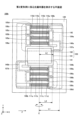
図1は、第1実施形態に係る可動装置である光偏向器を例示する平面図である。図2は、図1のA-A切断線に沿う断面図である。
First Embodiment
Fig. 1 is a plan view illustrating an optical deflector which is a movable device according to the first embodiment, Fig. 2 is a cross-sectional view taken along line AA in Fig. 1.
図1に示すように、光偏向器100は、可動部103と、アクチュエータ104a及び104bと、支持体120と、を有する。光偏向器100は、可動部103を回動軸E周りに回動させることで、可動部103に入射する光を偏向する可動装置の一例である。
As shown in FIG. 1, the
可動部103は、平面視が略矩形状のミラー部101と、ミラー部101の基体の+Z側の面上に形成されたミラー反射面102等を有する。ミラー部101は、例えば、シリコン層から構成される。ミラー部101は、酸化材や無機材料、有機材料で構成されてもよいし、複数の材料又は同じ材料の複数層で構成されてもよい。
The
ミラー反射面102は、例えば、アルミニウム、金、銀等を含む金属薄膜やその多層膜で構成される。また、ミラー部101の基体の-Z側の面にミラー部補強用のリブ構造が形成されていてもよい。リブ構造は、例えば、シリコン支持層及び酸化シリコン層から構成され、可動によって生じるミラー部101及びミラー反射面102の変形歪を抑制する。
The
可動部103は、アクチュエータ104a及び104bにより回動可能な状態で支持されている。本実施形態では、ミラー部101及び可動部103は、平面視が略矩形状の形状に形成されているが、これに限定されるものではなく、円形状、楕円形状、又は多角形状、その他如何なる形状に形成されていてもよい。
The
アクチュエータ104a及び104bの各々は、可動部103を回動軸E周りに回動可能な駆動部の一例である。アクチュエータ104a及び104bの各々の一端は可動部103に接続されており、他端は支持体120に接続されている。
Each of the
アクチュエータ104aは、複数の梁部105a、105b、105c及び105dと、第1の接続部108a、108b及び108cと、第2の接続部107aと、を有する。
The
複数の梁部105a、105b、105c及び105dは、隣り合う梁部同士が第1の接続部108a、108b及び108cにより折り返すように接続されることで、ミアンダ構造をなしている。
The
梁部105aには第2の圧電部材110aが設けられており、梁部105bには第1の圧電部材110bが設けられており、梁部105cには第2の圧電部材110cが設けられており、梁部105dには第1の圧電部材110dが設けられている。
The second
アクチュエータ104aは、第2の接続部107aを介して回動軸Eと交差する方向で可動部103に接続されている。第2の接続部107aは、梁部105aと、可動部103と、を接続している。第2の接続部107aが可動部103に接続する位置は、回動軸Eに沿った方向における可動部103の中央よりもアクチュエータ104a側である。
The
アクチュエータ104bは、複数の梁部106a、106b、106c及び106dと、第1の接続部109a、109b及び109cと、第2の接続部107bと、を有する。
The
複数の梁部106a、106b、106c及び106dは、隣り合う梁部同士が第1の接続部109a、109b及び109cにより折り返すように接続されることで、折り返し構造(ミアンダ構造)をなしている。
The
梁部106aには第1の圧電部材111aが設けられており、梁部106bには第2の圧電部材111bが設けられており、梁部106cには第1の圧電部材111cが設けられており、梁部106dには第2の圧電部材111dが設けられている。
The first
アクチュエータ104bは、第2の接続部107bを介して回動軸Eと交差する方向で可動部103に接続されている。第2の接続部107bは、梁部106aと、可動部103とを接続している。第2の接続部107bが可動部103に接続する位置は、回動軸Eに沿った方向における可動部103の中央よりもアクチュエータ104b側である。
The
第1の圧電部材110b、110d、111a及び111cは、第1の駆動電圧が印加されることにより変形し、第2の圧電部材110a、110c、111b及び111dは、第1の駆動電圧とは逆位相となる第2の駆動電圧が印加されることにより変形する。第1及び第2の圧電部材の各々が変形することで、各梁部に反りが発生する。
The first
各梁部の反りにより隣り合う梁部が異なる方向に撓み、撓みが累積されることにより、アクチュエータ104a及び104bの各々に接続されている可動部103が回動軸E周りに往復回動する。
The warping of each beam causes adjacent beams to bend in different directions, and the bending accumulates, causing the
可動部103の回動軸E周りの共振モードに合わせた駆動周波数で第1の駆動電圧及び第2の駆動電圧が印加されることで、可動部103が共振振動し、低い駆動電圧で大きな回動角度を得ることができる。
By applying a first drive voltage and a second drive voltage at a drive frequency that matches the resonant mode of the
駆動電圧の波形には、正弦波、ノコギリ波、又は三角波等を用いることができる。共振モードに限定されず、非共振モードで可動部103を回動させてもよい。光偏向器100の駆動方式には、例えば静電式、圧電式又は電磁式等の何れの駆動方式が適用されてもよい。
The waveform of the driving voltage may be a sine wave, a sawtooth wave, a triangular wave, or the like. The
これらの中でも、駆動部を効果的に配置でき、光偏向器全体のサイズの大型化を抑制できる点では、圧電式による駆動が好ましい。例えば、静電式による駆動では駆動部の外周に櫛歯電極を配置するため、光偏向器全体のサイズが大きくなりやすい。電磁式による駆動では複数の駆動部それぞれへの配線レイアウトとそれぞれに磁界がかかるような磁石の配置が難しく、光偏向器全体のサイズが大きくなりやすい。 Of these, piezoelectric drive is preferred because it allows the drive units to be positioned effectively and prevents the overall size of the optical deflector from becoming too large. For example, electrostatic drive requires the placement of comb electrodes on the outer periphery of the drive units, which tends to increase the overall size of the optical deflector. With electromagnetic drive, it is difficult to lay out the wiring for each of the multiple drive units and to position magnets so that a magnetic field is applied to each of them, which tends to increase the overall size of the optical deflector.
駆動方式が圧電式である場合には、アクチュエータ104aの断面構造は、例えば、図2のようになる。図2に示すように、アクチュエータ104aは、厚み方向(Z方向)に複数の層からなる。具体的には、アクチュエータ104aにおいて、弾性部となる基部がシリコン層130により形成されている。シリコン層130の厚みは、例えば、20[μm]~60[μm]程度である。シリコン層130により形成された基部は、剛性を有し、半導体プロセス処理に適用可能な材料であればよく、無機材料又は有機材料、金属ガラス等により形成されていてもよい。また、複数の材料を多層化した多層構造であってもよい。
When the driving method is a piezoelectric type, the cross-sectional structure of the
アクチュエータ104aにおいて、シリコン層130の+Z側の面の上に、下部電極131、圧電層132、上部電極133が順に積層されている。下部電極131、圧電層132、及び上部電極133は圧電駆動部を構成している。
In the
下部電極131及び上部電極133は、例えば、金(Au)又は白金(Pt)等により形成されている。圧電層132は、例えば、圧電材料であるPZT(チタン酸ジルコン酸鉛)等により形成されているが、その他の圧電材料であってもよく、種類は問わない。
The
また、圧電駆動部は、圧電層が複数積層され、中間電極を含む構造のものであってもよい。圧電駆動部は、外部制御装置に電気的に接続されており、駆動電圧が印加されることで駆動する。圧電駆動部の+Z側は、酸化シリコン等により形成された不図示の絶縁膜で覆われており、その絶縁膜の+Z側の面の上に電気配線が形成されていてもよい。 The piezoelectric driving unit may also have a structure in which multiple piezoelectric layers are stacked and includes an intermediate electrode. The piezoelectric driving unit is electrically connected to an external control device and is driven by application of a driving voltage. The +Z side of the piezoelectric driving unit is covered with an insulating film (not shown) made of silicon oxide or the like, and electrical wiring may be formed on the +Z side surface of the insulating film.
なお、図2では、アクチュエータ104aの断面構造を例示したが、アクチュエータ104bにおいても同様である。
Note that while Figure 2 illustrates an example of the cross-sectional structure of actuator 104a, the same applies to
アクチュエータ104a及び104bの各々に何らかのセンサが形成されていてもよい。センサは特に限定されないが、例えば、変形に応じて信号を出力する変位検出用センサ(圧電式、ひずみ抵抗式等)や温度センサ等が挙げられる。 Each of the actuators 104a and 104b may be formed with some kind of sensor. The sensor is not particularly limited, but examples include a displacement detection sensor (piezoelectric type, strain resistance type, etc.) that outputs a signal in response to deformation, a temperature sensor, etc.
<可動部、第1の接続部及び第2の接続部の各端部と回動軸との距離>
図1において、距離L1は、第2の接続部107aのうち、回動軸Eと直交する直交方向Fで回動軸Eから最も離れた部分140aと、回動軸Eと、の間の距離を表している。距離L2は、可動部103のうち、直交方向Fで回動軸Eから最も離れた部分141と、回動軸Eと、の間の距離を表している。距離L3は、第1の接続部108bのうち、直交方向Fで回動軸Eから最も離れた部分142と、回動軸Eと、の間の距離を表している。図1に示すように、本実施形態では、距離L1は距離L2よりも長い。なお、距離L2と距離L3は等しいため、図1では距離L3を括弧書きで表示している。
<Distance between each end of the movable portion, the first connecting portion, and the second connecting portion and the rotation axis>
In FIG. 1, distance L1 represents the distance between the rotation axis E and a
光偏向器は、一般に回動軸に直交する方向に加速度が作用すると、回動軸周りに可動部が大きく回動することにより、可動部の初期角度がずれる場合がある。初期角度とは、可動部が回動していない時の可動部の傾き角度をいう。また、上記の加速度には、例えば光偏向器に作用する重力加速度や、光偏向器が自動車やロボットアーム等の移動体に搭載された場合に移動体の加速に応じて光偏向器に作用する加速度等が挙げられる。 When an optical deflector is subjected to acceleration in a direction perpendicular to the rotation axis, the movable part generally rotates significantly around the rotation axis, which can cause the initial angle of the movable part to shift. The initial angle refers to the inclination angle of the movable part when it is not rotating. Examples of the acceleration include the gravitational acceleration acting on the optical deflector, and the acceleration acting on the optical deflector in response to the acceleration of a moving body when the optical deflector is mounted on a moving body such as an automobile or robot arm.
図3は、加速度が作用した場合に生じる可動部の初期角度のずれの一例を示す図であり、図1の光偏向器100における可動部103を-Y側から視た図である。なお、図3では、光偏向器100における可動部103以外の構成部の図示が省略されている。
Figure 3 shows an example of the deviation in the initial angle of the movable part that occurs when acceleration is applied, and is a view of the
図3において、可動部103の初期角度は、角度基準A0に対して角度θ傾いている。角度基準A0は、例えば、可動部103の初期角度が理想的な状態である場合における可動部103のミラー反射面102に対応する。光偏向器100に+X方向への加速度が作用すると、可動部103は角度基準A0に対して初期角度が角度θずれた状態になる。
In FIG. 3, the initial angle of the
初期角度が角度θずれた状態で可動部103が回動すると、可動部103のミラー反射面102に入射して光偏向器100により偏向される光の偏向方向が、角度θに対応して所望の方向からずれる。
When the
角度θと距離L1との間には、次式で表される関係がある。従って、距離L1が長くなるほど角度θが抑制される。
θ∝1/L12
There is a relationship between the angle θ and the distance L1 expressed by the following formula: Therefore, the longer the distance L1, the more the angle θ is suppressed.
θ∝1/ L12
<光偏向器100の作用効果>
以上説明したように、本実施形態に係る光偏向器100(可動装置)は、可動部103と、可動部103を回動軸E周りに回動可能なアクチュエータ104a(駆動部)と、を備える。アクチュエータ104aは、複数の梁部105a、105b、105c及び105dと、隣り合う梁部を接続する第1の接続部108a、108b及び108cと、第2の接続部107aと、を有する。
<Functions and Effects of the
As described above, the optical deflector 100 (movable device) according to this embodiment includes the
第2の接続部107aのうち、回動軸Eと直交する直交方向Fで回動軸Eから最も離れた部分140aと、回動軸Eと、の間の距離L1は、可動部103のうち、直交方向Fで回動軸Eから最も離れた部分141と、回動軸Eと、の間の距離L2よりも長い。この構成により、角度基準A0に対する初期角度のずれである角度θを抑制できる。
The distance L1 between the rotation axis E and the
一方、距離L1を長くすることにより可動部103の面積が大きくなると、共振周波数の低下や駆動感度の低下等を招く懸念がある。なお、駆動感度とは、単位駆動電圧当たりの回動角度をいう。
On the other hand, if the area of the
本実施形態では、距離L1を距離L2よりも長くすることにより、可動部103の面積が大きくなることを防ぎ、距離L1を長くすることに伴う共振周波数の低下や駆動感度の低下等を回避しつつ、角度θを抑制できる。
In this embodiment, by making the distance L1 longer than the distance L2, the area of the
また本実施形態では、アクチュエータ104aは、第2の接続部107aを介して回動軸Eと交差する方向で可動部103に接続されている。これにより、距離L1を距離L2よりも長くする場合に、第2の接続部107aを配置しやすくなる。
In addition, in this embodiment, the
また本実施形態では、第2の接続部107aが可動部103に接続する位置は、回動軸Eに沿った方向において可動部103の中央よりもアクチュエータ104a側である。これにより、距離L1を距離L2よりも長くする場合に、第2の接続部107aを配置しやすくなる。
In addition, in this embodiment, the position where the
なお、本実施形態では、距離L2と距離L3が等しい構成を例示したが、距離L1が距離L2よりも長ければ、距離L3の長さは任意でよい。但し、距離L2と距離L3を等しくすると、アクチュエータ104a及び104bと可動部103の構成を簡略化できるため、より好ましい。
In this embodiment, a configuration in which distance L2 and distance L3 are equal is exemplified, but the length of distance L3 may be arbitrary as long as distance L1 is longer than distance L2. However, making distance L2 and distance L3 equal is more preferable because it simplifies the configuration of actuators 104a and 104b and
また本実施形態では、直交方向Fにおける可動部103の端部を含む可動部103の端面が回動軸Eと略平行である構成を例示したが、これに限定されるものではない。可動部103の端面が回動軸Eに交差する構成であっても、距離L1を距離L2より長くすることで、上記と同様の作用効果が得られる。
In addition, in this embodiment, a configuration has been exemplified in which the end face of the
また、アクチュエータ104aの作用効果について説明したが、アクチュエータ104bにおいても同様である。つまりアクチュエータ104bにおいて、第2の接続部107bのうち、直交方向Fで回動軸Eから最も離れた部分140bと、回動軸Eと、の間の距離L1は、可動部103のうち、直交方向Fで回動軸Eから最も離れた部分141と、回動軸Eと、の間の距離L2よりも長い。この構成によっても、上記と同様の作用効果が得られる。換言すると、第2の接続部107a又は107bの少なくとも一方における距離L1を、距離L2よりも長くすることにより、上記の作用効果を得ることができる。
The effects of the
また、直交方向Fにおける部分140aと、回動軸Eと、の間の距離が、直交方向Fにおける部分140bと、回動軸Eと、の間の距離と等しい場合を例示したが、これに限定されず、両者は異なっていてもよい。両者が異なる場合には、部分140aと部分140bのうち、回動軸Eから離れている方と、回動軸Eと、の間の距離が距離L1に該当する。この距離L1が上記の条件を満たすことで、上記と同様の作用効果を得ることができる。
In addition, the example given above shows that the distance between
<変形例>
次に、第1実施形態の変形例について説明する。なお、上述した実施形態と同一の構成部には同一の符号を付し、重複する説明を適宜省略する。
<Modification>
Next, a modified example of the first embodiment will be described. Note that the same components as those in the above-described embodiment are given the same reference numerals, and duplicated descriptions will be omitted as appropriate.
図4は、第1変形例に係る光偏向器100aを例示する平面図である。図4に示すように、本変形例では、距離L1は距離L3よりも長い。この構成によっても、角度基準A0に対する初期角度のずれである角度θを抑制できる。また、可動部103の面積の増大を防ぐことにより、距離L1を長くすることに伴う共振周波数の低下や駆動感度の低下等を回避できる。
Figure 4 is a plan view illustrating an
なお、距離L1が距離L3よりも長ければ、距離L2の長さは任意でよい。但し、距離L1、L2及びL3が次の(1)式の関係を満たすようにすると、アクチュエータ104a及び104bのばね定数を小さくできるため、駆動感度の向上や回動角度の増大等の点で有利となる。
L1>L3>L2 ・・・ (1)
Note that the length of distance L2 may be arbitrary as long as distance L1 is longer than distance L3. However, if distances L1, L2, and L3 satisfy the relationship of the following formula (1), the spring constant of actuators 104a and 104b can be reduced, which is advantageous in terms of improving drive sensitivity and increasing the rotation angle.
L1>L3>L2... (1)
次に図5は、第2変形例に係る光偏向器100bを例示する平面図である。図5に示すように、本変形例では、距離L1と、距離L2と、距離L3と、の間で次の(2)式の関係がある。
L1>L2>L3 ・・・ (2)
5 is a plan view illustrating an
L1>L2>L3... (2)
この構成により、アクチュエータ104a及び104bのばね定数を大きくすることができるため、光偏向器100bに衝撃が加わった場合における破壊耐性の向上等の点で有利となる。
This configuration allows the spring constant of the actuators 104a and 104b to be increased, which is advantageous in terms of improving resistance to damage when an impact is applied to the
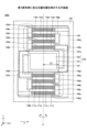
次に図6は、第3変形例に係る光偏向器100cを例示する平面図である。また図7は、第4変形例に係る光偏向器100dを例示する平面図である。
Next, FIG. 6 is a plan view illustrating an
図6に示すように、光偏向器100cでは、第2の接続部107acが可動部103に接続する位置は、回動軸Eに沿った方向における可動部103の中央である。また図7に示すように、光偏向器100dでは、第2の接続部107adが可動部103に接続する位置は、回動軸Eに沿った方向における可動部103の中央よりもアクチュエータ104aとは反対側である。
As shown in FIG. 6, in the
第3及び第4変形例に示すように、第2の接続部107aが可動部103に接続する位置は、回動軸Eに沿った方向で任意であり、何れの位置においても第1実施形態と同様の作用効果を得ることができる。また第3又は第4変形例を、第1変形例と組み合わせることにより、第1変形例と同様の作用効果を得ることができ、また第2変形例と組み合わせることにより、第2変形例と同様の作用効果を得ることができる。
As shown in the third and fourth modified examples, the position at which the
次に図8は、第5変形例に係る光偏向器100eを例示する平面図である。図7に示すように、光偏向器100eは、第2の接続部107ea及び107ebを有する。
Next, FIG. 8 is a plan view illustrating an
第2の接続部107eaは、直交方向Fに沿った幅が+Y側ほど長い形状であって、平面視が略三角形状の形状を有する。第2の接続部107ebは、直交方向Fに沿った幅が-Y側ほど長い形状であって、平面視が略三角形状の形状を有する。 The second connection portion 107ea has a shape in which the width along the orthogonal direction F is longer on the +Y side, and has a generally triangular shape in a planar view. The second connection portion 107eb has a shape in which the width along the orthogonal direction F is longer on the -Y side, and has a generally triangular shape in a planar view.
可動部103と、第2の接続部107ea及び107ebと、の結合形状150は、平面視が平行四辺形状である。この構成により、第2の接続部107ea及び107ebの各々が、可動部103に接続する部分の長さを長くでき、第2の接続部107ea及び107ebの各々と、可動部103と、を安定して接続することができる。
The
なお、第2の接続部107ea及び107ebの形状は、略三角形状に限定されず、任意に選択可能である。そのため、第2の接続部107ea及び107ebの形状を調整することにより、光偏向器100eが有する複数の固有振動モード間の間隔の調整等を行うことができる。
The shape of the second connection parts 107ea and 107eb is not limited to a substantially triangular shape and can be selected arbitrarily. Therefore, by adjusting the shape of the second connection parts 107ea and 107eb, it is possible to adjust the spacing between the multiple natural vibration modes of the
以上に説明した実施形態に係る光偏向器は、光走査システム、光偏向システム、画像投影装置、光書込装置、物体認識装置、レーザヘッドランプ、及びヘッドマウントディスプレイに使用することができる。それぞれについて、以下に順次説明する。 The optical deflector according to the embodiment described above can be used in optical scanning systems, optical deflection systems, image projection devices, optical writing devices, object recognition devices, laser headlamps, and head-mounted displays. Each of these will be described in turn below.
[光走査システム]
まず、実施形態に係る可動装置を適用した光走査システムについて、図9乃至図12に基づいて詳細に説明する。
[Optical scanning system]
First, an optical scanning system to which a movable device according to an embodiment is applied will be described in detail with reference to FIGS.
図9には、光走査システムの一例の概略図が示されている。図9に示すように、光走査システム10は、制御装置11の制御に従って光源装置12から照射された光を可動装置13の有する反射面14により偏向して被走査面15を光走査するシステムである。
Figure 9 shows a schematic diagram of an example of an optical scanning system. As shown in Figure 9, the
光走査システム10は、制御装置11,光源装置12、反射面14を有する可動装置13により構成される。
The
制御装置11は、例えばCPU(Central Processing Unit)及びFPGA(Field-Programmable Gate Array)等を備えた電子回路ユニットである。可動装置13は、例えば反射面14を有し、反射面14を可動可能なMEMS(Micro Electromechanical Systems)デバイスである。光源装置12は、例えばレーザを照射するレーザ装置である。なお、被走査面15は、例えばスクリーンである。
The
制御装置11は、取得した光走査情報に基づいて光源装置12及び可動装置13の制御命令を生成し、制御命令に基づいて光源装置12及び可動装置13に駆動信号を出力する。
The
光源装置12は、入力された駆動信号に基づいて光源の照射を行う。可動装置13は、入力された駆動信号に基づいて反射面14を1軸方向又は2軸方向の少なくとも何れかに可動させる。
The
これにより、例えば、光走査情報の一例である画像情報に基づいた制御装置11の制御によって、可動装置13の反射面14を所定の範囲で2軸方向に往復可動させ、反射面14に入射する光源装置12からの照射光をある1軸周りに偏向して光走査することにより、被走査面15に任意の画像を投影できる。なお、実施形態に係る可動装置の詳細及び制御装置による制御の詳細については後述する。
As a result, for example, by controlling the
次に、光走査システム10一例のハードウェア構成について図10を用いて説明する。図10は、光走査システム10の一例のハードウェア構成図である。図10に示すように、光走査システム10は、制御装置11、光源装置12及び可動装置13を備え、それぞれが電気的に接続されている。このうち、制御装置11は、CPU20、RAM21(Random Access Memory)、ROM22(Read Only Memory)、FPGA23、外部I/F24、光源装置ドライバ25、可動装置ドライバ26を備えている。
Next, the hardware configuration of an example of the
CPU20は、ROM22等の記憶装置からプログラムやデータをRAM21上に読み出し、処理を実行して、制御装置11の全体の制御や機能を実現する演算装置である。
The
RAM21は、プログラムやデータを一時保持する揮発性の記憶装置である。 RAM21 is a volatile storage device that temporarily stores programs and data.
ROM22は、電源を切ってもプログラムやデータを保持することができる不揮発性の記憶装置であり、CPU20が光走査システム10の各機能を制御するために実行する処理用プログラムやデータを記憶している。
The
FPGA23は、CPU20の処理に従って、光源装置ドライバ25及び可動装置ドライバ26に適した制御信号を出力する回路である。
The
外部I/F24は、例えば外部装置やネットワーク等とのインタフェースである。外部装置には、例えば、PC(Personal Computer)等の上位装置、USBメモリ、SDカード、CD、DVD、HDD、SSD等の記憶装置が含まれる。また、ネットワークは、例えば自動車のCAN(Controller Area Network)やLAN(Local Area Network)、インターネット等である。外部I/F24は、外部装置との接続又は通信を可能にする構成であればよく、外部装置ごとに外部I/F24が用意されてもよい。
The external I/
光源装置ドライバ25は、入力された制御信号に従って光源装置12に駆動電圧等の駆動信号を出力する電気回路である。
The light
可動装置ドライバ26は、入力された制御信号に従って可動装置13に駆動電圧等の駆動信号を出力する電気回路である。
The
制御装置11において、CPU20は、外部I/F24を介して外部装置やネットワークから光走査情報を取得する。なお、CPU20が光走査情報を取得することができる構成であればよく、制御装置11内のROM22やFPGA23に光走査情報を格納する構成としてもよいし、制御装置11内に新たにSSD等の記憶装置を設けて、その記憶装置に光走査情報を格納する構成としてもよい。
In the
ここで、光走査情報とは、被走査面15にどのように光走査させるかを示した情報であり、例えば、光走査により画像を表示する場合は、光走査情報は画像データである。また、例えば、光走査により光書込みを行う場合は、光走査情報は書込み順や書込み箇所を示した書込みデータである。他にも、例えば、光走査により物体認識を行う場合は、光走査情報は物体認識用の光を照射するタイミングと照射範囲を示す照射データである。
Here, the optical scanning information is information that indicates how to optically scan the scanned
制御装置11は、CPU20の命令及び図10に示したハードウェア構成によって、次に説明する機能構成を実現することができる。
The
次に、光走査システム10の制御装置11の機能構成について図11を用いて説明する。図11は、光走査システムの制御装置の一例の機能ブロック図である。
Next, the functional configuration of the
図11に示すように、制御装置11は、機能として制御部30と駆動信号出力部31とを有する。
As shown in FIG. 11, the
制御部30は、例えばCPU20、FPGA23等により実現され、外部装置から光走査情報を取得し、光走査情報を制御信号に変換して駆動信号出力部31に出力する。例えば、制御部30は、外部装置等から画像データを光走査情報として取得し、所定の処理により画像データから制御信号を生成して駆動信号出力部31に出力する。駆動信号出力部31は、光源装置ドライバ25、可動装置ドライバ26等により実現され、入力された制御信号に基づいて光源装置12又は可動装置13に駆動信号を出力する。
The
駆動信号は、光源装置12又は可動装置13の駆動を制御するための信号である。例えば、光源装置12においては、光源の照射タイミング及び照射強度を制御する駆動電圧である。また、例えば、可動装置13においては、可動装置13の有する反射面14を可動させるタイミング及び可動範囲を制御する駆動電圧である。
The drive signal is a signal for controlling the drive of the
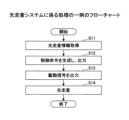
次に光走査システム10が被走査面15を光走査する処理について図12を用いて説明する。図12は光走査システムに係る処理の一例のフローチャートである。
Next, the process of optically scanning the
ステップS11において、制御部30は、外部装置等から光走査情報を取得する。
In step S11, the
ステップS12において、制御部30は、取得した光走査情報から制御信号を生成し、制御信号を駆動信号出力部31に出力する。
In step S12, the
ステップS13において、駆動信号出力部31は、入力された制御信号に基づいて駆動信号を光源装置12及び可動装置13に出力する。
In step S13, the drive
ステップ14において、光源装置12は、入力された駆動信号に基づいて光照射を行う。また、可動装置13は、入力された駆動信号に基づいて反射面14の可動を行う。光源装置12及び可動装置13の駆動により、任意の方向に光が偏向され、光走査される。
In
なお、上記光走査システム10では、1つの制御装置11が光源装置12及び可動装置13を制御する装置及び機能を有しているが、光源装置用の制御装置及び可動装置用の制御装置と、別体に設けてもよい。
In the
また、上記光走査システム10では、一つの制御装置11に光源装置12及び可動装置13の制御部30の機能及び駆動信号出力部31の機能を設けているが、これらの機能は別体として存在していてもよく、例えば制御部30を有した制御装置11とは別に駆動信号出力部31を有した駆動信号出力装置を設ける構成としてもよい。なお、上記光走査システム10のうち、反射面14を有した可動装置13と制御装置11により、光偏向を行う光偏向システムを構成してもよい。
In addition, in the
このように本実施形態に係る可動装置を光走査システムに用いることにより、可動装置に作用する加速度に応じた可動部のずれを抑制し、適切に光を走査させることができる。 In this way, by using the movable device according to this embodiment in an optical scanning system, it is possible to suppress the displacement of the movable part in response to the acceleration acting on the movable device, and to appropriately scan the light.
[画像投影装置]
次に、実施形態に係る可動装置を適用した画像投影装置について、図13及び図14を用いて詳細に説明する。画像投影装置は、光走査により画像を投影する装置であり、例えばヘッドアップディスプレイ装置である。
[Image Projection Device]
Next, an image projection device to which the movable device according to the embodiment is applied will be described in detail with reference to Fig. 13 and Fig. 14. The image projection device is a device that projects an image by optical scanning, and is, for example, a head-up display device.
図13は、画像投影装置の一例であるヘッドアップディスプレイ装置500を搭載した自動車400の概略図である。また、図14はヘッドアップディスプレイ装置500の一例の概略図である。
Figure 13 is a schematic diagram of an
図13に示すように、ヘッドアップディスプレイ装置500は、例えば、自動車400のウインドシールド(フロントガラス401等)の付近に設置される。ヘッドアップディスプレイ装置500から発せられる投射光Lがフロントガラス401で反射され、ユーザーである観察者(運転者402)に向かう。これにより、運転者402は、ヘッドアップディスプレイ装置500によって投影された画像等を虚像として視認することができる。なお、ウインドシールドの内壁面にコンバイナを設置し、コンバイナによって反射する投射光によってユーザーに虚像を視認させる構成にしてもよい。
As shown in FIG. 13, the head-up
図14に示すように、ヘッドアップディスプレイ装置500は、赤色、緑色、青色のレーザ光源501R,501G,501Bからレーザ光が出射される。出射されたレーザ光は、各レーザ光源に対して設けられるコリメートレンズ502,503,504と、2つのダイクロイックミラー505,506と、光量調整部507と、から構成される入射光学系を経た後、反射面14を有する可動装置13にて偏向される。そして、偏向されたレーザ光は、自由曲面ミラー509と、中間スクリーン510と、投射ミラー511とから構成される投射光学系を経て、スクリーンに投影される。なお、上記ヘッドアップディスプレイ装置500では、レーザ光源501R,501G,501B、コリメートレンズ502,503,504、ダイクロイックミラー505,506は、光源ユニット530として光学ハウジングによってユニット化されている。
As shown in FIG. 14, in the head-up
上記ヘッドアップディスプレイ装置500は、中間スクリーン510に表示される中間像を自動車400のフロントガラス401に投射することで、その中間像を運転者402に虚像として視認させる。
The head-up
レーザ光源501R,501G,501Bから発せられる各色レーザ光は、それぞれ、コリメートレンズ502,503,504で略平行光とされ、合成部となる2つのダイクロイックミラー505,506により合成される。合成されたレーザ光は、光量調整部507で光量が調整された後、反射面14を有する可動装置13によって二次元走査される。可動装置13で二次元走査された投射光Lは、自由曲面ミラー509で反射されて歪みを補正された後、中間スクリーン510に集光され、中間像を表示する。中間スクリーン510は、マイクロレンズが二次元配置されたマイクロレンズアレイで構成されており、中間スクリーン510に入射してくる投射光Lをマイクロレンズ単位で拡大する。
The laser light of each color emitted from the
可動装置13は、反射面14を2軸方向に往復可動させ、反射面14に入射する投射光Lを二次元走査する。この可動装置13の駆動制御は、レーザ光源501R,501G,501Bの発光タイミングに同期して行われる。
The
以上、画像投影装置の一例としてのヘッドアップディスプレイ装置500の説明をしたが、画像投影装置は、反射面14を有した可動装置13により光走査を行うことで画像を投影する装置であればよい。例えば、机等に置かれ、表示スクリーン上に画像を投影するプロジェクタや、観測者の頭部等に装着される装着部材に搭載され、装着部材が有する反射透過スクリーンに投影、又は眼球をスクリーンとして画像を投影するヘッドマウントディスプレイ装置等にも、同様に適用することができる。
The above describes the head-up
また、画像投影装置は、車両や装着部材だけでなく、例えば、車両の他に航空機、船舶、移動式ロボット等を含む移動体、あるいは、その場から移動せずにマニピュレータ等の駆動対象を操作する作業ロボットなどの非移動体に搭載されてもよい。自動車400は、移動体の一例であり、車両の一例である。
The image projection device may be mounted not only on a vehicle or a mounting member, but also on a moving body including an aircraft, a ship, a mobile robot, etc. other than a vehicle, or on a non-moving body such as a work robot that operates a drive target such as a manipulator without moving from its location. The
このように本実施形態に係る可動装置を画像投影装置に用いることにより、可動装置に作用する加速度に応じた可動部のずれを抑制し、高品質な画像を投影できる。 In this way, by using the movable device according to this embodiment in an image projection device, it is possible to suppress the displacement of the movable part in response to the acceleration acting on the movable device, and to project a high-quality image.
[物体認識装置]
次に、実施形態に係る可動装置を適用した物体認識装置について、図15及び図16を用いて詳細に説明する。物体認識装置は、対象方向の物体を認識する装置であり、例えばライダ装置である。
[Object Recognition Device]
Next, an object recognition device to which the movable device according to the embodiment is applied will be described in detail with reference to Fig. 15 and Fig. 16. The object recognition device is a device that recognizes an object in a target direction, and is, for example, a LIDAR device.
図15は、物体認識装置の一例であるライダ(LiDAR;Laser Imaging Detection and Ranging)装置を搭載した自動車の概略図である。また、図16はライダ装置の一例の概略図である。 Figure 15 is a schematic diagram of an automobile equipped with a LiDAR (Laser Imaging Detection and Ranging) device, which is an example of an object recognition device. Also, Figure 16 is a schematic diagram of an example of a LiDAR device.
図15に示すように、ライダ装置700は、例えば自動車701に搭載され、対象方向を光走査して、対象方向に存在する被対象物702からの反射光を受光することで、被対象物702を認識する。
As shown in FIG. 15, the
図16に示すように、光源装置12から出射されたレーザ光は、発散光を略平行光とする光学系であるコリメートレンズ703と、平面ミラー704とから構成される入射光学系を経て、反射面14を有する可動装置13で1軸もしくは2軸方向に走査される。そして、投光光学系である投光レンズ705等を経て装置前方の被対象物702に照射される。光源装置12及び可動装置13は、制御装置11により駆動を制御される。被対象物702で反射された反射光は、光検出器709により光検出される。すなわち、反射光は入射光検出受光光学系である集光レンズ706等を経て撮像素子707により受光され、撮像素子707は検出信号を信号処理回路708に出力する。信号処理回路708は、入力された検出信号に2値化やノイズ処理等の所定の処理を行い、結果を測距回路710に出力する。
As shown in FIG. 16, the laser light emitted from the
測距回路710は、光源装置12がレーザ光を発光したタイミングと、光検出器709でレーザ光を受光したタイミングとの時間差、又は受光した撮像素子707の画素ごとの位相差によって、被対象物702の有無を認識し、さらに被対象物702との距離情報を算出する。
The
反射面14を有する可動装置13は多面鏡に比べて破損しづらく、小型であるため、耐久性の高い小型のレーダ装置を提供することができる。このようなライダ装置は、例えば車両、航空機、船舶、ロボット等に取り付けられ、所定範囲を光走査して障害物の有無や障害物までの距離を認識することができる。
The
上記物体認識装置では、一例としてのライダ装置700の説明をしたが、物体認識装置は、反射面14を有した可動装置13を制御装置11で制御することにより光走査を行い、光検出器により反射光を受光することで被対象物702を認識する装置であればよく、上述した実施形態に限定されるものではない。
The above object recognition device has been described as an example of a
例えば、手や顔を光走査して得た距離情報から形状等の物体情報を算出し、記録と参照することで対象物を認識する生体認証や、対象範囲への光走査により侵入物を認識するセキュリティセンサ、光走査により得た距離情報から形状等の物体情報を算出して認識し、3次元データとして出力する3次元スキャナの構成部材などにも同様に適用することができる。 For example, it can be used in biometric authentication, where object information such as shape is calculated from distance information obtained by optically scanning a hand or face, and the target object is recognized by referencing the record; security sensors recognize intruders by optically scanning a target range; and components of 3D scanners that calculate and recognize object information such as shape from distance information obtained by optical scanning, and output it as 3D data.
このように実施形態に係る可動装置を物体認識装置に用いることにより、可動装置に作用する加速度に応じた可動部のずれを抑制し、認識精度が高い物体認識装置を提供できる。 In this way, by using the movable device according to the embodiment in an object recognition device, it is possible to provide an object recognition device with high recognition accuracy by suppressing the displacement of the movable part in response to the acceleration acting on the movable device.
[パッケージング]
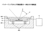
次に、実施形態に係る可動装置のパッケージングについて図17を用いて説明する。図17は、パッケージングされた可動装置の一例の概略図である。
[Packaging]
Next, packaging of the movable device according to the embodiment will be described with reference to Fig. 17. Fig. 17 is a schematic diagram of an example of a packaged movable device.
図17に示すように、可動装置13は、パッケージ部材801の内側に配置される取付部材802に取り付けられ、パッケージ部材801の一部を透過部材803で覆われて、密閉されることでパッケージングされる。さらに、パッケージ内は窒素等の不活性ガスが密封されている。これにより、可動装置13の酸化による劣化が抑制され、さらに温度等の環境の変化に対する耐久性が向上する。
As shown in FIG. 17, the
[計測装置]
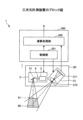
次に、実施形態に係る可動装置13を適用した計測装置について、図18及び図19を用いて詳細に説明する。ここでは、パターン投影法を用いて対象物の三次元計測を行う三次元計測装置を計測装置の一例とする。図18は、三次元計測装置の構成の一例を示すブロック図である。図19は、三次元計測装置により対象物に計測用パターンが投影されている状態を示す図である。
[Measuring equipment]
Next, a measurement device to which the
図18に示すように、三次元計測装置1は、計測情報取得ユニット20と、制御ユニット300と、を有する。
As shown in FIG. 18, the three-
計測情報取得ユニット20は、投影装置2と、カメラ装置21と、を有する。図1に示す投影装置2は、VCSELアレイ(垂直共振器面発光レーザアレイ:Vertical Cavity Surface Emitting LASER)3と、光学系4と、可動装置13と、を有する。VCSELアレイ3を光源とすることにより、発光間隔を細かくでき、且つ集光点を複数形成できる。
The measurement
計測情報取得ユニット20は、制御ユニット300の制御部301の制御に従い、VCSELアレイ3に含まれる複数の発光素子の光を可動装置13により偏向させて計測領域の対象物に投影する。制御部301は、VCSELアレイ3の各発光素子の輝度と点灯タイミングを制御することで、図19に示すように、対象物7を含む計測領域全体に所定の計測用パターンの投影光6を投影する。
The measurement
計測用パターンとして、VCSELアレイ3の発光素子の点灯及び消灯(オン/オフ)を制御することで、白黒のグレイコードパターン等の所定の投影パターンが投影される。図18では、VCSELアレイ3の光をライン状へとするための光学系4が光源部とは独立して設けられているが、光源部に含まれていてもよい。
A predetermined projection pattern such as a black and white gray code pattern is projected as a measurement pattern by controlling the lighting and extinguishing (on/off) of the light emitting elements of the
カメラ装置21は、投影装置2が対象物に投影する投影光6の投影中心41が撮像領域40の略中心となるように固定された位置及び角度で、上述の計測領域を撮像する。
The
カメラ装置21は、受光光学系であるレンズ210、撮像素子211を有する。撮像素子211としては、例えばCCD(Charge Coupled Device)又はCMOS(Complementary Metal Oxide Semiconductor)のイメージセンサ等を用いることができる。カメラ装置21に入射した光は、レンズ210を介して撮像素子211上に結像して光電変換される。撮像素子211で光電変換により生成された画像信号は、制御ユニット300の演算処理部302に供給される。
The
レンズ210には、VCSELアレイ3の発光波長を透過する狭帯域のフィルタを用いてもよい。これにより、計測時の周辺光(蛍光灯などの外乱となる光)の影響を抑え、精度の良い計測を可能とすることができる。なお、レンズ210の前段に狭帯域フィルタを設けてもよい。この場合も、同じ効果を得ることができる。
The
制御ユニット300は、投影装置2によって、計測用パターン光の投影制御及びカメラ装置21による撮像制御等を行い、カメラ装置21が撮像した画像に関する情報に基づいて、計測対象の三次元計測等の演算処理を行う。なお、制御部301は、投影装置2が投影する計測用パターン光を別のパターン光に切り替える制御を行ってもよい。また、制御部301は、演算処理部302が三次元座標の算出に用いるキャリブレーション情報を出力制御してもよい。
The
制御ユニット300の演算処理部302は、供給された画像に関する情報に基づいて、対象物7の三次元形状に対応する三次元座標、又は、三次元座標に関する情報を算出(計測)する。演算処理部302は、算出された三次元形状を示す三次元形状情報を、制御部301の制御に従ってパーソナルコンピュータ装置等の外部機器に出力してもよい。
The
なお、図18は、制御ユニット300に対して1組の計測情報取得ユニット20が設けられている例であるが、制御ユニット300に対し複数組の計測情報取得ユニット20を設けてもよい。また、図18では計測情報取得ユニット20と制御ユニット300が独立して設けられている例であるが、制御ユニット300の一部又は全てが計測情報取得ユニット20に含まれていてもよい。
Note that FIG. 18 shows an example in which one measurement
このように実施形態に係る可動装置を計測装置に用いることにより、可動装置に作用する加速度に応じた可動部のずれを抑制し、計測精度が高い計測装置を提供できる。 In this way, by using the movable device according to the embodiment in a measuring device, it is possible to provide a measuring device with high measurement accuracy by suppressing the displacement of the movable part in response to the acceleration acting on the movable device.
[ロボット]
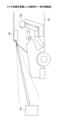
次に、実施形態に係る可動装置13を適用したロボットについて、図20を用いて詳細に説明する。図20は、ロボット70の多関節を有するロボットアームを示す図である。
[robot]
Next, a robot to which the
図20において、多関節アームであるロボットアーム72は、対象物7をピッキングするためのハンド部71を備え、ハンド部71の直近に三次元計測装置1が設けられている。ロボットアーム72は、それぞれ屈曲可能な複数の関節を備え、ハンド部71の位置及び姿勢を、制御に従い変更する。
In FIG. 20, a
三次元計測装置1は、光の投影方向がハンド部71の向く方向に一致するように設けられ、ハンド部71のピッキング対象を計測の対象物7として計測する。
The three-
ロボット70は、ロボットアーム72に設けられた三次元計測装置1により、ピッキングの対象物7を近距離から計測することができる。このため、カメラ装置等により、ピッキングの対象物7を遠方からの計測する場合と比較して、計測精度の向上を図ることができる。例えば、工場の様々な組立てライン等におけるFA分野においては、部品の検査及び認識等のために、ロボットアーム72を備えるロボット70が利用される。ロボット70に三次元計測装置1を設けることにより、部品の検査及び認識を精度よく行うことができる。
The
また、測距用の撮像画像に無効領域が存在する場合、画像信号及び三次元形状に基づき、補完データの取得が可能となる位置及び姿勢を示す位置姿勢情報を、ロボットアーム72にフィードバックする。これにより、ロボットアーム72の制御を簡易に行うことができ、データ補完した計測結果より、より高精度な部品検査又は認識等を行うことができる。
In addition, if an invalid area exists in the captured image for distance measurement, position and orientation information indicating the position and orientation at which complementary data can be acquired based on the image signal and three-dimensional shape is fed back to the
また、計測器と計測対象の位置及び姿勢の関係が相対的に変更すればよい。このため、三次元計測装置1をロボットアーム72に設けているが、計測対象をロボットアーム72に設け、位置及び姿勢を変更しても良い。
Furthermore, the position and orientation of the measuring instrument and the measurement target may be changed relatively. For this reason, the three-
三次元計測装置1をロボットアーム72に搭載して、被計測物体を三次元計測する場合、三次元計測装置1から200mmの間隔が好適である。そのため、パターン光(ライン光)の出射光線の広がり角が21度以上必要となるが、本実施形態ではこれを達成する。
When the three-
このように実施形態に係る可動装置をロボットに用いることにより、可動装置に作用する加速度に応じた可動部のずれを抑制し、位置及び姿勢を高精度に制御可能なロボットを提供できる。 By using the movable device according to the embodiment in a robot in this way, it is possible to provide a robot whose position and orientation can be controlled with high precision by suppressing the displacement of the movable part in response to the acceleration acting on the movable device.
以上、好ましい実施形態等について詳説したが、上述した実施形態等に制限されることはなく、特許請求の範囲に記載された範囲を逸脱することなく、上述した実施形態等に種々の変形及び置換を加えることができる。 Although the preferred embodiments have been described above in detail, the present invention is not limited to the above-described embodiments, and various modifications and substitutions can be made to the above-described embodiments without departing from the scope of the claims.
例えば、上記の各実施形態では可動部がミラー部を有しているが、可動部はミラー部の代わりに回折格子、フォトダイオード、ヒータ(例えば、SiNを用いたヒータ)、光源(例えば、面発光型レーザ)等を有してもよい。 For example, in each of the above embodiments, the movable part has a mirror part, but the movable part may have a diffraction grating, a photodiode, a heater (e.g., a heater using SiN), a light source (e.g., a surface-emitting laser), etc. instead of the mirror part.
1 三次元計測装置
2 投影装置
3 VCSELアレイ
4 光学系
6 投影光
7 対象物
70 ロボット
71 ハンド部
72 ロボットアーム
10 光走査システム
11 制御装置
12、12b 光源装置
13 可動装置
14 反射面
15 被走査面
25 光源装置ドライバ
26 可動装置ドライバ
30 制御部
31 駆動信号出力部
100 光偏向器(可動装置の一例)
101 ミラー部
102 ミラー反射面
103 可動部
104a、104b アクチュエータ(駆動部の一例)
105a、105b、105c、105d 梁部
106a、106b、106c、106d 梁部
107a、107b 第2の接続部
108a、108b、108c 第1の接続部
109a、109b、109c 第1の接続部
110b、110d、111a、111c 第1の圧電部材
110a、110c、111b、111d 第2の圧電部材
130 シリコン層
131 下部電極
132 圧電層
133 上部電極
140a、140b 第2の接続部のうち、直交方向で回動軸から最も離れた部分
141 可動部のうち、直交方向で回動軸から最も離れた部分
142 第1の接続部のうち、直交方向で回動軸から最も離れた部分
150 結合形状
400 自動車(移動体の一例、車両の一例)
E 回動軸
F 直交方向
L1、L2、L3 距離
θ 角度
101: Mirror portion 102: Mirror reflecting surface 103:
105a, 105b, 105c, 105d
E Rotation axis F Orthogonal directions L1, L2, L3 Distance θ Angle
Claims (17)
前記可動部を回動軸周りに回動可能な駆動部と、を備え、
前記駆動部は、
複数の梁部と、
隣り合う前記梁部を接続する第1の接続部と、
前記梁部と前記可動部を接続する第2の接続部と、を有し、
前記第2の接続部のうち、前記回動軸と直交する直交方向で前記回動軸から最も離れた部分と、前記回動軸と、の間の距離は、前記可動部のうち、前記直交方向で前記回動軸から最も離れた部分と、前記回動軸と、の間の距離よりも長く、
前記第2の接続部が前記可動部に接続する位置は、前記回動軸に沿った方向において前記可動部の中央よりも前記駆動部とは反対側であることを特徴とする可動装置。 A movable part;
A drive unit capable of rotating the movable unit around a rotation axis,
The drive unit is
A plurality of beams;
a first connection portion that connects adjacent beam portions;
a second connection portion that connects the beam portion and the movable portion,
a distance between the rotation axis and a portion of the second connection portion that is farthest from the rotation axis in a direction perpendicular to the rotation axis is longer than a distance between the rotation axis and a portion of the movable portion that is farthest from the rotation axis in the direction perpendicular to the rotation axis;
A movable device, characterized in that the position where the second connection portion is connected to the movable portion is on the opposite side to the drive portion from the center of the movable portion in the direction along the rotation axis .
前記可動部を回動軸周りに回動可能な駆動部と、を備え、A drive unit capable of rotating the movable unit around a rotation axis,
前記駆動部は、The drive unit is
複数の梁部と、A plurality of beams;
隣り合う前記梁部を接続する第1の接続部と、a first connection portion that connects adjacent beam portions;
前記梁部と前記可動部を接続する第2の接続部と、を有し、a second connection portion that connects the beam portion and the movable portion,
前記第2の接続部のうち、前記回動軸と直交する直交方向で前記回動軸から最も離れた部分と、前記回動軸と、の間の距離は、前記可動部のうち、前記直交方向で前記回動軸から最も離れた部分と、前記回動軸と、の間の距離よりも長く、a distance between the rotation axis and a portion of the second connection portion that is farthest from the rotation axis in a direction perpendicular to the rotation axis is longer than a distance between the rotation axis and a portion of the movable portion that is farthest from the rotation axis in the direction perpendicular to the rotation axis;
前記可動部と、前記第2の接続部と、の結合形状は、平面視が平行四辺形状であることを特徴とする可動装置。A movable device, characterized in that the combined shape of the movable portion and the second connection portion is a parallelogram in a plan view.
前記可動部を回動軸周りに回動可能な駆動部と、を備え、
前記駆動部は、
複数の梁部と、
隣り合う前記梁部を接続する第1の接続部と、
前記梁部と前記可動部とを接続する第2の接続部と、を有し、
前記第2の接続部のうち、前記回動軸と直交する直交方向で前記回動軸から最も離れた部分と、前記回動軸と、の間の距離は、前記第1の接続部のうち、前記直交方向で前記回動軸から最も離れた部分と、前記回動軸と、の間の距離よりも長く、
前記第2の接続部が前記可動部に接続する位置は、前記回動軸に沿った方向において前記可動部の中央よりも前記駆動部とは反対側であることを特徴とする可動装置。 A movable part;
A drive unit capable of rotating the movable unit around a rotation axis,
The drive unit is
A plurality of beams;
a first connection portion that connects adjacent beam portions;
a second connection portion that connects the beam portion and the movable portion,
a distance between the rotation axis and a portion of the second connection portion that is farthest from the rotation axis in a direction perpendicular to the rotation axis is longer than a distance between the rotation axis and a portion of the first connection portion that is farthest from the rotation axis in the direction perpendicular to the rotation axis;
A movable device, characterized in that the position where the second connection portion is connected to the movable portion is on the opposite side to the drive portion from the center of the movable portion in the direction along the rotation axis .
前記可動部を回動軸周りに回動可能な駆動部と、を備え、A drive unit capable of rotating the movable unit around a rotation axis,
前記駆動部は、The drive unit is
複数の梁部と、A plurality of beams;
隣り合う前記梁部を接続する第1の接続部と、a first connection portion that connects adjacent beam portions;
前記梁部と前記可動部とを接続する第2の接続部と、を有し、a second connection portion that connects the beam portion and the movable portion,
前記第2の接続部のうち、前記回動軸と直交する直交方向で前記回動軸から最も離れた部分と、前記回動軸と、の間の距離は、前記第1の接続部のうち、前記直交方向で前記回動軸から最も離れた部分と、前記回動軸と、の間の距離よりも長く、a distance between the rotation axis and a portion of the second connection portion that is farthest from the rotation axis in a direction perpendicular to the rotation axis is longer than a distance between the rotation axis and a portion of the first connection portion that is farthest from the rotation axis in the direction perpendicular to the rotation axis;
前記可動部と、前記第2の接続部と、の結合形状は、平面視が平行四辺形状であることを特徴とする可動装置。A movable device, characterized in that the combined shape of the movable portion and the second connection portion is a parallelogram in a plan view.
L1>L3>L2 ・・・ (1) The movable device according to any one of claims 1 to 5, characterized in that the distance between the rotation axis and a portion of the second connection portion farthest from the rotation axis in the orthogonal direction is L1, the distance between the rotation axis and a portion of the movable portion farthest from the rotation axis in the orthogonal direction is L2, and the distance between the rotation axis and a portion of the first connection portion farthest from the rotation axis in the orthogonal direction is L3, satisfies the condition of the following equation (1).
L1>L3>L2... (1)
L1>L2>L3 ・・・ (2) The movable device according to any one of claims 1 to 5, characterized in that the distance between the rotation axis and a portion of the second connection portion that is farthest from the rotation axis in the orthogonal direction is L1, the distance between the rotation axis and a portion of the movable portion that is farthest from the rotation axis in the orthogonal direction is L2, and the distance between the rotation axis and a portion of the first connection portion that is farthest from the rotation axis in the orthogonal direction is L3, satisfies the condition of the following equation (2).
L1>L2>L3... (2)
光を発する光源と、
を備え、
前記光源から発せられた光を偏向して投影することを特徴とする画像投影装置。 A movable device according to any one of claims 1 to 9;
A light source that emits light;
Equipped with
An image projection device which projects light emitted from the light source by deflecting the light.
複数の前記光源は、異なる波長の光を発するものであって、
複数の前記光源から発した複数の前記光を合成する合成部を更に備え、
前記合成部において合成された光を偏向して投影することを特徴とする請求項10に記載の画像投影装置。 The light source is provided in plurality,
The plurality of light sources emit light of different wavelengths,
A combining unit that combines the plurality of light beams emitted from the plurality of light sources is further provided,
11. The image projection device according to claim 10, wherein the light combined in the combining unit is deflected and projected.
光を発する光源と、を備え、
前記光源から発せられた光を偏向し、前記光が物体に照射され、前記物体において反射された反射光を検出することにより、前記物体を認識することを特徴とする物体認識装置。 A movable device according to any one of claims 1 to 9;
A light source that emits light,
An object recognition device comprising: a light source that is deflected, the light is irradiated onto an object, and the reflected light reflected by the object is detected, thereby recognizing the object.
光を発する光源と、
を備え、
前記光源から発せられた光を偏向し、前記光が物体に照射され、前記物体において反射された反射光に基づき、前記物体の形状を計測することを特徴とする計測装置。 A movable device according to any one of claims 1 to 9;
A light source that emits light;
Equipped with
A measuring apparatus comprising: a light source that is deflected; an object is irradiated with the light; and a shape of the object is measured based on the light reflected by the object.
Priority Applications (2)
| Application Number | Priority Date | Filing Date | Title |
|---|---|---|---|
| JP2021067475A JP7651925B2 (en) | 2021-04-13 | 2021-04-13 | Movable devices, image projection devices, head-up displays, object recognition devices, measuring devices, robots, moving bodies and vehicles |
| JP2025036168A JP2025096722A (en) | 2021-04-13 | 2025-03-07 | Movable devices, image projection devices, head-up displays, object recognition devices, measuring devices, robots, moving bodies and vehicles |
Applications Claiming Priority (1)
| Application Number | Priority Date | Filing Date | Title |
|---|---|---|---|
| JP2021067475A JP7651925B2 (en) | 2021-04-13 | 2021-04-13 | Movable devices, image projection devices, head-up displays, object recognition devices, measuring devices, robots, moving bodies and vehicles |
Related Child Applications (1)
| Application Number | Title | Priority Date | Filing Date |
|---|---|---|---|
| JP2025036168A Division JP2025096722A (en) | 2021-04-13 | 2025-03-07 | Movable devices, image projection devices, head-up displays, object recognition devices, measuring devices, robots, moving bodies and vehicles |
Publications (2)
| Publication Number | Publication Date |
|---|---|
| JP2022162594A JP2022162594A (en) | 2022-10-25 |
| JP7651925B2 true JP7651925B2 (en) | 2025-03-27 |
Family
ID=83724618
Family Applications (2)
| Application Number | Title | Priority Date | Filing Date |
|---|---|---|---|
| JP2021067475A Active JP7651925B2 (en) | 2021-04-13 | 2021-04-13 | Movable devices, image projection devices, head-up displays, object recognition devices, measuring devices, robots, moving bodies and vehicles |
| JP2025036168A Pending JP2025096722A (en) | 2021-04-13 | 2025-03-07 | Movable devices, image projection devices, head-up displays, object recognition devices, measuring devices, robots, moving bodies and vehicles |
Family Applications After (1)
| Application Number | Title | Priority Date | Filing Date |
|---|---|---|---|
| JP2025036168A Pending JP2025096722A (en) | 2021-04-13 | 2025-03-07 | Movable devices, image projection devices, head-up displays, object recognition devices, measuring devices, robots, moving bodies and vehicles |
Country Status (1)
| Country | Link |
|---|---|
| JP (2) | JP7651925B2 (en) |
Citations (6)
| Publication number | Priority date | Publication date | Assignee | Title |
|---|---|---|---|---|
| WO2013168386A1 (en) | 2012-05-07 | 2013-11-14 | パナソニック株式会社 | Optical reflection element |
| JP2016102812A (en) | 2014-11-27 | 2016-06-02 | 株式会社リコー | Light deflector, image display device, and object device |
| WO2017104613A1 (en) | 2015-12-18 | 2017-06-22 | 株式会社リコー | Light deflection apparatus, head-up display apparatus, optical writing unit, image forming apparatus, and object recognition apparatus |
| JP2018022004A (en) | 2016-08-02 | 2018-02-08 | 株式会社リコー | Optical deflector, image display system |
| JP2018155989A (en) | 2017-03-21 | 2018-10-04 | 株式会社リコー | Optical scan system, image projection device, and object recognition device |
| JP2020003531A (en) | 2018-06-25 | 2020-01-09 | 株式会社リコー | Movable device, image projection device, head-up display, laser headlamp, head-mounted display, object recognition device, and vehicle |
Family Cites Families (5)
| Publication number | Priority date | Publication date | Assignee | Title |
|---|---|---|---|---|
| JP2009223113A (en) * | 2008-03-18 | 2009-10-01 | Panasonic Corp | Optical reflection element and image projection apparatus using the same |
| JP2010122413A (en) * | 2008-11-19 | 2010-06-03 | Panasonic Corp | Optical reflection element |
| DE102011089514B4 (en) * | 2011-12-22 | 2022-09-01 | Robert Bosch Gmbh | Micro mirror and 2 mirror system |
| JP6959525B2 (en) * | 2017-12-21 | 2021-11-02 | ミツミ電機株式会社 | Optical scanning device |
| JP7365042B2 (en) * | 2019-10-18 | 2023-10-19 | フェムトディプロイメンツ株式会社 | Electromagnetic signal analysis device and electromagnetic signal analysis program |
-
2021
- 2021-04-13 JP JP2021067475A patent/JP7651925B2/en active Active
-
2025
- 2025-03-07 JP JP2025036168A patent/JP2025096722A/en active Pending
Patent Citations (6)
| Publication number | Priority date | Publication date | Assignee | Title |
|---|---|---|---|---|
| WO2013168386A1 (en) | 2012-05-07 | 2013-11-14 | パナソニック株式会社 | Optical reflection element |
| JP2016102812A (en) | 2014-11-27 | 2016-06-02 | 株式会社リコー | Light deflector, image display device, and object device |
| WO2017104613A1 (en) | 2015-12-18 | 2017-06-22 | 株式会社リコー | Light deflection apparatus, head-up display apparatus, optical writing unit, image forming apparatus, and object recognition apparatus |
| JP2018022004A (en) | 2016-08-02 | 2018-02-08 | 株式会社リコー | Optical deflector, image display system |
| JP2018155989A (en) | 2017-03-21 | 2018-10-04 | 株式会社リコー | Optical scan system, image projection device, and object recognition device |
| JP2020003531A (en) | 2018-06-25 | 2020-01-09 | 株式会社リコー | Movable device, image projection device, head-up display, laser headlamp, head-mounted display, object recognition device, and vehicle |
Also Published As
| Publication number | Publication date |
|---|---|
| JP2025096722A (en) | 2025-06-27 |
| JP2022162594A (en) | 2022-10-25 |
Similar Documents
| Publication | Publication Date | Title |
|---|---|---|
| JP7167500B2 (en) | Mobile devices, image projection devices, head-up displays, laser headlamps, head-mounted displays, object recognition devices, and vehicles | |
| JP7459580B2 (en) | Mobile devices, image projection devices, head-up displays, laser headlamps, head-mounted displays, object recognition devices, and moving objects | |
| JP7451930B2 (en) | Optical deflectors, deflection devices, distance measuring devices, image projection devices, and vehicles | |
| US20210058592A1 (en) | Light deflector, optical scanning system, image projection device, image forming apparatus, and lidar device | |
| JP7501762B2 (en) | Movable device, image projection device, head-up display, laser headlamp, head-mounted display, object recognition device, and vehicle | |
| US12235440B2 (en) | Movable apparatus | |
| US12554123B2 (en) | Movable device, image projection apparatus, laser headlamp, head-mounted display, distance measurement device, and mobile object | |
| JP2020101587A (en) | Movable device, distance measuring device, image projection device, and vehicle | |
| JP2021067722A (en) | Movable device, image projection device, head-up display, laser head lamp, head-mounted display, object recognition device, and vehicle | |
| US20220299759A1 (en) | Light deflector, image projection apparatus, and distance-measuring apparatus | |
| JP7651925B2 (en) | Movable devices, image projection devices, head-up displays, object recognition devices, measuring devices, robots, moving bodies and vehicles | |
| US11971537B2 (en) | Light deflection device, distance measurement device, and mobile body | |
| JP7338403B2 (en) | Optical deflectors, image projection devices, head-up displays, laser headlamps, head-mounted displays, object recognition devices, and vehicles | |
| US20220155582A1 (en) | Operating device, light deflector, light deflecting device, distance measurement apparatus, image projection apparatus, and mobile object | |
| JP7764772B2 (en) | Movable devices, distance measuring devices, measuring devices, robots, electronic devices, molding devices, image projection devices, head-up displays, laser headlamps, head-mounted displays, object recognition devices, vehicles and moving objects | |
| JP7501309B2 (en) | Optical devices, measuring devices, robots, electronic devices and modeling devices | |
| US12379587B2 (en) | Light deflector, image projection apparatus, laser headlamp, head-mounted display, distance measurement apparatus, and mobile object | |
| JP7608909B2 (en) | Movable device, deflection device, object recognition device, image projection device, and moving body | |
| JP7456294B2 (en) | Movable devices, deflection devices, distance measuring devices, image projection devices, and vehicles | |
| JP7790052B2 (en) | Operating device, optical deflector, optical deflection device, distance measuring device, image projection device, and moving object | |
| JP2025020044A (en) | Movable devices, projection devices, head-up displays, laser headlamps, head-mounted displays, object recognition devices and moving objects, eye tracking devices | |
| JP2018005201A (en) | Actuator device and actuator system | |
| JP2023140219A (en) | Mobile devices, light polarizing elements, image projection devices, head-up displays, laser headlamps, head-mounted displays, object recognition devices, and moving objects | |
| JP2021148670A (en) | Measurement method, optical device, measurement device, moving body, robot, electronic instrument, and shape formation device | |
| JP2025132247A (en) | Movable device, projection device, moving body, head-mounted display, head-up display, laser headlamp, object recognition device, and position detection device |
Legal Events
| Date | Code | Title | Description |
|---|---|---|---|
| A621 | Written request for application examination |
Free format text: JAPANESE INTERMEDIATE CODE: A621 Effective date: 20240222 |
|
| A131 | Notification of reasons for refusal |
Free format text: JAPANESE INTERMEDIATE CODE: A131 Effective date: 20250107 |
|
| A521 | Request for written amendment filed |
Free format text: JAPANESE INTERMEDIATE CODE: A523 Effective date: 20250131 |
|
| TRDD | Decision of grant or rejection written | ||
| A01 | Written decision to grant a patent or to grant a registration (utility model) |
Free format text: JAPANESE INTERMEDIATE CODE: A01 Effective date: 20250212 |
|
| A61 | First payment of annual fees (during grant procedure) |
Free format text: JAPANESE INTERMEDIATE CODE: A61 Effective date: 20250225 |
|
| R150 | Certificate of patent or registration of utility model |
Ref document number: 7651925 Country of ref document: JP Free format text: JAPANESE INTERMEDIATE CODE: R150 |