JP7635757B2 - Combustion air flow rate control method, metal plate manufacturing method, and continuous heating furnace - Google Patents
Combustion air flow rate control method, metal plate manufacturing method, and continuous heating furnace Download PDFInfo
- Publication number
- JP7635757B2 JP7635757B2 JP2022112326A JP2022112326A JP7635757B2 JP 7635757 B2 JP7635757 B2 JP 7635757B2 JP 2022112326 A JP2022112326 A JP 2022112326A JP 2022112326 A JP2022112326 A JP 2022112326A JP 7635757 B2 JP7635757 B2 JP 7635757B2
- Authority
- JP
- Japan
- Prior art keywords
- combustion
- air ratio
- flow rate
- door
- combustion zone
- Prior art date
- Legal status (The legal status is an assumption and is not a legal conclusion. Google has not performed a legal analysis and makes no representation as to the accuracy of the status listed.)
- Active
Links
Images


Landscapes
- Waste-Gas Treatment And Other Accessory Devices For Furnaces (AREA)
- Furnace Details (AREA)
- Regulation And Control Of Combustion (AREA)
- Tunnel Furnaces (AREA)
Description
本発明は、連続式加熱炉、及びそれを用いた金属板の製造方法に係る技術に関し、特に連続式加熱炉の燃焼帯を加熱するバーナーの燃焼空気流量の調整に関する技術である。 The present invention relates to technology related to a continuous heating furnace and a method for manufacturing metal sheets using the same, and in particular to technology related to adjusting the combustion air flow rate of a burner that heats the combustion zone of a continuous heating furnace.
連続式加熱炉は、被加熱体の搬送方向に沿って複数のゾーンに区画されることで、複数の燃焼帯を有し、被加熱体は各燃焼帯で順番に加熱されることで目標とする加熱温度に加熱される。各燃焼帯にはそれぞれバーナーが設けられ、そのバーナーによって、各燃焼帯での加熱処理が実行される。 A continuous heating furnace has multiple combustion zones, which are divided into zones along the transport direction of the material to be heated, and the material to be heated is heated to the target heating temperature by being heated in each combustion zone in turn. Each combustion zone is provided with a burner, and the heat treatment in each combustion zone is carried out by the burner.
そして、連続式加熱炉では、各燃焼帯において、バーナーの最適な燃焼を維持するために、バーナーへの燃料ガス流量と燃焼空気流量の比率を用いて、バーナーに供給する燃料や空気の流量制御を行う。 In a continuous heating furnace, the flow rates of fuel and air supplied to the burners are controlled using the ratio of fuel gas flow rate to combustion air flow rate to the burners in each combustion zone to maintain optimal combustion in the burners.
ここで、バーナーで燃料が完全燃焼するために必要な空気流量(理論空気量)に対し、実際の空気流量の比率(空気比)を低くすることは、熱効率の向上や、製造する金属板のスケール生成の抑制に対し有利に働く。更に、燃料である混合ガスの理論空気量の変動や、被加熱体であるスラブの出し入れを行う装入扉や抽出扉の開閉による炉内への侵入空気の影響を考慮する場合がある。この場合、炉内の酸素濃度や一酸化炭素濃度を各燃焼帯で測定して、各燃焼帯毎に測定結果に基づき燃焼制御を行うことが好ましい。 Here, lowering the ratio of the actual air flow rate (air ratio) to the air flow rate (theoretical air volume) required for complete combustion of the fuel in the burner is advantageous for improving thermal efficiency and suppressing the formation of scale on the metal plates being manufactured. Furthermore, there are cases where consideration is given to fluctuations in the theoretical air volume of the mixed gas that is the fuel, and the influence of air entering the furnace due to the opening and closing of the loading and extraction doors through which the slabs to be heated are loaded and unloaded. In this case, it is preferable to measure the oxygen concentration and carbon monoxide concentration in the furnace in each combustion zone and perform combustion control based on the measurement results for each combustion zone.
ここで、特許文献1には、排ガス損失を十分に低減することが可能な、バーナーへの燃焼空気流量の制御方法について記載されている。特許文献1では、装入扉や抽出扉が開くことにより炉内に侵入する外気の影響に対処する。このために、特許文献1では、炉内の排ガス移流及び滞留を考慮した非定常質量保存式を用いて燃焼帯毎の侵入空気を算出し、燃焼空気の設定流量を設定することが開示されている。
しかし、特許文献1に記載されている方法では、短時間しか扉が開かない状況などの場合であっても、扉が開く度に流入する外気を考慮して炉内の空気比を算出しなければならず、空気比の算出負荷が高まる。更に、扉が開くことによる急激な炉内のガス濃度変化に対し、特許文献1に記載されている方法では、応答性(追随性)に難があるという課題がある。
However, with the method described in
本発明は、上記のような点に着目してなされたもので、空気比の算出負荷の増加を抑えつつ、燃焼空気流量の制御に用いる炉内の空気比を安定した値とすることを目的とする。 The present invention was made with the above points in mind, and aims to stabilize the air ratio in the furnace used to control the combustion air flow rate while suppressing an increase in the load of calculating the air ratio.
課題解決のため、本発明の一態様は、被加熱体の搬送方向に沿って配列する複数の燃焼帯を備える炉体と、各燃焼帯に設置された複数のバーナーとを備える連続式加熱炉における、上記バーナーへ供給される燃焼空気流量の制御方法であって、上記複数の燃焼帯から選択した1又は2以上の燃焼帯である調整対象の燃焼帯に配置されたバーナーへ供給される燃焼空気流量の制御について、上記調整対象の燃焼帯毎に、調整対象の燃焼帯で測定された酸素濃度及び一酸化炭素濃度から、燃焼帯内の空気比を算出する算出工程と、上記燃焼帯内の空気比から、燃焼帯内の空気比を目標空気比となるように上記バーナーの燃焼空気流量を調整する調整工程と、上記炉体が有する上記被加熱体の出し入れ用の扉が開くと判定すると、上記扉が開くと判定してから予め設定した時間経過するまで、上記扉が開く直前に上記算出工程が算出した空気比を、上記調整工程で用いる燃焼帯内の空気比とする空気比設定工程と、を備えることを要旨とする。 In order to solve the problem, one aspect of the present invention is a method for controlling the flow rate of combustion air supplied to burners in a continuous heating furnace having a furnace body with multiple combustion zones arranged along the transport direction of the heated material and multiple burners installed in each combustion zone, and the method includes the following steps for controlling the flow rate of combustion air supplied to burners installed in a combustion zone to be adjusted, which is one or more combustion zones selected from the multiple combustion zones: a calculation step for calculating an air ratio in the combustion zone from the oxygen concentration and carbon monoxide concentration measured in the combustion zone to be adjusted for each combustion zone to be adjusted; an adjustment step for adjusting the combustion air flow rate of the burner from the air ratio in the combustion zone so that the air ratio in the combustion zone becomes a target air ratio; and an air ratio setting step for determining that a door for loading and unloading the heated material of the furnace body is to open, and setting the air ratio calculated in the calculation step immediately before the door opens as the air ratio in the combustion zone to be used in the adjustment step until a preset time has elapsed since it was determined that the door will open.
本発明の態様によれば、一時的に炉内ガス濃度が急激に変化する状況あっても、そのような非定常状態のときに算出した炉内の空気比を用いることをしない。このため、本発明の態様によれば、炉内の空気比の算出負荷の増加を抑えつつ、安定した空気比に基づいて、バーナーへ供給する燃焼空気流量を調整可能となる。この結果、本発明の態様によれば、安定した燃焼制御が実行可能となり、炉内の熱効率の向上や、製造する金属板のスケール生成の抑制に有利に働くことが可能となる。 According to this aspect of the present invention, even if the gas concentration in the furnace changes suddenly temporarily, the air ratio in the furnace calculated during such an unsteady state is not used. Therefore, this aspect of the present invention makes it possible to adjust the combustion air flow rate supplied to the burner based on a stable air ratio while suppressing an increase in the calculation load of the air ratio in the furnace. As a result, this aspect of the present invention makes it possible to execute stable combustion control, which is advantageous in improving the thermal efficiency in the furnace and suppressing the formation of scale on the metal plates being manufactured.
次に、本発明の実施形態について図面を参照して説明する。
(構成)
本実施形態の連続式加熱炉100は、被加熱体がスラブ2の場合を例に説明する。
Next, an embodiment of the present invention will be described with reference to the drawings.
(composition)
The
<炉体1>
本実施形態の連続式加熱炉100は、図1に示すように、加熱するスラブ2の搬送方向(パスライン)に沿って配置された複数の燃焼帯を有する炉体1を有する。炉体1には、スラブ2を装入するための装入扉1Aと、加熱後のスラブ2を抽出するための抽出扉1Bを備える。本実施形態では、上記複数の燃焼帯として、装入側(上流側)から抽出側(下流側)に向けて、予熱帯Z1、加熱帯Z2、及び均熱帯Z3の3種類の燃焼帯が例示されている。図1では、加熱帯Z2及び均熱帯Z3がそれぞれ1つずつの場合を例示しているが、加熱帯Z2及び均熱帯Z3がそれぞれ2以上設けられていても良い。
<
As shown in Fig. 1, the
なお、装入扉1A及び抽出扉1Bには、それぞれ開閉センサ4A、4Bが取り付けられていて、各扉1A、1Bの開閉を検出可能となっている。
本実施形態では、加熱帯Z2及び均熱帯Z3の2つの燃焼帯を、調整対象の燃焼帯とする。予熱帯Z1も調整対象の燃焼帯としても良い。
The
In this embodiment, the two combustion zones, the heating zone Z2 and the soaking zone Z3, are set as the combustion zones to be adjusted. The pre-heating zone Z1 may also be set as the combustion zone to be adjusted.
<バーナー3>
また、各燃焼帯にはそれぞれ、複数のバーナー3が設けられている。図1の例では、各燃焼帯において、バーナー3が、スラブ2の搬送位置よりも上側の上部位置及び下側の下部位置にそれぞれ配置されている。
<Burner 3>
Each combustion zone is provided with a plurality of
<予熱帯Z1>
予熱帯Z1で、スラブ2の予熱を行う。本実施形態では、予熱帯Z1では、予め設定した比率の流量で、燃料ガスと燃焼空気とをバーナー3に供給して、予熱帯Z1での加熱を実行する。符号7は、予熱帯Z1用のバーナー制御部である。この予熱帯Z1のバーナー制御については説明を省略する。
<Pre-tropical zone Z1>
In the preheating zone Z1, the
<加熱帯Z2及び均熱帯Z3>
本実施形態では、予熱帯Z1以外の燃焼帯、つまり加熱帯Z2及び均熱帯Z3で、スラブ2の最適な燃焼を維持する。このために、本実施形態では、バーナー3に供給する燃料ガス流量と燃焼空気流量の比率を用いて、バーナー3に供給する燃料ガスと空気の流量制御を行う。
<Heating zone Z2 and soaking zone Z3>
In this embodiment, optimal combustion of the
本実施形態の加熱帯Z2及び均熱帯Z3にはそれぞれ、図1及び図2に示すように、酸素濃度計、一酸化炭素濃度計、温度計6が設置されている。また、本実施形態の加熱帯Z2及び均熱帯Z3は、図2に示すように、バーナー3用のガス流量計12、空気流量計11、ガス流量調整弁14、及び空気流量調整弁13を備える。
In the heating zone Z2 and the soaking zone Z3 of this embodiment, an oxygen concentration meter, a carbon monoxide concentration meter, and a
酸素濃度計は、炉内の酸素濃度を測定するセンサである。一酸化炭素濃度計は、炉内の一酸化炭素濃度を測定するセンサである。温度計6は、炉内温度を測定するセンサである。また、ガス流量計12は、バーナー3への燃料ガス流量を測定するセンサである。空気流量計11は、バーナー3への燃焼空気流量を測定するセンサである。なお、温度計6で測定した炉内温度は、酸素濃度計で測定した酸素濃度や一酸化炭素濃度計で測定した一酸化炭素濃度の補正に用いられる。また、ガス流量計12で測定した燃料ガス流量と、空気流量計11で測定した燃焼空気流量は、各バーナー3のバーナー空気比の算出に用いられる。
The oxygen concentration meter is a sensor that measures the oxygen concentration in the furnace. The carbon monoxide concentration meter is a sensor that measures the carbon monoxide concentration in the furnace. The
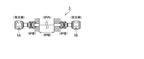
ここで、本実施形態において、加熱帯Z2及び均熱帯Z3にそれぞれ設置される酸素濃度計及び一酸化炭素濃度計は、炉内の複数箇所での酸素濃度及び一酸化炭素濃度を一緒に測定することが可能なレーザー式ガス分析計5であることが好ましい。
本実施形態のレーザー式ガス分析計5は、図3に示すように、レーザーを照射する発光器5Aとレーザーを受ける受光器5Bが燃焼帯(加熱帯Z2及び均熱帯Z3)の炉幅方向で対向する位置に設置されて構成される。そして、レーザー式ガス分析計5は、炉幅方向における、炉内の複数箇所における酸素濃度、及び一酸化炭素濃度の平均値を測定することができる。このようにレーザー式ガス分析計5を設置して、燃焼帯の炉幅方向にレーザーを照射することで、上下方向にレーザーを照射する構成に比べ、レーザーが搬送中のスラブ2に干渉することを抑制することができる。この結果、本構成では、濃度測定の精度を高めることができる。
Here, in this embodiment, the oxygen concentration meter and the carbon monoxide concentration meter installed in the heating zone Z2 and the soaking zone Z3, respectively, are preferably laser-
As shown in Fig. 3, the
なお、レーザー式ガス分析計5にバーナー3の炎が当たると測定精度が悪化する。このため、本実施形態では、バーナー3を炉内の上部及び下部に配置して、各バーナー3の火炎が横方向に向くように配置する。併せて、本実施形態では、その上下のバーナー3の設置位置よりも、レーザー式ガス分析計5の設置位置を、燃焼帯の高さ方向における中央付近(スラブ2の上辺り)に設置している(図1参照)。
Note that if the flame of the
また、加熱帯Z2では、予熱帯Z1から流れてきたガスの濃度を効率よく測定するため、レーザー式ガス分析計5を、予熱帯Z1側(上流側)に近づけて設置することが好ましい。均熱帯Z3では、抽出扉1B付近(下流側)でガスの濃度変化が激しいため、レーザー式ガス分析計5を、炉内ガス濃度が安定している加熱帯Z2側(上流側)に近づけて設置することが好ましい。
In addition, in the heating zone Z2, in order to efficiently measure the concentration of the gas flowing from the preheating zone Z1, it is preferable to install the
<バーナー制御部>
連続式加熱炉100は、加熱帯Z2、均熱帯Z3用のバーナー制御部8X、8Yを備える。加熱帯Z2、均熱帯Z3用のバーナー制御部8X、8Yを総称して記載する場合には、バーナー制御部8と記載する。
バーナー制御部8は、燃焼帯毎に設けられている。なお、複数の燃焼帯Z2、Z3のバーナー制御を一のバーナー制御部で実行しても良いし、各バーナー制御部8の処理の一部を共通の処理部で処理を行うように構成しても良い。
<Burner control unit>
The
A
本開示に係る、加熱帯Z2用のバーナー制御部8Xと均熱帯Z3用のバーナー制御部8Yの処理構成は、同様な構成によって同様な処理が実行される。
ここでは、加熱帯Z2用のバーナー制御部8Xを想定して説明するが、均熱帯Z3用のバーナー制御部8Yも同じ構成となる。
各バーナー制御部8は、図4に示すように、測定データ入力部8A、空気比算出部8B、空気比設定部8C、燃焼空気流量調整部8Dを備える。
The
Here, the description will be given assuming that the
As shown in FIG. 4, each
<測定データ入力部8A>
測定データ入力部8Aは、対象とする燃焼帯Z内の雰囲気ガス濃度を測定するセンサからの検出信号を入力する。具体的には、対象とする燃焼帯Zに設けられた酸素濃度計、一酸化炭素濃度計を構成するレーザー式ガス分析計5、及び温度計6からの検出信号を、予め設定されたサンプリング周期で入力する。
<Measurement
The measurement
<空気比算出部8B>
空気比算出部8Bは、予め設定されたサンプリング周期で、対象とする燃焼帯Zで測定した酸素濃度及び一酸化炭素濃度から、対象とする燃焼帯Zでの炉内の空気比を算出する処理を行う。空気比とは、燃料が完全燃焼するのに理論的に必要な空気量に対し、どれぐらい過剰に空気を投入しているか(空気過剰率)を意味し、(空気流量)/(燃料流量×燃料の理論空気量)で表される。
<Air
The air
ここで、炉内の酸素濃度、一酸化炭素濃度、燃料の理論空気量、理論排ガス量が既知であれば、燃焼帯Z毎の空気比を推定することが可能である。 Here, if the oxygen concentration, carbon monoxide concentration, theoretical air volume of the fuel, and theoretical exhaust gas volume in the furnace are known, it is possible to estimate the air ratio for each combustion zone Z.
本実施形態では、炉内の空気比αの算出に、下記の(1)式及び(2)式からなるモデル式を用いた。

ここで、
O2:炉内の酸素濃度
CO:炉内の一酸化炭素濃度
A0 :理論空気量
G’:実際排ガス量
G0’:理論排ガス量
α’:空気比初期値(=目標空気比)
である。
Where:
O2: Oxygen concentration in the furnace CO: Carbon monoxide concentration in the furnace A0 : Theoretical air volume G': Actual exhaust gas volume G0 ': Theoretical exhaust gas volume α': Initial air ratio (= target air ratio)
It is.
本実施形態では、上式で算出された空気比αが、目標空気比である空気比初期値α’となるように空気流量を調整する。目標空気比(空気比初期値α’)は、例えば1.03である。 In this embodiment, the air flow rate is adjusted so that the air ratio α calculated by the above formula becomes the initial air ratio value α', which is the target air ratio. The target air ratio (initial air ratio value α') is, for example, 1.03.
なお、上記モデル式において、空気流量制御の計算負荷低減のため、理論空気量A0や理論排ガス量G0’を定数として(2)式の処理を省略してもよい。この場合、生じた誤差をフィードバック制御で返す構成とすればよい。 In the above model formula, in order to reduce the calculation load of the air flow rate control, the theoretical air amount A0 and the theoretical exhaust gas amount G0 ' may be set as constants and the processing of formula (2) may be omitted. In this case, the generated error may be returned by feedback control.
また、本実施形態では、酸素濃度計及び一酸化炭素濃度計がレーザー式ガス分析計5で構成される。この場合は、(1)式の酸素濃度O2及び一酸化炭素濃度COは、レーザー式ガス分析計5が測定した複数箇所の酸素濃度及び一酸化炭素濃度の平均値となる。
In this embodiment, the oxygen concentration meter and the carbon monoxide concentration meter are configured with a
<空気比設定部8C>
空気比設定部8Cは、炉体1に設けられたスラブ2の出し入れ用の扉(装入扉1A又は抽出扉1B)が開に変化したと判定すると、次の処理を実行する。すなわち、空気比設定部8Cは、扉が開に変化したと判定してから予め設定した時間経過するまで、扉が開く直前に空気比算出部8Bが算出した空気比を、燃焼空気流量調整部8Dで用いる空気比として選択する。また、それ以外の場合、空気比設定部8Cは、空気比算出部8Bが算出する最新の空気比を、燃焼空気流量調整部8Dで用いる空気比として選択する。
なお、扉が開に変化したと判定してから予め設定した時間経過するまで、空気比算出部8Bの処理を中断しても良い。
<Air
When the air
The processing of the air
すなわち、空気比設定部8Cは、開閉センサ4A、4Bからの信号に基づき、装入扉1A及び抽出扉1Bが開くことを検知する。そして、空気比設定部8Cは、扉が開き始めたと判定すると、例えば、扉が開く直前に空気比算出部8Bが算出した空気比を所定の時間保持する。そして、その所定時間、その保持した空気比を燃焼空気流量調整部8Dに供給する。なお、扉1A、1B毎に開変化時の処理を行う。
また、空気比設定部8Cは、扉が開き始めたと判定してから所定の時間経過する間以外では、連続的に空気比算出部8Bが算出した空気比を、順次、燃焼空気流量調整部8Dに供給する。
That is, the air
In addition, the air
ここで、上記の所定時間は、炉体1の装入扉1A又は抽出扉1Bが開いて炉内に外気が急激に侵入することで、炉内のガス雰囲気が急激に変化してから、許容可能なガス濃度の変化となるまでの時間とする。
なお、空気比を一定に保持する所定時間において、その所定時間の間、扉が開いたままであっても、すぐに扉が閉じた場合であっても構わない。
ただし、所定時間の途中で、一度閉じた扉が開いた場合や、もう一方の扉が開に変化した場合には、最新の扉の開を起点として、所定時間のカウント設定を再度実行する。
所定時間は、例えば10秒~60秒の範囲の時間であり、下記の実施例では30秒とした。
Here, the above-mentioned specified time is the time from when the
During the predetermined time period during which the air ratio is maintained constant, the door may remain open or may be immediately closed.
However, if a door that was once closed opens during the specified time, or if the other door changes to an open state, the count setting of the specified time is executed again, starting from the most recent door opening.
The predetermined time is, for example, in the range of 10 seconds to 60 seconds, and in the following embodiment, it is set to 30 seconds.
ここで、本実施形態では、空気比算出部8Bと空気比設定部8Cの処理は一連の処理として実行される。次に、その一連の処理を行う処理例として、第1の例及び第2の例を示す。
Here, in this embodiment, the processes of the air
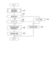
第1の例では、図5に示す処理を、所定サンプリング周期で実行する。
まずステップS10にて、測定した酸素濃度と一酸化炭素濃度とから、上記モデル式で空気比を算出する。本明細書では、算出した空気比を算出空気比と呼ぶ。
In the first example, the process shown in FIG. 5 is executed at a predetermined sampling period.
First, in step S10, the air ratio is calculated from the measured oxygen concentration and carbon monoxide concentration using the above model formula. In this specification, the calculated air ratio is called the calculated air ratio.
次に、ステップS20にて、開閉センサ4A、4Bからの信号に基づき、閉じていた扉が開き始めたか否かを判定し、扉1A、1Bが開いていないと判定した場合には、ステップS30に移行する。一方、扉1A、1Bが開き始めたと判定した場合には、ステップS70に移行する。
Next, in step S20, it is determined whether the closed doors have started to open based on the signals from the opening/
ステップS30では、タイマーがゼロか否かを判定し、タイマーがゼロの場合にはステップS40に移行し、タイマーがゼロより大きければ、ステップS60に移行する。
ここで、タイマーは、初期値がゼロであり、所定時間に対応する所定値がセットされると、時間の経過に伴い数字がゼロに向けてカウントダウンする構成となっている。
In step S30, it is determined whether the timer is zero or not. If the timer is zero, the process proceeds to step S40, and if the timer is greater than zero, the process proceeds to step S60.
Here, the timer has an initial value of zero, and when a predetermined value corresponding to a predetermined time is set, the number counts down toward zero as time passes.
ステップS40では、ステップS10で算出した空気比を記憶部に記憶する。本明細書では、この記憶部に記憶されている空気比を保持空気比と呼ぶ。
続いてステップS50にて、最新の算出空気比を選択し、ステップS10で算出した空気比を出力する。そして、処理を終了する。ここで、空気比を出力するとしているが、選択した空気比の記憶エリアを、燃焼空気流量調整部8Dが参照する構成でも構わない。その他の処理でも同様である。
In step S40, the air ratio calculated in step S10 is stored in a memory unit. In this specification, the air ratio stored in the memory unit is referred to as a retained air ratio.
Next, in step S50, the latest calculated air ratio is selected, and the air ratio calculated in step S10 is output. Then, the process ends. Here, the air ratio is output, but the combustion air flow
ステップS60では、記憶部に記憶されている保持空気比を選択し、その保持空気比を出力する。そして、処理を終了する。
ステップS70では、タイマーに所定値をセットして、ステップS60に移行する。
そして、以上の処理が、繰り返し実行される。
In step S60, the retained air ratio stored in the storage unit is selected, and the retained air ratio is output, and the process ends.
In step S70, a predetermined value is set in the timer, and the process proceeds to step S60.
The above process is then repeatedly executed.
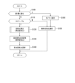
次に、第2の例の処理を説明する。
第2の例では、図6に示す処理を、所定サンプリング周期で実行する。
Next, the process of the second example will be described.
In the second example, the process shown in FIG. 6 is executed at a predetermined sampling period.
まずステップS100にて、開閉センサ4A、4Bからの信号に基づき、閉じていた扉1A、1Bが開き始めたか否かを判定し、扉1A、1Bが開いていないと判定した場合には、ステップS110に移行する。一方、扉が開き始めたと判定した場合には、ステップS160に移行する。
First, in step S100, it is determined whether the
ステップS110では、タイマーがゼロか否かを判定し、タイマーがゼロの場合にはステップS120に移行し、タイマーがゼロより大きければ、ステップS150に移行する。
ここで、タイマーは、初期値がゼロであり、所定時間に対応する所定値がセットされると、時間の経過に伴い数字がゼロに向けてカウントダウンする構成となっている。
In step S110, it is determined whether the timer is zero or not. If the timer is zero, the process proceeds to step S120, and if the timer is greater than zero, the process proceeds to step S150.
Here, the timer has an initial value of zero, and when a predetermined value corresponding to a predetermined time is set, the number counts down toward zero as time passes.
ステップS120では、測定した酸素濃度と一酸化炭素濃度とから、上記モデル式で空気比を算出する。本明細書では、算出した空気比を算出空気比と呼ぶ。 In step S120, the air ratio is calculated from the measured oxygen concentration and carbon monoxide concentration using the above model formula. In this specification, the calculated air ratio is referred to as the calculated air ratio.
次に、ステップS130では、算出した空気比を保持空気比として記憶部に記憶する。続いて、ステップS140にて、最新の算出空気比を選択し、その選択した算出空気比を出力する。そして、処理を終了する。 Next, in step S130, the calculated air ratio is stored in the memory unit as the retained air ratio. Then, in step S140, the most recent calculated air ratio is selected and the selected calculated air ratio is output. Then, the process ends.
ステップS150では、記憶部に記憶されている保持空気比を選択して出力する。そして、処理を終了する。
ステップS160では、タイマーに所定値をセットして、ステップS150に移行する。
以上の処理が、周期的に実行される。
In step S150, the air retention ratio stored in the storage unit is selected and output, and the process ends.
In step S160, a predetermined value is set in the timer, and the process proceeds to step S150.
The above process is executed periodically.
<燃焼空気流量調整部8D>
燃焼空気流量調整部8Dは、空気比設定部8Cから取得した空気比に基づき、対象とする燃焼帯の燃焼空気が目標空気比となるように、対象の燃焼帯Zに設けられたバーナー3への燃焼空気流量を調整する。すなわち、現在の炉内の空気比が目標空気比となる目標燃焼空気流量を求め、その目標燃焼空気流量となるように、燃焼空気用の空気流量調整弁13を調整する。
<Combustion air flow
The combustion air flow
例えば、炉内の空気比が目標空気比よりも予め設定した第1の閾値以上低いと判定したら、バーナー3への燃焼空気流量を増加する。また、炉内の空気比が目標空気比よりも予め設定した第1の閾値以上高いと判定したら、バーナー3への燃焼空気流量を減少する、フィードバック制御を行う。
For example, if it is determined that the air ratio in the furnace is lower than the target air ratio by a preset first threshold or more, the flow rate of combustion air to the
ここで、炉内の酸素濃度(O2)は0.8%以下が好ましいので、炉内の酸素濃度(O2)を0.8%以下とする条件下で、バーナー3への燃焼空気流量を調整することが好ましい。
Here, since the oxygen concentration (O2) in the furnace is preferably 0.8% or less, it is preferable to adjust the combustion air flow rate to
また、本実施形態では、各燃焼帯において、ガス流量計12で測定した燃料ガス流量と、空気流量計11で測定した燃焼空気流量とから、各バーナー3のバーナー空気比を算出する。そして、本実施形態では、炉内の上部に設置されているバーナー3のバーナー空気比と下部に設置されているバーナー3のバーナー空気比とが同じ値になるように調整した。このように上部のバーナー3のバーナー空気比と下部のバーナー3のバーナー空気比とを揃えることで、NOx発生量を低減することができる。
(変形例)
In this embodiment, the burner air ratio of each
(Modification)
上記実施形態は、加熱帯Z2及び均熱帯Z3の両方の燃焼帯を調整対象の燃焼帯Zとし、両燃焼帯Z2、Z3のバーナー制御する。このとき、本実施形態では、扉が開く場合、扉を開く直前の炉内の空気比に基づいて、バーナー3への燃焼空気流量を調整する場合を例示したが、これに限定されない。加熱帯Z2及び均熱帯Z3の一方の燃焼帯についてだけ、扉が開く場合、扉を開く直前の炉内の空気比に基づいて、バーナー3への燃焼空気流量を調整する構成でもよい。
In the above embodiment, both the heating zone Z2 and the soaking zone Z3 are combustion zones Z to be adjusted, and the burners of both combustion zones Z2 and Z3 are controlled. In this embodiment, when the door is opened, the combustion air flow rate to the
また、扉に近い側の燃焼帯だけを、扉が開く場合、扉を開く直前の炉内の空気比に基づいて、バーナー3への燃焼空気流量を調整する構成としても良い。例えば、加熱帯Z2については、装入扉1Aが開く場合、装入扉1Aを開く直前の炉内の空気比に基づいて、バーナー3への燃焼空気流量を調整する構成とする。ただし、抽出扉1Bが開いても、最新の算出空気比を利用してバーナー3への燃焼空気流量を調整する構成とする。また、例えば、均熱帯Z3については、抽出扉1Bが開く場合、抽出扉1Bを開く直前の炉内の空気比に基づいて、バーナー3への燃焼空気流量を調整する構成とする。ただし、装入扉1Aが開いても、最新の算出空気比を利用してバーナー3への燃焼空気流量を調整する構成とする。
Also, only the combustion zone closest to the door may be configured to adjust the combustion air flow rate to
(金属板の製造方法)
本実施形態では、本開示の燃焼空気流量の制御方法を採用した連続式加熱炉100によってスラブ2(厚板)を目標温度に加熱し、加熱したスラブ2を図示しない圧延機によって圧延することによって鋼板を製造する。ここで、金属板として鋼板を例示したが、アルミニウム合金その他の金属板の製造に適用してもよい。
ここで、空気比算出部8Bは、算出工程を構成する。空気比設定部8Cは、空気比設定工程を構成する。燃焼空気流量調整部8Dは、調整工程を構成する。
(Metal plate manufacturing method)
In this embodiment, a slab 2 (thick plate) is heated to a target temperature by a
Here, the air
(動作その他)
本実施形態では、扉が開いて炉内のガス濃度が急激に変化することも考慮にいれて、炉内の空気比を算出しない。このため、本実施形態では、空気比の算出負荷を低減することができると共に、燃焼空気流量の調整に使用する空気比を安定して求めることが出来る。
(Action etc.)
In this embodiment, the air ratio in the furnace is not calculated, taking into consideration the fact that the gas concentration in the furnace changes suddenly when the door is opened. Therefore, in this embodiment, the load of calculating the air ratio can be reduced, and the air ratio used to adjust the combustion air flow rate can be stably obtained.
すなわち、本実施形態では、扉が開いた直後であって炉内雰囲気ガス濃度が急激に変化している非定常状態で算出した空気比は、算出精度が不安定であることを鑑みる。そして、本実施形態では、この不安定な炉内空気比を燃焼空気流量の制御に使用しない。
そして、炉内のガス濃度が安定した状態での、炉内のガス濃度で算出した空気比を使用して、燃焼空気流量を調整するので、本実施形態では、算出精度が良い空気比で燃焼空気流量を調整可能となる。
That is, in this embodiment, the air ratio calculated in the unsteady state immediately after the door is opened, in which the concentration of the atmospheric gas in the furnace is rapidly changing, has unstable calculation accuracy, and therefore this unstable air ratio in the furnace is not used for controlling the combustion air flow rate.
The combustion air flow rate is adjusted using the air ratio calculated from the gas concentration in the furnace when the gas concentration in the furnace is stable, so in this embodiment, it is possible to adjust the combustion air flow rate at an air ratio that is calculated with high accuracy.
また、本実施形態では、レーザー式ガス分析計5を用いて炉内の酸素濃度及び一酸化炭素濃度の平均値を測定する。このため、扉が開いて炉内のガス濃度が局所的に変化した場合であっても、炉内の1箇所の濃度のみを測定する構成に比べて、測定のバラつきを抑制することができ、炉内の酸素濃度及び一酸化炭素濃度を精度よく測定することができる。また、レーザー式ガス分析計5を用いることで、測定の応答性も高くすることができる。
In addition, in this embodiment, the average oxygen concentration and carbon monoxide concentration in the furnace are measured using a
(その他)
本開示は、次の構成も取り得る。
(1) 被加熱体の搬送方向に沿って配列する複数の燃焼帯を備える炉体と、各燃焼帯に設置された複数のバーナーとを備える連続式加熱炉における、上記バーナーへ供給される燃焼空気流量の制御方法であって、
上記複数の燃焼帯から選択した1又は2以上の燃焼帯である調整対象の燃焼帯に配置されたバーナーへ供給される燃焼空気流量の制御について、
上記調整対象の燃焼帯毎に、
調整対象の燃焼帯で測定された酸素濃度及び一酸化炭素濃度から、燃焼帯内の空気比を算出する算出工程と、
上記燃焼帯内の空気比から、燃焼帯内の空気比を目標空気比となるように上記バーナーの燃焼空気流量を調整する調整工程と、
上記炉体が有する上記被加熱体の出し入れ用の扉が開くと判定すると、上記扉が開くと判定してから予め設定した時間経過するまで、上記扉が開く直前に上記算出工程が算出した空気比を、上記調整工程で用いる燃焼帯内の空気比とする空気比設定工程と、
を備える。
(2) 上記複数の燃焼帯は、装入側から抽出側に向けて、予熱帯、1又は2以上の加熱帯、及び1又は2以上の均熱帯がこの順に配置され、
上記調整対象の燃焼帯は、上記加熱帯及び上記均熱帯である。
(3) 上記空気比設定工程の処理は、上記炉体に設けられた扉のうちの開いた扉に一番近い調整対象の燃焼帯でのみ実行する。
(4) 上記算出工程でする酸素濃度及び一酸化炭素濃度は、それぞれ、対象とする燃焼帯内における複数箇所での測定値の平均値とする。
(5) 上記酸素濃度及び一酸化炭素濃度の測定は、レーザー式ガス分析計を用いて実行され、
上記レーザー式ガス分析計は、対象とする燃焼帯内における、複数箇所での酸素濃度及び一酸化炭素濃度を測定する。
(6) 本開示の燃焼空気流量の制御方法で燃焼空気流量の制御が実行される連続式加熱炉によって上記被加熱体であるスラブを加熱する加熱工程を含む、金属板の製造方法。
(8) 被加熱体の搬送方向に沿って配列する複数の燃焼帯を備える炉体と、各燃焼帯に設置された複数のバーナーとを備える連続式加熱炉であって、
上記複数の燃焼帯から選択した1又は2以上の燃焼帯である調整対象の燃焼帯について、
上記調整対象の燃焼帯毎に、
対象とする燃焼帯内の酸素濃度を測定する酸素濃度計と、
対象とする燃焼帯内の一酸化炭素濃度を測定する一酸化炭素濃度計と、
上記酸素濃度計で測定された酸素濃度及び上記一酸化炭素濃度計で測定された一酸化炭素濃度とに基づき、燃焼帯内の空気比を算出する空気比算出部と、
上記算出した燃焼帯内の空気比に基づき、燃焼帯内の空気比を目標空気比となるように上記バーナーの燃焼空気流量を調整する燃焼空気流量調整部と、
上記炉体が有する上記被加熱体の出し入れ用の扉が開くと判定すると、上記扉が開くと判定してから予め設定した時間経過するまで、上記扉が開く直前に上記空気比算出部が算出した空気比を、上記燃焼空気流量調整部で用いる、上記算出した燃焼帯内の空気比とする空気比設定部と、
を備える。
(9) 上記空気比設定部の処理は、上記炉体に設けられた扉のうちの開いた扉に一番近い調整対象の燃焼帯でのみ実行される。
(10) 各調整対象の燃焼帯毎に設置される、上記酸素濃度計及び上記一酸化炭素濃度計は、レーザー式ガス分析計で構成される。
(others)
The present disclosure may also have the following configuration.
(1) A method for controlling a flow rate of combustion air supplied to burners in a continuous heating furnace having a furnace body with a plurality of combustion zones arranged along a transport direction of a heated material and a plurality of burners installed in each combustion zone, comprising the steps of:
Regarding the control of the combustion air flow rate supplied to a burner disposed in a combustion zone to be adjusted, which is one or more combustion zones selected from the plurality of combustion zones,
For each combustion zone to be adjusted,
A calculation step of calculating an air ratio in the combustion zone from the oxygen concentration and the carbon monoxide concentration measured in the combustion zone to be adjusted;
an adjusting step of adjusting a combustion air flow rate of the burner based on the air ratio in the combustion zone so that the air ratio in the combustion zone becomes a target air ratio;
an air ratio setting step of setting the air ratio calculated in the calculation step immediately before the door is opened as the air ratio in the combustion zone used in the adjustment step until a preset time has elapsed since it was determined that the door of the furnace body for loading and unloading the heated object is to be opened;
Equipped with.
(2) The plurality of combustion zones are arranged in the following order from the charging side to the extraction side: a preheating zone, one or more heating zones, and one or more soaking zones;
The combustion zones to be adjusted are the heating zone and the soaking zone.
(3) The air ratio setting process is performed only in the combustion zone to be adjusted that is closest to the open door among the doors provided in the furnace body.
(4) The oxygen concentration and carbon monoxide concentration in the above calculation process are each the average values of measured values at multiple points within the target combustion zone.
(5) The measurement of the oxygen concentration and the carbon monoxide concentration is carried out using a laser gas analyzer;
The laser gas analyzer measures the oxygen and carbon monoxide concentrations at multiple locations within a target combustion zone.
(6) A method for manufacturing a metal plate, comprising a heating step of heating a slab, which is the heated body, in a continuous heating furnace in which the combustion air flow rate is controlled by the combustion air flow rate control method disclosed herein.
(8) A continuous heating furnace having a furnace body with a plurality of combustion zones arranged along the transport direction of the heated material and a plurality of burners installed in each combustion zone,
Regarding the combustion zone to be adjusted, which is one or more combustion zones selected from the plurality of combustion zones,
For each combustion zone to be adjusted,
an oxygen concentration meter for measuring the oxygen concentration in a target combustion zone;
a carbon monoxide concentration meter for measuring the carbon monoxide concentration in a target combustion zone;
an air ratio calculation unit that calculates an air ratio in a combustion zone based on the oxygen concentration measured by the oxygen concentration meter and the carbon monoxide concentration measured by the carbon monoxide concentration meter;
a combustion air flow rate adjusting unit that adjusts a combustion air flow rate of the burner based on the calculated air ratio in the combustion zone so that the air ratio in the combustion zone becomes a target air ratio;
an air ratio setting unit that, when it is determined that a door for inserting and removing the heated object of the furnace body is to be opened, sets the air ratio calculated by the air ratio calculation unit immediately before the door is opened as the air ratio in the combustion zone to be used in the combustion air flow rate adjustment unit until a preset time has elapsed since it was determined that the door is to be opened;
Equipped with.
(9) The processing of the air ratio setting unit is executed only in the combustion zone to be adjusted that is closest to the open door among the doors provided in the furnace body.
(10) The oxygen concentration meter and the carbon monoxide concentration meter installed in each combustion zone to be adjusted are constituted by laser type gas analyzers.
厚板鋼板を製造する設備の連続式加熱炉100について、目標空気比(空気比初期値α’)を1.03とし、炉内の酸素濃度(O2)を0.8%以下とする条件にて、炉内の測定した空気比に基づき、バーナー3への燃焼空気流量を制御して加熱工程を実行してみた。
In a
連続式加熱炉100の構成は、実施形態で説明した構成とし、下記の実施例では、加熱帯Z2及び均熱帯Z3を調整対象の燃焼帯とした。
The
比較例では、扉1A、1Bの開閉に関係無く、炉内で測定した酸素濃度及び一酸化炭素濃度から空気比を所定サンプリング周期で算出し、その算出した空気比に基づきバーナー3への燃焼空気流量を調整した。
In the comparative example, regardless of whether
一方、実施例では、扉が開き始めてから30秒間(所定時間)は、扉が開く直前で算出した空気比を、その30秒間の炉内の空気比(保持空気比)とした以外は、比較例と同じ条件でバーナー3への燃焼空気流量を調整した。
On the other hand, in the embodiment, the combustion air flow rate to
そして、比較例と実施例について、炉内の酸素濃度の標準偏差を求めたところ、比較例では、標準偏差が0.64だった。これに対し、実施例では標準偏差が0.23と小さくなっていた。すなわち、本開示を適用することで、炉内の酸素濃度の標準偏差を大幅に低減することができることが分かった。すなわち、比較例に比べ、炉内の酸素濃度が安定して、より精度良く加熱制御が行われたことが分かった。 The standard deviation of the oxygen concentration in the furnace was calculated for the comparative example and the working example, and the standard deviation was 0.64 for the comparative example. In contrast, the standard deviation for the working example was smaller at 0.23. In other words, it was found that by applying the present disclosure, it is possible to significantly reduce the standard deviation of the oxygen concentration in the furnace. In other words, it was found that the oxygen concentration in the furnace was more stable and heating control was more precisely performed compared to the comparative example.
図7に、炉内の酸素濃度と理論空気量との関係を示す。
図7から分かるように、比較例では、混合ガス成分の変動による理論空気量の変化に適応できなかったが、本開示を適用することで、ガス成分に依存せず最適な燃焼制御を行うことが可能となることが分かった。
FIG. 7 shows the relationship between the oxygen concentration in the furnace and the theoretical amount of air.
As can be seen from Figure 7, the comparative example was unable to adapt to changes in the theoretical air amount due to fluctuations in the mixed gas components, but it was found that by applying the present disclosure, it is possible to perform optimal combustion control regardless of the gas components.
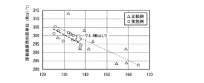
図8に、比較例と実施例の燃料原単位を示す。
図8から分かるように、本開示の燃焼制御技術を用いることで、燃料原単位を削減することができることが分かった。
FIG. 8 shows the fuel consumption rate for the comparative example and the embodiment.
As can be seen from FIG. 8, it was found that the fuel consumption rate can be reduced by using the combustion control technique of the present disclosure.
図9に、比較例と実施例でのスケール性疵による鋼板不合格率変化を示す。
スケール性疵とは、鋼板表面のスケールに起因する疵を指す。
図9から分かるように、本開示を適用することで、鋼板の不合格率を低減することが分かった。
FIG. 9 shows the change in the rejection rate of steel sheets due to scale defects in the comparative example and the example.
The scale defects refer to defects caused by scale on the surface of the steel sheet.
As can be seen from FIG. 9, the application of the present disclosure was found to reduce the rejection rate of steel sheets.
このように、本開示を適用することで、連続式加熱炉100での燃焼制御が改善されて、コストを削減することができると共に、製造される鋼板の不合格率の低減できることが分かった。
In this way, it has been found that application of the present disclosure improves combustion control in the
1 炉体
1A 装入扉
1B 抽出扉
2 スラブ(被加熱体)
3 バーナー
4A、4B 開閉センサ
5 ガス分析計(酸素濃度計、一酸化炭素濃度計)
6 温度計
8、8X、8Y バーナー制御部
8A 測定データ入力部
8B 空気比算出部
8C 空気比設定部
8D 燃焼空気流量調整部
11 空気流量計
12 ガス流量計
13 空気流量調整弁
14 ガス流量調整弁
100 連続式加熱炉
Z 調整対象の燃焼帯
Z1 予熱帯
Z2 加熱帯
Z3 均熱帯
1
3
6
Claims (9)
上記複数の燃焼帯から選択した1又は2以上の燃焼帯である調整対象の燃焼帯に配置されたバーナーへ供給される燃焼空気流量の制御について、
上記調整対象の燃焼帯毎に、
調整対象の燃焼帯で測定された酸素濃度及び一酸化炭素濃度から、燃焼帯内の空気比を算出する算出工程と、
上記燃焼帯内の空気比から、燃焼帯内の空気比を目標空気比となるように上記バーナーの燃焼空気流量を調整する調整工程と、
上記炉体が有する上記被加熱体の出し入れ用の扉が開くと判定すると、上記扉が開くと判定してから予め設定した所定時間が経過するまで、上記扉が開く直前に上記算出工程が算出した空気比を、上記調整工程で用いる燃焼帯内の空気比とする空気比設定工程と、
を備え、
上記空気比設定工程は、上記所定時間の経過前に上記扉が閉じても、該所定時間が経過するまで、上記扉が開く直前に上記算出工程が算出した空気比を、上記調整工程で用いる燃焼帯内の空気比とし、かつ、上記所定時間の経過前に上記扉が閉じて再度扉が開く場合、上記所定時間のカウント開始を上記扉が再度開いたときに設定変更する、
ことを特徴とする、燃焼空気流量の制御方法。 A method for controlling a flow rate of combustion air supplied to burners in a continuous heating furnace having a furnace body with a plurality of combustion zones arranged along a transport direction of a heated material, and a plurality of burners installed in each combustion zone, comprising:
Regarding the control of the combustion air flow rate supplied to a burner disposed in a combustion zone to be adjusted, which is one or more combustion zones selected from the plurality of combustion zones,
For each combustion zone to be adjusted,
A calculation step of calculating an air ratio in the combustion zone from the oxygen concentration and the carbon monoxide concentration measured in the combustion zone to be adjusted;
an adjusting step of adjusting a combustion air flow rate of the burner based on the air ratio in the combustion zone so that the air ratio in the combustion zone becomes a target air ratio;
an air ratio setting step of setting the air ratio calculated in the calculation step immediately before the door is opened as the air ratio in the combustion zone to be used in the adjustment step until a predetermined time has elapsed since it was determined that the door of the furnace body for loading and unloading the heated object is to be opened;
Equipped with
In the air ratio setting step, even if the door is closed before the predetermined time has elapsed, the air ratio calculated in the calculation step immediately before the door is opened is set as the air ratio in the combustion zone to be used in the adjustment step until the predetermined time has elapsed, and if the door is closed and then opened again before the predetermined time has elapsed, the start of counting the predetermined time is changed to a new setting when the door is opened again.
A method for controlling a combustion air flow rate, comprising:
上記調整対象の燃焼帯は、上記加熱帯及び上記均熱帯である、
ことを特徴とする請求項1に記載した燃焼空気流量の制御方法。 The plurality of combustion zones are arranged in the following order from the charging side to the extraction side: a preheating zone, one or more heating zones, and one or more soaking zones;
The combustion zone to be adjusted is the heating zone and the soaking zone.
2. The method for controlling a combustion air flow rate according to claim 1.
ことを特徴とする請求項1~請求項3のいずれか1項に記載した燃焼空気流量の制御方法。 The oxygen concentration and carbon monoxide concentration in the calculation step are each the average values of the measured values at multiple points in the target combustion zone.
A method for controlling a combustion air flow rate according to any one of claims 1 to 3.
上記レーザー式ガス分析計は、対象とする燃焼帯内における、複数箇所での酸素濃度及び一酸化炭素濃度を測定する、
ことを特徴とする請求項4に記載した燃焼空気流量の制御方法。 The measurement of the oxygen concentration and the carbon monoxide concentration is carried out using a laser gas analyzer;
The laser gas analyzer measures the oxygen concentration and carbon monoxide concentration at multiple points within the target combustion zone.
5. A method for controlling a combustion air flow rate according to claim 4.
上記複数の燃焼帯から選択した1又は2以上の燃焼帯である調整対象の燃焼帯について、
上記調整対象の燃焼帯毎に、
対象とする燃焼帯内の酸素濃度を測定する酸素濃度計と、
対象とする燃焼帯内の一酸化炭素濃度を測定する一酸化炭素濃度計と、
上記酸素濃度計で測定された酸素濃度及び上記一酸化炭素濃度計で測定された一酸化炭素濃度とに基づき、燃焼帯内の空気比を算出する空気比算出部と、
上記算出した燃焼帯内の空気比に基づき、燃焼帯内の空気比を目標空気比となるように上記バーナーの燃焼空気流量を調整する燃焼空気流量調整部と、
上記炉体が有する上記被加熱体の出し入れ用の扉が開くと判定すると、上記扉が開くと判定してから予め設定した所定時間が経過するまで、上記扉が開く直前に上記空気比算出部が算出した空気比を、上記燃焼空気流量調整部で用いる、上記算出した燃焼帯内の空気比とする空気比設定部と、
を備え、
上記空気比設定部は、上記所定時間の経過前に上記扉が閉じても、該所定時間が経過するまで、上記扉が開く直前に上記空気比算出部が算出した空気比を、上記燃焼空気流量調整部で用いる燃焼帯内の空気比とし、かつ、上記所定時間の経過前に上記扉が閉じて再度扉が開く場合、上記所定時間のカウント開始を上記扉が再度開いたときに設定変更する、
ことを特徴とする連続式加熱炉。 A continuous heating furnace having a furnace body with a plurality of combustion zones arranged along a transport direction of a heated material, and a plurality of burners installed in each combustion zone,
Regarding the combustion zone to be adjusted, which is one or more combustion zones selected from the plurality of combustion zones,
For each combustion zone to be adjusted,
an oxygen concentration meter for measuring the oxygen concentration in a target combustion zone;
a carbon monoxide concentration meter for measuring the carbon monoxide concentration in a target combustion zone;
an air ratio calculation unit that calculates an air ratio in a combustion zone based on the oxygen concentration measured by the oxygen concentration meter and the carbon monoxide concentration measured by the carbon monoxide concentration meter;
a combustion air flow rate adjusting unit that adjusts a combustion air flow rate of the burner based on the calculated air ratio in the combustion zone so that the air ratio in the combustion zone becomes a target air ratio;
an air ratio setting unit that, when it is determined that a door for inserting and removing the heated object of the furnace body is to be opened, sets the air ratio calculated by the air ratio calculation unit immediately before the door is opened as the air ratio in the combustion zone to be used in the combustion air flow rate adjustment unit until a predetermined time has elapsed since it was determined that the door is to be opened;
Equipped with
Even if the door is closed before the predetermined time has elapsed, the air ratio setting unit sets the air ratio calculated by the air ratio calculation unit immediately before the door is opened as the air ratio in the combustion zone used by the combustion air flow rate adjustment unit until the predetermined time has elapsed, and if the door is closed before the predetermined time has elapsed and then opened again, changes the setting of the start of counting the predetermined time when the door is opened again.
A continuous heating furnace characterized by the above.
ことを特徴とする請求項7に記載した連続式加熱炉。 The processing of the air ratio setting unit is executed only in the combustion zone to be adjusted that is closest to the open door among the doors provided in the furnace body.
8. A continuous heating furnace according to claim 7.
ことを特徴とする請求項7又は請求項8に記載した連続式加熱炉。 The oxygen concentration meter and the carbon monoxide concentration meter installed in each combustion zone to be adjusted are configured as laser gas analyzers.
9. A continuous heating furnace according to claim 7 or 8.
Priority Applications (1)
| Application Number | Priority Date | Filing Date | Title |
|---|---|---|---|
| JP2022112326A JP7635757B2 (en) | 2022-07-13 | 2022-07-13 | Combustion air flow rate control method, metal plate manufacturing method, and continuous heating furnace |
Applications Claiming Priority (1)
| Application Number | Priority Date | Filing Date | Title |
|---|---|---|---|
| JP2022112326A JP7635757B2 (en) | 2022-07-13 | 2022-07-13 | Combustion air flow rate control method, metal plate manufacturing method, and continuous heating furnace |
Publications (2)
| Publication Number | Publication Date |
|---|---|
| JP2024010812A JP2024010812A (en) | 2024-01-25 |
| JP7635757B2 true JP7635757B2 (en) | 2025-02-26 |
Family
ID=89622268
Family Applications (1)
| Application Number | Title | Priority Date | Filing Date |
|---|---|---|---|
| JP2022112326A Active JP7635757B2 (en) | 2022-07-13 | 2022-07-13 | Combustion air flow rate control method, metal plate manufacturing method, and continuous heating furnace |
Country Status (1)
| Country | Link |
|---|---|
| JP (1) | JP7635757B2 (en) |
Citations (5)
| Publication number | Priority date | Publication date | Assignee | Title |
|---|---|---|---|---|
| JP2009133552A (en) | 2007-11-30 | 2009-06-18 | Jfe Steel Corp | Control method of heating furnace dilution fan |
| JP2013095982A (en) | 2011-11-02 | 2013-05-20 | Nippon Steel & Sumitomo Metal Corp | Setting method and control system for furnace temperature of continuous heating furnace, continuous heating furnace, and method for producing metal material |
| JP2016176640A (en) | 2015-03-19 | 2016-10-06 | 三菱日立パワーシステムズ株式会社 | Boiler and method for controlling combustion at boiler |
| JP2019060588A (en) | 2017-09-27 | 2019-04-18 | 株式会社神戸製鋼所 | Method for controlling combustion air flow rate and continuous multiband-type heating furnace |
| JP2020148426A (en) | 2019-03-14 | 2020-09-17 | Jfeスチール株式会社 | Air ratio control method for continuous steel heating furnace and continuous steel heating furnace |
Family Cites Families (3)
| Publication number | Priority date | Publication date | Assignee | Title |
|---|---|---|---|---|
| JPS6051607B2 (en) * | 1979-12-05 | 1985-11-14 | 日本鋼管株式会社 | Combustion control device in heating furnace |
| JPS60159515A (en) * | 1984-01-27 | 1985-08-21 | Hitachi Ltd | Furnace system |
| JPH03102115A (en) * | 1989-09-14 | 1991-04-26 | Toshiba Corp | Excess air ratio setter for combustion control |
-
2022
- 2022-07-13 JP JP2022112326A patent/JP7635757B2/en active Active
Patent Citations (5)
| Publication number | Priority date | Publication date | Assignee | Title |
|---|---|---|---|---|
| JP2009133552A (en) | 2007-11-30 | 2009-06-18 | Jfe Steel Corp | Control method of heating furnace dilution fan |
| JP2013095982A (en) | 2011-11-02 | 2013-05-20 | Nippon Steel & Sumitomo Metal Corp | Setting method and control system for furnace temperature of continuous heating furnace, continuous heating furnace, and method for producing metal material |
| JP2016176640A (en) | 2015-03-19 | 2016-10-06 | 三菱日立パワーシステムズ株式会社 | Boiler and method for controlling combustion at boiler |
| JP2019060588A (en) | 2017-09-27 | 2019-04-18 | 株式会社神戸製鋼所 | Method for controlling combustion air flow rate and continuous multiband-type heating furnace |
| JP2020148426A (en) | 2019-03-14 | 2020-09-17 | Jfeスチール株式会社 | Air ratio control method for continuous steel heating furnace and continuous steel heating furnace |
Also Published As
| Publication number | Publication date |
|---|---|
| JP2024010812A (en) | 2024-01-25 |
Similar Documents
| Publication | Publication Date | Title |
|---|---|---|
| CN101876449B (en) | Method of controlling oxygen air-flowing environment in heating furnace | |
| RU2553783C2 (en) | Method and device of pressure control in continuous annealing furnace | |
| JP5582105B2 (en) | Converter blowing control method | |
| JP2019060588A (en) | Method for controlling combustion air flow rate and continuous multiband-type heating furnace | |
| JP7635757B2 (en) | Combustion air flow rate control method, metal plate manufacturing method, and continuous heating furnace | |
| JP4998655B2 (en) | Combustion control method for continuous heating furnace | |
| JP5314946B2 (en) | Heating furnace controller | |
| US6955730B2 (en) | Method for enhancing the metallurigcal quality of products treated in a furnace | |
| JP2809925B2 (en) | Sheet temperature control method for continuous annealing furnace | |
| CN112016198A (en) | Heating furnace tapping temperature prediction method based on coupling iteration | |
| JPH06274231A (en) | Converter blowing control device and control method | |
| JP2003293030A (en) | Steel sheet cooling method | |
| JP2020094773A (en) | Method for detecting combustion failure in radiant tube burner | |
| KR102608524B1 (en) | Heat treatment methods for metal products | |
| TWI413554B (en) | Furnace pressure control method | |
| JPH09216011A (en) | Cooling control method for hot rolled steel sheet | |
| KR102441323B1 (en) | Heating method and device | |
| JP7207335B2 (en) | Plate temperature control method, heating control device, and metal plate manufacturing method | |
| JPH09316545A (en) | Sheet temperature control method for continuous annealing furnace | |
| JP2005076935A (en) | Billet furnace and operating method thereof | |
| JPH0472022A (en) | Method and device for controlling strip temperature in continuous annealing furnace | |
| JPH0754055A (en) | Steel strip temperature control method in continuous annealing furnace | |
| JPH08199248A (en) | Temperature controller for continuous annealing equipment | |
| JP4815837B2 (en) | Combustion control method for continuous heating furnace | |
| JP2981290B2 (en) | Manufacturing method of galvannealed steel sheet |
Legal Events
| Date | Code | Title | Description |
|---|---|---|---|
| A621 | Written request for application examination |
Free format text: JAPANESE INTERMEDIATE CODE: A621 Effective date: 20240226 |
|
| A977 | Report on retrieval |
Free format text: JAPANESE INTERMEDIATE CODE: A971007 Effective date: 20241011 |
|
| A131 | Notification of reasons for refusal |
Free format text: JAPANESE INTERMEDIATE CODE: A131 Effective date: 20241022 |
|
| A521 | Request for written amendment filed |
Free format text: JAPANESE INTERMEDIATE CODE: A523 Effective date: 20241205 |
|
| TRDD | Decision of grant or rejection written | ||
| A01 | Written decision to grant a patent or to grant a registration (utility model) |
Free format text: JAPANESE INTERMEDIATE CODE: A01 Effective date: 20250114 |
|
| A61 | First payment of annual fees (during grant procedure) |
Free format text: JAPANESE INTERMEDIATE CODE: A61 Effective date: 20250127 |
|
| R150 | Certificate of patent or registration of utility model |
Ref document number: 7635757 Country of ref document: JP Free format text: JAPANESE INTERMEDIATE CODE: R150 |