JP7635591B2 - Underwater Sediment Collection System - Google Patents
Underwater Sediment Collection System Download PDFInfo
- Publication number
- JP7635591B2 JP7635591B2 JP2021048193A JP2021048193A JP7635591B2 JP 7635591 B2 JP7635591 B2 JP 7635591B2 JP 2021048193 A JP2021048193 A JP 2021048193A JP 2021048193 A JP2021048193 A JP 2021048193A JP 7635591 B2 JP7635591 B2 JP 7635591B2
- Authority
- JP
- Japan
- Prior art keywords
- sediment
- container
- underwater
- robot
- robot body
- Prior art date
- Legal status (The legal status is an assumption and is not a legal conclusion. Google has not performed a legal analysis and makes no representation as to the accuracy of the status listed.)
- Active
Links
Images


Landscapes
- Manipulator (AREA)
- Jet Pumps And Other Pumps (AREA)
Description
特許法第30条第2項適用 2020年9月16日に2020年度 オンライン技術開発報告会にて発表Application of Article 30, Paragraph 2 of the Patent Act Announced at the 2020 Online Technology Development Report Meeting on September 16, 2020
本発明は、水中の沈殿物を回収する水中沈殿物回収システムに関する。 The present invention relates to an underwater sediment recovery system that recovers underwater sediments.
従来から、水質汚染を防止するためや、水中に沈殿している有害物を除去するために、水中の沈殿物を回収することが行われている。沈殿物を回収する手段としては、例えば特許文献1に汚泥回収装置および方法が開示されている。特許文献1の汚泥回収装置は、水中を移動可能であると共に水底の汚泥を吸引して回収可能な浚渫装置と、水中を移動可能であると共に浚渫装置により回収された汚泥から水分を除去した回収物を回収物受槽に貯蔵する処理装置と、処理装置に電力や高圧空気などを供給する設備車とを有している。
Conventionally, sediments in water have been collected to prevent water pollution and to remove harmful substances that have settled in the water. For example,
特許文献1の汚泥回収装置では、浚渫装置によって回収された汚泥は、処理装置の回収物受槽に貯槽される。このような構成であると、回収物受槽内に汚泥が回収されたら回収作業を一度中断し、汚泥回収装置(浚渫装置および処理装置)を一度地上に引き上げなくてはならない。そして、回収物受槽を空にした後に汚泥回収装置を水中に戻し、作業を再開する。このため、特許文献1の技術であると作業効率が低く、更なる改良の余地がある。
In the sludge collection device of
本発明は、このような課題に鑑み、途中で装置を地上に戻すことなく沈殿物の回収作業を継続し、作業効率を大幅に向上することが可能な水中沈殿物回収システムを提供することを目的としている。 In view of these problems, the present invention aims to provide an underwater sediment recovery system that allows sediment recovery work to continue without having to return the device to land midway, thereby significantly improving work efficiency.
上記課題を解決するために、本発明にかかる水中沈殿物回収システムの代表的な構成は、水中を走行して沈殿物を回収する沈殿物回収ロボットと、水中に固定設置されるステーションと含む沈殿物回収システムであって、沈殿物回収ロボットは、水中を走行可能なロボット本体と、ロボット本体に装着され水中の沈殿物が回収されるコンテナと、ロボット本体に搭載され沈殿物を含む水を吸引する内蔵ポンプと、コンテナに連通する吸引ノズルと、コンテナに連通する排出ノズルと有し、ステーションは、水中に配置され排出ノズルと連結されるソケットと、ソケットと接続される汲み上げポンプとを有することを特徴とする。 To solve the above problems, a typical configuration of the underwater sediment recovery system according to the present invention is a sediment recovery system including a sediment recovery robot that travels underwater to recover sediment, and a station that is fixedly installed underwater, the sediment recovery robot having a robot body capable of traveling underwater, a container that is attached to the robot body and recovers underwater sediment, a built-in pump that is mounted on the robot body and sucks up water containing sediment, a suction nozzle that communicates with the container, and a discharge nozzle that communicates with the container, and the station having a socket that is placed underwater and connected to the discharge nozzle, and a pump that is connected to the socket.
上記構成によれば、ロボット本体に搭載されたコンテナ内に沈殿物が回収されたら、ロボット本体をステーションに接続して、汲み上げポンプによってコンテナ内の沈殿物のみを地上に移送することができる。したがって、途中で装置(ロボット本体)を地上に戻すことなく沈殿物の回収作業を継続することができるため、作業効率を大幅に向上することが可能となる。 According to the above configuration, once the sediment has been collected in the container mounted on the robot body, the robot body can be connected to the station and the sediment in the container alone can be transported to the ground by a pump. This means that the sediment collection work can be continued without having to return the device (robot body) to the ground midway, making it possible to significantly improve work efficiency.
上記課題を解決するために、本発明にかかる水中沈殿物回収システムの他の構成は、水中を走行して沈殿物を回収する沈殿物回収ロボットと、水中に固定設置されるステーションと含む沈殿物回収システムであって、沈殿物回収ロボットは、水中を走行可能なロボット本体と、ロボット本体に装着され水中の沈殿物が回収されるコンテナと、ロボット本体に搭載され沈殿物を含む水を吸引する内蔵ポンプと、コンテナに連通する吸引ノズルと、コンテナに連通する排出ノズルとを有し、ロボット本体は、排出ノズルのシャッターを開いて回収された沈殿物を移送可能であって、ステーションは、移送された沈殿物を貯留する集積枡と、集積枡から沈殿物を地上に汲み上げる汲み上げポンプとを有することを特徴とする。 To solve the above problems, another configuration of the underwater sediment recovery system according to the present invention is a sediment recovery system including a sediment recovery robot that travels underwater to recover sediment, and a station that is fixedly installed underwater. The sediment recovery robot has a robot body that can travel underwater, a container that is attached to the robot body and recovers underwater sediment, a built-in pump that is mounted on the robot body and sucks up water containing sediment, a suction nozzle that communicates with the container, and a discharge nozzle that communicates with the container. The robot body can transfer the recovered sediment by opening the shutter of the discharge nozzle. The station has a collection basin that stores the transferred sediment, and a pump that pumps the sediment from the collection basin to the ground.
かかる構成によっても、途中で装置(ロボット本体)を地上に戻すことなく沈殿物の回収作業を継続することができるため、作業効率を大幅に向上することが可能となる。特に、バッファとしての集積枡を介して地上に汲み上げることから、ロボット本体から沈殿物を排出する作業と地上で沈殿物を処理する作業とを無関係なタイミングで行うことができるため、作業効率を大幅に向上することが可能となる。 Even with this configuration, sediment collection work can be continued without returning the device (robot body) to the ground midway, making it possible to significantly improve work efficiency. In particular, because the sediment is pumped up to the ground via a collection basin that acts as a buffer, the work of discharging the sediment from the robot body and the work of processing the sediment on the ground can be performed at independent times, making it possible to significantly improve work efficiency.
本発明によれば、途中で装置を地上に戻すことなく沈殿物の回収作業を継続し、作業効率を大幅に向上することが可能な水中沈殿物回収システムを提供することができる。 The present invention provides an underwater sediment recovery system that allows sediment recovery work to continue without returning the device to land midway, greatly improving work efficiency.
以下に添付図面を参照しながら、本発明の好適な実施形態について詳細に説明する。かかる実施形態に示す寸法、材料、その他具体的な数値などは、発明の理解を容易とするための例示に過ぎず、特に断る場合を除き、本発明を限定するものではない。なお、本明細書及び図面において、実質的に同一の機能、構成を有する要素については、同一の符号を付することにより重複説明を省略し、本発明に直接関係のない要素は図示を省略する。 The preferred embodiment of the present invention will be described in detail below with reference to the attached drawings. The dimensions, materials, and other specific values shown in the embodiment are merely examples to facilitate understanding of the invention, and do not limit the present invention unless otherwise specified. In this specification and drawings, elements having substantially the same functions and configurations are given the same reference numerals to avoid duplicated explanations, and elements not directly related to the present invention are not illustrated.
(第1実施形態)
図1は、第1実施形態にかかる水中沈殿物回収システムによって沈殿物を回収する原子力発電所建屋10の概略図である。なお、第1実施形態では沈殿物を回収する施設として原子力発電所建屋10を例示したが、これに限定するものではない。水中に沈殿物が堆積している施設であれば、他の施設であっても第1実施形態の水中沈殿物回収システムを好適に用いることが可能である。
First Embodiment
1 is a schematic diagram of a nuclear
図1に示すように、原子力発電所建屋10は、地上4階、地下2階建ての建物である。1Fは地上への出入り口であり、最地下のB2Fに汚染水が貯蔵されている。この汚染水の放射性物質を吸着するために、B2Fには袋に吸着材(例えばゼオライト等)を詰めた土嚢12が設置されている。土嚢12は長期の設置により放射線で繊維が崩壊して破れ、内容物である吸着材が散逸して沈殿物となる。第1実施形態では、水中に沈殿した吸着材を沈殿物として回収する。
As shown in FIG. 1, the nuclear
原子力発電所建屋10のB2Fには水中沈殿物回収ロボット(以下、回収ロボット100と称する)が配置される。回収ロボット100は、4Fに設置されているクレーン14によってB2Fに搬入される。
An underwater sediment recovery robot (hereinafter referred to as recovery robot 100) is placed on B2F of the nuclear
回収ロボット100はB2Fに到着するとフック16から外れて水中を自走する。回収ロボット100にはフロートケーブル102が接続されて、電源が供給されると共に、カメラの画像データや各種センサーの信号が不図示の制御装置に送信される。
When the
図2は回収ロボット100の前方斜視図である。図2に示すように、第1実施形態の回収ロボット100は主に、ロボット本体110、および沈殿物が回収されるコンテナ150を含んで構成され、水中を走行して沈殿物を回収する。ロボット本体110は下部にクローラ112を有し、設備(原子力発電所建屋10のB2F)の床面に沿って水中を走行可能である。ロボット本体110には、沈殿物が回収されるコンテナ150が装着されている。
Figure 2 is a front perspective view of the
ロボット本体110の前方には、沈殿物を吸引するための吸引ノズル160が配置されている。吸引ノズル160は、コンテナ150に連通している。これにより、ロボット本体110に搭載された内蔵ポンプ120が、コンテナ150を通じて吸引ノズル160から間接的に沈殿物を含んだ水を吸引する。
A
図3は回収ロボット100の後方斜視図である。ロボット本体110の後方には、コンテナ150と連通する排出ノズル170が備えられている。一方、水中にはステーション200が固定設置されている。ステーション200は汲み上げポンプ210とソケット220を備えている。汲み上げポンプ210はソケット220と接続されている。また後述するようにソケット220は排出ノズル170と連結される。
Figure 3 is a rear perspective view of the
図1に示すように、コンテナ150内の沈殿物は、内蔵ポンプ120によってコンテナ150に回収され、汲み上げポンプ210と地上ポンプ240によって吸い上げホース230を通じて原子力発電所建屋10の地上1Fに引き上げられる。そして、引き上げられた沈殿物は所定の容器250に回収されると共に、沈殿物と分離された水は戻り管260によってB2Fに戻される。沈殿物が回収された容器250は放射線漏れを防ぐ遮蔽容器270に収納して、所定の格納庫に移送する。
As shown in FIG. 1, the sediment in the
ただし、上述した地上ポンプ240は、汲み上げポンプ210を補助するために設置しているだけであり、必ずしも設ける必要はない。例えば、汲み上げポンプ210の揚程が十分であれば、地上ポンプ240を不要とすることができる。
However, the above-mentioned
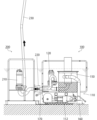
図4は、第1実施形態にかかる水中沈殿物回収システムの詳細を説明する図である。回収ロボット100によって回収された沈殿物を地上に移送する際には、図4に示すように、回収ロボット100を後ろ向きに走行させて、排出ノズル170をステーション200のソケット220に連結する。これにより、コンテナ150の内部に回収された沈殿物が汲み上げポンプ210によって吸引されて地上に移送される。
Figure 4 is a diagram illustrating the details of the underwater sediment recovery system according to the first embodiment. When the sediment recovered by the
上記説明した第1実施形態の水中沈殿物回収システムによれば、ロボット本体110に搭載されたコンテナ150内に沈殿物が回収されたら、ロボット本体110をステーション200に接続して、汲み上げポンプ210によってコンテナ150内の沈殿物のみを地上に移送することができる。ロボット本体110はいちど水中に搬入したら、作業が完了するまで地上に戻すことなく沈殿物の回収作業を継続することができる。したがって、作業効率を大幅に向上することが可能となる。
According to the underwater sediment recovery system of the first embodiment described above, once sediment has been recovered in the
(第2実施形態)
図5は、第2実施形態にかかる水中沈殿物回収システムによって沈殿物を回収する原子炉建屋10の概略図である。図6は、第2実施形態にかかる水中沈殿物回収システムの詳細を説明する図である。なお、第1実施形態と共通の構成要素については、同一の符号を付すことにより説明を省略する。
Second Embodiment
Fig. 5 is a schematic diagram of a
図5に示すように、原子力発電所建屋10のB2F、すなわち汚染水が貯蔵されているフロアに配置されたステーション200には、集積桝280が設けられている。
As shown in FIG. 5, the
図6に示すように、ロボット本体110は、後方に排出ノズル170(図4参照)が配置されておらず、これに代えて下方に移送ノズル190が備えられている。移送ノズル190はコンテナ150に連通して下方に開口していて、途中にシャッター180を備えている。回収ロボット100が内蔵ポンプ120によって吸引している間はシャッター180は閉じられている。シャッター180を開くと、コンテナ150に回収された沈殿物を集積桝280に移送することができる。沈殿物は水よりも重いため、コンテナ150から集積桝280へとゆるやかに移動する。
As shown in FIG. 6, the
そして、ステーション200は、汲み上げポンプ210を用いて、集積桝280に堆積された沈殿物Zを地上に汲み上げる。汲み上げられた沈殿物は、回収管230を通じて地上に移送される。地上1Fにおける沈殿物の処理については上記と同様である。
Then,
上記説明したように、第2実施形態の水中沈殿物回収システムにおいても、コンテナ150に回収された沈殿物のみを地上に移送することができ、ロボット本体110は作業が完了するまで地上に戻すことなく作業を継続することができる。したがって第1実施形態と同様に、作業効率を大幅に向上することが可能となる。
As described above, in the underwater sediment recovery system of the second embodiment, only the sediment recovered in the
図7は、第2実施形態にかかる水中沈殿物回収システムの他の例を説明する図である。図7(a)に示す例では、集積桝280の回収ロボット100と反対側の縁(ステーション200側の縁)を囲うコの字状の囲い282を設けている。図7(b)に示す例では、集積桝280の上面の開口の一部を覆う蓋284を設けている。かかる構成によれば、沈殿物を集積桝に流し込む際の沈殿物の拡散を好適に防ぐことができる。
Figure 7 is a diagram illustrating another example of the underwater sediment recovery system according to the second embodiment. In the example shown in Figure 7(a), a
なお、囲い282の高さは、必ずしも汚染水の水面W(図6参照)よりも高い必要はなく、沈殿物の拡散を防ぐことが可能な程度であればよい。また蓋284は、集積桝280の上面の開口の全面ではなく、開口の一部を覆う大きさとする。これは、集積桝280の上面の開口の全面を覆うと、集積桝280への沈殿物の流し込みや、集積桝280からの沈殿物の汲み上げができなくなってしまうためである。
The height of the
(第3実施形態)
上述の第2実施形態では、汚染水が貯蔵されているフロアに配置されたステーション200に設けられている集積桝280、すなわち既設の集積桝280を用いる構成を例示したが、これに限定するものではない。既設の集積桝280が設けられてない場合には、仮設の集積桝を作業現場に搬入して据付し、かかる仮設の集積桝を用いる構成によっても上記と同様の効果を得ることが可能である。仮設の集積桝を用いる場合には、ポンプの排出力を利用して沈殿物を集積桝に移送してもよいし、重力を利用して沈殿物を集積桝に移送してもよい。
Third Embodiment
In the above-described second embodiment, a configuration is exemplified in which the
図8は、第3実施形態にかかる水中沈殿物回収システムの詳細を説明する図である。なお、第3実施形態では、仮設の集積桝380を用いる場合を想定している。仮設の集積桝380は、端的に表現すれば箱であり、フロア床面に載置される。図8(a)および(b)では、集積桝380の上面の開口が蓋382によって覆われている。そして蓋の四隅には、吊り降ろし用金具390が設けられている。これにより、吊り降ろし用金具390にケーブル102を取り付けてクレーン14(図1参照)によって集積桝380を地下に搬入することができる。
Figure 8 is a diagram for explaining the details of the underwater sediment recovery system according to the third embodiment. In the third embodiment, it is assumed that a
図8(a)に示す例では、蓋382には、汲み上げポンプ210に連結している管212を挿通するための挿通孔384が形成されている。また集積桝380には、排出ノズル170と連結されるソケット386が設けられている。
In the example shown in FIG. 8(a), the
かかる構成では、回収ロボット100によって回収された沈殿物を地上に移送する際には、回収ロボット100を後ろ向きに走行させて、排出ノズル170を集積桝380のソケット386に連結する。これにより、コンテナ150の内部に回収された沈殿物が170およびソケットを通じて集積桝380に流れ込む。
In this configuration, when the sediment collected by the
また図8(a)に示す集積桝380では、その底面に、汲み上げポンプ210に向かうにしたがって下方に傾斜する傾斜部388が設けられている。これにより、集積桝380内に堆積された沈殿物が汲み上げポンプ212に向かって流れやすくなる。したがって、沈殿物をより効率的に地上に汲み上げることが可能となる。
The
図8(b)では、図8(a)のソケット386に替えて、排出ノズル170から流下した沈殿物を受け入れるための第2挿通孔392を蓋382に形成している。一方、回収ロボット100には、コンテナ150を傾斜させるための傾斜機構394が設けられている。
In FIG. 8(b), instead of the
かかる構成においてコンテナ150の内部に回収された沈殿物を集積桝380に移動する際には、排出ノズル170が第2挿通孔392に対応するように回収ロボット100の位置を調整する。そして、排出ノズル170のシャッター(不図示)を閉じた状態で傾斜機構394によってコンテナ150を傾斜させる。コンテナ150を傾斜させたら、シャッターを開く。これにより排出ノズル170を通じて沈殿物がソケット386に流れ込む。
When transferring sediment collected inside the
以上、添付図面を参照しながら本発明の好適な実施形態について説明したが、本発明は係る例に限定されないことは言うまでもない。当業者であれば、特許請求の範囲に記載された範疇内において、各種の変更例または修正例に想到し得ることは明らかであり、それらについても当然に本発明の技術的範囲に属するものと了解される。 Although the preferred embodiment of the present invention has been described above with reference to the attached drawings, it goes without saying that the present invention is not limited to the examples described. It is clear that a person skilled in the art can come up with various modified or revised examples within the scope of the claims, and it is understood that these also naturally fall within the technical scope of the present invention.
本発明は、水中の沈殿物を回収する水中沈殿物回収システムとして利用することができる。 The present invention can be used as an underwater sediment recovery system for recovering underwater sediments.
10…原子力発電所建屋、12…土嚢、14…クレーン、16…フック、100…回収ロボット、102…フロートケーブル、110…ロボット本体、112…クローラ、120…内蔵ポンプ、150…コンテナ、160…吸引ノズル、170…排出ノズル、180…シャッター、190…流下ノズル、200…ステーション、210…汲み上げポンプ、212…管、220…ソケット、230…回収管、240…地上ポンプ、250…容器、260…戻り管、270…遮蔽容器、280…集積桝、282…囲い、284…蓋、380…集積桝、382…蓋、384…挿通孔、386…ソケット、388…傾斜部、390…吊り降ろし用金具、392…第2挿通孔、394…傾斜機構、Z…沈殿物
10...nuclear power plant building, 12...sandbag, 14...crane, 16...hook, 100...recovery robot, 102...float cable, 110...robot body, 112...crawler, 120...built-in pump, 150...container, 160...suction nozzle, 170...discharge nozzle, 180...shutter, 190...flow nozzle, 200...station, 210...pumping
Claims (2)
前記沈殿物回収ロボットは、
水中を走行可能なロボット本体と、
前記ロボット本体に装着され水中の沈殿物が回収されるコンテナと、
前記ロボット本体に搭載され沈殿物を含む水を吸引する内蔵ポンプと、
前記コンテナに連通する吸引ノズルと、
前記コンテナに連通する排出ノズルとを有し、
前記ステーションは、水中に配置され前記排出ノズルと連結されるソケットと、前記ソケットと接続される汲み上げポンプとを有することを特徴とする沈殿物回収システム。 A sediment recovery system including a sediment recovery robot that travels underwater to recover sediment, and a station that is fixedly installed underwater in a state not connected to the sediment recovery robot ,
The sediment recovery robot includes:
A robot body capable of moving underwater;
a container attached to the robot body for collecting sediments in water;
a built-in pump mounted on the robot body for sucking water containing sediment;
a suction nozzle communicating with the container;
a discharge nozzle communicating with the container;
The station comprises a socket disposed underwater and connected to the discharge nozzle, and a pump connected to the socket.
前記沈殿物回収ロボットは、
水中を走行可能なロボット本体と、
前記ロボット本体に装着され水中の沈殿物が回収されるコンテナと、
前記ロボット本体に搭載され沈殿物を含む水を吸引する内蔵ポンプと、
前記コンテナに連通する吸引ノズルと、
前記コンテナに連通する排出ノズルとを有し、
前記ロボット本体は、前記排出ノズルのシャッターを開いて回収された沈殿物を移送可能であって、
前記ステーションは、移送された沈殿物を貯留する集積枡と、前記集積枡から沈殿物を地上に汲み上げる汲み上げポンプとを有し、
前記ロボット本体には、前記コンテナを傾斜させて該コンテナの内部に回収された沈殿物を前記集積桝に移動させる傾斜機構が設けられていることを特徴とする沈殿物回収システム。 A sediment recovery system including a sediment recovery robot that travels underwater to recover sediment, and a station that is fixedly installed underwater in a state not connected to the sediment recovery robot ,
The sediment recovery robot includes:
A robot body capable of moving underwater;
a container attached to the robot body for collecting sediments in water;
a built-in pump mounted on the robot body for sucking water containing sediment;
a suction nozzle communicating with the container;
a discharge nozzle communicating with the container;
The robot body is capable of transferring the collected sediment by opening the shutter of the discharge nozzle,
The station includes a collection tank for storing the transported sediment, and a pump for pumping the sediment from the collection tank to the ground.
A sediment recovery system characterized in that the robot body is provided with a tilting mechanism that tilts the container to move the sediment recovered inside the container to the accumulation bin.
Priority Applications (1)
| Application Number | Priority Date | Filing Date | Title |
|---|---|---|---|
| JP2021048193A JP7635591B2 (en) | 2021-03-23 | 2021-03-23 | Underwater Sediment Collection System |
Applications Claiming Priority (1)
| Application Number | Priority Date | Filing Date | Title |
|---|---|---|---|
| JP2021048193A JP7635591B2 (en) | 2021-03-23 | 2021-03-23 | Underwater Sediment Collection System |
Publications (2)
| Publication Number | Publication Date |
|---|---|
| JP2022147085A JP2022147085A (en) | 2022-10-06 |
| JP7635591B2 true JP7635591B2 (en) | 2025-02-26 |
Family
ID=83463614
Family Applications (1)
| Application Number | Title | Priority Date | Filing Date |
|---|---|---|---|
| JP2021048193A Active JP7635591B2 (en) | 2021-03-23 | 2021-03-23 | Underwater Sediment Collection System |
Country Status (1)
| Country | Link |
|---|---|
| JP (1) | JP7635591B2 (en) |
Families Citing this family (1)
| Publication number | Priority date | Publication date | Assignee | Title |
|---|---|---|---|---|
| CN116335223A (en) * | 2023-03-16 | 2023-06-27 | 安徽省淮河河道工程有限公司 | Mud dredging device for river bottom mud |
Citations (3)
| Publication number | Priority date | Publication date | Assignee | Title |
|---|---|---|---|---|
| JP2014125754A (en) | 2012-12-25 | 2014-07-07 | Mitsubishi Heavy Ind Ltd | Apparatus and method for recovering sludge |
| JP2016204875A (en) | 2015-04-17 | 2016-12-08 | 清 菊川 | Seabed resource mining system |
| CN210564422U (en) | 2019-10-22 | 2020-05-19 | 中石化石油工程技术服务有限公司 | A drilling cuttings recovery system |
Family Cites Families (2)
| Publication number | Priority date | Publication date | Assignee | Title |
|---|---|---|---|---|
| JP3002895B2 (en) * | 1990-09-12 | 2000-01-24 | 株式会社日立製作所 | Pipe fouling collection robot |
| JP2961212B2 (en) * | 1995-03-30 | 1999-10-12 | 運輸省第四港湾建設局長 | Dredging method by underwater dredging robot |
-
2021
- 2021-03-23 JP JP2021048193A patent/JP7635591B2/en active Active
Patent Citations (3)
| Publication number | Priority date | Publication date | Assignee | Title |
|---|---|---|---|---|
| JP2014125754A (en) | 2012-12-25 | 2014-07-07 | Mitsubishi Heavy Ind Ltd | Apparatus and method for recovering sludge |
| JP2016204875A (en) | 2015-04-17 | 2016-12-08 | 清 菊川 | Seabed resource mining system |
| CN210564422U (en) | 2019-10-22 | 2020-05-19 | 中石化石油工程技术服务有限公司 | A drilling cuttings recovery system |
Also Published As
| Publication number | Publication date |
|---|---|
| JP2022147085A (en) | 2022-10-06 |
Similar Documents
| Publication | Publication Date | Title |
|---|---|---|
| JP7567601B2 (en) | Underwater Sediment Collection Robot | |
| CN106759607B (en) | A ditch cleaning device | |
| JP6963922B2 (en) | Radioactive material carry-out device, radioactive material carry-in device, radioactive material transport system and its method | |
| JP7635591B2 (en) | Underwater Sediment Collection System | |
| KR101300983B1 (en) | An unmanned dredging system for the sewage sludge controlled by the remote controller | |
| CN114155987B (en) | Method for decontaminating radionuclides waste metals | |
| CN219100298U (en) | A high-efficient desilting robot for comprehensively desilting | |
| CN109364562A (en) | The equipment for separating liquid from solid and sewage water treatment method of road sweeper collection rubbish | |
| JP7567603B2 (en) | Underwater Sediment Collection Robot | |
| JP7567604B2 (en) | Underwater Sediment Collection System | |
| JP7567602B2 (en) | Underwater Sediment Collection Robot | |
| CN113168928A (en) | Radioactive component deactivation device | |
| JPH10123285A (en) | Equipment for removing and collecting deposits inside the reactor | |
| JP2024170112A (en) | Underwater Sediment Collection Robot | |
| CN216689726U (en) | Pipeline dried sludge cleaning and dredging robot | |
| KR900004248B1 (en) | Device for cleaning sewer pipe | |
| CN114904860A (en) | A robot mechanism for sludge recovery from waste liquid storage tank | |
| JP7687013B2 (en) | Underwater Sediment Collection Robot | |
| JP2025004447A (en) | Underwater sediment recovery system and underwater sediment recovery method | |
| CN118407483A (en) | Coal mine tunnel trench dredging trolley | |
| CN216741614U (en) | Tunnel sludge treatment device for mining engineering | |
| CN221345507U (en) | A block dirty collection device for river course ecology | |
| CN218374145U (en) | Groove dredging equipment | |
| CN118360986A (en) | A coal mine tunnel ditch desilting vehicle | |
| CN111236344A (en) | Underwater dredging device and dredging equipment using the same |
Legal Events
| Date | Code | Title | Description |
|---|---|---|---|
| A80 | Written request to apply exceptions to lack of novelty of invention |
Free format text: JAPANESE INTERMEDIATE CODE: A80 Effective date: 20210422 |
|
| A621 | Written request for application examination |
Free format text: JAPANESE INTERMEDIATE CODE: A621 Effective date: 20240201 |
|
| A977 | Report on retrieval |
Free format text: JAPANESE INTERMEDIATE CODE: A971007 Effective date: 20240904 |
|
| A131 | Notification of reasons for refusal |
Free format text: JAPANESE INTERMEDIATE CODE: A131 Effective date: 20240910 |
|
| A521 | Request for written amendment filed |
Free format text: JAPANESE INTERMEDIATE CODE: A523 Effective date: 20241028 |
|
| TRDD | Decision of grant or rejection written | ||
| A01 | Written decision to grant a patent or to grant a registration (utility model) |
Free format text: JAPANESE INTERMEDIATE CODE: A01 Effective date: 20250114 |
|
| A61 | First payment of annual fees (during grant procedure) |
Free format text: JAPANESE INTERMEDIATE CODE: A61 Effective date: 20250127 |
|
| R150 | Certificate of patent or registration of utility model |
Ref document number: 7635591 Country of ref document: JP Free format text: JAPANESE INTERMEDIATE CODE: R150 |