JP7621691B2 - Electrostatic Paint Gun - Google Patents
Electrostatic Paint Gun Download PDFInfo
- Publication number
- JP7621691B2 JP7621691B2 JP2023567488A JP2023567488A JP7621691B2 JP 7621691 B2 JP7621691 B2 JP 7621691B2 JP 2023567488 A JP2023567488 A JP 2023567488A JP 2023567488 A JP2023567488 A JP 2023567488A JP 7621691 B2 JP7621691 B2 JP 7621691B2
- Authority
- JP
- Japan
- Prior art keywords
- electrode
- gun body
- holding
- electric field
- holding member
- Prior art date
- Legal status (The legal status is an assumption and is not a legal conclusion. Google has not performed a legal analysis and makes no representation as to the accuracy of the status listed.)
- Active
Links
Images


Classifications
-
- B—PERFORMING OPERATIONS; TRANSPORTING
- B05—SPRAYING OR ATOMISING IN GENERAL; APPLYING FLUENT MATERIALS TO SURFACES, IN GENERAL
- B05B—SPRAYING APPARATUS; ATOMISING APPARATUS; NOZZLES
- B05B5/00—Electrostatic spraying apparatus; Spraying apparatus with means for charging the spray electrically; Apparatus for spraying liquids or other fluent materials by other electric means
- B05B5/025—Discharge apparatus, e.g. electrostatic spray guns
-
- B—PERFORMING OPERATIONS; TRANSPORTING
- B05—SPRAYING OR ATOMISING IN GENERAL; APPLYING FLUENT MATERIALS TO SURFACES, IN GENERAL
- B05B—SPRAYING APPARATUS; ATOMISING APPARATUS; NOZZLES
- B05B5/00—Electrostatic spraying apparatus; Spraying apparatus with means for charging the spray electrically; Apparatus for spraying liquids or other fluent materials by other electric means
- B05B5/08—Plant for applying liquids or other fluent materials to objects
Landscapes
- Electrostatic Spraying Apparatus (AREA)
Description
本発明は、静電塗装ガンに関するものである。 The present invention relates to an electrostatic painting gun.
特許文献1に開示される静電塗装装置は、グランドに接続された塗装対象物に向けて塗料を噴霧するノズルと、ノズルから噴霧された塗料を帯電させるためのコロナ電極と、コロナ電極との間に電界を生成する導電リングと、を備えている。導電リングは、コロナ電極の電界強度を導電リングが無い場合に比べて高めるものである。コロナ電極の近傍の電界強度が高められた場合には多量の大気イオンが発生し、多量の帯電塗料が生成される。The electrostatic coating device disclosed in
しかし、上記静電塗装装置は、コロナ電極がピン状をなしているのに対し、導電リングが環状をなしている。このため、コロナ電極と導電リングとの間に生成される電界が安定しにくく、その結果、安定した静電効果を得られにくいという問題がある。However, in the electrostatic coating device, the corona electrode is pin-shaped, while the conductive ring is annular. This makes it difficult to stabilize the electric field generated between the corona electrode and the conductive ring, which makes it difficult to obtain a stable electrostatic effect.
本発明は上記のような事情に基づいて完成されたものであって、静電効果の安定化を図ることを目的とする。 The present invention was developed based on the above circumstances and aims to stabilize the electrostatic effect.
本発明の静電塗装ガンは、
ガン本体と、
前記ガン本体の前端部に設けたノズルと、
前記ノズルから噴霧される塗料を帯電させるためのピン状の放電電極と、
前記放電電極との間に電界を発生させる少なくとも1つの電極ピンとを備える。
The electrostatic spray gun of the present invention is
The gun body and
A nozzle provided at a front end of the gun body;
A pin-shaped discharge electrode for charging the paint sprayed from the nozzle;
and at least one electrode pin for generating an electric field between the electrode and the discharge electrode.
本発明の静電塗装ガンは、ピン状の放電電極と電極ピンとの間に電界を発生させるため、電界を安定させることができ、その結果、静電効果を安定化させることができる。これにより、塗装のムラを低減させることができる。The electrostatic spray gun of the present invention generates an electric field between the pin-shaped discharge electrode and the electrode pin, so the electric field can be stabilized, and as a result, the electrostatic effect can be stabilized. This makes it possible to reduce unevenness in the paint.
前記静電塗装ガンは、前記ガン本体に取り付けられる電界制御部材を備えていることが好ましい。前記電界制御部材は、前記電極ピンと、前記電極ピンを保持する保持部材と、を有していることが好ましい。この構成によれば、電極ピンを保持する構造をガン本体に設ける必要が無く、ガン本体の構造を簡素化することができる。The electrostatic coating gun preferably includes an electric field control member attached to the gun body. The electric field control member preferably includes the electrode pin and a holding member that holds the electrode pin. With this configuration, there is no need to provide a structure for holding the electrode pin in the gun body, and the structure of the gun body can be simplified.
前記電界制御部材は、前記電極ピンとアースとの間の経路に設けられる抵抗素子を有しており、前記抵抗素子は、前記保持部材に保持されていることが好ましい。この構成によれば、抵抗素子がない構成と比較して放電電極の出力電流が低くなり、塗装対象物への電界強度が高まるため、塗装対象物に対する帯電塗料の塗着効率を向上させることができる。しかも、抵抗素子が保持部材に保持されて電界制御部材として一体化されているため、抵抗素子の数や種類を調整した電界制御部材をガン本体に取り付けることで、放電電極の出力電流を調整することができる。It is preferable that the electric field control member has a resistive element provided in the path between the electrode pin and earth, and that the resistive element is held by the holding member. With this configuration, the output current of the discharge electrode is lower than in a configuration without a resistive element, and the electric field strength on the object to be painted is increased, thereby improving the efficiency of application of the charged paint to the object to be painted. Moreover, since the resistive element is held by the holding member and integrated as the electric field control member, the output current of the discharge electrode can be adjusted by attaching an electric field control member with an adjusted number and type of resistive elements to the gun body.
前記電界制御部材は、前記保持部材と一体をなすように形成された合成樹脂製の射出成形部を有しており、前記射出成形部には、前記抵抗素子が埋設されていることが好ましい。この構成によれば、抵抗素子の絶縁性を確保することができる。It is preferable that the electric field control member has an injection-molded synthetic resin part formed integrally with the holding member, and that the resistive element is embedded in the injection-molded part. With this configuration, the insulation of the resistive element can be ensured.
前記ガン本体の外部において前記抵抗素子とアースとの間の経路に設けられる可変抵抗器を備えることが好ましい。この構成によれば、抵抗素子だけでなく、可変抵抗器によっても放電電極の出力電流を調整することができる。It is preferable to provide a variable resistor that is provided on the path between the resistive element and earth outside the gun body. With this configuration, the output current of the discharge electrode can be adjusted not only by the resistive element but also by the variable resistor.
前記電界制御部材は、前記保持部材と一体をなすように形成された合成樹脂製の射出成形部を有しており、前記射出成形部には、前記電極ピンを含む電極ユニットにおける前記電極ピンの前端部を除いた部位のうち、少なくとも一部が埋設されていることが好ましい。「埋設」の形態は、射出成形部の内部に埋め込まれていて射出成形部の外面から露出しない形態と、射出成形部の外面に露出しているが射出成形部の外面からは突出していない形態とを含む。この構成によれば、電極ユニットにおける電極ピンの前端部を除いた部位のうち、少なくとも一部が、射出成形部内に埋設される。射出成形工程では、射出圧によって合成樹脂材料が電極ユニットに密着するので、射出成形部と電極ユニットとの間に隙間が生じることはない。これにより、静電塗装の際に、電極ユニットのうち電極ピン以外の部位に地絡することを防止できる。The electric field control member has an injection molded synthetic resin part formed integrally with the holding member, and it is preferable that at least a part of the electrode unit including the electrode pin, except for the front end of the electrode pin, is embedded in the injection molded part. The "embedded" form includes a form in which the electrode pin is embedded inside the injection molded part and is not exposed from the outer surface of the injection molded part, and a form in which the electrode pin is exposed to the outer surface of the injection molded part but does not protrude from the outer surface of the injection molded part. According to this configuration, at least a part of the electrode unit, except for the front end of the electrode pin, is embedded in the injection molded part. In the injection molding process, the synthetic resin material is adhered to the electrode unit by the injection pressure, so no gap is generated between the injection molded part and the electrode unit. This makes it possible to prevent a ground fault in the electrode unit other than the electrode pin during electrostatic painting.
前記保持部材は、前記ガン本体の外周面のうち周方向における一部のみを覆う形態であることが好ましい。この構成によれば、保持部材がガン本体の外周面を全周に亘って覆う形態のものに比べると、小型・軽量化により操作性が向上し、材料コストを低減することができる。It is preferable that the retaining member is configured to cover only a portion of the outer circumferential surface of the gun body in the circumferential direction. With this configuration, compared to a retaining member that covers the entire outer circumferential surface of the gun body, the retaining member is smaller and lighter, improving operability and reducing material costs.
前記保持部材には、前記電極ピンを保持する電極用保持部が形成されていることが好ましい。この構成によれば、射出成形工程において、電極ピンが射出圧によって位置ずれすることを防止できる。It is preferable that the holding member is formed with an electrode holding portion that holds the electrode pin. With this configuration, it is possible to prevent the electrode pin from being displaced due to injection pressure during the injection molding process.
電極ユニットが抵抗素子を含んでおり、前記保持部材には、前記抵抗素子を位置決め状態に保持する抵抗用保持部が形成されていることが好ましい。この構成によれば、射出成形工程において、抵抗素子が射出圧によって位置ずれすることを防止できる。It is preferable that the electrode unit includes a resistive element, and the holding member is formed with a resistor holding portion that holds the resistive element in a positioned state. With this configuration, it is possible to prevent the resistive element from being displaced by the injection pressure during the injection molding process.
電極ユニットが、前記ガン本体に設けたアース用の弾性接続部材と接続可能なアース部材を含んでおり、前記射出成形部の外面には、前記射出成形部の外面における前記アース部材の露出部分を包囲するシール部が一体形成され、前記シール部が前記ガン本体に対して液密状に密着していることが好ましい。この構成によれば、射出成形部とは別体のシール部材を設けなくても、弾性接続部材とアース部材との接続部分への被水を防止することができる。It is preferable that the electrode unit includes an earth member that can be connected to an elastic earth connection member provided on the gun body, and that a seal portion that surrounds the exposed portion of the earth member on the outer surface of the injection molded part is integrally formed on the outer surface of the injection molded part, and that the seal portion is in liquid-tight contact with the gun body. With this configuration, it is possible to prevent water from getting into the connection portion between the elastic connection member and the earth member without providing a seal member separate from the injection molded part.
前記保持部材は、前記ガン本体に対して揺動可能に嵌合する係止部と、前記ガン本体に対し締結部材によって固定される固定部とを有していることが好ましい。この構成によれば、ガン本体に対する保持部材の取り付けを、複数の締結部材によって行う場合に比べると、締結部材によって固定される固定部を1箇所だけにすることができる。これにより、ガン本体に保持部材を取り付ける際の作業性が良好である。It is preferable that the holding member has a locking portion that is fitted to the gun body so as to be able to swing, and a fixing portion that is fixed to the gun body by a fastening member. With this configuration, compared to when the holding member is attached to the gun body by multiple fastening members, the fixing portion that is fixed by the fastening member can be fixed at only one location. This improves the workability when attaching the holding member to the gun body.
前記ガン本体にはアース用の弾性接続部材が設けられ、前記保持部材には、前記保持部材を前記ガン本体に取り付けた状態で前記弾性接続部材に接続されるアース部材が設けられ、前記アース部材には、前記弾性接続部材を弾性変形させた状態で接触させる接触面が形成されていることが好ましい。この構成によれば、弾性接続部材を、弾性変形させながら接触面に接触させるだけでアース部材に接続させることができるので、作業性が良い。It is preferable that the gun body is provided with an elastic connection member for earthing, the holding member is provided with an earth member that is connected to the elastic connection member when the holding member is attached to the gun body, and the earth member is formed with a contact surface that contacts the elastic connection member in an elastically deformed state. With this configuration, the elastic connection member can be connected to the earth member simply by contacting the contact surface while being elastically deformed, which provides good workability.
前記保持部材の外面には、前記ガン本体の外周面に対して鈍角をなして連なる連続面が形成されていることが好ましい。この構成によれば、ガン本体の外周面と保持部材の外面との境界部分に塗料が残留し難く、ガン本体の外周面と保持部材の外面との境界部分に塗料が残留しても、塗料を除去し易い。It is preferable that the outer surface of the holding member is formed with a continuous surface that is continuous at an obtuse angle with the outer peripheral surface of the gun body. With this configuration, paint is less likely to remain at the boundary between the outer peripheral surface of the gun body and the outer surface of the holding member, and even if paint remains at the boundary between the outer peripheral surface of the gun body and the outer surface of the holding member, the paint is easy to remove.
<実施例1>
以下、本発明を具体化した実施例1を図1~図16を参照して説明する。尚、以下の説明において、前後の方向については、図1,2,4,7,12における左方を前方と定義する。上下の方向については、図1,3~6,8,9,11,13~15にあらわれる向きを、そのまま上方、下方と定義する。
Example 1
A first embodiment of the present invention will be described below with reference to Figures 1 to 16. In the following description, the left side in Figures 1, 2, 4, 7, and 12 is defined as the front. The up and down directions are defined as the upward and downward directions in Figures 1, 3 to 6, 8, 9, 11, and 13 to 15.
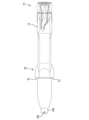
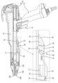
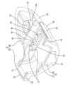
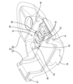
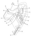
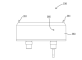
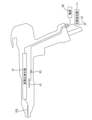
本実施例1の静電塗装ガンは、粉体塗料を使用して静電塗装を行う場合に用いられ、作業者が把持して塗装を行うためのハンドガンに適用したものである。図1~4に示すように、静電塗装ガンは、ガン本体10と電界制御部材30とを組み付けて構成されている。ガン本体10は、作業者が把持するための縦長のグリップ11と、グリップ11の上端部に連なって前後方向に延びたボディ12とを有する。グリップ11には、トリガ13が設けられている。The electrostatic coating gun of this Example 1 is used when electrostatic coating is performed using powder paint, and is applied to a handgun that an operator holds to perform coating. As shown in Figures 1 to 4, the electrostatic coating gun is configured by assembling a
図4に示すように、ボディ12の内部には、高電圧を発生させる高電圧発生器14が収容されている。高電圧発生器14は、電源90(図16参照)側から入力される交流電圧を高電圧の直流電圧に変換して出力する。高電圧発生器14は、トランスと、昇圧回路と、出力抵抗とを有している。昇圧回路は、例えばコッククロフト・ウォルトン型の昇圧整流回路で構成されている。昇圧回路は、トランスから入力された交流電圧を昇圧及び整流して直流の高電圧に変換する。昇圧回路の出力側は、例えば金属線によって出力抵抗に接続されている。As shown in FIG. 4, a
図4に示すように、ボディ12の前端部には、ノズル15Aと、ノズルキャップ15Bと、キャップナット15Cと、放電電極15Dと、が設けられている。ノズル15Aは、ガン本体10に供給された塗料を外部に噴霧させる。ノズルキャップ15Bは、キャップナット15Cを介してボディ12に連結されており、ノズル15Aの前端側の周囲を覆っている。放電電極15Dは、例えば金属製であり、ピン状をなしている。ピン状には、針状も含まれる。放電電極15Dには、高電圧発生器14の出力抵抗が接続されており、高電圧発生器14から出力された高電圧が印加され、放電電極15Dの先端部でコロナ放電が生じ、印加された高電圧と同極性のイオンが生成される。放電電極15D近傍で生成されたイオンは、ノズル15Aから噴霧される塗料を帯電させる。As shown in FIG. 4, the front end of the
図4に示すように、ボディ12の外周面には、電界制御部材30を取り付けるための取付部16が設けられている。取付部16は、ボディ12の下面側領域における前後方向中央部に配されている。取付部16の前端側部分は、ボディ12の下面の半周領域を凹ませた形態の左右対称な取付凹部17となっている。取付凹部17は、ボディ12の外周面のうち取付部16(取付凹部17)の内面前端部は、ボディ12の下面(外周面)に対して直角をなすストッパ18として機能する。ストッパ18における周方向中央部(ストッパ18の最下端部)には、横長のスリット状をなす係止孔19が形成されている。取付部16の後端部には、軸線を上下方向に向けた雌ネジ孔20が形成されている。雌ネジ孔20の軸線方向は、ストッパ18における係止孔19の開口方向と直交する方向である。As shown in FIG. 4, the outer peripheral surface of the
取付部16の前後方向中央部(係止孔19と雌ネジ孔20との間)には、ボディ12の内部と外部を連通させる方形の開口部21が形成されている(図15参照)。開口部21は、ボディ12及び取付部16の左右方向中央部よりも右側に偏った領域に開口している。図15に示すように、開口部21には、ボディ12内に設けた弾性接続部材22が露出している。弾性接続部材22は、軸線を上下方向に向けた圧縮コイルバネからなる。弾性接続部材22は、圧着端子23と電線24を介すことより、ガン本体10(ボディ12)の後端部の接地部(図示省略)に接続されている。接地部は導電性樹脂材料からなり、グリップ11内のアース用導電路(図示省略)を介してアースされる。取付部16の下面のうち開口部21を包囲する方形領域は、シール面25として機能する。A
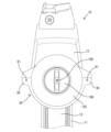
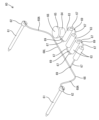
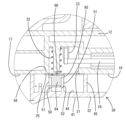
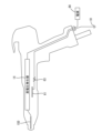
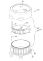
電界制御部材30は、ケース31と電極ユニット60とを一体化させたものである。ケース31は、合成樹脂製の保持部材32と、成形済み部品としての保持部材32に対し射出成形によって一体化された射出成形部55とから構成されている。図7~9に示すように、保持部材32は、湾曲部33と、湾曲部33から後方へ突出した皿状部40とを有し、単一部品として成形された部材である。保持部材32は、耐熱性の高い合成樹脂材料からなる。
The electric
保持部材32を前方から見た正面視において、湾曲部33は下方へ膨らんだ弧状をなしている。正面視における湾曲部33の外周面は、半円弧形をなす。湾曲部33の外周面の曲率半径は、ボディ12の外周面のうち取付部16の前端に隣接する前方隣接領域26(図1,4参照)の曲率半径よりも僅かに大きい。湾曲部33の前面における下端部(湾曲部33の周方向における中央部)には、前方へ板状に突出する係止部34が形成されている。In a front view of the retaining
図8に示すように、湾曲部33には、箱部35が形成されている。箱部35は、湾曲部33の内周面から上方へ立ち上がる左右対称な一対の側板部36と、両側板部36の上端縁同士を連結した形態の水平な上板部37とから構成される。箱部35の内部は前後両端面において開放されている。As shown in Fig. 8, a
湾曲部33の周方向における両端部には、左右対称な一対の電極用保持部38が形成されている。電極用保持部38は、径方向外方(左右方向)へ張り出し、前後方向にリブ状に延びた形状である。左右両電極用保持部38には、電極用保持部38を前後方向に貫通した形態の電極用保持孔39が形成されている。左右対称な一対の電極用保持孔39間の左右方向の間隔は、ボディ12の前方隣接領域26の直径寸法よりも大きい寸法である。A pair of symmetrical
保持部材32を上から見た平面視において、皿状部40は、左右対称な形状であり、後端部が尖ったショベル形をなしている。皿状部40の最大幅寸法(左右方向の寸法)は、湾曲部33の幅寸法よりも小さい。図1に示すように、皿状部40の外面は、平面からなる水平な下面部41と、左右対称な一対の側部連続面42と、後部連続面43とから構成されている。保持部材32を後方から見た背面視において、側部連続面42は、下面部41の左右両側縁から斜め上外側方へ延びている。In a plan view of the holding
保持部材32を側方から見た側面視において、後部連続面43は、曲率の小さい曲面からなり、下面部41の後端から斜め上後方へ延びている。後部連続面43は、下面部41の後縁及び左右両側部連続面42の後縁に連なっている。保持部材32を下から見た底面視において、後部連続面43(皿状部40の後端側領域)は、後端に向かって次第に幅狭となる形状である。In a side view of the retaining
皿状部40の前端部には、皿状部40の上面を凹ませた形態の収容凹部44が形成されている。前後方向において、収容凹部44は、電極用保持孔39の後端よりも後方の領域のみに形成されている。収容凹部44の前面壁は湾曲部33によって構成されている。収容凹部44の後面壁は、隔壁部45によって構成されている。収容凹部44の左右両面壁は、側部連続面42を有する左右両側壁部46によって構成されている。At the front end of the dish-shaped
収容凹部44内には、左右一対のリード線用保持部47が形成されている。一対のリード線用保持部47は、左右方向に間隔を空けて配置され、収容凹部44の底面のうち湾曲部33の後面(収容凹部44の前面)に近い位置から上方へ壁状に立ち上がっている。A pair of left and right
収容凹部44内には、収容凹部44の底面から上方へ突出した形態の抵抗用保持部48が形成されている。抵抗用保持部48には、複数(本実施例1では4つ)の抵抗用保持溝49が左右方向に並んで形成されている。抵抗用保持溝49は、抵抗用保持部48の上面と前後両面とに開口している。抵抗用保持溝49は、正面視形状が優弧である内周面を有する。A
収容凹部44内には、収容凹部44の底面から上方へ突出した形態のアース用保持部50が形成されている。アース用保持部50は、平面視形状が円弧形をなして同心状に配置された左右対称な一対のアース用保持突起51から構成されている。一対のアース用保持突起51の間には、アース用保持部50の上端から下方へ切り込んだ形態の前後一対の切欠部52が形成されている。Within the
皿状部40の後端部には、軸線を上下方向に向けた円筒形の固定部53が形成されている。固定部53の中空内は、皿状部40(保持部材32)を上下方向に貫通した形態の貫通孔54が形成されている。固定部53は、下面部41の後端部に配置されている。固定部53と係止部34は、保持部材32の左右方向中央に配置されている。固定部53と係止部34は、互いに前後方向に離隔した位置関係で配置されている。A cylindrical fixing
射出成形部55は、電極ユニット60の絶縁性を確保する目的で設けられ、絶縁性のホットメルト接着剤又は二液性樹脂からなる。射出成形部55は、第1成形部56と、左右対称な一対の第2成形部57とを有する。図5に示すように、第1成形部56は、射出成形部55のうち収容凹部44内に収容された部位である。第1成形部56は収容凹部44の全体に充填された形態である。第1成形部56の上面は、箱部35の上板部37の上面、及び隔壁部45の上面に対して同じ高さで面一状に連続している。第1成形部56の内部には、リード線用保持部47の全体と、抵抗用保持部48の全体と、アース用保持部50の全体とが埋設されている。The injection molded
第1成形部56の上面には、左右対称な一対のシール部58が形成されている。シール部58は、第1成形部56の上面から突出した形態である。シール部58の平面視形状は、長辺を前後方向に向けた長方形の枠形である。右側のシール部58は、平面視においてアース用保持部50を包囲するように配置されている。左右一対の第2成形部57は、第1成形部56の後端部から湾曲部33の後に沿って上方へ立ち上がった形態である。A pair of
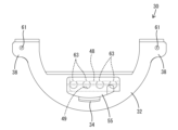
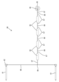
電極ユニット60は、図10,11に示すように、左右対称な一対の電極ピン61と、複数(本実施例1では4個)の抵抗素子63と、1つのアース部材64と、1本の金属製の長尺リード線68とを備えている。電極ピン61は、前後方向に細長い形状の金属部品である。電極ピン61はピン状をなしている。ピン状には、針状も含まれる。電極ピン61の前端は、放電電極15Dの前端よりも後方に配置される。電極ピン61の後端部には、径寸法を大きくした円形の大径部62が形成されている。抵抗素子63は、軸線を前後方向に向けた円筒形をなす。アース部材64は、軸線を上下方向に向けた円柱形の金属部品である。アース部材64の上端部には、径寸法を大きくした円形の拡径部65が形成されている。拡径部65の上面は接触面66として機能する。
As shown in Figs. 10 and 11, the
各抵抗素子63は、その前後両端から前後方向に延出する一対の短尺リード線67を有する。アース部材64は径方向外方へ延出する1本の短尺リード線67を有している。長尺リード線68と短尺リード線67は、いずれも、塑性変形が可能であり、各リード線67,68自体の剛性によって一定の形状を保持する形状保持性を有している。Each
電極ユニット60をケース31と一体化させる前の状態では、図10に示すように、一対の電極ユニット60が、前後方向を向けた状態で、左右に間隔を空けて配置されている。両電極ピン61の後端部(大径部62)同士は、直線状の長尺リード線68からなる導電路を介して接続されている。複数の抵抗素子63は、電極ピン61の後方において前後方向に直列状に並ぶように配置されている。アース部材64は、最後端の抵抗素子63よりも後方において、抵抗素子63の列に並ぶように配置されている。Before the
一対の電極ピン61と最前端の抵抗素子63は、長尺リード線68と最前端の抵抗素子63の短尺リード線67とを溶接69によってT字形に固着した導電路を介して接続されている。隣り合う抵抗素子63同士は、隣り合う抵抗素子63の短尺リード線67同士を溶接69によって一直線状に固着した導電路を介して接続されている。最後端の抵抗素子63とアース部材64は、抵抗素子63の短尺リード線67とアース部材64の短尺リード線67を溶接69によって一直線状に固着した導電路を介して接続されている。The pair of electrode pins 61 and the
次に、電極ユニット60をケース31と一体化させる工程を説明する。電極ユニット60を保持部材32に取り付ける前に、長尺リード線68と短尺リード線67を所定形状に曲げておく。これにより、図11に示すように、電極ピン61と抵抗素子63とアース部材64が、夫々、電極用保持部38と抵抗用保持部48とアース用保持部50の位置に合うように配置される。具体的には、一対の電極ピン61は、左右に間隔を空けて互いに平行をなすように配置される。複数の抵抗素子63は、短尺リード線67が前後方向に延出する向きで左右方向に並列される。並列した複数の抵抗素子63は、一対の電極ピン61の斜め下後方に配置され、左右方向においては一対の電極ピン61の間に配置されている。アース部材64は、抵抗素子63の列の右方近傍に配置されている。Next, the process of integrating the
長尺リード線68の両端部には、湾曲部33に沿うように円弧状に塑性変形させることによって、電極ピン61に連なる一対の弧状部位68Aが形成される。長尺リード線68のうち一対の弧状部位68Aの間の領域は、直線状部位68Lとなっている。抵抗素子63同士を接続する導電路(短尺リード線67)は、平面視において「コ字形」をなすように塑性変形させる。図10において最後端に位置する抵抗素子63とアース部材64とを接続する導電路(短尺リード線67)は、「L字形」をなすように塑性変形させる。At both ends of the
次に、上記の形態に変形させた電極ユニット60を、図12~14に示すように、電極ユニット60を保持部材32に仮組みする。このとき、電極ピン61を電極用保持部38の後方から電極用保持孔39に挿入して貫通させ、大径部62を湾曲部33の前面に当接させる。これにより電極ピン61は、保持部材32に対して上下方向及び左右方向に位置決めされるとともに、前方へ相対変位しないように位置決めされる。電極用保持部38の前方には、電極ピン61の前端部のみが突出している。
Next, the
長尺リード線68の弧状部位68Aは、湾曲部33の後面に沿うように配置される。長尺リード線68の弧状部位68Aのうち直線状部位68Lに連なる基端部は、収容凹部44内に収容される。直線状部位68Lの全体も、収容凹部44内に収容される。直線状部位68Lの左右両端部は、湾曲部33の後面とリード線用保持部47との間で前後方向に挟まれるように位置する。The arc-shaped
複数の抵抗素子63は、抵抗用保持部48の上方から複数の抵抗用保持溝49に個別に圧入される。これにより、抵抗素子63は、保持部材32に対して上下方向、左右方向及び前後方向に位置決めされる。アース部材64は、アース用保持部50の上方から一対のアース用保持突起51の間に圧入し、拡径部65をアース用保持突起51の上端に当接させる。これにより、アース部材64は、保持部材32に対して上下方向、左右方向及び前後方向に位置決めされる。複数の短尺リード線67は、抵抗用保持部48よりも前方又は後方に配置される。抵抗素子63、アース部材64、複数の短尺リード線67は、収容凹部44内に収容される。The
電極ユニット60を仮組みした保持部材32を、射出成形用の金型(図示省略)にセットする。金型内には、収容凹部44によって構成されるキャビティ(図示省略)と、湾曲部33と金型との間に構成されるキャビティ(図示省略)と、箱部35の内部空間によって構成されるキャビティ(図示省略)とが確保される。これらのキャビティ内には、溶融状態の絶縁性のホットメルト接着剤又は二液性樹脂が、加圧状態で注入される。The holding
加圧状態で注入されたホットメルト接着剤又は二液性樹脂は、射出圧によって保持部材32と電極ユニット60を構成する各部品61,62,63,64,67との間に充填され、電極ユニット60を構成する各部品の全体に隙間無く密着する。ホットメルト接着剤又は二液性樹脂は短時間で硬化する。ホットメルト接着剤又は二液性樹脂が硬化すると、射出成形部55が保持部材32と一体化した状態で成形されると同時に、ケース31(保持部材32及び射出成形部55)と電極ユニット60とが一体化される。以上により、電界制御部材30の製造が完了する。The hot melt adhesive or two-component resin injected under pressure is filled between the holding
射出成形部55が保持部材32と一体化した状態では、電極ユニット60の大部分が射出成形部55内に埋設される。電極ピン61に関しては、大径部62のみが射出成形部55に埋設されているが、電極ピン61のうち大径部62よりも前方の大部分は、射出成形部55の外部に位置する。アース部材64に関しては、拡径部65の上面(接触面66)は、射出成形部55の上面に露出しているが、拡径部65を含むアース部材64の全体は、射出成形部55の内部に埋設されている。左右両電極ピン61の前端部は、電極用保持孔39(電極用保持部38)の前方へ突出している。When the injection molded
ホットメルト接着剤又は二液性樹脂は加圧状態で射出されるため、射出圧によって電極ユニット60の位置ずれが懸念される。しかし、電極ピン61は電極用保持孔39に挿入され、大径部62が湾曲部33の後面に当接しているので、電極ピン61が保持部材32に対して位置ずれすることはない。長尺リード線68は、湾曲部33の後面とリード線用保持部47との間に挟まれているので、保持部材32に対して前後方向に位置ずれすることはない。抵抗素子63は、抵抗用保持溝49に圧入されているので、保持部材32に対して位置ずれすることはない。アース部材64は、アース用保持突起51の間で弾性的に挟み付けられているので、保持部材32に対して位置ずれすることはない。Since the hot melt adhesive or two-component resin is injected under pressure, there is concern that the
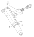
上記のようにして製造された電界制御部材30は、ガン本体10に取り付けられる。取り付ける際には、射出成形部55の上面が後方に向かって低くなるように電界制御部材30の姿勢を傾け、保持部材32の前端の係止部34をガン本体10の係止孔19に対して斜め下後方から嵌入する。電界制御部材30は、係止部34と係止孔19との係止部位を支点として、ガン本体10に対して上下方向へ揺動することが可能である。湾曲部33の前端を取付部16のストッパ18に当接させた状態で、係止部34と係止孔19の嵌合部分(係止孔19の開口縁における上縁)を支点として電界制御部材30を持ち上げる。この間、アース部材64の拡径部65を弾性接続部材22の下端に当接させ、弾性接続部材22を拡径部65の接触面66(上面)で押し上げて上下方向に弾縮させる。拡径部65の外径寸法は弾性接続部材22の外径寸法よりも大きいので、拡径部65と弾性接続部材22を確実に接触されることができる。The electric
アース部材64は、弾性接続部材22を介してアース91(図16参照)に接続される。つまり、上述した抵抗素子63は、図16に示すように、電極ピン61とアース91との間に設けられる。電極ピン61とアース91との間に抵抗素子63が設けられることで、抵抗素子63がない構成と比較して放電電極15Dの出力電流が低くなり、塗装対象物への電界強度が高まる。このため、塗装対象物に対する帯電塗料の塗着効率を向上させることができる。しかも、抵抗素子63が保持部材32に保持されて電界制御部材30として一体化されているため、抵抗素子63の数や種類を調整した電界制御部材30をガン本体10に取り付けることで、放電電極15Dの出力電流を調整することができる。The
左右両シール部58が、ガン本体10の取付部16の下面に当たると、固定部53の貫通孔54が、ガン本体10の雌ネジ孔20と上下に対向する状態となる。この後、ビス70を、保持部材32の下方から貫通孔54に挿入し、ガン本体10の雌ネジ孔20にねじ込む。ビス70を締め付けると、シール部58が弾性変形した状態でシール面25に対して液密状に密着する。ガン本体10の開口部21は右側のシール部58によってシールされるので、開口部21からガン本体10内への異物(粉体塗料)の進入が防止される。シール部58は左右対称に形成されているので、左側のシール部58がガン本体10の取付部16の下面に密着することにより、ガン本体10に対する保持部材32(電界制御部材30)が左右に傾くことが防止される。When both the left and
シール部58がガン本体10の取付部16の下面に密着すると、皿状部40がガン本体10の取付部16における後端側領域を覆い、湾曲部33が取付凹部17に嵌合される。ビス70の締付けを終了すると、ガン本体10に対する電界制御部材30の取付け工程が完了する。電界制御部材30は、ボディ12のうちノズル15Aよりも後方(ノズル15Aからの粉体塗料の吐出方向とは反対の方向)の位置に取り付けられる。電界制御部材30をガン本体10に取り付けた状態では、左右一対の電極ピン61の前端部が、ノズル15Aよりも後方において保持部材32(電極用保持部38)の前方へ突出(露出)した状態となっている。正面視及び平面視において、一対の電極ピン61は、ガン本体10の外周面の近傍に位置し、ガン本体10を左右両側から挟むように配置される。When the
静電塗装が行われると、ガン本体10に供給された粉体塗料が、高電圧発生器14によって帯電した状態でノズル15Aから前方へ吐出される。ノズル15Aから吐出された粉体塗料は、ノズル15Aと被塗面(図示省略)との間に発生する電界によって被塗面に塗着される。When electrostatic painting is performed, the powder paint supplied to the
静電塗装が行われている間、電界制御部材30は、ノズル15Aと電極ピン61との間にフリーイオンを吸収するための電界を発生させる。電界制御部材30が発生させる電界によって、被塗面に塗着した粉体塗料の粉体層におけるフリーイオンの量が低減される。これにより、粉体層にフリーイオンが残存することに起因する逆電離現象(静電反発)が抑制され、塗膜の平滑性が保たれる。During electrostatic painting, the electric
本実施例1の静電塗装ガンは、ガン本体10と、電界制御部材30とを備えている。ガン本体10の前端部には、粉体塗料を前方へ吐出させるためのノズル15Aが設けられている。電界制御部材30は、ガン本体10の外周面のうちノズル15Aよりも後方の位置に取り付けられている。電界制御部材30は、ノズル15Aとの間に電界を発生させる複数の電極ピン61と、複数の電極ピン61を周方向に間隔を空けて配置した状態で保持する保持部材32とを有している。The electrostatic coating gun of this
複数の電極ピン61を保持する保持部材32は、ガン本体10の外周面のうち周方向における一部のみを覆う形態である。ガン本体の外周面を全周に亘って覆うリング状の保持部材(図示省略)に比べると、本実施例1の保持部材32(電界制御部材30)は、小型化を実現することができる。電極ピン61を保持する部品は、保持部材32だけであるから、2つの部品で電極ピン61を保持する場合に比べると、部品点数が少なくて済む。The holding
電界制御部材30は、保持部材32と一体をなすように形成された合成樹脂製の射出成形部55を有している。電極ユニット60は電極ピン61を含んでいる。射出成形部55には、電極ユニット60における電極ピン61の前端部を除いた部位のうち、少なくとも一部が埋設されている。ここで、「埋設」の形態は、射出成形部55の内部に埋め込まれていて射出成形部55の外面から露出しない形態と、射出成形部55の外面に露出しているが射出成形部55の外面からは突出していない形態とを含む。The electric
本実施例1では、電極ユニット60における電極ピン61の前端部を除いた部位のうち、少なくとも一部(電極ピン61を除いた部位)が、射出成形部55内に埋設されている。この構成によれば、射出成形工程では、射出圧によって合成樹脂材料(ホットメルト接着剤又は二液性樹脂)が電極ユニット60に密着するので、射出成形部55と電極ユニット60との間に隙間が生じることはない。これにより、静電塗装の際に、電極ユニット60のうち電極ピン61以外の部位に地絡することを防止できる。In this
電極ユニット60は、電極ピン61と抵抗素子63とアース部材64を含んでいる。保持部材32には、電極ピン61を保持する電極用保持部38が形成されているので、射出成形工程において、電極ピン61が射出圧によって位置ずれすることを防止できる。保持部材32には、抵抗素子63を位置決め状態に保持する抵抗用保持部48が形成されているので、射出成形工程において、抵抗素子63が射出圧によって位置ずれすることを防止できる。保持部材32には、アース部材64を位置決め状態に保持するアース用保持部50が形成されているので、射出成形工程において、アース部材64が射出圧によって位置ずれすることを防止できる。The
電極ユニット60は、ガン本体10に設けたアース用の弾性接続部材22と接続可能なアース部材64を含んでいる。射出成形部55の外面には、アース部材64の接触面66が露出している。射出成形部55の外面には、射出成形部55の外面におけるアース部材64の露出部分(接触面66)を包囲するシール部58が一体形成されている。シール部58はガン本体10に対して液密状に密着している。この構成によれば、射出成形部55とは別体のシール部58を設けなくても、弾性接続部材22とアース部材64との接続部分への被水や、ガン本体10内への異物の進入などを防止することができる。The
保持部材32は、ガン本体10に対して揺動可能に嵌合する係止部34と、ガン本体10に対し締結部材(ビス70)によって固定される固定部53とを有している。この構成によれば、ガン本体10に対する保持部材32の取り付けを、複数の締結部材によって行う場合に比べると、締結部材(ビス70)によって固定される固定部53を1箇所だけにすることができる。これにより、ガン本体10に保持部材32を取り付ける際の作業性が良好である。The retaining
ガン本体10にはアース用の弾性接続部材22が設けられている。保持部材32には、保持部材32をガン本体10に取り付けた状態で弾性接続部材22に接続されるアース部材64が設けられている。アース部材64には、弾性接続部材22を弾性変形させた状態で接触させる接触面66が形成されている。接触面66の外径寸法は弾性接続部材22の外径寸法よりも大きい。この構成によれば、弾性接続部材22を、弾性変形させながら接触面66に接触させるだけでアース部材64に接続させることができるので、作業性が良い。The
保持部材32の外面には、ガン本体10の外周面に対して鈍角をなして連なる側部連続面42と後部連続面43が形成されている。側部連続面42は、ボディ12の外周面における側面領域に対して溝、隙間、凹み等を介すことなく連続している。後部連続面43は、ボディ12の外周面における底面領域に対して溝、隙間、凹み等を介すことなく連続している。この構成によれば、ガン本体10の外周面と保持部材32の外面(側部連続面42及び後部連続面43)との境界部分に粉体塗料が残留し難い。仮に、ガン本体10の外周面と保持部材32の外面(側部連続面42及び後部連続面43)との境界部分に粉体塗料が残留しても、塗料を除去し易く、洗浄性に優れている。The outer surface of the holding
<実施例2>
電界制御部材は、上記実施例1の形状に限らない。本実施例2では、電界制御部材が環状である例について説明する。以下、実施例2を図17~図19を参照して説明する。尚、以下の説明において、実施例1と同じ構成については同じ符号を付し、詳しい説明を省略する。
Example 2
The shape of the electric field control member is not limited to that of the first embodiment. In the second embodiment, an example in which the electric field control member is annular will be described. The second embodiment will be described below with reference to Figs. 17 to 19. In the following description, the same components as those in the first embodiment will be denoted by the same reference numerals, and detailed description will be omitted.
本実施例2の静電塗装ガンは、図17に示すように、ガン本体210を備えている。ガン本体210は、グリップ11と、ボディ212と、を有する。ボディ212の内部には、実施例1のボディ12と同じく、高電圧発生器14、放電電極15Dなどが設けられている。ボディ212の外周には、電界制御部材230が取り付けられる。
The electrostatic coating gun of this Example 2 includes a
電界制御部材230は、図18及び図19に示すように、保持部材232と、左右一対の電極ピン261と、抵抗素子263と、アース部材264と、リード線268と、を有する。リード線268の一端側には、一対の電極ピン261が間隔をあけて設けられ、リード線268の他端側には、アース部材264が設けられ、リード線268において一対の電極ピン261とアース部材264との間には、抵抗素子263が設けられている。アース部材264は、アース91(図16参照)に接続される。つまり、抵抗素子263は、電極ピン261とアース91との間に設けられる。18 and 19, the electric
保持部材232は、合成樹脂製であり、環状、具体的には円環状をなしている。保持部材232は、環状の内側部材281と、内側部材281の外側に配置される環状の外側部材282と、を有する。内側部材281は、環状部283と、環状部283の軸方向の一端から径方向外側に延設されたフランジ部284と、を有する。外側部材282は、内側部材281の軸方向の他端側から嵌め込まれ、フランジ部284にネジ止めされる。The retaining
内側部材281と外側部材282の径方向の間には、左右一対の電極ピン261の前端部を除く部位と、抵抗素子263と、が配置され、この状態で、左右一対の電極ピン261と、抵抗素子263とが、保持部材232に保持される。左右一対の電極ピン261の前端部は、図17及び図18に示すように、保持部材232の外部に露出する。
The pair of left and right electrode pins 261, except for their front ends, and the
保持部材232の外側部材282には、図18及び図19に示すように、樹脂注入口285が形成されている。樹脂注入口285から樹脂が注入されることで、保持部材232内に図示しない樹脂成形部が形成される。樹脂成形部には、抵抗素子263及び電極ピン261の前端部を除く部位が埋設される。保持部材232は、図17に示すように、ガン本体210に取り付けられる。18 and 19, a
<実施例3>
本実施例3では、図20を参照して、可変抵抗器71が設けられる構成について説明する。尚、以下の説明において、実施例1と同じ構成については同じ符号を付し、詳しい説明を省略する。
Example 3
In the present embodiment, a configuration in which a variable resistor 71 is provided will be described with reference to Fig. 20. In the following description, the same components as those in the
図20に示すように、抵抗素子63とアース91との間には、可変抵抗器71が設けられる。この構成によれば、抵抗素子63だけでなく、可変抵抗器71によっても放電電極15Dの出力電流を調整することができる。20, a variable resistor 71 is provided between the
<他の実施例>
本発明は上記記述及び図面によって説明した実施例に限定されるものではなく、例えば次のような実施例も本発明の技術的範囲に含まれる。
上記実施例1では、弾性接続部材とアース部材との接続部分への被水を防止する手段として、射出成形部にシール部を一体に形成したが、射出成形部とは別体のシール部材を用いて、弾性接続部材とアース部材との接続部分への被水を防止してもよい。
上記実施例1では、保持部材を1つの係止部と1つの固定部によってガン本体に取り付けたが、保持部材をガン本体に取り付ける手段として、複数の係止部を用いてもよく、複数の固定部を設けてもよい。
上記実施例1では、ガン本体に対する保持部材の取り付けと、弾性接続部材に対するアース部材の接続を、ワンアクションで行えるようにしたが、ガン本体に対する保持部材の取り付けと、弾性接続部材に対するアース部材の接続を、別々の作業で行うようにしてもよい。
上記実施例1及び2では、電極ピンが2本であるが、電極ピンの本数は1本であってもよいし、3本以上であってもよい。
上記実施例1~3では、作業者が把持して塗装を行うためのハンドガンに適用した静電塗装ガンについて説明したが、本発明は、レシプロケータやロボットに取り付けた自動ガンにも適用することができる。
<Other Examples>
The present invention is not limited to the embodiments described above and illustrated in the drawings, and the following embodiments are also included within the technical scope of the present invention.
In the above-mentioned Example 1, a seal portion is integrally formed with the injection molded portion as a means for preventing water from getting into the connection portion between the elastic connecting member and the earth member. However, a seal member separate from the injection molded portion may be used to prevent water from getting into the connection portion between the elastic connecting member and the earth member.
In the above-mentioned Example 1, the retaining member is attached to the gun body by one locking portion and one fixing portion, but multiple locking portions may be used or multiple fixing portions may be provided as a means for attaching the retaining member to the gun body.
In the above-mentioned Example 1, the attachment of the holding member to the gun body and the connection of the earth member to the elastic connecting member can be performed in a single action, but the attachment of the holding member to the gun body and the connection of the earth member to the elastic connecting member may be performed in separate operations.
In the above-mentioned first and second embodiments, the number of electrode pins is two, but the number of electrode pins may be one, or three or more.
In the
10…ガン本体、11…グリップ、12…ボディ、13…トリガ、14…高電圧発生器、15A…ノズル、15B…ノズルキャップ、15C…キャップナット、15D…放電電極、16…取付部、17…取付凹部、18…ストッパ、19…係止孔、20…雌ネジ孔、21…開口部、22…弾性接続部材、23…圧着端子、24…電線、25…シール面、26…前方隣接領域、30…電界制御部材、31…ケース、32…保持部材、33…湾曲部、34…係止部、35…箱部、36…側板部、37…上板部、38…電極用保持部、39…電極用保持孔、40…皿状部、41…下面部、42…側部連続面(連続面)、43…後部連続面(連続面)、44…収容凹部、45…隔壁部、46…左右両側壁部、47…リード線用保持部、48…抵抗用保持部、49…抵抗用保持溝、50…アース用保持部、51…アース用保持突起、52…切欠部、53…固定部、54…貫通孔、55…射出成形部、56…第1成形部、57…第2成形部、58…シール部、60…電極ユニット、61…電極ピン、62…大径部、63…抵抗素子、64…アース部材、65…拡径部、66…接触面、67…短尺リード線、68…長尺リード線、68A…弧状部位、68L…直線状部位、69…溶接、70…ビス(締結部材)、71…可変抵抗器、90…電源、91…アース、210…ガン本体、212…ボディ、230…電界制御部材、232…保持部材、261…電極ピン、263…抵抗素子、264…アース部材、268…リード線、281…内側部材、282…外側部材、283…環状部、284…フランジ部、285…樹脂注入口10...Gun body, 11...Grip, 12...Body, 13...Trigger, 14...High voltage generator, 15A...Nozzle, 15B...Nozzle cap, 15C...Cap nut, 15D...Discharge electrode, 16...Mounting portion, 17...Mounting recess, 18...Stopper, 19...Engagement hole, 20...Female thread hole, 21...Opening, 22...Elastic connecting member, 23...Crimp terminal, 24...Electric wire, 25...Seal surface, 26...Front adjacent region, 3 0...electric field control member, 31...case, 32...holding member, 33...curved portion, 34...locking portion, 35...box portion, 36...side plate portion, 37...upper plate portion, 38...electrode holding portion, 39...electrode holding hole, 40...dish-shaped portion, 41...lower surface portion, 42...side continuous surface (continuous surface), 43...rear continuous surface (continuous surface), 44...accommodating recess, 45...partition wall portion, 46...left and right side wall portions, 47...lead wire holding portion, 48...resistor holding portion, 49... Resistor holding groove, 50...Earth holding portion, 51...Earth holding protrusion, 52...Notch, 53...Fixed portion, 54...Through hole, 55...Injection molded portion, 56...First molded portion, 57...Second molded portion, 58...Sealed portion, 60...Electrode unit, 61...Electrode pin, 62...Large diameter portion, 63...Resistance element, 64...Earth member, 65...Expanded diameter portion, 66...Contact surface, 67...Short lead wire, 68...Long lead wire, 68A...Arc-shaped portion , 68L...straight portion, 69...welding, 70...screw (fastening member), 71...variable resistor, 90...power source, 91...earth, 210...gun main body, 212...body, 230...electric field control member, 232...holding member, 261...electrode pin, 263...resistance element, 264...earth member, 268...lead wire, 281...inner member, 282...outer member, 283...annular portion, 284...flange portion, 285...resin injection port
Claims (11)
前記ガン本体の前端部に設けたノズルと、
前記ノズルから噴霧される塗料を帯電させるためのピン状の放電電極と、
前記放電電極との間に電界を発生させる少なくとも1つの電極ピンと、
前記ガン本体に取り付けられる電界制御部材とを備え、
前記電界制御部材は、前記電極ピンと、前記電極ピンを保持する保持部材と、を有しており、
前記電界制御部材は、前記電極ピンとアースとの間の経路に設けられる抵抗素子を有しており、
前記抵抗素子は、前記保持部材に保持されている静電塗装ガン。 The gun body and
A nozzle provided at a front end of the gun body;
A pin-shaped discharge electrode for charging the paint sprayed from the nozzle;
At least one electrode pin that generates an electric field between itself and the discharge electrode;
An electric field control member attached to the gun body ,
the electric field control member has the electrode pin and a holding member that holds the electrode pin,
the electric field control member has a resistive element provided in a path between the electrode pin and ground,
The resistance element is held by the holding member of the electrostatic spray gun.
前記射出成形部には、前記抵抗素子が埋設されている請求項1に記載の静電塗装ガン。 the electric field control member has an injection-molded part made of synthetic resin that is integral with the holding member,
2. The electrostatic spray gun according to claim 1 , wherein the resistance element is embedded in the injection molded portion.
前記射出成形部には、前記電極ピンを含む電極ユニットにおける前記電極ピンの前端部を除いた部位のうち、少なくとも一部が埋設されている請求項1から請求項3のいずれか1項に記載の静電塗装ガン。 the electric field control member has an injection-molded part made of synthetic resin that is integral with the holding member,
4. The electrostatic coating gun according to claim 1 , wherein at least a portion of an electrode unit including the electrode pin, excluding a front end portion of the electrode pin, is embedded in the injection molded portion.
前記射出成形部の外面には、前記射出成形部の外面における前記アース部材の露出部分を包囲するシール部が一体形成され、
前記シール部が前記ガン本体に対して液密状に密着している請求項2又は請求項4に記載の静電塗装ガン。 The electrode unit includes a grounding member connectable to an elastic connecting member for grounding provided on the gun body,
a seal portion is integrally formed on an outer surface of the injection molded portion to surround an exposed portion of the earth member on the outer surface of the injection molded portion;
5. The electrostatic spray gun according to claim 2, wherein the seal portion is in liquid-tight contact with the gun body.
前記ガン本体の前端部に設けたノズルと、
前記ノズルから噴霧される塗料を帯電させるためのピン状の放電電極と、
前記放電電極との間に電界を発生させる少なくとも1つの電極ピンと、
前記ガン本体に取り付けられる電界制御部材とを備え、
前記電界制御部材は、前記電極ピンと、前記電極ピンを保持する保持部材と、を有しており、
前記保持部材は、前記ガン本体の外周面のうち周方向における一部のみを覆う形態である静電塗装ガン。 The gun body and
A nozzle provided at a front end of the gun body;
A pin-shaped discharge electrode for charging the paint sprayed from the nozzle;
At least one electrode pin that generates an electric field between itself and the discharge electrode;
An electric field control member attached to the gun body,
the electric field control member has the electrode pin and a holding member that holds the electrode pin,
The holding member covers only a portion of the outer circumferential surface of the gun body in the circumferential direction.
前記保持部材には、前記抵抗素子を位置決め状態に保持する抵抗用保持部が形成されている請求項6又は請求項7に記載の静電塗装ガン。 The electrode unit includes a resistive element,
8. The electrostatic spray gun according to claim 6 , wherein the holding member is formed with a resistor holding portion for holding the resistor element in a positioned state.
前記ガン本体に対して揺動可能に嵌合する係止部と、
前記ガン本体に対し締結部材によって固定される固定部とを有している請求項6から請求項8のいずれか1項に記載の静電塗装ガン。 The holding member is
A locking portion that is fitted to the gun body so as to be capable of swinging;
9. The electrostatic spray gun according to claim 6 , further comprising a fixing portion fixed to the gun body by a fastening member.
前記保持部材には、前記保持部材を前記ガン本体に取り付けた状態で前記弾性接続部材に接続されるアース部材が設けられ、
前記アース部材には、前記弾性接続部材を弾性変形させた状態で接触させる接触面が形成されている請求項6から請求項9のいずれか1項に記載の静電塗装ガン。 The gun body is provided with an elastic connection member for earthing,
The holding member is provided with an earth member that is connected to the elastic connecting member in a state in which the holding member is attached to the gun body,
10. The electrostatic spray gun according to claim 6 , wherein the earth member has a contact surface with which the elastic connection member comes into contact in an elastically deformed state.
Applications Claiming Priority (1)
| Application Number | Priority Date | Filing Date | Title |
|---|---|---|---|
| PCT/JP2021/046796 WO2023112319A1 (en) | 2021-12-17 | 2021-12-17 | Electrostatic coating gun |
Publications (2)
| Publication Number | Publication Date |
|---|---|
| JPWO2023112319A1 JPWO2023112319A1 (en) | 2023-06-22 |
| JP7621691B2 true JP7621691B2 (en) | 2025-01-27 |
Family
ID=86773976
Family Applications (1)
| Application Number | Title | Priority Date | Filing Date |
|---|---|---|---|
| JP2023567488A Active JP7621691B2 (en) | 2021-12-17 | 2021-12-17 | Electrostatic Paint Gun |
Country Status (3)
| Country | Link |
|---|---|
| JP (1) | JP7621691B2 (en) |
| CN (1) | CN118159364A (en) |
| WO (1) | WO2023112319A1 (en) |
Citations (4)
| Publication number | Priority date | Publication date | Assignee | Title |
|---|---|---|---|---|
| WO2004085078A1 (en) | 2003-03-27 | 2004-10-07 | Asahi Sunac Corporation | Electrostatic coating spray gun |
| WO2008038035A1 (en) | 2006-09-27 | 2008-04-03 | Yu Tung Investment Holdings Limited | Powder spray coating discharge assembly |
| WO2009069396A1 (en) | 2007-11-30 | 2009-06-04 | Abb K.K. | Electrostaic coating device |
| JP2015166073A (en) | 2014-03-04 | 2015-09-24 | 旭サナック株式会社 | Electrostatic coating equipment |
Family Cites Families (3)
| Publication number | Priority date | Publication date | Assignee | Title |
|---|---|---|---|---|
| JPS62190649U (en) * | 1986-05-27 | 1987-12-04 | ||
| JPS63162056A (en) * | 1986-12-24 | 1988-07-05 | Trinity Ind Corp | Electrostatic oil coating machine |
| JP4578908B2 (en) * | 2004-09-17 | 2010-11-10 | トヨタ自動車株式会社 | Electrostatic coating equipment |
-
2021
- 2021-12-17 CN CN202180103669.1A patent/CN118159364A/en active Pending
- 2021-12-17 WO PCT/JP2021/046796 patent/WO2023112319A1/en not_active Ceased
- 2021-12-17 JP JP2023567488A patent/JP7621691B2/en active Active
Patent Citations (4)
| Publication number | Priority date | Publication date | Assignee | Title |
|---|---|---|---|---|
| WO2004085078A1 (en) | 2003-03-27 | 2004-10-07 | Asahi Sunac Corporation | Electrostatic coating spray gun |
| WO2008038035A1 (en) | 2006-09-27 | 2008-04-03 | Yu Tung Investment Holdings Limited | Powder spray coating discharge assembly |
| WO2009069396A1 (en) | 2007-11-30 | 2009-06-04 | Abb K.K. | Electrostaic coating device |
| JP2015166073A (en) | 2014-03-04 | 2015-09-24 | 旭サナック株式会社 | Electrostatic coating equipment |
Also Published As
| Publication number | Publication date |
|---|---|
| WO2023112319A1 (en) | 2023-06-22 |
| JPWO2023112319A1 (en) | 2023-06-22 |
| CN118159364A (en) | 2024-06-07 |
Similar Documents
| Publication | Publication Date | Title |
|---|---|---|
| JP5668655B2 (en) | Conductive plate and joint connector | |
| US20220013945A1 (en) | Connector | |
| JP5513061B2 (en) | Electrostatic coating system and spray gun for electrostatic coating | |
| JPH02241561A (en) | Spray gun for electro static painting | |
| US10797413B2 (en) | Terminal-equipped electrical wire and wiring module | |
| CN100449892C (en) | ion generating unit | |
| US20180069339A1 (en) | Terminal module | |
| JP7621691B2 (en) | Electrostatic Paint Gun | |
| US20140139965A1 (en) | Surge arrester | |
| TWI821827B (en) | Electrostatic coating spray gun | |
| JP2011034937A (en) | Connector | |
| JP2019160728A (en) | Power storage device | |
| CN113423509A (en) | Rear housing for a spray gun and spray gun having such a rear housing | |
| US7049737B2 (en) | Anode-terminal cover and display having the same | |
| JP2017208248A (en) | Charging connector | |
| KR101197916B1 (en) | Power Terminal Assembly For Welder | |
| JP5031089B2 (en) | Discharge lamp lighting device | |
| WO2018179491A1 (en) | Electrostatic spray nozzle and electrostatic spray apparatus | |
| JP7578857B1 (en) | Static electricity eliminator | |
| US20240382984A1 (en) | Electrostatic Spraying Device | |
| WO2021095475A1 (en) | Waterproof connector | |
| KR200481954Y1 (en) | Screw bushing for car battery | |
| JP2007317453A (en) | Lamp socket, discharge lamp starting device and headlamp device | |
| JP2025181198A (en) | Additional parts applicable to electrostatic coating device, and electrostatic coating device | |
| JP5859909B2 (en) | Cable integrated plug and manufacturing method thereof |
Legal Events
| Date | Code | Title | Description |
|---|---|---|---|
| A621 | Written request for application examination |
Free format text: JAPANESE INTERMEDIATE CODE: A621 Effective date: 20240308 |
|
| A131 | Notification of reasons for refusal |
Free format text: JAPANESE INTERMEDIATE CODE: A131 Effective date: 20240808 |
|
| A521 | Request for written amendment filed |
Free format text: JAPANESE INTERMEDIATE CODE: A523 Effective date: 20241002 |
|
| TRDD | Decision of grant or rejection written | ||
| A01 | Written decision to grant a patent or to grant a registration (utility model) |
Free format text: JAPANESE INTERMEDIATE CODE: A01 Effective date: 20250106 |
|
| A61 | First payment of annual fees (during grant procedure) |
Free format text: JAPANESE INTERMEDIATE CODE: A61 Effective date: 20250107 |
|
| R150 | Certificate of patent or registration of utility model |
Ref document number: 7621691 Country of ref document: JP Free format text: JAPANESE INTERMEDIATE CODE: R150 |