JP7621604B2 - Topping rubber sheet rubber attachment defect detection device - Google Patents
Topping rubber sheet rubber attachment defect detection device Download PDFInfo
- Publication number
- JP7621604B2 JP7621604B2 JP2021003468A JP2021003468A JP7621604B2 JP 7621604 B2 JP7621604 B2 JP 7621604B2 JP 2021003468 A JP2021003468 A JP 2021003468A JP 2021003468 A JP2021003468 A JP 2021003468A JP 7621604 B2 JP7621604 B2 JP 7621604B2
- Authority
- JP
- Japan
- Prior art keywords
- topping rubber
- rubber sheet
- sheet
- topping
- image data
- Prior art date
- Legal status (The legal status is an assumption and is not a legal conclusion. Google has not performed a legal analysis and makes no representation as to the accuracy of the status listed.)
- Active
Links
Images
Landscapes
- Investigating Materials By The Use Of Optical Means Adapted For Particular Applications (AREA)
- Tyre Moulding (AREA)
Description
本発明は、黒色のテキスタイルシートに黒色のトッピングゴムが被覆(トッピング)されたトッピングゴムシートにおけるトッピングゴムの被覆状態を検査して、トッピングゴムシートのゴム付き不良の発生を検出するトッピングゴムシートのゴム付き不良検出装置に関する。 The present invention relates to a topping rubber sheet rubber attachment defect detection device that inspects the state of topping rubber in a topping rubber sheet in which a black textile sheet is covered (topped) with black topping rubber, and detects the occurrence of rubber attachment defects in the topping rubber sheet.
空気入りタイヤ(以下、単に、「タイヤ」ともいう)の製造に際しては、コード材料を織って構成されたテキスタイルシートの両面にゴム(トッピングゴム)が被覆されたトッピングゴムシートが、カーカスやベルト、ブレーカ等のタイヤ部材として使用されている。 In the manufacture of pneumatic tires (hereinafter simply referred to as "tires"), a topping rubber sheet, which is made by covering both sides of a textile sheet made of woven cord material with rubber (topping rubber), is used as tire components such as the carcass, belt, and breaker.
このとき、トッピングゴムのテキスタイルシートへのゴム付きが不十分な状態(ゴム付き不良)が発生すると、タイヤの品質不良を招く恐れがあるため、トッピングゴムの被覆状態について十分な検査を行い、ゴム付き不良の発生を検出する必要があり、作業者の目視観察により検査が行われていた。 At this time, if the topping rubber is not sufficiently attached to the textile sheet (poor rubber attachment), this can lead to poor tire quality, so it is necessary to thoroughly inspect the topping rubber coating condition to detect any poor rubber attachment, and inspections are currently carried out by workers through visual observation.
具体的には、ゴム付きが不十分な場合、テキスタイルシートの一部が、トッピングゴムシートから露出するため、トッピングゴムシートの上方からテキスタイルシートが見えるか否か、目視観察により検査を行っていた。 Specifically, if the rubber attachment is insufficient, part of the textile sheet will be exposed from the topping rubber sheet, so inspections were conducted by visual observation to see whether the textile sheet was visible from above the topping rubber sheet.
しかし、作業者の目視観察では、十分とは言えなかったため、ラインセンサカメラを備えたトッピングゴムシートのゴム付き不良検出装置(以下、単に「検出装置」ともいう)を用いて、トッピングゴムシートの表面に光を照射し、その反射光による画像を撮影した後、撮影された画像データをデータ処理することにより、色の違いからトッピングゴムの被覆状態を検査して、ゴム付き不良の発生を検出する技術が種々提案されている(例えば、特許文献1、2)。
However, visual observation by an operator is not sufficient, so various techniques have been proposed to use a topping rubber sheet rubber attachment defect detection device (hereinafter simply referred to as a "detection device") equipped with a line sensor camera to irradiate light onto the surface of the topping rubber sheet, capture an image using the reflected light, and then process the captured image data to inspect the topping rubber coating condition from color differences and detect the occurrence of rubber attachment defects (e.g.,
しかしながら、近年、タイヤに求められる特性(転がり抵抗、耐久性、路面状況、走行状況、乗り心地など)との関係から、テキスタイルシートとして黒色のテキスタイルシートの採用が求められるようになり、上記した従来の技術では、テキスタイルシートとトッピングゴムが同じ黒色であるため、テキスタイルシートとトッピングゴムを区別することが困難となっていた。 However, in recent years, there has been a demand for black textile sheets in relation to the characteristics required of tires (rolling resistance, durability, road conditions, driving conditions, ride comfort, etc.), and with the conventional technology described above, the textile sheet and the topping rubber are both black in color, making it difficult to distinguish between them.
ラインセンサカメラに替えて、厚み計を使用してトッピングゴムシートの厚みを計測し、その変化を知ることにより、テキスタイルシートとトッピングゴムを区別して、ゴム付き不良の発生を検出することも試みられているが、測定できる範囲は限定的であり、トッピングゴムシートのように厚みのある材料については、高い精度で、安定して検出することが難しく、さらなる改善が求められている。 Instead of using a line sensor camera, attempts have been made to use a thickness gauge to measure the thickness of the topping rubber sheet and detect any changes in the thickness in order to distinguish between the textile sheet and the topping rubber and detect any rubber attachment defects. However, the range that can be measured is limited, and it is difficult to detect thick materials such as topping rubber sheets with high accuracy and stability, so further improvements are required.
そこで、本発明は、トッピングゴムシートのように厚みのある材料であっても、同じ黒色をしたテキスタイルシートとトッピングゴムとを精度高く区別して、テキスタイルシートへのトッピングゴムの被覆状態を知ることにより、ゴム付き不良の発生を安定して検出することができるトッピングゴムシートのゴム付き不良検出装置を提供することを課題とする。 The present invention aims to provide a device for detecting defects in rubber attachment of topping rubber sheets that can accurately distinguish between textile sheets and topping rubber, both of which are the same black color, even in the case of a thick material such as a topping rubber sheet, and can stably detect the occurrence of defects in rubber attachment by knowing the state in which the topping rubber is coated on the textile sheet.
本発明者は、上記課題の解決について鋭意検討を行い、以下に記載する発明により上記課題が解決できることを見出し、本発明を完成させるに至った。 The inventors conducted extensive research into solving the above problems and discovered that the invention described below can solve the above problems, leading to the completion of the present invention.
請求項1に記載の発明は、
黒色のテキスタイルシートに黒色のトッピングゴムが被覆されたトッピングゴムシートにおけるゴム付き不良の発生を検出するトッピングゴムシートのゴム付き不良検出装置であって、
前記トッピングゴムシートの表面を撮影して画像データを取得する画像データ取得手段と、
前記画像データ取得手段により取得された画像データを画像処理して、前記トッピングゴムシートにおけるゴム付き不良の発生を検出する検出手段とを備えており、
前記画像データ取得手段は、
前記トッピングゴムシートの表面を連続的に照射する照射装置と、
前記照射装置から照射され、前記トッピングゴムシートの表面で反射した反射光を受光して、画像データを取得するラインセンサカメラとを備えており、
前記反射光の内、拡散反射光が前記ラインセンサカメラに入光するように、前記照射装置と前記ラインセンサカメラとが配置されており、
前記照射装置における照射源が、赤外光LEDであることを特徴とするトッピングゴムシートのゴム付き不良検出装置である。
The invention described in
A topping rubber sheet rubber attachment failure detection device for detecting occurrence of a rubber attachment failure in a topping rubber sheet in which a black textile sheet is covered with a black topping rubber, comprising:
An image data acquisition means for acquiring image data by photographing the surface of the topping rubber sheet;
and a detection means for detecting occurrence of a rubber attachment defect in the topping rubber sheet by performing image processing on the image data acquired by the image data acquisition means,
The image data acquisition means includes:
an irradiation device for continuously irradiating the surface of the topping rubber sheet;
a line sensor camera that receives light irradiated from the irradiation device and reflected on the surface of the topping rubber sheet to obtain image data,
the irradiation device and the line sensor camera are disposed so that diffuse reflected light of the reflected light enters the line sensor camera;
The device for detecting defective rubber attachment of a topping rubber sheet is characterized in that the irradiation source in the irradiation device is an infrared light LED .
請求項2に記載の発明は、
前記赤外光LEDから照射される光が、波長850~940nmの赤外光であることを特徴とする請求項1に記載のトッピングゴムシートのゴム付き不良検出装置である。
The invention described in claim 2 is
2. The device for detecting a defect in rubber attachment of a topping rubber sheet according to
請求項3に記載の発明は、
前記照射装置が、前記トッピングゴムシートの表面に対して、5~45°の入射角で、赤外光が照射されるように配置されていることを特徴とする請求項1または請求項2に記載のトッピングゴムシートのゴム付き不良検出装置である。
The invention described in claim 3 is
This is a topping rubber sheet rubber attachment defect detection device as described in
請求項4に記載の発明は、
前記画像データ取得手段が、トッピングゴムシートの搬送位置を計測するエンコーダを備えており、
前記ラインセンサカメラによる撮影データを、前記エンコーダによる位置情報と同期させて取得するように構成されていることを特徴とする請求項1ないし請求項3のいずれか1項に記載のトッピングゴムシートのゴム付き不良検出装置である。
The invention described in claim 4 is
The image data acquisition means includes an encoder for measuring a conveying position of the topping rubber sheet,
This is a topping rubber sheet rubber attachment defect detection device as described in any one of
請求項5に記載の発明は、
前記画像処理が、濃淡プロブモードによる画像処理であり、
前記検出手段が、得られた画像処理データから、濃黒色部分をテキスタイルシート部分として検出することを特徴とする請求項1ないし請求項4のいずれか1項に記載のトッピングゴムシートのゴム付き不良検出装置である。
The invention described in claim 5 is
The image processing is image processing in a gray-scale probe mode,
5. The device for detecting defects in rubber attachment of a topping rubber sheet according to
請求項6に記載の発明は、
さらに、前記検出手段により検出された前記テキスタイルシートの部分の面積が、予め定めた閾値以上の場合に、ゴム付き不良の発生が検出されたと判断して、警告信号を出す警告出力手段を備えていることを特徴とする請求項1ないし請求項5のいずれか1項に記載のトッピングゴムシートのゴム付き不良検出装置である。
The invention described in claim 6 is
The device for detecting rubber attachment defects in a topping rubber sheet as described in any one of
本発明によれば、トッピングゴムシートのように厚みのある材料であっても、同じ黒色をしたテキスタイルシートとトッピングゴムとを精度高く区別して、テキスタイルシートへのトッピングゴムの被覆状態を知ることにより、ゴム付き不良の発生を安定して検出することができるトッピングゴムシートのゴム付き不良検出装置を提供することができる。 According to the present invention, it is possible to provide a topping rubber sheet rubber attachment defect detection device that can accurately distinguish between a textile sheet and topping rubber, both of which are the same black color, even in the case of a thick material such as a topping rubber sheet, and by knowing the state of topping rubber covering the textile sheet, it is possible to stably detect the occurrence of rubber attachment defects.
1.本発明に係るトッピングゴムシートのゴム付き不良検出装置の特徴
最初に、本発明に係るトッピングゴムシートのゴム付き不良検出装置の特徴について説明する。
1. Features of the Device for Detecting Defective Rubber Attachment of a Topping Rubber Sheet According to the Present Invention First, the features of the device for detecting defective rubber attachment of a topping rubber sheet according to the present invention will be described.
前記したように、テキスタイルシートとして黒色のテキスタイルシートを用いた場合、トッピングゴムシートのように厚みのある材料については、同じ黒色のテキスタイルシートとトッピングゴムを精度高く区別して、テキスタイルシートへのトッピングゴムの被覆状態を確認することは難しかった。 As mentioned above, when a black textile sheet was used as the textile sheet, it was difficult to accurately distinguish between the black textile sheet and the topping rubber and to confirm the state of coverage of the topping rubber on the textile sheet, especially for a thick material such as a topping rubber sheet.
本発明者は、トッピングゴムシートに光を照射した場合、テキスタイルシートとトッピングゴムとでは、反射光の輝度に差があるため、テキスタイルシートとトッピングゴムとを区別できると考え、トッピングゴムシートの表面からの反射光を、種々の角度から撮影し、画像処理を行った。 The inventors believed that when light was shone on the topping rubber sheet, the textile sheet and the topping rubber would differ in the brightness of the reflected light, making it possible to distinguish between them. They photographed the light reflected from the surface of the topping rubber sheet from various angles and performed image processing.
その結果、最も反射光の光量が多く、輝度の差も大きく出ると思われた正反射光では、受光量が多すぎて、却って、テキスタイルシートとトッピングゴムとを区別できず、一方、拡散反射光の場合、適度な受光量の下、大きな輝度の差が生じて、テキスタイルシートとトッピングゴムとが十分に区別できるという驚くべき知見を得て、本発明を完成するに至った。 As a result, they made the surprising discovery that with specular reflection, which was thought to have the greatest amount of reflected light and the greatest difference in brightness, the amount of light received was too great, making it impossible to distinguish between the textile sheet and the topping rubber. On the other hand, with diffuse reflection, a moderate amount of light was received, but a large difference in brightness occurred, making it possible to sufficiently distinguish between the textile sheet and the topping rubber. This led to the completion of the present invention.
即ち、本発明に係るトッピングゴムシートのゴム付き不良検出装置は、黒色のテキスタイルシートに黒色のトッピングゴムが被覆されたトッピングゴムシートにおけるゴム付き不良の発生を検出するトッピングゴムシートのゴム付き不良検出装置であり、トッピングゴムシートの表面を撮影して画像データを取得する画像データ取得手段と、画像データ取得手段により取得された画像データを画像処理して、トッピングゴムシートに発生したゴム付き不良の発生を検出する検出手段とを備えている。 In other words, the topping rubber sheet rubber attachment defect detection device of the present invention is a topping rubber sheet rubber attachment defect detection device that detects the occurrence of rubber attachment defects in a topping rubber sheet in which a black textile sheet is coated with black topping rubber, and is equipped with an image data acquisition means that photographs the surface of the topping rubber sheet to acquire image data, and a detection means that performs image processing on the image data acquired by the image data acquisition means to detect the occurrence of rubber attachment defects that have occurred in the topping rubber sheet.
そして、この画像データ取得手段は、トッピングゴムシートの表面を連続的に照射する照射装置と、照射装置から照射され、トッピングゴムシートの表面で反射した反射光を受光して、画像データを取得するラインセンサカメラとを備えており、反射光の内、拡散反射光がラインセンサカメラに入光するように、照射装置とラインセンサカメラとが配置されている。 The image data acquisition means includes an irradiation device that continuously irradiates the surface of the topping rubber sheet, and a line sensor camera that receives the light that is irradiated from the irradiation device and reflected by the surface of the topping rubber sheet to acquire image data. The irradiation device and the line sensor camera are positioned so that diffuse reflected light of the reflected light enters the line sensor camera.
このようなトッピングゴムシートのゴム付き不良検出装置とすることにより、前記したように、テキスタイルシートとトッピングゴムとの間に大きな輝度の差を生じさせることができるため、同じ黒色であっても、画像認識において、テキスタイルシートとトッピングゴムとを精度高く区別することが可能となり、ゴム付き不良の発生を安定して検出することができる。 By using such a topping rubber sheet rubber attachment defect detection device, as described above, a large difference in brightness can be created between the textile sheet and the topping rubber, so that even if they are both black, it is possible to accurately distinguish between the textile sheet and the topping rubber through image recognition, and the occurrence of rubber attachment defects can be stably detected.
2.具体的な実施の形態
次に、本発明の具体的な実施の形態について説明する。
2. Specific Embodiments Next, specific embodiments of the present invention will be described.
(1)装置の全体構成
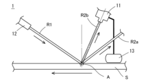
図1は、本実施の形態に係るトッピングゴムシートのゴム付き不良検出装置1(以下、単に「検出装置」ともいう)の構成の概要を示す模式図である。検出装置1は、ラインセンサカメラ11および照射装置12を有する画像データ取得手段と、検出手段(図示せず)とを備えている。そして、Sは、左向き矢印に示すように、紙面上を右から左へと搬送されていくトッピングゴムシートである。なお、13は、トッピングゴムシートSの搬送位置を計測するエンコーダであり、ラインセンサカメラ11と接続されている。また、R1は照射光、R2aは正反射光、R2bは拡散反射光である。
(1) Overall Configuration of the Device Fig. 1 is a schematic diagram showing an outline of the configuration of a topping rubber sheet rubber attachment failure detection device 1 (hereinafter also simply referred to as "detection device") according to this embodiment. The
本実施の形態に係る検出装置1は、搬送されてくるトッピングゴムシートSの画像データを取得する画像データ取得手段、および、取得された画像データを画像処理してトッピングゴムの被覆状態を測定し、ゴム付き不良の発生を検出する検出手段を備えている点においては、従来の装置と基本的には同じであるが、前記したように、画像データ取得手段を構成している照射装置12とラインセンサカメラ11との配置関係が異なっている。
The
(2)画像データ取得手段
画像データ取得手段は、前記したように、照射装置12とラインセンサカメラ11とを備えている。
(2) Image Data Acquisition Means As described above, the image data acquisition means includes the
ラインセンサカメラ11は、連続撮影が可能であるため、ライン速度に影響されることなく、画像データを連続して取得することができる。
The
そして、本実施の形態においては、図1に示すように、画像データ取得手段に、画像データを取得する測定領域Aの位置を計測するエンコーダ13が設けられている。
In this embodiment, as shown in FIG. 1, the image data acquisition means is provided with an
エンコーダ13による位置情報と同期させて、ラインセンサカメラ11による撮影データを取得することにより、画像データの取りこぼしをなくして、ゴム付き不良の発生を安定して検出することができる。
By acquiring the image data from the
そして、照射装置12からトッピングゴムシートSの表面に対して、斜め上方から測定領域Aに向けて所定の角度(入射角)で赤外光を照射すると、照射された照射光R1は、測定領域Aにて反射されて、正反射光R2aや拡散反射光R2bとなる。
Then, when infrared light is irradiated from the
そして、本実施の形態において最も重要なことは、従来の正反射光R2aの延長上ではなく、拡散反射光R2bの延長上にラインセンサカメラ11が配置されており、この拡散反射光R2bをラインセンサカメラ11で受光することにより、画像データが取得されるように、画像データ取得手段を構成させていることである。
And what is most important about this embodiment is that the
これにより、前記したように、テキスタイルシートとトッピングゴムとの間に大きな輝度の差を生じさせた受光ができるため、受光した画像データを画像処理した場合、同じ黒色のテキスタイルシートとトッピングゴムを精度高く区別して、ゴム付き不良の発生を安定して検出することができる。 As a result, as mentioned above, light can be received with a large difference in brightness between the textile sheet and the topping rubber, and when the received image data is processed, the textile sheet and the topping rubber, both of which are the same black color, can be accurately distinguished, enabling stable detection of poor rubber attachment.
なお、トッピングゴムシートの表面へ照射される照射光の入射角が大き過ぎる場合には、照射装置を遠方に配置しないと、トッピングゴムシートと接触してしまう恐れがあるため、小さい入射角に設定されることが好ましいが、小さ過ぎる場合には、照射装置とラインセンサカメラとの間隔が十分に確保できず、互いに接触してしまう恐れがある。 If the angle of incidence of the light irradiated onto the surface of the topping rubber sheet is too large, the irradiation device must be placed far away in order to avoid the risk of contact with the topping rubber sheet. Therefore, it is preferable to set the angle of incidence to a small value. However, if the angle is too small, the distance between the irradiation device and the line sensor camera cannot be sufficiently secured, and there is a risk of them coming into contact with each other.
そして、正反射光R2aに対する拡散反射光R2bの角度が小さ過ぎる場合には、拡散反射光R2bと共に正反射光R2aもラインセンサカメラ11に受光されて、安定した検出ができない恐れがある。一方、角度が大き過ぎる場合には、十分な量の反射光を受光できず、やはり、安定した検出ができない恐れがある。
If the angle of the diffuse reflected light R2b relative to the specular reflected light R2a is too small, the specular reflected light R2a will be received by the
これらの点を考慮すると、本実施の形態において、照射光の具体的に好ましい入射角としては、5~45°が好ましい。 Taking these points into consideration, in this embodiment, the preferred angle of incidence of the irradiated light is 5 to 45°.
また、本実施の形態において、照射光R1の照射源としては、赤外光LEDを用いることが好ましく、その波長としては、850~940nmであることが好ましい。エネルギー効率が高く、高輝度である赤外光LEDを用いて、波長850~940nmの赤外光を照射することにより、トッピングゴムシートの表面における反射の影響を十分に抑制して、安定した検出に適した量の拡散反射光R2bを得ることができる。なお、波長は、870~900nmであるとより好ましい。 In addition, in this embodiment, it is preferable to use an infrared LED as the irradiation source of the irradiation light R1, and the wavelength is preferably 850 to 940 nm. By using an infrared LED that has high energy efficiency and brightness to irradiate infrared light with a wavelength of 850 to 940 nm, the influence of reflection on the surface of the topping rubber sheet can be sufficiently suppressed, and a quantity of diffuse reflected light R2b suitable for stable detection can be obtained. It is more preferable that the wavelength is 870 to 900 nm.
なお、赤外光は、照射装置やラインセンサカメラの表面の汚れの影響を受けにくいという特徴も有している。 Another feature of infrared light is that it is less affected by dirt on the surface of the illumination device or line sensor camera.
また、画像データ取得手段(ラインセンサカメラおよび照射装置)は、トッピングゴムシートの表面から離れた位置に配置されていると、測定領域に対する視野幅が確保できず、また、十分な反射光を得ることが難しくなるため、トッピングゴムシートの表面から近い位置に配置されていることが好ましい。しかし、近過ぎると、搬送されているトッピングゴムシートが接触する恐れがある。具体的には、例えば、ラインセンサカメラについては、トッピングゴムシートの表面から8mm以上で、できるだけ近い位置に配置する一方、照射装置については、対象となるトッピングゴムシートよりも100mm程度幅広の照射装置を、トッピングゴムシートに干渉しない範囲で、できるだけ近い位置に配置することが好ましい。 In addition, if the image data acquisition means (line sensor camera and irradiation device) are placed at a position far from the surface of the topping rubber sheet, the viewing width for the measurement area cannot be secured and it becomes difficult to obtain sufficient reflected light, so it is preferable to place them close to the surface of the topping rubber sheet. However, if they are too close, there is a risk of them coming into contact with the topping rubber sheet being transported. Specifically, for example, the line sensor camera is placed as close as possible to the surface of the topping rubber sheet, but at least 8 mm away, while the irradiation device is preferably placed as close as possible to the target topping rubber sheet, with an irradiation device that is about 100 mm wider than the target topping rubber sheet, without interfering with the topping rubber sheet.
(3)検出手段
検出手段は、上記の画像データ取得手段で取得した画像データを画像処理装置で画像処理することによりゴム付き不良の発生を検出する。
(3) Detecting Means The detecting means detects occurrence of a rubber attachment defect by processing the image data acquired by the image data acquiring means with an image processing device.
具体的には、例えば、濃淡プロブモードによる画像処理を行うことにより得られた画像処理データから、濃黒色部分をテキスタイルシート部分として検出し、その面積を求める。そして、得られたテキスタイルシート部分の面積について、予め、制御装置に組み入れらえている判定基準(閾値)と比較する。 Specifically, for example, from the image processing data obtained by performing image processing in a gray-scale probe mode, the dark black parts are detected as textile sheet parts and their area is calculated. The area of the obtained textile sheet part is then compared with a judgment criterion (threshold value) that is pre-installed in the control device.
比較の結果、閾値以上である場合、ゴム付き不良が発生していると判断して、音や光などの警告出力手段を用いて、作業者に向けて警告信号を発する。このように、本実施の形態においては、ゴム付き不良の発生を自動的に精度高く安定して検出することができるため、作業者の負担も軽減される。 If the result of the comparison is equal to or greater than the threshold, it is determined that a rubber attachment defect has occurred, and a warning signal is issued to the worker using a warning output means such as sound or light. In this way, in this embodiment, the occurrence of a rubber attachment defect can be detected automatically with high accuracy and stability, which reduces the burden on the worker.
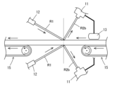
なお、上記では、搬送ラインの上方に検出装置が配置されている場合を例に挙げて説明したが、図2に示すように、トッピングゴムシートを2本の搬送ラインを跨ぐように搬送して、その搬送ラインの間で、トッピングゴムシートの上方、および下方に検出装置を配置して、トッピングゴムシートの両面からゴム付き不良の発生を検出してもよく、これにより、より効率的にゴム付き不良の発生を検出することができる。 In the above, an example was given in which the detection device is located above the conveying line, but as shown in Figure 2, the topping rubber sheet may be conveyed across two conveying lines, and detection devices may be placed above and below the topping rubber sheet between the conveying lines to detect the occurrence of poor rubber attachment from both sides of the topping rubber sheet, thereby making it possible to detect the occurrence of poor rubber attachment more efficiently.
以上、本実施の形態によれば、トッピングゴムシートのように厚みのある材料であっても、黒色のテキスタイルシートとトッピングゴムとを精度高く区別して、テキスタイルシートへのトッピングゴムの被覆状態を知ることにより、ゴム付き不良の発生を安定して検出することができる。 As described above, according to this embodiment, even with a thick material such as a topping rubber sheet, it is possible to accurately distinguish between the black textile sheet and the topping rubber, and by knowing the state of the topping rubber covering the textile sheet, it is possible to stably detect the occurrence of poor rubber attachment.
そして、従来は、次工程まで発見が困難であったゴム付き不良の発生を、トッピングゴムシート製造の段階で発見して適切に対処することができるため、不良ロスの発生の低減や、品質向上へ大きく寄与することができる。 Furthermore, defects in rubber attachment, which were previously difficult to detect until the next process, can now be detected and dealt with appropriately at the topping rubber sheet manufacturing stage, which contributes greatly to reducing defective waste and improving quality.
次に、実施例に基づき本発明をより具体的に説明する。 Next, the present invention will be explained in more detail based on examples.
1.実験方法
(1)装置
ラインセンサカメラ:キーエンス社製のXG-HL04M
(16倍速4000画素ラインセンサカメラ)
レンズ:キーエンス社製のCA-LHW12(ラインセンサカメラ用12mmレンズ)
画像処理装置:キーエンス社製のXG-X2800
照射光源:シーシーエス社製のHLND-1800SW2-RRBC
1. Experimental method (1) Equipment Line sensor camera: Keyence XG-HL04M
(16x speed 4000 pixel line sensor camera)
Lens: Keyence CA-LHW12 (12mm lens for line sensor camera)
Image processing device: Keyence XG-X2800
Irradiation light source: HLND-1800SW2-RRBC manufactured by CCS Corporation
(2)撮影および画像処理条件
ラインセンサカメラおよび照射装置を搬送ラインの上方(鉛直方向)に配置し、トッピングゴムシート表面からの拡散反射光が入光するようにラインセンサカメラを据え付けた。そして、照射装置からトッピングゴムシート表面に波長860nmの赤外光を照射し、拡散反射光をラインセンサカメラで受光して、その撮影画像を画像処理装置に送り込んだ。その後、画像処理装置内において、濃淡プロブモードで画像処理を行った(実施例)。
(2) Photographing and image processing conditions The line sensor camera and the irradiation device were placed above the conveying line (vertically), and the line sensor camera was installed so that the diffuse reflected light from the surface of the topping rubber sheet was incident. Then, the irradiation device irradiated the surface of the topping rubber sheet with infrared light having a wavelength of 860 nm, and the diffuse reflected light was received by the line sensor camera, and the photographed image was sent to the image processing device. After that, image processing was performed in the gray-scale probe mode in the image processing device (Example).
一方、比較のために、ラインセンサカメラを、トッピングゴムシート表面にて正反射した正反射光を受光する位置に据え付け、白色LEDを用いて、照射し、実施例と同様に、ラインセンサカメラで受光した撮影画像を画像処理装置に送り込み、画像処理を行った(比較例)。 On the other hand, for comparison, a line sensor camera was installed in a position to receive the light specularly reflected from the surface of the topping rubber sheet, and was irradiated with a white LED. As in the example, the captured image received by the line sensor camera was sent to an image processing device and subjected to image processing (Comparative Example).
2.実験結果
実施例と比較例で取得された画像データを図3に示す。なお、図3において、右側の画像が実施例、左側の画像が比較例である。
2. Experimental Results Image data obtained in the example and comparative example are shown in Fig. 3. In Fig. 3, the image on the right is the example, and the image on the left is the comparative example.
比較例では、白枠で囲んだ部分がテキスタイルシートの領域であるが、ゴムの領域とテキスタイルシートの領域のいずれもが、同じ濃度の黒色で示されており、区別ができない。 In the comparative example, the area surrounded by a white frame is the textile sheet area, but both the rubber area and the textile sheet area are shown in the same shade of black, making them indistinguishable.
これに対して、実施例では、テキスタイルシートの領域がゴムの領域に比べて、濃い黒色を示しており、明確に両者を区別できることが分かる。 In contrast, in the embodiment, the textile sheet area is a darker black than the rubber area, making it clear that the two can be distinguished.
以上、本発明を実施の形態に基づいて説明したが、本発明は上記の実施の形態に限定されるものではない。本発明と同一および均等の範囲内において、上記の実施の形態に対して種々の変更を加えることができる。 The present invention has been described above based on an embodiment, but the present invention is not limited to the above embodiment. Various modifications can be made to the above embodiment within the same or equivalent scope as the present invention.
1 検出装置
11 ラインセンサカメラ
12 照射装置
13 エンコーダ
15 ベルトコンベア
A 測定領域
S トッピングゴムシート
R1 照射光
R2a 正反射光
R2b 拡散反射光
REFERENCE SIGNS
Claims (6)
前記トッピングゴムシートの表面を撮影して画像データを取得する画像データ取得手段と、
前記画像データ取得手段により取得された画像データを画像処理して、前記トッピングゴムシートにおけるゴム付き不良の発生を検出する検出手段とを備えており、
前記画像データ取得手段は、
前記トッピングゴムシートの表面を連続的に照射する照射装置と、
前記照射装置から照射され、前記トッピングゴムシートの表面で反射した反射光を受光して、画像データを取得するラインセンサカメラとを備えており、
前記反射光の内、拡散反射光が前記ラインセンサカメラに入光するように、前記照射装置と前記ラインセンサカメラとが配置されており、
前記照射装置における照射源が、赤外光LEDであることを特徴とするトッピングゴムシートのゴム付き不良検出装置。 A topping rubber sheet rubber attachment failure detection device for detecting occurrence of a rubber attachment failure in a topping rubber sheet in which a black textile sheet is covered with a black topping rubber, comprising:
An image data acquisition means for acquiring image data by photographing the surface of the topping rubber sheet;
and a detection means for detecting occurrence of a rubber attachment defect in the topping rubber sheet by performing image processing on the image data acquired by the image data acquisition means,
The image data acquisition means includes:
an irradiation device for continuously irradiating the surface of the topping rubber sheet;
a line sensor camera that receives light irradiated from the irradiation device and reflected on the surface of the topping rubber sheet to obtain image data,
the irradiation device and the line sensor camera are disposed so that diffuse reflected light of the reflected light enters the line sensor camera;
A topping rubber sheet rubber attachment defect detection device , characterized in that the irradiation source in the irradiation device is an infrared light LED .
前記ラインセンサカメラによる撮影データを、前記エンコーダによる位置情報と同期させて取得するように構成されていることを特徴とする請求項1ないし請求項3のいずれか1項に記載のトッピングゴムシートのゴム付き不良検出装置。 The image data acquisition means includes an encoder for measuring a conveying position of the topping rubber sheet,
The device for detecting defective rubber attachment of a topping rubber sheet as described in any one of claims 1 to 3 , characterized in that the photographic data captured by the line sensor camera is acquired in synchronization with the positional information captured by the encoder.
前記検出手段が、得られた画像処理データから、濃黒色部分をテキスタイルシート部分として検出することを特徴とする請求項1ないし請求項4のいずれか1項に記載のトッピングゴムシートのゴム付き不良検出装置。 The image processing is image processing in a gray-scale probe mode,
5. The device for detecting defects in rubber attachment of a topping rubber sheet according to claim 1 , wherein the detection means detects a dark black portion as a textile sheet portion from the obtained image processing data.
Priority Applications (1)
| Application Number | Priority Date | Filing Date | Title |
|---|---|---|---|
| JP2021003468A JP7621604B2 (en) | 2021-01-13 | 2021-01-13 | Topping rubber sheet rubber attachment defect detection device |
Applications Claiming Priority (1)
| Application Number | Priority Date | Filing Date | Title |
|---|---|---|---|
| JP2021003468A JP7621604B2 (en) | 2021-01-13 | 2021-01-13 | Topping rubber sheet rubber attachment defect detection device |
Publications (2)
| Publication Number | Publication Date |
|---|---|
| JP2022108461A JP2022108461A (en) | 2022-07-26 |
| JP7621604B2 true JP7621604B2 (en) | 2025-01-27 |
Family
ID=82556539
Family Applications (1)
| Application Number | Title | Priority Date | Filing Date |
|---|---|---|---|
| JP2021003468A Active JP7621604B2 (en) | 2021-01-13 | 2021-01-13 | Topping rubber sheet rubber attachment defect detection device |
Country Status (1)
| Country | Link |
|---|---|
| JP (1) | JP7621604B2 (en) |
Citations (4)
| Publication number | Priority date | Publication date | Assignee | Title |
|---|---|---|---|---|
| JP2003090721A (en) | 2001-09-19 | 2003-03-28 | Bridgestone Corp | Method of detecting rubber member and method of attaching rubber member |
| JP2005537162A (en) | 2002-09-03 | 2005-12-08 | コンチネンタル マボール − インダストリア デ ペネウス、 ソシエダッド アノニマ | Automatic control and monitoring system for splice overlap tolerance in textile ply |
| JP2017003352A (en) | 2015-06-08 | 2017-01-05 | 住友ゴム工業株式会社 | Defect detection device with rubber on topping rubber sheet |
| JP2020101396A (en) | 2018-12-20 | 2020-07-02 | 住友ゴム工業株式会社 | Defect detection device with rubber on topping rubber sheet |
-
2021
- 2021-01-13 JP JP2021003468A patent/JP7621604B2/en active Active
Patent Citations (4)
| Publication number | Priority date | Publication date | Assignee | Title |
|---|---|---|---|---|
| JP2003090721A (en) | 2001-09-19 | 2003-03-28 | Bridgestone Corp | Method of detecting rubber member and method of attaching rubber member |
| JP2005537162A (en) | 2002-09-03 | 2005-12-08 | コンチネンタル マボール − インダストリア デ ペネウス、 ソシエダッド アノニマ | Automatic control and monitoring system for splice overlap tolerance in textile ply |
| JP2017003352A (en) | 2015-06-08 | 2017-01-05 | 住友ゴム工業株式会社 | Defect detection device with rubber on topping rubber sheet |
| JP2020101396A (en) | 2018-12-20 | 2020-07-02 | 住友ゴム工業株式会社 | Defect detection device with rubber on topping rubber sheet |
Also Published As
| Publication number | Publication date |
|---|---|
| JP2022108461A (en) | 2022-07-26 |
Similar Documents
| Publication | Publication Date | Title |
|---|---|---|
| JP3754003B2 (en) | Defect inspection apparatus and method | |
| CN111426696B (en) | Rubber adhesion failure detection device for top covering rubber sheet | |
| CN100448655C (en) | Automatic Control and Monitoring System of Splice Lap Tolerance in Textile Cord | |
| CN110402386B (en) | Cylindrical surface inspection device and cylindrical surface inspection method | |
| TW201937161A (en) | Apparatus and method for inspecting a glass sheet | |
| KR20240067222A (en) | Device for measuring irregularities in sheet-shaped objects, method for measuring irregularities in sheet-shaped objects | |
| JP6699694B2 (en) | Inspection system, inspection method | |
| TWI786522B (en) | Surface inspection device, surface inspection method, steel manufacturing method, steel quality control method, and steel manufacturing equipment | |
| JPH08271433A (en) | Tablet inspection device | |
| KR20090053677A (en) | Pattern checker | |
| JP7621604B2 (en) | Topping rubber sheet rubber attachment defect detection device | |
| JP2017003352A (en) | Defect detection device with rubber on topping rubber sheet | |
| CN116056806B (en) | Method for manufacturing sheet member | |
| JP3870140B2 (en) | Driving transmission belt inspection method | |
| JP7699755B2 (en) | Topping rubber sheet rubber attachment defect detection device | |
| CN120659987A (en) | Inspection apparatus | |
| JP6428554B2 (en) | Inspection system, inspection method | |
| JP2005351825A (en) | Defect inspection device | |
| JP2003344299A (en) | Color filter defect inspection apparatus and color filter defect inspection method | |
| JP4023295B2 (en) | Surface inspection method and surface inspection apparatus | |
| JP2009229173A (en) | Device and method for inspecting uncoated part of thin film coating | |
| JP2000081396A (en) | Automatic quality determination method and apparatus for winding roll side surface | |
| JP2012013586A (en) | Automatic egg inspection mechanism by image processing | |
| JPH06288934A (en) | Method for detecting edge defect of hot rolled sheet | |
| JP7524717B2 (en) | Inspection Equipment |
Legal Events
| Date | Code | Title | Description |
|---|---|---|---|
| A621 | Written request for application examination |
Free format text: JAPANESE INTERMEDIATE CODE: A621 Effective date: 20231121 |
|
| A977 | Report on retrieval |
Free format text: JAPANESE INTERMEDIATE CODE: A971007 Effective date: 20240621 |
|
| A131 | Notification of reasons for refusal |
Free format text: JAPANESE INTERMEDIATE CODE: A131 Effective date: 20240716 |
|
| A521 | Request for written amendment filed |
Free format text: JAPANESE INTERMEDIATE CODE: A523 Effective date: 20240912 |
|
| TRDD | Decision of grant or rejection written | ||
| A01 | Written decision to grant a patent or to grant a registration (utility model) |
Free format text: JAPANESE INTERMEDIATE CODE: A01 Effective date: 20241216 |
|
| A61 | First payment of annual fees (during grant procedure) |
Free format text: JAPANESE INTERMEDIATE CODE: A61 Effective date: 20241229 |
|
| R150 | Certificate of patent or registration of utility model |
Ref document number: 7621604 Country of ref document: JP Free format text: JAPANESE INTERMEDIATE CODE: R150 |