JP7613232B2 - Parts disassembly device and control method for the parts disassembly device - Google Patents

Parts disassembly device and control method for the parts disassembly device Download PDF

Info

Publication number
JP7613232B2
JP7613232B2 JP2021072399A JP2021072399A JP7613232B2 JP 7613232 B2 JP7613232 B2 JP 7613232B2 JP 2021072399 A JP2021072399 A JP 2021072399A JP 2021072399 A JP2021072399 A JP 2021072399A JP 7613232 B2 JP7613232 B2 JP 7613232B2
Authority
JP
Japan
Prior art keywords
motor
motors
mounting surface
disassembly device
rotation
Prior art date
Legal status (The legal status is an assumption and is not a legal conclusion. Google has not performed a legal analysis and makes no representation as to the accuracy of the status listed.)
Active
Application number
JP2021072399A
Other languages
Japanese (ja)
Other versions
JP2022166945A (en
Inventor
孝典 鈴木
和史 大谷
正輝 宮坂
正一 小林
Current Assignee (The listed assignees may be inaccurate. Google has not performed a legal analysis and makes no representation or warranty as to the accuracy of the list.)
Seiko Epson Corp
Original Assignee
Seiko Epson Corp
Priority date (The priority date is an assumption and is not a legal conclusion. Google has not performed a legal analysis and makes no representation as to the accuracy of the date listed.)
Filing date
Publication date
Application filed by Seiko Epson Corp filed Critical Seiko Epson Corp
Priority to JP2021072399A priority Critical patent/JP7613232B2/en
Priority to CN202210417027.5A priority patent/CN115229845B/en
Priority to CN202510881333.8A priority patent/CN120715948A/en
Publication of JP2022166945A publication Critical patent/JP2022166945A/en
Application granted granted Critical
Publication of JP7613232B2 publication Critical patent/JP7613232B2/en
Active legal-status Critical Current
Anticipated expiration legal-status Critical

Links

Images

Classifications

    • BPERFORMING OPERATIONS; TRANSPORTING
    • B25HAND TOOLS; PORTABLE POWER-DRIVEN TOOLS; MANIPULATORS
    • B25JMANIPULATORS; CHAMBERS PROVIDED WITH MANIPULATION DEVICES
    • B25J19/00Accessories fitted to manipulators, e.g. for monitoring, for viewing; Safety devices combined with or specially adapted for use in connection with manipulators
    • BPERFORMING OPERATIONS; TRANSPORTING
    • B23MACHINE TOOLS; METAL-WORKING NOT OTHERWISE PROVIDED FOR
    • B23PMETAL-WORKING NOT OTHERWISE PROVIDED FOR; COMBINED OPERATIONS; UNIVERSAL MACHINE TOOLS
    • B23P19/00Machines for simply fitting together or separating metal parts or objects, or metal and non-metal parts, whether or not involving some deformation; Tools or devices therefor so far as not provided for in other classes
    • BPERFORMING OPERATIONS; TRANSPORTING
    • B25HAND TOOLS; PORTABLE POWER-DRIVEN TOOLS; MANIPULATORS
    • B25JMANIPULATORS; CHAMBERS PROVIDED WITH MANIPULATION DEVICES
    • B25J9/00Programme-controlled manipulators
    • B25J9/16Programme controls
    • B25J9/1602Programme controls characterised by the control system, structure, architecture
    • BPERFORMING OPERATIONS; TRANSPORTING
    • B25HAND TOOLS; PORTABLE POWER-DRIVEN TOOLS; MANIPULATORS
    • B25JMANIPULATORS; CHAMBERS PROVIDED WITH MANIPULATION DEVICES
    • B25J9/00Programme-controlled manipulators
    • B25J9/16Programme controls
    • B25J9/1694Programme controls characterised by use of sensors other than normal servo-feedback from position, speed or acceleration sensors, perception control, multi-sensor controlled systems, sensor fusion
    • B25J9/1697Vision controlled systems

Landscapes

  • Engineering & Computer Science (AREA)
  • Mechanical Engineering (AREA)
  • Robotics (AREA)
  • Automation & Control Theory (AREA)
  • Automatic Assembly (AREA)
  • Manipulator (AREA)
  • Jigging Conveyors (AREA)
  • Feeding Of Articles To Conveyors (AREA)
  • Apparatuses For Generation Of Mechanical Vibrations (AREA)
  • Connection Of Motors, Electrical Generators, Mechanical Devices, And The Like (AREA)
  • Mixers With Rotating Receptacles And Mixers With Vibration Mechanisms (AREA)

Description

本発明は、部品バラシ装置および部品バラシ装置の制御方法に関するものである。 The present invention relates to a part disassembly device and a control method for the part disassembly device.

工業用ロボットが部品をピックアンドプレースするときに、ロボットハンドの動作範囲内でリニアフィーダーが部品を移動する。このリニアフィーダーが特許文献1に開示されている。それによると、リニアフィーダーでは1台のモーターと部品搬送トラフとがリンク機構で接続されていた。モーターを回転させるとき、部品搬送トラフに1方向の往復振動が励起され、部品が1方向に搬送された。 When an industrial robot picks and places a part, a linear feeder moves the part within the range of motion of the robot hand. This linear feeder is disclosed in Patent Document 1. According to this, in the linear feeder, one motor and a part transport trough are connected by a link mechanism. When the motor is rotated, a reciprocating vibration in one direction is excited in the part transport trough, and the part is transported in one direction.

ロボットハンドの動作範囲内に部品バラシ装置を配置することがある。部品バラシ装置は複数の部品が載置面上で重なっているときに、各部品の重なりを少なくする装置である。 A part disassembly device may be placed within the operating range of the robot hand. The part disassembly device is a device that reduces the overlap of parts when multiple parts are stacked on the placement surface.

ロボットハンドは部品を取りやすい場所と取り難い場所とがある。従って、ロボットが取りやすい場所に部品を移動させる装置があると、ロボットは安定して稼働できる。また、ロボットに部品を反転させる作業を行わせると、作業に時間がかかるので、生産性が低下する。 There are places where it is easy for a robot hand to pick up parts and places where it is difficult. Therefore, if there is a device that moves parts to places where the robot can easily pick them up, the robot can operate stably. Also, if a robot is made to flip parts, the work takes time, which reduces productivity.

特開2019-64825号公報JP 2019-64825 A

特許文献1のリニアフィーダーは一方向にしか部品を移動できない。また、部品を反転することもできないという課題があった。 The linear feeder in Patent Document 1 can only move parts in one direction. It also has the problem that it cannot flip parts over.

部品バラシ装置は、部品が載置される載置面を有する載置台と、回転軸を回転させて振動する3つのモーターと、前記載置台及び3つの前記モーターを支持し、前記モーターの振動を前記載置台に伝達する支持部と、を備え、1つの前記モーターの前記回転軸の軸方向が前記載置面に平行で、且つ、2つの前記モーターの前記回転軸の軸方向が前記載置面に対して垂直である。 The part disassembly device includes a mounting table having a mounting surface on which parts are placed, three motors that vibrate by rotating their rotation shafts, and a support section that supports the mounting table and the three motors and transmits the vibrations of the motors to the mounting table, with the axial direction of the rotation shaft of one of the motors being parallel to the mounting surface, and the axial directions of the rotation shafts of the two motors being perpendicular to the mounting surface.

部品バラシ装置の制御方法は、部品が載置される載置面を有する載置台と、回転軸を回転させて振動する3つのモーターと、前記載置台及び3つの前記モーターを支持し、前記モーターの振動を前記載置台に伝達する支持部と、前記モーターの回転を制御する制御部と、を備え、1つの前記モーターの前記回転軸の軸方向が前記載置面に平行で、且つ、2つの前記モーターの前記回転軸の軸方向が前記載置面に対して垂直である部品バラシ装置の制御方法であって、前記制御部は3つの前記モーターの回転数、回転方向、初期位相の少なくとも一つを独立して制御する。 A control method for a part disassembly device comprising a mounting table having a mounting surface on which parts are placed, three motors that vibrate by rotating their rotation shafts, a support section that supports the mounting table and the three motors and transmits the vibrations of the motors to the mounting table, and a control section that controls the rotation of the motors, in which the axial direction of the rotation shaft of one of the motors is parallel to the mounting surface and the axial directions of the rotation shafts of two of the motors are perpendicular to the mounting surface, and the control section independently controls at least one of the rotation speed, rotation direction, and initial phase of the three motors.

第1実施形態にかかわるロボット組立てシステムの構成を示す概略図。1 is a schematic diagram showing a configuration of a robot assembly system according to a first embodiment. 部品バラシ装置の構成を示す概略斜視図。FIG. 2 is a schematic perspective view showing the configuration of a part disassembly device. 部品バラシ装置の構成を示す模式平面図。FIG. 2 is a schematic plan view showing the configuration of the part disassembly device. 部品バラシ装置の構成を示す模式側面図。FIG. 2 is a schematic side view showing the configuration of the part disassembly device. 部品バラシ装置の構成を示す模式側面図。FIG. 2 is a schematic side view showing the configuration of the part disassembly device. モーターの配置を説明するための要部概略斜視図。FIG. 4 is a schematic perspective view of a main portion for explaining the arrangement of a motor. ゴム脚の配置を説明するための模式平面図。FIG. 4 is a schematic plan view illustrating the arrangement of rubber legs. 電気回路のブロック図。Block diagram of an electrical circuit. モーターの動きを説明するための模式図。Schematic diagram for explaining the movement of a motor. 部品バラシ装置の動きを説明するための模式側面図。FIG. 4 is a schematic side view for explaining the movement of the part disassembly device. 部品バラシ装置の動きを説明するための模式側面図。FIG. 4 is a schematic side view for explaining the movement of the part disassembly device. 載置面上の部品の動きを説明するための模式平面図。FIG. 4 is a schematic plan view for explaining the movement of a component on a placement surface. 載置面上の部品の動きを説明するための模式平面図。FIG. 4 is a schematic plan view for explaining the movement of a component on a placement surface. モーターの動きを説明するための模式図。Schematic diagram for explaining the movement of a motor. 載置面上の部品の動きを説明するための模式平面図。FIG. 4 is a schematic plan view for explaining the movement of a component on a placement surface. 載置面上の部品の動きを説明するための模式平面図。FIG. 4 is a schematic plan view for explaining the movement of a component on a placement surface. 載置台の動きを説明するための模式図。FIG. 4 is a schematic diagram for explaining the movement of the mounting table. 載置面上の部品の動きを説明するための模式平面図。FIG. 4 is a schematic plan view for explaining the movement of a component on a placement surface. 載置台の動きを説明するための模式図。FIG. 4 is a schematic diagram for explaining the movement of the mounting table. 載置面上の部品の動きを説明するための模式平面図。FIG. 4 is a schematic plan view for explaining the movement of a component on a placement surface. 載置台の動きを説明するための模式図。FIG. 4 is a schematic diagram for explaining the movement of the mounting table. 載置面上の部品の動きを説明するための模式平面図。FIG. 4 is a schematic plan view for explaining the movement of a component on a placement surface.

第1実施形態
本実施形態では、部品バラシ装置と、部品バラシ装置の制御方法との特徴的な例について説明する。図1に示すように、ロボット組立てシステム1はロボット2が複数の部品を組み立てるシステムである。ロボット2にはスカラーロボット、垂直多関節ロボット、直交ロボット等が用いられる。ロボット2はロボットコントローラー3を備える。ロボットコントローラー3はロボット2の姿勢を制御する。
First Embodiment In this embodiment, a characteristic example of a part disassembly device and a control method for the part disassembly device will be described. As shown in Fig. 1, a robot assembly system 1 is a system in which a robot 2 assembles a plurality of parts. A scalar robot, a vertical articulated robot, an orthogonal robot, or the like is used as the robot 2. The robot 2 is equipped with a robot controller 3. The robot controller 3 controls the posture of the robot 2.

ロボット2はアクチュエーター4及びカメラ5を備える。ロボットコントローラー3はアクチュエーター4の動作を制御して部品を把持する。ロボットコントローラー3はカメラ5に部品を撮像させて、部品の位置を認識する。尚、カメラ5は、部品バラシ装置6の上に設置されていてもよい。 The robot 2 is equipped with an actuator 4 and a camera 5. The robot controller 3 controls the operation of the actuator 4 to grasp the part. The robot controller 3 causes the camera 5 to capture an image of the part and recognize the position of the part. The camera 5 may be installed on the part disassembly device 6.

ロボット組立てシステム1は複数の部品バラシ装置6及び作業台7を備える。各部品バラシ装置6にはそれぞれ部品が載置される。ロボット2は各部品バラシ装置6の部品を把持して作業台7に移動する。ロボット2は作業台7にて部品を組み立てる作業をする。 The robot assembly system 1 is equipped with multiple part disassembly devices 6 and a workbench 7. Parts are placed on each part disassembly device 6. The robot 2 grasps a part from each part disassembly device 6 and moves it to the workbench 7. The robot 2 works to assemble the parts on the workbench 7.

各部品バラシ装置6はそれぞれ制御部8を備える。各制御部8は部品バラシ装置6及びロボットコントローラー3と電気的に接続される。制御部8はロボットコントローラー3から指示信号を入力して、部品バラシ装置6を作動させる。 Each part disassembly device 6 is equipped with a control unit 8. Each control unit 8 is electrically connected to the part disassembly device 6 and the robot controller 3. The control unit 8 inputs an instruction signal from the robot controller 3 to operate the part disassembly device 6.

カメラ5が部品バラシ装置6に載置された部品を撮影する。ロボットコントローラー3は撮影された画像を解析して、アクチュエーター4が部品を把持し易い状態であるか否かを判定する。また、アクチュエーター4が把持するときの部品の向きが設定されている。例えば、本実施形態では、部品が円板状であり、表裏の区別がある。本実施形態では部品の表側がアクチュエーター4を向く状態でアクチュエーター4が部品を把持することとする。 The camera 5 captures an image of a part placed on the part disassembly device 6. The robot controller 3 analyzes the captured image and determines whether the actuator 4 is in a state where it is easy to grasp the part. The orientation of the part when grasped by the actuator 4 is also set. For example, in this embodiment, the part is disk-shaped and has a front and back. In this embodiment, the actuator 4 grasps the part with the front side facing the actuator 4.

ロボットコントローラー3が画像を解析した結果、部品の姿勢が適正な姿勢でないとき、ロボットコントローラー3が制御部8に部品の姿勢を変える指示信号を送信する。制御部8は指示信号を受信して部品バラシ装置6を駆動する。 When the robot controller 3 analyzes the image and finds that the part is not in the correct position, the robot controller 3 sends an instruction signal to the control unit 8 to change the part's position. The control unit 8 receives the instruction signal and drives the part disassembly device 6.

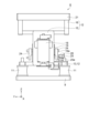
図2に示す部品バラシ装置6はカバーが外されており、内部が見えるようになっている。部品バラシ装置6は基台9を備える。基台9は長方形の金属板である。基台9の平面視で長手方向をX方向とし、長手方向と直交する方向をY方向とする。基台9の厚み方向をZ方向とする。 The cover of the part disassembly device 6 shown in Figure 2 has been removed so that the inside can be seen. The part disassembly device 6 is equipped with a base 9. The base 9 is a rectangular metal plate. When viewed from above, the longitudinal direction of the base 9 is the X direction, and the direction perpendicular to the longitudinal direction is the Y direction. The thickness direction of the base 9 is the Z direction.

基台9上には4つのゴムとしてのゴム脚11が配置される。ゴム脚11上には支持部12が設置される。ゴム脚11は支持部12を振動可能に支持する。この構成によれば、ゴム脚11が支持部12を振動可能に支持することから、支持部12は上下前後左右のすべての方向に振動することができる。また、ゴム脚11は振動を減衰させるので、ゴム脚11をダンパーとして機能させることができる。 Four rubber feet 11 are arranged on the base 9. A support portion 12 is placed on the rubber feet 11. The rubber feet 11 support the support portion 12 so that it can vibrate. With this configuration, the rubber feet 11 support the support portion 12 so that it can vibrate, allowing the support portion 12 to vibrate in all directions: up and down, front and back, left and right. In addition, the rubber feet 11 dampen vibrations, allowing the rubber feet 11 to function as dampers.

支持部12は下部構造体13、第1中間構造体14、第2中間構造体15及び上部構造体16にて構成される。下部構造体13はZ負方向側に位置し、ゴム脚11と接続する。上部構造体16はZ正方向側に位置する。第1中間構造体14及び第2中間構造体15は板状であり、第1中間構造体14及び第2中間構造体15が下部構造体13と上部構造体16との間で立脚する。第1中間構造体14及び第2中間構造体15は下部構造体13及び上部構造体16を固定する。支持部12の材質は金属であり、支持部12は剛性が高い。 The support part 12 is composed of a lower structure 13, a first intermediate structure 14, a second intermediate structure 15, and an upper structure 16. The lower structure 13 is located on the negative Z direction side and is connected to the rubber foot 11. The upper structure 16 is located on the positive Z direction side. The first intermediate structure 14 and the second intermediate structure 15 are plate-shaped, and the first intermediate structure 14 and the second intermediate structure 15 stand between the lower structure 13 and the upper structure 16. The first intermediate structure 14 and the second intermediate structure 15 fix the lower structure 13 and the upper structure 16. The support part 12 is made of metal, and has high rigidity.

下部構造体13と上部構造体16との間にはモーターとしての第1モーター17、モーターとしての第2モーター18及びモーターとしての第3モーター19が配置される。制御部8は第1モーター17、第2モーター18及び第3モーター19の回転を制御する。第1モーター17は第1中間構造体14のX正方向側の面に固定される。第2モーター18は第2中間構造体15のX負方向側の面に固定される。第3モーター19は下部構造体13のZ正方向側の面に固定される。 A first motor 17, a second motor 18, and a third motor 19 are arranged between the lower structure 13 and the upper structure 16. The control unit 8 controls the rotation of the first motor 17, the second motor 18, and the third motor 19. The first motor 17 is fixed to the surface of the first intermediate structure 14 on the positive X direction side. The second motor 18 is fixed to the surface of the second intermediate structure 15 on the negative X direction side. The third motor 19 is fixed to the surface of the lower structure 13 on the positive Z direction side.

上部構造体16のZ正方向側には載置台21が配置される。載置台21は上部構造体16に固定される。載置台21の材質は金属であり、載置台21は剛性が高い。載置台21はZ正方向側に凹部21aが形成される。凹部21aの底面が載置面22である。尚、載置台21の材質は樹脂でもよい。 A mounting table 21 is disposed on the Z positive side of the upper structure 16. The mounting table 21 is fixed to the upper structure 16. The mounting table 21 is made of a metal material, and has high rigidity. A recess 21a is formed on the Z positive side of the mounting table 21. The bottom surface of the recess 21a is the mounting surface 22. The material of the mounting table 21 may be resin.

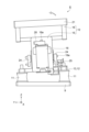
図3に示すように、載置面22には部品23が載置される。載置台21は部品23が載置される載置面22を有する。部品23の幾つかは表側23aがZ正方向側を向く。部品23の幾つかは裏側23bがZ正方向側を向く。図中では裏側23bがZ正方向側を向く部品23にハッチングが施されている。部品23は凹部21aの中に載置されており、部品23は凹部21aの外に出難くなっている。 As shown in FIG. 3, components 23 are placed on the placement surface 22. The placement table 21 has the placement surface 22 on which the components 23 are placed. The front sides 23a of some of the components 23 face in the positive Z direction. The back sides 23b of some of the components 23 face in the positive Z direction. In the figure, the components 23 whose back sides 23b face in the positive Z direction are hatched. The components 23 are placed in the recesses 21a, making it difficult for the components 23 to come out of the recesses 21a.

図4及び図5に示すように、第3モーター19は回転軸としての第3回転軸19aに対して偏心する偏心重りとしての第3偏心重り24を第3回転軸19aに備える。この構成によれば、第3偏心重り24は簡単な構造で第3モーター19を振動させることができる。第3モーター19の振動は支持部12を介して載置台21に伝達される。 As shown in Figures 4 and 5, the third motor 19 is provided with a third eccentric weight 24 on the third rotating shaft 19a as an eccentric weight that is eccentric with respect to the third rotating shaft 19a as a rotating shaft. With this configuration, the third eccentric weight 24 can vibrate the third motor 19 with a simple structure. The vibration of the third motor 19 is transmitted to the mounting table 21 via the support part 12.

第3モーター19は第3回転軸19aの両側に第3偏心重り24を備える。この構成によれば、第3偏心重り24の回転により第3回転軸19aの両側で同じ遠心力が第3モーター19に作用する。従って、第3回転軸19aの両側が同じ振動エネルギーを支持部12に供給できる。その結果、X方向を軸として支持部12が揺動する振動を第3モーター19が生じさせることを抑制できる。Y負方向側の第3偏心重り24のY負方向側では下部構造体13上に第3センサー25が配置される。 The third motor 19 is equipped with a third eccentric weight 24 on both sides of the third rotating shaft 19a. With this configuration, the rotation of the third eccentric weight 24 causes the same centrifugal force to act on the third motor 19 on both sides of the third rotating shaft 19a. Therefore, both sides of the third rotating shaft 19a can supply the same vibration energy to the support part 12. As a result, it is possible to suppress the third motor 19 from generating vibrations that cause the support part 12 to swing around the X direction as an axis. A third sensor 25 is disposed on the lower structure 13 on the Y negative side of the third eccentric weight 24 on the Y negative side.

載置面22と垂直な方向から見るとき、載置面22の中心と2つの第3偏心重り24の重心とが重なる。従って、第3モーター19は載置面22を一様に振動させることができる。 When viewed from a direction perpendicular to the support surface 22, the center of the support surface 22 overlaps with the center of gravity of the two third eccentric weights 24. Therefore, the third motor 19 can vibrate the support surface 22 uniformly.

第3モーター19と接続するY負方向側の第3偏心重り24はY負方向側に突出する第3凸部26を備える。第3センサー25は第3スリット25aを備える。第3センサー25には第3スリット25aを挟んでLED(Light Emitting Diode)及びフォトトランジスターが配置される。第3凸部26が第3スリット25aを通過するとき、LEDが発する光を第3凸部26が遮断する。第3凸部26が第3スリット25aを通過するタイミングを第3センサー25が検出する。 The third eccentric weight 24 on the negative Y direction side connected to the third motor 19 has a third convex portion 26 that protrudes toward the negative Y direction side. The third sensor 25 has a third slit 25a. The third sensor 25 has an LED (Light Emitting Diode) and a phototransistor arranged on either side of the third slit 25a. When the third convex portion 26 passes through the third slit 25a, the third convex portion 26 blocks the light emitted by the LED. The third sensor 25 detects the timing when the third convex portion 26 passes through the third slit 25a.

図6は第1モーター17、第2モーター18及び第3モーター19の相対位置を示す。図4及び図6に示すように、第1モーター17は回転軸としての第1回転軸17aに対して偏心する偏心重りとしての第1偏心重り27を第1回転軸17aに備える。第2モーター18は回転軸としての第2回転軸18aに対して偏心する偏心重りとしての第2偏心重り28を第2回転軸18aに備える。この構成によれば、第1偏心重り27は簡単な構造で第1モーター17を振動させることができる。第2偏心重り28は簡単な構造で第2モーター18を振動させることができる。第1モーター17及び第2モーター18の振動は支持部12を介して載置台21に伝達される。 Figure 6 shows the relative positions of the first motor 17, the second motor 18, and the third motor 19. As shown in Figures 4 and 6, the first motor 17 is provided with a first eccentric weight 27 on the first rotating shaft 17a as an eccentric weight that is eccentric with respect to the first rotating shaft 17a as a rotating shaft. The second motor 18 is provided with a second eccentric weight 28 on the second rotating shaft 18a as an eccentric weight that is eccentric with respect to the second rotating shaft 18a as a rotating shaft. With this configuration, the first eccentric weight 27 can vibrate the first motor 17 with a simple structure. The second eccentric weight 28 can vibrate the second motor 18 with a simple structure. The vibrations of the first motor 17 and the second motor 18 are transmitted to the mounting table 21 via the support part 12.

部品バラシ装置6は第1回転軸17aを回転させて振動する第1モーター17、第2回転軸18aを回転させて振動する第2モーター18及び第3回転軸19aを回転させて振動する第3モーター19を備える。支持部12は載置台21、第1モーター17、第2モーター18及び第3モーター19を支持し、第1モーター17、第2モーター18及び第3モーター19の振動を載置台21に伝達する。支持部12の共振周波数は載置面22と平行な方向よりも垂直な方向が高くなっている。 The part disassembly device 6 includes a first motor 17 that vibrates by rotating a first rotating shaft 17a, a second motor 18 that vibrates by rotating a second rotating shaft 18a, and a third motor 19 that vibrates by rotating a third rotating shaft 19a. The support portion 12 supports the mounting table 21, the first motor 17, the second motor 18, and the third motor 19, and transmits the vibrations of the first motor 17, the second motor 18, and the third motor 19 to the mounting table 21. The resonant frequency of the support portion 12 is higher in a direction perpendicular to the mounting surface 22 than in a direction parallel to the mounting surface 22.

図6に示すように、第1回転軸17a及び第2回転軸18aの軸方向はZ方向であり、第3回転軸19aの軸方向はY方向である。載置面22はX方向及びY方向を含む平面である。Z方向は載置面22に対して垂直な方向である。第3モーター19の第3回転軸19aの軸方向が載置面22に平行で、第1モーター17の第1回転軸17aの軸方向及び第2モーター18の第2回転軸18aの軸方向は載置面22に対して垂直である。従って、部品バラシ装置6では1つのモーターの回転軸の軸方向が載置面22に平行で、且つ、2つのモーターの回転軸の軸方向が載置面22に対して垂直である。 As shown in FIG. 6, the axial direction of the first and second rotating shafts 17a and 18a is the Z direction, and the axial direction of the third rotating shaft 19a is the Y direction. The mounting surface 22 is a plane including the X and Y directions. The Z direction is perpendicular to the mounting surface 22. The axial direction of the third rotating shaft 19a of the third motor 19 is parallel to the mounting surface 22, and the axial direction of the first rotating shaft 17a of the first motor 17 and the second rotating shaft 18a of the second motor 18 are perpendicular to the mounting surface 22. Therefore, in the part disassembly device 6, the axial direction of the rotation shaft of one motor is parallel to the mounting surface 22, and the axial directions of the rotation shafts of the two motors are perpendicular to the mounting surface 22.

載置面22と垂直な方向から見るとき、第3回転軸19aの軸方向が載置面22に平行な第3モーター19は回転軸の軸方向が載置面22に対して垂直である第1モーター17と第2モーター18との間に配置される。 When viewed from a direction perpendicular to the mounting surface 22, the third motor 19, whose third rotating shaft 19a has an axial direction parallel to the mounting surface 22, is disposed between the first motor 17 and the second motor 18, whose rotating shaft axial directions are perpendicular to the mounting surface 22.

この構成によれば、3つのモーターが並んで配置される。中央の第3モーター19は載置面22に対して垂直な方向に載置台21を振動させる。第3モーター19の外側に配置される第1モーター17及び第2モーター18は載置面22に対して平行な方向に載置台21を振動させる。第1モーター17及び第2モーター18の重心は中央の第3モーター19の第3回転軸19aに対して対称的に配置される。従って、両側の2つのモーターが回転軸を回転させるとき、モーターの振動は一様に載置台21を振動させることができる。 According to this configuration, three motors are arranged side by side. The central third motor 19 vibrates the mounting table 21 in a direction perpendicular to the mounting surface 22. The first motor 17 and the second motor 18 arranged outside the third motor 19 vibrate the mounting table 21 in a direction parallel to the mounting surface 22. The centers of gravity of the first motor 17 and the second motor 18 are arranged symmetrically with respect to the third rotation shaft 19a of the central third motor 19. Therefore, when the two motors on both sides rotate the rotation shafts, the vibration of the motors can uniformly vibrate the mounting table 21.

第1モーター17のZ負方向側では第1回転軸17aに第1回転板29が取り付けられる。第1回転板29には半径方向に長いスリットである第1円板スリット29aが設けられる。第1モーター17のZ負方向側には第1センサー31が設けられる。第1センサー31は下部構造体13に固定される。第1センサー31は第1センサースリット31aを備える。第1センサー31には第1センサースリット31aを挟んでLED及びフォトトランジスターが配置される。第1円板スリット29aが第1センサースリット31aを通過するとき、LEDが発する光が第1円板スリット29aを通過する。第1円板スリット29aが第1センサースリット31aを通過するタイミングを第1センサー31が検出する。 A first rotating plate 29 is attached to the first rotating shaft 17a on the Z negative side of the first motor 17. A first disk slit 29a, which is a long slit in the radial direction, is provided on the first rotating plate 29. A first sensor 31 is provided on the Z negative side of the first motor 17. The first sensor 31 is fixed to the lower structure 13. The first sensor 31 has a first sensor slit 31a. An LED and a phototransistor are arranged on either side of the first sensor slit 31a in the first sensor 31. When the first disk slit 29a passes through the first sensor slit 31a, light emitted by the LED passes through the first disk slit 29a. The first sensor 31 detects the timing at which the first disk slit 29a passes through the first sensor slit 31a.

第2モーター18のZ負方向側では第2回転軸18aに第2回転板32が取り付けられる。第2回転板32には半径方向に長いスリットである第2円板スリット32aが設けられる。第2モーター18のZ負方向側には第2センサー33が設けられる。第2センサー33は下部構造体13に固定される。第2センサー33は第2センサースリット33aを備える。第2センサー33には第2センサースリット33aを挟んでLED及びフォトトランジスターが配置される。第2円板スリット32aが第2センサースリット33aを通過するとき、LEDが発する光が第2円板スリット32aを通過する。第2円板スリット32aが第2センサースリット33aを通過するタイミングを第2センサー33が検出する。 A second rotating plate 32 is attached to the second rotating shaft 18a on the Z negative side of the second motor 18. A second disk slit 32a, which is a long slit in the radial direction, is provided on the second rotating plate 32. A second sensor 33 is provided on the Z negative side of the second motor 18. The second sensor 33 is fixed to the lower structure 13. The second sensor 33 has a second sensor slit 33a. An LED and a phototransistor are arranged on either side of the second sensor slit 33a on the second sensor 33. When the second disk slit 32a passes through the second sensor slit 33a, light emitted by the LED passes through the second disk slit 32a. The second sensor 33 detects the timing at which the second disk slit 32a passes through the second sensor slit 33a.

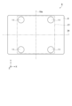
図7はゴム脚11の配置を示す。図7に示すように、基台9にはゴム脚11が4つ配置される。ゴム脚11は第3回転軸19aに対して対称に配置される。第1回転軸17aのZ正方向の端と第2回転軸18aのZ正方向の端とを通る仮想線34に対してゴム脚11は対称に配置される。この配置にすることで支持部12のX方向の共振周波数とY方向の共振周波数との設計が容易になる。 Figure 7 shows the arrangement of the rubber feet 11. As shown in Figure 7, four rubber feet 11 are arranged on the base 9. The rubber feet 11 are arranged symmetrically with respect to the third rotation shaft 19a. The rubber feet 11 are arranged symmetrically with respect to an imaginary line 34 that passes through the Z positive end of the first rotation shaft 17a and the Z positive end of the second rotation shaft 18a. This arrangement makes it easier to design the X-direction resonance frequency and Y-direction resonance frequency of the support part 12.

図8に示すように、制御部8は中央演算部35、第1モーター駆動部36、第2モーター駆動部37及び第3モーター駆動部38を備える。中央演算部35は、ロボットコントローラー3、第1モーター駆動部36、第2モーター駆動部37及び第3モーター駆動部38と電気的に接続される。中央演算部35は第1モーター駆動部36、第2モーター駆動部37及び第3モーター駆動部38に回転開始及び回転終了の指示信号を送信する。他にも、中央演算部35は第1モーター駆動部36、第2モーター駆動部37及び第3モーター駆動部38に回転数、回転方向及び位相の指示信号を送信する。 As shown in FIG. 8, the control unit 8 includes a central processing unit 35, a first motor driving unit 36, a second motor driving unit 37, and a third motor driving unit 38. The central processing unit 35 is electrically connected to the robot controller 3, the first motor driving unit 36, the second motor driving unit 37, and the third motor driving unit 38. The central processing unit 35 transmits instruction signals for starting and ending rotation to the first motor driving unit 36, the second motor driving unit 37, and the third motor driving unit 38. The central processing unit 35 also transmits instruction signals for the number of rotations, the direction of rotation, and the phase to the first motor driving unit 36, the second motor driving unit 37, and the third motor driving unit 38.

第1モーター駆動部36は第1モーター17及び第1センサー31と電気的に接続される。第1モーター17を駆動するとき、第1モーター駆動部36は指示信号に示された回転数及び回転方向に従って、第1モーター17を駆動する。第1センサー31が検出する第1回転軸17aの位置を示す信号を第1モーター駆動部36が入力する。第1モーター駆動部36は第1センサー31が出力する信号を入力して、第1回転軸17aの回転数が指示信号の回転数になるように制御する。 The first motor driving unit 36 is electrically connected to the first motor 17 and the first sensor 31. When driving the first motor 17, the first motor driving unit 36 drives the first motor 17 according to the rotation speed and rotation direction indicated by the instruction signal. The first motor driving unit 36 receives a signal indicating the position of the first rotating shaft 17a detected by the first sensor 31. The first motor driving unit 36 receives the signal output by the first sensor 31 and controls the rotation speed of the first rotating shaft 17a to be the rotation speed of the instruction signal.

第1回転軸17aの位置と回転数から第1モーター駆動部36は第1回転軸17aの位相を算出する。第1モーター駆動部36は第1回転軸17aの位相の信号を中央演算部35に送信する。中央演算部35は第1回転軸17aの位相の信号を第2モーター駆動部37に送信する。 The first motor drive unit 36 calculates the phase of the first rotating shaft 17a from the position and rotation speed of the first rotating shaft 17a. The first motor drive unit 36 transmits a signal of the phase of the first rotating shaft 17a to the central processing unit 35. The central processing unit 35 transmits a signal of the phase of the first rotating shaft 17a to the second motor drive unit 37.

第2モーター駆動部37は第2モーター18及び第2センサー33と電気的に接続される。第2モーター18を駆動するとき、第2モーター駆動部37は指示信号に示された回転数及び回転方向に従って、第2モーター18を駆動する。第2センサー33が出力する第2回転軸18aの位置を示す信号を第2モーター駆動部37が入力する。 The second motor driving unit 37 is electrically connected to the second motor 18 and the second sensor 33. When driving the second motor 18, the second motor driving unit 37 drives the second motor 18 according to the rotation speed and rotation direction indicated in the instruction signal. The second motor driving unit 37 inputs a signal indicating the position of the second rotating shaft 18a output by the second sensor 33.

第2モーター駆動部37は第2センサー33が出力する信号を入力して、第2回転軸18aの回転数が指示信号の回転数になるように制御する。第3モーター19が駆動されずに第1モーター17及び第2モーター18が駆動されるとき、第2モーター駆動部37は第1回転軸17aの位相の信号を中央演算部35から入力して、第2回転軸18aの位相を制御する。 The second motor driving unit 37 inputs the signal output by the second sensor 33 and controls the rotation speed of the second rotating shaft 18a to the rotation speed of the instruction signal. When the third motor 19 is not driven and the first motor 17 and the second motor 18 are driven, the second motor driving unit 37 inputs a signal of the phase of the first rotating shaft 17a from the central processing unit 35 and controls the phase of the second rotating shaft 18a.

第3モーター駆動部38は第3モーター19及び第3センサー25と電気的に接続される。第3モーター19を駆動するとき、第3モーター駆動部38は指示信号に示された回転数及び回転方向に従って、第3モーター19を駆動する。第3センサー25が出力する第3回転軸19aの位置を示す信号を第3モーター駆動部38が入力する。第3モーター駆動部38は第3センサー25が出力する信号を入力して、第3回転軸19aの回転数が指示信号の回転数になるように制御する。 The third motor driving unit 38 is electrically connected to the third motor 19 and the third sensor 25. When driving the third motor 19, the third motor driving unit 38 drives the third motor 19 according to the rotation speed and rotation direction indicated by the instruction signal. The third motor driving unit 38 receives a signal indicating the position of the third rotating shaft 19a output by the third sensor 25. The third motor driving unit 38 receives the signal output by the third sensor 25 and controls the rotation speed of the third rotating shaft 19a to be the rotation speed of the instruction signal.

第3モーター19に加えて第1モーター17及び第2モーター18の少なくとも一方が駆動されるとき、第3モーター駆動部38は第3回転軸19aの位置と回転数から第3モーター駆動部38は第3回転軸19aの位相を算出する。第3モーター駆動部38は第3回転軸19aの位相の信号を中央演算部35に送信する。中央演算部35は第3回転軸19aの位相の信号を第1モーター駆動部36及び第2モーター駆動部37に送信する。 When at least one of the first motor 17 and the second motor 18 is driven in addition to the third motor 19, the third motor drive unit 38 calculates the phase of the third rotation shaft 19a from the position and rotation speed of the third rotation shaft 19a. The third motor drive unit 38 transmits a signal of the phase of the third rotation shaft 19a to the central processing unit 35. The central processing unit 35 transmits a signal of the phase of the third rotation shaft 19a to the first motor drive unit 36 and the second motor drive unit 37.

第3モーター19に加えて第1モーター17が駆動されるとき、第1モーター駆動部36は第3回転軸19aの位相の信号を中央演算部35から入力して、第1回転軸17aの位相を制御する。第3モーター19に加えて第2モーター18が駆動されるとき、第2モーター駆動部37は第3回転軸19aの位相の信号を中央演算部35から入力して、第2回転軸18aの位相を制御する。 When the first motor 17 is driven in addition to the third motor 19, the first motor drive unit 36 inputs a signal of the phase of the third rotating shaft 19a from the central processing unit 35 to control the phase of the first rotating shaft 17a. When the second motor 18 is driven in addition to the third motor 19, the second motor drive unit 37 inputs a signal of the phase of the third rotating shaft 19a from the central processing unit 35 to control the phase of the second rotating shaft 18a.

上記のように制御部8は3つのモーターの回転数、回転方向、初期位相の少なくとも一つを独立して制御する。 As described above, the control unit 8 independently controls at least one of the rotation speed, rotation direction, and initial phase of the three motors.

次に、モーターの動作と部品23の動作とを通して部品バラシ装置6の制御方法を説明する。
図9に示すように、Z正方向から見て、第1モーター17は第1偏心重り27を反時計回りに回転させる。Z正方向から見て、第2モーター18は第2偏心重り28を時計回りに回転させる。この動作の場合、位相を合わせてから、互いに逆回転させる必要がある。
Next, a method of controlling the part disassembly device 6 will be described through the operation of the motor and the operation of the part 23.
9, when viewed from the positive Z direction, the first motor 17 rotates the first eccentric weight 27 counterclockwise. When viewed from the positive Z direction, the second motor 18 rotates the second eccentric weight 28 clockwise. In this operation, the phases must be matched and then the motors must rotate in opposite directions.

図10に示すように、第1偏心重り27及び第2偏心重り28がY正方向に移動するとき、第1偏心重り27及び第2偏心重り28の遠心力が支持部12に作用する。遠心力により支持部12にはX方向を軸とするトルクが作用する。Y正方向側のゴム脚11が収縮して、Y負方向側のゴム脚11が伸長する。その結果、載置台21が傾斜する。載置台21はY負方向側がZ正方向に移動し、Y正方向側がZ負方向に移動する。 As shown in FIG. 10, when the first eccentric weight 27 and the second eccentric weight 28 move in the Y positive direction, the centrifugal force of the first eccentric weight 27 and the second eccentric weight 28 acts on the support portion 12. The centrifugal force causes a torque about the X direction to act on the support portion 12. The rubber feet 11 on the Y positive side contract, and the rubber feet 11 on the Y negative side expand. As a result, the mounting table 21 tilts. The Y negative side of the mounting table 21 moves in the Z positive direction, and the Y positive side moves in the Z negative direction.

図11に示すように、第1偏心重り27及び第2偏心重り28がY負方向に移動するとき、第1偏心重り27及び第2偏心重り28の遠心力が支持部12に作用する。遠心力により支持部12にはX方向を軸とするトルクが作用する。Y負方向側のゴム脚11が収縮して、Y正方向側のゴム脚11が伸長する。その結果、載置台21が傾斜する。載置台21はY正方向側がZ正方向に移動し、Y負方向側がZ負方向に移動する。従って、載置台21はX方向を回転軸にして揺動する。このように、載置面22と平行な軸を回転軸にして揺動することをピッチングとする。 As shown in FIG. 11, when the first eccentric weight 27 and the second eccentric weight 28 move in the negative Y direction, the centrifugal force of the first eccentric weight 27 and the second eccentric weight 28 acts on the support portion 12. The centrifugal force causes a torque with the X direction as its axis to act on the support portion 12. The rubber feet 11 on the negative Y side contract, and the rubber feet 11 on the positive Y side expand. As a result, the mounting table 21 tilts. The positive Y side of the mounting table 21 moves in the positive Z direction, and the negative Y side moves in the negative Z direction. Therefore, the mounting table 21 oscillates around the X direction as the axis of rotation. This oscillation around an axis parallel to the mounting surface 22 is called pitching.

図12に示すように、部品23が載置面22のY正方向とY負方向とに分かれている。制御部8が第1モーター駆動部36及び第2モーター駆動部37を駆動させてX方向を軸にして載置台21を揺動する。Y正方向側の部品23はY負方向に移動する。Y負方向側の部品23はY正方向に移動する。各部品23の移動量はそれぞれ異なる。その結果、図13に示すように、部品23は載置面22上に分散して配置される。 As shown in FIG. 12, the parts 23 are separated into the Y positive direction and the Y negative direction of the mounting surface 22. The control unit 8 drives the first motor drive unit 36 and the second motor drive unit 37 to oscillate the mounting table 21 around the X direction as an axis. The parts 23 on the Y positive direction side move in the Y negative direction. The parts 23 on the Y negative direction side move in the Y positive direction. The movement amount of each part 23 is different. As a result, the parts 23 are distributed and arranged on the mounting surface 22 as shown in FIG. 13.

図14に示すように、Z正方向から見て、第1モーター17は第1偏心重り27を反時計回りに回転させる。Z正方向から見て、第2モーター18は第2偏心重り28を反時計回りに回転させる。この動作は、位相を合わせてから、回転させる必要がある。 As shown in FIG. 14, when viewed from the positive Z direction, the first motor 17 rotates the first eccentric weight 27 counterclockwise. When viewed from the positive Z direction, the second motor 18 rotates the second eccentric weight 28 counterclockwise. This operation requires that the phases are aligned before rotation.

第1偏心重り27及び第2偏心重り28の重心がY正方向、X負方向、Y負方向、X正方向の順に移動する。第1偏心重り27及び第2偏心重り28の遠心力が支持部12に作用する。第1偏心重り27及び第2偏心重り28の重心が向く側のゴム脚11が収縮する。第1偏心重り27及び第2偏心重り28の重心が向く側の反対側のゴム脚11が伸長する。その結果、載置台21が傾斜する。第1偏心重り27及び第2偏心重り28の重心が向く側の載置台21はZ負方向に移動する。第1偏心重り27及び第2偏心重り28の重心が向く側の反対側の載置台21はZ正方向に移動する。 The centers of gravity of the first eccentric weight 27 and the second eccentric weight 28 move in the Y positive direction, X negative direction, Y negative direction, and X positive direction in that order. The centrifugal force of the first eccentric weight 27 and the second eccentric weight 28 acts on the support part 12. The rubber foot 11 on the side where the centers of gravity of the first eccentric weight 27 and the second eccentric weight 28 face contracts. The rubber foot 11 on the opposite side to the side where the centers of gravity of the first eccentric weight 27 and the second eccentric weight 28 face extends. As a result, the mounting table 21 tilts. The mounting table 21 on the side where the centers of gravity of the first eccentric weight 27 and the second eccentric weight 28 face moves in the Z negative direction. The mounting table 21 on the opposite side to the side where the centers of gravity of the first eccentric weight 27 and the second eccentric weight 28 face moves in the Z positive direction.

図15に示すように、Z正方向側から見るとき、部品23は反時計回りに移動しつつ、載置面22の中央へ移動する。 As shown in FIG. 15, when viewed from the Z positive side, the part 23 moves counterclockwise and toward the center of the placement surface 22.

図16に示すように、部品23が載置面22内の外周側に位置する。制御部8が第1モーター駆動部36及び第2モーター駆動部37を駆動させてZ方向を軸にして載置台21を揺動する。揺動により各部品23は中央側に移動する。各部品23の移動量はそれぞれ異なる。その結果、図13に示すように、部品23は載置面22上に分散して配置される。 As shown in FIG. 16, the components 23 are positioned on the outer periphery of the mounting surface 22. The control unit 8 drives the first motor drive unit 36 and the second motor drive unit 37 to oscillate the mounting table 21 around the Z direction as an axis. The oscillation causes each component 23 to move toward the center. The amount of movement of each component 23 is different. As a result, the components 23 are distributed and arranged on the mounting surface 22, as shown in FIG. 13.

図17、図19、図21は、第1モーター17の第1偏心重り27及び第3モーター19の第3偏心重り24の回転と載置面22の振動との関係を示す。第2モーター18は駆動しない。第1モーター17及び第3モーター19の回転数をNとする。載置面22と垂直な方向の支持部12の共振周波数をRvとする。載置面22と平行な方向の支持部12の共振周波数をRhとする。Rh、Rvの値は特に限定されないが、本実施形態では例えば、Rv=2200rpm(36.6Hz)であり、Rh=500rpm(8.3Hz)である。なお、第1モーター17と第2モーター18の位相を合わせて駆動してもよい。 Figures 17, 19, and 21 show the relationship between the rotation of the first eccentric weight 27 of the first motor 17 and the third eccentric weight 24 of the third motor 19 and the vibration of the mounting surface 22. The second motor 18 is not driven. The number of rotations of the first motor 17 and the third motor 19 is N. The resonance frequency of the support part 12 in a direction perpendicular to the mounting surface 22 is Rv. The resonance frequency of the support part 12 in a direction parallel to the mounting surface 22 is Rh. The values of Rh and Rv are not particularly limited, but in this embodiment, for example, Rv = 2200 rpm (36.6 Hz) and Rh = 500 rpm (8.3 Hz). The first motor 17 and the second motor 18 may be driven with their phases aligned.

次の例では第1モーター17は駆動しないで、第3モーター19が駆動する。N=Rvのとき図17に示すように、載置面22はZ正方向とZ負方向とに往復するように振動する。載置面22では部品23が跳躍する。幾つかの部品23は表裏が反転する。図18に示すように、載置面22上に裏側23bの部品23が多いとき、制御部8はZ正方向とZ負方向とに往復するように載置面22を振動させる。このとき、図13に示すように、部品バラシ装置6は部品23の幾つかを反転させることができる。 In the next example, the first motor 17 is not driven, and the third motor 19 is driven. When N=Rv, as shown in FIG. 17, the placement surface 22 vibrates back and forth between the positive Z direction and the negative Z direction. The parts 23 jump on the placement surface 22. Some of the parts 23 are flipped over. As shown in FIG. 18, when there are many parts 23 on the back side 23b on the placement surface 22, the control unit 8 vibrates the placement surface 22 back and forth between the positive Z direction and the negative Z direction. At this time, the part disassembly device 6 can flip over some of the parts 23, as shown in FIG. 13.

次の例では第1モーター17及び第3モーター19が駆動する。Rh<N<Rvの範囲で制御部8が第1モーター17及び第3モーター19を回転させる。中央演算部35は第1モーター駆動部36及び第3モーター駆動部38に第1回転軸17aと第3回転軸19aとの位相を制御させる。 In the following example, the first motor 17 and the third motor 19 are driven. The control unit 8 rotates the first motor 17 and the third motor 19 in the range Rh<N<Rv. The central processing unit 35 causes the first motor driving unit 36 and the third motor driving unit 38 to control the phase of the first rotating shaft 17a and the third rotating shaft 19a.

図19に示すように、第1偏心重り27の重心がX正方向に移動するとき、第3偏心重り24の重心がZ正方向に移動する。第1偏心重り27の重心がX負方向に移動するとき、第3偏心重り24の重心がZ負方向に移動する。 As shown in FIG. 19, when the center of gravity of the first eccentric weight 27 moves in the positive X direction, the center of gravity of the third eccentric weight 24 moves in the positive Z direction. When the center of gravity of the first eccentric weight 27 moves in the negative X direction, the center of gravity of the third eccentric weight 24 moves in the negative Z direction.

図20に示すように、載置面22上のX負方向に部品23が多いとき、制御部8はX正方向且つZ正方向とX負方向且つZ負方向とに往復するように載置面22を振動させる。このとき、載置面22上の部品23がX正方向に移動する。各部品23の移動量はそれぞれ異なる。図13に示すように、部品バラシ装置6は部品23の位置を分散させることができる。 As shown in FIG. 20, when there are many parts 23 in the negative X direction on the placement surface 22, the control unit 8 vibrates the placement surface 22 so that it reciprocates between the positive X direction and the positive Z direction and the negative X direction and the negative Z direction. At this time, the parts 23 on the placement surface 22 move in the positive X direction. The amount of movement of each part 23 is different. As shown in FIG. 13, the part disassembly device 6 can distribute the positions of the parts 23.

図21に示すように、次の例では第1偏心重り27の重心がX負方向に移動するとき、第3偏心重り24の重心がZ正方向に移動する。第1偏心重り27の重心がX正方向に移動するとき、第3偏心重り24の重心がZ負方向に移動する。 As shown in FIG. 21, in the following example, when the center of gravity of the first eccentric weight 27 moves in the negative X direction, the center of gravity of the third eccentric weight 24 moves in the positive Z direction. When the center of gravity of the first eccentric weight 27 moves in the positive X direction, the center of gravity of the third eccentric weight 24 moves in the negative Z direction.

図22に示すように、載置面22上のX正方向に部品23が多いとき、制御部8はX負方向且つZ正方向とX正方向且つZ負方向とに往復するように載置面22を振動させる。このとき、載置面22上の部品23がX負方向に移動する。各部品23の移動量はそれぞれ異なる。図13に示すように、部品バラシ装置6は部品23の位置を分散させることができる。 As shown in FIG. 22, when there are many parts 23 in the X-positive direction on the placement surface 22, the control unit 8 vibrates the placement surface 22 so that it reciprocates between the X-negative direction and the Z-positive direction and the X-positive direction and the Z-negative direction. At this time, the parts 23 on the placement surface 22 move in the X-negative direction. The amount of movement of each part 23 is different. As shown in FIG. 13, the part disassembly device 6 can distribute the positions of the parts 23.

他にも、載置面22上のY負方向に部品23が多いとき、制御部8はY正方向且つZ正方向とY負方向且つZ負方向とに往復するように載置面22を振動させる。このとき、図13に示すように、部品バラシ装置6は部品23の位置を分散させることができる。 In addition, when there are many parts 23 in the negative Y direction on the placement surface 22, the control unit 8 vibrates the placement surface 22 so that it reciprocates between the positive Y direction and the positive Z direction and the negative Y direction and the negative Z direction. At this time, as shown in FIG. 13, the part disassembly device 6 can disperse the positions of the parts 23.

他にも、載置面22上のY正方向に部品23が多いとき、制御部8はY負方向且つZ正方向とY正方向且つZ負方向とに往復するように載置面22を振動させる。このとき、図13に示すように、部品バラシ装置6は部品23の位置を分散させることができる。 In addition, when there are many parts 23 in the Y positive direction on the placement surface 22, the control unit 8 vibrates the placement surface 22 so that it reciprocates between the Y negative direction and the Z positive direction and the Y positive direction and the Z negative direction. At this time, as shown in FIG. 13, the part disassembly device 6 can disperse the positions of the parts 23.

この構成によれば、3つのモーターが振動する。モーターの振動は支持部12を介して載置台21に伝達される。支持部12は載置面22に平行な方向及び垂直な方向に振動する。回転軸の軸方向が載置面22に平行な第3モーター19が第3回転軸19aを回転するとき、支持部12及び載置台21は載置面22に対して垂直な方向に振動する。このとき、部品23は載置面22上を飛び跳ねる。従って、部品23を反転させることができる。 According to this configuration, the three motors vibrate. The vibrations of the motors are transmitted to the mounting table 21 via the support 12. The support 12 vibrates in directions parallel and perpendicular to the mounting surface 22. When the third motor 19, whose rotation axis direction is parallel to the mounting surface 22, rotates the third rotation shaft 19a, the support 12 and the mounting table 21 vibrate in a direction perpendicular to the mounting surface 22. At this time, the part 23 jumps on the mounting surface 22. Therefore, the part 23 can be flipped over.

回転軸の軸方向が載置面22に平行な第3モーター19及び回転軸の軸方向が載置面22に対して垂直である第1モーター17が第1回転軸17aを回転するとき、支持部12及び載置台21は載置面22に対して平行な方向、且つ、載置面22と直交する方向に振動する。このとき、部品23は載置面22に沿って移動する。回転軸の軸方向が載置面22に対して平行または垂直である2つのモーターの回転と停止とをそれぞれ制御することにより、部品バラシ装置6は部品23の移動方向を変更することができる。 When the third motor 19, whose axial direction of the rotation shaft is parallel to the mounting surface 22, and the first motor 17, whose axial direction of the rotation shaft is perpendicular to the mounting surface 22, rotate the first rotation shaft 17a, the support part 12 and the mounting table 21 vibrate in a direction parallel to the mounting surface 22 and in a direction perpendicular to the mounting surface 22. At this time, the part 23 moves along the mounting surface 22. By controlling the rotation and stopping of the two motors, whose axial directions of the rotation shaft are parallel or perpendicular to the mounting surface 22, respectively, the part disassembly device 6 can change the direction of movement of the part 23.

回転軸の軸方向が載置面22に対して垂直である第1モーター17及び第2モーター18がそれぞれ回転軸を回転するとき、支持部12及び載置台21はピッチングまたは載置面22に対して垂直方向を軸とする揺動運動をする。このとき、部品23は載置面22に沿って移動する。回転軸の軸方向が載置面22に対して垂直である2つのモーターの回転と停止とをそれぞれ制御することにより、部品バラシ装置6は部品23の移動方向を変更することができる。その結果、部品バラシ装置6は部品23の反転と、部品23の移動方向の制御と、をすることができる。 When the first motor 17 and the second motor 18, whose axial directions are perpendicular to the mounting surface 22, rotate their respective rotation axes, the support 12 and the mounting table 21 perform pitching or swinging motion around an axis perpendicular to the mounting surface 22. At this time, the part 23 moves along the mounting surface 22. By controlling the rotation and stopping of the two motors, whose axial directions are perpendicular to the mounting surface 22, the part disassembly device 6 can change the direction of movement of the part 23. As a result, the part disassembly device 6 can flip the part 23 and control the direction of movement of the part 23.

この制御方法によれば、3つのモーターが振動する。モーターの振動は支持部12を介して載置台21に伝達する。支持部12は載置面22に平行な方向及び垂直な方向に振動する。モーターの回転軸の軸方向が載置面22に平行な第3モーター19が第3回転軸19aを回転するとき、支持部12及び載置台21は載置面22に対して垂直な方向に振動する。このとき、部品23は載置面22上を飛び跳ねる。従って、部品23を反転させることができる。 According to this control method, the three motors vibrate. The vibrations of the motors are transmitted to the mounting table 21 via the support 12. The support 12 vibrates in directions parallel and perpendicular to the mounting surface 22. When the third motor 19, whose rotation shaft direction is parallel to the mounting surface 22, rotates the third rotation shaft 19a, the support 12 and mounting table 21 vibrate in a direction perpendicular to the mounting surface 22. At this time, the part 23 jumps on the mounting surface 22. Therefore, the part 23 can be flipped over.

回転軸の軸方向が載置面22に平行な第3モーター19及び回転軸の軸方向が載置面22に対して垂直である第1モーター17が第1回転軸17aを回転するとき、支持部12及び載置台21は載置面22に対して平行な方向、且つ、載置面22に対して垂直な方向に振動する。このとき、部品23は載置面22に沿って移動する。 When the third motor 19, whose axial direction of the rotation shaft is parallel to the mounting surface 22, and the first motor 17, whose axial direction of the rotation shaft is perpendicular to the mounting surface 22, rotate the first rotation shaft 17a, the support part 12 and the mounting table 21 vibrate in a direction parallel to the mounting surface 22 and in a direction perpendicular to the mounting surface 22. At this time, the part 23 moves along the mounting surface 22.

回転軸の軸方向が載置面22に対して垂直である第1モーター17及び第2モーター18が回転軸を互いに異なる方向に回転するとき、支持部12及び載置台21は載置面22に対してピッチング振動する。このとき、部品23は載置面22に沿って中央に移動する。 When the first motor 17 and the second motor 18, whose rotation shafts are axially perpendicular to the mounting surface 22, rotate in different directions, the support 12 and the mounting table 21 produce pitching vibrations relative to the mounting surface 22. At this time, the part 23 moves to the center along the mounting surface 22.

回転軸の軸方向が載置面22に対して垂直である第1モーター17及び第2モーター18が回転軸を同じ方向に回転するとき、支持部12及び載置台21は載置面22の中央を通りZ方向に延びる軸に対して揺動する形態で振動する。このとき、部品23は載置面22に沿って中央に向かって移動する。第1モーター17及び第2モーター18の回転方向を制御することにより、部品バラシ装置6は載置台21の振動モードを変えることができる為、部品23の移動方向を変更することができる。 When the first motor 17 and the second motor 18, whose rotation shafts are axially perpendicular to the mounting surface 22, rotate in the same direction, the support 12 and the mounting table 21 vibrate in a swinging manner about an axis that passes through the center of the mounting surface 22 and extends in the Z direction. At this time, the part 23 moves toward the center along the mounting surface 22. By controlling the rotation direction of the first motor 17 and the second motor 18, the part disassembly device 6 can change the vibration mode of the mounting table 21, and therefore the movement direction of the part 23 can be changed.

第2実施形態
前記第1実施形態では、第3回転軸19aの両側に第3偏心重り24が設置された。偏心重りは回転軸の片側だけでもよい。部品数を減らすことができる。
Second embodiment In the first embodiment, the third eccentric weights 24 are provided on both sides of the third rotating shaft 19a. However, the eccentric weights may be provided only on one side of the rotating shaft. This allows the number of parts to be reduced.

第3実施形態
前記第1実施形態では、第1モーター17、第3モーター19、第2モーター18がこの順に直線上に並べて配置された。他にも、X正方向に第1モーター17及び第2モーター18を配置し、X負方向に第3モーター19を配置しても良い。そして、第1モーター17及び第2モーター18を第3回転軸19aの軸方向に並べて配置しても良い。Z正方向から見たときに、第1モーター17、第2モーター18及び第3モーター19が占める領域を正方形に近づけることができる。
Third embodiment In the first embodiment, the first motor 17, the third motor 19, and the second motor 18 are arranged in this order on a straight line. Alternatively, the first motor 17 and the second motor 18 may be arranged in the X positive direction, and the third motor 19 may be arranged in the X negative direction. The first motor 17 and the second motor 18 may be arranged in the axial direction of the third rotation shaft 19a. When viewed from the Z positive direction, the area occupied by the first motor 17, the second motor 18, and the third motor 19 can be made closer to a square.

6…部品バラシ装置、8…制御部、11…ゴムとしてのゴム脚、12…支持部、17…モーターとしての第1モーター、17a…回転軸としての第1回転軸、18…モーターとしての第2モーター、18a…回転軸としての第2回転軸、19…モーターとしての第3モーター、19a…回転軸としての第3回転軸、21…載置台、22…載置面、23…部品、24…偏心重りとしての第3偏心重り、27…偏心重りとしての第1偏心重り、28…偏心重りとしての第2偏心重り。 6...parts disassembly device, 8...control section, 11...rubber feet as rubber, 12...support section, 17...first motor as motor, 17a...first rotating shaft as rotating shaft, 18...second motor as motor, 18a...second rotating shaft as rotating shaft, 19...third motor as motor, 19a...third rotating shaft as rotating shaft, 21...mounting table, 22...mounting surface, 23...part, 24...third eccentric weight as eccentric weight, 27...first eccentric weight as eccentric weight, 28...second eccentric weight as eccentric weight.

Claims (6)

部品が載置される載置面を有する載置台と、
回転軸を回転させて振動する3つのモーターと、
前記載置台及び3つの前記モーターを支持し、前記モーターの振動を前記載置台に伝達する支持部と、を備え、
1つの前記モーターの前記回転軸の軸方向が前記載置面に平行で、且つ、2つの前記モーターの前記回転軸の軸方向が前記載置面に対して垂直であることを特徴とする部品バラシ装置。
a mounting table having a mounting surface on which a component is placed;
Three motors that rotate the shaft to vibrate,
a support portion that supports the mounting table and the three motors and transmits vibration of the motors to the mounting table,
a rotation shaft of one of the motors having an axial direction parallel to the mounting surface, and a rotation shaft of each of the two motors having an axial direction perpendicular to the mounting surface.
請求項1に記載の部品バラシ装置であって、
前記モーターは前記回転軸に対して偏心する偏心重りを前記回転軸に備えることを特徴とする部品バラシ装置。
2. The part disassembly device according to claim 1,
A parts disassembly device, wherein the motor has an eccentric weight attached to the rotation shaft, the eccentric weight being eccentric with respect to the rotation shaft.
請求項2に記載の部品バラシ装置であって、
前記モーターは前記回転軸の両側に前記偏心重りを備えることを特徴とする部品バラシ装置。
3. The part disassembly device according to claim 2,
A parts disassembly device, wherein the motor is provided with the eccentric weights on both sides of the rotation shaft.
請求項1~3のいずれか一項に記載の部品バラシ装置であって、
前記載置面と垂直な方向から見るとき、前記回転軸の軸方向が前記載置面に平行な前記モーターは前記回転軸の軸方向が前記載置面に対して垂直である2つの前記モーターの間に配置されることを特徴とする部品バラシ装置。
The part disassembly device according to any one of claims 1 to 3,
A part disassembly device characterized in that, when viewed from a direction perpendicular to the mounting surface, the motor, whose axial direction of the rotation shaft is parallel to the mounting surface, is positioned between two motors, whose axial directions of the rotation shaft are perpendicular to the mounting surface.
請求項1~4のいずれか一項に記載の部品バラシ装置であって、
前記支持部を振動可能に支持するゴムを備えることを特徴とする部品バラシ装置。
The part disassembly device according to any one of claims 1 to 4,
A parts disassembly device comprising: a rubber that supports the support portion so that the support portion can vibrate.
部品が載置される載置面を有する載置台と、回転軸を回転させて振動する3つのモーターと、前記載置台及び3つの前記モーターを支持し、前記モーターの振動を前記載置台に伝達する支持部と、前記モーターの回転を制御する制御部と、を備え、1つの前記モーターの前記回転軸の軸方向が前記載置面に平行で、且つ、2つの前記モーターの前記回転軸の軸方向が前記載置面に対して垂直である部品バラシ装置の制御方法であって、
前記制御部は3つの前記モーターの回転数、回転方向、初期位相の少なくとも一つを独立して制御することを特徴とする部品バラシ装置の制御方法。
A control method for a component disassembly device comprising: a mounting table having a mounting surface on which components are placed; three motors that vibrate by rotating their rotation shafts; a support section that supports the mounting table and the three motors and transmits the vibrations of the motors to the mounting table; and a control section that controls the rotation of the motors, wherein an axial direction of the rotation shaft of one of the motors is parallel to the mounting surface and an axial direction of the rotation shafts of two of the motors is perpendicular to the mounting surface,
The control method for a parts disassembly device, wherein the control unit independently controls at least one of the rotation speed, rotation direction, and initial phase of the three motors.
JP2021072399A 2021-04-22 2021-04-22 Parts disassembly device and control method for the parts disassembly device Active JP7613232B2 (en)

Priority Applications (3)

Application Number Priority Date Filing Date Title
JP2021072399A JP7613232B2 (en) 2021-04-22 2021-04-22 Parts disassembly device and control method for the parts disassembly device
CN202210417027.5A CN115229845B (en) 2021-04-22 2022-04-20 Parts dispersing device and control method of parts dispersing device
CN202510881333.8A CN120715948A (en) 2021-04-22 2022-04-20 Parts dispersing device and control method of parts dispersing device

Applications Claiming Priority (1)

Application Number Priority Date Filing Date Title
JP2021072399A JP7613232B2 (en) 2021-04-22 2021-04-22 Parts disassembly device and control method for the parts disassembly device

Publications (2)

Publication Number Publication Date
JP2022166945A JP2022166945A (en) 2022-11-04
JP7613232B2 true JP7613232B2 (en) 2025-01-15

Family

ID=83667665

Family Applications (1)

Application Number Title Priority Date Filing Date
JP2021072399A Active JP7613232B2 (en) 2021-04-22 2021-04-22 Parts disassembly device and control method for the parts disassembly device

Country Status (2)

Country Link
JP (1) JP7613232B2 (en)
CN (2) CN115229845B (en)

Families Citing this family (1)

* Cited by examiner, † Cited by third party
Publication number Priority date Publication date Assignee Title
CN120588282B (en) * 2025-08-11 2025-10-28 绵阳职业技术学院 A special operation robot for complex working conditions acquisition

Citations (4)

* Cited by examiner, † Cited by third party
Publication number Priority date Publication date Assignee Title
US6705459B1 (en) 1998-02-17 2004-03-16 General Kinematics Corporation Two-way vibratory feeder
JP2008131928A (en) 2006-10-23 2008-06-12 Hiroyuki Ogawa Mixing apparatus
JP2012516822A (en) 2009-02-05 2012-07-26 アシリル エスエー System for supplying components
CN209258963U (en) 2018-11-15 2019-08-16 鹤壁市煤化机械有限责任公司 Double super amount Pass drawing machines of vibration source dual stage plate

Family Cites Families (13)

* Cited by examiner, † Cited by third party
Publication number Priority date Publication date Assignee Title
JP2639686B2 (en) * 1988-04-17 1997-08-13 株式会社妙徳 Vibrating parts alignment device
JP2595294Y2 (en) * 1992-12-18 1999-05-24 株式会社東洋機械製作所 3D vibrator
JP4131036B2 (en) * 1998-05-19 2008-08-13 神鋼電機株式会社 Vibration conveyor
US6851548B1 (en) * 1999-07-30 2005-02-08 Kinergy Corporation Vibratory conveying apparatus adapted to be driven by a plurality of accumulatively phased pairs of rotating eccentric weights
US6948611B2 (en) * 1999-07-30 2005-09-27 Kinergy Corporation Vibratory conveying apparatus adapted to be driven by accumulatively phased rotating eccentric weights
DE102011075418A1 (en) * 2011-05-06 2012-11-08 Robert Bosch Gmbh Device for moving and positioning an object in space
JP5839452B2 (en) * 2011-08-23 2016-01-06 大和製衡株式会社 Vibratory conveying device and powder and particle mixing system using the same
CN102717034B (en) * 2012-04-27 2014-10-29 安徽中兴华汉机械有限公司 Vibration compaction bench
JP2013255958A (en) * 2012-06-12 2013-12-26 Seiko Epson Corp Robot hand and robot
JP2013255959A (en) * 2012-06-12 2013-12-26 Seiko Epson Corp Moving mechanism, electronic component transport device, and electronic component inspection device
US10384878B2 (en) * 2014-09-19 2019-08-20 Ishida Co., Ltd. Dispersion and supply device and combination weighing device
JP7104395B2 (en) * 2016-11-30 2022-07-21 共栄製作株式会社 Vibration feeder
CN208289381U (en) * 2018-05-23 2018-12-28 中山振天自动化有限公司 Gearbox fully-automatic intelligent assembly line with fully-automatic intelligent screw driving mechanism

Patent Citations (4)

* Cited by examiner, † Cited by third party
Publication number Priority date Publication date Assignee Title
US6705459B1 (en) 1998-02-17 2004-03-16 General Kinematics Corporation Two-way vibratory feeder
JP2008131928A (en) 2006-10-23 2008-06-12 Hiroyuki Ogawa Mixing apparatus
JP2012516822A (en) 2009-02-05 2012-07-26 アシリル エスエー System for supplying components
CN209258963U (en) 2018-11-15 2019-08-16 鹤壁市煤化机械有限责任公司 Double super amount Pass drawing machines of vibration source dual stage plate

Also Published As

Publication number Publication date
CN120715948A (en) 2025-09-30
JP2022166945A (en) 2022-11-04
CN115229845A (en) 2022-10-25
CN115229845B (en) 2025-06-27

Similar Documents

Publication Publication Date Title
JP2006051892A (en) Small aircraft
JP7613232B2 (en) Parts disassembly device and control method for the parts disassembly device
KR101345869B1 (en) Three dimensional vibration tester
JP2013121192A (en) Actuator, robot hand, robot, electronic component transfer apparatus, electronic component inspection apparatus, and printer
EP0446378A1 (en) Manipulator using flat pulse motor
JP7613242B2 (en) Parts disassembly device and control method for the parts disassembly device
CN218289483U (en) Board splitting mechanism
CN117142014A (en) Vibration generating device and pickup system
JP2010201606A (en) Conveyer
CN117429845A (en) Vibration generating device and pickup system
JP2013207918A (en) Actuator, robot hand, robot, electronic component transfer device, electronic component inspection device, liquid feed pump, printer, electronic clock, projection device and transfer device
JP6833153B1 (en) Trouble detection device, control device and laser machining device
KR0161019B1 (en) Component standing in a row apparatus
TW202241784A (en) Highly efficient feeding system which includes a platform unit, several vibration driving parts, and a centrifugal driving unit
JP5991909B2 (en) Rotary parts alignment machine
CN113405000A (en) Drive module, micro cloud platform and control method of drive module
KR102103313B1 (en) Apparatus for Adjusting Parts
KR101552443B1 (en) Object feeding device
US20250256397A1 (en) Robot And Robot System
JP7654288B2 (en) Vertical vibration device, vertical vibration method, component supply device, component supply method, and screen printing device
JP3599212B2 (en) Swing-type part aligning machine and its vibration-proofing method
WO2025134469A1 (en) Chip holding device, chip holding method, and manufacturing device for semiconductor device
JP2025152927A (en) Robots and Robot Systems
JP2010100401A (en) Transfer device
JP2025152933A (en) Robots and Robot Systems

Legal Events

Date Code Title Description
RD04 Notification of resignation of power of attorney

Free format text: JAPANESE INTERMEDIATE CODE: A7424

Effective date: 20210915

RD03 Notification of appointment of power of attorney

Free format text: JAPANESE INTERMEDIATE CODE: A7423

Effective date: 20211104

A621 Written request for application examination

Free format text: JAPANESE INTERMEDIATE CODE: A621

Effective date: 20240311

TRDD Decision of grant or rejection written
A977 Report on retrieval

Free format text: JAPANESE INTERMEDIATE CODE: A971007

Effective date: 20241119

A01 Written decision to grant a patent or to grant a registration (utility model)

Free format text: JAPANESE INTERMEDIATE CODE: A01

Effective date: 20241126

A61 First payment of annual fees (during grant procedure)

Free format text: JAPANESE INTERMEDIATE CODE: A61

Effective date: 20241209

R150 Certificate of patent or registration of utility model

Ref document number: 7613232

Country of ref document: JP

Free format text: JAPANESE INTERMEDIATE CODE: R150