JP7589618B2 - Filter device and water sampling system - Google Patents
Filter device and water sampling system Download PDFInfo
- Publication number
- JP7589618B2 JP7589618B2 JP2021054186A JP2021054186A JP7589618B2 JP 7589618 B2 JP7589618 B2 JP 7589618B2 JP 2021054186 A JP2021054186 A JP 2021054186A JP 2021054186 A JP2021054186 A JP 2021054186A JP 7589618 B2 JP7589618 B2 JP 7589618B2
- Authority
- JP
- Japan
- Prior art keywords
- filter
- water
- flow path
- sample water
- flow rate
- Prior art date
- Legal status (The legal status is an assumption and is not a legal conclusion. Google has not performed a legal analysis and makes no representation as to the accuracy of the status listed.)
- Active
Links
Images


Landscapes
- Sampling And Sample Adjustment (AREA)
- Filtration Of Liquid (AREA)
Description
本開示は、フィルタ装置及び採水システムに関する。 This disclosure relates to a filter device and a water sampling system.
例えば水処理インフラにおける処理水の水質を管理したり、海洋などの水域の水質を検査したりすることを目的とした試料水の採水に関連する技術が知られている。例えば、特許文献1には、採取場所で固形物をろ過し、採水時の水質を維持したまま分析に供することができ、かつ、長期にわたって連続採水できる溶解成分採水装置が開示されている。特許文献1に記載の溶解成分採水装置は、サンプル採取時から進行する溶解成分と固形物との反応による性状変化を防ぐことを目的としている。特許文献1に記載の溶解成分採水装置は、溶解成分を冷却して菌の発生を極力防ぐために冷蔵庫を設けて冷蔵保存することも可能である。一方で、ろ過された固形物は溶解成分を汚染するものとして廃棄される。
For example, there are known technologies related to sampling water samples for the purpose of managing the quality of treated water in water treatment infrastructure and testing the water quality of oceans and other bodies of water. For example,
また、特許文献1に記載の発明では、フラックス(流束)を0.2m/日(0.2m3/m2/日、つまり毎時8.3リットル(L)/m2)以下になるようにろ過膜吸引ポンプを作動して、ろ液を得ている。膜面のクロスフロー流速を0.3/秒以上とすることが望ましいとされている。ろ過されたろ液は、吸引ポンプの駆動によってろ液吸引管を通して吸い上げられ、ろ液採集容器で採水される。
In the invention described in
特許文献1に記載の技術を含む試料水の採水に関連する従来技術では、試料水に含まれるウイルス又は粒子をフィルタで捕捉するときに、当該フィルタにより捕捉された試料としてのウイルス又は粒子の性質変化については十分に考慮されていなかった。
In conventional techniques related to collecting sample water, including the technique described in
本開示は、試料水に含まれるウイルス又は粒子を捕捉するフィルタ上の試料の性質変化を抑制することが可能なフィルタ装置及び採水システムを提供することを目的とする。 The present disclosure aims to provide a filter device and water sampling system that can suppress changes in the properties of a sample on a filter that captures viruses or particles contained in the sample water.
幾つかの実施形態に係るフィルタ装置は、流路を流れる試料水をろ過して前記試料水に含まれるウイルス又は粒子を捕捉するフィルタと、前記フィルタを冷却する冷却部と、前記冷却部を制御して前記フィルタの温度を調整する温度制御部と、を備える。 In some embodiments, the filter device includes a filter that filters sample water flowing through a flow path to capture viruses or particles contained in the sample water, a cooling unit that cools the filter, and a temperature control unit that controls the cooling unit to adjust the temperature of the filter.
これにより、試料水に含まれるウイルス又は粒子を捕捉するフィルタ上の試料の性質変化を抑制することが可能である。例えば、フィルタ装置は、ウイルス又は粒子を捕捉したフィルタを適切な温度に冷却可能である。例えば、流路を構成する送液管のような細い管路を流れる試料水は流量が小さく、試料水がフィルタに対して与える熱的な影響は比較的小さい。フィルタ装置は、冷却部及び温度制御部を用いてフィルタを効率良く冷却可能である。フィルタを適切な温度まで冷却することで、フィルタに捕捉されたウイルス又は粒子の活性を抑制して、捕食、被食、増殖、死滅、及び分解が抑制可能である。 This makes it possible to suppress changes in the properties of the sample on the filter that captures viruses or particles contained in the sample water. For example, the filter device can cool the filter that has captured the viruses or particles to an appropriate temperature. For example, the flow rate of sample water flowing through a thin pipe such as a liquid delivery tube that constitutes a flow path is small, and the thermal impact of the sample water on the filter is relatively small. The filter device can efficiently cool the filter using a cooling unit and a temperature control unit. By cooling the filter to an appropriate temperature, the activity of the viruses or particles captured on the filter can be suppressed, and predation, consumption, proliferation, death, and decomposition can be suppressed.
一実施形態では、前記冷却部は、前記フィルタを覆う金属部材と、前記金属部材を介して熱伝導により前記フィルタを冷却する冷却機構と、を有してもよい。これにより、冷却部は、温度制御部による冷却機構の制御によってフィルタを熱伝導により間接的に冷却することができる。温度制御部によって冷却機構を精度良く制御することが可能であるので、フィルタ装置は、フィルタを精度良く冷却することができる。 In one embodiment, the cooling unit may have a metal member that covers the filter and a cooling mechanism that cools the filter by thermal conduction via the metal member. This allows the cooling unit to indirectly cool the filter by thermal conduction through control of the cooling mechanism by a temperature control unit. Since the cooling mechanism can be precisely controlled by the temperature control unit, the filter device can precisely cool the filter.
一実施形態では、前記温度制御部は、前記フィルタの温度を第1範囲に維持してもよい。これにより、フィルタ装置は、フィルタに捕捉されたウイルス又は粒子の劣化を最小限に抑制可能である。すなわち、フィルタ装置は、フィルタに捕捉されたウイルス又は粒子の活性を最小限に抑制して、捕食、被食、増殖、死滅、及び分解を最小限に抑制可能である。フィルタ装置は、冷却部による保冷効果により適切な温度でフィルタを保管することが可能である。 In one embodiment, the temperature control unit may maintain the temperature of the filter in a first range. This allows the filter device to minimize deterioration of viruses or particles captured by the filter. In other words, the filter device can minimize the activity of viruses or particles captured by the filter, and minimize predation, consumption, proliferation, death, and decomposition. The filter device can store the filter at an appropriate temperature due to the cooling effect of the cooling unit.
一実施形態では、前記冷却部は、前記フィルタを着脱可能に構成されてもよい。これにより、採水者は、一のフィルタにおいてウイルス又は粒子の捕捉が完了した時点で、当該一のフィルタを他のフィルタに容易に交換可能である。 In one embodiment, the cooling unit may be configured to allow the filter to be detached. This allows the water collector to easily replace one filter with another filter when the capture of viruses or particles is completed in the filter.
一実施形態では、前記冷却部は、前記フィルタを遮光した状態で保持してもよい。これにより、フィルタ装置は、ウイルス又は粒子を捕捉したフィルタに対する保冷効果を向上させることができる。加えて、フィルタ装置は、外部から入射する光によって生じるウイルス又は粒子の性質の劣化を抑制可能である。以上により、フィルタ装置は、温度を要因とするウイルス又は粒子の変質だけでなく光を要因とするウイルス又は粒子の変質も抑制可能である。 In one embodiment, the cooling section may hold the filter in a light-shielded state. This allows the filter device to improve the cooling effect on the filter that has captured viruses or particles. In addition, the filter device can suppress deterioration of the properties of viruses or particles caused by light incident from the outside. As a result, the filter device can suppress not only temperature-induced deterioration of viruses or particles, but also light-induced deterioration of viruses or particles.
幾つかの実施形態に係る採水システムは、採水点から流入した前記試料水が流れる前記流路と、前記流路上に配置される、上記のいずれかに記載のフィルタ装置と、前記流路を流れる前記試料水の流速が第2範囲に維持されるように前記流速を制御する制御装置と、を備える。 The water sampling system according to some embodiments includes a flow path through which the sample water flows from a water sampling point, a filter device as described above that is disposed on the flow path, and a control device that controls the flow rate of the sample water flowing through the flow path so that the flow rate is maintained within a second range.
これにより、採水システムは、試料水の水質変動の適切な把握に寄与することができる。例えば、採水システムに含まれる制御装置は、流路を流れる試料水の流速が第2範囲に維持されるように流速を制御する。このような制御装置による制御によって、採水システムは、試料水の流速及び流量を定常的に維持しながら長期にわたって採水処理を実行することができる。採水システムは、試料水を少量ずつ定常的に採水しながら長期にわたってフィルタに透過させることも可能となる。 This allows the water sampling system to contribute to an appropriate understanding of fluctuations in the quality of the sample water. For example, a control device included in the water sampling system controls the flow rate of the sample water flowing through the flow path so that the flow rate is maintained within the second range. Through control by such a control device, the water sampling system can perform water sampling processing over a long period of time while steadily maintaining the flow rate and flow rate of the sample water. The water sampling system can also steadily sample small amounts of sample water while passing it through a filter over a long period of time.
一実施形態では、前記制御装置は、前記流路を流れる前記試料水の流量を測定する流量計と、前記試料水の流速を調整する送液ポンプと、を有してもよい。制御装置は、流量計を有することで、第2範囲に維持されるように試料水の流速を制御するときに、流量計により測定された流量を参照しながら制御処理を実行することができる。加えて、制御装置は、試料水の流速を調整する送液ポンプを有することも可能である。採水システムは、流路上でより大きな流速及び流量を達成することが可能である。したがって、試料水に含まれる濁質及び沈殿物などによる、流路を構成する送液管の閉塞が抑制される。例えば、第2範囲が1m/sec以上の範囲に含まれることで、このような効果が顕著になる。採水システムでは、送液ポンプを使用することにより、試料水を下流側に送るために十分な圧力を確保することも可能である。 In one embodiment, the control device may have a flowmeter that measures the flow rate of the sample water flowing through the flow path, and a liquid delivery pump that adjusts the flow rate of the sample water. By having the flowmeter, the control device can execute a control process while referring to the flow rate measured by the flowmeter when controlling the flow rate of the sample water to maintain it in the second range. In addition, the control device can also have a liquid delivery pump that adjusts the flow rate of the sample water. The water sampling system can achieve a higher flow rate and flow rate in the flow path. Therefore, clogging of the liquid delivery tube that constitutes the flow path due to turbidity and sediments contained in the sample water is suppressed. For example, such an effect is remarkable when the second range is included in the range of 1 m/sec or more. In the water sampling system, it is also possible to ensure sufficient pressure to send the sample water downstream by using a liquid delivery pump.
一実施形態では、前記制御装置は、前記流路を流れる前記試料水の流量を測定する流量計と、前記試料水の流速を調整する絞り弁と、前記絞り弁を通過しない余剰の前記試料水を排水する排水流路と、を有してもよい。これにより、採水システムは、試料水の水質変動の適切な把握に寄与することができる。制御装置は、絞り弁と排水流路とを含むことで、送液ポンプなどのポンプを用いることなく、試料水の流速を第2範囲に維持することが可能である。 In one embodiment, the control device may have a flow meter that measures the flow rate of the sample water flowing through the flow path, a throttle valve that adjusts the flow rate of the sample water, and a drainage flow path that drains excess sample water that does not pass through the throttle valve. This allows the water sampling system to contribute to appropriate understanding of fluctuations in the water quality of the sample water. By including a throttle valve and a drainage flow path, the control device is able to maintain the flow rate of the sample water in the second range without using a pump such as a liquid delivery pump.
一実施形態では、前記制御装置は、前記試料水が前記流路を1日にわたり常時流れるように前記流速を制御してもよい。これにより、採水システムは、バルブを介して得られた試料水を、例えば1日という所定期間ごとにフィルタに透過させることも可能となる。例えば、採水システムは、試料水の所定期間ごとの採水を365日継続して、時間ごと、日ごと、及び月ごとなどの変動を長期的に評価するために用いることも可能である。採水システムは、例えば24時間の長時間にわたる試料水の連続的な採水においても、冷却部によるフィルタの冷却及び保冷効果によって、以後の解析が実施可能となるまで、フィルタに捕捉されたウイルス又は粒子の性質の劣化を抑制可能である。採水システムは、例えば24時間の長時間にわたる試料水の連続的な採水においても、ウイルス又は粒子を捕捉したフィルタに対する適切な保管条件を冷却部により維持可能である。 In one embodiment, the control device may control the flow rate so that the sample water flows through the flow path continuously for one day. This allows the water sampling system to pass the sample water obtained through the valve through the filter at a predetermined period, such as one day. For example, the water sampling system can be used to continuously sample the sample water at a predetermined period for 365 days to evaluate hourly, daily, monthly, and other variations over the long term. Even when the sample water is continuously sampled for a long period, such as 24 hours, the water sampling system can suppress deterioration of the properties of the viruses or particles captured by the filter due to the cooling and cold-keeping effect of the filter by the cooling unit until subsequent analysis can be performed. Even when the sample water is continuously sampled for a long period, such as 24 hours, the water sampling system can maintain appropriate storage conditions for the filter that has captured the viruses or particles by the cooling unit.
一実施形態では、前記流路を構成する送液管は保冷構造を有してもよい。これにより、流路を流れる試料水の温度を維持した状態で試料水をフィルタに透過させることが可能となる。 In one embodiment, the liquid delivery tube that constitutes the flow path may have a cold insulation structure. This allows the sample water to pass through the filter while maintaining the temperature of the sample water flowing through the flow path.
本開示によれば、試料水に含まれるウイルス又は粒子を捕捉するフィルタ上の試料の性質変化を抑制することが可能なフィルタ装置及び採水システムを提供することができる。 The present disclosure provides a filter device and a water sampling system that can suppress changes in the properties of a sample on a filter that captures viruses or particles contained in the sample water.
背景技術及び課題についてより詳細に説明する。 The background technology and issues are explained in more detail.
従来、環境水又は排水中の固形物を含んだサンプルをろ過する方法として、採水瓶中のサンプルを吸引してガラス繊維ろ紙などでろ過する方法が知られている。このとき、現場でサンプルを採取し、持ち帰る。その後、上記ろ過方法などを用いて試料を得る。採取場所からサンプルを持ち帰るとき、溶解成分と、主に一般細菌などを含む固形物との反応が時間経過に伴って進み、採水時点の状態からサンプルの性状が変化する可能性がある。長期の連続採水では、水質分析するまでにさらに時間を要し、冷蔵保存してもサンプルの性状が変化して正確な水質を把握できないという問題があった。 Conventionally, a method for filtering samples containing solids from environmental water or wastewater is known in which the sample is sucked up from a water collection bottle and filtered using glass fiber filter paper or the like. In this case, the sample is collected on-site and brought back. The specimen is then obtained using the above-mentioned filtration method or the like. When the sample is brought back from the collection site, the reaction between the dissolved components and the solids, mainly containing general bacteria, progresses over time, and the properties of the sample may change from the state at the time of collection. When collecting water continuously over a long period of time, it takes even more time to analyze the water quality, and there is a problem that the properties of the sample change even if it is stored in a refrigerator, making it difficult to accurately determine the water quality.
例えば、水質調査に関するフィールドワークにおいては、短時間で試料水を手動により採水し、速やかに研究室へと輸送して解析などの後の処理を行うことが基本となる。一般的に、採水された試料水は、その性質及び状態の変化、又はその劣化の抑制を目的として輸送時に保冷剤及びクーラーボックスなどの簡易的なものを使用し保冷される。試料水の劣化の要因としては、例えば微生物の増殖、死滅、捕食、及び被食などが考えられる。環境調査に関する文献では、試料水を採水した後例えば4℃で暗所保管しつつ24時間以内に処理をしたと報告する事例が多い。 For example, in field work related to water quality surveys, it is standard to manually collect water samples in a short time and quickly transport them to a laboratory for subsequent processing such as analysis. Generally, collected water samples are kept cool during transportation using simple items such as ice packs and cooler boxes in order to prevent changes in their properties and state, or deterioration. Possible causes of deterioration of water samples include, for example, the proliferation, death, predation, and consumption of microorganisms. In the literature related to environmental surveys, there are many cases where water samples are reported to be stored in the dark at, for example, 4°C after collection, and then processed within 24 hours.
例えば、United States Environmental Protection Agency (2005) Method 1623: Cryptosporidium and Giardia in Water by Filtration/IMS/FA.では、サンプリング手法として1~10℃での保管が定められている。例えば、American Public Health Association (2017) Standard Methods for the Examination of Water and Wastewater, 23rd Edition, Water Environment Federation, Alexandria, VA, 9060 B.では、試料水の採水後1時間以内に処理を開始することができない場合、試料水の凍結を避けて、1~10℃の冷暗所に最大で24時間まで保管することが定められている。すなわち、試料水は採水後24時間以内に処理される。 For example, the United States Environmental Protection Agency (2005) Method 1623: Cryptosporidium and Giardia in Water by Filtration/IMS/FA. specifies that sampling should be performed at 1-10°C. For example, the American Public Health Association (2017) Standard Methods for the Examination of Water and Wastewater, 23rd Edition, Water Environment Federation, Alexandria, VA, 9060 B. specifies that if processing cannot be started within one hour of collection, the sample water should be stored in a cool, dark place at 1-10°C for up to 24 hours to avoid freezing. In other words, the sample water should be processed within 24 hours of collection.
また、冷蔵庫付きモデルの採水装置も存在し、採水した試料水が備え付けの冷蔵庫で保管される。このときの冷蔵庫内の温度は、例えば-40℃~60℃の範囲で調節可能である。 There are also water sampling devices that come with a refrigerator, and the collected water sample is stored in the refrigerator. The temperature inside the refrigerator can be adjusted, for example, within the range of -40°C to 60°C.
以上の従来技術は採水した試料水自体の冷却に関するものである。特許文献1に記載の技術及び以上の従来技術では、フィルタに捕捉された試料水中のウイルス又は粒子に対する温度管理については考慮されていない。すなわち、フィルタにより捕捉された試料としてのウイルス又は粒子の性質変化については十分に考慮されていなかった。
The above conventional technologies are related to cooling the collected sample water itself. The technology described in
例えば、陰電荷膜を含むフィルタを用いた陰電荷膜法によるウイルス濃縮技術において、ろ過膜上に目的となるウイルス又は粒子が捕捉されている。例えば少ない流量の試料水を長時間にわたりろ過するような場合であって、解析対象となる試料を陰電荷膜法に基づくフィルタで捕捉するとき、フィルタを冷却する手法が必要である。 For example, in virus concentration technology using a negatively charged membrane filter, the target viruses or particles are captured on the filtration membrane. For example, when filtering a low flow rate of sample water over a long period of time, a method for cooling the filter is required when capturing the sample to be analyzed using a filter based on the negatively charged membrane method.
流入水、処理プロセス水、及び処理水などに関する水処理システムの水質変動を長時間にわたりモニタリングするときに、最大24時間の連続サンプリングが終了するまでの間ウイルス又は粒子が付着したフィルタを室温で保管すると、生物群の構成が予期せぬ変化を起こす可能性がある。したがって、このようなフィルタの冷却処理方法を考慮することが重要課題となる。 When monitoring water quality fluctuations in a water treatment system over a long period of time, such as in the influent water, treatment process water, and treated water, storing filters with viruses or particles attached at room temperature until continuous sampling for up to 24 hours is completed may cause unexpected changes in the composition of the biological community. Therefore, it is important to consider the cooling treatment method for such filters.
水処理システムによる水質制御を把握する目的において、とりわけ低濃度な生物量及びウイルス濃度に対して大量のろ過水量を濃縮することが得策とされている。このように大容量の試料水に依存することから、捕捉後のろ過膜に着目した冷却方法が実現されにくかった。 To understand water quality control by water treatment systems, it is considered advisable to concentrate a large amount of filtered water, especially for low concentrations of biomass and viruses. Because of this reliance on a large volume of sample water, it has been difficult to realize a cooling method that focuses on the filtration membrane after capture.
例えば、高温熱処理炉又は真空装置を循環水冷装置で冷却する場合、冷却水のフィルタ処理が必要となる。循環水の冷却装置はフィルタ装置とは別に存在している。すなわち、このようなフィルタ装置に冷却機構は設けられていない。このとき、高流量の循環水をろ過するため、低流量の試料水を長時間にわたりろ過する目的には適合しない。 For example, when cooling a high-temperature heat treatment furnace or vacuum equipment with a circulating water cooling device, the cooling water needs to be filtered. The circulating water cooling device exists separately from the filter device. In other words, such filter devices are not provided with a cooling mechanism. In this case, because a high flow rate of circulating water is filtered, it is not suitable for the purpose of filtering sample water at a low flow rate for a long period of time.
例えば、自動車の内部でエンジンオイルは約80℃~120℃の高温になる。したがって、エンジンオイルに対するフィルタ装置に冷却機構が設けられている。エンジンオイルの品質保持範囲は約120℃以下である。このような品質保持範囲が維持されるように、フィルタは、金属性のヒートシンクで覆われ空冷される。 For example, inside an automobile, engine oil can reach high temperatures of approximately 80°C to 120°C. Therefore, a cooling mechanism is provided in the filter device for the engine oil. The quality retention range of engine oil is approximately 120°C or less. To maintain this quality retention range, the filter is covered with a metal heat sink and air-cooled.
このようなフィルタ装置に対する冷却機構では、冷却の目的及び温度範囲がウイルス又は粒子の性質の維持管理に適合しない。例えば、ウイルス又は粒子を含む生物試料の保管温度は、1~10℃の範囲が適している。 The cooling mechanism for such filter devices does not provide a cooling objective or temperature range suitable for maintaining the properties of the virus or particles. For example, a storage temperature range of 1 to 10°C is appropriate for biological samples containing viruses or particles.
例えば、特許文献1に記載の技術のようなクロスフローろ過及び吸引方式で、日ごとに1000Lの被処理水からウイルス又は粒子をフィルタにより捕捉する場合、毎時42L程度のろ過に要する膜面積は、5m2程度以上となる。このような場合、ろ過膜が大きくなり、ろ過膜を保管する装置をコンパクトに設計することが困難となる。
For example, in the case of a cross-flow filtration and suction method as described in
以下では、これらの問題を解決可能なフィルタ装置20及び採水システム1について説明する。本開示の一実施形態について、図面を参照して説明する。
Below, we will explain the
以下で説明するフィルタ装置20及び採水システム1は、多様な分野及び用途に応用可能である。例えば、フィルタ装置20及び採水システム1は、浄水場、下水処理場、水再生施設、及び海水淡水化施設などを含む水処理インフラにおいて被処理水及び処理水中のウイルス又は粒子に関する水質管理及び処理性能を把握するために用いることができる。フィルタ装置20及び採水システム1は、例えば、河川、海洋、親水域、プール、及び水浴場などを含む水域の環境調査における動態を把握するために、ウイルス又は粒子に関する水質検査に用いることができる。
The
フィルタ装置20及び採水システム1は、例えば、水域及び環境インフラを網羅する都市の微生物感染リスクを把握するために、水中のウイルス又は粒子に関する水質検査に用いることができる。フィルタ装置20及び採水システム1は、飲料用又は加工食品の製造に使用される液体のウイルス又は粒子に関する質的リスク、安全把握、及び品質管理などを目的として、リスクを定量化したり、安全と判定できる閾値との比較検証を行ったりするための検査に用いることができる。
The
フィルタ装置20及び採水システム1は、工業用水及び灌漑・農業用水などのウイルス又は粒子に関する水質検査に用いることができる。フィルタ装置20及び採水システム1は、ミスト散布、加湿装置、及び打ち水などの、温湿度管理に用いる液体のウイルス又は粒子に関する質的リスク、安全把握、及び品質管理などを目的とした検査に用いることができる。フィルタ装置20及び採水システム1は、医薬品の製造及び人工透析療法などの品質管理検査に用いるウイルス又は粒子を捕捉したフィルタの保管に用いることができる。
The
本明細書において、「ウイルス」は、例えばノロウイルス、アデノウイルス、腸管系ウイルス、及びトウガラシ微斑ウイルス(Pepper Mild Mottle Virus:PMMoV)などを含む。 As used herein, "virus" includes, for example, norovirus, adenovirus, enteric virus, and Pepper Mild Mottle Virus (PMMoV).
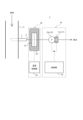
図1は、本開示の一実施形態に係る採水システム1の概略構成図である。図1を参照しながら、一実施形態に係る採水システム1の構成及び機能について主に説明する。図1において、構成部同士を結ぶ実線は流体の経路を示し、構成部同士を結ぶ破線は電気信号の経路を示す。
Figure 1 is a schematic diagram of a
採水システム1は、例えば水処理インフラにおける処理水などを試料水として採水するために用いられるシステムである。採水システム1により試料水として採水される流体は、例えば水処理インフラの一部を構成する配管2を一方向に流れる。例えば、このような流体の水質は、時間によって変化するとする。配管2は、水処理インフラにおいて主要な流路を構成してもよいし、主要な流路から分岐したバイパス流路を構成してもよい。
The
採水システム1は、配管2の側面に取り付けられる着脱式のバルブ3を有する。配管2を一方向に流れる流体の一部は、配管2におけるバルブ3の設置個所を採水点として採水される。採水システム1は流路4を有する。流路4は、着脱式のバルブ3から連続して配置される送液管によって構成される。流路4を構成する送液管は保冷構造を有してもよい。流路4には、採水点から流入した試料水が流れる。試料水は、流路4を流れて目的のウイルス又は粒子を試料として捕捉する後述のフィルタ21を通過した後、排水される。
The
採水システム1は、採水点から流入した試料水が流れる流路4に加えて、流路4を流れる試料水の流速を制御する制御装置10と、流路4において制御装置10よりも下流側に配置されるフィルタ装置20と、を有する。
The
フィルタ装置20は、流路4を流れる試料水をろ過して試料水に含まれるウイルス又は粒子を捕捉するフィルタ21と、フィルタ21を冷却する冷却部22と、冷却部22を制御してフィルタ21の温度を調整する温度制御部23と、を有する。
The
フィルタ21は、例えば、ウイルス又は粒子を吸着させて回収することが可能な陰電荷膜を含む。採水システム1は、バルブ3から流路4に流入して制御装置10を通過してきた試料水中のウイルス又は粒子の静電的中和を図り、凝集化したウイルス又は粒子をフィルタ21に含まれる陰電荷膜で捕捉することで試料の回収を実行する。
The
冷却部22は、フィルタ21を覆う金属部材と、金属部材を介して熱伝導によりフィルタ21を冷却する冷却機構と、を有する。例えば、金属部材は、熱伝導性の高い金属により形成される。冷却機構は、例えば、フィルタ21を覆う金属部材の温度を直接的に制御する、チラーに接続したコイルパイプ及びペルチェ素子クーラーなどを含む。冷却部22は、温度制御部23に接続される。すなわち、冷却部22に含まれる冷却機構は、温度制御部23により制御される。
The cooling
冷却部22は、例えばフィルタ21を着脱可能に構成されてもよい。すなわち、フィルタ21によるろ過が終了した後、冷却部22からフィルタ21を取り外して回収することが可能である。冷却部22は、例えばフィルタ21を遮光した状態で保持してもよい。
The cooling
温度制御部23は、1つ以上のプロセッサを含む。一実施形態において「プロセッサ」は、汎用のプロセッサ、又は特定の処理に特化した専用のプロセッサであるが、これらに限定されない。温度制御部23は、フィルタ装置20を構成する各構成部、例えば冷却部22と通信可能に接続され、フィルタ装置20全体の動作を制御する。
The
温度制御部23は、フィルタ21の温度を第1範囲に維持する。本明細書において、「第1範囲」は、例えばフィルタ21に捕捉されたウイルス又は粒子の性質の劣化を抑制可能な温度範囲を含む。すなわち、第1範囲は、フィルタ21に捕捉されたウイルス又は粒子の活性を抑制して、捕食、被食、増殖、死滅、及び分解を抑制可能な温度範囲を含む。例えば、第1範囲は、1℃以上10℃以下の温度範囲を含む。温度制御部23は、例えば最長で24時間のサンプリング期間中、フィルタ21の温度が第1範囲に維持されるように冷却部22を制御する。
The
図2は、図1の制御装置10の概略構成を示す機能ブロック図である。図1及び図2を参照しながら、制御装置10の構成及び機能について主に説明する。制御装置10は、測定部11、調整部12、入力部13、出力部14、記憶部15、及び制御部16を有する。
Figure 2 is a functional block diagram showing a schematic configuration of the
測定部11は、流路4を流れる試料水の流量及び流速の少なくとも一方を測定する。測定部11は、測定した情報を制御部16に送信する。本明細書において、「流量」は、例えば流路4を構成する送液管を単位時間あたりに通過する試料水の体積を意味し、L/sec又はm3/secの単位で表される。「流速」は、例えば流路4を構成する送液管の断面積で流量を除算したものを意味し、m/secの単位で表される。例えば、測定部11は、流路4において調整部12の下流側に配置され、かつ試料水の流量を測定する流量計11aを含む。これに限定されず、測定部11は、流路4上に配置され、かつ試料水の流速を測定する流速計を含んでもよい。
The measuring
調整部12は、制御部16から受信した制御信号に基づいて、流路4を流れる試料水の流速を調整する。流路4を構成する送液管が同一のものであり内径が一定であれば、調整部12は、流路4を流れる試料水の流速を調整することでその流量を調整することになる。例えば、調整部12は、流路4において流量計11aの上流側に配置され、かつ試料水の流速を調整する送液ポンプ12aを含む。
The
送液ポンプ12aは、流路4を流れる試料水を下流側に送液する。送液ポンプ12aは、例えば、軟質チューブをローラーでしごいて送液するペリスタポンプ(登録商標)であってもよいし、所定の試料水を送液可能な他の任意のポンプであってもよい。送液ポンプ12aの形式として、加圧及び吸引のいずれか一方が試料水の性質によって選択されてもよい。調整部12は、試料水に応じて加圧及び吸引形式の送液ポンプ12aのいずれか一方に組み換え可能に構成されてもよい。例えば、図1では、送液ポンプ12aは、ウイルス又は粒子を捕捉するフィルタ21の上流側に配置され、加圧形式を有する。
The
入力部13は、ユーザの入力操作を受け付けて、ユーザの操作に基づく入力情報を取得する1つ以上の入力インタフェースを含む。例えば、入力部13は、物理キー、静電容量キー、出力部14のディスプレイと一体的に設けられたタッチスクリーン、及び音声入力を受け付けるマイクなどを含むが、これらに限定されない。
The
出力部14は、ユーザに対して情報を出力する1つ以上の出力インタフェースを含む。例えば、出力部14は、情報を画像で出力するディスプレイ、及び情報を音声で出力するスピーカなどを含むが、これらに限定されない。
The
記憶部15は、HDD(Hard Disk Drive)、SSD(Solid State Drive)、EEPROM(Electrically Erasable Programmable Read-Only Memory)、ROM(Read-Only Memory)、及びRAM(Random Access Memory)を含む任意の記憶モジュールを含む。記憶部15は、例えば、主記憶装置、補助記憶装置、又はキャッシュメモリとして機能してもよい。記憶部15は、制御装置10の動作に用いられる任意の情報を記憶する。例えば、記憶部15は、システムプログラム及びアプリケーションプログラムなどを記憶する。記憶部15は、制御装置10に内蔵されるものに限定されず、USB(Universal Serial Bus)などのデジタル入出力ポートによって接続される外付け型の記憶モジュールを含んでもよい。
The
制御部16は、1つ以上のプロセッサを含む。一実施形態において「プロセッサ」は、汎用のプロセッサ、又は特定の処理に特化した専用のプロセッサであるが、これらに限定されない。制御部16は、制御装置10を構成する各構成部と通信可能に接続され、制御装置10全体の動作を制御する。
The
制御部16は、測定部11により測定された試料水の流量及び流速の少なくとも一方に基づいて調整部12を制御する。より具体的には、制御部16は、測定部11から送信された測定に関する情報を受信する。制御部16は、受信した測定に関する情報に基づいて調整部12に制御信号を送信する。制御部16は、流路4において試料水の流速が第2範囲に維持されるように調整部12を制御する。
The
より具体的には、制御部16は、流量計11aにより測定された試料水の流量に基づいて送液ポンプ12aを制御する。制御部16は、流量計11aから送信された流量の情報を受信する。制御部16は、受信した流量の情報に基づいて送液ポンプ12aに制御信号を送信する。制御部16は、流路4において試料水の流速が第2範囲に維持されるように送液ポンプ12aを制御する。すなわち、制御部16は、送液ポンプ12aと流量計11aとを互いに関連させながら、流路4を流れる試料水の採水速度及び瞬時的な採水量を調整する。
More specifically, the
例えば、制御部16は、あらかじめ取得した配管情報及び採水情報に基づいて第2範囲を算出してもよい。本明細書において、「配管情報」は、例えば流路4を構成する送液管の内径などを含む。「採水情報」は、採水期間、採水量の目標値、及び採水量に関する目標値からの許容範囲などを含む。
For example, the
本明細書において、「第2範囲」は、例えばあらかじめ設定された採水期間で設定された採水量の目標値に達するように流路4上で試料水を定常的に流すときの流速の範囲を含む。例えば、1日にわたり少量ずつ最大で1000Lの採水量を達成したいとき、1秒あたりに必要となる平均的な流量が算出可能である。加えて、流路4を構成する送液管の内径に基づいて平均的な流速が算出可能である。例えば、第2範囲は、このような平均的な流速に対して、あらかじめ設定された採水量に関する目標値からの許容範囲に基づき定められる誤差の範囲として算出されてもよい。例えば、制御部16は、試料水の流速が第2範囲に維持されながら、試料水が流路4を1日にわたり常時流れるように調整部12を制御してもよい。すなわち、制御部16は、試料水が流路4を1日にわたり常時流れるように試料水の流速を制御してもよい。
In this specification, the "second range" includes a range of flow rates when the sample water is steadily flowed through the
例えば、制御部16は、流路4における試料水の流速が第2範囲を下回りそうになった場合、配管2から試料水を引き込む力を強めるために、調整部12に含まれる送液ポンプ12aの動力を上げてもよい。例えば、制御部16は、流路4における試料水の流速が第2範囲を上回りそうになった場合、配管2から試料水を引き込む力を弱めるために、調整部12に含まれる送液ポンプ12aの動力を下げてもよい。
For example, when the flow rate of the sample water in the
図1のように配管2から流路4を経由して試料水がフィルタ装置20に流入する場合、試料水に含まれる濁質及び沈殿物などにより、流路4を構成する送液管が閉塞される可能性がある。このような送液管の閉塞を抑制するために、流路4を流れる試料水の流速が1m/sec以上となるように流路4を構成する送液管及び調整部12が設計されてもよい。例えば、流路4を構成する送液管の内径が15mmの場合、流速1m/secに対応する流量は、約170mL/sec(約10L/min)である。したがって、一実施形態では、第2範囲は、1m/sec以上の範囲に含まれてもよい。
When sample water flows into the
図3は、本開示の制御装置10による制御方法を説明するためのフローチャートである。図3を参照しながら、図1の制御装置10を用いて実行される制御方法について主に説明する。
Figure 3 is a flowchart for explaining a control method by the
ステップS100では、制御装置10の制御部16は配管情報を取得する。例えば、このような配管情報は、ユーザにより入力部13を用いて入力され、入力部13から制御部16へと送信されてもよい。
In step S100, the
ステップS101では、制御部16は採水情報を取得する。例えば、このような採水情報は、ユーザにより入力部13を用いて入力され、入力部13から制御部16へと送信されてもよい。
In step S101, the
ステップS102では、制御部16は、ステップS100において取得した配管情報及びステップS101において取得した採水情報に基づいて第2範囲を算出する。
In step S102, the
ステップS103では、制御部16は、測定部11を用いて流路4を流れる試料水の流量及び流速の少なくとも一方を測定する。
In step S103, the
ステップS104では、制御部16は、ステップS103において測定された試料水の流量及び流速の少なくとも一方に基づいて流路4を流れる試料水の流速を制御する。制御部16は、ステップS104において、試料水の流速がステップS102において算出した第2範囲に維持されるように調整部12を制御する。
In step S104, the
一実施形態に係る採水システム1では、デッドエンドろ過方式及び、より強いろ過駆動力を生じさせる加圧方式を導入し、例えば日ごとに1000Lの被処理水からウイルス又は粒子をフィルタ21により捕捉する。このとき、毎時42L程度以上のろ過が、膜面積5m2以下で実施される。これにより、ろ過膜としてのフィルタ21を保管するフィルタ装置20がよりコンパクトに設計可能となる。
In the
以上のような一実施形態によれば、試料水に含まれるウイルス又は粒子を捕捉するフィルタ21上の試料の性質変化を抑制することが可能である。例えば、フィルタ装置20及び採水システム1は、フィルタ21を冷却する冷却部22と、冷却部22を制御してフィルタ21の温度を調整する温度制御部23と、を有することで、ウイルス又は粒子を捕捉したフィルタ21を適切な温度に冷却可能である。例えば、流路4を構成する送液管のような細い管路を流れる試料水は流量が小さく、試料水がフィルタ21に対して与える熱的な影響は比較的小さい。フィルタ装置20及び採水システム1は、冷却部22及び温度制御部23を用いてフィルタ21を効率良く冷却可能である。フィルタ21を適切な温度まで冷却することで、フィルタ21に捕捉されたウイルス又は粒子の活性を抑制して、捕食、被食、増殖、死滅、及び分解が抑制可能である。
According to the embodiment described above, it is possible to suppress changes in the properties of the sample on the
例えば、フィルタ21がウイルス又は粒子を選択的に捕捉するため、フィルタ21ではなく試料水自体を冷却する場合と比較して、フィルタ21に捕捉されている試料が限定される。したがって、試料水中で多種類のウイルス又は粒子が自由に存在している場合よりも、フィルタ21上でウイルス又は粒子間の相互作用が抑制される。これにより、ウイルス又は粒子の活性が抑制される。試料を捕捉し終わってからフィルタ21を取り出すまでの間においてもウイルス又は粒子の活性が抑制される。
For example, because the
冷却部22は、フィルタ21を覆う金属部材と、金属部材を介して熱伝導によりフィルタ21を冷却する冷却機構と、を有することで、温度制御部23による冷却機構の制御によってフィルタ21を熱伝導により間接的に冷却することができる。温度制御部23によって冷却機構を精度良く制御することが可能であるので、フィルタ装置20及び採水システム1は、フィルタ21を精度良く冷却することができる。
The cooling
温度制御部23がフィルタ21の温度を第1範囲に維持することで、フィルタ装置20及び採水システム1は、フィルタ21に捕捉されたウイルス又は粒子の劣化を最小限に抑制可能である。すなわち、フィルタ装置20及び採水システム1は、フィルタ21に捕捉されたウイルス又は粒子の活性を最小限に抑制して、捕食、被食、増殖、死滅、及び分解を最小限に抑制可能である。フィルタ装置20及び採水システム1は、冷却部22による保冷効果により適切な温度でフィルタ21を保管することが可能である。
By the
冷却部22がフィルタ21を着脱可能に構成されることで、採水者は、一のフィルタ21においてウイルス又は粒子の捕捉が完了した時点で、当該一のフィルタ21を他のフィルタ21に容易に交換可能である。
The cooling
冷却部22がフィルタ21を遮光した状態で保持することで、フィルタ装置20及び採水システム1は、ウイルス又は粒子を捕捉したフィルタ21に対する保冷効果を向上させることができる。加えて、フィルタ装置20及び採水システム1は、外部から入射する光によって生じるウイルス又は粒子の性質の劣化を抑制可能である。以上により、フィルタ装置20及び採水システム1は、温度を要因とするウイルス又は粒子の変質だけでなく光を要因とするウイルス又は粒子の変質も抑制可能である。
By the
採水システム1は、試料水の水質変動の適切な把握に寄与することができる。例えば、採水システム1に含まれる制御装置10は、流路4を流れる試料水の流速が第2範囲に維持されるように調整部12を制御して流速を制御する。このような制御装置10による制御によって、採水システム1は、試料水の流速及び流量を定常的に維持しながら長期にわたって採水処理を実行することができる。採水システム1は、試料水を少量ずつ定常的に採水しながら長期にわたってフィルタ21に透過させることも可能となる。
The
したがって、採水システム1は、最悪又は最大の微生物学的負荷を含む試料水に対してフィルタ21により試料を漏れなく適切に回収することができる。採水システム1による上記のような試料回収方法によって、試料水の水質に関する突発的な変動を検出したり、ワーストケースを検出したりすることも可能となる。採水時に発生した水質の最悪条件が試料に反映され、最悪の事態によってもたらされる質的リスクを逃さないことが可能となる。採水システム1は、目的とする流体全体の汚染状況を反映した、代表的サンプル及び平均的サンプルとして試料を回収することができる。結果として、試料水の水質変動及び水処理システムの制御性能を適切に把握することが容易となる。
Therefore, the
測定部11が流量計11aを含むことで、制御装置10は、流速が第2範囲に維持されるように調整部12を制御するときに、流量計11aにより測定された流量を参照しながら制御処理を実行することができる。加えて、調整部12が試料水の流速を調整する送液ポンプ12aを含むことも可能である。採水システム1は、流路4上でより大きな流速及び流量を達成することが可能である。したがって、試料水に含まれる濁質及び沈殿物などによる、流路4を構成する送液管の閉塞が抑制される。例えば、第2範囲が1m/sec以上の範囲に含まれることで、このような効果が顕著になる。採水システム1では、送液ポンプ12aを使用することにより、試料水を下流側に送るために十分な圧力を確保することも可能である。
By including the
制御装置10が、試料水が流路4を1日にわたり常時流れるように試料水の流速を制御することで、採水システム1は、バルブ3を介して得られた試料水を、例えば1日という所定期間ごとにフィルタ21に透過させることも可能となる。例えば、採水システム1は、試料水の所定期間ごとの採水を365日継続して、時間ごと、日ごと、及び月ごとなどの変動を長期的に評価するために用いることも可能である。採水システム1は、例えば24時間の長時間にわたる試料水の連続的な採水においても、冷却部22によるフィルタ21の冷却及び保冷効果によって、以後の解析が実施可能となるまで、フィルタ21に捕捉されたウイルス又は粒子の性質の劣化を抑制可能である。採水システム1は、例えば24時間の長時間にわたる試料水の連続的な採水においても、ウイルス又は粒子を捕捉したフィルタ21に対する適切な保管条件を冷却部22により維持可能である。
The
バルブ3は、着脱式であることで、採水システム1による採水処理が実行されていないときに取り外して洗浄可能である。
The
流路4を構成する送液管が保冷構造を有することで、流路4を流れる試料水の温度を維持した状態で試料水をフィルタ21に透過させることが可能となる。
The liquid delivery tube that constitutes
本開示を諸図面及び実施例に基づき説明してきたが、当業者であれば本開示に基づき種々の変形及び改変を行うことが可能であることに注意されたい。したがって、これらの変形及び改変は本開示の範囲に含まれることに留意されたい。例えば、各構成又は各ステップに含まれる機能などは論理的に矛盾しないように再配置可能であり、複数の構成又はステップを1つに組み合わせたり、或いは分割したりすることが可能である。 Although the present disclosure has been described based on the drawings and examples, it should be noted that a person skilled in the art would be able to make various modifications and alterations based on the present disclosure. Therefore, it should be noted that these modifications and alterations are included in the scope of the present disclosure. For example, the functions included in each configuration or step can be rearranged so as not to cause logical inconsistencies, and multiple configurations or steps can be combined into one or divided.
例えば、本開示は、上述した制御装置10の各機能を実現する処理内容を記述したプログラム又はプログラムを記録した記憶媒体としても実現し得る。本開示の範囲には、これらも包含されると理解されたい。
For example, the present disclosure may also be realized as a program describing the processing contents for implementing each function of the
例えば、上述した各構成部の形状、配置、向き、及び個数は、上記の説明及び図面における図示の内容に限定されない。各構成部の形状、配置、向き、及び個数は、その機能を実現できるのであれば、任意に構成されてもよい。 For example, the shape, arrangement, orientation, and number of each of the above-mentioned components are not limited to the above description and the illustrations in the drawings. The shape, arrangement, orientation, and number of each of the components may be configured arbitrarily as long as the function can be realized.
図4は、図1の採水システム1の第1変形例を示す概略構成図である。上記実施形態では、フィルタ装置20は制御装置10の下流側に配置され、送液ポンプ12aは加圧形式を有すると説明したが、これに限定されない。図4に示すとおり、フィルタ装置20は、制御装置10の上流側に配置されてもよい。このとき、送液ポンプ12aは吸引形式を有してもよい。
Figure 4 is a schematic diagram showing a first modified example of the
図5は、図1の採水システム1の第2変形例を示す概略構成図である。図5において、構成部同士を結ぶ実線は流体の経路を示し、構成部同士を結ぶ破線は電気信号の経路を示す。
Figure 5 is a schematic diagram showing a second modified example of the
第2変形例に係る採水システム1は、制御装置10の調整部12が送液ポンプ12aに代えて絞り弁12bを含む点で相違する。第2変形例に係る採水システム1では、試料水は、配管2においてバルブ3が取り付けられている採水地点での残存圧力を利用して、流路4の下流側へと送液される。このとき、採水速度が小さく、流路4に沈殿が生じる場合を想定している。より具体的には、流路4を流れる試料水の流速が1m/secよりも小さくなる場合を想定している。その他の構成、機能、及び効果などについては、図1の採水システム1と同様であり、対応する説明が第2変形例に係る制御装置10及び採水システム1においても当てはまる。以下では、図1と同様の構成部については同一の符号を付し、その説明を省略する。図1と異なる点について主に説明する。
The
第2変形例に係る制御装置10の調整部12は、送液ポンプ12aに代えて、流路4上に配置され、かつ試料水の流速を調整する絞り弁12bを含む。例えば、絞り弁12bは、流路4を流れる試料水の流量を測定する流量計11aと一体的に構成される。すなわち、測定部11と調整部12とは、一の部品として一体的に構成されてもよい。
The
絞り弁12bは、絞り開度を変えることによって、下流側に流れる試料水の流量及び流速を無段階に調整可能な弁である。絞り弁12bと一体化した流量計11aは、流量測定機能を有し、絞り弁12bを通過する試料水の流量を測定可能である。
Throttling
制御部16は、流量計11aにより測定された試料水の流量に基づいて絞り弁12bを制御する。より具体的には、制御部16は、流量計11aから送信された流量の情報を受信する。制御部16は、受信した流量の情報に基づいて絞り弁12bに制御信号を送信する。制御部16は、流路4において試料水の流速が第2範囲に維持されるように絞り弁12bを制御する。より具体的には、制御部16は、絞り弁12bにおける絞り開度を調整することにより、試料水の下流側への流速及び流量を調整する。制御部16は、絞り弁12bと流量計11aとを互いに関連させながら、流路4を流れる試料水の採水速度及び瞬時的な採水量を調整する。
The
例えば、制御部16は、流路4における試料水の流速が第2範囲を下回りそうになった場合、調整部12に含まれる絞り弁12bの絞り開度を上げてもよい。例えば、制御部16は、流路4における試料水の流速が第2範囲を上回りそうになった場合、調整部12に含まれる絞り弁12bの絞り開度を下げてもよい。
For example, the
調整部12は、絞り弁12bに加えて、絞り弁12bを通過しない余剰の試料水を排水する排水流路12cを含んでもよい。排水流路12cは、絞り弁12bよりも上流側において、流路4から分岐するように流路4と連通して配置される。排水流路12cは、可能な限り絞り弁12bに近い位置で、流路4から分岐するように配置されることが好ましい。排水流路12cが流路4から分岐する位置が絞り弁12bに近いほど、流路4を流れる試料水を絞り弁12bに近い位置で排水することができる。このように排水流路12cが流路4から分岐する位置と絞り弁12bとが互いに近接して試料水の流量が少なくなる配管距離が短くなることで、沈殿が生じ得る配管距離を可能な限り短くすることができる。
In addition to the
排水流路12cは、採水システム1による試料水の採水処理が実行されている間、絞り弁12bを通過しない余剰の試料水を排水する排水路として機能する。排水流路12cは、採水処理の後に、後述する洗浄部18から流路4に洗浄水が供給されている間、洗浄水を排水する排水路として機能する。
The
制御装置10は、図2に示す構成部に加えて洗浄部18を有してもよい。洗浄部18は、絞り弁12b及び排水流路12cよりも上流側の流路4を洗浄水によって洗浄する。洗浄部18は、試料水に含まれる濁質及び沈殿物などによる、流路4を構成する配管の閉塞を抑制する。洗浄部18は、洗浄水の供給源18aと、当該供給源18aから延びる流路18bと、流路18b上に配置される電磁弁18cと、を含む。
The
流路18bは、バルブ3よりも下流側で流路4と合流して洗浄水を流入させるために供給源18aと流路4との間に配置されている。洗浄水は、採水システム1による試料水の採水処理が実行された後、流路4を洗浄するために供給される流体である。流路18bは、可能な限りバルブ3に近い位置で流路4と合流するように配置されることが好ましい。流路18bが流路4と合流する位置がバルブ3に近いほど、洗浄水を流路4のより上流側から供給し、流路4を洗浄することが可能となる。一方で、排水流路12cが、可能な限り絞り弁12bに近い位置で配置されることで、洗浄水を流路4のより下流側まで供給し、流路4を洗浄することが可能となる。
The
フィルタ装置20におけるフィルタ21は、絞り弁12bの下流側で、可能な限り絞り弁12bに近い位置に配置されることが好ましい。フィルタ21が絞り弁12bに近いほど、流路4を流れる試料水中のウイルス又は粒子を絞り弁12bに近い位置で捕捉可能である。このようにフィルタ21が絞り弁12bに近接して試料水の流量が少なくなる配管距離が短くなることで、沈殿が生じ得る配管距離を可能な限り短くすることができる。
The
図5の採水システム1では、排水経路は、絞り弁12bの上流側の排水流路12c及びフィルタ21透過後の流路の2経路として存在する。絞り弁12bの上流側における排水流路12cの排水量は、フィルタ21透過後の流路の排水量と比較して多くなる。
In the
以上のような第2変形例によれば、図1の採水システム1と同様に試料水の水質変動の適切な把握に寄与することができる。制御装置10は、調整部12が絞り弁12bと排水流路12cとを含むことで、送液ポンプ12aなどのポンプを用いることなく、試料水の流速を第2範囲に維持することが可能である。
The second modified example described above can contribute to an appropriate understanding of the fluctuations in the quality of the sample water, similar to the
制御装置10は、洗浄部18を有することで、採水システム1による採水処理により試料水に含まれる濁質及び沈殿物などが流路4を構成する配管に蓄積したとしても、これらを洗い流すことができる。したがって、試料水に含まれる濁質及び沈殿物などによる、流路4を構成する配管の閉塞が抑制される。
By having the cleaning
上記実施形態では、冷却部22は、フィルタ21を覆う金属部材と、金属部材を介して熱伝導によりフィルタ21を冷却する冷却機構と、を有すると説明したが、これに限定されない。冷却部22は、金属部材を有さずに、冷却機構によってフィルタ21を直接的に冷却してもよい。
In the above embodiment, the cooling
上記実施形態では、フィルタ装置20は、フィルタ21の温度を第1範囲に維持すると説明したが、これに限定されない。フィルタ21の温度は第1範囲に含まれていなくてもよい。例えば、フィルタ装置20は、フィルタ21の温度が第1範囲よりも若干高くなるようにフィルタ21を冷却してもよい。
In the above embodiment, the
上記実施形態では、フィルタ装置20は、フィルタ21を遮光した状態で保持すると説明したが、これに限定されない。フィルタ装置20は、ウイルス又は粒子を捕捉したフィルタ21を冷却可能な任意の態様で構成されてもよい。例えば、フィルタ装置20は、遮光機能を有していなくてもよい。
In the above embodiment, the
採水システム1では、水道、食品、及び飲料水などを含む上記の様々な分野への応用を可能とするために、試料水の採水期間は可変であってもよい。採水のためのバルブ3の形状は可変であってよい。
In the
上記実施形態では、流路4を構成する送液管は保冷構造を有すると説明したが、これに限定されない。送液管は、保冷構造を有さなくてもよい。
In the above embodiment, the liquid supply pipe constituting the
1 採水システム
2 配管
3 バルブ
4 流路
10 制御装置
11 測定部
11a 流量計
12 調整部
12a 送液ポンプ
12b 絞り弁
12c 排水流路
13 入力部
14 出力部
15 記憶部
16 制御部
18 洗浄部
18a 供給源
18b 流路
18c 電磁弁
20 フィルタ装置
21 フィルタ
22 冷却部
23 温度制御部
REFERENCE SIGNS
Claims (9)
前記フィルタを覆う金属部材を介して熱伝導により前記フィルタを冷却する冷却部と、
前記冷却部を制御して前記フィルタの温度を調整する温度制御部と、
を備える、
フィルタ装置。 a filter that filters the sample water flowing through the flow path to capture viruses or particles contained in the sample water;
a cooling unit that cools the filter by thermal conduction through a metal member that covers the filter;
a temperature control unit that controls the cooling unit to adjust the temperature of the filter;
Equipped with
Filter device.
請求項1に記載のフィルタ装置。 The temperature control unit maintains the temperature of the filter within a first range.
The filter device according to claim 1 .
請求項1又は2に記載のフィルタ装置。 The cooling unit is configured so that the filter can be detached.
3. A filter device according to claim 1 or 2 .
請求項1乃至3のいずれか1項に記載のフィルタ装置。 The cooling unit holds the filter in a light-shielded state.
A filter device according to any one of claims 1 to 3 .
前記流路上に配置される、請求項1乃至4のいずれか1項に記載のフィルタ装置と、
前記流路を流れる前記試料水の流速が第2範囲に維持されるように前記流速を制御する制御装置と、
を備える、
採水システム。 the flow path through which the sample water flows from a water sampling point;
A filter device according to claim 1 , which is disposed on the flow path; and
a control device that controls a flow rate of the sample water flowing through the flow path so that the flow rate is maintained within a second range;
Equipped with
Water collection system.
請求項5に記載の採水システム。 The control device includes a flow meter for measuring a flow rate of the sample water flowing through the flow path, and a liquid delivery pump for adjusting a flow rate of the sample water.
The water sampling system according to claim 5 .
請求項5に記載の採水システム。 The control device has a flow meter for measuring a flow rate of the sample water flowing through the flow path, a throttle valve for adjusting a flow rate of the sample water, and a drainage flow path for draining excess sample water that does not pass through the throttle valve.
The water sampling system according to claim 5 .
請求項5乃至7のいずれか1項に記載の採水システム。 The control device controls the flow rate so that the sample water constantly flows through the flow path over a day.
8. A water sampling system according to any one of claims 5 to 7 .
請求項5乃至8のいずれか1項に記載の採水システム。 The liquid sending pipe constituting the flow path has a cold insulation structure.
9. A water sampling system according to any one of claims 5 to 8 .
Priority Applications (1)
| Application Number | Priority Date | Filing Date | Title |
|---|---|---|---|
| JP2021054186A JP7589618B2 (en) | 2021-03-26 | 2021-03-26 | Filter device and water sampling system |
Applications Claiming Priority (1)
| Application Number | Priority Date | Filing Date | Title |
|---|---|---|---|
| JP2021054186A JP7589618B2 (en) | 2021-03-26 | 2021-03-26 | Filter device and water sampling system |
Publications (2)
| Publication Number | Publication Date |
|---|---|
| JP2022151218A JP2022151218A (en) | 2022-10-07 |
| JP7589618B2 true JP7589618B2 (en) | 2024-11-26 |
Family
ID=83465130
Family Applications (1)
| Application Number | Title | Priority Date | Filing Date |
|---|---|---|---|
| JP2021054186A Active JP7589618B2 (en) | 2021-03-26 | 2021-03-26 | Filter device and water sampling system |
Country Status (1)
| Country | Link |
|---|---|
| JP (1) | JP7589618B2 (en) |
Citations (5)
| Publication number | Priority date | Publication date | Assignee | Title |
|---|---|---|---|---|
| JP2002543971A (en) | 1999-05-14 | 2002-12-24 | ポール・コーポレーション | Charged membrane |
| JP2004329033A (en) | 2003-04-30 | 2004-11-25 | Japan Science & Technology Agency | Sample filtration device |
| JP2005177743A (en) | 2003-11-24 | 2005-07-07 | Millipore Corp | Purification and concentration of synthetic biological molecule |
| JP2012173133A (en) | 2011-02-22 | 2012-09-10 | Nissin Electric Co Ltd | Soluble component water sampling device |
| JP2022101225A (en) | 2020-12-24 | 2022-07-06 | 大成建設株式会社 | Environmental dna sampling device and environmental dna sampling method |
Family Cites Families (2)
| Publication number | Priority date | Publication date | Assignee | Title |
|---|---|---|---|---|
| JPS6372314A (en) * | 1986-09-16 | 1988-04-02 | Hitachi Ltd | Filter |
| JPS6484131A (en) * | 1987-09-28 | 1989-03-29 | Nagayama Kankyo Kagaku Kenkyus | Water sampler |
-
2021
- 2021-03-26 JP JP2021054186A patent/JP7589618B2/en active Active
Patent Citations (5)
| Publication number | Priority date | Publication date | Assignee | Title |
|---|---|---|---|---|
| JP2002543971A (en) | 1999-05-14 | 2002-12-24 | ポール・コーポレーション | Charged membrane |
| JP2004329033A (en) | 2003-04-30 | 2004-11-25 | Japan Science & Technology Agency | Sample filtration device |
| JP2005177743A (en) | 2003-11-24 | 2005-07-07 | Millipore Corp | Purification and concentration of synthetic biological molecule |
| JP2012173133A (en) | 2011-02-22 | 2012-09-10 | Nissin Electric Co Ltd | Soluble component water sampling device |
| JP2022101225A (en) | 2020-12-24 | 2022-07-06 | 大成建設株式会社 | Environmental dna sampling device and environmental dna sampling method |
Also Published As
| Publication number | Publication date |
|---|---|
| JP2022151218A (en) | 2022-10-07 |
Similar Documents
| Publication | Publication Date | Title |
|---|---|---|
| JP4445569B2 (en) | Filtrated water monitoring device and filtered water monitoring system | |
| CN101384342B (en) | Method and system for monitoring reverse osmosis membranes | |
| US9409110B2 (en) | Method of maintaining water quality in a process stream | |
| RU2536993C2 (en) | Device for production of superpure water | |
| JP2018171577A (en) | Pure water production method and apparatus | |
| CN101267874A (en) | Filtered water monitoring device and filtered water monitoring system | |
| JPWO2017221984A1 (en) | Trouble determination program, trouble determination device, and recording medium for fresh water generation system | |
| JP7589618B2 (en) | Filter device and water sampling system | |
| JP5878038B2 (en) | Water quality measurement system | |
| Panglisch et al. | Monitoring the integrity of capillary membranes by particle counters | |
| JP7582014B2 (en) | Water Sampling System | |
| JP3473309B2 (en) | Operation control device for membrane separation device | |
| JP2023017828A (en) | Water sampling method, water sampling device, and water sampling system | |
| JP2013184157A (en) | Membrane separation apparatus, membrane fouling measurement method, membrane separation apparatus operation method, and submodule | |
| JP2013015512A (en) | Water quality measuring apparatus and filtration unit | |
| JP7192906B2 (en) | Control device and control method | |
| JP2005262048A (en) | Water supply management system | |
| Hong et al. | Assessing pathogen removal efficiency of microfiltration by monitoring membrane integrity | |
| JP7719614B2 (en) | FI measurement unit for raw water for dialysis, and FI information system for raw water for dialysis | |
| JP4931039B2 (en) | Water quality monitoring equipment and water treatment equipment | |
| NL2021215B1 (en) | A system for monitoring fouling issues in a drinking water distribution network | |
| CN205662399U (en) | Filtration equipment with sampling device | |
| JP2020160011A (en) | Sample measuring device | |
| CN209161706U (en) | A kind of purifying water treatment system of automatic detection water quality | |
| CN203763969U (en) | Membrane technology filtering device |
Legal Events
| Date | Code | Title | Description |
|---|---|---|---|
| A621 | Written request for application examination |
Free format text: JAPANESE INTERMEDIATE CODE: A621 Effective date: 20231110 |
|
| A977 | Report on retrieval |
Free format text: JAPANESE INTERMEDIATE CODE: A971007 Effective date: 20240626 |
|
| A131 | Notification of reasons for refusal |
Free format text: JAPANESE INTERMEDIATE CODE: A131 Effective date: 20240702 |
|
| A521 | Request for written amendment filed |
Free format text: JAPANESE INTERMEDIATE CODE: A523 Effective date: 20240731 |
|
| A131 | Notification of reasons for refusal |
Free format text: JAPANESE INTERMEDIATE CODE: A131 Effective date: 20240903 |
|
| A521 | Request for written amendment filed |
Free format text: JAPANESE INTERMEDIATE CODE: A523 Effective date: 20241003 |
|
| TRDD | Decision of grant or rejection written | ||
| A01 | Written decision to grant a patent or to grant a registration (utility model) |
Free format text: JAPANESE INTERMEDIATE CODE: A01 Effective date: 20241015 |
|
| A61 | First payment of annual fees (during grant procedure) |
Free format text: JAPANESE INTERMEDIATE CODE: A61 Effective date: 20241028 |
|
| R150 | Certificate of patent or registration of utility model |
Ref document number: 7589618 Country of ref document: JP Free format text: JAPANESE INTERMEDIATE CODE: R150 |