JP7581317B2 - 最終製品特性の自動調整を備えた塗料製造システムとその方法 - Google Patents
最終製品特性の自動調整を備えた塗料製造システムとその方法 Download PDFInfo
- Publication number
- JP7581317B2 JP7581317B2 JP2022502314A JP2022502314A JP7581317B2 JP 7581317 B2 JP7581317 B2 JP 7581317B2 JP 2022502314 A JP2022502314 A JP 2022502314A JP 2022502314 A JP2022502314 A JP 2022502314A JP 7581317 B2 JP7581317 B2 JP 7581317B2
- Authority
- JP
- Japan
- Prior art keywords
- tank
- ccu
- control unit
- central control
- station
- Prior art date
- Legal status (The legal status is an assumption and is not a legal conclusion. Google has not performed a legal analysis and makes no representation as to the accuracy of the status listed.)
- Active
Links
Images

Classifications
-
- G—PHYSICS
- G05—CONTROLLING; REGULATING
- G05D—SYSTEMS FOR CONTROLLING OR REGULATING NON-ELECTRIC VARIABLES
- G05D11/00—Control of flow ratio
- G05D11/02—Controlling ratio of two or more flows of fluid or fluent material
- G05D11/13—Controlling ratio of two or more flows of fluid or fluent material characterised by the use of electric means
- G05D11/135—Controlling ratio of two or more flows of fluid or fluent material characterised by the use of electric means by sensing at least one property of the mixture
- G05D11/136—Controlling ratio of two or more flows of fluid or fluent material characterised by the use of electric means by sensing at least one property of the mixture by sensing the viscosity
-
- B—PERFORMING OPERATIONS; TRANSPORTING
- B01—PHYSICAL OR CHEMICAL PROCESSES OR APPARATUS IN GENERAL
- B01F—MIXING, e.g. DISSOLVING, EMULSIFYING OR DISPERSING
- B01F33/00—Other mixers; Mixing plants; Combinations of mixers
- B01F33/80—Mixing plants; Combinations of mixers
-
- B—PERFORMING OPERATIONS; TRANSPORTING
- B01—PHYSICAL OR CHEMICAL PROCESSES OR APPARATUS IN GENERAL
- B01F—MIXING, e.g. DISSOLVING, EMULSIFYING OR DISPERSING
- B01F25/00—Flow mixers; Mixers for falling materials, e.g. solid particles
- B01F25/50—Circulation mixers, e.g. wherein at least part of the mixture is discharged from and reintroduced into a receptacle
- B01F25/53—Circulation mixers, e.g. wherein at least part of the mixture is discharged from and reintroduced into a receptacle in which the mixture is discharged from and reintroduced into a receptacle through a recirculation tube, into which an additional component is introduced
-
- B—PERFORMING OPERATIONS; TRANSPORTING
- B01—PHYSICAL OR CHEMICAL PROCESSES OR APPARATUS IN GENERAL
- B01F—MIXING, e.g. DISSOLVING, EMULSIFYING OR DISPERSING
- B01F27/00—Mixers with rotary stirring devices in fixed receptacles; Kneaders
- B01F27/05—Stirrers
- B01F27/11—Stirrers characterised by the configuration of the stirrers
- B01F27/115—Stirrers characterised by the configuration of the stirrers comprising discs or disc-like elements essentially perpendicular to the stirrer shaft axis
- B01F27/1152—Stirrers characterised by the configuration of the stirrers comprising discs or disc-like elements essentially perpendicular to the stirrer shaft axis with separate elements other than discs fixed on the discs, e.g. vanes fixed on the discs
-
- B—PERFORMING OPERATIONS; TRANSPORTING
- B01—PHYSICAL OR CHEMICAL PROCESSES OR APPARATUS IN GENERAL
- B01F—MIXING, e.g. DISSOLVING, EMULSIFYING OR DISPERSING
- B01F27/00—Mixers with rotary stirring devices in fixed receptacles; Kneaders
- B01F27/80—Mixers with rotary stirring devices in fixed receptacles; Kneaders with stirrers rotating about a substantially vertical axis
- B01F27/88—Mixers with rotary stirring devices in fixed receptacles; Kneaders with stirrers rotating about a substantially vertical axis with a separate receptacle-stirrer unit that is adapted to be coupled to a drive mechanism
-
- B—PERFORMING OPERATIONS; TRANSPORTING
- B01—PHYSICAL OR CHEMICAL PROCESSES OR APPARATUS IN GENERAL
- B01F—MIXING, e.g. DISSOLVING, EMULSIFYING OR DISPERSING
- B01F33/00—Other mixers; Mixing plants; Combinations of mixers
- B01F33/80—Mixing plants; Combinations of mixers
- B01F33/834—Mixing in several steps, e.g. successive steps
-
- B—PERFORMING OPERATIONS; TRANSPORTING
- B01—PHYSICAL OR CHEMICAL PROCESSES OR APPARATUS IN GENERAL
- B01F—MIXING, e.g. DISSOLVING, EMULSIFYING OR DISPERSING
- B01F33/00—Other mixers; Mixing plants; Combinations of mixers
- B01F33/80—Mixing plants; Combinations of mixers
- B01F33/84—Mixing plants with mixing receptacles receiving material dispensed from several component receptacles, e.g. paint tins
- B01F33/841—Mixing plants with mixing receptacles receiving material dispensed from several component receptacles, e.g. paint tins with component receptacles fixed in a circular configuration on a horizontal table, e.g. the table being able to be indexed about a vertical axis
-
- B—PERFORMING OPERATIONS; TRANSPORTING
- B01—PHYSICAL OR CHEMICAL PROCESSES OR APPARATUS IN GENERAL
- B01F—MIXING, e.g. DISSOLVING, EMULSIFYING OR DISPERSING
- B01F33/00—Other mixers; Mixing plants; Combinations of mixers
- B01F33/80—Mixing plants; Combinations of mixers
- B01F33/84—Mixing plants with mixing receptacles receiving material dispensed from several component receptacles, e.g. paint tins
- B01F33/846—Mixing plants with mixing receptacles receiving material dispensed from several component receptacles, e.g. paint tins using stored recipes for determining the composition of the mixture to be produced, i.e. for determining the amounts of the basic components to be dispensed from the component receptacles
-
- B—PERFORMING OPERATIONS; TRANSPORTING
- B01—PHYSICAL OR CHEMICAL PROCESSES OR APPARATUS IN GENERAL
- B01F—MIXING, e.g. DISSOLVING, EMULSIFYING OR DISPERSING
- B01F33/00—Other mixers; Mixing plants; Combinations of mixers
- B01F33/80—Mixing plants; Combinations of mixers
- B01F33/85—Mixing plants with mixing receptacles or mixing tools that can be indexed into different working positions
-
- B—PERFORMING OPERATIONS; TRANSPORTING
- B01—PHYSICAL OR CHEMICAL PROCESSES OR APPARATUS IN GENERAL
- B01F—MIXING, e.g. DISSOLVING, EMULSIFYING OR DISPERSING
- B01F35/00—Accessories for mixers; Auxiliary operations or auxiliary devices; Parts or details of general application
- B01F35/10—Maintenance of mixers
- B01F35/145—Washing or cleaning mixers not provided for in other groups in this subclass; Inhibiting build-up of material on machine parts using other means
- B01F35/1452—Washing or cleaning mixers not provided for in other groups in this subclass; Inhibiting build-up of material on machine parts using other means using fluids
-
- B—PERFORMING OPERATIONS; TRANSPORTING
- B01—PHYSICAL OR CHEMICAL PROCESSES OR APPARATUS IN GENERAL
- B01F—MIXING, e.g. DISSOLVING, EMULSIFYING OR DISPERSING
- B01F35/00—Accessories for mixers; Auxiliary operations or auxiliary devices; Parts or details of general application
- B01F35/181—Preventing generation of dust or dirt; Sieves; Filters
- B01F35/186—Preventing generation of dust or dirt; Sieves; Filters using splash guards in mixers for avoiding dirt or projection of material
-
- B—PERFORMING OPERATIONS; TRANSPORTING
- B01—PHYSICAL OR CHEMICAL PROCESSES OR APPARATUS IN GENERAL
- B01F—MIXING, e.g. DISSOLVING, EMULSIFYING OR DISPERSING
- B01F35/00—Accessories for mixers; Auxiliary operations or auxiliary devices; Parts or details of general application
- B01F35/20—Measuring; Control or regulation
- B01F35/21—Measuring
- B01F35/211—Measuring of the operational parameters
- B01F35/2117—Weight
-
- B—PERFORMING OPERATIONS; TRANSPORTING
- B01—PHYSICAL OR CHEMICAL PROCESSES OR APPARATUS IN GENERAL
- B01F—MIXING, e.g. DISSOLVING, EMULSIFYING OR DISPERSING
- B01F35/00—Accessories for mixers; Auxiliary operations or auxiliary devices; Parts or details of general application
- B01F35/20—Measuring; Control or regulation
- B01F35/21—Measuring
- B01F35/213—Measuring of the properties of the mixtures, e.g. temperature, density or colour
-
- B—PERFORMING OPERATIONS; TRANSPORTING
- B01—PHYSICAL OR CHEMICAL PROCESSES OR APPARATUS IN GENERAL
- B01F—MIXING, e.g. DISSOLVING, EMULSIFYING OR DISPERSING
- B01F35/00—Accessories for mixers; Auxiliary operations or auxiliary devices; Parts or details of general application
- B01F35/71—Feed mechanisms
- B01F35/717—Feed mechanisms characterised by the means for feeding the components to the mixer
- B01F35/7176—Feed mechanisms characterised by the means for feeding the components to the mixer using pumps
-
- B—PERFORMING OPERATIONS; TRANSPORTING
- B01—PHYSICAL OR CHEMICAL PROCESSES OR APPARATUS IN GENERAL
- B01F—MIXING, e.g. DISSOLVING, EMULSIFYING OR DISPERSING
- B01F35/00—Accessories for mixers; Auxiliary operations or auxiliary devices; Parts or details of general application
- B01F35/75—Discharge mechanisms
- B01F35/754—Discharge mechanisms characterised by the means for discharging the components from the mixer
- B01F35/7547—Discharge mechanisms characterised by the means for discharging the components from the mixer using valves, gates, orifices or openings
-
- F—MECHANICAL ENGINEERING; LIGHTING; HEATING; WEAPONS; BLASTING
- F28—HEAT EXCHANGE IN GENERAL
- F28D—HEAT-EXCHANGE APPARATUS, NOT PROVIDED FOR IN ANOTHER SUBCLASS, IN WHICH THE HEAT-EXCHANGE MEDIA DO NOT COME INTO DIRECT CONTACT
- F28D7/00—Heat-exchange apparatus having stationary tubular conduit assemblies for both heat-exchange media, the media being in contact with different sides of a conduit wall
- F28D7/005—Heat-exchange apparatus having stationary tubular conduit assemblies for both heat-exchange media, the media being in contact with different sides of a conduit wall the conduits for only one medium being tubes having bent portions or being assembled from bent tubes or being tubes having a toroidal configuration
-
- G—PHYSICS
- G05—CONTROLLING; REGULATING
- G05B—CONTROL OR REGULATING SYSTEMS IN GENERAL; FUNCTIONAL ELEMENTS OF SUCH SYSTEMS; MONITORING OR TESTING ARRANGEMENTS FOR SUCH SYSTEMS OR ELEMENTS
- G05B19/00—Program-control systems
- G05B19/02—Program-control systems electric
- G05B19/04—Program control other than numerical control, i.e. in sequence controllers or logic controllers
- G05B19/041—Function-oriented details
-
- G—PHYSICS
- G05—CONTROLLING; REGULATING
- G05B—CONTROL OR REGULATING SYSTEMS IN GENERAL; FUNCTIONAL ELEMENTS OF SUCH SYSTEMS; MONITORING OR TESTING ARRANGEMENTS FOR SUCH SYSTEMS OR ELEMENTS
- G05B19/00—Program-control systems
- G05B19/02—Program-control systems electric
- G05B19/18—Numerical control [NC], i.e. automatically operating machines, in particular machine tools, e.g. in a manufacturing environment, so as to execute positioning, movement or co-ordinated operations by means of program data in numerical form
- G05B19/19—Numerical control [NC], i.e. automatically operating machines, in particular machine tools, e.g. in a manufacturing environment, so as to execute positioning, movement or co-ordinated operations by means of program data in numerical form characterised by positioning or contouring control systems, e.g. to control position from one programmed point to another or to control movement along a programmed continuous path
- G05B19/27—Numerical control [NC], i.e. automatically operating machines, in particular machine tools, e.g. in a manufacturing environment, so as to execute positioning, movement or co-ordinated operations by means of program data in numerical form characterised by positioning or contouring control systems, e.g. to control position from one programmed point to another or to control movement along a programmed continuous path using an absolute digital measuring device
- G05B19/29—Numerical control [NC], i.e. automatically operating machines, in particular machine tools, e.g. in a manufacturing environment, so as to execute positioning, movement or co-ordinated operations by means of program data in numerical form characterised by positioning or contouring control systems, e.g. to control position from one programmed point to another or to control movement along a programmed continuous path using an absolute digital measuring device for point-to-point control
-
- G—PHYSICS
- G05—CONTROLLING; REGULATING
- G05D—SYSTEMS FOR CONTROLLING OR REGULATING NON-ELECTRIC VARIABLES
- G05D11/00—Control of flow ratio
- G05D11/02—Controlling ratio of two or more flows of fluid or fluent material
- G05D11/13—Controlling ratio of two or more flows of fluid or fluent material characterised by the use of electric means
- G05D11/131—Controlling ratio of two or more flows of fluid or fluent material characterised by the use of electric means by measuring the values related to the quantity of the individual components
- G05D11/132—Controlling ratio of two or more flows of fluid or fluent material characterised by the use of electric means by measuring the values related to the quantity of the individual components by controlling the flow of the individual components
-
- G—PHYSICS
- G05—CONTROLLING; REGULATING
- G05D—SYSTEMS FOR CONTROLLING OR REGULATING NON-ELECTRIC VARIABLES
- G05D11/00—Control of flow ratio
- G05D11/02—Controlling ratio of two or more flows of fluid or fluent material
- G05D11/13—Controlling ratio of two or more flows of fluid or fluent material characterised by the use of electric means
- G05D11/135—Controlling ratio of two or more flows of fluid or fluent material characterised by the use of electric means by sensing at least one property of the mixture
- G05D11/137—Controlling ratio of two or more flows of fluid or fluent material characterised by the use of electric means by sensing at least one property of the mixture by sensing the density of the mixture
-
- G—PHYSICS
- G05—CONTROLLING; REGULATING
- G05D—SYSTEMS FOR CONTROLLING OR REGULATING NON-ELECTRIC VARIABLES
- G05D7/00—Control of flow
- G05D7/06—Control of flow characterised by the use of electric means
- G05D7/0617—Control of flow characterised by the use of electric means specially adapted for fluid materials
- G05D7/0629—Control of flow characterised by the use of electric means specially adapted for fluid materials characterised by the type of regulator means
- G05D7/0635—Control of flow characterised by the use of electric means specially adapted for fluid materials characterised by the type of regulator means by action on throttling means
-
- G—PHYSICS
- G06—COMPUTING OR CALCULATING; COUNTING
- G06T—IMAGE DATA PROCESSING OR GENERATION, IN GENERAL
- G06T7/00—Image analysis
- G06T7/70—Determining position or orientation of objects or cameras
-
- B—PERFORMING OPERATIONS; TRANSPORTING
- B01—PHYSICAL OR CHEMICAL PROCESSES OR APPARATUS IN GENERAL
- B01F—MIXING, e.g. DISSOLVING, EMULSIFYING OR DISPERSING
- B01F2101/00—Mixing characterised by the nature of the mixed materials or by the application field
- B01F2101/30—Mixing paints or paint ingredients, e.g. pigments, dyes, colours, lacquers or enamel
-
- G—PHYSICS
- G05—CONTROLLING; REGULATING
- G05B—CONTROL OR REGULATING SYSTEMS IN GENERAL; FUNCTIONAL ELEMENTS OF SUCH SYSTEMS; MONITORING OR TESTING ARRANGEMENTS FOR SUCH SYSTEMS OR ELEMENTS
- G05B2219/00—Program-control systems
- G05B2219/30—Nc systems
- G05B2219/43—Speed, acceleration, deceleration control ADC
- G05B2219/43193—Variable slope speed steps as function of position, pulse pump controller
-
- G—PHYSICS
- G06—COMPUTING OR CALCULATING; COUNTING
- G06T—IMAGE DATA PROCESSING OR GENERATION, IN GENERAL
- G06T2207/00—Indexing scheme for image analysis or image enhancement
- G06T2207/30—Subject of image; Context of image processing
- G06T2207/30108—Industrial image inspection
Landscapes
- Chemical Kinetics & Catalysis (AREA)
- Chemical & Material Sciences (AREA)
- Engineering & Computer Science (AREA)
- Physics & Mathematics (AREA)
- General Physics & Mathematics (AREA)
- Automation & Control Theory (AREA)
- General Engineering & Computer Science (AREA)
- Mechanical Engineering (AREA)
- Thermal Sciences (AREA)
- Manufacturing & Machinery (AREA)
- Human Computer Interaction (AREA)
- Computer Vision & Pattern Recognition (AREA)
- Theoretical Computer Science (AREA)
- Accessories For Mixers (AREA)
- Paints Or Removers (AREA)
- Application Of Or Painting With Fluid Materials (AREA)
Description
A) 定量投入:通常、作業者がトレイ(大量の塗料を生産する場合は固定タンク)を計量ユニットまで運搬し、塗料成分(顔料ペースト・樹脂・溶剤・添加剤)をその容器に順次計量していく方法である。
B) 均質化:トレイを混合機に運び、一定時間均質化するようにセットする。
C) サンプリング:サンプルはテストのために品質管理室に送る。
D) テスト:塗料の特性がテストされ、製品を仕様に合わせるために必要な調製値が計算される。通常、調製する主な特性は、色・粘度・被覆率・濃度に制限される。場合によっては、特殊塗料では、光沢・PH・導電率など、特定の特性をコントロールすることがある。
E) 調製:品質管理室が規定された品質になるように規定された成分をする。
F) 均質化:製品が仕様に適合するまで、ステップ(c)から(e)の繰り返しと均質化を行う。
G) 充填:
H) 洗浄:トレイまたはタンクに付着した塗料を除去して洗浄し、次のロットの汚染を回避する。
ここで、
Vcal = 構成ユニットの容積(30) [ml]
R = 較正シリンジ容器の半径 [cm]
L = 2つの磁気センサー(34a) ・(34b)の間の距離 [cm]
ここで、
Vdb = 回転数対移動容量 [ml/回転数]
Vcal =定量注入較正ユニット(30) の内部容量[ml]
N =較正工程中に定量射出ポンプ(Bd)が行った回転数。
そのあとすぐ、タンク攪拌機のモーター(T)は材料調製循環ポンプ(mb1)と同時に中央制御ユニット(CCU)で設定された循環流量に達するまで動作する。流量に達すると、中央制御ユニット(CCU)は、多機能特性用測定器(80)と湿式色測定モジュール(100)を使って分析データの収集を開始する。材料調製循環ポンプ(mb1)で設定された材料の流量に基づいて得られたデータから、中央制御ユニット(CCU)は、連続式ラインミキサー(60)で連続的に投入される必要のある各成分の個別調製量を計算する。この調整量は、各調製成分射出ポンプ(Bda)の異なる回転数に対して補正をする必要がある。この情報をもとに、中央制御ユニット(CCU)は調整部品の調製成分射出ポンプ (Bda)の回転数を調整し、同時に連続式ラインミキサー(60)の三方弁(vt)を作動させる。まさにその瞬間、材料調製循環ポンプ(mb1)から来る、連続式ラインミキサー(60)を通過する調整中の材料の流れは、連続的な条件で混合室(601)内の三方弁(vt)から来る調整成分の分担の流れを、射出弁(61)を通して受け、この混合物は連続式ラインミキサー(60)の均質化羽根車(17)によって激しく混合される。
Claims (17)
- 最終製品の特性を自動的に調製する塗料製造システムであって、以下を含むことを特徴とする:
a) コンピュータプログラムの命令セットからコマンドを送信する中央制御ユニット;
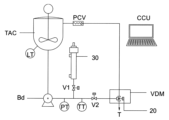
b) 以下のもので構成されている定量射出モジュール(VDM):
b.1) アーム(10)の上方に配置されて、中央制御ユニット(CCU)から受信したコマンドからこれらのアーム(10)の起動を連続的に記録し、画像のデジタル処理によって、定量射出ノズルアーム(10)の位置決めとインターロック、および計量バルブ(20)の開閉を確認する画像取得ユニット(IM);
b.2) 中央制御ユニット(CCU)から受け取ったコマンドによってアーム(10)を移動させる空気圧アクチュエータ(12)によって駆動されるレバー機構と、自由端に規定成分の量を投入する計量バルブ(20)を有し、定量射出ポンプ(Bd)によって供給タンク(TAC)に貯蔵されている規定成分を連続製造方式モジュールのタンク(T)に流す一連のアーム(10);
c) 少なくとも1つの連続製造モジュールは、回転機構(RPT)を備えており、前記回転機構(RPT)は、中央制御ユニット(CCU)によって駆動されるインデックスユニットを備えており、起動後、減速機付きモーター(Mr)によって回転するラジアルアーム(401)が取り付けられた中心軸(40)を回転し、ラジアルアーム(401)の自由端には、定量射出モジュール(VDM)によって成分が投入されるタンク(T)が配置されており、前記タンク(T)の内部構造には羽根車軸(41)と、撹拌機(411)と、排出弁(42)が配置され、前記タンク(T)は各ステーションに順次、配置される:
c.1) 混合ステーション(MS)は、モーター(M2)を備えた空気圧式昇降機構(50)と、タンク(T)の上部に位置するためのタンクシーリングカバー(51)を装備し、電動機(M2)の軸に固定されたトラクションピン(52)が、前記電動機(M2)と均質化羽根車シャフト(41)と連結し、
c.2) 連続特性調製ステーション(CAS)は、モーター(M2)を備えた空気圧式昇降機構(50)と、タンク(T)の上部に位置するためのタンクシーリングカバー(51)を装備し、電動機(M2)の軸に固定されたトラクションピン(52)が、前記電動機(M2)と、均質化羽根車シャフト(41)と、タンク(T)の排出弁(42)自動結合装置(421)によって材料調製循環ポンプ(mb1)と連結し、
中央制御ユニット(CCU)によるデータ収集のために、連続特性調製ステーション(CAS)には、連続式ラインミキサー(60)と、コリオリ力利用の質量流量、温度、粘度、密度等の多機能特性用測定器(80)が設置され、湿式色測定ユニット(100)、調製中の材料を順方向または循環タンクに戻すためまたは製品が既定の仕様に達したとき充填機の方向に流すための三方弁を備え、
g) 設定された循環流量に達すると、中央制御ユニット(CCU)は、多機能特性用測定器(80)と湿式色測定デバイス(100)によって分析データの収集を開始し、
h) 得られたデータから、ポンプで設定された材料の流量に基づいて、中央制御ユニット(CCU)は、連続式ラインミキサー(60)で連続的に投入するために必要な各成分の個々の調製量を特定し計算し、
i) 中央制御ユニット(CCU)は成分の定量射出ポンプ(Bda)の回転数を調整し、同時に連続式ラインミキサー(60)の三方弁(vt)を整合させて作動し、
j) 中央制御ユニット(CCU)の操作で、新しい分析が継続的に行われ、製品が仕様に到達するまで、繰り返し成分の流量を計算し、修正し、特性の分析と調製期間中、三方弁(vt)はタンク(T)への再循環のための整合を維持し、
c.3) 洗浄ステーション(CS)は、モーター(M2)を備えた空気圧式昇降機構(50)と、タンク(T)の上部に位置するためのタンクシーリングカバー(51)を装備し、電動機(M2)の軸に固定されたトラクションピン(52)が、前記電動機(M2)と均質化羽根車シャフト(41)と連結し、シーリングカバー(51)に設置されている溶剤ミスト噴射ノズル(130)は、洗浄用マニホールド(140)の自動バルブ(141)を通して溶剤を受け取り、タンク(T)に設置された空気圧で作動する排出弁(42)がタンク(T)の洗浄工程で使用された溶剤を除去する。 - 請求項1に記載のシステムであって、中央制御ユニット(CCU)は、タンク(T)内の投入対象成分に相当するアーム(10)を駆動し、供給タンク(TAC)に貯蔵されている成分を流すための計量バルブ(20)を整列させ、規定成分の量に達するまで、連続製造方式モジュールのタンク(T)に成分を流すことを特徴とする。
- 請求項1に記載のシステムであって、計量バルブ(20)は、定量射出ポンプ(Bd)によって供給タンク(TAC)に貯蔵されている成分を受け取る注入口(21)と、空気圧アクチュエータシリンダ(12)が後退している間に、定量射出ポンプ(Bd)によって移送された成分の全流量をタンク(T)に直接排出する投与ノズル(22)があることを特徴とする。
- 請求項3に記載のシステムであって、定量射出バルブ(20)内で空気圧アクチュエータシリンダ(12)を前進させると、供給タンク(TAC)から受け取った成分が再循環し、排出口(23)を介して供給タンク(TAC)に戻るとことを特徴とする。
- 請求項1に記載のシステムであって、定量射出モジュール(VDM)に供給する定量射出ポンプ(Bd)は、1台の電動機(M)によって駆動される2本の共有中心軸(14a)・(14b)に設置され、第2の軸(14b)は、遊星歯車減速機(131)と、スプロケットとローラチェーンのセット(130)と、変速機(133)によって、第1の軸(14a)に結合され、同期しており、軸(14a)・(14b)の回転数をカウントするデジタルエンコーダ(134)が設置されており、このデータを中央制御ユニット(CCU)に送ることを特徴とする。
- 請求項5に記載のシステムであって、各定量射出ポンプ(Bd)は、空気圧アクチュエータ(132)によって空気圧で駆動されるギアセットが設けられ、各定量射出ポンプ(Bd)をそれぞれの共有中心軸(14a)・(14b)に結合され、空気圧アクチュエータ(132)を作動させると、ポンプギア機構連結(135)の駆動アームが作動し、ポンプギア機構の送り支持具(136)が駆動され、この支持具(136)が定量射出ポンプ連結デバイス(137)を前方に押し出し、「オス」溝が定量射出ポンプ(Bd)のメス型カップリングデバイス(13)の「メス」溝と嵌合し、2つのデバイス(137)と(13)が結合し、定量射出ポンプ連結デバイス(137)は共有中心軸(14a)・(14b)に依存し、これにより軸(14a)・(14b)の回転駆動が最終的に定量射出ポンプ(Bd)に伝わることを特徴とする。
- 請求項5または請求項6に記載のシステムであって、較正ユニット(30)の下端には、定量射出ポンプ(Bd)の吐出ラインに接続するための接続口(301)が設けられ、較正ユニット(30)の内部には、定量注入式シリンジ型較正ユニット(30)の内部を保護する円筒金属(38)と、定量注入式シリンジ型較正ユニット(30)の筒として機能する非磁性円筒金属(39)が使われており、ここに2つの磁気位置センサ(34a)・(34b)が固定され、この円筒金属(39)の内部には、シールガスケット(32)を備えたピストン(31)が装備されており、前記ガスケット(32)の間には、シリンジャー(39)の本体の凹んだ部分に磁気位置センサー(34a)および(34b)を感知する磁石(33)が設置されていることを特徴とする。
- 請求項1に記載のシステムであって、電動機(M3)によって駆動される連続ラインミキサー(60)は、デッドボリュームが少なく応答時間が短い混合室(601)を備えた本体に、均質化羽根車(17)と、混合室(601)を一体的に冷却するための外部容器(602)が設けられ、前記連続ラインミキサー(60)は、混合室(601)に設置されたラジアル射出弁(61)を通して、製造中の塗料のロットの特性を調製するための成分の連続的な流れを供給することを特徴とする。
- 請求項8に記載のシステムであって、ラジアル射出弁(61)には、導入口(71)と、連続式ラインミキサー(60)の混合室(601)に結合された閉塞プラグ(72)が設けられ、前記閉塞プラグ(72)はバルブシャフト(73)に固定されており、円錐ばね(74)によって張力がかけられており、バルブシャフトの後部にはフォーク形状のシャフトロック(77)があり、シャフトロック(77)は空気圧スライド機構(75)に固定されており、投入工程中にバルブシャフト(73)を解放したいときには、エアー接続(76)に圧縮空気を入れてチャンバーを加圧することを特徴とする。
- 請求項1に記載のシステムであって、回転式タンク(T)から出てくる調製中の製品の温度調整のための熱交換器(90)が設けられており、前記熱交換器(90)は、同心円状の内筒(91)と外筒(92)に囲まれ、内筒(91)と外筒(92)の間には、熱交換器ミラー(94)に設置された流入口(93)から入った冷媒が、最初に内筒(91)の螺旋状の流路を通過して循環し、熱交換器ミラーに到達するまでの間、冷却水の流れは外筒(92)の螺旋状の流路に導かれ、そこから冷却水は熱交換器の外部ハウジング(901)を通って、再び熱交換器ミラー(94)に戻り、この経路は、温度調整中の製品が熱交換器(90)を通過する中間シリンダー(95)に対して完全に密閉されていることを特徴とする。
- 請求項1に記載のシステムであって、中央制御ユニット(CCU)に接続されたコンピュータ・コントローラ・ユニットを備えたロボットデバイス(DR)が設置され、前記ロボットデバイス(DR)は、分光光度計カップリング(103)と較正基準標準白色板を持つ間接アーム(1031)、較正基準標準黒色板を持つ間接アーム(1032)、および較正基準標準緑色板を持つ間接アーム(1033)との結合作業や、透明な水晶光学窓(102)を備えた色読み取りセル(101)との結合作業のために、空気圧シリンダー(104)によって垂直に持ち上げられたベースを装備していることを特徴とする。
- 請求項11に記載のシステムであって、湿式色測定セル(101)は、加圧に関するデータを中央制御ユニット(CCU)に送信する圧力トランスミッター(121)を備えた過圧防止安全装置(120)に接続され、この過圧防止安全装置(120)は、校正済みバネ(123)を介して自己制御されたブロック(125)を有し、圧力が上限を超えた場合、湿式色測定セル(101)が減圧され、色測定セル内を循環していた材料は、排出口(124)に接続された特別な減圧ラインに排出されることを特徴とする。
- 請求項1に記載のシステムであって、光学測定窓(102)のセルフクリーニング機構(110)は、台形型に凸部(111)を備えており、台形型に凸部(111)には、パーフルオロエラストマーブレード(112)がはめ込みされており、前記セルフクリーニング機構(110)は円錐形バネ(113)によって、測定用セル(102)の内側の面を押し付けていることを特徴とする。
- 請求項1に記載のシステムであって、洗浄用マニホールド(140)には、溶剤と窒素を装置に供給するための2つの自動バルブ(141a)・(141b)があり、溶剤と窒素の混合による高乱流ミストを高速で発生させることができるエジェクター(142)、中央制御ユニット(CCU)からの命令を受けてミストの流れを被洗浄面に導く自動分配弁(141)が設置されていることを特徴とする。
- 最終製品の特性を自動的に調製する塗料製造方法であって、請求項1記載の本発明に基づき、以下の工程を含むことを特徴とする:
a) 中央制御ユニット(CCU)に規定された成分を、定量射出モジュール(VDM)によってタンク(T)に直接投入すること、
b) 回転駆動機構(RPT)がタンク(T)を混合ステーション(MS)に配置すること、
c) 混合ステーション(MS)で前記タンク(T)の内容物を中央制御ユニット(CCU)に予め設定された一定の時間間隔で均質化すること、
d) 回転駆動機構(RPT)がタンク(T)を連続特性調製ステーション(CAS)に配置すること、
e) 空気式昇降機構(50)によって混合器のタンクシーリングカバー(51)がタンク(T)の上に降ろされ、同時にタンク底部の排出弁(42)が自動結合装置(421)を通して調製中の材料循環ポンプに結合されること、
f) タンク(T)の撹拌機モーター(41)と調製中材料循環ポンプを同時に駆動し、中央制御ユニット(CCU)に設定された循環流量に達するまで作動させること、
前記タンク(T)の内部構造には羽根車軸(41)と、撹拌機(411)と、排出弁(42)が配置され、前記タンク(T)は各ステーションに順次、配置されること、
g) 設定された循環流量に達すると、中央制御ユニット(CCU)は、多機能特性用測定器(80)と湿式色測定デバイス(100)によって分析データの収集を開始すること、
h) 得られたデータから、ポンプで設定された材料の流量に基づいて、中央制御ユニット(CCU)は、連続式ラインミキサー(60)で連続的に投入するために必要な各成分の個々の調製量を特定し計算すること、
i) 中央制御ユニット(CCU)は成分の定量射出ポンプ(Bda)の回転数を調整し、同時に連続式ラインミキサー(60)の三方弁(vt)を整合させて作動すること、
j) 中央制御ユニット(CCU)の操作で、新しい分析が継続的に行われ、製品が仕様に到達するまで、繰り返し成分の流量を計算し、修正し、特性の分析と調製期間中、三方弁(vt)はタンク(T)への再循環のための整合を維持すること、
k) 中央制御ユニット(CCU)は充填装置の三方弁(vt)充填ステーション(FM)の位置に移動させること、
l) 回転機構(RPT)がタンク(T)を洗浄ステーション(CS)と、連続調製ステーション(CAS)の位置に移動させること、
c.3) 洗浄ステーション(CS)は、モーター(M2)を備えた空気圧式昇降機構(50)と、タンク(T)の上部に位置するためのタンクシーリングカバー(51)を装備し、電動機(M2)の軸に固定されたトラクションピン(52)が、前記電動機(M2)と均質化羽根車シャフト(41)と連結し、シーリングカバー(51)に設置されている溶剤ミスト噴射ノズル(130)は、洗浄用マニホールド(140)の自動バルブ(141)を通して溶剤を受け取り、タンク(T)に設置された空気圧で作動する排出弁(42)がタンク(T)の洗浄工程で使用された溶剤を除去すること、
m) 洗浄後、回転機構(RPT)がタンク(T)を定量射出モジュール(VDM)の位置に移動させ、新しいロットを開始すること。 - 最終製品の特性を自動的に調製する塗料製造方法であって、以下を含むことを特徴とする:
a) コンピュータプログラムの命令セットからコマンドを送信する中央制御ユニット;
b) 以下の要素で構成されている定量射出モジュール(VDM):
b.1) アーム(10)の上方に配置されて、中央制御ユニット(CCU)から受信したコマンドからこれらのアーム(10)の起動を連続的に記録し、画像のデジタル処理によって、定量射出ノズルアーム(10)の位置決めとインターロック、および計量バルブ(20)の開閉を確認する画像取得ユニット(IM);
b.2) 中央制御ユニット(CCU)から受け取ったコマンドによってアーム(10)を移動させる空気圧アクチュエータ(12)によって駆動されるレバー機構と、自由端に規定成分の量を投入する計量バルブ(20)を有し、定量射出ポンプ(Bd)によって供給タンク(TAC)に貯蔵されている規定成分を連続製造方式モジュールのタンク(T)に流す一連のアーム(10);
c) 少なくとも1つの連続製造モジュールは、2つの回転ユニット(RPT1・RPT2)を備え、回転ユニット(RPT)は、それぞれ3つのタンク(T1・T2・T3)を備えており、前記回転ユニット(RPT)は、中央制御ユニット(CCU)によって駆動されるインデックスユニットを備えており、起動後、減速機付きモーター(Mr)によって回転するラジアルアーム(401)が取り付けられた中心軸(40)を回転し、ラジアルアーム(401)の自由端には、定量射出モジュール(VDM)によって成分が投入されるタンク(T)が配置され、前記タンク(T)の内部構造には羽根車軸(41)と、撹拌機(411)と、排出弁(42)が配置され、前記タンク(T)は各ステーションに順次、配置される:
c.1) 混合ステーション(MS)は、モーター(M2)を備えた空気圧式昇降機構(50)と、タンク(T)の上部に位置するためのタンクシーリングカバー(51)を装備し、電動機(M2)の軸に固定されたトラクションピン(52)が、前記電動機(M2)と均質化羽根車シャフト(41)と連結している
c.2) 連続特性調製ステーション(CAS)は、モーター(M2)を備えた空気圧式昇降機構(50)と、均質化羽根車軸(41)に結合する電動機(M2)のシャフトに固定されたトラクションピン(52)と、混合器のタンクシーリングカバー(51)に結合する定量射出ノズルヘッダー(701)を装備し、前記定量射出ノズルヘッダー(701)は、タンク(T)の内容物と、多機能特性用測定器(80)や、湿式色測定モジュール(100)の分析データに基づき、中央制御ユニット(CCU)が実施した推定値から、定量射出ポンプ(Bd)によって個別に供給される特調製要素用の射出計量バルブが設けられている
g) 設定された循環流量に達すると、中央制御ユニット(CCU)は、多機能特性用測定器(80)と湿式色測定デバイス(100)によって分析データの収集を開始する
h) 得られたデータから、ポンプで設定された材料の流量に基づいて、中央制御ユニット(CCU)は、連続式ラインミキサー(60)で連続的に投入するために必要な各成分の個々の調製量を特定し計算する
i) 中央制御ユニット(CCU)は成分の定量射出ポンプ(Bda)の回転数を調整し、同時に連続式ラインミキサー(60)の三方弁(vt)を整合させて作動する
j) 中央制御ユニット(CCU)の操作で、新しい分析が継続的に行われ、製品が仕様に到達するまで、繰り返し成分の流量を計算し、修正し、特性の分析と調製期間中、三方弁(vt)はタンク(T)への再循環のための整合を維持する
c.3) 洗浄ステーション(CS)は、モーター(M2)を備えた空気圧式昇降機構(50)と、タンク(T)の上部に位置するためのタンクシーリングカバー(51)を装備し、電動機(M2)の軸に固定されたトラクションピン(52)が、前記電動機(M2)と均質化羽根車シャフト(41)と連結しており、シーリングカバー(51)に設置されている溶剤ミスト噴射ノズル(130)は、洗浄用マニホールド(140)の自動バルブ(141)を通して溶剤を受け取り、タンク(T)に設置された空気圧で作動する排出弁(42)がタンク(T)の洗浄工程で使用された溶剤を除去する。 - 最終製品の特性を自動的に調製する塗料製造方法であって、請求項1で説明するシステムを使用することで、以下の工程を含むことを特徴とする:
a) 中央制御ユニット(CCU)に規定された成分を、定量射出モジュール(VDM)によってタンク(T)に直接投入すること、
b) 回転駆動機構(RPT)がタンク(T)を混合ステーション(MS)に配置すること、
c) 混合ステーション(MS)で前記タンク(T)の内容物を中央制御ユニット(CCU)に予め設定された一定の時間間隔で均質化すること、
d) 回転駆動機構(RPT)がタンク(T)を連続特性調製ステーション(CAS)に配置すること、
e) 空気式昇降機構(50)によって混合器のタンクシーリングカバー(51)がタンク(T)の上に降ろされ、同時にタンク底部の排出弁(42)が自動結合装置(421)を通して調製中の材料循環ポンプに結合されること、
前記タンク(T)の内部構造には羽根車軸(41)と、撹拌機(411)と、排出弁(42)が配置され、前記タンク(T)は各ステーションに順次、配置されること、
f) タンク(T)の撹拌機モーター(41)と調製中材料循環ポンプを同時に駆動し、中央制御ユニット(CCU)に設定された循環流量に達するまで作動させること、
g) 設定された循環流量に達すると、中央制御ユニット(CCU)は、多機能特性用測定器(80)と湿式色測定デバイス(100)によって分析データの収集を開始すること、
h) 得られたデータから、ポンプで設定された材料の流量に基づいて、中央制御ユニット(CCU)は、連続式ラインミキサー(60)で連続的に投入するために必要な各成分の個々の調製量を特定し計算すること、
i) 中央制御ユニット(CCU)は成分の定量射出ポンプ(Bda)の回転数を調整し、同時に連続式ラインミキサー(60)の三方弁(vt)を整合させて作動すること、
j) 中央制御ユニット(CCU)の操作で、新しい分析が継続的に行われ、製品が仕様に到達するまで、繰り返し成分の流量を計算し、修正し、特性の分析と調製期間中、三方弁(vt)はタンク(T)への再循環のための整合を維持すること、
k) 中央制御ユニット(CCU)は充填装置の三方弁(vt)充填ステーション(FM)の位置に移動させること、
l) 回転機構(RPT)がタンク(T)を洗浄ステーション(CS)と、連続調製ステーション(CAS)の位置に移動させること、
c.3) 洗浄ステーション(CS)は、モーター(M2)を備えた空気圧式昇降機構(50)と、タンク(T)の上部に位置するためのタンクシーリングカバー(51)を装備し、電動機(M2)の軸に固定されたトラクションピン(52)が、前記電動機(M2)と均質化羽根車シャフト(41)と連結し、シーリングカバー(51)に設置されている溶剤ミスト噴射ノズル(130)は、洗浄用マニホールド(140)の自動バルブ(141)を通して溶剤を受け取り、タンク(T)に設置された空気圧で作動する排出弁(42)がタンク(T)の洗浄工程で使用された溶剤を除去すること、
m) 洗浄後、回転機構(RPT)がタンク(T)を定量射出モジュール(VDM)の位置に移動させ、新しいロットを開始すること。
Applications Claiming Priority (3)
| Application Number | Priority Date | Filing Date | Title |
|---|---|---|---|
| BRBR1020190050470 | 2019-03-15 | ||
| BR102019005047-0A BR102019005047B1 (pt) | 2019-03-15 | 2019-03-15 | Sistema de produção de tinta com auto-ajuste automático de propriedades do produto final e respectivo método |
| PCT/BR2020/050084 WO2020186323A1 (pt) | 2019-03-15 | 2020-03-12 | Sistema de produção de tinta com auto-ajuste automático de propriedades do produto final e respectivo método |
Publications (2)
| Publication Number | Publication Date |
|---|---|
| JP2022525372A JP2022525372A (ja) | 2022-05-12 |
| JP7581317B2 true JP7581317B2 (ja) | 2024-11-12 |
Family
ID=72519424
Family Applications (1)
| Application Number | Title | Priority Date | Filing Date |
|---|---|---|---|
| JP2022502314A Active JP7581317B2 (ja) | 2019-03-15 | 2020-03-12 | 最終製品特性の自動調整を備えた塗料製造システムとその方法 |
Country Status (6)
| Country | Link |
|---|---|
| US (1) | US12220676B2 (ja) |
| EP (1) | EP3940480B1 (ja) |
| JP (1) | JP7581317B2 (ja) |
| BR (1) | BR102019005047B1 (ja) |
| CA (1) | CA3133481A1 (ja) |
| WO (1) | WO2020186323A1 (ja) |
Families Citing this family (10)
| Publication number | Priority date | Publication date | Assignee | Title |
|---|---|---|---|---|
| WO2022037062A1 (zh) * | 2020-08-17 | 2022-02-24 | 武汉钢铁有限公司 | 在线色差检测系统及检测方法 |
| CN113274904B (zh) * | 2021-03-19 | 2024-12-03 | 绍兴前进齿轮箱有限公司 | 一种用于垃圾处理机的搅拌轴部件 |
| CN113786776A (zh) * | 2021-08-31 | 2021-12-14 | 湖北卡乐尔新材料科技有限公司 | 一种硅酮胶用色浆的生产设备及生产方法 |
| CN114870679B (zh) * | 2022-06-14 | 2024-06-07 | 上海汉伟医疗器械有限公司 | 一种恒温脂肪乳化装置及其脂肪乳化方法 |
| CN115337848A (zh) * | 2022-08-19 | 2022-11-15 | 叶俊杰 | 一种环境检测装置及环境调节设备 |
| DE102023112375A1 (de) * | 2023-05-10 | 2024-11-14 | Fricke Abfülltechnik GmbH & Co. KG | Mischbehälter |
| CN117358088A (zh) * | 2023-10-10 | 2024-01-09 | 胡世弘 | 一种油墨组合物及其制备方法 |
| CN118819209B (zh) * | 2024-09-20 | 2025-01-21 | 湖州盛世华骏新型材料股份有限公司 | 一种醋丙乳液制备温度调节方法及系统 |
| EP4721848A1 (en) * | 2024-10-04 | 2026-04-08 | Dromont S.p.A. | A system and method for producing paints in batches |
| CN120169212B (zh) * | 2025-05-20 | 2025-08-22 | 福建初日涂料科技有限公司 | 一种环保水性漆生产用精确调色装置及调色方法 |
Citations (3)
| Publication number | Priority date | Publication date | Assignee | Title |
|---|---|---|---|---|
| JP2002514971A (ja) | 1998-02-13 | 2002-05-21 | レナー ド ポント ティンタス オートモーティバス エ インダストリアイズ エスエイ | 自動車用などの塗料の製造 |
| JP2008111116A (ja) | 2007-10-12 | 2008-05-15 | Nippon Paint Co Ltd | 塗料液のコンピュータ調色方法とこの方法を用いた塗料の製造方法 |
| JP2015529546A (ja) | 2012-07-13 | 2015-10-08 | ピーピージー・インダストリーズ・オハイオ・インコーポレイテッドPPG Industries Ohio,Inc. | コーティング組成物の自動化された生成、塗布および評価のためのシステムおよび方法 |
Family Cites Families (12)
| Publication number | Priority date | Publication date | Assignee | Title |
|---|---|---|---|---|
| DE3608038C1 (de) * | 1986-03-11 | 1987-07-09 | Klaus Burk | Mischvorrichtung |
| JPH0698879B2 (ja) * | 1988-08-27 | 1994-12-07 | 日本ペイント株式会社 | 液状色剤の自動調色装置と調色方法 |
| JPH10296150A (ja) * | 1997-04-28 | 1998-11-10 | Nichiha Corp | 建築板塗装装置の噴射異常判定システム |
| IT1298391B1 (it) | 1997-12-30 | 2000-01-05 | Corob Spa | Macchina dispensatrice per erogazione dosata ed omogeneizzazione in continuo di prodotti finiti vernicianti. |
| BR9801134A (pt) * | 1998-03-26 | 2006-11-14 | Renner Herrmann Sa | aparelho e processo para preparação contìnua de um fluido com ajuste automático das suas propriedades |
| ITBO20020774A1 (it) | 2002-12-10 | 2004-06-11 | Valpaint S R L | Apparecchiatura per il dosaggio di pigmenti colorati |
| DE20307083U1 (de) | 2003-05-07 | 2003-08-14 | TECHKON GmbH, 61462 Königstein | Vorrichtung zum Herstellen einer vorgebbaren Menge einer sonderfarbigen Farbflüssigkeit |
| US10245568B2 (en) * | 2014-05-13 | 2019-04-02 | Luca Drocco | Automated system to associate an agitator with a respective container for containing fluid and method thereof |
| US9393536B2 (en) | 2014-11-20 | 2016-07-19 | Dedoes Industries, Inc. | Paint dispensing apparatus |
| US9643134B1 (en) | 2016-07-12 | 2017-05-09 | Mazzei Injector Company, Llc | Proportionate automated blending system for aqueous mixtures |
| CN207899388U (zh) | 2017-12-13 | 2018-09-25 | 舟山市奥力士制漆有限公司 | 一种自动配料的涂料生产设备 |
| BR102018073022B1 (pt) | 2018-11-08 | 2021-08-10 | Rogério Baptista Auad | Equipamento e método de análise de um fluído |
-
2019
- 2019-03-15 BR BR102019005047-0A patent/BR102019005047B1/pt active IP Right Grant
-
2020
- 2020-03-12 WO PCT/BR2020/050084 patent/WO2020186323A1/pt not_active Ceased
- 2020-03-12 CA CA3133481A patent/CA3133481A1/en active Pending
- 2020-03-12 JP JP2022502314A patent/JP7581317B2/ja active Active
- 2020-03-12 US US17/439,651 patent/US12220676B2/en active Active
- 2020-03-12 EP EP20773341.1A patent/EP3940480B1/en active Active
Patent Citations (3)
| Publication number | Priority date | Publication date | Assignee | Title |
|---|---|---|---|---|
| JP2002514971A (ja) | 1998-02-13 | 2002-05-21 | レナー ド ポント ティンタス オートモーティバス エ インダストリアイズ エスエイ | 自動車用などの塗料の製造 |
| JP2008111116A (ja) | 2007-10-12 | 2008-05-15 | Nippon Paint Co Ltd | 塗料液のコンピュータ調色方法とこの方法を用いた塗料の製造方法 |
| JP2015529546A (ja) | 2012-07-13 | 2015-10-08 | ピーピージー・インダストリーズ・オハイオ・インコーポレイテッドPPG Industries Ohio,Inc. | コーティング組成物の自動化された生成、塗布および評価のためのシステムおよび方法 |
Non-Patent Citations (1)
| Title |
|---|
| Putting cameras in the loop,2013年08月12日,URL:https://www.motioncontroltips.com/putting-cameras-in-the-loop |
Also Published As
| Publication number | Publication date |
|---|---|
| US12220676B2 (en) | 2025-02-11 |
| JP2022525372A (ja) | 2022-05-12 |
| BR102019005047B1 (pt) | 2021-04-13 |
| BR102019005047A2 (pt) | 2020-10-06 |
| EP3940480B1 (en) | 2025-01-29 |
| EP3940480A4 (en) | 2022-12-14 |
| US20220161210A1 (en) | 2022-05-26 |
| EP3940480C0 (en) | 2025-01-29 |
| EP3940480A1 (en) | 2022-01-19 |
| CA3133481A1 (en) | 2020-09-24 |
| WO2020186323A1 (pt) | 2020-09-24 |
Similar Documents
| Publication | Publication Date | Title |
|---|---|---|
| JP7581317B2 (ja) | 最終製品特性の自動調整を備えた塗料製造システムとその方法 | |
| JP7470815B2 (ja) | 搬送装置および調色装置 | |
| US3670785A (en) | Method and apparatus for tinting paint | |
| CN1150056C (zh) | 用于生产汽车漆和其它油漆的连续自动化工艺 | |
| US5474211A (en) | Method of dispensing materials with improved accuracy | |
| CA2107523C (en) | Plural component delivery system | |
| CA1209669A (en) | Process for making paints | |
| US5460297A (en) | Paint tinting apparatus | |
| RU2731588C1 (ru) | Способ и смесительная установка для основанного на дозированных замесах приготовления текучего покровного материала | |
| CA1290744C (en) | Process and an apparatus for mixing substances | |
| WO2020057458A1 (zh) | 汽车修补漆体积配色方法、定体积注出装置及自动配色装置 | |
| CN110171199A (zh) | 一种自动供墨并具备自动清洗功能的供墨系统及实现方法 | |
| EP0719623B1 (en) | Method and apparatus for color matching of sealants | |
| JPH0698879B2 (ja) | 液状色剤の自動調色装置と調色方法 | |
| US20260097374A1 (en) | System and method for producing paints in batches | |
| WO2012014023A1 (en) | Apparatus for metering and delivering painting products | |
| CN111760525A (zh) | 一种乳胶漆调色设备及调色方法 | |
| CN110898755A (zh) | 汽车修补漆体积配色方法及汽车修补漆定体积注出装置 | |
| KR20230001711A (ko) | 스마트 하이브리드형 충진 시스템 및 충진 방법 | |
| Turner | The Automated Drug Room. | |
| HK1071905A (en) | Production of automotive and other paints |
Legal Events
| Date | Code | Title | Description |
|---|---|---|---|
| A521 | Request for written amendment filed |
Free format text: JAPANESE INTERMEDIATE CODE: A821 Effective date: 20230310 |
|
| A621 | Written request for application examination |
Free format text: JAPANESE INTERMEDIATE CODE: A621 Effective date: 20230310 |
|
| RD02 | Notification of acceptance of power of attorney |
Free format text: JAPANESE INTERMEDIATE CODE: A7422 Effective date: 20230310 |
|
| A521 | Request for written amendment filed |
Free format text: JAPANESE INTERMEDIATE CODE: A821 Effective date: 20230311 |
|
| RD04 | Notification of resignation of power of attorney |
Free format text: JAPANESE INTERMEDIATE CODE: A7424 Effective date: 20230410 |
|
| A977 | Report on retrieval |
Free format text: JAPANESE INTERMEDIATE CODE: A971007 Effective date: 20231208 |
|
| A131 | Notification of reasons for refusal |
Free format text: JAPANESE INTERMEDIATE CODE: A131 Effective date: 20240130 |
|
| A601 | Written request for extension of time |
Free format text: JAPANESE INTERMEDIATE CODE: A601 Effective date: 20240426 |
|
| A521 | Request for written amendment filed |
Free format text: JAPANESE INTERMEDIATE CODE: A523 Effective date: 20240628 |
|
| TRDD | Decision of grant or rejection written | ||
| A01 | Written decision to grant a patent or to grant a registration (utility model) |
Free format text: JAPANESE INTERMEDIATE CODE: A01 Effective date: 20241001 |
|
| A61 | First payment of annual fees (during grant procedure) |
Free format text: JAPANESE INTERMEDIATE CODE: A61 Effective date: 20241030 |
|
| R150 | Certificate of patent or registration of utility model |
Ref document number: 7581317 Country of ref document: JP Free format text: JAPANESE INTERMEDIATE CODE: R150 |