JP7581317B2 - Coating production system with automatic adjustment of final product properties and method thereof - Google Patents
Coating production system with automatic adjustment of final product properties and method thereof Download PDFInfo
- Publication number
- JP7581317B2 JP7581317B2 JP2022502314A JP2022502314A JP7581317B2 JP 7581317 B2 JP7581317 B2 JP 7581317B2 JP 2022502314 A JP2022502314 A JP 2022502314A JP 2022502314 A JP2022502314 A JP 2022502314A JP 7581317 B2 JP7581317 B2 JP 7581317B2
- Authority
- JP
- Japan
- Prior art keywords
- tank
- ccu
- control unit
- central control
- station
- Prior art date
- Legal status (The legal status is an assumption and is not a legal conclusion. Google has not performed a legal analysis and makes no representation as to the accuracy of the status listed.)
- Active
Links
Images

Classifications
-
- G—PHYSICS
- G05—CONTROLLING; REGULATING
- G05D—SYSTEMS FOR CONTROLLING OR REGULATING NON-ELECTRIC VARIABLES
- G05D11/00—Control of flow ratio
- G05D11/02—Controlling ratio of two or more flows of fluid or fluent material
- G05D11/13—Controlling ratio of two or more flows of fluid or fluent material characterised by the use of electric means
- G05D11/135—Controlling ratio of two or more flows of fluid or fluent material characterised by the use of electric means by sensing at least one property of the mixture
- G05D11/136—Controlling ratio of two or more flows of fluid or fluent material characterised by the use of electric means by sensing at least one property of the mixture by sensing the viscosity
-
- B—PERFORMING OPERATIONS; TRANSPORTING
- B01—PHYSICAL OR CHEMICAL PROCESSES OR APPARATUS IN GENERAL
- B01F—MIXING, e.g. DISSOLVING, EMULSIFYING OR DISPERSING
- B01F33/00—Other mixers; Mixing plants; Combinations of mixers
- B01F33/80—Mixing plants; Combinations of mixers
-
- B—PERFORMING OPERATIONS; TRANSPORTING
- B01—PHYSICAL OR CHEMICAL PROCESSES OR APPARATUS IN GENERAL
- B01F—MIXING, e.g. DISSOLVING, EMULSIFYING OR DISPERSING
- B01F25/00—Flow mixers; Mixers for falling materials, e.g. solid particles
- B01F25/50—Circulation mixers, e.g. wherein at least part of the mixture is discharged from and reintroduced into a receptacle
- B01F25/53—Circulation mixers, e.g. wherein at least part of the mixture is discharged from and reintroduced into a receptacle in which the mixture is discharged from and reintroduced into a receptacle through a recirculation tube, into which an additional component is introduced
-
- B—PERFORMING OPERATIONS; TRANSPORTING
- B01—PHYSICAL OR CHEMICAL PROCESSES OR APPARATUS IN GENERAL
- B01F—MIXING, e.g. DISSOLVING, EMULSIFYING OR DISPERSING
- B01F27/00—Mixers with rotary stirring devices in fixed receptacles; Kneaders
- B01F27/05—Stirrers
- B01F27/11—Stirrers characterised by the configuration of the stirrers
- B01F27/115—Stirrers characterised by the configuration of the stirrers comprising discs or disc-like elements essentially perpendicular to the stirrer shaft axis
- B01F27/1152—Stirrers characterised by the configuration of the stirrers comprising discs or disc-like elements essentially perpendicular to the stirrer shaft axis with separate elements other than discs fixed on the discs, e.g. vanes fixed on the discs
-
- B—PERFORMING OPERATIONS; TRANSPORTING
- B01—PHYSICAL OR CHEMICAL PROCESSES OR APPARATUS IN GENERAL
- B01F—MIXING, e.g. DISSOLVING, EMULSIFYING OR DISPERSING
- B01F27/00—Mixers with rotary stirring devices in fixed receptacles; Kneaders
- B01F27/80—Mixers with rotary stirring devices in fixed receptacles; Kneaders with stirrers rotating about a substantially vertical axis
- B01F27/88—Mixers with rotary stirring devices in fixed receptacles; Kneaders with stirrers rotating about a substantially vertical axis with a separate receptacle-stirrer unit that is adapted to be coupled to a drive mechanism
-
- B—PERFORMING OPERATIONS; TRANSPORTING
- B01—PHYSICAL OR CHEMICAL PROCESSES OR APPARATUS IN GENERAL
- B01F—MIXING, e.g. DISSOLVING, EMULSIFYING OR DISPERSING
- B01F33/00—Other mixers; Mixing plants; Combinations of mixers
- B01F33/80—Mixing plants; Combinations of mixers
- B01F33/834—Mixing in several steps, e.g. successive steps
-
- B—PERFORMING OPERATIONS; TRANSPORTING
- B01—PHYSICAL OR CHEMICAL PROCESSES OR APPARATUS IN GENERAL
- B01F—MIXING, e.g. DISSOLVING, EMULSIFYING OR DISPERSING
- B01F33/00—Other mixers; Mixing plants; Combinations of mixers
- B01F33/80—Mixing plants; Combinations of mixers
- B01F33/84—Mixing plants with mixing receptacles receiving material dispensed from several component receptacles, e.g. paint tins
- B01F33/841—Mixing plants with mixing receptacles receiving material dispensed from several component receptacles, e.g. paint tins with component receptacles fixed in a circular configuration on a horizontal table, e.g. the table being able to be indexed about a vertical axis
-
- B—PERFORMING OPERATIONS; TRANSPORTING
- B01—PHYSICAL OR CHEMICAL PROCESSES OR APPARATUS IN GENERAL
- B01F—MIXING, e.g. DISSOLVING, EMULSIFYING OR DISPERSING
- B01F33/00—Other mixers; Mixing plants; Combinations of mixers
- B01F33/80—Mixing plants; Combinations of mixers
- B01F33/84—Mixing plants with mixing receptacles receiving material dispensed from several component receptacles, e.g. paint tins
- B01F33/846—Mixing plants with mixing receptacles receiving material dispensed from several component receptacles, e.g. paint tins using stored recipes for determining the composition of the mixture to be produced, i.e. for determining the amounts of the basic components to be dispensed from the component receptacles
-
- B—PERFORMING OPERATIONS; TRANSPORTING
- B01—PHYSICAL OR CHEMICAL PROCESSES OR APPARATUS IN GENERAL
- B01F—MIXING, e.g. DISSOLVING, EMULSIFYING OR DISPERSING
- B01F33/00—Other mixers; Mixing plants; Combinations of mixers
- B01F33/80—Mixing plants; Combinations of mixers
- B01F33/85—Mixing plants with mixing receptacles or mixing tools that can be indexed into different working positions
-
- B—PERFORMING OPERATIONS; TRANSPORTING
- B01—PHYSICAL OR CHEMICAL PROCESSES OR APPARATUS IN GENERAL
- B01F—MIXING, e.g. DISSOLVING, EMULSIFYING OR DISPERSING
- B01F35/00—Accessories for mixers; Auxiliary operations or auxiliary devices; Parts or details of general application
- B01F35/10—Maintenance of mixers
- B01F35/145—Washing or cleaning mixers not provided for in other groups in this subclass; Inhibiting build-up of material on machine parts using other means
- B01F35/1452—Washing or cleaning mixers not provided for in other groups in this subclass; Inhibiting build-up of material on machine parts using other means using fluids
-
- B—PERFORMING OPERATIONS; TRANSPORTING
- B01—PHYSICAL OR CHEMICAL PROCESSES OR APPARATUS IN GENERAL
- B01F—MIXING, e.g. DISSOLVING, EMULSIFYING OR DISPERSING
- B01F35/00—Accessories for mixers; Auxiliary operations or auxiliary devices; Parts or details of general application
- B01F35/181—Preventing generation of dust or dirt; Sieves; Filters
- B01F35/186—Preventing generation of dust or dirt; Sieves; Filters using splash guards in mixers for avoiding dirt or projection of material
-
- B—PERFORMING OPERATIONS; TRANSPORTING
- B01—PHYSICAL OR CHEMICAL PROCESSES OR APPARATUS IN GENERAL
- B01F—MIXING, e.g. DISSOLVING, EMULSIFYING OR DISPERSING
- B01F35/00—Accessories for mixers; Auxiliary operations or auxiliary devices; Parts or details of general application
- B01F35/20—Measuring; Control or regulation
- B01F35/21—Measuring
- B01F35/211—Measuring of the operational parameters
- B01F35/2117—Weight
-
- B—PERFORMING OPERATIONS; TRANSPORTING
- B01—PHYSICAL OR CHEMICAL PROCESSES OR APPARATUS IN GENERAL
- B01F—MIXING, e.g. DISSOLVING, EMULSIFYING OR DISPERSING
- B01F35/00—Accessories for mixers; Auxiliary operations or auxiliary devices; Parts or details of general application
- B01F35/20—Measuring; Control or regulation
- B01F35/21—Measuring
- B01F35/213—Measuring of the properties of the mixtures, e.g. temperature, density or colour
-
- B—PERFORMING OPERATIONS; TRANSPORTING
- B01—PHYSICAL OR CHEMICAL PROCESSES OR APPARATUS IN GENERAL
- B01F—MIXING, e.g. DISSOLVING, EMULSIFYING OR DISPERSING
- B01F35/00—Accessories for mixers; Auxiliary operations or auxiliary devices; Parts or details of general application
- B01F35/71—Feed mechanisms
- B01F35/717—Feed mechanisms characterised by the means for feeding the components to the mixer
- B01F35/7176—Feed mechanisms characterised by the means for feeding the components to the mixer using pumps
-
- B—PERFORMING OPERATIONS; TRANSPORTING
- B01—PHYSICAL OR CHEMICAL PROCESSES OR APPARATUS IN GENERAL
- B01F—MIXING, e.g. DISSOLVING, EMULSIFYING OR DISPERSING
- B01F35/00—Accessories for mixers; Auxiliary operations or auxiliary devices; Parts or details of general application
- B01F35/75—Discharge mechanisms
- B01F35/754—Discharge mechanisms characterised by the means for discharging the components from the mixer
- B01F35/7547—Discharge mechanisms characterised by the means for discharging the components from the mixer using valves, gates, orifices or openings
-
- F—MECHANICAL ENGINEERING; LIGHTING; HEATING; WEAPONS; BLASTING
- F28—HEAT EXCHANGE IN GENERAL
- F28D—HEAT-EXCHANGE APPARATUS, NOT PROVIDED FOR IN ANOTHER SUBCLASS, IN WHICH THE HEAT-EXCHANGE MEDIA DO NOT COME INTO DIRECT CONTACT
- F28D7/00—Heat-exchange apparatus having stationary tubular conduit assemblies for both heat-exchange media, the media being in contact with different sides of a conduit wall
- F28D7/005—Heat-exchange apparatus having stationary tubular conduit assemblies for both heat-exchange media, the media being in contact with different sides of a conduit wall the conduits for only one medium being tubes having bent portions or being assembled from bent tubes or being tubes having a toroidal configuration
-
- G—PHYSICS
- G05—CONTROLLING; REGULATING
- G05B—CONTROL OR REGULATING SYSTEMS IN GENERAL; FUNCTIONAL ELEMENTS OF SUCH SYSTEMS; MONITORING OR TESTING ARRANGEMENTS FOR SUCH SYSTEMS OR ELEMENTS
- G05B19/00—Program-control systems
- G05B19/02—Program-control systems electric
- G05B19/04—Program control other than numerical control, i.e. in sequence controllers or logic controllers
- G05B19/041—Function-oriented details
-
- G—PHYSICS
- G05—CONTROLLING; REGULATING
- G05B—CONTROL OR REGULATING SYSTEMS IN GENERAL; FUNCTIONAL ELEMENTS OF SUCH SYSTEMS; MONITORING OR TESTING ARRANGEMENTS FOR SUCH SYSTEMS OR ELEMENTS
- G05B19/00—Program-control systems
- G05B19/02—Program-control systems electric
- G05B19/18—Numerical control [NC], i.e. automatically operating machines, in particular machine tools, e.g. in a manufacturing environment, so as to execute positioning, movement or co-ordinated operations by means of program data in numerical form
- G05B19/19—Numerical control [NC], i.e. automatically operating machines, in particular machine tools, e.g. in a manufacturing environment, so as to execute positioning, movement or co-ordinated operations by means of program data in numerical form characterised by positioning or contouring control systems, e.g. to control position from one programmed point to another or to control movement along a programmed continuous path
- G05B19/27—Numerical control [NC], i.e. automatically operating machines, in particular machine tools, e.g. in a manufacturing environment, so as to execute positioning, movement or co-ordinated operations by means of program data in numerical form characterised by positioning or contouring control systems, e.g. to control position from one programmed point to another or to control movement along a programmed continuous path using an absolute digital measuring device
- G05B19/29—Numerical control [NC], i.e. automatically operating machines, in particular machine tools, e.g. in a manufacturing environment, so as to execute positioning, movement or co-ordinated operations by means of program data in numerical form characterised by positioning or contouring control systems, e.g. to control position from one programmed point to another or to control movement along a programmed continuous path using an absolute digital measuring device for point-to-point control
-
- G—PHYSICS
- G05—CONTROLLING; REGULATING
- G05D—SYSTEMS FOR CONTROLLING OR REGULATING NON-ELECTRIC VARIABLES
- G05D11/00—Control of flow ratio
- G05D11/02—Controlling ratio of two or more flows of fluid or fluent material
- G05D11/13—Controlling ratio of two or more flows of fluid or fluent material characterised by the use of electric means
- G05D11/131—Controlling ratio of two or more flows of fluid or fluent material characterised by the use of electric means by measuring the values related to the quantity of the individual components
- G05D11/132—Controlling ratio of two or more flows of fluid or fluent material characterised by the use of electric means by measuring the values related to the quantity of the individual components by controlling the flow of the individual components
-
- G—PHYSICS
- G05—CONTROLLING; REGULATING
- G05D—SYSTEMS FOR CONTROLLING OR REGULATING NON-ELECTRIC VARIABLES
- G05D11/00—Control of flow ratio
- G05D11/02—Controlling ratio of two or more flows of fluid or fluent material
- G05D11/13—Controlling ratio of two or more flows of fluid or fluent material characterised by the use of electric means
- G05D11/135—Controlling ratio of two or more flows of fluid or fluent material characterised by the use of electric means by sensing at least one property of the mixture
- G05D11/137—Controlling ratio of two or more flows of fluid or fluent material characterised by the use of electric means by sensing at least one property of the mixture by sensing the density of the mixture
-
- G—PHYSICS
- G05—CONTROLLING; REGULATING
- G05D—SYSTEMS FOR CONTROLLING OR REGULATING NON-ELECTRIC VARIABLES
- G05D7/00—Control of flow
- G05D7/06—Control of flow characterised by the use of electric means
- G05D7/0617—Control of flow characterised by the use of electric means specially adapted for fluid materials
- G05D7/0629—Control of flow characterised by the use of electric means specially adapted for fluid materials characterised by the type of regulator means
- G05D7/0635—Control of flow characterised by the use of electric means specially adapted for fluid materials characterised by the type of regulator means by action on throttling means
-
- G—PHYSICS
- G06—COMPUTING OR CALCULATING; COUNTING
- G06T—IMAGE DATA PROCESSING OR GENERATION, IN GENERAL
- G06T7/00—Image analysis
- G06T7/70—Determining position or orientation of objects or cameras
-
- B—PERFORMING OPERATIONS; TRANSPORTING
- B01—PHYSICAL OR CHEMICAL PROCESSES OR APPARATUS IN GENERAL
- B01F—MIXING, e.g. DISSOLVING, EMULSIFYING OR DISPERSING
- B01F2101/00—Mixing characterised by the nature of the mixed materials or by the application field
- B01F2101/30—Mixing paints or paint ingredients, e.g. pigments, dyes, colours, lacquers or enamel
-
- G—PHYSICS
- G05—CONTROLLING; REGULATING
- G05B—CONTROL OR REGULATING SYSTEMS IN GENERAL; FUNCTIONAL ELEMENTS OF SUCH SYSTEMS; MONITORING OR TESTING ARRANGEMENTS FOR SUCH SYSTEMS OR ELEMENTS
- G05B2219/00—Program-control systems
- G05B2219/30—Nc systems
- G05B2219/43—Speed, acceleration, deceleration control ADC
- G05B2219/43193—Variable slope speed steps as function of position, pulse pump controller
-
- G—PHYSICS
- G06—COMPUTING OR CALCULATING; COUNTING
- G06T—IMAGE DATA PROCESSING OR GENERATION, IN GENERAL
- G06T2207/00—Indexing scheme for image analysis or image enhancement
- G06T2207/30—Subject of image; Context of image processing
- G06T2207/30108—Industrial image inspection
Landscapes
- Chemical Kinetics & Catalysis (AREA)
- Chemical & Material Sciences (AREA)
- Engineering & Computer Science (AREA)
- Physics & Mathematics (AREA)
- General Physics & Mathematics (AREA)
- Automation & Control Theory (AREA)
- General Engineering & Computer Science (AREA)
- Mechanical Engineering (AREA)
- Thermal Sciences (AREA)
- Manufacturing & Machinery (AREA)
- Human Computer Interaction (AREA)
- Computer Vision & Pattern Recognition (AREA)
- Theoretical Computer Science (AREA)
- Accessories For Mixers (AREA)
- Paints Or Removers (AREA)
- Application Of Or Painting With Fluid Materials (AREA)
Description
本発明の特許は、事前に調製することなく顔料ペーストとバインダーから製造される塗料生産システムについて説明している。これは、塗料の特性(色、粘度、密度など)を読み取り、自動調整するためのユニットを備えており、製品の特性に必要な補正パラメータを提供することで、演算処理ユニットが連続的に、事前に確立された仕様に従って塗料のロットを自動的に調製することができる。 The present patent describes a paint production system in which paint is produced from pigment paste and binder without prior preparation. It comprises a unit for reading and automatically adjusting the paint properties (color, viscosity, density, etc.) and providing the necessary correction parameters for the product properties, allowing a processing unit to continuously and automatically prepare a batch of paint according to pre-established specifications.
塗料とは、液体、ペースト状、または固体の顔料組成物で、供給された状態または希釈後の状態で所定の表面に薄い層(フィルム)を塗布すると、一定時間後に固体の着色された半透明または不透明なフィルムに変換されるものと定義することができる。 A paint may be defined as a liquid, pasty, or solid pigment composition which, when applied in a thin layer (film) to a given surface, either as supplied or after dilution, is transformed after a certain period of time into a solid, pigmented, translucent or opaque film.
塗料の主な成分は以下の通りである。(a) 樹脂:通常、半透明または透明の媒体で、主な機能は塗膜の基材への付着を促進することであり、顔料の濡れ性・光沢・耐薬品性・物理的耐性なども担っている。(b) 顔料およびフィラー: 発色・塗膜の不透明性・耐放射線性・光学的特性などを促進する。(c) 添加剤:フィルムに物理的・化学的・レオロジー的な特性を与える。(d) 溶剤または希釈剤:基本的には、基板上の塗料の粘度と適用性の特性を調製するために使用され、このプロセスの最後に蒸発し、形成されたフィルムの硬化/乾燥を可能にする。 The main components of a paint are: (a) Resins: Usually a translucent or transparent medium whose main function is to promote adhesion of the paint film to the substrate and also provide pigment wetting, gloss, chemical resistance, physical resistance, etc. (b) Pigments and fillers: Promote color development, opacity of the film, radiation resistance, optical properties, etc. (c) Additives: Provide physical, chemical and rheological properties to the film. (d) Solvents or diluents: Basically used to adjust the viscosity and application properties of the paint on the substrate and evaporate at the end of this process, allowing the curing/drying of the film formed.
顔料は、染料とは異なり、微細に分割された固体物質で実質的に溶媒には溶解しない。これは塗料調製時、色や不透明度、その他の特殊性をもたらす目的で使用されるものである。つまり、塗料の光学的特性や、そこに配合される製品の特性を変更する目的で使用される。適切な顔料であることを特徴付ける特性は、再現する色を取得できる能力があることで、顔料を特徴付ける重要な特性は、模倣する色を取得する能力である。それらの存在は、不透明度を得るためにも必要な場合があるからで、なぜならほとんどの場合、塗料はそれらが塗布される表面を覆うために使用されるからである。 Pigments, unlike dyes, are finely divided solid substances that are practically insoluble in solvents. They are used in paint preparations to impart color, opacity, and other special properties, i.e. to modify the optical properties of the paint and the properties of the product in which they are incorporated. The defining characteristic of a pigment is its ability to obtain the color it reproduces, while the important defining characteristic of pigments is their ability to obtain the color it mimics, since their presence may also be necessary to obtain opacity, since in most cases paints are used to cover the surface to which they are applied.
世界の塗料製造工程において、オートメーション化のレベルはまだまだ低く、ほとんどの場合、「トレイ」や「タンク」を使って塗料をまとめて一度に製造している。 The level of automation in paint manufacturing processes around the world is still low, and in most cases paint is produced in bulk at one time using "trays" or "tanks."
生産プロセスに関しては、基本的に2つの塗料製造概念が存在する。 Regarding the production process, there are basically two paint manufacturing concepts:
「機械塗料」と呼ばれる製造コンセプトでは、製造される塗料に使用されるすべての原材料(顔料・フィラー・樹脂・溶媒・添加剤)がトレイに直接注入され、混合されてから混合器に運ばれ、顔料が分散される。その目的は光沢・被覆率・不透明度などの特性に必要な「細かさ」を得るためで、後で製品を仕様に合わせるために色・粘度などを調製する。 In a manufacturing concept called "machine paint", all the raw materials used in the paint to be produced (pigments, fillers, resins, solvents, additives) are poured directly into a tray, mixed and then transported to a mixer where the pigments are dispersed to obtain the "fineness" required for properties such as gloss, coverage and opacity, and later to adjust the color, viscosity, etc. to match the product to specifications.
別のより広く使われている概念である「混合塗料」と呼ばれる塗料の製造方法は、あらかじめ準備された顔料ペーストに所望の特性を得るために特性を調整して樹脂・溶剤・添加剤を加え、色・粘度・被覆率などの仕様を満たすように塗料を調製する。 Another, more widely used concept, known as "mixed paint," involves adding resins, solvents, and additives to a pre-prepared pigment paste to adjust its properties and obtain the desired characteristics, preparing the paint to meet specifications such as color, viscosity, and coverage.
この場合、顔料ペーストは単一の顔料を特定のバインダーに高濃度で分散させて得られるもので、他の顔料ペーストと組み合わせることで、さまざまな色の塗料を製造するために使用される。この種の分散液のバインダーは、樹脂・溶剤・添加剤・界面活性剤型分散剤の混合物であり、これらの顔料ペーストは様々な技術を持つ混合器で製造される。 In this case, pigment pastes are obtained by dispersing a single pigment in a specific binder at a high concentration, which can be combined with other pigment pastes to produce paints of various colours. The binder for this type of dispersion is a mixture of resins, solvents, additives and surfactant-type dispersants, and these pigment pastes are produced in mixers with different technologies.
塗料の種類は、基本的に配合される樹脂の種類(アクリル・ビニル・ポリエステル・アルキド・エポキシなど)によって分類される。また、主要な樹脂タイプが各塗料の種類に特殊な特性を担っているため、一部の顔料ペーストが、製造に使用されるバインダーの特性に応じて、「汎用ペースト」または「汎用高濃度」と呼ばれる特性を持っている。これらの分散液が他のすべてのタイプの樹脂との適合性を考慮し、この方法で得られた塗料の最終的な物理化学的特性に影響を与えることはない。この場合、単一の種類の顔料ペーストを用いて製造されたこれらの「汎用バインダー」 は、広範囲の塗料に対応することができる。 Paint types are basically classified according to the type of resin (acrylic, vinyl, polyester, alkyd, epoxy, etc.) that is formulated into them. Also, since the main resin type is responsible for the special properties for each paint type, some pigment pastes have the properties of being called "universal pastes" or "universal high concentration", depending on the properties of the binder used in their production. These dispersions allow for compatibility with all other types of resins and do not affect the final physicochemical properties of the paint obtained in this way. In this case, these "universal binders" produced with a single type of pigment paste can be compatible with a wide range of paints.
しかし、「汎用高濃度」のコストは、特定の種類の塗料のベースバインダーと比較して、「汎用バインダー」の構成要素(汎用樹脂・溶剤・添加剤など)のコストが高いため、いくつかの状況ではより高価になってしまう。 However, the cost of "general-purpose high concentrates" can be higher in some situations due to the higher cost of the "general-purpose binder" components (general-purpose resins, solvents, additives, etc.) compared to the base binder for a particular type of paint.
このようにして、塗料業界はある塗料の製品グループの中で競争が激しい塗料は、同じ種類の顔料ペーストを使用したベースバインダーの製品グループを作ることを選択したり、あるいは他の製品グループと互換性がある「半汎用高濃度」の塗料を製造し、より低価格な製品を作る。 In this way, the paint industry has seen paints that are highly competitive within a paint product family choose to create a product family with the same type of pigment paste and base binder, or produce a "semi-generic high concentration" paint that is compatible with other product families, creating a lower-cost product.
その結果、製造業者は、さまざまな製品グループを提供するために、複数の顔料ペーストグループを使用して操業するのが一般的であり、変動費を最小限に抑える。 As a result, it is common for manufacturers to operate with multiple pigment paste groups to offer different product groups, thus minimizing variable costs.
この場合は、「混合塗料」は「機械塗料」に比べて非常に有利な塗料を製造するための最も生産性の高い方法になり、製品の具体化と製造の生産性の両方の点で製造業者に非常に多様性を提供する。 In this case, "mixed paint" becomes the most productive method of producing paints, with a huge advantage over "machine paint", offering the manufacturer great versatility in both product implementation and manufacturing productivity.
塗料を得るために使用される顔料ペーストの特性に関しては、それらの製造に使用されるバインダーの普遍性に加えて、これらは次の2つの異なるカテゴリーに分類することができる。 Regarding the characteristics of the pigment pastes used to obtain the paints, in addition to the universality of the binders used in their manufacture, these can be divided into two different categories:
最初のカテゴリーは調製された顔料ペーストまたは調製された染料を含む色度特性で、製造プロセス中に厳密に制御される。この場合、「色の位置」・「染着力」・粘度・濃度などの変動ファクターは、工場から出荷される前に調整されている。 The first category includes chromatic properties that involve formulated pigment pastes or formulated dyes and are tightly controlled during the manufacturing process. In this case, variables such as "color position", "adhesion", viscosity, and concentration are adjusted before the product leaves the factory.
このタイプの調整された染色の使用の最も一般的なケースは、主に建築物用塗料市場または自動車塗装修繕を目的とした製品のために、販売店で直接使用されて幅広い色と色合いを得る塗料調色装置で見られる。 The most common case for the use of this type of tailored staining is found in paint mixing machines that are used directly at the dealership to obtain a wide range of colors and shades, mainly for products intended for the architectural coatings market or automotive paint repair.
この場合、事前に調製されたバインダーベース (顔料の有無にかかわらず) を使用して、販売時に直接、塗料調色装置で調製された顔料ペーストで作成される。 In this case, the pigment paste is prepared in a paint mixing machine directly at the point of sale using a pre-prepared binder base (with or without pigment).
それ以外の方法は、色度特性がコントロールされていない塗装工場で使用される未調製の顔料ペーストまたは未調製の染料もある。 Other methods include unprepared pigment pastes or unprepared dyes used in paint shops where the chromaticity properties are not controlled.
このタイプの製品では、通常、粘度と「繊細」が基本的にコントロールされるが、最終的な分析で、顔料ペーストが混合器または分散機を通過するときに到達する分散度を表わす。この特性は、グラインドメーターを介して定量化するための手法(ヘグマン値)を持ち、粉砕または分散プロセスを通じて得られる顔料の粒子サイズ分布に直接関係している。 In this type of product, viscosity and "fineness" are usually the primary controls, but in the final analysis it represents the degree of dispersion reached when the pigment paste passes through the mixer or disperser. This property has a method for quantifying it via a grindmeter (Hegman value) and is directly related to the particle size distribution of the pigment obtained through the grinding or dispersion process.
ただし、これらの顔料ペーストの「色の位置」と「染着力」の特性は、塗装工場で直接使用するためのものであり、ほとんどの場合、事前の調製の対象ではないことは注目に値する。ほとんどの「混合塗料」の製造プロセスは、最終製品の仕様を保証する必要のある調製と品質管理の後工程のことを考慮して、使用される顔料ペーストの色度特性の偏差を補正する。 However, it is worth noting that the "color location" and "adhesion" properties of these pigment pastes are intended for direct use in the paint shop and are in most cases not subject to prior preparation. Most "mixed paint" manufacturing processes compensate for deviations in the chromaticity properties of the pigment pastes used, taking into account the downstream steps of preparation and quality control that must ensure the specifications of the final product.
塗料メーカーが最も一般的に使用するこのタイプの「混合塗料」プロセスでは、作業員は、製品が最終的に品質仕様に到達するまで、充填が許可されるまで次の工程ステップを実行する。
A) 定量投入:通常、作業者がトレイ(大量の塗料を生産する場合は固定タンク)を計量ユニットまで運搬し、塗料成分(顔料ペースト・樹脂・溶剤・添加剤)をその容器に順次計量していく方法である。
B) 均質化:トレイを混合機に運び、一定時間均質化するようにセットする。
C) サンプリング:サンプルはテストのために品質管理室に送る。
D) テスト:塗料の特性がテストされ、製品を仕様に合わせるために必要な調製値が計算される。通常、調製する主な特性は、色・粘度・被覆率・濃度に制限される。場合によっては、特殊塗料では、光沢・PH・導電率など、特定の特性をコントロールすることがある。
E) 調製:品質管理室が規定された品質になるように規定された成分をする。
F) 均質化:製品が仕様に適合するまで、ステップ(c)から(e)の繰り返しと均質化を行う。
G) 充填:
H) 洗浄:トレイまたはタンクに付着した塗料を除去して洗浄し、次のロットの汚染を回避する。
In this type of "mix paint" process, most commonly used by paint manufacturers, workers carry out the following process steps until the product finally reaches quality specifications and is allowed to fill.
A) Quantitative Dosing: In this method, an operator usually carries a tray (or a fixed tank in the case of large-volume paint production) to the measuring unit and measures the paint ingredients (pigment paste, resin, solvent, additives) into the container one by one.
B) Homogenization: The tray is brought to the blender and set to homogenize for a certain period of time.
C) Sampling: Samples are sent to the quality control lab for testing.
D) Testing: The paint properties are tested and the necessary adjustments are calculated to bring the product to specification. Usually the main properties to be adjusted are limited to color, viscosity, coverage and concentration. In some cases, speciality paints may have specific properties to control, such as gloss, pH, conductivity, etc.
E) Preparation: The quality control lab mixes specified ingredients to achieve the specified quality.
F) Homogenization: Repeat steps (c) through (e) and homogenize until the product meets specifications.
G) Filling:
H) Cleaning: To remove and clean the paint adhering to the tray or tank to avoid contamination of the next lot.
特性調製の周期は、数時間から数日、ひどいときには数週間かかることがあり、同時に、他の塗料の調製が同じ品質管理室で多数行われるため、自然と待ち行列ができてしまうこともある。さらに、試験片を事前に塗装し、乾燥時間を待って、色の測定を行なう必要があるカラーテストなど、非常に時間がかかるテストもある。 Characterization cycles can take anywhere from a few hours to a few days or even weeks, and at the same time many other paint preparations are being made in the same quality control room, which naturally creates queues. Furthermore, some tests, such as color tests, can be very time-consuming, as the test pieces need to be pre-painted, allowed to dry, and the color measured.
生産性を向上させるために、トレイやタンクに入っている塗料の成分の注入や計量を自動化することができる大型の注入機である「調製機」や「混合機」と呼ばれる装置が従来から存在する。 To improve productivity, there are traditionally devices known as "preparation machines" or "mixers," which are large injection machines that can automate the injection and measurement of paint components contained in trays or tanks.
さらに最新の技術では、最終パッケージに直接投入できる投入機が紹介されている。しかし、この技術的な解決策は、塗料の製造に使用されるベースや染料が事前に調製されていることを前提とし、最終製品が完全に仕様(色・粘度・濃度・被覆率など)通りになる場合にのみ適用される。なぜなら、充填された製品には最終的な品質管理の段階がないからである。この手順は、製品が販売時点で直接準備される塗料調色機で行う。 More recent technology introduces dosing machines that allow direct dosing into the final packaging. However, this technical solution assumes that the bases and dyes used to produce the paint have been prepared in advance and is only applicable if the final product is perfectly according to specification (color, viscosity, concentration, coverage, etc.), since there is no final quality control step for the filled product. This step takes place in paint mixers, where the product is prepared directly at the point of sale.
塗料メーカーが使用する液体定量射出装置の大部分は、顔料ペーストやその他の成分の事前調整が行われていないが、この種の装置の使用には二つの問題がある。一つ目は、ベース・顔料ペーストおよび投与されるその他の成分の品質に関連しており、通常は仕様範囲が決められている。ただし、これらの成分は、製造ロットにばらつきがあり、製造される塗料のロットに影響を与える。 The majority of liquid dosing machines used by paint manufacturers do not pre-mix the pigment paste and other ingredients, but there are two problems with using this type of machine. The first is related to the quality of the base pigment paste and other ingredients being dosed, which usually have specification ranges. However, these ingredients can vary from batch to batch, affecting the paint batch produced.
顔料の場合は、その色調と濃度の特性(色位置・染着力)に許容範囲があり、たとえ正確な比率であっても、混合すると最終製品の色のばらつきにつながるが、これは製造者によって決められるこれらの成分の仕様/許容範囲内に関わらなく起きる。これらの顔料の多くは粉末で供給され、あらかじめ混合器や撹拌機で分散されていて、ワニス・樹脂・溶剤・分散剤・その他の添加剤からなるバインダーと混合する必要がある。このプロセスでは、分散と呼ばれるプロセスにより、顔料粒子の湿潤と崩壊が起こり、その程度に応じて、顔料ペーストの「染着力」が大きくなったり小さくなったりして、このプロセスで製造される塗料の色特性に直接影響を与える。染着力はバインダーに分散された顔料の粒度分布に直接関係していることである。 Pigments have tolerances in their hue and concentration properties (color position, adhesion), which when mixed even in precise ratios will lead to color variations in the final product, regardless of the specifications/tolerances of these ingredients as determined by the manufacturer. Many of these pigments are supplied as powders, which must be pre-dispersed in mixers or stirrers and mixed with a binder consisting of varnish, resins, solvents, dispersants and other additives. This process involves wetting and disintegration of the pigment particles, a process called dispersion, to the extent that the pigment paste has a greater or lesser "adhesion", which directly affects the color properties of the paint produced by this process. Adhesion is directly related to the particle size distribution of the pigment dispersed in the binder.
したがって、塗料の特性のばらつきは、原材料の全体とその個別のばらつきに加えて、プロセスのばらつきや、遂行されるプロセスで自然に発生するその他の分析・人的ミスに関連している。 Therefore, the variability in paint properties is related to the overall and individual variability of the raw materials, as well as process variability and other analytical and human errors that naturally occur in the process being carried out.
そのため、あらかじめ特性が調製されていない成分から作られた塗料が、そのまま仕様を満たすことは難しい。単純な成分の投入であっても、一般的にはその後の調製が必要となる。 As a result, it is difficult for paint made from ingredients whose properties have not been adjusted in advance to meet specifications as is. Even when simple ingredients are added, subsequent adjustments are generally required.
このように、塗料工場の自動化プロセスで「液体定量射出装置」を使用する際の主な障害は、直接、成分(ベース・樹脂・バインダー・顔料ペースト・着色料など)の品質にある。これらの成分は、すべての特性を事前に調製する必要があり、それらを投入して混合したときに、この混合物から得られる製品が仕様を満たすようにする必要がある。 Thus, the main obstacle to using "liquid dosing equipment" in the automation process of a paint factory is directly the quality of the ingredients (base, resin, binder, pigment paste, colorants, etc.). These ingredients need to be pre-prepared with all their properties so that when they are dosed and mixed, the product obtained from this mixture meets the specifications.
塗料工場で使用されている液体定量射出装置の大半は、無調製のベースや顔料ペーストで稼働しているため、生産性が大幅に低下している。これは、定量投入の段階だけが自動化されていて、その他の段階にもすべて必要である。定量投入段階ステップは生産リードタイム全体の10%以下に相当するため、その見返りはごくわずかである。 The majority of liquid dosing equipment used in paint plants runs on unadjusted bases and pigment pastes, resulting in significant loss of productivity. This is because only the dosing step is automated, while all other steps are required. The dosing step represents less than 10% of the total production lead time, so the payback is minimal.
液体定量射出装置に関連する二つ目の困難は、定量投入技術に関するもので、それには重量法と体積法がある。重量法の場合は、高精度の計量器やロードセルを用いて各成分を個別に投入し、精度良く投入することができるが、比較的時間がかかり、生産性が低いという問題がある。体積法投入は、成分の投入が同時に行われるため、生産性が向上する。しかし、この装置は、重量測定システムほど信頼性があまり高くなく、定期的な較正が必要で、摩耗により一回転ごとに材料の排出量が変化する定量ポンプによって行われる定量投入のためである。これらの変動以外にも、成分の粘度・密度・温度成分の変動・ライン装置の圧力・環境温度など直接影響する変数がある。これらの変動ファクターは、それ自体が定量投入精度を大きく変える。このタイプの機器の使用を制限するしかない。 The second difficulty associated with liquid dispensing equipment is related to the dispensing technique, which can be divided into gravimetric and volumetric methods. In the case of gravimetric methods, each component is dispensed individually using high-precision weighing scales or load cells, allowing for accurate dispensing, but the problem is that it takes a relatively long time and has low productivity. Volumetric dosing improves productivity because the components are dispensed simultaneously. However, this equipment is not as reliable as gravimetric systems and requires regular calibration, due to the dispensing performed by a metering pump, the amount of material discharged changes with each revolution due to wear. In addition to these variations, there are other variables that directly affect the dispensing, such as the viscosity and density of the components, the temperature variation of the components, the pressure of the line equipment, and the environmental temperature. These variation factors themselves greatly change the accuracy of the dispensing. There is no choice but to limit the use of this type of equipment.
これらの要因を最小限に抑えるために、体積法技術を搭載した機械には通常、較正ルーチンが組み込まれている。この方法では、投入されるはずだった量と実際に投入された量との間の誤差が測定され、投入ポンプの回転と投入された重量とを関連付けるパラメータを変更する補正係数が使用される。 To minimize these factors, machines using volumetric technology usually incorporate a calibration routine, in which the error between the amount that should have been dispensed and the amount that was actually dispensed is measured and a correction factor is used to modify a parameter that relates the rotation of the dosing pump to the weight dispensed.
しかし、この作業は比較的時間と手間がかかり、一定の頻度で構成成分ごとに行わなければならないため、特に沢山の成分を投入するような機械の場合には大きな問題となる。 However, this process is relatively time-consuming and labor-intensive, and must be performed at a certain frequency for each component, which can be a major problem, especially when using machines that add many components.
また、「現場にプレッシャー」から、作業担当責任者が気を抜いてしまうことも多く、その結果、この機械で生産された製品は、たとえ構成成分が事前に調製されていたとしても、較正が行われないことで時間の経過とともに特性が劣化し、企業にとって大きな品質問題となるのである。 Also, the "pressure on the ground" often causes the operation manager to let his/her guard down, and as a result, the properties of the products produced by this machine deteriorate over time due to lack of calibration, even if the components are pre-prepared, which creates a major quality issue for the company.
商業用・工業用の定量射出装置は、重量法や体積法のものがあり、規定された品質の塗料を製造するためには、ベース・染料・着色剤を事前に調製する必要がある。一般的にその機構には、投入制御ユニットと前工程の投入装置に関連するタンクを装備したものである。 Commercial and industrial dosing machines are available in gravimetric and volumetric formats, and require the base, dyes and colorants to be pre-mixed to produce a specified quality of paint. Typically, the system is equipped with a dosing control unit and a tank associated with the dosing device in the previous process.
特許EP1428569には、着色顔料の為の複数のタンクと、そのタンクに設置されたものに対応する数の分配ノズルを備えた着色顔料の分配装置が記載されている。計量器は着色チャンバーに配置され、演算処理ユニットに接続されている。パネル上のコマンドで、着色する製品を選択する。 Patent EP1428569 describes a color pigment dispensing device with several tanks for the color pigments and a corresponding number of dispensing nozzles installed in the tanks. Meters are arranged in the coloring chamber and connected to a processing unit. A command on the panel selects the product to be colored.
特許US9643134には、複数の液体添加剤制御モジュールを有する水性混合物の自動混合システムが記載されている。所望の量の添加剤を専用の混合インジェクターに入れて、各添加剤と水を混合し、添加剤と水の正確な混合を行う。このシステムは、混合サイクルの間に、添加剤制御モジュールの成分を空気と水を除去し、制御モジュール内に残っている可能性のある残留添加剤を残す機能を備えている。このシステムは、水に対する液体添加剤の所望の比率を得るために、所望の液体添加剤の流量が達成するように作動する制御弁を制御装置によってコントロールする。 Patent US9643134 describes an automatic mixing system for aqueous mixtures having multiple liquid additive control modules. Each additive is mixed with water by placing the desired amount of additive in a dedicated mixing injector, resulting in a precise mix of additive and water. The system has the ability to remove air and water from the components of the additive control module during the mixing cycle, leaving behind any residual additive that may remain in the control module. The system uses a controller to control control valves that operate to achieve the desired liquid additive flow rate to obtain the desired ratio of liquid additive to water.
特許CA2966918には、垂直軸を中心にハウジングに回転可能に取り付けられた回転台を有する塗料分配装置が記載されている。 プランジャーを有する塗料定量吐出装置を受け入れるように適合された、回転台上に複数のステーションを有し、プランジャーの動きによって塗料定量射出装置からインクが射出される。位置決めユニットは、起動後、回転台を回転させて、各ステーションを順次、分配位置に配置する。分配位置の時、ハウジングに取り付けられたアクチュエータが、分配ステーションに配置された塗料定量射出装置のプランジャーと機械的に結合する。回転台の下のハウジングには、分配位置に合わせてコネクタが取り付けられている。 制御装置が位置決めドライブに取り付けられ、分配ステーションを順次動かして定量射出ステーションに合わす。分配ステーションでは、アクチュエータを動かして、射出位置にある塗料定量吐出装置からコネクタに塗料を射出させる。 Patent CA2966918 describes a paint dispensing device having a turntable rotatably mounted on a housing about a vertical axis. The turntable has a number of stations adapted to receive paint dispensing devices having plungers, and ink is ejected from the paint dispensing devices by the movement of the plungers. A positioning unit rotates the turntable after activation to sequentially position each station at a dispensing position. When in the dispensing position, an actuator mounted on the housing mechanically couples with the plunger of the paint dispensing device disposed at the dispensing station. A connector is mounted on the housing below the turntable to align with the dispensing position. A control device is mounted on the positioning drive to sequentially move the dispensing stations to align with the dispensing stations. At the dispensing station, the actuator is moved to eject paint from the paint dispensing device in the ejection position into the connector.
特許WO9934905には、流体製品、特に塗料製品を分配する定量射出装置が記載されており、ノズルを有する定量射出ヘッドを備え、複数の定量吐出導管の端部が連絡して複数の流体製品を供給するようになっている。混合媒体、特に回転羽根車は、分配導管の端と分配ノズルの間に取り付けられ、異なる分配導管から来て同時に分配ヘッドに入る流体製品を連続的に混合する。 Patent WO9934905 describes a dispenser for dispensing fluid products, in particular paint products, comprising a dispenser head with a nozzle and a number of dispenser conduits with their ends communicating to supply a number of fluid products. A mixing medium, in particular a rotating impeller, is mounted between the ends of the dispensing conduits and the dispensing nozzle, for continuously mixing the fluid products coming from the different dispensing conduits and entering the dispensing head simultaneously.
特許CN207899388には、顔料タンクと溶剤タンクからなる塗料製造装置で、両タンクには定量射出電磁弁が取り付けられており、定量電磁弁の下方には流量計が設置されていることが記載されている。 Patent CN207899388 describes a paint manufacturing device consisting of a pigment tank and a solvent tank, both of which are equipped with a fixed-volume injection solenoid valve, and a flow meter is installed below the fixed-volume solenoid valve.
特許DE20307083には、ベースを入れた二つの貯蔵容器と、ベースの定量射出装置を制御する演算処理ユニットと、ベースを重量法または体積法で投入する定量射出装置が記載されている。貯蔵容器はカートリッジのように形成されており、ベースが空になったら開閉ジッパーを使って再密封することができる。定量投入ユニットは、開閉ジッパーによって開けられる貯蔵容器を受け入れるためのホルダーを持っている。ホルダーには、ベースを空にするための加圧ユニットが設けられ、その内部には混合ユニットが配置されている。 Patent DE20307083 describes two storage containers containing the base, a processing unit for controlling a device for dispensing the base, and a device for dispensing the base gravimetrically or volumetrically. The storage containers are shaped like cartridges and can be resealed by means of a zipper closure when the base is empty. The dispensing unit has a holder for receiving the storage containers, which can be opened by the zipper closure. The holder is provided with a pressurizing unit for emptying the base, inside which a mixing unit is arranged.
同じ著者による特許US6494608には、成分を混合機に連続的に投入し、その特性を連続的に調製する連続塗料製造プロセスが記載されている。ある概念によってこのプロセスは、全成分を混合ユニットに直接、同時かつ連続的に投入するという工夫がなされている。そのため、導入コストが非常に高く、柔軟性も低いため、単一の製品ラインや配合成分の少ない製品への適用が制限される。 Patent US6494608 by the same authors describes a continuous paint manufacturing process in which the components are continuously fed into a mixer and their properties are continuously adjusted. A concept is used to refine this process by feeding all the components directly into the mixing unit simultaneously and continuously. This results in very high implementation costs and low flexibility, limiting its application to single product lines or products with few ingredients.
このように、最近の技術分野でも、塗料の成分の特性を自動的に調製することができるシステムは記載も提案もされていないのが現状であり、顔料ペーストやバインダー事前に調製することなく体積法定量吐出装置を用いて特性/性質を読み取り・自動調製ができ、これらの制御と特性の自動調製により、事前に設定された仕様の塗料をロットとして生産することで、従来の塗料製造工程のいくつかの工程ステップを省略することができる。 As such, even in recent technical fields, there is currently no description or proposal of a system that can automatically adjust the properties of paint components. Instead, a volumetric constant-volume dispenser can be used to read and automatically adjust the properties/properties without having to prepare pigment paste or binder in advance. By controlling this and automatically adjusting the properties, paints with preset specifications can be produced in batches, eliminating several process steps in the conventional paint manufacturing process.
本発明は、色・粘度・密度・被覆率・pH・導電率など最終製品の特性を自動的に調製する塗料生産システムについて述べたものである。その他に、前のロットの調製で得られた知識経験を利用して、同じ製品の後続の製造ロットの配合比率を自動的に変更するという事も加わった。今後のロット生産に仕様到達までの時間と構成成分のコストを段階的に削減することを目指している。 This invention describes a paint production system that automatically adjusts the properties of the final product, such as color, viscosity, density, coverage, pH, and conductivity. In addition, it automatically changes the mixing ratio of subsequent production lots of the same product by utilizing the knowledge and experience gained from the preparation of the previous lot. The aim is to gradually reduce the time to reach specifications and the cost of components for future lot production.
本発明は、100%自動化されてプログラムが可能な調製機構を備えた定量射出装置で、最終製品の特性を自動調製する塗料生産システムについて説明する。 This invention describes a paint production system that uses a fixed-volume injection device with a 100% automated, programmable adjustment mechanism to automatically adjust the properties of the final product.
本発明は、湿式ベースに測色計で、最終製品の特性を自動的に調製する塗料生産システムに関するものである。液体塗料の色を読み取るために特別に設計された読み取りセルを使用し、相対的にまだ液体の状態の塗料に対して反射法を用いた分光光度計でこの特性を測定する。染料・溶剤・添加物などの添加による補正で、特徴化と再現性を可能にし、充填段階ステップの開始前に、生産中の製品に要求された仕様を達成させる。 The present invention relates to a paint production system that automatically adjusts the properties of the final product using a colorimeter on a wet basis. A specially designed reading cell is used to read the color of the liquid paint, and this property is measured using a spectrophotometer using a reflectance method on the paint while it is still in a relatively liquid state. Correction by the addition of dyes, solvents, additives, etc. allows characterization and reproducibility to achieve the required specifications of the product being produced before the start of the filling stage step.
本発明は、コリオリ力利用の密度・粘度・温度・質量流量・体積流量等の多機能特性用測定器で、最終製品の特性を自動調製する塗料製造システムについて説明する。相対的にまだ液体の状態の塗料を溶剤やバインダーなど他の成分の添加により特性を補正し充填前に要求された仕様にすることができる。 This invention describes a paint manufacturing system that uses a Coriolis force-based multi-function property measuring instrument for density, viscosity, temperature, mass flow rate, volumetric flow rate, etc. to automatically adjust the properties of the final product. The properties of paint, which is still in a relatively liquid state, can be corrected by adding other ingredients such as solvents and binders to meet the required specifications before filling.
本発明は、従来の個別センサーによるシステムをデジタル画像処理による動作監視システム(ビジョンシステム)に代えて、最終製品の特性を自動調製する塗料製造システムについて述べたものである。これは、設備の規模や設置エリアの火災・爆発リスク評価に応じて、非常に高価なものとなる。 This invention describes a paint manufacturing system that replaces the conventional individual sensor system with a digital image processing based motion monitoring system (vision system) to automatically adjust the properties of the final product. This can be very expensive depending on the size of the facility and the fire and explosion risk assessment of the installation area.
本発明は、単一駆動機構の概念を用いた射出機構を備えた、最終製品の特性を自動的に調製する塗料生産システムについて述べたものである。このシステムは中心軸を共有し、材料射出ポンプを個別に連結することで、沢山の射出ポンプを同一駆動に組み込むことができ、高い射出精度、高い反復性・再現性と低い設備導入コストを実現する。 This invention describes a paint production system with an injection mechanism that uses the concept of a single drive mechanism to automatically adjust the properties of the final product. This system shares a central axis and connects the material injection pumps individually, allowing many injection pumps to be incorporated into the same drive, achieving high injection accuracy, high repeatability and reproducibility, and low equipment installation costs.
本発明は、最終製品の特性を自動的に調製する塗料生産システムについて述べたものである。このシステムにおいて、連続製造装置に供給するためのプロセス循環タンクの容積を、最小ロットの数量に減らす目的でダウンサイジングコンセプトを用いており、完成品の在庫を減らすこと、あるいはジャストインタイム生産システムでの下での生産を目的としている。 The present invention describes a paint production system that automatically adjusts the properties of the final product. In this system, a downsizing concept is used to reduce the volume of the process circulation tank that feeds the continuous production equipment to the minimum lot size, aiming at reducing the inventory of finished products or production under a just-in-time production system.
本発明は、最終製品の特性を自動調製する塗料生産システムで、連続調製ステーション(CAS)と充填モジュール(MA)のチャンバーや凹んだ場所のデッドボリュームが少ないため、洗浄設定が少なくて済み、洗浄マニホールド(CM)から噴射される溶剤と窒素のミストによる洗浄・除菌作業が容易であることを特徴とする。 The present invention is a paint production system that automatically adjusts the properties of the final product. It features low dead volumes in the chambers and recesses of the Continuous Preparation Station (CAS) and Filling Module (MA), which requires fewer cleaning settings, and easy cleaning and sterilization work using a mist of solvent and nitrogen sprayed from the Cleaning Manifold (CM).
本発明は、連続混合機を備えた最終製品の特性を自動的に調整する塗料生産システムで特許BR102018073022に記載されている内容を改善したものである。このシステムでは、混合室のデッドボリュームが流量能力に比べて小さいため、投入量の変更や調整成分の連続混合の応答時間が極めて短くなる(約数秒)。 The present invention is an improvement on the content of patent BR102018073022, a paint production system with a continuous mixer for automatically adjusting the properties of the final product. In this system, the dead volume of the mixing chamber is small compared to the flow capacity, resulting in extremely short response times (on the order of a few seconds) for changes in dosage and continuous mixing of the adjustment components.
本発明は、「自然のまま」の特性(液体ベース)を持つ塗料や類似物の種々の色を正確に測定するために設計・開発された湿式色測定・調整モジュールを備えた、最終製品の特性を自動調製する塗料生産システムについて述べたもので、従来の塗料業界で調整や品質管理に時間がかかっていた塗布・乾燥・測色などの工程が不要になる。 This invention describes a paint production system that automatically adjusts the properties of the final product, equipped with a wet color measurement and adjustment module designed and developed to accurately measure various colors of paints and similar with "natural" properties (liquid-based), eliminating the need for processes such as application, drying, and color measurement that were previously time-consuming for adjustment and quality control in the paint industry.
本発明は、最終製品の特性を自動的に調製する塗料製造システムについて述べたものであり、連続製造ユニットが生産中の製品の仕様に到達するまでに約1~3分かかり、問題の製品が品質仕様範囲の中心からどれだけ離れているかに直接依存し、製造中の製品の調製および充填作業をすべて考慮しても、約10分で最小ロット時間(塗料仕様を満たすための時間)を達成する。 The present invention describes a paint manufacturing system that automatically adjusts the properties of the final product, with a continuous manufacturing unit taking approximately 1-3 minutes to reach the specifications of the product being produced, depending directly on how far the product in question is from the center of the quality specification range, and achieving a minimum lot time (time to meet paint specifications) of approximately 10 minutes, taking into account all preparation and filling operations of the product being produced.
本発明は、最終製品の特性を自動的に調製する塗料および関連製品の製造プロセスを説明するものであり、調製に使用される成分の関係する量は通常、少量であり、単一の定量射出ポンプで各調製成分を連続的に投入することが容易である。 The present invention describes a process for the manufacture of paints and related products that automatically tailors the properties of the final product, where the quantities of ingredients used in the formulation are typically small and facilitate the continuous dosing of each formulation ingredient with a single metering injection pump.
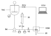
本特許の対象である、最終製品の特性を自動的に調製する塗料製造システムは、基本的に、容積式自動較正器を備えた定量射出モジュール(VDM)、少なくとも1つの連続製造モジュールで回転機構(RPT)、少なくとも1つのタンク(T)で混合ステーション(MS)・連続特性調製ステーション(CAS)・充填ステーション(FM)の間を移動させる。図1および図2に示すように、洗浄溶剤ミストを発生させるマニホールド(CM)と一体化した洗浄ステーション(CS)と、コンピュータプログラムの命令セットから定量射出モジュール(VDM)および連続処理モジュールユニットに実行させるコマンドを送信する中央制御ユニット(CCU)から構成されている。 The paint manufacturing system that is the subject of this patent, which automatically adjusts the properties of the final product, basically comprises a volumetric dosing module (VDM) with a volumetric autocalibrator, at least one continuous production module with a rotating mechanism (RPT), at least one tank (T) for moving between a mixing station (MS), a continuous property preparation station (CAS) and a filling station (FM). As shown in Figures 1 and 2, it comprises a cleaning station (CS) integrated with a manifold (CM) that generates a cleaning solvent mist, and a central control unit (CCU) that sends commands from a computer program instruction set to the volumetric dosing module (VDM) and the continuous processing module units to execute.
図3・図3Aに示すように、定量射出モジュール (VDM)は、中央制御ユニット(CCU)から受け取ったコマンドによって前記アーム(10)を移動させる空気圧アクチュエータ(12)によって駆動されるレバー機構を備えた一連のアーム(10)で構成されており、前記アーム(10)は、中央制御ユニット(CCU)で事前に規定された量の成分を投入する計量バルブ(20)が自由端にある。 As shown in Figures 3 and 3A, the VDM consists of a series of arms (10) with lever mechanisms driven by pneumatic actuators (12) that move the arms (10) according to commands received from a central control unit (CCU), and the arms (10) have metering valves (20) at their free ends that dispense the amount of ingredient predefined by the central control unit (CCU).
中央制御ユニット(CCU)は、タンク(T)内の投入対象成分に相当するアーム(10)を駆動し、続いて定量射出ポンプ(Bd)によって供給タンク(TAC)に貯蔵されている成分を流すための計量バルブ(20)を整列させる。中央制御ユニット(CCU)が定量射出バルブ(20)を再循環位置に合わせ、アーム(10)を初期位置に戻すと、規定成分の量に達するまで、連続製造方式モジュールのタンク(T)に成分を流す。 The central control unit (CCU) drives the arm (10) corresponding to the component to be added in the tank (T), and then aligns the metering valve (20) to allow the component stored in the supply tank (TAC) to flow by the constant-volume injection pump (Bd). When the central control unit (CCU) aligns the constant-volume injection valve (20) to the recirculation position and returns the arm (10) to its initial position, the component flows into the tank (T) of the continuous manufacturing module until the specified amount of the component is reached.
図3Bおよび図3Cに詳細を表示されているように、定量射出バルブ(20)は、定量射出ポンプ (Bd)によって供給タンク(TAC)に貯蔵されている成分を受け取る注入口(21)と、空気圧アクチュエータシリンダ(12)が後退している間に、定量射出ポンプ (Bd)によって移送された成分の全流量をタンク(T)に直接排出する投与ノズル(22)があり「定量射出モード」と呼ばれる。 As shown in detail in Figures 3B and 3C, the metered dose injection valve (20) has an inlet (21) that receives the components stored in the supply tank (TAC) by the metered dose pump (Bd), and a dosing nozzle (22) that directly discharges the entire flow of the components transferred by the metered dose pump (Bd) into the tank (T) while the pneumatic actuator cylinder (12) is retracted, which is called the "metered dose injection mode."
空気圧アクチュエータシリンダ (12) を前進させると、供給タンク (TAC) から受け取った成分が定量射出バルブ (20) 内で再循環し、排出口 (23) を介して供給タンク(TAC)に戻り「再循環モード」と呼ばれる。 When the pneumatic actuator cylinder (12) is advanced, the component received from the supply tank (TAC) is recirculated within the metered dose valve (20) and returned to the supply tank (TAC) through the outlet (23), which is called the "recirculation mode."
定量射出モジュール(VDM)のアーム(10)の上方に配置された画像取得ユニット(IM)は、中央制御ユニット(CCU)から受信したコマンドからこれらのアーム(10)の起動を連続的に記録し、画像のデジタル処理によって、図3に示すように、定量射出ノズルアーム(10)の位置決めとインターロック、および定量射出バルブ(20)の開閉を確認する。 The image acquisition unit (IM), located above the arms (10) of the dose delivery module (VDM), continuously records the activation of these arms (10) from commands received from the central control unit (CCU) and, by digital processing of the images, verifies the positioning and interlocking of the dose delivery nozzle arms (10) and the opening and closing of the dose delivery valves (20), as shown in Figure 3.
図4および図4Aに示すように、定量射出モジュール(VDM)に供給する定量射出ポンプ(Bd)は、1台の電動機(M)によって駆動される2本の共有中心軸(14a)・(14b)に設置され、同じ速度で回転し、第2の軸(14b)は、遊星歯車減速機(131)と、第1の軸(14a)から第2の軸(14b)への力の伝達に加えて、その回転方向を反転させるスプロケットとローラチェーンのセットによって、第1の軸(14a)に結合され、同期しており、この第2の軸 (14b) に沿って設置された一連の定量射出ポンプ(Bd)の回転方向に適合させている。 As shown in Figures 4 and 4A, the constant-volume injection pumps (Bd) supplying the constant-volume injection module (VDM) are mounted on two shared central shafts (14a) and (14b) driven by one electric motor (M) and rotate at the same speed, and the second shaft (14b) is coupled to the first shaft (14a) by a planetary gear reducer (131) and a set of sprockets and roller chains that transmit power from the first shaft (14a) to the second shaft (14b) as well as reverse its direction of rotation, and is synchronized with the direction of rotation of the series of constant-volume injection pumps (Bd) mounted along this second shaft (14b).
各定量射出ポンプ(Bd)には、図4Cに示すように、空気圧アクチュエータ(132)によって空気圧で駆動されるギアセットが設けられており、後述する駆動機構によって、各定量射出ポンプ(Bd)をそれぞれの共有中心軸(14a)・(14b)に結合または分離することができるようになっている。各定量射出ポンプ(Bd)への動力伝達は、ローラーチェーンとスプロケット(130)によって行われる。2本の共有中心軸 (14a)・(14b)は、第1共有中心軸(14a)の一端に電気モーター(M)をその反対側には変速機(133)を介して結合している。共有中心軸(14b)の先端には、図4Bに示すように、軸(14a)・(14b)の回転数をカウントするデジタルエンコーダ(134)が設置されており、このデータを中央制御ユニット(CCU)に送る。 As shown in FIG. 4C, each of the constant-volume injection pumps (Bd) is provided with a gear set pneumatically driven by a pneumatic actuator (132), and each of the constant-volume injection pumps (Bd) can be connected or disconnected to the respective shared central shafts (14a) and (14b) by a drive mechanism described later. Power is transmitted to each of the constant-volume injection pumps (Bd) by a roller chain and sprockets (130). The two shared central shafts (14a) and (14b) are connected to an electric motor (M) at one end of the first shared central shaft (14a) and to the other end via a transmission (133). At the tip of the shared central shaft (14b), as shown in FIG. 4B, a digital encoder (134) is installed to count the number of rotations of the shafts (14a) and (14b), and this data is sent to the central control unit (CCU).
図4Dに詳述されているように、定量射出ポンプ(Bd)を共有駆動軸(14a)・(14b)に結合するか否かの機能を有する個々の定量射出ポンプ駆動機構である。例えば、定量射出ポンプ (Bd1・Bd13・Bd21・Bd70) に対応する成分を射出する必要がある場合、個別定量射出ポンプ駆動部は、これらのポンプ(Bd1・Bd13・Bd21・Bd70)のみを共有軸(14a)・(14b)に結合し、その他の定量射出ポンプ(Bd)は静止した状態にすることができる。この状態で、空気圧アクチュエータ(132)を作動させると、ポンプギア機構連結(135)の駆動アームが作動し、ポンプギア機構の送り支持具(136)が駆動される。そして、この支持具(136)は、定量射出ポンプ連結デバイス(137)を前方に押し出し、オス溝が定量射出ポンプ(Bd)のメス型カップリングデバイス(13)のメス溝と嵌合し、このようにして2つのデバイス(137)と(13)が結合する。定量射出ポンプ連結デバイス(137)は、共有中心軸(14a)・(14b)に依存しているので、これにより軸(14a)・(14b)の回転駆動が最終的に定量射出ポンプ(Bd)に伝わる。 As shown in FIG. 4D, each of the individual metered injection pump drive mechanisms has the function of whether or not to couple the metered injection pumps (Bd) to the shared drive shafts (14a) and (14b). For example, when it is necessary to inject components corresponding to the metered injection pumps (Bd1, Bd13, Bd21, and Bd70), the individual metered injection pump drive unit can couple only these pumps (Bd1, Bd13, Bd21, and Bd70) to the shared shafts (14a) and (14b), and the other metered injection pumps (Bd) can be stationary. In this state, when the pneumatic actuator (132) is operated, the drive arm of the pump gear mechanism connection (135) is operated, and the feed support (136) of the pump gear mechanism is driven. The support (136) then pushes the constant-volume injection pump coupling device (137) forward, and its male groove fits into the female groove of the female coupling device (13) of the constant-volume injection pump (Bd), thus connecting the two devices (137) and (13). The constant-volume injection pump coupling device (137) depends on the shared central shafts (14a) and (14b), so that the rotational drive of the shafts (14a) and (14b) is ultimately transmitted to the constant-volume injection pump (Bd).
空気圧アクチュエータ (132)が後退位置のときは、駆動共有中心軸(14a)・(14b)と定量射出ポンプ(Bd)との間に結合がなかったので、定量射出ポンプ連結デバイス(137)とメス型カップリングデバイス(13)との嵌合は起こらず、それに対応する定量射出ポンプ(Bd)は静止の状態である。 When the pneumatic actuator (132) is in the retracted position, there is no connection between the drive shared central shafts (14a) and (14b) and the constant-volume injection pump (Bd), so the constant-volume injection pump connecting device (137) does not engage with the female coupling device (13), and the corresponding constant-volume injection pump (Bd) is stationary.
定量射出ポンプ(Bd)は、図5の模式図に示すように定量注入式シリンジ型較正ユニット(30)によって自動的に較正される。 The metered dose injection pump (Bd) is automatically calibrated by a metered dose syringe-type calibration unit (30) as shown in the schematic diagram of Figure 5.
この図には、定量注入式シリンジ型較正ユニット(30)のほかに、方向制御弁(V1)(V2)・成分供給タンク(TAC)・定量射出ポンプ(Bd)・タンクレベルトランスミッタ(LT)・射出/再循環ライン圧力トランスミッター(PT)・製品温度トランスミッター(TT)・自走式圧力調整弁(PCV)・定量射出バルブ(20)など、定量投入システムで使用されるすべての構成要素が示されている。 The diagram shows all the components used in a dosing system, including the dosing syringe-type calibration unit (30), directional control valves (V1) (V2), ingredient supply tank (TAC), dosing pump (Bd), tank level transmitter (LT), injection/recirculation line pressure transmitter (PT), product temperature transmitter (TT), self-propelled pressure regulating valve (PCV), and dosing valve (20).
この較正ユニットは、定量注入式シリンジ型較正ユニット(30)の内部を保護する円筒金属(38)と、後述する2つの磁気位置センサーを付属している。また、較正ユニット(30)の外側には電気配線ボックス(37)があり、ピストンガイド軸(36)が見えている。較正ユニット(30)の下端には、定量射出ポンプ(Bd)の射出ラインに接続するための接続口(301)が設けられている。較正ユニット(30)の内部には、定量注入式シリンジ型較正ユニット(30)の筒として機能する非磁性円筒金属(39)が使われており、ここに2つの磁気位置センサ(34a)・(34b)が固定されている。この円筒金属(39)の内部には、シールガスケット(32)を備えたピストン(31)が装備されており、前記ガスケット(32)の間には、図6Aおよび図6Bに示すように、シリンジャー(39)の本体の凹んだ部分に磁気位置センサー(34a)および(34b)を感知する磁石(33)が設置されている。 This calibration unit comes with a cylindrical metal (38) that protects the inside of the fixed-volume syringe-type calibration unit (30), and two magnetic position sensors, which will be described later. In addition, an electrical wiring box (37) is located on the outside of the calibration unit (30), and the piston guide shaft (36) is visible. At the bottom end of the calibration unit (30), a connection port (301) is provided for connecting to the injection line of the fixed-volume injection pump (Bd). Inside the calibration unit (30), a non-magnetic cylindrical metal (39) is used that functions as the cylinder of the fixed-volume syringe-type calibration unit (30), and two magnetic position sensors (34a) and (34b) are fixed to it. Inside this cylindrical metal (39) is a piston (31) equipped with a seal gasket (32), and between the gaskets (32) are magnets (33) that sense magnetic position sensors (34a) and (34b) in a recessed portion of the body of the syringe (39), as shown in Figures 6A and 6B.
第1磁気位置センサー(34a)は、定量射出ポンプ(Bd)のピストン射出ラインに接続された定量注入式シリンジ型較正ユニット(30)の接続口(301)の近傍に設置され、他方の磁気位置センサ(34b)は、接続口(301)と反対側の端部近傍に設置される。較正ユニット(30)において、ピストンロッド側(31)に圧縮空気入口(35)があり、投入工程において定量射出ポンプが直面する圧力に対抗するためで、ピストンロッド側の圧縮空気によって接続口(301)完全に押されて、較正の信頼性を高めている。 The first magnetic position sensor (34a) is installed near the connection port (301) of the constant-volume syringe-type calibration unit (30) connected to the piston injection line of the constant-volume injection pump (Bd), and the other magnetic position sensor (34b) is installed near the end opposite the connection port (301). The calibration unit (30) has a compressed air inlet (35) on the piston rod side (31) to counter the pressure the constant-volume injection pump faces during the dosing process. The connection port (301) is completely pressed by the compressed air on the piston rod side, improving the reliability of the calibration.
定量注入式シリンジ型較正ユニット(30)の本体に設置された磁気位置センサー(34a)と他の磁気位置センサー(34b)との間の移動容積の計算は、式1で定義される。 The calculation of the volume of movement between the magnetic position sensor (34a) installed on the body of the constant-volume syringe-type calibration unit (30) and the other magnetic position sensor (34b) is defined by Equation 1.
式1:Vcal = n R2 x L,
ここで、
Vcal = 構成ユニットの容積(30) [ml]
R = 較正シリンジ容器の半径 [cm]
L = 2つの磁気センサー(34a) ・(34b)の間の距離 [cm]
Formula 1: Vcal = n R2 x L,
Where:
Vcal = Volume of component unit(30) [ml]
R = radius of the calibration syringe container [cm]
L = distance between the two magnetic sensors (34a) and (34b) [cm]
定量射出ポンプ(Bd)を較正するには、図5に示す模式図に基づいて、中央制御ユニット(CCU)が開放バルブ(V1)と閉塞バルブ(V2)を指令する。これらのバルブ(V1)・(V2)の位置が確認されると、較正中の定量射出ポンプ(Bd)は一定の基準回転速度で駆動され、その速度と回転数はコントロールセンター(CCU)によって監視される。直ちに、圧力流体は定量射出ポンプ(Bd)の機械的作用により定量注入較正ユニット(30)に流入し始め、ピストン(31)が後方に移動する。磁石(33)が第1磁気位置センサ(34a)の位置に来た瞬間、中央制御ユニット(CCU)は、定量射出ポンプ(Bd)の軸と結合したエンコーダ(134)によって、定量射出ポンプ(Bd)の軸の回転数をカウンタする。そして、ピストン(31)の移動が第2磁気センサー(34b)で停止し、中央制御ユニット(CCU)が監視する回転数カウンターで定量射出ポンプ(Bd)が直ちに停止する。その後、閉塞バルブ(V2)が開かれ、ピストン(31)の後面にかかる圧縮空気の圧力によってピストン(31)が自動的に逆方向に進み、定量注入較正ユニット(30)を空にする。中央制御ユニット(CCU)は、磁石(33)の移動によって第1磁気センサー(34a)の監視を通じて定量注入較正ユニット(30)が空になったことを示す。この間、開放バルブ(V1)は閉塞している。中央制御ユニット(CCU)は、2つのセンサー(34a)・(34b)の間の移動によって定量ポンプ(Bd)軸の回転数を、式2を使って移動容量を算出する。 To calibrate the constant-volume injection pump (Bd), the central control unit (CCU) commands the open valve (V1) and the close valve (V2) based on the schematic diagram shown in FIG. 5. Once the positions of these valves (V1) and (V2) are confirmed, the constant-volume injection pump (Bd) being calibrated is driven at a constant reference rotation speed, and its speed and number of rotations are monitored by the control center (CCU). Immediately, the pressurized fluid starts to flow into the constant-volume injection calibration unit (30) due to the mechanical action of the constant-volume injection pump (Bd), and the piston (31) moves backward. At the moment when the magnet (33) comes to the position of the first magnetic position sensor (34a), the central control unit (CCU) counts the number of rotations of the shaft of the constant-volume injection pump (Bd) by the encoder (134) coupled to the shaft of the constant-volume injection pump (Bd). Then, the movement of the piston (31) is stopped by the second magnetic sensor (34b), and the constant-volume injection pump (Bd) is immediately stopped by the revolution counter monitored by the central control unit (CCU). The closing valve (V2) is then opened, and the piston (31) automatically moves in the reverse direction due to the compressed air pressure on the rear surface of the piston (31), emptying the constant-volume injection calibration unit (30). The central control unit (CCU) indicates that the constant-volume injection calibration unit (30) is empty by monitoring the first magnetic sensor (34a) by the movement of the magnet (33). During this time, the opening valve (V1) is closed. The central control unit (CCU) calculates the number of revolutions of the metering pump (Bd) shaft by the movement between the two sensors (34a) and (34b), and the movement volume using Equation 2.
式2:Vdb = Vcal/N,
ここで、
Vdb = 回転数対移動容量 [ml/回転数]
Vcal =定量注入較正ユニット(30) の内部容量[ml]
N =較正工程中に定量射出ポンプ(Bd)が行った回転数。
Equation 2: Vdb = Vcal/N,
Where:
Vdb = Revolutions per minute vs. volume moved [ml/revs]
Vcal = internal volume of the dosing calibration unit (30) [ml]
N = number of revolutions made by the metering pump (Bd) during the calibration step.
式2で得られたデータをもとに、中央制御ユニット(CCU)は、システム内の各定量射出ポンプ(Bd)の個々のポンプ排出量を記載したデータベースを更新する。 Based on the data obtained from Equation 2, the central control unit (CCU) updates a database containing the individual pump displacements of each metering pump (Bd) in the system.
連続製造方式モジュールでは、図8に示すように、回転機構(RPT)は、中央制御ユニット(CCU)によって駆動されるインデックスユニットを備えており、 起動後、個々の減速機付きモーター(Mr)によって回転軸(40)が回転する。ラジアルアーム(401)が回転軸(40)を介して動作することで、少なくとも1つのタンク(T)が、混合ステーション(MS)、連続特性調製ステーション(CAS)、洗浄ステーション(CS)、定量射出モジュール(VDM)と順次移動し、中央制御ユニット(CCU)であらかじめマニュアルと一致した方法に従って、成分がタンク(T)の内部に投入される。 In the continuous manufacturing module, as shown in FIG. 8, the rotating mechanism (RPT) is equipped with an indexing unit driven by the central control unit (CCU), and after starting, the rotating shaft (40) is rotated by the individual motors (Mr) with reducers. The radial arm (401) operates via the rotating shaft (40), and at least one tank (T) moves sequentially through the mixing station (MS), the continuous property preparation station (CAS), the cleaning station (CS), and the fixed-volume injection module (VDM), and the components are added to the tank (T) according to a method previously set in accordance with the manual in the central control unit (CCU).
回転機構(RPT)は、減速機付きモーター(Mr)によって回転するラジアルアーム(401)が取り付けられた中心軸(40)を有し、ラジアルアーム(401)の自由端には、定量射出モジュール(VDM)によって成分が投入されるタンク(T)が配置されている。 The rotation mechanism (RPT) has a central shaft (40) to which a radial arm (401) is attached, which is rotated by a motor (Mr) with a reducer. At the free end of the radial arm (401) is a tank (T) into which components are dispensed by a fixed-volume dosing module (VDM).
図8Aおよび図8Bに示すように、タンク(T)には、投入された成分が受け取られ、定量射出バルブ(20)によって投入される上部開口部を有している。タンク(T)の内部空洞には、タンク(T)の内部構造には固定された軸受けを備えた羽根車軸 (41) が配置されており、この羽根車軸(41)には、傾斜パドル型などの撹拌機(411)装備が想定されている。タンク(T)の円錐形の底面には、排出弁(42)が配置されている。 As shown in Figures 8A and 8B, the tank (T) has an upper opening through which the charged components are received and discharged by a metered dose valve (20). In the internal cavity of the tank (T), an impeller shaft (41) having a bearing fixed to the internal structure of the tank (T) is disposed, and this impeller shaft (41) is assumed to be equipped with an agitator (411), such as an inclined paddle type. A discharge valve (42) is disposed on the conical bottom of the tank (T).
連続製造方式モジュールの混合ステーション(MS)は、連続製造方式モジュール(CAS)での調製/充填工程の開始前に、タンクの内容物(T)を事前に均質化する。 The mixing station (MS) in the continuous manufacturing module pre-homogenizes the tank contents (T) before the preparation/filling process begins in the continuous manufacturing module (CAS).
この混合ステーション(MS)は、図9に示すように、混合段階で材料の飛散や蒸発を防ぐために、モーター(M2)とタンクシーリングカバー(51)を備えた空気圧式昇降機構(50)が、タンク(T)の上部に位置するように配置されている。 As shown in Figure 9, this mixing station (MS) is arranged so that a pneumatic lifting mechanism (50) equipped with a motor (M2) and a tank sealing cover (51) is located at the top of the tank (T) to prevent the material from scattering or evaporating during the mixing stage.
タンク(T)がモータ(M2)の下方に位置した瞬間、回転機構(RPT)の動きにより、空気圧式昇降機構(50)が自動的にタンクシーリングカバー(51)を下降させ、前記タンク(T)の上部開口部に結合させる。電動機(M2)のシャフトに固定されたトラクションピン(52)は、図9Aに明らかなように、攪拌機(411)によってタンク(T)の内容物の混合を行うために、前記電動機(M2)を均質化羽根車軸(41)に結合する。 At the moment when the tank (T) is located under the motor (M2), the movement of the rotation mechanism (RPT) automatically causes the pneumatic lifting mechanism (50) to lower the tank sealing cover (51) and connect it to the upper opening of the tank (T). A traction pin (52) fixed to the shaft of the motor (M2) connects the motor (M2) to the homogenizing impeller shaft (41) for mixing the contents of the tank (T) by the agitator (411), as can be seen in FIG. 9A.
均質化ステップの後、定量射出モジュール(VDM)で投入され、混合ステーション(MS)で予備均質化されたタンク(T)は、回転機構(RPT)によって回転し、塗料ロットの特性を「インライン」で分析・修正する機能を持つ連続特性調製ステーション(CAS)に送られる。 After the homogenization step, the tank (T), which has been fed by the Volumetric Dosing Module (VDM) and pre-homogenized in the Mixing Station (MS), is rotated by the Rotating Mechanism (RPT) and sent to the Continuous Properties Preparation Station (CAS), which has the ability to analyze and modify the properties of the paint lot "in-line".
連続特性調製ステーション(CAS)は、混合ステーション(MS)と同様に、図9および図9Aに示されているように、モーター(M2)を備えた空気圧式昇降機構(50)と、タンク(T)の上部に位置するためのタンクシーリングカバー(51)を装備している。 The continuous property preparation station (CAS), like the mixing station (MS), is equipped with a pneumatic lifting mechanism (50) with a motor (M2) and a tank sealing cover (51) for positioning on top of the tank (T), as shown in Figures 9 and 9A.
タンク(T)がモータ(M2)の下方に置かれると、回転機構(RPT)の動作により、空気圧式昇降機構(50)が自動的にタンクシーリングカバー(51)を下降させ、前記タンク(T)の上部開口部に結合させる。電動機(M2)の軸に固定されたトラクションピン(52)が、前記電動機(M2)と均質化羽根車シャフト(41)と連結している。同時に、タンク(T)の排出弁(42)自動結合装置(421)によって材料調製循環ポンプ(mb1)に連結する。
そのあとすぐ、タンク攪拌機のモーター(T)は材料調製循環ポンプ(mb1)と同時に中央制御ユニット(CCU)で設定された循環流量に達するまで動作する。流量に達すると、中央制御ユニット(CCU)は、多機能特性用測定器(80)と湿式色測定モジュール(100)を使って分析データの収集を開始する。材料調製循環ポンプ(mb1)で設定された材料の流量に基づいて得られたデータから、中央制御ユニット(CCU)は、連続式ラインミキサー(60)で連続的に投入される必要のある各成分の個別調製量を計算する。この調整量は、各調製成分射出ポンプ(Bda)の異なる回転数に対して補正をする必要がある。この情報をもとに、中央制御ユニット(CCU)は調整部品の調製成分射出ポンプ (Bda)の回転数を調整し、同時に連続式ラインミキサー(60)の三方弁(vt)を作動させる。まさにその瞬間、材料調製循環ポンプ(mb1)から来る、連続式ラインミキサー(60)を通過する調整中の材料の流れは、連続的な条件で混合室(601)内の三方弁(vt)から来る調整成分の分担の流れを、射出弁(61)を通して受け、この混合物は連続式ラインミキサー(60)の均質化羽根車(17)によって激しく混合される。
When the tank (T) is placed under the motor (M2), the pneumatic lifting mechanism (50) automatically lowers the tank sealing cover (51) through the operation of the rotation mechanism (RPT) and connects it to the upper opening of the tank (T). The traction pin (52) fixed to the shaft of the motor (M2) connects the motor (M2) to the homogenizing impeller shaft (41). At the same time, the discharge valve (42) of the tank (T) is connected to the material preparation circulation pump (mb1) through the automatic connection device (421).
Immediately afterwards, the motor (T) of the tank agitator runs simultaneously with the material preparation circulation pump (mb1) until the circulation flow rate set by the central control unit (CCU) is reached. Once this flow rate is reached, the central control unit (CCU) starts to collect analytical data using the multifunctional property measuring device (80) and the wet color measuring module (100). From the data obtained based on the material flow rate set by the material preparation circulation pump (mb1), the central control unit (CCU) calculates the individual preparation amounts of each component that need to be continuously dosed in the continuous line mixer (60). This adjustment amount needs to be corrected for the different speeds of the individual preparation component injection pumps (Bda). Based on this information, the central control unit (CCU) adjusts the speed of the adjustment component preparation injection pumps (Bda) and simultaneously activates the three-way valve (vt) of the continuous line mixer (60). At that very moment, the flow of material being conditioned coming from the material conditioning circulation pump (MB1) passing through the continuous line mixer (60) receives in continuous condition a share of the flow of conditioning components coming from the three-way valve (VT) in the mixing chamber (601) through the injection valve (61), and this mixture is vigorously mixed by the homogenizing impeller (17) of the continuous line mixer (60).
図10に示すように、中央制御ユニット(CCU)によるデータ収集のために、連続特性調製ステーション(CAS)には、連続式ラインミキサー(60)と、コリオリ力利用の質量流量・温度・粘度・密度等の多機能特性用測定器(80)が設置されている。湿式色測定ユニット(100)、調製中の材料を順方向または循環タンクに戻すためまたは製品が既定の仕様に達したとき充填機の方向に流すための三方弁を備えている。そしてタンク(T)用の均質化ユニットがある。 As shown in Figure 10, the Continuous Properties Preparation Station (CAS) is equipped with a continuous line mixer (60), a Coriolis force mass flow, temperature, viscosity, density, etc. multi-function property measuring device (80) for data collection by the Central Control Unit (CCU), a wet color measuring unit (100), a three-way valve to allow the material being prepared to flow forward or back to the circulation tank or to the filler when the product reaches the pre-defined specifications, and a homogenization unit for the tank (T).
図10および図10Aに示すように、連続特性調製ステーション(CAS)には、製造中の塗料の特性を調製するための連続式ラインミキサー(60)が設置されている。前記連続式ラインミキサー(60)は、製造中の塗料のロットの特性を調製するための成分の連続的な流れを供給し、材料調製循環ポンプ(mb1)によってタンク(T)の内容物を連続特性調製ステーション(CAS)に再循環させる調製中の製品の流れに、スピード感のある成分の効率的な混合を同時に行う。 As shown in Figures 10 and 10A, the continuous property preparation station (CAS) is equipped with a continuous line mixer (60) for preparing the properties of the paint lot being produced. The continuous line mixer (60) provides a continuous flow of ingredients for preparing the properties of the paint lot being produced, and simultaneously provides fast and efficient mixing of the ingredients into the product stream being prepared which is recirculated by the material preparation circulation pump (mb1) to the continuous property preparation station (CAS).
電動機(M3)によって駆動される連続ラインミキサー(60)は、図10Bおよび図10Cに示すように、デッドボリュームが少なく応答時間が短い混合室(601)を備えた本体に、均質化羽根車(17)と、混合室(601)を一体的に冷却するための外部容器(602)が設けられている。前記連続ラインミキサー(60)は、混合室(601)に設置されたラジアル射出弁(61)を通して、製造中の塗料のロットの特性を調製するための成分の連続的な流れを供給する。図10および図10Aに示されるように、着色剤定量射出ポンプ(Bda)は同時に高速混合かつ効率的な材料の流れを連続特性調製ステーション(CAS)に色調製用着色剤を供給する。タンク(T)から送られてきた製品の流れを調製し、材料調製循環ポンプ(mb1)によって混合機内部に戻す。 As shown in Figures 10B and 10C, the continuous line mixer (60) driven by the electric motor (M3) is provided with a mixing chamber (601) with a small dead volume and a short response time, a homogenizing impeller (17), and an external container (602) for integrally cooling the mixing chamber (601). The continuous line mixer (60) supplies a continuous flow of components for adjusting the properties of the paint lot being produced through radial injection valves (61) installed in the mixing chamber (601). As shown in Figures 10 and 10A, the colorant metering injection pump (Bda) simultaneously supplies a high-speed and efficient material flow of colorants for color adjustment to the continuous property adjustment station (CAS). The product flow sent from the tank (T) is adjusted and returned to the inside of the mixer by the material preparation circulation pump (mb1).
混合室(601)の底部には、空気圧で作動する排出弁が設置されており、連続式ラインミキサー(60)の内部窪みの洗浄・除染プロセスの際に使用される。 At the bottom of the mixing chamber (601) is a pneumatically operated drain valve, which is used during the cleaning and decontamination process of the internal cavity of the continuous line mixer (60).
連続式ラインミキサー(60)には、コリオリ技術を用いた多機能特性用測定器(粘度・密度・質量流量)(80)と湿式色測定モジュール(100)が組み込まれており、これらの特性を測定したデータを中央制御ユニット(CCU)に送り、そこでコンピュータプログラムが製品仕様を達成するための調製を計算する。この調製は、ラジアル射出弁(61)を通して連続式ラインミキサー(60)の混合室(601)内に投与される成分の連続的な流れの変化に解釈される。 The continuous line mixer (60) incorporates a multi-function property measuring instrument (viscosity, density, mass flow) (80) using Coriolis technology and a wet color measuring module (100) that transmits the measured data of these properties to a central control unit (CCU) where a computer program calculates the formulation to achieve the product specifications. This formulation translates into a continuous flow change of the components dosed into the mixing chamber (601) of the continuous line mixer (60) through the radial injection valves (61).
図10Dに示すように、多機能特性用測定器(80)の後方に三方弁(vt)が設置されいて、この測定器がまだ適合していない材料を単管パイプ(t1)を通してタンク(T)に戻すように指令し、製品が中央制御ユニット(CCU)で規定された最終仕様に達するまでこの状態を維持し、製品が最終仕様に達したとき、前記三方弁(vt)が製品を充填モジュール(FM)に送る指令をする。 As shown in FIG. 10D, a three-way valve (vt) is installed behind the multi-function characteristic measuring device (80), which commands the material that is not yet in compliance to return to the tank (T) through the single pipe (t1) and maintains this state until the product reaches the final specification defined by the central control unit (CCU), at which point the three-way valve (vt) commands the product to be sent to the filling module (FM).
図10E・図10Fに示すように、ラジアル射出弁(61)は、導入口(71)を通して着色剤定量射出ポンプ(Bda)から成分を受け取り、前記材料は、連続式ラインミキサーの混合室(601)に結合された閉塞プラグ(72)を通して射出されるまでラジアル射出弁(61)の内部を移動する。閉塞プラグ(72)はバルブシャフト(73)に固定されており、閉塞プラグ(72)とバルブシートの間で漏れなくするために、円錐ばね(74)によって張力がかけられている。ラジアル射出弁(61)によって投入される調製材料は、着色剤定量射出ポンプ(Bda)の油圧力の抵抗を克服しなければならない。バルブシャフト(73)の後部にはフォーク形状のシャフトロック(77)があり、工程ストップの時ラジアル射出弁(61)の締め付けを保証する機能を備えている。前記シャフトロック(77)は空気圧スライド機構(75)に固定されており、投入工程中にバルブシャフト(73)を解放したいときには、エアー接続(76)に圧縮空気を入れてエアーチャンバー機構(75)のチャンバーを加圧する必要がある。 As shown in Figures 10E and 10F, the radial injection valve (61) receives the ingredients from the colorant metering pump (Bda) through the inlet (71), and the materials move inside the radial injection valve (61) until they are injected through the blocking plug (72) connected to the mixing chamber (601) of the continuous line mixer. The blocking plug (72) is fixed to the valve shaft (73) and tensioned by a conical spring (74) to prevent leakage between the blocking plug (72) and the valve seat. The preparation material injected by the radial injection valve (61) must overcome the resistance of the hydraulic force of the colorant metering pump (Bda). At the rear of the valve shaft (73) there is a fork-shaped shaft lock (77) which has the function of ensuring the clamping of the radial injection valve (61) when the process is stopped. The shaft lock (77) is fixed to the pneumatic slide mechanism (75), and when you want to release the valve shaft (73) during the insertion process, you need to feed compressed air into the air connection (76) to pressurize the chamber of the air chamber mechanism (75).
回転式タンク(T)から出てくる調製中の製品の温度調整のために、円筒面に切削加工された単一の螺旋状の長方形の溝に比較的薄いフィルムがある熱交換器(90)が設けられている。このようにして、この流路を流れる材料は、高粘度であっても極めて効率的に熱交換を行います。これは、主に伝導機構による熱伝導が促進されるためで、塗料やその関連品などの低粘度~中高粘度の材料では、対流による熱伝達は層流となり流体の流れの仕組みによって非常に損なわれる。 To regulate the temperature of the product being prepared coming out of the rotating tank (T), a heat exchanger (90) is provided with a relatively thin film in a single spiral rectangular groove cut into the cylindrical surface. In this way, the material flowing through this channel exchanges heat very efficiently even at high viscosity. This is mainly because heat transfer is promoted by the conduction mechanism; for low to medium-high viscosity materials such as paints and related products, convection heat transfer is highly impaired by the laminar flow and fluid flow mechanisms.
図11、図11A・図11Bに示すように、熱交換器(90)は、材料が流れる螺旋状の長方形の溝が表面に加工された円筒面を有している。同心円状の内筒(91)と外筒(92)に囲まれ、前記内筒(91)と外筒(92)の間には、熱交換器ミラーに設置された流入口(93)から入った冷媒が、最初に内筒(91)の螺旋状の流路を通過して循環する。熱交換器ミラーに到達するまでの間、冷却水の流れは外筒(92)の螺旋状の流路に導かれ、そこから冷却水は熱交換器の外部ハウジング(901)を通って、再び熱交換器ミラー(94)に戻る。この経路は、温度調整中の製品が熱交換器(90)を通過する中間シリンダー(95)に対して完全に密閉されている。温度調整中の製品は、熱交換器ミラー(94)の流入口(941)から入り、熱交換器バックミラー(943)に設置された製品排出口(942)から熱交換器を出るようになっている。 As shown in Figures 11, 11A and 11B, the heat exchanger (90) has a cylindrical surface with a spiral rectangular groove on its surface through which the material flows. It is surrounded by a concentric inner cylinder (91) and an outer cylinder (92), between which the coolant enters through an inlet (93) installed in the heat exchanger mirror and circulates, first passing through the spiral passage of the inner cylinder (91). On its way to the heat exchanger mirror, the flow of cooling water is directed through the spiral passage of the outer cylinder (92), from where it passes through the outer housing (901) of the heat exchanger and returns to the heat exchanger mirror (94). This path is completely sealed with respect to the intermediate cylinder (95) through which the product being temperature-conditioned passes through the heat exchanger (90). The product undergoing temperature adjustment enters the heat exchanger mirror (94) through an inlet (941) and exits the heat exchanger through a product outlet (942) located on the heat exchanger rearview mirror (943).
図12に示すように、制御やインターロックのためのコンピュータ・コントローラ・ユニットを備えたロボットデバイス(DR)は、光ファイバーによるデジタル通信で中央制御ユニット(CCU)と相互に接続されている。前記ロボットデバイス(DR)は、"自然のまま "の特性(液体ベース)を持つ塗料や関連製品の色具合を正確に測定するために設計された(液体媒体中)湿式色測定セル(101)を介して、オンラインで湿式色を測定・調整する。 As shown in Figure 12, the robotic device (DR) with a computer controller unit for control and interlocking is interconnected with the central control unit (CCU) through digital communication over optical fiber. The robotic device (DR) measures and adjusts the wet color online through a wet color measuring cell (101) (in liquid medium) designed for accurate measurement of the color of paints and related products with "natural" properties (liquid-based).
図12A・図12Bに示すように、湿式色測定セル(101)(液体状) は、そこを流れる製品のために気密性の高い容器である。前記セル(101)を流れる材料は、入口ポート(125a)から連続した流れで出口ポート(125b)を通してセルから出る。セルには透明な水晶光学窓(102)があり、セルの外側に取り付けられた分光光度計(103)によって、可視スペクトル領域(400~700nm)の湿潤環境で色調を測定することができる。全ての測定・洗浄周期は分光光度計(103)で測定されたパラメータに基づいて中央制御ユニット(CCU)によって定量射出ポンプ(Bda)で色調を調製する。タンク(T)の内容物がすべて処理されるまで、仕様内にした材料を充填装置に供給する。 As shown in Figures 12A and 12B, the wet color measuring cell (101) (liquid state) is an airtight container for the product flowing therethrough. The material flowing through said cell (101) is a continuous flow from the inlet port (125a) and exits the cell through the outlet port (125b). The cell has a transparent quartz optical window (102) that allows the color to be measured in a wet environment in the visible spectral range (400-700 nm) by a spectrophotometer (103) attached to the outside of the cell. All measurement and cleaning cycles are controlled by the central control unit (CCU) using a metering pump (Bda) to adjust the color based on the parameters measured by the spectrophotometer (103). The filling device is fed with material that is within specifications until the entire contents of the tank (T) are processed.
湿式色測定セル (液体状の)(101)は、5 barの圧力まで動作可能であるが、圧力がこの限界を超えた場合、湿式色測定セル(101)の内圧を緩和し、瞬時にこのセル(101)を減圧することで、この値よりも高い圧力から保護する安全装置(120)を備えている。この過圧防止安全デバイス(120)は、図13に示すように、測色セル(101)との接続ニップル(122)の近くに圧力トランスミッター(121)が設置されている。このトランスミッター(121)は、加圧に関してセル(101)が直面するすべての状況をリアルタイムで監視・記録し、そのデータを中央制御ユニット(CCU)に送信して、追加の安全インターロックを備えた色測定セル(101)の圧力履歴を保存することを目的としている。システムの機械的な面の安全性の観点から、透明な水晶光学窓(102)の破裂を避けるためで、この安全装置(120)は、リリーフバルブとして機能し、較正済みバネ(123)によってパイロット弁によって開閉されるシートとブロック(125)を有し、内圧が最大限度(ここでは5 bar)を超えたときに湿式色測定セル(101)の内圧を排出口(124)に逃がすためのものである。圧力が上限を超えた場合、自動的に油圧変位によりブロック(125)が後退し、その結果、色測定セル(101)が減圧され、色測定セル(101)内を循環していた材料は、排出口(124)に接続された特別な減圧ラインに排出される。 The wet color measuring cell (101) can operate up to a pressure of 5 bar, but is equipped with a safety device (120) that protects against pressures higher than this value by relieving the internal pressure of the wet color measuring cell (101) and instantly depressurizing the cell (101) if the pressure exceeds this limit. This overpressure prevention safety device (120) is a pressure transmitter (121) installed near the connecting nipple (122) with the color measuring cell (101), as shown in Figure 13. This transmitter (121) is intended to monitor and record in real time all the situations faced by the cell (101) in terms of pressurization and transmit the data to a central control unit (CCU) to store the pressure history of the color measuring cell (101) with additional safety interlocks. From the viewpoint of the mechanical safety of the system, in order to avoid the rupture of the transparent quartz optical window (102), the safety device (120) acts as a relief valve and has a seat and a block (125) that is opened and closed by a pilot valve by a calibrated spring (123) to release the internal pressure of the wet color measuring cell (101) to the outlet (124) when the internal pressure exceeds a maximum limit (here 5 bar). If the pressure exceeds the upper limit, the block (125) automatically retreats by hydraulic displacement, as a result of which the color measuring cell (101) is depressurized and the material circulating in the color measuring cell (101) is discharged into a special depressurization line connected to the outlet (124).
図14に示すように光学測定窓(102)を清掃するために、光学窓(102)の表面に凝集している可能性のある物質を、掻き取りによって機械的に除去することを促進するセルフクリーニング機能(110)が設けられている。基本的には、耐薬品性の高いエラストマー材料で作られた一連の羽根で、読み取りサイクルごとに光学式読み取り窓の内面を擦る。 To clean the optical measurement window (102), as shown in FIG. 14, a self-cleaning feature (110) is provided that facilitates mechanical removal, by scraping, of any material that may have accumulated on the surface of the optical window (102). Essentially, a series of vanes made of a highly chemically resistant elastomeric material scrape the inner surface of the optical reading window after each reading cycle.
セルフクリーニング機構(110)は、台形型に凸部(111)を備えており、荷重損失に関連する抵抗を起こすことなく、塗料の取り除きに十分な面積を見込んでいて、台形型に凸部(111)には、あらゆる種類の有機溶媒に対して高い耐薬品性を有する材料であるパーフルオロエラストマーブレード(112)がはめ込みされている。前記セルフクリーニング機構(110)は光学窓(102)に接触している。図12Bに示すように、セルフクリーニング機構(110)は、円錐形バネ(113)によって、測定用セル(102)の内側の面を押し付けている。この同一平面上で、ブレード(112)は、透明な水晶光学窓(102)の表面に接触している。この反力の結果、ブレード(112)はこの表面に押し付けられ、回転しながら、空気圧ロータリーアクチュエータ(115)の作用により、透明な水晶光学窓(102)の表面を擦り、堆積される場合の残渣を除去するとともに、光学窓(102)の表面で色読み取りセル(101)内部を循環する物質を更新することになる。 The self-cleaning mechanism (110) has a trapezoidal projection (111) that allows for a sufficient area for the removal of the paint without resistance related to load loss, and is fitted with a perfluoroelastomer blade (112), a material that has high chemical resistance to all types of organic solvents. The self-cleaning mechanism (110) is in contact with the optical window (102). As shown in FIG. 12B, the self-cleaning mechanism (110) is pressed against the inner surface of the measuring cell (102) by a conical spring (113). In this same plane, the blade (112) is in contact with the surface of the transparent quartz optical window (102). As a result of this reaction force, the blade (112) is pressed against this surface and, as it rotates, it rubs the surface of the transparent quartz optical window (102) under the action of the pneumatic rotary actuator (115), removing any residue that may have accumulated and renewing the material circulating inside the color reading cell (101) on the surface of the optical window (102).
光学窓(102)の洗浄サイクルは、分光光度計(103)の読み取りサイクルと同期している。 The cleaning cycle of the optical window (102) is synchronized with the reading cycle of the spectrophotometer (103).
分光光度計(103)の較正は、定期的に行う必要がある。そのために、ロボットデバイス(DR)には、多関節アーム(1031)・(1032)・(1033)に特別な較正基準が設置されており、中央制御ユニット(CCU)からの指令によって自動的に駆動する。較正基準標準白色板を持つ間接アーム(1031)、較正基準標準黒色板を持つ間接アーム(1032)、および較正基準標準緑色板を持つ間接アーム(1033)を有する。これら前記のアーム(1031)・(1032)・(1033)は、分光光度計カップリング(103)との結合のために、中央制御ユニット(CCU)によって作動される。 The spectrophotometer (103) needs to be calibrated periodically. For this purpose, the robot device (DR) has special calibration standards installed on its articulated arms (1031), (1032), and (1033), which are automatically driven by commands from the central control unit (CCU). It has an articulated arm (1031) with a calibration standard white plate, an articulated arm (1032) with a calibration standard black plate, and an articulated arm (1033) with a calibration standard green plate. These aforementioned arms (1031), (1032), and (1033) are operated by the central control unit (CCU) for coupling with the spectrophotometer coupling (103).
ロボットデバイス(DR)は、分光光度計カップリング(103)と較正基準(1031)・(1032)・(1033)との結合作業や、色読み取りセル(101)との結合作業のために、空気圧シリンダー(104)によって垂直に持ち上げられたベースを装備している。 The robotic device (DR) has a base that is vertically raised by a pneumatic cylinder (104) for coupling the spectrophotometer coupling (103) to the calibration standards (1031), (1032), and (1033) and to the color reading cell (101).
図15・図15Aに示すように、洗浄ステーション(CS)には、電動機(M2)が設置されているタンク(T)のシーリングカバー(51)の上に直接フランジを付けた空気圧式昇降機構(50)がある。タンク(T)がモーター(M2)の下に位置すると、空気圧式昇降機構(50)が自動的にカバー(51)を下降させ、前記タンク(T)に取り付ける。自動装置により、シーリングカバー(51)の下降と結合のする間に、電動機(M2)の軸に結合されたトラクションピン(52)が、図8A・8Bに示すように、タンク(T)の羽根車シャフト(41)に直接結合され、関連するタンク(T)の洗浄プロセスを開始することができる洗浄ステーション(CS)となる。 As shown in Figures 15 and 15A, the cleaning station (CS) has a pneumatic lifting mechanism (50) flanged directly onto the sealing cover (51) of the tank (T) on which the electric motor (M2) is installed. When the tank (T) is located under the motor (M2), the pneumatic lifting mechanism (50) automatically lowers the cover (51) and attaches it to said tank (T). During the lowering and engagement of the sealing cover (51) by the automatic device, the traction pin (52) coupled to the shaft of the electric motor (M2) is directly coupled to the impeller shaft (41) of the tank (T) as shown in Figures 8A and 8B, making the cleaning station (CS) ready to start the cleaning process of the associated tank (T).
シーリングカバー(51)には、タンク(T)の洗浄・除染を行うスプレータイプの溶剤ミスト噴射ノズル(130)が設置されており、後述する洗浄用マニホールド(140)の自動バルブ(141)を通して溶剤を受け取る。 The sealing cover (51) is equipped with a spray-type solvent mist injection nozzle (130) for cleaning and decontaminating the tank (T), and receives the solvent through an automatic valve (141) of the cleaning manifold (140) described below.
洗浄工程の前には、自動的にタンク(T)の底部に設置された排出弁(42)がエアー駆動ポンプ(図示せず)に結合され、タンク(T)の洗浄工程で使用された溶剤を除去し、溶剤再利用回収タンク(図示せず)に送る。 Before the cleaning process, a drain valve (42) installed at the bottom of the tank (T) is automatically connected to an air-driven pump (not shown) to remove the solvent used in the cleaning process from the tank (T) and send it to a solvent reuse recovery tank (not shown).
洗浄ステップでは、タンク(T)の撹拌羽根車(41)は、電動機(M2)によって低回転に保たれているので、噴射ノズル(130)は、タンク(T)の内壁と羽根(411)を同時に洗浄する。 During the cleaning step, the mixing impeller (41) of the tank (T) is kept at low speed by the electric motor (M2), so that the spray nozzle (130) simultaneously cleans the inner wall and the impeller (411) of the tank (T).
図16・図16Aに示すように、洗浄用マニホールド(140)は、洗浄溶剤と窒素のミストを供給して、各製造ロットの終了後にシステムの複数のユニットの迅速かつ効率的な洗浄と除染を行い、連続調製ステーション(CAS)と洗浄ステーション(CS)に対応する。高速噴霧状溶剤は、高い運動エネルギーを持ち、タンク(T)、連続式ラインミキサー(60)の空洞・熱交換器(90)など、製品に接触するユニットの内面に付着した塗料の残渣などを容易に除去することができる。 As shown in Figures 16 and 16A, the cleaning manifold (140) delivers a mist of cleaning solvent and nitrogen to quickly and efficiently clean and decontaminate multiple units of the system after each production lot, serving the continuous preparation station (CAS) and cleaning station (CS). The high-velocity atomized solvent has high kinetic energy and can easily remove paint residues from the inner surfaces of units that come into contact with the product, such as the tank (T), the cavity and heat exchanger (90) of the continuous line mixer (60).
洗浄用マニホールド(140)には、溶剤と窒素を装置に供給するための2つの自動バルブ(141a)・(141b)があり、溶剤と窒素の混合による高乱流ミストを高速で発生させることができるエジェクター(142)、中央制御ユニット(CCU)からの命令を受けてミストの流れを被洗浄面に導く自動分配弁(141)が設置されている。 The cleaning manifold (140) has two automatic valves (141a) and (141b) for supplying solvent and nitrogen to the equipment, an ejector (142) that can generate a highly turbulent mist by mixing the solvent and nitrogen at high speed, and an automatic distribution valve (141) that receives commands from the central control unit (CCU) and directs the mist flow to the surface to be cleaned.
充填ステーション(FM)は、塗料やその関連品を充填するための従来の装置であり、本発明特許の文脈では保護の対象ではなく、問題の理解を確実にするために参照しているだけである。 The filling station (FM) is a conventional device for filling paints and related products and is not the subject of protection in the context of the present invention patent, but is merely referenced to ensure understanding of the problem.
充填ステーション(FM)は、タンク(T)の内容物がすべて排出されるまで連続して稼働する。この工程の後、タンク(T)は、すでに説明した手順に従って、洗浄ステーション(CS)に進む。同時に、充填ステーション(FM)は、前述のように内部の空洞から噴霧状溶剤を噴射することで、自動的かつ計画された方法で除染される。 The filling station (FM) operates continuously until the entire contents of the tank (T) have been emptied. After this process, the tank (T) proceeds to the cleaning station (CS) according to the procedure already described. At the same time, the filling station (FM) is decontaminated in an automatic and planned manner by spraying an atomized solvent from its internal cavity as previously described.
最終製品の特性を自動的に調製する塗料製造方法は、最初の段階で、中央制御ユニット(CCU)に規定された成分を、定量射出モジュール(VDM)によってタンク(T)に直接投入することから始まる。次に、回転駆動機構(RPT)がタンク(T)を混合ステーション(MS)に配置し、前記タンク(T)の内容物を予め設定された一定の時間間隔で均質化する。このステップが完了すると、回転駆動機構(RPT)がタンク(T)を連続特性調製ステーション(CAS)に配置する。その時、自動で連続特性調製ステーション(CAS)の空気式昇降機構(50)によって混合器のタンクシーリングカバー(51)がタンク(T)の上に降ろされ、同時にタンク底部の排出弁(42)が自動結合装置(421)を通して調製中の材料循環ポンプに結合される。次のステップで、タンク(T)の撹拌機モーター(41)と調製中材料循環ポンプを同時に駆動し、設定された循環流量に達するまで作動させる。 流量に達すると、中央制御ユニット(CCU)は、多機能特性用測定器(80)と湿式色測定デバイス(100)によって分析データの収集を開始する。得られたデータから、ポンプで設定された材料の流量に基づいて、中央制御ユニット(CCU)は、連続式ラインミキサー(60)で連続的に投入するために必要な各成分の個々の調製量を特定し計算する。それは全体のデータを考慮しなければならず、それを各調製成分投入ポンプの異なる回転数に変換される。この情報をもとに、中央制御ユニット(CCU)は成分の定量射出ポンプ(Bda)の回転数を調整し、同時に連続式ラインミキサー(60)の三方弁(vt)を整合させて作動する。この瞬間、調整中の物質は連続式ラインミキサー(60)を通過し材料の流れは、連続モードで混合室(601)内で調製成分を受け取り、この組成物は均質化羽根車(17)によって混合度を高く混合される。連続ラインミキサー(60)のデッドボリュームは、材料の流れに対して約5秒のオーダーである。この構成要素から出てきた物質が多機能特性用測定器(80)を通過するまでに数秒を要し、湿式測色計(100)は、その特性が更新されることで、新たな読み取りが可能になる。中央制御ユニット(CCU)の操作で、新しい分析が継続的に行われ、製品が仕様に到達するまで、繰り返し成分の流量を計算し、修正していく。特性の分析と調製期間中、三方弁(vt)はタンク(T)への再循環のための整合を維持する。仕様が満足されると、中央制御ユニット(CCU)は充填装置の三方弁(vt)で製品の流れを変え、タンクの総量(T)がなくなるまでその位置を維持する。このプロセスの全段階では、連続特性制御は有効なままで、プロセスが完了するまで継続して制御される。その後、タンク(T)は洗浄ステーション(CS)に移動し、ノズルから噴射された溶剤ミストによってタンク壁(T)の内部の除染が行われ、連続調製ステーション(CAS)の除染と並行して行われ、新たな生産サイクルが開始される。 The paint manufacturing method for automatically preparing the properties of the final product starts with the first step of feeding the components specified in the central control unit (CCU) directly into the tank (T) by the constant dosing module (VDM). Next, the rotary drive mechanism (RPT) places the tank (T) in the mixing station (MS) and homogenizes the contents of said tank (T) at a preset fixed time interval. Once this step is completed, the rotary drive mechanism (RPT) places the tank (T) in the continuous property preparation station (CAS). At that time, the tank sealing cover (51) of the mixer is automatically lowered onto the tank (T) by the pneumatic lifting mechanism (50) of the continuous property preparation station (CAS), and at the same time, the discharge valve (42) at the bottom of the tank is coupled to the circulating pump of the material being prepared through the automatic coupling device (421). In the next step, the agitator motor (41) of the tank (T) and the circulating pump of the material being prepared are driven simultaneously until the set circulation flow rate is reached. Once the flow rate is reached, the central control unit (CCU) starts collecting analytical data by the multifunctional characteristic measuring device (80) and the wet color measuring device (100). From the obtained data, based on the material flow rates set by the pumps, the central control unit (CCU) determines and calculates the individual preparation amounts of each component that need to be continuously dosed in the continuous line mixer (60). It has to take into account the overall data, which is converted into the different speeds of the pumps for each preparation component. With this information, the central control unit (CCU) adjusts the speeds of the component metering pumps (Bda) and simultaneously operates the three-way valves (vt) of the continuous line mixer (60) in a coordinated manner. At this moment, the material being prepared passes through the continuous line mixer (60) and the material flow receives the preparation components in the mixing chamber (601) in a continuous mode, and this composition is mixed to a high degree by the homogenizing impeller (17). The dead volume of the continuous line mixer (60) is of the order of about 5 seconds for the material flow. The material from this component takes a few seconds to pass through the multifunctional property measuring device (80), and the wet colorimeter (100) is given a new reading, with its properties updated. New analyses are continuously performed under the control of the central control unit (CCU), which repeatedly calculates and corrects the component flow rates until the product reaches the specifications. During the analysis and preparation of properties, the three-way valve (vt) maintains the alignment for recirculation to the tank (T). Once the specifications are met, the central control unit (CCU) switches the product flow at the filling device's three-way valve (vt) and keeps it in that position until the total tank volume (T) is depleted. During all stages of this process, the continuous property control remains active and continues to be controlled until the process is completed. The tank (T) then moves to the cleaning station (CS), where the inside of the tank wall (T) is decontaminated by a solvent mist sprayed from a nozzle, in parallel with the decontamination of the continuous preparation station (CAS), and a new production cycle begins.
洗浄後、回転機構(RPT)がタンク(T)を定量射出モジュール(VDM)の位置に移動させ、新しいロットを開始する。 After cleaning, the rotation mechanism (RPT) moves the tank (T) to the position of the volumetric dispense module (VDM) to start a new lot.
連続調製ステーション(CAS)の代わりに、定量射出モジュール(VDM)から供給された塗料ロットの特性を分析・特性補正する個別調製ステーション(PAS)を設置することができる。混合ステーション(MS)で事前に混合しておいたものを、図17に示すように、連続的に繰り返して、量子化された「離散的」な方法で特性を調製する。 Instead of a continuous preparation station (CAS), a separate preparation station (PAS) can be installed to analyze and correct the properties of the paint lot supplied by the variable dose module (VDM). The paint is premixed in the mixing station (MS) and the properties are adjusted in a quantized, "discrete" manner by continuously repeating the process as shown in Figure 17.
この構成要素タイプでは、2つの回転ユニット(RPT1・RPT2)を備え、それぞれ3つのタンク(T1・T2・T3)を定量射出モジュール(VDM)の反対側に配置し、回転ユニット(RPT1)と(RPT2)は中央制御ユニット(CCU)を介して制御される。 This component type has two rotating units (RPT1 and RPT2), each with three tanks (T1, T2, T3) located on opposite sides of a constant volume delivery module (VDM), and the rotating units (RPT1) and (RPT2) are controlled via a central control unit (CCU).
慎重な調製ステーション(PAS)は、は中央制御ユニット(CCU)で推定された必要な調製成分を、連続ではなく定量分析した投入する「離散型」モードの定量射出ノズルヘッダー(701)を備えている。 The careful preparation station (PAS) is equipped with a "discrete" mode metered injection nozzle header (701) that dispenses the required preparation ingredients estimated by the central control unit (CCU) in a quantitative, not continuous, manner.
図18・図19・図20に示すように、連続調製ステーション(CAS)と同様に、空気圧式昇降機構(50)に配置されている電動機(M2)と定量射出ノズルヘッダー(701)が付属されているタンクシーリングカバー(51)をタンク(T)の上部になるように稼働する。このタンク(T)が回転機構(RPT)の動作によって、電動機(M2)の下方に配置されると、空気圧式昇降機構(50)がタンクシーリングカバー(51)に結合された定量射出ノズルヘッダー(701)を自動的に下降させ、前記タンク(T)の上部開口部に結合させる。電動機(M2)の軸に固定されたトラクションピン(52)が、均質化羽根車シャフト(41)の軸と結合する。 As shown in Figures 18, 19 and 20, similar to the continuous preparation station (CAS), the motor (M2) and tank sealing cover (51) to which the fixed-volume injection nozzle header (701) attached, which are arranged on the pneumatic lifting mechanism (50), are operated so as to be at the top of the tank (T). When the tank (T) is positioned below the motor (M2) by the operation of the rotation mechanism (RPT), the pneumatic lifting mechanism (50) automatically lowers the fixed-volume injection nozzle header (701) connected to the tank sealing cover (51) and connects it to the upper opening of the tank (T). The traction pin (52) fixed to the shaft of the motor (M2) is connected to the shaft of the homogenizing impeller shaft (41).
図20に模式図に示すように、定量射出ノズルヘッダー(701)には、成分特性調製用の複数のラジアル射出弁(61)があり、前記ラジアル射出弁(61)が、着色剤定量射出ポンプ(Bda)によって個別に作動する。これらのラジアル射出弁(61)は、中央制御ユニット(CCU)が、タンク(T)の内容物と、湿式色測定・調製ユニット(100)およびコリオリ力利用の質量流量・温度・粘度・密度等の多機能特性用測定器(80)からの情報に基づいて作成された推定値によって制御される。製品の最終的な仕様を達成するために、調製成分をタンク(T)に定量分析された材料 (連続的ではない) を投入する役割を担っている。 As shown in the schematic diagram of FIG. 20, the dosing nozzle header (701) has multiple radial injection valves (61) for preparing the component properties, which are individually actuated by the colorant dosing pump (Bda). These radial injection valves (61) are controlled by the central control unit (CCU) based on the contents of the tank (T) and estimates made based on information from the wet color measurement and preparation unit (100) and the Coriolis force-based multi-function property measuring instrument (80) for mass flow, temperature, viscosity, density, etc. It is responsible for dosing the prepared components into the tank (T) as a quantitatively analyzed material (not continuously) to achieve the final product specifications.
図19に示すように、連続調製ステーション(CAS)と同様に、湿式色測定・調製ユニット(100)と多機能特性用測定器(80)は、材料調製循環ポンプ(mb1)を介してタンク(T)から材料が供給される。まず最初に熱交換器(90)を通過し、その後多機能特性用測定器(80)を通過し、次に湿式色測定ユニット(100)を通過して、最後にタンク(T)へ戻る。このようにして「循環リング」を構成し材料の流れを行う。 As shown in Figure 19, similar to the Continuous Preparation Station (CAS), the wet color measurement and preparation unit (100) and the multifunctional property measuring instrument (80) are supplied with material from the tank (T) via the material preparation circulation pump (mb1). The material first passes through the heat exchanger (90), then the multifunctional property measuring instrument (80), then the wet color measurement unit (100), and finally returns to the tank (T). In this way, a "circulation ring" is formed and the material flows.
図20の模式図に示すように、着色剤定量射出ポンプ(Bda)は、特に顔料ベースの場合の沈降の可能性を避けるために、タンク(TAC)の内容物を均質に保つための撹拌機構を備えた調整成分タンク(TAC)になっている。タンク(TAC)にはレベルセンサー(LT)が付随されている。製品の再循環/投入ラインには、圧力センサー(PT)・温度センサー(TT)・自走式圧力調整弁(PCV)・着色剤定量射出ポンプ(Bda)等が一体化した較正機構(30)が装備されている。上述したように、方向制御弁(V1)・(V2)および三方弁(vt)とを連動して、配管内の材料を貯蔵タンク(TAC)に再循環させたり、個別特性調製ステーション(PAS)で定量射出ノズルヘッダー(701)を使って投入することができる。 As shown in the schematic diagram of Figure 20, the colorant dosing pump (Bda) is a preparation component tank (TAC) with a stirring mechanism to keep the contents of the tank (TAC) homogenous, to avoid possible settling, especially in the case of pigment-based products. The tank (TAC) is equipped with a level sensor (LT). The product recirculation/dosing line is equipped with a calibration mechanism (30) that integrates a pressure sensor (PT), a temperature sensor (TT), a self-propelled pressure control valve (PCV), the colorant dosing pump (Bda), etc. As mentioned above, in conjunction with the directional control valves (V1) and (V2) and the three-way valve (vt), the material in the piping can be recirculated to the storage tank (TAC) or dosing at the individual property preparation station (PAS) using the dosing nozzle header (701).
この個別特性調製ステーション(PAS)の動作は、定量射出ノズルヘッダー(701)をタンク(T)の下にを配置することから始まる。その時、自動的に空気式昇降機構(50)のタンクシーリングカバー(51)がタンク(T)の上に降ろされる。同時にタンク(T)の底面バルブ(42)を材料調製循環ポンプ(mb1)に接続する。次のステップで、タンク(T)の電動機(40)のシャフトは調製材料循環ポンプ(mb1)と同時に駆動される。インバーターで回転数を制御しているポンプ(mb1)が確立した循環流量に達したとき、中央制御ユニット(CCU)が、多機能特性用測定器(80)と湿式色測定ユニット(100)を介して分析データの収集を開始する。中央制御ユニット(CCU)は、得られたデータから、タンク(T)に入っている調整材料の量に基づいて、補正を行うために定量射出ノズルヘッダー(701)を介して投入される各成分の調整量を特定し、計算する。この情報が得られると、中央制御ユニット(CCU)は、三方弁(vt)の位置を合わせ、同時に定量射出ノズルヘッダー(701)のラジアル射出弁(61)を作動させることで、調製成分をタンク(T)に同時に投与(容量的に)する。その後、投与された材料がタンク(T)内で均質化されるまで一定時間待機し、その間、調製材料循環ポンプ(mb1)を介してタンク(T)内の材料の再循環が途切れることないように維持される。一定時間が経過した後、完全に自動化された方法で、前述のライン特性センサーを介して分析データの新たな収集が行われ、タンク(T)内材料の特性が検証される。材料がまだ仕様を満たしていない場合は、タンクに入っている材料が完全に仕様を満たすまで、連続繰り返しが行われ、この個別特性調製ステーション(PAS)の動作が終了し、タンク(T)は充填ステーション(FM)に移動することが可能になる。 The operation of this individual property preparation station (PAS) begins with the placement of the quantitative injection nozzle header (701) under the tank (T). At that time, the tank sealing cover (51) of the pneumatic lifting mechanism (50) is automatically lowered onto the tank (T). At the same time, the bottom valve (42) of the tank (T) is connected to the material preparation circulation pump (mb1). In the next step, the shaft of the electric motor (40) of the tank (T) is driven simultaneously with the preparation material circulation pump (mb1). When the pump (mb1), whose speed is controlled by an inverter, reaches the established circulation flow rate, the central control unit (CCU) starts to collect analytical data via the multifunctional property measuring instrument (80) and the wet color measuring unit (100). From the obtained data, the central control unit (CCU) determines and calculates the adjustment amount of each component to be introduced via the quantitative injection nozzle header (701) for correction, based on the amount of adjustment material in the tank (T). Once this information is available, the central control unit (CCU) simultaneously doses (volumetrically) the prepared components into the tank (T) by aligning the three-way valve (vt) and simultaneously activating the radial injection valve (61) of the metered injection nozzle header (701). It then waits a certain time until the dosed material is homogenized in the tank (T), during which time the recirculation of the material in the tank (T) is maintained uninterrupted via the prepared material circulation pump (mb1). After a certain time has elapsed, in a fully automated manner, a new collection of analytical data is performed via the aforementioned line characteristic sensor to verify the characteristics of the material in the tank (T). If the material still does not meet the specifications, a continuous repetition is performed until the material in the tank completely meets the specifications, at which point the operation of this individual characteristic preparation station (PAS) is terminated and the tank (T) can be moved to the filling station (FM).
図21に示すように、一つ分配容量モジュールを備えた2つの生産方式モジュールの生産過程をシミュレートした表である。表を理解し易くするために、タンク30L(T1a)は27分目で生産ステップ(調製・充填・予備洗浄)が中断されているが、新たなサイクルが始まる時このサイクルは35分目で終了する。 As shown in Fig. 21, the table shows the simulated production process of two production system modules with one distribution capacity module. To make the table easier to understand, the production steps (preparation, filling, pre-cleaning) of tank 30L (T1a) are interrupted at 27 minutes, but this cycle ends at 35 minutes when a new cycle begins.
同じ充填器(FM1)を使用するタンク(T1a)と(T1b)のグループの[生産] ステップを観察すると、タンク30L(T1a)は0.5分目から10分目で充填器に材料を送っていることがわかる。10.0分目から11.5分目までは、連続製造方式モジュール(CAS1)と充填ステーション(FM1)の洗浄に相当する 洗浄混合器 のステーションとなっていて、この場合1分の間、充填作業が停止している。12.5分目 以降は、タンク30L(T1a)から連続製造方式モジュール(CAS1)の充填装置(FM1)へ材料の充填が再び始まる。 Looking at the Production step for a group of tanks (T1a) and (T1b) using the same filler (FM1), we can see that tank 30L (T1a) sends material to the filler from 0.5 minutes to 10 minutes. From 10.0 minutes to 11.5 minutes, there is a cleaning mixer station, which corresponds to cleaning the continuous manufacturing module (CAS1) and the filling station (FM1), and in this case the filling operation stops for 1 minute. From 12.5 minutes onwards, filling of material from tank 30L (T1a) to the filling device (FM1) of the continuous manufacturing module (CAS1) starts again.
この10.0分目の充填と1.0分の洗浄のサイクルは、各ステーションで 「無限に」繰り返され、グループでも平均でも、11.0分毎に2つの異なる生産ロットが送られ、一つのタンクのグループ(T1a)・(T1b)、もう一つの他のタンクのグループ(T2a)・(T2b)である。 This cycle of 10.0 minute fill and 1.0 minute cleaning is repeated "infinitely" at each station, with two different production lots being sent to each group, and on average, every 11.0 minutes, one group of tanks (T1a) and (T1b), and another group of tanks (T2a) and (T2b).
このように、一つ目のタンクが連続製造方式モジュール(CAS)での調製を終えたときには、二つ目のタンクはすでに他のすべての工程を終え、連続製造方式モジュール(CAS)での調製を待っている状態になっているので、製造工程は実質的に連続しており、高い生産性を実現することができる。 In this way, when the first tank has finished preparation in the continuous manufacturing module (CAS), the second tank has already completed all other processes and is waiting to be prepared in the continuous manufacturing module (CAS), so the production process is essentially continuous, achieving high productivity.
回転タンクという概念と特別な大きさだということを装置の一部として考慮しているので一方の回転タンク(T)が連続生産ユニットのステーションで特性調製と充填する間に、他方の回転タンク(T)が他のすべてのステップ(洗浄、投与、混合)を行われていることになる。 The concept of a rotating tank and its special dimensions are taken into account as part of the system, so that while one rotating tank (T) is preparing and filling the properties at a station in the continuous production unit, the other rotating tank (T) is performing all other steps (washing, dosing, mixing).
一方、二つの回転タンクの二組のグループという概念は、生産性を非常に大きく向上させる。本発明の特許の対象である塗料生産システムは、ただ唯一の一組のグループの回転タンク(T)を備えているため、定量射出モジュール(VDM)の全能力を占めない。混合ステーション(MS)・連続調製ステーション(CAS)・洗浄ステーション(CS)のモジュールに加えて、回転タンクをもう一組設置するための投資は、一組の回転タンク(T)の設置のみの投資と比較すると、ほとんど重要な意味をもたらさない。 On the other hand, the concept of two groups of two rotating tanks increases productivity considerably. The paint production system which is the subject of the present patent has only one group of rotating tanks (T) and therefore does not occupy the full capacity of the constant volume dispense module (VDM). The investment for installing another group of rotating tanks in addition to the mixing station (MS), continuous preparation station (CAS) and cleaning station (CS) modules is of little significance compared to the investment for installing only one group of rotating tanks (T).
Claims (17)
a) コンピュータプログラムの命令セットからコマンドを送信する中央制御ユニット;
b) 以下のもので構成されている定量射出モジュール(VDM):
b.1) アーム(10)の上方に配置されて、中央制御ユニット(CCU)から受信したコマンドからこれらのアーム(10)の起動を連続的に記録し、画像のデジタル処理によって、定量射出ノズルアーム(10)の位置決めとインターロック、および計量バルブ(20)の開閉を確認する画像取得ユニット(IM);
b.2) 中央制御ユニット(CCU)から受け取ったコマンドによってアーム(10)を移動させる空気圧アクチュエータ(12)によって駆動されるレバー機構と、自由端に規定成分の量を投入する計量バルブ(20)を有し、定量射出ポンプ(Bd)によって供給タンク(TAC)に貯蔵されている規定成分を連続製造方式モジュールのタンク(T)に流す一連のアーム(10);
c) 少なくとも1つの連続製造モジュールは、回転機構(RPT)を備えており、前記回転機構(RPT)は、中央制御ユニット(CCU)によって駆動されるインデックスユニットを備えており、起動後、減速機付きモーター(Mr)によって回転するラジアルアーム(401)が取り付けられた中心軸(40)を回転し、ラジアルアーム(401)の自由端には、定量射出モジュール(VDM)によって成分が投入されるタンク(T)が配置されており、前記タンク(T)の内部構造には羽根車軸(41)と、撹拌機(411)と、排出弁(42)が配置され、前記タンク(T)は各ステーションに順次、配置される:
c.1) 混合ステーション(MS)は、モーター(M2)を備えた空気圧式昇降機構(50)と、タンク(T)の上部に位置するためのタンクシーリングカバー(51)を装備し、電動機(M2)の軸に固定されたトラクションピン(52)が、前記電動機(M2)と均質化羽根車シャフト(41)と連結し、
c.2) 連続特性調製ステーション(CAS)は、モーター(M2)を備えた空気圧式昇降機構(50)と、タンク(T)の上部に位置するためのタンクシーリングカバー(51)を装備し、電動機(M2)の軸に固定されたトラクションピン(52)が、前記電動機(M2)と、均質化羽根車シャフト(41)と、タンク(T)の排出弁(42)自動結合装置(421)によって材料調製循環ポンプ(mb1)と連結し、
中央制御ユニット(CCU)によるデータ収集のために、連続特性調製ステーション(CAS)には、連続式ラインミキサー(60)と、コリオリ力利用の質量流量、温度、粘度、密度等の多機能特性用測定器(80)が設置され、湿式色測定ユニット(100)、調製中の材料を順方向または循環タンクに戻すためまたは製品が既定の仕様に達したとき充填機の方向に流すための三方弁を備え、
g) 設定された循環流量に達すると、中央制御ユニット(CCU)は、多機能特性用測定器(80)と湿式色測定デバイス(100)によって分析データの収集を開始し、
h) 得られたデータから、ポンプで設定された材料の流量に基づいて、中央制御ユニット(CCU)は、連続式ラインミキサー(60)で連続的に投入するために必要な各成分の個々の調製量を特定し計算し、
i) 中央制御ユニット(CCU)は成分の定量射出ポンプ(Bda)の回転数を調整し、同時に連続式ラインミキサー(60)の三方弁(vt)を整合させて作動し、
j) 中央制御ユニット(CCU)の操作で、新しい分析が継続的に行われ、製品が仕様に到達するまで、繰り返し成分の流量を計算し、修正し、特性の分析と調製期間中、三方弁(vt)はタンク(T)への再循環のための整合を維持し、
c.3) 洗浄ステーション(CS)は、モーター(M2)を備えた空気圧式昇降機構(50)と、タンク(T)の上部に位置するためのタンクシーリングカバー(51)を装備し、電動機(M2)の軸に固定されたトラクションピン(52)が、前記電動機(M2)と均質化羽根車シャフト(41)と連結し、シーリングカバー(51)に設置されている溶剤ミスト噴射ノズル(130)は、洗浄用マニホールド(140)の自動バルブ(141)を通して溶剤を受け取り、タンク(T)に設置された空気圧で作動する排出弁(42)がタンク(T)の洗浄工程で使用された溶剤を除去する。 1. A paint manufacturing system for automatically adjusting final product characteristics, comprising:
a) A central control unit that transmits commands from the instruction set of a computer program;
b) Volumetric Dosage Module (VDM) consisting of:
b.1) an image acquisition unit (IM) placed above the arms (10) which continuously records the activation of these arms (10) from commands received from the central control unit (CCU) and which checks, by digital processing of images, the positioning and interlocking of the dosing nozzle arms (10) and the opening and closing of the metering valves (20);
b.2) a series of arms (10) with a lever mechanism actuated by a pneumatic actuator (12) which moves the arms (10) according to commands received from a central control unit (CCU) and a metering valve (20) at its free end which dispenses a specified amount of component, and which directs the specified component stored in a supply tank (TAC) into the tank (T) of the continuous production system module by a metering pump (Bd);
c) at least one continuous manufacturing module comprises a rotating mechanism (RPT), said rotating mechanism (RPT) comprises an indexing unit driven by a central control unit (CCU) and, after starting, rotates a central shaft (40) to which a radial arm (401) rotated by a motor (Mr) with a reducer is attached, at the free end of the radial arm (401) a tank (T) is arranged into which components are added by a constant-volume dosing module (VDM), the internal structure of said tank (T) comprises an impeller shaft (41 ) , an agitator (411) and a discharge valve (42), said tank (T) is arranged in sequence at each station:
c.1) The mixing station (MS) is equipped with a pneumatic lifting mechanism (50) with a motor (M2) and a tank sealing cover (51) for positioning on the top of the tank (T), and a traction pin (52) fixed on the shaft of the motor (M2) connects said motor (M2) with the homogenizing impeller shaft (41) ;
c.2) The continuous property preparation station (CAS) is equipped with a pneumatic lifting mechanism (50) with a motor (M2) and a tank sealing cover (51) for positioning on the top of the tank (T), and a traction pin (52) fixed on the shaft of the motor (M2) connects the motor (M2), the homogenizing impeller shaft (41), the discharge valve (42) of the tank (T) and the material preparation circulation pump (mb1) by an automatic coupling device (421);
For data collection by the central control unit (CCU), the continuous property preparation station (CAS) is equipped with a continuous line mixer (60), a Coriolis force mass flow, temperature, viscosity, density, etc. multi-function property measuring instrument (80), a wet color measuring unit (100), and a three-way valve to allow the material being prepared to flow forward or back to the circulation tank or to the filler when the product reaches a predetermined specification ;
g) when the set circulation flow rate is reached, the central control unit (CCU) starts collecting analytical data by the multifunctional characteristic measuring device (80) and the wet color measuring device (100);
h) from the obtained data, based on the flow rates of the materials set by the pumps, the central control unit (CCU) determines and calculates the individual preparation amounts of each component required for continuous dosing in the continuous line mixer (60);
i) The central control unit (CCU) adjusts the rotation speed of the component metering pumps (Bda) and simultaneously operates the three-way valves (vt) of the continuous line mixer (60) in a coordinated manner;
j) The central control unit (CCU) operates to continuously perform new analyses and repeatedly calculate and correct the flow rates of the components until the product reaches the specifications, and during the characterization and preparation period, the three-way valve (vt) maintains alignment for recirculation to the tank (T);
c.3) The cleaning station (CS) is equipped with a pneumatic lifting mechanism (50) with a motor (M2) and a tank sealing cover (51) for positioning on the top of the tank (T). A traction pin (52) fixed to the shaft of the motor (M2) connects the motor (M2) to the homogenizing impeller shaft (41). The solvent mist spray nozzles (130 ) installed on the sealing cover (51) receive the solvent through the automatic valve (141) of the cleaning manifold (140). A pneumatically operated discharge valve (42) installed on the tank (T) removes the solvent used in the cleaning process of the tank (T).
a) 中央制御ユニット(CCU)に規定された成分を、定量射出モジュール(VDM)によってタンク(T)に直接投入すること、
b) 回転駆動機構(RPT)がタンク(T)を混合ステーション(MS)に配置すること、
c) 混合ステーション(MS)で前記タンク(T)の内容物を中央制御ユニット(CCU)に予め設定された一定の時間間隔で均質化すること、
d) 回転駆動機構(RPT)がタンク(T)を連続特性調製ステーション(CAS)に配置すること、
e) 空気式昇降機構(50)によって混合器のタンクシーリングカバー(51)がタンク(T)の上に降ろされ、同時にタンク底部の排出弁(42)が自動結合装置(421)を通して調製中の材料循環ポンプに結合されること、
f) タンク(T)の撹拌機モーター(41)と調製中材料循環ポンプを同時に駆動し、中央制御ユニット(CCU)に設定された循環流量に達するまで作動させること、
前記タンク(T)の内部構造には羽根車軸(41)と、撹拌機(411)と、排出弁(42)が配置され、前記タンク(T)は各ステーションに順次、配置されること、
g) 設定された循環流量に達すると、中央制御ユニット(CCU)は、多機能特性用測定器(80)と湿式色測定デバイス(100)によって分析データの収集を開始すること、
h) 得られたデータから、ポンプで設定された材料の流量に基づいて、中央制御ユニット(CCU)は、連続式ラインミキサー(60)で連続的に投入するために必要な各成分の個々の調製量を特定し計算すること、
i) 中央制御ユニット(CCU)は成分の定量射出ポンプ(Bda)の回転数を調整し、同時に連続式ラインミキサー(60)の三方弁(vt)を整合させて作動すること、
j) 中央制御ユニット(CCU)の操作で、新しい分析が継続的に行われ、製品が仕様に到達するまで、繰り返し成分の流量を計算し、修正し、特性の分析と調製期間中、三方弁(vt)はタンク(T)への再循環のための整合を維持すること、
k) 中央制御ユニット(CCU)は充填装置の三方弁(vt)充填ステーション(FM)の位置に移動させること、
l) 回転機構(RPT)がタンク(T)を洗浄ステーション(CS)と、連続調製ステーション(CAS)の位置に移動させること、
c.3) 洗浄ステーション(CS)は、モーター(M2)を備えた空気圧式昇降機構(50)と、タンク(T)の上部に位置するためのタンクシーリングカバー(51)を装備し、電動機(M2)の軸に固定されたトラクションピン(52)が、前記電動機(M2)と均質化羽根車シャフト(41)と連結し、シーリングカバー(51)に設置されている溶剤ミスト噴射ノズル(130)は、洗浄用マニホールド(140)の自動バルブ(141)を通して溶剤を受け取り、タンク(T)に設置された空気圧で作動する排出弁(42)がタンク(T)の洗浄工程で使用された溶剤を除去すること、
m) 洗浄後、回転機構(RPT)がタンク(T)を定量射出モジュール(VDM)の位置に移動させ、新しいロットを開始すること。 A coating material manufacturing method for automatically adjusting the properties of the final product according to the invention as defined in claim 1, characterized in that it comprises the following steps:
a) The direct injection of the components defined in the Central Control Unit (CCU) into the tank (T) by the Dosage Module (VDM);
b) the rotary drive mechanism (RPT) positions the tank (T) at the mixing station (MS);
c) homogenizing the contents of said tanks (T) in a mixing station (MS) at regular time intervals preset in a central control unit (CCU);
d) a rotary drive mechanism (RPT) positions the tank (T) at the continuous characterization station (CAS);
e) the tank sealing cover (51) of the mixer is lowered onto the tank (T) by the pneumatic lifting mechanism (50), and at the same time the discharge valve (42) at the bottom of the tank is coupled to the circulating pump of the material being prepared through the automatic coupling device (421);
f) Activating the agitator motor (41) of the tank (T) and the circulating pump for the preparation material simultaneously until the circulation flow rate set in the central control unit (CCU) is reached;
The tank (T) has an internal structure including an impeller shaft (41), an agitator (411), and a discharge valve (42), and the tank (T) is arranged in each station in sequence;
g) when the set circulation flow rate is reached, the central control unit (CCU) starts collecting analytical data by the multifunctional characteristic measuring device (80) and the wet color measuring device (100);
h) from the obtained data, based on the flow rates of the materials set by the pumps, the central control unit (CCU) determines and calculates the individual preparation amounts of each component required for continuous dosing in the continuous line mixer (60);
i) The central control unit (CCU) adjusts the rotation speed of the component dosing pumps (Bda) and simultaneously operates the three-way valves (vt) of the continuous line mixer (60) in a coordinated manner;
j) The Central Control Unit (CCU) operates to continually perform new analyses and repeatedly calculate and correct the flow rates of the components, while the three-way valve (vt) remains aligned for recirculation to the tank (T) during the characterization and preparation period, until the product reaches the specifications;
k) The central control unit (CCU) is moved to the location of the three-way valve (VT) filling station (FM) of the filling equipment;
l) The rotating mechanism (RPT) moves the tank (T) to the positions of the cleaning station (CS) and the continuous preparation station (CAS);
c.3) The cleaning station (CS) is equipped with a pneumatic lifting mechanism (50) equipped with a motor (M2) and a tank sealing cover (51) for positioning on the top of the tank (T), a traction pin (52) fixed on the shaft of the motor (M2) connects the motor (M2) with the homogenizing impeller shaft (41), the solvent mist spray nozzles (130) installed on the sealing cover (51) receive the solvent through the automatic valve (141) of the cleaning manifold (140), and a pneumatically operated discharge valve (42) installed on the tank (T) removes the solvent used in the cleaning process of the tank (T);
m) After cleaning, the rotation mechanism (RPT) moves the tank (T) to the position of the constant volume dispense module (VDM) to start a new lot.
a) コンピュータプログラムの命令セットからコマンドを送信する中央制御ユニット;
b) 以下の要素で構成されている定量射出モジュール(VDM):
b.1) アーム(10)の上方に配置されて、中央制御ユニット(CCU)から受信したコマンドからこれらのアーム(10)の起動を連続的に記録し、画像のデジタル処理によって、定量射出ノズルアーム(10)の位置決めとインターロック、および計量バルブ(20)の開閉を確認する画像取得ユニット(IM);
b.2) 中央制御ユニット(CCU)から受け取ったコマンドによってアーム(10)を移動させる空気圧アクチュエータ(12)によって駆動されるレバー機構と、自由端に規定成分の量を投入する計量バルブ(20)を有し、定量射出ポンプ(Bd)によって供給タンク(TAC)に貯蔵されている規定成分を連続製造方式モジュールのタンク(T)に流す一連のアーム(10);
c) 少なくとも1つの連続製造モジュールは、2つの回転ユニット(RPT1・RPT2)を備え、回転ユニット(RPT)は、それぞれ3つのタンク(T1・T2・T3)を備えており、前記回転ユニット(RPT)は、中央制御ユニット(CCU)によって駆動されるインデックスユニットを備えており、起動後、減速機付きモーター(Mr)によって回転するラジアルアーム(401)が取り付けられた中心軸(40)を回転し、ラジアルアーム(401)の自由端には、定量射出モジュール(VDM)によって成分が投入されるタンク(T)が配置され、前記タンク(T)の内部構造には羽根車軸(41)と、撹拌機(411)と、排出弁(42)が配置され、前記タンク(T)は各ステーションに順次、配置される:
c.1) 混合ステーション(MS)は、モーター(M2)を備えた空気圧式昇降機構(50)と、タンク(T)の上部に位置するためのタンクシーリングカバー(51)を装備し、電動機(M2)の軸に固定されたトラクションピン(52)が、前記電動機(M2)と均質化羽根車シャフト(41)と連結している
c.2) 連続特性調製ステーション(CAS)は、モーター(M2)を備えた空気圧式昇降機構(50)と、均質化羽根車軸(41)に結合する電動機(M2)のシャフトに固定されたトラクションピン(52)と、混合器のタンクシーリングカバー(51)に結合する定量射出ノズルヘッダー(701)を装備し、前記定量射出ノズルヘッダー(701)は、タンク(T)の内容物と、多機能特性用測定器(80)や、湿式色測定モジュール(100)の分析データに基づき、中央制御ユニット(CCU)が実施した推定値から、定量射出ポンプ(Bd)によって個別に供給される特調製要素用の射出計量バルブが設けられている
g) 設定された循環流量に達すると、中央制御ユニット(CCU)は、多機能特性用測定器(80)と湿式色測定デバイス(100)によって分析データの収集を開始する
h) 得られたデータから、ポンプで設定された材料の流量に基づいて、中央制御ユニット(CCU)は、連続式ラインミキサー(60)で連続的に投入するために必要な各成分の個々の調製量を特定し計算する
i) 中央制御ユニット(CCU)は成分の定量射出ポンプ(Bda)の回転数を調整し、同時に連続式ラインミキサー(60)の三方弁(vt)を整合させて作動する
j) 中央制御ユニット(CCU)の操作で、新しい分析が継続的に行われ、製品が仕様に到達するまで、繰り返し成分の流量を計算し、修正し、特性の分析と調製期間中、三方弁(vt)はタンク(T)への再循環のための整合を維持する
c.3) 洗浄ステーション(CS)は、モーター(M2)を備えた空気圧式昇降機構(50)と、タンク(T)の上部に位置するためのタンクシーリングカバー(51)を装備し、電動機(M2)の軸に固定されたトラクションピン(52)が、前記電動機(M2)と均質化羽根車シャフト(41)と連結しており、シーリングカバー(51)に設置されている溶剤ミスト噴射ノズル(130)は、洗浄用マニホールド(140)の自動バルブ(141)を通して溶剤を受け取り、タンク(T)に設置された空気圧で作動する排出弁(42)がタンク(T)の洗浄工程で使用された溶剤を除去する。 1. A paint manufacturing method for automatically adjusting the properties of a final product, comprising:
a) A central control unit that transmits commands from the instruction set of a computer program;
b) The Variable Dosage Module (VDM), which consists of the following elements:
b.1) an image acquisition unit (IM) placed above the arms (10) which continuously records the activation of these arms (10) from commands received from the central control unit (CCU) and which checks, by digital processing of images, the positioning and interlocking of the dosing nozzle arms (10) and the opening and closing of the metering valves (20);
b.2) a series of arms (10) with a lever mechanism actuated by a pneumatic actuator (12) which moves the arms (10) according to commands received from a central control unit (CCU) and a metering valve (20) at its free end which dispenses a specified amount of component, and which directs the specified component stored in a supply tank (TAC) into the tank (T) of the continuous production system module by a metering pump (Bd);
c) at least one continuous manufacturing module comprises two rotating units (RPT1, RPT2), each of which comprises three tanks (T1, T2, T3), said rotating units (RPT) comprise an indexing unit driven by a central control unit (CCU) and, after starting, rotate a central shaft (40) to which a radial arm (401) rotated by a motor (Mr) with a reducer is attached, at the free end of the radial arm (401) a tank (T) into which components are added by a constant-volume dosing module (VDM) is arranged, the internal structure of said tank (T) comprises an impeller shaft (41 ) , an agitator (411) and a discharge valve (42), said tank (T) being arranged in sequence at each station:
c.1) The mixing station (MS) is equipped with a pneumatic lifting mechanism (50) with a motor (M2) and a tank sealing cover (51) for positioning on the top of the tank (T). A traction pin (52) fixed to the shaft of the motor (M2) connects the motor (M2) to the homogenizing impeller shaft (41).
c.2) The continuous characteristic preparation station (CAS) is equipped with a pneumatic lifting mechanism (50) with a motor (M2), a traction pin (52) fixed on the shaft of the electric motor (M2) which is connected to the homogenizing impeller shaft (41), and a metering nozzle header (701) which is connected to the tank sealing cover (51) of the mixer, said metering nozzle header (701) is provided with metering valves for the metering elements of the characteristic preparation, which are individually supplied by the metering pump (Bd), from the contents of the tank (T) and the estimates made by the central control unit (CCU) based on the analytical data of the multifunctional characteristic measuring instrument (80) and the wet color measuring module (100).
g) When the set circulation flow rate is reached, the central control unit (CCU) starts collecting analytical data by the multifunctional characteristic measuring device (80) and the wet color measuring device (100).
h) From the obtained data, based on the flow rates of the materials set by the pumps, the central control unit (CCU) identifies and calculates the individual preparation amounts of each component required for continuous dosing in the continuous line mixer (60).
i) The central control unit (CCU) adjusts the rotation speed of the component metering pump (Bda) and simultaneously operates the three-way valve (vt) of the continuous line mixer (60) in a coordinated manner.
j) The Central Control Unit (CCU) operates to continually calculate and correct the flow rates of the components as new analyses are performed and the three-way valve (vt) remains aligned for recirculation to the tank (T) during the characterization and preparation period until the product reaches the specifications.
c.3) The cleaning station (CS) is equipped with a pneumatic lifting mechanism (50) with a motor (M2) and a tank sealing cover (51) for positioning on the top of the tank (T). A traction pin (52) fixed to the shaft of the motor (M2) connects the motor (M2) to the homogenizing impeller shaft (41). The solvent mist spray nozzles (130) installed on the sealing cover (51) receive the solvent through the automatic valve (141) of the cleaning manifold (140). A pneumatically operated discharge valve (42) installed on the tank (T) removes the solvent used in the cleaning process of the tank (T).
a) 中央制御ユニット(CCU)に規定された成分を、定量射出モジュール(VDM)によってタンク(T)に直接投入すること、
b) 回転駆動機構(RPT)がタンク(T)を混合ステーション(MS)に配置すること、
c) 混合ステーション(MS)で前記タンク(T)の内容物を中央制御ユニット(CCU)に予め設定された一定の時間間隔で均質化すること、
d) 回転駆動機構(RPT)がタンク(T)を連続特性調製ステーション(CAS)に配置すること、
e) 空気式昇降機構(50)によって混合器のタンクシーリングカバー(51)がタンク(T)の上に降ろされ、同時にタンク底部の排出弁(42)が自動結合装置(421)を通して調製中の材料循環ポンプに結合されること、
前記タンク(T)の内部構造には羽根車軸(41)と、撹拌機(411)と、排出弁(42)が配置され、前記タンク(T)は各ステーションに順次、配置されること、
f) タンク(T)の撹拌機モーター(41)と調製中材料循環ポンプを同時に駆動し、中央制御ユニット(CCU)に設定された循環流量に達するまで作動させること、
g) 設定された循環流量に達すると、中央制御ユニット(CCU)は、多機能特性用測定器(80)と湿式色測定デバイス(100)によって分析データの収集を開始すること、
h) 得られたデータから、ポンプで設定された材料の流量に基づいて、中央制御ユニット(CCU)は、連続式ラインミキサー(60)で連続的に投入するために必要な各成分の個々の調製量を特定し計算すること、
i) 中央制御ユニット(CCU)は成分の定量射出ポンプ(Bda)の回転数を調整し、同時に連続式ラインミキサー(60)の三方弁(vt)を整合させて作動すること、
j) 中央制御ユニット(CCU)の操作で、新しい分析が継続的に行われ、製品が仕様に到達するまで、繰り返し成分の流量を計算し、修正し、特性の分析と調製期間中、三方弁(vt)はタンク(T)への再循環のための整合を維持すること、
k) 中央制御ユニット(CCU)は充填装置の三方弁(vt)充填ステーション(FM)の位置に移動させること、
l) 回転機構(RPT)がタンク(T)を洗浄ステーション(CS)と、連続調製ステーション(CAS)の位置に移動させること、
c.3) 洗浄ステーション(CS)は、モーター(M2)を備えた空気圧式昇降機構(50)と、タンク(T)の上部に位置するためのタンクシーリングカバー(51)を装備し、電動機(M2)の軸に固定されたトラクションピン(52)が、前記電動機(M2)と均質化羽根車シャフト(41)と連結し、シーリングカバー(51)に設置されている溶剤ミスト噴射ノズル(130)は、洗浄用マニホールド(140)の自動バルブ(141)を通して溶剤を受け取り、タンク(T)に設置された空気圧で作動する排出弁(42)がタンク(T)の洗浄工程で使用された溶剤を除去すること、
m) 洗浄後、回転機構(RPT)がタンク(T)を定量射出モジュール(VDM)の位置に移動させ、新しいロットを開始すること。 A paint manufacturing method for automatically adjusting the properties of the final product by using a system as described in claim 1 , characterized in that it comprises the following steps :
a) The direct injection of the components defined in the Central Control Unit (CCU) into the tank (T) by the Dosage Module (VDM);
b) the rotary drive mechanism (RPT) positions the tank (T) at the mixing station (MS);
c) homogenizing the contents of said tanks (T) in a mixing station (MS) at regular time intervals preset in a central control unit (CCU);
d) a rotary drive mechanism (RPT) positions the tank (T) at the continuous characterization station (CAS);
e) the tank sealing cover (51) of the mixer is lowered onto the tank (T) by the pneumatic lifting mechanism (50), and at the same time the discharge valve (42) at the bottom of the tank is coupled to the circulating pump of the material being prepared through the automatic coupling device (421);
The tank (T) has an internal structure including an impeller shaft (41), an agitator (411), and a discharge valve (42), and the tank (T) is arranged in each station in sequence;
f) Activating the agitator motor (41) of the tank (T) and the in-process material circulation pump simultaneously until the circulation flow rate set in the central control unit (CCU) is reached;
g) when the set circulation flow rate is reached, the central control unit (CCU) starts collecting analytical data by the multifunctional characteristic measuring device (80) and the wet color measuring device (100);
h) from the obtained data, based on the flow rates of the materials set by the pumps, the central control unit (CCU) determines and calculates the individual preparation amounts of each component required for continuous dosing in the continuous line mixer (60);
i) The central control unit (CCU) adjusts the rotation speed of the component dosing pumps (Bda) and simultaneously operates the three-way valves (vt) of the continuous line mixer (60) in a coordinated manner;
j) The Central Control Unit (CCU) operates to continually perform new analyses and repeatedly calculate and correct the flow rates of the components, while the three-way valve (vt) remains aligned for recirculation to the tank (T) during the characterization and preparation period, until the product reaches the specifications;
k) The central control unit (CCU) is moved to the location of the three-way valve (VT) of the filling station (FM) of the filling equipment;
l) The rotating mechanism (RPT) moves the tank (T) to the positions of the cleaning station (CS) and the continuous preparation station (CAS);
c.3) The cleaning station (CS) is equipped with a pneumatic lifting mechanism (50) equipped with a motor (M2) and a tank sealing cover (51) for positioning on the top of the tank (T), a traction pin (52) fixed on the shaft of the motor (M2) connects the motor (M2) to the homogenizing impeller shaft (41), the solvent mist spray nozzles (130) installed on the sealing cover (51) receive the solvent through the automatic valve (141) of the cleaning manifold (140), and a pneumatically operated discharge valve (42) installed on the tank (T) removes the solvent used in the cleaning process of the tank (T);
m) After cleaning, the rotation mechanism (RPT) moves the tank (T) to the position of the constant volume dispense module (VDM) to start a new lot.
Applications Claiming Priority (3)
| Application Number | Priority Date | Filing Date | Title |
|---|---|---|---|
| BRBR1020190050470 | 2019-03-15 | ||
| BR102019005047-0A BR102019005047B1 (en) | 2019-03-15 | 2019-03-15 | INK PRODUCTION SYSTEM WITH AUTOMATIC SELF-ADJUSTMENT OF FINAL PRODUCT PROPERTIES AND RESPECTIVE METHOD |
| PCT/BR2020/050084 WO2020186323A1 (en) | 2019-03-15 | 2020-03-12 | Paint-production system with automatic self-adjustment of properties of the end product, and related method |
Publications (2)
| Publication Number | Publication Date |
|---|---|
| JP2022525372A JP2022525372A (en) | 2022-05-12 |
| JP7581317B2 true JP7581317B2 (en) | 2024-11-12 |
Family
ID=72519424
Family Applications (1)
| Application Number | Title | Priority Date | Filing Date |
|---|---|---|---|
| JP2022502314A Active JP7581317B2 (en) | 2019-03-15 | 2020-03-12 | Coating production system with automatic adjustment of final product properties and method thereof |
Country Status (6)
| Country | Link |
|---|---|
| US (1) | US12220676B2 (en) |
| EP (1) | EP3940480B1 (en) |
| JP (1) | JP7581317B2 (en) |
| BR (1) | BR102019005047B1 (en) |
| CA (1) | CA3133481A1 (en) |
| WO (1) | WO2020186323A1 (en) |
Families Citing this family (10)
| Publication number | Priority date | Publication date | Assignee | Title |
|---|---|---|---|---|
| WO2022037062A1 (en) * | 2020-08-17 | 2022-02-24 | 武汉钢铁有限公司 | On-line color difference measurement system and method |
| CN113274904B (en) * | 2021-03-19 | 2024-12-03 | 绍兴前进齿轮箱有限公司 | A stirring shaft component for a garbage disposal machine |
| CN113786776A (en) * | 2021-08-31 | 2021-12-14 | 湖北卡乐尔新材料科技有限公司 | Production equipment and production method of color paste for silicone adhesive |
| CN114870679B (en) * | 2022-06-14 | 2024-06-07 | 上海汉伟医疗器械有限公司 | Constant-temperature fat emulsification device and fat emulsification method thereof |
| CN115337848A (en) * | 2022-08-19 | 2022-11-15 | 叶俊杰 | Environment detection device and environment adjusting equipment |
| DE102023112375A1 (en) * | 2023-05-10 | 2024-11-14 | Fricke Abfülltechnik GmbH & Co. KG | mixing container |
| CN117358088A (en) * | 2023-10-10 | 2024-01-09 | 胡世弘 | An ink composition and its preparation method |
| CN118819209B (en) * | 2024-09-20 | 2025-01-21 | 湖州盛世华骏新型材料股份有限公司 | A method and system for regulating temperature in preparing acetic acid-acrylic emulsion |
| EP4721848A1 (en) * | 2024-10-04 | 2026-04-08 | Dromont S.p.A. | A system and method for producing paints in batches |
| CN120169212B (en) * | 2025-05-20 | 2025-08-22 | 福建初日涂料科技有限公司 | A precise color mixing device and color mixing method for producing environmentally friendly water-based paint |
Citations (3)
| Publication number | Priority date | Publication date | Assignee | Title |
|---|---|---|---|---|
| JP2002514971A (en) | 1998-02-13 | 2002-05-21 | レナー ド ポント ティンタス オートモーティバス エ インダストリアイズ エスエイ | Manufacture of paints for automobiles |
| JP2008111116A (en) | 2007-10-12 | 2008-05-15 | Nippon Paint Co Ltd | Computer toning method of paint liquid and method of producing paint using this method |
| JP2015529546A (en) | 2012-07-13 | 2015-10-08 | ピーピージー・インダストリーズ・オハイオ・インコーポレイテッドPPG Industries Ohio,Inc. | System and method for automated generation, application and evaluation of coating compositions |
Family Cites Families (12)
| Publication number | Priority date | Publication date | Assignee | Title |
|---|---|---|---|---|
| DE3608038C1 (en) * | 1986-03-11 | 1987-07-09 | Klaus Burk | Mixing device |
| JPH0698879B2 (en) * | 1988-08-27 | 1994-12-07 | 日本ペイント株式会社 | Liquid colorant automatic toning device and toning method |
| JPH10296150A (en) * | 1997-04-28 | 1998-11-10 | Nichiha Corp | Injection abnormality judgment system for building plate coating equipment |
| IT1298391B1 (en) | 1997-12-30 | 2000-01-05 | Corob Spa | DISPENSER MACHINE FOR DOSED DISPENSING AND CONTINUOUS HOMOGENIZATION OF FINISHED PAINTING PRODUCTS. |
| BR9801134A (en) * | 1998-03-26 | 2006-11-14 | Renner Herrmann Sa | apparatus and process for the continuous preparation of a fluid with automatic adjustment of its properties |
| ITBO20020774A1 (en) | 2002-12-10 | 2004-06-11 | Valpaint S R L | EQUIPMENT FOR DOSING COLORED PIGMENTS |
| DE20307083U1 (en) | 2003-05-07 | 2003-08-14 | TECHKON GmbH, 61462 Königstein | Device for producing prescribed amount of paint or dye has two storage vessels containing base materials, unit for controlling dosing unit for materials and dosing unit for gravimetrically/volumetrically dosing materials |
| US10245568B2 (en) * | 2014-05-13 | 2019-04-02 | Luca Drocco | Automated system to associate an agitator with a respective container for containing fluid and method thereof |
| US9393536B2 (en) | 2014-11-20 | 2016-07-19 | Dedoes Industries, Inc. | Paint dispensing apparatus |
| US9643134B1 (en) | 2016-07-12 | 2017-05-09 | Mazzei Injector Company, Llc | Proportionate automated blending system for aqueous mixtures |
| CN207899388U (en) | 2017-12-13 | 2018-09-25 | 舟山市奥力士制漆有限公司 | A kind of paint production plant of automatic blending |
| BR102018073022B1 (en) | 2018-11-08 | 2021-08-10 | Rogério Baptista Auad | EQUIPMENT AND METHOD OF ANALYSIS OF A FLUID |
-
2019
- 2019-03-15 BR BR102019005047-0A patent/BR102019005047B1/en active IP Right Grant
-
2020
- 2020-03-12 WO PCT/BR2020/050084 patent/WO2020186323A1/en not_active Ceased
- 2020-03-12 CA CA3133481A patent/CA3133481A1/en active Pending
- 2020-03-12 JP JP2022502314A patent/JP7581317B2/en active Active
- 2020-03-12 US US17/439,651 patent/US12220676B2/en active Active
- 2020-03-12 EP EP20773341.1A patent/EP3940480B1/en active Active
Patent Citations (3)
| Publication number | Priority date | Publication date | Assignee | Title |
|---|---|---|---|---|
| JP2002514971A (en) | 1998-02-13 | 2002-05-21 | レナー ド ポント ティンタス オートモーティバス エ インダストリアイズ エスエイ | Manufacture of paints for automobiles |
| JP2008111116A (en) | 2007-10-12 | 2008-05-15 | Nippon Paint Co Ltd | Computer toning method of paint liquid and method of producing paint using this method |
| JP2015529546A (en) | 2012-07-13 | 2015-10-08 | ピーピージー・インダストリーズ・オハイオ・インコーポレイテッドPPG Industries Ohio,Inc. | System and method for automated generation, application and evaluation of coating compositions |
Non-Patent Citations (1)
| Title |
|---|
| Putting cameras in the loop,2013年08月12日,URL:https://www.motioncontroltips.com/putting-cameras-in-the-loop |
Also Published As
| Publication number | Publication date |
|---|---|
| US12220676B2 (en) | 2025-02-11 |
| JP2022525372A (en) | 2022-05-12 |
| BR102019005047B1 (en) | 2021-04-13 |
| BR102019005047A2 (en) | 2020-10-06 |
| EP3940480B1 (en) | 2025-01-29 |
| EP3940480A4 (en) | 2022-12-14 |
| US20220161210A1 (en) | 2022-05-26 |
| EP3940480C0 (en) | 2025-01-29 |
| EP3940480A1 (en) | 2022-01-19 |
| CA3133481A1 (en) | 2020-09-24 |
| WO2020186323A1 (en) | 2020-09-24 |
Similar Documents
| Publication | Publication Date | Title |
|---|---|---|
| JP7581317B2 (en) | Coating production system with automatic adjustment of final product properties and method thereof | |
| JP7470815B2 (en) | Conveyor device and color matching device | |
| US3670785A (en) | Method and apparatus for tinting paint | |
| CN1150056C (en) | Continuous automated process for producing automotive and other paints | |
| US5474211A (en) | Method of dispensing materials with improved accuracy | |
| CA2107523C (en) | Plural component delivery system | |
| CA1209669A (en) | Process for making paints | |
| US5460297A (en) | Paint tinting apparatus | |
| RU2731588C1 (en) | Method and a mixing plant for dosed batch-based preparation of a fluid cover material | |
| CA1290744C (en) | Process and an apparatus for mixing substances | |
| WO2020057458A1 (en) | Volume color blending method, fixed-volume outpouring device and automatic color blending device for automobile refinishing paint | |
| CN110171199A (en) | A kind of automatically supplying ink and the ink feeding system and implementation method for having automatic cleaning function | |
| EP0719623B1 (en) | Method and apparatus for color matching of sealants | |
| JPH0698879B2 (en) | Liquid colorant automatic toning device and toning method | |
| US20260097374A1 (en) | System and method for producing paints in batches | |
| WO2012014023A1 (en) | Apparatus for metering and delivering painting products | |
| CN111760525A (en) | Emulsion paint color matching equipment and color matching method | |
| CN110898755A (en) | Volume color matching method for automotive refinish paint and volume injection device for automotive refinish paint | |
| KR20230001711A (en) | Smart hybrid filling system and smart hybrid filling method | |
| Turner | The Automated Drug Room. | |
| HK1071905A (en) | Production of automotive and other paints |
Legal Events
| Date | Code | Title | Description |
|---|---|---|---|
| A521 | Request for written amendment filed |
Free format text: JAPANESE INTERMEDIATE CODE: A821 Effective date: 20230310 |
|
| A621 | Written request for application examination |
Free format text: JAPANESE INTERMEDIATE CODE: A621 Effective date: 20230310 |
|
| RD02 | Notification of acceptance of power of attorney |
Free format text: JAPANESE INTERMEDIATE CODE: A7422 Effective date: 20230310 |
|
| A521 | Request for written amendment filed |
Free format text: JAPANESE INTERMEDIATE CODE: A821 Effective date: 20230311 |
|
| RD04 | Notification of resignation of power of attorney |
Free format text: JAPANESE INTERMEDIATE CODE: A7424 Effective date: 20230410 |
|
| A977 | Report on retrieval |
Free format text: JAPANESE INTERMEDIATE CODE: A971007 Effective date: 20231208 |
|
| A131 | Notification of reasons for refusal |
Free format text: JAPANESE INTERMEDIATE CODE: A131 Effective date: 20240130 |
|
| A601 | Written request for extension of time |
Free format text: JAPANESE INTERMEDIATE CODE: A601 Effective date: 20240426 |
|
| A521 | Request for written amendment filed |
Free format text: JAPANESE INTERMEDIATE CODE: A523 Effective date: 20240628 |
|
| TRDD | Decision of grant or rejection written | ||
| A01 | Written decision to grant a patent or to grant a registration (utility model) |
Free format text: JAPANESE INTERMEDIATE CODE: A01 Effective date: 20241001 |
|
| A61 | First payment of annual fees (during grant procedure) |
Free format text: JAPANESE INTERMEDIATE CODE: A61 Effective date: 20241030 |
|
| R150 | Certificate of patent or registration of utility model |
Ref document number: 7581317 Country of ref document: JP Free format text: JAPANESE INTERMEDIATE CODE: R150 |