JP7567390B2 - LIQUID DISCHARGE HEAD AND METHOD FOR MANUFACTURING LIQUID DISCHARGE HEAD - Google Patents
LIQUID DISCHARGE HEAD AND METHOD FOR MANUFACTURING LIQUID DISCHARGE HEAD Download PDFInfo
- Publication number
- JP7567390B2 JP7567390B2 JP2020191472A JP2020191472A JP7567390B2 JP 7567390 B2 JP7567390 B2 JP 7567390B2 JP 2020191472 A JP2020191472 A JP 2020191472A JP 2020191472 A JP2020191472 A JP 2020191472A JP 7567390 B2 JP7567390 B2 JP 7567390B2
- Authority
- JP
- Japan
- Prior art keywords
- thickness
- piezoelectric body
- vibration plate
- liquid ejection
- ejection head
- Prior art date
- Legal status (The legal status is an assumption and is not a legal conclusion. Google has not performed a legal analysis and makes no representation as to the accuracy of the status listed.)
- Active
Links
- 239000007788 liquid Substances 0.000 title claims description 174
- 238000000034 method Methods 0.000 title description 46
- 238000004519 manufacturing process Methods 0.000 title description 22
- 239000010410 layer Substances 0.000 claims description 217
- 239000000758 substrate Substances 0.000 claims description 72
- 238000005192 partition Methods 0.000 claims description 33
- 239000012790 adhesive layer Substances 0.000 claims description 16
- VYPSYNLAJGMNEJ-UHFFFAOYSA-N Silicium dioxide Chemical compound O=[Si]=O VYPSYNLAJGMNEJ-UHFFFAOYSA-N 0.000 claims description 11
- RVTZCBVAJQQJTK-UHFFFAOYSA-N oxygen(2-);zirconium(4+) Chemical compound [O-2].[O-2].[Zr+4] RVTZCBVAJQQJTK-UHFFFAOYSA-N 0.000 claims description 7
- 229910001928 zirconium oxide Inorganic materials 0.000 claims description 7
- 235000012239 silicon dioxide Nutrition 0.000 claims description 6
- 239000000377 silicon dioxide Substances 0.000 claims description 5
- 239000000976 ink Substances 0.000 description 48
- 230000008569 process Effects 0.000 description 34
- 230000007935 neutral effect Effects 0.000 description 29
- 238000003860 storage Methods 0.000 description 18
- 230000032258 transport Effects 0.000 description 15
- 239000006096 absorbing agent Substances 0.000 description 12
- 229920001971 elastomer Polymers 0.000 description 12
- 239000000806 elastomer Substances 0.000 description 12
- 239000000463 material Substances 0.000 description 10
- 239000011347 resin Substances 0.000 description 10
- 229920005989 resin Polymers 0.000 description 10
- 238000005530 etching Methods 0.000 description 9
- 238000000059 patterning Methods 0.000 description 9
- BASFCYQUMIYNBI-UHFFFAOYSA-N platinum Chemical compound [Pt] BASFCYQUMIYNBI-UHFFFAOYSA-N 0.000 description 9
- 238000004891 communication Methods 0.000 description 8
- 238000010586 diagram Methods 0.000 description 8
- 229910052451 lead zirconate titanate Inorganic materials 0.000 description 7
- XUIMIQQOPSSXEZ-UHFFFAOYSA-N Silicon Chemical compound [Si] XUIMIQQOPSSXEZ-UHFFFAOYSA-N 0.000 description 6
- 230000000694 effects Effects 0.000 description 6
- 238000007639 printing Methods 0.000 description 6
- 238000007789 sealing Methods 0.000 description 6
- 229910052710 silicon Inorganic materials 0.000 description 6
- 239000010703 silicon Substances 0.000 description 6
- 238000005452 bending Methods 0.000 description 5
- 239000013078 crystal Substances 0.000 description 5
- 230000007723 transport mechanism Effects 0.000 description 5
- 238000005229 chemical vapour deposition Methods 0.000 description 4
- HFGPZNIAWCZYJU-UHFFFAOYSA-N lead zirconate titanate Chemical compound [O-2].[O-2].[O-2].[O-2].[O-2].[Ti+4].[Zr+4].[Pb+2] HFGPZNIAWCZYJU-UHFFFAOYSA-N 0.000 description 4
- 230000007246 mechanism Effects 0.000 description 4
- 229910052697 platinum Inorganic materials 0.000 description 4
- PXHVJJICTQNCMI-UHFFFAOYSA-N Nickel Chemical compound [Ni] PXHVJJICTQNCMI-UHFFFAOYSA-N 0.000 description 3
- 239000000853 adhesive Substances 0.000 description 3
- 230000001070 adhesive effect Effects 0.000 description 3
- 239000003086 colorant Substances 0.000 description 3
- 230000003647 oxidation Effects 0.000 description 3
- 238000007254 oxidation reaction Methods 0.000 description 3
- XLOMVQKBTHCTTD-UHFFFAOYSA-N Zinc monoxide Chemical compound [Zn]=O XLOMVQKBTHCTTD-UHFFFAOYSA-N 0.000 description 2
- 229910052454 barium strontium titanate Inorganic materials 0.000 description 2
- 230000015572 biosynthetic process Effects 0.000 description 2
- 239000000919 ceramic Substances 0.000 description 2
- 230000001419 dependent effect Effects 0.000 description 2
- 238000005401 electroluminescence Methods 0.000 description 2
- 239000010931 gold Substances 0.000 description 2
- 239000004973 liquid crystal related substance Substances 0.000 description 2
- 229910052751 metal Inorganic materials 0.000 description 2
- 239000002184 metal Substances 0.000 description 2
- 230000003287 optical effect Effects 0.000 description 2
- 238000000206 photolithography Methods 0.000 description 2
- 238000003825 pressing Methods 0.000 description 2
- 238000007711 solidification Methods 0.000 description 2
- 230000008023 solidification Effects 0.000 description 2
- 239000002904 solvent Substances 0.000 description 2
- 238000004544 sputter deposition Methods 0.000 description 2
- 239000010935 stainless steel Substances 0.000 description 2
- 229910001220 stainless steel Inorganic materials 0.000 description 2
- 239000013077 target material Substances 0.000 description 2
- 239000010936 titanium Substances 0.000 description 2
- XLYOFNOQVPJJNP-UHFFFAOYSA-N water Substances O XLYOFNOQVPJJNP-UHFFFAOYSA-N 0.000 description 2
- WSMQKESQZFQMFW-UHFFFAOYSA-N 5-methyl-pyrazole-3-carboxylic acid Chemical compound CC1=CC(C(O)=O)=NN1 WSMQKESQZFQMFW-UHFFFAOYSA-N 0.000 description 1
- 229910018072 Al 2 O 3 Inorganic materials 0.000 description 1
- 238000000018 DNA microarray Methods 0.000 description 1
- KRHYYFGTRYWZRS-UHFFFAOYSA-N Fluorane Chemical compound F KRHYYFGTRYWZRS-UHFFFAOYSA-N 0.000 description 1
- 239000002033 PVDF binder Substances 0.000 description 1
- 239000004642 Polyimide Substances 0.000 description 1
- 229910004298 SiO 2 Inorganic materials 0.000 description 1
- GWEVSGVZZGPLCZ-UHFFFAOYSA-N Titan oxide Chemical compound O=[Ti]=O GWEVSGVZZGPLCZ-UHFFFAOYSA-N 0.000 description 1
- RTAQQCXQSZGOHL-UHFFFAOYSA-N Titanium Chemical compound [Ti] RTAQQCXQSZGOHL-UHFFFAOYSA-N 0.000 description 1
- VNSWULZVUKFJHK-UHFFFAOYSA-N [Sr].[Bi] Chemical compound [Sr].[Bi] VNSWULZVUKFJHK-UHFFFAOYSA-N 0.000 description 1
- 230000004308 accommodation Effects 0.000 description 1
- 230000002378 acidificating effect Effects 0.000 description 1
- 229910045601 alloy Inorganic materials 0.000 description 1
- 239000000956 alloy Substances 0.000 description 1
- 229910002113 barium titanate Inorganic materials 0.000 description 1
- JRPBQTZRNDNNOP-UHFFFAOYSA-N barium titanate Chemical compound [Ba+2].[Ba+2].[O-][Ti]([O-])([O-])[O-] JRPBQTZRNDNNOP-UHFFFAOYSA-N 0.000 description 1
- 230000008859 change Effects 0.000 description 1
- 238000004040 coloring Methods 0.000 description 1
- 239000004020 conductor Substances 0.000 description 1
- 238000002425 crystallisation Methods 0.000 description 1
- 230000008025 crystallization Effects 0.000 description 1
- NKZSPGSOXYXWQA-UHFFFAOYSA-N dioxido(oxo)titanium;lead(2+) Chemical compound [Pb+2].[O-][Ti]([O-])=O NKZSPGSOXYXWQA-UHFFFAOYSA-N 0.000 description 1
- 238000006073 displacement reaction Methods 0.000 description 1
- 238000001312 dry etching Methods 0.000 description 1
- 230000005489 elastic deformation Effects 0.000 description 1
- 239000007772 electrode material Substances 0.000 description 1
- 238000005516 engineering process Methods 0.000 description 1
- 239000004744 fabric Substances 0.000 description 1
- PCHJSUWPFVWCPO-UHFFFAOYSA-N gold Chemical compound [Au] PCHJSUWPFVWCPO-UHFFFAOYSA-N 0.000 description 1
- 229910052737 gold Inorganic materials 0.000 description 1
- 230000012447 hatching Effects 0.000 description 1
- 239000012943 hotmelt Substances 0.000 description 1
- 229910010272 inorganic material Inorganic materials 0.000 description 1
- 239000011147 inorganic material Substances 0.000 description 1
- 229910001867 inorganic solvent Inorganic materials 0.000 description 1
- 239000003049 inorganic solvent Substances 0.000 description 1
- 229910052741 iridium Inorganic materials 0.000 description 1
- GKOZUEZYRPOHIO-UHFFFAOYSA-N iridium atom Chemical compound [Ir] GKOZUEZYRPOHIO-UHFFFAOYSA-N 0.000 description 1
- 238000005304 joining Methods 0.000 description 1
- JQJCSZOEVBFDKO-UHFFFAOYSA-N lead zinc Chemical compound [Zn].[Pb] JQJCSZOEVBFDKO-UHFFFAOYSA-N 0.000 description 1
- 239000007791 liquid phase Substances 0.000 description 1
- 229910001338 liquidmetal Inorganic materials 0.000 description 1
- GQYHUHYESMUTHG-UHFFFAOYSA-N lithium niobate Chemical compound [Li+].[O-][Nb](=O)=O GQYHUHYESMUTHG-UHFFFAOYSA-N 0.000 description 1
- 239000010687 lubricating oil Substances 0.000 description 1
- 239000008204 material by function Substances 0.000 description 1
- 239000000155 melt Substances 0.000 description 1
- 239000002923 metal particle Substances 0.000 description 1
- 150000002739 metals Chemical class 0.000 description 1
- 239000000203 mixture Substances 0.000 description 1
- 229910021421 monocrystalline silicon Inorganic materials 0.000 description 1
- 229910052759 nickel Inorganic materials 0.000 description 1
- 239000003921 oil Substances 0.000 description 1
- 239000005416 organic matter Substances 0.000 description 1
- 239000003960 organic solvent Substances 0.000 description 1
- 150000002902 organometallic compounds Chemical class 0.000 description 1
- TWNQGVIAIRXVLR-UHFFFAOYSA-N oxo(oxoalumanyloxy)alumane Chemical compound O=[Al]O[Al]=O TWNQGVIAIRXVLR-UHFFFAOYSA-N 0.000 description 1
- 239000002245 particle Substances 0.000 description 1
- 230000000149 penetrating effect Effects 0.000 description 1
- 239000000049 pigment Substances 0.000 description 1
- 229920001721 polyimide Polymers 0.000 description 1
- 229920002981 polyvinylidene fluoride Polymers 0.000 description 1
- UKDIAJWKFXFVFG-UHFFFAOYSA-N potassium;oxido(dioxo)niobium Chemical compound [K+].[O-][Nb](=O)=O UKDIAJWKFXFVFG-UHFFFAOYSA-N 0.000 description 1
- 239000010453 quartz Substances 0.000 description 1
- 230000004044 response Effects 0.000 description 1
- 229910052706 scandium Inorganic materials 0.000 description 1
- SIXSYDAISGFNSX-UHFFFAOYSA-N scandium atom Chemical compound [Sc] SIXSYDAISGFNSX-UHFFFAOYSA-N 0.000 description 1
- VSZWPYCFIRKVQL-UHFFFAOYSA-N selanylidenegallium;selenium Chemical compound [Se].[Se]=[Ga].[Se]=[Ga] VSZWPYCFIRKVQL-UHFFFAOYSA-N 0.000 description 1
- 239000004065 semiconductor Substances 0.000 description 1
- XMVONEAAOPAGAO-UHFFFAOYSA-N sodium tungstate Chemical compound [Na+].[Na+].[O-][W]([O-])(=O)=O XMVONEAAOPAGAO-UHFFFAOYSA-N 0.000 description 1
- 238000003980 solgel method Methods 0.000 description 1
- 239000007787 solid Substances 0.000 description 1
- 239000000243 solution Substances 0.000 description 1
- 238000005507 spraying Methods 0.000 description 1
- 229910052719 titanium Inorganic materials 0.000 description 1
- 239000011787 zinc oxide Substances 0.000 description 1
Images


Classifications
-
- B—PERFORMING OPERATIONS; TRANSPORTING
- B41—PRINTING; LINING MACHINES; TYPEWRITERS; STAMPS
- B41J—TYPEWRITERS; SELECTIVE PRINTING MECHANISMS, i.e. MECHANISMS PRINTING OTHERWISE THAN FROM A FORME; CORRECTION OF TYPOGRAPHICAL ERRORS
- B41J2/00—Typewriters or selective printing mechanisms characterised by the printing or marking process for which they are designed
- B41J2/005—Typewriters or selective printing mechanisms characterised by the printing or marking process for which they are designed characterised by bringing liquid or particles selectively into contact with a printing material
- B41J2/01—Ink jet
- B41J2/135—Nozzles
- B41J2/14—Structure thereof only for on-demand ink jet heads
- B41J2/14201—Structure of print heads with piezoelectric elements
- B41J2/14233—Structure of print heads with piezoelectric elements of film type, deformed by bending and disposed on a diaphragm
-
- B—PERFORMING OPERATIONS; TRANSPORTING
- B41—PRINTING; LINING MACHINES; TYPEWRITERS; STAMPS
- B41J—TYPEWRITERS; SELECTIVE PRINTING MECHANISMS, i.e. MECHANISMS PRINTING OTHERWISE THAN FROM A FORME; CORRECTION OF TYPOGRAPHICAL ERRORS
- B41J2/00—Typewriters or selective printing mechanisms characterised by the printing or marking process for which they are designed
- B41J2/005—Typewriters or selective printing mechanisms characterised by the printing or marking process for which they are designed characterised by bringing liquid or particles selectively into contact with a printing material
- B41J2/01—Ink jet
- B41J2/135—Nozzles
- B41J2/14—Structure thereof only for on-demand ink jet heads
- B41J2/14201—Structure of print heads with piezoelectric elements
-
- B—PERFORMING OPERATIONS; TRANSPORTING
- B41—PRINTING; LINING MACHINES; TYPEWRITERS; STAMPS
- B41J—TYPEWRITERS; SELECTIVE PRINTING MECHANISMS, i.e. MECHANISMS PRINTING OTHERWISE THAN FROM A FORME; CORRECTION OF TYPOGRAPHICAL ERRORS
- B41J2/00—Typewriters or selective printing mechanisms characterised by the printing or marking process for which they are designed
- B41J2/005—Typewriters or selective printing mechanisms characterised by the printing or marking process for which they are designed characterised by bringing liquid or particles selectively into contact with a printing material
- B41J2/01—Ink jet
- B41J2/135—Nozzles
- B41J2/16—Production of nozzles
- B41J2/1607—Production of print heads with piezoelectric elements
-
- B—PERFORMING OPERATIONS; TRANSPORTING
- B41—PRINTING; LINING MACHINES; TYPEWRITERS; STAMPS
- B41J—TYPEWRITERS; SELECTIVE PRINTING MECHANISMS, i.e. MECHANISMS PRINTING OTHERWISE THAN FROM A FORME; CORRECTION OF TYPOGRAPHICAL ERRORS
- B41J2/00—Typewriters or selective printing mechanisms characterised by the printing or marking process for which they are designed
- B41J2/005—Typewriters or selective printing mechanisms characterised by the printing or marking process for which they are designed characterised by bringing liquid or particles selectively into contact with a printing material
- B41J2/01—Ink jet
- B41J2/135—Nozzles
- B41J2/16—Production of nozzles
- B41J2/1621—Manufacturing processes
-
- H—ELECTRICITY
- H10—SEMICONDUCTOR DEVICES; ELECTRIC SOLID-STATE DEVICES NOT OTHERWISE PROVIDED FOR
- H10N—ELECTRIC SOLID-STATE DEVICES NOT OTHERWISE PROVIDED FOR
- H10N30/00—Piezoelectric or electrostrictive devices
- H10N30/20—Piezoelectric or electrostrictive devices with electrical input and mechanical output, e.g. functioning as actuators or vibrators
-
- H—ELECTRICITY
- H10—SEMICONDUCTOR DEVICES; ELECTRIC SOLID-STATE DEVICES NOT OTHERWISE PROVIDED FOR
- H10N—ELECTRIC SOLID-STATE DEVICES NOT OTHERWISE PROVIDED FOR
- H10N30/00—Piezoelectric or electrostrictive devices
- H10N30/80—Constructional details
- H10N30/87—Electrodes or interconnections, e.g. leads or terminals
- H10N30/877—Conductive materials
-
- B—PERFORMING OPERATIONS; TRANSPORTING
- B41—PRINTING; LINING MACHINES; TYPEWRITERS; STAMPS
- B41J—TYPEWRITERS; SELECTIVE PRINTING MECHANISMS, i.e. MECHANISMS PRINTING OTHERWISE THAN FROM A FORME; CORRECTION OF TYPOGRAPHICAL ERRORS
- B41J2/00—Typewriters or selective printing mechanisms characterised by the printing or marking process for which they are designed
- B41J2/005—Typewriters or selective printing mechanisms characterised by the printing or marking process for which they are designed characterised by bringing liquid or particles selectively into contact with a printing material
- B41J2/01—Ink jet
- B41J2/135—Nozzles
- B41J2/14—Structure thereof only for on-demand ink jet heads
- B41J2/14201—Structure of print heads with piezoelectric elements
- B41J2/14233—Structure of print heads with piezoelectric elements of film type, deformed by bending and disposed on a diaphragm
- B41J2002/14266—Sheet-like thin film type piezoelectric element
-
- B—PERFORMING OPERATIONS; TRANSPORTING
- B41—PRINTING; LINING MACHINES; TYPEWRITERS; STAMPS
- B41J—TYPEWRITERS; SELECTIVE PRINTING MECHANISMS, i.e. MECHANISMS PRINTING OTHERWISE THAN FROM A FORME; CORRECTION OF TYPOGRAPHICAL ERRORS
- B41J2/00—Typewriters or selective printing mechanisms characterised by the printing or marking process for which they are designed
- B41J2/005—Typewriters or selective printing mechanisms characterised by the printing or marking process for which they are designed characterised by bringing liquid or particles selectively into contact with a printing material
- B41J2/01—Ink jet
- B41J2/135—Nozzles
- B41J2/14—Structure thereof only for on-demand ink jet heads
- B41J2002/14491—Electrical connection
-
- B—PERFORMING OPERATIONS; TRANSPORTING
- B41—PRINTING; LINING MACHINES; TYPEWRITERS; STAMPS
- B41J—TYPEWRITERS; SELECTIVE PRINTING MECHANISMS, i.e. MECHANISMS PRINTING OTHERWISE THAN FROM A FORME; CORRECTION OF TYPOGRAPHICAL ERRORS
- B41J2202/00—Embodiments of or processes related to ink-jet or thermal heads
- B41J2202/01—Embodiments of or processes related to ink-jet heads
- B41J2202/11—Embodiments of or processes related to ink-jet heads characterised by specific geometrical characteristics
Landscapes
- Engineering & Computer Science (AREA)
- Manufacturing & Machinery (AREA)
- Particle Formation And Scattering Control In Inkjet Printers (AREA)
Description
本開示は、液体吐出ヘッドおよび液体吐出ヘッドの製造方法に関する。 This disclosure relates to a liquid ejection head and a method for manufacturing a liquid ejection head.
プリンターなどの液体吐出装置は、インクを収容する圧力室の容積を圧電アクチュエーターにより変化させ、圧力室と連通するノズルからインクを吐出する液体吐出ヘッドを備えている。圧電アクチュエーターは、チタン酸ジルコン酸鉛(PZT)などの圧電効果を示す材料により形成された圧電体と、圧電体の一方の面に形成された第1電極と、圧電体の他方の面に形成された第2電極と、振動板とを備える。例えば、特許文献1に記載の圧電アクチュエーターは、両電極に挟まれた領域であって両電極への電圧の印加により撓みが生じる領域である能動部に圧電体が設けられており、例えば、振動板と第2電極とに挟まれる領域のように、能動部ではない領域である非能動部には、圧電体が設けられていない。 Liquid ejection devices such as printers are equipped with liquid ejection heads that use a piezoelectric actuator to change the volume of a pressure chamber that contains ink, and eject ink from a nozzle that communicates with the pressure chamber. The piezoelectric actuator includes a piezoelectric body made of a material that exhibits a piezoelectric effect, such as lead zirconate titanate (PZT), a first electrode formed on one side of the piezoelectric body, a second electrode formed on the other side of the piezoelectric body, and a vibration plate. For example, in the piezoelectric actuator described in Patent Document 1, the piezoelectric body is provided in the active portion, which is the region sandwiched between both electrodes and in which bending occurs when a voltage is applied to both electrodes, and the piezoelectric body is not provided in the non-active portion, which is a region that is not an active portion, such as the region sandwiched between the vibration plate and the second electrode.
特許文献1に記載の技術では、非能動部には圧電体が設けられていないので、圧電体が変形する際に能動部と非能動部との境界近傍に応力が集中して、圧電アクチュエーターにクラックが生じるおそれがある。したがって、能動部に加えて、非能動部にも圧電体を設けることが好ましい。また、非能動部にも圧電体を設けるに当たっては、振動板の剛性を高める等の更なる改善が望まれている。 In the technology described in Patent Document 1, since no piezoelectric body is provided in the non-active section, when the piezoelectric body deforms, stress is concentrated near the boundary between the active section and the non-active section, which may cause cracks in the piezoelectric actuator. Therefore, it is preferable to provide a piezoelectric body in the non-active section in addition to the active section. Furthermore, when providing a piezoelectric body in the non-active section, further improvements such as increasing the rigidity of the diaphragm are desired.
本開示の一実施形態によれば、液体吐出ヘッドが提供される。この液体吐出ヘッドは、圧電体と、前記圧電体に対して第1方向の一方側に設けられた振動板と、前記振動板に対して前記一方側に設けられた圧力室基板であって、液体に圧力を付与する圧力室を区画する複数の区画壁を備える圧力室基板と、が前記第1方向に並んで設けられた液体吐出ヘッドであって、前記圧力室内の前記第1方向と交差する第2方向における2つの位置のうち、前記第2方向において最も近い位置に位置する前記区画壁までの前記第2方向の距離が長い1つの位置を第1位置とし、該距離が短い1つの位置を第2位置としたとき、前記第1位置および前記第2位置には、いずれも、前記圧電体と前記振動板との両方が設けられ、前記第2位置における前記振動板の厚さは、前記第1位置における前記振動板の厚さよりも小さく、前記第2位置における前記圧電体の厚さは、前記第1位置における前記圧電体の厚さよりも小さく、前記第2位置において、前記圧電体の厚さは、前記振動板の厚さよりも大きく、前記第1位置において、前記圧電体の厚さは、前記振動板の厚さよりも小さく、前記第2位置における前記振動板の厚さと前記圧電体の厚さとの差分は、前記第1位置における前記振動板の厚さと前記圧電体の厚さとの差分よりも小さい。 According to an embodiment of the present disclosure, there is provided a liquid ejection head, the liquid ejection head including a piezoelectric body, a vibration plate provided on one side of the piezoelectric body in a first direction, and a pressure chamber substrate provided on the one side of the vibration plate, the pressure chamber substrate having a plurality of partition walls that partition pressure chambers that apply pressure to liquid, arranged in the first direction, and when one of two positions in a second direction intersecting with the first direction in the pressure chamber is defined as a first position, and the other position is defined as a second position, the first position and the second position are determined as a first position and a second position, respectively. In each of the positions, both the piezoelectric body and the vibration plate are provided, the thickness of the vibration plate at the second position is smaller than the thickness of the vibration plate at the first position, the thickness of the piezoelectric body at the second position is smaller than the thickness of the piezoelectric body at the first position, the thickness of the piezoelectric body at the second position is larger than the thickness of the vibration plate, and the thickness of the piezoelectric body at the first position is smaller than the thickness of the vibration plate, and the difference between the thickness of the vibration plate and the thickness of the piezoelectric body at the second position is smaller than the difference between the thickness of the vibration plate and the thickness of the piezoelectric body at the first position .
A.第1実施形態:
A1.液体吐出装置の全体構成:
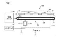
図1は、本開示の一実施形態としての液体吐出ヘッド26を備える液体吐出装置100の概略構成を示すブロック図である。本実施形態において、液体吐出装置100は、インクジェット式プリンターとして構成され、印刷用紙Pにインクを吐出して画像を形成する。なお、印刷用紙Pに代えて、樹脂フィルム、布帛等の任意の種類の媒体を、インクの吐出対象としてもよい。図1には、相互に直交する3つの軸であるX軸、Y軸およびZ軸が表されている。Z軸は、例えば、鉛直方向と平行に設定してもよい。他の図面に記載のX軸、Y軸およびZ軸は、いずれも図1のX軸、Y軸およびZ軸に対応する。向きを特定する場合には、正の方向を「+」、負の方向を「-」として、方向表記に正負の符合を併用する。正の方向および負の方向を「軸方向」とも呼ぶ。なお、Z軸方向は、本開示における第1方向の下位概念に相当し、X軸方向は、本開示における第2方向の下位概念に相当する。また、+Z方向は第1方向の一方側の下位概念に、-Z方向は第1方向の他方側の下位概念に、それぞれ相当する。なお、X軸、Y軸およびZ軸は、直交に限らず、任意の角度で交差していてもよい。
A. First embodiment:
A1. Overall configuration of the liquid ejection device:
FIG. 1 is a block diagram showing a schematic configuration of a
液体吐出装置100は、液体吐出ヘッド26と、インクタンク50と、搬送機構60と、移動機構70と、制御ユニット80とを備える。
The
液体吐出ヘッド26は、多数のノズルを有し、-Z方向にインクを吐出して印刷用紙P上に画像を形成する。液体吐出ヘッド26の詳細構成は後述する。吐出するインクとしては、例えば、ブラック、シアン、マゼンタ、イエローの合計4色のインクを吐出してもよい。なお、上記4色に限らずライトシアン、ライトマゼンタ、ホワイトなど、任意の色のインクを吐出してもよい。液体吐出ヘッド26は、移動機構70が有する後述のキャリッジ72に搭載され、キャリッジ72の移動と共に主走査方向に往復移動する。本実施形態において、主走査方向は、+Y方向および-Y方向である。+Y方向および-Y方向を「Y軸方向」とも呼ぶ。
The liquid ejection head 26 has a large number of nozzles, and ejects ink in the -Z direction to form an image on the printing paper P. The detailed configuration of the liquid ejection head 26 will be described later. The ejected ink may be, for example, a total of four colors of ink: black, cyan, magenta, and yellow. Note that the ink is not limited to the above four colors, and any color of ink may be ejected, such as light cyan, light magenta, and white. The liquid ejection head 26 is mounted on a carriage 72 (to be described later) of the
インクタンク50は、液体吐出ヘッド26から吐出するインクを収容する。インクタンク50は、キャリッジ72には搭載されていない。インクタンク50と液体吐出ヘッド26とは、樹脂製のチューブ52によって接続されており、かかるチューブ52を介してインクタンク50から液体吐出ヘッド26へとインクが供給される。なお、インクタンク50に代えて、可撓性フィルムで形成された袋状の液体パックを用いてもよい。
The
搬送機構60は、印刷用紙Pを副走査方向に搬送する。副走査方向は、主走査方向であるY軸方向と直交する方向であり、本実施形態では、+X方向および-X方向である。+X方向および-X方向を「X軸方向」とも呼ぶ。搬送機構60は、3つの搬送ローラー62が装着された搬送ロッド64と、搬送ロッド64を回転駆動する搬送用モーター66とを備える。搬送用モーター66が搬送ロッド64を回転駆動することにより、複数の搬送ローラー62が回転して印刷用紙Pが副走査方向である+Y方向に搬送される。なお、搬送ローラー62の数は3つに限らず任意の数であってもよい。また、搬送機構60を複数備える構成としてもよい。
The
移動機構70は、上述のキャリッジ72に加えて、搬送ベルト74と、移動用モーター76と、プーリー77とを備える。キャリッジ72は、インクを吐出可能な状態で液体吐出ヘッド26を搭載する。キャリッジ72は、搬送ベルト74に取り付けられている。搬送ベルト74は、移動用モーター76とプーリー77との間に架け渡されている。移動用モーター76が回転駆動することにより、搬送ベルト74は、主走査方向に往復移動する。これにより、搬送ベルト74に取り付けられているキャリッジ72も、主走査方向に往復移動する。
The
制御ユニット80は、液体吐出装置100の全体を制御する。例えば、制御ユニット80は、キャリッジ72の主走査方向に沿った往復動作や、印刷用紙Pの副走査方向に沿った搬送動作を制御する。本実施形態において、制御ユニット80は、後述の圧電アクチュエーターの駆動制御部としても機能する。すなわち、制御ユニット80は、液体吐出ヘッド26に駆動信号を出力して圧電アクチュエーターを駆動させることにより、印刷用紙Pへのインク吐出を制御する。制御ユニット80は、例えば、CPU(Central Processing Unit)またはFPGA(Field Programmable Gate Array)等の処理回路と半導体メモリー等の記憶回路とにより構成されてもよい。
The
A2.液体吐出ヘッドの詳細構成:
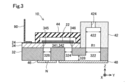
図2は、液体吐出ヘッド26の詳細構成を示す分解斜視図である。図3は、液体吐出ヘッド26の詳細構成を示す断面図である。図3では、図2に示す3-3断面を表している。なお、図2では、一色分の液体吐出ヘッド26の構成を例示している。したがって、吐出するインクの色数に応じて図2に示す液体吐出ヘッド26を複数備える構成としてもよい。また、各色について図2に示す液体吐出ヘッド26を複数備える構成としてもよい。
A2. Detailed configuration of liquid ejection head:
Fig. 2 is an exploded perspective view showing the detailed configuration of the liquid ejection head 26. Fig. 3 is a cross-sectional view showing the detailed configuration of the liquid ejection head 26. Fig. 3 shows the cross section taken along line 3-3 shown in Fig. 2. Note that Fig. 2 illustrates the configuration of the liquid ejection head 26 for one color. Therefore, a configuration may be adopted in which a plurality of liquid ejection heads 26 shown in Fig. 2 are provided according to the number of colors of ink to be ejected. Also, a configuration may be adopted in which a plurality of liquid ejection heads 26 shown in Fig. 2 are provided for each color.
図2に示すように、液体吐出ヘッド26は、ノズル板46と、吸振体48と、流路基板32と、圧力室基板34と、筐体部42と、封止体44と、圧電アクチュエーター20とを備える。
As shown in FIG. 2, the liquid ejection head 26 includes a
ノズル板46は、多数のノズルNがY軸方向に沿って一列に並んで形成されている薄板状の部材である。なお、ノズルNの列の数は、1つに限らず任意の数であってもよい。ノズルNは、ノズル板46において厚さ方向(Z軸方向)の貫通孔として形成されている。ノズルNは、液体吐出ヘッド26からのインクの吐出口に相当する。ノズル板46は、液体吐出ヘッド26において最も-Z方向に位置する。ノズル板46は、本実施形態では、ステンレス鋼(SUS)により形成されている。なお、ステンレス鋼に限らず、ニッケル(Ni)合金などの他の種類の金属、ポリイミドやドライフィルムレジストなどの樹脂材料、および珪素の単結晶基板などの無機材料等により形成されてもよい。
The
吸振体48は、弾性変形可能な可撓性を有するシート状の部材である。吸振体48は、ノズル板46と同様に液体吐出ヘッド26において最も-Z方向に位置し、ノズル板46と並んで配置されている。図3に示すように、吸振体48は、筐体部42の内部と流路基板32とに亘って形成される液体貯留室R1の圧力変形を吸収する。吸振体48は、流路基板32に形成された後述の開口部322と中継流路328と複数の供給流路324とを閉塞して、液体貯留室R1の底面を形成する。吸振体48としては、例えば、樹脂製のシート部材により構成してもよい。吸振体48は、コンプライアンス基板とも呼ばれる。
The
流路基板32は、インクの流路を形成するための板状部材である。図3に示すように、流路基板32の-Z方向の面は、ノズル板46と吸振体48とにそれぞれ接合されている。かかる接合は、例えば、接着剤を用いて実現されてもよい。本実施形態において、流路基板32は、珪素(Si)の単結晶基板により構成されている。なお、珪素の単結晶基板に限らず、珪素を主成分とする基板により形成されてもよい。図2および図3に示すように、流路基板32には、開口部322と供給流路324と連通流路326とが形成されている。
The
図2に示すように、開口部322は、Z軸方向に見たときに、X軸方向を長手方向とする略矩形の平面視形状を有する貫通孔として形成されている。開口部322は、各ノズルNに対応する供給流路324とY軸方向に対応する位置をすべて含むような1つの貫通孔として形成されている。図3に示すように、開口部322は、筐体部42の後述する収容部422と共に液体貯留室R1を形成する。液体貯留室R1は、チューブ52を介してインクタンク50から供給されるインクを一時的に貯留する。液体貯留室R1は、リザーバーとも呼ばれる。
As shown in FIG. 2, the
図2に示すように、供給流路324は、各ノズルNと+Y方向において対応する位置にそれぞれ形成されている。したがって、各供給流路324は、ノズルNと同様にX軸方向に並んで一列に配置されている。供給流路324は、流路基板32を厚さ方向に貫く貫通孔として形成されている。図3に示すように、流路基板32における-Z方向の表面、より詳細には、流路基板32における吸振体48側の表面には、開口部322と供給流路324との間に溝が形成されている。かかる溝と吸振体48とで囲まれる領域は、中継流路328として機能する。中継流路328により開口部322(液体貯留室R1)と供給流路324とは互いに連通する。中継流路328は、液体貯留室R1から供給流路324へとインクを中継する。供給流路324は、圧力室341と連通し、圧力室341にインクを供給する。
2, the
図2に示すように、連通流路326は、各ノズルNと+Z方向において対応する位置、および各供給流路324と-Y方向において対応する位置にそれぞれ形成されている。したがって、各連通流路326は、ノズルNおよび供給流路324と同様にX軸方向に並んで一列に配置されている。図3に示すように、連通流路326は、ノズルNおよび圧力室341とそれぞれ連通し、圧力室341のインクをノズルNに供給する。
As shown in FIG. 2, the
圧力室基板34は、圧力室341を形成するための板状部材である。図3に示すように、圧力室基板34の-Z方向の面は、流路基板32の+Z方向の面と接合されている。かかる接合は、接着剤を用いて実現されてもよい。本実施形態において、圧力室基板34は、流路基板32と同様に珪素の単結晶基板により構成されている。なお、珪素の単結晶基板に限らず、珪素を主成分とする基板により形成されてもよい。図2および図3に示すように、圧力室基板34には、複数の圧力室形成部342が形成されている。
The
各圧力室形成部342は、Z軸方向に見たときに、Y軸方向を長手方向とする略矩形の平面視形状を有する貫通孔として形成されている。各圧力室形成部342は、各ノズルNと+Z方向において対応する位置にそれぞれ形成されている。したがって、各圧力室形成部342は、ノズルNと同様にX軸方向に並んで一列に形成されている。圧力室形成部342は、圧電アクチュエーター20が備える後述の振動板24と接合することにより、圧力室341を形成する。各圧力室形成部342のY軸方向の側壁345および346は、圧力室341を区画する区画壁として機能する。圧力室341は、供給流路324と連通流路326とに連通し、供給流路324から供給されるインクを収容する。圧力室341の容積は、後述の振動板24が変形することにより変化する。
Each pressure
筐体部42は、一面が開口した中空の略四角柱状の外観形状を有する。本実施形態において、筐体部42は、樹脂により形成されている。図3に示すように、筐体部42は、流路基板32の+Z方向の面に接合されている。筐体部42の内側には収容部422が形成されている。収容部422の-Z方向は開口しており、収容部422は、かかる開口において開口部322と連通して液体貯留室R1を形成している。図2および図3に示すように、筐体部42の+Z方向の端部(天井部)には、導入口424が形成されている。導入口424は、筐体部42の+Z方向の端部を厚さ方向(Z軸方向)に貫き、液体貯留室R1と連通する。導入口424には、図1に示すチューブ52が接続される。なお、導入口424には、図示しないチューブを介して図示しないインク貯留部(例えば、サブタンク)が接続されてもよい。この構成では、インクタンク50からチューブ52を介してかかるインク貯留部にインクが供給されてもよい。
The
封止体44は、一面が開口した中空の略四角柱状の外観形状を有する。本実施形態において、封止体44は、樹脂により形成されている。図3に示すように、筐体部42は、自身の内側の空間に後述の圧電部22が収容されるように配置され、後述の振動板24の+Z方向の面に接合されている。封止体44は、圧電部22を保護すると共に、圧力室基板34、振動板24の一部の機械的強度を補強する。
The sealing
図3に示すように、液体吐出ヘッド26において、振動板24の+Z方向の面には、配線基板90が接続されている。配線基板90には、制御ユニット80および図示しない電源回路と接続するための複数の配線が形成されている。本実施形態において、配線基板90は、例えば、FPC(Flexible Printed Circuit)により構成されている。なお、FPCに代えて、FFC(Flexible Flat Cable)など、可撓性を有する任意の基板により構成されてもよい。配線基板90は、圧電アクチュエーター20を駆動するための駆動信号を各圧電アクチュエーター20に供給する。
As shown in FIG. 3, in the liquid ejection head 26, a
圧電アクチュエーター20は、自身が変形することによって圧力室341の容積を変化させ、圧力室341からインクを流出させる。
The
図4は、圧電アクチュエーター20の詳細構成を模式的に示す断面図である。図4では、説明の便宜上、液体吐出ヘッド26の圧力室基板34も図示している。圧電アクチュエーター20は、振動板24と、複数の圧電部22とを備える。
Figure 4 is a cross-sectional view showing a schematic diagram of the detailed configuration of the
振動板24は、弾性体層241と、絶縁層242とを備える。振動板24は、弾性体層241と絶縁層242とがZ軸方向に積層された構造を有する。弾性体層241は、圧力室基板34の+Z方向の面上に配置されている。絶縁層242は、弾性体層241の+Z方向の面上に配置されている。弾性体層241は、二酸化珪素(SiO2)により形成されている。絶縁層242は、酸化ジルコニウム(ZrO2)により形成されている。
The
圧電部22は、圧電体220と、第1電極221と、第2電極222とを備える。圧電部22は、振動板24と同様に、圧電体220、第1電極221および第2電極222の各層がZ軸方向に積層された構造を有する。
The
圧電体220は、圧電効果を有する材料により形成された膜状の部材であり、第1電極221および第2電極222に印加される電圧に応じて変形する。圧電体220は、振動板24の絶縁層242の+Z方向の一部の面と、第1電極221の+Z方向の面とを覆うように、配置されている。圧電体220は、X軸方向における中央近傍の部分において、+Z方向の面が+Z方向に若干突出しており、+Z方向から-Z方向に向かうにしたがってX軸方向の寸法が大きくなるテーパー形状に形成されている。
The
本実施形態において、圧電体220は、チタン酸ジルコン酸鉛(PZT)によって形成されている。なお、圧電体220は、チタン酸ジルコン酸鉛に代えて、ABO3型のペロブスカイト構造を有する他の種類のセラミックス、例えば、チタン酸バリウム、チタン酸鉛、ニオブ酸カリウム、ニオブ酸リチウム、タンタル酸リチウム、タングステン酸ナトリウム、酸化亜鉛、チタン酸バリウムストロンチウム(BST)、タンタル酸ストロンチウムビスマス(SBT)、メタニオブ酸鉛、亜鉛ニオブ酸鉛、スカンジウムニオブ酸鉛等によって形成されてもよい。また、圧電体220は、セラミックスに限らず、ポリフッ化ビニリデン、水晶など、圧電効果を有する任意の材料により形成されてもよい。
In this embodiment, the
第1電極221および第2電極222は、圧電体220を挟む一対の電極である。第1電極221は、圧電体220に対して振動板24側に位置し、振動板24の絶縁層242の+Z方向の面に設けられている。第1電極221は、圧力室341のX軸方向における中央を覆うように配置されている。第1電極221は、+Z方向から-Z方向に向かうにしたがってX軸方向の寸法が大きくなるテーパー形状に形成されている。第2電極222は、圧電体220に対して振動板24側とは反対側に位置し、圧電体220の+Z方向の面に設けられている。第2電極222は、圧電体220の外形を覆っている。
The
第1電極221および第2電極222は、いずれも配線基板90と電気的に接続され、配線基板90から供給される駆動信号に応じた電圧を、圧電体220に印加する。第1電極221には、インクの吐出量に応じて異なる駆動電圧が供給され、第2電極222には、インクの吐出量にかかわらず、一定の保持電圧が供給される。これにより、第1電極221と第2電極222との間に電位差が生じて、圧電体220が変形する。その結果、圧力室341が変形して、圧力室341に収容されているインクに圧力が付与され、連通流路326を介してノズルNからインクが吐出される。
The
本実施形態において、第1電極221は、配線基板90から各圧電アクチュエーター20に延びる個別配線に接続されている。第1電極221は、各圧電アクチュエーター20に個別に設けられる、いわゆる個別電極である。これに対して、第2電極222は、各圧電アクチュエーター20に共通する共通電極であり、配線基板90から延びる1つの共通配線に接続されている。上述の個別配線は、例えば、第1電極221の外側面に形成された絶縁層242に予めコンタクトホールを設けておき、かかるコンタクトホールを介して第1電極221と接してもよい。また、上述の共通電極は、例えば、第2電極222を-Z方向に見たときに圧電体220よりも若干大きく形成し、第2電極222における+Z方向に圧電体220が存在しない部分に絶縁層を形成し、かかる絶縁層に予めコンタクトホールを設けておき、かかるコンタクトホールを介して各圧電アクチュエーター20の第2電極222と接してもよい。
In this embodiment, the
本実施形態において、第1電極221および第2電極222は、白金(Pt)により形成されている。なお、白金に代えて、金(Au)やイリジウム(Ir)などの導電性を有する任意の材料で形成されてもよい。
In this embodiment, the
図4に示すように、圧力室341内のX軸方向における中央部の領域Ar1には、-Z方向から+Z方向に向かって順に、振動板24、第1電極221、圧電体220および第2電極222が並んで設けられている。また、圧力室341内のX軸方向における端部の2つの領域Ar2には、それぞれ、-Z方向から+Z方向に向かって順に、振動板24、圧電体220および第2電極222が並んで設けられている。すなわち、領域Ar1および領域Ar2には、いずれも、振動板24と圧電体220との両方が設けられている。
As shown in FIG. 4, in the central region Ar1 in the X-axis direction of the pressure chamber 341, the
本実施形態において、領域Ar1は、第1電極221および第2電極222への電圧の印加により撓みが生じる能動部に対応する領域であり、例えば、圧力室341のX軸方向における中央部の領域である。領域Ar1のX軸方向の長さは、第1電極221のX軸方向の長さとほぼ同じである。また、領域Ar2は、領域Ar1に対してX軸方向外側、すなわち、領域Ar1に対して-X方向と、領域Ar1に対して+X方向とに位置し、領域Ar1よりも圧力室341の区画壁345、346に近い領域である。領域Ar2は、非能動部に対応する領域でもある。領域Ar2としては、例えば、圧力室341のX軸方向における2つの端部の領域とすることができる。図4に示すように、領域Ar1には、圧力室341内のX軸方向の中央の位置P1が含まれる。領域Ar2には、X軸方向において区画壁345と重なる位置P3と、領域Ar1内の位置P1よりも区画壁345に近い位置に位置する位置P2とが含まれる。位置P1および位置P2は、圧力室341内のX軸方向における或る2つの位置のうち、X軸方向において最も近い位置に位置する区画壁345までのX軸方向の距離が長い位置が位置P1であり、かかる距離が短い位置が位置P2である。以降の説明において、領域Ar1を第1領域Ar1、領域Ar2を第2領域Ar2、位置P1を第1位置P1、位置P2を第2位置P2、位置P3を第3位置P3とも呼ぶ。
In this embodiment, the region Ar1 corresponds to an active part where bending occurs due to application of a voltage to the
図4に示すように、振動板24は、第1領域Ar1における+Z方向の面が、第2領域Ar2における+Z方向の面よりも+Z方向に若干突出した凸形状となるように形成されている。したがって、振動板24は、第1領域Ar1における厚さと、第2領域Ar2における厚さとが異なっている。また、圧電体220も同様に、第1領域Ar1における+Z方向の面が、第2領域Ar2における+Z方向の面よりも+Z方向に若干突出した凸形状となるように形成され、第1領域Ar1における厚さと、第2領域Ar2における厚さとが異なっている。本実施形態において、振動板24および圧電体220の厚さを、第1領域Ar1と第2領域Ar2とで異ならせるのは、以下の理由による。
As shown in FIG. 4, the
本開示の発明者らは、圧電体220を第1領域Ar1および第2領域Ar2に設けることを前提とした上で、振動板24の剛性を向上させることにより、クラックの発生をより抑制することを考えた。そして、本開示の発明者らは、振動板24の剛性を高めるために単に振動板24の厚さを大きくする場合、様々な不具合が生じ得ることを見出した。例えば、圧力室基板34に圧力室341を形成する際に、振動板24に反りが生じて製造工程が複雑化するといった問題や、圧電アクチュエーター20の中立軸、例えば、第2領域Ar2における中立軸が振動板24側に配置されると、振動板24の弾性体層241と絶縁層242との境界面において、絶縁層242が弾性体層241側に引っ張られてクラックが発生するといった問題が生じ得る。なお、以降の説明における中立軸とは、Z軸方向における位置を示しているが、単に中立軸と記載する。
The inventors of the present disclosure have considered how to further suppress the occurrence of cracks by improving the rigidity of the
研究の結果、本開示の発明者らは、以下の4つのことを見出した。
(1)クラックの発生を抑制するためには、第1領域Ar1および第2領域Ar2に圧電体220と振動板24との両方を設けることが好ましいこと、
(2)第1領域Ar1においては、中立軸を圧電体220よりも振動板24側に寄った位置に配置することにより、液体吐出ヘッド26の吐出特性を保てること、
(3)第2領域Ar2においては、中立軸を振動板24よりも圧電体220側に寄った位置に配置することにより、クラックの発生を抑制できること、
(4)上記(2)および(3)を実現するために圧電体220の厚さを従来から大きく変更する場合には、圧電部22の圧電性能が低下し、また、製造工程が複雑になること。
As a result of their research, the inventors of the present disclosure discovered the following four things.
(1) In order to suppress the occurrence of cracks, it is preferable to provide both the
(2) In the first region Ar1, the neutral axis is disposed at a position closer to the
(3) In the second region Ar2, the neutral axis is disposed at a position closer to the
(4) If the thickness of the
そして、本開示の発明者らは、振動板24の厚さを制御することにより、第1領域Ar1における中立軸の配置位置と、第2領域Ar2における中立軸の配置位置とを別々に制御可能であるとの新たな知見を得た。具体的には、第2領域Ar2における振動板24の厚さを、第1領域Ar1における振動板24の厚さよりも小さくすることにより、上記(2)および(3)を充足できる、というものである。以下、具体的に説明する。
The inventors of the present disclosure have now discovered that it is possible to separately control the position of the neutral axis in the first region Ar1 and the position of the neutral axis in the second region Ar2 by controlling the thickness of the
図5は、圧電アクチュエーター20の拡大図である。なお、説明の便宜上、図5では、ハッチングの図示を省略している。図5に示すように、第2位置P2における振動板24の厚さd2は、第1位置P1における振動板24の厚さd1よりも小さい。具体的には、第2位置P2における弾性体層241の厚さd21は、第1位置P1における弾性体層241の厚さd11よりも小さい。また、第2位置P2における絶縁層242の厚さd22は、第1位置P1における絶縁層242の厚さd12と等しい。なお、第1位置P1において、弾性体層241の厚さd11は、例えば、1600ナノメートルであり、絶縁層242の厚さd12は、例えば、100ナノメートルである。第2位置P2において、弾性体層241の厚さd21は、例えば、400ナノメートルであり、絶縁層242の厚さd22は、例えば、100ナノメートルである。
Figure 5 is an enlarged view of the
第2領域Ar2において、第3位置P3における振動板24の厚さd3は、第2位置P2における振動板24の厚さd2と同じである。具体的には、第3位置P3における弾性体層241の厚さd31は、第2位置P2における弾性体層241の厚さd21と同じである。また、第3位置P3における絶縁層242の厚さd32は、第2位置P2における絶縁層242の厚さd22と同じである。したがって、第3位置P3における振動板24の厚さd3は、第2位置P2と同様に、第1位置P1における振動板24の厚さd1よりも小さい。
In the second region Ar2, the thickness d3 of the
図4および図5に示すように、振動板24の-Z方向の面、すなわち、弾性体層241の-Z方向の面は、X軸方向と平行である。したがって、図5に示すように、第1位置P1、第2位置P2および第3位置P3において、振動板24の-Z方向の端部E5は、Z軸方向において同じ位置に配置されている。
As shown in Figures 4 and 5, the -Z direction surface of the
これに対して、振動板24の+Z方向の面、すなわち、絶縁層242の+Z方向の面は、第1領域Ar1において、第2領域Ar2における+Z方向の位置よりも更に+Z方向に位置している。具体的には、第1位置P1における絶縁層242の+Z方向の端部E1は、第2位置P2における絶縁層242の+Z方向の端部E3よりも、圧電体220側に配置されている。換言すると、第2位置P2における絶縁層242の+Z方向の端部E3は、第1位置P1における絶縁層242+Z方向の端部E1よりも、-Z方向に配置されている。
In contrast, the +Z direction surface of the
また、弾性体層241の+Z方向の面も同様に、第1領域Ar1において、第2領域Ar2における+Z方向の位置よりも更に+Z方向に位置している。具体的には、第1位置P1における弾性体層241の+Z方向の端部E2は、第2位置P2における弾性体層241の+Z方向の端部E4よりも、圧電体220側に配置されている。換言すると、第2位置P2における弾性体層241の+Z方向の端部E4は、第1位置P1における弾性体層241の+Z方向の端部E2よりも、-Z方向に配置されている。
Similarly, the +Z direction surface of the
したがって、本実施形態では、振動板24の-Z方向の端部E5よりも+Z方向において、第1領域Ar1の+Z方向の端部E1を第2領域Ar2の+Z方向の端部E3よりも+Z方向に配置することにより、第2領域Ar2における振動板24の厚さを、第1領域Ar1における振動板24の厚さよりも小さくしていると言うことができる。
Therefore, in this embodiment, by positioning the +Z direction end E1 of the first region Ar1 further in the +Z direction than the -Z direction end E5 of the
圧電体220の厚さについても、振動板24と同様に、第2位置P2における圧電体220の厚さd5は、第1位置P1における圧電体220の厚さd4よりも小さい。第2位置P2における圧電体220の厚さd5は、第2位置P2における振動板24の厚さd2よりも大きい。第1位置P1における圧電体220の厚さd4は、第1位置P1における振動板24の厚さd1よりも小さい。なお、第3位置P3における圧電体220の厚さd6は、第2位置P2における圧電体220の厚さd5と同じである。なお、第1位置P1における圧電体220の厚さd4は、例えば、1200ナノメートルであり、第2位置P2における圧電体220の厚さd5および第3位置P3における圧電体220の厚さd6は、例えば、600ナノメートルである。
As for the thickness of the
したがって、第2領域Ar2における振動板24の厚さd2と圧電体220の厚さd5との合計は、第1領域Ar1における振動板24の厚さd1と圧電体220の厚さd4との合計よりも小さくなる。また、第2位置P2における振動板24の厚さd2と第2位置P2における圧電体220の厚さd5との合計は、第1位置P1における振動板24の厚さd1よりも大きく、第1位置P1における圧電体220の厚さd4よりも大きい。したがって、第2位置P2における振動板24の厚さd2と圧電体220の厚さd5との差分は、第1位置P1における振動板24の厚さd1と第1位置P1における圧電体220の厚さd4との差分よりも小さくなる。
Therefore, the sum of the thickness d2 of the
以上説明したように、このような構成の圧電アクチュエーター20では、第1位置P1を含む第1領域Ar1においては、中立軸を、圧電体220よりも振動板24側に寄った位置に配置することができるとともに、第2位置P2および第3位置P3を含む第2領域Ar2においては、中立軸を、振動板24よりも圧電体220側に寄った位置に配置することができる。なお、第1領域Ar1における圧電アクチュエーター20の中立軸は振動板24内に位置し、第2領域Ar2における圧電アクチュエーター20の中立軸は圧電体220内に位置することがより好ましい。
As described above, in the
A3.液体吐出ヘッドの製造方法:
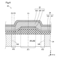
図6、図7、図8および図9は、液体吐出ヘッド26の製造方法を示す工程図である。図6、図7、図8および図9では、液体吐出ヘッド26の製造工程のうち、圧電アクチュエーター20の製造工程を示している。図6に示すように、工程P105において、圧力室形成部342が形成される前の圧力室基板34の+Z方向の面に、振動板24が形成される。具体的には、振動板24は、MEMS(Micro Electro Mechanical Systems)の製造に係る微細加工技術を用いて形成される。まず、熱酸化により圧力室基板34の表面に弾性体層241を形成する。弾性体層241の厚さは、例えば、1700ナノメートルに形成されることが好ましい。なお、熱酸化に代えてCVD(Chemical Vapor Deposition)法により弾性体層241を形成してもよい。
A3. Manufacturing method of liquid ejection head:
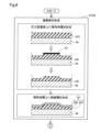
6, 7, 8, and 9 are process diagrams showing a method for manufacturing the liquid ejection head 26. In FIG. 6, 7, 8, and 9, the manufacturing process of the
次に、弾性体層241をパターニングする。具体的には、フォトリソグラフィを用いたレジストPrの形成、エッチング、およびレジストPrの剥離といった、公知の加工技術を用いて、弾性体層241の、X軸方向における中央部(上述の第1領域Ar1に相当する部分)に、圧力室基板34に対して凸となる段差が形成される。より具体的には、弾性体層241における中央部のX軸方向外側の端部(上述の第2領域Ar2に相当する部分)の厚さが、中央部における厚さよりも小さくなるように、端部の表面が削られる。弾性体層241の端部における厚さは、例えば、500ナノメートルに形成されることが好ましい。なお、エッチングとしては、フッ化水素(HF)を含むエッチング液を用いた液体エッチングでもよいし、ドライエッチングでもよい。
Next, the
次に、弾性体層241の表面をエッチングして表面を滑らかにする。具体的には、弾性体層241のパターニングによって形成された段差の角部や、レジストPrが載置されていた部分の表面が平滑になるように加工される。このとき、弾性体層241の厚さは、例えば、中央部が1700ナノメートル、端部が400ナノメートルに形成されることが好ましい。
Next, the surface of the
次に、段差が形成された弾性体層241の表面に、絶縁層242をCVD法により形成する。絶縁層242は、100ナノメートルの厚さに形成されることが好ましい。このようにして、圧力室基板34の表面に振動板24が形成される。
Next, an insulating
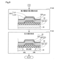
図7に示すように、工程P110において、振動板24の+Z方向の表面に第1電極221が形成される。具体的には、白金をターゲット材としたスパッタリングにより第1電極221を形成する。第1電極221は、200ナノメートルの厚さに形成されることが望ましい。
As shown in FIG. 7, in process P110, a
工程P115において、第1電極221の+Z方向の表面に圧電体220の第1層L21が形成される。圧電体220は、ゾルゲル法を用いて形成される。具体的には、圧電体220の基材としての鉛(Pb)、ジルコニウム(Zr)およびチタン(Ti)を含有する有機金属化合物を溶媒に溶解させた溶液を、第1電極221の表面にスピンコートし、その後、固化のための焼成を行う。これによりチタン酸ジルコン酸鉛(PZT)の層が一層分形成される。圧電体220の第1層L21は、200ナノメートルの厚さに形成されることが好ましい。
In process P115, the first layer L21 of the
工程P120において、第1電極221および圧電体220の第1層L21がパターニングされる。工程P120は、上述の工程P105における振動板24の弾性体層241のパターニングと同様の手順により行われる。このとき、第1電極221および圧電体220の第1層L21の形状が、+Z方向から-Z方向に向かうにしたがってX軸方向の寸法が大きくなるテーパー形状となるように、第1電極221および圧電体220の表面が加工される。
In process P120, the
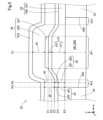
図8に示すように、工程P125において、圧電体220の第2層以降の層L2nが形成される。工程P125は、上述の工程P115と同様の手順により行われる。具体的には、段差が形成された状態の振動板24の+Z方向の表面と、圧電体220の第1層L21の+Z方向の表面とに、上述の溶液のスピンコートおよび固化のための焼成を複数回繰り返し行ってチタン酸ジルコン酸鉛の層を複数形成し、その後、結晶化のための焼成を行う。このような工程を所定の厚さを得るまで繰り返し実行することにより、圧電体220の層を複数積層する。圧電体220は、1000ナノメートルの厚さに形成されることが好ましい。
As shown in FIG. 8, in step P125, the second and subsequent layers L2n of the
工程P130において、圧電体220の+Z方向の表面に第2電極222の第1層L31が形成される。具体的には、白金をターゲット材としたスパッタリングにより第2電極222を形成する。第2電極222の第1層L31は、10ナノメートルの厚さに形成されることが好ましい。
In process P130, the first layer L31 of the
工程P135において、圧電体220および第2電極222の第1層L31がパターニングされる。パターニングは、上述の工程P105および工程P120と同様の手順により行われる。工程P135では、圧電体220のX軸方向における中央部の形状が、+Z方向から-Z方向に向かうにしたがってX軸方向の寸法が大きくなるテーパー形状となるように、圧電体220の端部の表面が削られる。また、第2電極222が、X軸方向における中央部にのみ配置されるように、すなわち、Z軸方向において第1電極221と対応する位置にのみ配置されるように、第2電極222の端部が圧電体220の+Z方向の表面から剥離される。圧電体220における端部は、600ナノメートルの厚さに形成されることが好ましい。なお、工程P135では、第2電極222のアニール処理を行ってもよい。
In process P135, the first layer L31 of the
図9に示すように、工程P140において、圧電体220の+Z方向の表面および第2電極222の第1層L31の+Z方向の表面に、第2電極222の第2層L32が形成される。工程P140は、上述の工程P130と同様の手順により行われる。第2電極222の第2層L32は、30ナノメートルの厚さに形成されることが好ましい。
As shown in FIG. 9, in process P140, the second layer L32 of the
工程P145において、圧力室基板34に圧力室形成部342を形成する。圧力室形成部342の形成は、例えば、フォトリソグラフィを用いたレジストの形成、エッチング、およびレジストの剥離といった、公知の加工技術を用いて実行される。
In process P145, a pressure
図示は省略しているが、工程P145の後、次の手順により液体吐出ヘッド26が製造される。具体的には、予め開口部322、供給流路324、連通流路326、および中継流路328を構成する溝が形成された流路基板32を、圧力室基板34に接合する。開口部322等の形成は、上述の供給流路324の形成と同様に公知の加工技術を用いて実行される。流路基板32と圧力室基板34との接合は、例えば接着剤を用いて実行されてもよい。次に、ノズル板46および吸振体48が、流路基板32に接合される。次に、予め収容部422および導入口424が形成された筐体部42が流路基板32の+Z方向の表面に接合される。次に、封止体44が振動板24の+Z方向の表面に接合される。次に、配線基板90が振動板24の+Z方向の表面に接合される。このようにして、液体吐出ヘッド26が完成する。
Although not shown in the figure, after process P145, the liquid ejection head 26 is manufactured by the following procedure. Specifically, the
液体吐出ヘッド26を備えた液体吐出装置100の製造の際には、配線基板90と制御ユニット80とが接続され、導入口424とチューブ52とが接続される。
When manufacturing the
以上説明した本実施形態の液体吐出ヘッド26によれば、圧力室341内におけるX軸方向の中央の領域を第1領域Ar1とし、第1領域Ar1のX軸方向外側の端部の領域を第2領域Ar2としたとき、第1領域Ar1および第2領域Ar2には、いずれも圧電体220と振動板24との両方が設けられているので、第1領域Ar1に圧電体220および振動板24の両方が設けられ、第2領域Ar2には圧電体220のみが設けられている構成に比べて、圧電体220が変形する際に、第1領域Ar1と第2領域Ar2との境界近傍において振動板24に応力が集中して、振動板24にクラックが発生することを抑制できる。また、この形態の液体吐出ヘッド26によれば、第2領域Ar2における振動板24の厚さd2は、第1領域Ar1における振動板24の厚さd1よりも小さいので、第1領域Ar1における中立軸を圧電体220よりも振動板24側に寄った位置に、また、第2領域Ar2における中立軸を振動板24よりも圧電体220側に寄った位置に、それぞれ配置できる。したがって、振動板24の中立面、すなわち、圧電体220により振動板24に曲げモーメントが加えられた際に振動板24が負荷を受けない部分が、第1領域Ar1においては圧電体220側の場所に位置し、第2領域Ar2においては、振動板24側の場所に位置することになる。このため、第1領域Ar1と第2領域Ar2とで、圧電体220が変形する際に応力の影響を受けない部分を異なる位置に配置することができるので、振動板24全体として剛性を高めることができる。
According to the liquid ejection head 26 of the present embodiment described above, when the central region in the X-axis direction within the pressure chamber 341 is defined as the first region Ar1 and the region at the outer end of the first region Ar1 in the X-axis direction is defined as the second region Ar2, both the first region Ar1 and the second region Ar2 are provided with both the
第2領域Ar2における振動板24の厚さd2と圧電体220の厚さd5との合計は、第1領域Ar1における振動板24の厚さd1と圧電体220の厚さd4との合計よりも小さいので、振動板24と圧電体220との全体の厚さに着目した場合であっても、振動板24の厚さのみに着目した場合や、圧電体220の厚さのみに着目した場合と同様に、第1領域Ar1における厚さを第2領域Ar2における厚さよりも大きくすることができる。
The sum of the thickness d2 of the
第2領域Ar2における圧電体220の厚さd5は、第1領域Ar1における圧電体220の厚さd4よりも小さいので、第1領域Ar1および第2領域Ar2に同じ厚さの圧電体を備える構成に比べて、圧電体220の変形効率の低下を抑制できる。
The thickness d5 of the
第2領域Ar2における振動板24の厚さd2と圧電体220の厚さd5との差分は、第1領域Ar1における振動板24の厚さd1と圧電体220の厚さd4との差分よりも小さいので、第2領域Ar2における中立軸を振動板24よりも圧電体220側に寄った場所に配置できる。
The difference between the thickness d2 of the
第2領域Ar2における振動板24の厚さd2と圧電体220の厚さd5との合計は、第1領域Ar1における振動板24の厚さd1よりも大きく、且つ、圧電体220の厚さd4よりも大きいので、第2領域Ar2における振動板24および圧電体220の全体の厚さを、第1領域Ar1における振動板24の厚さd1と、第1領域Ar1における圧電体220の厚さd4と、のそれぞれの厚さよりも大きくすることができる。
The sum of the thickness d2 of the
第2領域Ar2における振動板24の-Z方向の端部E5は、第1領域Ar1における振動板24の-Z方向の端部E5と同じ位置に配置され、第2領域Ar2における振動板24の+Z方向の端部E3は、第1領域Ar1における振動板24の+Z方向の端部E1よりも-Z方向に配置されているので、振動板24の+Z方向において振動板24の厚みを形成できる。このため、振動板24と圧力室基板34との物理的な密着度の低下を抑制できる。
The -Z direction end E5 of the
第2領域Ar2における絶縁層242の厚さd22は、第1領域Ar1における絶縁層242の厚さd12と等しく、第2領域Ar2における弾性体層241の厚さd21は、第1領域Ar1における弾性体層241の厚さd11よりも小さいので、弾性体層241の厚さを第1領域Ar1と第2領域Ar2とで異ならせることにより、振動板24全体の厚さを第1領域Ar1と第2領域Ar2とで異ならせることができる。
The thickness d22 of the insulating
絶縁層242が酸化ジルコニウムにより構成されているので、振動板24の機械的強度を向上できる。
The insulating
複数の圧力室341に対して個別に設けられる第1電極221と、複数の圧力室341に対して共通に設けられる第2電極222とを有しているので、第1電極221と第2電極222とを別々に駆動制御することにより、複数の圧力室341を別々に制御する構成と、複数の圧力室341を一括して制御する構成とを容易に実現できる。
Since the device has a
インクの吐出量に応じて異なる駆動電圧を第1電極221に印加し、かつ、インクの吐出量によらず一定の保持電圧を第2電極222に印加することにより、圧電体220を駆動するので、第1電極221と第2電極222との間に電位差を発生させることができる。したがって、かかる電位差により圧電体220を変形させることができるので、圧力室341に収容されているインクに圧力を付与できる。
By applying a driving voltage to the
X軸方向において区画壁345と重なる位置を第3位置P3としたとき、第3位置P3には、圧電体220と振動板24との両方が設けられ、第3位置P3における振動板24の厚さd3は、第1領域Ar1における振動板24の厚さd1よりも小さいので、第3位置P3における中立軸の位置を、第1領域Ar1における中立軸の位置よりも振動板24側の位置に配置できる。
When the position overlapping with the
第1領域Ar1は、圧力室341内のX軸方向における中央部であり、第2領域Ar2は、圧力室341内のX軸方向における端部であるので、圧力室341内のX軸方向における中央部と端部とで、振動板24の中立面の場所を異ならせることができる。このため、圧電体220が変形する際に、中央部と端部との境界近傍に応力が集中した場合であっても、かかる境界近傍において振動板24にクラックが発生することを抑制できる。
The first region Ar1 is the center of the pressure chamber 341 in the X-axis direction, and the second region Ar2 is an end of the pressure chamber 341 in the X-axis direction, so that the location of the neutral plane of the
以上説明した本実施形態の液体吐出ヘッド26の製造方法によれば、圧力室基板34の+Z方向の面に弾性体層241を形成し、形成された弾性体層241をエッチングすることにより、X軸方向の中央部が圧力室基板34に対して凸となるように段差を形成し、段差が形成された弾性体層241の+Z方向に圧電体220を形成するので、圧電体220におけるX軸方向の中央部が圧力室基板34に対して凸となるように圧電体220を形成できる。また、X軸方向の中央部における弾性体層241の厚さがX軸方向の端部における弾性体層241の厚さよりも大きくなるように段差が形成されるので、X軸方向の中央部の厚さがX軸方向の端部の厚さに比べて大きな振動板24を容易に形成できる。
According to the manufacturing method of the liquid ejection head 26 of this embodiment described above, the
B.第2実施形態:
以下では、上述の第1実施形態と同様の構成には同じ符号を用い、説明を省略する。図10は、第2実施形態における液体吐出ヘッドが備える圧電アクチュエーター20aの詳細構成を模式的に示す断面図である。図10では、図4に示す圧電アクチュエーター20の構成に対応する構成を示している。なお、後に参照する図においても同様である。第2実施形態の圧電アクチュエーター20aは、振動板24に代えて振動板24aを備える点において、第1実施形態の圧電アクチュエーター20と異なる。振動板24aは、弾性体層241に代えて弾性体層241aを備える点において、第1実施形態の振動板24と異なる。
B. Second embodiment:
In the following, the same reference numerals are used for the same configuration as in the first embodiment described above, and the description will be omitted. Fig. 10 is a cross-sectional view showing a schematic detailed configuration of a
図4および図5と、図10とを比較して理解できるように、第1領域Ar1において、第1位置P1における振動板24aの厚さd1aは、第1実施形態の振動板24の厚さd1に比べて大きい。具体的には、第1位置P1における弾性体層241aの厚さd11aは、第1実施形態の弾性体層241の厚さd11に比べて大きい。本実施形態では、第1位置P1における弾性体層241aの厚さd11aは、弾性体層241aの第2位置P2における+Z方向の端部E4よりも+Z方向において、弾性体層241aの厚さを大きくすることにより、第1実施形態の厚さd11よりも大きくしている。第1位置P1における弾性体層241aの厚さd11aは、第2位置P2における弾性体層241aの厚さd21よりも大きい。また、第1位置P1における弾性体層241aの厚さd11aは、第2位置P2における絶縁層242の厚さd22よりも大きい。したがって、第2実施形態においても、第2領域Ar2における振動板24aの厚さd2は、第1領域Ar1における振動板24aの厚さd1aよりも小さい。
4 and 5, and FIG. 10, in the first region Ar1, the thickness d1a of the
第2実施形態の圧電アクチュエーター20aは、図6に示す工程P105において、弾性体層241aのパターニングを省略することにより形成できる。したがって、弾性体層241aのエッチングを行うことによって生じる振動板24aの変位量のばらつきを低減できる。
The
C.第3実施形態:
図11は、第3実施形態における液体吐出ヘッドが備える圧電アクチュエーター20bの詳細構成を模式的に示す断面図である。第3実施形態の圧電アクチュエーター20bは、圧電部22に代えて圧電部22bを備える点において、第1実施形態の圧電アクチュエーター20と異なる。圧電部22bは、第1電極221に代えて第1電極221bを備える点において、第1実施形態の圧電部22と異なる。第1電極221bは、形状と、X軸方向における長さとが第1実施形態の第1電極221と異なる。
C. Third embodiment:
11 is a cross-sectional view showing a schematic detailed configuration of a
第1電極221bは、第1領域Ar1における振動板24の+Z方向を覆い、また、X軸方向において第1領域Ar1と第2領域Ar2とに挟まれる部分における振動板24の+Z方向を覆っている。すなわち、第1電極221bは、振動板24の+Z方向に突出した凸状の部位の外形を覆っている。第1電極221bは、第1実施形態の第1電極221に比べて、X軸方向の長さ(幅)が大きい。第1電極221bの-X方向の端部は、第1領域Ar1の-X方向に位置する第2領域Ar2の+X方向の端部と同じ位置に配置され、第1電極221bの+X方向の端部は、第1領域Ar1の+X方向に位置する第2領域Ar2の-X方向の端部と同じ位置に配置されている。したがって、第1電極221bは、第1領域Ar1と第2領域Ar2との境界近傍を覆っている。このため、かかる境界近傍において、第1電極221bが振動板24を保護することができるので、圧電体220が変形する際に振動板24にクラックが発生することを抑制できる。
The
第3実施形態の圧電アクチュエーター20bは、図7に示す工程P120において、第1電極221bの形状と同じ形状のマスクパターンを準備して、パターニングを行うことにより形成できる。
The
D.第4実施形態:
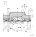
図12は、第4実施形態における液体吐出ヘッドが備える圧電アクチュエーター20cの詳細構成を模式的に示す断面図である。第4実施形態の圧電アクチュエーター20cは、振動板24に代えて振動板24cを備える点において、第1実施形態の圧電アクチュエーター20と異なる。振動板24cは、弾性体層241に代えて弾性体層241cを備える点と、密着層243を追加して備える点とにおいて、第1実施形態の振動板24と異なる。
D. Fourth embodiment:
12 is a cross-sectional view showing a schematic detailed configuration of a
第1実施形態において弾性体層241の+Z方向の面は、+Z方向に突出する凸状に形成されていた。これに対して、第4実施形態の弾性体層241cは、-Z方向の面と同様に、X軸方向と平行である。したがって、弾性体層241cの厚さは、X軸方向において一定である。すなわち、第1領域Ar1における弾性体層241cの厚さd11cは、第2領域Ar2における弾性体層241cの厚さd21と等しい。
In the first embodiment, the +Z direction surface of the
密着層243は、弾性体層241cと絶縁層242との間に設けられている。具体的には、密着層243は、弾性体層241cの+Z方向の面に配置され、絶縁層242は、密着層243の+Z方向の面に配置されている。密着層243は、例えば、酸化チタン(TiO2)や、酸化アルミニウム(Al2O3)により形成されている。密着層243は、図4に示す第1実施形態の弾性体層241と同様に、第1領域Ar1における+Z方向の面が、第2領域Ar2における+Z方向の面よりも+Z方向に若干突出した凸形状となるように形成されている。したがって、第2領域Ar2における密着層243の厚さd23は、第1領域Ar1における密着層243の厚さd13より小さい。
The
したがって、第4実施形態においても、第2領域Ar2における振動板24cの厚さd2cは、第1領域Ar1における振動板24cの厚さd1cよりも小さい。
Therefore, even in the fourth embodiment, the thickness d2c of the
第4実施形態の圧電アクチュエーター20cは、図6に示す工程P105において、圧力室基板34の表面に弾性体層241cを形成する際に弾性体層241のパターニングを省略し、形成された弾性体層241cの+Z方向の表面に熱酸化や、CVD法により密着層243を形成する。そして、形成された密着層243をパターニングする。密着層243のパターニングでは、第1実施形態の弾性体層241のパターニングに用いるマスクパターンと同じマスクパターンを用いてもよい。次に、密着層243上に絶縁層242を形成する。このようにして、密着層243を備える振動板24cが形成される。
In the
以上説明した第4実施形態の液体吐出ヘッドによれば、第2領域Ar2における絶縁層242の厚さはd22、第1領域Ar1における絶縁層242の厚さd12と等しく、第2領域Ar2における弾性体層241cの厚さd21は、第1領域Ar1における弾性体層241cの厚さd11cと等しく、第2領域Ar2における密着層243の厚さd23は、第1領域Ar1における密着層243の厚さd13よりも小さいので、密着層243の厚さを第1領域Ar1と第2領域Ar2とで異ならせることにより、振動板24c全体の厚さを第1領域Ar1と第2領域Ar2とで異ならせることができる。
According to the liquid ejection head of the fourth embodiment described above, the thickness d22 of the insulating
E.第5実施形態:
図13は、第5実施形態における液体吐出ヘッドが備える圧電アクチュエーター20dの詳細構成を模式的に示す断面図である。第5実施形態の圧電アクチュエーター20dは、圧電部22に代えて圧電部22dを備える点において、第1実施形態の圧電アクチュエーター20と異なる。圧電部22dは、第1電極221に代えて第1電極221dを備える点と、第2電極222に代えて第2電極222dを備える点とにおいて、第1実施形態の圧電部22と異なる。
E. Fifth embodiment:
13 is a cross-sectional view showing a schematic detailed configuration of a
第1実施形態では、第1電極221が個別電極であり、第2電極222が共通電極であった。これに対して、第5実施形態では、第1電極221dが共通電極であり、第2電極222dが個別電極である。第1電極221dは、共通配線により配線基板90と接続され、第2電極222dが個別配線によりそれぞれ配線基板90と接続されている。第1電極221dは、振動板24の絶縁層242の+Z方向の面に設けられ、X軸方向の全域に亘って絶縁層242の外形を覆っている。第2電極222dは、第1領域Ar1において圧電体220の+Z方向の面に設けられ、+Z方向から-Z方向に向かうにしたがってX軸方向の寸法が大きくなるテーパー形状に形成されている。
In the first embodiment, the
第5実施形態の圧電アクチュエーター20dは、以下の手順により形成できる。具体的には、第1電極221dは、上述の工程P120において第1電極221dのパターニングを省略することにより形成できる。すなわち、上述の工程P110において第1電極221dを形成し、上述の工程P115において圧電体220の第1層L21を形成し、上述の工程P120において圧電体220のみをパターニングする。また、第2電極222dは、上述の工程P135と、上述の工程P140との実行順序を入れ替えることにより形成できる。すなわち、上述の工程P130において第2電極222dの第1層L31を形成し、上述の工程P140において第2電極222dの第2層L32を形成し、上述の工程P135において圧電体220と第2電極222dとをパターニングする。このようにして、第1電極221dが共通電極であり、第2電極222dが個別電極である圧電部22dが形成される。
The
以上説明した第5実施形態の液体吐出ヘッドによれば、複数の圧力室341に対して個別に設けられる第2電極222dと、複数の圧力室341に対して共通に設けられる第1電極221dとを有しているので、第1電極221dと第2電極222dとを別々に駆動制御することにより、複数の圧力室341を別々に制御する構成と、複数の圧力室341を一括して制御する構成とを容易に実現できる。
The liquid ejection head of the fifth embodiment described above has a
F.他の実施形態:
(F1)上記各実施形態において、第1領域Ar1は、圧力室341内のX軸方向における中央部の領域であり、第2領域Ar2は、圧力室341内のX軸方向における端部の領域であったが、本開示はこれに限定されない。具体的には、第1領域Ar1を、圧力室341におけるX軸方向の中央部よりも端部に寄った領域、例えば、圧電体220のテーパー状に形成された部分に対応する領域とし、第2領域Ar2を、かかる第1領域Ar1よりも区画壁345、346に近い位置を含む領域としてもよい。すなわち、一般には、第1領域Ar1を圧力室341内のX軸方向における任意の領域とし、第2領域Ar2を第1領域Ar1のX軸方向外側の領域とする構成であればよい。
F. Other embodiments:
(F1) In each of the above embodiments, the first region Ar1 is a region in the center in the X-axis direction in the pressure chamber 341, and the second region Ar2 is a region at an end in the X-axis direction in the pressure chamber 341, but the present disclosure is not limited to this. Specifically, the first region Ar1 may be a region closer to the end than the center in the X-axis direction in the pressure chamber 341, for example, a region corresponding to a tapered portion of the
(F2)上記各実施形態において、第1位置P1は、圧力室341におけるX軸方向の中央の位置であったが、中央の位置に限らず、圧力室341におけるX軸方向の任意の位置としてもよい。このとき、第2位置P2は、圧力室341において第1位置P1よりも区画壁345、346に近い位置であれば、他の任意の位置としてもよい。
(F2) In each of the above embodiments, the first position P1 is the center position in the X-axis direction of the pressure chamber 341, but it is not limited to the center position and may be any position in the X-axis direction of the pressure chamber 341. In this case, the second position P2 may be any other position in the pressure chamber 341 as long as it is closer to the
(F3)上記各実施形態において、第2領域Ar2における圧電体220の厚さd5は、第1領域Ar1における圧電体220の厚さd4より大きくてもよい。
(F3) In each of the above embodiments, the thickness d5 of the
(F4)上記各実施形態において、第2領域Ar2における振動板24の厚さd2と圧電体220の厚さd5との合計は、第1領域Ar1における振動板24の厚さd1と圧電体220の厚さd4との合計より小さくなくてもよい。
(F4) In each of the above embodiments, the sum of the thickness d2 of the
(F5)上記各実施形態において、第2領域Ar2における振動板24の厚さd2と圧電体220の厚さd5との差分は、第1領域Ar1における振動板24の厚さと圧電体220の厚さd4との差分より小さくなくてもよい。
(F5) In each of the above embodiments, the difference between the thickness d2 of the
(F6)上記各実施形態において、第2領域Ar2における振動板24の厚さd2と圧電体220の厚さd5との合計は、第1領域Ar1における振動板24の厚さd1以下の値、または、圧電体220の厚さd4以下の値であってもよい。
(F6) In each of the above embodiments, the sum of the thickness d2 of the
(F7)上記各実施形態において、第2領域Ar2において、圧電体220の厚さd5は、振動板24の厚さd1よりも大きくなくてもよい。
(F7) In each of the above embodiments, in the second region Ar2, the thickness d5 of the
(F8)上記各実施形態において、第2領域Ar2における振動板24の+Z方向の端部E1は、第1領域Ar1における振動板24の+Z方向の端部E3よりも-X方向に配置されていなくてもよい。
(F8) In each of the above embodiments, the +Z-direction end E1 of the
(F9)上記各実施形態において、第2領域Ar2における絶縁層242の厚さd22は、第1領域Ar1における絶縁層242の厚さd12と等しくなくてもよい。また、第2領域Ar2における弾性体層241の厚さd21は、第1領域Ar1における弾性体層241の厚さd11よりも小さくなくてもよい。
(F9) In each of the above embodiments, the thickness d22 of the insulating
(F10)上記第4実施形態において、第2領域Ar2における絶縁層242の厚さd22は、第1領域Ar1における絶縁層242の厚さd12と等しくなくてもよい。また、第2領域Ar2における弾性体層241の厚さd21は、第1領域Ar1における弾性体層241cの厚さd11cと等しくなくてもよい。また、第2領域Ar2における密着層243の厚さd23は、第1領域Ar1における密着層243の厚さd13より小さくなくてもよい。
(F10) In the above fourth embodiment, the thickness d22 of the insulating
(F11)上記各実施形態において、弾性体層241は、二酸化珪素により構成され、絶縁層242は、酸化ジルコニウムにより構成されていたが、弾性体層241および絶縁層242をいずれも二酸化珪素により構成してもよいし、弾性体層241および絶縁層242をいずれも酸化ジルコニウムにより構成してもよい。
(F11) In each of the above embodiments, the
(F12)上記第1実施形態において、第3位置P3に振動板24の厚さd3は、第1領域Ar1における振動板24の厚さd1よりも小さくなくてもよい。
(F12) In the first embodiment described above, the thickness d3 of the
(F13)上記各実施形態において、ノズルNから噴射される液体は、インク以外の他の液体であってもよい。例えば、
(1)液晶ディスプレー等の画像表示装置用のカラーフィルターの製造に用いられる色材
(2)有機EL(Electro Luminescence)ディスプレーや、面発光ディスプレー(Field Emission Display、FED)等の電極形成に用いられる電極材
(3)バイオチップ製造に用いられる生体有機物を含む液体
(4)精密ピペットとしての試料
(5)潤滑油
(6)樹脂液
(7)光通信素子等に用いられる微小半球レンズ(光学レンズ)などを形成するために紫外線硬化樹脂液等の透明樹脂液
(8)基板などをエッチングするために酸性又はアルカリ性のエッチング液を噴射する液体
(9)他の任意の微小量の液滴
であってもよい。
(F13) In each of the above embodiments, the liquid ejected from the nozzle N may be a liquid other than ink. For example,
(1) Coloring material used in the manufacture of color filters for image display devices such as liquid crystal displays; (2) Electrode material used in the formation of electrodes in organic electroluminescence (EL) displays, field emission displays (FEDs), etc.; (3) Liquids containing biological organic matter used in the manufacture of biochips; (4) Samples as precision pipettes; (5) Lubricating oil; (6) Resin liquids; (7) Transparent resin liquids such as ultraviolet-curing resin liquids for forming micro-hemispherical lenses (optical lenses) used in optical communication elements, etc.; (8) Liquids for spraying acidic or alkaline etching liquids for etching substrates, etc.; and (9) Any other minute amount of liquid droplets.
なお、「液滴」とは、液体吐出装置100から噴射される液体の状態をいい、粒状、涙状、糸状に尾を引くものも含むものとする。また、ここでいう「液体」とは、液体吐出装置100が消費できるような材料であればよい。例えば、「液体」は、物質が液相であるときの状態の材料であれば良く、粘性の高い又は低い液状態の材料、及び、ゾル、ゲル水、その他の無機溶剤、有機溶剤、溶液、液状樹脂、液状金属(金属融液)のような液状態の材料も「液体」に含まれる。また、物質の一状態としての液体のみならず、顔料や金属粒子などの固形物からなる機能材料の粒子が溶媒に溶解、分散または混合されたものなども「液体」に含まれる。液体の代表的な例としてはインクや液晶等が挙げられる。ここで、インクとは一般的な水性インクおよび油性インク並びにジェルインク、ホットメルトインク等の各種の液体状組成物を包含するものとする。これらの構成においても、各実施形態と同様の効果を奏する。
The term "droplet" refers to the state of the liquid ejected from the
(F14)上記各実施形態においては、振動板24の厚さおよび圧電体220の厚さを、第1領域Ar1と第2領域Ar2とでそれぞれ異ならせていたが、本開示はこれに限定されない。具体的には、第1領域Ar1の全域、あるいは、第2領域Ar2の全域において、上述の振動板24の厚さの大小関係、および圧電体220の厚さの大小関係を満たしていなくてもよい。少なくとも、第1位置P1における振動板24の厚さおよび圧電体220の厚さと、第2位置P2における振動板24の厚さおよび圧電体220の厚さとが、上述の振動板24の厚さの大小関係、および圧電体220の厚さの大小関係を満たしていれば、上記各実施形態と同様な効果を奏する。また、振動板24の厚さの大小関係と、圧電体220の厚さの大小関係とをいずれも満たしていなくてもよく、少なくとも、第1位置P1における振動板24の厚さと、第2位置P2における振動板24の厚さとが、上述の振動板24の厚さの大小関係を満たしていればよい。
(F14) In the above embodiments, the thickness of the
本開示は、上述の実施形態に限られるものではなく、その趣旨を逸脱しない範囲において種々の構成で実現することができる。例えば、発明の概要の欄に記載した各形態中の技術的特徴に対応する実施形態中の技術的特徴は、上述の課題の一部又は全部を解決するために、あるいは、上述の効果の一部又は全部を達成するために、適宜、差し替えや、組み合わせを行うことが可能である。また、その技術的特徴が本明細書中に必須なものとして説明されていなければ、適宜、削除することが可能である。 The present disclosure is not limited to the above-described embodiments, and can be realized in various configurations without departing from the spirit of the present disclosure. For example, the technical features in the embodiments corresponding to the technical features in each form described in the Summary of the Invention column can be replaced or combined as appropriate to solve some or all of the above-described problems or to achieve some or all of the above-described effects. Furthermore, if a technical feature is not described as essential in this specification, it can be deleted as appropriate.
G.他の形態:
(1)本開示の一実施形態によれば、液体吐出ヘッドが提供される。この液体吐出ヘッドは、圧電体と、前記圧電体に対して第1方向の一方側に設けられた振動板と、前記振動板に対して前記一方側に設けられた圧力室基板であって、液体に圧力を付与する圧力室を区画する複数の区画壁を備える圧力室基板と、が前記第1方向に並んで設けられた液体吐出ヘッドであって、前記圧力室内の前記第1方向と交差する第2方向における2つの位置のうち、前記第2方向において最も近い位置に位置する前記区画壁までの前記第2方向の距離が長い1つの位置を第1位置とし、該距離が短い1つの位置を第2位置としたとき、前記第1位置および前記第2位置には、いずれも、前記圧電体と前記振動板との両方が設けられ、前記第2位置における前記振動板の厚さは、前記第1位置における前記振動板の厚さよりも小さい。
G. Other Forms:
(1) According to an embodiment of the present disclosure, there is provided a liquid ejection head, the liquid ejection head including a piezoelectric body, a vibration plate provided on one side of the piezoelectric body in a first direction, and a pressure chamber substrate provided on the one side of the vibration plate, the pressure chamber substrate having a plurality of partition walls that partition pressure chambers that apply pressure to liquid, which are arranged in the first direction, and when one of two positions in a second direction intersecting with the first direction in the pressure chamber is a position having a long distance in the second direction to the partition wall located at a position closest in the second direction as a first position and a position having a short distance is a second position, both the piezoelectric body and the vibration plate are provided at both the first position and the second position, and the thickness of the vibration plate at the second position is smaller than the thickness of the vibration plate at the first position.
この形態の液体吐出ヘッドによれば、圧力室内の第1方向と交差する第2方向における2つの位置のうち、第2方向において最も近い位置に位置する区画壁までの第2方向の距離が長い1つの位置を第1位置とし、該距離が短い1つの位置を第2位置としたとき、第1位置および第2位置には、いずれも圧電体と振動板との両方が設けられているので、第1位置に圧電体および振動板の両方が設けられ、第2位置には圧電体のみが設けられている構成に比べて、圧電体が変形する際に、第1位置と第2位置との境界近傍において振動板に応力が集中して、振動板にクラックが発生することを抑制できる。また、この形態の液体吐出ヘッドによれば、第2位置における振動板の厚さは、第1位置における振動板の厚さよりも小さいので、第1位置における中立軸を圧電体よりも振動板側に寄った位置に、また、第2位置における中立軸を振動板よりも圧電体側に寄った位置に、それぞれ配置できる。したがって、振動板の中立面、すなわち、圧電体により振動板に曲げモーメントが加えられた際に振動板が負荷を受けない部分が、第1位置においては圧電体側の場所に位置し、第2位置においては、振動板側の場所に位置することになる。このため、第1位置と第2位置とで、圧電体が変形する際に応力の影響を受けない部分を異なる位置に配置することができるので、振動板全体として剛性を高めることができる。 According to this form of liquid ejection head, when one of two positions in the second direction intersecting with the first direction in the pressure chamber is the one with the longest distance in the second direction to the partition wall located at the closest position in the second direction as the first position, and the other position with the shortest distance is the second position, both the piezoelectric body and the vibration plate are provided at both the first position and the second position, so that when the piezoelectric body deforms, stress is concentrated on the vibration plate near the boundary between the first position and the second position, which can suppress the occurrence of cracks in the vibration plate, compared to a configuration in which both the piezoelectric body and the vibration plate are provided at the first position and only the piezoelectric body is provided at the second position. Also, according to this form of liquid ejection head, the thickness of the vibration plate at the second position is smaller than the thickness of the vibration plate at the first position, so that the neutral axis at the first position can be located closer to the vibration plate side than the piezoelectric body, and the neutral axis at the second position can be located closer to the piezoelectric body side than the vibration plate. Therefore, the neutral surface of the diaphragm, i.e., the part of the diaphragm that does not receive a load when a bending moment is applied to the diaphragm by the piezoelectric body, is located on the piezoelectric body side in the first position, and is located on the diaphragm side in the second position. Because of this, the parts that are not affected by stress when the piezoelectric body deforms can be located in different positions in the first and second positions, which increases the rigidity of the diaphragm as a whole.
(2)上記形態の液体吐出ヘッドにおいて、前記第2位置における前記振動板の厚さと前記圧電体の厚さとの合計は、前記第1位置における前記振動板の厚さと前記圧電体の厚さとの合計よりも小さくてもよい。
この形態の液体吐出ヘッドによれば、第2位置における振動板の厚さと圧電体の厚さとの合計は、第1位置における振動板の厚さと圧電体の厚さとの合計よりも小さいので、振動板と圧電体との全体の厚さに着目した場合であっても、振動板の厚さのみに着目した場合や、圧電体の厚さのみに着目した場合と同様に、第1位置における厚さを第2位置における厚さよりも大きくすることができる。
(2) In the liquid ejection head of the above aspect, the sum of the thickness of the vibration plate and the thickness of the piezoelectric body at the second position may be smaller than the sum of the thickness of the vibration plate and the thickness of the piezoelectric body at the first position.
With this form of liquid ejection head, the sum of the thickness of the vibration plate and the thickness of the piezoelectric body at the second position is smaller than the sum of the thickness of the vibration plate and the thickness of the piezoelectric body at the first position, so even when focusing on the overall thickness of the vibration plate and the piezoelectric body, the thickness at the first position can be made greater than the thickness at the second position, just as when focusing only on the thickness of the vibration plate or only on the thickness of the piezoelectric body.
(3)上記形態の液体吐出ヘッドにおいて、前記第2位置における前記圧電体の厚さは、前記第1位置における前記圧電体の厚さよりも小さくてもよい。
この形態の液体吐出ヘッドによれば、第2位置における圧電体の厚さは、第1位置における圧電体の厚さよりも小さいので、第1位置および第2位置に同じ厚さの圧電体を備える構成に比べて、圧電体の変形効率の低下を抑制できる。
(3) In the liquid ejection head of the above aspect, a thickness of the piezoelectric body at the second position may be smaller than a thickness of the piezoelectric body at the first position.
With this form of liquid ejection head, the thickness of the piezoelectric body at the second position is smaller than the thickness of the piezoelectric body at the first position, so that the decrease in deformation efficiency of the piezoelectric body can be suppressed compared to a configuration having piezoelectric bodies of the same thickness at the first position and the second position.
(4)上記形態の液体吐出ヘッドにおいて、前記第2位置における前記振動板の厚さと前記圧電体の厚さとの差分は、前記第1位置における前記振動板の厚さと前記圧電体の厚さとの差分よりも小さくてもよい。
この形態の液体吐出ヘッドによれば、第2位置における振動板の厚さと圧電体の厚さとの差分は、第1位置における振動板の厚さと圧電体の厚さとの差分よりも小さいので、第2位置における中立軸を振動板よりも圧電体側に寄った位置に配置できる。
(4) In the liquid ejection head of the above aspect, the difference between the thickness of the vibration plate and the thickness of the piezoelectric body at the second position may be smaller than the difference between the thickness of the vibration plate and the thickness of the piezoelectric body at the first position.
With this form of liquid ejection head, the difference between the thickness of the vibration plate and the thickness of the piezoelectric body at the second position is smaller than the difference between the thickness of the vibration plate and the thickness of the piezoelectric body at the first position, so that the neutral axis at the second position can be positioned closer to the piezoelectric body than the vibration plate.
(5)上記形態の液体吐出ヘッドにおいて、前記第2位置における前記振動板の厚さと前記圧電体の厚さとの合計は、前記第1位置における前記振動板の厚さよりも大きく、且つ、前記第1位置における前記圧電体の厚さよりも大きくてもよい。
この形態の液体吐出ヘッドによれば、第2位置における振動板の厚さと圧電体の厚さとの合計は、第1位置における振動板の厚さよりも大きく、且つ、第1位置における圧電体の厚さよりも大きいので、第2位置における振動板および圧電体の全体の厚さを、第1位置における振動板の厚さと、第1位置における圧電体の厚さと、のそれぞれの厚さよりも大きくすることができる。
(5) In the liquid ejection head of the above embodiment, the sum of the thickness of the vibration plate and the thickness of the piezoelectric body at the second position may be greater than the thickness of the vibration plate at the first position and may also be greater than the thickness of the piezoelectric body at the first position.
With this form of liquid ejection head, the sum of the thickness of the vibration plate and the thickness of the piezoelectric body at the second position is greater than the thickness of the vibration plate at the first position and is also greater than the thickness of the piezoelectric body at the first position, so that the total thickness of the vibration plate and the piezoelectric body at the second position can be greater than each of the thickness of the vibration plate at the first position and the thickness of the piezoelectric body at the first position.
(6)上記形態の液体吐出ヘッドにおいて、前記第2位置において、前記圧電体の厚さは、前記振動板の厚さよりも大きくてもよい。 (6) In the liquid ejection head of the above embodiment, the thickness of the piezoelectric body may be greater than the thickness of the vibration plate at the second position.
(7)上記形態の液体吐出ヘッドにおいて、前記第1位置において、前記圧電体の厚さは、前記振動板の厚さよりも小さくてもよい。 (7) In the liquid ejection head of the above embodiment, the thickness of the piezoelectric body may be smaller than the thickness of the vibration plate at the first position.
(8)上記形態の液体吐出ヘッドにおいて、前記第2位置における前記振動板の前記一方側の端部は、前記第1位置における前記振動板の前記一方側の端部と同じ位置に配置され、
前記第2位置における前記振動板の他方側の端部は、前記第1位置における前記振動板の前記他方側の端部よりも前記一方側に配置されていてもよい。
この形態の液体吐出ヘッドによれば、第2位置における振動板の一方側の端部は、第1位置における振動板の一方側の端部と同じ位置に配置され、第2位置における振動板の他方側の端部は、第1位置における振動板の他方側の端部よりも一方側に配置されているので、振動板の他方側において振動板の厚みを形成できる。このため、振動板と圧力室基板との物理的な密着度の低下を抑制できる。
(8) In the liquid ejection head of the above aspect, the end portion on the one side of the vibration plate in the second position is disposed at the same position as the end portion on the one side of the vibration plate in the first position,
The other end of the diaphragm in the second position may be located on the one side of the other end of the diaphragm in the first position.
According to this form of liquid ejection head, the end of one side of the vibration plate in the second position is disposed at the same position as the end of one side of the vibration plate in the first position, and the end of the other side of the vibration plate in the second position is disposed on one side of the end of the other side of the vibration plate in the first position, so that the thickness of the vibration plate can be formed on the other side of the vibration plate, thereby suppressing a decrease in the degree of physical adhesion between the vibration plate and the pressure chamber substrate.
(9)上記形態の液体吐出ヘッドにおいて、前記振動板は、弾性体層と、前記弾性体層に対して前記第1方向の他方側に設けられた絶縁層とを有し、前記第2位置における前記絶縁層の厚さは、前記第1位置における前記絶縁層の厚さと等しく、前記第2位置における前記弾性体層の厚さは、前記第1位置における前記弾性体層の厚さよりも小さくてもよい。
この形態の液体吐出ヘッドによれば、第2位置における絶縁層の厚さは、第1位置における絶縁層の厚さと等しく、第2位置における弾性体層の厚さは、第1位置における弾性体層の厚さよりも小さいので、弾性体層の厚さを第1位置と第2位置とで異ならせることにより、振動板全体の厚さを第1位置と第2位置とで異ならせることができる。
(9) In the liquid ejection head of the above embodiment, the vibration plate may have an elastomer layer and an insulating layer provided on the other side of the elastomer layer in the first direction, and the thickness of the insulating layer at the second position may be equal to the thickness of the insulating layer at the first position, and the thickness of the elastomer layer at the second position may be smaller than the thickness of the elastomer layer at the first position.
With this form of liquid ejection head, the thickness of the insulating layer at the second position is equal to the thickness of the insulating layer at the first position, and the thickness of the elastomer layer at the second position is smaller than the thickness of the elastomer layer at the first position. Therefore, by making the thickness of the elastomer layer different between the first position and the second position, the thickness of the entire vibration plate can be made different between the first position and the second position.
(10)上記形態の液体吐出ヘッドにおいて、前記振動板は、弾性体層と、前記弾性体層に対して前記第1方向の他方側に設けられた密着層と、前記密着層に対して前記他方側に設けられた絶縁層とを有し、前記第2位置における前記絶縁層の厚さは、前記第1位置における前記絶縁層の厚さと等しく、前記第2位置における前記弾性体層の厚さは、前記第1位置における前記弾性体層の厚さと等しく、前記第2位置における前記密着層の厚さは、前記第1位置における前記密着層の厚さよりも小さくてもよい。
この形態の液体吐出ヘッドによれば、第2位置における絶縁層の厚さは、第1位置における絶縁層の厚さと等しく、第2位置における弾性体層の厚さは、第1位置における弾性体層の厚さと等しく、第2位置における密着層の厚さは、第1位置における密着層の厚さよりも小さいので、密着層の厚さを第1位置と第2位置とで異ならせることにより、振動板全体の厚さを第1位置と第2位置とで異ならせることができる。
(10) In the liquid ejection head of the above form, the vibration plate has an elastic layer, an adhesive layer provided on the other side of the elastic layer in the first direction, and an insulating layer provided on the other side of the adhesive layer, wherein the thickness of the insulating layer at the second position is equal to the thickness of the insulating layer at the first position, the thickness of the elastic layer at the second position is equal to the thickness of the elastic layer at the first position, and the thickness of the adhesive layer at the second position is smaller than the thickness of the adhesive layer at the first position.
With this form of liquid ejection head, the thickness of the insulating layer at the second position is equal to the thickness of the insulating layer at the first position, the thickness of the elastomer layer at the second position is equal to the thickness of the elastomer layer at the first position, and the thickness of the adhesive layer at the second position is smaller than the thickness of the adhesive layer at the first position. Therefore, by making the thickness of the adhesive layer different between the first position and the second position, the thickness of the entire vibration plate can be made different between the first position and the second position.
(11)上記形態の液体吐出ヘッドにおいて、前記弾性体層は、二酸化珪素により構成され、前記絶縁層は、酸化ジルコニウムにより構成されていてもよい。
この形態の液体吐出ヘッドによれば、絶縁層が酸化ジルコニウムにより構成されているので、振動板の機械的強度を向上できる。
(11) In the liquid ejection head of the above aspect, the elastic layer may be made of silicon dioxide, and the insulating layer may be made of zirconium oxide.
According to the liquid ejection head of this embodiment, since the insulating layer is made of zirconium oxide, the mechanical strength of the diaphragm can be improved.
(12)上記形態の液体吐出ヘッドにおいて、前記圧電体に対して前記一方側に設けられ、複数の前記圧力室に対して個別に設けられる個別電極と、前記圧電体に対して前記第1方向の他方側に設けられ、複数の前記圧力室に対して共通に設けられる共通電極と、をさらに有していてもよい。
この形態の液体吐出ヘッドによれば、複数の圧力室に対して個別に設けられる個別電極と、複数の圧力室に対して共通に設けられる共通電極とを有しているので、個別電極と共通電極とを別々に駆動制御することにより、複数の圧力室を別々に制御する構成と、複数の圧力室を一括して制御する構成とを容易に実現できる。
(12) The liquid ejection head of the above embodiment may further include an individual electrode provided on the one side of the piezoelectric body and individually provided for each of the pressure chambers, and a common electrode provided on the other side of the piezoelectric body in the first direction and commonly provided for each of the pressure chambers.
This form of liquid ejection head has individual electrodes provided individually for the multiple pressure chambers, and a common electrode provided in common to the multiple pressure chambers. Therefore, by separately driving and controlling the individual electrodes and the common electrode, it is possible to easily realize a configuration in which the multiple pressure chambers are controlled separately, and a configuration in which the multiple pressure chambers are controlled collectively.
(13)上記形態の液体吐出ヘッドにおいて、前記圧電体に対して前記一方側に設けられ、複数の前記圧力室に対して共通に設けられる共通電極と、前記圧電体に対して前記第1方向の他方側に設けられ、複数の前記圧力室に対して個別に設けられる個別電極と、をさらに有していてもよい。
この形態の液体吐出ヘッドによれば、複数の圧力室に対して個別に設けられる個別電極と、複数の圧力室に対して共通に設けられる共通電極とを有しているので、個別電極と共通電極とを別々に駆動制御することにより、複数の圧力室を別々に制御する構成と、複数の圧力室を一括して制御する構成とを容易に実現できる。
(13) The liquid ejection head of the above embodiment may further include a common electrode provided on the one side of the piezoelectric body and common to a plurality of the pressure chambers, and individual electrodes provided on the other side of the piezoelectric body in the first direction and individually provided for the plurality of the pressure chambers.
This form of liquid ejection head has individual electrodes provided individually for the multiple pressure chambers, and a common electrode provided in common to the multiple pressure chambers. Therefore, by separately driving and controlling the individual electrodes and the common electrode, it is possible to easily realize a configuration in which the multiple pressure chambers are controlled separately, and a configuration in which the multiple pressure chambers are controlled collectively.
(14)上記形態の液体吐出ヘッドにおいて、前記液体の吐出量に応じて異なる駆動電圧を前記個別電極に印加し、かつ、前記液体の吐出量によらず一定の保持電圧を前記共通電極に印加することにより、前記圧電体を駆動する駆動制御部を、さらに有していてもよい。
この形態の液体吐出ヘッドによれば、液体の吐出量に応じて異なる駆動電圧を第1電極に印加し、かつ、液体の吐出量によらず一定の保持電圧を第2電極に印加することにより、圧電体を駆動するので、第1電極と第2電極との間に電位差を発生させることができる。したがって、かかる電位差により圧電体を変形させることができるので、圧力室に収容されている液体に圧力を付与できる。
(14) The liquid ejection head of the above embodiment may further include a drive control unit that drives the piezoelectric element by applying different drive voltages to the individual electrodes depending on the amount of liquid ejected, and applying a constant hold voltage to the common electrode regardless of the amount of liquid ejected.
According to this type of liquid ejection head, a driving voltage that varies according to the amount of liquid ejected is applied to the first electrode, and a constant holding voltage that is not dependent on the amount of liquid ejected is applied to the second electrode, thereby driving the piezoelectric body, and it is possible to generate a potential difference between the first electrode and the second electrode. This potential difference can therefore deform the piezoelectric body, thereby applying pressure to the liquid contained in the pressure chamber.
(15)上記形態の液体吐出ヘッドにおいて、前記第2方向において前記区画壁と重なる位置を第3位置としたとき、前記第3位置には、前記圧電体と前記振動板との両方が設けられ、前記第3位置における前記振動板の厚さは、前記第1位置における前記振動板の厚さよりも小さくてもよい。
この形態の液体吐出ヘッドによれば、第2方向において区画壁と重なる位置を第3位置としたとき、第3位置には、圧電体と振動板との両方が設けられ、第3位置における振動板の厚さは、第1位置における振動板の厚さよりも小さいので、第3位置における中立軸の位置を、第1位置における中立軸の位置よりも振動板側の位置に配置できる。
(15) In the liquid ejection head of the above form, when a position overlapping with the partition wall in the second direction is defined as a third position, both the piezoelectric body and the vibration plate are provided at the third position, and the thickness of the vibration plate at the third position may be smaller than the thickness of the vibration plate at the first position.
With this form of liquid ejection head, when the position overlapping with the partition wall in the second direction is defined as the third position, both the piezoelectric body and the vibration plate are provided at the third position, and the thickness of the vibration plate at the third position is smaller than the thickness of the vibration plate at the first position, so that the position of the neutral axis at the third position can be located on the vibration plate side rather than the position of the neutral axis at the first position.
(16)上記形態の液体吐出ヘッドにおいて、前記第1位置は、前記圧力室内の前記第2方向における中央部であり、前記第2位置は、前記圧力室内の前記第2方向における端部であってもよい。
この形態の液体吐出ヘッドによれば、第1位置は、圧力室内の第2方向における中央部であり、第2位置は、圧力室内の第2方向における端部であるので、圧力室内の第2方向における中央部と端部とで、振動板の中立面の位置を異ならせることができる。このため、圧電体が変形する際に、中央部と端部との境界近傍に応力が集中した場合であっても、かかる境界近傍において振動板にクラックが発生することを抑制できる。
(16) In the liquid ejection head of the above aspect, the first position may be a center portion of the pressure chamber in the second direction, and the second position may be an end portion of the pressure chamber in the second direction.
According to this form of liquid ejection head, the first position is the center of the pressure chamber in the second direction, and the second position is an end of the pressure chamber in the second direction, so that the position of the neutral plane of the vibration plate can be made different between the center and the end of the pressure chamber in the second direction. Therefore, even if stress is concentrated near the boundary between the center and the end when the piezoelectric body deforms, it is possible to suppress the occurrence of cracks in the vibration plate near the boundary.
(17)本開示の他の形態によれば、液体吐出ヘッドが提供される。この液体吐出ヘッドは、圧電体と、前記圧電体に対して第1方向の一方側に設けられた振動板と、前記振動板に対して前記一方側に設けられた圧力室基板であって、液体に圧力を付与する圧力室を区画する複数の区画壁を備える圧力室基板と、が前記第1方向に並んで設けられた液体吐出ヘッドであって、前記圧力室内の前記第1方向と交差する第2方向における中央部を第1位置とし、前記第2方向において前記区画壁と重なる位置を第3位置としたとき、前記第1位置および前記第3位置には、いずれも、前記圧電体と前記振動板との両方が設けられ、前記第3位置における前記振動板の厚さは、前記第1位置における前記振動板の厚さよりも小さくてもよい。
この形態の液体吐出ヘッドによれば、圧力室内の第1方向と交差する第2方向における中央部を第1位置とし、第2方向において区画壁と重なる位置を第3位置としたとき、第1位置および第3位置には、いずれも、圧電体と振動板との両方が設けられているので、第3位置に圧電体のみが設けられている構成に比べて、圧電体が変形する際に第1位置と第3位置との境界近傍に応力が集中した場合に、振動板にのみ応力が集中することによってクラックが発生することを抑制できる。また、第3位置における振動板の厚さは、第1位置における振動板の厚さよりも小さいので、第1位置における中立軸を圧電体よりも振動板側に寄った位置に、第3位置における中立軸を振動板よりも圧電体側に寄った位置に、それぞれ配置できる。したがって、振動板の中立面、すなわち、圧電体により振動板に曲げモーメントが加えられた際に振動板が負荷を受けない部分が、第1位置においては圧電体側の場所に位置し、第3位置においては、振動板側の場所に位置することになる。このため、第1位置と第3位置とで、圧電体が変形する際に応力の影響を受けない部分を異なる位置に配置することができるので、振動板全体として剛性を高めることができる。
(17) According to another aspect of the present disclosure, there is provided a liquid ejection head, the liquid ejection head including a piezoelectric body, a vibration plate provided on one side of the piezoelectric body in a first direction, and a pressure chamber substrate provided on the one side of the vibration plate, the pressure chamber substrate having a plurality of partition walls that partition pressure chambers that apply pressure to liquid, the pressure chamber substrate being arranged in the first direction, wherein when a first position is a center portion of the pressure chamber in a second direction intersecting with the first direction, and a third position is a position that overlaps with the partition walls in the second direction, both the piezoelectric body and the vibration plate are provided at both the first position and the third position, and a thickness of the vibration plate at the third position is smaller than a thickness of the vibration plate at the first position.
According to the liquid ejection head of this embodiment, when the center of the pressure chamber in the second direction intersecting with the first direction is defined as the first position, and the position overlapping with the partition wall in the second direction is defined as the third position, both the piezoelectric body and the vibration plate are provided at both the first and third positions, so that compared to a configuration in which only the piezoelectric body is provided at the third position, when stress is concentrated near the boundary between the first and third positions when the piezoelectric body is deformed, it is possible to suppress the occurrence of cracks due to stress being concentrated only on the vibration plate. Furthermore, since the thickness of the vibration plate at the third position is smaller than the thickness of the vibration plate at the first position, the neutral axis at the first position can be located closer to the vibration plate side than the piezoelectric body, and the neutral axis at the third position can be located closer to the piezoelectric body side than the vibration plate. Therefore, the neutral surface of the vibration plate, i.e., the part of the vibration plate that is not loaded when a bending moment is applied to the vibration plate by the piezoelectric body, is located on the piezoelectric body side at the first position, and is located on the vibration plate side at the third position. Therefore, the portions that are not affected by stress when the piezoelectric body deforms can be disposed at different positions between the first position and the third position, so that the rigidity of the diaphragm as a whole can be increased.
(18)本開示の他の形態によれば、液体吐出ヘッドの製造方法が提供される。この製造方法は、液体に圧力を付与する圧力室を区画する複数の区画壁が形成される圧力室基板に対して第1方向の一方側の面に弾性体層を形成し、形成された前記弾性体層をエッチングすることにより、前記第1方向と交差する第2方向の中央部が前記圧力室基板に対して凸となるように段差を形成し、前記段差が形成された前記弾性体層に対して前記第1方向の一方側に圧電体を形成する。
この形態の製造方法によれば、圧力室基板に対して第1方向の一方側の面に弾性体層を形成し、形成された弾性体層をエッチングすることにより、第1方向と交差する第2方向の中央部が圧力室基板に対して凸となるように段差を形成し、段差が形成された弾性体層に対して第1方向の一方側に圧電体を形成するので、圧電体における第2方向の中央部が圧力室基板に対して凸となるように圧電体を形成できる。
(18) According to another aspect of the present disclosure, there is provided a method for manufacturing a liquid ejection head, comprising the steps of forming an elastic layer on a surface on one side in a first direction of a pressure chamber substrate on which a plurality of partition walls defining pressure chambers for applying pressure to liquid are formed, etching the formed elastic layer to form a step such that a central portion in a second direction intersecting with the first direction is convex with respect to the pressure chamber substrate, and forming a piezoelectric body on one side in the first direction of the elastic layer on which the step is formed.
According to this form of manufacturing method, an elastomer layer is formed on one surface of the pressure chamber substrate in a first direction, and the formed elastomer layer is etched to form a step so that the central portion in a second direction intersecting the first direction is convex with respect to the pressure chamber substrate, and a piezoelectric body is formed on one side of the first direction of the elastomer layer in which the step is formed, so that the piezoelectric body can be formed so that the central portion in the second direction of the piezoelectric body is convex with respect to the pressure chamber substrate.
(19)上記形態の製造方法において、前記第2方向の中央部における前記弾性体層の厚さが前記第2方向の端部における前記弾性体層の厚さよりも大きくなるように、前記段差を形成してもよい。
この形態の製造方法によれば、第2方向の中央部における弾性体層の厚さが第2方向の端部における弾性体層の厚さよりも大きくなるように段差が形成されるので、第2方向の中央部の厚さが第2方向の端部の厚さに比べて大きな振動板を容易に形成できる。
(19) In the manufacturing method of the above aspect, the step may be formed so that the thickness of the elastic layer at the center in the second direction is greater than the thickness of the elastic layer at the end in the second direction.
According to this form of manufacturing method, a step is formed so that the thickness of the elastic layer at the center in the second direction is greater than the thickness of the elastic layer at the end in the second direction, making it easy to form a vibration plate whose thickness at the center in the second direction is greater than the thickness at the end in the second direction.
本開示は、上述した液体吐出ヘッドとしての形態に限らず、圧電アクチュエーター、液体吐出ヘッドを備える液体吐出装置、液体吐出ヘッドの製造方法などの種々の形態として実現可能である。 The present disclosure is not limited to the above-mentioned liquid ejection head, but can be realized in various forms such as a piezoelectric actuator, a liquid ejection device equipped with a liquid ejection head, and a manufacturing method for a liquid ejection head.
20,20a,20b,20c,20d…圧電アクチュエーター、22,22b,22d…圧電部、24,24a,24c…振動板、26…液体吐出ヘッド、32…流路基板、34…圧力室基板、42…筐体部、44…封止体、46…ノズル板、48…吸振体、50…インクタンク、52…チューブ、60…搬送機構、62…搬送ローラー、64…搬送ロッド、66…搬送用モーター、70…移動機構、72…キャリッジ、74…搬送ベルト、76…移動用モーター、77…プーリー、80…制御ユニット、90…配線基板、100…液体吐出装置、220…圧電体、221,221b,221d…第1電極、222,222d…第2電極、241,241a,241c…弾性体層、242…絶縁層、243…密着層、322…開口部、324…供給流路、326…連通流路、328…中継流路、341…圧力室、342…圧力室形成部、345,346…区画壁、422…収容部、424…導入口、Ar1…第1領域、Ar2…第2領域、E1,E2,E3,E4,E5…端部、L21…第1層、L2n…第2層以降の層、L31…第1層、L32…第2層、N…ノズル、P…印刷用紙、P1…第1位置、P2…第2位置、P3…第3位置、Pr…レジスト、R1…液体貯留室 20, 20a, 20b, 20c, 20d...piezoelectric actuator, 22, 22b, 22d...piezoelectric part, 24, 24a, 24c...vibration plate, 26...liquid ejection head, 32...flow path substrate, 34...pressure chamber substrate, 42...casing part, 44...sealing body, 46...nozzle plate, 48...vibration absorber, 50...ink tank, 52...tube, 60...transport mechanism, 62...transport roller, 64...transport rod, 66...transport motor, 70...movement mechanism, 72...carriage, 74...transport belt, 76...movement motor, 77...pulley, 80...control unit, 90...wiring substrate, 100...liquid ejection device, 220...piezoelectric body, 221, 221b, 2 21d...first electrode, 222, 222d...second electrode, 241, 241a, 241c...elastic layer, 242...insulating layer, 243...adhesive layer, 322...opening, 324...supply flow path, 326...connecting flow path, 328...relay flow path, 341...pressure chamber, 342...pressure chamber forming portion, 345, 346...partition wall, 422...storage portion, 424...inlet, Ar1...first region, Ar2...second region, E1, E2, E3, E4, E5...end portion, L21...first layer, L2n...second layer and subsequent layers, L31...first layer, L32...second layer, N...nozzle, P...printing paper, P1...first position, P2...second position, P3...third position, Pr...resist, R1...liquid storage chamber
Claims (14)
前記圧電体に対して第1方向の一方側に設けられた振動板と、
前記振動板に対して前記一方側に設けられた圧力室基板であって、液体に圧力を付与する圧力室を区画する複数の区画壁を備える圧力室基板と、
が前記第1方向に並んで設けられた液体吐出ヘッドであって、
前記圧力室内の前記第1方向と交差する第2方向における2つの位置のうち、前記第2方向において最も近い位置に位置する前記区画壁までの前記第2方向の距離が長い1つの位置を第1位置とし、該距離が短い1つの位置を第2位置としたとき、
前記第1位置および前記第2位置には、いずれも、前記圧電体と前記振動板との両方が設けられ、
前記第2位置における前記振動板の厚さは、前記第1位置における前記振動板の厚さよりも小さく、
前記第2位置における前記圧電体の厚さは、前記第1位置における前記圧電体の厚さよりも小さく、
前記第2位置において、前記圧電体の厚さは、前記振動板の厚さよりも大きく、
前記第1位置において、前記圧電体の厚さは、前記振動板の厚さよりも小さく、
前記第2位置における前記振動板の厚さと前記圧電体の厚さとの差分は、前記第1位置における前記振動板の厚さと前記圧電体の厚さとの差分よりも小さい、
液体吐出ヘッド。 A piezoelectric body;
a vibration plate provided on one side of the piezoelectric body in a first direction;
a pressure chamber substrate provided on the one side of the vibration plate, the pressure chamber substrate including a plurality of partition walls that partition pressure chambers that apply pressure to liquid;
are arranged in the first direction,
Among two positions in a second direction intersecting the first direction within the pressure chamber, one position having a long distance in the second direction to the partition wall that is located at a position closest in the second direction is defined as a first position, and one position having a short distance is defined as a second position,
Both the piezoelectric body and the vibration plate are provided at the first position and the second position,
a thickness of the diaphragm at the second position is smaller than a thickness of the diaphragm at the first position;
a thickness of the piezoelectric body at the second position is smaller than a thickness of the piezoelectric body at the first position;
At the second position, the thickness of the piezoelectric body is greater than the thickness of the vibration plate,
At the first position, the thickness of the piezoelectric body is smaller than the thickness of the diaphragm,
a difference between a thickness of the vibration plate and a thickness of the piezoelectric body at the second position is smaller than a difference between a thickness of the vibration plate and a thickness of the piezoelectric body at the first position ;
Liquid ejection head.
前記第2位置における前記振動板の厚さと前記圧電体の厚さとの合計は、前記第1位置における前記振動板の厚さと前記圧電体の厚さとの合計よりも小さい、
液体吐出ヘッド。 2. The liquid ejection head according to claim 1,
a sum of a thickness of the vibration plate and a thickness of the piezoelectric body at the second position is smaller than a sum of a thickness of the vibration plate and a thickness of the piezoelectric body at the first position;
Liquid ejection head.
前記第2位置における前記振動板の厚さと前記圧電体の厚さとの合計は、前記第1位置における前記振動板の厚さよりも大きく、且つ、前記第1位置における前記圧電体の厚さよりも大きい、
液体吐出ヘッド。 3. The liquid ejection head according to claim 1,
a sum of a thickness of the vibration plate and a thickness of the piezoelectric body at the second position is greater than a thickness of the vibration plate at the first position and is greater than a thickness of the piezoelectric body at the first position;
Liquid ejection head.
前記第2位置における前記振動板の前記一方側の端部は、前記第1位置における前記振動板の前記一方側の端部と同じ位置に配置され、
前記第2位置における前記振動板の他方側の端部は、前記第1位置における前記振動板の前記他方側の端部よりも前記一方側に配置されている、
液体吐出ヘッド。 4. The liquid ejection head according to claim 1,
an end portion on one side of the diaphragm in the second position is disposed at the same position as an end portion on one side of the diaphragm in the first position;
the other end of the diaphragm at the second position is disposed on the one side of the other end of the diaphragm at the first position;
Liquid ejection head.
前記振動板は、弾性体層と、前記弾性体層に対して前記第1方向の他方側に設けられた絶縁層とを有し、
前記第2位置における前記絶縁層の厚さは、前記第1位置における前記絶縁層の厚さと等しく、
前記第2位置における前記弾性体層の厚さは、前記第1位置における前記弾性体層の厚さよりも小さい、
液体吐出ヘッド。 5. The liquid ejection head according to claim 1,
the diaphragm includes an elastic layer and an insulating layer provided on the other side of the elastic layer in the first direction,
a thickness of the insulating layer at the second position is equal to a thickness of the insulating layer at the first position;
The thickness of the elastic layer at the second position is smaller than the thickness of the elastic layer at the first position.
Liquid ejection head.
前記振動板は、弾性体層と、前記弾性体層に対して前記第1方向の他方側に設けられた密着層と、前記密着層に対して前記他方側に設けられた絶縁層とを有し、
前記第2位置における前記絶縁層の厚さは、前記第1位置における前記絶縁層の厚さと等しく、
前記第2位置における前記弾性体層の厚さは、前記第1位置における前記弾性体層の厚さと等しく、
前記第2位置における前記密着層の厚さは、前記第1位置における前記密着層の厚さよりも小さい、
液体吐出ヘッド。 6. The liquid ejection head according to claim 1,
the vibration plate includes an elastic layer, an adhesive layer provided on the other side of the elastic layer in the first direction, and an insulating layer provided on the other side of the adhesive layer,
a thickness of the insulating layer at the second position is equal to a thickness of the insulating layer at the first position;
a thickness of the elastic layer at the second position is equal to a thickness of the elastic layer at the first position;
The thickness of the adhesive layer at the second position is smaller than the thickness of the adhesive layer at the first position.
Liquid ejection head.
前記弾性体層は、二酸化珪素により構成され、
前記絶縁層は、酸化ジルコニウムにより構成されている、
液体吐出ヘッド。 7. The liquid ejection head according to claim 5 ,
The elastic layer is made of silicon dioxide,
The insulating layer is made of zirconium oxide.
Liquid ejection head.
前記圧電体に対して前記一方側に設けられ、複数の前記圧力室に対して個別に設けられる個別電極と、
前記圧電体に対して前記第1方向の他方側に設けられ、複数の前記圧力室に対して共通に設けられる共通電極と、
をさらに有する、
液体吐出ヘッド。 8. The liquid ejection head according to claim 1,
an individual electrode provided on the one side of the piezoelectric body and provided for each of the pressure chambers;
a common electrode provided on the other side of the piezoelectric body in the first direction, the common electrode being provided in common to the plurality of pressure chambers;
Further comprising
Liquid ejection head.
前記圧電体に対して前記一方側に設けられ、複数の前記圧力室に対して共通に設けられる共通電極と、
前記圧電体に対して前記第1方向の他方側に設けられ、複数の前記圧力室に対して個別に設けられる個別電極と、
をさらに有する、
液体吐出ヘッド。 8. The liquid ejection head according to claim 1,
a common electrode provided on the one side of the piezoelectric body and common to the plurality of pressure chambers;
an individual electrode provided on the other side of the piezoelectric body in the first direction, the individual electrode being provided for each of the pressure chambers;
Further comprising
Liquid ejection head.
前記液体の吐出量に応じて異なる駆動電圧を前記個別電極に印加し、かつ、前記液体の吐出量によらず一定の保持電圧を前記共通電極に印加することにより、前記圧電体を駆動する駆動制御部を、さらに有する、
液体吐出ヘッド。 10. The liquid ejection head according to claim 8 ,
a drive control unit that drives the piezoelectric body by applying a drive voltage to the individual electrodes that varies depending on the amount of the liquid ejected, and applying a constant holding voltage to the common electrode regardless of the amount of the liquid ejected.
Liquid ejection head.
前記第2方向において前記区画壁と重なる位置を第3位置としたとき、
前記第3位置には、前記圧電体と前記振動板との両方が設けられ、
前記第3位置における前記振動板の厚さは、前記第1位置における前記振動板の厚さよりも小さい、
液体吐出ヘッド。 11. The liquid ejection head according to claim 1,
When a position where the partition wall overlaps with the second direction is defined as a third position,
Both the piezoelectric body and the vibration plate are provided at the third position,
The thickness of the diaphragm at the third position is smaller than the thickness of the diaphragm at the first position.
Liquid ejection head.
前記第1位置は、前記圧力室内の前記第2方向における中央部であり、
前記第2位置は、前記圧力室内の前記第2方向における端部である、
液体吐出ヘッド。 12. The liquid ejection head according to claim 1,
the first position is a center portion of the pressure chamber in the second direction,
The second position is an end of the pressure chamber in the second direction.
Liquid ejection head.
前記圧電体に対して第1方向の一方側に設けられた振動板と、
前記振動板に対して前記一方側に設けられた圧力室基板であって、液体に圧力を付与する圧力室を区画する複数の区画壁を備える圧力室基板と、
が前記第1方向に並んで設けられた液体吐出ヘッドであって、
前記圧力室内の前記第1方向と交差する第2方向における中央部を第1位置とし、
前記第2方向において前記区画壁と重なる位置を第3位置としたとき、
前記第1位置および前記第3位置には、いずれも、前記圧電体と前記振動板との両方が設けられ、
前記第3位置における前記振動板の厚さは、前記第1位置における前記振動板の厚さよりも小さく、
前記第3位置における前記圧電体の厚さは、前記第1位置における前記圧電体の厚さよりも小さく、
前記第3位置において、前記圧電体の厚さは、前記振動板の厚さよりも大きく、
前記第1位置において、前記圧電体の厚さは、前記振動板の厚さよりも小さく、
前記第3位置における前記振動板の厚さと前記圧電体の厚さとの差分は、前記第1位置における前記振動板の厚さと前記圧電体の厚さとの差分よりも小さい、
液体吐出ヘッド。 A piezoelectric body;
a vibration plate provided on one side of the piezoelectric body in a first direction;
a pressure chamber substrate provided on the one side of the vibration plate, the pressure chamber substrate including a plurality of partition walls that partition pressure chambers that apply pressure to liquid;
are arranged in the first direction,
a center portion of the pressure chamber in a second direction intersecting with the first direction is defined as a first position;
When a position where the partition wall overlaps with the second direction is defined as a third position,
Both the piezoelectric body and the vibration plate are provided at the first position and the third position,
a thickness of the diaphragm at the third position is smaller than a thickness of the diaphragm at the first position;
a thickness of the piezoelectric body at the third position is smaller than a thickness of the piezoelectric body at the first position;
At the third position, the thickness of the piezoelectric body is greater than the thickness of the vibration plate;
At the first position, the thickness of the piezoelectric body is smaller than the thickness of the diaphragm,
a difference between a thickness of the vibration plate and a thickness of the piezoelectric body at the third position is smaller than a difference between a thickness of the vibration plate and a thickness of the piezoelectric body at the first position ;
Liquid ejection head.
前記圧電体に対して第1方向の一方側に設けられた振動板と、a vibration plate provided on one side of the piezoelectric body in a first direction;
前記振動板に対して前記一方側に設けられた圧力室基板であって、液体に圧力を付与する圧力室を区画する複数の区画壁を備える圧力室基板と、a pressure chamber substrate provided on the one side of the vibration plate, the pressure chamber substrate including a plurality of partition walls that partition pressure chambers that apply pressure to liquid;
が前記第1方向に並んで設けられた液体吐出ヘッドであって、are arranged in the first direction,
前記圧力室内の前記第1方向と交差する第2方向における2つの位置のうち、前記第2方向において最も近い位置に位置する前記区画壁までの前記第2方向の距離が長い1つの位置を第1位置とし、該距離が短い1つの位置を第2位置としたとき、Among two positions in a second direction intersecting the first direction within the pressure chamber, one position having a long distance in the second direction to the partition wall that is located at a position closest in the second direction is defined as a first position, and one position having a short distance is defined as a second position,
前記第1位置および前記第2位置には、いずれも、前記圧電体と前記振動板との両方が設けられ、Both the piezoelectric body and the vibration plate are provided at the first position and the second position,
前記第2位置における前記振動板の厚さは、前記第1位置における前記振動板の厚さよりも小さく、a thickness of the diaphragm at the second position is smaller than a thickness of the diaphragm at the first position;
前記振動板は、弾性体層と、前記弾性体層に対して前記第1方向の他方側に設けられた密着層と、前記密着層に対して前記他方側に設けられた絶縁層とを有し、the vibration plate includes an elastic layer, an adhesive layer provided on the other side of the elastic layer in the first direction, and an insulating layer provided on the other side of the adhesive layer,
前記第2位置における前記絶縁層の厚さは、前記第1位置における前記絶縁層の厚さと等しく、a thickness of the insulating layer at the second position is equal to a thickness of the insulating layer at the first position;
前記第2位置における前記弾性体層の厚さは、前記第1位置における前記弾性体層の厚さと等しく、a thickness of the elastic layer at the second position is equal to a thickness of the elastic layer at the first position;
前記第2位置における前記密着層の厚さは、前記第1位置における前記密着層の厚さよりも小さい、The thickness of the adhesive layer at the second position is smaller than the thickness of the adhesive layer at the first position.
液体吐出ヘッド。Liquid ejection head.
Applications Claiming Priority (2)
| Application Number | Priority Date | Filing Date | Title |
|---|---|---|---|
| JP2019207880 | 2019-11-18 | ||
| JP2019207880 | 2019-11-18 |
Publications (2)
| Publication Number | Publication Date |
|---|---|
| JP2021079698A JP2021079698A (en) | 2021-05-27 |
| JP7567390B2 true JP7567390B2 (en) | 2024-10-16 |
Family
ID=73452030
Family Applications (1)
| Application Number | Title | Priority Date | Filing Date |
|---|---|---|---|
| JP2020191472A Active JP7567390B2 (en) | 2019-11-18 | 2020-11-18 | LIQUID DISCHARGE HEAD AND METHOD FOR MANUFACTURING LIQUID DISCHARGE HEAD |
Country Status (4)
| Country | Link |
|---|---|
| US (1) | US11446928B2 (en) |
| EP (1) | EP3822082A1 (en) |
| JP (1) | JP7567390B2 (en) |
| CN (1) | CN112810318B (en) |
Families Citing this family (1)
| Publication number | Priority date | Publication date | Assignee | Title |
|---|---|---|---|---|
| JP7632135B2 (en) * | 2021-07-09 | 2025-02-19 | セイコーエプソン株式会社 | LIQUID EJECTION HEAD AND LIQUID EJECTION APPARATUS |
Citations (8)
| Publication number | Priority date | Publication date | Assignee | Title |
|---|---|---|---|---|
| JP2000094688A (en) | 1997-11-25 | 2000-04-04 | Seiko Epson Corp | Ink jet recording head and ink jet recording apparatus |
| JP2000326503A (en) | 1998-06-08 | 2000-11-28 | Seiko Epson Corp | Ink jet recording head and ink jet recording apparatus |
| JP2003053974A (en) | 2001-08-08 | 2003-02-26 | Nano Dynamics Inc | Piezoelectric inkjet printer head and method of manufacturing the same |
| JP2006096034A (en) | 2004-08-31 | 2006-04-13 | Brother Ind Ltd | Grooved diaphragm, piezoelectric actuator having a piezoelectric layer, liquid transfer device, and manufacturing method thereof |
| JP2006231530A (en) | 2005-02-22 | 2006-09-07 | Brother Ind Ltd | Liquid transfer device |
| JP2008296417A (en) | 2007-05-30 | 2008-12-11 | Seiko Epson Corp | Droplet discharge head, manufacturing method thereof, and droplet discharge apparatus |
| JP2009016606A (en) | 2007-07-05 | 2009-01-22 | Canon Inc | Piezoelectric element |
| JP2009083262A (en) | 2007-09-28 | 2009-04-23 | Brother Ind Ltd | Liquid transfer device. |
Family Cites Families (14)
| Publication number | Priority date | Publication date | Assignee | Title |
|---|---|---|---|---|
| US5818482A (en) * | 1994-08-22 | 1998-10-06 | Ricoh Company, Ltd. | Ink jet printing head |
| US6336717B1 (en) * | 1998-06-08 | 2002-01-08 | Seiko Epson Corporation | Ink jet recording head and ink jet recording apparatus |
| JP3693115B2 (en) * | 2002-05-13 | 2005-09-07 | セイコーエプソン株式会社 | Actuator device, liquid jet head, and inspection method thereof |
| US7739777B2 (en) * | 2004-08-31 | 2010-06-22 | Brother Kogyo Kabushiki Kaisha | Method of manufacturing a liquid transporting apparatus |
| DE602006016882D1 (en) * | 2005-02-17 | 2010-10-28 | Brother Ind Ltd | Piezoelectric actuator and liquid delivery device |
| JP2007090871A (en) * | 2005-08-31 | 2007-04-12 | Brother Ind Ltd | Liquid discharge head and manufacturing method thereof |
| JP2007196431A (en) * | 2006-01-24 | 2007-08-09 | Fuji Xerox Co Ltd | Liquid droplet delivering head, and method for manufacturing liquid droplet delivering head |
| JP2011005774A (en) * | 2009-06-26 | 2011-01-13 | Ricoh Co Ltd | Piezoelectric actuator, method for manufacturing the same, head cartridge, liquid droplet discharging device, and micro pump |
| US8766269B2 (en) | 2009-07-02 | 2014-07-01 | Semiconductor Energy Laboratory Co., Ltd. | Light-emitting device, lighting device, and electronic device |
| JP6402547B2 (en) | 2014-09-08 | 2018-10-10 | セイコーエプソン株式会社 | Piezoelectric element, liquid ejecting head, and liquid ejecting apparatus |
| JP6432729B2 (en) * | 2014-10-02 | 2018-12-05 | セイコーエプソン株式会社 | Liquid ejecting head, liquid ejecting apparatus, and piezoelectric device |
| JP2018089892A (en) * | 2016-12-06 | 2018-06-14 | キヤノン株式会社 | Liquid discharge head |
| JP2018099821A (en) * | 2016-12-20 | 2018-06-28 | セイコーエプソン株式会社 | Liquid injection head, liquid injection device, and piezoelectric device |
| JP7059656B2 (en) * | 2017-09-19 | 2022-04-26 | セイコーエプソン株式会社 | Liquid discharge heads, liquid discharge devices, and piezoelectric devices |
-
2020
- 2020-11-13 CN CN202011265376.7A patent/CN112810318B/en active Active
- 2020-11-16 EP EP20207718.6A patent/EP3822082A1/en not_active Withdrawn
- 2020-11-17 US US16/950,523 patent/US11446928B2/en active Active
- 2020-11-18 JP JP2020191472A patent/JP7567390B2/en active Active
Patent Citations (8)
| Publication number | Priority date | Publication date | Assignee | Title |
|---|---|---|---|---|
| JP2000094688A (en) | 1997-11-25 | 2000-04-04 | Seiko Epson Corp | Ink jet recording head and ink jet recording apparatus |
| JP2000326503A (en) | 1998-06-08 | 2000-11-28 | Seiko Epson Corp | Ink jet recording head and ink jet recording apparatus |
| JP2003053974A (en) | 2001-08-08 | 2003-02-26 | Nano Dynamics Inc | Piezoelectric inkjet printer head and method of manufacturing the same |
| JP2006096034A (en) | 2004-08-31 | 2006-04-13 | Brother Ind Ltd | Grooved diaphragm, piezoelectric actuator having a piezoelectric layer, liquid transfer device, and manufacturing method thereof |
| JP2006231530A (en) | 2005-02-22 | 2006-09-07 | Brother Ind Ltd | Liquid transfer device |
| JP2008296417A (en) | 2007-05-30 | 2008-12-11 | Seiko Epson Corp | Droplet discharge head, manufacturing method thereof, and droplet discharge apparatus |
| JP2009016606A (en) | 2007-07-05 | 2009-01-22 | Canon Inc | Piezoelectric element |
| JP2009083262A (en) | 2007-09-28 | 2009-04-23 | Brother Ind Ltd | Liquid transfer device. |
Also Published As
| Publication number | Publication date |
|---|---|
| CN112810318A (en) | 2021-05-18 |
| US20210146686A1 (en) | 2021-05-20 |
| US11446928B2 (en) | 2022-09-20 |
| EP3822082A1 (en) | 2021-05-19 |
| JP2021079698A (en) | 2021-05-27 |
| CN112810318B (en) | 2023-09-08 |
Similar Documents
| Publication | Publication Date | Title |
|---|---|---|
| JP5115330B2 (en) | Liquid ejecting head and liquid ejecting apparatus including the same | |
| US20070263041A1 (en) | Liquid-jet head and liquid-jet apparatus | |
| US20170087843A1 (en) | Electronic device, liquid ejecting head, and electronic device manufacturing method | |
| JP2009016625A (en) | Actuator, liquid ejecting head, and liquid ejecting apparatus | |
| US8197035B2 (en) | Actuator device and liquid ejecting head including the same | |
| JP7567390B2 (en) | LIQUID DISCHARGE HEAD AND METHOD FOR MANUFACTURING LIQUID DISCHARGE HEAD | |
| US7641324B2 (en) | Liquid-jet head, method of manufacturing the same, and liquid-jet apparatus | |
| JP5605553B2 (en) | Piezoelectric element, piezoelectric actuator, liquid ejecting head, and liquid ejecting apparatus | |
| JP2021070253A (en) | Liquid discharge head, piezoelectric actuator, and method manufacturing liquid discharge head | |
| JP7567444B2 (en) | LIQUID EJECTION HEAD AND LIQUID EJECTION APPARATUS | |
| JP2011037055A (en) | Manufacturing method of liquid jet head, liquid jet head and liquid jet apparatus | |
| JP2009154433A (en) | Liquid jet head and manufacturing method thereof | |
| CN113352757B (en) | Liquid ejection head, liquid ejection device, and method of manufacturing liquid ejection head | |
| US11458730B2 (en) | Liquid ejecting head, actuator, liquid ejecting apparatus, and method for manufacturing liquid ejecting head | |
| JP7501153B2 (en) | Liquid ejection head and liquid ejection device | |
| US11577512B2 (en) | Liquid discharge head, liquid discharge apparatus, and actuator | |
| JP7537227B2 (en) | LIQUID EJECTION HEAD, LIQUID EJECTION DEVICE, AND ACTUATOR | |
| JP2025151550A (en) | Piezoelectric element, liquid ejection head, and liquid ejection apparatus | |
| JP2025139017A (en) | Liquid ejection head, liquid ejection device, and method of manufacturing liquid ejection head | |
| JP2025173616A (en) | Liquid discharge head and liquid discharge device | |
| CN120716329A (en) | Liquid ejection head and liquid ejection device | |
| JP2024116587A (en) | LIQUID EJECTION HEAD AND LIQUID EJECTION APPARATUS | |
| CN120716330A (en) | Liquid ejection head and liquid ejection device | |
| JP2007059817A (en) | Manufacturing method of actuator device, actuator device, liquid jet head, and liquid jet device | |
| JP2009149021A (en) | Droplet discharge head, inkjet printer, method for manufacturing droplet discharge head, and method for manufacturing inkjet printer |
Legal Events
| Date | Code | Title | Description |
|---|---|---|---|
| A621 | Written request for application examination |
Free format text: JAPANESE INTERMEDIATE CODE: A621 Effective date: 20230922 |
|
| A977 | Report on retrieval |
Free format text: JAPANESE INTERMEDIATE CODE: A971007 Effective date: 20240523 |
|
| A131 | Notification of reasons for refusal |
Free format text: JAPANESE INTERMEDIATE CODE: A131 Effective date: 20240702 |
|
| A521 | Request for written amendment filed |
Free format text: JAPANESE INTERMEDIATE CODE: A523 Effective date: 20240822 |
|
| TRDD | Decision of grant or rejection written | ||
| A01 | Written decision to grant a patent or to grant a registration (utility model) |
Free format text: JAPANESE INTERMEDIATE CODE: A01 Effective date: 20240903 |
|
| A61 | First payment of annual fees (during grant procedure) |
Free format text: JAPANESE INTERMEDIATE CODE: A61 Effective date: 20240916 |
|
| R150 | Certificate of patent or registration of utility model |
Ref document number: 7567390 Country of ref document: JP Free format text: JAPANESE INTERMEDIATE CODE: R150 |