JP5115330B2 - Liquid ejecting head and liquid ejecting apparatus including the same - Google Patents
Liquid ejecting head and liquid ejecting apparatus including the same Download PDFInfo
- Publication number
- JP5115330B2 JP5115330B2 JP2008133950A JP2008133950A JP5115330B2 JP 5115330 B2 JP5115330 B2 JP 5115330B2 JP 2008133950 A JP2008133950 A JP 2008133950A JP 2008133950 A JP2008133950 A JP 2008133950A JP 5115330 B2 JP5115330 B2 JP 5115330B2
- Authority
- JP
- Japan
- Prior art keywords
- flow path
- path forming
- forming substrate
- liquid
- protective film
- Prior art date
- Legal status (The legal status is an assumption and is not a legal conclusion. Google has not performed a legal analysis and makes no representation as to the accuracy of the status listed.)
- Active
Links
Images


Classifications
-
- B—PERFORMING OPERATIONS; TRANSPORTING
- B41—PRINTING; LINING MACHINES; TYPEWRITERS; STAMPS
- B41J—TYPEWRITERS; SELECTIVE PRINTING MECHANISMS, i.e. MECHANISMS PRINTING OTHERWISE THAN FROM A FORME; CORRECTION OF TYPOGRAPHICAL ERRORS
- B41J2/00—Typewriters or selective printing mechanisms characterised by the printing or marking process for which they are designed
- B41J2/005—Typewriters or selective printing mechanisms characterised by the printing or marking process for which they are designed characterised by bringing liquid or particles selectively into contact with a printing material
- B41J2/01—Ink jet
- B41J2/135—Nozzles
- B41J2/16—Production of nozzles
- B41J2/1606—Coating the nozzle area or the ink chamber
-
- B—PERFORMING OPERATIONS; TRANSPORTING
- B41—PRINTING; LINING MACHINES; TYPEWRITERS; STAMPS
- B41J—TYPEWRITERS; SELECTIVE PRINTING MECHANISMS, i.e. MECHANISMS PRINTING OTHERWISE THAN FROM A FORME; CORRECTION OF TYPOGRAPHICAL ERRORS
- B41J2/00—Typewriters or selective printing mechanisms characterised by the printing or marking process for which they are designed
- B41J2/005—Typewriters or selective printing mechanisms characterised by the printing or marking process for which they are designed characterised by bringing liquid or particles selectively into contact with a printing material
- B41J2/01—Ink jet
- B41J2/135—Nozzles
- B41J2/14—Structure thereof only for on-demand ink jet heads
- B41J2/14201—Structure of print heads with piezoelectric elements
- B41J2/14233—Structure of print heads with piezoelectric elements of film type, deformed by bending and disposed on a diaphragm
-
- B—PERFORMING OPERATIONS; TRANSPORTING
- B41—PRINTING; LINING MACHINES; TYPEWRITERS; STAMPS
- B41J—TYPEWRITERS; SELECTIVE PRINTING MECHANISMS, i.e. MECHANISMS PRINTING OTHERWISE THAN FROM A FORME; CORRECTION OF TYPOGRAPHICAL ERRORS
- B41J2/00—Typewriters or selective printing mechanisms characterised by the printing or marking process for which they are designed
- B41J2/005—Typewriters or selective printing mechanisms characterised by the printing or marking process for which they are designed characterised by bringing liquid or particles selectively into contact with a printing material
- B41J2/01—Ink jet
- B41J2/135—Nozzles
- B41J2/16—Production of nozzles
- B41J2/1607—Production of print heads with piezoelectric elements
- B41J2/161—Production of print heads with piezoelectric elements of film type, deformed by bending and disposed on a diaphragm
-
- B—PERFORMING OPERATIONS; TRANSPORTING
- B41—PRINTING; LINING MACHINES; TYPEWRITERS; STAMPS
- B41J—TYPEWRITERS; SELECTIVE PRINTING MECHANISMS, i.e. MECHANISMS PRINTING OTHERWISE THAN FROM A FORME; CORRECTION OF TYPOGRAPHICAL ERRORS
- B41J2/00—Typewriters or selective printing mechanisms characterised by the printing or marking process for which they are designed
- B41J2/005—Typewriters or selective printing mechanisms characterised by the printing or marking process for which they are designed characterised by bringing liquid or particles selectively into contact with a printing material
- B41J2/01—Ink jet
- B41J2/135—Nozzles
- B41J2/16—Production of nozzles
- B41J2/1621—Manufacturing processes
- B41J2/1623—Manufacturing processes bonding and adhesion
-
- B—PERFORMING OPERATIONS; TRANSPORTING
- B41—PRINTING; LINING MACHINES; TYPEWRITERS; STAMPS
- B41J—TYPEWRITERS; SELECTIVE PRINTING MECHANISMS, i.e. MECHANISMS PRINTING OTHERWISE THAN FROM A FORME; CORRECTION OF TYPOGRAPHICAL ERRORS
- B41J2/00—Typewriters or selective printing mechanisms characterised by the printing or marking process for which they are designed
- B41J2/005—Typewriters or selective printing mechanisms characterised by the printing or marking process for which they are designed characterised by bringing liquid or particles selectively into contact with a printing material
- B41J2/01—Ink jet
- B41J2/135—Nozzles
- B41J2/16—Production of nozzles
- B41J2/1621—Manufacturing processes
- B41J2/164—Manufacturing processes thin film formation
- B41J2/1646—Manufacturing processes thin film formation thin film formation by sputtering
-
- B—PERFORMING OPERATIONS; TRANSPORTING
- B41—PRINTING; LINING MACHINES; TYPEWRITERS; STAMPS
- B41J—TYPEWRITERS; SELECTIVE PRINTING MECHANISMS, i.e. MECHANISMS PRINTING OTHERWISE THAN FROM A FORME; CORRECTION OF TYPOGRAPHICAL ERRORS
- B41J2/00—Typewriters or selective printing mechanisms characterised by the printing or marking process for which they are designed
- B41J2/005—Typewriters or selective printing mechanisms characterised by the printing or marking process for which they are designed characterised by bringing liquid or particles selectively into contact with a printing material
- B41J2/01—Ink jet
- B41J2/135—Nozzles
- B41J2/14—Structure thereof only for on-demand ink jet heads
- B41J2/14201—Structure of print heads with piezoelectric elements
- B41J2/14233—Structure of print heads with piezoelectric elements of film type, deformed by bending and disposed on a diaphragm
- B41J2002/14241—Structure of print heads with piezoelectric elements of film type, deformed by bending and disposed on a diaphragm having a cover around the piezoelectric thin film element
Landscapes
- Engineering & Computer Science (AREA)
- Manufacturing & Machinery (AREA)
- Particle Formation And Scattering Control In Inkjet Printers (AREA)
Description
本発明は、液体噴射ヘッドおよびそれを備えた液体噴射装置に関し、特に、インク滴を噴射するノズル開口と連通する圧力発生室の一部を振動板で構成し、この振動板を備えたアクチュエータの駆動によりインク滴を噴射させるインクジェット式記録ヘッドに関する。 The present invention relates to a liquid ejecting head and a liquid ejecting apparatus including the same, and in particular, a part of a pressure generating chamber communicating with a nozzle opening for ejecting ink droplets is configured by a diaphragm, and an actuator including the diaphragm The present invention relates to an ink jet recording head that ejects ink droplets by driving.
インクジェット式記録ヘッドとして、ノズル開口に連通する圧力発生室の列を備えた流路形成基板と、この流路形成基板に設けられた圧力発生素子である圧電素子側に接合され、かつ圧電素子を駆動させる駆動ICが実装される接合基板とを有する構造が知られている。ノズル開口はノズルプレートに形成され、ノズルプレートと流路形成基板とは接着剤等で接合されている。
ノズルプレートと圧力発生室が形成された流路形成基板とを接着剤で接合する場合、ノズルプレートの接合部に親水処理を施して、接着剤を接合部に流れやすくし、圧力発生室への接着剤の流れ込みを抑制する製造方法が知られている。圧力発生室への接着剤の流れ込みが抑制されると、圧力発生室の一部を形成する振動板への接着剤の付着が減少し、振動板の変位特性の低下が抑えられる(例えば、特許文献1参照)。
As an ink jet recording head, a flow path forming substrate having a row of pressure generating chambers communicating with nozzle openings, and a piezoelectric element bonded to the piezoelectric element side which is a pressure generating element provided on the flow path forming substrate, A structure having a bonding substrate on which a driving IC to be driven is mounted is known. The nozzle openings are formed in the nozzle plate, and the nozzle plate and the flow path forming substrate are joined with an adhesive or the like.
When the nozzle plate and the flow path forming substrate on which the pressure generation chamber is formed are bonded with an adhesive, a hydrophilic treatment is applied to the bonded portion of the nozzle plate to facilitate the flow of the adhesive to the bonded portion. A manufacturing method for suppressing the flow of adhesive is known. When the flow of the adhesive into the pressure generating chamber is suppressed, the adhesion of the adhesive to the diaphragm forming a part of the pressure generating chamber is reduced, and the deterioration of the displacement characteristics of the diaphragm is suppressed (for example, patents) Reference 1).
液体噴射ヘッド製造時に、振動板への接着剤が付着することによる振動板の変位特性の低下およびばらつきのほか、液体噴射ヘッド使用時に、噴射する液体に晒される圧力発生室、液体流路およびノズルプレートは、噴射する液体により腐食され、ノズル開口等の大きさが変化し、液体の噴射特性が変わる。
なお、このような問題は、インク滴を噴射するインクジェット式記録ヘッドだけではなく、インク以外の液滴を噴射する他の液体噴射ヘッドにおいても、同様に存在する。
In addition to lowering and variation in the displacement characteristics of the diaphragm due to adhesion of the adhesive to the diaphragm during the manufacture of the liquid ejecting head, the pressure generating chamber, liquid flow path and nozzle exposed to the ejected liquid when using the liquid ejecting head The plate is corroded by the liquid to be ejected, the size of the nozzle opening and the like changes, and the liquid ejection characteristics change.
Such a problem exists not only in an ink jet recording head that ejects ink droplets but also in other liquid ejecting heads that eject droplets other than ink.
本発明は、上述の課題の少なくとも一部を解決するためになされたものであり、以下の形態または適用例として実現することが可能である。 SUMMARY An advantage of some aspects of the invention is to solve at least a part of the problems described above, and the invention can be implemented as the following forms or application examples.
液体をノズル開口から噴射させる液体噴射ヘッドであって、一部が振動板で構成されている圧力発生室および前記液体の流路が形成された第1の流路形成基板と、前記第1の流路形成基板の前記振動板とは反対側の面に接合された第2の流路形成基板と、前記振動板を備え、前記圧力発生室内に圧力を加え、前記液体を前記ノズル開口から噴射させるアクチュエータと、前記第1の流路形成基板の前記圧力発生室および前記流路の内面に形成された耐液体性を有する第1の保護膜と、前記第2の流路形成基板の少なくとも前記第1の流路形成基板に接合する面に形成された耐液体性を有する第2の保護膜と、を備え、前記第1の流路形成基板と前記第2の流路形成基板とは、前記第1の保護膜と前記第2の保護膜との間に設けられた接着剤によって接着され、前記第1の保護膜の表面における硬化前の前記接着剤に対する接触角θ1が、前記第2の保護膜の表面における硬化前の前記接着剤に対する接触角θ2より大きいことを特徴とする液体噴射ヘッド。
なお、接触角には、静的接触角、動的接触角のいずれを用いてもよいが、接合時に硬化前の接着剤が流動するので動的接触角がより好ましい。
A liquid ejecting head for ejecting liquid from a nozzle opening, wherein a first flow path forming substrate in which a pressure generating chamber partially formed of a diaphragm and the flow path of the liquid is formed; and the first A second flow path forming substrate bonded to a surface of the flow path forming substrate opposite to the vibration plate; and the vibration plate, applying pressure to the pressure generating chamber, and ejecting the liquid from the nozzle opening. A first protective film having liquid resistance formed on the pressure generation chamber of the first flow path forming substrate and the inner surface of the flow path, and at least the second flow path forming substrate. A second protective film having liquid resistance formed on a surface bonded to the first flow path forming substrate, and the first flow path forming substrate and the second flow path forming substrate are: An adhesive provided between the first protective film and the second protective film; The contact angle θ1 with respect to the adhesive before curing on the surface of the first protective film is larger than the contact angle θ2 with respect to the adhesive before curing on the surface of the second protective film. Liquid ejecting head.
As the contact angle, either a static contact angle or a dynamic contact angle may be used, but the dynamic contact angle is more preferable because the adhesive before curing flows during bonding.
この適用例によれば、圧力発生室には第1の保護膜が形成され、第2の流路形成基板の第1の流路形成基板に対向する面には第2の保護膜が形成されているので液体による腐食が防げ、液体の噴射特性が安定した液体噴射ヘッドが得られる。さらに、接着剤によって第1の流路形成基板と第2の流路形成基板とを接合する際に、第1の保護膜の硬化前の接着剤に対する接触角θ1が第2の保護膜の硬化前の接着剤に対する接触角θ2よりも大きいので、硬化前の接着剤は親和性のよい第2の保護膜に沿って流れ、圧力発生室の振動板側には流れにくくなる。したがって、圧力発生室の振動板への接着剤の付着が抑えられ、振動板の変位特性の低下およびばらつきの少ない液体噴射ヘッドが得られる。 According to this application example, the first protective film is formed in the pressure generation chamber, and the second protective film is formed on the surface of the second flow path forming substrate facing the first flow path forming substrate. Therefore, liquid corrosion can be prevented and a liquid ejecting head with stable liquid ejecting characteristics can be obtained. Further, when the first flow path forming substrate and the second flow path forming substrate are bonded by the adhesive, the contact angle θ1 with respect to the adhesive before curing of the first protective film is set to cure the second protective film. Since it is larger than the contact angle θ2 with respect to the previous adhesive, the adhesive before curing flows along the second protective film having good affinity and hardly flows to the diaphragm side of the pressure generating chamber. Therefore, adhesion of the adhesive to the diaphragm of the pressure generating chamber is suppressed, and a liquid ejecting head with a reduced displacement characteristic and less variation of the diaphragm can be obtained.
[適用例2]
上記液体噴射ヘッドであって、前記接着剤はエポキシ系接着剤であり、前記第1の保護膜は酸化タンタルで、前記第2の保護膜は酸化ケイ素であることを特徴とする液体噴射ヘッド。
この適用例では、エポキシ系接着剤の酸化タンタルに対する接触角θ1は酸化ケイ素に対する接触角θ2より大きく、酸化タンタルおよび酸化ケイ素は、液体に対する耐腐食性が高い。また、酸化タンタルは、低温での膜の形成が可能なので第1の流路形成基板にすでに形成された振動板等への熱の影響が少ない。したがって、より液体の噴射特性が安定し、振動板の変位特性の低下およびばらつきの少ない液体噴射ヘッドが得られる。
[Application Example 2]
The liquid ejecting head according to
In this application example, the contact angle θ1 of the epoxy adhesive with respect to tantalum oxide is larger than the contact angle θ2 with respect to silicon oxide, and tantalum oxide and silicon oxide have high corrosion resistance against liquids. In addition, since tantalum oxide can form a film at a low temperature, the influence of heat on the diaphragm already formed on the first flow path forming substrate is small. Therefore, a liquid ejecting head with more stable liquid ejecting characteristics and less deterioration and variation in the displacement characteristics of the diaphragm can be obtained.
[適用例3]
上記液体噴射ヘッドであって、前記第1の流路形成基板および前記第2の流路形成基板は、シリコンからなることを特徴とする液体噴射ヘッド。
この適用例では、第1および第2の流路形成基板が同じシリコンなので、熱膨張差による歪みやそりの発生が少ない。また、酸化タンタルおよび酸化ケイ素はシリコンとの密着性を確保できる組み合わせともなる。
[Application Example 3]
The liquid ejecting head according to
In this application example, since the first and second flow path forming substrates are the same silicon, distortion and warpage due to a difference in thermal expansion are small. Further, tantalum oxide and silicon oxide are also a combination that can ensure adhesion with silicon.
[適用例4]
上記に記載の液体噴射ヘッドを備えたことを特徴とする液体噴射装置。
[Application Example 4]
A liquid ejecting apparatus comprising the liquid ejecting head described above.
この適用例によれば、前述の効果を達成できる液体噴射装置が得られる。 According to this application example, a liquid ejecting apparatus that can achieve the above-described effects can be obtained.
以下、実施形態を図面に基づいて詳しく説明する。
(第1実施形態)
図1は、本実施形態における液体噴射装置としてのインクジェット式記録装置1000の一例を示す概略図である。
図1において、インクジェット式記録装置1000は、記録ヘッドユニット1Aおよび1Bを備えている。
記録ヘッドユニット1Aおよび1Bには、インク供給手段を構成するカートリッジ2Aおよび2Bが着脱可能に設けられ、この記録ヘッドユニット1Aおよび1Bを搭載したキャリッジ3は、装置本体4に取り付けられたキャリッジ軸5に軸方向移動自在に設けられている。
Hereinafter, embodiments will be described in detail with reference to the drawings.
(First embodiment)
FIG. 1 is a schematic diagram illustrating an example of an ink
In FIG. 1, an ink
The
記録ヘッドユニット1Aおよび1Bは、例えば、それぞれブラックインク組成物およびカラーインク組成物を噴射する。そして、駆動モータ6の駆動力が図示しない複数の歯車およびタイミングベルト7を介してキャリッジ3に伝達されることで、記録ヘッドユニット1Aおよび1Bを搭載したキャリッジ3はキャリッジ軸5に沿って移動される。一方、装置本体4には、キャリッジ軸5に沿ってプラテン8が設けられており、図示しない給紙ローラ等により給紙された紙等の記録媒体である記録シートSがプラテン8上を搬送される。
The
記録ヘッドユニット1Aおよび1Bは、液体噴射ヘッドとしてのインクジェット式記録ヘッド1を記録シートSに対向する位置に備えている。
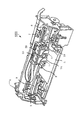
図2に、インクジェット式記録ヘッド1を示す分解部分斜視図を示した。インクジェット式記録ヘッド1の形状は略直方体であり、図2は、インクジェット式記録ヘッド1の長手方向(図中の白抜き矢印方向)に直交する面で切断した分解部分斜視図である。
図3(a)には、インクジェット式記録ヘッド1の部分平面図を、(b)には、そのA−A断面図を示した。
The
FIG. 2 is an exploded partial perspective view showing the ink
3A is a partial plan view of the ink
図2および図3において、インクジェット式記録ヘッド1は、第1の流路形成基板となる流路形成基板10と第2の流路形成基板となるノズルプレート20と接合基板30とコンプライアンス基板40と駆動IC200とを備えている。
流路形成基板10とノズルプレート20と接合基板30とは、流路形成基板10をノズルプレート20と接合基板30とで挟むように積み重ねられ、接合基板30上には、コンプライアンス基板40が形成されている。また、コンプライアンス基板40上には、駆動IC200が載せられている。
2 and 3, the ink
The flow
流路形成基板10は、面方位(110)のシリコン単結晶基板からなる。流路形成基板10には、複数の圧力発生室12が列をなすように形成されている。圧力発生室12のインクジェット式記録ヘッド1の長手方向に直交する断面形状は台形状で、圧力発生室12は、インクジェット式記録ヘッド1の幅方向に長く形成されている。
The flow
また、流路形成基板10の圧力発生室12の幅方向の一方端にはインク供給路13が形成され、インク供給路13と各圧力発生室12とが、各圧力発生室12毎に設けられた連通部14を介して連通されている。連通部14は、圧力発生室12よりも狭い幅で形成されており、連通部14から圧力発生室12に流入するインクの流路抵抗を一定に保持している。
圧力発生室12、連通部14およびインク供給路13等は、マスクを施したうえで、シリコン単結晶基板を異方性エッチング(ウェットエッチング)することによって得られる。具体的には、シリコン単結晶基板を、例えば、水酸化カリウム(KOH)水溶液等のエッチング液によってエッチングすることより、圧力発生室12、連通部14およびインク供給路13を同時に形成する。
In addition, an
The
流路形成基板10のノズルプレート20に対向する面と、圧力発生室12、インク供給路13および連通部14の側面には、第1の保護膜15が形成されている。第1の保護膜15は、低温で形成できるものが好ましく、例えば、CVDによって形成された酸化タンタル膜等が挙げられる。酸化タンタルのほか、Zr、窒化ケイ素膜等を用いることができる。
A first
ノズルプレート20には、各圧力発生室12のインク供給路13とは反対側の端部近傍に連通するノズル開口21が穿設されている。
なお、ノズルプレート20は、厚さが例えば、0.01〜1mmで、線膨張係数が300℃以下で、例えば2.5〜4.5[×10-6/℃]であるガラスセラミックス、シリコン単結晶基板または不錆鋼等からなる。ノズルプレート20の流路形成基板10に対向する面には、第2の保護膜22が形成されている。
The
The
流路形成基板10とノズルプレート20とは、第1の保護膜15および第2の保護膜22を介して、接着剤16によって接合されている。接着剤16としては、例えば、エポキシ系の接着剤を用いることができる。
第2の保護膜22は、その表面の接着剤16に対する接触角θ2が第1の保護膜15の表面の接着剤16に対する接触角θ1よりも小さいものを用いる。例えば、接着剤16がエポキシ系の接着剤の場合、第1の保護膜15である酸化タンタル膜に対して、第2の保護膜22として二酸化ケイ素膜を用いることができる。
ノズルプレート20にシリコン単結晶基板を用いたときには、熱酸化によってノズルプレート20の表面に、第2の保護膜22として二酸化ケイ素膜を形成することができる。
The flow
As the second
When a silicon single crystal substrate is used for the
流路形成基板10のノズルプレート20が接合された面と対向する面には、弾性膜50が形成されている。弾性膜50は、熱酸化により形成された二酸化ケイ素膜からなる。
また、流路形成基板10の弾性膜50上には、酸化膜からなる絶縁体膜51が形成されている。具体的には、弾性膜50上に、例えば、スパッタ法等によりジルコニウム層を形成後、このジルコニウム層を、例えば、500〜1200℃の拡散炉で熱酸化することにより酸化ジルコニウムからなる絶縁体膜51を形成する。
さらに、この絶縁体膜51上には、下電極60と、ペロブスカイト構造の圧電体層70と、上電極80とが形成され、圧力発生素子としての圧電素子300を構成している。ここで、圧電素子300は、下電極60、圧電体層70および上電極80を含む部分をいう。
An
An
Furthermore, a
圧電素子300は、具体的には、以下のように形成する。
下電極60を、白金等の金属やルテニウム酸ストロンチウム等の金属酸化物を絶縁体膜51上に積層することにより形成する。
例えば、まず、イリジウム等を含む層を形成し、次いで白金等を含む層を形成し、さらにイリジウム等を含む層を形成する。下電極60を構成する各層は、それぞれイリジウムまたは白金を絶縁体膜51の表面にスパッタ法等で付着させて形成する。その後、この下電極60を所定形状にパターニングする。
Specifically, the
The
For example, first, a layer containing iridium or the like is formed, then a layer containing platinum or the like is formed, and a layer containing iridium or the like is further formed. Each layer constituting the
次に、チタン酸ジルコン酸鉛(PZT)等からなる圧電体層70と、例えば、Au、Ir等の金属からなる上電極80とを形成する。その後、圧電体層70および上電極80をパターニングする。
なお、圧電素子300を構成する圧電体層70の材料としては、例えば、チタン酸ジルコン酸鉛(PZT)等の強誘電性圧電性材料や、これにニオブ、ニッケル、マグネシウム、ビスマス又はイットリウム等の金属を添加したリラクサ強誘電体等が用いられる。その組成は、圧電素子300の特性、用途等を考慮して適宜選択すればよいが、例えば、PbTiO3(PT)、PbZrO3(PZ)、Pb(ZrxTi1-x)O3(PZT)、Pb(Mg1/3Nb2/3)O3−PbTiO3(PMN−PT)、Pb(Zn1/3Nb2/3)O3−PbTiO3(PZN−PT)、Pb(Ni1/3Nb2/3)O3−PbTiO3(PNN−PT)、Pb(In1/2Nb1/2)O3−PbTiO3(PIN−PT)、Pb(Sc1/2Ta1/2)O3−PbTiO3(PST−PT)、Pb(Sc1/2Nb1/2)O3−PbTiO3(PSN−PT)、BiScO3−PbTiO3(BS−PT)、BiYbO3−PbTiO3(BY−PT)等が挙げられる。
Next, a
The material of the
また、圧電体層70の形成方法は、特に限定されないが、例えば、本実施形態では、金属有機物を触媒に溶解・分散した、いわゆるゾルを塗布乾燥してゲル化し、さらに高温で焼成することで金属酸化物からなる圧電体層70を得る、いわゆるゾル−ゲル法を用いて圧電体層70を形成することができる。
In addition, the method for forming the
一般的には、圧電素子300のいずれか一方の電極を共通電極とし、他方の電極および圧電体層70を各圧力発生室12毎にパターニングして構成する。そして、ここではパターニングされたいずれか一方の電極および圧電体層70から構成され、両電極への電圧の印加により圧電歪みが生じる部分を圧電体能動部という。
なお、本実施形態では、下電極60は圧電素子300の共通電極とし、上電極80を圧電素子300の個別電極としているが、駆動回路や配線の都合でこれを逆にしても支障はない。いずれの場合においても、各圧力発生室12毎に圧電体能動部が形成されていることになる。また、ここでは、圧電素子300と当該圧電素子300の駆動により変位が生じる弾性膜50および絶縁体膜51(2膜合わせて振動板53という)とを合わせてアクチュエータと称する。ここで、絶縁体膜51は、振動板53の一部として必ずしも形成されている必要はない。
In general, one electrode of the
In this embodiment, the
図2および図3において、このような各圧電素子300を構成する上電極80には、上電極用リード電極90が接続されている。
また、圧電素子300が形成された流路形成基板10上には、圧電素子300を駆動するための駆動IC200が実装される接合基板30が接着剤35によって接合されている。
接合基板30は、圧電素子300に対向する領域に、圧電素子300の運動を阻害しない程度の空間を確保した状態で、その空間を密封可能な圧電素子保持部32を有する。圧電素子保持部32は、圧力発生室12の列に対応して設けられている。
2 and 3, an upper
In addition, a
The
なお、本実施形態では、圧電素子保持部32は、圧力発生室12の列に対応する領域に一体的に設けられているが、圧電素子300毎に独立して設けられていてもよい。
接合基板30の材料としては、例えば、ガラス、セラミックス材料、金属、樹脂等が挙げられるが、流路形成基板10の熱膨張率と略同一の材料で形成されていることがより好ましく、本実施形態では、流路形成基板10と同一材料のシリコン単結晶基板を用いて形成する。
In the present embodiment, the piezoelectric
Examples of the material of the
また、接合基板30には、流路形成基板10のインク供給路13に対応する領域にリザーバ部31が設けられている。このリザーバ部31は、接合基板30を厚さ方向に圧力発生室12の列に沿って設けられており、流路形成基板10のインク供給路13と貫通孔52によって連通されて各圧力発生室12の共通のインク室となるリザーバ100を構成している。
In addition, the
また、接合基板30上には、図示しない外部配線が接続されて駆動信号が供給される配線パターンが設けられている。そして、配線パターン上に、各圧電素子300を駆動するための半導体集積回路(IC)である駆動IC200が実装されている。
In addition, on the
駆動信号は、例えば、駆動電源信号等の駆動ICを駆動させるための駆動系信号のほか、シリアル信号(SI)等の各種制御系信号を含み、配線パターンは、それぞれの信号が供給される複数の配線で構成される。 The drive signal includes, for example, a drive system signal for driving the drive IC such as a drive power supply signal, and various control system signals such as a serial signal (SI), and the wiring pattern includes a plurality of signals supplied with the respective signals. Consists of wiring.
下電極60は、圧力発生室12の長手方向では圧力発生室12に対向する領域内に形成され、複数の圧力発生室12に対応する領域に連続的に設けられている。また、下電極60は、圧力発生室12の列の外側まで延設されている。
The
上電極80の一端部近傍には上電極用リード電極90が接続されている。そして、駆動IC200と各圧電素子300から延設された上電極用リード電極90とは、例えば、ボンディングワイヤ等の導電性ワイヤからなる接続配線220によってそれぞれ電気的に接続されている。また、同様に、駆動IC200と下電極60とは、図示しない接続配線によって電気的に接続されている。
An upper
さらに、接合基板30上には、封止膜41および固定板42とからなるコンプライアンス基板40が接合されている。ここで、封止膜41は、剛性が低く可撓性を有する材料(例えば、厚さが6μmのポリフェニレンサルファイド(PPS)フィルム)からなり、この封止膜41によってリザーバ部31の一方面が封止されている。また、固定板42は、金属等の硬質の材料(例えば、厚さが30μmのステンレス鋼(SUS)等)で形成される。この固定板42のリザーバ100に対向する領域は、厚さ方向に完全に除去された開口部43となっているため、リザーバ100の一方面は可撓性を有する封止膜41のみである。
Further, a
インクジェット式記録ヘッド1の製造方法としては、例えば、ウェハ状態で複数のインクジェット式記録ヘッド1を形成した後に各インクジェット式記録ヘッド1を切り離すことによって得られる。
As a manufacturing method of the ink
このような本実施形態によれば、以下の効果がある。
(1)圧力発生室12およびインク供給路13、連通部14の内面には第1の保護膜15が形成され、ノズルプレート20の流路形成基板10に対向する面には第2の保護膜22が形成されているのでインクによる腐食が防げ、インクの噴射特性が安定したインクジェット式記録ヘッド1を得ることができる。さらに、接着剤16によって流路形成基板10とノズルプレート20とを接合する際に、第1の保護膜15の硬化前の接着剤16に対する接触角θ1が第2の保護膜22の硬化前の接着剤16に対する接触角θ2よりも大きいので、硬化前の接着剤16は親和性のよい第2の保護膜22に沿って流れ、圧力発生室12およびインク供給路13、連通部14に流れにくくできる。したがって、圧力発生室12の振動板53への接着剤16の付着が抑えられ、振動板53の変位特性の低下およびばらつきの少ないインクジェット式記録ヘッド1およびインクジェット式記録装置1000を得ることができる。
According to this embodiment, there are the following effects.
(1) A first
(2)エポキシ系接着剤の酸化タンタルに対する接触角θ1は酸化ケイ素に対する接触角θ2より大きく、酸化タンタルおよび酸化ケイ素は、インクに対する耐腐食性が高い。また、酸化タンタルは、低温での膜の形成が可能なので流路形成基板10にすでに形成された振動板53等への熱の影響を少なくできる。したがって、よりインクの噴射特性が安定し、振動板53の変位特性の低下およびばらつきの少ないインクジェット式記録ヘッド1およびインクジェット式記録装置1000を得ることができる。
(2) The contact angle θ1 of the epoxy adhesive with respect to tantalum oxide is larger than the contact angle θ2 with respect to silicon oxide, and tantalum oxide and silicon oxide have high corrosion resistance against ink. Further, since tantalum oxide can form a film at a low temperature, the influence of heat on the
(3)流路形成基板10およびノズルプレート20が同じシリコンなので、熱膨張差による歪みやそりの発生を少なくできる。また、酸化タンタルおよび酸化ケイ素はシリコンとの密着性を確保できる組み合わせともなる。
(3) Since the flow
(第2実施形態)
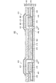
図4は、液体噴射ヘッドとしてのヘッドユニット400の部分断面図である。ヘッドユニット400も液体噴射装置としてのインクジェット式記録装置に用いられる。
ヘッドユニット400は、流路ユニット410とノズルプレート420とアクチュエータ430とを重ね合わせた状態で一体化して構成されている。図4では、アクチュエータ430を含む部分の部分断面図を示している。
(Second Embodiment)
FIG. 4 is a partial cross-sectional view of a
The
アクチュエータ430は、圧力変動によりノズル開口421を介して内部の液体を噴射する圧力発生室412をヘッド走査方向に2つ備えている。また、この圧力発生室412に対応して配設され、供給される駆動信号により変形して圧力発生室412内の液体に圧力変動を生じさせる圧電振動子500をヘッド走査方向に2つ備えている。さらに、圧力発生室412と圧電振動子500はノズル列方向のノズルに対応して設けられている。したがって、アクチュエータ430は、ノズル列に沿ってノズル列方向に細長い形状を有し、1つのアクチュエータ430で1列のノズル列からの液体の噴射を行う。
The actuator 430 includes two
アクチュエータ430は、圧力発生室412となる開口部を開設した流路形成基板としての圧力室プレート423、圧電振動子500が複数横並びに実装されるとともに、圧力発生室412の一部を区画する振動子プレート424と、供給側連通口461およびノズル連通口437となる開口部462を形成した流路形成基板としての連通口プレート426とを積層して構成されている。これらの圧力室プレート423、振動子プレート424および連通口プレート426は、金属から作成されており、各プレートは接着剤で接合されている。
The actuator 430 is mounted with a plurality of pressure chamber plates 423 and
圧力発生室412は、ノズル列とは直交する方向に細長い空部となっており、ノズル開口421に対応して複数形成されている。そして、各圧力発生室412の一端側は、供給側連通口461およびインク供給口436を通じてリザーバ438に連通している。また、供給側連通口461およびインク供給口436とは反対側の圧力発生室412の他端側は、ノズル連通口437を通じてノズル開口421に連通している。この圧力発生室412の一部は、振動子プレート424によって区画されている。
The
本実施形態において、圧電振動子500は、圧力発生素子の一種として機能する圧電振動子500に付与された電界に応じて撓み振動を行う、いわゆる撓みモードの圧電振動子である。
圧電振動子500は、駆動電極480と共通電極460と圧電体層470とを備えている。圧電体層470は、駆動電極480と共通電極460とに挟まれている。
圧電振動子500は、圧力発生室412とは反対側の振動子プレート424の表面に、圧力発生室412を覆い隠す状態に形成されている。すなわち、各圧電振動子500は、各圧力発生室412に対応してノズル列方向に列設されている。ここで、圧電振動子列の端部に位置するものは、インク滴の噴射に関与しない。つまり、駆動信号が供給されず駆動しないダミー振動子となっている。
In the present embodiment, the
The
The
流路ユニット410は、複数の流路形成基板からなり、オリフィスとして機能するインク供給口436およびノズル連通口437の一部となる供給口プレート用開口部が形成された流路形成基板としての供給口プレート431と、インクが供給されるリザーバ438(共通液体室)およびノズル連通口437の一部となるリザーバプレート用開口部が形成された流路形成基板としてのリザーバプレート433とを備えている。
The
リザーバプレート433の一方の面にノズルプレート420が、他方の面に供給口プレート431がそれぞれ配置されている。これらの部材の間は、図示しない接着剤で接合されている。この流路ユニット410は、リザーバ438からノズル開口421に至るまでのインク流路であるノズル連通口437を形成している。
The
ノズル連通口437の内面、リザーバ438の内面およびノズルプレート420に対向する面には、第1の保護膜415が設けられている。また、ノズルプレート420の流路形成ユニットに対向する面には、第2の保護膜422が形成されている。第1の保護膜415および第2の保護膜422は、第1実施形態における第1の保護膜15および第2の保護膜22と同様の材料および製法で形成することができる。
また、本実施形態では、第2の保護膜422は、ノズル開口421の内面にも形成されている。
流路ユニット410とノズルプレート420とは、接着剤416によって接合されている。
A first
In the present embodiment, the second
The
本実施形態によれば、以下の効果がある。
(4)複数の流路形成基板として、圧力室プレート423、連通口プレート426、供給口プレート431、リザーバプレート433を備えたヘッドユニット400においても、前述と同様の効果を得ることができる。
According to this embodiment, there are the following effects.
(4) The
以上述べた実施形態以外にも、種々の変更を行うことが可能である。
例えば、上述の実施形態において、第1の保護膜15および第1の保護膜415は、振動板53および振動子プレート424にも設けられていてもよい。
In addition to the embodiments described above, various modifications can be made.
For example, in the above-described embodiment, the first
また、上述した実施形態では、圧電素子300が接合基板30の圧電素子保持部32内に形成されているが、これに限定されず、勿論、圧電素子300は露出されていてもよい。
In the above-described embodiment, the
また、上述した実施形態においては、液体噴射ヘッドの一例としてインクジェット式記録ヘッドを説明したが、液体噴射ヘッドの基本的構成は上述したものに限定されるものではない。広く液体噴射ヘッドの全般を対象としたものであり、インク以外の液体を噴射するものにも勿論適用することができる。その他の液体噴射ヘッドとしては、例えば、プリンタ等の画像記録装置に用いられる各種の記録へッド、液晶ディスプレー等のカラーフィルタの製造に用いられる色材噴射ヘッド、有機ELディスプレー、FED(面発光ディスプレー)等の電極形成に用いられる電極材料噴射ヘッド、バイオchip製造に用いられる生体有機物噴射ヘッド等が挙げられる。 In the above-described embodiment, the ink jet recording head has been described as an example of the liquid ejecting head. However, the basic configuration of the liquid ejecting head is not limited to the above. The present invention is widely applicable to all liquid ejecting heads, and can naturally be applied to those ejecting liquids other than ink. Other liquid ejecting heads include, for example, various recording heads used in image recording apparatuses such as printers, color material ejecting heads used in the manufacture of color filters such as liquid crystal displays, organic EL displays, and FEDs (surface emitting devices). Examples thereof include an electrode material ejection head used for electrode formation such as a display, and a bioorganic matter ejection head used for biochip production.
1…液体噴射ヘッドとしてのインクジェット式記録ヘッド、10…流路形成基板、423…流路形成基板としての圧力室プレート、426…流路形成基板としての連通口プレート、431…流路形成基板としての供給口プレート、433…流路形成基板としてのリザーバプレート、12,412…圧力発生室、14,436,437,438,461…液体流路、15,415…第1の保護膜、16,416…接着剤、20,420…ノズルプレート、21,421…ノズル開口、22,422…第2の保護膜、53,424…振動板、300…圧力発生素子としての圧電素子、500…圧力発生素子としての圧電振動子、1000…液体噴射装置としてのインクジェット式記録装置。
DESCRIPTION OF
Claims (4)
一部が振動板で構成されている圧力発生室および前記液体の流路が形成された第1の流路形成基板と、
前記第1の流路形成基板の前記振動板とは反対側の面に接合された第2の流路形成基板と、
前記振動板を備え、前記圧力発生室内に圧力を加え、前記液体を前記ノズル開口から噴射させるアクチュエータと、
前記第1の流路形成基板の前記圧力発生室および前記流路の内面に形成された耐液体性を有する第1の保護膜と、
前記第2の流路形成基板の少なくとも前記第1の流路形成基板に接合する面に形成された耐液体性を有する第2の保護膜と、
を備え、
前記第1の流路形成基板と前記第2の流路形成基板とは、前記第1の保護膜と前記第2の保護膜との間に設けられた接着剤によって接着され、
前記第1の保護膜の表面における硬化前の前記接着剤に対する接触角θ1が、前記第2の保護膜の表面における硬化前の前記接着剤に対する接触角θ2より大きい
ことを特徴とする液体噴射ヘッド。 A liquid ejecting head for ejecting liquid from a nozzle opening,
A first flow path forming substrate in which a pressure generating chamber partially formed of a diaphragm and the liquid flow path are formed;
A second flow path forming substrate joined to a surface of the first flow path forming substrate opposite to the diaphragm;
An actuator comprising the diaphragm, applying pressure to the pressure generating chamber, and ejecting the liquid from the nozzle opening;
A first protective film having liquid resistance formed on the pressure generation chamber of the first flow path forming substrate and the inner surface of the flow path ;
A second protective film having liquid resistance formed on at least a surface of the second flow path forming substrate bonded to the first flow path forming substrate ;
With
The first flow path forming substrate and the second flow path forming substrate are bonded by an adhesive provided between the first protective film and the second protective film,
The liquid ejecting head, wherein a contact angle θ1 with respect to the adhesive before curing on the surface of the first protective film is larger than a contact angle θ2 with respect to the adhesive before curing on the surface of the second protective film. .
前記接着剤はエポキシ系接着剤であり、
前記第1の保護膜は酸化タンタルであり、
前記第2の保護膜は酸化ケイ素であることを特徴とする液体噴射ヘッド。 The liquid ejecting head according to claim 1,
The adhesive is an epoxy adhesive,
Wherein the first protective layer is tantalum oxide,
The second protective film liquid-jet head, wherein the silicon oxide der Turkey.
前記第1の流路形成基板および前記第2の流路形成基板は、シリコンからなることを特徴とする液体噴射ヘッド。 The liquid ejecting head according to claim 1, wherein
The first flow path forming substrate and the second flow path forming substrate is a liquid-jet head, wherein the silicon Tona Turkey.
Priority Applications (2)
| Application Number | Priority Date | Filing Date | Title |
|---|---|---|---|
| JP2008133950A JP5115330B2 (en) | 2008-05-22 | 2008-05-22 | Liquid ejecting head and liquid ejecting apparatus including the same |
| US12/471,184 US20090289999A1 (en) | 2008-05-22 | 2009-05-22 | Liquid ejecting head and liquid ejecting apparatus including the same |
Applications Claiming Priority (1)
| Application Number | Priority Date | Filing Date | Title |
|---|---|---|---|
| JP2008133950A JP5115330B2 (en) | 2008-05-22 | 2008-05-22 | Liquid ejecting head and liquid ejecting apparatus including the same |
Publications (3)
| Publication Number | Publication Date |
|---|---|
| JP2009279830A JP2009279830A (en) | 2009-12-03 |
| JP2009279830A5 JP2009279830A5 (en) | 2011-05-26 |
| JP5115330B2 true JP5115330B2 (en) | 2013-01-09 |
Family
ID=41341793
Family Applications (1)
| Application Number | Title | Priority Date | Filing Date |
|---|---|---|---|
| JP2008133950A Active JP5115330B2 (en) | 2008-05-22 | 2008-05-22 | Liquid ejecting head and liquid ejecting apparatus including the same |
Country Status (2)
| Country | Link |
|---|---|
| US (1) | US20090289999A1 (en) |
| JP (1) | JP5115330B2 (en) |
Families Citing this family (13)
| Publication number | Priority date | Publication date | Assignee | Title |
|---|---|---|---|---|
| JP5632643B2 (en) * | 2010-04-21 | 2014-11-26 | パナソニック株式会社 | Ferroelectric device |
| US9056986B2 (en) | 2010-11-09 | 2015-06-16 | Seiko Epson Corporation | Ultraviolet curable type ink-jet ink composition, recording method and recording apparatus using same |
| US8727508B2 (en) * | 2011-11-10 | 2014-05-20 | Xerox Corporation | Bonded silicon structure for high density print head |
| EP3205511B1 (en) | 2012-03-28 | 2020-12-09 | Seiko Epson Corporation | Ink jet recording method, and ink jet recording apparatus |
| JP6191120B2 (en) | 2012-03-29 | 2017-09-06 | セイコーエプソン株式会社 | Ink jet recording method and ink jet recording apparatus |
| US10029483B2 (en) | 2012-04-25 | 2018-07-24 | Seiko Epson Corporation | Ink jet recording method, ultraviolet-ray curable ink, and ink jet recording apparatus |
| JP6236768B2 (en) | 2012-04-27 | 2017-11-29 | セイコーエプソン株式会社 | Ink jet recording method and ink jet recording apparatus |
| JP6065535B2 (en) | 2012-11-15 | 2017-01-25 | セイコーエプソン株式会社 | UV-curable ink composition for ink jet recording, ink container, and ink jet recording apparatus |
| JP6201313B2 (en) * | 2012-12-27 | 2017-09-27 | セイコーエプソン株式会社 | Liquid ejecting head and liquid ejecting apparatus |
| JP6318473B2 (en) | 2013-06-07 | 2018-05-09 | セイコーエプソン株式会社 | Inkjet recording method |
| JP6319625B2 (en) | 2014-03-27 | 2018-05-09 | セイコーエプソン株式会社 | Inkjet method and inkjet apparatus |
| JP6932519B2 (en) * | 2016-05-26 | 2021-09-08 | キヤノン株式会社 | Liquid discharge head, its manufacturing method, and recording method |
| JP7523987B2 (en) * | 2020-07-31 | 2024-07-29 | キヤノン株式会社 | Liquid ejection head and manufacturing method thereof |
Family Cites Families (5)
| Publication number | Priority date | Publication date | Assignee | Title |
|---|---|---|---|---|
| TW417025B (en) * | 1997-04-10 | 2001-01-01 | Sumitomo Chemical Co | Front plate for plasma display |
| JP2003320663A (en) * | 2002-05-02 | 2003-11-11 | Ricoh Co Ltd | Liquid drop ejection head and its manufacturing method, ink cartridge and ink jet recorder |
| JP3726909B2 (en) * | 2002-07-10 | 2005-12-14 | セイコーエプソン株式会社 | Method for manufacturing liquid jet head |
| JP2007050673A (en) * | 2005-08-19 | 2007-03-01 | Seiko Epson Corp | Method for manufacturing liquid jet head |
| JP2007112075A (en) * | 2005-10-24 | 2007-05-10 | Seiko Epson Corp | Electrostatic actuator, droplet discharge head, droplet discharge apparatus, and electrostatic device manufacturing method |
-
2008
- 2008-05-22 JP JP2008133950A patent/JP5115330B2/en active Active
-
2009
- 2009-05-22 US US12/471,184 patent/US20090289999A1/en not_active Abandoned
Also Published As
| Publication number | Publication date |
|---|---|
| US20090289999A1 (en) | 2009-11-26 |
| JP2009279830A (en) | 2009-12-03 |
Similar Documents
| Publication | Publication Date | Title |
|---|---|---|
| JP5115330B2 (en) | Liquid ejecting head and liquid ejecting apparatus including the same | |
| JP4258668B2 (en) | Liquid ejecting head and liquid ejecting apparatus | |
| JP4450238B2 (en) | Liquid ejecting head and liquid ejecting apparatus | |
| JP2009016625A (en) | Actuator, liquid ejecting head, and liquid ejecting apparatus | |
| CN101544113A (en) | Liquid ejecting head, liquid ejecting apparatus, and actuator | |
| JP2002046281A (en) | Ink jet recording head, method of manufacturing the same, and ink jet recording apparatus | |
| JP2009051104A (en) | Liquid ejecting head and liquid ejecting apparatus | |
| JP2001287363A (en) | Ink jet recording head and ink jet recording apparatus | |
| JP2010221434A (en) | Liquid ejecting head, manufacturing method thereof, and liquid ejecting apparatus | |
| JP2011224785A (en) | Method for manufacturing of liquid jet head | |
| JP2009255528A (en) | Liquid jetting head, piezoelectric element, and liquid jetting device | |
| JP5447786B2 (en) | Liquid ejecting head, liquid ejecting apparatus, and actuator device | |
| JP2009061729A (en) | Liquid ejecting head and liquid ejecting apparatus | |
| JP2006255972A (en) | Liquid ejecting head and liquid ejecting apparatus | |
| JP2010228272A (en) | Liquid ejecting head manufacturing method, liquid ejecting head, and liquid ejecting apparatus | |
| JP2010173197A (en) | Liquid discharge head, liquid discharge device, actuator device, and manufacturing method of liquid discharge head | |
| JP2009255524A (en) | Liquid jetting head and liquid jetting device | |
| JP2006218716A (en) | Liquid ejecting head and liquid ejecting apparatus | |
| JP2006310746A (en) | Piezoelectric element, liquid ejecting head using the piezoelectric element, and liquid ejecting apparatus | |
| JP4475042B2 (en) | Method for manufacturing liquid jet head | |
| JP2012213957A (en) | Liquid injection head, and method of manufacturing the same | |
| JP5690476B2 (en) | Liquid ejecting head manufacturing method, liquid ejecting head, and liquid ejecting apparatus | |
| JP5670017B2 (en) | Liquid ejecting head, liquid ejecting apparatus, and actuator device | |
| JP5256998B2 (en) | Method for manufacturing actuator device and method for manufacturing liquid jet head | |
| JP2012218232A (en) | Manufacturing method of liquid jet head |
Legal Events
| Date | Code | Title | Description |
|---|---|---|---|
| A521 | Written amendment |
Free format text: JAPANESE INTERMEDIATE CODE: A523 Effective date: 20110412 |
|
| A621 | Written request for application examination |
Free format text: JAPANESE INTERMEDIATE CODE: A621 Effective date: 20110412 |
|
| A977 | Report on retrieval |
Free format text: JAPANESE INTERMEDIATE CODE: A971007 Effective date: 20120907 |
|
| TRDD | Decision of grant or rejection written | ||
| A01 | Written decision to grant a patent or to grant a registration (utility model) |
Free format text: JAPANESE INTERMEDIATE CODE: A01 Effective date: 20120918 |
|
| A01 | Written decision to grant a patent or to grant a registration (utility model) |
Free format text: JAPANESE INTERMEDIATE CODE: A01 |
|
| A61 | First payment of annual fees (during grant procedure) |
Free format text: JAPANESE INTERMEDIATE CODE: A61 Effective date: 20121001 |
|
| R150 | Certificate of patent or registration of utility model |
Free format text: JAPANESE INTERMEDIATE CODE: R150 Ref document number: 5115330 Country of ref document: JP Free format text: JAPANESE INTERMEDIATE CODE: R150 |
|
| FPAY | Renewal fee payment (event date is renewal date of database) |
Free format text: PAYMENT UNTIL: 20151026 Year of fee payment: 3 |
|
| S531 | Written request for registration of change of domicile |
Free format text: JAPANESE INTERMEDIATE CODE: R313531 |
|
| R350 | Written notification of registration of transfer |
Free format text: JAPANESE INTERMEDIATE CODE: R350 |