JP7561558B2 - System for estimating strength development amount of cement-water mixture, method for estimating strength development amount of cement-water mixture, and sensor for estimating strength development amount of cement-water mixture - Google Patents
System for estimating strength development amount of cement-water mixture, method for estimating strength development amount of cement-water mixture, and sensor for estimating strength development amount of cement-water mixture Download PDFInfo
- Publication number
- JP7561558B2 JP7561558B2 JP2020162941A JP2020162941A JP7561558B2 JP 7561558 B2 JP7561558 B2 JP 7561558B2 JP 2020162941 A JP2020162941 A JP 2020162941A JP 2020162941 A JP2020162941 A JP 2020162941A JP 7561558 B2 JP7561558 B2 JP 7561558B2
- Authority
- JP
- Japan
- Prior art keywords
- cement
- water mixture
- tag
- reader
- radio wave
- Prior art date
- Legal status (The legal status is an assumption and is not a legal conclusion. Google has not performed a legal analysis and makes no representation as to the accuracy of the status listed.)
- Active
Links
- XLYOFNOQVPJJNP-UHFFFAOYSA-N water Substances O XLYOFNOQVPJJNP-UHFFFAOYSA-N 0.000 title claims description 303
- 239000000203 mixture Substances 0.000 title claims description 241
- 238000011161 development Methods 0.000 title claims description 64
- 238000000034 method Methods 0.000 title claims description 55
- 239000004568 cement Substances 0.000 claims description 68
- 239000004567 concrete Substances 0.000 claims description 37
- 239000004570 mortar (masonry) Substances 0.000 claims description 31
- 125000006850 spacer group Chemical group 0.000 claims description 27
- 238000010521 absorption reaction Methods 0.000 claims description 25
- 230000001012 protector Effects 0.000 claims description 17
- 238000005266 casting Methods 0.000 claims description 15
- 239000000463 material Substances 0.000 claims description 15
- 230000018109 developmental process Effects 0.000 description 43
- 238000004891 communication Methods 0.000 description 31
- 238000010586 diagram Methods 0.000 description 20
- 230000035515 penetration Effects 0.000 description 17
- 230000000875 corresponding effect Effects 0.000 description 16
- 238000012545 processing Methods 0.000 description 16
- 230000006870 function Effects 0.000 description 14
- 238000000926 separation method Methods 0.000 description 13
- 238000012360 testing method Methods 0.000 description 12
- 238000006703 hydration reaction Methods 0.000 description 7
- 238000010276 construction Methods 0.000 description 6
- 238000005259 measurement Methods 0.000 description 5
- 238000009933 burial Methods 0.000 description 4
- 230000007423 decrease Effects 0.000 description 4
- -1 polyethylene Polymers 0.000 description 4
- 229910000831 Steel Inorganic materials 0.000 description 3
- 238000009415 formwork Methods 0.000 description 3
- 239000002184 metal Substances 0.000 description 3
- 229910052751 metal Inorganic materials 0.000 description 3
- 239000010959 steel Substances 0.000 description 3
- 239000004698 Polyethylene Substances 0.000 description 2
- 239000004743 Polypropylene Substances 0.000 description 2
- 239000004676 acrylonitrile butadiene styrene Substances 0.000 description 2
- 239000000919 ceramic Substances 0.000 description 2
- 230000001419 dependent effect Effects 0.000 description 2
- 238000011156 evaluation Methods 0.000 description 2
- 239000011372 high-strength concrete Substances 0.000 description 2
- 150000002739 metals Chemical class 0.000 description 2
- 229920000573 polyethylene Polymers 0.000 description 2
- 229920001155 polypropylene Polymers 0.000 description 2
- 239000011347 resin Substances 0.000 description 2
- 229920005989 resin Polymers 0.000 description 2
- 230000005236 sound signal Effects 0.000 description 2
- 230000005540 biological transmission Effects 0.000 description 1
- 230000000052 comparative effect Effects 0.000 description 1
- 230000002596 correlated effect Effects 0.000 description 1
- 238000005516 engineering process Methods 0.000 description 1
- 230000012447 hatching Effects 0.000 description 1
- 230000006698 induction Effects 0.000 description 1
- 239000007769 metal material Substances 0.000 description 1
- 238000007589 penetration resistance test Methods 0.000 description 1
- 230000000704 physical effect Effects 0.000 description 1
- 239000011513 prestressed concrete Substances 0.000 description 1
- 230000002250 progressing effect Effects 0.000 description 1
- 230000003014 reinforcing effect Effects 0.000 description 1
Images


Landscapes
- On-Site Construction Work That Accompanies The Preparation And Application Of Concrete (AREA)
Description
本発明は、セメント水混練体の強度発現量を推定するためのシステム及び方法に関する。また、本発明は、このような推定処理に利用可能なセンサに関する。 The present invention relates to a system and method for estimating the strength development of a cement-water mixture. The present invention also relates to a sensor that can be used for such estimation processing.
施工段階において、コンクリートやモルタル中の強度発現を予測することは、耐久性の効率的な管理の観点から重要である。 Predicting the strength development in concrete and mortar during the construction stage is important from the perspective of efficient durability management.
例えば、床コンクリートの施工段階では、フレッシュコンクリートを打設した後、凝結が進行して一定程度の強度が発現した後に仕上げ作業が行われる。また、コンクリート構造物の施工段階では、一定程度の強度が発現した段階で型枠を外す作業(脱型)が行われる。更に、コンクリートにPC鋼材を導入してプレストレストコンクリートを作製する際にも、所定の強度が発現したタイミングでプレストレス力を導入する作業が行われる。具体的には、ポストテンション方式の場合には、所定の強度が発現したタイミングでPC鋼材に緊張力を与え、逆に、プレテンション方式の場合には、事前に緊張力を与えたPC鋼材を導入した後に、所定の強度が発現したタイミングで緊張力を解放する。 For example, in the construction stage of floor concrete, after fresh concrete is poured, finishing work is carried out after the concrete has set and a certain level of strength has been achieved. Also, in the construction stage of concrete structures, the formwork is removed (removal of the formwork) when a certain level of strength has been achieved. Furthermore, when PC steel is introduced into the concrete to produce prestressed concrete, the prestressing force is introduced when a certain level of strength has been achieved. Specifically, in the case of the post-tensioning method, tension is applied to the PC steel when a certain level of strength has been achieved, and conversely, in the case of the pretensioning method, tension is released when a certain level of strength has been achieved after pre-tensioned PC steel is introduced.
しかし、従来、フレッシュコンクリートに対する硬化が進行して所定の強度に達したか否か、すなわち、例えば表面の仕上げ時期の判定は、施工者の感覚によるところが大きく、施工者の習熟度によって判断の時期にバラつきが生じるという課題があった。他にも、型枠を脱型する時期に関しては、別途、フレッシュコンクリートから供試体を採取し、供試体による強度試験を実施し確認する方法等、手間のかかる課題がある。そのため、施工者の習熟度に依存せずに作業時期の判断を適切に行い、コンクリートの強度発現状態を効率的に管理できる技術が求められている。 However, in the past, the determination of whether or not fresh concrete has hardened to a certain strength, i.e., for example, when to finish the surface, was largely dependent on the builder's sense, and there was an issue that the timing of the judgment varied depending on the builder's level of skill. In addition, there was a time-consuming issue with determining when to remove the formwork, such as a separate method of taking test specimens from the fresh concrete and conducting strength tests on the test specimens. Therefore, there is a demand for technology that can appropriately determine the timing of work without relying on the builder's level of skill, and efficiently manage the state of concrete strength development.
なお、従来、施工時間帯の予想気温を「見なしコンクリート温度」とし、予め把握された、貫入抵抗値と経過時間の関係を表す近似式の傾き情報とコンクリートの温度との関係に、前記見なしコンクリート温度の情報を当てはめることで、仕上げ作業の時期を予想する方法が開示されている(特許文献1参照)。 In addition, a method has been disclosed in which the expected temperature during the construction period is taken as the "deemed concrete temperature," and the timing of finishing work is predicted by applying information about the deemed concrete temperature to the relationship between the concrete temperature and the slope information of an approximation equation that represents the relationship between the penetration resistance value and the elapsed time, which is known in advance (see Patent Document 1).
コンクリートの硬化具合を把握する方法としては、JIS A 1147に規定された貫入抵抗試験が知られている。この方法は、供試体としてのモルタルに対して、規定の貫入針を垂直に刺した際の貫入抵抗値によって硬化の程度を検知する方法である。経時的に複数の時点で貫入抵抗値を測定することで、コンクリートの始発時間(貫入抵抗値が例えば3.5N/mm2になるまでの時間)、及び終結時間(貫入抵抗値が例えば28.0N/mm2になるまでの時間)と、これらプロットの近似曲線から、貫入抵抗値と経過時間との関係式が得られる。 A known method for grasping the degree of hardening of concrete is the penetration resistance test specified in JIS A 1147. This method is a method for detecting the degree of hardening by the penetration resistance value when a specified penetration needle is inserted vertically into a mortar specimen. By measuring the penetration resistance value at multiple points in time, the initial setting time of the concrete (the time until the penetration resistance value reaches, for example, 3.5 N/ mm2 ) and the final setting time (the time until the penetration resistance value reaches, for example, 28.0 N/ mm2 ) and the approximation curve of the plot of these can be used to obtain a relationship between the penetration resistance value and the elapsed time.
しかし、この方法によって硬化の程度(強度発現量)を検知するためには、検知の際に別途の供試体を用いて計測する必要があるところ、作業が煩雑化するおそれがある。 However, in order to detect the degree of hardening (amount of strength developed) using this method, it is necessary to measure using a separate test specimen, which can make the work more complicated.
また、特許文献1に記載された方法は、あくまで気温の変化の予想に基づいて硬化の程度を予想するというものであり、各現場ごとの環境に応じた強度予想ではないため、高い精度での推定が難しい。打設後のコンクリートの、強度変化の傾向を事前に予想する目的であれば、この程度の精度でも利用価値が見いだせるが、該当現場において、現時点におけるコンクリートやモルタルの強度発現量を知りたい場合には、精度面であまり有効な方法とはいえない。
Furthermore, the method described in
本発明は、上記の課題に鑑み、簡易な方法で精度良くセメント水混練体の強度発現量を推定できるシステム及び方法を提供することを目的とする。また、本発明は、このような方法の実施に利用可能な、セメント水混練体の強度発現量の推定用センサを提供することを別の目的とする。 In view of the above problems, the present invention aims to provide a system and method that can estimate the strength development amount of a cement-water mixture with high accuracy in a simple manner. Another aim of the present invention is to provide a sensor for estimating the strength development amount of a cement-water mixture that can be used to implement such a method.
本発明は、打設後のフレッシュコンクリート又は打設後のフレッシュモルタルに属するセメント水混練体の強度発現量の推定システムであって、
前記セメント水混練体に埋設されたRFタグと、
前記RFタグとの間で電波信号の送受信が可能なリーダ又はリーダライタと、
前記リーダ又はリーダライタで受信した前記電波信号の強度値、若しくは前記電波信号の受信が検知できる前記リーダ又はリーダライタと前記セメント水混練体との離間距離の上限閾値の少なくとも一方の指標値に基づいて、前記セメント水混練体の強度発現量を推定する推定装置とを備えたことを特徴とする。
The present invention provides a system for estimating the strength development amount of a cement-water mixture belonging to fresh concrete after casting or fresh mortar after casting,
An RF tag embedded in the cement-water mixture;
a reader or reader/writer capable of transmitting and receiving radio signals to and from the RF tag;
The present invention is characterized in that it is equipped with an estimation device that estimates the strength expression amount of the cement water mixture based on at least one of the index values of the intensity value of the radio wave signal received by the reader or reader/writer, or the upper threshold value of the distance between the reader or reader/writer that can detect reception of the radio wave signal and the cement water mixture.
本明細書において、「セメント水混練体」とは、セメントと水を少なくとも含む混練混合物を指す。 In this specification, "cement-water mixture" refers to a mixture that contains at least cement and water.
本明細書において、「リーダ」とは、RFタグから送信される電波信号を読み取る機能を備え、RFタグに対して情報の書き込み機能を備えない機器を指し、「リーダライタ」とは、RFタグから送信される電波信号を読み取る機能と共に、RFタグに対して情報の書き込み機能を備える機器を指す。以下では、煩雑さを避けるために、リーダ又はリーダライタという記載を、「リーダライタ等」と略記することがある。 In this specification, "reader" refers to a device that has the function of reading radio signals transmitted from RF tags, but does not have the function of writing information to RF tags, and "reader/writer" refers to a device that has the function of reading radio signals transmitted from RF tags, as well as the function of writing information to RF tags. In the following, to avoid complexity, the terms reader and reader/writer may be abbreviated to "reader/writer, etc."
本明細書において、「セメント水混練体の強度発現量」とは、セメント水混練体の凝結の程度を指標する物性値であり、JIS A 1147に準拠した方法で測定した貫入抵抗値とすることができる。この強度発現量は、所定の基準強度に対する相対的な強度を指す。この基準強度としては、完全に硬化された時点における強度としても構わないし、凝結過程における強度としても構わない。 In this specification, the "strength development of a cement-water mixture" is a physical property value that indicates the degree of setting of the cement-water mixture, and can be a penetration resistance value measured by a method conforming to JIS A 1147. This strength development refers to a strength relative to a predetermined reference strength. This reference strength may be the strength at the time when the mixture is completely hardened, or the strength during the setting process.
水は導電性であるため、電波を吸収する性質を示す。このため、セメント水混練体に埋設されたRFタグとセメント水混練体の表面との間に水分が存在すると、リーダライタ等とRFタグとの間における通信を妨害する。この妨害の程度は、水分量が多いほど高くなる。言い換えれば、セメント水混練体に含まれる水分量が多いほど、リーダライタ等で受信できる電波強度は小さくなる傾向を示す。また、リーダライタ等がRFタグからの電波信号が受信できるようになるまで、リーダライタ等とセメント水混練体の表面との間の離間距離を縮めていく場合には、セメント水混練体に含まれる水分量が多いほどその離間距離は狭くなる。 Water is conductive and therefore has the property of absorbing radio waves. For this reason, if there is moisture between the RF tag embedded in the cement-water mixture and the surface of the cement-water mixture, it will interfere with communication between the reader/writer and the RF tag. The degree of this interference increases with the amount of moisture. In other words, the more moisture there is in the cement-water mixture, the weaker the radio wave intensity that can be received by the reader/writer tends to be. In addition, when the distance between the reader/writer and the surface of the cement-water mixture is reduced until the reader/writer can receive radio signals from the RF tag, the greater the amount of moisture contained in the cement-water mixture, the narrower the distance will be.
硬化前のフレッシュコンクリート又はフレッシュモルタルは、時間が経過すると共に水和反応が進展して硬化が進行していくに連れ、自由水が減少する。このため、リーダライタ等で受信された電波強度の大きさが上昇してきたことを確認することで、セメント組成物に対する水和反応の進行の程度が認識でき、フレッシュコンクリート又はフレッシュモルタルの硬化の程度が確認できる。 In fresh concrete or fresh mortar before hardening, the amount of free water decreases as the hydration reaction progresses over time and hardening progresses. Therefore, by checking that the intensity of the radio waves received by a reader/writer or the like is increasing, the degree to which the hydration reaction in the cement composition has progressed can be recognized, and the degree of hardening of the fresh concrete or fresh mortar can be confirmed.
水和反応は、フレッシュコンクリート又はフレッシュモルタルの全体にわたってほぼ均一的に生じるため、リーダライタ等で受信された電波信号の強度値、若しくはリーダライタ等とセメント水混練体との離間距離の前記上限閾値によって、フレッシュコンクリート又はフレッシュモルタルの強度発現量を推定することが可能である。特に、予めフレッシュコンクリート又はフレッシュモルタルにRFタグを埋設しておけば、リーダライタ等をセメント水混練体に近づけて電波信号を受信することのみでセメント水混練体の強度発現量を推定できるため、極めて簡易な方法で強度発現量の推定が行える。 Since the hydration reaction occurs almost uniformly throughout the fresh concrete or fresh mortar, it is possible to estimate the strength development of the fresh concrete or fresh mortar from the intensity value of the radio signal received by a reader/writer or the upper threshold value of the distance between the reader/writer and the cement-water mixture. In particular, if an RF tag is embedded in the fresh concrete or fresh mortar in advance, the strength development of the cement-water mixture can be estimated simply by bringing the reader/writer close to the cement-water mixture and receiving the radio signal, making it possible to estimate the strength development in an extremely simple manner.
前記推定装置は、前記指標値を経時的に測定すると共に、前記指標値が増加傾向を示すことを検知すると前記セメント水混練体の強度発現量が増加したことを推定するものとしても構わない。 The estimation device may measure the index value over time and, upon detecting that the index value shows an increasing trend, estimate that the strength development amount of the cement-water mixture has increased.
また、前記推定装置は、前記指標値が所定の閾値に達した後、報知信号を出力する報知部を備えるものとしても構わない。これにより、作業員は、仕上げ作業時期、脱型時期、プレストレス力の導入時期等の到来タイミングを、個人の習熟度に関わらず容易に知ることができる。 The estimation device may also include an alarm unit that outputs an alarm signal after the index value reaches a predetermined threshold value. This allows workers to easily know the timing of finishing work, demolding, introduction of prestress force, etc., regardless of their individual level of proficiency.
前記推定装置は、リーダライタ等に搭載されているものとしても構わないし、リーダライタ等とは別体の装置として構成されていても構わない。前者の場合、推定装置は、入力された前記指標値に基づいて所定の演算処理を行うことで、セメント水混練体の強度発現量の推定を行うソフトウェア手段とすることができる。後者の場合には、リーダライタ等との間で通信可能であって、前記演算処理を行う機能を搭載したコンピュータや専用のハードウェア装置とすることができる。 The estimation device may be mounted on a reader/writer or the like, or may be configured as a device separate from the reader/writer. In the former case, the estimation device may be a software means that estimates the strength development amount of the cement-water mixture by performing a predetermined calculation process based on the input index value. In the latter case, the estimation device may be a computer or dedicated hardware device that is capable of communicating with the reader/writer and has a function for performing the calculation process.
前記システムは、前記指標値と前記セメント水混練体の強度発現量との相関関係に関する情報が記録された記憶部を備え、
前記推定装置は、前記記憶部から前記相関関係に関する情報を読み出して、測定された前記指標値に対応する前記セメント水混練体の強度発現量を推定するものとしても構わない。
The system includes a storage unit in which information regarding a correlation between the index value and a strength development amount of the cement-water mixture is recorded,
The estimation device may read out information regarding the correlation from the storage unit, and estimate the strength development amount of the cement-water mixture corresponding to the measured index value.
この記憶部は、例えば、リーダライタ等又はリーダライタ等と別体の装置内に搭載されたメモリによって構成できる。また、前記相関関係に関する情報としては、データテーブルの形式で記載されたものであっても構わないし、関数の形式で記載されたものであっても構わない。 This storage unit can be configured, for example, by a memory mounted in a reader/writer or a device separate from the reader/writer. The information regarding the correlation may be written in the form of a data table or a function.
前記RFタグは、前記セメント水混練体内における埋設深さの異なる第一RFタグ及び第二RFタグを含み、
前記推定装置は、前記第一RFタグからの前記電波信号の強度値に基づく前記指標値である第一指標値と、前記第二RFタグからの前記電波信号の強度値に基づく前記指標値である第二指標値との比較結果に基づいて、前記セメント水混練体の強度発現量を推定するものとしても構わない。
The RF tag includes a first RF tag and a second RF tag embedded at different depths in the cement-water mixture,
The estimation device may also be configured to estimate the strength expression amount of the cement-water mixture based on a comparison result between a first index value, which is an index value based on the intensity value of the radio wave signal from the first RF tag, and a second index value, which is an index value based on the intensity value of the radio wave signal from the second RF tag.
リーダライタ等で受信した電波信号の強度値によってセメント水混練体の強度発現量を推定する場合、推定精度を高めるためには、リーダライタ等とセメント水混練体の表面との離間距離を所定の値に設定するのが好ましい。しかしながら、現実的には推定処理の実行時にリーダライタ等の位置が変動することも予想される。 When estimating the strength expression of a cement-water mixture from the strength value of a radio wave signal received by a reader/writer or the like, it is preferable to set the distance between the reader/writer or the like and the surface of the cement-water mixture to a predetermined value in order to improve the estimation accuracy. However, in reality, it is expected that the position of the reader/writer or the like will fluctuate when the estimation process is performed.
これに対し、上記構成によれば、予めセメント水混練体内における埋設深さの異なる位置に、第一RFタグと第二RFタグとが埋設されている。このため、リーダライタ等とセメント水混練体の表面との離間距離が仮に変動したとしても、リーダライタ等と第一RFタグとの離間距離(第一離間距離)と、リーダライタ等と第二RFタグとの離間距離(第二離間距離)との差は、埋設深さ位置の差で固定される。よって、第一RFタグからの電波信号の強度値に基づく第一指標値と、第二RFタグからの電波信号の強度値に基づく第二指標値との比較結果(詳細な一例としては差分値)は、セメント水混練体内における、第一RFタグの埋設位置と第二RFタグの埋設位置の間の領域に存在する水分量の多寡に左右される。そして、この水分量の多寡は、セメント水混練体の強度発現量を投影する情報である。従って、前記比較結果に基づいてセメント水混練体の強度発現量を精度良く推定できる。 In contrast, according to the above configuration, the first RF tag and the second RF tag are embedded in advance at different embedded depths in the cement water mixer. Therefore, even if the distance between the reader/writer or the like and the surface of the cement water mixer fluctuates, the difference between the distance between the reader/writer or the like and the first RF tag (first distance) and the distance between the reader/writer or the like and the second RF tag (second distance) is fixed by the difference in embedded depth positions. Therefore, the comparison result (a detailed example is a difference value) between the first index value based on the intensity value of the radio wave signal from the first RF tag and the second index value based on the intensity value of the radio wave signal from the second RF tag depends on the amount of moisture present in the area between the embedded positions of the first RF tag and the second RF tag in the cement water mixer. This amount of moisture is information that projects the strength expression amount of the cement water mixer. Therefore, the strength expression amount of the cement water mixer can be accurately estimated based on the comparison result.
前記システムは、前記セメント水混練体内に埋設され、前記セメント水混練体よりも吸水率が低い材料からなるタグ保護体を有し、
前記RFタグは、前記タグ保護体内に埋設された第一RFタグと、前記タグ保護体の外側の位置において前記セメント水混練体内に埋設された第二RFタグとを含み、
前記推定装置は、前記第一RFタグからの前記電波信号の強度値に基づく前記指標値である第一指標値と、前記第二RFタグからの前記電波信号の強度値に基づく前記指標値である第二指標値との比較結果に基づいて、前記セメント水混練体の強度発現量を推定するものとしても構わない。
The system includes a tag protector that is embedded in the cement water mixture and is made of a material having a lower water absorption rate than the cement water mixture,
The RF tag includes a first RF tag embedded in the tag protector and a second RF tag embedded in the cement-water mixer at a position outside the tag protector,
The estimation device may also be configured to estimate the strength expression amount of the cement-water mixture based on a comparison result between a first index value, which is an index value based on the intensity value of the radio wave signal from the first RF tag, and a second index value, which is an index value based on the intensity value of the radio wave signal from the second RF tag.
このような構成によれば、前述したように、リーダライタ等で受信した電波信号の強度値によってセメント水混練体の強度発現量を推定する場合において、推定処理の実行時にリーダライタ等の位置が変動することは予想されるところ、予めセメント水混練体内において、吸水率が低い材料からなるタグ保護体内に埋設された第一RFタグと、その外側の領域に配置された第二RFタグとが埋設されている。 As described above, with this configuration, when estimating the strength expression amount of the cement water mixture from the strength value of the radio wave signal received by a reader/writer or the like, it is expected that the position of the reader/writer or the like will change when the estimation process is performed. Therefore, a first RF tag is embedded in a tag protector made of a material with low water absorption rate, and a second RF tag is placed in the outer area of the tag protector, which is embedded in the cement water mixture in advance.
このため、深さ方向に関して、セメント水混練体内において、第一RFタグとセメント水混練体の表面との間の領域に含まれる水分量と、第二RFタグとセメント水混練体の表面との間の領域に含まれる水分量には、タグ保護体の吸水率とセメント水混練体の吸水率の相違に基づく差が生じる。この結果、第一RFタグからの電波信号の強度値に基づく第一指標値と、第二RFタグからの電波信号の強度値に基づく第二指標値との比較結果は、セメント水混練体内における、第二RFタグの埋設位置とセメント水混練体表面との間の領域に存在する水分量の多寡に左右される。特に、第一RFタグと第二RFタグの両者を、ほぼ同じ埋設深さの位置に埋設しておくことで、第一指標値と第二指標値の比率が、セメント水混練体表面と第二RFタグの埋設位置との間の領域に存在する水分量の多寡を示す指標となるため、この値に基づいてセメント水混練体の強度発現量を精度良く推定できる。 Therefore, in the depth direction, a difference occurs between the amount of moisture contained in the region between the first RF tag and the surface of the cement water mix and the amount of moisture contained in the region between the second RF tag and the surface of the cement water mix, based on the difference between the water absorption rate of the tag protector and the water absorption rate of the cement water mix. As a result, the comparison result between the first index value based on the intensity value of the radio wave signal from the first RF tag and the second index value based on the intensity value of the radio wave signal from the second RF tag depends on the amount of moisture present in the region between the buried position of the second RF tag and the surface of the cement water mix. In particular, by burying both the first RF tag and the second RF tag at approximately the same buried depth, the ratio of the first index value to the second index value becomes an index showing the amount of moisture present in the region between the surface of the cement water mix and the buried position of the second RF tag, and the strength development amount of the cement water mix can be accurately estimated based on this value.
第一RFタグと第二RFタグの両者の埋設深さを同じにするためには、例えば、第二RFタグを予めセメント水混練体と同一の材料からなる硬化コンクリート又は硬化モルタル内に埋設してなるタグ埋設物を準備しておくと共に、第一RFタグが埋設されたタグ保護体と、第二RFタグが埋設されたタグ埋設物とを、共にセメント水混練体内に埋設する方法が採用できる。 In order to embed the first and second RF tags to the same depth, for example, a method can be used in which the second RF tag is embedded in hardened concrete or hardened mortar made of the same material as the cement-water mixture to prepare a tag embedding object, and then both the tag protection body with the first RF tag embedded in it and the tag embedding object with the second RF tag embedded in it are embedded in the cement-water mixture.
タグ保護体の材料としては、吸水率が5%未満であるのが好ましく、3%未満であるのがより好ましく、1%未満であるのが特に好ましい。また、タグ保護体の材料としては、誘電率がセメント水混練体と同程度であるのが好ましい。かかる観点から、タグ保護体は、超高強度コンクリート、セラミックス、ABS、ポリエチレンやポリプロピレン等の樹脂を好適に用いることができる。 The material of the tag protector preferably has a water absorption rate of less than 5%, more preferably less than 3%, and particularly preferably less than 1%. In addition, the material of the tag protector preferably has a dielectric constant similar to that of the cement-water mixture. From this perspective, the tag protector can be preferably made of ultra-high strength concrete, ceramics, ABS, or resins such as polyethylene or polypropylene.
前記システムは、前記セメント水混練体内に埋設され、前記RFタグが固定されたスペーサを有し、
前記RFタグは、前記セメント水混練体の表面からの埋設深さに関する深さ情報が記録されており、
前記リーダ又はリーダライタは、前記RFタグからの前記電波信号の強度値と共に前記深さ情報を受信し、
前記推定装置は、前記リーダ又はリーダライタによって受信された前記電波信号の強度値と前記深さ情報、及び前記リーダ又はリーダライタと前記セメント水混練体との離間距離に基づいて、前記セメント水混練体の強度発現量を推定するものとしても構わない。
The system includes a spacer that is embedded in the cement-water mixture and has the RF tag fixed thereto,
The RF tag has depth information recorded thereon regarding the buried depth from the surface of the cement-water mixture,
The reader or reader/writer receives the depth information together with the strength value of the radio wave signal from the RF tag,
The estimation device may estimate the strength expression amount of the cement-water mixture based on the intensity value of the radio wave signal received by the reader or reader/writer, the depth information, and the distance between the reader or reader/writer and the cement-water mixture.
前述したように、リーダライタ等で受信した電波信号の強度値によってセメント水混練体の強度発現量を推定する場合において、推定処理の実行時にリーダライタ等の位置が変動することは予想される。上記構成によれば、RFタグ側において予め埋設深さについての情報が記録されており、リーダライタ等で電波信号の強度値と深さ情報とが受信可能な構成である。また、推定処理の実行時における、リーダライタ等とセメント水混練体の表面との離間距離は実測可能である。よって、受信した電波強度値と、RFタグの埋設深さに関する深さ情報、及びリーダライタ等とセメント水混練体との離間距離に基づいて、演算処理によって、RFタグとセメント水混練体の表面との間におけるセメント水混練体内の水分量の多寡が推定できるため、この推定結果に基づいて、セメント水混練体の強度発現量を精度良く推定できる。 As described above, when estimating the strength expression of the cement water mixture based on the strength value of the radio signal received by the reader/writer or the like, it is expected that the position of the reader/writer or the like will fluctuate when the estimation process is performed. According to the above configuration, information about the buried depth is recorded in advance on the RF tag side, and the reader/writer or the like can receive the strength value and depth information of the radio signal. In addition, the distance between the reader/writer or the like and the surface of the cement water mixture when the estimation process is performed can be actually measured. Therefore, based on the received radio wave strength value, the depth information about the buried depth of the RF tag, and the distance between the reader/writer or the like and the cement water mixture, the amount of water in the cement water mixture between the RF tag and the surface of the cement water mixture can be estimated by calculation processing, and the strength expression of the cement water mixture can be accurately estimated based on the estimation result.
本発明は、打設後のフレッシュコンクリート又は打設後のフレッシュモルタルに属するセメント水混練体の強度発現量の推定方法であって、
前記セメント水混練体にRFタグを埋設する工程(a)と、
前記セメント水混練体の外側の所定の位置に、前記RFタグとの間で電波信号の送受信が可能なリーダ又はリーダライタを配置する工程(b)と、
前記リーダ又はリーダライタで受信した前記電波信号の強度値、又は前記電波信号の受信が検知できる前記リーダ又はリーダライタと前記セメント水混練体との離間距離の上限閾値の少なくとも一方の指標値を測定する工程(c)と、
前記指標値に基づいて、前記セメント水混練体の強度発現量を推定する工程(d)とを有することを特徴とする。
The present invention provides a method for estimating the strength development of a cement-water mixture belonging to fresh concrete after casting or fresh mortar after casting,
A step (a) of embedding an RF tag in the cement-water mixture;
(b) placing a reader or reader/writer capable of transmitting and receiving radio signals to and from the RF tag at a predetermined position outside the cement-water kneaded body;
(c) measuring at least one of the index values of the intensity value of the radio wave signal received by the reader or reader/writer, or the upper limit threshold value of the distance between the reader or reader/writer and the cement-water mixture at which reception of the radio wave signal can be detected;
and (d) estimating a strength development amount of the cement-water mixture based on the index value.
上記方法によれば、推定処理時において別途の供試体を用いることなく、簡易な方法によってフレッシュコンクリート又はフレッシュモルタルの強度発現量を推定できる。 The above method makes it possible to estimate the strength development of fresh concrete or fresh mortar in a simple manner without using a separate test specimen during the estimation process.
また、本発明は、打設後のフレッシュコンクリート又は打設後のフレッシュモルタルに属するセメント水混練体の強度発現量の推定用センサであって、
リーダ又はリーダライタとの間で通信可能なRFタグと、
前記RFタグが内側に固定され、前記セメント水混練体内における前記RFタグの埋設深さを調整するスペーサとを備えたことを特徴とする。
The present invention also provides a sensor for estimating a strength development amount of a cement-water mixture belonging to fresh concrete after casting or fresh mortar after casting, comprising:
an RF tag capable of communicating with a reader or a reader/writer;
The RF tag is fixed inside the cement-water mixer, and the RF tag is provided with a spacer for adjusting the embedding depth of the RF tag in the cement-water mixer.
かかるセンサによれば、フレッシュな状態の前記セメント水混練体にスペーサを埋設することのみで、容易に、セメント水混練体に埋設されるRFタグの深さ位置を所定値に設定することができる。これにより、推定処理の実行時にリーダライタ等の位置が変動した場合であっても、当該RFタグから反射された電波信号をリーダライタ等で受信することによって精度よくセメント水混練体の強度発現量を推定することが可能となる。 With this sensor, the depth position of the RF tag embedded in the cement water mixture can be easily set to a predetermined value simply by embedding a spacer in the fresh cement water mixture. As a result, even if the position of a reader/writer or the like changes when the estimation process is performed, it is possible to accurately estimate the strength expression amount of the cement water mixture by receiving the radio wave signal reflected from the RF tag with the reader/writer or the like.
なお、この場合において、前記RFタグには埋設深さに関する情報が書き込まれているものとしても構わない。 In this case, information regarding the buried depth may be written on the RF tag.
本発明によれば、打設後のフレッシュコンクリート又は打設後のフレッシュモルタルに属するセメント水混練体の強度発現量を、供試体を用いることなく、簡易な方法で精度よく推定できる。 According to the present invention, the strength development of a cement-water mixture belonging to fresh concrete after casting or fresh mortar after casting can be accurately estimated in a simple manner without using a test specimen.
本発明に係る、セメント水混練体の強度発現量の推定システム、セメント水混練体の強度発現量の推定方法、及びセメント水混練体の強度発現量の推定用センサの実施形態につき、適宜図面を参照して説明する。なお、以下の図面において、説明の都合上、一部が誇張して図示されている場合があり、実際の寸法比と図面上の寸法比とは必ずしも一致しない。 Embodiments of a system for estimating the strength development amount of a cement-water mixture, a method for estimating the strength development amount of a cement-water mixture, and a sensor for estimating the strength development amount of a cement-water mixture according to the present invention will be described with reference to the drawings as appropriate. Note that in the following drawings, some parts may be exaggerated for the sake of explanation, and the actual dimensional ratios do not necessarily match the dimensional ratios in the drawings.
[第一実施形態]
図1に示すように、セメント水混練体の強度発現量の推定システム(以下、「推定システム1」と略記する。)は、セメント水混練体3内に埋設されたRFタグ5と、リーダライタ10を含む。
[First embodiment]
As shown in FIG. 1, a system for estimating the strength development amount of a cement-water mixture (hereinafter, abbreviated as “
セメント水混練体3は、硬化前の状態におけるコンクリート又はモルタルである。すなわち、セメント水混練体3は、打設後のフレッシュコンクリート又は打設後のフレッシュモルタルである。
The cement-
RFタグ5は、誘導アンテナ(不図示)を内蔵し、所定の周波数帯の無線周波数で通信を行う。一例として、RFタグ5は、共振周波数が13.56MHz、寸法が54mm×86mm、厚みが2mmの板状型のRFタグである。RFタグ5は、金属非対応型であっても金属対応型であっても構わない。本発明において、RFタグ5の通信周波数帯、寸法、及び形状は任意である。このようなRFタグ5が、セメント水混練体3内に埋設されている。この埋設工程が、工程(a)に対応する。
The
作業員は、セメント水混練体3の強度発現量を推定する際、セメント水混練体3に埋設されたRFタグ5との間で無線通信が可能なリーダライタ10を当該セメント水混練体3が設置された現場に持参する。そして、リーダライタ10を、RFタグ5が埋め込まれている領域の近傍に配置又は把持し(工程(b)に対応)、リーダライタ10から所定周波数の電波信号W1をRFタグ5に向けて放射して、RFタグ5から送信される反射電波信号W2を受信する(工程(c)に対応)。なお、この工程(c)の詳細な説明は後述される。
When estimating the strength development amount of the cement-
リーダライタ10は、専用機器であっても構わないし、電波信号W1の送信や反射電波信号W2の受信が可能な専用アプリケーションプログラムがインストールされた、スマートフォンやタブレットPCなどの汎用機器であっても構わない。なお、本実施形態では、「リーダライタ10」を用いる場合を例として説明するが、少なくともRFタグ5との間で通信可能な機器であればよく、すなわち、RFタグ5に対する情報の書き込み機能を有しない、いわゆる「リーダ」であっても構わない。
The reader/
図2は、本実施形態におけるリーダライタ10の機能ブロック図の一例である。リーダライタ10は、通信部11、表示出力部12、及び推定装置20を備える。なお、図13を参照して後述されるように、推定装置20は、リーダライタ10に内蔵されずに、リーダライタ10とは別体の装置として構成されていても構わない。
Figure 2 is an example of a functional block diagram of the reader/
通信部11は、RFタグ5との間で無線通信を行うためのインタフェースである。表示出力部12は、所定の表示用の演算処理を行うと共に、不図示のモニタに処理後の内容を表示する機能的手段である。推定装置20は、通信部11においてRFタグ5から送信された反射電波信号W2に基づいて、セメント水混練体3内に含まれる水分量を演算処理によって推定する処理装置であり、推定処理部21、記憶部22、及び報知部27を備える。記憶部22は、フラッシュメモリ、ハードディスクなどの記憶媒体で構成され、後述される所定の情報が予め記録されている。推定処理部21は、RFタグ5から送信された反射電波信号W2と記憶部22に記録された情報とに基づいて演算処理を行う処理部であり、専用のハードウェア又はソフトウェアで構成される。
The
報知部27は、推定処理部21の推定結果に基づいて、セメント水混練体3の強度発現量が所定の基準値を超えている場合には、その旨の報知信号を出力する機能的手段である。例えば、報知信号が音声信号である場合には、報知部27は音声信号に基づく処理を行うプロセッサ及びスピーカで構成される。また、報知信号が文字や画像に基づく信号である場合には、報知部27は報知信号を生成するプロセッサで構成され、この放置信号が表示出力部12を介して不図示の表示部に表示される。更に、報知部27が、報知信号を作業員のスマートフォン等に送信するための送信用信号を生成する機能的手段で構成されていても構わない。
The
ただし、推定装置20が報知部27を備えるか否かは任意である。
However, it is optional whether or not the
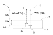
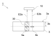
セメント水混練体3の強度発現量の高低によって、反射電波信号W2の強度が変化する点につき、図3A及び図3Bを参照して説明する。図3Aは、セメント水混練体3の強度発現量q3が比較的高い場合に対応し、図3Bは、図3Aの状況と比べてセメント水混練体3の強度発現量q3が比較的低い場合に対応している。図3A及び図3Bでは、セメント水混練体3の強度発現量q3の高低の相違が、セメント水混練体3に付されたハッチングの密度によって模式的に表現されている。
The change in the intensity of the reflected radio wave signal W2 depending on the intensity of the cement-
上述したように、リーダライタ10からRFタグ5に向かって電波信号W1が送信されると、セメント水混練体3の表面3a(以下、適宜「セメント水混練体表面3a」と称する。)とリーダライタ10との間の離間距離h10が離れ過ぎていない限り、RFタグ5側で電波信号W1が受信され、反射電波信号W2がリーダライタ10に向かって送信される。
As described above, when a radio signal W1 is transmitted from the reader/
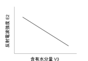
ところで、打設後のフレッシュコンクリート又は打設後のフレッシュモルタルであるセメント水混練体3は、時間の経過と共に水和反応が進行して自由水が減少する。このような現象は、セメント水混練体3の内部の特定の箇所で生じるものではなく、セメント水混練体3の全体にわたって生じる。つまり、セメント水混練体3の含有水分量V3が少なくなるほど、セメント水混練体3の強度発現量q3は上昇することが分かる。言い換えれば、セメント水混練体3の含有水分量V3と、セメント水混練体3の貫入抵抗値Qとは、図4Aに示すように負の相関を示す。この貫入抵抗値Qは、セメント水混練体3の強度発現量q3に置き換えることができる。
Now, in the
ここで、セメント水混練体3の含有水分量V3の多寡は、RFタグ5とセメント水混練体表面3aとの間の領域3b内における水分量の多寡に影響を及ぼす。水は導電性を示すことから、反射電波信号W2の伝播経路内に存在する水の量に応じて、この反射電波信号W2の強度が低下する。
Here, the amount of moisture V3 contained in the cement-
上述したように、図3Bは、図3Aよりもセメント水混練体3の強度発現量q3が低い状況が模擬されている。このことは、図3Bの状態では、RFタグ5とセメント水混練体表面3aとの間の領域3b内に含まれる水分量、言い換えれば反射電波信号W2の伝播経路内に存在する水分量が、図3Aの状態よりも多いことを意味する。つまり、図3Aの状態においてリーダライタ10で受信される反射電波信号W2の強度がE2xである場合、図3Aよりも含有水分量の多い図3Bの状態においては、リーダライタ10で受信される反射電波信号W2の強度はE2xよりも低いE2yとなる。
As described above, FIG. 3B simulates a situation in which the strength expression amount q3 of the cement-
以上により、セメント水混練体3内に含まれる水分量(含有水分量V3)を横軸に取り、反射電波信号W2の強度E2(以下、適宜「反射電波強度E2」と称する。)を縦軸に取ってグラフ化すると、図4Bに示すように両者は負の相関を示す。より詳細には、反射電波強度E2は、含有水分量V3に対して実質的に反比例の関係を示す。なお、図4Bは、あくまで模式的に示したグラフであり、反射電波強度E2がセメント水混練体3内の含有水分量V3に対して、厳密な意味で反比例の関係であることに限定する意図はない。図4Aも同様である。
When the amount of water contained in the cement-water mixture 3 (water content V3) is plotted on the horizontal axis and the intensity E2 of the reflected radio wave signal W2 (hereinafter referred to as "reflected radio wave intensity E2") is plotted on the vertical axis, the two show a negative correlation, as shown in FIG. 4B. More specifically, the reflected radio wave intensity E2 is substantially inversely proportional to the water content V3. Note that FIG. 4B is merely a schematic graph, and is not intended to limit the relationship between the reflected radio wave intensity E2 and the water content V3 in the cement-
図4A及び図4Bの結果から、反射電波強度E2(E2x,E2y)は、セメント水混練体3全体にわたる含有水分量V3に依存し、この含有水分量V3はセメント水混練体3の強度発現量q3を示す指標となることが分かる。従って、反射電波強度E2(E2x,E2y)の値によって、セメント水混練体3の強度発現量q3の推定が可能である。
From the results of Figures 4A and 4B, it can be seen that the reflected radio wave intensity E2 (E2x, E2y) depends on the moisture content V3 throughout the cement-
図5は、打設後のフレッシュコンクリート又はフレッシュモルタルにおける含有水分量V3及び反射電波強度E2の経時的な変化を模式的に示すグラフである。図5に示すように、打設後の時間経過と共に水和反応が進展する結果、含有水分量V3が低下するため、リーダライタ10で受信される反射電波強度E2は経時的に増加傾向を示す。なお、上述したように、含有水分量V3と貫入抵抗値Qは負の相関を示すことから、貫入抵抗値Qに対応する指標である強度発現量q3は、図5において反射電波強度E2と同様に右肩上がりのカーブを描く。
Figure 5 is a graph showing the change over time in the moisture content V3 and reflected radio wave intensity E2 in fresh concrete or fresh mortar after pouring. As shown in Figure 5, as the hydration reaction progresses over time after pouring, the moisture content V3 decreases, and the reflected radio wave intensity E2 received by the reader/
以上のように、本実施形態の推定システム1によれば、セメント水混練体3を構成するコンクリートやモルタルが、打設された後まだ十分に硬化していない施工段階において、供試体を用いることなく簡易な方法で、セメント水混練体3の強度発現量q3を推定することが可能となる。
As described above, the
具体的には、図4A及び図4Bを参照して上述したように、セメント水混練体3の強度発現量q3と反射電波強度E2とは一定の相関関係を示すことから、この相関関係が規定された情報(以下、「相関情報」と称する。)を予め記憶部22に記録しておくものとして構わない。これにより、推定処理部21は、通信部11で受信された反射電波強度E2に関する情報を、記憶部22に記録された相関情報と照合することで、セメント水混練体3の強度発現量q3の推定値を算定できる。つまり、リーダライタ10によって、反射電波強度E2が測定され(工程(c)に対応)、この反射電波強度E2と前記相関情報とに基づいて強度発現量q3が推定される(工程(d)に対応)。
Specifically, as described above with reference to Figures 4A and 4B, the strength expression amount q3 of the cement-
この相関情報は、強度発現量q3と反射電波強度E2との関係が表記されていればよく、その表記方法には限定されない。すなわち、相関情報は、データテーブルの形式で記載されていても構わないし、関数の形式で記載されていても構わない。 This correlation information is not limited to a particular representation method as long as it represents the relationship between the intensity expression amount q3 and the reflected radio wave intensity E2. In other words, the correlation information may be represented in the form of a data table or a function.
また、記憶部22に記録される相関情報としては、事前にセメント水混練体3と同種の材料からなる供試体を用いて測定されたデータを利用することができる。この場合、強度発現量q3の値としては、例えば貫入抵抗値Qに基づく相対値を採用することができる。なお、この供試体はあくまで記憶部22に記録するための情報を得る際に用いられるものであって、推定処理の実行時に用いられるものではないことを確認のために付言しておく。
In addition, as the correlation information recorded in the
(別態様)
ところで、上述した方法は、反射電波信号W2の強度(反射電波強度E2)の値に基づいて強度発現量q3を推定するものであり、言い換えれば、強度発現量q3を推定するための基礎となる指標値が反射電波強度E2であった。しかし、リーダライタ10によっては、反射電波信号W2を受信する機能を有していても、その強度値については計測できないものも存在する。
(Another embodiment)
Incidentally, the above-mentioned method estimates the intensity expression amount q3 based on the value of the intensity of the reflected radio wave signal W2 (reflected radio wave intensity E2), in other words, the index value serving as the basis for estimating the intensity expression amount q3 is the reflected radio wave intensity E2. However, some reader/
かかる場合には、リーダライタ10とセメント水混練体表面3aとの離間距離h10(図3A参照)を変えながら、リーダライタ10が反射電波信号W2を検知できる離間距離h10の最大値(以下、「離間距離上限閾値h10max」と称する。)を、強度発現量q3を推定するための基礎となる指標値としても構わない。
In such a case, the maximum value of the distance h10 (see FIG. 3A) at which the reader/
図6は、含有水分量V3と通信距離d2との関係を図4Bにならって模式的に示すグラフである。なお、ここでいう通信距離d2とは、リーダライタ10側で反射電波信号W2を検知できる、リーダライタ10とRFタグ5との離間距離の上限閾値を指す。
Figure 6 is a graph showing the relationship between the moisture content V3 and the communication distance d2, following the example of Figure 4B. Note that the communication distance d2 here refers to the upper threshold value of the distance between the reader/
RFタグ5から送信される反射電波信号W2がセメント水混練体3内を通過した後の、当該反射電波信号W2が示す強度E2(反射電波強度E2)が比較的高い場合には、リーダライタ10をRFタグ5から比較的遠ざけたとしてもリーダライタ10が反射電波信号W2を検知できる。一方、反射電波強度E2が比較的低い場合には、リーダライタ10をRFタグ5に近づけなければリーダライタ10が反射電波信号W2を検知できない。
When the reflected radio wave signal W2 transmitted from the
つまり、反射電波強度E2と通信距離d2とは正の相関にあり、より詳細には実質的に比例関係にあるといえる。図6と図4Bとを比較すると、縦軸が反射電波強度E2であるか通信距離d2であるかが相違するのみで、含有水分量V3との比較関係は近似している。 In other words, the reflected radio wave intensity E2 and the communication distance d2 are positively correlated, and more specifically, are substantially proportional to each other. Comparing FIG. 6 with FIG. 4B, the only difference is whether the vertical axis is the reflected radio wave intensity E2 or the communication distance d2, but the comparative relationship with the moisture content V3 is similar.
通信距離d2は、前述した離間距離上限閾値h10maxと、セメント水混練体3内におけるRFタグ5の埋設深さとの合計値に対応する。セメント水混練体3内におけるRFタグ5の埋設深さは、同一の現場においては変化するものではない。従って、実質的に離間距離上限閾値h10maxによって、含有水分量V3に依存するセメント水混練体3の強度発現量q3を推定することが可能である。
The communication distance d2 corresponds to the sum of the upper threshold value h10max and the buried depth of the
この方法による場合には、強度発現量q3と離間距離上限閾値h10maxとの相関関係が規定された情報(上述した「相関情報」に対応する。)が記憶部22に記録されているものとしても構わない。この場合の相関情報としては、例えば、強度発現量q3と反射電波強度E2の相関情報を得る場合と同様の手法により得られたものを利用できる。
When this method is used, information that specifies the correlation between the intensity expression amount q3 and the upper threshold value of the distance h10max (corresponding to the "correlation information" described above) may be recorded in the
また、強度発現量q3と通信距離d2との相関情報が記憶部22に記録されているものとしても構わない。この場合には、記憶部22に予めセメント水混練体3内におけるRFタグ5の埋設深さについての情報が記録されており、この埋設深さと離間距離上限閾値h10maxの情報とに基づいて、対象となるセメント水混練体3の通信距離d2を算定した上で、前記相関情報から強度発現量q3が推定できる。なお、図11を参照して後述するように、RFタグ5側に埋設深さについての情報が予め記憶されている場合には、埋設深さに関する情報を記憶部22に記録しておく必要はなく、リーダライタ10側で反射電波信号W2を受信する際に併せて埋設深さについての情報を受信すればよい。
In addition, correlation information between the intensity expression amount q3 and the communication distance d2 may be recorded in the
なお、リーダライタ10が反射電波強度E2を検知できる構成であっても、推定装置20が離間距離上限閾値h10maxに基づいて強度発現量q3を推定するものとしても構わない。
Even if the reader/
[第二実施形態]
推定システム1の第二実施形態について、図7及び図8を参照して説明する。なお、図7では、図示の都合上、電波信号(E1,E2)のうち、電波信号W1の図示が省略され、反射電波信号W2のみが図示されている。以下の図面においても、電波信号W1の図示が省略されることがある。
[Second embodiment]
A second embodiment of the
第一実施形態で上述した推定システム1において、反射電波強度E2に基づいて強度発現量q3を推定する場合には、リーダライタ10とセメント水混練体表面3aとの離間距離h10(図3A、図3B参照)を、可能な限り所定の値に保持する必要がある。なぜなら、離間距離h10が変化してしまうと、反射電波強度E2が変化し、強度発現量q3を正しく推定できなくなるおそれがあるためである。
In the
しかし、測定対象となるセメント水混練体3の周辺環境等の事情によっては、離間距離h10を所定の値に保持しながらリーダライタ10を配置することが困難な場合がある。
However, depending on circumstances such as the surrounding environment of the cement-
本実施形態の推定システム1は、リーダライタ10の位置が固定できない場合であっても、精度よくセメント水混練体3の強度発現量q3を推定できる構成であって、セメント水混練体3内において埋設深さの異なる第一RFタグ5aと第二RFタグ5bとを含む。より詳細には、図7に示すように、セメント水混練体3内には、埋設深さh5aの位置に第一RFタグ5aが埋設されており、埋設深さh5aよりも深い埋設深さh5bの位置に第二RFタグ5bが埋設されている。これらのRFタグ(5a,5b)を埋設する工程が、工程(a)に対応する。
The
リーダライタ10は、RFタグ(5a,5b)からそれぞれ反射電波信号(W2a,W2b)を受信する(工程(c)に対応)。第一RFタグ5aは、第二RFタグ5bよりもセメント水混練体3の表面3aに近い位置に埋設されているため、第一RFタグ5aからの反射電波信号W2aの強度E2aは、第二RFタグ5bからの反射電波信号W2bの強度E2bよりも高くなる。以下では、第一RFタグ5aからの反射電波信号W2aの強度E2aを「第一反射電波強度E2a」と記載し、第二RFタグ5bからの反射電波信号W2bの強度E2bを「第二反射電波強度E2b」と記載する。
The reader/
図8は、第一反射電波強度E2a及び第二反射電波強度E2bと、セメント水混練体3内の含有水分量V3との関係を、図4Bにならって模式的に示すグラフである。
Figure 8 is a graph that shows a schematic diagram of the relationship between the first reflected radio wave intensity E2a and the second reflected radio wave intensity E2b and the water content V3 in the cement-
セメント水混練体3内の含有水分量が多くなるほど、第一反射電波強度E2aと第二反射電波強度E2bとの差分値dE2は小さくなる傾向を示す。これは、セメント水混練体3内の含有水分量が多くなるに連れて、第一RFタグ5aとセメント水混練体表面3aとの間の領域内に存在する水分量と、第二RFタグ5bとセメント水混練体表面3aとの間の領域内に存在する水分量との差が小さくなるためである。
The difference value dE2 between the first reflected radio wave intensity E2a and the second reflected radio wave intensity E2b tends to become smaller as the amount of moisture contained in the
従って、第一反射電波強度E2aと第二反射電波強度E2bとの差分値dE2は、含有水分量V3の値に対して負の相関を示す。このことは、第一反射電波強度E2aと第二反射電波強度E2bとの差分値dE2が、強度発現量q3に対して正の相関を示すことを意味する。差分値dE2は、リーダライタ10とセメント水混練体表面3aとの離間距離h10が変化しても、殆ど又は全く変化しない。よって、予め推定装置20の記憶部22に差分値dE2と強度発現量q3との相関関係を記録しておき、推定処理部21が、通信部11で受信した各反射電波強度(E2a,E2b)の差を算出すると共に記憶部22から読み出した前記相関関係と照合することで、セメント水混練体3の強度発現量q3を推定できる(工程(d)に対応)。
Therefore, the difference value dE2 between the first reflected radio wave intensity E2a and the second reflected radio wave intensity E2b shows a negative correlation with the value of the water content V3. This means that the difference value dE2 between the first reflected radio wave intensity E2a and the second reflected radio wave intensity E2b shows a positive correlation with the intensity expression amount q3. The difference value dE2 changes little or not at all even if the separation distance h10 between the reader/
(別態様)
本実施形態の推定システムの別態様について説明する。
(Another embodiment)
Another aspect of the estimation system of the present embodiment will be described.
〈1〉 本実施形態では、第一反射電波強度E2aと第二反射電波強度E2bとの差分値dE2に基づいてセメント水混練体3の強度発現量q3を推定するものとしたが、前記差分値dE2の値に対して所定の演算を行って得られる参照値に基づいて、セメント水混練体3の強度発現量q3を推定するものとしても構わない。つまり、本実施形態では、第一RFタグ5aからの第一反射電波強度E2aを「第一指標値」とし、第二RFタグ5bからの第二反射電波強度E2bを「第二指標値」として、これらの指標値の差分値若しくは当該差分値に基づいて一意に決定される値、又は第一反射電波強度E2aと第二反射電波強度E2bとの比によって、強度発現量q3が推定される。
<1> In this embodiment, the strength expression amount q3 of the
〈2〉 本実施形態の推定システム1において、セメント水混練体3内の3種類以上の埋設深さの箇所にそれぞれRFタグ5が埋設されていても構わない。
<2> In the
〈3〉 セメント水混練体3内に埋設されていない状態において、リーダライタ10側で受信される第一反射電波強度E2aと第二反射電波強度E2bとが相違するように、第一RFタグ5aと第二RFタグ5bとが選択されるものとしても構わない。かかる構成によれば、図8に模式的に示したように、含有水分量V3に対する第一反射電波強度E2aの変位傾向と、含有水分量V3に対する第二反射電波強度E2bの変位傾向とに差をつけやすくなるため、差分値dE2に基づく強度発現量q3の推定精度が高められる。
〈3〉 The
[第三実施形態]
推定システム1の第三実施形態について、図9を参照して説明する。本実施形態の推定システム1も、第二実施形態と同様に、リーダライタ10の位置が固定できない場合であっても精度よくセメント水混練体3の強度発現量q3を推定できる構成である。本実施形態の推定システム1は、第二実施形態と同様に、セメント水混練体3内に埋設された複数のRFタグ(5a,5b)を含む。ただし、第一RFタグ5aと第二RFタグ5bとは、設置されている領域の吸水率が異なっている。
[Third embodiment]
A third embodiment of the
図9に示す例では、複数のRFタグ(5a,5b)は、一体のスペーサ30内に設置されている。このスペーサ30は、セメント水混練体3よりも吸水率の低い材料からなる第一領域31と、セメント水混練体3と同等の吸水率を示す材料からなる第二領域32とを有して構成されている。一例として、第一領域31は、超高強度コンクリート、セラミックス、ABS、ポリエチレンやポリプロピレン等の樹脂で構成される。また、第二領域32は、セメント水混練体3と同様に、モルタルやコンクリートで構成される。図9に示す例では、スペーサ30の第一領域31が「タグ保護体」に対応する。セメント水混練体3に、第一RFタグ5aと第二RFタグ5bとが設置されたスペーサ30を埋設する工程が、工程(a)に対応する。
In the example shown in FIG. 9, multiple RF tags (5a, 5b) are installed in an
第一RFタグ5aと第二RFタグ5bとは、ほぼ同じ埋設深さになるように設置される。なお、「ほぼ同じ」とは、第一RFタグ5aからの反射電波信号W2aの強度E2a(第一反射電波強度E2a)と、第二RFタグ5bからの反射電波信号W2bの強度E2b(第二反射電波強度E2b)との相違が、実質的に吸水率の相違にのみ依存すると近似可能な範囲で相違する場合を含む。具体的には、第一RFタグ5aと第二RFタグ5bの埋設深さの差が、埋設深さの10%以内の範囲内である場合を許容する。
The
リーダライタ10は、RFタグ(5a,5b)からそれぞれ反射電波信号(W2a,W2b)を受信する(工程(c)に対応)。セメント水混練体3に水分が含まれている場合であっても、第一RFタグ5aはセメント水混練体3の材料よりも吸水率の低い第一領域31内に設置されているため、第一RFタグ5aとセメント水混練体表面3aとの間の水分量は比較的少ない。これに対し、第二RFタグ5bは、セメント水混練体3と同等の吸水率を示す材料からなる第二領域32内に設置されているため、第二RFタグ5bとセメント水混練体表面3aとの間の水分量は、第一RFタグ5aとセメント水混練体表面3aとの間の水分量と比べて多くなる。
The reader/
この結果、第一RFタグ5aからの反射電波信号W2aの強度E2a(第一反射電波強度E2a)は、第二RFタグ5bからの反射電波信号W2bの強度E2b(第二反射電波強度E2b)よりも高くなる。そして、第一反射電波強度E2aと第二反射電波強度E2bの相違は、第一領域31の吸水率ε1と第二領域32の吸水率ε2との相違に由来する。つまり、第一反射電波強度E2aと第二反射電波強度E2bの相違は、第一領域31の吸水率ε1と第二領域32の吸水率ε2との比率と、セメント水混練体3内に含まれる含有水分量V3とで決定される。言い換えれば、第一反射電波強度E2aと第二反射電波強度E2bの相違は、第一領域31の吸水率ε1と第二領域32の吸水率ε2との比率と、セメント水混練体3の強度発現量q3とで決定される。
As a result, the intensity E2a (first reflected radio wave intensity E2a) of the reflected radio wave signal W2a from the
例えば、第一領域31の吸水率ε1をほぼ0とみなすことができる場合には、第一反射電波強度E2aと第二反射電波強度E2bの比率jE2によって、セメント水混練体3の強度発現量q3の推定を行うことができる。この場合には、推定装置20の記憶部22に、比率jE2と強度発現量q3との相関関係を記録しておき、推定処理部21が、通信部11で受信した各反射電波強度(E2a,E2b)の比率を算出すると共に記憶部22から読み出した前記相関関係と照合することで、セメント水混練体3の強度発現量q3を推定できる(工程(d)に対応)。
For example, when the water absorption rate ε1 of the
また、第一領域31の吸水率ε1が0と近似できない場合であっても、各吸水率(ε1、ε2)は既知であるため、第一領域31と第二領域32の吸水率の相違に伴って、強度発現量q3を、第一反射電波強度E2aと第二反射電波強度E2bとの関数で規定することが可能である。この場合には、当該関数を推定装置20の記憶部22に記録しておき、推定処理部21が、通信部11で受信した各反射電波強度(E2a,E2b)の値を記憶部22から読み出した前記関数に当てはめて演算することで、セメント水混練体3の強度発現量q3を推定できる(工程(d)に対応)。
Even if the water absorption rate ε1 of the
第二RFタグ5bは、必ずしもスペーサ30に設置される必要はない。すなわち、図10に示すように、第一RFタグ5aのみを、上述したセメント水混練体3よりも吸水率の低い材料からなるスペーサ30内に設置した上で、このスペーサ30をセメント水混練体3内に埋設するものとしても構わない。この場合、第二RFタグ5bは、スペーサ30の外側であって、第一RFタグ5aとほぼ同じ埋設深さの位置において、セメント水混練体3内に埋設される。図10に示す構成の場合には、スペーサ30自体が「タグ保護体」に対応する。
The
なお、図9に示す第一RFタグ5a及び第二RFタグ5bを備えたスペーサ30、又は、図10に示す第一RFタグ5aを備えたスペーサ30が、本発明に係る「セメント水混練体の強度発現量の推定用センサ」の一例に対応する。
The
[第四実施形態]
推定システム1の第四実施形態について、図11~図12を参照して説明する。本実施形態の推定システム1も、第二実施形態と同様に、リーダライタ10の位置が固定できない場合であっても、精度よくセメント水混練体3の強度発現量q3を推定できる構成である。
[Fourth embodiment]
A fourth embodiment of the
本実施形態の推定システム1は、第三実施形態と同様に、セメント水混練体3内に埋設されたスペーサ30を含む。ただし、スペーサ30の吸水率は限定されない。また、本実施形態の推定システム1では、スペーサ30内に設置されるRFタグ5は単独であっても構わない。
The
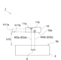
スペーサ30は、コンクリートやモルタルのかぶり厚を調整するために設けられる。よって、スペーサ30内の所定の位置にRFタグ5を設置しておけば、セメント水混練体表面3aとRFタグ5との離間距離、すなわちRFタグ5の埋設深さh5を施工前の段階から認識できる。すなわち、RFタグ5に対して、埋設深さh5の情報(深さ情報)を書き込むことが可能である。埋設深さh5の情報が書き込まれたRFタグ5が設置されてなるスペーサ30を、セメント水混練体3内に埋設する工程が、工程(a)に対応する。
The
リーダライタ10は、RFタグ5から反射電波信号W2を受信する(工程(c)に対応)。この際、リーダライタ10は、RFタグ5に記録された埋設深さh5の情報についても併せて読み出す。
The reader/
本実施形態のリーダライタ10は、図12に示すように測距センサ23を備えており、セメント水混練体表面3aで反射したセンシング信号i23によって、リーダライタ10とセメント水混練体表面3aとの離間距離h10を測定することができる。
The reader/
ここで、反射電波信号W2の空気中の通信距離(離間距離h10)によって変動する係数をα、反射電波信号W2の乾燥状態のセメント水混練体3中の通信距離(埋設深さh5)によって変動する係数をβ、反射電波信号W2のセメント水混練体3中の水分量V3によって変動する係数をγとすると、反射電波強度E2は以下の(1)式で評価できる。
E2 = α・h10+(β・h5)・γ …(1)
Here, if the coefficient that varies with the communication distance in the air (separation distance h10) of the reflected radio wave signal W2 is α, the coefficient that varies with the communication distance in the dry cement-water mixture 3 (burial depth h5) of the reflected radio wave signal W2 is β, and the coefficient that varies with the moisture content V3 in the cement-
E2 = α・h10+(β・h5)・γ…(1)
つまり、以下の(2)式によって、セメント水混練体3中の含有水分量V3の関数で規定されるγの値が算定される。
γ = (E2 - α・h10)/(β・h5) …(2)
That is, the value of γ defined as a function of the water content V3 in the cement-
γ = (E2 - α・h10)/(β・h5) …(2)
そして、上述したように、セメント水混練体3の強度発現量q3は、セメント水混練体3の含有水分量V3によって決定されるため、前記係数γの値によって決定されるともいえる。
As described above, the strength development amount q3 of the cement-
記憶部22には、予め、離間距離h10と係数αの関係、埋設深さh5と係数βの関係、セメント水混練体3の強度発現量q3と係数γの関係、及び上記(2)式に対応する評価式に関する情報がそれぞれ記録されている。上述したように、推定装置20側では、離間距離h10及び埋設深さh5についての情報を検知できる。よって、推定処理部21は、離間距離h10及び埋設深さh5に関する情報から、係数α及び係数βの値を演算で導出できる。そして、推定処理部21は、反射電波強度E2、係数α、及び係数βの値を(2)式に代入して係数γを算定した上で、記憶部22に記録された強度発現量q3と係数γとの関係から、算定されたγの値に対応する強度発現量q3を導出できる。
The
上記(2)式はあくまで説明のために一例として記載したものであり、演算に際しては、必ずしもこの式に基づかなくてはならないものではない。本実施形態の推定システム1は、RFタグ5から読み出された埋設深さh5に関する情報と、反射電波強度E2と、リーダライタ10とセメント水混練体表面3aとの離間距離h10に関する情報とを用いて、セメント水混練体3の強度発現量q3の推定値を算定する方法を包含する。
The above formula (2) is described as an example for the purpose of explanation only, and calculations do not necessarily have to be based on this formula. The
また、リーダライタ10とセメント水混練体表面3aとの離間距離h10を測定する方法は任意である。つまり、リーダライタ10側に、前記離間距離h10を測定する機能が搭載されていなくても構わない。
The method for measuring the distance h10 between the reader/
なお、図11に示す第一RFタグを備えたスペーサ30が、本発明に係る「セメント水混練体の強度発現量の推定用センサ」の一例に対応する。
The
[別実施形態]
以下、別実施形態について説明する。
[Another embodiment]
Another embodiment will now be described.
〈1〉 図13に示すように、推定装置20は、リーダライタ10とは別体の装置で構成されていても構わない。この場合、リーダライタ10で受信した反射電波信号W2の強度に関する情報は、推定装置20に対して有線又は無線を介して送信され、推定装置20側において、受信した情報に基づいて演算処理が行われて強度発現量q3が推定される。
<1> As shown in FIG. 13, the
〈2〉 上記実施形態では、RFタグ5(5a,5b)が金属非対応のRFタグであるものとしたが、例えばスペーサ30を鉄筋に固定する場合など、裏面側の近傍に金属材料が存在する場合には、RFタグ5(5a,5b)を金属対応のRFタグ(メタルタグ)としても構わない。
<2> In the above embodiment, the RF tag 5 (5a, 5b) is an RF tag that is not compatible with metals. However, if a metal material is present near the back side, for example when the
〈3〉 上述した第二実施形態では、埋設深さの異なる2種類のRFタグ(5a,5b)を用いると共に、これらのRFタグ(5a,5b)のそれぞれから送信された反射電波信号(W2a,W2b)の差分値や比率に基づく値に基づいて、強度発現量q3を推定する構成であった。これに対し、リーダライタ10側において、異なる位置に複数の通信部11を設けることで、それぞれの通信部11とRFタグ5との離間距離の複数種類にするものとしても構わない(例えば図14参照)。
〈3〉 In the second embodiment described above, two types of RF tags (5a, 5b) with different buried depths are used, and the intensity expression amount q3 is estimated based on a value based on the difference or ratio of the reflected radio wave signals (W2a, W2b) transmitted from each of these RF tags (5a, 5b). In contrast, by providing
図14は、この別実施形態の推定システム1の構成を模式的に示す図面である。リーダライタ10は、複数の通信部(11a,11b)を搭載している。この通信部(11a,11b)は例えばアンテナであり、このうちの少なくとも1つのアンテナが外付けであっても構わない。これらの通信部(11a,11b)は、相互に、セメント水混練体表面3aとの離間距離を異ならせることができるような位置に設置されている。より詳細には、これらの通信部(11a,11b)は、リーダライタ10の面のうち、測定対象となるセメント水混練体3に対向する面10aからの距離(h11a,h11b)がそれぞれ異なる位置に設置される。図14の例によれば、通信部11aとセメント水混練体表面3aとの離間距離は、h10とh11aの合計値に対応し、通信部11bとセメント水混練体表面3aとの離間距離は、h10とh11bの合計値に対応する。
Figure 14 is a diagram showing a schematic configuration of the
この構成の場合、リーダライタ10は、搭載した2つの通信部(11a,11b)において、RFタグ5からそれぞれ反射電波信号(W2a,W2b)を受信する。これらの反射電波信号の強度(E2a,E2b)の差分値又は比率は、リーダライタ10の表面とセメント水混練体表面3aとの離間距離h10が変動しても、セメント水混練体3内の含有水分量V3に依存した値となり、言い換えれば、強度発現量q3に依存した値となる。この結果、測定時に前記離間距離h10を所定の値に保持できない事情がある場合であっても、上記実施形態と同様に、セメント水混練体3内の強度発現量q3を推定できる。
In this configuration, the reader/
以下、実施例を参照して説明する。 The following is an explanation with reference to examples.
下記表1及び表2に示す材料からなる試験用モルタルを打設し、JIS A 1147に準拠する方法で、所定時間の経過と共に貫入抵抗値を測定しながら、硬化時間を計測した。この評価結果を図15に示す。なお、図15において、貫入抵抗値が3.5N/mm2に達した時点を「始発」と記載し、28.0N/mm2に達した時点を「終結」と記載している。なお、表1において、W/Cは水セメント比を指し、S/Cは砂セメント比を指す。 Test mortar made of the materials shown in Tables 1 and 2 below was poured, and the hardening time was measured while measuring the penetration resistance value over a predetermined time period in a manner conforming to JIS A 1147. The evaluation results are shown in Figure 15. In Figure 15, the point at which the penetration resistance value reached 3.5 N/ mm2 is described as "initial" and the point at which it reached 28.0 N/ mm2 is described as "final." In Table 1, W/C refers to the water-cement ratio, and S/C refers to the sand-cement ratio.


次に、埋設深さ4cmの位置に、横25mm×縦9mm×厚み3mmの寸法のRFタグ5を埋設した状態で上記表1の材料からなるモルタルを打設し、所定時間経過ごとに、リーダライタ10によって反射電波信号W2を受信して強度E2(反射電波強度E2)を計測した。リーダライタ10は、対応する信号の周波数が920MHz帯で、出力が250mWのものが用いられた。この計測結果を、図16A及び図16Bに示す。
Next, mortar made of the materials in Table 1 was poured with an
つまり、本実施例では、含有水分量の測定対象となるセメント水混練体3が、フレッシュモルタルによって模擬されている。
In other words, in this embodiment, the cement-
なお、計測に際しては、リーダライタ10を、モルタルの表面からの離間距離h10が90mm、120mm、150mmと異ならせた3種類の位置に設置した状態で、反射電波強度E2の計測が行われた。また、図16Bは、図16Aの一部時間帯を拡大した図面である。
When making the measurements, the reader/
図16Bによれば、打設してから終結するタイミングまでの間において、離間距離h10に関わらず、反射電波強度E2が徐々に上昇していることが確認される。このことは、セメントの水和反応が進行して硬化が進むに連れて、反射電波強度E2が上昇していることを示すものである。この結果より、反射電波強度E2に基づいてセメント水混練体3内の強度発現量q3を推定できることが分かる。
Figure 16B shows that the reflected radio wave intensity E2 gradually increases from the time of pouring to the time of completion, regardless of the separation distance h10. This shows that the reflected radio wave intensity E2 increases as the cement hydration reaction progresses and hardening progresses. From this result, it can be seen that the intensity expression amount q3 within the
また、図16Aによれば、終結の後、更に反射電波強度E2が更に上昇していることが確認される。このことは、水和反応が更に進行してセメント水混練体3(ここではモルタル)内の強度発現量q3が増加傾向にあることを示すものである。 In addition, Figure 16A shows that the reflected radio wave intensity E2 increases further after the termination. This indicates that the hydration reaction is progressing further and the strength development amount q3 in the cement-water mixture 3 (here, mortar) is tending to increase.
以上の結果から、反射電波強度E2に基づいてセメント水混練体3の強度発現量q3が推定できることが確認される。
The above results confirm that the intensity expression q3 of the cement-
1 :推定システム
3 :セメント水混練体
3a :セメント水混練体表面
3b :領域
5 :RFタグ
5a :第一RFタグ
5b :第二RFタグ
10 :リーダライタ
10a :リーダライタ表面
11 :通信部
12 :表示出力部
20 :推定装置
21 :推定処理部
22 :記憶部
23 :測距センサ
27 :報知部
30 :スペーサ
31 :第一領域
32 :第二領域
W1 :電波信号
W2,W2a,W2b:反射電波信号
E2,E2a,E2b:反射電波強度
1: Estimation system 3:
Claims (14)
前記セメント水混練体に埋設されたRFタグと、
前記RFタグとの間で電波信号の送受信が可能なリーダ又はリーダライタと、
前記リーダ又はリーダライタで受信した前記電波信号の強度値、若しくは前記電波信号の受信が検知できる前記リーダ又はリーダライタと前記セメント水混練体との離間距離の上限閾値の少なくとも一方の指標値に基づいて、前記セメント水混練体の強度発現量を推定する推定装置と、
前記指標値と前記セメント水混練体の強度発現量との相関関係に関する情報が記録された記憶部を備え、
前記推定装置は、前記記憶部から前記相関関係に関する情報を読み出して、測定された前記指標値に対応する前記セメント水混練体の強度発現量を推定することを特徴とする、セメント水混練体の強度発現量の推定システム。 A system for estimating the strength development of a cement-water mixture belonging to fresh concrete after casting or fresh mortar after casting,
An RF tag embedded in the cement-water mixture;
a reader or reader/writer capable of transmitting and receiving radio signals to and from the RF tag;
An estimation device that estimates a strength expression amount of the cement water mixture based on at least one index value of the strength value of the radio wave signal received by the reader or reader/writer, or the upper limit threshold value of the distance between the reader or reader/writer that can detect reception of the radio wave signal and the cement water mixture ;
A memory unit is provided in which information regarding the correlation between the index value and the strength development amount of the cement-water mixture is recorded,
The estimation device reads out information regarding the correlation from the memory unit and estimates the strength expression of the cement-water mixture corresponding to the measured index value .
前記推定装置は、前記第一RFタグからの前記電波信号の強度値に基づく前記指標値である第一指標値と、前記第二RFタグからの前記電波信号の強度値に基づく前記指標値である第二指標値との比較結果に基づいて、前記セメント水混練体の強度発現量を推定することを特徴とする、請求項1~3のいずれか1項に記載の、セメント水混練体の強度発現量の推定システム。 The RF tag includes a first RF tag and a second RF tag embedded at different depths in the cement-water mixture,
The system for estimating the strength expression amount of a cement-water mixture, as described in any one of claims 1 to 3, characterized in that the estimation device estimates the strength expression amount of the cement-water mixture based on a comparison result between a first index value, which is the index value based on the intensity value of the radio wave signal from the first RF tag, and a second index value, which is the index value based on the intensity value of the radio wave signal from the second RF tag.
前記RFタグは、前記タグ保護体内に埋設された第一RFタグと、前記タグ保護体の外側の位置において前記セメント水混練体内に埋設された第二RFタグとを含み、
前記推定装置は、前記第一RFタグからの前記電波信号の強度値に基づく前記指標値である第一指標値と、前記第二RFタグからの前記電波信号の強度値に基づく前記指標値である第二指標値との比較結果に基づいて、前記セメント水混練体の強度発現量を推定することを特徴とする、請求項1~3のいずれか1項に記載の、セメント水混練体の強度発現量の推定システム。 A tag protector is embedded in the cement water mixture and made of a material having a lower water absorption rate than the cement water mixture.
The RF tag includes a first RF tag embedded in the tag protector and a second RF tag embedded in the cement-water mixer at a position outside the tag protector,
The system for estimating the strength expression amount of a cement-water mixture, as described in any one of claims 1 to 3, characterized in that the estimation device estimates the strength expression amount of the cement-water mixture based on a comparison result between a first index value, which is the index value based on the intensity value of the radio wave signal from the first RF tag, and a second index value, which is the index value based on the intensity value of the radio wave signal from the second RF tag.
前記RFタグは、前記セメント水混練体の表面からの埋設深さに関する深さ情報が記録されており、
前記リーダ又はリーダライタは、前記RFタグからの前記電波信号の強度値と共に前記深さ情報を受信し、
前記推定装置は、前記リーダ又はリーダライタによって受信された前記電波信号の強度値と前記深さ情報、及び前記リーダ又はリーダライタと前記セメント水混練体との離間距離に基づいて、前記セメント水混練体の強度発現量を推定することを特徴とする、請求項1~3のいずれか1項に記載の、セメント水混練体の強度発現量の推定システム。 A spacer is embedded in the cement-water mixture and has the RF tag fixed thereto,
The RF tag has depth information recorded thereon regarding the buried depth from the surface of the cement-water mixture,
The reader or reader/writer receives the depth information together with the strength value of the radio wave signal from the RF tag,
The system for estimating the strength expression amount of a cement-water mixture according to any one of claims 1 to 3, characterized in that the estimation device estimates the strength expression amount of the cement-water mixture based on the intensity value and the depth information of the radio wave signal received by the reader or reader/writer, and the distance between the reader or reader/writer and the cement-water mixture.
前記セメント水混練体にRFタグを埋設する工程(a)と、
前記セメント水混練体の外側の所定の位置に、前記RFタグとの間で電波信号の送受信が可能なリーダ又はリーダライタを配置する工程(b)と、
前記リーダ又はリーダライタで受信した前記電波信号の強度値、又は前記電波信号の受信が検知できる前記リーダ又はリーダライタと前記セメント水混練体との離間距離の上限閾値の少なくとも一方の指標値を測定する工程(c)と、
前記指標値に基づいて、前記セメント水混練体の強度発現量を推定する工程(d)とを有し、
前記工程(d)は、前記指標値と前記セメント水混練体の強度発現量との相関関係に関する情報を読み出す工程を含むと共に、読み出された前記相関関係に基づいて、前記工程(c)で測定された前記指標値に対応する前記セメント水混練体の強度発現量を推定する工程であることを特徴とする、セメント水混練体の強度発現量の推定方法。 A method for estimating a strength development amount of a cement-water mixture belonging to fresh concrete after casting or fresh mortar after casting, comprising:
A step (a) of embedding an RF tag in the cement-water mixture;
(b) a step of disposing a reader or reader/writer capable of transmitting and receiving radio signals to and from the RF tag at a predetermined position outside the cement-water kneaded body;
(c) measuring at least one of the index values of the intensity value of the radio wave signal received by the reader or reader/writer, or the upper limit threshold value of the distance between the reader or reader/writer and the cement-water mixture at which reception of the radio wave signal can be detected;
and (d) estimating a strength development amount of the cement water mixture based on the index value ,
The method for estimating the strength expression of a cement-water mixture, wherein the step (d) includes a step of reading out information relating to a correlation between the index value and the strength expression of the cement-water mixture, and a step of estimating the strength expression of the cement-water mixture corresponding to the index value measured in the step (c) based on the read-out correlation .
前記工程(d)は、前記工程(c)で測定された前記指標値が経時的に増加傾向を示すことを検知すると前記セメント水混練体の強度発現量が増加したことを推定する工程であることを特徴とする、請求項8に記載の、セメント水混練体の強度発現量の推定方法。 The step (c) is a step of measuring the index value continuously or intermittently,
The method for estimating the strength development amount of a cement-water mixture according to claim 8, characterized in that the step (d) is a step of estimating that the strength development amount of the cement-water mixture has increased when it is detected that the index value measured in the step ( c) shows an increasing tendency over time.
前記工程(c)は、前記第一RFタグからの前記電波信号の強度値に基づく前記指標値である第一指標値と、前記第二RFタグからの前記電波信号の強度値に基づく前記指標値である第二指標値とを測定する工程を含み、
前記工程(d)は、前記第一指標値と前記第二指標値との比較結果に基づいて、前記セメント水混練体の強度発現量を推定する工程を含むことを特徴とする、請求項8~10のいずれか1項に記載の、セメント水混練体の強度発現量の推定方法。 The step (a) includes a step of embedding a first RF tag and a second RF tag at positions having different embedment depths in the cement-water mixer,
The step (c) includes a step of measuring a first index value, which is the index value based on the intensity value of the radio wave signal from the first RF tag, and a second index value, which is the index value based on the intensity value of the radio wave signal from the second RF tag;
The method for estimating a strength development amount of a cement-water mixture according to any one of claims 8 to 10 , characterized in that the step (d) includes a step of estimating a strength development amount of the cement-water mixture based on a comparison result between the first index value and the second index value.
前記工程(c)は、前記第一RFタグからの前記電波信号の強度値に基づく前記指標値である第一指標値と、前記第二RFタグからの前記電波信号の強度値に基づく前記指標値である第二指標値とを測定する工程を含み、
前記工程(d)は、前記第一指標値と前記第二指標値との比較結果に基づいて、前記セメント水混練体の強度発現量を推定する工程を含むことを特徴とする、請求項8~10のいずれか1項に記載の、セメント水混練体の強度発現量の推定方法。 The step (a) includes a step of embedding a first RF tag embedded in a tag protector made of a specific material having a lower water absorption rate than the cement-water mixture, and a second RF tag disposed at an outer position of the tag protector, together with the tag protector, in the cement-water mixture,
The step (c) includes a step of measuring a first index value, which is the index value based on the intensity value of the radio wave signal from the first RF tag, and a second index value, which is the index value based on the intensity value of the radio wave signal from the second RF tag;
The method for estimating a strength development amount of the cement-water mixture according to any one of claims 8 to 10 , characterized in that the step (d) includes a step of estimating a strength development amount of the cement-water mixture based on a comparison result between the first index value and the second index value.
前記工程(a)は、前記深さ情報が記憶された前記RFタグが固定されたスペーサごと前記セメント水混練体内に埋設する工程を含み、
前記工程(c)は、前記リーダ又はリーダライタによって受信された前記電波信号の強度値と前記深さ情報を読み出す工程を含み、
前記工程(d)は、前記リーダ又はリーダライタと前記セメント水混練体との離間距離を検知する工程を含むと共に、当該離間距離に関する情報と、前記工程(c)で読み出された前記電波信号の強度値及び前記深さ情報とに基づいて、前記セメント水混練体の強度発現量を推定することを特徴とする、請求項8~10のいずれか1項に記載の、セメント水混練体の強度発現量の推定方法。 The RF tag has depth information recorded thereon regarding the buried depth from the surface of the cement-water mixture,
The step (a) includes a step of embedding the spacer, to which the RF tag having the depth information stored therein is fixed, in the cement-water mixer,
The step (c) includes a step of reading out the intensity value and the depth information of the radio wave signal received by the reader or reader/writer,
The method for estimating the strength expression amount of a cement-water mixture according to any one of claims 8 to 10, characterized in that the step (d) includes a step of detecting a distance between the reader or reader/writer and the cement-water mixture, and estimating a strength expression amount of the cement-water mixture based on information on the distance, and the intensity value of the radio wave signal read out in the step (c) and the depth information.
前記RFタグと、前記スペーサとを備え、
前記スペーサは、前記RFタグが内側に固定され、前記セメント水混練体内における前記RFタグの埋設深さを調整することを特徴とする、セメント水混練体の強度発現量の推定用センサ。
A sensor for estimating the strength development amount of a cement-water mixture, which is included in the system for estimating the strength development amount of a cement-water mixture according to claim 6 ,
The RF tag and the spacer are provided,
The sensor for estimating the strength development amount of a cement-water mixture is characterized in that the spacer has the RF tag fixed inside and adjusts the embedding depth of the RF tag within the cement-water mixture.
Priority Applications (1)
| Application Number | Priority Date | Filing Date | Title |
|---|---|---|---|
| JP2020162941A JP7561558B2 (en) | 2020-09-29 | 2020-09-29 | System for estimating strength development amount of cement-water mixture, method for estimating strength development amount of cement-water mixture, and sensor for estimating strength development amount of cement-water mixture |
Applications Claiming Priority (1)
| Application Number | Priority Date | Filing Date | Title |
|---|---|---|---|
| JP2020162941A JP7561558B2 (en) | 2020-09-29 | 2020-09-29 | System for estimating strength development amount of cement-water mixture, method for estimating strength development amount of cement-water mixture, and sensor for estimating strength development amount of cement-water mixture |
Publications (2)
| Publication Number | Publication Date |
|---|---|
| JP2022055488A JP2022055488A (en) | 2022-04-08 |
| JP7561558B2 true JP7561558B2 (en) | 2024-10-04 |
Family
ID=80998910
Family Applications (1)
| Application Number | Title | Priority Date | Filing Date |
|---|---|---|---|
| JP2020162941A Active JP7561558B2 (en) | 2020-09-29 | 2020-09-29 | System for estimating strength development amount of cement-water mixture, method for estimating strength development amount of cement-water mixture, and sensor for estimating strength development amount of cement-water mixture |
Country Status (1)
| Country | Link |
|---|---|
| JP (1) | JP7561558B2 (en) |
Citations (6)
| Publication number | Priority date | Publication date | Assignee | Title |
|---|---|---|---|---|
| JP2006071575A (en) | 2004-09-06 | 2006-03-16 | Taiheiyo Cement Corp | Concrete management method and embedded RFID module |
| JP2006309410A (en) | 2005-04-27 | 2006-11-09 | Ohbayashi Corp | Casting status monitoring method, casting status monitoring device, casting status monitoring program, and mold form |
| JP2008093991A (en) | 2006-10-12 | 2008-04-24 | Taiheiyo Cement Corp | RFID tag mounting jig and RFID tag mounting method |
| JP2011063955A (en) | 2009-09-15 | 2011-03-31 | Seiko Epson Corp | Management method, communication device, and transport equipment |
| JP2018009821A (en) | 2016-07-12 | 2018-01-18 | 飛島建設株式会社 | Concrete demold time strength estimation system |
| JP2020008328A (en) | 2018-07-03 | 2020-01-16 | 太平洋セメント株式会社 | Corrosion detection sensor, corrosive environment detection method |
-
2020
- 2020-09-29 JP JP2020162941A patent/JP7561558B2/en active Active
Patent Citations (6)
| Publication number | Priority date | Publication date | Assignee | Title |
|---|---|---|---|---|
| JP2006071575A (en) | 2004-09-06 | 2006-03-16 | Taiheiyo Cement Corp | Concrete management method and embedded RFID module |
| JP2006309410A (en) | 2005-04-27 | 2006-11-09 | Ohbayashi Corp | Casting status monitoring method, casting status monitoring device, casting status monitoring program, and mold form |
| JP2008093991A (en) | 2006-10-12 | 2008-04-24 | Taiheiyo Cement Corp | RFID tag mounting jig and RFID tag mounting method |
| JP2011063955A (en) | 2009-09-15 | 2011-03-31 | Seiko Epson Corp | Management method, communication device, and transport equipment |
| JP2018009821A (en) | 2016-07-12 | 2018-01-18 | 飛島建設株式会社 | Concrete demold time strength estimation system |
| JP2020008328A (en) | 2018-07-03 | 2020-01-16 | 太平洋セメント株式会社 | Corrosion detection sensor, corrosive environment detection method |
Also Published As
| Publication number | Publication date |
|---|---|
| JP2022055488A (en) | 2022-04-08 |
Similar Documents
| Publication | Publication Date | Title |
|---|---|---|
| US12379366B2 (en) | Embedded wireless monitoring sensors | |
| US20220146488A1 (en) | Sensing device, sensing device system, and methods for measuring a characteristic of a concrete mixture and for predicting a performance characteristic of a concrete mixture | |
| US6429802B1 (en) | Determining the condition of a concrete structure using electromagnetic signals | |
| US6772091B1 (en) | Determining the depth of reinforcing bars in a concrete structure using electromagnetic signals | |
| CN112819781B (en) | Concrete roughening quality assessment method, device and system | |
| EP3408670A1 (en) | Systems, apparatus and methods for obtaining measurements concerning the strength and performance of concrete mixtures | |
| Craeye et al. | On-site strength assessment of limestone based concrete slabs by combining non-destructive techniques | |
| Chrisp et al. | Depth-related variation in conductivity to study cover-zone concrete during wetting and drying | |
| WO2015150463A1 (en) | Corrosion detection system and method in concrete structures | |
| JP7561558B2 (en) | System for estimating strength development amount of cement-water mixture, method for estimating strength development amount of cement-water mixture, and sensor for estimating strength development amount of cement-water mixture | |
| Ranz et al. | Monitoring of the curing process in precast concrete slabs: An experimental study | |
| US20070095139A1 (en) | Method and apparatus for non-destructive testing of concrete structures | |
| JP7441152B2 (en) | System for estimating the amount of water contained in a cement water kneaded product, method for estimating the amount of water contained in a cement water kneaded product, and sensor for estimating the amount of water contained in a cement water kneaded product | |
| JP6497707B2 (en) | Strength estimation system for concrete demolding | |
| EP1780539A1 (en) | Method and apparatus for non-destructive ultrasonic testing of concrete structures | |
| KR100805184B1 (en) | Quality Evaluation Method of Concrete Lining According to Blasting Vibration in Tunnel Excavation | |
| JP2022080719A (en) | Prediction method of construction timing, prediction device and concrete construction method | |
| KR20040001712A (en) | Apparatus and Method For Detecting Steel Reinforcing In Reinforced Concrete Structure Using Radar System | |
| KR20230155137A (en) | Method for monitoring initial strength of concrete using internal relative humidity hysteresis and diagnosis system | |
| JP2022079221A (en) | Prediction method, prediction device of construction timing of concrete, and construction method of concrete | |
| JP7145001B2 (en) | Ground strength estimation method | |
| Moldenhauer et al. | Experimental modeling approach for determining the moisture damping exponent of a bluetooth low energy signal in moist building material | |
| JP7160848B2 (en) | pavement recovery | |
| Hird et al. | One-dimensional compression tests on stabilized clays incorporating shear wave velocity measurements | |
| Razak et al. | Detection of sizes and locations air voids in reinforced concrete slab using ground penetrating radar and Impact-Echo methods |
Legal Events
| Date | Code | Title | Description |
|---|---|---|---|
| A621 | Written request for application examination |
Free format text: JAPANESE INTERMEDIATE CODE: A621 Effective date: 20230203 |
|
| A977 | Report on retrieval |
Free format text: JAPANESE INTERMEDIATE CODE: A971007 Effective date: 20231017 |
|
| A131 | Notification of reasons for refusal |
Free format text: JAPANESE INTERMEDIATE CODE: A131 Effective date: 20231018 |
|
| A601 | Written request for extension of time |
Free format text: JAPANESE INTERMEDIATE CODE: A601 Effective date: 20231127 |
|
| A521 | Request for written amendment filed |
Free format text: JAPANESE INTERMEDIATE CODE: A523 Effective date: 20240119 |
|
| A131 | Notification of reasons for refusal |
Free format text: JAPANESE INTERMEDIATE CODE: A131 Effective date: 20240416 |
|
| A521 | Request for written amendment filed |
Free format text: JAPANESE INTERMEDIATE CODE: A523 Effective date: 20240603 |
|
| TRDD | Decision of grant or rejection written | ||
| A01 | Written decision to grant a patent or to grant a registration (utility model) |
Free format text: JAPANESE INTERMEDIATE CODE: A01 Effective date: 20240910 |
|
| A61 | First payment of annual fees (during grant procedure) |
Free format text: JAPANESE INTERMEDIATE CODE: A61 Effective date: 20240924 |
|
| R150 | Certificate of patent or registration of utility model |
Ref document number: 7561558 Country of ref document: JP Free format text: JAPANESE INTERMEDIATE CODE: R150 |