JP7561539B2 - SUBSTRATE PROCESSING APPARATUS AND SUBSTRATE PROCESSING METHOD - Google Patents
SUBSTRATE PROCESSING APPARATUS AND SUBSTRATE PROCESSING METHOD Download PDFInfo
- Publication number
- JP7561539B2 JP7561539B2 JP2020136163A JP2020136163A JP7561539B2 JP 7561539 B2 JP7561539 B2 JP 7561539B2 JP 2020136163 A JP2020136163 A JP 2020136163A JP 2020136163 A JP2020136163 A JP 2020136163A JP 7561539 B2 JP7561539 B2 JP 7561539B2
- Authority
- JP
- Japan
- Prior art keywords
- substrate
- storage space
- processing liquid
- processing
- flow
- Prior art date
- Legal status (The legal status is an assumption and is not a legal conclusion. Google has not performed a legal analysis and makes no representation as to the accuracy of the status listed.)
- Active
Links
Images


Landscapes
- Cleaning Or Drying Semiconductors (AREA)
- Weting (AREA)
- Manufacturing Of Printed Circuit Boards (AREA)
Description
この発明は、薬液や純水などの処理液を処理槽からオーバーフローさせながら処理槽に貯留された処理液に基板を浸漬して処理する基板処理装置および基板処理方法に関するものである。 This invention relates to a substrate processing apparatus and method for processing substrates by immersing the substrate in a processing liquid, such as a chemical solution or pure water, stored in a processing tank while the processing liquid overflows from the processing tank.
半導体装置の製造分野においては、半導体装置の高密度化と大容量化に対応するために高アスペクト比の凹部を形成する技術が要望されている。例えば三次元NAND型不揮発性半導体装置(以下「3D-NANDメモリ」という)の製造過程においては、シリコン酸化膜(SiO2膜)とシリコン窒化膜(SiN膜)を多数積層した積層体に対して積層方向に凹部を形成した後、凹部を介してSiN膜をウエットエッチングにより除去する工程が含まれる。この工程を実行するために、例えば特許文献1に記載の基板処理装置を用いることが検討されている。
In the field of semiconductor device manufacturing, there is a demand for technology to form recesses with high aspect ratios to accommodate the increasing density and capacity of semiconductor devices. For example, the manufacturing process of a three-dimensional NAND nonvolatile semiconductor device (hereinafter referred to as "3D-NAND memory") includes a process of forming recesses in the stacking direction in a multi-layer structure of silicon oxide films (SiO2 films) and silicon nitride films (SiN films), and then removing the SiN films through the recesses by wet etching. To carry out this process, the use of a substrate processing apparatus, for example, as described in
基板処理装置を用いて上記ウエットエッチングを行う場合、SiN膜のエッチャントの一例であるリン酸を含む薬液が処理液として用いられる。より具体的には、基板処理装置では、処理槽の内部に形成された貯留空間の内底部に噴出管が配置され、当該噴出管から処理液が貯留空間に供給される。このため、処理槽では、処理液が処理槽からオーバーフローされながら処理槽に一定量だけ貯留される。そして、処理槽に貯留された処理液に上記凹部構造を有する基板が浸漬される。また、基板処理装置では、噴出管と同様に、気泡供給管が貯留空間の内底部に配置され、貯留空間の内底部からオーバーフロー面に向かって気泡が供給される。これらの気泡は処理液中で上昇して基板に供給される。こうした基板への気泡供給により凹部に対して新鮮な処理液を迅速かつ連続して供給することができる。 When the above wet etching is performed using a substrate processing apparatus, a chemical solution containing phosphoric acid, which is an example of an etchant for SiN films, is used as the processing liquid. More specifically, in the substrate processing apparatus, a jet pipe is disposed at the inner bottom of a storage space formed inside a processing tank, and the processing liquid is supplied from the jet pipe to the storage space. Therefore, in the processing tank, a certain amount of the processing liquid is stored in the processing tank while overflowing from the processing tank. Then, a substrate having the above recess structure is immersed in the processing liquid stored in the processing tank. In addition, in the substrate processing apparatus, a bubble supply pipe is disposed at the inner bottom of the storage space, similar to the jet pipe, and bubbles are supplied from the inner bottom of the storage space toward the overflow surface. These bubbles rise in the processing liquid and are supplied to the substrate. By supplying bubbles to the substrate in this way, fresh processing liquid can be rapidly and continuously supplied to the recess.
しかしながら、特許文献1に記載の装置では、次のような問題があった。噴出管からの処理液の噴出により貯留空間内でオーバーフロー面に向う液流、つまり処理液の上昇流が形成される。そして、貯留空間の上方開口に到達した処理液の多くはオーバーフローするが、一部はオーバーフローせずオーバーフロー面の近傍から下向きに流れる。いわゆる下降流が貯留空間内で発生する。この下降流はオーバーフロー面への気泡の上昇を阻害し、基板への気泡の均一供給を低下させる主要因のひとつとなっている。その結果、基板処理の品質低下が発生している。
However, the device described in
この発明は上記課題に鑑みなされたものであり、処理液を処理槽からオーバーフローさせながら処理槽に貯留された処理液に基板を浸漬するとともに処理液中で上記基板に気泡を供給して処理する基板処理技術において、基板に対して気泡を均一に供給して処理品質を高めることを目的とする。 This invention has been made in consideration of the above problems, and aims to improve processing quality by uniformly supplying air bubbles to a substrate in a substrate processing technique in which a substrate is immersed in a processing liquid stored in a processing tank while the processing liquid is overflowed from the processing tank and air bubbles are supplied to the substrate in the processing liquid.
この発明の第1態様は、基板処理装置であって、処理液を貯留する貯留空間を有し、貯留空間の上方開口から処理液をオーバーフローさせながら貯留空間に貯留された処理液に基板を浸漬することで基板を処理する処理槽と、貯留空間内で基板を起立姿勢で保持する基板保持部と、基板保持部に保持された基板の下方側で処理液を吐出する処理液吐出口を有し、処理液吐出口から吐出された処理液を貯留空間の内底面に向かって流す処理液吐出部と、基板保持部に保持された基板の下方側かつ処理液吐出口の上方側に設けられ、貯留空間に貯留された処理液に気泡を供給する気泡供給部と、鉛直方向における気泡供給部と貯留空間の内底面との間で、貯留空間の内底面を経由して上方に流れる処理液の少なくとも一部を分流対象液とし、分流対象液の流れを複数の上昇流に分流する分流部と、を備え、分流部は、分流対象液の上方への流れを規制して分流対象液を水平面内で振り分ける規制部位と、水平面内で規制部位に隣接しながら鉛直方向に貫通して設けられ、規制部位を経由して流れ込んで来る処理液を基板保持部に保持された基板に向けて案内する複数の貫通部位とを有し、分流対象液の流れを規制部位により複数の上昇流に分流し、貫通部位を介して基板保持部に保持された基板に案内することを特徴としている。
この発明の第2態様は、基板処理装置であって、処理液を貯留する貯留空間を有し、貯留空間の上方開口から処理液をオーバーフローさせながら貯留空間に貯留された処理液に基板を浸漬することで基板を処理する処理槽と、貯留空間内で基板を起立姿勢で保持する基板保持部と、基板保持部に保持された基板の下方側で処理液を吐出する処理液吐出口を有し、処理液吐出口から吐出された処理液を貯留空間の内底面に向かって流す処理液吐出部と、基板保持部に保持された基板の下方側かつ処理液吐出口の上方側に設けられ、貯留空間に貯留された処理液に気泡を供給する気泡供給部と、を備え、処理液吐出部は、第1水平方向に延設されるとともに側壁に処理液吐出口が複数個第1水平方向に配列して設けられる、複数のフロー管を有し、気泡供給部は、第1水平方向に延設されるとともに側壁に気泡を吐出する気泡吐出口が複数個第1水平方向に配列して設けられるバブラーを有し、バブラーは、第1水平方向と直交する第2水平方向において互いに隣接するフロー管の間に配置され、隣接するフロー管の間を流れる処理液の少なくとも一部を分流対象液とし、分流対象液の流れを複数の上昇流に分流して基板保持部に保持された基板に案内することを特徴としている。
この発明の第3態様は、基板処理装置であって、処理液を貯留する貯留空間を有し、貯留空間の上方開口から処理液をオーバーフローさせながら貯留空間に貯留された処理液に基板を浸漬することで基板を処理する処理槽と、貯留空間内で基板を起立姿勢で保持する基板保持部と、基板保持部に保持された基板の下方側で処理液を吐出する処理液吐出口を有し、処理液吐出口から吐出された処理液を貯留空間の内底面に向かって流す処理液吐出部と、基板保持部に保持された基板の下方側かつ処理液吐出口の上方側に設けられ、貯留空間に貯留された処理液に気泡を供給する気泡供給部と、を備え、処理液吐出口は基板保持部に保持された基板に向けて開口され、処理液吐出部は、処理液吐出口から吐出された処理液を貯留空間の内底面に向けて案内するカバー部材を有し、 鉛直方向における気泡供給部と貯留空間の内底面との間で、貯留空間の内底面を経由して上方に流れる処理液の少なくとも一部を分流対象液とし、分流対象液の流れを複数の上昇流に分流して基板保持部に保持された基板に案内することを特徴としている。
A first aspect of the present invention is a substrate processing apparatus comprising: a processing tank having a storage space for storing a processing liquid, and for processing a substrate by immersing the substrate in the processing liquid stored in the storage space while the processing liquid overflows from an upper opening of the storage space; a substrate holding section for holding the substrate in an upright position within the storage space; a processing liquid discharge section having a processing liquid discharge port for discharging the processing liquid below the substrate held in the substrate holding section, and for causing the processing liquid discharged from the processing liquid discharge port to flow toward an inner bottom surface of the storage space; an air bubble supply section provided below the substrate held in the substrate holding section and above the processing liquid discharge port for supplying air bubbles to the processing liquid stored in the storage space; and a diversion section which, between the supply section and the inner bottom surface of the storage space, treats at least a portion of the processing liquid flowing upward via the inner bottom surface of the storage space as a processing liquid to be diverted, and diverts the flow of the processing liquid to be diverted into a plurality of ascending flows, and the diversion section has a regulating section which regulates the upward flow of the processing liquid to be diverted and distributes the processing liquid to be diverted in a horizontal plane, and a plurality of through sections which are adjacent to the regulating section in the horizontal plane and penetrate vertically, and guide the processing liquid flowing in via the regulating sections toward the substrate held in the substrate holding section, characterized in that the flow of the processing liquid to be diverted is diverted into a plurality of ascending flows by the regulating sections , and is guided to the substrate held in the substrate holding section via the through sections .
A second aspect of the present invention is a substrate processing apparatus comprising: a processing tank having a storage space for storing a processing liquid, and for processing a substrate by immersing the substrate in the processing liquid stored in the storage space while the processing liquid overflows from an upper opening of the storage space; a substrate holding section for holding the substrate in an upright position within the storage space; a processing liquid discharge section having a processing liquid discharge port for discharging the processing liquid below the substrate held in the substrate holding section, and causing the processing liquid discharged from the processing liquid discharge port to flow toward an inner bottom surface of the storage space; and a bubble supply section provided below the substrate held in the substrate holding section and above the processing liquid discharge port for supplying bubbles into the processing liquid stored in the storage space. the processing liquid discharge section has a plurality of flow tubes extending in a first horizontal direction and having a plurality of processing liquid discharge ports arranged in the first horizontal direction on the side wall; the bubble supply section has a bubbler extending in the first horizontal direction and having a plurality of bubble discharge ports arranged in the first horizontal direction on the side wall for discharging bubbles; the bubbler is disposed between adjacent flow tubes in a second horizontal direction perpendicular to the first horizontal direction, and at least a portion of the processing liquid flowing between the adjacent flow tubes is treated as a liquid to be diverted, and the flow of the liquid to be diverted is diverted into a plurality of ascending flows to guide them to the substrate held by the substrate holding section.
A third aspect of the present invention is a substrate processing apparatus comprising: a processing tank having a storage space for storing a processing liquid, and processing a substrate by immersing the substrate in the processing liquid stored in the storage space while the processing liquid overflows from an upper opening of the storage space; a substrate holding section for holding the substrate in an upright position within the storage space; a processing liquid discharge section having a processing liquid discharge port for discharging the processing liquid below the substrate held in the substrate holding section, and causing the processing liquid discharged from the processing liquid discharge port to flow toward an inner bottom surface of the storage space; and a bubble supply section provided below the substrate held in the substrate holding section and above the processing liquid discharge port for supplying bubbles to the processing liquid stored in the storage space, wherein the processing liquid discharge port opens toward the substrate held in the substrate holding section, and the processing liquid discharge section has a cover member for guiding the processing liquid discharged from the processing liquid discharge port toward the inner bottom surface of the storage space, The present invention is characterized in that at least a portion of the processing liquid flowing upward via the inner bottom surface of the storage space between the bubble supply section in the vertical direction and the inner bottom surface of the storage space is treated as a liquid to be diverted, and the flow of the liquid to be diverted is diverted into a plurality of ascending flows and guided to the substrate held in the substrate holding section.
また、この発明の第4態様は、基板処理方法であって、処理槽に設けられた貯留空間の内底面に向かって処理液を吐出することで貯留空間に処理液を貯留するとともに貯留空間の上方開口から処理液をオーバーフローさせるオーバーフロー工程と、貯留空間に貯留された処理液に基板を浸漬させる浸漬工程と、貯留空間内の処理液に浸漬された基板の下方側より気泡供給部から気泡を供給する気泡供給工程と、を備え、オーバーフロー工程は、浸漬工程および気泡供給工程と並行して行われ、気泡供給部と貯留空間の内底面との間で貯留空間の内底面を経由して上方に流れる処理液の流れの少なくとも一部を分流対象液とし、分流対象液の上方への流れを規制して分流対象液を水平面内で振り分ける規制部位と、水平面内で規制部位に隣接しながら鉛直方向に貫通して設けられ、規制部位を経由して流れ込んで来る処理液を基板に向けて案内する複数の貫通部位とを有する分流部により、分流対象液の流れを複数の上昇流に分流して基板に案内することを特徴している。
また、この発明の第5態様は、基板処理方法であって、処理槽に設けられた貯留空間に処理液吐出部から処理液を吐出することで貯留空間に処理液を貯留するとともに貯留空間の上方開口から処理液をオーバーフローさせるオーバーフロー工程と、
貯留空間に貯留された処理液に対し、基板保持部に保持された基板を浸漬させる浸漬工程と、貯留空間内の処理液に浸漬された基板の下方側より気泡供給部から気泡を供給する気泡供給工程と、を備え、処理液吐出部は、第1水平方向に延設されるとともに側壁に処理液吐出口が複数個第1水平方向に配列して設けられる、複数のフロー管を有し、気泡供給部は、第1水平方向に延設されるとともに側壁に気泡を吐出する気泡吐出口が複数個第1水平方向に配列して設けられるバブラーを有し、バブラーは、第1水平方向と直交する第2水平方向において互いに隣接するフロー管の間に配置され、オーバーフロー工程は、浸漬工程および気泡供給工程と並行して行われ、鉛直方向における気泡供給部と貯留空間の内底面との間で、貯留空間の内底面を経由して上方に流れる処理液の少なくとも一部を分流対象液とし、隣接するフロー管の間を流れる分流対象液の流れを複数の上昇流に分流して基板保持部に保持された基板に案内することを特徴としている。
また、この発明の第6態様は、基板処理方法であって、処理槽に設けられた貯留空間に処理液吐出部の処理液吐出口から処理液を吐出することで貯留空間に処理液を貯留するとともに貯留空間の上方開口から処理液をオーバーフローさせるオーバーフロー工程と、貯留空間に貯留された処理液に対し、基板保持部に保持された基板を浸漬させる浸漬工程と、貯留空間内の処理液に浸漬された基板の下方側より気泡供給部から気泡を供給する気泡供給工程と、を備え、処理液吐出口は基板保持部に保持された基板に向けて開口され、処理液吐出部は、処理液吐出口から吐出された処理液を貯留空間の内底面に向けて案内するカバー部材を有し、オーバーフロー工程は、浸漬工程および気泡供給工程と並行して行われ、気泡供給部と貯留空間の内底面との間で、カバー部材および貯留空間の内底面の順序で経由して上方に流れる処理液の流れの少なくとも一部を複数の上昇流に分流して基板に案内することを特徴としている。
A fourth aspect of the present invention is a substrate processing method comprising: an overflow step in which the processing liquid is discharged toward an inner bottom surface of a storage space provided in a processing tank, thereby storing the processing liquid in the storage space and causing the processing liquid to overflow from an upper opening of the storage space; an immersion step in which a substrate is immersed in the processing liquid stored in the storage space; and a bubble supply step in which bubbles are supplied from a bubble supply unit from below the substrate immersed in the processing liquid in the storage space, wherein the overflow step is performed in parallel with the immersion step and the bubble supply step, and at least a part of the flow of the processing liquid flowing upward via the inner bottom surface of the storage space between the bubble supply unit and the inner bottom surface of the storage space is treated as a diverted liquid, and the flow of the diverted liquid is diverted into a plurality of upward flows and guided to the substrate by the diverting unit having a regulating portion for regulating the upward flow of the diverted liquid and distributing the diverted liquid in a horizontal plane, and a plurality of through portions adjacent to the regulating portion in the horizontal plane and penetrating in the vertical direction, the through portions providing guidance for the processing liquid flowing in via the regulating portions toward the substrate.
A fifth aspect of the present invention is a substrate processing method, comprising: an overflow process of discharging a processing liquid from a processing liquid discharger into a storage space provided in a processing tank, thereby storing the processing liquid in the storage space, and causing the processing liquid to overflow from an upper opening of the storage space;
The method includes an immersion step of immersing a substrate held by a substrate holding unit in a processing liquid stored in a storage space, and an air bubble supply step of supplying air bubbles from an air bubble supply unit to a lower side of the substrate immersed in the processing liquid in the storage space, the processing liquid discharge unit having a plurality of flow pipes extending in a first horizontal direction and having a plurality of processing liquid discharge ports arranged in the first horizontal direction on the side wall, and the air bubble supply unit having a bubble discharge port extending in the first horizontal direction and having a plurality of air bubble discharge ports arranged in the first horizontal direction on the side wall for discharging air bubbles. The bubbler is disposed between adjacent flow tubes in a second horizontal direction perpendicular to the first horizontal direction, and the overflow process is performed in parallel with the immersion process and the bubble supply process, and at least a portion of the processing liquid flowing upward via the inner bottom surface of the storage space between the bubble supply section and the inner bottom surface of the storage space in the vertical direction is treated as a liquid to be diverted, and the flow of the liquid to be diverted flowing between adjacent flow tubes is diverted into a plurality of ascending flows and guided to the substrate held by the substrate holding section.
In a sixth aspect of the present invention, there is provided a substrate processing method, comprising: an overflow step of discharging the processing liquid from a processing liquid discharge port of a processing liquid discharge unit into a storage space provided in a processing tank, thereby storing the processing liquid in the storage space and causing the processing liquid to overflow from an upper opening of the storage space; an immersion step of immersing a substrate held by a substrate holding unit in the processing liquid stored in the storage space; and a bubble supply step of supplying bubbles from a bubble supply unit from below the substrate immersed in the processing liquid in the storage space, wherein the processing liquid discharge port opens toward the substrate held by the substrate holding unit, and the processing liquid discharge unit has a cover member that guides the processing liquid discharged from the processing liquid discharge port toward an inner bottom surface of the storage space, and the overflow step is performed in parallel with the immersion step and the bubble supply step, and at least a portion of the flow of the processing liquid flowing upward between the bubble supply unit and the inner bottom surface of the storage space, passing through the cover member and the inner bottom surface of the storage space, in that order, is divided into a plurality of ascending flows and guided to the substrate.
以上のように、本発明によれば、数多くの上昇流が貯留空間に貯留された処理液内で広く分散して形成され、貯留空間内での下降流の発生が抑制される。その結果、基板に対して気泡が均一に供給され、基板処理を高品質で行うことができる。 As described above, according to the present invention, numerous upward flows are widely dispersed within the processing liquid stored in the storage space, and the occurrence of downward flows within the storage space is suppressed. As a result, air bubbles are uniformly supplied to the substrate, and substrate processing can be performed with high quality.
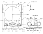
図1は本発明に係る基板処理装置の第1実施形態を装備する基板処理システムの概略構成を示す平面図である。基板処理システム1は、収納器載置部2と、シャッタ駆動機構3と、基板移載ロボット4と、姿勢変換機構5と、プッシャ6と、基板搬送機構7と、処理ユニット8と、制御部9を備えている。以下の各図における方向を統一的に示すために、図1に示すようにXYZ直交座標軸を設定する。ここでXY平面が水平面を表す。また、Z軸が鉛直軸を表し、より詳しくはZ方向が鉛直方向である。
Figure 1 is a plan view showing the schematic configuration of a substrate processing system equipped with a first embodiment of a substrate processing apparatus according to the present invention. The
収納器載置部2では、基板Wを収納した収納器が載置される。本実施形態では、収納器の一例として、水平姿勢の複数枚(たとえば25枚)の基板WをZ方向に積層した状態で収納可能に構成されたフープFが用いられている。フープFは、未処理の基板Wを収納した状態で収納器載置部2に載置されたり、処理済の基板Wを収納するために、空の状態で収納器載置部2に載置されたりする。フープFに収納される基板Wは、この実施形態では、3D-NANDメモリを形成する半導体ウエハであり、高アスペクト比の凹部を有している。
A storage container that stores substrates W is placed on the storage
収納器載置部2に対して(+Y)方向側で隣接するプロセス空間内には、シャッタ駆動機構3、基板移載ロボット4、姿勢変換機構5、プッシャ6、基板搬送機構7および処理ユニット8が配置されている。収納器載置部2とプロセス空間とは、開閉自在なシャッタ31を装備する隔壁(図示省略)により区画されている。シャッタ31はシャッタ駆動機構3に接続されている。シャッタ駆動機構3は制御部9からの閉指令に応じてシャッタ31を閉成して収納器載置部2とプロセス空間とを空間的に分離する。逆に、シャッタ駆動機構3は制御部9からの開指令に応じてシャッタ31を開放し、収納器載置部2とプロセス空間とを連通させる。これにより、フープFからプロセス空間への未処理基板Wの搬入および処理済基板WのフープFへの搬出が可能となる。
In the process space adjacent to the
上記した基板Wの搬入出処理は基板移載ロボット4によって行われる。基板移載ロボット4は水平面内で旋回自在に構成されている。基板移載ロボット4は、シャッタ31が開放された状態で、姿勢変換機構5とフープFとの間で複数枚の基板Wを受け渡しする。また、姿勢変換機構5は、基板移載ロボット4を介してフープFから基板Wを受け取った後やフープFに基板Wを受け渡す前に、複数枚の基板Wの姿勢を起立姿勢と水平姿勢との間で変換する。
The above-mentioned loading and unloading process of the substrates W is performed by the
姿勢変換機構5の基板搬送機構7側(同図中の+X方向側)にプッシャ6が配置され、姿勢変換機構5と基板搬送機構7との間で起立姿勢の複数枚の基板Wを受け渡しする。また、基板搬送機構7は、同図に示すようにプッシャ6に対向した位置(以下「待機位置」という)から処理ユニット8を構成する処理部81~85が配列された配列方向(同図中のY方向)に沿って水平方向に移動する。
The
基板搬送機構7は一対の懸垂アーム71を備えている。この一対の懸垂アーム71の揺動によって複数の基板Wを一括保持と保持解除を切替可能となっている。より具体的には、各アーム71の下縁が互いに離れる方向に水平軸周りで揺動して複数枚の基板Wを開放し、各アーム71の下縁を互いに接近させる方向に水平軸周りに揺動して複数枚の基板Wを挟持して保持する。また、図1への図示を省略しているが、基板搬送機構7はアーム移動部とアーム揺動部とを有している。これらのうちアーム移動部は、処理部81~85が配列された配列方向Yに沿って一対の懸垂アーム71を水平移動させる機能を有している。このため、この水平移動によって一対の懸垂アーム71は処理部81~85の各々に対向した位置(以下「処理位置」という)および待機位置に位置決めされる。
The
一方、アーム揺動部は上記アーム揺動動作を実行する機能を有しており、基板Wを挟持して保持する保持状態と、基板Wの挟持を解除する解除状態とを切り替える。このため、この切替動作と、処理部81、82の基板保持部として機能するリフタ810aや処理部83、84の基板保持部として機能するリフタ810bの上下動とによって、リフタ810と懸垂アーム71との間での基板Wの受け渡しを行うことが可能となっている。また、処理部85に対向する処理位置では、処理部85と懸垂アーム71との間での基板Wの受け渡しを行うことが可能となっている。さらに、待機位置では、プッシャ6を介して姿勢変換機構5と懸垂アーム71との間での基板Wの受け渡しを行うことが可能となっている。
On the other hand, the arm swinging section has a function of executing the arm swinging operation, and switches between a holding state in which the substrate W is clamped and held, and a release state in which the substrate W is released from the clamped state. Therefore, by this switching operation and the up and down movement of the
処理ユニット8には、上記したように5つの処理部81~85が設けられているが、それぞれ第1薬液処理部81、第1リンス処理部82、第2薬液処理部83、第2リンス処理部84および乾燥処理部85として機能する。これらのうち第1薬液処理部81および第2薬液処理部83は、それぞれ、同種または異種の薬液を処理槽821に貯留し、その薬液中に複数枚の基板Wを一括して浸漬させて薬液処理を施す。第1リンス処理部82および第2リンス処理部84は、それぞれ、リンス液(たとえば純水)を処理槽821に貯留し、そのリンス液中に複数枚の基板Wを一括して浸漬させて、表面にリンス処理を施すものである。これら第1薬液処理部81、第1リンス処理部82、第2薬液処理部83および第2リンス処理部84は本発明に係る基板処理装置の第1実施形態に相当しており、処理液の種類が相違するものの装置の基本構成は同一である。なお、装置構成および動作については後で図2ないし図5を参照しつつ詳述する。
As described above, the
図1に示すように、第1薬液処理部81と、これに隣接する第1リンス処理部82とが対になっており、第2薬液処理部83と、これに隣接する第2リンス処理部84とが対になっている。そして、リフタ810aは第1薬液処理部81および第1リンス処理部82において本発明の「基板保持部」として機能するのみならず、第1薬液処理部81で薬液処理された基板Wを第1リンス処理部82に移すための専用搬送機構としても機能する。また、リフタ810bは第2薬液処理部83および第2リンス処理部84において本発明の「基板保持部」として機能するのみならず、第2薬液処理部83で薬液処理された基板Wを第2リンス処理部84に移すための専用搬送機構としても機能する。
As shown in FIG. 1, the first
このように構成された処理ユニット8では、リフタ810aの3本の支持部材(図2中の符号812)が基板搬送機構7の一対の懸垂アーム71から複数枚の基板Wを一括して受け取り、後で詳述するように、処理槽から処理液をオーバーフローさせるオーバーフロー工程と処理槽に貯留された処理液内に気泡を供給する気泡供給工程とを実行しながら、第1薬液処理部81の処理槽中に下降させて薬液中に浸漬させる(浸漬工程)。さらに、所定の薬液処理時間だけ待機した後に、リフタ810aは複数枚の基板Wを保持する支持部材を薬液中から引き上げ、第1リンス処理部82へと横行させ、さらに、薬液処理済の基板Wを保持したまま支持部材を第1リンス処理部82の処理槽(図2中の符号821)内へと下降させてリンス液中に浸漬させる。所定のリンス処理時間だけ待機した後、リフタ810aは、リンス処理済の基板Wを保持したまま支持部材を上昇させてリンス液中から基板Wを引き上げる。この後、リフタ810aの支持部材から基板搬送機構7の一対の懸垂アーム71に複数枚の基板Wが一括して渡される。
In the
リフタ810bも同様に、基板搬送機構7の一対の懸垂アーム71から複数枚の基板Wを一括して受け取り、この複数枚の基板Wを第2薬液処理部83の処理槽821中に下降させて薬液中に浸漬させる。さらに、所定の薬液処理時間だけ待機した後に、リフタ810bは、支持部材を上昇させて薬液中から薬液処理済の複数枚の基板Wを引き上げ、第2リンス処理部84の処理槽へと支持部材を横行させ、さらに、この支持部材を第2リンス処理部84の処理槽821内へと下降させてリンス液中に浸漬させる。所定のリンス処理時間だけ待機した後、第2リフタ810bは、支持部材を上昇させてリンス液中から基板Wを引き上げる。この後、第2リフタ810bから基板搬送機構7に複数枚の基板Wが一括して渡される。なお、第1薬液処理部81、第1リンス処理部82、第2薬液処理部83および第2リンス処理部84の各々に本発明の「基板保持部」として機能するリフタを設ける一方、処理部81~84に対する基板Wの搬入出を基板搬送機構7や専用の搬送機構で行うように構成してもよい。
Similarly, the
乾燥処理部85は、複数枚(たとえば52枚)の基板Wを起立姿勢で配列した状態で保持することができる基板保持部材(図示省略)を有しており、減圧雰囲気中で有機溶剤(イソプロピルアルコール等)を基板Wに供給したり、遠心力によって基板W表面の液成分を振り切ったりすることにより、基板Wを乾燥させるものである。この乾燥処理部85は、基板搬送機構7の一対の懸垂アーム71との間で基板Wの受渡可能に構成されている。そして、リンス処理後の複数枚の基板Wを一括して基板搬送機構7から受け取り、この複数枚の基板Wに対して乾燥処理を施す。また、乾燥処理後においては、基板保持部材から基板搬送機構7に複数枚の基板Wが一括して渡される。
The drying
次に、本発明に係る基板処理装置について説明する。図1に示す基板処理システムに装備された第1薬液処理部81、第1リンス処理部82、第2薬液処理部83および第2リンス処理部84では、使用される処理液が一部相違しているが、装置構成および動作は基本的に同一である。そこで、以下においては、本発明に係る基板処理装置の第1実施形態に相当する第1薬液処理部81の構成および動作について説明し、第1リンス処理部82、第2薬液処理部83および第2リンス処理部84に関する説明を省略する。
Next, the substrate processing apparatus according to the present invention will be described. The first
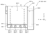
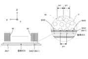
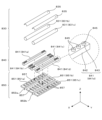
図2は本発明に係る基板処理装置の第1実施形態の概略構成を示す模式図である。図3は図2に示す基板処理装置の主要構成を模式的に示す分解組立斜視図である。図4は図2の部分断面図である。図5はリフタに保持される複数の基板と気泡吐出口との配置関係を示す模式図である。第1薬液処理部81は例えばリン酸を含む薬液を処理液として用いて基板Wの表面に形成された凹部を介してシリコン窒化膜をエッチング除去する装置である。この第1薬液処理部81は、図2および図3に示すように、基板Wに対して第1薬液処理を行うための処理槽821を備えている。この処理槽821は、平面視で長方形をなす底壁821aと、底壁821aの周囲から立ち上がる4つの側壁821b~821eとで構成された上方開口のボックス構造を有する。このため、処理槽821は底壁821aと側壁821b~821eとで囲まれた貯留空間821f内で処理液を貯留しながらリフタ810aに保持される複数の基板Wを一括して浸漬可能となっている。また、処理槽821は(+Z)方向に開口された上方開口821gを有し、当該貯留空間821fから処理液をオーバーフローさせることが可能となっている。
Figure 2 is a schematic diagram showing the outline of the first embodiment of the substrate processing apparatus according to the present invention. Figure 3 is an exploded perspective view showing the main configuration of the substrate processing apparatus shown in Figure 2. Figure 4 is a partial cross-sectional view of Figure 2. Figure 5 is a schematic diagram showing the arrangement relationship between multiple substrates held by a lifter and a bubble discharge port. The first
処理槽821の周囲にオーバーフロー槽822が設けられ、当該オーバーフロー槽822と処理槽821の側壁821b~821eとでオーバーフローした処理液を回収する回収空間822aが形成されている。また、処理槽821およびオーバーフロー槽822の下方と側方とを囲うように外容器823が設けられている。
An
オーバーフロー槽822の回収空間822aの一部、より具体的には、側壁821dの(-X)方向側の空間にフロー配管系839が配置されている。フロー配管系839のインレットは処理液供給部832に接続され、アウトレットは処理液吐出部830のフロー管831に接続されている。このため、制御部9からの処理液供給指令に応じて処理液供給部832が作動すると、処理液がフロー配管系839を介して複数のフロー管831に同時供給される。その結果、フロー管831から処理液が吐出され、貯留空間821fに貯留される。なお、フロー管831の詳しい構成などについては後で詳述する。
A
また、処理槽821からオーバーフローした処理液はオーバーフロー槽822に回収される。このオーバーフロー槽822には処理液回収部833が接続されている。制御部9からの処理液回収指令に応じて処理液回収部833が作動すると、オーバーフロー槽822に回収された処理液が処理液回収部833を経由して処理液供給部832に送液されて再利用に供せられる。このように本実施形態では、処理槽821に対して処理液を循環供給しながら処理液を貯留空間821fに貯留可能となっている。
In addition, the processing liquid that overflows from the
処理液が貯留された貯留空間821fに対して複数の基板Wを一括して保持しながら浸漬させるために、図2に示すように、リフタ810aが設けられている。このリフタ810aは、複数枚の基板Wを基板搬送機構7(図1)との間で受け渡しを行う「受渡位置」と、貯留空間821fとの間で昇降可能に構成されている。リフタ810aは、背板811と、3本の支持部材812と、延出部材813とを備えている。背板811は、処理槽821の側壁821bに沿って底壁821aに向けて延出されている。支持部材812は、背板811の下端部側面から(-X)方向に延出されている。本実施形態では、3本の支持部材812が設けられている。各支持部材812では、複数のV字状の溝812aが一定のピッチでX方向に配設されている。各溝812aは基板Wの厚さより若干幅広のV字状の溝812aが(+Z)方向に開口して形成され、基板Wを係止可能となっている。このため、3本の支持部材812によって基板搬送機構7により搬送されてくる複数の基板Wを一定の基板ピッチPT(図5)で一括して保持可能となっている。また、延出部材813は、背板811の上端部背面から(+X)方向に延出されている。リフタ810aは、図2に示すように全体としてL字状を呈している。なお、リフタ810aの最上昇位置は、基板搬送機構7が複数枚の基板Wを保持した状態であっても支持部材812の上方を通過できる高さに設定されている。
2, a
処理槽821の(+X)方向側には、リフタ駆動機構814が設けられている。リフタ駆動機構814は、昇降モータ815と、ボールネジ816と、昇降ベース817と、昇降支柱818と、モータ駆動部819とを備えている。昇降モータ815は、回転軸を縦置きにした状態で基板処理システム1のフレーム(図示省略)に取り付けられている。ボールネジ816は、昇降モータ815の回転軸に連結されている。昇降ベース817は、ボールネジ816に一方側が螺合されている。昇降支柱818は、基端部側が昇降ベース817の中央部に取り付けられ、他端部側が延出部材813の下面に取り付けられている。制御部9からの上昇指令に応じてモータ駆動部819が昇降モータ815を駆動させると、ボールネジ816が回転し、昇降ベース817とともに昇降支柱818が上昇する。これによって支持部材812が受渡位置に位置決めされる。また、制御部9からの下降指令に応じてモータ駆動部819が昇降モータ815を逆方向に駆動させると、ボールネジ816が逆回転し、昇降ベース817とともに昇降支柱818が下降する。これによって、支持部材812に保持される複数の基板Wが一括して貯留空間821fに貯留された処理液に浸漬される。
A
貯留空間821fでは、支持部材812に保持される複数の基板Wの下方側、つまり(-Z)方向側に処理液吐出部830と気泡供給部840とが配設されている。処理液吐出部830は処理液供給部832からフロー配管系839を介して供給される処理液を貯留空間821fに吐出するものであり、気泡供給部840は貯留空間821fに貯留された処理液内に窒素ガスの気泡V(図5)を供給するものであり、それぞれ以下のように構成されている。
In the
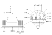
処理液吐出部830は、図3および図4に示すように、X方向に延設されたフロー管831を有している。本実施形態では4本のフロー管831がY方向に互いに離間して配置されている。各フロー管831の(-X)方向端部はフロー配管系839のアウトレットと接続され、(+X)方向端部は封止されている。また、各フロー管831の側壁には複数の処理液吐出口834が一定の間隔でX方向に配列するように穿設されている。本実施形態では、図4に示すように、各処理液吐出口834は(-Z)方向に向けて設けられている。このため、フロー管831に供給されてきた処理液は配管内部を(+X)方向に流れ、各処理液吐出口834から底壁821a、つまり貯留空間821fの内底面821hに向けて吐出される。そして、処理液は図4中の実線矢印で示すように貯留空間821fの内底面821hを経由して上方に流れ、処理槽821の底壁821aから上方開口821g、つまりオーバーフロー面に向う処理液の流れFを形成する。こうして、処理液の上昇流が基板Wの下方側に形成される。なお、発明内容の理解を容易とするため、4本のフロー管831のうち最も(-Y)方向側に配置されたものを「フロー管831a」と称し、(+Y)方向側に順次配置されるものをそれぞれ「フロー管831b」、「フロー管831c」および「フロー管831d」と称する。また、これらを区別しない場合には、上記のように単に「フロー管831」と称する。
As shown in Figures 3 and 4, the treatment
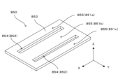
気泡供給部840は、図3ないし図5に示すように、複数(本実施形態では4本)のバブラー841を有している。各バブラー841は、X方向に延設されたバブル配管842と、バブル配管842から上方、つまり(+Z)方向に突設される複数の突設部位843を有している。各バブル配管842の一方端部は窒素ガスを供給するガス供給部844と接続され、他方端部は封止されている。複数の突設部位843は一定の基板ピッチPTと同じピッチPTでバブル配管842の上方側壁に設けられている。各突設部位843は図3に示すように中空円柱形状を有し、上端面の中央部に気泡吐出口845が設けられている。本実施形態では、樹脂材料、特にポリエーテルエーテルケトン(PEEK)、パーフルオロアルコキシアルカン(PFA)、およびポリテトラフルオロエチレン(PTFE)からなる群から選択された少なくとも1つのもので構成された長尺樹脂管の表面に対して切削加工と穿設加工を施すことでバブル配管842と複数の突設部位843とを一体的に形成している。ここで、バブル配管842と、複数の突設部位843とを個別に準備し、バブル配管842に対して複数の突設部位843を取り付けて一体化させてもよいことは言うまでもない。
As shown in Figures 3 to 5, the
このように構成された気泡供給部840では、制御部9からの気泡供給指令に応じてガス供給部844が窒素ガスを気泡供給部840に供給すると、バブル配管842を流れる窒素ガスが気泡吐出口845から上方に向けて吐出する。これによって、窒素ガスの気泡Vが貯留空間821fに貯留された処理液に供給され、鉛直方向Zにおいて処理液吐出口834よりも高い位置からオーバーフロー面に向う方向、つまり(+Z)方向に気泡Vが供給される。これらの気泡Vは処理液中を上昇し、基板Wの表面の処理液を新鮮な処理液に置換することを促進する。なお、ガス供給部844としては、例えば窒素ガスが充填されたボンベから窒素ガスを供給する構成であってもよいし、基板処理システム1が設置される工場に設けられたユーティリティを用いてもよい。
In the
また、図4に示すように、4本のバブラー841は、3つのバブラーボード851により下方から支持されることで、リフタ810aに保持された基板Wの下方側かつ処理液吐出口834の上方側で固定的に配置されている。ここでも、発明内容の理解を容易とするため、4本のバブラー841のうち最も(-Y)方向側に配置されたものを「バブラー841a」と称し、(+Y)方向側に順次配置されるものをそれぞれ「バブラー841b」、「バブラー841c」および「バブラー841d」と称する。また、これらを区別しない場合には、上記のように単に「バブラー841」と称する。一方、バブラーボード851についても同様に、バブラーボード851のうち最も(-Y)方向側に配置されたものを「バブラーボード851a」と称し、(+Y)方向側に順次配置されるものをそれぞれ「バブラーボード851b」および「バブラーボード851c」と称する。また、これらを区別しない場合には、上記のように単に「バブラーボード851」と称する。
4, the four
バブラーボード851a~851cはいずれもX方向に延設されたプレート形状を有している。これらのうちバブラーボード851aは、図4に示すように、鉛直方向Zにおいて処理液吐出口834よりも高い位置でフロー管831aとフロー管831bとの間に配置されるとともに固定部材(図示省略)により処理槽821に固定されている。そして、当該バブラーボード851aの上面にバブラー841aが次の配置関係を満足するように固定されている。その配置関係とは、図5に示すように、バブラー841aに取り付けられた突設部位843が上方を向いていることと、X方向において基板Wと気泡吐出口845とが交互に位置するということである。このように配置することで気泡吐出口845から供給された気泡VはX方向において隣接する基板Wの間に向けて気泡Vを吐出され、効率的な薬液処理が実行される。なお、この配置関係はその他のバブラー841b~841dについても同様である。
The
バブラーボード851bは鉛直方向Zにおいて処理液吐出口834よりも高い位置でフロー管831bとフロー管831cとの間に配置されるとともに固定部材(図示省略)により処理槽821に固定されている。そして、当該バブラーボード851bの上面にバブラー841b、841cがY方向に一定間隔だけ離間しながら固定されている。さらにバブラーボード851cは鉛直方向Zにおいて処理液吐出口834よりも高い位置でフロー管831cとフロー管831dとの間に配置されるとともに固定部材(図示省略)により処理槽821に固定されている。そして、当該バブラーボード851cの上面にバブラー841dが固定されている。このようにバブラーボード851a~851cは気泡供給部840を下方から支持する機能を有している。
The
また、バブラーボード851a~851cは鉛直方向Zにおいて処理液吐出口834よりも高い位置にてフロー管831a~831dの間に配置されているため、上記支持機能以外に、貯留空間821fの内底面821hを経由して上方に流れる処理液の流れFを規制する機能を有している。バブラーボード851a~851cは互いに離間して処理液の流通経路となる貫通部位852a、852bを形成している。そして、貫通部位852a、852bにフロー管831b、831cの下端部が入り込むように配置されている。また、フロー管831b、831cと同一高さ位置で、フロー管831aがバブラーボード851aの(-Y)方向側に配置されるとともにフロー管831dがバブラーボード851aの(+Y)方向側に配置されている。しかも、バブラーボード851a~851cおよびフロー管831a~831dのうち互いに隣接するもの同士の間に隙間86が形成されている。このため、処理液の上昇流のうちバブラーボード851の下面に向かって流れる処理液(以下「分流対象液」という)の流れFは当該下面で規制され、水平面内で振り分けられる。例えば図4の部分拡大図では、バブラーボード851cの下面に向う分流対象液の流れFはバブラーボード851cとフロー管831cとの隙間86を流れる処理液の流れF5とバブラーボード851cとフロー管831dとの隙間86を流れる処理液の流れF6とに分流される。また、他のバブラーボード851a、851bにおいても、バブラーボード851cと同様に、分流対象液の流れFが規制されて複数の処理液の流れF1~F4に分流される。
In addition, the
このように本実施形態では、貯留空間821fの内底面821hを経由して上方に流れる処理液の一部(分流対象液)の流れFが複数の流れF1~F6に分流されてオーバーフロー面に向けて上昇する。このように本実施形態では、バブラーボード851a~851cは貯留空間821fの内底面821hを経由して上方に流れる処理液の少なくとも一部を分流対象液とし、当該分流対象液の流れFを複数の上昇流に分流してリフタ810aに保持された基板Wに案内しており、分流部850(図3)として機能している。
In this embodiment, a flow F of a portion of the processing liquid (liquid to be diverted) flowing upward via the
なお、図2ないし図5を参照しつつ本発明に係る基板処理装置の第1実施形態に相当する第1薬液処理部81の構成について説明したが、第2薬液処理部83も処理液の種類が同種または異種である点を除き、第1薬液処理部81と同一の構成を有し、本発明に係る基板処理装置の第1実施形態に相当している。また、第1リンス処理部82および第2リンス処理部84は、処理液が純水やDIW(deionized water)などのリンス液である点を除き、第1薬液処理部81と同一の構成を有し、本発明に係る基板処理装置の第1実施形態に相当している。
The configuration of the first
以上のように、本実施形態によれば、処理液吐出口834から処理液が貯留空間821fの内底面821hに向けて吐出され、当該内底面821hを経由してオーバーフロー面に向う処理液の流れFを形成している。このため、処理液を基板Wの下方側から上方や斜め上方に向けて吐出したり、特許文献1に記載の装置のように貯留空間の内底面に沿って吐出した従来技術に比べて貯留空間821f内で処理液の上昇流が偏って形成されるのを抑制することができる。しかも、鉛直方向Zにおける気泡供給部840と貯留空間821fの内底面821hとの間で、内底面821hを経由して上方に流れる処理液の流れFの一部については、複数の流れF1~F6に分流した後でオーバーフロー面に向けて案内している。したがって、貯留空間821fに貯留された処理液内では、数多くの上昇流が処理液内で広く分散して形成された状態で処理液は上昇する。このため、貯留空間821f内で下降流が発生するのを効果的に抑制することができる。その結果、基板Wに対して気泡Vが均一に供給され、基板処理を高品質で行うことができる。
As described above, according to this embodiment, the processing liquid is discharged from the processing
特に、第1薬液処理部81は高アスペクト比の凹部を介してSiN膜をウエットエッチングするため、本発明を第1薬液処理部81に適用することは3D-NANDメモリの製造に重要である。すなわち、ウエットエッチング性能を高めるためには凹部の内部と外部との間で処理液の置換を良好に行う必要がある。また、凹部の底付近にエッチング反応に伴うシリコン析出が発生するが、処理液の置換により上記シリコンを凹部から排出することが可能となる。この液置換を安定的かつ継続して発現させるためには、凹部の内部と外部との濃度差、つまり濃度勾配を大きく、しかも基板Wの表面全体にわたって均一に保つ必要がある。さらに言えば、これらを満足させるためには、基板Wの表面に新鮮な処理液を均一に供給することが重要な技術事項となる。この点について、基板Wに対して気泡Vを均一に供給することができる第1薬液処理部81によれば、気泡Vによる処理液の均一供給によりSiN膜のウエットエッチングを良好に行うことができる。
In particular, since the first
また、図4の部分拡大図に示すように、互いに隣接するフロー管831c、831dの間にバブラーボード851cおよびバブラー841dが配置されている。つまり、バブラーボード851cおよびバブラー841dは鉛直方向Zにおいてフロー管831c、831dの最頂部位と最低部位(処理液吐出口834)との間に配置されている。この点については、フロー管831a、831bの間およびフロー管831b、831cの間においても同様である。このように、処理液吐出部830、気泡供給部840および分流部850は鉛直方向Zにおいてフロー管831の外径寸法の範囲に収まっており、鉛直方向Zにおいて処理槽821をサイズアップすることなく、基板処理を高品質で行うことができる。
As shown in the partially enlarged view of FIG. 4, a
また、図4に示すように、貯留空間821f内でリフタ810aに保持された基板Wの中心Wcを通るとともに基板Wの表面と直交する仮想鉛直面VSに対し、処理液吐出部830、気泡供給部840および分流部850が対称配置されている。このため、貯留空間821fに貯留された処理液内で発生する上昇流も仮想鉛直面VSに対して対象となり、上昇流の偏りが抑えられ下降流の発生を効果的に抑制することができる。
As shown in FIG. 4, the processing
また、図5の部分拡大図に示すように、X方向において基板Wと気泡吐出口845とが交互に位置するようにバブラー841dに配置されているため、気泡Vを互いに隣接する基板Wの間に向けて効率的に供給することができる。その結果、基板処理(薬液処理やリンス処理)を高品質で行うことができる。
In addition, as shown in the partially enlarged view of FIG. 5, the
また、バブラーボード851a~851cを気泡供給部840の鉛直直下に位置させて気泡供給部840を下方から支持している。このため、気泡供給部840をしっかりと固定することができ、気泡Vを安定して互いに隣接する基板Wの間に向けて供給することができる。
The
さらに、図3に示すように、貫通部位852a、852bは気泡吐出口845の配列方向Xと平行な方向に設けられている。このため、貫通部位852a、852bを通過して上方に流れる処理液の流れと気泡Vの流れの相対的な関係がX方向において一定となり、気泡Vの供給方向が乱れるのを抑制する。その結果、気泡Vを安定して互いに隣接する基板Wの間に向けて供給することができる。
Furthermore, as shown in FIG. 3, the through-
このように第1実施形態では、バブラーボード851a~851cが本発明の「規制部位」の一例に相当している。また、バブラーボード851a~851cの下面で振り分けられた後に隙間86を流れる処理液が本発明の「前記規制部位を経由して流れ込んで来る前記処理液」に相当している。また、X方向およびY方向がそれぞれ本発明の「第1水平方向」および「第2水平方向」に相当している。
In this way, in the first embodiment, the
図6は本発明に係る基板処理装置の第2実施形態の概略構成を示す部分断面図である。この第2実施形態が第1実施形態と大きく相違する点は、2枚のバブラーボード851の追加と、2つのバブラー841の追加とであり、その他の構成は第1実施形態と同一である。したがって、以下においては、相違点を中心に説明し、同一構成については同一符号を付して説明を省略する。
Figure 6 is a partial cross-sectional view showing the schematic configuration of a second embodiment of a substrate processing apparatus according to the present invention. The main difference between this second embodiment and the first embodiment is the addition of two
第1実施形態では、図4に示すように、内底面821hを経由して処理槽821の側壁821cとフロー管831aとの間に流れ込んできた処理液はそのままオーバーフロー面に向かって上昇し、処理液の流れFを形成する。これに対し、第2実施形態では、処理槽821の側壁821cとフロー管831aとの間にバブラーボード851(これを「バブラーボード851d」と称する)が配置されている。このため、上記処理液は分流対象液に相当し、その流れFはバブラーボード851dの下面で規制されて水平面内で振り分けられる。その結果、分流対象液の流れFは側壁821cおよびバブラーボード851dの隙間を流れる処理液の流れF7とバブラーボード851cおよびフロー管831aとの隙間を流れる処理液の流れF8とに分流される。また、処理槽821の側壁821e側も同様に、処理槽821の側壁821eとフロー管831dとの間にバブラーボード851(これを「バブラーボード851e」と称する)が配置されることで、その間に流れ込んでくる処理液は分流対象液に相当し、その流れFはバブラーボード851eの下面で規制されて水平面内で振り分けられる。その結果、分流対象液の流れFはバブラーボード851eおよびフロー管831dとの隙間を流れる処理液の流れF9と側壁821eおよびバブラーボード851eの隙間を流れる処理液の流れF10とに分流される。
In the first embodiment, as shown in FIG. 4, the treatment liquid flowing into the space between the
このように第2実施形態によれば、第1実施形態のように貯留空間821fの中央部で数多くの上昇流が広く分散して形成されるのみならず、貯留空間821fの端部においても数多くの上昇流が広く分散して形成される。すなわち、内底面821hを経由して上方に流れる処理液の流れFの全部については、複数に分流した後でオーバーフロー面に向けて案内している。このため、貯留空間821f内で下降流が発生するのをさらに効果的に抑制することができる。その結果、基板Wに対して気泡Vが均一に供給され、基板処理をさらに高品質で行うことができる。
As described above, according to the second embodiment, not only are numerous upward flows formed in a widely dispersed manner in the center of the
また、第2実施形態では、バブラーボード851d、851e上にバブラー841を追加設置しているため、気泡Vの供給範囲を広げることができ、基板処理をさらに高品質で行うことができる。
In addition, in the second embodiment, a
図7は本発明に係る基板処理装置の第3実施形態の概略構成を示す平面図であり、図8は本発明に係る基板処理装置の第3実施形態の概略構成を示す断面図である。この第3実施形態が第1実施形態と大きく相違する点は、バブラー841およびバブラーボード851の個数、ならびにフロー管831、バブラー841およびバブラーボード851の相対位置関係であり、その他の構成は第1実施形態と同一である。したがって、以下においては、相違点を中心に説明し、同一構成については同一符号を付して説明を省略する。
Figure 7 is a plan view showing a schematic configuration of a third embodiment of a substrate processing apparatus according to the present invention, and Figure 8 is a cross-sectional view showing a schematic configuration of the third embodiment of a substrate processing apparatus according to the present invention. The third embodiment differs significantly from the first embodiment in the number of
第3実施形態では、貯留空間821fの内底面821hの直上位置で4本のフロー管831がX方向に互いに離間した状態で配置されている。各フロー管831はY方向に延設され、処理液吐出口834を内底面821hに向けた姿勢で配置されている。また、フロー管831の直上位置で複数本(第3実施形態では8本)のバブラーボード851がY方向に互いに離間した状態で配置されている。各バブラーボード851はX方向に延設されている。このため、フロー管831とバブラーボード851とは互いに直交しており、上方からの平面視で格子構造が形成されている。このため、フロー管831の処理液吐出口834から吐出された処理液は内底面821hを経由して隣接するフロー管831の間を通過して上方に流れる。この処理液の一部(分流対象液)はバブラーボード851の下面で規制されて水平面内で振り分けられ、平面視でフロー管831およびバブラーボード851のいずれも存在していない貫通部位852を通過してオーバーフロー面に向けて上昇する。このように、第1実施形態や第2実施形態と同様に、分流対象液の流れはバブラーボード851により複数に分流される。その結果、第1実施形態や第2実施形態と同様の作用効果が得られる。
In the third embodiment, four
また、各バブラーボード851上にはバブラー841が固定されているが、バブラー841の気泡吐出口845と基板Wとの配置関係は第1実施形態や第2実施形態と同様であり、気泡Vを互いに隣接する基板Wの間に向けて効率的に供給することができる。その結果、基板処理(薬液処理やリンス処理)を高品質で行うことができる。
In addition, a
ところで、第1実施形態および第2実施形態では、分流部850を構成するバブラーボード851を隣接するフロー管831の間に配置しているが、第3実施形態と同様に、フロー管831の直上位置でバブラーボード851を配置し、さらに当該バブラーボード851上にバブラー841を配置してもよい(第4実施形態)。
In the first and second embodiments, the
また、第1実施形態ないし第4実施形態では、独立した3枚のバブラーボード851を互いに離間させつつY方向に配列して分流部850を構成しているが、分流部850の構成はこれに限定されるのではなく、例えば図9に示すように構成してもよい(第5実施形態)。
In addition, in the first to fourth embodiments, the
図9は本発明に係る基板処理装置の第5実施形態で用いている分流部の構成を模式的に示す図である。この第5実施形態では、1枚のプレート部材853に対してX方向に延びるスリット854をY方向に離間して設けたものを分流部850として用いてもいる。この第5実施形態では、スリット854が貫通部位852として機能するとともに、スリット854により分離された各帯状領域855がバブラーボード851として機能し、上記実施形態と同様の作用効果が得られる。
Figure 9 is a schematic diagram showing the configuration of a flow dividing section used in a fifth embodiment of a substrate processing apparatus according to the present invention. In this fifth embodiment, a
また、第3実施形態および第4実施形態では、フロー管831の直上位置で独立した複数のバブラーボード851を互いに離間させつつY方向に配列して分流部850を構成しているが、例えば図10に示すように構成してもよい(第6実施形態)。
In the third and fourth embodiments, the
図10は本発明に係る基板処理装置の第6実施形態で用いている分流部の構成を模式的に示す図である。この第6実施形態では、プレート部材853に対してスリット854を設ける代わりに、同図に示すようにプレート部材853に複数の貫通孔856が穿設されている。すなわち、第6実施形態では、貫通孔群が実質的に貫通部位852として機能するとともに、当該貫通孔群により分離された各帯状領域855がバブラーボード851として機能し、上記実施形態と同様の作用効果が得られる。
Figure 10 is a diagram showing a schematic configuration of a flow dividing section used in a sixth embodiment of a substrate processing apparatus according to the present invention. In this sixth embodiment, instead of providing a
また、上記実施形態では、バブラー841を分流部850のバブラーボード851により支持して貯留空間821fに貯留された処理液内で固定的に配置するとともに、当該バブラーボード851により内底面821hを経由して上方に流れる処理液の流れFを複数の流れに分流させている。ここで、例えばバブラーボード851を処理槽821に直接的に固定する場合、例えば図11に示すように隣接するフロー管831の間にバブラー841を配置してもよい(第7実施形態)。
In the above embodiment, the
図11は本発明に係る基板処理装置の第7実施形態の概略構成を示す断面図である。この第7実施形態では、同図に示すように、フロー管831の処理液吐出口834から吐出された処理液は内底面821hを経由して隣接するフロー管831の間を通過して上方に流れる。この処理液の一部(分流対象液)はバブラー841のバブル配管842の下面で規制されて水平面内で振り分けられ、オーバーフロー面に向けて上昇する。このように、分流対象液の流れはバブラー841により複数に分流される。その結果、第1実施形態や第2実施形態と同様の作用効果が得られる。また、分流部850が省略される分だけ装置を簡素化することができる。
Figure 11 is a cross-sectional view showing a schematic configuration of a seventh embodiment of a substrate processing apparatus according to the present invention. In this seventh embodiment, as shown in the figure, the processing liquid discharged from the processing
また、上記実施形態では、内底面821hを経由して上方に流れる処理液の一部または全部を分流対象液とし、分流対象液の流れを分流して下降流の発生を抑制している。これに加え、別の下降流の発生を抑制するための構成を追加してもよい。例えば図12に示すように、処理槽821に側壁開口821h~821kが設けてもよい(第8実施形態)。
In the above embodiment, a part or all of the treatment liquid flowing upward via the
図12は本発明に係る基板処理装置の第8実施形態で用いている処理槽の構成を示す図である。第8実施形態が第1実施形態(図3)と大きく相違する点は、処理槽821の全側壁821b~821eにおいて処理液に浸漬されている基板Wと対向する基板対向領域に側壁開口821h~821kが設けられている点であり、その他の構成は第1実施形態と同一である。したがって、以下においては、相違点を中心に説明し、同一構成については同一符号を付して説明を省略する。
Figure 12 is a diagram showing the configuration of a processing tank used in an eighth embodiment of a substrate processing apparatus according to the present invention. The eighth embodiment differs significantly from the first embodiment (Figure 3) in that
第8実施形態では、側壁開口821h~821kによって貯留空間821fと回収空間822aとが連通される。このため、上方開口821gに向かって流れる処理液は上方開口821gを介してオーバーフローして処理槽821から回収空間822aに排出されるものと側壁開口821h~821kを介して処理槽821から回収空間822aに排出されるものとに分流される。このようにオーバーフロー面に近い位置での処理液の分流によって下降流はさらに効果的に抑制され、基板Wに対して気泡Vをさらに均一に供給することができる。その結果、基板処理をさらに高品質で行うことができる。
In the eighth embodiment, the
また、下降流の発生をさらに抑制するために、特開平11-102888号公報に記載された技術、つまり上方開口821gの面積を制限するカバーを追加して下降流を抑制するという技術を上記実施形態に付加してもよい。
In addition, to further suppress the occurrence of downward flow, the technology described in JP 11-102888 A, that is, the technology of suppressing downward flow by adding a cover that limits the area of the
なお、本発明は上記した実施形態に限定されるものではなく、その趣旨を逸脱しない限りにおいて上述したもの以外に種々の変更を行うことが可能である。例えば上記実施形態では、バブル配管842から中空円柱状の突設部位843を設けたバブラー841を用いて気泡Vを供給しているが、バブラー841の構成はこれに限定されるものではない。例えば図13に示すように中空円錐台形状の突設部位846をバブル配管842から突設したものを用いてもよい(第9実施形態)。また、例えば図14に示すように突設部位を設けないもの、つまりバブル配管842の上面に気泡吐出口845を穿設したものを用いてもよい(第10実施形態)。
The present invention is not limited to the above-mentioned embodiment, and various modifications can be made without departing from the spirit of the invention. For example, in the above-mentioned embodiment, bubbles V are supplied using a
また、上記実施形態では、処理液吐出部830は4本のフロー管831を含んでいるが、フロー管831の本数はこれに限定されるものではなく、貯留空間821fや基板Wのサイズ等に応じて設定するのが望ましい。また、気泡供給部840に含まれるバブラー841の本数は4本(第1実施形態、第7実施形態など)、6本(第2実施形態)、8本(第3実施形態)であるが、バブラー841の本数はこれらに限定されるものではなく、貯留空間821fや基板Wのサイズ等に応じて設定するのが望ましい。また、分流部850に含まれるバブラーボード851の枚数は3枚(第1実施形態、第7実施形態など)、5枚(第2実施形態)、8枚(第3実施形態)であるが、バブラー841の本数はこれらに限定されるものではなく、貯留空間821fや基板Wのサイズ等に応じて設定するのが望ましい。
In the above embodiment, the processing
また、上記実施形態では、例えば図4などに示すように、処理液吐出口834は貯留空間821fの内底面821hに向けて開口されており、処理液は内底面821hに吐出される。ここで、処理液を内底面821hに流通させる手段はこれに限定されるものではない(例えば第11実施形態や第12実施形態)。
In the above embodiment, as shown in FIG. 4, for example, the treatment
図15は本発明に係る基板処理装置の第11実施形態の主要構成を部分的に示す分解組立斜視図である。図16は第11実施形態に係る基板処理装置の部分断面図である。この第11実施形態が第1実施形態(図4)と大きく相違する点は、フロー管831の本数および配置と、カバー部材835の追加と、貫通部位852として機能するスリット857のバブラーボード851への追加とであり、その他の構成は基本的に第1実施形態と同一である。したがって、以下においては、相違点を中心に説明し、同一構成については同一符号を付して説明を省略する。
Figure 15 is an exploded perspective view partially showing the main configuration of an eleventh embodiment of a substrate processing apparatus according to the present invention. Figure 16 is a partial cross-sectional view of the substrate processing apparatus according to the eleventh embodiment. The eleventh embodiment differs significantly from the first embodiment (Figure 4) in the number and arrangement of
第11実施形態では、フロー管831は従来装置と同様に配置されている。つまり、フロー管831は、その処理液吐出口834を図示省略するリフター(基板保持部)に保持された基板Wの下方端部に向けて開口されている。このため、制御部9からの処理液供給指令に応じて処理液供給部832が作動すると、処理液が図16の拡大図中の矢印AR1で示すように基板Wに向けてはフロー管831から吐出される。ただし、本実施形態では、フロー管831を上方から覆うようにカバー部材835が配置され、同図中の矢印AR2で示すように上記処理液を貯留空間821fの内底面821hに向けて案内する。これによって、第1実施形態ないし第10実施形態と同様に、処理液は内底面821hを経由して上方に流れる。つまり、分流対象液が形成される。分流対象液の一部はバブラーボード851の下面で規制され、水平面内で振り分けられる。そして、振り分けられた処理液がバブラーボード851のスリット857(貫通部位852)を通過してオーバーフロー面に向けて上昇する。こうして、上記実施形態と同様に、分流対象液の流れはバブラーボード851により複数に分流される。その結果、貯留空間821f内で下降流が発生するのを効果的に抑制し、基板処理を高品質で行うことが可能となる。
In the eleventh embodiment, the
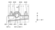
上記第11実施形態では、カバー部材835を設けたことでカバー部材835の直上における処理液の流れが少なくなる傾向にある。そこで、図17に示すようにカバー部材835の一部に貫通孔836を設け、カバー部材835の直上においても処理液の一部を送り込むように構成してもよい(第12実施形態)。
In the eleventh embodiment, the provision of the
図17は本発明に係る基板処理装置の第12実施形態の部分断面図である。この第12実施形態では、貫通孔836が処理液吐出口834と対向しない位置でカバー部材835に設けられている。このため、処理液吐出口834から吐出された処理液はカバー部材835の湾曲下面に沿って流れ、その一部が貫通孔836を通過してカバー部材835から基板Wの下方端部に向けて流通する(同図の矢印F0参照)。一方、それ以外の処理液は第11実施形態と同様に分流対象液となり、一部はバブラーボード851の下面で規制され、水平面内で振り分けられる。このようにカバー部材835の直上領域に対して処理液の流れF0を追加することで、貯留空間821f内で下降流が発生するのをさらに効果的に抑制することができる。その結果、基板Wに対する気泡Vの供給均一性を高め、基板処理をさらに高品質で行うことができる。
17 is a partial cross-sectional view of a twelfth embodiment of the substrate processing apparatus according to the present invention. In this twelfth embodiment, a through
また、上記実施形態では、窒素ガスをバブラー841に送り込んで気泡Vを処理液内に供給しているが、窒素ガス以外のガスを本発明の「気体」として用いてもよい。
In addition, in the above embodiment, nitrogen gas is sent to the
さらに、上記実施形態では、リン酸を含む薬液により薬液処理を行う基板処理装置やリンス処理を行う基板処理装置に対して本発明を適用しているが、本発明の適用範囲はこれに限定されるものではなく、上記薬液やリンス液以外の処理液に基板を浸漬させて基板処理を行う基板処理技術全般に本発明を適用することができる。 Furthermore, in the above embodiment, the present invention is applied to a substrate processing apparatus that performs chemical processing using a chemical solution containing phosphoric acid and a substrate processing apparatus that performs rinsing processing, but the scope of application of the present invention is not limited to this, and the present invention can be applied to substrate processing techniques in general that perform substrate processing by immersing a substrate in a processing solution other than the above chemical solutions and rinsing solutions.
この発明は、処理液を処理槽からオーバーフローさせながら処理槽に貯留された処理液に基板を浸漬するとともに処理液中で上記基板に気泡を供給して処理する基板処理技術全般に適用することができる。 This invention can be applied to the general substrate processing technology in which a substrate is immersed in a processing liquid stored in a processing tank while the processing liquid is allowed to overflow from the processing tank, and air bubbles are supplied to the substrate in the processing liquid.
81…第1薬液処理部(基板処理装置)
82…第1リンス処理部(基板処理装置)
83…第2薬液処理部(基板処理装置)
84…第2リンス処理部(基板処理装置)
810,810a,810b…リフタ(基板保持部)
821…処理槽
821a…(処理槽の)底壁
821b~821e…(処理槽の)側壁
821f…貯留空間
821g…上方開口
821h…(貯留空間の)内底面
821h~821k…側壁開口
822…オーバーフロー槽
822a…回収空間
830…処理液吐出部
831,831a~831d…フロー管
834…処理液吐出口
835…カバー部材
836…貫通孔
840…気泡供給部
841,841a~841d…バブラー
845…気泡吐出口
850…分流部
851,851a~851e…バブラーボード
852,852a,852b…貫通部位
V…気泡
VS…仮想鉛直面
W…基板
Wc…(基板の)中心
X…第1水平方向
Y…第2水平方向
Z…鉛直方向
81...First chemical processing unit (substrate processing apparatus)
82: First rinse processing unit (substrate processing apparatus)
83: Second chemical processing unit (substrate processing apparatus)
84: Second rinse processing unit (substrate processing apparatus)
810, 810a, 810b... Lifter (substrate holding part)
821...
Claims (18)
前記貯留空間内で前記基板を起立姿勢で保持する基板保持部と、
前記基板保持部に保持された前記基板の下方側で前記処理液を吐出する処理液吐出口を有し、前記処理液吐出口から吐出された前記処理液を前記貯留空間の内底面に向かって流す処理液吐出部と、
前記基板保持部に保持された前記基板の下方側かつ前記処理液吐出口の上方側に設けられ、前記貯留空間に貯留された前記処理液に気泡を供給する気泡供給部と、
鉛直方向における前記気泡供給部と前記貯留空間の内底面との間で、前記貯留空間の内底面を経由して上方に流れる前記処理液の少なくとも一部を分流対象液とし、前記分流対象液の流れを複数の上昇流に分流する分流部と、を備え、
前記分流部は、
前記分流対象液の上方への流れを規制して前記分流対象液を水平面内で振り分ける規制部位と、
水平面内で前記規制部位に隣接しながら鉛直方向に貫通して設けられ、前記規制部位を経由して流れ込んで来る前記処理液を前記基板保持部に保持された前記基板に向けて案内する複数の貫通部位とを有し、
前記分流対象液の流れを前記規制部位により複数の上昇流に分流し、前記貫通部位を介して前記基板保持部に保持された前記基板に案内することを特徴とする基板処理装置。 a processing tank having a storage space for storing a processing liquid, the processing liquid being allowed to overflow from an upper opening of the storage space while the substrate is processed by immersing the substrate in the processing liquid stored in the storage space;
a substrate holder that holds the substrate in an upright position within the storage space;
a processing liquid discharge unit having a processing liquid discharge port that discharges the processing liquid below the substrate held by the substrate holding unit, and causes the processing liquid discharged from the processing liquid discharge port to flow toward an inner bottom surface of the storage space;
a bubble supply unit provided below the substrate held by the substrate holder and above the treatment liquid discharge port, the bubble supply unit supplying bubbles to the treatment liquid stored in the storage space ;
a diversion section which divides at least a part of the treatment liquid flowing upward via the inner bottom surface of the storage space into a plurality of upward flows between the air bubble supply section and the inner bottom surface of the storage space in the vertical direction, and divides the flow of the diversion liquid into a plurality of upward flows ,
The flow dividing section is
a regulating portion that regulates an upward flow of the liquid to be divided and distributes the liquid to be divided within a horizontal plane;
a plurality of through-portions that are adjacent to the regulating portion in a horizontal plane and penetrate the substrate in a vertical direction, and that guide the processing liquid that flows in through the regulating portion toward the substrate held by the substrate holding portion;
a restricting portion for dividing the flow of the liquid to be divided into a plurality of ascending flows , and the divided flows are guided to the substrate held by the substrate holding portion via the penetrating portion .
前記処理液吐出部は、第1水平方向に延設されるとともに側壁に前記処理液吐出口が複数個前記第1水平方向に配列して設けられる、複数のフロー管を有し、
前記複数のフロー管が前記第1水平方向と直交する第2水平方向に互いに離間して配置されるとともに、前記第2水平方向において互いに隣接する前記フロー管の間に前記規制部位が配置される基板処理装置。 The substrate processing apparatus according to claim 1 ,
the treatment liquid discharge unit includes a plurality of flow pipes extending in a first horizontal direction and having a plurality of treatment liquid discharge ports arranged in a side wall of the flow pipes in the first horizontal direction;
The substrate processing apparatus, wherein the plurality of flow tubes are disposed spaced apart from one another in a second horizontal direction perpendicular to the first horizontal direction, and the regulating portion is disposed between the flow tubes adjacent to one another in the second horizontal direction.
前記第2水平方向において互いに隣接する前記フロー管と前記処理槽との間に前記規制部位がさらに配置される基板処理装置。 The substrate processing apparatus according to claim 2 ,
The substrate processing apparatus further includes the regulating portion disposed between the flow pipe and the processing bath adjacent to each other in the second horizontal direction.
前記基板保持部は複数の前記基板を第1水平方向に互いに離間しながら保持し、
前記気泡供給部は、前記第1水平方向に延設されるとともに側壁に前記気泡を吐出する気泡吐出口が複数個前記第1水平方向に配列して設けられる、複数のバブラーを有し、
前記第1水平方向において前記基板と前記気泡吐出口とが交互に位置し、
前記気泡吐出口の各々は前記第1水平方向において隣接する前記基板の間に向けて前記気泡を吐出する基板処理装置。 3. The substrate processing apparatus according to claim 1 ,
the substrate holder holds the substrates while separating them from one another in a first horizontal direction;
the air bubble supply unit includes a plurality of bubblers extending in the first horizontal direction and including a plurality of air bubble outlets arranged in a side wall in the first horizontal direction, the air bubble outlets discharging the air bubbles;
the substrate and the bubble discharge port are alternately positioned in the first horizontal direction,
The substrate processing apparatus includes: a first nozzle configured to discharge the bubbles toward a gap between the substrates adjacent to each other in the first horizontal direction;
前記規制部位は第1水平方向に延設され、
前記処理液吐出部は、前記第1水平方向と直交する第2水平方向に延設されるとともに側壁に前記処理液吐出口が複数個前記第2水平方向に配列して設けられる、複数のフロー管を有する基板処理装置。 The substrate processing apparatus according to claim 1 ,
The restriction portion extends in a first horizontal direction,
The processing liquid discharge section is a substrate processing apparatus having a plurality of flow pipes extending in a second horizontal direction perpendicular to the first horizontal direction and having a plurality of processing liquid discharge ports arranged in an array in the second horizontal direction on the side walls.
前記基板保持部は複数の前記基板を前記第1水平方向に互いに離間しながら保持し、
前記気泡供給部は、前記第1水平方向に延設されるとともに側壁に前記気泡を吐出する気泡吐出口が複数個前記第1水平方向に配列して設けられる、複数のバブラーを有し、
前記第1水平方向において前記基板と前記気泡吐出口とが交互に位置し、
前記気泡吐出口の各々は前記第1水平方向において隣接する前記基板の間に向けて前記気泡を吐出する基板処理装置。 The substrate processing apparatus according to claim 5 ,
the substrate holding portion holds the plurality of substrates while being spaced apart from one another in the first horizontal direction;
the air bubble supply unit includes a plurality of bubblers extending in the first horizontal direction and including a plurality of air bubble outlets arranged in a side wall in the first horizontal direction, the air bubble outlets discharging the air bubbles;
the substrate and the bubble discharge port are alternately positioned in the first horizontal direction,
The substrate processing apparatus includes: a first nozzle configured to discharge the bubbles toward a gap between the substrates adjacent to each other in the first horizontal direction;
前記規制部位は前記気泡供給部の鉛直直下に位置して前記気泡供給部を下方から支持する基板処理装置。 7. The substrate processing apparatus according to claim 1 ,
The regulating portion is located directly below the air bubble supplying portion and supports the air bubble supplying portion from below.
前記貫通部位は前記気泡吐出口の配列方向と平行な方向に延設される基板処理装置。 7. The substrate processing apparatus according to claim 4 ,
The through-hole extends in a direction parallel to an arrangement direction of the bubble discharge ports.
前記貯留空間内で前記基板を起立姿勢で保持する基板保持部と、
前記基板保持部に保持された前記基板の下方側で前記処理液を吐出する処理液吐出口を有し、前記処理液吐出口から吐出された前記処理液を前記貯留空間の内底面に向かって流す処理液吐出部と、
前記基板保持部に保持された前記基板の下方側かつ前記処理液吐出口の上方側に設けられ、前記貯留空間に貯留された前記処理液に気泡を供給する気泡供給部と、を備え、
前記処理液吐出部は、第1水平方向に延設されるとともに側壁に前記処理液吐出口が複数個前記第1水平方向に配列して設けられる、複数のフロー管を有し、
前記気泡供給部は、前記第1水平方向に延設されるとともに側壁に前記気泡を吐出する気泡吐出口が複数個前記第1水平方向に配列して設けられるバブラーを有し、
前記バブラーは、前記第1水平方向と直交する第2水平方向において互いに隣接する前記フロー管の間に配置され、隣接する前記フロー管の間を流れる前記処理液の少なくとも一部を分流対象液とし、前記分流対象液の流れを複数の上昇流に分流して前記基板保持部に保持された前記基板に案内することを特徴とする基板処理装置。 a processing tank having a storage space for storing a processing liquid, the processing liquid being allowed to overflow from an upper opening of the storage space while the substrate is processed by immersing the substrate in the processing liquid stored in the storage space;
a substrate holder that holds the substrate in an upright position within the storage space;
a processing liquid discharge unit having a processing liquid discharge port that discharges the processing liquid below the substrate held by the substrate holding unit, and causes the processing liquid discharged from the processing liquid discharge port to flow toward an inner bottom surface of the storage space;
a bubble supply unit that is provided below the substrate held by the substrate holding unit and above the processing liquid discharge port, and that supplies bubbles to the processing liquid stored in the storage space,
the treatment liquid discharge unit includes a plurality of flow pipes extending in a first horizontal direction and having a plurality of treatment liquid discharge ports arranged in a side wall of the flow pipes in the first horizontal direction;
the air bubble supply unit includes a bubbler extending in the first horizontal direction and having a side wall with a plurality of air bubble discharge ports arranged in the first horizontal direction for discharging the air bubbles;
The bubbler is disposed between adjacent flow tubes in a second horizontal direction perpendicular to the first horizontal direction, and at least a portion of the processing liquid flowing between the adjacent flow tubes is treated as a diversion target liquid, and the flow of the diversion target liquid is divided into a plurality of upward flows and guided to the substrate held by the substrate holding portion .
前記貯留空間内で前記基板保持部に保持された前記基板の中心を通るとともに前記基板の表面と直交する仮想鉛直面に対し、前記処理液吐出部および前記気泡供給部は対称配置される基板処理装置。 10. The substrate processing apparatus according to claim 1 ,
The substrate processing apparatus, wherein the processing liquid discharge unit and the bubble supply unit are symmetrically disposed with respect to a virtual vertical plane that passes through the center of the substrate held by the substrate holding unit in the storage space and is perpendicular to the surface of the substrate.
前記貯留空間内で前記基板保持部に保持された前記基板の中心を通るとともに前記基板の表面と直交する仮想鉛直面に対し、前記処理液吐出部、前記気泡供給部および前記分流部は対称配置される基板処理装置。 9. The substrate processing apparatus according to claim 1 ,
A substrate processing apparatus, in which the processing liquid discharge unit, the bubble supply unit and the diversion unit are arranged symmetrically with respect to a virtual vertical plane that passes through the center of the substrate held by the substrate holding unit in the storage space and is perpendicular to the surface of the substrate.
前記処理槽の側壁のうち前記上方開口の近傍領域に側壁開口が設けられ、
前記上方開口に向かって流れる前記処理液を、前記上方開口を介してオーバーフローするものと前記側壁開口を介して前記処理槽から排出されるものとに分流する基板処理装置。 The substrate processing apparatus according to claim 1 ,
a side wall opening is provided in a region of the side wall of the treatment tank adjacent to the upper opening;
The substrate processing apparatus divides the processing liquid flowing toward the upper opening into one that overflows via the upper opening and one that is discharged from the processing tank via the side wall opening.
前記処理液吐出口は前記貯留空間の内底面に向けて開口されている基板処理装置。 The substrate processing apparatus according to claim 1 ,
The processing liquid discharge port is open toward an inner bottom surface of the storage space.
前記貯留空間内で前記基板を起立姿勢で保持する基板保持部と、
前記基板保持部に保持された前記基板の下方側で前記処理液を吐出する処理液吐出口を有し、前記処理液吐出口から吐出された前記処理液を前記貯留空間の内底面に向かって流す処理液吐出部と、
前記基板保持部に保持された前記基板の下方側かつ前記処理液吐出口の上方側に設けられ、前記貯留空間に貯留された前記処理液に気泡を供給する気泡供給部と、を備え、
前記処理液吐出口は前記基板保持部に保持された前記基板に向けて開口され、
前記処理液吐出部は、前記処理液吐出口から吐出された前記処理液を前記貯留空間の内底面に向けて案内するカバー部材を有し、
鉛直方向における前記気泡供給部と前記貯留空間の内底面との間で、前記貯留空間の内底面を経由して上方に流れる前記処理液の少なくとも一部を分流対象液とし、
前記分流対象液の流れを複数の上昇流に分流して前記基板保持部に保持された前記基板に案内することを特徴とする基板処理装置。 a processing tank having a storage space for storing a processing liquid, the processing liquid being allowed to overflow from an upper opening of the storage space while the substrate is processed by immersing the substrate in the processing liquid stored in the storage space;
a substrate holder that holds the substrate in an upright position within the storage space;
a processing liquid discharge unit having a processing liquid discharge port that discharges the processing liquid below the substrate held by the substrate holding unit, and causes the processing liquid discharged from the processing liquid discharge port to flow toward an inner bottom surface of the storage space;
a bubble supply unit that is provided below the substrate held by the substrate holding unit and above the processing liquid discharge port, and that supplies bubbles to the processing liquid stored in the storage space,
the processing liquid discharge port is opened toward the substrate held by the substrate holding part,
the treatment liquid discharge unit has a cover member that guides the treatment liquid discharged from the treatment liquid discharge port toward an inner bottom surface of the storage space,
at least a part of the treatment liquid flowing upward via the inner bottom surface of the storage space between the air bubble supply portion and the inner bottom surface of the storage space in the vertical direction is set as a liquid to be diverted;
a substrate processing apparatus for dividing the flow of the liquid to be divided into a plurality of ascending flows and guiding the divided flows to the substrate held by the substrate holding portion .
前記カバー部材は前記処理液吐出口から吐出された前記処理液の一部を前記基板保持部に保持された前記基板に向けて流通させる貫通孔を有する基板処理装置。 The substrate processing apparatus according to claim 14 ,
The cover member has a through hole through which a portion of the processing liquid discharged from the processing liquid discharge port flows toward the substrate held by the substrate holding part.
前記貯留空間に貯留された前記処理液に基板を浸漬させる浸漬工程と、
前記貯留空間内の前記処理液に浸漬された前記基板の下方側より気泡供給部から気泡を供給する気泡供給工程と、を備え、
前記オーバーフロー工程は、前記浸漬工程および前記気泡供給工程と並行して行われ、前記気泡供給部と前記貯留空間の内底面との間で前記貯留空間の内底面を経由して上方に流れる前記処理液の流れの少なくとも一部を分流対象液とし、前記分流対象液の上方への流れを規制して前記分流対象液を水平面内で振り分ける規制部位と、水平面内で前記規制部位に隣接しながら鉛直方向に貫通して設けられ、前記規制部位を経由して流れ込んで来る前記処理液を前記基板に向けて案内する複数の貫通部位とを有する分流部により、前記分流対象液の流れを複数の上昇流に分流して前記基板に案内する
ことを特徴とする基板処理方法。 an overflow process in which the treatment liquid is discharged toward an inner bottom surface of a storage space provided in the treatment tank to store the treatment liquid in the storage space and cause the treatment liquid to overflow from an upper opening of the storage space;
an immersion step of immersing a substrate in the treatment liquid stored in the storage space;
a bubble supplying step of supplying bubbles from a bubble supplying unit from below the substrate immersed in the treatment liquid in the storage space,
the overflow step is performed in parallel with the immersion step and the bubble supply step, and at least a part of the flow of the processing liquid flowing upward via the inner bottom surface of the storage space between the bubble supply unit and the inner bottom surface of the storage space is treated as a diverted liquid, and the flow of the diverted liquid is diverted into a plurality of ascending flows and guided to the substrate by a diverting unit having a regulating portion that regulates the upward flow of the diverted liquid and distributes the diverted liquid in a horizontal plane, and a plurality of through portions that are adjacent to the regulating portion in the horizontal plane and penetrate the regulating portion in the vertical direction, and guide the processing liquid flowing in via the regulating portion toward the substrate.
前記貯留空間に貯留された前記処理液に対し、基板保持部に保持された基板を浸漬させる浸漬工程と、
前記貯留空間内の前記処理液に浸漬された前記基板の下方側より気泡供給部から気泡を供給する気泡供給工程と、を備え、
前記処理液吐出部は、第1水平方向に延設されるとともに側壁に処理液吐出口が複数個前記第1水平方向に配列して設けられる、複数のフロー管を有し、
前記気泡供給部は、前記第1水平方向に延設されるとともに側壁に前記気泡を吐出する気泡吐出口が複数個前記第1水平方向に配列して設けられるバブラーを有し、
前記バブラーは、前記第1水平方向と直交する第2水平方向において互いに隣接する前記フロー管の間に配置され、
前記オーバーフロー工程は、前記浸漬工程および前記気泡供給工程と並行して行われ、鉛直方向における前記気泡供給部と前記貯留空間の内底面との間で、前記貯留空間の内底面を経由して上方に流れる前記処理液の少なくとも一部を分流対象液とし、
隣接する前記フロー管の間を流れる前記分流対象液の流れを複数の上昇流に分流して前記基板保持部に保持された前記基板に案内することを特徴とする基板処理方法。 an overflow process in which the processing liquid is discharged from a processing liquid discharge part into a storage space provided in the processing tank, thereby storing the processing liquid in the storage space, and the processing liquid is caused to overflow from an upper opening of the storage space;
an immersion step of immersing the substrate held by a substrate holder in the processing liquid stored in the storage space;
a bubble supplying step of supplying bubbles from a bubble supplying unit from below the substrate immersed in the treatment liquid in the storage space,
the treatment liquid discharge unit includes a plurality of flow pipes extending in a first horizontal direction and each of which has a side wall on which a plurality of treatment liquid discharge ports are arranged in the first horizontal direction;
the air bubble supply unit has a bubbler extending in the first horizontal direction and having a side wall with a plurality of air bubble discharge ports arranged in the first horizontal direction to discharge the air bubbles;
the bubbler is disposed between adjacent flow tubes in a second horizontal direction perpendicular to the first horizontal direction,
the overflow step is performed in parallel with the immersion step and the bubble supply step, and at least a part of the treatment liquid flowing upward via the inner bottom surface of the storage space between the bubble supply part and the inner bottom surface of the storage space in the vertical direction is treated as a diversion target liquid;
a flow of the liquid to be divided, which flows between adjacent flow pipes , divided into a plurality of ascending flows and guided to the substrate held by the substrate holder.
前記貯留空間に貯留された前記処理液に対し、基板保持部に保持された基板を浸漬させる浸漬工程と、
前記貯留空間内の前記処理液に浸漬された前記基板の下方側より気泡供給部から気泡を供給する気泡供給工程と、を備え、
前記処理液吐出口は前記基板保持部に保持された前記基板に向けて開口され、
前記処理液吐出部は、前記処理液吐出口から吐出された前記処理液を前記貯留空間の内底面に向けて案内するカバー部材を有し、
前記オーバーフロー工程は、前記浸漬工程および前記気泡供給工程と並行して行われ、前記気泡供給部と前記貯留空間の内底面との間で、前記カバー部材および前記貯留空間の内底面の順序で経由して上方に流れる前記処理液の流れの少なくとも一部を複数の上昇流に分流して前記基板に案内する
ことを特徴とする基板処理方法。 an overflow process in which the processing liquid is discharged from a processing liquid discharge port of a processing liquid discharge unit into a storage space provided in a processing tank, thereby storing the processing liquid in the storage space and causing the processing liquid to overflow from an upper opening of the storage space;
an immersion step of immersing the substrate held by a substrate holder in the processing liquid stored in the storage space;
a bubble supplying step of supplying bubbles from a bubble supplying unit from below the substrate immersed in the treatment liquid in the storage space,
the processing liquid discharge port is opened toward the substrate held by the substrate holding part,
the treatment liquid discharge unit has a cover member that guides the treatment liquid discharged from the treatment liquid discharge port toward an inner bottom surface of the storage space,
the overflow step is performed in parallel with the immersion step and the bubble supply step, and at least a portion of the flow of the processing liquid flowing upward between the bubble supply section and the inner bottom surface of the storage space , passing through the cover member and the inner bottom surface of the storage space in that order, is diverted into a plurality of upward flows and guided to the substrate.
Priority Applications (5)
| Application Number | Priority Date | Filing Date | Title |
|---|---|---|---|
| CN202080089352.2A CN114902380B (en) | 2019-12-26 | 2020-12-24 | Substrate processing apparatus and substrate processing method |
| KR1020227019487A KR102666260B1 (en) | 2019-12-26 | 2020-12-24 | Substrate processing device and substrate processing method |
| PCT/JP2020/048378 WO2021132443A1 (en) | 2019-12-26 | 2020-12-24 | Substrate processing device and substrate processing method |
| US17/788,142 US12308258B2 (en) | 2019-12-26 | 2020-12-24 | Substrate processing apparatus and substrate processing method |
| TW109146231A TWI792129B (en) | 2019-12-26 | 2020-12-25 | Substrate processing apparatus and substrate processing method |
Applications Claiming Priority (2)
| Application Number | Priority Date | Filing Date | Title |
|---|---|---|---|
| JP2019236759 | 2019-12-26 | ||
| JP2019236759 | 2019-12-26 |
Publications (2)
| Publication Number | Publication Date |
|---|---|
| JP2021106254A JP2021106254A (en) | 2021-07-26 |
| JP7561539B2 true JP7561539B2 (en) | 2024-10-04 |
Family
ID=76918967
Family Applications (1)
| Application Number | Title | Priority Date | Filing Date |
|---|---|---|---|
| JP2020136163A Active JP7561539B2 (en) | 2019-12-26 | 2020-08-12 | SUBSTRATE PROCESSING APPARATUS AND SUBSTRATE PROCESSING METHOD |
Country Status (2)
| Country | Link |
|---|---|
| JP (1) | JP7561539B2 (en) |
| TW (1) | TWI792129B (en) |
Families Citing this family (6)
| Publication number | Priority date | Publication date | Assignee | Title |
|---|---|---|---|---|
| JP7716349B2 (en) * | 2022-01-28 | 2025-07-31 | 株式会社Screenホールディングス | Substrate Processing Equipment |
| JP7731837B2 (en) * | 2022-03-22 | 2025-09-01 | キオクシア株式会社 | Substrate processing apparatus, substrate processing method, and semiconductor device manufacturing method |
| JP7843192B2 (en) | 2022-07-11 | 2026-04-09 | 株式会社Screenホールディングス | Substrate processing equipment |
| JP7541553B2 (en) | 2022-07-25 | 2024-08-28 | 株式会社Screenホールディングス | Substrate Processing Equipment |
| JP7844279B2 (en) | 2022-07-28 | 2026-04-13 | 株式会社Screenホールディングス | Substrate processing equipment |
| JP7787790B2 (en) | 2022-09-07 | 2025-12-17 | 株式会社Screenホールディングス | SUBSTRATE PROCESSING APPARATUS AND SUBSTRATE PROCESSING METHOD |
Citations (4)
| Publication number | Priority date | Publication date | Assignee | Title |
|---|---|---|---|---|
| JP2010040758A (en) | 2008-08-05 | 2010-02-18 | Toshiba Mobile Display Co Ltd | Substrate processing apparatus |
| JP2012114228A (en) | 2010-11-24 | 2012-06-14 | Sumco Techxiv株式会社 | Cleaning method of wafer |
| JP2016200821A (en) | 2016-05-27 | 2016-12-01 | 株式会社Screenホールディングス | Substrate processing equipment |
| JP2019145686A (en) | 2018-02-21 | 2019-08-29 | 東芝メモリ株式会社 | Semiconductor processing device |
Family Cites Families (9)
| Publication number | Priority date | Publication date | Assignee | Title |
|---|---|---|---|---|
| JPH0254528A (en) * | 1988-08-17 | 1990-02-23 | Nec Kyushu Ltd | Manufacturing device for semiconductor device |
| JPH0722371A (en) * | 1993-06-28 | 1995-01-24 | Fuji Film Micro Device Kk | Wet cleaning device |
| JPH1126419A (en) * | 1997-06-27 | 1999-01-29 | Yamaha Corp | Wafer-cleaning apparatus and wafer polishing system |
| JP4869957B2 (en) * | 2006-03-22 | 2012-02-08 | 大日本スクリーン製造株式会社 | Substrate processing equipment |
| JP4803821B2 (en) * | 2007-03-23 | 2011-10-26 | 大日本スクリーン製造株式会社 | Substrate processing equipment |
| JP2009231579A (en) * | 2008-03-24 | 2009-10-08 | Dainippon Screen Mfg Co Ltd | Board treatment device and board treatment method |
| JP6707412B2 (en) * | 2016-07-22 | 2020-06-10 | 東京エレクトロン株式会社 | Substrate liquid processing apparatus, substrate liquid processing method and storage medium |
| CN108376660B (en) * | 2017-02-01 | 2023-08-01 | 东京毅力科创株式会社 | Substrate liquid processing apparatus |
| JP6858036B2 (en) * | 2017-02-28 | 2021-04-14 | 株式会社Screenホールディングス | Board processing equipment |
-
2020
- 2020-08-12 JP JP2020136163A patent/JP7561539B2/en active Active
- 2020-12-25 TW TW109146231A patent/TWI792129B/en active
Patent Citations (4)
| Publication number | Priority date | Publication date | Assignee | Title |
|---|---|---|---|---|
| JP2010040758A (en) | 2008-08-05 | 2010-02-18 | Toshiba Mobile Display Co Ltd | Substrate processing apparatus |
| JP2012114228A (en) | 2010-11-24 | 2012-06-14 | Sumco Techxiv株式会社 | Cleaning method of wafer |
| JP2016200821A (en) | 2016-05-27 | 2016-12-01 | 株式会社Screenホールディングス | Substrate processing equipment |
| JP2019145686A (en) | 2018-02-21 | 2019-08-29 | 東芝メモリ株式会社 | Semiconductor processing device |
Also Published As
| Publication number | Publication date |
|---|---|
| JP2021106254A (en) | 2021-07-26 |
| TW202130424A (en) | 2021-08-16 |
| TWI792129B (en) | 2023-02-11 |
Similar Documents
| Publication | Publication Date | Title |
|---|---|---|
| JP7561539B2 (en) | SUBSTRATE PROCESSING APPARATUS AND SUBSTRATE PROCESSING METHOD | |
| KR102816319B1 (en) | Substrate processing system and substrate processing method | |
| KR20250054763A (en) | Substrate processing system and substrate processing method | |
| KR102686079B1 (en) | Substrate processing apparatus and substrate processing method | |
| KR20180101227A (en) | Substrate processing apparatus | |
| JP7515335B2 (en) | Substrate Processing Equipment | |
| JP7583546B2 (en) | Substrate Processing Equipment | |
| CN114902380B (en) | Substrate processing apparatus and substrate processing method | |
| KR102584510B1 (en) | Apparatus for treating substrate | |
| TWI803011B (en) | Substrate processing apparatus | |
| CN114868233B (en) | Substrate processing apparatus | |
| JP7843192B2 (en) | Substrate processing equipment | |
| TWI837780B (en) | Plating device and plating method | |
| KR102781630B1 (en) | Substrate treatment apparatus | |
| KR101791872B1 (en) | Unit for supplying liquid and Apparatus for treating substrate with the unit |
Legal Events
| Date | Code | Title | Description |
|---|---|---|---|
| A621 | Written request for application examination |
Free format text: JAPANESE INTERMEDIATE CODE: A621 Effective date: 20230620 |
|
| A131 | Notification of reasons for refusal |
Free format text: JAPANESE INTERMEDIATE CODE: A131 Effective date: 20240625 |
|
| A521 | Request for written amendment filed |
Free format text: JAPANESE INTERMEDIATE CODE: A523 Effective date: 20240819 |
|
| TRDD | Decision of grant or rejection written | ||
| A01 | Written decision to grant a patent or to grant a registration (utility model) |
Free format text: JAPANESE INTERMEDIATE CODE: A01 Effective date: 20240910 |
|
| A61 | First payment of annual fees (during grant procedure) |
Free format text: JAPANESE INTERMEDIATE CODE: A61 Effective date: 20240924 |
|
| R150 | Certificate of patent or registration of utility model |
Ref document number: 7561539 Country of ref document: JP Free format text: JAPANESE INTERMEDIATE CODE: R150 |