JP7556074B2 - Automatic driving system and agricultural machine control method - Google Patents
Automatic driving system and agricultural machine control method Download PDFInfo
- Publication number
- JP7556074B2 JP7556074B2 JP2023025698A JP2023025698A JP7556074B2 JP 7556074 B2 JP7556074 B2 JP 7556074B2 JP 2023025698 A JP2023025698 A JP 2023025698A JP 2023025698 A JP2023025698 A JP 2023025698A JP 7556074 B2 JP7556074 B2 JP 7556074B2
- Authority
- JP
- Japan
- Prior art keywords
- rice transplanter
- path
- route
- travel
- automatic driving
- Prior art date
- Legal status (The legal status is an assumption and is not a legal conclusion. Google has not performed a legal analysis and makes no representation as to the accuracy of the status listed.)
- Active
Links
- 238000000034 method Methods 0.000 title claims description 39
- 230000008569 process Effects 0.000 claims description 9
- 241000209094 Oryza Species 0.000 description 149
- 235000007164 Oryza sativa Nutrition 0.000 description 149
- 235000009566 rice Nutrition 0.000 description 149
- 238000012544 monitoring process Methods 0.000 description 53
- 238000004891 communication Methods 0.000 description 28
- 238000010586 diagram Methods 0.000 description 20
- 238000013459 approach Methods 0.000 description 14
- 230000005540 biological transmission Effects 0.000 description 14
- 230000001133 acceleration Effects 0.000 description 8
- 230000008859 change Effects 0.000 description 8
- 239000000446 fuel Substances 0.000 description 7
- 238000002347 injection Methods 0.000 description 6
- 239000007924 injection Substances 0.000 description 6
- 238000012790 confirmation Methods 0.000 description 5
- 230000006870 function Effects 0.000 description 5
- 238000005259 measurement Methods 0.000 description 5
- 230000007246 mechanism Effects 0.000 description 5
- 230000007704 transition Effects 0.000 description 4
- 241000196324 Embryophyta Species 0.000 description 3
- 238000012545 processing Methods 0.000 description 2
- 239000002828 fuel tank Substances 0.000 description 1
- 238000012546 transfer Methods 0.000 description 1
Images


Landscapes
- Guiding Agricultural Machines (AREA)
- Steering Control In Accordance With Driving Conditions (AREA)
- Control Of Position, Course, Altitude, Or Attitude Of Moving Bodies (AREA)
Description
本発明は、自動走行システム及び農作業機制御方法に関する。 The present invention relates to an automatic driving system and an agricultural machine control method.
下記特許文献1の圃場作業機では、圃場内で農作業を行うにあたって、当該農作業に適した走行経路を走行経路算出部が算出する。そして、圃場作業機は、この走行経路に沿って走行しながら農作業を行う。具体的には、圃場作業機は、枕地に囲まれた内部領域において農作業を行いながら作業開始点から直線状に走行し、作業終了点に到達する。そして、圃場作業機は、枕地で180°旋回して、先ほどの作業終了点の隣にある次の作業開始点に到達し、当該次の作業開始点から直線状に走行して次の作業終了点に到達する。これを繰り返すことで、内部領域の全域で農作業が行われる。
In the field work machine of
ところで近年、圃場作業機の自動化が進んでおり、枕地においても、圃場作業機を自動走行させたいというニーズが高まっている。枕地において圃場作業機をどのような走行経路で自動走行させたいかがユーザによって異なる場合がある。たとえば、枕地において畦に向かって圃場作業機を直進させる場合には、圃場作業機が畦に衝突するおそれがあるため、自動走行中に畦の存在に注意する必要がある。その一方で、畦から充分に離れた走行経路に沿って圃場作業機を走行させる場合には、畦が自動走行の障害とはならないため、自動走行中に畦の存在に注意する必要がない。 In recent years, the automation of field work machines has progressed, and there is an increasing need to have field work machines travel automatically even on headlands. The route along which the field work machine travels automatically on headlands may differ from user to user. For example, when driving the field work machine straight toward a ridge on the headland, there is a risk that the field work machine will collide with the ridge, so it is necessary to pay attention to the presence of the ridge during automatic travel. On the other hand, when the field work machine travels along a travel route that is sufficiently away from the ridge, the ridge does not become an obstacle to automatic travel, so there is no need to pay attention to the presence of the ridge during automatic travel.
そこで、この発明の主たる目的は、ユーザの希望に応じて走行形態を選択可能な自動走行システム及び農作業機制御方法を提供することである。 The main object of this invention is to provide an automated driving system and agricultural machine control method that allows the user to select the driving mode according to their preference.
この発明の一態様に係る自動走行システムは、圃場において、走行経路に基づいて農作業機を自動走行させる。前記自動走行システムは、前記農作業機を畦の手前まで前進させた後に、前記農作業機を一時停止させ、前記農作業機が一時停止した状態でユーザによる所定の操作が行われると、前記農作業機を前記畦に向けて前進させる走行再開処理を実行する。 An automated driving system according to one aspect of the present invention automatically drives an agricultural machine in a field based on a driving route. The automated driving system causes the agricultural machine to move forward to just before a ridge, then temporarily stops the agricultural machine, and when a predetermined operation is performed by a user while the agricultural machine is temporarily stopped, executes a driving resumption process to move the agricultural machine forward toward the ridge.
この発明の一態様に係る農作業機制御方法は、圃場において、走行経路に基づいて農作業機を自動走行させる農作業機制御方法であって、前記農作業機を畦の手前まで前進させた後に、前記農作業機を一時停止させ、前記農作業機が一時停止した状態でユーザによる所定の操作が行われると、前記農作業機を前記畦に向けて前進させること、を有する。 An agricultural machine control method according to one aspect of the present invention is a method for automatically driving an agricultural machine in a field based on a driving route, which includes moving the agricultural machine forward to just before a ridge, temporarily stopping the agricultural machine, and, when a predetermined operation is performed by a user while the agricultural machine is temporarily stopped, moving the agricultural machine forward toward the ridge.
以下では、この発明の実施の形態を添付図面を参照して詳細に説明する。
図1は、本発明の一実施形態に係る自動走行システムが適用される田植機1の側面図である。図2は、田植機1の平面図である。
図1および図2を参照して、田植機1は、圃場F(図3A等も参照)内を走行しながら、圃場Fの地面に苗を植え付ける植付作業を行う。田植機1は、走行機体2と、走行機体2の後方に配置された植付部3とを備える。走行機体2は、左右一対の前輪5および左右一対の後輪6を備えており、エンジン10の駆動力によって走行可能である。
Hereinafter, an embodiment of the present invention will be described in detail with reference to the accompanying drawings.
Fig. 1 is a side view of a
1 and 2, the
走行機体2は、トランスミッション27、フロントアクスル28およびリアアクスル29を含んでいる。トランスミッション27は、エンジン10からの動力を変化させてフロントアクスル28およびリアアクスル29に伝達する。フロントアクスル28は、トランスミッション27から入力された動力を前輪5に伝達する。リアアクスル29は、トランスミッション27から入力された動力を後輪6に伝達する。
The
走行機体2は、ユーザが搭乗するための運転座席7と、走行機体2の操舵を行うためのステアリングハンドル8と、走行機体2の走行速度を調節するための変速ペダル9とを含む。
ステアリングハンドル8の近傍には、ユーザが各種操作を行うための操作部11(後述する図5参照)が設けられている。操作部11には、主変速レバー等が含まれる。主変速レバーは、田植機1が走行する速度(車速)を無段階で変更するための操作具である。
The traveling
An operation unit 11 (see FIG. 5 described later) for a user to perform various operations is provided near the
田植機1が自動走行(自律走行)される場合には、田植機1は、主変速レバーで設定された車速で走行する。自動走行とは、後述する制御部4によって、田植機1の走行機構が制御されて、走行経路Rに沿って田植機1が走行することをいう。これに対して、手動走行とは、田植機1が備える各機構がユーザにより操作されることによって、田植機1が走行することをいう。なお、田植機1の車速は、無線通信端末100(後述する図5参照)を用いて設定されてもよい。
When the
植付部3は、昇降リンク機構13を介して走行機体2の後方に連結されている。走行機体2の後部には、エンジン10の駆動力を植付部3に出力するためのPTO軸14と、植付部3を昇降駆動するための昇降シリンダ15とが配置されている。PTO軸14には、トランスミッション27を介して、エンジン10の駆動力が伝達される。
昇降リンク機構13は、トップリンク18およびロアリンク19からなる平行リンク構造により構成されている。ロアリンク19には、昇降シリンダ15が連結されている。昇降シリンダ15を伸縮動作させることによって、植付部3全体を昇降させることができる。
The
The
植付部3は、地面に苗を植え付ける複数(本実施形態では3つ)の植付ユニット21と、植付ユニット21を駆動する植付入力ケース20と、苗マット(図示せず)が載置される苗載台22と、苗を植え付ける前の地面を整地する複数のフロート23とを主に備えている。
植付入力ケース20には、昇降リンク機構13が連結されており、複数の植付ユニット21が取り付けられている。
The
A
各植付ユニット21は、植付伝動ケース24と、回転ケース25と、植付アーム26とを有するロータリ式植付装置である。各植付ユニット21の植付伝動ケース24には、回転ケース25が2つずつ取り付けられており、それぞれの回転ケース25には、植付アーム26が2つずつ取り付けられている。
植付入力ケース20は、PTO軸14からの駆動力が入力されることによって、植付ユニット21を駆動する。植付伝動ケース24には、植付入力ケース20から動力が伝動される。回転ケース25は、植付伝動ケース24からの動力で回転駆動される。これにより、植付アーム26の先端部は、ループ状の回転軌跡を描いて作動する。植付アーム26の先端部は、上から下へ向かって動くときに、苗載台22に載せられた苗マット(図示せず)から苗を掻き取って、苗を圃場Fの地面に植え込む。
Each
The
フロート23は、植付部3の下部に設けられている。フロート23は、下面が圃場Fの地面に接触することができるように配置されている。フロート23が地面に接触することにより、苗を植え付ける前の地面が整地される。
図3A、図3Bおよび図4は、田植機1が圃場F内を走行する様子を説明するための模式図である。圃場Fは、植付作業が行われる作業領域W(内部領域)と、作業領域Wを取り囲む枕地領域Nと、枕地領域Nを取り囲む畦FPとを有する。作業領域Wは、たとえば、平面視で矩形状である。圃場Fには、図3Aに示す第1走行経路R1、および、図4に示す第2走行経路R2のいずれかが設定される。以下では、第1走行経路R1および第2走行経路R2をまとめて走行経路Rということがある。
The
3A, 3B, and 4 are schematic diagrams for explaining the state in which the
図3Aおよび図4を参照して、走行経路Rは、つづら折り状の経路である。詳しくは、走行経路Rは、作業領域Wに設定された複数の直線経路Pと、枕地領域Nに設定された連結経路Cとを交互に繋いだ構成となっている。各直線経路Pは、始点SPと終点EPとを接続してなる直線状の経路である。連結経路Cは、隣り合う直線経路Pの端部同士を連結する経路である。各直線経路Pの始点SPおよび終点EPは、作業領域Wと枕地領域Nとの境界に位置する。田植機1は、第2走行経路R2の全域において自動走行する。田植機1が走行する際、走行機体2によって植付部3が牽引される。田植機1は、直線経路Pを走行する際に、植付作業を行う。
3A and 4, the travel route R is a zigzag route. More specifically, the travel route R is configured by alternately connecting a plurality of straight routes P set in the work area W and connecting routes C set in the headland area N. Each straight route P is a straight route connecting a start point SP and an end point EP. The connecting route C is a route connecting the ends of adjacent straight routes P. The start point SP and the end point EP of each straight route P are located on the boundary between the work area W and the headland area N. The
以下では、田植機1が現在走行している直線経路Pのことを第1直線経路P1といい、田植機1が次に走行する直線経路Pのことを第2直線経路P2ということもある。第1直線経路P1の始点SPを第1始点SP1といい、第1直線経路P1の終点EPを第1終点EP1という。第2直線経路P2の始点SPを第2始点SP2といい、第2直線経路P2の終点EPを第2終点EP2という。第2走行経路R2において、田植機1は、第1直線経路P1、第2連結経路C2および第2直線経路P2をこの順番で走行する。
In the following, the straight line path P on which the
田植機1は、たとえば、長手方向における作業領域Wの一端側(図3Aおよび図4の紙面の左側)に位置する直線経路Pから順番に自動走行する。田植機1は、この直線経路P(第1直線経路P1)の始点SP(第1始点SP1)から終点EP(第1終点EP1)に向けて走行を開始する。そして、田植機1は、第1終点EP1に到達すると、第1連結経路Cに沿って枕地領域Nを自動走行し、隣の直線経路P(第2直線経路P2)の始点SP(第2始点SP2)に到達する。そして、田植機1は、第2直線経路P2の第2始点SP2から第2終点EP2へ向けて自動走行を開始する。長手方向において最も他端側(図3Aおよび図4の紙面の最も右側)に設定された直線経路Pを田植機1が走行し終えることで、走行経路Rにおける田植機1の自動走行が終了する。
The
図3Aに示す第1走行経路R1は、連結経路Cとして、第1連結経路C1を有する。図3Bを参照して、第1連結経路C1は、前進経路E1、後進経路E2および旋回経路E3を有する。前進経路E1は、ある第1連結経路C1の直前の直線経路Pの終点EPから畦FPに向かって延びる直線状の経路である。後進経路E2は、前進経路E1における畦FP側の端部から当該第1連結経路C1の直前の直線経路Pの終点EPに向かって延びる。旋回経路E3は、当該第1連結経路C1の直前の直線経路Pの終点EP側における後進経路E2の端部と、当該第1連結経路C1の次に走行する直線経路Pとを連結する円弧状の経路である。 The first travel path R1 shown in FIG. 3A has a first connecting path C1 as a connecting path C. Referring to FIG. 3B, the first connecting path C1 has a forward path E1, a backward path E2, and a turning path E3. The forward path E1 is a straight path extending from the end point EP of the straight path P immediately before a certain first connecting path C1 toward the ridge FP. The backward path E2 extends from the end of the forward path E1 on the ridge FP side toward the end point EP of the straight path P immediately before the first connecting path C1. The turning path E3 is an arc-shaped path connecting the end of the backward path E2 on the end point EP side of the straight path P immediately before the first connecting path C1 to the straight path P that travels next to the first connecting path C1.
図3Bでは、説明の便宜上、前進経路E1と後進経路E2とを左右にずらして図示しているが、前進経路E1および後進経路E2は、重なっていてもよい。また、図3Bでは、説明の便宜上、前進経路E1と後進経路E2とが同じ長さであるように図示されているが、後進経路E2の方が前進経路E1よりも短くてもよい。言い換えると、直線経路Pの終点EP側における前進経路E1の端部は、直線経路Pの終点EP側における後進経路E2の端部よりも畦FPに位置していてもよい。そうであれば、後進経路E2を走行中に、苗が植えられた地面を後輪6で踏みつけることを防止できる。
In FIG. 3B, for ease of explanation, the forward path E1 and the backward path E2 are shown shifted to the left and right, but the forward path E1 and the backward path E2 may overlap. Also, in FIG. 3B, for ease of explanation, the forward path E1 and the backward path E2 are shown as having the same length, but the backward path E2 may be shorter than the forward path E1. In other words, the end of the forward path E1 on the side of the end point EP of the straight path P may be located closer to the ridge FP than the end of the backward path E2 on the side of the end point EP of the straight path P. If this is the case, it is possible to prevent the
田植機1は、第1走行経路R1を走行する際、第1終点EP1に到達すると、前進経路E1に沿って畦FPの手前まで前進する。そして、田植機1は、前進経路E1における畦FP側の端部から後進経路E2に沿って後進する。そして、田植機1は、後進経路E2における第1終点EP1側の端部から第2始点SP2に向けて旋回経路E3に沿って旋回する。
When the
図4に示す第2走行経路R2は、連結経路Cとして、第2連結経路C2を有する。第2連結経路C2は、直線経路Pの終点EPと、その隣の直線経路Pの始点SPとを連結する円弧状の旋回経路である。
図3Aに示す第1走行経路R1では、第1連結経路C1の前進経路E1が畦際まで延びるため、図4に示す第2走行経路R2よりも長い直線経路Pを設定することができる。したがって、圃場Fに第1走行経路R1を設定した場合には、圃場Fに第2走行経路R2を設定する場合と比較して、作業領域Wを広く設定することができる。
4 has a second connecting path C2 as the connecting path C. The second connecting path C2 is an arc-shaped turning path that connects an end point EP of a straight path P and a start point SP of the adjacent straight path P.
In the first travel path R1 shown in Fig. 3A, the forward path E1 of the first connecting path C1 extends to the edge of the field, so that a straight path P that is longer than the second travel path R2 shown in Fig. 4 can be set. Therefore, when the first travel path R1 is set in the field F, a wider working area W can be set compared to when the second travel path R2 is set in the field F.
作業領域Wにおける作業を終えた後に作業領域Wの周囲を走行することによって、枕地領域Nに植付作業を行う周回工程が実行されることがある。第1走行経路R1に沿って田植機1を走行させた場合には、第2走行経路R2に沿って田植機1を走行させた場合と比較して、作業領域Wが広いため、周回工程において枕地領域Nを周回する回数を低減することができる。そのため、圃場の全体の農作業に要する時間が短縮される。
After completing work in the working area W, a circling process may be performed in which planting work is performed in the headland area N by traveling around the working area W. When the
図5は、田植機1の電気的構成、および、田植機1と通信する無線通信端末100の電気的構成を示すブロック図である。
図5に示すように、田植機1は、走行機体2の動作(前進、後進、停止および旋回等)、および、走行機体2に装着された植付部3の動作(昇降、駆動および停止等)を制御するための制御部4を備える。制御部4には、田植機1の各部を制御するための複数のコントローラがそれぞれ電気的に接続されている。
FIG. 5 is a block diagram showing the electrical configuration of the
5, the
複数のコントローラは、エンジンコントローラ31、車速コントローラ32、操向コントローラ33、昇降コントローラ34およびPTOコントローラ35を含む。
エンジンコントローラ31は、エンジン10の回転数等を制御するものである。エンジンコントローラ31は、エンジン10に設けられる燃料噴射装置としてのコモンレール装置41と電気的に接続されている。コモンレール装置41は、エンジン10の各気筒に燃料を噴射するものである。この場合、エンジン10の各気筒に対するインジェクタの燃料噴射バルブが開閉制御されることによって、燃料供給ポンプによって燃料タンクからコモンレール装置41に圧送された高圧の燃料が各インジェクタからエンジン10の各気筒に噴射され、各インジェクタから供給される燃料の噴射圧力、噴射時期、噴射期間(噴射量)が高精度にコントロールされる。エンジンコントローラ31は、コモンレール装置41を制御することで、エンジン10の回転数等を制御する。エンジンコントローラ31は、コモンレール装置41を制御することで、エンジン10への燃料の供給を停止させ、エンジン10の駆動を停止させることもできる。
The multiple controllers include an
The
車速コントローラ32は、トランスミッション27(図1参照)を制御することによって、走行機体2の車速(田植機1の車速でもある)を制御するものである。トランスミッション27には、たとえば可動斜板式の油圧式無段変速装置である変速装置42が設けられている。
車速コントローラ32は、変速装置42の斜板の角度をアクチュエータ(図示せず)によって変更することで、トランスミッション27の変速比を変更する。これにより、所望の車速になるまで走行機体2を減速(加速)させたり、走行機体2を停止させたりできる。変速装置42の斜板の角度の変更速度を調整することによって、走行機体2の減速度合を調整することができる。走行機体2の減速度合を調整することによって、走行機体2が減速し始めてから停止するまでの距離を調整することができる。
The
The
操向コントローラ33は、自動走行中に前輪5の転舵角を制御するものである。具体的には、ステアリングハンドル8の回転軸(ステアリングシャフト)の中途部には、操向アクチュエータ43が設けられている。操向コントローラ33は、ステアリングハンドル8の回転角が目標転舵角となるように操向アクチュエータ43を制御する。これにより、走行機体2の前輪5の転舵角が制御される。
The steering
昇降コントローラ34は、植付部3の昇降を制御するものである。昇降コントローラ34は、制御部4から入力された制御信号に基づいて図略の電磁弁を開閉することにより昇降シリンダ15を駆動し、植付部3を適宜に昇降駆動させる。昇降コントローラ34により、植付部3を、植付作業を行わない非作業高さ、および、植付作業を行う作業高さ等の所望の高さで支持することができる。
The lifting
PTOコントローラ35は、PTO軸14の回転を制御するものである。具体的には、田植機1は、PTO軸14への動力の伝達/遮断を切り換えるためのPTOクラッチ45を備えている。この構成で、PTOコントローラ35は、制御部4から入力された制御信号に基づいてPTOクラッチ45を切り換えて、PTO軸14を介して植付部3の植付入力ケース20を回転駆動したり、この回転駆動を停止させたりできる。
The
制御部4には、位置情報算出部49(測位部)が電気的に接続されている。位置情報算出部49には、衛星信号受信用アンテナ46で受信された測位信号が入力される。衛星信号受信用アンテナ46は、衛星測位システム(GNSS: Global Navigation Satellite System)を構成する測位衛星からの信号を受信するものである。位置情報算出部49は、田植機1(厳密には、衛星信号受信用アンテナ46)の位置情報を、たとえば緯度・経度・高度情報として算出する。
A position information calculation unit 49 (positioning unit) is electrically connected to the
制御部4には、無線通信部47が電気的に接続されている。無線通信部47は、一例として、無線LANルータ(Wi-Fiルータ)から構成されていてもよい。無線通信部47には、無線通信用アンテナ48が接続されている。制御部4には、操作部11が電気的に接続されている。
制御部4には、慣性計測装置36が電気的に接続されている。慣性計測装置36は、田植機1の姿勢(走行機体2の向き)や加速度等を特定することが可能なセンサユニットである。具体的には、慣性計測装置36は、互いに直交する第1軸、第2軸、および第3軸のそれぞれに対して、角速度センサと加速度センサとを取り付けたセンサ群を備える。
The
An
詳述すると、慣性計測装置36は、第1軸方向の加速度を検出する第1加速度センサと、第2軸方向の加速度を検出する第2加速度センサと、第3軸方向の加速度を検出する第3加速度センサと、前記第1軸回りの角速度を検出する第1角速度センサと、前記第2軸回りの角速度を検出する第2角速度センサと、前記第3軸回りの角速度を検出する第3角速度センサとを備える。
More specifically, the
制御部4は、CPUおよびメモリ(ROM、RAM等)を備えたマイクロコンピュータを含む。マイクロコンピュータは、メモリ(ROM)に記憶されている所定のプログラムを実行することによって、複数の機能処理部として機能する。機能処理部としては、自動走行制御部51等が挙げられる。
自動走行制御部51は、各コントローラ31~35を制御することにより、現在設定されている走行経路に沿って田植機1を自動走行させたり、自動走行を一時停止させたり、自動走行を終了させたりする。
The
The automatic
制御部4には、記憶部50が接続されている。記憶部50は、ハードディスク、不揮発性メモリ等の記憶デバイスから構成されている。
無線通信端末100は、制御部101を含む。制御部101は、CPUおよびメモリ(ROM、RAM等)を備えたマイクロコンピュータを含む。制御部101には、記憶部102、操作表示部103、無線通信部104および無線通信用アンテナ105が接続されている。操作表示部103は、各種データを表示したり、ユーザによる操作を受け付けたりするものである。操作表示部103は、たとえば、タッチパネル式ディプレイによって構成されている。記憶部102は、ハードディスク、不揮発性メモリ等の記憶デバイスから構成されている。
The
The
制御部101は、経路生成部110、表示制御部111および自動走行監視部112を含む。経路生成部110は、田植機1の自動走行に必要な走行経路Rを生成する。経路生成部110は、特定条件が成立しなければ田植機1の自動走行が停止されるように設定された第1走行経路R1と、特定条件を田植機1の自動走行の要件としない第2走行経路R2とを選択的に生成できるように構成されている。特定条件とは、たとえば、第1連結経路C1に沿って畦際を自動走行している間、ユーザが無線通信端末100に備えられた操作表示部103にタッチ操作を行うことである。
The
表示制御部111は、操作表示部103の表示内容を制御する。表示内容としては、走行経路Rを生成するために必要な情報を経路生成部110に与えるために、ユーザがタッチ操作可能な経路生成条件設定画面(後述する図6A~図6Hに示す画面)や、田植機1が自動走行する際の様子を示す走行画面(後述する図7A~図7Dに示す画面)等が挙げられる。
The
以下では、操作表示部103に表示される経路生成条件設定画面と、走行経路Rの生成方法について説明する。
図6A~図6Hは、操作表示部103に表示される経路生成画面を示す図である。走行経路Rを生成するために、図6Aに示すトップ画面、図6Bに示す圃場選択画面、図6Cに示す圃場領域選択画面、図6Dに示す作業車両選択画面、図6Eに示す作業態様設定画面、図6Fに示す植付方法設定画面、図6Gに示す設定確認画面、および図6Hに示すパス生成結果画面がこの順番で表示される。
In the following, the route generation condition setting screen displayed on the
6A to 6H are diagrams showing route generation screens displayed on the
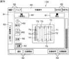
表示制御部111は、電源投入後またはアプリケーション起動後に、図6Aに示すトップ画面を操作表示部103に表示させる。トップ画面では、画面上端側の上部表示領域60とそれよりも画面下方側の下部表示領域61とに分割されている。上部表示領域60については、トップ画面よりも後に表示される各種画面(図6B~図6H)においても共通の固定表示画面となっている。下部表示領域61は、選択操作可能な操作用画像62をユーザが操作することで、異なる表示内容が表示される非固定表示領域である。
After powering on or starting an application, the
上部表示領域60の左側端部には、「地図へ」および「ヘルプ」の文字がそれぞれ描かれた2つの操作用画像62が表示されている。上部表示領域60の右側端部には、「GNSS」および「MENU」の文字がそれぞれ描かれた2つの操作用画像62が表示される。上部表示領域60中央部には、下部表示領域61に現在どのような画面が表示されているかが表示される。
On the left edge of the
図6Aに示すトップ画面の下部表示領域61には、「ほ場登録」、「作業機登録」、「パス生成」、「登録情報編集/削除」、「作業履歴」、「各種設定」および「アプリケーションを終了する」の文字がそれぞれ描かれた7つの操作用画像62が表示されている。
「ほ場登録」の文字が描かれた操作用画像62を選択操作することで、新たな圃場Fの情報を登録することができる。「ほ場登録」が描かれた操作用画像62の下方には、現在登録されている圃場Fの数が表示されている。「作業機登録」の文字が描かれた操作用画像62を選択操作することで、新たな田植機等の作業機の情報を登録することができる。「作業機登録」の文字が描かれた操作用画像62の下方には、現在登録されている作業機の数が表示されている。
The
By selecting the
圃場Fおよび作業機が少なくとも一つ以上登録されている場合に、「パス生成」の文字が描かれた操作用画像62がタッチ操作可能となる。「パス生成」の文字が描かれた操作用画像62が操作されると、表示制御部111は、図6Aに示すトップ画面を図6Bに示す圃場選択画面に遷移させる。
図6Bに示す圃場選択画面は、走行経路Rを生成した圃場Fを選択するための画面である。圃場選択画面では、下部表示領域61が、下部左側表示領域61Aと下部右側表示領域61Bとに分割されている。下部左側表示領域61Aには、登録された複数の圃場Fが含まれる地図情報画像63が表示される。
When at least one field F and one or more work machines are registered, the
The field selection screen shown in Fig. 6B is a screen for selecting a field F for which a travel route R has been generated. In the field selection screen, the
この実施形態では、圃場Fが7つ登録されており、地図情報画像63には、圃場F1~F7が表示される。田植機等の作業機が農作業を前回行った圃場F(この実施形態では圃場F2)には、所定のマーク(ピン画像)64が表示される。下部左側表示領域61Aの上端には、走行経路を生成したい圃場Fの選択をユーザに促す旨の選択促進画像64が表示される。
In this embodiment, seven fields F are registered, and fields F1 to F7 are displayed on the
下部右側表示領域61Bには、無線通信端末100に記憶されている圃場情報を示す圃場情報画像65の一覧が表示される。圃場情報画像65は、「距離順」、「名前順」および「登録順」等の文字が描かれた操作用画像62が選択操作されることで、操作された順番に並び替えて表示される。圃場選択画面においてユーザが特定の圃場F(この実施形態では圃場F3)を選択すると、選択された圃場Fは、他の圃場Fと識別可能に表示される。たとえば、選択された圃場Fは、枠の色が変えられて破線で囲まれる。選択された圃場Fの圃場情報を示す操作用画像62も、他の操作用画像62と識別可能に表示される。たとえば、選択された圃場Fの圃場情報を示す操作用画像62は、枠の色が変えられて太線にて囲まれる。
The lower
「戻る」の文字が描かれた操作用画像62が操作されると、表示制御部111は、図6Bに示す圃場選択画面を、一つ前の画面(ここでは、図6Aに示すトップ画面)に遷移させる。「次へ」の文字が描かれた操作用画像62が操作されると、表示制御部111は、図6Bに示す圃場選択画面を、次の画面(ここでは、図6Cに示す圃場領域選択画面)に遷移させる。「戻る」および「次へ」の操作用画像62の役割については、以下で説明するが画面においても同様である。
When the
図6Cに示す圃場領域選択画面は、圃場F内に作業領域Wを設定するための画面である。圃場領域選択画面においても、図6Bに示す圃場選択画面と同様に、下部表示領域61が、下部左側表示領域61Aと下部右側表示領域61Bとに分割されている。
下部右側表示領域61Bの表示内容は、図6Bに示す圃場選択画面と同じ構成である。下部左側表示領域61Aには、図6Bに示す圃場選択画面で選択された圃場F(この実施形態では圃場F3)を拡大した地図情報画像63が表示される。下部左側表示領域61Aの上端には、作業開位置位置(経路最始点SS)、終了位置(経路最終点EE)、作業方向の選択をユーザに促す旨の選択促進画像66が表示される。
The field area selection screen shown in Fig. 6C is a screen for setting a work area W within a field F. In the field area selection screen, similar to the field selection screen shown in Fig. 6B, the
The display contents of the lower
図6Dに示す作業車両選択画面は、走行経路Rで植付作業を行う田植機1(作業車両)を選択するための画面である。作業車両選択画面においても、図6Bに示す圃場選択画面と同様に、下部表示領域61が、下部左側表示領域61Aと下部右側表示領域61Bとに分割されている。
下部右側表示領域61Bには、無線通信端末100に記憶されている作業車両情報を示す作業車両情報画像67の一覧が表示される。作業車両情報画像67は、「名前順」および「登録順」等の操作用画像62が選択操作されることで、操作された順番に並び替えて表示される。作業車両選択画面においてユーザが特定の作業車両情報画像67を選択すると、他の作業車両情報画像67と識別可能に表示される。たとえば、選択された作業車両情報画像67は、枠の色が変えられて太線で囲まれる。特定の作業車両情報画像67が選択されると、下部左側表示領域61Aに、選択された作業車両の詳細情報が表示される。
The work vehicle selection screen shown in Fig. 6D is a screen for selecting a rice transplanter 1 (work vehicle) that will perform planting work on the travel route R. In the work vehicle selection screen, similar to the field selection screen shown in Fig. 6B, the
The lower
図6Eに示す作業態様設定画面は、田植機1の作業態様を設定するための画面である。作業態様としては、たとえば、縦取量、横送り量、株間、植付深さ等が挙げられる。作業態様設定画面の下部表示領域61には、作業態様が表示される。下部表示領域61には、マット数(苗マットの数量)、品種、葉齢、天候等の各種条件を考慮した作業態様の推奨設定が表示される。ユーザは、「変更」の文字が描かれた操作用画像62をタッチ操作して、各種条件および作業態様を変更することができる。
The work mode setting screen shown in FIG. 6E is a screen for setting the work mode of the
図6Fに示す植付方法設定画面は、植付方法を選択するための画面である。植付方法としては、たとえば、枕地領域Nに進入した田植機1をすぐに180°旋回させる田植機1を180°旋回させる通常旋回を用いる通常植付方法と、畦際まで植え付けをした後、後進してから田植機1を180°旋回させる畦際植付方法とが挙げられる。
植付方法設定画面の下部表示領域61には、植付方法選択用画像68が複数(この実施形態では2つ)表示される。下部表示領域61における左側部分には、畦際植付方法を選択するための畦際植付選択用画像68aが表示される。下部表示領域61において畦際植付選択用画像68aよりも下側の部分には、注意喚起画像69が表示される。注意喚起画像69は、田植機1を畦際で走行(旋回)させる際には、ユーザが継続ボタン83のタッチ操作を行う必要である旨(特定条件を満たす必要がある旨)のメッセージを含む画像である。下部表示領域61における右側部分には、通常植付方法を選択するための通常旋回選択用画像68bが表示される。
The planting method setting screen shown in Fig. 6F is a screen for selecting a planting method. Examples of the planting method include a normal planting method in which the
In the
植付方法設定画面においてユーザが特定の植付方法選択用画像68(この実施形態では、畦際植付選択用画像68a)を選択すると、選択された植付方法選択用画像68は、他の植付方法選択用画像68と識別可能に表示される。たとえば、選択された植付方法選択用画像68は、枠の色が変えられて太線で囲まれる。
図6Gに示す設定確認画面は、図6B~図6Gの画面で設定した内容を確認するための画面である。設定確認画面の下部表示領域61には、図6B~図6Gの画面で設定した内容が表示される。具体的には、「作業車両設定」、「ほ場領域」、「作業態様」および「植付方法設定」を示す欄が表示される。各欄に設けられた「編集」の文字が描かれた操作用画像62を操作することで、対応する設定を編集することができる。
When a user selects a particular planting method selection image 68 (in this embodiment, the ridge-edge
The setting confirmation screen shown in Fig. 6G is a screen for confirming the contents set on the screens of Fig. 6B to Fig. 6G. The contents set on the screens of Fig. 6B to Fig. 6G are displayed in a
下部表示領域61の下端に設けられた「パスを生成する」の文字が描かれた操作用画像62をタッチ操作することで、この設定内容に基づいて、制御部101の経路生成部110が走行経路Rを生成する。詳しくは、図6Fに示す植付方法設定画面において、ユーザが畦際植付選択用画像68aを選択した場合には、経路生成部110は、第1走行経路R1を生成する。図6Fに示す植付方法設定画面において、ユーザが通常旋回選択用画像68bを選択した場合には、経路生成部110は、第2走行経路R2を生成する。このように、操作表示部103は、ユーザが第1走行経路R1(第1連結経路C1)および第2走行経路R2(第2連結経路C2)のいずれを経路生成部110に生成させるかを選択できる選択画面(植付方法設定画面)を表示部の一例として機能している。走行経路Rが生成されると、表示制御部111は、図6Gの設定確認画面を、図6Hに示すパス生成結果に遷移する。
By touching the
図6Hに示すパス生成結果画面では、下部表示領域61が、下部左側表示領域61Aと下部右側表示領域61Bとに分割されている。下部左側表示領域61Aには、圃場Fを示す圃場画像70が表示される。圃場画像70には、経路生成部110によって生成された走行経路Rが描かれている。
下部右側表示領域61Bの中央部には、圃場画像70中の各部の説明が表示される。詳しくは、圃場画像70中には、作業領域Wを示す作業領域画像71、直線経路Pを示す自動作業パス画像72、連結経路Cを示す自動旋回パス画像73、田植機1の現在位置を示す作業車両位置画像74、経路最始点SSを示す開始位置画像75、および、経路最終点EEを示す終了位置画像76が表示されている。図6Hでは、第1走行経路R1が選択されたときの圃場画像70が示されている。また、自動旋回パス画像73が第1連結経路C1を示している。
6H, the
In the center of the lower
「このパスを転送する」の文字が描かれた操作用画像62をタッチ操作することによって、経路生成部110によって生成された走行経路Rに関する情報が、無線通信端末100から田植機1に送信される。
以下では、操作表示部103に表示される走行画面と、走行画面の操作方法について説明する。
By touching the
The following describes the driving screen displayed on the
図7A~図7Dは、操作表示部103に表示される走行画面を示す図である。走行画面は、経路生成部110によって生成された走行経路Rに関する情報が、無線通信端末100から田植機1に発信された後に、操作表示部103に表示される。図7A~図7Dに示す走行画面は、経路生成部110によって第1走行経路R1が生成された場合の例を示している。
Figures 7A to 7D are diagrams showing the driving screen displayed on the
図7A~図7Dに示す走行画面は、経路生成条件設定画面と同様に、上端側の上部表示領域60とそれよりも画面下方側の下部表示領域61とに分割されている。下部表示領域61の中央には、圃場画像70が表示される。
図7Aは、自動走行開始前の走行画面である。下部表示領域61における上端には、走行開始ボタン80と、走行停止ボタン81とが表示される。
7A to 7D are divided into an
7A shows the driving screen before the automatic driving starts. A driving start button 80 and a driving
走行開始ボタン80は、田植機1の自動走行を開始させるためにタッチ操作される画像である。ユーザが走行開始ボタン80をタッチ操作すると、無線通信部104から、走行開始信号が発信される。走行開始信号は、田植機1に自動走行の開始させるための信号である。田植機1が走行開始信号を受信すると、制御部4の自動走行制御部51が田植機1の自動走行を開始させる。
The driving start button 80 is an image that is touched to start the automatic driving of the
走行停止ボタン81は、エンジン10を停止させて田植機1の自動走行を停止させるためにタッチ操作される画像である。ユーザが走行停止ボタン81をタッチ操作すると、無線通信部104から停止信号が発信される。停止信号は、自動走行を停止させるための信号である。田植機1が停止信号を受信すると、制御部4の自動走行制御部51がエンジン10を停止させて田植機1の自動走行を停止させる。
The driving
ユーザが田植機1を移動させると、それに伴って走行画面の作業車両位置画像74が移動する。図7Aに示すように田植機1の自動走行を開始するための自動走行開始条件が満たされると、走行開始ボタン80がタッチ操作可能な状態となる。自動走行開始条件とは、たとえば、田植機1が経路最始点SSから所定距離範囲内に位置しており、田植機1の走行機体2の向きが進行方向に対して所定角度範囲内に収まっていることである。所定角度範囲とは、経路最始点SSから第1終点EP1に向かう方向を含む角度範囲である。すなわち、所定角度範囲には経路最始点SSから第1終点EP1に向かう方向だけでなく、走行機体2の向きが経路最始点SSから第1終点EP1に向かう方向から所定角度傾いた方向が含まれる。自動走行が開始されると、田植機1は、直線経路P(第1直線経路P1)に沿って走行する。
When the user moves the
図7Bは、自動走行開始後の走行画面である。自動走行が開始されると、自動走行の開始前に走行開始ボタン80(図7A参照)が表示されていた部分には、一時停止ボタン82が表示されている。
一時停止ボタン82は、エンジンを停止させることなく田植機1の自動走行を一時的に停止させるためにタッチ操作される画像である。ユーザが一時停止ボタン82をタッチ操作すると、無線通信部104から一時停止信号が発信される。田植機1が一時停止信号を受信すると、制御部4の自動走行制御部51がエンジン10を起動させたまま田植機1の自動走行を一時停止させる。
7B shows the driving screen after the automatic driving starts. When the automatic driving starts, a
The
直線経路Pにおいて田植機1が既に走行した部分に対応する箇所には、田植機1が既に走行したことを示す走行済画像77が表示されている。
図7Cは、田植機1が前進経路E1を前進して畦FPに接近したときの走行画面である。田植機1が畦FPに接近したときの走行画面には、継続ボタン83および警告画像84を表示されている。
At locations on the straight path P corresponding to the portions over which the
7C is a travel screen when the
「田植機1が畦FPに接近した」とは、たとえば、田植機1が畦FPと第1終点EP1との間に設けられた接近位置に到達したことである。「田植機1が畦FPに接近した」とは、田植機1が第1終点EP1を通過してから所定の表示開始時間が経過されたことであってもよい。この表示開始時間は、田植機1の車速にかかわらず一定であってもよいし、田植機1の車速に応じて可変であってもよい。
"The
継続ボタン83は、田植機1の自動走行および農作業を継続させるためにタッチ操作される画像である。継続ボタン83は、下部表示領域61において圃場画像70よりも下側の部分に表示される。
警告画像84は、下部表示領域61において圃場画像70よりも上側の部分に表示される。警告画像84は、田植機1が畦FPに接近した旨と、作業(自動走行)を継続するためには継続ボタン83をタッチ操作し続ける必要がある旨(特定条件の成立が必要である旨)とを表示する画像である。ユーザは、警告画像84の表示によって、特定条件が必要である旨を知ることができる。操作表示部103は、特定条件の成立が必要である旨をユーザに報知する報知部の一例である。
The continue
The
図7Dは、田植機1が後進経路E2を後進している状態を示す図である。田植機1が後進経路E2に沿って後進を開始すると、走行画面から継続ボタン83および警告画像84が消去される。
自動走行監視部112は、畦際を走行する田植機1の制御部4の自動走行制御部51や無線通信端末100の制御部101の操作表示部103に各種指令を付与することによって、田植機1の自動走行を監視する。自動走行監視部112は、走行画面の表示内容を表示制御部111の代わりに制御する場合がある。
7D is a diagram showing a state in which the
The automatic
以下では、自動走行監視部112の機能について詳細に説明する。
第1走行経路R1を田植機1が畦FPに接近すると、自動走行監視部112は、継続ボタン83および警告画像84を操作表示部103に同時に表示させる。田植機1の後進が開始されるまでの間タッチ操作が継続された場合には、自動走行監視部112は、操作表示部103から継続ボタン83および警告画像84を操作表示部103から消去する。
The functions of the automatic
When the
継続ボタン83および警告画像84が表示されてから所定時間が経過しても継続ボタン83のタッチ操作が開始されない場合には、自動走行監視部112は、一時停止信号を発信し、自動走行制御部51に田植機1を一時停止させる。
継続ボタン83のタッチ操作が開始された場合であっても、田植機1の後進が開始されるまでの間タッチ操作が継続されなかった場合には、自動走行監視部112は、一時停止信号を発信する。田植機1が一時停止した場合であっても、タッチ操作が開始され、再開必要時間が経過するまでの間そのタッチ操作が継続されれば、自動走行監視部112は、走行再開信号を発信する。走行再開信号は、田植機1に自動走行を再開させるための信号である。田植機1が走行再開信号を受信すると、自動走行制御部51が田植機1の自動走行を再開させる。
If the touch operation of the continue
Even when a touch operation of the continue
次に、自動走行監視部112が行う自動走行監視制御の詳細について説明する。図8は、自動走行監視部112による自動走行監視制御の一例を示すフローチャートである。
まず、自動走行監視部112は、田植機1の自動走行が開始されたか否かを判定する(ステップS1)。田植機1の自動走行が開始されたか否かは、たとえば、田植機1に向けて走行開始信号が発信されたか否かに基づいて判定される。田植機1の自動走行が開始されていない場合には(ステップS1:NO)、自動走行監視部112は、ステップS1に戻る。
Next, a detailed description will be given of the automatic driving monitoring control performed by the automatic
First, the automatic
田植機1の自動走行が開始された場合には(ステップS1:YES)、自動走行監視部112は、田植機1が畦FPに接近したか否かを判定する(ステップS2)。田植機1が畦FPに接近していない場合には(ステップS2:NO)、自動走行監視部112は、ステップS2に戻る。
田植機1が畦FPに接近した場合には(ステップS2:YES)、自動走行監視部112は、操作表示部103に、継続ボタン83および警告画像84を表示させる(ステップS3)。
When the automatic travel of the
When the
継続ボタン83および警告画像84が表示されると、自動走行監視部112は、継続ボタン83のタッチ操作が開始(ON)されたか否かを判定する(ステップS4)。継続ボタン83のタッチ操作が開始されない場合には(ステップS4:NO)、自動走行監視部112は、警告画像84の表示が開始されてから所定時間が経過したか否かを判定する(ステップS5)。警告画像84と継続ボタン83は同時に表示されるので、警告画像84が表示されるタイミングは、継続ボタン83が表示されるタイミングである。
When the continue
警告画像84の表示から所定時間が経過していない場合には(ステップS5:NO)、自動走行監視部112は、ステップS4に戻る。警告画像84の表示が開始されてから所定時間が経過するまでの間に継続ボタン83のタッチ操作が開始された場合には、(ステップS4:YES)、自動走行監視部112は、継続ボタン83のタッチ操作が継続されたか否かを判定する(ステップS6)。継続ボタン83のタッチ操作が継続されている場合には(ステップS6:NO)、自動走行監視部112は、田植機1が後進経路E2で後進を開始したか否かを判定する(ステップS7)。
If the predetermined time has not elapsed since the display of the warning image 84 (step S5: NO), the automatic
田植機1の後進が開始されない場合には(ステップS7:NO)、自動走行監視部112は、ステップS6に戻る。
継続ボタン83のタッチ操作が継続されている間に田植機1が後進経路E2で後進を開始した場合には(ステップS7:YES)、自動走行監視部112は、継続ボタン83および警告画像84を操作表示部103から消去する(ステップS8)。操作表示部103から継続ボタン83および警告画像84が消去されると、自動走行監視部112は、ステップS2に戻る。
If reverse movement of the
If the
ステップS5において、継続ボタン83がタッチ操作されることなく警告画像84の表示が開始されてから所定時間が経過した場合や(ステップS5:YES)、ステップS7において、田植機1が後進を開始する前に継続ボタン83のタッチ操作が解除(OFF)された場合には(ステップS7:YES)、自動走行監視部112は、田植機1に向けて一時停止信号を発信する(ステップS9)。
In step S5, if a predetermined time has elapsed since the
ステップS6において一時停止信号が発信されると、自動走行監視部112は、継続ボタン83のタッチ操作が開始されるか否かを判定する(ステップS10)。ステップS10において継続ボタン83のタッチ操作が開始されない場合には(ステップS10:NO)、自動走行監視部112は、ステップS10に戻る。
ステップS10において継続ボタン83のタッチ操作が開始されると(ステップS10:YES)、自動走行監視部112は、時間の計測を開始(タイムスタート)する(ステップS11)。タイムスタート後、自動走行監視部112は、継続ボタン83のタッチ操作が解除(OFF)されたか否かを判定する(ステップS12)。継続ボタン83のタッチ操作が解除されない場合には(ステップS12:NO)、自動走行監視部112は、タイムスタートから予め定められた再開必要時間が経過(タイムアップ)したか否かを判定する(ステップS13)。タイムアップしていない場合には(ステップS13:NO)、自動走行監視部112は、ステップS12に戻る。
When the temporary stop signal is transmitted in step S6, the automatic
When the touch operation of the continue
ステップS13において、タイムアップしたと判定された場合には(ステップS13:YES)、すなわち、継続ボタン83のタッチ操作が再開必要時間が経過するまでの間継続された場合には、自動走行監視部112は、田植機1に向けて走行再開信号を発信する(ステップS14)。走行再開信号が発信されると、自動走行監視部112は、ステップS6に戻る。
If it is determined in step S13 that the time is up (step S13: YES), that is, if the touch operation of the continue
ステップS13においてタイムアップする前に継続ボタン83のタッチ操作が解除された場合には(ステップS12:YES)、再開必要時間の計測が中止され計測時間が零に(タイムリセット)される(ステップS15)。タイムリセットされると、自動走行監視部112は、ステップS10に戻る。
なお、第2走行経路R2における田植機1の自動走行は、継続ボタン83のタッチ操作を要件としない。そのため、経路生成部110が第2走行経路R2を生成した場合には、田植機1の位置にかかわらず、操作表示部103には継続ボタン83が表示されない。また、田植機1が第2走行経路R2を自動走行する際には、自動走行監視部112による自動走行監視制御が実行されない。
If the touch operation of the continue
The automatic travel of the
この実施形態の自動走行システムでは、経路生成部110は、田植機1が畦際を走行する際に継続ボタン83のタッチ操作が行われなければ(特定条件が成立していなければ)田植機1の自動走行が停止される第1走行経路R1と、継続ボタン83のタッチ操作を自動走行の要件としない第2走行経路R2とを選択的に生成することができる。つまり、ユーザの希望に応じて、枕地領域Nにおける田植機1の走行形態が異なる走行経路Rを選択的に生成することができる。
In the automatic driving system of this embodiment, the
この実施形態の自動走行システムでは、第1走行経路R1および第2走行経路R2のいずれを経路生成部110に生成させるかを選択できる植付方法設定画面(選択画面)が操作表示部103に表示される。そして、操作表示部103には、畦際(前進経路E1における畦FP側の端部付近)で田植機1を自動走行させるためには継続ボタン83のタッチ操作が必要な旨の注意喚起画像69が表示される。
In the automatic driving system of this embodiment, a planting method setting screen (selection screen) that allows the user to select whether the first driving route R1 or the second driving route R2 is to be generated by the
この構成によれば、ユーザは、走行経路Rの生成時に、特定条件の成立の要否を知ることができる。そのため、ユーザは、第1走行経路R1を選択した場合には、自動走行中の特定条件の成立に適切に注意を払うことができ、第2走行経路R2を選択した場合には、自動走行中の特定条件の成立に注意を払う手間を省くことができる。したがって、田植機1を自動走行させる際のユーザの負担を低減することができる。
According to this configuration, the user can know whether or not certain conditions need to be met when the driving route R is generated. Therefore, when the user selects the first driving route R1, the user can pay appropriate attention to whether certain conditions are met during automatic driving, and when the user selects the second driving route R2, the user can avoid the trouble of paying attention to whether certain conditions are met during automatic driving. Therefore, the burden on the user when automatically driving the
この実施形態の自動走行システムでは、第1走行経路R1の前進経路E1を自動走行中の田植機1が畦FPに接近したときに特定条件を満たさない場合には、自動走行監視部112が、自動走行制御部51に田植機1の自動走行を停止させる。前進経路E1における畦FP側の端部に近づいたときにユーザが継続ボタン83をタッチ操作し続けていなければ、田植機1の自動走行が停止される。そのため、自動走行中の田植機1が畦FPに近づいたことにユーザが気付かない場合に、田植機1の自動走行を強制的に停止させることができる。したがって、ユーザによる監視の下で田植機1に畦際を走行させることができるので、畦FPへの田植機1の衝突を抑制することができる。
In the automatic driving system of this embodiment, if the
一方、田植機1が第2走行経路R2を自動走行する際には、田植機1が畦際まで近づかないので、田植機1の一時停止に煩わされることなく、田植機1をスムーズに自動走行させることができる。
また、この実施形態の自動走行システムでは、田植機1が畦FPに接近した際に、継続ボタン83のタッチ操作が必要である旨を自動走行監視部112がユーザに報知する。そして、報知後に所定時間が経過しても継続ボタン83のタッチ操作が行われない場合には、自動走行監視部112は、自動走行制御部51に田植機1の自動走行を停止させる。
On the other hand, when the
In the automatic driving system of this embodiment, when the
この構成によれば、ユーザは、田植機1の自動走行中に継続ボタン83のタッチ操作が必要なタイミングを、操作表示部103による警告画像84の表示によって知ることができる。したがって、自動走行が強制的に停止される頻度を低減することができるので、田植機1を走行経路Rに沿ってスムーズに自動走行させることができる。しかも、所定時間が経過しても継続ボタン83のタッチ操作が開始されない場合には田植機1の自動走行が停止されるので、ユーザが操作表示部103に表示された警告画像84を認識し損なった場合であっても、第1連結経路C1における田植機1の自動走行を強制的に停止させることができる。そのため、田植機1を自動走行させる際のユーザの負担を低減することができる。
According to this configuration, the user can know the timing when the touch operation of the continue
この発明は、以上に説明した実施形態に限定されるものではなく、さらに他の形態で実施することができる。
上述の実施形態では、自動走行監視部112は、田植機1が後進経路E2で後進を開始した場合に継続ボタン83および警告画像84を消去するとした。しかし、上述した実施形態とは異なり、田植機1が旋回経路E3で旋回を開始した場合に自動走行監視部112が継続ボタン83および警告画像84を消去するとしてもよい。また、田植機1が旋回経路E3で旋回し終えた場合に自動走行監視部112が継続ボタン83および警告画像84を消去するとしてもよい。
The present invention is not limited to the above-described embodiment, and can be embodied in other forms.
In the above embodiment, the automatic
また、上述の実施形態では、操作表示部103に表示される継続ボタン83がタッチ操作されることを特定条件とした。しかしながら、特定条件は、継続ボタン83のタッチ操作に限られない。たとえば、無線通信端末100に設けられた把持センサがユーザによる無線通信端末100の把持を検出していることを特定条件としてもよい。あるいは、無線通信端末100とは別に設けられたリモコン(図示せず)の操作を特定条件としてもよい。リモコンは、たとえば、走行停止信号を発信することができる緊急停止用リモコンである。
In the above embodiment, the specific condition is that the continue
また、走行経路Rを走行し終えた後に、枕地領域Nを走行する周回工程においても、田植機1が自動走行してもよい。この場合、周回工程が開始されてから終了するまでの間、自動走行監視部112が継続ボタン83および警告画像84を操作表示部103に表示する。
また、上述の実施形態では、操作表示部103が報知部の一例であるとした。しかし、上述の実施形態とは異なり、報知部として、特定条件の成立が必要である旨の警告音を発するスピーカが無線通信端末100に設けられていてもよい。
In addition, after completing travel along the travel route R, the
In the above embodiment, the
(発明の付記)
この発明の一実施形態は、内部領域と前記内部領域を取り囲む枕地領域とを有する圃場において、前記内部領域に設定され第1始点および第1終点を接続してなる第1直線経路と、前記内部領域に設定され第2始点および第2終点を接続してなる第2直線経路と、前記枕地領域に設定され前記第1終点および前記第2始点を連結する連結経路とを有する走行経路に沿って農作業機を自動走行させる自動走行システムであって、前記連結経路として、特定条件が成立していなければ前記農作業機の自動走行が停止されるように設定された第1連結経路と、前記特定条件を前記農作業機の自動走行の要件としない第2連結経路とを選択的に生成することができる経路生成部を含む、自動走行システムを提供する。
(Appendix to the invention)
One embodiment of the present invention provides an automatic driving system that automatically drives an agricultural working machine along a driving path in a field having an internal area and a headland area surrounding the internal area, the driving path having a first straight path set in the internal area connecting a first starting point and a first ending point, a second straight path set in the internal area connecting a second starting point and a second ending point, and a connecting path set in the headland area connecting the first ending point and the second starting point, the automatic driving system including a path generation unit that can selectively generate, as the connecting path, a first connecting path that is set so that the automatic driving of the agricultural working machine is stopped if a specific condition is not met, and a second connecting path that does not require the specific condition as a requirement for the automatic driving of the agricultural working machine.
この構成によれば、経路生成部は、枕地領域に設定された連結経路として、農作業機に自動走行させるためには特定条件の成立が必要な第1連結経路と、特定条件を農作業機の自動走行の要件としない第2連結経路とを選択的に生成することができる。つまり、ユーザの希望に応じて、枕地領域における農作業機の走行形態が異なる走行経路を選択的に生成することができる。 According to this configuration, the route generation unit can selectively generate, as a connecting route set in the headland area, a first connecting route that requires the establishment of a specific condition for the agricultural work machine to travel automatically, and a second connecting route that does not require a specific condition for the agricultural work machine to travel automatically. In other words, it is possible to selectively generate travel routes with different travel modes of the agricultural work machine in the headland area according to the user's wishes.
ここで、たとえば、第1連結経路が、第1終点から圃場の畦に向かって農作業機を前進させる前進経路と、前進経路における畦側の端部から第1終点に向かって農作業機を後進させる後進経路と、後進経路における第1終点側の端部から第2始点に向かって前記農作業機を旋回させる旋回経路とによって構成されており、第2連結経路が、第1終点から第2始点に向かって農作業機をさせる旋回経路のみによって構成されている場合を想定する。 Here, for example, it is assumed that the first connecting path is composed of a forward path that moves the agricultural work machine forward from the first end point toward the ridge of the field, a reverse path that moves the agricultural work machine backward from the end of the forward path on the ridge side toward the first end point, and a turning path that turns the agricultural work machine from the end of the reverse path on the first end point side toward the second starting point, and the second connecting path is composed only of a turning path that moves the agricultural work machine from the first end point toward the second starting point.
この場合、たとえば、農作業機が前進経路における畦側の端部に近づいたときにユーザが通信端末等をタッチ操作し続けることを特定条件とすることで、第1連結経路を自動走行中の農作業機が畦に近づいたことにユーザが気付かなったとしても、農作業機の自動走行を強制的に停止させることができる。したがって、ユーザの監視の下で農作業機に畦際を走行させることができるので、畦への農作業機の衝突を抑制することができる。 In this case, for example, by setting a specific condition that the user continues to touch the communication terminal or the like when the agricultural work machine approaches the end of the ridge on the forward path, the automatic travel of the agricultural work machine can be forcibly stopped even if the user does not notice that the agricultural work machine, which is automatically traveling on the first connecting path, has approached the ridge. Therefore, the agricultural work machine can be caused to travel along the edge of the ridge under the supervision of the user, thereby preventing the agricultural work machine from colliding with the ridge.
この発明の一実施形態では、前記自動走行システムが、ユーザが前記第1連結経路および前記第2連結経路のいずれを前記経路生成部に生成させるかを選択できる選択画面を表示する表示部と、前記選択画面を表示部に表示させる表示制御部とをさらに含む。そして、前記経路生成部が前記第1連結経路を生成する場合には、前記表示制御部が、前記第1連結経路において前記農作業機を自動走行させるためには前記特定条件の成立が必要な旨を前記表示部に表示させる。 In one embodiment of the present invention, the automatic driving system further includes a display unit that displays a selection screen on which the user can select whether to have the route generation unit generate the first connecting route or the second connecting route, and a display control unit that causes the selection screen to be displayed on the display unit. When the route generation unit generates the first connecting route, the display control unit causes the display unit to display a message indicating that the specific condition must be met in order for the agricultural work machine to automatically travel on the first connecting route.
この構成によれば、ユーザは、走行経路の生成時に、特定条件の成立の要否を知ることができる。そのため、ユーザは、第1連結経路を選択した場合には、自動走行中の特定条件の成立に適切に注意を払うことができ、第2連結経路を選択した場合には、自動走行中の特定条件の成立に注意を払う手間を省くことができる。したがって、農作業機を自動走行させる際のユーザの負担を低減することができる。 According to this configuration, the user can know whether or not certain conditions need to be met when generating a driving route. Therefore, when the user selects the first connecting route, the user can pay appropriate attention to whether certain conditions are met during automatic driving, and when the user selects the second connecting route, the user can avoid the trouble of paying attention to whether certain conditions are met during automatic driving. Therefore, the burden on the user when automatically driving an agricultural machine can be reduced.
この発明の一実施形態では、前記自律走行システムが、前記走行経路に沿って前記農作業機を自動走行させる自動走行制御部と、前記農作業機の自動走行中に、前記特定条件の成立が必要である旨をユーザに報知する報知部とをさらに含む。そして、前記自動走行制御部が、前記報知部が報知した後、所定時間以内に前記特定条件が成立しなければ前記農作業機の自動走行を停止させる。 In one embodiment of the present invention, the autonomous driving system further includes an automatic driving control unit that automatically drives the agricultural work machine along the driving route, and a notification unit that notifies a user that the specific condition needs to be met while the agricultural work machine is automatically driving. Then, the automatic driving control unit stops the automatic driving of the agricultural work machine if the specific condition is not met within a predetermined time after the notification unit issues the notification.
この構成によれば、ユーザは、農作業機の自動走行中に特定条件の成立が必要なタイミングを、報知部の報知によって知ることができる。したがって、自動走行が強制的に停止される頻度を低減することができるので、農作業機を走行経路に沿ってスムーズに自動走行させることができる。しかも、所定時間以内に特定条件が成立しなければ農作業機の自動走行が停止されるので、ユーザが報知制御部による報知を認識し損なった場合であっても、第1連結経路における農作業機の自動走行を強制的に停止させることができる。そのため、農作業機を自動走行させる際のユーザの負担を低減することができる。 According to this configuration, the user can know the timing when a specific condition needs to be met during the automatic travel of the agricultural machine through a notification from the notification unit. This reduces the frequency with which automatic travel is forcibly stopped, allowing the agricultural machine to travel smoothly automatically along the travel route. Moreover, since the automatic travel of the agricultural machine is stopped if the specific condition is not met within a predetermined time, even if the user fails to recognize the notification from the notification control unit, the automatic travel of the agricultural machine on the first connection route can be forcibly stopped. This reduces the burden on the user when automatically traveling the agricultural machine.
この発明の別の実施形態は、内部領域と前記内部領域を取り囲む枕地領域とを有する圃場において、前記内部領域に設定され第1始点および第1終点を接続してなる第1直線経路と、前記内部領域に設定され第2始点および第2終点を接続してなる第2直線経路と、前記枕地領域に設定され前記第1終点および前記第2始点を連結する連結経路とを有する走行経路に沿って農作業機を自動走行させる自動走行システムであって、前記連結経路が、前記第1終点から前記圃場の畦に向かって前記農作業機を前進させる前進経路と、前記前進経路における前記畦側の端部から前記第1終点に向かって前記農作業機を後進させる後進経路と、前記後進経路における第1終点側の端部および前記第2始点を連結し、前記農作業機を旋回させる旋回経路とを有し、前記走行経路に沿って前記農作業機を自動走行させる自動走行制御部と、前記農作業機が前記畦に接近したときに特定条件が成立していない場合には、前記自動走行制御部に前記農作業機の自動走行を停止させる自動走行監視部とを含む自動走行システムを提供する。 Another embodiment of the present invention is an automatic driving system that automatically drives an agricultural machine along a driving path that includes a first straight path that is set in the inner area and connects a first starting point and a first ending point, a second straight path that is set in the inner area and connects a second starting point and a second ending point, and a connecting path that is set in the headland area and connects the first ending point and the second starting point, in a farm field having an inner area and a headland area surrounding the inner area, and the connecting path moves the agricultural machine forward from the first ending point toward a ridge of the farm field. The system includes a forward path that moves the agricultural work machine backward from the end of the forward path on the ridge side toward the first end point, a reverse path that moves the agricultural work machine backward from the end of the forward path on the ridge side toward the first end point, and a turning path that connects the end of the reverse path on the first end point side and the second start point and turns the agricultural work machine, an automatic driving control unit that automatically drives the agricultural work machine along the traveling path, and an automatic driving monitoring unit that causes the automatic driving control unit to stop the automatic driving of the agricultural work machine if a specific condition is not met when the agricultural work machine approaches the ridge.
この構成によれば、農作業機が畦に接近したときに特定条件が成立していない場合には、自動走行監視部が自動走行制御部に農作業機の自動走行を停止させる。たとえば、特定条件が、ユーザが通信端末をタッチ操作し続けていることである場合には、農作業機に畦が近づいたことにユーザが気付かなかったとしても、農作業機の自動走行を強制的に停止させることができる。したがって、ユーザの監視の下で農作業機に畦際を走行させることができるので、畦への農作業機の衝突を抑制することができる。 According to this configuration, if the specific condition is not met when the agricultural work machine approaches a ridge, the automatic driving monitoring unit causes the automatic driving control unit to stop the automatic driving of the agricultural work machine. For example, if the specific condition is that the user continues to touch the communication terminal, the automatic driving of the agricultural work machine can be forcibly stopped even if the user does not notice that the agricultural work machine is approaching the ridge. Therefore, since the agricultural work machine can be driven along the edge of the ridge under the supervision of the user, collision of the agricultural work machine with the ridge can be suppressed.
この発明の別の実施形態では、前記自動走行監視部が、前記農作業機が前記畦に接近した際に前記特定条件の成立が必要である旨をユーザに報知し、当該報知後に所定時間が経過しても前記特定条件を満たさない場合には、前記自動走行制御部に前記農作業機の自動走行を停止させる。
この構成によれば、ユーザは、農作業機の自動走行中に特定条件の成立が必要なタイミングを、自動走行監視部からの報知によって知ることができる。したがって、自動走行が強制的に停止される頻度を低減することができるので、農作業機を走行経路に沿ってスムーズに自動走行させることができる。しかも、所定時間以内に特定条件が成立しなければ農作業機の自動走行が停止されるので、ユーザが自動走行監視部からの報知を認識し損なった場合であっても、第1連結経路における農作業機の自動走行を強制的に停止させることができる。そのため、農作業機を自動走行させる際のユーザの負担を低減することができる。
In another embodiment of the present invention, the automatic driving monitoring unit notifies the user that the specific condition must be met when the agricultural work machine approaches the ridge, and if the specific condition is not met even after a predetermined time has elapsed after the notification, causes the automatic driving control unit to stop the automatic driving of the agricultural work machine.
According to this configuration, the user can know the timing when the specific condition needs to be satisfied during the automatic travel of the agricultural machine by the notification from the automatic travel monitoring unit. Therefore, the frequency of the automatic travel being forcibly stopped can be reduced, so that the agricultural machine can be automatically traveled smoothly along the travel route. Moreover, since the automatic travel of the agricultural machine is stopped if the specific condition is not satisfied within a predetermined time, even if the user fails to recognize the notification from the automatic travel monitoring unit, the automatic travel of the agricultural machine on the first connection route can be forcibly stopped. Therefore, the burden on the user when the agricultural machine is automatically traveled can be reduced.
この発明の一態様に係る自動走行システムは、内部領域と前記内部領域を取り囲む枕地領域とを有する圃場において、前記内部領域に設定される第1経路と、前記内部領域に設定される第2経路と、前記枕地領域に設定され前記第1経路の終点および前記第2経路の始点を連結する連結経路とを有し、農作業機を自動走行させる走行経路を生成する自動走行システムであって、経路生成部を含む。前記経路生成部は、前記走行経路として、前記農作業機の自動走行を停止可能に設定された前進経路を含む第1走行経路と、前記第1走行経路と同一の状況下で前記農作業機の自動走行を停止させない第2走行経路と、を選択的に生成することができる。 An automatic driving system according to one aspect of the present invention is an automatic driving system that generates a driving route for automatically driving an agricultural machine in a field having an internal area and a headland area surrounding the internal area, the driving route having a first route set in the internal area, a second route set in the internal area, and a connecting route set in the headland area connecting an end point of the first route and a start point of the second route, and includes a route generating unit. The route generating unit can selectively generate, as the driving route, a first driving route including a forward route set so that the automatic driving of the agricultural machine can be stopped, and a second driving route that does not stop the automatic driving of the agricultural machine under the same circumstances as the first driving route.
1 :田植機(自動走行システム)
51 :自動走行制御部
100 :無線通信端末(自動走行システム)
103 :操作表示部(表示部、報知部)
110 :経路生成部
111 :表示制御部
112 :自動走行監視部
C :連結経路
C1 :第1連結経路
C2 :第2連結経路
E1 :前進経路
E2 :後進経路
E3 :旋回経路
EP1 :第1終点
EP2 :第2終点
F :圃場
FP :畦
N :枕地領域
P1 :第1直線経路
P2 :第2直線経路
R :走行経路
R1 :第1走行経路
R2 :第2走行経路
SP1 :第1始点
SP2 :第2始点
W :作業領域(内部領域)
1: Rice transplanter (automatic driving system)
51: Automatic driving control unit 100: Wireless communication terminal (automatic driving system)
103: Operation display unit (display unit, notification unit)
110: Route generating unit 111: Display control unit 112: Automatic travel monitoring unit C: Connecting route C1: First connecting route C2: Second connecting route E1: Forward route E2: Reverse route E3: Turning route EP1: First end point EP2: Second end point F: Field FP: Ridge N: Headland area P1: First straight route P2: Second straight route R: Travel route R1: First travel route R2: Second travel route SP1: First starting point SP2: Second starting point W: Working area (internal area)
Claims (5)
前記農作業機を畦の手前まで前進させた後に、前記農作業機を一時停止させ、前記農作業機が一時停止した状態でユーザによる所定の操作が行われると、前記農作業機を前記畦に向けて前進させる走行再開処理を実行する、
自動走行システム。 An automatic driving system that automatically drives an agricultural machine based on a driving route in a farm field,
after the agricultural work machine is advanced to just before the ridge, the agricultural work machine is temporarily stopped, and when a predetermined operation is performed by a user in a state where the agricultural work machine is temporarily stopped, a travel resumption process is executed to advance the agricultural work machine toward the ridge.
Autonomous driving system.
請求項1に記載の自動走行システム。 In the travel resumption process, the agricultural work machine is moved forward only while the predetermined operation is continued.
The automated driving system according to claim 1 .
請求項1または2に記載の自動走行システム。 The predetermined operation includes an operation of a remote control.
The automated driving system according to claim 1 or 2.
前記走行再開処理において、前記農作業機は前記枕地領域を走行する、
請求項1~3のいずれか1項に記載の自動走行システム。 The field has a headland region surrounded by the ridge and an inner region surrounded by the headland region,
In the traveling resumption process, the agricultural work machine travels in the headland area.
The automatic driving system according to any one of claims 1 to 3.
前記農作業機を畦の手前まで前進させた後に、前記農作業機を一時停止させ、前記農作業機が一時停止した状態でユーザによる所定の操作が行われると、前記農作業機を前記畦に向けて前進させること、を有する、
農作業機制御方法。 An agricultural machine control method for automatically driving an agricultural machine based on a driving route in a farm field, comprising:
and temporarily stopping the agricultural work machine after moving the agricultural work machine forward to a position just before a ridge, and moving the agricultural work machine forward toward the ridge when a predetermined operation is performed by a user in a state where the agricultural work machine is temporarily stopped.
A method for controlling agricultural machinery.
Priority Applications (1)
| Application Number | Priority Date | Filing Date | Title |
|---|---|---|---|
| JP2023025698A JP7556074B2 (en) | 2018-03-22 | 2023-02-22 | Automatic driving system and agricultural machine control method |
Applications Claiming Priority (3)
| Application Number | Priority Date | Filing Date | Title |
|---|---|---|---|
| JP2018054761A JP6917935B2 (en) | 2018-03-22 | 2018-03-22 | Autonomous driving system |
| JP2021119414A JP7234305B2 (en) | 2018-03-22 | 2021-07-20 | automatic driving system |
| JP2023025698A JP7556074B2 (en) | 2018-03-22 | 2023-02-22 | Automatic driving system and agricultural machine control method |
Related Parent Applications (1)
| Application Number | Title | Priority Date | Filing Date |
|---|---|---|---|
| JP2021119414A Division JP7234305B2 (en) | 2018-03-22 | 2021-07-20 | automatic driving system |
Publications (2)
| Publication Number | Publication Date |
|---|---|
| JP2023054214A JP2023054214A (en) | 2023-04-13 |
| JP7556074B2 true JP7556074B2 (en) | 2024-09-25 |
Family
ID=68108369
Family Applications (3)
| Application Number | Title | Priority Date | Filing Date |
|---|---|---|---|
| JP2018054761A Expired - Fee Related JP6917935B2 (en) | 2018-03-22 | 2018-03-22 | Autonomous driving system |
| JP2021119414A Active JP7234305B2 (en) | 2018-03-22 | 2021-07-20 | automatic driving system |
| JP2023025698A Active JP7556074B2 (en) | 2018-03-22 | 2023-02-22 | Automatic driving system and agricultural machine control method |
Family Applications Before (2)
| Application Number | Title | Priority Date | Filing Date |
|---|---|---|---|
| JP2018054761A Expired - Fee Related JP6917935B2 (en) | 2018-03-22 | 2018-03-22 | Autonomous driving system |
| JP2021119414A Active JP7234305B2 (en) | 2018-03-22 | 2021-07-20 | automatic driving system |
Country Status (1)
| Country | Link |
|---|---|
| JP (3) | JP6917935B2 (en) |
Families Citing this family (14)
| Publication number | Priority date | Publication date | Assignee | Title |
|---|---|---|---|---|
| JP7343405B2 (en) * | 2020-01-14 | 2023-09-12 | 株式会社クボタ | agricultural vehicle |
| JP7515261B2 (en) * | 2020-01-14 | 2024-07-12 | 株式会社クボタ | Route Management System |
| JP7732839B2 (en) * | 2021-10-14 | 2025-09-02 | 株式会社三共 | gaming machines |
| JP7732840B2 (en) * | 2021-10-14 | 2025-09-02 | 株式会社三共 | gaming machines |
| JP7732843B2 (en) * | 2021-10-14 | 2025-09-02 | 株式会社三共 | gaming machines |
| JP7732842B2 (en) * | 2021-10-14 | 2025-09-02 | 株式会社三共 | gaming machines |
| JP7732841B2 (en) * | 2021-10-14 | 2025-09-02 | 株式会社三共 | gaming machines |
| JP7771633B2 (en) * | 2021-11-05 | 2025-11-18 | オムロン株式会社 | Map creation systems and programs |
| JP7609760B2 (en) * | 2021-11-26 | 2025-01-07 | ヤンマーホールディングス株式会社 | Autonomous driving method, work vehicle, and automated driving system |
| JP2023081438A (en) | 2021-12-01 | 2023-06-13 | ヤンマーホールディングス株式会社 | Automatic driving method, working vehicle and automatic driving system |
| JP7604359B2 (en) * | 2021-12-28 | 2024-12-23 | 株式会社クボタ | Agricultural work support systems, agricultural machinery, agricultural work support devices |
| JP7638932B2 (en) * | 2022-06-13 | 2025-03-04 | 株式会社クボタ | Work vehicle |
| JP7813204B2 (en) | 2022-08-18 | 2026-02-12 | ヤンマーホールディングス株式会社 | Route setting method, route setting system, and route setting program |
| JP2025057536A (en) * | 2023-09-28 | 2025-04-09 | 井関農機株式会社 | Rice field art creation system |
Citations (6)
| Publication number | Priority date | Publication date | Assignee | Title |
|---|---|---|---|---|
| JP2004201530A (en) | 2002-12-24 | 2004-07-22 | Iseki & Co Ltd | Work vehicle |
| JP2015112071A (en) | 2013-12-12 | 2015-06-22 | 株式会社クボタ | Field work machine |
| JP2015159735A (en) | 2014-02-26 | 2015-09-07 | 井関農機株式会社 | Seedling transplanter |
| JP2016170523A (en) | 2015-03-11 | 2016-09-23 | 株式会社クボタ | Travel control device |
| US20170118915A1 (en) | 2015-11-03 | 2017-05-04 | Claas Selbstfahrende Erntemaschinen Gmbh | Surroundings detection device for agricultural work machines |
| JP2018033344A (en) | 2016-08-30 | 2018-03-08 | 井関農機株式会社 | Agricultural work machine |
Family Cites Families (6)
| Publication number | Priority date | Publication date | Assignee | Title |
|---|---|---|---|---|
| JPS6416504A (en) * | 1987-07-13 | 1989-01-20 | Kubota Ltd | Steering controller for rice transplanter |
| JP2847674B2 (en) * | 1991-11-14 | 1999-01-20 | 日本輸送機株式会社 | Unmanned vehicle control method |
| JP2880479B2 (en) * | 1997-03-10 | 1999-04-12 | 株式会社クボタ | Combine transmission structure |
| JP3469814B2 (en) * | 1999-04-16 | 2003-11-25 | 三洋電機株式会社 | Golf cart |
| US20140297090A1 (en) * | 2011-11-11 | 2014-10-02 | Hitachi, Ltd. | Autonomous Mobile Method and Autonomous Mobile Device |
| KR102125112B1 (en) * | 2014-05-22 | 2020-06-22 | 얀마 파워 테크놀로지 가부시키가이샤 | Running system of work vehicle |
-
2018
- 2018-03-22 JP JP2018054761A patent/JP6917935B2/en not_active Expired - Fee Related
-
2021
- 2021-07-20 JP JP2021119414A patent/JP7234305B2/en active Active
-
2023
- 2023-02-22 JP JP2023025698A patent/JP7556074B2/en active Active
Patent Citations (6)
| Publication number | Priority date | Publication date | Assignee | Title |
|---|---|---|---|---|
| JP2004201530A (en) | 2002-12-24 | 2004-07-22 | Iseki & Co Ltd | Work vehicle |
| JP2015112071A (en) | 2013-12-12 | 2015-06-22 | 株式会社クボタ | Field work machine |
| JP2015159735A (en) | 2014-02-26 | 2015-09-07 | 井関農機株式会社 | Seedling transplanter |
| JP2016170523A (en) | 2015-03-11 | 2016-09-23 | 株式会社クボタ | Travel control device |
| US20170118915A1 (en) | 2015-11-03 | 2017-05-04 | Claas Selbstfahrende Erntemaschinen Gmbh | Surroundings detection device for agricultural work machines |
| JP2018033344A (en) | 2016-08-30 | 2018-03-08 | 井関農機株式会社 | Agricultural work machine |
Also Published As
| Publication number | Publication date |
|---|---|
| JP7234305B2 (en) | 2023-03-07 |
| JP2019168812A (en) | 2019-10-03 |
| JP6917935B2 (en) | 2021-08-11 |
| JP2021168684A (en) | 2021-10-28 |
| JP2023054214A (en) | 2023-04-13 |
Similar Documents
| Publication | Publication Date | Title |
|---|---|---|
| JP7556074B2 (en) | Automatic driving system and agricultural machine control method | |
| JP6804999B2 (en) | Work driving management system | |
| JP2018092401A (en) | Route generation system | |
| KR102647044B1 (en) | Working vehicle | |
| CN113574486A (en) | Automatic driving system | |
| JP2017127290A (en) | Agricultural working vehicle | |
| KR20200067232A (en) | Working vehicle | |
| CN114616945A (en) | Working machine | |
| JP7515382B2 (en) | Work Machine | |
| CN113038822A (en) | Working vehicle | |
| JP2019076059A (en) | Field working machine | |
| JP2018097621A (en) | Automatic steering control device | |
| JP2024180443A (en) | Work vehicles | |
| JP6477812B2 (en) | Work vehicle | |
| JP7044477B2 (en) | Automatic steering control device | |
| JP7076524B2 (en) | Work drive management system and work drive management device | |
| JP2018093793A5 (en) | ||
| JP6477811B2 (en) | Work vehicle | |
| JP7657996B2 (en) | Autonomous driving system and method | |
| KR20230110486A (en) | Work machine and work driving system | |
| CN114559954A (en) | Working machine | |
| JP7762630B2 (en) | Autonomous driving method, work vehicle, and automated driving system | |
| AU2022428247B2 (en) | Agricultural Work Assistance System, Agricultural Machine | |
| JP7641834B2 (en) | Paddy field farming machine | |
| JP7717657B2 (en) | Autonomous driving method, automatic driving system, and automatic driving program |
Legal Events
| Date | Code | Title | Description |
|---|---|---|---|
| A621 | Written request for application examination |
Free format text: JAPANESE INTERMEDIATE CODE: A621 Effective date: 20230222 |
|
| A977 | Report on retrieval |
Free format text: JAPANESE INTERMEDIATE CODE: A971007 Effective date: 20240229 |
|
| A131 | Notification of reasons for refusal |
Free format text: JAPANESE INTERMEDIATE CODE: A131 Effective date: 20240402 |
|
| TRDD | Decision of grant or rejection written | ||
| A01 | Written decision to grant a patent or to grant a registration (utility model) |
Free format text: JAPANESE INTERMEDIATE CODE: A01 Effective date: 20240903 |
|
| A61 | First payment of annual fees (during grant procedure) |
Free format text: JAPANESE INTERMEDIATE CODE: A61 Effective date: 20240911 |
|
| R150 | Certificate of patent or registration of utility model |
Ref document number: 7556074 Country of ref document: JP Free format text: JAPANESE INTERMEDIATE CODE: R150 |