JP7535397B2 - Reducer, fluid motor with reducer, construction machine, and method for manufacturing reducer - Google Patents
Reducer, fluid motor with reducer, construction machine, and method for manufacturing reducer Download PDFInfo
- Publication number
- JP7535397B2 JP7535397B2 JP2020116066A JP2020116066A JP7535397B2 JP 7535397 B2 JP7535397 B2 JP 7535397B2 JP 2020116066 A JP2020116066 A JP 2020116066A JP 2020116066 A JP2020116066 A JP 2020116066A JP 7535397 B2 JP7535397 B2 JP 7535397B2
- Authority
- JP
- Japan
- Prior art keywords
- sun gear
- hardening treatment
- face
- reducer
- cover
- Prior art date
- Legal status (The legal status is an assumption and is not a legal conclusion. Google has not performed a legal analysis and makes no representation as to the accuracy of the status listed.)
- Active
Links
Images


Classifications
-
- F—MECHANICAL ENGINEERING; LIGHTING; HEATING; WEAPONS; BLASTING
- F16—ENGINEERING ELEMENTS AND UNITS; GENERAL MEASURES FOR PRODUCING AND MAINTAINING EFFECTIVE FUNCTIONING OF MACHINES OR INSTALLATIONS; THERMAL INSULATION IN GENERAL
- F16H—GEARING
- F16H1/00—Toothed gearings for conveying rotary motion
- F16H1/28—Toothed gearings for conveying rotary motion with gears having orbital motion
- F16H1/32—Toothed gearings for conveying rotary motion with gears having orbital motion in which the central axis of the gearing lies inside the periphery of an orbital gear
-
- B—PERFORMING OPERATIONS; TRANSPORTING
- B21—MECHANICAL METAL-WORKING WITHOUT ESSENTIALLY REMOVING MATERIAL; PUNCHING METAL
- B21D—WORKING OR PROCESSING OF SHEET METAL OR METAL TUBES, RODS OR PROFILES WITHOUT ESSENTIALLY REMOVING MATERIAL; PUNCHING METAL
- B21D28/00—Shaping by press-cutting; Perforating
- B21D28/02—Punching blanks or articles with or without obtaining scrap; Notching
- B21D28/14—Dies
-
- C—CHEMISTRY; METALLURGY
- C21—METALLURGY OF IRON
- C21D—MODIFYING THE PHYSICAL STRUCTURE OF FERROUS METALS; GENERAL DEVICES FOR HEAT TREATMENT OF FERROUS OR NON-FERROUS METALS OR ALLOYS; MAKING METAL MALLEABLE, e.g. BY DECARBURISATION OR TEMPERING
- C21D1/00—General methods or devices for heat treatment, e.g. annealing, hardening, quenching or tempering
- C21D1/06—Surface hardening
- C21D1/09—Surface hardening by direct application of electrical or wave energy; by particle radiation
-
- C—CHEMISTRY; METALLURGY
- C21—METALLURGY OF IRON
- C21D—MODIFYING THE PHYSICAL STRUCTURE OF FERROUS METALS; GENERAL DEVICES FOR HEAT TREATMENT OF FERROUS OR NON-FERROUS METALS OR ALLOYS; MAKING METAL MALLEABLE, e.g. BY DECARBURISATION OR TEMPERING
- C21D1/00—General methods or devices for heat treatment, e.g. annealing, hardening, quenching or tempering
- C21D1/18—Hardening; Quenching with or without subsequent tempering
-
- C—CHEMISTRY; METALLURGY
- C21—METALLURGY OF IRON
- C21D—MODIFYING THE PHYSICAL STRUCTURE OF FERROUS METALS; GENERAL DEVICES FOR HEAT TREATMENT OF FERROUS OR NON-FERROUS METALS OR ALLOYS; MAKING METAL MALLEABLE, e.g. BY DECARBURISATION OR TEMPERING
- C21D9/00—Heat treatment, e.g. annealing, hardening, quenching or tempering, adapted for particular articles; Furnaces therefor
- C21D9/0068—Heat treatment, e.g. annealing, hardening, quenching or tempering, adapted for particular articles; Furnaces therefor for particular articles not mentioned below
-
- C—CHEMISTRY; METALLURGY
- C21—METALLURGY OF IRON
- C21D—MODIFYING THE PHYSICAL STRUCTURE OF FERROUS METALS; GENERAL DEVICES FOR HEAT TREATMENT OF FERROUS OR NON-FERROUS METALS OR ALLOYS; MAKING METAL MALLEABLE, e.g. BY DECARBURISATION OR TEMPERING
- C21D9/00—Heat treatment, e.g. annealing, hardening, quenching or tempering, adapted for particular articles; Furnaces therefor
- C21D9/32—Heat treatment, e.g. annealing, hardening, quenching or tempering, adapted for particular articles; Furnaces therefor for gear wheels, worm wheels, or the like
-
- E—FIXED CONSTRUCTIONS
- E02—HYDRAULIC ENGINEERING; FOUNDATIONS; SOIL SHIFTING
- E02F—DREDGING; SOIL-SHIFTING
- E02F3/00—Dredgers; Soil-shifting machines
- E02F3/04—Dredgers; Soil-shifting machines mechanically-driven
- E02F3/28—Dredgers; Soil-shifting machines mechanically-driven with digging tools mounted on a dipper- or bucket-arm, i.e. there is either one arm or a pair of arms, e.g. dippers, buckets
-
- E—FIXED CONSTRUCTIONS
- E02—HYDRAULIC ENGINEERING; FOUNDATIONS; SOIL SHIFTING
- E02F—DREDGING; SOIL-SHIFTING
- E02F9/00—Component parts of dredgers or soil-shifting machines, not restricted to one of the kinds covered by groups E02F3/00 - E02F7/00
- E02F9/20—Drives; Control devices
- E02F9/22—Hydraulic or pneumatic drives
- E02F9/2253—Controlling the travelling speed of vehicles, e.g. adjusting travelling speed according to implement loads, control of hydrostatic transmission
-
- F—MECHANICAL ENGINEERING; LIGHTING; HEATING; WEAPONS; BLASTING
- F16—ENGINEERING ELEMENTS AND UNITS; GENERAL MEASURES FOR PRODUCING AND MAINTAINING EFFECTIVE FUNCTIONING OF MACHINES OR INSTALLATIONS; THERMAL INSULATION IN GENERAL
- F16H—GEARING
- F16H55/00—Elements with teeth or friction surfaces for conveying motion; Worms, pulleys or sheaves for gearing mechanisms
- F16H55/02—Toothed members; Worms
- F16H55/06—Use of materials; Use of treatments of toothed members or worms to affect their intrinsic material properties
Landscapes
- Engineering & Computer Science (AREA)
- Chemical & Material Sciences (AREA)
- Mechanical Engineering (AREA)
- General Engineering & Computer Science (AREA)
- Thermal Sciences (AREA)
- Physics & Mathematics (AREA)
- Organic Chemistry (AREA)
- Crystallography & Structural Chemistry (AREA)
- Materials Engineering (AREA)
- Metallurgy (AREA)
- Structural Engineering (AREA)
- Civil Engineering (AREA)
- Mining & Mineral Resources (AREA)
- Electromagnetism (AREA)
- Retarders (AREA)
- Hydraulic Motors (AREA)
- General Details Of Gearings (AREA)
Description
本発明は、遊星歯車機構を用いて入力された回転を減速する減速機、減速機付き流体モータ、建設機械、及び、減速機の製造方法に関する。 The present invention relates to a reducer that uses a planetary gear mechanism to reduce the speed of input rotation, a fluid motor with a reducer, a construction machine, and a method for manufacturing a reducer.
建設機械の走行駆動部等に用いられる減速機として、遊星歯車機構を用いたものが知られている。この種の減速機は、駆動力が入力されるサンギヤと、サンギヤに噛み合う複数のプラネタリギヤと、複数のプラネタリギヤを回転可能に支持するキャリアと、内周の内歯で複数のプラネタリギヤと噛み合うリングギヤと、を備えている。 A planetary gear mechanism is known as a reducer used in the travel drive of construction machinery. This type of reducer includes a sun gear to which the driving force is input, multiple planetary gears that mesh with the sun gear, a carrier that rotatably supports the multiple planetary gears, and a ring gear whose internal teeth on the inner circumference mesh with the multiple planetary gears.
この種の減速機では、サンギヤの軸方向の端面が、ケーシングの端部の端部カバー部の内面に近接して配置されている。このため、減速機の作動時には、サンギヤのトルク伝達に伴う軸方向の変位によって、サンギヤの軸方向の端面が端部カバー部に押し付けられることがある。このとき、鋳鉄等の硬度の低い材料から成る端部カバー部に、鋼材等の硬度の高い材料から成るサンギヤの端面が押し付けられることになるため、減速機の作動によって端部カバー部に摩耗が生じる。このため、これに対処し得る減速機が案出されている(例えば、特許文献1参照)。 In this type of reducer, the axial end face of the sun gear is disposed close to the inner surface of the end cover part at the end of the casing. Therefore, when the reducer is in operation, the axial end face of the sun gear may be pressed against the end cover part due to axial displacement accompanying torque transmission of the sun gear. In this case, the end face of the sun gear, which is made of a material with high hardness such as steel, is pressed against the end cover part, which is made of a material with low hardness such as cast iron, and wear occurs in the end cover part due to operation of the reducer. For this reason, reducers that can deal with this problem have been devised (see, for example, Patent Document 1).
特許文献1に記載の減速機は、サンギヤの端面と端部カバー部の間に硬質材料から成るスラストプレートを配置し、サンギヤが端部カバー部の方向に押し付けられたときに、サンギヤがスラストプレートに接触するようになっている。この減速機の場合、硬度の低い端部カバー部にサンギヤが直接押し付けられることがないため、端部カバー部の摩耗を無くすことができる。
The reducer described in
しかし、上記の減速機では、サンギヤや端部カバー部とは別に硬質材料から成るスラストプレートをケーシングの内部に配置しなければならないため、部品点数が増加するうえに、減速機の組付け作業が煩雑になる。 However, in the above-mentioned reducer, a thrust plate made of a hard material must be placed inside the casing in addition to the sun gear and end cover, which increases the number of parts and makes the assembly work of the reducer complicated.
本発明は、部品点数の増加を抑制し、組付け作業を容易化することができる減速機、減速機付き流体モータ、建設機械、及び、減速機の製造方法を提供する。 The present invention provides a reducer, a fluid motor with a reducer, a construction machine, and a method for manufacturing a reducer that can suppress an increase in the number of parts and facilitate assembly work.
本発明の一態様に係る減速機は、駆動力が入力されるサンギヤ及び前記サンギヤに噛み合うプラネタリギヤを有する遊星歯車式減速部と、前記遊星歯車式減速部の前記サンギヤの軸方向の端面に対向して配置される端部カバー部と、を備え、前記端部カバー部の前記サンギヤの前記端面に対向するカバー端面と、前記サンギヤの前記端面の少なくともいずれか一方は、相互に接触する部位の表面に硬化処理を施した表面硬化処理部を有し、前記表面硬化処理部は、表面にレーザー焼き入れを施したレーザー焼き入れ処理部であり、前記レーザー焼き入れ処理部は、前記カバー端面と前記サンギヤの端面のいずれか一方の面に、前記サンギヤの軸心を中心とした放射状に配置された複数の線状部として構成されるとともに、放射状に配置された複数の前記線状部が放射中心において相互に離間して配置されることで、前記放射中心を含む領域に作動油の流動隙間を形成している。 A reducer according to one embodiment of the present invention comprises a planetary gear type reduction section having a sun gear to which driving force is input and a planetary gear that meshes with the sun gear, and an end cover section arranged opposite the axial end face of the sun gear of the planetary gear type reduction section, wherein at least one of a cover end face facing the end face of the sun gear and the end faces of the sun gear have a surface hardening treatment section in which a hardening treatment is applied to the surfaces of the parts that come into contact with each other, and the surface hardening treatment section is a laser hardening treatment section in which laser hardening is applied to the surface, and the laser hardening treatment section is configured as a plurality of linear portions arranged radially around the axis of the sun gear on either one of the cover end face and the end face of the sun gear, and the plurality of linear portions arranged radially are arranged spaced apart from each other at the radial center , thereby forming a flow gap for hydraulic oil in an area including the radial center .
前記表面硬化処理部は、前記サンギヤよりも大型で、かつ、前記サンギヤよりも硬度の低い材料から成る前記カバー端面に配置されることが望ましい。 It is desirable that the surface hardening treatment portion be arranged on the cover end surface that is larger than the sun gear and made of a material with a lower hardness than the sun gear.
前記端部カバー部は、前記サンギヤの前記端面に対向する位置に、当該端面の方向に向かって突出する凸部を有し、前記表面硬化処理部は、前記カバー端面のうちの前記凸部の端面に配置されるようにしても良い。 The end cover portion may have a protrusion protruding toward the end face of the sun gear at a position facing the end face, and the surface hardening treatment portion may be disposed on the end face of the protrusion of the cover end face.
本発明の一態様に係る減速機付き流体モータは、駆動力を発生する流体モータ本体と、前記流体モータ本体の回転を減速して出力する減速機と、を備え、前記減速機は、駆動力が入力されるサンギヤ及び前記サンギヤに噛み合うプラネタリギヤを有する遊星歯車式減速部と、前記遊星歯車式減速部の前記サンギヤの軸方向の端面に対向して配置される端部カバー部と、を備え、前記端部カバー部の前記サンギヤの前記端面に対向するカバー端面と、前記サンギヤの前記端面の少なくともいずれか一方は、相互に接触する部位の表面に硬化処理を施した表面硬化処理部を有し、前記表面硬化処理部は、表面にレーザー焼き入れを施したレーザー焼き入れ処理部であり、前記レーザー焼き入れ処理部は、前記カバー端面と前記サンギヤの端面のいずれか一方の面に、前記サンギヤの軸心を中心とした放射状に配置された複数の線状部として構成されるとともに、放射状に配置された複数の前記線状部が放射中心において相互に離間して配置されることで、前記放射中心を含む領域に作動油の流動隙間を形成している。 A fluid motor with a reducer according to one embodiment of the present invention comprises a fluid motor main body that generates a driving force, and a reducer that decelerates and outputs the rotation of the fluid motor main body, the reducer comprising a planetary gear type reduction section having a sun gear to which the driving force is input and a planetary gear that meshes with the sun gear, and an end cover section arranged opposite the axial end face of the sun gear of the planetary gear type reduction section, at least one of a cover end face facing the end face of the sun gear of the end cover section and the end face of the sun gear has a surface hardening treatment section in which a hardening treatment is applied to the surfaces of the mutual contact parts, the surface hardening treatment section being a laser hardening treatment section in which laser hardening is applied to the surface, and the laser hardening treatment section is configured as a plurality of linear portions radially arranged around the axis of the sun gear on either one of the cover end face and the end face of the sun gear, and the plurality of linear portions arranged radially are arranged at a distance from each other at the radial center , thereby forming a flow gap for hydraulic oil in a region including the radial center .
本発明の一態様に係る建設機械は、路面に接地して走行する走行体と、前記走行体を駆動する減速機付き流体モータと、を備え、減速機付き流体モータは、駆動力を発生する流体モータ本体と、前記流体モータ本体の回転を減速して出力する減速機と、を備え、前記減速機は、駆動力が入力されるサンギヤ及び前記サンギヤに噛み合うプラネタリギヤを有する遊星歯車式減速部と、前記遊星歯車式減速部の前記サンギヤの軸方向の端面に対向して配置される端部カバー部と、を備え、前記端部カバー部の前記サンギヤの前記端面に対向するカバー端面と、前記サンギヤの前記端面の少なくともいずれか一方は、相互に接触する部位の表面に硬化処理を施した表面硬化処理部を有し、前記表面硬化処理部は、表面にレーザー焼き入れを施したレーザー焼き入れ処理部であり、前記レーザー焼き入れ処理部は、前記カバー端面と前記サンギヤの端面のいずれか一方の面に、前記サンギヤの軸心を中心とした放射状に配置された複数の線状部として構成されるとともに、放射状に配置された複数の前記線状部が放射中心において相互に離間して配置されることで、前記放射中心を含む領域に作動油の流動隙間を形成している。 A construction machine according to one aspect of the present invention comprises a running body that runs on a road surface, and a fluid motor with a reducer that drives the running body. The fluid motor with a reducer comprises a fluid motor body that generates a driving force, and a reducer that reduces the rotation of the fluid motor body and outputs it. The reducer comprises a planetary gear type reduction section having a sun gear to which the driving force is input and a planetary gear that meshes with the sun gear, and an end cover section that is arranged opposite to an axial end face of the sun gear of the planetary gear type reduction section, and a cover end surface of the end cover section that faces the end face of the sun gear, and At least one of the end faces of the sun gear has a surface hardening treatment area in which a hardening treatment has been applied to the surface of the mutual contact areas, and the surface hardening treatment area is a laser hardening treatment area in which laser hardening has been applied to the surface, and the laser hardening treatment area is configured as a plurality of linear portions arranged radially around the axis of the sun gear on either one of the cover end face or the end face of the sun gear, and the plurality of radially arranged linear portions are arranged spaced apart from each other at the radial center , thereby forming a flow gap for hydraulic oil in an area including the radial center .
本発明の一態様に係る減速機の製造方法は、駆動力が入力されるサンギヤ及び前記サンギヤに噛み合うプラネタリギヤを有する遊星歯車式減速部と、前記遊星歯車式減速部の前記サンギヤの軸方向の端面に対向して配置される端部カバー部と、を備えた減速機の製造方法であって、表面硬化処理を施す対象となる前記端部カバー部と前記サンギヤの少なくとも一方を造形する工程と、前記端部カバー部の前記サンギヤの前記端面に対向するカバー端面と、前記サンギヤの前記端面の少なくともいずれか一方に対し、前記カバー端面と前記サンギヤの前記端面の相互に接触する部位の表面にレーザー焼き入れ処理を施す工程と、を有し、前記レーザー焼き入れ処理を施す工程では、前記カバー端面と前記サンギヤの端面のいずれか一方の面に、前記サンギヤの軸心を中心とした放射状に複数の線状部が現出し、かつ、放射状に配置された複数の前記線状部が放射中心において相互に離間することで、前記放射中心を含む領域に作動油の流動隙間が形成されるようにレーザー焼き入れを施す。 A manufacturing method for a reducer according to one embodiment of the present invention is a manufacturing method for a reducer including a planetary gear type reduction section having a sun gear to which driving force is input and a planetary gear that meshes with the sun gear, and an end cover section arranged opposite the axial end face of the sun gear of the planetary gear type reduction section, the manufacturing method including the steps of: shaping at least one of the end cover section and the sun gear to be subjected to a surface hardening treatment; and performing a laser hardening treatment on the surface of a portion where the cover end face and the end face of the sun gear come into contact with each other, for a cover end face of the end cover section facing the end face of the sun gear, and for at least one of the end faces of the sun gear, in which in the step of performing the laser hardening treatment, laser hardening is performed so that a plurality of linear portions appear radially, centered on the axis of the sun gear, on either one of the cover end face or the end face of the sun gear , and the radially arranged linear portions are spaced apart from each other at the radial center, thereby forming a flow gap for hydraulic oil in an area including the radial center .
本発明によれば、別体のスラストプレートを設けることなく、端部カバー部やサンギヤの摩耗を抑制することができる。したがって、上述の減速機を採用した場合には、部品点数の増加を抑制し、組付け作業を容易化することができる。 According to the present invention, it is possible to suppress wear of the end cover portion and the sun gear without providing a separate thrust plate. Therefore, when the above-mentioned speed reducer is adopted, an increase in the number of parts is suppressed and assembly work can be simplified.
次に、本発明の実施形態を図面に基づいて説明する。 Next, an embodiment of the present invention will be described with reference to the drawings.
図1は、走行駆動部に減速機付き流体モータ10を採用した建設機械1の側面図である。
本実施形態の建設機械1は、走行体3の一形態であるクローラによって走行するショベルである。建設機械1は、走行体3と、走行体3の上に旋回可能に設置された上部旋回体2と、を備えている。また、本実施形態では、減速機付き流体モータ10として減速機付きの油圧モータが採用されている。
FIG. 1 is a side view of a
The
上部旋回体2は、操作者が搭乗可能な運転席5と、運転席5の前部に基端側が回転可能に支持されたブーム6と、ブーム6の先端部に基端側が回転可能に連結されたアーム7と、アーム7の先端側に回転可能に連結されたバケット8と、を備えている。運転席5、ブーム6、アーム7及びバケット8の各関節には、図示しない駆動装置が内蔵されている。各関節の駆動装置は、運転席5における操作者による操作によって駆動される。
走行体3は、減速機付き流体モータ10によって駆動される。
The upper rotating
The running
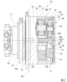
図2は、減速機付き流体モータ10の部分断面側面図である。
減速機付き流体モータ10は、建設機械1の本体部側に固定される固定ケーシング11と、固定ケーシング11に回転可能に支持された回転ケーシング12と、を備えている。回転ケーシング12は、略筒状に形成され、その外周面にスプロケット50が一体に取り付けられている。スプロケット50は、走行体3の被駆動部に連動可能に接続される。
FIG. 2 is a partial cross-sectional side view of the geared
The
固定ケーシング11には、図示しない流体モータ本体が内蔵されている。流体モータ本体は、例えば、斜板式のピストンモータ等によって構成されている。回転ケーシング12は、その内部の機構とともに減速機40の遊星歯車式減速部を構成している。遊星歯車式減速部40Aは、第1サンギヤ15、第1プラネタリギヤ16、回転キャリア17、第2サンギヤ19、第2プラネタリギヤ20、固定キャリア18、回転ケーシング12等を主要部品として備えている。減速機40は、流体モータ本体から入力された回転を所定の減速比に減速し、減速された回転をスプロケット50から走行体3の被駆動部に出力する。
The
回転ケーシング12は、固定ケーシング11の軸方向の一端側に図示しない軸受を介して回転可能に支持されている。回転ケーシング12の固定ケーシング11と逆側の軸方向の端部は、円板状のカバー部材21(端部カバー部)によって閉じられている。また、回転ケーシング12の内周面には、軸方向(モータ本体部の出力軸に沿う方向)に沿って延びる複数の内歯13が形成されている。本実施形態では、内歯13を備えた回転ケーシング12が遊星歯車式減速部のリングギヤを構成している。なお、リングギヤは、回転ケーシング12と別体部品として構成し、回転ケーシング12の内周面に固定するようにしても良い。
The rotating
第1サンギヤ15は、軸部15aとギヤ本体部15bとを有し、軸部15aがカップリング57を介して流体モータ本体の出力軸55に同軸に結合されている。ギヤ本体部15bの外周には外歯が形成されている。第1サンギヤ15は、流体モータ本体の出力軸55と一体に回転する。第1サンギヤ15のギヤ本体部15bは、回転ケーシング12の内側において、外歯が回転ケーシング12の内歯13に対向するように配置されている。第1サンギヤ15のギヤ本体部15bと回転ケーシング12の内周面の間には、周方向に等間隔に離間して複数の(例えば、三つの)第1プラネタリギヤ16が配置されている。各第1プラネタリギヤ16は外歯を有し、その外歯が第1サンギヤ15の外歯と、回転ケーシング12の内歯13とに噛み合っている。また、第1サンギヤ15のギヤ本体部15bは、軸部15aと逆側の軸方向の端部に円形状の膨出部15b-1が形成されている。膨出部15b-1は、ギヤ本体部15bの回転中心を中心とした中央領域において、カバー部材21の方向に向かって膨出し、カバー部材21に対向する端面15cが平坦に形成されている。
The
複数の第1プラネタリギヤ16は、共通の回転キャリア17によって回転可能に支持されている。回転キャリア17は、後に詳述する第2サンギヤ19を介して第1サンギヤ15の外周側に回転可能に配置されている。
The multiple first
回転キャリア17は、後述する第2サンギヤ19に一体回転可能に連結されるベースブロック17aを備え、そのベースブロック17aの軸心位置に第1サンギヤ15が挿通される挿通孔58が形成されている。挿通孔58の流体モータ本体側の内周縁部には、第2サンギヤ19のスプライン外歯と噛み合うスプライン内歯が形成されている。また、ベースブロック17aには、複数の第1プラネタリギヤ16が配置されるギヤ収容部が設けられるとともに、各第1プラネタリギヤ16を回転自在に支持する複数の(例えば、三つの)支持軸29が取り付けられている。各支持軸29は、第1サンギヤ15の軸部15aと平行になるようにベースブロック17aに取り付けられている。また、複数の支持軸29は、第1サンギヤ15の軸部15aを中心とした円周上に等間隔に離間して配置されている。各支持軸29は、対応する第1プラネタリギヤ16の軸孔に挿通され、軸受23を介して、対応する第1プラネタリギヤ16を回転可能に支持している。
The rotating
第2サンギヤ19は、その中心側領域に、第1サンギヤ15の軸部15aが挿通される挿通孔19aが形成されている。また、第2サンギヤ19の外周面には外歯19bが形成されている。外歯19bには、複数の(例えば、三つの)第2プラネタリギヤ20が噛み合っている。複数の第2プラネタリギヤ20は、固定キャリア18に取り付けられた支持軸39に回転可能に支持されている。固定キャリア18は、固定ケーシング11の軸方向の端部に一体に固定されている。また、各第2プラネタリギヤ20は、回転ケーシング12の内側において、回転ケーシング12の内歯13に噛み合っている。
The
上述のように第2サンギヤ19は、第1サンギヤ15の軸部15aの回りに回転可能に配置されているため、第1サンギヤ15のギヤ本体部15bから第1プラネタリギヤ16に一方向の回転が伝達されると、第1プラネタリギヤ16が回転ケーシング12の内歯13に噛み合って自転するとともに、第2サンギヤ19と一体となって第1サンギヤ15の回りを公転する。そして、このときの第2サンギヤ19の回転は、第2プラネタリギヤ20を介して回転ケーシング12に伝達される。この間に、第1サンギヤ15に伝達された駆動力は、所定の減速比に減速されて回転ケーシング12に伝達される。
なお、本実施形態では、第1サンギヤ15及び第1プラネタリギヤ16と、第2サンギヤ19及び第2プラネタリギヤ20が、回転ケーシング12の内歯13とともに遊星歯車式減速部を構成している。
As described above, the
In this embodiment, the
(第1実施形態)
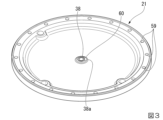
図3は、回転ケーシング12の端部に取り付けられる第1実施形態のカバー部材21を、回転ケーシング12の内部に臨む側(内側)から見た斜視図であり、図4は、図3の一部を拡大した斜視図である。
カバー部材21は、鋳鉄によって略円板状に形成されている。カバー部材21の外周縁部は肉厚に形成され、その肉厚部分に複数のボルト挿通孔59が形成されている。各ボルト挿通孔59には、図2に示すようにボルト53が挿通される。カバー部材21は、ボルト53によって回転ケーシング12の端面に締結固定される。
First Embodiment
FIG. 3 is an oblique view of the
The
鋳鉄から成るカバー部材21の回転ケーシング12の内部に臨む側の端面の中心位置には、第1サンギヤ15のギヤ本体部15bの端面15cに向かって突出する円形状の凸部38が形成されている。凸部38の端面38aは、ほぼ平坦に形成されている。凸部38の端面38aは、カバー部材21が回転ケーシング12に組付けられた状態において、第1サンギヤ15のギヤ本体部15bの端面15cと接触する。本実施形態の場合、凸部38の円形状の端面38aは、第1サンギヤ15の円形状の端面15cとほぼ同外径に形成されている。なお、本実施形態の場合、凸部38の端面38aは、サンギヤ(第1サンギヤ15)の端面15cに対向するカバー端面を構成している。また、凸部38の端面38aに接触する第1サンギヤ15は、カバー部材21の素材よりも硬度の高い鋼材によって形成されている。
At the center position of the end face of the
カバー部材21の凸部38の端面38aには、表面に硬化処理を施した表面硬化処理部60が配置されている。本実施形態では、表面硬化処理部60は、レーザー焼き入れによって端面38aの一部が焼き入れ処理されている。本実施形態の表面硬化処理部60は、レーザー焼き入れ処理部である。
カバー部材21は、プレス成形や型成形、切削加工等によって外形を造形された後に、凸部38の端面38aにレーザー焼き入れ処理(表面硬化処理)が施される。
A surface hardening
The
図4に拡大して示すように、本実施形態の表面硬化処理部60は、凸部38の端面38aの正面視において、端面38aの中心に向かって内径が次第に縮小する渦巻状に形成されている。本実施形態では、表面硬化処理部60の硬化処理としてレーザー焼き入れを採用しているため、凸部38の端面38aに形成される表面硬化処理部60は線状となる。このため、凸部38の端面38aには、線状の表面硬化処理部60が、その周囲の非硬化処理部61(レーザー焼き入れがされていない部分)と隣接して配置されている。また、凸部38の端面38aにレーザー焼き入れを施すと、レーザー焼き入れを施した部分は、非硬化処理部61に対して部分的に隆起する。このため、渦巻状の表面硬化処理部60は、非硬化処理部61に対して盛り上がっている。第1サンギヤ15の端面15cは、凸部38の端面38aの盛り上がった渦巻状の表面硬化処理部60に接触する。
また、本実施形態の渦巻状の表面硬化処理部60は、分岐部を持たない一本の線状に形成されている。
As shown in an enlarged view in FIG. 4, the
Moreover, the spiral surface hardening
ここで、回転ケーシング12の内部は、減速機40の内部の冷却と潤滑を行う作動油(潤滑油)が循環する構造とされている。回転ケーシング12の内部の作動油は、第1サンギヤ15の端面15cとカバー部材21の間にも回り込む。カバー部材21の凸部38の端面38aには、上述のように非硬化処理部61に隣接して表面硬化処理部60が盛り上がって形成されているため、凸部38の端面38aと第1サンギヤ15の端面15cの間には、非硬化処理部61によって相互に接触しない微小な隙間ができる。この微小な隙間には作動油が流入する。
The inside of the
以上のように、本実施形態の減速機40は、カバー部材21(端部カバー部)の第1サンギヤ15(サンギヤ)の端面15cに対向する凸部38の端面38a(カバー端面)に、表面に硬化処理を施した表面硬化処理部60が配置されている。これにより、カバー部材21の端面38aの第1サンギヤ15の端面15cと接触するする部分の硬度が高まる。このため、別体のスラストプレートを設けることなく、カバー部材21の端面38aの摩耗を抑制することができる。したがって、実施形態の減速機40を採用した場合には、部品点数の増加を抑制し、組付け作業を容易化することができる。
As described above, in the
また、本実施形態の減速機40では、表面硬化処理部60が比較的大型部品であるカバー部材21側の端面38aに配置されているため、カバー部材21の製造時に表面硬化処理を容易に施すことができる。特に、本実施形態のように第1サンギヤ15が鋼材等の硬度の高い材料から成り、カバー部材21が鋳鉄等の硬度の低い材料から成る場合には、第1サンギヤ15の端面15cと同等の硬度となるように、、カバー部材21の端面38aにレーザー焼き入れ等の表面硬化処理を施すだけで、減速機40の経時使用に伴うカバー部材21の摩耗を抑制することができる。したがって、本構成を採用した場合には、減速機40の製造の容易化と生産性の向上を図ることができる。
In addition, in the
なお、本実施形態の減速機40では、第1サンギヤ15が鋼材等の硬度の高い材料から成り、カバー部材21が鋳鉄等の硬度の低い材料から成るが、逆に、カバー部材21が硬度の高い材料から成り、第1サンギヤ15がカバー部材21よりも硬度の低い材料から成る場合には、第1サンギヤ15側の端面15cに表面硬化処理部60を設けることが有効となる。この場合、硬度の低い材料からなる第1サンギヤ15側の端面15cの摩耗を抑制することができる。
In the
また、本実施形態の減速機40は、カバー部材21(端部カバー部)の第1サンギヤ15の端面15cに対向する位置に凸部38が設けられている。このため、カバー部材21のうちの、第1サンギヤ15との接触部の剛性を高め、カバー部材21の変形やその変形に伴う異音の発生を抑制することができる。さらに、本実施形態では、凸部38の端面38aに表面硬化処理部60が配置され、第1サンギヤ15との接触部抵抗の低減が図られているため、カバー部材21の変形抑制効果と異音の発生抑制効果をより得ることができる。
さらに、本実施形態のように凸部38の端面38aの外径を、第1サンギヤ15の外歯の形成部よりも小径に形成しておけば、凸部38が第1サンギヤ15の外歯に接触することによる外歯の損傷を未然に防ぐことができる。
Moreover, in the
Furthermore, by forming the outer diameter of the
また、本実施形態の減速機40は、カバー部材21の凸部38の端面38aに、表面硬化処理部60が隣接する非硬化処理部61に対して盛り上がるように配置されている。このため、凸部38の端面38aと第1サンギヤ15の端面15cの間に作動油(潤滑油)が流入する。したがって、本実施形態の減速機40を採用した場合には、第1サンギヤ15とカバー部材21の接触部抵抗を作動油(潤滑油)によってより低減できるため、カバー部材21と第1サンギヤ15の接触部の摩耗をより抑制することができる。
In addition, in the
また、本実施形態の減速機40では、表面硬化処理部60がレーザー焼き入れによって形成されているため、表面硬化処理部60を対象部位に容易に形成することができる。特に、表面硬化処理部60の硬化処理としてレーザー焼き入れを採用した場合は、表面硬化処理部60を線状に所望の形状に形成することができ、しかも、表面硬化処理部60を非硬化処理部61に対して大きく盛り上がらせることができる。したがって、本実施形態の減速機40を採用した場合には、カバー部材21の端面38aと、第1サンギヤ15の端面15cの間の作動油(潤滑油)の流入挙動を容易に調整することができる。
In addition, in the
また、本実施形態の減速機40は、レーザー焼き入れによって形成される表面硬化処理部60が、分岐部を持たない連続した線状とされているため、表面硬化処理部60を連続して容易に形成することができる。
In addition, in the
(第2実施形態)
図5は、第2実施形態のカバー部材21の一部を拡大した図4と同様の斜視図である。
本実施形態では、第1実施形態と同様にカバー部材21の回転ケーシングの内部に臨む側の端面の中心位置に円形状の凸部38が形成されている。凸部38の平坦な端面38a(カバー端面)には、レーザー焼き入れによって表面硬化処理部60A(レーザー焼き入れ処理部)が形成されている。本実施形態の場合も、カバー部材21は、鋳鉄によって形成されている。
Second Embodiment
FIG. 5 is a perspective view similar to FIG. 4, in which a part of the
In this embodiment, as in the first embodiment, a
表面硬化処理部60Aは、凸部38の端面38aの正面視において、端面38aの中心62(第1サンギヤ(サンギヤ)の軸心と一致。)を中心とした放射状に配置されている。ただし、表面硬化処理部60Aは、全体が連続した線状に配置されるのではなく、直線的に延びる複数の線状部が放射状に配置されている。放射状に配置された複数の線状部は互いに交差しないように端面38aに配置されている。つまり、放射状に配置された複数の線状部は放射中心において相互に離間している。
When viewed from the front of the
本実施形態の減速機は、基本的な構成は第1実施形態のものと同様であるため、第1実施形態とほぼ同様の効果を得ることができる。ただし、本実施形態の減速機では、凸部38の端面38aに形成される表面硬化処理部60Aが、直線的に延びる複数の線状部から成り、その線状部が互いに交差しないように放射状に配置されているため、カバー部材21の端面38aと第1サンギヤの端面の間に作動油(潤滑油)を良好に流すことができる。すなわち、カバー部材21の端面38aの中心側に向かって作動油を表面硬化処理部60Aの線状部に沿って流すことができるうえ、端面38aの中心部の近傍に作動油が滞り難くなる。したがって、本実施形態の減速機を採用した場合には、カバー部材21と第1サンギヤの滑り接触部の抵抗と摩耗をより良好に抑制することができる。
The reducer of this embodiment has a basic configuration similar to that of the first embodiment, and therefore can achieve substantially the same effects as the first embodiment. However, in the reducer of this embodiment, the
また、本実施形態の減速機では、表面硬化処理部60Aの線状部が相互に交差しないように形成されているため、レーザー焼き入れがカバー部材21の端面38aの一部に一定の出力で複数回行われることによって、端面38aの一部に線状部の他の部分よりも盛り上がった部分が形成されることがない。したがって、本実施形態の構成を採用した場合には、表面硬化処理部60Aを第1リングギヤの端面に対して均一に接触させることができる。
In addition, in the reducer of this embodiment, the linear portions of the surface hardening
なお、本発明は上記の実施形態に限定されるものではなく、その要旨を逸脱しない範囲で種々の設計変更が可能である。
例えば、上記の実施形態では、カバー部材(端部カバー部)の端面にのみ表面硬化処理部が配置されているが、カバー部材(端部カバー部)の端面だけでなく、第1サンギヤの端面にも同様に表面硬化処理部を配置することも可能である。
The present invention is not limited to the above-described embodiment, and various design modifications are possible without departing from the spirit and scope of the present invention.
For example, in the above embodiment, the surface hardening treatment is arranged only on the end face of the cover member (end cover portion), but it is also possible to arrange a surface hardening treatment not only on the end face of the cover member (end cover portion) but also on the end face of the first sun gear.
また、第1実施形態では、カバー部材の端面に、一本の渦巻き状の線となるようにレーザー焼き入れによって表面硬化処理部が形成されているが、表面硬化処理部は二本以上の渦巻き状の線となるようにカバー部材や第1サンギヤの端面に形成しても良い。
また、第2実施形態では、カバー部材の端面に、放射状に配置された六本の線となるようにレーザー焼き入れによって表面硬化処理部が形成されているが、レーザー焼き入れによって形成される表面硬化処理部の線は六本に限らずに任意である。
さらに、カバー部材や第1サンギヤの端面に形成するレーザー焼き入れによる表面硬化処理部の形状は、第1実施形態や第2実施形態で示した形状に限定されるものではなく、例えば、ジグザグの折曲線のような形状や、同心円状に配置される径の異なる複数の円のような形状であっても良い。また、カバー部材や第1サンギヤの端面に形成するレーザー焼き入れによる表面硬化処理部の形状は、カバー部材や第1サンギヤの端面の中心に対して点対称な形状や線対称な形状だけでなく、非対称な形状であっても良い。
In addition, in the first embodiment, the surface hardening treatment is formed on the end face of the cover member by laser hardening so as to form a single spiral line, but the surface hardening treatment may be formed on the end face of the cover member or the first sun gear so as to form two or more spiral lines.
In addition, in the second embodiment, the surface hardening treatment is formed by laser hardening so as to form six radially arranged lines on the end face of the cover member, but the number of lines of the surface hardening treatment formed by laser hardening is not limited to six and can be any number.
Furthermore, the shapes of the surface hardening treatment portions formed on the end faces of the cover member and the first sun gear by laser hardening are not limited to the shapes shown in the first and second embodiments, and may be, for example, a shape such as a zigzag bend curve or a shape such as a plurality of circles of different diameters arranged concentrically. Moreover, the shapes of the surface hardening treatment portions formed on the end faces of the cover member and the first sun gear by laser hardening may be not only point-symmetric or line-symmetric with respect to the center of the end faces of the cover member and the first sun gear, but also asymmetric.
さらに、上記の各実施形態では、レーザー焼き入れによって表面硬化処理部が形成されているが、表面硬化処理部は、超音波焼き入れや、ショットピーニング、浸炭処理、溶射等の他の方法によって形成するようにしても良い。 Furthermore, in each of the above embodiments, the surface hardening treatment is formed by laser hardening, but the surface hardening treatment may be formed by other methods such as ultrasonic hardening, shot peening, carburizing, or thermal spraying.
また、上記の各実施形態の減速機は、第1サンギヤ及び第1プラネタリギヤと、第2サンギヤ及び第2プラネタリギヤを有する二段の遊星歯車式減速部を持つ構造とされているが、一段の遊星歯車式減速部を持つ構造であっても良い。
また、上記の各実施形態の減速機では、リングギヤ(内歯)を有する回転ケーシングの端部に別体のカバー部材(端部カバー部)が取り付けられた構造とされているが、端部カバーが回転ケーシングの軸方向の端部に一体に形成された構造であっても良い。
Furthermore, the reducer in each of the above embodiments is structured to have a two-stage planetary gear reduction section having a first sun gear and a first planetary gear, and a second sun gear and a second planetary gear, but it may also be structured to have a single-stage planetary gear reduction section.
In addition, in the reducer of each of the above embodiments, a separate cover member (end cover portion) is attached to the end of the rotating casing having the ring gear (internal teeth), but the end cover may be integrally formed with the axial end of the rotating casing.
1…建設機械、3…走行体、10…減速機付き流体モータ、15…第1サンギヤ(サンギヤ)、15c…端面、16…第1プラネタリギヤ(プラネタリギヤ)、21…カバー部材(端部カバー部)、38…凸部、38a…端面(カバー端面)、40…減速機、40A…遊星歯車式減速部、60,60A…表面硬化処理部、61…非硬化処理部。 1...construction machine, 3...traveling body, 10...fluid motor with reducer, 15...first sun gear (sun gear), 15c...end surface, 16...first planetary gear (planetary gear), 21...cover member (end cover portion), 38...projection, 38a...end surface (cover end surface), 40...reduction gear, 40A...planetary gear type reduction portion, 60, 60A...surface hardening treatment portion, 61...non-hardening treatment portion.
Claims (6)
前記遊星歯車式減速部の前記サンギヤの軸方向の端面に対向して配置される端部カバー部と、を備え、
前記端部カバー部の前記サンギヤの前記端面に対向するカバー端面と、前記サンギヤの前記端面の少なくともいずれか一方は、相互に接触する部位の表面に硬化処理を施した表面硬化処理部を有し、
前記表面硬化処理部は、表面にレーザー焼き入れを施したレーザー焼き入れ処理部であり、
前記レーザー焼き入れ処理部は、前記カバー端面と前記サンギヤの端面のいずれか一方の面に、前記サンギヤの軸心を中心とした放射状に配置された複数の線状部として構成されるとともに、放射状に配置された複数の前記線状部が放射中心において相互に離間して配置されることで、前記放射中心を含む領域に作動油の流動隙間を形成している減速機。 a planetary gear type reduction unit having a sun gear to which a driving force is input and a planetary gear meshing with the sun gear;
an end cover portion disposed opposite to an axial end face of the sun gear of the planetary gear type reduction unit,
At least one of a cover end surface of the end cover portion facing the end surface of the sun gear and the end surface of the sun gear has a surface hardening treatment portion in which a hardening treatment is applied to the surface of a portion where the end cover portion contacts the end surface of the sun gear,
The surface hardening treatment portion is a laser hardening treatment portion that performs laser hardening on the surface,
The laser hardening treatment portion is configured as a plurality of linear portions arranged radially around the axis of the sun gear on either the cover end face or the sun gear end face, and the plurality of radially arranged linear portions are arranged spaced apart from each other at the radial center , thereby forming a flow gap for hydraulic oil in a region including the radial center, thereby forming a reduction gear.
前記表面硬化処理部は、前記カバー端面のうちの前記凸部の端面に配置されている請求項2に記載の減速機。 The end cover portion has a protrusion that protrudes toward the end surface of the sun gear at a position facing the end surface,
The reducer according to claim 2 , wherein the surface hardening treatment portion is disposed on an end surface of the protruding portion of the cover end surface.
前記流体モータ本体の回転を減速して出力する減速機と、を備え、
前記減速機は、
駆動力が入力されるサンギヤ及び前記サンギヤに噛み合うプラネタリギヤを有する遊星歯車式減速部と、
前記遊星歯車式減速部の前記サンギヤの軸方向の端面に対向して配置される端部カバー部と、を備え、
前記端部カバー部の前記サンギヤの前記端面に対向するカバー端面と、前記サンギヤの前記端面の少なくともいずれか一方は、相互に接触する部位の表面に硬化処理を施した表面硬化処理部を有し、
前記表面硬化処理部は、表面にレーザー焼き入れを施したレーザー焼き入れ処理部であり、
前記レーザー焼き入れ処理部は、前記カバー端面と前記サンギヤの端面のいずれか一方の面に、前記サンギヤの軸心を中心とした放射状に配置された複数の線状部として構成されるとともに、放射状に配置された複数の前記線状部が放射中心において相互に離間して配置されることで、前記放射中心を含む領域に作動油の流動隙間を形成している減速機付き流体モータ。 A fluid motor body for generating a driving force;
a reducer for reducing the rotation speed of the fluid motor body and outputting the reduced rotation speed,
The reducer includes:
a planetary gear type reduction unit having a sun gear to which a driving force is input and a planetary gear meshing with the sun gear;
an end cover portion disposed opposite to an axial end face of the sun gear of the planetary gear type reduction unit,
At least one of a cover end surface of the end cover portion facing the end surface of the sun gear and the end surface of the sun gear has a surface hardening treatment portion in which a hardening treatment is applied to the surface of a portion where the end cover portion contacts the end surface of the sun gear,
The surface hardening treatment portion is a laser hardening treatment portion that performs laser hardening on the surface,
The laser hardening treatment is configured as a plurality of linear portions arranged radially around the axis of the sun gear on either the cover end face or the sun gear end face, and the plurality of radially arranged linear portions are arranged spaced apart from each other at the radial center , thereby forming a flow gap for hydraulic oil in a region including the radial center.A fluid motor with a reducer.
前記走行体を駆動する減速機付き流体モータと、を備え、
減速機付き流体モータは、
駆動力を発生する流体モータ本体と、
前記流体モータ本体の回転を減速して出力する減速機と、を備え、
前記減速機は、
駆動力が入力されるサンギヤ及び前記サンギヤに噛み合うプラネタリギヤを有する遊星歯車式減速部と、
前記遊星歯車式減速部の前記サンギヤの軸方向の端面に対向して配置される端部カバー部と、を備え、
前記端部カバー部の前記サンギヤの前記端面に対向するカバー端面と、前記サンギヤの前記端面の少なくともいずれか一方は、相互に接触する部位の表面に硬化処理を施した表面硬化処理部を有し、
前記表面硬化処理部は、表面にレーザー焼き入れを施したレーザー焼き入れ処理部であり、
前記レーザー焼き入れ処理部は、前記カバー端面と前記サンギヤの端面のいずれか一方の面に、前記サンギヤの軸心を中心とした放射状に配置された複数の線状部として構成されるとともに、放射状に配置された複数の前記線状部が放射中心において相互に離間して配置されることで、前記放射中心を含む領域に作動油の流動隙間を形成している建設機械。 A running body that runs on a road surface;
a fluid motor with a reducer for driving the running body,
Fluid motors with reducers are
A fluid motor body for generating a driving force;
a reducer for reducing the rotation speed of the fluid motor body and outputting the reduced rotation speed,
The reducer includes:
a planetary gear type reduction unit having a sun gear to which a driving force is input and a planetary gear meshing with the sun gear;
an end cover portion disposed opposite to an axial end face of the sun gear of the planetary gear type reduction unit,
At least one of a cover end surface of the end cover portion facing the end surface of the sun gear and the end surface of the sun gear has a surface hardening treatment portion in which a hardening treatment is applied to the surface of a portion where the end cover portion contacts the end surface of the sun gear,
The surface hardening treatment portion is a laser hardening treatment portion that performs laser hardening on the surface,
The laser hardening treatment portion is configured as a plurality of linear portions arranged radially around the axis of the sun gear on either the cover end face or the sun gear end face, and the plurality of radially arranged linear portions are arranged spaced apart from each other at the radial center , thereby forming a flow gap for hydraulic oil in an area including the radial center .
前記遊星歯車式減速部の前記サンギヤの軸方向の端面に対向して配置される端部カバー部と、を備えた減速機の製造方法であって、
表面硬化処理を施す対象となる前記端部カバー部と前記サンギヤの少なくとも一方を造形する工程と、
前記端部カバー部の前記サンギヤの前記端面に対向するカバー端面と、前記サンギヤの前記端面の少なくともいずれか一方に対し、前記カバー端面と前記サンギヤの前記端面の相互に接触する部位の表面にレーザー焼き入れ処理を施す工程と、を有し、
前記レーザー焼き入れ処理を施す工程では、前記カバー端面と前記サンギヤの端面のいずれか一方の面に、前記サンギヤの軸心を中心とした放射状に複数の線状部が現出し、かつ、放射状に配置された複数の前記線状部が放射中心において相互に離間することで、前記放射中心を含む領域に作動油の流動隙間が形成されるようにレーザー焼き入れを施す減速機の製造方法。 a planetary gear type reduction unit having a sun gear to which a driving force is input and a planetary gear meshing with the sun gear;
an end cover portion disposed opposite an axial end surface of the sun gear of the planetary gear type reduction section,
A step of shaping at least one of the end cover portion and the sun gear to be subjected to a surface hardening treatment;
and performing a laser hardening process on a surface of a portion where the cover end surface and the end surface of the sun gear contact each other, for at least one of a cover end surface of the end cover portion facing the end surface of the sun gear and the end surface of the sun gear,
A method for manufacturing a reducer in which laser hardening is performed in the process of performing the laser hardening treatment so that a plurality of linear portions appear radially from the axis of the sun gear on either the end face of the cover or the end face of the sun gear, and the radially arranged linear portions are spaced apart from each other at the radial center, thereby forming a flow gap for hydraulic oil in the area including the radial center .
Priority Applications (3)
| Application Number | Priority Date | Filing Date | Title |
|---|---|---|---|
| JP2020116066A JP7535397B2 (en) | 2020-07-06 | 2020-07-06 | Reducer, fluid motor with reducer, construction machine, and method for manufacturing reducer |
| KR1020210084446A KR20220005394A (en) | 2020-07-06 | 2021-06-29 | Speed reducer, fluid motor with speed reducer,construction machine and method for producing speed reducer |
| CN202110750193.2A CN113898702A (en) | 2020-07-06 | 2021-07-02 | Speed reducer, hydraulic motor, construction machine, and speed reducer manufacturing method |
Applications Claiming Priority (1)
| Application Number | Priority Date | Filing Date | Title |
|---|---|---|---|
| JP2020116066A JP7535397B2 (en) | 2020-07-06 | 2020-07-06 | Reducer, fluid motor with reducer, construction machine, and method for manufacturing reducer |
Publications (2)
| Publication Number | Publication Date |
|---|---|
| JP2022013986A JP2022013986A (en) | 2022-01-19 |
| JP7535397B2 true JP7535397B2 (en) | 2024-08-16 |
Family
ID=79187536
Family Applications (1)
| Application Number | Title | Priority Date | Filing Date |
|---|---|---|---|
| JP2020116066A Active JP7535397B2 (en) | 2020-07-06 | 2020-07-06 | Reducer, fluid motor with reducer, construction machine, and method for manufacturing reducer |
Country Status (3)
| Country | Link |
|---|---|
| JP (1) | JP7535397B2 (en) |
| KR (1) | KR20220005394A (en) |
| CN (1) | CN113898702A (en) |
Families Citing this family (1)
| Publication number | Priority date | Publication date | Assignee | Title |
|---|---|---|---|---|
| CN117758022A (en) * | 2023-12-21 | 2024-03-26 | 河南中原特钢装备制造有限公司 | High-pressure barrel zigzag thread laser quenching auxiliary equipment and quenching method |
Citations (3)
| Publication number | Priority date | Publication date | Assignee | Title |
|---|---|---|---|---|
| JP2000065164A (en) | 1998-08-13 | 2000-03-03 | Kubota Corp | Planetary gear set |
| JP2000507305A (en) | 1996-03-27 | 2000-06-13 | グリコ―メタル―ウエルケ・グリコ・ベー・ファウ・ウント・コンパニー・コマンディトゲゼルシャフト | Composite layer material and method for improving surface hardness of composite layer material |
| JP2007113768A (en) | 2005-10-24 | 2007-05-10 | Nidec-Shimpo Corp | Gear device |
Family Cites Families (7)
| Publication number | Priority date | Publication date | Assignee | Title |
|---|---|---|---|---|
| JPS5963258U (en) * | 1982-10-20 | 1984-04-25 | マツダ株式会社 | Differential gear casing |
| JPS6250023U (en) * | 1985-09-18 | 1987-03-27 | ||
| JPH0611405Y2 (en) * | 1989-05-29 | 1994-03-23 | 日立建機株式会社 | Planetary gear reducer |
| JP3686739B2 (en) | 1995-12-27 | 2005-08-24 | ナブテスコ株式会社 | Crawler drive unit |
| JPH1082430A (en) * | 1996-09-06 | 1998-03-31 | Tochigi Fuji Ind Co Ltd | Conical friction clutch, laser hardening method for conical surface thereof, and differential device using this conical friction clutch for differential limiting mechanism |
| CN107504136A (en) * | 2017-09-01 | 2017-12-22 | 广东星光传动股份有限公司 | One kind is without internal tooth planetary reducer |
| CN110725902A (en) * | 2019-09-19 | 2020-01-24 | 西安汇鑫传动控制有限责任公司 | Speed reducer for concrete mixer truck and application method thereof |
-
2020
- 2020-07-06 JP JP2020116066A patent/JP7535397B2/en active Active
-
2021
- 2021-06-29 KR KR1020210084446A patent/KR20220005394A/en active Pending
- 2021-07-02 CN CN202110750193.2A patent/CN113898702A/en active Pending
Patent Citations (3)
| Publication number | Priority date | Publication date | Assignee | Title |
|---|---|---|---|---|
| JP2000507305A (en) | 1996-03-27 | 2000-06-13 | グリコ―メタル―ウエルケ・グリコ・ベー・ファウ・ウント・コンパニー・コマンディトゲゼルシャフト | Composite layer material and method for improving surface hardness of composite layer material |
| JP2000065164A (en) | 1998-08-13 | 2000-03-03 | Kubota Corp | Planetary gear set |
| JP2007113768A (en) | 2005-10-24 | 2007-05-10 | Nidec-Shimpo Corp | Gear device |
Also Published As
| Publication number | Publication date |
|---|---|
| KR20220005394A (en) | 2022-01-13 |
| CN113898702A (en) | 2022-01-07 |
| JP2022013986A (en) | 2022-01-19 |
Similar Documents
| Publication | Publication Date | Title |
|---|---|---|
| JP3686739B2 (en) | Crawler drive unit | |
| CN101517264A (en) | Eccentric oscillating type speed reducer and stabilizer shaft rotating device using the same | |
| KR20070006729A (en) | Eccentric oscillation planetary gear device | |
| CN101328953B (en) | Eccentric oscillating planetary gear unit | |
| CN106895127B (en) | Differential gear | |
| TW201804099A (en) | Gear transmission device characterized in that the sliding bearing is applied to the bearing of gear transmission device to stably drive thereof | |
| JP2003088935A (en) | Manufacturing method of external gear | |
| JP7535397B2 (en) | Reducer, fluid motor with reducer, construction machine, and method for manufacturing reducer | |
| JP7005216B2 (en) | Gear support structure | |
| JP4732079B2 (en) | Decelerator | |
| JP7440218B2 (en) | Decelerator | |
| JP2023063961A (en) | Wave gear device, manufacturing method of wave gear device, joint device for robot, and gear component | |
| WO2018096941A1 (en) | Toroidal continuously variable transmission | |
| JP7731224B2 (en) | reducer | |
| JP7005217B2 (en) | Gear support structure | |
| JP4498823B2 (en) | Eccentric oscillation type planetary gear unit | |
| JP2009108996A (en) | Planetary gear device and vehicle transaxle | |
| JP2023063962A (en) | Wave gear device, manufacturing method of wave gear device, joint device for robot, and gear component | |
| JP2022181302A (en) | Power transmission device and manufacturing method of the same | |
| JP2023014479A (en) | Harmonic gear apparatus and actuator | |
| JP2008095724A (en) | Face gear and differential device using the same | |
| JP2008095774A (en) | Face gear transmission mechanism and differential device using the same | |
| JP2022012340A (en) | Speed reducer, hydraulic motor with speed reducer, construction machine, and manufacturing method of speed reducer | |
| JP7335390B1 (en) | Strain wave gearing, robot joints and gear parts | |
| JP6827752B2 (en) | Differential |
Legal Events
| Date | Code | Title | Description |
|---|---|---|---|
| A621 | Written request for application examination |
Free format text: JAPANESE INTERMEDIATE CODE: A621 Effective date: 20230601 |
|
| A977 | Report on retrieval |
Free format text: JAPANESE INTERMEDIATE CODE: A971007 Effective date: 20231222 |
|
| A131 | Notification of reasons for refusal |
Free format text: JAPANESE INTERMEDIATE CODE: A131 Effective date: 20240109 |
|
| A521 | Request for written amendment filed |
Free format text: JAPANESE INTERMEDIATE CODE: A523 Effective date: 20240308 |
|
| A131 | Notification of reasons for refusal |
Free format text: JAPANESE INTERMEDIATE CODE: A131 Effective date: 20240402 |
|
| A521 | Request for written amendment filed |
Free format text: JAPANESE INTERMEDIATE CODE: A523 Effective date: 20240603 |
|
| TRDD | Decision of grant or rejection written | ||
| A01 | Written decision to grant a patent or to grant a registration (utility model) |
Free format text: JAPANESE INTERMEDIATE CODE: A01 Effective date: 20240723 |
|
| A61 | First payment of annual fees (during grant procedure) |
Free format text: JAPANESE INTERMEDIATE CODE: A61 Effective date: 20240805 |
|
| R150 | Certificate of patent or registration of utility model |
Ref document number: 7535397 Country of ref document: JP Free format text: JAPANESE INTERMEDIATE CODE: R150 |
|
| S111 | Request for change of ownership or part of ownership |
Free format text: JAPANESE INTERMEDIATE CODE: R313111 |
|
| R350 | Written notification of registration of transfer |
Free format text: JAPANESE INTERMEDIATE CODE: R350 |