JP4732079B2 - Decelerator - Google Patents
Decelerator Download PDFInfo
- Publication number
- JP4732079B2 JP4732079B2 JP2005257763A JP2005257763A JP4732079B2 JP 4732079 B2 JP4732079 B2 JP 4732079B2 JP 2005257763 A JP2005257763 A JP 2005257763A JP 2005257763 A JP2005257763 A JP 2005257763A JP 4732079 B2 JP4732079 B2 JP 4732079B2
- Authority
- JP
- Japan
- Prior art keywords
- carrier
- planetary gear
- plate
- gear
- planetary
- Prior art date
- Legal status (The legal status is an assumption and is not a legal conclusion. Google has not performed a legal analysis and makes no representation as to the accuracy of the status listed.)
- Active
Links
Images


Classifications
-
- F—MECHANICAL ENGINEERING; LIGHTING; HEATING; WEAPONS; BLASTING
- F16—ENGINEERING ELEMENTS AND UNITS; GENERAL MEASURES FOR PRODUCING AND MAINTAINING EFFECTIVE FUNCTIONING OF MACHINES OR INSTALLATIONS; THERMAL INSULATION IN GENERAL
- F16H—GEARING
- F16H57/00—General details of gearing
- F16H57/08—General details of gearing of gearings with members having orbital motion
- F16H57/082—Planet carriers
Description
本発明は、太陽歯車と複数の遊星歯車とキャリアとを備える遊星歯車機構で入力軸の回転を減速して出力して回転ケーシングを駆動する遊星歯車減速機に関する。 The present invention relates to a planetary gear reducer that drives a rotating casing by decelerating and outputting the rotation of an input shaft by a planetary gear mechanism including a sun gear, a plurality of planetary gears, and a carrier.
従来、太陽歯車と複数の遊星歯車とキャリアとを備える遊星歯車機構で入力軸の回転を減速して出力して回転ケーシングを駆動する遊星歯車減速機に関し、遊星歯車をその一方側から片持ち状態で回転自在に保持するキャリアを備えるものが知られている(特許文献1参照)。そして、この特許文献1に記載された遊星歯車減速機では、遊星歯車を片持ち状態で保持してその遊星歯車の他方側に突出するキャリアの軸(片持ちピン部)の端部において遊星歯車の軸方向の移動が規制される構造になっている。また、遊星歯車減速機に関し、円板状の第1側板とこの第1側板から軸方向に延びる複数の脚部とこの脚部の先端に結合される円板状の第2側板とを備えて遊星歯車を保持するキャリアが設けられているものも知られている(特許文献2参照)。 Conventionally, a planetary gear reducer that drives a rotating casing by decelerating and outputting the rotation of an input shaft by a planetary gear mechanism including a sun gear, a plurality of planetary gears, and a carrier. And a carrier having a carrier that is held rotatably (see Patent Document 1). In the planetary gear speed reducer described in Patent Document 1, the planetary gear is held at the end of the carrier shaft (cantilever pin portion) that holds the planetary gear in a cantilever state and projects to the other side of the planetary gear. The movement in the axial direction is restricted. The planetary gear speed reducer includes a disk-shaped first side plate, a plurality of legs extending in the axial direction from the first side plate, and a disk-shaped second side plate coupled to the tip of the leg. There is also known one provided with a carrier for holding a planetary gear (see Patent Document 2).
特許文献1に記載された遊星歯車減速機のように遊星歯車を片持ち状態で保持するキャリアを用いると、両側とも保持する両持ちのキャリアよりも構造を簡素化することができる。しかし、この場合、遊星歯車を一方側から保持するため、キャリアの剛性が不足し易く、キャリアの変形を招いてしまい易いという問題がある。また、特許文献2に記載の遊星歯車減速機では、第1側板と第2側板とで遊星歯車を保持する機構であり、キャリアの剛性を高めることができるものの、遊星歯車を回転自在に保持するための歯車用の軸受が側板で覆われてしまうことになる。このため、この歯車用の軸受への潤滑油の供給不良を招き易く、軸受の損傷が生じ易くなってしまう虞がある。 When a carrier that holds the planetary gear in a cantilever state is used like the planetary gear speed reducer described in Patent Document 1, the structure can be simplified as compared to the both-sided carrier that holds both sides. However, in this case, since the planetary gear is held from one side, there is a problem that the rigidity of the carrier is likely to be insufficient and the carrier is likely to be deformed. Further, the planetary gear speed reducer described in Patent Document 2 is a mechanism that holds the planetary gear by the first side plate and the second side plate, and can increase the rigidity of the carrier, but holds the planetary gear rotatably. Therefore, the bearing for the gear for this will be covered with a side plate. For this reason, poor supply of lubricating oil to the gear bearing is likely to occur, and the bearing may be easily damaged.
本発明は、上記実情に鑑みることにより、遊星歯車を片持ち状態で保持するキャリアを備える遊星歯車減速機に関し、このキャリアの剛性を向上させることができるとともに、遊星歯車を回転自在に保持する歯車用の軸受への潤滑油供給不良を抑制することができる遊星歯車減速機を提供することを目的とする。 In view of the above circumstances, the present invention relates to a planetary gear speed reducer including a carrier that holds a planetary gear in a cantilever state. The present invention can improve the rigidity of the carrier, and the gear that rotatably holds the planetary gear. It is an object of the present invention to provide a planetary gear speed reducer that can suppress poor supply of lubricating oil to a conventional bearing.
本発明に係る遊星歯車減速機は、固定ケーシングに対してケーシング用の軸受を介して回転自在に保持される回転ケーシングと、前記回転ケーシングの内周に設けられている内歯と、回転自在に支持されるとともに、回転駆動力を発生させる駆動源に対して連結される入力軸と、前記入力軸に対して連結される太陽歯車と、前記太陽歯車と前記内歯との間に配置される複数の遊星歯車と、前記複数の遊星歯車をそれぞれその一方側から片持ち状態で歯車用の軸受を介して回転自在に保持するキャリアと、前記複数の遊星歯車をそれぞれ片持ち状態に保持して当該複数の遊星歯車の他方側にそれぞれ延びるように形成されている前記キャリアの軸の端部側に配置されて当該キャリアに連結されるとともに、当該キャリアのスラスト方向の荷重を保持するプレートと、を備えている遊星歯車減速機に関する。
そして、本発明に係る遊星歯車減速機は、上記目的を達成するために以下のようないくつかの特徴を有している。即ち、本発明の遊星歯車減速機は、以下の特徴を単独で、若しくは、適宜組み合わせて備えている。
A planetary gear speed reducer according to the present invention includes a rotating casing that is rotatably held with respect to a fixed casing via a bearing for the casing, an internal tooth provided on an inner periphery of the rotating casing, and a rotatable casing. An input shaft that is supported and connected to a drive source that generates a rotational driving force, a sun gear that is connected to the input shaft, and the sun gear that is disposed between the sun gear and the internal teeth. A plurality of planetary gears, a carrier for holding the plurality of planetary gears in a cantilevered state from one side of the planetary gears via a gear bearing, and holding the plurality of planetary gears in a cantilevered state. It is arranged on the end portion side of the shaft of the carrier formed so as to extend to the other side of each of the plurality of planetary gears, and is connected to the carrier, and the load in the thrust direction of the carrier is A plate lifting relates planetary reduction gear which comprises a.
The planetary gear speed reducer according to the present invention has several features as described below in order to achieve the above object. That is, the planetary gear speed reducer according to the present invention includes the following features alone or in combination.
上記目的を達成するための本発明に係る遊星歯車減速機における第1の特徴は、前記遊星歯車の他方側において前記歯車用の軸受の一部が露出する空間が設けられるように前記プレートが形成されていることである。 The first feature of the planetary gear speed reducer according to the present invention for achieving the above object is that the plate is formed so that a space for exposing a part of the gear bearing is exposed on the other side of the planetary gear. It has been done.
この構成によると、遊星歯車を片持ち状態で保持するキャリアにて遊星歯車の他方側に延びるように形成された軸の端部側に配置されたプレートが、キャリアに連結されている。このため、プレートで補強されることで、キャリアの剛性を高めて向上させることができる。そして、プレートには、遊星歯車を回転自在に保持する歯車用の軸受の一部が遊星歯車の他方側において露出する空間が設けられているため、潤滑油切れを生じさせることなく歯車用の軸受へ潤滑油を供給することができる。したがって、本発明の遊星歯車減速機によると、キャリアの剛性を向上させることができるとともに、歯車用の軸受への潤滑油供給不良を抑制することができる。 According to this configuration, the plate disposed on the end side of the shaft formed to extend to the other side of the planetary gear by the carrier that holds the planetary gear in a cantilever state is connected to the carrier. For this reason, the rigidity of a carrier can be raised and improved by being reinforced with a plate. Since the plate is provided with a space in which a part of the bearing for the gear that rotatably holds the planetary gear is exposed on the other side of the planetary gear, the gear bearing without causing the lubricating oil to run out. Lubricating oil can be supplied. Therefore, according to the planetary gear speed reducer of the present invention, it is possible to improve the rigidity of the carrier and to suppress the poor supply of lubricating oil to the gear bearing.
また、本発明に係る遊星歯車減速機における第2の特徴は、前記複数の遊星歯車をそれぞれ保持する前記キャリアの前記各軸の端部に形成された凸部と、前記プレートに形成されて前記各凸部にそれぞれ嵌合する嵌合孔と、が更に備えられ、前記凸部は、前記キャリアの径方向における中心の位置からの径方向距離が一定の位置に設けられていることである。 The second feature of the planetary gear speed reducer according to the present invention is that the projecting portion formed on the end of each shaft of the carrier that holds the plurality of planetary gears, and the plate, A fitting hole that fits into each of the convex portions, and the convex portion is provided at a position where a radial distance from a center position in a radial direction of the carrier is constant.
この構成によると、キャリアの各軸の端部に形成された凸部が、プレートに形成された嵌合孔に嵌合することで、プレートがキャリアに連結されることになる。そして、プレートの嵌合孔に嵌合するキャリアの各軸端部の凸部は、キャリアの中心から径方向距離が一定の位置に設けられている。このため、プレートが適用されるキャリアが異なるものであっても、共通のプレートを用いることが可能になる。すなわち、キャリアの大きさによらず、プレートの共通化を図って、製造の効率化を図ることができる。 According to this structure, the convex part formed in the edge part of each axis | shaft of a carrier fits in the fitting hole formed in the plate, and a plate will be connected with a carrier. And the convex part of each axial end part of the carrier fitted in the fitting hole of the plate is provided at a position where the radial distance from the center of the carrier is constant. For this reason, even if the carrier to which the plate is applied is different, a common plate can be used. In other words, the plate can be shared regardless of the size of the carrier, and the manufacturing efficiency can be improved.
また、本発明に係る遊星歯車減速機における第3の特徴は、前記空間として、前記プレートの周縁部分が一部切り欠かれた状態に形成されている切欠き部を備えていることである。 A third feature of the planetary gear speed reducer according to the present invention is that the space includes a notch formed in a state in which a peripheral portion of the plate is partially cut away.
この構成によると、プレートの周縁部分に一部切り欠かれた状態に形成された切欠き部を設けることで、歯車用の軸受の一部が露出する空間を簡易な機構で容易に形成することができる。 According to this configuration, by providing a notch portion formed in a partially cutout state at the peripheral edge portion of the plate, a space where a part of the gear bearing is exposed can be easily formed with a simple mechanism. Can do.
また、本発明に係る遊星歯車減速機における第4の特徴は、前記空間として、前記プレートにおいて前記歯車用の軸受に対向する位置において形成されている孔を備えていることである。 A fourth feature of the planetary gear speed reducer according to the present invention is that the space includes a hole formed at a position facing the gear bearing in the plate.
この構成によると、プレートに対して歯車用の軸受に対向する位置に孔を設けることで、歯車用の軸受の一部が露出する空間を簡易な機構で容易に形成することができる。 According to this configuration, by providing the hole at a position facing the gear bearing with respect to the plate, a space in which a part of the gear bearing is exposed can be easily formed with a simple mechanism.
以下、本発明を実施するための最良の形態について図面を参照しつつ説明する。本発明は、太陽歯車と複数の遊星歯車とキャリアとを備える遊星歯車機構で入力軸の回転を減速して出力して回転ケーシングを駆動する遊星歯車減速機に関して、広く適用することができる。例えば、建設機械に備えられる走行用装置における減速機などとして用いることができるが、その用途に限らず、より広範な用途に対して適用でき、多くの異なる環境および各種の目的に応じて適用することができる。なお、以下の説明においては、第1乃至第3実施形態に分けて説明する。 Hereinafter, the best mode for carrying out the present invention will be described with reference to the drawings. The present invention can be widely applied to a planetary gear reducer that drives a rotating casing by decelerating and outputting the rotation of an input shaft by a planetary gear mechanism including a sun gear, a plurality of planetary gears, and a carrier. For example, it can be used as a speed reducer or the like in a traveling device provided in a construction machine, but is not limited to its application, and can be applied to a wider range of applications, and applied according to many different environments and various purposes. be able to. In the following description, the description will be divided into the first to third embodiments.
(第1実施形態)
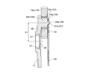
図1は、本発明の第1実施形態に係る遊星歯車減速機1を示す断面図である。図1に示す遊星歯車減速機1は、図示しない建設機械に備えられており、この建設機械を走行させるための油圧モータ10が内部に配設された固定ケーシング11に対して取り付けられている。この遊星歯車減速機1は、回転ケーシング12、内歯13、入力軸14、太陽歯車15、遊星歯車16、キャリア17、プレート18、第2太陽歯車19、第2遊星歯車20などを備えて構成されている。そして、遊星歯車減速機1は、油圧モータ10で発生する回転駆動力を減速して伝達し、最終的に回転ケーシング12を回転駆動することで、回転ケーシング12に設けられたフランジ部30に取り付けられた図示しないスプロケットを介して図示しない被駆動部を駆動する。
(First embodiment)
FIG. 1 is a cross-sectional view showing a planetary gear speed reducer 1 according to the first embodiment of the present invention. A planetary gear speed reducer 1 shown in FIG. 1 is provided in a construction machine (not shown), and a
遊星歯車減速機1における回転ケーシング12は、中空円筒状の基本構造をもつように形成されており、その一方の側の開口部から固定ケーシング11の端部が挿入されるように配設される。なお、回転ケーシング12の他方の側の開口部は、蓋体21によって閉じられた状態になっている。この回転ケーシング12は、固定ケーシング11に対してケーシング用の軸受28(28a、28b)を介して回転自在に保持されている。すなわち、回転ケーシング12は、内周に形成された突条部31が固定ケーシング11の外周に取り付けられた2つの軸受28aおよび28bによって挟持されることで、軸受28を介して固定ケーシング11に回転自在に保持されるようになっている。また、内歯13は、回転ケーシング12の内周に設けられており(回転ケーシング12と一体に形成されていても、別体に形成されて回転ケーシング12に取り付けられていても、いずれでもよい)、後述する遊星歯車16や第2遊星歯車20と噛合するようになっている。
The rotating
入力軸14は、回転ケーシング12内の中心に配置されており、回転自在に支持されている。そして、この入力軸14は、回転駆動力を発生させる駆動源である油圧モータ10に対して連結されている。すなわち、入力軸14は、油圧モータ10のモータ出力軸32とカップリング33を介して連結されており、モータ出力軸32とともに回転するようになっている。
The input shaft 14 is disposed at the center in the
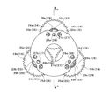
太陽歯車15は、入力軸14の端部に連結されており、遊星歯車16と噛合するように配設されている。また、遊星歯車16は、複数設けられており、太陽歯車15と内歯13との間に配置されている。すなわち、遊星歯車16は、太陽歯車15と内歯13とのいずれにも噛合しており、太陽歯車15の自転にともなって回転駆動されて太陽歯車15の周りを公転するように配設されている。図2は、図1のII−II線矢視位置から見た遊星歯車16、プレート18、キャリア17の一部等を示した図である。この図2に示すように、遊星歯車16は3個配設されており、この3個の遊星歯車16(16a、16b、16c)はそれらの各中心位置が同一円上で周方向に例えば均等角度(120度)ずれて順番に配置された状態になっている。
The sun gear 15 is connected to the end of the input shaft 14 and is disposed so as to mesh with the
図3は、図2のIII−III線矢視位置に対応する断面図であって、遊星歯車16、プレート18、およびキャリア17等を示す図である。キャリア17は、図3に示すように、遊星歯車16を保持する遊星枠を構成しており、複数の遊星歯車16をそれぞれその一方側から片持ち状態で歯車用の軸受23(23a、23b、23c)を介して回転自在に保持している。すなわち、このキャリア17には、図1乃至図3に示すように、各遊星歯車16(16a、16b、16c)をそれぞれ片持ち状態で回転自在に保持してその各遊星歯車16の他方側にそれぞれ突出する(他方側にそれぞれ延びるように形成されている)複数の軸29(29a、29b、29c)が、キャリア17の外周に沿って周方向均等位置における3箇所に設けられている。なお、各軸29の端部には、後述するプレート18を連結するための凸部26(26a、26b、16c)が形成されている。また、キャリア17には、各軸29が形成されている平板状の部分35の径方向中心部において中空部分36が形成されており、この中空部分36には周方向に第2太陽歯車19の端部とスプライン結合される内歯部分37が形成されている。
FIG. 3 is a cross-sectional view corresponding to the position taken along the line III-III in FIG. 2 and shows the
第2太陽歯車19は、図1に示すように、入力軸14およびカップリング33が内挿される円筒形状に形成されており、その外周に外歯が形成されている。この外歯には、キャリア17における内歯部分37が前述のスプライン結合されるとともに、複数個(3個)の第2遊星歯車20が噛合している。第2遊星歯車20は、固定ケーシング11の端面においてその外周に沿って周方向均等位置の3箇所に設けられている突設軸部34に対して回転自在に支持されている。
As shown in FIG. 1, the second sun gear 19 is formed in a cylindrical shape in which the input shaft 14 and the
プレート18は、図1乃至図3に示すように、キャリア17における複数の軸29の端部側に配置されて各軸29の端部に対してそれぞれ連結されているとともに、キャリア17のスラスト方向の荷重を保持するように配設されている。このプレート18は、略円板状に形成されている。そして、プレート18は、その中心に太陽歯車15との干渉を防止するための中心孔が形成されるとともに、キャリア17の各軸29(29a、29b、29c)の端部の凸部26(26a、26b、26c)にそれぞれ嵌合する嵌合孔27(27a、27b、27c)が形成されている。なお、プレート18は、その嵌合孔27に各軸29の凸部26が嵌合した状態で、回転ケーシング12の端部に取り付けられている蓋部21に設けられた複数の突起部22によって押圧されることで、スラスト方向の荷重が支持されるようになっている。
As shown in FIGS. 1 to 3, the
また、プレート18は、遊星歯車16の他方側において歯車用の軸受23(23a、23b、23c)がそれぞれ一部露出する空間が設けられるように形成されている。すなわち、プレート18には、歯車用の軸受23の一部を露出させるための空間として、切欠き部24と孔25とが備えられている。
The
切欠き部24は、プレート18の周縁部分が一部切り欠かれた状態に形成されており、遊星歯車16aに対向する位置に切欠き部24aが、遊星歯車16bに対向する位置に切欠き部24bが、遊星歯車16cに対向する位置に切欠き部24cが、それぞれ設けられている。また、孔25は、プレート18において各歯車用の軸受23に対向する位置に形成されており、嵌合孔26aの両側であって軸受23aに対向する位置に孔25a及び25bが、嵌合孔26bの両側であって軸受23bに対向する位置に孔25c及び25dが、嵌合孔26cの両側であって軸受23cに対向する位置に孔25e及び25fが、それぞれ形成されている。
The
次に、この遊星歯車減速機1の作動について説明する。固定ケーシング11内に配設された油圧モータ10が回転すると、その回転駆動力が、モータ出力軸32とともに回転するように連結された入力軸14へと伝達される。そして、入力軸14の回転とともに太陽歯車15が回転して、この太陽歯車15に噛合している遊星歯車16が内歯13と噛合しながら太陽歯車15の周りで公転運動を行うことになる。この遊星歯車16の公転運動に伴ってキャリア17が回転し、キャリア17の内歯部分とスプライン結合された第2太陽歯車19が回転する。この第2太陽歯車19が回転することで、固定ケーシング11の各突設軸部34に回転自在に支持された各第2遊星歯車20が回転し、これにより、第2遊星歯車20と内歯13との噛合を介して、回転ケーシング12が回転駆動されるようになっている。
Next, the operation of the planetary gear speed reducer 1 will be described. When the
また、回転ケーシング12の内部では、遊星歯車減速機1における冷却用や潤滑用の目的のために、油圧モータ10の作動油が一部循環されるようになっている。そして、遊星歯車減速機1の上述の作動に伴って、この作動油(潤滑油)が、プレート18に形成された切欠き部24や孔25を介して流動して、歯車用の軸受23に供給されるようになっている。
Further, inside the
以上説明した第1実施形態に係る遊星歯車減速機1によると、遊星歯車16を片持ち状態で保持するキャリア17にて遊星歯車16の他方側に延びるように形成された軸29の端部側に配置されたプレート18が、キャリア17に連結されている。このため、プレート18で補強されることで、キャリア17の剛性を高めて向上させることができる。そして、プレート18には、遊星歯車16を回転自在に保持する歯車用の軸受23の一部が遊星歯車16の他方側において露出する空間(24、25)が設けられているため、潤滑油切れを生じさせることなく歯車用の軸受23へ潤滑油を供給することができる。したがって、この遊星歯車減速機1によると、キャリア17の剛性を向上させることができるとともに、歯車用の軸受23への潤滑油供給不良を抑制することができる。
According to the planetary gear speed reducer 1 according to the first embodiment described above, the end portion side of the
また、遊星歯車減速機1によると、プレート18の周縁部分に一部切り欠かれた状態に形成された切欠き部24を設けることで、歯車用の軸受23の一部が露出する空間を簡易な機構で容易に形成することができる。また、プレート18に対して歯車用の軸受23に対向する位置に孔25を設けることでも、歯車用の軸受23の一部が露出する空間を簡易な機構で容易に形成することができる。
Further, according to the planetary gear speed reducer 1, by providing the
(第2実施形態)
次に、本発明の第2実施形態に係る遊星歯車減速機について説明する。第2実施形態に係る遊星歯車減速機は、第1実施形態の場合と同様に構成されており、図1に示す遊星歯車減速機1と同様の構成を有する回転ケーシング12、内歯13、入力軸14、太陽歯車15、遊星歯車16、プレート18などを備えている。しかし、第2実施形態の遊星歯車減速機としての径方向寸法である回転ケーシング12の径方向寸法が、第1実施形態の遊星歯車減速機1の場合よりも小さくなっている。
(Second Embodiment)
Next, a planetary gear reducer according to a second embodiment of the present invention will be described. The planetary gear speed reducer according to the second embodiment is configured in the same manner as in the first embodiment, and has the same configuration as the planetary gear speed reducer 1 shown in FIG. A shaft 14, a sun gear 15, a
図4は、第2実施形態に係る遊星歯車減速機における遊星歯車16、プレート18、キャリア40の断面図であって、第1実施形態における図3に対応する図である。第2実施形態の遊星歯車減速機では、遊星歯車減速機1に対して、径方向寸法が小さくなっているため、遊星歯車16の径方向寸法が小さくなるとともにキャリア40の径方向寸法も小さく形成されている。
FIG. 4 is a cross-sectional view of the
また、図4に示すように、キャリア40は、遊星歯車減速機1におけるキャリア17と同様に、軸29(29a、29b、29c)、凸部26(26a、26b、26c)、平板状の部分35、中空部分36、内歯部分37を備えて構成されている。しかし、キャリア17では凸部26が軸29の端部の径方向中心位置に配置されていたのに対して、キャリア40では凸部26が軸29の端部の径方向中心からずれた位置に配置されている。そして、キャリア40における凸部26のキャリア40の径方向の中心位置に対する配置寸法である径方向距離L2(図4参照)は、キャリア17における凸部26のキャリア17の径方向の中心位置からの配置寸法である径方向距離L1(図3参照)と同じになるように設定されている。すなわち、キャリア40およびキャリア17において、凸部26は、キャリアの径方向における中心の位置からの径方向距離が一定の位置になるように設けられている。
As shown in FIG. 4, the
このように、第1実施形態および第2実施形態に係る遊星歯車減速機では、キャリア(17、40)の各軸29の端部に形成されてプレート18に形成された嵌合孔27に嵌合する凸部26が、キャリア(17、40)の中心から径方向距離(L1、L2)が一定の位置に設けられている。このため、プレート18が適用されるキャリアが異なるものであっても、共通のプレート18を用いることが可能になる。すなわち、キャリアの大きさによらず、プレートの共通化を図って、製造の効率化を図ることができる。
Thus, in the planetary gear speed reducer according to the first embodiment and the second embodiment, it is fitted into the fitting holes 27 formed in the end portions of the
(第3実施形態)
次に、本発明の第3実施形態に係る遊星歯車減速機について説明する。第3実施形態に係る遊星歯車減速機は、第1実施形態の場合と同様に構成されており、図1に示す遊星歯車減速機1と同様の構成を有する回転ケーシング12、内歯13、入力軸14、太陽歯車15、遊星歯車16などを備えている。しかし、キャリアへプレートを連結する形態が、第1実施形態の遊星歯車減速機1とは異なっている。
(Third embodiment)
Next, a planetary gear reducer according to a third embodiment of the invention will be described. The planetary gear speed reducer according to the third embodiment is configured in the same manner as in the first embodiment, and has the same configuration as the planetary gear speed reducer 1 shown in FIG. A shaft 14, a sun gear 15, a
図5は、第3実施形態に係る遊星歯車16、プレート42、キャリア41の一部等を示す図であって、第1実施形態における図2に対応する図である。また、図6は、図5のVI−VI線矢視位置に対応する断面図であって、遊星歯車16、キャリア41、プレート42等を示す図である。図5および図6に示すように、キャリア41には、各遊星歯車16(16a、16b、16c)をそれぞれその一方側から片持ち状態で歯車用の軸受23(23a、23b、23c)を介して回転自在に保持してその各遊星歯車16の他方側にそれぞれ延びるように形成されている軸29(29a、29b、29c)が、キャリア41の外周に沿って周方向均等位置における3箇所に設けられている。しかし、キャリア41の各軸29には、凸部は設けられていない。
FIG. 5 is a diagram illustrating a part of the
また、キャリア41には、図5および図6に示すように、プレート42を連結するための突設部43(43a、43b、43c)が、隣り合う軸29・29の中間位置であってキャリア41の周方向に沿った3箇所の位置に設けられている。すなわち、各軸29と各突設部43とが、交互に並んだ状態でキャリア41の外周に沿って周方向均等位置にそれぞれ配置されるように設けられている。そして、各突設部43には、ボルト孔46がそれぞれ形成されている。
Further, as shown in FIGS. 5 and 6, the
また、図5および図6に示すように、プレート42は、第1実施形態のプレート18と同様に円板状に形成されているとともに、歯車用の軸受23(23a、23b、23c)の一部を露出させる空間としての切欠き部24(24a、24b、24c)が設けられている。すなわち、プレート42には、その周縁部分が一部切り欠かれた状態に形成された各切欠き部24が、各歯車用の軸受29に対向する位置にそれぞれ設けられている。なお、プレート42には、第1実施形態のプレート18のような軸受露出用の空間としての孔は設けられていない。
Further, as shown in FIGS. 5 and 6, the
また、プレート42には、キャリア41への連結用のボルト44(44a、44b、44c)が挿通される貫通孔45が3箇所に形成されている。この各貫通孔45は、キャリア41の各突設部43に対応する位置に設けられている。そして、各ボルト44がプレート42の各貫通孔45に対して挿通されるとともに、キャリア41の各突設部43に設けられた各ボルト孔46にそれぞれ螺合することによって、プレート42がキャリア41に対して連結されるようになっている。
The
上述した第3実施形態では、第1実施形態のように軸29でプレート42が連結されるのではなく、突設部43でプレート42がキャリア41に連結されるようになっている。このように、プレート42で補強されることで、キャリア41の剛性を高めて向上させることができる。そして、プレート42には、歯車用の軸受23の一部を露出させる空間である切欠き部24が設けられているため、潤滑油切れを生じさせることなく歯車用の軸受23へ潤滑油を供給することができる。したがって、第3実施形態の遊星歯車減速機によると、第1実施形態の場合と同様に、キャリア41の剛性を向上させることができるとともに、歯車用の軸受23への潤滑油供給不良を抑制することができる。
In the third embodiment described above, the
以上、第1乃至第3実施形態を例にとって本発明の実施形態について説明したが、本発明は上述の実施の形態に限られるものではなく、特許請求の範囲に記載した限りにおいて様々に変更して実施することができる。例えば、キャリアにて回転自在に支持される遊星歯車は、2個であっても4個以上であってもよい。また、歯車用の軸受を露出させる空間としては、切欠き部や孔以外の形態であってもよい。 The embodiments of the present invention have been described above by taking the first to third embodiments as examples. However, the present invention is not limited to the above-described embodiments, and various modifications can be made as long as they are described in the claims. Can be implemented. For example, the number of planetary gears rotatably supported by the carrier may be two or four or more. Further, the space for exposing the gear bearing may be in a form other than a notch or a hole.
1 遊星歯車減速機
11 固定ケーシング
12 回転ケーシング
13 内歯
14 入力軸
15 太陽歯車
16 遊星歯車
17 キャリア
18 プレート
23、23a、23b、23c 歯車用の軸受
24、24a、24b、24c 切欠き部(空間)
25、25a、25b、25c、25d、25e、25f 孔(空間)
26、26a、26b、26c 凸部
27、27a、27b、27c 嵌合孔
29、29a、29b、29c 軸
DESCRIPTION OF SYMBOLS 1
25, 25a, 25b, 25c, 25d, 25e, 25f Hole (space)
26, 26a, 26b,
Claims (3)
前記回転ケーシングの内周に設けられている内歯と、
回転自在に支持されるとともに、回転駆動力を発生させる駆動源に対して連結される入力軸と、
前記入力軸に対して連結される太陽歯車と、
前記太陽歯車と前記内歯との間に配置される複数の遊星歯車と、
前記複数の遊星歯車をそれぞれその一方側から片持ち状態で歯車用の軸受を介して回転自在に保持するキャリアと、
前記複数の遊星歯車をそれぞれ片持ち状態に保持して当該複数の遊星歯車の他方側にそれぞれ延びるように形成されている前記キャリアの軸の端部側に配置されて当該キャリアに連結されるとともに、当該キャリアのスラスト方向の荷重を保持するプレートと、
を備えている遊星歯車減速機であって、
前記遊星歯車の他方側において前記歯車用の軸受の一部が露出する空間が設けられるように前記プレートが形成されており、
前記複数の遊星歯車をそれぞれ保持する前記キャリアの前記各軸の端部に形成された凸部と、
前記プレートに形成されて前記各凸部にそれぞれ嵌合する嵌合孔と、
が更に備えられ、
前記凸部は、前記キャリアの径方向における中心の位置からの径方向距離が一定の位置に設けられていることを特徴とする遊星歯車減速機。 A rotating casing that is held rotatably via a bearing for the casing with respect to the fixed casing;
Internal teeth provided on the inner periphery of the rotating casing;
An input shaft that is rotatably supported and connected to a drive source that generates a rotational drive force;
A sun gear coupled to the input shaft;
A plurality of planetary gears disposed between the sun gear and the internal teeth;
A carrier for rotatably holding the plurality of planetary gears in a cantilevered state from one side thereof via a gear bearing;
The plurality of planetary gears are held in a cantilever state and arranged on the end side of the shaft of the carrier formed to extend to the other side of the plurality of planetary gears, and are connected to the carrier. A plate that holds the load in the thrust direction of the carrier;
A planetary gear reducer comprising:
The plate is formed so as to provide a space where a part of the bearing for the gear is exposed on the other side of the planetary gear ;
A convex portion formed at an end of each axis of the carrier for holding each of the plurality of planetary gears;
A fitting hole formed in the plate and fitted into each of the convex portions;
Is further provided,
The planetary gear speed reducer , wherein the convex portion is provided at a position where a radial distance from a center position in a radial direction of the carrier is constant .
Priority Applications (1)
| Application Number | Priority Date | Filing Date | Title |
|---|---|---|---|
| JP2005257763A JP4732079B2 (en) | 2005-09-06 | 2005-09-06 | Decelerator |
Applications Claiming Priority (1)
| Application Number | Priority Date | Filing Date | Title |
|---|---|---|---|
| JP2005257763A JP4732079B2 (en) | 2005-09-06 | 2005-09-06 | Decelerator |
Publications (2)
| Publication Number | Publication Date |
|---|---|
| JP2007071273A JP2007071273A (en) | 2007-03-22 |
| JP4732079B2 true JP4732079B2 (en) | 2011-07-27 |
Family
ID=37932909
Family Applications (1)
| Application Number | Title | Priority Date | Filing Date |
|---|---|---|---|
| JP2005257763A Active JP4732079B2 (en) | 2005-09-06 | 2005-09-06 | Decelerator |
Country Status (1)
| Country | Link |
|---|---|
| JP (1) | JP4732079B2 (en) |
Families Citing this family (10)
| Publication number | Priority date | Publication date | Assignee | Title |
|---|---|---|---|---|
| KR101161484B1 (en) | 2010-02-12 | 2012-07-02 | 미츠비시 쥬고교 가부시키가이샤 | Gear box for wind turbine generator and wind turbine generator |
| KR101240894B1 (en) * | 2010-09-30 | 2013-03-11 | 주식회사 만도 | Electric disc brake |
| JP2013104548A (en) * | 2011-11-17 | 2013-05-30 | Asano Gear Co Ltd | Planetary gear device |
| ES2587879T3 (en) | 2013-02-22 | 2016-10-27 | Moventas Gears Oy | A satellite carrier for a planetary gear |
| EP2770230B1 (en) | 2013-02-22 | 2016-02-17 | Moventas Gears Oy | A planet wheel carrier for a planetary gear |
| KR101505414B1 (en) | 2013-08-26 | 2015-03-26 | 티아이씨(주) | End-cover for reducer |
| JP6482809B2 (en) * | 2014-09-29 | 2019-03-13 | 日本電産シンポ株式会社 | Transmission and drive device |
| JP6833428B2 (en) * | 2016-09-26 | 2021-02-24 | ナブテスコ株式会社 | Decelerator |
| CN106382354A (en) * | 2016-10-21 | 2017-02-08 | 张玉国 | High-speed large-torque longitudinal shaft-connecting speed reducer |
| JP2022012340A (en) | 2020-07-01 | 2022-01-17 | ナブテスコ株式会社 | Speed reducer, hydraulic motor with speed reducer, construction machine, and manufacturing method of speed reducer |
Citations (3)
| Publication number | Priority date | Publication date | Assignee | Title |
|---|---|---|---|---|
| JPH08145151A (en) * | 1994-11-16 | 1996-06-04 | Toyota Motor Corp | Parallel shaft differential gear |
| JPH09269036A (en) * | 1996-03-29 | 1997-10-14 | Kayaba Ind Co Ltd | Planetary gear deceleration device |
| JP2000193072A (en) * | 1998-10-21 | 2000-07-14 | Tochigi Fuji Ind Co Ltd | Power transmission device and differential device |
-
2005
- 2005-09-06 JP JP2005257763A patent/JP4732079B2/en active Active
Patent Citations (3)
| Publication number | Priority date | Publication date | Assignee | Title |
|---|---|---|---|---|
| JPH08145151A (en) * | 1994-11-16 | 1996-06-04 | Toyota Motor Corp | Parallel shaft differential gear |
| JPH09269036A (en) * | 1996-03-29 | 1997-10-14 | Kayaba Ind Co Ltd | Planetary gear deceleration device |
| JP2000193072A (en) * | 1998-10-21 | 2000-07-14 | Tochigi Fuji Ind Co Ltd | Power transmission device and differential device |
Also Published As
| Publication number | Publication date |
|---|---|
| JP2007071273A (en) | 2007-03-22 |
Similar Documents
| Publication | Publication Date | Title |
|---|---|---|
| JP4732079B2 (en) | Decelerator | |
| JP4590299B2 (en) | Carrier support structure for planetary gear reducer | |
| JP6606328B2 (en) | Reduction mechanism and drive unit with reduction gear | |
| JP4694899B2 (en) | Reduction gear bearing preload mechanism | |
| JP2006275258A (en) | Sprocket | |
| JP2016031081A (en) | Differential gear | |
| US9810313B2 (en) | Power transmission apparatus | |
| JPH0314951A (en) | Shift device | |
| JP6815361B2 (en) | Transmission combined with inscribed planetary gear mechanism | |
| JP5188799B2 (en) | Decelerator | |
| JP2009030684A (en) | Magnetic gear reducer | |
| JP6951280B2 (en) | Axle drive | |
| JP2014029203A (en) | Speed reducer of high change gear ratio using planetary gear mechanism | |
| JP2019158036A (en) | Speed reducer | |
| JP4246566B2 (en) | Planetary gear reducer | |
| JP2010180976A (en) | Differential device | |
| JP6833428B2 (en) | Decelerator | |
| JP2009250358A (en) | Magnetic gear reduction gear | |
| JP2020159463A (en) | Power transmission device | |
| JP6330698B2 (en) | Inscribed mesh planetary gear mechanism | |
| KR102554086B1 (en) | Actuator | |
| JP6044520B2 (en) | Automatic transmission | |
| JP2013249893A (en) | Power transmission device | |
| JP2013199999A (en) | Reduction gear | |
| JP2009150416A (en) | Cycloid reduction gear |
Legal Events
| Date | Code | Title | Description |
|---|---|---|---|
| RD04 | Notification of resignation of power of attorney |
Free format text: JAPANESE INTERMEDIATE CODE: A7424 Effective date: 20070829 |
|
| A621 | Written request for application examination |
Free format text: JAPANESE INTERMEDIATE CODE: A621 Effective date: 20080804 |
|
| A977 | Report on retrieval |
Free format text: JAPANESE INTERMEDIATE CODE: A971007 Effective date: 20101021 |
|
| A131 | Notification of reasons for refusal |
Free format text: JAPANESE INTERMEDIATE CODE: A131 Effective date: 20101026 |
|
| A521 | Request for written amendment filed |
Free format text: JAPANESE INTERMEDIATE CODE: A523 Effective date: 20101214 |
|
| TRDD | Decision of grant or rejection written | ||
| A01 | Written decision to grant a patent or to grant a registration (utility model) |
Free format text: JAPANESE INTERMEDIATE CODE: A01 Effective date: 20110419 |
|
| A01 | Written decision to grant a patent or to grant a registration (utility model) |
Free format text: JAPANESE INTERMEDIATE CODE: A01 |
|
| A61 | First payment of annual fees (during grant procedure) |
Free format text: JAPANESE INTERMEDIATE CODE: A61 Effective date: 20110420 |
|
| FPAY | Renewal fee payment (event date is renewal date of database) |
Free format text: PAYMENT UNTIL: 20140428 Year of fee payment: 3 |
|
| R150 | Certificate of patent or registration of utility model |
Ref document number: 4732079 Country of ref document: JP Free format text: JAPANESE INTERMEDIATE CODE: R150 Free format text: JAPANESE INTERMEDIATE CODE: R150 |
|
| FPAY | Renewal fee payment (event date is renewal date of database) |
Free format text: PAYMENT UNTIL: 20140428 Year of fee payment: 3 |
|
| S531 | Written request for registration of change of domicile |
Free format text: JAPANESE INTERMEDIATE CODE: R313531 |
|
| FPAY | Renewal fee payment (event date is renewal date of database) |
Free format text: PAYMENT UNTIL: 20140428 Year of fee payment: 3 |
|
| R350 | Written notification of registration of transfer |
Free format text: JAPANESE INTERMEDIATE CODE: R350 |
|
| R250 | Receipt of annual fees |
Free format text: JAPANESE INTERMEDIATE CODE: R250 |
|
| R250 | Receipt of annual fees |
Free format text: JAPANESE INTERMEDIATE CODE: R250 |
|
| R250 | Receipt of annual fees |
Free format text: JAPANESE INTERMEDIATE CODE: R250 |
|
| R250 | Receipt of annual fees |
Free format text: JAPANESE INTERMEDIATE CODE: R250 |
|
| R250 | Receipt of annual fees |
Free format text: JAPANESE INTERMEDIATE CODE: R250 |
|
| R250 | Receipt of annual fees |
Free format text: JAPANESE INTERMEDIATE CODE: R250 |
|
| R250 | Receipt of annual fees |
Free format text: JAPANESE INTERMEDIATE CODE: R250 |
|
| R250 | Receipt of annual fees |
Free format text: JAPANESE INTERMEDIATE CODE: R250 |