JP7535239B2 - Sheet conveying device, image reading device and image forming device - Google Patents
Sheet conveying device, image reading device and image forming device Download PDFInfo
- Publication number
- JP7535239B2 JP7535239B2 JP2020102099A JP2020102099A JP7535239B2 JP 7535239 B2 JP7535239 B2 JP 7535239B2 JP 2020102099 A JP2020102099 A JP 2020102099A JP 2020102099 A JP2020102099 A JP 2020102099A JP 7535239 B2 JP7535239 B2 JP 7535239B2
- Authority
- JP
- Japan
- Prior art keywords
- sheet
- paper
- optical sensor
- width
- skew
- Prior art date
- Legal status (The legal status is an assumption and is not a legal conclusion. Google has not performed a legal analysis and makes no representation as to the accuracy of the status listed.)
- Active
Links
Images


Classifications
-
- B—PERFORMING OPERATIONS; TRANSPORTING
- B65—CONVEYING; PACKING; STORING; HANDLING THIN OR FILAMENTARY MATERIAL
- B65H—HANDLING THIN OR FILAMENTARY MATERIAL, e.g. SHEETS, WEBS, CABLES
- B65H1/00—Supports or magazines for piles from which articles are to be separated
- B65H1/04—Supports or magazines for piles from which articles are to be separated adapted to support articles substantially horizontally, e.g. for separation from top of pile
-
- B—PERFORMING OPERATIONS; TRANSPORTING
- B65—CONVEYING; PACKING; STORING; HANDLING THIN OR FILAMENTARY MATERIAL
- B65H—HANDLING THIN OR FILAMENTARY MATERIAL, e.g. SHEETS, WEBS, CABLES
- B65H3/00—Separating articles from piles
- B65H3/02—Separating articles from piles using friction forces between articles and separator
- B65H3/06—Rollers or like rotary separators
- B65H3/0669—Driving devices therefor
-
- B—PERFORMING OPERATIONS; TRANSPORTING
- B65—CONVEYING; PACKING; STORING; HANDLING THIN OR FILAMENTARY MATERIAL
- B65H—HANDLING THIN OR FILAMENTARY MATERIAL, e.g. SHEETS, WEBS, CABLES
- B65H7/00—Controlling article feeding, separating, pile-advancing, or associated apparatus, to take account of incorrect feeding, absence of articles, or presence of faulty articles
- B65H7/02—Controlling article feeding, separating, pile-advancing, or associated apparatus, to take account of incorrect feeding, absence of articles, or presence of faulty articles by feelers or detectors
- B65H7/14—Controlling article feeding, separating, pile-advancing, or associated apparatus, to take account of incorrect feeding, absence of articles, or presence of faulty articles by feelers or detectors by photoelectric feelers or detectors
-
- G—PHYSICS
- G03—PHOTOGRAPHY; CINEMATOGRAPHY; ANALOGOUS TECHNIQUES USING WAVES OTHER THAN OPTICAL WAVES; ELECTROGRAPHY; HOLOGRAPHY
- G03G—ELECTROGRAPHY; ELECTROPHOTOGRAPHY; MAGNETOGRAPHY
- G03G15/00—Apparatus for electrographic processes using a charge pattern
- G03G15/65—Apparatus which relate to the handling of copy material
- G03G15/6502—Supplying of sheet copy material; Cassettes therefor
- G03G15/6514—Manual supply devices
-
- B—PERFORMING OPERATIONS; TRANSPORTING
- B65—CONVEYING; PACKING; STORING; HANDLING THIN OR FILAMENTARY MATERIAL
- B65H—HANDLING THIN OR FILAMENTARY MATERIAL, e.g. SHEETS, WEBS, CABLES
- B65H2405/00—Parts for holding the handled material
- B65H2405/30—Other features of supports for sheets
- B65H2405/32—Supports for sheets partially insertable - extractable, e.g. upon sliding movement, drawer
- B65H2405/324—Supports for sheets partially insertable - extractable, e.g. upon sliding movement, drawer between operative position and non operative position
-
- B—PERFORMING OPERATIONS; TRANSPORTING
- B65—CONVEYING; PACKING; STORING; HANDLING THIN OR FILAMENTARY MATERIAL
- B65H—HANDLING THIN OR FILAMENTARY MATERIAL, e.g. SHEETS, WEBS, CABLES
- B65H2407/00—Means not provided for in groups B65H2220/00 – B65H2406/00 specially adapted for particular purposes
- B65H2407/20—Means not provided for in groups B65H2220/00 – B65H2406/00 specially adapted for particular purposes for manual intervention of operator
- B65H2407/21—Manual feeding
-
- B—PERFORMING OPERATIONS; TRANSPORTING
- B65—CONVEYING; PACKING; STORING; HANDLING THIN OR FILAMENTARY MATERIAL
- B65H—HANDLING THIN OR FILAMENTARY MATERIAL, e.g. SHEETS, WEBS, CABLES
- B65H2511/00—Dimensions; Position; Numbers; Identification; Occurrences
- B65H2511/10—Size; Dimensions
- B65H2511/12—Width
-
- B—PERFORMING OPERATIONS; TRANSPORTING
- B65—CONVEYING; PACKING; STORING; HANDLING THIN OR FILAMENTARY MATERIAL
- B65H—HANDLING THIN OR FILAMENTARY MATERIAL, e.g. SHEETS, WEBS, CABLES
- B65H2511/00—Dimensions; Position; Numbers; Identification; Occurrences
- B65H2511/20—Location in space
-
- B—PERFORMING OPERATIONS; TRANSPORTING
- B65—CONVEYING; PACKING; STORING; HANDLING THIN OR FILAMENTARY MATERIAL
- B65H—HANDLING THIN OR FILAMENTARY MATERIAL, e.g. SHEETS, WEBS, CABLES
- B65H2511/00—Dimensions; Position; Numbers; Identification; Occurrences
- B65H2511/20—Location in space
- B65H2511/24—Irregularities, e.g. in orientation or skewness
-
- B—PERFORMING OPERATIONS; TRANSPORTING
- B65—CONVEYING; PACKING; STORING; HANDLING THIN OR FILAMENTARY MATERIAL
- B65H—HANDLING THIN OR FILAMENTARY MATERIAL, e.g. SHEETS, WEBS, CABLES
- B65H2511/00—Dimensions; Position; Numbers; Identification; Occurrences
- B65H2511/40—Identification
- B65H2511/414—Identification of mode of operation
-
- B—PERFORMING OPERATIONS; TRANSPORTING
- B65—CONVEYING; PACKING; STORING; HANDLING THIN OR FILAMENTARY MATERIAL
- B65H—HANDLING THIN OR FILAMENTARY MATERIAL, e.g. SHEETS, WEBS, CABLES
- B65H2511/00—Dimensions; Position; Numbers; Identification; Occurrences
- B65H2511/50—Occurence
- B65H2511/52—Defective operating conditions
-
- G—PHYSICS
- G03—PHOTOGRAPHY; CINEMATOGRAPHY; ANALOGOUS TECHNIQUES USING WAVES OTHER THAN OPTICAL WAVES; ELECTROGRAPHY; HOLOGRAPHY
- G03G—ELECTROGRAPHY; ELECTROPHOTOGRAPHY; MAGNETOGRAPHY
- G03G15/00—Apparatus for electrographic processes using a charge pattern
- G03G15/50—Machine control of apparatus for electrographic processes using a charge pattern, e.g. regulating differents parts of the machine, multimode copiers, microprocessor control
- G03G15/5029—Machine control of apparatus for electrographic processes using a charge pattern, e.g. regulating differents parts of the machine, multimode copiers, microprocessor control by measuring the copy material characteristics, e.g. weight, thickness
-
- G—PHYSICS
- G03—PHOTOGRAPHY; CINEMATOGRAPHY; ANALOGOUS TECHNIQUES USING WAVES OTHER THAN OPTICAL WAVES; ELECTROGRAPHY; HOLOGRAPHY
- G03G—ELECTROGRAPHY; ELECTROPHOTOGRAPHY; MAGNETOGRAPHY
- G03G15/00—Apparatus for electrographic processes using a charge pattern
- G03G15/65—Apparatus which relate to the handling of copy material
- G03G15/6555—Handling of sheet copy material taking place in a specific part of the copy material feeding path
- G03G15/6558—Feeding path after the copy sheet preparation and up to the transfer point, e.g. registering; Deskewing; Correct timing of sheet feeding to the transfer point
- G03G15/6567—Feeding path after the copy sheet preparation and up to the transfer point, e.g. registering; Deskewing; Correct timing of sheet feeding to the transfer point for deskewing or aligning
-
- G—PHYSICS
- G03—PHOTOGRAPHY; CINEMATOGRAPHY; ANALOGOUS TECHNIQUES USING WAVES OTHER THAN OPTICAL WAVES; ELECTROGRAPHY; HOLOGRAPHY
- G03G—ELECTROGRAPHY; ELECTROPHOTOGRAPHY; MAGNETOGRAPHY
- G03G2215/00—Apparatus for electrophotographic processes
- G03G2215/00362—Apparatus for electrophotographic processes relating to the copy medium handling
- G03G2215/00535—Stable handling of copy medium
- G03G2215/00717—Detection of physical properties
- G03G2215/00721—Detection of physical properties of sheet position
-
- G—PHYSICS
- G03—PHOTOGRAPHY; CINEMATOGRAPHY; ANALOGOUS TECHNIQUES USING WAVES OTHER THAN OPTICAL WAVES; ELECTROGRAPHY; HOLOGRAPHY
- G03G—ELECTROGRAPHY; ELECTROPHOTOGRAPHY; MAGNETOGRAPHY
- G03G2215/00—Apparatus for electrophotographic processes
- G03G2215/00362—Apparatus for electrophotographic processes relating to the copy medium handling
- G03G2215/00535—Stable handling of copy medium
- G03G2215/00717—Detection of physical properties
- G03G2215/00725—Detection of physical properties of sheet presence in input tray
Landscapes
- Engineering & Computer Science (AREA)
- Mechanical Engineering (AREA)
- Physics & Mathematics (AREA)
- General Physics & Mathematics (AREA)
- Sheets, Magazines, And Separation Thereof (AREA)
- Exposure Or Original Feeding In Electrophotography (AREA)
- Control Or Security For Electrophotography (AREA)
- Manual Feeding Of Sheets (AREA)
- Paper Feeding For Electrophotography (AREA)
Description
本発明は、シート搬送装置、画像読取装置及び画像形成装置に関するものである。 The present invention relates to a sheet conveying device, an image reading device, and an image forming device.
従来、シートが載置されるシート載置部と、シート載置部に載置されたシートを給送する給送部材とを備え、シート載置部におけるシート幅方向所定の位置、および、シート搬送路におけるシート幅方向所定の位置で、シートの有無を検知するシート搬送装置が知られている。 Conventionally, a sheet conveying device is known that includes a sheet placement section on which a sheet is placed and a feeding member that feeds the sheet placed on the sheet placement section, and detects the presence or absence of a sheet at a predetermined position in the sheet width direction on the sheet placement section and at a predetermined position in the sheet width direction on the sheet conveying path.
特許文献1には、上記シート搬送装置として、シート載置部としての手差しトレイにおけるシート幅方向所定の位置でシートの有無を検知する第一検知手段と、シート搬送路におけるシート幅方向所定の位置でシートの有無を検知する第二検知手段とを有するものが記載されている。各検知手段は、それぞれ、光学センサと、揺動部材とを備えている。揺動部材は、幅方向所定位置にシートがないときは、第一姿勢をとり、幅方向所定位置にシートがあるときは、第二の姿勢をとるように揺動する。そして、揺動部材は、第一姿勢あるいは第二姿勢をとるときに、光学センサで検知される被検知部を有している。
しかしながら、特許文献1では、部品点数の増大による装置のコストアップのおそれがあった。
However, in
上述した課題を解決するために、本発明は、シートが載置されるシート載置部と、
前記シート載置部に載置されたシートを給送する給送部材とを備え、前記シート載置部におけるシート幅方向所定の位置、および、シート搬送路におけるシート幅方向所定の位置で、シートの有無を検知するシート搬送装置において、前記シート搬送路の前記シートの有無を検知する光学センサと、前記シート載置部における幅方向所定位置にシートがないときは、第一姿勢をとり、前記シート載置部における幅方向所定位置にシートがあるときは、第二の姿勢をとるように揺動する揺動部材とを備え、前記揺動部材は、前記第一姿勢あるいは前記第二姿勢をとるときに、前記光学センサで検知される被検知部を有することを特徴とするものである。
In order to solve the above-mentioned problems, the present invention provides a sheet loading device comprising: a sheet loading section on which a sheet is loaded;
A sheet transporting device that detects the presence or absence of a sheet at a predetermined position in the sheet width direction on the sheet loading section and at a predetermined position in the sheet width direction on the sheet transport path is provided with an optical sensor that detects the presence or absence of the sheet on the sheet transport path, and a oscillating member that oscillates to assume a first posture when a sheet is not present at the predetermined position in the sheet width direction on the sheet loading section and to assume a second posture when a sheet is present at the predetermined position in the sheet width direction on the sheet loading section, and is characterized in that the oscillating member has a detectable portion that is detected by the optical sensor when it is in the first posture or the second posture.
本発明によれば、装置のコストダウンを図ることができる。 This invention makes it possible to reduce the cost of the device.
以下、本発明を適用した画像形成装置の実施形態について説明する。
なお、以下の説明で「画像形成装置」とは、紙、OHPシート、糸、繊維、布帛、皮革、金属、プラスチック、ガラス、木材、セラミックス等の媒体に現像剤やインクを付着させて画像形成を行う装置を意味する。
Hereinafter, an embodiment of an image forming apparatus to which the present invention is applied will be described.
In the following description, "image forming apparatus" refers to an apparatus that forms an image by applying developer or ink to a medium such as paper, overhead projector sheets, thread, fiber, cloth, leather, metal, plastic, glass, wood, ceramics, etc.
また「画像形成」とは、文字や図形等の意味を持つ画像を媒体に対して付与することだけでなく、パターン等の意味を持たない画像を媒体に付与することをも意味する。また、「シート」とは紙(用紙)に限らず、OHPシート、布帛なども含み、現像剤やインクを付着させることができる媒体の意味であり、被記録媒体、記録媒体、記録紙、記録用紙などと称されるものも含む。 "Image formation" does not only mean applying meaningful images such as characters or figures to a medium, but also means applying meaningless images such as patterns to a medium. Also, "sheet" does not only mean paper (paper), but also includes overhead projector sheets and fabrics, and refers to a medium to which developer or ink can be attached, and includes things called recording media, recording paper, and recording paper.
以下の実施形態ではシートを「用紙」として説明し、また各構成部品の説明にある寸法、材質、形状、その相対配置などは例示であって、特に特定的な記載がない限りこの発明の範囲をそれらに限定する趣旨ではない。 In the following embodiments, the sheet is described as "paper," and the dimensions, materials, shapes, and relative positions of each component are merely examples, and are not intended to limit the scope of this invention unless otherwise specified.
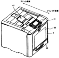
図1は、本実施形態に係る画像形成装置である、複数の像担持体である感光体が並行に配設されたタンデム型のカラーレーザープリンタ(以下、単に「プリンタ」という)の外観斜視図である。図2は、このプリンタの概略構成図である。 Figure 1 is an external perspective view of a tandem-type color laser printer (hereinafter simply referred to as a "printer"), which is an image forming apparatus according to this embodiment, in which multiple photoconductors, which are image carriers, are arranged in parallel. Figure 2 is a schematic diagram of this printer.
プリンタの下部には、複数枚の用紙Pを積層状態で収納する給紙トレイ30が配置されている。給紙トレイ30の上方でプリンタ本体の側面には、プリンタ内部の点検用の開閉カバー8が、開閉カバー8の下部を軸支する回転軸12を中心にプリンタ本体に対して開閉可能に設けられている。また、プリンタ本体の上部には、画像が形成された用紙Pがプリンタ内部から排紙される排紙トレイ45が設けられている。
A
また、プリンタの上部手前側には、ユーザーが各種情報を入力する入力手段としての操作表示部48が設けられている。
In addition, an
図2に示すようにプリンタ内部には、シアン(C)、マゼンタ(M)、イエロー(Y)、ブラック(K)の各色の画像を形成するための画像形成部(作像装置)として、4つのプロセスユニット1C,1M,1Y,1Kが配設されている。 As shown in FIG. 2, inside the printer, four process units 1C, 1M, 1Y, and 1K are arranged as image forming sections (imaging devices) for forming images of the colors cyan (C), magenta (M), yellow (Y), and black (K).
4つのプロセスユニット1C,M,Y,Kは、トナーの色が異なる点以外はいずれもほぼ同じ構成である。以下の説明では、便宜上、構成部材を示す番号の後ろに作像する画像のトナー色に対応させてC、M、Y、Kを添え字として付すことにする。なお、一般的な説明では、これらの添え字を適宜省略する。 The four process units 1C, M, Y, and K are all substantially the same in configuration, except that they use different toner colors. For convenience in the following explanation, the numbers indicating the components are followed by the letters C, M, Y, and K to correspond to the toner colors of the images to be produced. In general explanations, these letters will be omitted as appropriate.
各プロセスユニット1C,M,Y,Kはそれぞれドラム状の感光体2C,2M,2Y,2Kを備え、4個の感光体2C,M,Y,Kは、画像形成部内の図2中左右方向に等間隔で離間させて並列に配設されている。各感光体2C,M,Y,Kはプリンタの動作時に、駆動源から駆動が伝達されることにより、図2中時計方向に回転する。 Each process unit 1C, M, Y, K is equipped with a drum-shaped photoconductor 2C, 2M, 2Y, 2K, respectively, and the four photoconductors 2C, M, Y, K are arranged in parallel at equal intervals in the left-right direction in FIG. 2 within the image forming section. When the printer is in operation, each photoconductor 2C, M, Y, K rotates in the clockwise direction in FIG. 2 by receiving drive from the drive source.
各感光体2C,2M,2Y,2Kの周囲には、現像装置5C,M,Y,Kなど、電子写真方式の作像に必要な部材、装置が配備されている。
Around each photoconductor 2C, 2M, 2Y, 2K, there are components and devices necessary for electrophotographic image production, such as developing
感光体2C,M,Y,Kの上方には各色毎の画像データ対応のレーザ光Lを、各帯電ローラ4C,M,Y,Kで一様に帯電済みの各感光体2C,M,Y,Kの表面に走査し、静電潜像を形成するための潜像形成手段としての露光器7が設けられている。
Above the photoconductors 2C, M, Y, and K, an
各帯電ローラ4と各感光体2との間には、この露光器7により照射するレーザ光Lが感光体2に向けて入り込むように、細長いスペースが感光体2の回転軸の方向に確保されている。
A long and narrow space is provided between each
図1に示す露光器7は、レーザ光源、ポリゴンミラー等を用いたレーザスキャン方式の露光装置であり、4個の半導体レーザから、形成すべき画像データに応じて変調したレーザ光Lを発する。
The
露光器7は金属または樹脂製の筐体により、光学部品、制御用部品を収納し、下面の出射口には、透光性の防塵部材を備えている。
The
なお、図2に示す露光器7は1個の筐体で構成されているが、複数の露光装置を各作像部に個別に設けることもできる。また、レーザ光を採用する露光装置のほかに、公知のLEDアレイと結像手段とを組合せた露光装置も採用できる。
The
レーザ光Lにより各感光体2K,2Y,2M,2Cの表面に形成された色毎の静電潜像は、各色に対応した現像装置5C,M,Y,Kによりトナーで現像され顕像となる。
The electrostatic latent images for each color formed on the surface of each photoconductor 2K, 2Y, 2M, and 2C by the laser light L are developed with toner by the developing
感光体2C,M,Y,Kの下方には、転写装置15が配設されている。この転写装置15は、無端状のベルト部材である中間転写ベルト16を有しており、中間転写ベルト16従動ローラ17と駆動ローラ18とに巻き掛けられている。
A
そして駆動源によって駆動される駆動ローラ18が回転することによって、中間転写ベルト16が図2中矢印方向に回転し、各感光体2の表面が、中間転写ベルト16のおもて面に接触するようになっている。
Then, as the
中間転写ベルト16の内周部には、中間転写ベルト16を介して各感光体2に対向させた4つの一次転写ローラ19Y,C,M,Kが設けられている。
Four primary transfer rollers 19Y, C, M, and K are provided on the inner circumference of the
中間転写ベルト16の駆動ローラ18近傍の外周部には、中間転写ベルト16のおもて面をクリーニングするベルトクリーニング装置21が設けられている。このベルトクリーニング装置21は、中間転写ベルト16のおもて面に残留する不要なトナーや、紙粉などの異物を除去するためのものである。
A belt cleaning device 21 that cleans the front surface of the
中間転写ベルト16としては、例えば、厚さが50[μm]~600[μm]の樹脂フィルムまたはゴムを基体とするベルト部材を使用することができる。当該ベルト部材は、各感光体2が担持するトナー像を、各一次転写ローラ19にバイアスを印加することにより、ベルト表面に転写できるような抵抗値を有する。
The
一次転写ローラ19は、例えば芯金たる金属ローラの表面に導電性ゴム材料を被覆したもので、芯金に電源からバイアスが印加される。導電性ゴム材料は、例えばウレタンゴムにカーボンが分散されたもので、体積抵抗105[Ω・cm]程度に抵抗が調整されている。なお、一次転写ローラ19としては、ゴム層を有さない金属ローラも採用可能である。 The primary transfer roller 19 is, for example, a metal roller having a core covered with a conductive rubber material, and a bias is applied to the core from a power source. The conductive rubber material is, for example, urethane rubber with carbon dispersed therein, and the resistance is adjusted to about 105 Ω·cm volume resistance. Note that a metal roller without a rubber layer can also be used as the primary transfer roller 19.
中間転写ベルト16を挟んで駆動ローラ18と対向する位置には、二次転写ローラ20が設けられている。二次転写ローラ20は、例えば芯金たる金属ローラの表面に導電性ゴムを被覆したもので、芯金に電源からバイアスが印加される。導電性ゴムにはカーボンが分散されており、体積抵抗は107[Ω・cm]程度に抵抗が調整されている。
A
二次転写ローラ20は、駆動ローラ18と対向する位置で中間転写ベルト16に当接し、二次転写部としての二次転写ニップを形成している。二次転写ニップでは、中間転写ベルト16と二次転写ローラ20との間に用紙Pを通過させながらバイアスを印加することで、中間転写ベルト16のおもて面に担持されたトナー画像が、用紙Pに静電的に転写される。
The
中間転写ベルト16と給紙トレイ30との間には、廃トナーを収容する粉体収容器10が配設されている。この粉体収容器10には、ベルトクリーニング装置21により中間転写ベルト16から除去されたトナーなどが搬送路を搬送されて収納される。
Between the
本実施形態のプリンタでは、給紙トレイ30と二次転写ローラ20との間の上下方向の間隔を、その間にガイド55,56やレジストローラ対32を配設する関係で、ある程度大きく設定する必要がある。このため、中間転写ベルト16と給紙トレイ30との間にデッドスペースができるが、このデッドスペースに粉体収容器10を設置することで、当該デッドスペースを有効利用し、プリンタ全体の小型化を図っている。
In the printer of this embodiment, the vertical distance between the
給紙トレイ30の内部には、複数枚の用紙Pを積層状態で載せるための底板46が配設されている。この底板46は図2の左端が支軸によって回動自在に支持され、右端が上下方向に揺動可能とされている。また、底板46はバネの力で常時上方に付勢されている。
Inside the
給紙トレイ30の用紙搬送方向下流側の上部には、給紙ローラ47が配設されている。この給紙ローラ47は底板46上に載置された用紙Pの束の最上部に当接し、この最上部の用紙Pを、用紙搬送方向下流側の搬送路31に向けて繰り出すことができるようになっている。
A
なお、給紙ローラ47は用紙Pを搬送路31に向けて搬送する機能があればよく、必ずしもローラの形態である必要はない。例えば、給紙ローラ47に代えて、2つのローラ間に掛け渡した無端状の回転ベルトを使用してもよい。
The
搬送路31の用紙搬送方向下流側の末端付近には、用紙Pを一旦停止させるレジストローラ対32が配設されている。
A pair of
このレジストローラ対32は、二次転写ニップの用紙搬送方向上流側で近傍に位置しており、中間転写ベルト16上のトナー像と、用紙先端位置とを精度良く合わせるために、用紙Pを一旦停止させて当該用紙Pを一時的に弛ませる。そして、中間転写ベルト16上に形成されたトナー像が二次転写ニップに到達する直前に、一旦停止させていた用紙Pを所定のタイミングで二次転写ニップに送り出す。
The pair of
図1に示すように、操作部がプリンタ手前側に設けられた、フルフロントオペレーションタイプのプリンタでは、中間転写ベルト16のプリンタ手前側に、両面印刷時に用紙Pを反転させるための両面ユニット9を配置する場合が多い。
As shown in Figure 1, in full front operation type printers where the operation unit is located at the front of the printer, a duplex unit 9 for reversing the paper P during duplex printing is often located at the front of the
このため、二次転写ローラ20やレジストローラ対32のプリンタ手前側には、スペース的な余裕が少ない。そこで、本実施形態のプリンタでは、二次転写ローラ20やレジストローラ対32のニップを斜め方向に配置して省スペース化を図っている。
For this reason, there is little space available in front of the printer, near the
特に、二次転写ローラ20の圧縮バネ25は大型であるため、斜め方向に配置することで両面ユニット9のデッドスペースを有効利用し、プリンタの前後方向の省スペース化を図ることができる。
In particular, since the compression spring 25 of the
レジストローラ対32は、中間転写ベルト16の駆動ローラ18よりもプリンタ奥側に配設されている。このため、レジストローラ対32の転写カバー側ローラは、開閉カバー8に対して図2に示す位置のままでは開閉カバー8を開く際に、その回転軌跡A2が駆動ローラ18と干渉する。
The
すなわち、開閉カバー8の回転軸12を中心とする半径R2の回転軌跡A2が、駆動ローラ18と干渉する。この干渉を回避するため、レジストローラ対32の転写カバー側ローラは、開閉カバー8を開く途中で、退避機構により回転軌跡A2の半径方向内側に揺動するように構成されている。
That is, the rotation trajectory A2 of radius R2 centered on the
二次転写ニップの上方には、転写後搬送路33が配設されており、この転写後搬送路33の用紙搬送方向下流側の末端付近には定着装置34が設けられている。
A
定着装置34は、ハロゲンランプ等の発熱源を内包する定着ローラ34aと、この定着ローラ34aに対して所定の圧力で当接しながら回転する加圧ローラ34bとを備えている。なお、定着装置としては、無端状の回転ベルトを採用したものや、IH加熱方式など他の構成も可能である。
The fixing
定着装置34の上方には、定着後搬送路35が配設されており、この定着後搬送路35の途中で排紙路36と反転搬送路41とに分岐しており、この分岐点に揺動軸42aを中心に揺動する切替部材42が配設されている。
A
排紙路36の用紙搬送方向下流側の末端には、用紙Pをプリンタ内部から外に排出する排出手段としての排紙ローラ対37が配設されている。
At the downstream end of the
切替部材42を図2に示す実線の位置に位置させることで、定着装置34により定着が終了した用紙Pが定着後搬送路35から排紙路36に案内され、排紙ローラ対37により排紙トレイ45上に排紙しスタックさせる。
By positioning the switching
また、用紙Pのおもて面と裏面との両面に画像を形成する両面印刷においては、片面の定着を終了した用紙Pの後端が切替部材42を通過した後、切替部材42を図2に示す実線の位置から図中反時計まわり方向に回動させて破線の位置に位置させる。そして、排紙ローラ対37を逆回転させると、用紙Pが切替部材42にガイドされて反転搬送路41に案内され、搬送ローラ対43,44などにより再度、レジストローラ対32に送られる。
In double-sided printing, in which images are formed on both the front and back sides of paper P, after the rear end of paper P that has completed fixing on one side passes switching
次に、このプリンタの基本動作について説明する。まず、用紙Pの片面だけに画像を形成する片面印刷時の動作について説明する。 Next, we will explain the basic operation of this printer. First, we will explain the operation when printing on one side, where an image is formed on only one side of the paper P.
プリンタの制御部からの搬送信号により給紙トレイ30の給紙ローラ47が回転すると、給紙トレイ30の底板46上に積載された用紙Pの最上部の用紙Pのみが、その下側の用紙Pから分離されて搬送路31へ送り出される。
When the
そして、用紙Pの先端がレジストローラ対32のニップ部に到達すると、中間転写ベルト16上に形成されるトナー画像とタイミング(同期)をとり、かつ、用紙Pの先端スキューを補正するため、用紙Pに弛みを形成した状態で待機する。
When the leading edge of the paper P reaches the nip between the pair of
ここで、プリンタの作像動作をプロセスユニット1Kを例に挙げて説明する。まず、感光体2Kの表面が帯電ローラ4Kによって均一な高電位に帯電される(マイナス帯電)。この感光体2Kの表面に対して、画像データに基づいて露光器7からレーザ光Lが照射され、感光体表面のレーザ光Lが照射された部分の電位が低下することで、感光体2Kの表面に静電潜像が形成される。
Here, the printer's image forming operation will be explained using the process unit 1K as an example. First, the surface of the photoconductor 2K is charged to a uniform high potential by the charging roller 4K (negative charge). The surface of this photoconductor 2K is irradiated with laser light L from the
現像装置5の現像ローラの外周面に担持されたブラックトナーは、感光体2Kの表面の静電潜像に静電吸着され、当該静電潜像がトナーで現像されて可視像となる。この可視像が、感光体2Kと同期して回転する中間転写ベルト16の表面に対し、プラスに帯電された一次転写ローラ19による転写作用を受けて一次転写される。
The black toner carried on the outer peripheral surface of the developing roller of the developing device 5 is electrostatically attracted to the electrostatic latent image on the surface of the photoconductor 2K, and the electrostatic latent image is developed with toner to become a visible image. This visible image is primarily transferred to the surface of the
このような潜像形成、現像、一次転写の各動作は、すべてのプロセスユニット1C,M,Y,Kで画像データと対応してタイミングをとって順次行われる。 These latent image formation, development, and primary transfer operations are performed sequentially in all process units 1C, M, Y, and K in accordance with the image data.
この結果、中間転写ベルト16の表面上に、シアン(C)、マゼンタ(M)、イエロー(Y)及びブラック(K)の各色トナー画像が順次重なり合った4色トナー画像が担持される。そして、この4色トナー画像が、図2中矢印方向に回転する中間転写ベルト16と共に搬送される。
As a result, a four-color toner image is carried on the surface of the
ドラムクリーニング装置3Kは、感光体2Kから中間転写ベルト16にトナー画像を転写した後の感光体表面に付着している残留トナーを除去する。ドラムクリーニング装置3Kにより感光体2Kから除去された残留トナーは、廃トナー搬送手段によって、プロセスユニット1K内にある廃トナー収容部へ送られ回収される。また、除電装置は、ドラムクリーニング装置3Kによりクリーニングされた後の感光体表面は、除電装置により残留電荷が除電される。
The drum cleaning device 3K removes residual toner adhering to the surface of the photoconductor 2K after the toner image is transferred from the photoconductor 2K to the
以上のように各色トナー画像が中間転写ベルト16に転写されると、レジストローラ対32と給紙ローラ47とが駆動を開始し、中間転写ベルト16に転写されたトナー画像とタイミング(同期)をとって、用紙Pが二次転写ニップに送られる。
When each color toner image has been transferred to the
二次転写ローラ20はプラスに帯電されており、二次転写ニップへ送られてきた用紙Pに中間転写ベルト16上のトナー画像が静電的な力によって転写される。
The
中間転写ベルト16の表面の残留トナーや異物は、次の作像工程や転写工程のためにベルトクリーニング装置21によって除去される。中間転写ベルト16から除去されたトナーや異物は、廃トナー搬送手段によって搬送経路内を搬送され、粉体収容器10に送り込まれ粉体収容器10に収容される。
Residual toner and foreign matter on the surface of the
二次転写ニップでトナー画像が転写された用紙Pは、転写後搬送路33を通って定着装置34へと搬送される。定着装置34に送り込まれた用紙Pは、定着ローラ34aと加圧ローラ34bとの間に挟まれ、その未定着トナー画像が加熱及び加圧されて用紙Pに定着される。トナー画像が定着された用紙Pは、定着装置34から定着後搬送路35へ送り出される。
The paper P to which the toner image has been transferred at the secondary transfer nip is transported through
定着装置34から用紙Pを送り出したタイミングでは、切替部材42は図2に示す実線の位置にあり、定着後搬送路35の用紙搬送方向下流側の末端付近を開放している。用紙Pは、定着後搬送路35を通過した後、排紙ローラ対37に挟み込まれ、排紙トレイ45へ画像面が下向き(フェースダウン)で排出される。
When the paper P is sent out from the fixing
次に、プリンタで、用紙Pの両面に画像を形成する両面印刷時の動作について説明する。なお、用紙Pの片面に画像を定着させて、定着装置34から定着後搬送路35に用紙Pを送り出すまでの工程は、上述した片面印刷時と同様のため、その説明は省略する。
Next, we will explain the operation of the printer during double-sided printing, in which an image is formed on both sides of paper P. Note that the process of fixing the image on one side of paper P and sending paper P from fixing
両面印刷を行う場合は、片面にトナー画像が定着され排紙ローラ対37によって搬送される用紙Pの後端が、定着後搬送路35を通り抜けると、切替部材42が図2に示す点線の位置に揺動し、定着後搬送路35の用紙搬送方向下流側の末端付近が閉鎖される。これとほぼ同時に、排紙ローラ対37が逆回転し、用紙Pが逆送されて切替部材42にガイドされながら反転搬送路41へ進入する。
When double-sided printing is performed, when the rear end of the paper P, which has a toner image fixed on one side and is being transported by the pair of
反転搬送路41を搬送される用紙Pは、搬送ローラ対43,44などを経てレジストローラ対32に至り、中間転写ベルト16上に形成された裏面用のトナー画像とタイミングを合わせて送り出される。
The paper P transported along the reverse transport path 41 passes through transport roller pairs 43 and 44 and reaches
用紙Pの裏面に形成すべき画像は、用紙Pが所定のところまで搬送された時に開始される作像工程により順次形成される。この場合の作像工程もまた前述の片面印刷時のフルカラートナー画像形成と同様であり、このフルカラートナー画像を中間転写ベルト16上に担持させる。
The image to be formed on the back side of the paper P is formed sequentially by an image-making process that starts when the paper P is transported to a specified location. The image-making process in this case is also the same as the full-color toner image formation during single-sided printing described above, and this full-color toner image is carried on the
ただし、用紙Pは反転搬送路41で用紙搬送方向の前後が反転されているため、最初に作像されたときに対し、用紙搬送方向で逆から作像されるよう、露光器7からレーザ光Lを感光体表面に照射し静電潜像の作成が制御、実行される。
However, since the paper P is reversed in the paper transport direction in the reversing transport path 41, the laser light L from the
レジストローラ対32から送り出された用紙Pは、二次転写ニップを通過する際に、その裏面に中間転写ベルト16上のトナー画像が転写される。用紙Pの裏面のトナー画像が定着装置34によって定着された後、定着後搬送路35、排紙路36、排紙ローラ対37を順次経由して排紙トレイ45へ排出される。
When the paper P sent out from the
なお、プリントは両面印刷の効率を上げるために、搬送路31内で数枚の用紙Pを同時に搬送することができる。
In addition, to increase the efficiency of double-sided printing, several sheets of paper P can be transported simultaneously within the
また、図2に示すように装置本体の図中右側面には、手差しトレイ69が図中矢印方向に開閉可能に設けられており、この手差しトレイ69を開放することにより、そこから手差し給紙ができるようになっている。
As shown in FIG. 2, a
図3は手差しトレイ69から用紙を給紙する手差し給紙装置の断面図である。
手差し給紙装置には、シート載置部たる手差しトレイ69上に積載された用紙Pを給紙するための給送部材たる給紙ローラ61が設けられている。
FIG. 3 is a cross-sectional view of a manual paper feeder that feeds paper from a
The manual paper feed device is provided with a
また、積載された用紙Pを給紙ローラ61に圧接させる圧接位置と当該圧接位置から退避した退避位置との間で、手差しトレイ69の給紙方向上流側に設けられた回動軸を中心に回動可能な底板62が手差しトレイ69に設けられている。
The
手差しトレイ69と底板62との間には、底板62を給紙ローラ61に向かって付勢する付勢手段であるスプリング63が設けられており、底板62は、スプリング63によって給紙ローラ61に向かって付勢されている。
A
底板62よりも給紙方向下流側で給紙ローラ61の下面に接触し給紙される用紙Pを1枚ずつに分離する摩擦部材64が、用紙Pの搬送をガイドする搬送ガイド部材68に位置決めされた保持部材65の給紙方向上流側端部の上面に設けられている。
A
保持部材65の給紙方向上流側端部は、スプリング66からの押圧力によって給紙ローラ61に向かって付勢されており、保持部材65に設けられた摩擦部材64と給紙ローラ61とを圧接させている。これにより、給紙ローラ61と摩擦部材64との圧接部に底板62から用紙Pが送りこまれた際に、用紙Pに対して一定の摩擦力をかけることができる。
The upstream end of the holding
また、給紙ローラ61と摩擦部材64との圧接部に2枚の用紙Pが重なって送られた場合でも、前記摩擦力により用紙Pを1枚に分離して搬送することができる。1枚に分離された用紙Pは、搬送ガイド部材68によってガイドされながら搬送される。
Even if two sheets of paper P are fed overlappingly to the pressure contact area between the
また、手差しトレイ69は、開閉カバー8に対して回動軸を中心に回動可能に保持されている。そして、手差し給紙使用時には開閉カバー8に対して手差しトレイ69を開放した開放状態とし、手差し給紙を使用しない場合は、開閉カバー8に手差しトレイ69を収納することが可能である。なお、開閉カバー8に手差しトレイ69を収納した場合、手差しトレイ69に軸支されている底板62も開閉カバー8に収納される。
The
図4は手差し給紙終了後における手差し給紙装置の断面図である。
給紙ローラ61による底板62からの用紙給紙動作を実施している間は、給紙ローラ61によって用紙Pに搬送力を付与必要がある。そのため、図3に示すように、底板62を圧接位置に位置させ、底板62上の用紙Pを給紙ローラ61に圧接させておく。一方、用紙給紙動作が終了した後は、ユーザーが用紙Pを手差しトレイ69に補給することを考慮して、図4に示すように底板62を圧接位置から退避位置に底板62を退避させ、底板62上の用紙Pと給紙ローラ61との圧接を解除する。
FIG. 4 is a cross-sectional view of the manual paper feeder after manual paper feed is completed.
During the
なお、前述したように底板62にはスプリング63により常に給紙ローラ61に向かって付勢され加圧力がかかっているので、給紙ローラ61の回転軸である給紙ローラ軸70に回転可能に支持されたカム71を回転動作させ、底板62にカム71を当接させる。これにより、スプリング63からの付勢に抗して底板62がカム71によって押し下げられ、底板62を給紙ローラ61から退避させることができる。
As described above, the
また、図3に示すように用紙給紙時では、底板62が圧接位置から退避して給紙ローラ61により用紙Pに与える搬送力を損なわれないようにするため、カム71と底板62とが接触しない姿勢でカム71を停止させておく。
As shown in FIG. 3, when feeding paper, the
すなわち、カム71は、底板62に接触せず底板62を圧接位置に位置させる上昇位置と、底板62が圧接位置から退避し底板62上に用紙Pの補給が可能となる下降位置との、2種類の位置で停止させる構成となっている。
In other words, the
なお、図4の紙面奥行き方向において、シート搬送装置としての手差し給紙装置で対応しうる最大の用紙幅よりも外側で、底板62にカム71を接触させており、底板62上に積載された用紙Pとカム71とが接触しないようにしている。
In addition, in the depth direction of the paper surface of FIG. 4, the
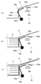
図5は手差し給紙装置の斜視図であり、図6は、手差し給紙装置の平面図である。手差しトレイ69には、手差しトレイ69にセットされた用紙を挟むようにして用紙を幅方向に規制する一対のサイドフェンス69aが設けられている一対のサイドフェンス69aは、用紙幅方向に手動で移動可能であり、用紙の幅方向のサイズに合わせて位置決めされる。
Figure 5 is a perspective view of the manual paper feed device, and Figure 6 is a plan view of the manual paper feed device. The
給紙ローラ61は給紙ローラ軸70に対してDカットまたはピンなどで回転止めされている。給紙ローラ軸70には、給紙ローラ軸70への駆動の伝達や遮断を切り替え可能な電磁クラッチを介して駆動源である駆動モータ85から駆動力が供給される。
The
給紙ローラ軸70には、カム71が回転止めのない状態で設けられており、給紙ローラ61の回転と同期せずにカム71が独立して回転可能となっている。カム71にはギヤ73がカップリング連結または一体成型されており、駆動モータ85からの駆動力が電磁クラッチを介してギヤ73に伝達されることで、カム71が回動する。
A
レジストローラ対32の手前には、レジストセンサ32aが設けられている。レジストセンサ32aが用紙の先端検知をトリガとして、レジストローラよりも上流側の搬送ローラを規定時間回転させて、用紙に所定量の撓みを作ってスキュー補正したら、レジストローラよりも上流側の搬送ローラの回転を停止し給紙動作が完了する。
A
また、手差しトレイ69への用紙のセットを検知するセット検知部84を有している。セット検知部84は、回転自在に支持された揺動部材としてのセットフィラー84aと、セットフィラー84aの被検知部184bを検知する光学センサ84bとを有している(図14参照)。
セットフィラー84aは、用紙幅方向において、給紙ローラ61の近傍に設けられており、セットされた用紙の先端が突き当たる壁部68aから突出している。
The
The
手差しトレイ69に用紙がセットされると、用紙の先端が、セットフィラー84aを押し込み、セットフィラー84aを回動させる。セットフィラー84aが回動すると、被検知部184bが光学センサ84bにより検知される検知位置から退避位置へ移動する(図14(a)、図14(b)参照)。これにより、光学センサ84bの信号が変化し、用紙がセットされたことが検知される。
When paper is set in the
本実施形態では、手差しトレイ69にセットされた用紙を用いて印刷を行うときに、セット検知部84が用紙のセットを検知しているか否かを確認し、セット検知部84が用紙のセットを検知していないときは、操作表示部48に手差しトレイ69に用紙がセットされていない旨の表示を行う。
In this embodiment, when printing is performed using paper set in the
また、手差しトレイ69には、手差しトレイ69にセットされる用紙の幅を検知する幅検知部90を有している。幅検知部90は、セット検知部84と同様、回転自在に支持された揺動部材としての幅検知フィラー91と、幅検知フィラー91の被検知部91bを検知する光学センサ92とを有している(図9参照)。
幅検知フィラー91は、用紙幅方向において、給紙ローラ61から離れて設けられており、図7に示すように、セットされた用紙の先端が突き当たる壁部68aから突出している。
The
The
規定幅以上の用紙が手差しトレイ69にセットされると、用紙の先端が、幅検知フィラー91を押し込み、幅検知フィラー91を回動させる。幅検知フィラー91が回動すると、被検知部91bが退避位置から光学センサ92に検知される検知位置へ移動する(図9(a)、図9(b)参照)。これにより、光学センサ92の信号が変化し、規定幅以上の用紙がセットされたことが検知される。
When paper of a specified width or greater is set in the
本実施形態では、規定幅以上の用紙(以下、大サイズ用紙という)に画像を形成するときと、規定幅未満の用紙(以下、小サイズ用紙という)に画像を形成するときとで紙間を変更している。これは、規定幅未満の小サイズ用紙に対して連続印刷を行う場合、定着ローラ34aや加圧ローラ34bの軸方向両側は、紙に熱が奪わることがないため、定着ローラ34aや加圧ローラ34bの軸方向両側が異常高温となるおそれがある。そのため、本実施形態では、小サイズ用紙に画像を形成するときは、大サイズ用紙に画像を形成するときに比べて、紙間を広げる制御を行う。紙間を広げることで、定着ローラ34aが加熱されない期間を延ばすことができる。この定着ローラ34aが加熱されない期間が長くなることで、定着ローラ34aや加圧ローラ34bの軸方向両側の熱が自然放熱される期間が長くなり、定着ローラ34aや加圧ローラ34bの軸方向両側の温度上昇を抑制することができる。その結果、小サイズ用紙に対して連続印刷を行うときの定着ローラ34aや加圧ローラ34bの軸方向両側が異常高温となるのを抑制している。
In this embodiment, the paper interval is changed when forming an image on paper of a specified width or more (hereinafter referred to as large size paper) and when forming an image on paper of less than the specified width (hereinafter referred to as small size paper). This is because, when performing continuous printing on small size paper of less than the specified width, both sides of the axial direction of the fixing
プリンタの制御部300(図16参照)は、ユーザーが操作表示部48を操作して入力した用紙の幅サイズ情報に基づいて、紙間を広げる制御を行うか否かを判定している。そのため、ユーザーが操作表示部48を操作して入力した用紙サイズが規定幅以上の大サイズ用紙にもかかわらず、実際、手差しトレイ69にセットされた用紙は、小サイズ用紙である場合は、定着ローラ34aや加圧ローラ34bの軸方向両側が異常高温となるおそれがある。
The printer's control unit 300 (see FIG. 16) determines whether to control the paper spacing to be increased based on the paper width size information input by the user through the
よって、本実施形態では、この幅検知部90の結果が入力した用紙幅サイズに合致していないときは、操作表示部48に入力した用紙幅サイズに合致していないがある旨を表示して、手差しトレイ69に入力した用紙幅サイズに合致した用紙をセットするように促す表示を行っている。
Therefore, in this embodiment, when the result of this
手差しトレイ69の一対のサイドフェンス69aは、用紙幅方向に手動で移動させて、手差しトレイ69にセットされた用紙を幅方向で規制するようなものである。そのため、ユーザーによっては、このサイドフェンス69aの移動を忘れてしまうことがあり、用紙がスキューした状態で手差しトレイ69にセットされることがある。その結果、手差しトレイ69にセットした用紙サイズと、入力した用紙サイズとが合致しているにも関わらず、用紙サイズが合致していないと誤判定したり、手差しトレイ69にセットした用紙サイズと、入力した用紙サイズとが合致していないにも関わらず、用紙サイズが合致していると誤判定したりするおそれがあった。
The pair of
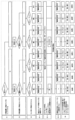
図8は、従来における用紙サイズ判定フローを示す図である。
図8の結果2のフローが示すように、入力した用紙サイズが大サイズ(S1の大)で、手差しトレイ69にセットしたサイズも大サイズ(S2の大)であっても、一対のサイドフェンス69aを用紙の幅方向両端に当てて用紙揃えを行わずにスキューした状態である場合(S3の有り)は、用紙の先端が幅検知フィラー91を押し込まず、幅検知部90の検知結果が、小サイズ用紙がセットされたと誤判定してしまう(S4の幅検知判定:小)。その結果、入力した用紙サイズが大サイズで、手差しトレイ69にセットしたサイズも大サイズであっても、入力した用紙サイズとセットされた用紙サイズとが異なるサイズミス判定(S5のサイズミス)をし、操作表示部48には、入力した用紙幅サイズに合致していない旨を表示してしまう。
FIG. 8 is a diagram showing a conventional paper size determination flow.
As shown in the flow of result 2 in Fig. 8, even if the input paper size is large (S1 large) and the size set in the
また、図8の結果6が示すように、入力した用紙サイズが小サイズ(S1の小)で、手差しトレイ69にセットしたサイズが大サイズであった場合(S2の大)に、一対のサイドフェンス69aを用紙の幅方向両端に当てる用紙揃えが行わずスキューした状態で大サイズ用紙がセットされてしまう(S3の有り)ことで、幅検知部90は、小サイズ用紙がセットされていると誤判定してしまう(S4の幅検知判定:小)。その結果、手差しトレイにセットされた用紙サイズと入力した用紙サイズが小サイズとが同一であると誤判定してしまう(S5の同一)。
Also, as shown in result 6 in FIG. 8, if the input paper size is small (S1 small) and the size set in the
このため、給紙ローラ61からレジストローラ対32までの間の手差し給紙路に、用紙幅方向において幅検知部90と同一の位置に第二の幅検知部を設け、この第二の幅検知部で、大サイズ用紙スキューセットなのか、小サイズ用紙セットなのかを検知することも考えられる。大サイズ用紙スキューセットのときは、第二の幅検知部が搬送されてくる用紙を検知するので、大サイズ用紙スキューセットと判定できる。一方、所定のタイミングとなっても第二の幅検知部が用紙を検知しないときは、小サイズ用紙と判定できる。
しかしながら、幅検知部90とは別に、第二の幅検知部を設けるため、部品点数の増加による装置のコストアップにつながるおそれがある。
For this reason, it is conceivable to provide a second width detection unit at the same position in the paper width direction as the
However, since a second width detection unit is provided in addition to the
そこで、本実施形態では、このような誤判定の発生を防止するために、幅検知部90で、大サイズ用紙スキューセットなのか、小サイズ用紙セットなのかを判別できるようにした。
Therefore, in this embodiment, in order to prevent such erroneous judgments from occurring, the
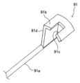
図9は、本実施形態の幅検知部90を示す断面模式図であり、図10は、本実施形態の幅検知部90の幅検知フィラー91を示す図であり、図11は、大サイズ用紙スキューセットおよび小サイズセットのときの幅検知部90を示す平面模式図である。
図9(a)は、大サイズ用紙スキューセットおよび小サイズセット時の断面模式図であり、図9(b)は、大サイズ用紙正常セット時(一対のサイドフェンスにより用紙揃えを行ってセットしたとき)の断面模式図である。また、図9(c)は、大サイズ用紙正常セット時の大サイズ用紙の搬送の様子を示す図である。
Figure 9 is a schematic cross-sectional view showing the
Fig. 9A is a schematic cross-sectional view of a large size sheet when skew-set and a small size sheet when set, Fig. 9B is a schematic cross-sectional view of a large size sheet when set normally (when the sheet is aligned by a pair of side fences), and Fig. 9C is a diagram showing the state of transport of the large size sheet when set normally.
本実施形態の幅検知部90においては、光学センサ92は反射型光学センサであり、発光部が発した光が、シート搬送路である手差し給紙路Rに照射されるように配置している。これにより、手差し給紙路Rの用紙から反射した光学センサ92の発光部の光を、光学センサ92の受光部が受光して手差し給紙路Rの用紙の有無を検知することができる。
In the
幅検知フィラー91は、図10に示すように、手差し給紙装置に回動自在に支持される回動軸91aと、回動軸91aの一端から軸方向に対して直交する方向に延びる手差しトレイ69にセットされた大サイズ用紙の先端が突き当たる用紙突き当て面91dとを有している。この用紙突き当て面91dの先端には、用紙搬送方向に延び出した被検知部91bが設けられており、この被検知部91bには、光学センサ92から照射された光を通過させるため切り欠き91cが設けられている。
As shown in FIG. 10, the
幅検知フィラー91は、トーションスプリングなどの付勢手段によって、図9中の反時計回りに回動する方向に付勢されており、初期状態では、切り欠き91cが光学センサ92の検知領域に位置し、幅検知フィラー91は、被検知部91bが検知領域から退避している。
The
手差しトレイ69に小サイズ用紙がセットされているとき、および、大サイズ用紙スキューセットのときは、図9(a)や、図11に示すように、用紙先端により用紙突き当て面91dが押し込まれることがない。そのため、幅検知フィラー91は、初期の姿勢であり、光学センサ92から照射された光は、切り欠き91cを通過して手差し給紙路Rへ照射される。従って、図11からわかるように、給紙動作を行って用紙を給紙したとき、大サイズ用紙がスキューセットされている場合は、光学センサ92から照射された光が用紙に反射し、光学センサ92の受光部が光を受光する。これにより、大サイズ用紙スキューセットであると判定できる。
When small size paper is set in the
図11からわかるように、小サイズ用紙の幅方向端部は、光学センサ92よりも幅方向中央側にある。よって、給紙動作を行って小サイズ用紙を給紙しても、光学センサ92は、用紙を検知することがない。よって、規定のタイミングとなっても、光学センサ92が用紙を検知しないときは、手差しトレイ69にセットされた用紙が、小サイズ用紙と判定することができる。
As can be seen from FIG. 11, the widthwise edge of small size paper is closer to the center in the widthwise direction than the
一方、図9(b)に示すように、一対のサイドフェンス69aにより用紙揃えが行われスキューが補正されて、大サイズ用紙が正しくセットされたときは、用紙の先端が、用紙突き当て面91dを押し込み、幅検知フィラー91が図中時計回りに回動する。よって、被検知部91bが光学センサ92の検知領域へ移動し、幅検知フィラー91は、光学センサ92が被検知部91bを検知する。これにより、光学センサ92が被検知部91bを検知して、大サイズ用紙が正しく手差しトレイ69にセットされたことを検知することができる。
On the other hand, as shown in FIG. 9(b), when the pair of
図9(c)に示すように、大サイズ用紙が正しくセットされたときは、被検知部91bが光学センサ92の光を遮ることになる。よって、このときは、給紙動作を行って用紙を給紙しても、光学センサ92の信号が変化せず、用紙の有無は検知できない。しかし、このときは、既に大サイズ用紙がセットされていることが確定しており、光学センサ92で手差し給紙路Rの用紙を検知したか否かで、大サイズスキューセットなのか否かの判別を行う必要がない。よって、光学センサ92が手差し給紙路Rの用紙の有無を検知できないようになっていても、なんら問題はない。
As shown in FIG. 9(c), when large size paper is set correctly, the detected
このように、本実施形態では、部品点数を増やすことなく、小サイズ用紙セット、大サイズ用紙スキューセット、大サイズ用紙正常セットを判別することができる。これにより、装置のコストアップを避けることができる。 In this way, in this embodiment, it is possible to distinguish between small size paper set, large size paper skew set, and large size paper normal set without increasing the number of parts. This makes it possible to avoid an increase in the cost of the device.
図12は、本実施形態における用紙サイズ判定フローを示す図である。
本実施形態では、図12のS4-1に示す光学センサ92が幅検知フィラー91の被検知部91bを検知して幅検知部90が大サイズ用紙のセットを検知したとき(S4-1の幅検知判定:大)は、入力した用紙サイズとセットされた用紙サイズとが異なるか否かの判定を行う(S5-1)。
FIG. 12 is a diagram showing a paper size determination flow in this embodiment.
In this embodiment, when the
一方、光学センサ92による幅検知フィラー91の被検知部91bを検知しておらず幅検知部90が小サイズ用紙のセットを検知したとき(S4-1の幅検知判定:小)は、用紙給紙を行って、S4-2に示す光学センサ92による用紙検知に基づく大サイズ/小サイズ判定を行う。そして、光学センサ92の用紙検知に基づく大サイズ/小サイズ判定結果が、入力した用紙サイズと一致しているか否かの判定を行う。これにより、結果2で示すように、入力サイズが大サイズ(S1の大)で、大サイズ用紙スキューセット(S2の大、S3のスキュー有り)の場合において、入力サイズとセットした用紙サイズとが同一と狙い通り判定することができる。また、結果6で示すように、入力サイズが小サイズ(S1の小)で、大サイズ用紙スキューセット(S2の大、S3のスキュー有り)の場合において、セットした用紙サイズが入力した用紙サイズと異なるサイズミスと狙い通り判定することができる。
On the other hand, when the
入力サイズが大サイズ用紙で、セットされた用紙が小サイズ用紙であると判定されたとき(図12の結果3、結果4)は、そのまま印刷を続けると、定着ローラ34aや加圧ローラ34bの軸方向端側が高温となるおそれがある。従って、このときは、画像形成動作を中止して、操作表示部48に入力した用紙幅サイズに合致していないがある旨を表示して、手差しトレイ69に入力した用紙幅サイズに合致した用紙をセットするように促す表示を行う。
When the input size is large size paper and the loaded paper is determined to be small size paper (
一方、入力サイズが小サイズ用紙で、セットされた用紙が大サイズ用紙であると判定されたとき(図12の結果5、結果6)は、用紙からはみ出して画像が形成されることもなく、また、定着ローラ34aや加圧ローラ34bの端側が高温となることもない。よって、そのまま印刷を行い、印刷後に操作表示部48に入力した用紙幅サイズに合致していないがある旨を表示する。もちろん、結果3、結果4と同様に、画像形成動作を中止して、操作表示部48に入力した用紙幅サイズに合致していないがある旨を表示して、手差しトレイ69に入力した用紙幅サイズに合致した用紙をセットするように促す表示を行うようにしてもよい。
On the other hand, when the input size is small size paper and the loaded paper is determined to be large size paper (Results 5 and 6 in FIG. 12), the image will not extend beyond the paper, and the ends of the fixing
また、例えば、光学センサ92が幅検知フィラー91の被検知部91bを検知し、大サイズ判定で、入力サイズと同一であったとき(図12の結果1のとき)は、直ちに画像形成動作を開始する。一方、光学センサ92が幅検知フィラー91の被検知部91bを検知せず小サイズ判定のときは、光学センサ92の用紙検知による大サイズ/小サイズ判定の結果、入力サイズと同一と判定されたら(図12の結果2、結果7、結果8)画像形成動作を開始するようにしてもよい。
Also, for example, when the
また、図12の結果3、結果4のとき(入力サイズ:大、セットサイズ:小)は、小サイズ用紙に画像が収まるように形成する画像を縮小して画像形成を行うようにするとともに、紙間の設定を小サイズ対応の紙間に設定変更して、画像形成動作を継続するようにしてもよい。また、図12の結果5、結果6のとき(入力サイズ:小、セットサイズ:大)は、画像を拡大して画像形成を行うようにするとともに、紙間の設定を大サイズ対応の紙間に設定変更して、画像形成動作を継続するようにしてもよい。
In addition, in the case of
また、光学センサ92の検知結果に基づいて大サイズ用紙のスキュー量を計測し、この計測したスキュー量に基づいて、スキュー補正を行うようにしてもよい。
In addition, the amount of skew of large-size paper may be measured based on the detection results of the
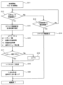
図13は、大サイズスキュー補正のフローチャートである。
駆動モータ85をONにし、給紙ローラ61の回転が開始され給紙が開始されると、タイマーがONとなり、時刻T[s]の計測が開始される(S11)。次に、プリンタの制御部300(図16参照)は、規定時間内に光学センサ92が用紙を検知するか否かを監視する(S12~S13)。規定時間内に光学センサ92が用紙を検知しないとき(S12のNo、S13のYes)は、セットされた用紙サイズを小サイズ用紙と判定する(S14)。一方、規定時間内に光学センサが用紙を検知したとき(S12のYes)は、セットされた用紙サイズを大サイズ用紙と判定するとともに、タイマーをストップして、計測時間T[s]を確定する(S15)。
FIG. 13 is a flowchart of large size skew correction.
When the
次に、プリンタの制御部300は、スキュー量ΔTを演算する(S16)。大サイズ用紙の先端がスキューしていない状態で、光学センサ92に到達するまでの理想到達時間をT0、通常時におけるレジストローラ対32に用紙の先端を突き当てて所定量撓ませて補正できるスキュー量をαとすると、スキュー量ΔTは、ΔT=T-T0-αの式で算出することができる。そして、ΔTが0を超えるときは、追加のスキュー補正を行うように設定(S17のYes)する。レジストセンサ32aが用紙の先端を検知して、用紙の先端がレジストローラ対32に到達したことを検知したら(S19)、α+ΔT時間、レジストローラよりも上流の搬送ローラを回転駆動し、スキュー補正を行う(S20)。
Next, the printer's
一方、ΔTが0以下のときは、追加のスキュー補正を行わない設定とし(S17のNo)、ΔT=0とする(S18)。そして、レジストセンサ32aが用紙の先端を検知し、用紙の先端がレジストローラ対32に到達したことを検知したら(S19)、通常のスキュー補正を行う(S20)。
On the other hand, if ΔT is equal to or less than 0, no additional skew correction is performed (No in S17), and ΔT is set to 0 (S18). Then, when the
これにより、大サイズ用紙が手差しトレイ69にスキューセットされた状態であっても、給紙動作でスキュー補正が良好に行われる。これにより、大サイズ用紙に形成される画像が、用紙に対して傾斜して形成されるのを抑制することができる。
As a result, even if large-size paper is skewed and set in the
また、計測時間T[s]は用紙のスタート位置やスリップ率、搬送速度によっても変わってくる。よって、用紙種や環境など使用条件に関する補正量を加味してΔTを演算することが好ましい。例えば、部品ばらつき、経時使用による摩耗により給紙ローラ61の径が変動することで、搬送速度が変わってくる。また、用紙種、用紙厚、用紙剛直度および給紙ローラ61の表面の汚れによりスリップ率が変化する。
The measurement time T [s] also varies depending on the starting position of the paper, the slip ratio, and the transport speed. Therefore, it is preferable to calculate ΔT taking into account correction amounts related to the usage conditions, such as the paper type and the environment. For example, the transport speed changes when the diameter of the
また、先行紙による次紙先端の連れ出され位置などにより用紙スタート位置が変化し、手差しトレイ上の用紙の先端から光学センサの検知位置までの距離の変化で、計測時間T[s]が変化する。また、光学センサ92の検知位置ばらつき各部品の位置ばらつきによっても、距離が変化する。電磁クラッチの連結のばらつきによる給紙ローラ61の回転開始タイミング(給紙開始のタイミング)がばらつくことで、計測時間T[s]がばらつくおそれもある。
The paper start position also changes depending on the position where the leading edge of the next paper is taken out by the preceding paper, and the measured time T [s] changes due to the change in the distance from the leading edge of the paper on the manual feed tray to the detection position of the optical sensor. The distance also changes due to variations in the detection position of the
このようなばらつきにより、スキュー補正をすることで、かえって用紙に対する画像スキューが悪化するおそれがある。よって、大サイズスキュー補正を行うか否かをユーザーが設定できるようにしてもよい。この場合、操作表示部48をユーザーが操作することで、大サイズスキュー補正を行うか否かの設定が行えるようにする。また、プリンタドライバーアプリケーションソフトがインストールされたパソコンからも大サイズスキュー補正を行うか否かの設定が行えるようにしてもよい。
Due to such variations, performing skew correction may actually worsen the image skew relative to the paper. Therefore, it may be possible to allow the user to set whether or not to perform large size skew correction. In this case, the user can operate the
また、理想到達時間T0を補正する理想到達時間補正モードを設けておき、例えば、工場出荷前や、サービスマンによる客先でのセッティング時に理想到達時間補正モードを実行して、理想到達時間T0を補正するようにしてもよい。これにより、部品の位置ばらつきなどの装置個々の特性による計測時間T[s]のばらつきが原因のΔTの算出精度の低下が抑えられる。 In addition, an ideal arrival time correction mode for correcting the ideal arrival time T0 may be provided, and the ideal arrival time correction mode may be executed, for example, before shipment from the factory or when a service technician sets up the device at the customer's site, to correct the ideal arrival time T0. This prevents a decrease in the calculation accuracy of ΔT caused by variations in the measurement time T [s] due to individual device characteristics such as variations in the position of parts.
また、装置の定期点検のときに、サービスマンにより理想到達時間補正モードを実行して、理想到達時間T0を補正することで経時使用による摩耗により給紙ローラ61の径が変化や、給紙ローラ61の表面の汚れなどによる経時使用による特性変化によるΔTの算出精度の低下が抑えられる。
In addition, during regular inspections of the device, a service technician can run the ideal arrival time correction mode to correct the ideal arrival time T0, thereby preventing a decrease in the accuracy of ΔT calculations due to changes in the diameter of the
また、用紙の種類、厚みおよび用紙剛直度に対応した複数の補正値を記憶しておき、ユーザーが操作表示部に入力した用紙の種類、厚みおよび用紙剛直度に基づいて、補正値を読み出し、計測時間T[s]を補正してもよい。これにより、用紙種、用紙厚および用紙剛直度による計測時間T[s]のばらつきが原因のΔTの算出精度の低下が抑えられる。 In addition, multiple correction values corresponding to the paper type, thickness, and paper stiffness may be stored, and the correction values may be read out and the measurement time T [s] may be corrected based on the paper type, thickness, and paper stiffness input by the user to the operation display unit. This prevents a decrease in the calculation accuracy of ΔT caused by variations in the measurement time T [s] due to paper type, paper thickness, and paper stiffness.
上記理想到達時間補正モードを行うときは、事前準備として、例えば、幅検知フィラー91を用紙幅方向にずらすなどして、大サイズ用紙が正しくセットされたときに、被検知部91bが光学センサ92の光を遮らないようにする。また、専用の治具を手差しトレイにセットして、大サイズ用紙が正しくセットされたときに、幅検知フィラー91が用紙に押し込まれないようにして、被検知部91bが光学センサ92の光を遮らないようしてもよい。
When performing the ideal arrival time correction mode, as a preliminary step, for example, the
次に、手差しトレイ69に大サイズ用紙をセットしたら、操作表示部48を操作して理想到達時間補正モードを実行し、給紙開始から光学センサ92が用紙を検知するまでの時間を計測する。そして、計測した時間を、補正後の理想到達時間T0として、メモリに記憶する。この時間計測を複数回行って、その平均値を補正後の理想到達時間T0としてメモリに記憶してもよい。
Next, after placing large size paper in the
また、用紙幅方向中央を挟んで光学センサ92の配置位置とは反対側にも光学センサを配置して、これら二つの光学センサを用いてスキュー量ΔTを算出するようにしてもよい。かかる構成においては、2つの光学センサのうち、一方の光学センサが用紙を検知してから他方の光学センサが用紙を検知するまでの時間から、スキュー量ΔTを求めることができる。かかる構成においては、上述の給紙ローラ61の回転開始タイミング(給紙開始のタイミング)のばらつきや、先行紙による次紙先端の連れ出され位置などにより用紙スタート位置のばらつきによる影響が無視でき、スキュー量ΔTの検知精度を高めることができる。
Also, an optical sensor may be placed on the opposite side of the paper width center from the position of
また、セット検知部84の光学センサを、手差し給紙路Rの用紙の有無を検知できるようにし、このセット検知部84で用紙のセット検知と用紙のスキュー検知とを行えるようにしてもよい。
The optical sensor of the
図14は、セット検知部84の断面模式図である。
図14(a)は、用紙セット前の断面模式図であり、図14(b)は、用紙セット後の断面模式図であり、図14(c)は、用紙搬送時の断面模式図である。
FIG. 14 is a schematic cross-sectional view of the
14A is a schematic cross-sectional view before paper is set, FIG. 14B is a schematic cross-sectional view after paper is set, and FIG. 14C is a schematic cross-sectional view during paper transport.
図14に示すように、セット検知部84は、セットフィラー84aと反射型の光学センサ84bとを有している。光学センサ84bは、幅検知部90の光学センサ92と同様、発光部が発した光が、手差し給紙路Rに照射されるように配置している。また、セット検知部84の光学センサ84bは、小サイズ用紙のスキューも検知できるよう、幅検知部90の光学センサ92よりも用紙幅方向において中央側に配置する。また、セット検知部84の光学センサ84bは、レジストセンサ32aよりも用紙搬送方向上流側に配置している。
As shown in FIG. 14, the
セットフィラー84aは、幅検知フィラー91と同様、手差し給紙装置に回動自在に支持される回動軸184aと、回動軸184aの一端から軸方向に対して直交する方向に延びる手差しトレイ69にセットされた用紙の先端が突き当たる用紙突き当て面184dとを有している。この用紙突き当て面184dの先端には、用紙搬送方向に延び出した被検知部184bが設けられており、この被検知部184bには、光学センサ84bから照射された光を通過させるため切り欠き184cが設けられている。
The
セットフィラー84aも幅検知フィラーと同様、トーションスプリングなどの付勢手段によって、図14中の反時計回りに回動する方向に付勢されており、用紙突き当て面184dの一部が、セットされた用紙の先端が突き当たる壁部68aから突出している。
Like the width detection filler, the
セットフィラー84aは、幅検知フィラー91とは異なり、初期状態のとき被検知部184bが光学センサ84bの検知領域に位置している。
The
用紙が、手差しトレイ69にセットされると、図14(b)に示すように、用紙の先端がセットフィラー84aを押し込み、セットフィラー84aが図中時計回りに回動し、被検知部184bが光学センサ84bの検知領域から退避し、セットフィラー84aは、切り欠き184cが検知領域に位置する。これにより、光学センサ84bは、被検知部184bを検知しなくなり、用紙が手差しトレイ69にセットされたことを検知することができる。
When paper is set in the
また、図14(b)に示すように、用紙が手差しトレイ69にセットされることで、被検知部184bが光学センサ84bの検知領域から退避し、光学センサ84bの発光部が発した光が、手差し給紙路Rに照射されるようになる。よって、図14(c)に示すように、給紙ローラ61により手差し給紙路Rへ搬送されてきた用紙に光学センサ84bの光が照射され、その用紙から反射した光を、光学センサ84bの受光部で受光して手差し給紙路Rの用紙の有無を検知することができる。
As shown in FIG. 14(b), when paper is set in the
図15は、セット検知部84の光学センサ84bでスキュー量を検知して、スキュー補正を行うフローチャートである。
駆動モータ85をONにして給紙ローラ61の回転し給紙が開始されると、時刻T[s]の計測が行われる。次に、プリンタの制御部300(図16参照)は、規定時間内に光学センサ84bが用紙を検知するか否かを監視する(S22~S23)。規定時間内に光学センサ84bが用紙を検知しないとき(S22のNo、S23のYes)は、未達ジャムが発生していると判定し(S24)、給紙動作を終了する。
FIG. 15 is a flow chart showing a process of detecting the amount of skew by the
When the
このように、レジストセンサ32aよりも用紙搬送方向上流側に配置されたセット検知部84の光学センサ84bにより、未達ジャム判定を行うので、レジストセンサ32aを用いて未達ジャム判定を行う場合に比べて、早い段階で未達ジャムを検知することができる。これにより、用紙の先端が未だ手差しトレイ69付近にある段階で未達ジャムを検知でき、ジャム処理を簡便にすることができる。
In this way, the
一方、規定時間内に光学センサ84bが用紙を検知したとき(S22のYes)は、先の図13を用いて説明した幅検知部90の光学センサ92を用いたスキュー補正と同様にして、追加スキュー量ΔTを算出し、算出した追加スキュー量ΔTに基づいて、追加のスキュー補正を行う(S26~S30)。
On the other hand, if the
このように、セット検知部84の光学センサ84bで用紙のスキュー検知および未達ジャム検知を行うことができる。よって、セット検知部84とは別に手差し給紙路Rに用紙検知部を設け、その用紙検知部の検知結果に基づいて用紙のスキュー検知および未達ジャム検知を行うものに比べて部品点数の削減を図れ、装置のコストダウンを図ることができる。
In this way, the
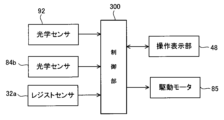
図16は、手差し給紙動作における制御ブロック図である。
図16に示すようにプリンタの制御部300には、操作表示部48、給紙ローラ61を駆動する駆動モータ85、幅検知部90の光学センサ92、セット検知部84の光学センサ84b、レジストセンサ32aなどが接続されている。
FIG. 16 is a control block diagram in the manual paper feed operation.
As shown in FIG. 16, the
制御部300は、幅検知部90の光学センサ92の被検知部91bの検知結果および手差し給紙路Rの用紙検知結果に基づいて、手差しトレイ69にセットされた用紙が、規定幅以上の用紙か否かを判別する判別手段として機能する。
The
また、制御部300は、ユーザーが操作表示部48を操作して入力した用紙のサイズ情報と、光学センサ92の検知結果に基づいて判別した用紙幅情報とに基づいて、ユーザーが入力した用紙幅と、手差しトレイ69にセットされた用紙幅とが一致しているか否かを判定する判定手段としても機能する。
The
また、制御部300は、駆動モータ85を制御して給紙を開始した時点から、幅検知部90の光学センサ92またはセット検知部84の光学センサ84bが手差し給紙路Rの用紙を検知するまでの時間から、用紙のスキュー量を検知するスキュー検知手段としても機能する。
The
また、制御部300は、レジストセンサ32aが用紙を検知してから、検知したスキュー量に基づいて、駆動モータ85を制御して、用紙のスキューを補正するスキュー補正手段としての機能も有している。
The
また、本発明は、画像読取装置の原稿搬送装置などのADFにも適用することができる。
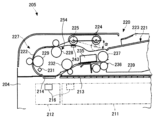
図17は、画像読取装置205の一例を示す拡大構成図である。
画像読取装置205は、フラットベッドスキャナモード(載置原稿読取りモード)と、DFスキャナモード(搬送原稿読取りモード)とに切替え可能に構成されている。
フラットベッドスキャナモードは、スキャナ部204の上部のフラットベッドコンタクトガラス213上に原稿が載置された状態で、コピー開始ボタン押下等の読取り開始要求操作がなされときに実行され、載置原稿の画像を読み取る動作モードである。フラットベッドコンタクトガラス213直下の移動読取領域211で画像読取部216を移動させながら、原稿の画像面に対して、光を照射する。そして、その原稿の画像面からの反射光を画像信号に変換することにより、原稿の画像を読み取るようになっている。
The present invention can also be applied to an ADF such as a document feeder of an image reading device.
FIG. 17 is an enlarged configuration diagram showing an example of the
The
The flatbed scanner mode is an operation mode in which an image of a document placed on the
また、DFスキャナモードは、画像読取部216を、DFコンタクトガラス214直下の停止読取領域212で停止させ、搬送原稿画像を読み取る動作モードである。
The DF scanner mode is an operating mode in which the
ADF220は、DFスキャナモードで、原稿載置トレイ221(原稿載置台)上に積載された原稿シート束から原稿シートを1枚ずつ分離して原稿搬送路222内に搬入し、原稿搬送路222に沿って搬送する。そして、その搬送中、原稿シートが、搬送方向の上流側部分から順次部分的にDFコンタクトガラス214の上面に対面するようになっている。
In the DF scanner mode, the
画像読取部216は、CCDモジュールもしくはCISモジュールなどのコンタクトガラス213、214上の所定の画像読取位置で、原稿の表面側の画像を繰り返しライン走査して、読み取ることができるものであればよい。また、停止読取領域212に固定した固定画像読取部と、移動読取領域211でフラットベッドコンタクトガラス213に沿って移動する移動読取部とをそれぞれ設けてもよい。
The
原稿載置トレイ221には、ADF220にセットされた原稿シートをその給紙方向と直交するシート幅方向で位置決めする左右の可動のサイドフェンス223が装着されている。これらサイドフェンス223は、原稿載置トレイ221と原稿シートの幅方向の中心を一致させるように相対的に接近および離隔可能である。ただし、サイドフェンス223は、原稿載置トレイ221の一方の縁部側に原稿シートの一方の縁部を当接させて他方の縁部側のみを移動可能に配置したものでもよい。
Mounted on the
ADF220は、原稿載置トレイ221上にセットされた原稿を給紙方向に呼び出す呼出ローラ224と、呼出ローラ224で給紙方向に呼び出された原稿を原稿搬送路222に向けて送るためのフィードローラ225および分離パッド243を備えている。
The
また、ADF220は、フィードローラ225によって原稿搬送路222内に給紙された原稿をDFコンタクトガラス214上に画像読取り可能な姿勢で搬送し、画像読取り後の原稿を排出口236まで搬送する搬送部227を備えている。
The
この搬送部227は、フィードローラ225等により分離・搬入された原稿シートを原稿搬送路222に沿って折り返すように反転させるとともに、DFコンタクトガラス214の上面の所定の読取位置を通過するように、原稿シートを搬送する。そのような原稿搬送のために、原稿搬送路222のうちDFコンタクトガラス214より上流側には、第一搬送ローラ228、第二搬送ローラ229と、原稿シートの搬送方向の先端を検知するレジストセンサ231とが設けられている。
This
フィードローラ225等により分離された原稿シートは、第一搬送ローラ228、第二搬送ローラ229によりDFコンタクトガラス214上を通るように搬送される。そして、レジストセンサ231による原稿シートの先端検知タイミングを基に、画像読取部216により適時に原稿表面画像が読み取られる。
The original sheet separated by the
原稿シートの裏面画像の読取りが要求される場合、裏面画像は、裏面読取用の密着型イメージセンサからなる裏面画像読取モジュール235(第二画像読取部)によって読み取られる。
読取り後の原稿は、排紙ローラ237により排紙トレイ239に排紙される。
When reading of the back side image of the document sheet is required, the back side image is read by a back side image reading module 235 (second image reading unit) consisting of a contact type image sensor for reading the back side.
After reading, the document is discharged onto a
フィードローラ225と第一搬送ローラ228との間には、原稿の有無を検知する反射型光学センサからなる突き当てセンサ254が配置している。この突き当てセンサ254によって原稿の先端を検知し、その後、更に搬送することで、原稿の先端は回転が停止している第一搬送ローラ228に突き当たる。突き当てセンサ72による原稿Sの先端の検知から所定時間だけ第一搬送ローラ228よりも上流側の搬送ローラを駆動し、その後停止する。これにより、原稿が所定量撓んで原稿スキューが補正される。
Between the
かかるADFにおいて、図14に示す構成と同様のセット検知部84を設ける。そして、セット検知部84のセットフィラー84aを検知する光学センサとして、突き当てセンサ254を用いる。原稿載置トレイ221上に原稿がセットされていないときは、セットフィラーは、図14に示す構成と同様、被検知部184bが突き当てセンサ254の検知領域に位置する第一の姿勢となっている。原稿載置トレイ221上に原稿がセットされセットフィラーが回動することで、セットフィラーが第二の姿勢となり、被検知部184bが突き当てセンサ254から退避する。これにより、突き当てセンサ254を用いて、原稿のセット検知が行える。原稿セット後においては、突き当てセンサ254は、原稿搬送路222の原稿を検知することができる。
In this ADF, a
以上に説明したものは一例であり、次の態様毎に特有の効果を奏する。
(態様1)
用紙などのシートが載置される手差しトレイ69などのシート載置部と、シート載置部に載置されたシートを給送する給紙ローラ61などの給送部材とを備え、シート載置部におけるシート幅方向所定の位置、および、シート搬送路におけるシート幅方向所定の位置で、シートの有無を検知する手差し給紙装置などのシート搬送装置において、手差し給紙路Rなどのシート搬送路のシートの有無を検知する光学センサ92と、シート載置部における幅方向所定位置にシートがないときは、第一姿勢をとり、シート載置部における幅方向所定位置にシートがあるときは、第二の姿勢をとるように揺動する幅検知フィラー91などの揺動部材とを備え、揺動部材は、第一姿勢あるいは第二姿勢をとるときに、光学センサ92で検知される被検知部91bを有する。
これによれば、ひとつの光学センサと、ひとつの揺動部材とで、シート載置部におけるシート幅方向所定の位置でシートの有無と、シート搬送路におけるシート幅方向所定の位置でシートの有無とを検知することができる。よって、シート載置部におけるシート幅方向所定の位置でシートの有無を検知する第一検知手段およびシート搬送路におけるシート幅方向所定の位置でシートの有無を検知する第二検知手段それぞれに、揺動部材と光学センサとを設ける特許文献1に記載の発明に比べて、部品点数を削減することができ、装置のコストダウンを図ることができる。
The above description is merely an example, and each of the following aspects provides unique effects.
(Aspect 1)
A sheet transport device such as a manual feed device that has a sheet mounting section such as a
According to this, one optical sensor and one swinging member can detect the presence or absence of a sheet at a predetermined position in the sheet width direction on the sheet placement section and the presence or absence of a sheet at a predetermined position in the sheet width direction on the sheet transport path. Therefore, compared to the invention described in
(態様2)
態様1において、幅検知フィラー91などの揺動部材は、規定幅以上のシートが手差しトレイ69などのシート載置部にセットされたとき、第二の姿勢を取り、光学センサ92は、規定幅以上のシートに対してシート搬送路のシートの有無を検知できるように配置し、第二の姿勢のときに被検知部91bが光学センサ92により検知される。
これによれば、実施形態で説明したように、規定幅以上のシートが手差しトレイ69などのシート載置部にスキューなくセットされたときは、光学センサ92は、被検知部91bを検知する。これにより、シート載置部に規定幅以上のシートがセットされたことを検知できる。また、光学センサ92は、被検知部91bを検知しなかったときは、シートを給送し、光学センサ92がシートを検知したら、規定幅以上のシートがスキューセットされたものであると判別できる。
(Aspect 2)
In
According to this, as described in the embodiment, when a sheet of a specified width or more is set without skew on a sheet placement section such as the
(態様3)
態様2において、手差しトレイ69などのシート載置部にセットするシート幅サイズをユーザーが入力する操作表示部48などの入力手段と、光学センサ92が被検知部91bを検知しているか否かの情報、光学センサ92のシートの検知結果とに基づいて、シート載置部にセットされたシート幅が、入力手段によりユーザーが入力したシート幅に合致しているか否かの判定を行う制御部300などの判定手段とを備える。
これによれば、実施形態で説明したように、本来、幅検知フィラー91などの揺動部材が第二の姿勢から第一の姿勢へ揺動し光学センサ92が被検知部91bを検知するはずの規定幅以上の用紙が、スキューセットで揺動部材が揺動しなかったとしても、光学センサ92が、搬送中のシートを検知すれば、手差しトレイ69などのシート載置部に載置されたシートが規定幅以上のシートであると判別できる。
これにより、光学センサ92が被検知部91bを検知しているか否かの情報のみでシート載置部にセットされたシート幅が、入力手段によりユーザーが入力したシート幅に合致しているか否かの判定を行うものに比べて、精度よく判定を行うことができる。
(Aspect 3)
In aspect 2, the device is provided with an input means such as an
According to this, as described in the embodiment, even if a sheet of paper of a specified width or more would normally be swung from the second position to the first position by a swung member such as the
This allows for a more accurate determination than a method that determines whether the sheet width set in the sheet loading section matches the sheet width input by the user via the input means based only on information on whether the
(態様4)
態様3において、制御部300などの判定手段は、光学センサ92が被検知部91bを検知、または、光学センサ92が手差し給紙路Rなどのシート搬送路のシートを検知したときは、シート載置部に規定幅以上のシートがセットされていると判別する。
これによれば、実施形態で説明したように、手差しトレイにセットされたシートが規定幅以上か否かを正確に判断できる。
(Aspect 4)
In aspect 3, a determination means such as the
According to this, as described in the embodiment, it is possible to accurately determine whether or not the sheet set on the manual feed tray is equal to or larger than the specified width.
(態様5)
態様3または4において、制御部300などの判定手段が、操作表示部48などの入力手段によりユーザーが入力したシート幅と手差しトレイ69などのシート載置部にセットされたシート幅とが異なると判定したときは、ユーザーが入力したシート幅とシート載置部にセットされたシート幅とが異なる旨を報知する。
これによれば、実施形態で説明したように、手差しトレイ69などのシート載置部にセットするシートの変更や、入力するシート幅の情報の変更をユーザーに促すことができる。
(Aspect 5)
In
This makes it possible to prompt the user to change the sheets to be set on the
(態様6)
態様1において、第一の姿勢のときに被検知部184bが光学センサ84bにより検知されるように構成し、光学センサ84bが被検知部検知状態から、非検知状態に切り替わったら、シート載置部にシートがセットされたと判定する。
光学センサ84bが被検知部184bの検知状態からシートセットを検知できる。また、シートセットを検知したときは、被検知部184bが光学センサ84bから退避しており、光学センサ84bにより手差し給紙路Rのシートの有無を検知できる。よって、この光学センサ84bのシート検知結果に基づいて、未達ジャム判定や、スキュー検知を行うことができる。
(Aspect 6)
In
The
(態様7)
態様6において、給紙ローラ61などの給送部材により手差しトレイ69などのシート載置部に載置されたシートの給送を開始してから所定時間経過しても、光学センサ84bがシートを検知しないときは、シートジャムが発生していると判定する。
これによれば、ひとつの光学センサで、シートセットの検知と、シートジャムの検知とを行うことができる。
(Aspect 7)
In aspect 6, if the
According to this, a single optical sensor can detect both the sheet setting and the sheet jam.
(態様8)
態様3乃至7いずれかにおいて、光学センサがシートを検知するタイミングに基づいてシートスキューを検知する制御部300などのスキュー検知手段と、シートスキューを補正する制御部300などのスキュー補正手段とを備え、スキュー補正手段は、スキュー検知手段の検知結果に基づいて、スキュー補正量を変更する。
これによれば、良好にシートのスキューを補正することができる。
(Aspect 8)
In any of aspects 3 to 7, a skew detection means such as the
This makes it possible to satisfactorily correct the skew of the sheet.
(態様9)
態様8において、制御部300などのスキュー検知手段は、理想到達時間T0などの予め決められた規定時間と、給紙開始タイミングなど規定のタイミングから光学センサがシートを検知するまでの時間との差分値から、シートスキュー量を検知する。
これによれば、シートのスキュー量を求めることができる。
(Aspect 9)
In
This makes it possible to obtain the amount of skew of the sheet.
(態様10)
態様9において、理想到達時間T0などの規定時間を補正する理想到達時間補正モードなどの規定時間補正モードを備える。
これによれば、実施形態で説明したように、部品のばらつきなどによる装置個々の特性のばらつき、経時使用による特性の変化の影響を加味した理想到達時間T0などの規定時間にすることができ、スキュー量の算出精度の低下を抑えることができる。
(Aspect 10)
In aspect 9, a specified time correction mode such as an ideal arrival time correction mode for correcting a specified time such as the ideal arrival time T0 is provided.
As a result, as described in the embodiment, it is possible to set a specified time such as the ideal arrival time T0 that takes into account the effects of variations in the characteristics of individual devices due to component variations and changes in characteristics due to use over time, thereby suppressing any decrease in the accuracy of calculating the amount of skew.
(態様11)
態様8において、光学センサ92の配置位置とは、シート搬送路の幅方向中央を挟んで反対側の位置に第二光学センサを配置し、制御部などのスキュー検知手段は、光学センサおよび第二光学センサのいずれか一方の光学センサがシートを検知してから他方の光学センサシートを検知するまでの時間からシートスキューを検知する。
これによれば、手差しトレイ69などのシート載置部のシートの先端位置のばらつきの影響を受けずに、スキュー量を算出することができ、スキュー量の算出精度を高めることができる。また、光学センサと第二光学センサのうちのどちらかが最初のシートを検知したかで、スキューの方向も検知できる。
(Aspect 11)
In
This makes it possible to calculate the amount of skew without being affected by variations in the leading edge position of the sheet on the sheet placement unit such as the
(態様12)
原稿を搬送するADF220などの原稿搬送装置を備え、原稿搬送装置によって搬送される原稿の原稿画像を読み取る画像読取装置205において、原稿搬送装置として、態様1乃至11いずれかのシート搬送装置を用いた。
これによれば、部品点数の削減を図ることができ、装置のコストダウンを図ることができる。
(Aspect 12)
In an
This allows a reduction in the number of parts, leading to a reduction in the cost of the device.
(態様13)
シートを搬送するシート搬送装置を備え、シート搬送装置によって搬送されるシートに画像を形成する画像形成装置において、シート搬送装置として、態様1乃至11いずれかのシート搬送装置を用いた。
これによれば、部品点数の削減を図ることができ、装置のコストダウンを図ることができる。
(Aspect 13)
In an image forming apparatus including a sheet transporting device that transports a sheet and forms an image on a sheet transported by the sheet transporting device, the sheet transporting device according to any one of
This allows a reduction in the number of parts, leading to a reduction in the cost of the device.
48 :操作表示部
61 :給紙ローラ
62 :底板
63 :スプリング
64 :摩擦部材
65 :保持部材
66 :スプリング
68 :搬送ガイド部材
68a :壁部
69 :手差しトレイ
69a :サイドフェンス
70 :給紙ローラ軸
71 :カム
72 :突き当てセンサ
84 :セット検知部
84a :セットフィラー
84b :光学センサ
85 :駆動モータ
90 :幅検知部
91 :幅検知フィラー
91a :回動軸
91b :被検知部
91c :切り欠き
91d :用紙突き当て面
92 :光学センサ
184a :回動軸
184b :被検知部
184c :切り欠き
184d :用紙突き当て面
204 :スキャナ部
205 :画像読取装置
220 :ADF
300 :制御部
L :レーザ光
P :用紙
R :手差し給紙路
S :原稿
T :計測時間
T0 :理想到達時間
48: Operation display unit 61: Paper feed roller 62: Bottom plate 63: Spring 64: Friction member 65: Holding member 66: Spring 68:
300: Control unit L: Laser light P: Paper R: Manual feed path S: Document T: Measurement time T0: Ideal arrival time
Claims (13)
前記シート載置部に載置されたシートを給送する給送部材とを備え、
前記シート載置部におけるシート幅方向所定の位置、および、シート搬送路におけるシート幅方向所定の位置で、シートの有無を検知するシート搬送装置において、
前記シート搬送路の前記シートの有無を検知する光学センサと、
前記シート載置部における幅方向所定位置にシートがないときは、第一の姿勢をとり、前記シート載置部における幅方向所定位置にシートがあるときは、第二の姿勢をとるように揺動する揺動部材とを備え、
前記揺動部材は、前記第一の姿勢あるいは前記第二の姿勢をとるときに、前記光学センサで検知される被検知部を有することを特徴とするシート搬送装置。 a sheet placement section on which a sheet is placed;
a feeding member that feeds a sheet placed on the sheet placement section,
A sheet conveying device that detects the presence or absence of a sheet at a predetermined position in a sheet width direction on the sheet placement unit and at a predetermined position in a sheet width direction on the sheet conveying path,
an optical sensor that detects the presence or absence of the sheet on the sheet transport path;
a swinging member that swings to take a first position when no sheet is present at a predetermined widthwise position on the sheet placement section, and to take a second position when a sheet is present at a predetermined widthwise position on the sheet placement section,
The sheet conveying device according to claim 1, wherein the swingable member has a detection target portion that is detected by the optical sensor when the swingable member is in the first position or the second position.
前記揺動部材は、規定幅以上のシートが前記シート載置部にセットされたとき、前記第二の姿勢を取り、
前記光学センサは、規定幅以上のシートに対してシート搬送路のシートの有無を検知できるように配置し、
前記第二の姿勢のときに前記被検知部が前記光学センサにより検知されることを特徴とするシート搬送装置。 2. The sheet conveying apparatus according to claim 1,
The swinging member takes the second position when a sheet having a width equal to or larger than a specified width is set on the sheet placement portion,
the optical sensor is arranged so as to be able to detect the presence or absence of a sheet on the sheet transport path for a sheet having a width equal to or greater than a specified width;
the detection portion is detected by the optical sensor when the sheet is in the second position.
前記シート載置部にセットするシート幅サイズをユーザーが入力する入力手段と、前記光学センサが前記被検知部を検知しているか否かの情報と、前記光学センサのシートの検知結果とに基づいて、前記シート載置部にセットされたシート幅が、前記入力手段によりユーザーが入力したシート幅に合致しているか否かの判定を行う判定手段とを備えることを特徴とするシート搬送装置。 3. The sheet conveying apparatus according to claim 2,
A sheet conveying device characterized by comprising an input means for a user to input the sheet width size to be set in the sheet loading section, and a judgment means for determining whether the sheet width set in the sheet loading section matches the sheet width input by the user via the input means based on information on whether the optical sensor detects the detected section and the sheet detection result of the optical sensor.
前記判定手段は、前記光学センサが前記被検知部を検知、または、前記光学センサがシート搬送路のシートを検知したときは、前記シート載置部に規定幅以上のシートがセットされていると判別することを特徴とするシート搬送装置。 4. The sheet conveying apparatus according to claim 3,
The sheet transport device is characterized in that the determination means determines that a sheet of a specified width or more is set in the sheet loading section when the optical sensor detects the detected portion or when the optical sensor detects a sheet in the sheet transport path.
前記判定手段が、前記入力手段によりユーザーが入力したシート幅と前記シート載置部にセットされたシート幅とが異なると判定したときは、ユーザーが入力したシート幅と前記シート載置部にセットされたシート幅とが異なる旨を報知することを特徴とするシート搬送装置。 5. The sheet conveying apparatus according to claim 3,
When the determination means determines that the sheet width input by the user via the input means is different from the sheet width set in the sheet loading section, the sheet conveying device notifies the user that the sheet width input by the user is different from the sheet width set in the sheet loading section.
前記第一の姿勢のときに前記被検知部が前記光学センサにより検知されるように構成し、
前記光学センサが前記被検知部検知状態から、非検知状態に切り替わったら、前記シート載置部にシートがセットされたと判定することを特徴とするシート搬送装置。 2. The sheet conveying apparatus according to claim 1,
The detection portion is configured to be detected by the optical sensor when the detection portion is in the first position,
a detection unit configured to detect a sheet placed on the sheet placement portion when the optical sensor is switched from a detection state of the detection portion to a non-detection state of the detection portion;
前記給送部材により前記シート載置部に載置されたシートの給送を開始してから所定時間経過しても、前記光学センサがシート搬送路上のシートを検知しないときは、シートジャムが発生していると判定することを特徴とするシート搬送装置。 7. The sheet conveying apparatus according to claim 6,
A sheet conveying device characterized in that when the optical sensor does not detect a sheet on the sheet conveying path even after a predetermined time has elapsed since the feeding member starts feeding the sheet placed on the sheet loading section, it is determined that a sheet jam has occurred.
前記光学センサがシートを検知するタイミングに基づいてシートスキューを検知するスキュー検知手段と、
前記シートスキューを補正するスキュー補正手段とを備え、
前記スキュー補正手段は、前記スキュー検知手段の検知結果に基づいて、スキュー補正量を変更することを特徴とするシート搬送装置。 The sheet conveying device according to any one of claims 3 to 7,
a skew detection unit that detects a sheet skew based on a timing at which the optical sensor detects the sheet;
a skew correction means for correcting the sheet skew,
The sheet conveying device according to claim 1, wherein the skew correction means changes an amount of skew correction based on a detection result of the skew detection means.
前記スキュー検知手段は、予め決められた規定時間と、規定のタイミングから前記光学センサがシートを検知するまでの時間との差分値から、シートスキュー量を検知することを特徴とするシート搬送装置。 9. The sheet conveying apparatus according to claim 8,
The sheet conveying device, wherein the skew detection means detects the amount of sheet skew from a difference between a predetermined specified time and a time from a specified timing until the optical sensor detects the sheet.
前記規定時間を補正する規定時間補正モードを備えることを特徴とするシート搬送装置。 10. The sheet transport device according to claim 9,
The sheet conveying device further comprises a specified time correction mode for correcting the specified time.
前記光学センサの配置位置とはシート搬送路の幅方向中央を挟んで反対側の位置に第二光学センサを配置し、
前記スキュー検知手段は、前記光学センサおよび前記第二光学センサのいずれか一方の光学センサがシートを検知してから他方の光学センサシートを検知するまでの時間からシートスキューを検知することを特徴とするシート搬送装置。 9. The sheet conveying apparatus according to claim 8,
a second optical sensor is disposed at a position opposite to the position of the optical sensor across the center of the sheet conveying path in the width direction;
A sheet conveying device characterized in that the skew detection means detects sheet skew from the time from when one of the optical sensor and the second optical sensor detects the sheet to when the other optical sensor detects the sheet.
前記原稿搬送装置によって搬送される前記原稿の原稿画像を読み取る画像読取装置において、
前記原稿搬送装置として、請求項1乃至11いずれか一項に記載のシート搬送装置を用いたことを特徴とする画像読取装置。 A document transport device for transporting a document,
In an image reading apparatus for reading an original image of the original conveyed by the original conveying device,
12. An image reading apparatus, comprising: the sheet transport device according to claim 1 as the document transport device.
前記シート搬送装置によって搬送される前記シートに画像を形成する画像形成装置において、
前記シート搬送装置として、請求項1乃至11いずれか一項に記載のシート搬送装置を用いたことを特徴とする画像形成装置。 A sheet conveying device is provided for conveying a sheet,
an image forming apparatus for forming an image on the sheet conveyed by the sheet conveying device,
12. An image forming apparatus, comprising: the sheet transport device according to claim 1 as the sheet transport device.
Priority Applications (2)
| Application Number | Priority Date | Filing Date | Title |
|---|---|---|---|
| JP2020102099A JP7535239B2 (en) | 2020-06-12 | 2020-06-12 | Sheet conveying device, image reading device and image forming device |
| US17/337,862 US11691833B2 (en) | 2020-06-12 | 2021-06-03 | Sheet conveying device, image reading device incorporating the sheet conveying device, and image forming apparatus incorporating the sheet conveying device |
Applications Claiming Priority (1)
| Application Number | Priority Date | Filing Date | Title |
|---|---|---|---|
| JP2020102099A JP7535239B2 (en) | 2020-06-12 | 2020-06-12 | Sheet conveying device, image reading device and image forming device |
Publications (2)
| Publication Number | Publication Date |
|---|---|
| JP2021195208A JP2021195208A (en) | 2021-12-27 |
| JP7535239B2 true JP7535239B2 (en) | 2024-08-16 |
Family
ID=78824454
Family Applications (1)
| Application Number | Title | Priority Date | Filing Date |
|---|---|---|---|
| JP2020102099A Active JP7535239B2 (en) | 2020-06-12 | 2020-06-12 | Sheet conveying device, image reading device and image forming device |
Country Status (2)
| Country | Link |
|---|---|
| US (1) | US11691833B2 (en) |
| JP (1) | JP7535239B2 (en) |
Families Citing this family (3)
| Publication number | Priority date | Publication date | Assignee | Title |
|---|---|---|---|---|
| JP7483526B2 (en) * | 2020-06-24 | 2024-05-15 | キヤノン株式会社 | Image forming device |
| JP7627439B2 (en) * | 2021-03-17 | 2025-02-06 | 株式会社リコー | Feeding device and image forming apparatus |
| JP7739936B2 (en) * | 2021-10-22 | 2025-09-17 | 京セラドキュメントソリューションズ株式会社 | feeding device |
Citations (2)
| Publication number | Priority date | Publication date | Assignee | Title |
|---|---|---|---|---|
| JP2014236298A (en) | 2013-05-31 | 2014-12-15 | 京セラドキュメントソリューションズ株式会社 | Sheet conveyance device, image reader, and image forming apparatus |
| JP2018188256A (en) | 2017-05-02 | 2018-11-29 | 株式会社リコー | Feeding apparatus and image forming apparatus |
Family Cites Families (23)
| Publication number | Priority date | Publication date | Assignee | Title |
|---|---|---|---|---|
| JPS5755080A (en) | 1980-09-20 | 1982-04-01 | Nihon Dennetsu Keiki Kk | Method of treating coated lead wire |
| JPS6443435A (en) | 1987-08-11 | 1989-02-15 | Minolta Camera Kk | Paper skew detecting device |
| JPH05341604A (en) | 1992-06-10 | 1993-12-24 | Canon Inc | Copying device |
| JP2004155522A (en) | 2002-11-01 | 2004-06-03 | Ricoh Co Ltd | Image forming device |
| JP4255700B2 (en) * | 2003-01-24 | 2009-04-15 | 株式会社沖データ | Image forming apparatus |
| JP2005263402A (en) | 2004-03-18 | 2005-09-29 | Fuji Xerox Co Ltd | Recording sheet detecting device, and fixing device and image forming device using detecting device |
| JP4677380B2 (en) | 2006-08-03 | 2011-04-27 | 株式会社リコー | Case cover opening / closing mechanism |
| JP4713451B2 (en) | 2006-12-07 | 2011-06-29 | 株式会社リコー | Sliding mechanism, paper guide, paper stacking device, manual paper feed tray, and image forming apparatus |
| US8095062B2 (en) * | 2007-09-07 | 2012-01-10 | Lexmark International, Inc. | Media width sensors containing axially spaced paddles and method of using the media width sensor |
| JP2009196764A (en) | 2008-02-21 | 2009-09-03 | Canon Inc | Image forming device and its control method |
| JP2011016658A (en) | 2009-06-11 | 2011-01-27 | Ricoh Co Ltd | Sheet transport mechanism and electrophotographic image forming apparatus incorporating the same |
| KR101725093B1 (en) * | 2009-12-24 | 2017-04-10 | 에스프린팅솔루션 주식회사 | Image forming apparatus |
| JP2011197237A (en) | 2010-03-18 | 2011-10-06 | Ricoh Co Ltd | Image forming apparatus and method for controlling the same |
| JP5696460B2 (en) | 2010-12-10 | 2015-04-08 | 株式会社リコー | Sheet feeding apparatus and image forming apparatus |
| JP5904397B2 (en) | 2011-11-01 | 2016-04-13 | 株式会社リコー | Sheet conveying apparatus and image forming apparatus |
| JP6124539B2 (en) | 2012-09-06 | 2017-05-10 | キヤノン株式会社 | Image forming apparatus |
| JP6083501B2 (en) | 2012-10-01 | 2017-02-22 | 株式会社リコー | Sheet conveying apparatus, sheet discharging apparatus, and image forming apparatus |
| JP5927171B2 (en) | 2013-12-25 | 2016-06-01 | 京セラドキュメントソリューションズ株式会社 | Sheet conveying mechanism, document conveying apparatus, and image forming apparatus including the same |
| JP2016023031A (en) * | 2014-07-18 | 2016-02-08 | キヤノン株式会社 | Sheet feeding device and printer |
| JP6432773B2 (en) | 2014-12-15 | 2018-12-05 | 株式会社リコー | Recording medium conveying apparatus and image forming apparatus |
| US10514649B2 (en) * | 2016-03-25 | 2019-12-24 | Canon Kabushiki Kaisha | Image forming apparatus |
| JP6957209B2 (en) * | 2017-05-31 | 2021-11-02 | キヤノン株式会社 | Image forming device |
| JP7320190B2 (en) | 2019-07-31 | 2023-08-03 | 株式会社リコー | Sheet guide device and image forming device |
-
2020
- 2020-06-12 JP JP2020102099A patent/JP7535239B2/en active Active
-
2021
- 2021-06-03 US US17/337,862 patent/US11691833B2/en active Active
Patent Citations (2)
| Publication number | Priority date | Publication date | Assignee | Title |
|---|---|---|---|---|
| JP2014236298A (en) | 2013-05-31 | 2014-12-15 | 京セラドキュメントソリューションズ株式会社 | Sheet conveyance device, image reader, and image forming apparatus |
| JP2018188256A (en) | 2017-05-02 | 2018-11-29 | 株式会社リコー | Feeding apparatus and image forming apparatus |
Also Published As
| Publication number | Publication date |
|---|---|
| US20210387823A1 (en) | 2021-12-16 |
| JP2021195208A (en) | 2021-12-27 |
| US11691833B2 (en) | 2023-07-04 |
Similar Documents
| Publication | Publication Date | Title |
|---|---|---|
| JP7535239B2 (en) | Sheet conveying device, image reading device and image forming device | |
| JP4670933B2 (en) | Image forming apparatus | |
| CN114815554B (en) | Transfer unit and image forming device having the same | |
| JP6245862B2 (en) | Image forming apparatus | |
| JP5311279B2 (en) | Paper thickness detection device, paper feeding / conveying device, image reading device, image forming device | |
| US8509666B2 (en) | Fixing device and image forming apparatus | |
| KR100565094B1 (en) | Paper detection device and image forming device having same | |
| JP5212808B2 (en) | Paper feeding device and image forming apparatus. | |
| JP4515831B2 (en) | Development density control method and image forming apparatus | |
| JP6801026B2 (en) | Image forming device, recording material discrimination sensor | |
| JP6233683B2 (en) | Feeding apparatus, image forming apparatus, and image reading apparatus | |
| JP2010175840A (en) | Image forming apparatus | |
| JP2025070843A (en) | Image forming device | |
| JP7135784B2 (en) | MEDIUM THICKNESS DETECTION DEVICE, MEDIUM CONVEYING DEVICE, AND IMAGE FORMING APPARATUS | |
| JPH07261591A (en) | Image forming device | |
| JP6061190B2 (en) | Belt misalignment correction mechanism, belt device, transfer belt device, and image forming apparatus | |
| JP7254571B2 (en) | image forming device | |
| JP4975518B2 (en) | Image forming apparatus | |
| JPH0840621A (en) | Electrophotographic equipment | |
| JP4717723B2 (en) | Recording material detector | |
| JP4481026B2 (en) | Belt drive device and image forming apparatus having the same | |
| JP2012168298A (en) | Thickness detecting device, image forming device, image forming method, image forming program and recording medium | |
| JP3740864B2 (en) | Image forming apparatus | |
| JP2006030736A (en) | Color image forming apparatus | |
| JP5075643B2 (en) | Fixing apparatus and image forming apparatus having the same |
Legal Events
| Date | Code | Title | Description |
|---|---|---|---|
| A621 | Written request for application examination |
Free format text: JAPANESE INTERMEDIATE CODE: A621 Effective date: 20230412 |
|
| A977 | Report on retrieval |
Free format text: JAPANESE INTERMEDIATE CODE: A971007 Effective date: 20240220 |
|
| A131 | Notification of reasons for refusal |
Free format text: JAPANESE INTERMEDIATE CODE: A131 Effective date: 20240301 |
|
| A521 | Request for written amendment filed |
Free format text: JAPANESE INTERMEDIATE CODE: A523 Effective date: 20240424 |
|
| TRDD | Decision of grant or rejection written | ||
| A01 | Written decision to grant a patent or to grant a registration (utility model) |
Free format text: JAPANESE INTERMEDIATE CODE: A01 Effective date: 20240705 |
|
| A61 | First payment of annual fees (during grant procedure) |
Free format text: JAPANESE INTERMEDIATE CODE: A61 Effective date: 20240718 |
|
| R150 | Certificate of patent or registration of utility model |
Ref document number: 7535239 Country of ref document: JP Free format text: JAPANESE INTERMEDIATE CODE: R150 |