JP4717723B2 - Recording material detector - Google Patents
Recording material detector Download PDFInfo
- Publication number
- JP4717723B2 JP4717723B2 JP2006158639A JP2006158639A JP4717723B2 JP 4717723 B2 JP4717723 B2 JP 4717723B2 JP 2006158639 A JP2006158639 A JP 2006158639A JP 2006158639 A JP2006158639 A JP 2006158639A JP 4717723 B2 JP4717723 B2 JP 4717723B2
- Authority
- JP
- Japan
- Prior art keywords
- recording material
- sheet material
- roller
- sensor
- reference body
- Prior art date
- Legal status (The legal status is an assumption and is not a legal conclusion. Google has not performed a legal analysis and makes no representation as to the accuracy of the status listed.)
- Expired - Fee Related
Links
Images


Classifications
-
- B—PERFORMING OPERATIONS; TRANSPORTING
- B41—PRINTING; LINING MACHINES; TYPEWRITERS; STAMPS
- B41J—TYPEWRITERS; SELECTIVE PRINTING MECHANISMS, i.e. MECHANISMS PRINTING OTHERWISE THAN FROM A FORME; CORRECTION OF TYPOGRAPHICAL ERRORS
- B41J29/00—Details of, or accessories for, typewriters or selective printing mechanisms not otherwise provided for
- B41J29/38—Drives, motors, controls or automatic cut-off devices for the entire printing mechanism
- B41J29/393—Devices for controlling or analysing the entire machine ; Controlling or analysing mechanical parameters involving printing of test patterns
-
- B—PERFORMING OPERATIONS; TRANSPORTING
- B41—PRINTING; LINING MACHINES; TYPEWRITERS; STAMPS
- B41J—TYPEWRITERS; SELECTIVE PRINTING MECHANISMS, i.e. MECHANISMS PRINTING OTHERWISE THAN FROM A FORME; CORRECTION OF TYPOGRAPHICAL ERRORS
- B41J11/00—Devices or arrangements of selective printing mechanisms, e.g. ink-jet printers or thermal printers, for supporting or handling copy material in sheet or web form
- B41J11/0035—Handling copy materials differing in thickness
-
- B—PERFORMING OPERATIONS; TRANSPORTING
- B41—PRINTING; LINING MACHINES; TYPEWRITERS; STAMPS
- B41J—TYPEWRITERS; SELECTIVE PRINTING MECHANISMS, i.e. MECHANISMS PRINTING OTHERWISE THAN FROM A FORME; CORRECTION OF TYPOGRAPHICAL ERRORS
- B41J11/00—Devices or arrangements of selective printing mechanisms, e.g. ink-jet printers or thermal printers, for supporting or handling copy material in sheet or web form
- B41J11/0095—Detecting means for copy material, e.g. for detecting or sensing presence of copy material or its leading or trailing end
-
- B—PERFORMING OPERATIONS; TRANSPORTING
- B41—PRINTING; LINING MACHINES; TYPEWRITERS; STAMPS
- B41J—TYPEWRITERS; SELECTIVE PRINTING MECHANISMS, i.e. MECHANISMS PRINTING OTHERWISE THAN FROM A FORME; CORRECTION OF TYPOGRAPHICAL ERRORS
- B41J13/00—Devices or arrangements of selective printing mechanisms, e.g. ink-jet printers or thermal printers, specially adapted for supporting or handling copy material in short lengths, e.g. sheets
- B41J13/0009—Devices or arrangements of selective printing mechanisms, e.g. ink-jet printers or thermal printers, specially adapted for supporting or handling copy material in short lengths, e.g. sheets control of the transport of the copy material
- B41J13/0018—Devices or arrangements of selective printing mechanisms, e.g. ink-jet printers or thermal printers, specially adapted for supporting or handling copy material in short lengths, e.g. sheets control of the transport of the copy material in the sheet input section of automatic paper handling systems
-
- B—PERFORMING OPERATIONS; TRANSPORTING
- B41—PRINTING; LINING MACHINES; TYPEWRITERS; STAMPS
- B41J—TYPEWRITERS; SELECTIVE PRINTING MECHANISMS, i.e. MECHANISMS PRINTING OTHERWISE THAN FROM A FORME; CORRECTION OF TYPOGRAPHICAL ERRORS
- B41J13/00—Devices or arrangements of selective printing mechanisms, e.g. ink-jet printers or thermal printers, specially adapted for supporting or handling copy material in short lengths, e.g. sheets
- B41J13/009—Diverting sheets at a section where at least two sheet conveying paths converge, e.g. by a movable switching guide that blocks access to one conveying path and guides the sheet to another path, e.g. when a sheet conveying direction is reversed after printing on the front of the sheet has been finished and the sheet is guided to a sheet turning path for printing on the back
Description
本発明はプリンタ、複写機など画像形成装置に適用される記録材検知装置に関するものであり、特に検知手段からの出力を補正するための基準部材に関するものである。 The present invention relates to a recording material detection apparatus applied to an image forming apparatus such as a printer or a copying machine, and more particularly to a reference member for correcting an output from a detection means.
画像形成装置に用いられる記録材であるシート材には、いわゆる普通コピー用紙(普通紙)、プロジェクター用透明フィルムや高画質画像を得るための白色フィルムなど多数ある。更に普通紙にも厚さが色々あり、例えば坪量60g/m2のものもあれば200g/m2のものもある。 There are many sheet materials that are recording materials used in image forming apparatuses, such as so-called ordinary copy paper (plain paper), transparent films for projectors, and white films for obtaining high-quality images. Furthermore, there are various thicknesses of plain paper, for example, some having a basis weight of 60 g / m 2 and others having a basis weight of 200 g / m 2 .
これら多種多様なシート材のいずれに対しても良好な画像を得るには、シート材ごとに画像形成条件を変更しなければならない。例えば、電子写真方式の画像形成装置では、転写時、抵抗値の低い普通紙には低いバイアスを、抵抗値の高いグロスフィルムには高いバイアスを印加するといった、シート材の抵抗値に合わせて最適なバイアスを印加することが必要である。また、定着時には、熱容量の低い普通紙には低い温度で、熱容量の大きいグロスフィルムには高い温度で定着を行うといった、シート材の熱容量に合わせて最適な定着温度に設定することが必要である。この様に、シート材の種類によらずにより良好な画像を得るためには、そのシート材の種類を検知しなけばならない。その検知のためには光学式センサを用いることが一般的に行なわれている。 In order to obtain a good image on any of these various sheet materials, the image forming conditions must be changed for each sheet material. For example, in an electrophotographic image forming apparatus, at the time of transfer, a low bias is applied to plain paper having a low resistance value, and a high bias is applied to a gloss film having a high resistance value. It is necessary to apply a proper bias. Also, at the time of fixing, it is necessary to set the optimal fixing temperature according to the heat capacity of the sheet material, such as fixing at a low temperature for plain paper with a low heat capacity and at a high temperature for a gloss film with a large heat capacity. . Thus, in order to obtain a better image regardless of the type of sheet material, the type of the sheet material must be detected. An optical sensor is generally used for the detection.
一方、搬送されてくるシート材の表面を読み取る光学式センサの読み取り精度は、センサ毎の違い、取り付け位置の精度、及び耐久による劣化等で、ばらつきを生じる。これらのばらつきを補正する為には、基準体を読み取ることで、センサからの出力を補正することが行われている。この補正は、搬送されてくるシート材と略同一平面(搬送面)で行われることが望ましいため、基準体を搬送されてくるシート材と略同一面に設置することがよく、その結果として、シート材の搬送によって、基準体の表面に汚れや傷が付くといった問題があった。 On the other hand, the reading accuracy of the optical sensor that reads the surface of the conveyed sheet material varies due to differences among the sensors, the accuracy of the mounting position, deterioration due to durability, and the like. In order to correct these variations, the output from the sensor is corrected by reading the reference body. Since it is desirable that this correction is performed in substantially the same plane (conveying surface) as the sheet material being conveyed, it is preferable to install the reference body substantially in the same plane as the sheet material being conveyed. There is a problem that the surface of the reference body is soiled or scratched by the conveyance of the sheet material.
この光学式センサにおける基準体の汚れや傷の問題を解決するため、従来は基準体を移動自在な支持部材で支持し、基準体を搬送面以外の位置に退避させるため支持部材を駆動手段で駆動していた。つまり駆動手段によって支持部材を移動し、基準体を搬送面以外の位置に退避させた後で、シート材を搬送面に移動することを行っていた(特許文献1参照)。
しかしながら、上記従来例では、基準体の移動に駆動手段を用いているため、モータ等が別途必要となり、コストアップや装置構成が複雑になるといった問題があった。 However, in the above conventional example, since the driving means is used to move the reference body, a motor or the like is required separately, and there is a problem that the cost is increased and the apparatus configuration is complicated.
上記課題を解決するため本発明は、記録材に光を照射し記録材から得られる光を検知する検知手段と、前記検知手段からの出力を補正するため前記検知手段によって検知される基準部を備えた基準部材と、を有し、前記基準部材は前記検知手段による検知位置から移動可能である記録材検知装置において、前記基準部材は、記録材によって移動することを特徴とするものである。 In order to solve the above-mentioned problems, the present invention provides a detection means for detecting light obtained by irradiating a recording material with light and a reference portion detected by the detection means for correcting the output from the detection means. In the recording material detection apparatus, wherein the reference member is movable from the detection position by the detection means, the reference member is moved by the recording material.
本発明によれば、基準部の移動に記録材そのものを利用することで、駆動手段であるモータ等が必要なくなり、大幅に装置本体のコストダウンや装置構成の簡略化を行うことができる。 According to the present invention, by using the recording material itself for the movement of the reference portion, a motor or the like as a driving unit is not necessary, and the cost of the apparatus main body can be greatly reduced and the apparatus configuration can be greatly simplified.
(実施例1)
以下に、本発明に係る画像形成装置の第1実施例を図1〜図7を用いて説明する。
Example 1
A first embodiment of an image forming apparatus according to the present invention will be described below with reference to FIGS.
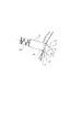
図1において、1は給紙カセット、2は給紙ローラ、3は搬送手段であるレジストローラ、21はレジストローラの対向ローラである対向コロ、19はシート材(記録材)Pの表面状態を検知する検知手段である光学式センサである。センサ19は、レジストローラ3と対向コロ21が当接するニップ部に対応する位置に設けられている。センサ19は、シート材に光を照射し、シート材から得られる光を検知することによりシート材の表面性、厚み等を検知する。
In FIG. 1, 1 is a paper feed cassette, 2 is a paper feed roller, 3 is a registration roller which is a conveying means, 21 is a counter roller which is a counter roller of the registration roller, and 19 is a surface state of a sheet material (recording material) P. It is an optical sensor which is a detection means to detect. The
レジストローラ周辺の斜視図である図2において、22はレジストローラ3と同軸上に揺動可能に支持された、シート材の斜行を補正するレジストシャッタである。このレジストシャッタ22にはレジストローラ3と対向ローラ21のニップ部よりも対向コロ21側に突出した突当部22Bが紙幅方向で6箇所並んで設けられている。このレジストシャッタ22の中央部には基準体(基準部)である平板22Kが設けられており、この平板22Kはセンサ19の対向位置に配置されている。
In FIG. 2, which is a perspective view of the periphery of the registration roller,
平板22Kは、センサ19の出力を補正するため、センサ19によって予め検知され基準となる出力を得るためのものである。この平板22Kは上述した様にレジストシャッタ22に設けられており、レジストシャッタ22は平板22Kを支持する支持部材であり、言い換えると基準体(平板22K)を有する基準部材である。つまりこのレジストシャッタ22には基準体22Kが設けられており、レジストシャッタ22は、シート材の斜行補正の他に、センサの出力補正に寄与している。この基準部材はレジストシャッタ22であるので、センサによる検知位置から移動可能である。
The
図1において、4は定着器、5は排紙ローラ、6は排紙トレイ、7〜10は感光ドラム、11は露光手段であるレーザスキャナである。感光ドラム7〜10は、レーザスキャナ11による露光によって潜像が形成され、この潜像が形成された感光ドラム7〜10はそれぞれイエロー、マゼンタ、シアン、ブラックのトナーで不図示の現像手段によって現像される。また、12は中間転写ベルト、13〜16は一次転写手段である一次転写ローラであり、一次転写ローラ13〜16は中間転写ベルト12を介して感光ドラム7〜10と当接し、中間転写ベルト12は図中矢印Aの方向に回転移動する。中間転写ベルト12は2軸構成で、駆動ローラ17とベルトにテンションを付与するテンションローラ20に掛け回されている。駆動ローラ17は二次転写手段である二次転写ローラ18の対向に配置された対向ローラでもある。
In FIG. 1, 4 is a fixing device, 5 is a paper discharge roller, 6 is a paper discharge tray, 7 to 10 are photosensitive drums, and 11 is a laser scanner as exposure means. The photosensitive drums 7 to 10 are formed with latent images by exposure by the laser scanner 11, and the photosensitive drums 7 to 10 on which the latent images are formed are developed by developing means (not shown) with toners of yellow, magenta, cyan, and black, respectively. Is done. Further, 12 is an intermediate transfer belt, and 13 to 16 are primary transfer rollers as primary transfer means. The
次にシート材の表面状態を検知するセンサ19の固定方法について、図2を用いて更に説明する。シート材の表面状態を検知するセンサ19は左右に配置されたレジストローラの対向コロ21の間(中央部)に、対向コロ軸23、24を分断して配置されている。対向コロ21の中央部に配置されたセンサ19は、左右の対向コロ軸23、24を保持するコロホルダ25に固定され、対向コロ21と一体的に加圧バネ26によって、レジストローラ3側に加圧されている。
Next, a method of fixing the
次に動作について説明する。シート材がレジストローラと対向ローラのニップ部に搬送されてくる前は、レジストシャッタ22は図3に示した位置にある。そしてレジストシャッタ22に設けられた平板22Kは、センサ19に対向する搬送路内の読み取り位置(検知位置)にある。この状態で、平板22Kをセンサ19で読み取ることで、初期に読み取った値との差を算出し、センサの出力を補正する。この後、給紙カセット1から給紙ローラ2によって供給されたシート材Pの先端が、レジストシャッタ22の突当部22Bに当接する(図4)。その後、図5に示す様に、シート材Pはそのコシで、矢印Sの方向に、レジストシャッタ22を回転させながら、レジストローラ3と対向コロ21のニップ部に到達する。この後、ニップ部に入ったシート材Pは、一定量搬送され図6に示す状態で停止する。この状態になると平板22Kはレジストシャッタ22と共に大きく回転しているので、平板22Kのセンサ19による読取面22KSは、搬送面から移動し、シート材Pに接触しない退避位置に位置している。
Next, the operation will be described. Before the sheet material is conveyed to the nip portion between the registration roller and the counter roller, the
このため、引き続きシート材を搬送してもシート材によって平板22Kの基準面22KSがシート材で摺擦することがないため、平板22Kが傷ついたり、汚れたりすることはない。
For this reason, even if the sheet material is continuously conveyed, the reference surface 22KS of the
ここで、レーザスキャナ11によって露光され、その後、現像された感光ドラム7〜10上のトナー画像は、駆動ローラ17によって駆動された中間転写ベルト12が走行することで、順次一次転写ローラ13〜16によって中間転写ベルト上に転写されていく。このとき、シート材の表面状態を検知するセンサ19で、シート材の表面状態の検知は実行される。
Here, the toner images on the photosensitive drums 7 to 10 exposed by the laser scanner 11 and then developed are sequentially transferred to the
その後、転写されたベルト上のトナー画像に合わせて、搬送手段であるレジストローラ3を回転させ、一旦停止させたシート材を二次転写手段である二次転写ローラ18のニップ部に搬送する。
Thereafter, the
予め平板22Kで補正したセンサ19で検知されたシート材の表面状態に基づき、最適な転写条件で、トナー画像が転写されたシート材は、定着器4によって未定着トナー画像が定着され、排紙ローラ5によって排紙トレイ6上に排出される。
Based on the surface condition of the sheet material detected by the
この時、図7に示すようにシート材の後端が、レジストシャッタ22の突当部22Bから抜けると、レジストシャッタ22は、バネ力で元の位置に戻り、それに伴い平板22Kも、図3で示したセンサ19で読み取り可能な読み取り位置に戻る。
At this time, as shown in FIG. 7, when the rear end of the sheet material comes out of the abutting
この様に本実施例では、平板を支持する支持部材(基準部材)はシート材によって移動するので、支持部材を移動する為に別途駆動手段であるモータ等を設ける必要がなく、大幅に装置本体のコストダウンや装置構成の簡略化を行うことができる。 As described above, in this embodiment, since the support member (reference member) that supports the flat plate is moved by the sheet material, it is not necessary to provide a motor or the like as a separate drive means in order to move the support member. Cost reduction and simplification of the apparatus configuration.
また本実施例では、平板はレジストシャッタに設けられているので、平板を支持する部材を別途設ける必要がなく、この点においても装置構成を簡略化することができる。 In this embodiment, since the flat plate is provided on the resist shutter, there is no need to separately provide a member for supporting the flat plate, and the apparatus configuration can be simplified in this respect.
(実施例2)
次に、本発明に係る画像形成装置の第2実施例を図8〜12を用いて説明する。第2実施例は第1実施例と光学式センサの配置と、基準体周辺の構成が異なるものであり、主に異なる部分を説明し、同じ部分は同じ番号を使って説明を省略する。
(Example 2)
Next, a second embodiment of the image forming apparatus according to the present invention will be described with reference to FIGS. The second embodiment is different from the first embodiment in the arrangement of the optical sensor and the configuration around the reference body. Mainly, different portions will be described, and the same portions are denoted by the same reference numerals and description thereof will be omitted.
図8に示す様に本実施例では、レジストローラ3とレジストローラ3の対向ローラである対向コロ21の下流に、シート材の表面状態を検知する光学式センサ29を配置し、バネ29Bで搬送ガイド27に軽圧で当接させている。
As shown in FIG. 8, in this embodiment, an
図9に示す様に、搬送ガイド27の中央部のセンサ29の対向面には、切り欠きがあり、その部分に、揺動可能に支持された支持部材30に一体的に設けられた基準体(基準部)28が設けられている。つまり支持部材30は基準体28を有する基準部材でもある。基準体28には、突当部28aが2箇所設けられていて、センサ29は、その外側で、搬送ガイド27に当接している。
As shown in FIG. 9, there is a notch in the opposed surface of the
次にその動作について説明する。実施例1と同様に、シート材がセンサ29に搬送されてくる前は、基準体28は、図8に示した位置にあり、基準体28はシート材の表面状態を検知するセンサ29に対向する搬送路内の読取り位置にある。この状態で、表面状態を検知するセンサ29で基準体28を読み取ることで、初期に読み取った値との差を算出し、センサ29の出力を補正する。
Next, the operation will be described. As in the first embodiment, before the sheet material is conveyed to the
次に給紙カセット1から給紙ローラ2によって給紙されたシート材Pは、斜行補正用シャッタで斜行補正されながら、搬送手段であるレジストローラ3と対向コロ21のニップ部に到達する。この後、シート材は、シート材の表面状態を検知するセンサ29まで搬送される。
Next, the sheet material P fed from the
この時、図10に示すようにシート材Pの先端が、支持部材30に一体的に設けられた基準体28の突当部28aに当たり、基準体28を図10に示す矢印S2の方向に回転させながら、シート材Pは搬送されていく。そしてシート材Pは、図11の状態を経て図12の位置まで搬送され一旦停止する。この状態になると支持部材30に一体的に設けられた基準体28は回転し、基準体28の光学式センサ29の読取り面28Sは、搬送面から移動し、シート材に接触しない退避位置に位置する。
At this time, as shown in FIG. 10, the leading end of the sheet material P hits the abutting
このため、シート材の搬送によって基準体28の基準面28Sがシート材で摺擦することがないため、基準体28が傷ついたり、汚れたりすることを防止することができる。
For this reason, since the reference surface 28S of the
ここで、レーザスキャナ11によって露光され、その後、現像された感光ドラム7〜10上のトナー画像は、駆動ローラ17によって駆動された中間転写ベルト12が走行することで、順次一次転写ローラ13〜16によって中間転写ベルト上に転写されていく。このとき、センサ29で、シート材の表面状態の検知が実行される。
Here, the toner images on the photosensitive drums 7 to 10 exposed by the laser scanner 11 and then developed are sequentially transferred to the
その後、転写されたベルト上のトナー画像に合わせて、搬送手段であるレジストローラ3を回転させ、一旦停止させたシート材を二次転写手段である二次転写ローラ18のニップ部に搬送する。
Thereafter, the
予め基準体28で補正したセンサ29で検知されたシート材の表面状態に基づき、最適な転写条件で、トナー画像が転写されたシート材は、定着器4によって未定着トナー画像が定着され、排紙ローラ5によって排紙トレイ6上に排出される。
Based on the surface condition of the sheet material detected in advance by the
この時、第1実施例と同様に、シート材の後端が、支持部材30に一体的に設けられた基準体28の突当部28aを抜けると、支持部材30は、図10で示した位置にバネ力で戻り、基準体28も図10で示したセンサ29で読み取り可能な読み取り位置に戻る。
At this time, as in the first embodiment, when the rear end of the sheet material passes through the abutting
この様に本実施例でも、基準体を支持する支持部材(基準部材)はシート材によって移動するので、支持部材を移動する為に別途駆動手段であるモータ等を設ける必要がなく、大幅に装置本体のコストダウンや装置構成の簡略化を行うことができる。 As described above, also in this embodiment, since the support member (reference member) for supporting the reference body is moved by the sheet material, it is not necessary to provide a motor or the like as a separate drive means for moving the support member, and the apparatus is greatly improved. It is possible to reduce the cost of the main body and simplify the apparatus configuration.
また本実施例によれば、基準体をシート材の斜行を補正するレジストシャッタとは、別に設けることで、センサの配置の自由度が上がるというメリットがある。 Further, according to the present embodiment, providing the reference body separately from the registration shutter that corrects the skew of the sheet material has an advantage that the degree of freedom in arranging the sensors is increased.
このため、転写前のシート材の表面状態だけでなく、定着後の搬送路にも配設することで、実際に印字された画像の状態を検出するセンサの補正を行うような使い方も可能である。 For this reason, it can be used not only for the surface condition of the sheet material before transfer but also for the correction of the sensor that detects the condition of the actually printed image by arranging it on the conveyance path after fixing. is there.
3 レジストローラ
19 光学式センサ
21 レジストローラの対向コロ
22 レジストシャッタ
22K 基準体
22B 突当部
28 基準体
28a 突当部
29 光学式センサ
30 支持部材
DESCRIPTION OF
Claims (5)
前記基準部材は、記録材によって移動することを特徴とする記録材検知装置。 Detecting means for irradiating the recording material with light and detecting light obtained from the recording material; and a reference member having a reference portion detected by the detecting means for correcting the output from the detecting means, In the recording material detection apparatus, wherein the reference member is movable from a detection position by the detection means,
The recording material detection apparatus, wherein the reference member is moved by a recording material.
Priority Applications (2)
| Application Number | Priority Date | Filing Date | Title |
|---|---|---|---|
| JP2006158639A JP4717723B2 (en) | 2006-06-07 | 2006-06-07 | Recording material detector |
| US11/744,146 US8243343B2 (en) | 2006-06-07 | 2007-05-03 | Recording material detecting apparatus |
Applications Claiming Priority (1)
| Application Number | Priority Date | Filing Date | Title |
|---|---|---|---|
| JP2006158639A JP4717723B2 (en) | 2006-06-07 | 2006-06-07 | Recording material detector |
Publications (2)
| Publication Number | Publication Date |
|---|---|
| JP2007326669A JP2007326669A (en) | 2007-12-20 |
| JP4717723B2 true JP4717723B2 (en) | 2011-07-06 |
Family
ID=38822155
Family Applications (1)
| Application Number | Title | Priority Date | Filing Date |
|---|---|---|---|
| JP2006158639A Expired - Fee Related JP4717723B2 (en) | 2006-06-07 | 2006-06-07 | Recording material detector |
Country Status (2)
| Country | Link |
|---|---|
| US (1) | US8243343B2 (en) |
| JP (1) | JP4717723B2 (en) |
Families Citing this family (3)
| Publication number | Priority date | Publication date | Assignee | Title |
|---|---|---|---|---|
| JP5896689B2 (en) * | 2011-11-10 | 2016-03-30 | キヤノン株式会社 | Image processing apparatus, image processing method, and program |
| JP6759747B2 (en) * | 2016-06-21 | 2020-09-23 | コニカミノルタ株式会社 | Conveyor and image forming equipment |
| JP2020030233A (en) | 2018-08-20 | 2020-02-27 | コニカミノルタ株式会社 | Recording material characteristic detection device and image forming apparatus |
Family Cites Families (10)
| Publication number | Priority date | Publication date | Assignee | Title |
|---|---|---|---|---|
| JPH07113952B2 (en) * | 1987-10-13 | 1995-12-06 | 株式会社日立製作所 | Optical character reader |
| JPH04208935A (en) | 1990-11-30 | 1992-07-30 | Toshiba Corp | Information reader |
| JPH0672594A (en) * | 1992-08-28 | 1994-03-15 | Toshiba Corp | Paper sheet detecting apparatus |
| JPH10304195A (en) * | 1996-12-11 | 1998-11-13 | Ricoh Co Ltd | Original reader |
| JP4072711B2 (en) | 2002-04-23 | 2008-04-09 | 村田機械株式会社 | Image reading device |
| JP2004061864A (en) | 2002-07-29 | 2004-02-26 | Ricoh Co Ltd | Original reader |
| US7054587B2 (en) * | 2003-06-23 | 2006-05-30 | Ricoh Company, Ltd. | Image forming apparatus for recording on two sides in a single pass |
| JP3826937B2 (en) * | 2004-01-22 | 2006-09-27 | コニカミノルタビジネステクノロジーズ株式会社 | Image forming apparatus, image forming method, image forming program, and computer-readable recording medium recording the same |
| JP4035514B2 (en) * | 2004-04-28 | 2008-01-23 | キヤノン株式会社 | Skew correction device, sheet feeding device including the same, image forming device, and image reading device |
| JP4654696B2 (en) | 2005-01-21 | 2011-03-23 | 富士ゼロックス株式会社 | Paper judging method and paper measuring device |
-
2006
- 2006-06-07 JP JP2006158639A patent/JP4717723B2/en not_active Expired - Fee Related
-
2007
- 2007-05-03 US US11/744,146 patent/US8243343B2/en not_active Expired - Fee Related
Also Published As
| Publication number | Publication date |
|---|---|
| US20070286664A1 (en) | 2007-12-13 |
| JP2007326669A (en) | 2007-12-20 |
| US8243343B2 (en) | 2012-08-14 |
Similar Documents
| Publication | Publication Date | Title |
|---|---|---|
| US8459640B2 (en) | Transporting device and image forming apparatus using the same | |
| US8340563B2 (en) | Sheet conveying apparatus and image forming apparatus | |
| JP2009204680A (en) | Sheet-like member carrying device, and image forming apparatus | |
| US6052552A (en) | Image forming apparatus with skew correction | |
| JP2015013719A (en) | Sheet material thickness detection device and image forming apparatus using same | |
| JP5311279B2 (en) | Paper thickness detection device, paper feeding / conveying device, image reading device, image forming device | |
| JP4717723B2 (en) | Recording material detector | |
| JP4696036B2 (en) | Sheet conveying apparatus and image forming apparatus | |
| JP2021195208A (en) | Sheet carrier, image reader and image forming apparatus | |
| US9769327B2 (en) | Image forming apparatus and method of positional adjustment in image formation | |
| JP2018090404A (en) | Conveyance device and image formation apparatus | |
| JP2007137618A (en) | Sheet carrying device | |
| JP4376196B2 (en) | Image forming apparatus | |
| JP3882533B2 (en) | Paper conveying apparatus and image forming apparatus | |
| JP7135784B2 (en) | MEDIUM THICKNESS DETECTION DEVICE, MEDIUM CONVEYING DEVICE, AND IMAGE FORMING APPARATUS | |
| JP4564833B2 (en) | Image forming apparatus and sheet conveying apparatus | |
| JPH1035943A (en) | Sheet material carrying device and image forming device | |
| JP5434175B2 (en) | Image forming apparatus | |
| JP2005255308A (en) | Warpage correction device for recording paper and image forming device using it | |
| JP5025523B2 (en) | Image forming apparatus | |
| JP4536509B2 (en) | Image forming apparatus | |
| JP2011013381A (en) | Image forming apparatus | |
| US20230139410A1 (en) | Image forming apparatus | |
| US20220299928A1 (en) | Image forming apparatus | |
| JP2011195266A (en) | Image forming device |
Legal Events
| Date | Code | Title | Description |
|---|---|---|---|
| A621 | Written request for application examination |
Free format text: JAPANESE INTERMEDIATE CODE: A621 Effective date: 20090512 |
|
| RD04 | Notification of resignation of power of attorney |
Free format text: JAPANESE INTERMEDIATE CODE: A7424 Effective date: 20100201 |
|
| RD01 | Notification of change of attorney |
Free format text: JAPANESE INTERMEDIATE CODE: A7421 Effective date: 20100630 |
|
| A977 | Report on retrieval |
Free format text: JAPANESE INTERMEDIATE CODE: A971007 Effective date: 20110323 |
|
| TRDD | Decision of grant or rejection written | ||
| A01 | Written decision to grant a patent or to grant a registration (utility model) |
Free format text: JAPANESE INTERMEDIATE CODE: A01 Effective date: 20110329 |
|
| A01 | Written decision to grant a patent or to grant a registration (utility model) |
Free format text: JAPANESE INTERMEDIATE CODE: A01 |
|
| A61 | First payment of annual fees (during grant procedure) |
Free format text: JAPANESE INTERMEDIATE CODE: A61 Effective date: 20110330 |
|
| R150 | Certificate of patent or registration of utility model |
Free format text: JAPANESE INTERMEDIATE CODE: R150 |
|
| FPAY | Renewal fee payment (event date is renewal date of database) |
Free format text: PAYMENT UNTIL: 20140408 Year of fee payment: 3 |
|
| LAPS | Cancellation because of no payment of annual fees |