US6052552A - Image forming apparatus with skew correction - Google Patents
Image forming apparatus with skew correction Download PDFInfo
- Publication number
- US6052552A US6052552A US08/995,908 US99590897A US6052552A US 6052552 A US6052552 A US 6052552A US 99590897 A US99590897 A US 99590897A US 6052552 A US6052552 A US 6052552A
- Authority
- US
- United States
- Prior art keywords
- image forming
- recording material
- image
- forming apparatus
- correct
- Prior art date
- Legal status (The legal status is an assumption and is not a legal conclusion. Google has not performed a legal analysis and makes no representation as to the accuracy of the status listed.)
- Expired - Lifetime
Links
Images

Classifications
-
- G—PHYSICS
- G03—PHOTOGRAPHY; CINEMATOGRAPHY; ANALOGOUS TECHNIQUES USING WAVES OTHER THAN OPTICAL WAVES; ELECTROGRAPHY; HOLOGRAPHY
- G03G—ELECTROGRAPHY; ELECTROPHOTOGRAPHY; MAGNETOGRAPHY
- G03G15/00—Apparatus for electrographic processes using a charge pattern
- G03G15/50—Machine control of apparatus for electrographic processes using a charge pattern, e.g. regulating differents parts of the machine, multimode copiers, microprocessor control
-
- H—ELECTRICITY
- H04—ELECTRIC COMMUNICATION TECHNIQUE
- H04N—PICTORIAL COMMUNICATION, e.g. TELEVISION
- H04N1/00—Scanning, transmission or reproduction of documents or the like, e.g. facsimile transmission; Details thereof
- H04N1/00681—Detecting the presence, position or size of a sheet or correcting its position before scanning
- H04N1/00785—Correcting the position of a sheet before scanning
- H04N1/00793—Correcting the position of a sheet before scanning using paper feeding mechanism, e.g. operate drive rollers at different speeds
-
- H—ELECTRICITY
- H04—ELECTRIC COMMUNICATION TECHNIQUE
- H04N—PICTORIAL COMMUNICATION, e.g. TELEVISION
- H04N1/00—Scanning, transmission or reproduction of documents or the like, e.g. facsimile transmission; Details thereof
- H04N1/04—Scanning arrangements, i.e. arrangements for the displacement of active reading or reproducing elements relative to the original or reproducing medium, or vice versa
- H04N1/047—Detection, control or error compensation of scanning velocity or position
-
- G—PHYSICS
- G03—PHOTOGRAPHY; CINEMATOGRAPHY; ANALOGOUS TECHNIQUES USING WAVES OTHER THAN OPTICAL WAVES; ELECTROGRAPHY; HOLOGRAPHY
- G03G—ELECTROGRAPHY; ELECTROPHOTOGRAPHY; MAGNETOGRAPHY
- G03G2215/00—Apparatus for electrophotographic processes
- G03G2215/00362—Apparatus for electrophotographic processes relating to the copy medium handling
- G03G2215/00535—Stable handling of copy medium
- G03G2215/00556—Control of copy medium feeding
- G03G2215/00561—Aligning or deskewing
-
- G—PHYSICS
- G03—PHOTOGRAPHY; CINEMATOGRAPHY; ANALOGOUS TECHNIQUES USING WAVES OTHER THAN OPTICAL WAVES; ELECTROGRAPHY; HOLOGRAPHY
- G03G—ELECTROGRAPHY; ELECTROPHOTOGRAPHY; MAGNETOGRAPHY
- G03G2215/00—Apparatus for electrophotographic processes
- G03G2215/00362—Apparatus for electrophotographic processes relating to the copy medium handling
- G03G2215/00535—Stable handling of copy medium
- G03G2215/00603—Control of other part of the apparatus according to the state of copy medium feeding
-
- G—PHYSICS
- G03—PHOTOGRAPHY; CINEMATOGRAPHY; ANALOGOUS TECHNIQUES USING WAVES OTHER THAN OPTICAL WAVES; ELECTROGRAPHY; HOLOGRAPHY
- G03G—ELECTROGRAPHY; ELECTROPHOTOGRAPHY; MAGNETOGRAPHY
- G03G2215/00—Apparatus for electrophotographic processes
- G03G2215/00362—Apparatus for electrophotographic processes relating to the copy medium handling
- G03G2215/00535—Stable handling of copy medium
- G03G2215/00717—Detection of physical properties
- G03G2215/00721—Detection of physical properties of sheet position
-
- G—PHYSICS
- G03—PHOTOGRAPHY; CINEMATOGRAPHY; ANALOGOUS TECHNIQUES USING WAVES OTHER THAN OPTICAL WAVES; ELECTROGRAPHY; HOLOGRAPHY
- G03G—ELECTROGRAPHY; ELECTROPHOTOGRAPHY; MAGNETOGRAPHY
- G03G2215/00—Apparatus for electrophotographic processes
- G03G2215/01—Apparatus for electrophotographic processes for producing multicoloured copies
- G03G2215/0103—Plural electrographic recording members
- G03G2215/0119—Linear arrangement adjacent plural transfer points
-
- H—ELECTRICITY
- H04—ELECTRIC COMMUNICATION TECHNIQUE
- H04N—PICTORIAL COMMUNICATION, e.g. TELEVISION
- H04N1/00—Scanning, transmission or reproduction of documents or the like, e.g. facsimile transmission; Details thereof
- H04N1/04—Scanning arrangements, i.e. arrangements for the displacement of active reading or reproducing elements relative to the original or reproducing medium, or vice versa
- H04N1/113—Scanning arrangements, i.e. arrangements for the displacement of active reading or reproducing elements relative to the original or reproducing medium, or vice versa using oscillating or rotating mirrors
- H04N1/1135—Scanning arrangements, i.e. arrangements for the displacement of active reading or reproducing elements relative to the original or reproducing medium, or vice versa using oscillating or rotating mirrors for the main-scan only
-
- H—ELECTRICITY
- H04—ELECTRIC COMMUNICATION TECHNIQUE
- H04N—PICTORIAL COMMUNICATION, e.g. TELEVISION
- H04N1/00—Scanning, transmission or reproduction of documents or the like, e.g. facsimile transmission; Details thereof
- H04N1/04—Scanning arrangements, i.e. arrangements for the displacement of active reading or reproducing elements relative to the original or reproducing medium, or vice versa
- H04N1/12—Scanning arrangements, i.e. arrangements for the displacement of active reading or reproducing elements relative to the original or reproducing medium, or vice versa using the sheet-feed movement or the medium-advance or the drum-rotation movement as the slow scanning component, e.g. arrangements for the main-scanning
-
- H—ELECTRICITY
- H04—ELECTRIC COMMUNICATION TECHNIQUE
- H04N—PICTORIAL COMMUNICATION, e.g. TELEVISION
- H04N2201/00—Indexing scheme relating to scanning, transmission or reproduction of documents or the like, and to details thereof
- H04N2201/04—Scanning arrangements
- H04N2201/047—Detection, control or error compensation of scanning velocity or position
- H04N2201/04701—Detection of scanning velocity or position
- H04N2201/0471—Detection of scanning velocity or position using dedicated detectors
- H04N2201/04712—Detection of scanning velocity or position using dedicated detectors using unbroken arrays of detectors, i.e. detectors mounted on the same substrate
-
- H—ELECTRICITY
- H04—ELECTRIC COMMUNICATION TECHNIQUE
- H04N—PICTORIAL COMMUNICATION, e.g. TELEVISION
- H04N2201/00—Indexing scheme relating to scanning, transmission or reproduction of documents or the like, and to details thereof
- H04N2201/04—Scanning arrangements
- H04N2201/047—Detection, control or error compensation of scanning velocity or position
- H04N2201/04701—Detection of scanning velocity or position
- H04N2201/04737—Detection of scanning velocity or position by detecting the scanned medium directly, e.g. a leading edge
-
- H—ELECTRICITY
- H04—ELECTRIC COMMUNICATION TECHNIQUE
- H04N—PICTORIAL COMMUNICATION, e.g. TELEVISION
- H04N2201/00—Indexing scheme relating to scanning, transmission or reproduction of documents or the like, and to details thereof
- H04N2201/04—Scanning arrangements
- H04N2201/047—Detection, control or error compensation of scanning velocity or position
- H04N2201/04753—Control or error compensation of scanning position or velocity
- H04N2201/04758—Control or error compensation of scanning position or velocity by controlling the position of the scanned image area
- H04N2201/04767—Control or error compensation of scanning position or velocity by controlling the position of the scanned image area by controlling the timing of the signals, e.g. by controlling the frequency o phase of the pixel clock
- H04N2201/04781—Controlling the phase of the signals
- H04N2201/04786—Controlling a start time, e.g. for output of a line of data
Definitions
- the present invention relates to an image forming apparatus such as a copying machine and a printer.
- One type of image forming apparatuses available is an electrophotographic machine in which an image light beam bearing image information of an original document is directed to a photoconductive drum to form a latent image thereon, a development unit applies toner to the photoconductive drum to develop a toner image thereon, the toner image is then transferred to a copy sheet as a recording material, and the copy sheet is passed through a fixing unit which thermally fuses the toner to fix the image onto the copy sheet.
- FIG. 5 shows a full-color copying machine, for example, and the transportation of a copy sheet is now briefly discussed.
- a copy sheet is fed from cassette C1 or C2 or a manual-feeding unit C3.
- the forward edge of the copy sheet abuts registration rollers 101, the correction of skew of the copy sheet is performed.
- the registration rollers 101 start rotating in synchronization with image write timing on the photoconductive drum.
- the registration rollers 101 transport the copy sheet to a transfer belt 102, which in turn transports the copy sheet to an image developing unit.
- the on timing of the registration rollers 101 is set such that an image to be formed is aligned at the center of the copy sheet with a predetermined margin (top margin) x permitted in the direction of paper advance.
- (Left and right) side margins y with respect to the direction of advance are set by fine-adjusting, in the direction of main scan, emission timing of an image forming laser beam that is projected to the photoconductive drum, after the positions of the cassettes C1 and C2 and the manual-feeding unit C3 are adjusted relative to the photoconductive drum in alignment.
- the adjustment of the top margin x and side margins y is usually performed during manufacturing steps in a plant or performed in the field by service engineers and is not the responsibility of users.
- the top margin x and side margins y are thus determined by the initial setting of the machine including the on timing of the registration roller.
- the skew (oblique running) of the copy sheet is corrected when the forward edge of the copy sheet abuts the registration roller. However, there are times when the copy sheet shifts laterally in a direction (y direction in FIG. 6) perpendicular to the direction of paper advance in the course of skew correction.
- Japanese Patents Laid-Open No. 8-95432 and No. 8-305098 disclose the techniques that shift the image write position on the photoconductive drum according to the lateral shift of the copy sheet in the y direction.
- the inventors of this invention have learned that the forward margin x varies when the forward edge of copy sheet is introduced into the nib of the registration rollers differently depending on the type of copy sheets (for example, thickness and strength), when an error takes place in the transport speed of copy sheet, or when the on timing of the registration rollers varies depending on errors in gear meshing and clutch response time even if the same type of copy sheets are used.
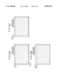
- the image (hatched portion) shown in FIG. 6A that is intended in the original setting of the machine is deviated (by, for example, the amounts ⁇ and ⁇ in the x and y directions, respectively) in practice as shown in FIG. 6B or FIG. 6C with no margin left on one side or even the image partly falling outside the copy sheet.
- Such a trend is more pronounced in a large machine or when the distance from the cassette to the registration rollers is longer.
- It is yet a further object of the present invention to provide an image forming apparatus that comprises image forming means for forming an image at a proper position on the recording material, correct means for correcting skew of the recording material advancing to an image forming position, detector means for detecting the position of the recording material that is underway from the position of the correct means to the image forming position, and control means for controlling the image forming means in accordance with the output of the detector means.
- FIG. 1 is a cross-sectional view showing a first embodiment of image forming apparatus of the present invention
- FIG. 2 diagrammatically illustrates an image forming position on a copy sheet in the first embodiment of the image forming apparatus of the present invention shown FIG. 1;
- FIG. 3 is illustrates an emission timing of laser in the first embodiment of the image forming apparatus of the present invention shown in FIG. 1;
- FIG. 4 is a cross-sectional view showing a second embodiment of image forming apparatus of the present invention.
- FIG. 5 is a cross-sectional view showing a conventional image forming apparatus.
- FIG. 6 diagrammatically illustrates an image forming position on a copy sheet in the conventional image forming apparatus.
- the present invention is implemented in a full-color copying machine.
- the present invention is implemented in a full-color machine for the convenience of discussion of a plurality of functions of the present invention and it is not intended to limit the present invention to the full-color copying machine.
- FIG. 1 is a cross-sectional view of a full-color copying machine.
- a copy sheet (paper) as a recording material is supplied by cassette 1a or 1b or manual-feeding unit 1c.
- the copy sheet stays in contact with a registration roller 2 to wait for the timing of an image forming section and to correct its skew as well.
- the original document is transported to a document carriage platen 3, and is scanned by an optical system 4.
- the image of the original document is thus read by a CCD, and is separated into a yellow image (Y), magenta image (M), cyan image (C) and black image (Bk).
- the registration rollers 2 are then rotated and a linear sensor 50 as sensor means for paper edge detector means detects the accurate position of the copy sheet on a transfer belt 11 as recording material transport means.
- the copy sheet is attracted to the transfer belt 11 by static charge and is transferred along with the transfer belt 11, without slipping off the transfer belt 11.
- means such as an attracting roller may be employed.
- an image forming light projection section 5 flashes laser beams for Y, M, C and Bk components in accordance with image information at image forming positions and projects sequentially respectively the Y, M, C and Bk laser beams to photoconductive drums 6Y, 6M, 6C and 6Bk, as image bearing media, all of which are already uniformly pre-charged by primary charging units 7Y, 7M, 7C and 7Bk, respectively, to form latent images.
- Development units 8Y, 8M, 8C and 8Bk apply toner to the respective latent images for development, and transfer charging units 9Y, 9M, 9C and 9Bk transfer the respective resulting toner images to the copy sheet that is being transported by the transfer belt 11.
- cleaning units 10Y, 10M, 10C and 10Bk which remove toner residues on the respective photoconductive drums 6Y, 6M, 6C and 6Bk for cleaning after transfer. In this way the toner images on the respective photoconductive drums are transferred to the copy sheet on the transfer belt 11 at the image forming positions so that image forming is sequentially performed color by color on the same copy sheet.
- the copy sheet is then sent to a fixing unit 12, where the toner images are thermally fused for fixing.
- the copy sheet is then delivered out of the apparatus and stacked into a tray 20.
- a flapper 13 arranged in front of a both-side copying transport path guides the copy sheet S to an turnaround section 14, where the copy sheet S is turned around, and is transported via the path 15 and then placed on an intermediate tray 16.
- a re-feed section 17 re-feeds the copy sheet to subject the bottom side of the copy sheet to image forming process and is then stacked into the tray 20 outside the apparatus body.
- the use of the manual-feeding unit permits the full-color copying machine of the present invention to transport a diversity of copy sheets.
- the copy sheets may be thin sheets, thick sheets, film sheets such as OHP film, and Japanese paper sheets, and even cloth. Such a diversity of sheets abut the registration roller 2 in different ways, and their top margins are accordingly varied.
- the linear sensor 50 is thus arranged to detect the forward edge of the copy sheet upstream of a transfer process (in the image forming position) as shown in FIG. 2.
- a CCD sensor covers entirely the width of the copy sheet as shown in FIG. 2.
- the sensor is arranged to cover one lateral side portion only when the sheets are aligned to one side.
- the linear sensor 50 detects the forward edge and left and right side edges (200). Based on these data, the image forming timings by the laser onto the photoconductive drum is determined in the direction of paper advance and in the direction perpendicular to the direction of paper advance (201). The timing information is fed back to a laser driver (202) to form an image on the photoconductive drum.
- the emission of laser beam is timed in consideration of four factors, namely the transport speed of the transfer belt, the distance between the position of the linear sensor 50 and transfer position, and the distance from the exposure position to transfer position on the photoconductive drum, and the circumferential speed of the photoconductive drum.
- the left and right side margins y are determined by the timing of image forming by the laser on the photoconductive drum as shown in FIG. 3.
- the emission of the laser is started l seconds after detecting the laser with a BD (beam detect) sensor in a laser scanner.
- the value l is adjusted by changing the timing of laser emission in accordance with the position of the sheet detected by the linear sensor 50, and the left and right side margins are thus determined.
- the image forming timing is determined solely depending on the on timing of the registration roller 2.
- the forward edge of the copy sheet on the transfer belt 11 underway to the transfer position for the actual image transfer is detected upstream of the transfer position, and image forming is performed based on the detected signal. The image forming position is thus accurately adjusted.
- Accurate adjustment of the image forming position is particularly important in both-side printing operation when copy sheets are later bound into a book. If no accurate alignment is assured between images on the top side and bottom side of each copy sheet, subsequent cutting of the copy sheets may partly cut away the images.
- the present invention precludes such a problem.
- the laser is used as image forming means for forming images on the photoconductive drum.
- exposure means such as LEDs and liquid-crystal shutters may be used.
- the photoconductive drum as the photoconductive body is used in the above embodiment.
- a photoconductive belt may be used.
- FIG. 4 shows a second embodiment of the present invention.
- the transfer belt is used as the recording material transport means while a transfer drum is used as the recording material transport means in the second embodiment.
- the rest of the construction of the second embodiment remains unchanged from that of the first embodiment.
- Like reference numerals are employed to designate like elements.
- FIG. 4 is a cross-sectional view of a full-color copying machine that uses the transfer drum.
- a latent image is formed on the photoconductive drum 6 by a laser and is then subjected to the development step at each of development units.
- the copy sheet as the recording material is supplied from the cassette 1a, 1b or the manual-feeding unit 1c, and is corrected in skew by the registration roller 2.
- the copy sheet then advances to the transfer drum 18 which electrostatically attracts it through attracting means. Images sequentially developed on the photoconductive drum 6 are transferred to the copy sheet by the transfer charging unit 9 charged up by a high tension voltage while the transfer drum 18 rotates in the direction of the arrow shown. This process is repeated four times to superimpose four colors of yellow, magenta, cyan and black on the recording material.
- the copy sheet is then detached from the transfer drum, and is introduced into the fixing unit 12 where the images are thermally fused for fixing.
- the copy sheet is then delivered out of the apparatus body into the tray 20.
- a linear sensor 50 for detecting an edge of the recording material on the transfer drum 18 is arranged between the registration roller 2 and the transfer position.
- the timing of the latent image forming on the photoconductive drum 6 is controlled based on the detected signal in the same way as the first embodiment. The image forming position to the copy sheet is thus accurately determined.
Landscapes
- Engineering & Computer Science (AREA)
- Multimedia (AREA)
- Signal Processing (AREA)
- Microelectronics & Electronic Packaging (AREA)
- Physics & Mathematics (AREA)
- General Physics & Mathematics (AREA)
- Control Or Security For Electrophotography (AREA)
- Paper Feeding For Electrophotography (AREA)
- Registering Or Overturning Sheets (AREA)
Abstract
An image forming apparatus for forming an image on a recording material. The position of the recording material is detected when the recording material is underway from a registration roller for correcting a skew of the recording material to an image forming position for the recording material, and the image is written based on the detected position signal. The image is thus formed at a proper position on the recording material.
Description
1. Field of the Invention
The present invention relates to an image forming apparatus such as a copying machine and a printer.
2. Description of the Related Art
One type of image forming apparatuses available is an electrophotographic machine in which an image light beam bearing image information of an original document is directed to a photoconductive drum to form a latent image thereon, a development unit applies toner to the photoconductive drum to develop a toner image thereon, the toner image is then transferred to a copy sheet as a recording material, and the copy sheet is passed through a fixing unit which thermally fuses the toner to fix the image onto the copy sheet.
FIG. 5 shows a full-color copying machine, for example, and the transportation of a copy sheet is now briefly discussed.
A copy sheet is fed from cassette C1 or C2 or a manual-feeding unit C3. When the forward edge of the copy sheet abuts registration rollers 101, the correction of skew of the copy sheet is performed.
The registration rollers 101 start rotating in synchronization with image write timing on the photoconductive drum. The registration rollers 101 transport the copy sheet to a transfer belt 102, which in turn transports the copy sheet to an image developing unit.
As shown in FIG. 6A, the on timing of the registration rollers 101 is set such that an image to be formed is aligned at the center of the copy sheet with a predetermined margin (top margin) x permitted in the direction of paper advance.
(Left and right) side margins y with respect to the direction of advance are set by fine-adjusting, in the direction of main scan, emission timing of an image forming laser beam that is projected to the photoconductive drum, after the positions of the cassettes C1 and C2 and the manual-feeding unit C3 are adjusted relative to the photoconductive drum in alignment.
In the conventional art, the adjustment of the top margin x and side margins y is usually performed during manufacturing steps in a plant or performed in the field by service engineers and is not the responsibility of users.
The top margin x and side margins y are thus determined by the initial setting of the machine including the on timing of the registration roller. The skew (oblique running) of the copy sheet is corrected when the forward edge of the copy sheet abuts the registration roller. However, there are times when the copy sheet shifts laterally in a direction (y direction in FIG. 6) perpendicular to the direction of paper advance in the course of skew correction.
Japanese Patents Laid-Open No. 8-95432 and No. 8-305098 disclose the techniques that shift the image write position on the photoconductive drum according to the lateral shift of the copy sheet in the y direction.
The inventors of this invention have learned that the forward margin x varies when the forward edge of copy sheet is introduced into the nib of the registration rollers differently depending on the type of copy sheets (for example, thickness and strength), when an error takes place in the transport speed of copy sheet, or when the on timing of the registration rollers varies depending on errors in gear meshing and clutch response time even if the same type of copy sheets are used.
For these variations, the image (hatched portion) shown in FIG. 6A that is intended in the original setting of the machine is deviated (by, for example, the amounts α and β in the x and y directions, respectively) in practice as shown in FIG. 6B or FIG. 6C with no margin left on one side or even the image partly falling outside the copy sheet. Such a trend is more pronounced in a large machine or when the distance from the cassette to the registration rollers is longer.
There is a growing demand that the image forming apparatuses including copying machines work with relatively large sheet sizes besides widely used standard sheet sizes such as sheet sizes A and B. For example, large size sheets, such as the ones used in the printing industry, are printed and then cut into A and B sheet sizes. Although higher accuracy is required of the image forming apparatus in image forming position on a copy sheet in such an application, the conventional art fails to meet such accuracy requirement.
Accordingly, it is one object of the present invention to provide an image forming apparatus that forms an image at a proper position on a recording material.
It is yet another object of the present invention to provide an image forming apparatus that forms an image at a proper position on a recording material by detecting a deviation of the recording material in the direction of advance.
It is yet a further object of the present invention to provide an image forming apparatus that forms an image at a proper position on a recording material by detecting a deviation of the recording material in the direction perpendicular to the direction of advance.
It is yet a further object of the present invention to provide an image forming apparatus that comprises image forming means for forming an image at a proper position on the recording material, correct means for correcting skew of the recording material advancing to an image forming position, detector means for detecting the position of the recording material that is underway from the position of the correct means to the image forming position, and control means for controlling the image forming means in accordance with the output of the detector means.
These and other objects and advantages of the present invention will become apparent from the following description, the accompanying drawings and the appended claims.
FIG. 1 is a cross-sectional view showing a first embodiment of image forming apparatus of the present invention;
FIG. 2 diagrammatically illustrates an image forming position on a copy sheet in the first embodiment of the image forming apparatus of the present invention shown FIG. 1;
FIG. 3 is illustrates an emission timing of laser in the first embodiment of the image forming apparatus of the present invention shown in FIG. 1;
FIG. 4 is a cross-sectional view showing a second embodiment of image forming apparatus of the present invention;
FIG. 5 is a cross-sectional view showing a conventional image forming apparatus; and
FIG. 6 diagrammatically illustrates an image forming position on a copy sheet in the conventional image forming apparatus.
Referring now to the drawings, the embodiments of the present invention are discussed. It is understood that the scope of the present invention is not limited to the dimensions, materials, shapes and relative positions of the elements to be described in the embodiments unless otherwise specifically described.
First Embodiment
The image forming apparatus of a first embodiment of the present invention is now discussed. In the first embodiment, the present invention is implemented in a full-color copying machine. The present invention is implemented in a full-color machine for the convenience of discussion of a plurality of functions of the present invention and it is not intended to limit the present invention to the full-color copying machine.
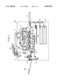
FIG. 1 is a cross-sectional view of a full-color copying machine.
First, the apparatus body 30 of the full-color machine is briefly discussed.
A user presses a start button (not shown) with an original document (not shown) placed on the automatic document feeder DF. A copy sheet (paper) as a recording material is supplied by cassette 1a or 1b or manual-feeding unit 1c. The copy sheet stays in contact with a registration roller 2 to wait for the timing of an image forming section and to correct its skew as well. Meanwhile, the original document is transported to a document carriage platen 3, and is scanned by an optical system 4. The image of the original document is thus read by a CCD, and is separated into a yellow image (Y), magenta image (M), cyan image (C) and black image (Bk).
The registration rollers 2 are then rotated and a linear sensor 50 as sensor means for paper edge detector means detects the accurate position of the copy sheet on a transfer belt 11 as recording material transport means. The copy sheet is attracted to the transfer belt 11 by static charge and is transferred along with the transfer belt 11, without slipping off the transfer belt 11. To assist the transfer belt 11 to attract the copy sheet, means such as an attracting roller may be employed.
With the linear sensor 50 detecting the position of the copy sheet, an image forming light projection section 5 flashes laser beams for Y, M, C and Bk components in accordance with image information at image forming positions and projects sequentially respectively the Y, M, C and Bk laser beams to photoconductive drums 6Y, 6M, 6C and 6Bk, as image bearing media, all of which are already uniformly pre-charged by primary charging units 7Y, 7M, 7C and 7Bk, respectively, to form latent images.
Development units 8Y, 8M, 8C and 8Bk apply toner to the respective latent images for development, and transfer charging units 9Y, 9M, 9C and 9Bk transfer the respective resulting toner images to the copy sheet that is being transported by the transfer belt 11. Also provided are cleaning units 10Y, 10M, 10C and 10Bk which remove toner residues on the respective photoconductive drums 6Y, 6M, 6C and 6Bk for cleaning after transfer. In this way the toner images on the respective photoconductive drums are transferred to the copy sheet on the transfer belt 11 at the image forming positions so that image forming is sequentially performed color by color on the same copy sheet.
The copy sheet is then sent to a fixing unit 12, where the toner images are thermally fused for fixing. The copy sheet is then delivered out of the apparatus and stacked into a tray 20.
To form images on both sides of the copy sheet, a flapper 13 arranged in front of a both-side copying transport path guides the copy sheet S to an turnaround section 14, where the copy sheet S is turned around, and is transported via the path 15 and then placed on an intermediate tray 16. After the original document is replaced, a re-feed section 17 re-feeds the copy sheet to subject the bottom side of the copy sheet to image forming process and is then stacked into the tray 20 outside the apparatus body.
Accuracy improvements in image forming position in the image forming apparatus of the first embodiment are now discussed referring to FIG. 2.
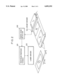
As shown, three sheets, designated A, B and C, are now placed on the transfer belt. Each sheet had been corrected in skew by the registration roller before it was sent to the transfer belt 11. The positions of the copy sheets on the transfer belt 11, namely thrust positions relative to the photoconductor drums (in the direction perpendicular to the direction of advance of sheets), are subject to slight variations, after the registration roller 2 corrected skew of each sheet. The degree of variations is more pronounced as the distance between the sheet feeding position of sheets and the registration roller 2 is larger. Furthermore, the degree of variations is more pronounced when the copy sheet is not reliably restrained by lateral restraint means (not shown) arranged in the cassette or when the copy sheets are not uniform.
The use of the manual-feeding unit permits the full-color copying machine of the present invention to transport a diversity of copy sheets. The copy sheets may be thin sheets, thick sheets, film sheets such as OHP film, and Japanese paper sheets, and even cloth. Such a diversity of sheets abut the registration roller 2 in different ways, and their top margins are accordingly varied.
Even copy sheets of the same type suffer position variations because the on timing of the registration rollers is affected by gear meshing and response time of a clutch.
The deviation of the image forming positions of the copy sheet in the direction of advance and the direction perpendicular to the direction of advance must be precluded. The linear sensor 50 is thus arranged to detect the forward edge of the copy sheet upstream of a transfer process (in the image forming position) as shown in FIG. 2. In this embodiment, a CCD sensor covers entirely the width of the copy sheet as shown in FIG. 2. Alternatively, the sensor is arranged to cover one lateral side portion only when the sheets are aligned to one side.
The linear sensor 50 detects the forward edge and left and right side edges (200). Based on these data, the image forming timings by the laser onto the photoconductive drum is determined in the direction of paper advance and in the direction perpendicular to the direction of paper advance (201). The timing information is fed back to a laser driver (202) to form an image on the photoconductive drum.
To keep constant the forward margin x in FIG. 2, the emission of laser beam is timed in consideration of four factors, namely the transport speed of the transfer belt, the distance between the position of the linear sensor 50 and transfer position, and the distance from the exposure position to transfer position on the photoconductive drum, and the circumferential speed of the photoconductive drum.
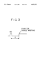
The left and right side margins y are determined by the timing of image forming by the laser on the photoconductive drum as shown in FIG. 3.
The emission of the laser is started l seconds after detecting the laser with a BD (beam detect) sensor in a laser scanner. The value l is adjusted by changing the timing of laser emission in accordance with the position of the sheet detected by the linear sensor 50, and the left and right side margins are thus determined.
In the conventional art, the image forming timing is determined solely depending on the on timing of the registration roller 2. In this embodiment, the forward edge of the copy sheet on the transfer belt 11 underway to the transfer position for the actual image transfer is detected upstream of the transfer position, and image forming is performed based on the detected signal. The image forming position is thus accurately adjusted.
Accurate adjustment of the image forming position is particularly important in both-side printing operation when copy sheets are later bound into a book. If no accurate alignment is assured between images on the top side and bottom side of each copy sheet, subsequent cutting of the copy sheets may partly cut away the images. The present invention precludes such a problem.
This embodiment has been discussed in connection with the full-color copying machine. The present invention is not only implemented in the full-color copying machine but also in image forming apparatuses including black-white copying machines, printers and facsimile machines
The laser is used as image forming means for forming images on the photoconductive drum. Alternatively, exposure means such as LEDs and liquid-crystal shutters may be used.
The photoconductive drum as the photoconductive body is used in the above embodiment. Alternatively, a photoconductive belt may be used.
Second Embodiment
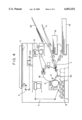
FIG. 4 shows a second embodiment of the present invention. In the first embodiment, the transfer belt is used as the recording material transport means while a transfer drum is used as the recording material transport means in the second embodiment. The rest of the construction of the second embodiment remains unchanged from that of the first embodiment. Like reference numerals are employed to designate like elements.
FIG. 4 is a cross-sectional view of a full-color copying machine that uses the transfer drum.
Since the image forming process used herein is the known one, no detailed explanation is given. A latent image is formed on the photoconductive drum 6 by a laser and is then subjected to the development step at each of development units.
The copy sheet as the recording material is supplied from the cassette 1a, 1b or the manual-feeding unit 1c, and is corrected in skew by the registration roller 2. The copy sheet then advances to the transfer drum 18 which electrostatically attracts it through attracting means. Images sequentially developed on the photoconductive drum 6 are transferred to the copy sheet by the transfer charging unit 9 charged up by a high tension voltage while the transfer drum 18 rotates in the direction of the arrow shown. This process is repeated four times to superimpose four colors of yellow, magenta, cyan and black on the recording material. The copy sheet is then detached from the transfer drum, and is introduced into the fixing unit 12 where the images are thermally fused for fixing. The copy sheet is then delivered out of the apparatus body into the tray 20.
The general image forming process has been described. In the second embodiment, a linear sensor 50 for detecting an edge of the recording material on the transfer drum 18 is arranged between the registration roller 2 and the transfer position. The timing of the latent image forming on the photoconductive drum 6 is controlled based on the detected signal in the same way as the first embodiment. The image forming position to the copy sheet is thus accurately determined.
The present invention is not limited to the above embodiments and allows changes and modifications without departing from the spirit and scope of the present invention.
Claims (19)
1. An image forming apparatus for forming an image on a recording material, comprising:
image forming means for forming the image on the recording material at an image forming position;
correct means for correcting a skew of the recording material that moves toward the image forming position;
detector means located downstream of said correct means in a direction of advance of the recording material for detecting a position of at least one side edge of the recording material that moves from the position of said correct means to the image forming position; and
control means for controlling said image forming means in accordance with an output of said detector means.
2. An image forming apparatus according to claim 1, wherein said detector means further detects a position of a leading edge of the recording material.
3. An image forming apparatus according to claim 2, wherein said image forming means comprises an image bearing member and image write means for writing the image onto said image bearing member, and wherein said control means controls the timing of the image writing by said write means in accordance with the output of said detector means.
4. An image forming apparatus according to claim 3, wherein said control means controls the writing timing to correct the position of the image on the recording material in the direction of advance of the recording material.
5. An image forming apparatus according to claim 3, wherein said control means controls the writing timing to correct the position of the image on the recording material in the direction perpendicular to the direction of advance of the recording material.
6. An image forming apparatus according to claim 1, wherein said detector means is a linear sensor that is extended perpendicular to the direction of advance of the recording material.
7. An image forming apparatus according to claim 6, wherein said linear sensor is a charge coupled device.
8. An image forming apparatus according to claim 1, wherein said correct means comprises a registration roller.
9. An image forming apparatus according to claim 1, further comprising a transfer conveyor, located downstream of said correct means, for transporting the recording material through the image forming position, wherein said detector means is positioned to detect the recording material as the recording material is being transported by said transfer conveyor.
10. An image forming apparatus according to claim 9, wherein said transfer conveyor is one of a transfer belt and a transfer drum.
11. An image forming apparatus for forming an image on a recording material, comprising:
image forming means for forming the image on the recording material at an image forming position;
a recording material conveyer for conveying the recording material to the image forming position, wherein said conveyer holds and moves together with the recording material;
detector means for detecting a position of the recording material held on said conveyer; and
control means for controlling said image forming means in accordance with an output of said detector means.
12. An image forming apparatus according to claim 11, wherein said detector means detects a position of at least one side edge of the recording material.
13. An image forming apparatus according to claim 11, wherein said detector means detects a position of a leading edge of the recording material.
14. An image forming apparatus according to claim 11, wherein said image forming means comprises an image bearing member and image write means for writing the image onto said image bearing member, and wherein said control means controls a timing of an image writing by said write means in accordance with the output of said detector means.
15. An image forming apparatus according to claim 11, further comprising a correct means for correcting a skew of the recording material moving toward the image forming position, and
wherein said detector means is located downstream of said correct means in a direction of advance of the recording material.
16. An image forming apparatus according to claim 15, wherein said correct means comprises a registration roller.
17. An image forming apparatus according to claim 11, wherein said conveyer holds the recording material electrostatically.
18. An image forming apparatus according to claim 11, wherein said detector means comprises a linear sensor that is extended perpendicular to the direction of advance of the recording material.
19. An image forming apparatus according to claim 18, wherein said linear sensor comprises a charge coupled device.
Applications Claiming Priority (2)
| Application Number | Priority Date | Filing Date | Title |
|---|---|---|---|
| JP8-356945 | 1996-12-26 | ||
| JP8356945A JPH10186951A (en) | 1996-12-26 | 1996-12-26 | Image forming device |
Publications (1)
| Publication Number | Publication Date |
|---|---|
| US6052552A true US6052552A (en) | 2000-04-18 |
Family
ID=18451573
Family Applications (1)
| Application Number | Title | Priority Date | Filing Date |
|---|---|---|---|
| US08/995,908 Expired - Lifetime US6052552A (en) | 1996-12-26 | 1997-12-22 | Image forming apparatus with skew correction |
Country Status (2)
| Country | Link |
|---|---|
| US (1) | US6052552A (en) |
| JP (1) | JPH10186951A (en) |
Cited By (17)
| Publication number | Priority date | Publication date | Assignee | Title |
|---|---|---|---|---|
| US6342909B1 (en) * | 1999-03-23 | 2002-01-29 | Konica Corporation | Method and apparatus for image formation while considering a position of a transfer sheet in a primary scanning direction |
| US20020181021A1 (en) * | 2001-05-30 | 2002-12-05 | Stephens Vance M. | Techniques for aligning images using page characteristics and image shifting |
| US6532873B2 (en) * | 2000-05-17 | 2003-03-18 | Nexpress Solutions Llc | Method and apparatus for setting registration in a printing machine |
| US6588869B1 (en) * | 1998-11-05 | 2003-07-08 | Gateway, Inc. | Front accessible, stackable, printer/scanner/fax |
| WO2003067339A1 (en) * | 2002-02-06 | 2003-08-14 | Canon Kabushiki Kaisha | Image forming apparatus and image formation control method |
| US6799761B2 (en) * | 2000-03-15 | 2004-10-05 | Canon Kabushiki Kaisha | Sheet-position detection device and image forming apparatus including the same |
| DE10214106B4 (en) * | 2001-04-02 | 2005-11-10 | Hewlett-Packard Development Co., L.P., Houston | Method and device for detecting overhead transparencies |
| US20060087548A1 (en) * | 2004-10-21 | 2006-04-27 | Samsung Electronics Co., Ltd. | Image forming apparatus and an image forming method using the same |
| US20060087664A1 (en) * | 2004-10-27 | 2006-04-27 | Pozuelo Francisco J | Inter-device media handler |
| US20060177254A1 (en) * | 2005-02-09 | 2006-08-10 | Olympus Corporation | Image recording apparatus and image recording method |
| US20070053727A1 (en) * | 2005-09-02 | 2007-03-08 | Canon Kabushiki Kaisha | Image forming apparatus and method of controlling the same |
| US20070201922A1 (en) * | 2006-02-24 | 2007-08-30 | Canon Kabushiki Kaisha | Image forming apparatus and control method |
| US20080253785A1 (en) * | 2007-04-10 | 2008-10-16 | Canon Kabushiki Kaisha | Image forming apparatus and image forming method |
| US7898695B1 (en) | 2000-10-06 | 2011-03-01 | Lexmark International, Inc. | Method of compensating for electronic printhead skew and bow correction in an imaging machine to reduce print artifacts |
| US20120141179A1 (en) * | 2010-12-03 | 2012-06-07 | Sharp Kabushiki Kaisha | Image forming apparatus |
| US8608273B2 (en) | 2011-03-02 | 2013-12-17 | Ricoh Production Print Solutions | Print data compensation for variations in paper position within a printing system |
| US11409220B2 (en) | 2019-07-11 | 2022-08-09 | Hewlett-Packard Development Company, L.P. | Print indicia for skew correction |
Families Citing this family (3)
| Publication number | Priority date | Publication date | Assignee | Title |
|---|---|---|---|---|
| JPH11237768A (en) * | 1998-02-23 | 1999-08-31 | Ricoh Co Ltd | Recorder |
| WO2004099883A1 (en) | 2003-05-08 | 2004-11-18 | Sharp Kabushiki Kaisha | Image forming device |
| JP3831373B2 (en) * | 2003-10-31 | 2006-10-11 | シャープ株式会社 | Sheet detecting apparatus and image forming apparatus |
Citations (8)
| Publication number | Priority date | Publication date | Assignee | Title |
|---|---|---|---|---|
| US4755855A (en) * | 1985-05-30 | 1988-07-05 | Kabushiki Kaisha Toshiba | Image forming apparatus with a forming position correcting function |
| US4814792A (en) * | 1987-03-25 | 1989-03-21 | Ricoh Company, Ltd. | Lateral registration adjusting device for use in a laser beam printer |
| US4914485A (en) * | 1987-08-28 | 1990-04-03 | Minolta Camera Kabushiki Kaisha | Image forming apparatus |
| US5093674A (en) * | 1990-08-02 | 1992-03-03 | Hewlett-Packard Company | Method and system for compensating for paper shrinkage and misalignment in electrophotographic color printing |
| US5134427A (en) * | 1989-09-08 | 1992-07-28 | Canon Kabushiki Kaisha | Image forming apparatus |
| JPH0895432A (en) * | 1994-09-26 | 1996-04-12 | Canon Inc | Image forming device |
| JPH08305098A (en) * | 1995-04-28 | 1996-11-22 | Canon Inc | Image forming device |
| US5600421A (en) * | 1993-09-17 | 1997-02-04 | Canon Kabushiki Kaisha | Image forming apparatus |
-
1996
- 1996-12-26 JP JP8356945A patent/JPH10186951A/en active Pending
-
1997
- 1997-12-22 US US08/995,908 patent/US6052552A/en not_active Expired - Lifetime
Patent Citations (8)
| Publication number | Priority date | Publication date | Assignee | Title |
|---|---|---|---|---|
| US4755855A (en) * | 1985-05-30 | 1988-07-05 | Kabushiki Kaisha Toshiba | Image forming apparatus with a forming position correcting function |
| US4814792A (en) * | 1987-03-25 | 1989-03-21 | Ricoh Company, Ltd. | Lateral registration adjusting device for use in a laser beam printer |
| US4914485A (en) * | 1987-08-28 | 1990-04-03 | Minolta Camera Kabushiki Kaisha | Image forming apparatus |
| US5134427A (en) * | 1989-09-08 | 1992-07-28 | Canon Kabushiki Kaisha | Image forming apparatus |
| US5093674A (en) * | 1990-08-02 | 1992-03-03 | Hewlett-Packard Company | Method and system for compensating for paper shrinkage and misalignment in electrophotographic color printing |
| US5600421A (en) * | 1993-09-17 | 1997-02-04 | Canon Kabushiki Kaisha | Image forming apparatus |
| JPH0895432A (en) * | 1994-09-26 | 1996-04-12 | Canon Inc | Image forming device |
| JPH08305098A (en) * | 1995-04-28 | 1996-11-22 | Canon Inc | Image forming device |
Cited By (30)
| Publication number | Priority date | Publication date | Assignee | Title |
|---|---|---|---|---|
| US6588869B1 (en) * | 1998-11-05 | 2003-07-08 | Gateway, Inc. | Front accessible, stackable, printer/scanner/fax |
| EP1039739A3 (en) * | 1999-03-23 | 2002-10-23 | Konica Corporation | Writing control method and image forming apparatus. |
| US6342909B1 (en) * | 1999-03-23 | 2002-01-29 | Konica Corporation | Method and apparatus for image formation while considering a position of a transfer sheet in a primary scanning direction |
| US6799761B2 (en) * | 2000-03-15 | 2004-10-05 | Canon Kabushiki Kaisha | Sheet-position detection device and image forming apparatus including the same |
| US6532873B2 (en) * | 2000-05-17 | 2003-03-18 | Nexpress Solutions Llc | Method and apparatus for setting registration in a printing machine |
| US7898695B1 (en) | 2000-10-06 | 2011-03-01 | Lexmark International, Inc. | Method of compensating for electronic printhead skew and bow correction in an imaging machine to reduce print artifacts |
| DE10214106B4 (en) * | 2001-04-02 | 2005-11-10 | Hewlett-Packard Development Co., L.P., Houston | Method and device for detecting overhead transparencies |
| US20020181021A1 (en) * | 2001-05-30 | 2002-12-05 | Stephens Vance M. | Techniques for aligning images using page characteristics and image shifting |
| US7456995B2 (en) * | 2001-05-30 | 2008-11-25 | Hewlett-Packard Development Company, L.P. | Techniques for aligning images using page characteristics and image shifting |
| US6934504B2 (en) | 2002-02-06 | 2005-08-23 | Canon Kabushiki Kaisha | Image forming apparatus and image formation control method |
| US20050214049A1 (en) * | 2002-02-06 | 2005-09-29 | Canon Kabushiki Kaisha | Image forming apparatus and image formation control method |
| US7016642B2 (en) | 2002-02-06 | 2006-03-21 | Canon Kabushiki Kaisha | Image forming apparatus and image formation control method |
| US20050002712A1 (en) * | 2002-02-06 | 2005-01-06 | Canon Kabushiki Kaisha | Image forming apparatus and image formation control method |
| WO2003067339A1 (en) * | 2002-02-06 | 2003-08-14 | Canon Kabushiki Kaisha | Image forming apparatus and image formation control method |
| CN100368939C (en) * | 2002-02-06 | 2008-02-13 | 佳能株式会社 | Image forming apparatus and image formation control method |
| US20060087548A1 (en) * | 2004-10-21 | 2006-04-27 | Samsung Electronics Co., Ltd. | Image forming apparatus and an image forming method using the same |
| US20060087664A1 (en) * | 2004-10-27 | 2006-04-27 | Pozuelo Francisco J | Inter-device media handler |
| US7643161B2 (en) * | 2004-10-27 | 2010-01-05 | Hewlett-Packard Development Company, L.P. | Inter-device media handler |
| US20060177254A1 (en) * | 2005-02-09 | 2006-08-10 | Olympus Corporation | Image recording apparatus and image recording method |
| US7499654B2 (en) * | 2005-02-09 | 2009-03-03 | Olympus Corporation | Image recording apparatus and image recording method |
| US7509082B2 (en) * | 2005-09-02 | 2009-03-24 | Canon Kabushiki Kaisha | Image forming apparatus and method of controlling the same |
| US20070053727A1 (en) * | 2005-09-02 | 2007-03-08 | Canon Kabushiki Kaisha | Image forming apparatus and method of controlling the same |
| US20070201922A1 (en) * | 2006-02-24 | 2007-08-30 | Canon Kabushiki Kaisha | Image forming apparatus and control method |
| US8447202B2 (en) | 2006-02-24 | 2013-05-21 | Canon Kabushiki Kaisha | Printing without margins-enabled image forming apparatus and control method |
| US20080253785A1 (en) * | 2007-04-10 | 2008-10-16 | Canon Kabushiki Kaisha | Image forming apparatus and image forming method |
| US8204427B2 (en) * | 2007-04-10 | 2012-06-19 | Canon Kabushiki Kaisha | Image forming apparatus with multiple lateral alignment positions |
| US20120141179A1 (en) * | 2010-12-03 | 2012-06-07 | Sharp Kabushiki Kaisha | Image forming apparatus |
| US8988726B2 (en) * | 2010-12-03 | 2015-03-24 | Sharp Kabushiki Kaisha | Image forming apparatus capable of correcting trasport position displacement of recording sheet |
| US8608273B2 (en) | 2011-03-02 | 2013-12-17 | Ricoh Production Print Solutions | Print data compensation for variations in paper position within a printing system |
| US11409220B2 (en) | 2019-07-11 | 2022-08-09 | Hewlett-Packard Development Company, L.P. | Print indicia for skew correction |
Also Published As
| Publication number | Publication date |
|---|---|
| JPH10186951A (en) | 1998-07-14 |
Similar Documents
| Publication | Publication Date | Title |
|---|---|---|
| US6052552A (en) | Image forming apparatus with skew correction | |
| US10114327B2 (en) | Image forming apparatus | |
| JP5039296B2 (en) | Image forming apparatus | |
| US6345171B1 (en) | Image forming apparatus and a method to control paper conveying speeds in image forming apparatus | |
| JP4422250B2 (en) | Image forming apparatus | |
| JP5072238B2 (en) | Image forming apparatus | |
| US20190129345A1 (en) | Image forming apparatus and conveyance control method | |
| JP2007047555A (en) | Image forming apparatus | |
| JP5673240B2 (en) | Image forming apparatus | |
| JP4717723B2 (en) | Recording material detector | |
| US10737894B2 (en) | Image forming apparatus and conveyance control method | |
| JP3882533B2 (en) | Paper conveying apparatus and image forming apparatus | |
| JPH10329984A (en) | Sheet discriminating system and image forming device | |
| JP2002338084A (en) | Image forming device | |
| JP3918463B2 (en) | Paper conveying apparatus and image forming apparatus | |
| JP2003035974A (en) | Image forming device | |
| JP7399384B2 (en) | Sheet loading device, sheet feeding device, and image forming device | |
| JP2003280485A (en) | Image recording device | |
| JP2018090416A (en) | Image formation apparatus | |
| US11952239B2 (en) | Sheet feeding device and image forming apparatus | |
| US20240255888A1 (en) | Image forming apparatus | |
| US20230312293A1 (en) | Medium transport device and image forming apparatus | |
| JP2002316748A (en) | Paper feeder and image forming device | |
| US20230312288A1 (en) | Medium transport device and image forming apparatus | |
| JP2006071922A (en) | Image forming apparatus and misregistration correcting method |
Legal Events
| Date | Code | Title | Description |
|---|---|---|---|
| AS | Assignment |
Owner name: CANON KABUSHIKI KAISHA, JAPAN Free format text: ASSIGNMENT OF ASSIGNORS INTEREST;ASSIGNORS:OHSUMI, KIYOTAKA;OHNO, AKIO;REEL/FRAME:009195/0174;SIGNING DATES FROM 19980413 TO 19980416 |
|
| STCF | Information on status: patent grant |
Free format text: PATENTED CASE |
|
| CC | Certificate of correction | ||
| FEPP | Fee payment procedure |
Free format text: PAYOR NUMBER ASSIGNED (ORIGINAL EVENT CODE: ASPN); ENTITY STATUS OF PATENT OWNER: LARGE ENTITY |
|
| FPAY | Fee payment |
Year of fee payment: 4 |
|
| FPAY | Fee payment |
Year of fee payment: 8 |
|
| FPAY | Fee payment |
Year of fee payment: 12 |