JP2005255308A - Warpage correction device for recording paper and image forming device using it - Google Patents
Warpage correction device for recording paper and image forming device using it Download PDFInfo
- Publication number
- JP2005255308A JP2005255308A JP2004067461A JP2004067461A JP2005255308A JP 2005255308 A JP2005255308 A JP 2005255308A JP 2004067461 A JP2004067461 A JP 2004067461A JP 2004067461 A JP2004067461 A JP 2004067461A JP 2005255308 A JP2005255308 A JP 2005255308A
- Authority
- JP
- Japan
- Prior art keywords
- recording paper
- roller
- warp
- recording
- paper
- Prior art date
- Legal status (The legal status is an assumption and is not a legal conclusion. Google has not performed a legal analysis and makes no representation as to the accuracy of the status listed.)
- Pending
Links
Images


Abstract
Description
本発明は、電子写真方式あるいは静電記録方式等の画像形成装置に用いられる記録用紙の反り矯正装置、及びそれを用いた画像形成装置に関する。 The present invention relates to a warp correction device for a recording sheet used in an image forming apparatus such as an electrophotographic system or an electrostatic recording system, and an image forming apparatus using the same.
周知の様に、複写機、プリンタ、ファクシミリ装置等の画像形成装置においては、静電潜像を感光体上に形成し、現像剤を現像装置から感光体へと供給し、現像剤により感光体上の静電潜像を現像して、感光体上に現像剤像を形成し、この現像剤像を感光体から記録用紙に転写し、記録用紙を加熱及び加圧して、現像剤像を記録用紙上に定着させている。 As is well known, in an image forming apparatus such as a copying machine, a printer, or a facsimile machine, an electrostatic latent image is formed on a photoconductor, a developer is supplied from the developing device to the photoconductor, and the photoconductor is developed by the developer. The electrostatic latent image is developed to form a developer image on the photoconductor, the developer image is transferred from the photoconductor to the recording paper, and the recording paper is heated and pressurized to record the developer image. It is fixed on the paper.
あるいは、静電潜像を記録用紙上に直接形成して、現像剤により記録用紙上の静電潜像を現像し、記録用紙を加熱及び加圧して、現像剤像を記録用紙上に定着させている。 Alternatively, the electrostatic latent image is directly formed on the recording paper, the electrostatic latent image on the recording paper is developed with a developer, the recording paper is heated and pressurized, and the developer image is fixed on the recording paper. ing.
一般に、記録用紙の加熱及び加圧は、加熱ローラと加圧ローラ間に記録用紙を通過させることにより行われる。加熱ローラは、ヒータ等により加熱されており、加熱ローラと加圧ローラ間を通過する記録用紙上の現像剤を加熱溶融する。また、加圧ローラは、通常、加熱されておらず、加熱ローラからの熱を受けつつ、加熱溶融された現像剤を記録用紙に押し付けて固着させる(投鋲)という役目を果たす。 In general, the recording paper is heated and pressed by passing the recording paper between the heating roller and the pressure roller. The heating roller is heated by a heater or the like, and heats and melts the developer on the recording paper passing between the heating roller and the pressure roller. Further, the pressure roller is not normally heated, and plays a role of pressing and fixing the heated and melted developer to the recording paper (throwing) while receiving heat from the heating roller.
ところが、記録用紙が加熱ローラと加圧ローラ間を通過するに際し、記録用紙に含有の水分の蒸発量が加熱ローラ側と加圧ローラ側で異なる。このため、通過した後では、記録用紙の表側と裏側で水分の含有量に差が生じ、収縮量にも差が生じる。具体的には、加熱ローラに接触する記録用紙の一方の面からの水分の蒸発量が多くて、この一方の面が他方の面よりも収縮する。これにより、記録用紙が反ってしまい、スタッキング性の低下(複数の記録用紙を揃えて積み重ねることができない)等の不都合が生じた。 However, when the recording paper passes between the heating roller and the pressure roller, the evaporation amount of water contained in the recording paper differs between the heating roller side and the pressure roller side. For this reason, after passing, there is a difference in moisture content between the front side and the back side of the recording paper, and there is also a difference in shrinkage. Specifically, the amount of moisture evaporated from one side of the recording paper in contact with the heating roller is large, and this one side contracts more than the other side. As a result, the recording sheets are warped, resulting in inconveniences such as deterioration in stacking properties (a plurality of recording sheets cannot be stacked and stacked).
このため、特許文献1では、加熱ローラと加圧ローラ間に記録用紙を通過させた後、記録用紙を更に一対の排紙ローラ間に通過させながら、記録用紙の搬送方向と直交する方向で記録用紙をしごいて波打たせ、これにより記録用紙にこしを持たせて、記録用紙の反りを矯正している。
しかしながら、一種類の記録用紙に限られず、種々の記録用紙が用いられる場合は、記録用紙の厚みや材質により、記録用紙の反り状態が様々に変化する。あるいは、記録用紙の片面のみに画像を形成したときと、記録用紙の両面に画像を形成したときとでは、記録用紙の反り状態が変化する。 However, the present invention is not limited to one type of recording paper, and when various recording papers are used, the warping state of the recording paper varies depending on the thickness and material of the recording paper. Alternatively, the warping state of the recording sheet changes between when the image is formed on only one side of the recording sheet and when the image is formed on both sides of the recording sheet.
このため、記録用紙の反りが殆ど発生しないこともあり、この場合は、特許文献1の様に記録用紙をしごいて波打たせると、逆に記録用紙の反りを招いてしてしまう。
For this reason, there is a case where the warping of the recording paper hardly occurs. In this case, if the recording paper is undulated as in
また、記録用紙が格別に薄い場合は、記録用紙をしごいたことにより、記録用紙にしわ等が発生した。 In addition, when the recording paper is extremely thin, the recording paper is wrinkled, and wrinkles are generated.
あるいは、記録用紙が格別に厚い場合は、記録用紙を各排紙ローラ間に通過させながら、記録用紙をしごいて波打たせるときに、記録用紙と各排紙ローラ間に大きな抵抗が生じ、記録用紙の搬送不良や破損を招来することがあった。 Alternatively, when the recording paper is exceptionally thick, a large resistance is generated between the recording paper and each paper discharge roller when the recording paper is undulated while passing the recording paper between each paper discharge roller, In some cases, the recording paper is poorly transported or damaged.
そこで、本発明は、上記従来の問題点に鑑みてなされたものであり、種々の記録用紙に負担を与えることなく、その様々な反りを矯正することが可能な記録用紙の反り矯正装置及びそれを用いた画像形成装置を提供することを目的とする。 Therefore, the present invention has been made in view of the above-described conventional problems, and a recording paper warp correction apparatus capable of correcting various warpages without imposing a burden on various recording papers and the same. An object of the present invention is to provide an image forming apparatus using the above.
上記課題を解決するために、本発明の記録用紙の反り矯正装置は、搬送される記録用紙の反り状態を検出する反り検出手段と、搬送されて来た記録用紙を挟み込んで更に搬送する一対のローラと、反り検出手段により検出された記録用紙の反り状態に応じて、各ローラの一方に対する他方の当接位置を変位させ、各ローラ近傍での記録用紙の搬送軌道を変更するローラ変位手段とを備えている。 In order to solve the above-described problems, a warp correction device for a recording sheet according to the present invention includes a pair of warp detection means for detecting a warp state of a transported recording sheet, and a pair of transports sandwiching the transported recording sheet. A roller and a roller displacing means for displacing the other contact position with respect to one of the rollers according to the warpage state of the recording paper detected by the warp detecting means, and changing the recording paper transport path in the vicinity of each roller. It has.
また、本発明においては、反り検出手段により記録用紙が反っていないことが検出されると、ローラ変位手段により各ローラの一方に対する他方の当接位置を変位させて、各ローラ近傍での記録用紙の搬送軌道を直線に近似させている。 In the present invention, when the warp detecting means detects that the recording paper is not warped, the roller displacing means displaces the other contact position with respect to one of the rollers, and the recording paper in the vicinity of each roller. Is approximated to a straight line.
更に、本発明においては、反り検出手段により記録用紙が凸状に反っていることが検出されると、ローラ変位手段により各ローラの一方に対する他方の当接位置を変位させて、各ローラ近傍での記録用紙の搬送軌道の少なくとも一部を凹状にしている。 Further, in the present invention, when the warp detecting means detects that the recording paper is warped in a convex shape, the roller abutting means displaces the other contact position with respect to one of the rollers, and in the vicinity of each roller. At least a part of the recording paper transport track is concave.
また、本発明においては、反り検出手段により記録用紙が凹状に反っていることが検出されると、ローラ変位手段により各ローラの一方に対する他方の当接位置を変位させて、各ローラ近傍での記録用紙の搬送軌道の少なくとも一部を凸状にしている。 Further, in the present invention, when the warp detecting means detects that the recording paper is warped in a concave shape, the roller displacing means displaces the other abutting position with respect to one of the rollers, and in the vicinity of each roller. At least a part of the recording paper transport path is convex.
更に、本発明においては、反り検出手段は、記録用紙の表面に対する離間距離及び記録用紙の裏面に対する離間距離を測定するそれぞれの測距センサを含んでいる。 Further, in the present invention, the warp detecting means includes respective distance measuring sensors for measuring the separation distance from the front surface of the recording paper and the separation distance from the back surface of the recording paper.
また、本発明においては、反り検出手段は、記録用紙の片面に対する離間距離を測定する測距センサを含んでいる。 In the present invention, the warp detecting means includes a distance measuring sensor for measuring a separation distance from one side of the recording paper.
更に、本発明においては、反り検出手段は、搬送される記録用紙の一端が支持された状態で、記録用紙の反り状態を検出している。 Further, in the present invention, the warp detecting means detects the warped state of the recording paper in a state where one end of the conveyed recording paper is supported.
また、本発明においては、ローラ変位手段は、各ローラの少なくとも一方の軸を移動可能に支持し、該軸に偏芯カムを当接させ、偏芯カムを回転させることにより該軸を移動させて、各ローラの一方に対する他方の当接位置を変位させている。 In the present invention, the roller displacing means supports at least one shaft of each roller so as to be movable, abuts the eccentric cam on the shaft, and rotates the eccentric cam to move the shaft. Thus, the other contact position of each roller with respect to one is displaced.
更に、本発明においては、偏芯カムがローラの軸に常に当接する様に、該軸を付勢する付勢部材を備えている。 Furthermore, in the present invention, an urging member for urging the shaft is provided so that the eccentric cam always abuts against the shaft of the roller.
また、本発明においては、各ローラの表層の硬度が相互に異なっている。 In the present invention, the hardness of the surface layer of each roller is different from each other.
一方、本発明の画像形成装置は、上記本発明の記録用紙の反り矯正装置を用いている。 On the other hand, the image forming apparatus of the present invention uses the recording paper warp correction apparatus of the present invention.
本発明の記録用紙の反り矯正装置によれば、記録用紙の反り状態を検出し、記録用紙の反り状態に応じて、各ローラの一方に対する他方の当接位置を変位させ、各ローラ近傍での記録用紙の搬送軌道を変更している。 According to the warp correction device for recording paper of the present invention, the warping state of the recording paper is detected, and the other contact position with respect to one of the rollers is displaced according to the warping state of the recording paper, and the vicinity of each roller is detected. The recording paper transport path has been changed.
例えば、記録用紙が反っていないことが検出されると、各ローラ近傍での記録用紙の搬送軌道を直線に近似させている。この場合は、反っていない記録用紙が直線状の搬送軌道で搬送されるので、記録用紙が、その反りを矯正されずにそのまま搬送されることになる。 For example, when it is detected that the recording paper is not warped, the recording paper transport trajectory in the vicinity of each roller is approximated to a straight line. In this case, since the recording sheet that is not warped is transported along a linear transport path, the recording sheet is transported as it is without correcting the warp.
また、記録用紙が凸状に反っていることが検出されると、各ローラ近傍での記録用紙の搬送軌道の少なくとも一部を凹状にしている。この場合は、記録用紙の凸状の反りが搬送軌道の凹状部により矯正されて、記録用紙の反りが略無くなる。 Further, when it is detected that the recording paper is warped in a convex shape, at least a part of the recording paper transport path in the vicinity of each roller is made concave. In this case, the convex warp of the recording paper is corrected by the concave portion of the transport track, and the warp of the recording paper is substantially eliminated.
逆に、記録用紙が凹状に反っていることが検出されると、各ローラ近傍での記録用紙の搬送軌道の少なくとも一部を凸状にしている。この場合は、記録用紙の凹状の反りが搬送軌道の凸状部により矯正されて、記録用紙の反りが略無くなる。 On the contrary, when it is detected that the recording paper is warped in a concave shape, at least a part of the recording paper transport track in the vicinity of each roller is convex. In this case, the concave warp of the recording paper is corrected by the convex portion of the transport track, and the warp of the recording paper is substantially eliminated.
この様に記録用紙の反り状態に応じて、記録用紙の反りの矯正を適宜に行なっているので、種々の記録用紙に負担を与えることなく、その様々な反りを矯正することができ、スタッキング性が向上する。また、従来の様に記録用紙の搬送方向と直交する方向で記録用紙をしごいて波打たせていないので、格別に薄い記録用紙にしわ等が発生したり、格別に厚い記録用紙の搬送不良や破損を招来したりすることがない。 As described above, since the correction of the warping of the recording paper is appropriately performed according to the warping state of the recording paper, the various warping can be corrected without imposing a burden on the various recording papers, and the stacking property is improved. Will improve. In addition, the recording paper is not squeezed and corrugated in the direction perpendicular to the recording paper conveyance direction as before, so that exceptionally thin recording paper may be wrinkled or poorly conveyed. Or incurring damage.
また、本発明によれば、反り検出手段として、記録用紙の表面に対する離間距離及び記録用紙の裏面に対する離間距離を測定するそれぞれの測距センサを用いている。例えば、記録用紙が反っていなければ、記録用紙が各測距センサの中央を通過するので、各測距センサよって測定されるそれぞれの離間距離が一致する。また、記録用紙の表面側が凸状になる様に該記録用紙が反っていれば、記録用紙の表面が一方の測距センサから遠のき、記録用紙の裏面が他方の測距センサに近づくので、一方の測距センサよって測定された離間距離が他方の測距センサよって測定された離間距離よりも長くなる。逆に、記録用紙の表面側が凹状になる様に該記録用紙が反っていれば、記録用紙の表面が一方の測距センサに近づき、記録用紙の裏面が他方の測距センサから遠のくので、一方の測距センサよって測定された離間距離が他方の測距センサよって測定された離間距離よりも短くなる。従って、各測距センサよって測定されるそれぞれの離間距離を比較することにより、記録用紙の反り状態を検出することができる。 Further, according to the present invention, as the warp detection means, the respective distance measuring sensors that measure the separation distance from the front surface of the recording paper and the separation distance from the back surface of the recording paper are used. For example, if the recording sheet is not warped, the recording sheet passes through the center of each distance measuring sensor, so that the separation distances measured by the distance measuring sensors coincide with each other. Also, if the recording paper is warped so that the front side of the recording paper is convex, the surface of the recording paper is far from one distance sensor and the back surface of the recording paper is closer to the other distance sensor. The distance measured by one of the distance measuring sensors is longer than the distance measured by the other distance measuring sensor. Conversely, if the recording paper is warped so that the front side of the recording paper is concave, the surface of the recording paper approaches one distance sensor and the back surface of the recording paper is far from the other distance sensor. The distance measured by one of the distance measuring sensors is shorter than the distance measured by the other distance measuring sensor. Therefore, the warp state of the recording paper can be detected by comparing the distances measured by the distance measuring sensors.
あるいは、反り検出手段として、記録用紙の片面に対する離間距離を測定する測距センサを用いている。単一の測距センサであっても、記録用紙が反っていなければ、記録用紙が測距センサから一定距離だけ離れ、また記録用紙の片面側が凸状になる様に該記録用紙が反っていれば、記録用紙が測距センサから遠のき、逆に記録用紙の片面側が凹状になる様に該記録用紙が反っていれば、記録用紙が測距センサに近づくので、測距センサよって測定された離間距離に基づいて、記録用紙の反り状態を検出することができる。また、単一の測距センサだけで済むので、部品点数及びコストの減少を図ることができる。 Alternatively, as the warp detection means, a distance measuring sensor that measures a separation distance from one side of the recording paper is used. Even with a single distance measuring sensor, if the recording paper is not warped, the recording paper should be warped so that the recording paper is separated from the distance measuring sensor by a certain distance and one side of the recording paper is convex. For example, if the recording sheet is far from the distance measuring sensor and the recording sheet is warped so that one side of the recording sheet is concave, the recording sheet approaches the distance measuring sensor. Based on the distance, the warp state of the recording paper can be detected. Further, since only a single distance measuring sensor is required, the number of parts and cost can be reduced.
また、搬送される記録用紙の一端が支持された状態で、記録用紙の反り状態を検出している。この状態では、記録用紙の反り状態に応じて、記録用紙の他端が明確に変位するので、反りの状態の検出を正確に行なうことができる。 Further, the warping state of the recording sheet is detected in a state where one end of the recording sheet being conveyed is supported. In this state, the other end of the recording paper is clearly displaced according to the warping state of the recording paper, so that the warpage state can be accurately detected.
また、本発明によれば、各ローラの少なくとも一方の軸を移動可能に支持し、該軸に偏芯カムを当接させ、偏芯カムを回転させることにより該軸を移動させて、各ローラの一方に対する他方の当接位置を変位させている。 Further, according to the present invention, at least one shaft of each roller is supported so as to be movable, the eccentric cam is brought into contact with the shaft, and the shaft is moved by rotating the eccentric cam. The other contact position with respect to one of the two is displaced.
そして、偏芯カムがローラの軸に常に当接する様に、該軸を付勢する付勢部材を設けている。これにより、ローラの軸を正確に位置決めすることができ、各ローラの一方に対する他方の当接位置も正確に設定することが可能になる。 An urging member for urging the shaft is provided so that the eccentric cam is always in contact with the shaft of the roller. As a result, the shaft of the roller can be accurately positioned, and the other contact position with respect to one of the rollers can be set accurately.
また、本発明によれば、各ローラの表層の硬度が相互に異なっている。これにより、記録用紙を挟み込む各ローラ間のニップ域が幅広くなり、記録用紙の搬送並びに反りの矯正を確実に行なうことが可能になる。 Further, according to the present invention, the hardness of the surface layer of each roller is different from each other. As a result, the nip area between the rollers that sandwich the recording paper is widened, and it is possible to reliably carry the recording paper and correct the warp.
一方、本発明の画像形成装置は、上記本発明の記録用紙の反り矯正装置と同様の作用並びに効果を達成することができる。 On the other hand, the image forming apparatus of the present invention can achieve the same operations and effects as those of the recording paper warp correction apparatus of the present invention.
以下、本発明の実施例を添付図面を参照しつつ詳細に説明する。 Hereinafter, embodiments of the present invention will be described in detail with reference to the accompanying drawings.
図1は、本発明の画像形成装置の一実施例を示す側面図である。また、図2は、本実施例の画像形成装置を示す斜視図である。この画像形成装置1は、その構成を大別すると、原稿読取り装置3、印字部4、記録用紙搬送部5、給紙部6、及び排紙部7からなる。
FIG. 1 is a side view showing an embodiment of the image forming apparatus of the present invention. FIG. 2 is a perspective view showing the image forming apparatus of this embodiment. The
この画像形成装置1では、まず原稿を原稿読取り装置3の原稿セットトレイ11にセットしてから、原稿読取り装置3の操作パネル14を操作することにより、複写の開始を指示する。
In the
これに応答して原稿読取り装置3では、原稿を1枚ずつ原稿セットトレイ11から引き出して、原稿をプラテンガラス12a上で副走査方向に搬送し、原稿を原稿排出トレイ13へと搬送する。また、原稿の副走査方向の搬送に際し、第1走査ユニット15の冷陰極管Lpによって原稿を露光し、第1及び第2走査ユニット15、16の各反射ミラー15a、16aによって原稿からの反射光を結像レンズ18へと導き、結像レンズ18によって原稿の画像を光電変換素子(以下CCDラインセンサと称する)19上に結像する。CCDラインセンサ19は、原稿の画像を主走査方向に繰り返し走査して読取り、原稿の画像を示す画像データを出力する。
In response to this, the
あるいは、原稿をプラテンガラス12b上にセットしてから、操作パネル14の操作により複写の開始を指示する。
Alternatively, after the document is set on the
これに応答して原稿読取り装置3では、第1及び第2走査ユニット15、16を相互に所定の速度関係を維持しつつ副走査方向に移動させ、第1走査ユニット15の冷陰極管Lによってプラテンガラス12上の原稿を露光し、第1及び第2走査ユニット15、16の各反射ミラー15a、16aによって原稿からの反射光を結像レンズ18へと導き、結像レンズ18によって原稿の画像をCCDラインセンサ19上に結像する。CCDラインセンサ19は、原稿の画像を読取って、原稿の画像を示す画像データを出力する。
In response to this, in the
CCDラインセンサ19から出力された画像データは、マイクロコンピュータ等の演算回路(図示せず)により各種の画像処理を施されてから、印字部4に出力される。
The image data output from the
印字部4は、画像データによって示される原稿の画像を記録用紙に印字するものであって、感光体ドラム21、帯電器22、レーザスキャンユニット(以下LSUと称する)23、現像装置24、転写器25、クリーニング器26、除電器(図示せず)、及び定着装置27等を備えている。感光体ドラム21は、一方向に回転しており、その表面をクリーニング器26と除電器によりクリーニングされてから、その表面を帯電器22により均一に帯電される。レーザスキャンユニット23は、画像データに応じてレーザ光を変調し、このレーザ光によって感光体ドラム21表面を主走査方向に繰り返し走査して、静電潜像を感光体ドラム21表面に形成する。現像装置24は、トナーを感光体ドラム21表面に供給して、静電潜像を現像し、トナー像を感光体ドラム21表面に形成する。転写器25は、感光体ドラム21表面のトナー像を記録用紙搬送部5により搬送されて来た記録用紙に転写する。定着装置27は、加熱ローラ27a及び加圧ローラ27bを備えており、各ローラ27a、27b間に記録用紙を挟み込んで搬送しつつ、各ローラ27a、27bにより記録用紙を加熱及び加圧して、記録用紙上のトナー像を定着させる。これにより、記録用紙に画像が記録される。この後、記録用紙は、記録用紙搬送部5により排紙部7へと更に搬送されて排出される。
The
記録用紙搬送部5は、記録用紙を搬送するための各PSローラ28、各搬送ローラ29、搬送経路31、反転搬送経路32、各排紙ローラ33、及び分岐爪34等を備えている。搬送経路31は、記録用紙を給紙部6から受け取って印字部4へと搬送し、更に記録用紙を排紙部7へと搬送する。また、記録用紙の裏面にも画像を記録する場合は、記録用紙を搬送経路31から反転搬送経路32へと逆方向に搬送する。反転搬送経路32は、記録用紙を搬送経路31から受け取ると、記録用紙の表裏を反転させてから、記録用紙を搬送経路31のPSローラ対28へと戻す。これにより、記録用紙の裏面にも画像が記録される。これらの搬送経路31、32には、記録用紙の通過を検出するための複数の検知スイッチが配置されており、各検知スイッチの検知に基づいて記録用紙の搬送タイミング等の制御が行なわれる。
The recording
給紙部6は、未使用の記録用紙を収容して、この未使用の記録用紙を記録用紙搬送部5に供給するものであって、給紙カセット35を備えている。給紙カセット35には、記録用紙が積層収容されており、ピックアップローラ36により記録用紙が1枚ずつ引き出されて搬送される。記録用紙が給紙カセット35から引き出され、その先端がPSローラ対28に達すると、記録用紙の搬送が一時的に停止され、記録用紙の先端がPSローラ対28と平行にされてから、記録用紙がPSローラ対28により印字部4の転写器25へと搬送される。
The paper supply unit 6 accommodates unused recording paper and supplies the unused recording paper to the recording
ところで、定着装置27の加熱ローラ27a及び加圧ローラ27bにより記録用紙を加熱及び加圧すると、記録用紙の表側と裏側で水分の含有量に差が生じて、収縮量にも差が生じ、記録用紙が反ってしまい、スタッキング性の低下(複数の記録用紙を揃えて積み重ねることができない)等の不都合が生じる。
By the way, when the recording paper is heated and pressed by the
そこで、本実施例における記録用紙の反り矯正装置では、各排紙ローラ33により記録用紙の反りを矯正している。また、定着装置27から各排紙ローラ33までの搬送経路31の後半部で記録用紙の反りの状態を検出し、この反りの状態に応じて各排紙ローラ33による記録用紙の反りの矯正を最適化している。
Therefore, in the recording paper warp correction apparatus according to the present embodiment, the warp of the recording paper is corrected by each
図3は、定着装置27から各排紙ローラ33までの搬送経路31の後半部、及び反転搬送経路32の一部を拡大して示す側面図である。記録用紙は、定着装置27の加熱ローラ27aと加圧ローラ27bを通過した後、各搬送ローラ29により搬送され、各排紙ローラ33により排紙部7へと搬送される。また、記録用紙の裏面にも画像を記録する場合は、各搬送ローラ29間に記録用紙の後端を挟み込んだ状態で、各搬送ローラ29を一時停止させ、分岐爪34を点線で示す様に回転移動させてから、各搬送ローラ29を逆回転させて、記録用紙を搬送経路31から反転搬送経路32へと導く。これにより、記録用紙の表裏が反転されて、記録用紙が搬送経路31のPSローラ対28へと戻され、記録用紙の裏面に画像が記録される。
FIG. 3 is an enlarged side view of the rear half of the
一方、定着装置27から各排紙ローラ33までの搬送経路31の後半部は、上下の用紙ガイド41、42間に形成されており、上側の用紙ガイド41に上測距センサ43を設けて、上測距センサ43により該上測距センサ43と記録用紙の上面との離間距離を測定し、また下側の用紙ガイド42に下測距センサ44を設けて、下測距センサ44により該下測距センサ44と記録用紙の下面との離間距離を測定している。
On the other hand, the latter half of the
上測距センサ43及び下測距センサ44は、例えば記録用紙の面に光を出射する発光部、及び記録用紙の面で反射された光を受光する受光部を備える反射型光学測距センサであり、例えば発光部の光の立上り時点から受光部での受光時点までの時間に基づいて、測距センサから記録用紙の面までの離間距離を測定するものである。あるいは、発光部から出射される光と受光部で受光される光の位相差に基づいて、測距センサから記録用紙の面までの離間距離を測定したり、受光部の受光量に基づいて、測距センサから記録用紙の面までの離間距離を測定したり、記録用紙の面上の光スポットを受光部で検出して、この光スポットの大きさに基づいて、測距センサから記録用紙の面までの離間距離を測定したりするものでも良い。更に、発光部から記録用紙の面へと光を斜め方向に出射し、受光部での受光位置に基づいて、測距センサから記録用紙の面までの離間距離を測定するものでも構わない。
The upper
また、測距センサとしては、超音波を記録用紙の面へと発して、記録用紙の面で反射された超音波を受け、超音波を発した時点から受けた時点までの時間に基づいて、測距センサから記録用紙の面までの離間距離を測定するものもある。 Further, as a distance measuring sensor, an ultrasonic wave is emitted to the surface of the recording paper, the ultrasonic wave reflected by the surface of the recording paper is received, and based on the time from the time when the ultrasonic wave is received to the time when the ultrasonic wave is received, Some measure the distance from the distance measuring sensor to the surface of the recording paper.
上測距センサ43及び下測距センサ44のそれぞれ検出出力は、制御部45に入力される。制御部45は、各搬送ローラ29から上下の用紙ガイド41、42間へと記録用紙が搬送され、記録用紙の後端が各搬送ローラ29間に挟まれて支持されているタイミングで、上測距センサ43及び下測距センサ44の各検出出力をサンプリングし、これらの検出出力によって示されるそれぞれの離間距離に基づいて、記録用紙の反りの状態を判定する。
The detection outputs of the
ここで、図4(a)に示す様に反っていない記録用紙Pの後端が各搬送ローラ29間に挟まれて支持されているときには、記録用紙Pが上測距センサ43と下測距センサ44の中間を通過するので、上測距センサ43から記録用紙Pの上面までの離間距離Laと下測距センサ44から記録用紙Pの下面までの離間距離Lbが略一致する。そこで、制御部45は、上測距センサ43及び下測距センサ44の各検出出力によって示されるそれぞれの離間距離La、Lbが略一致すると、記録用紙Pが反っていいないと判定する。
Here, as shown in FIG. 4A, when the trailing edge of the recording paper P that is not warped is sandwiched and supported between the
また、図5(a)に示す様に上面側が凸状になる様に反っている記録用紙Pの後端が各搬送ローラ29間に挟まれて支持されているときには、記録用紙Pが上測距センサ43から遠のきかつ下測距センサ44に近づくので、上測距センサ43から記録用紙Pの上面までの離間距離Laが下測距センサ44から記録用紙Pの下面までの離間距離Lbよりも長くなる。そこで、制御部45は、上測距センサ43の検出出力によって示される離間距離Laが下測距センサ44の検出出力によって示される離間距離Lbよりも長ければ、上面側が凸状になる様に記録用紙Pが反っていると判定する。
Further, as shown in FIG. 5A, when the rear end of the recording paper P that is warped so that the upper surface side is convex is sandwiched and supported between the conveying
更に、図6(a)に示す様に上面側が凹状になる様に反っている記録用紙Pの後端が各搬送ローラ29間に挟まれて支持されているときには、記録用紙Pが上測距センサ43に近づきかつ下測距センサ44から遠のくので、上測距センサ43から記録用紙Pの上面までの離間距離Laが下測距センサ44から記録用紙Pの下面までの離間距離Lbよりも短くなる。そこで、制御部45は、上測距センサ43の検出出力によって示される離間距離Laが下測距センサ44の検出出力によって示される離間距離Lbよりも短ければ、上面側が凹状になる様に記録用紙Pが反っていると判定する。
Furthermore, as shown in FIG. 6A, when the rear end of the recording paper P that is warped so as to have a concave upper surface is sandwiched and supported between the
こうして制御部45は、記録用紙Pの反りの状態を検出し、この反りの状態に応じて各排紙ローラ33による記録用紙Pの反りの矯正を最適化する。
Thus, the
図7は、各排紙ローラ33の支持機構を正面から見て示す断面図である。尚、図7においては、複数個に分割された上側の各駆動排紙ローラの符号を33aとし、同じく複数個に分割された下側の従動排紙ローラの符号を33bとしている。
FIG. 7 is a cross-sectional view showing the support mechanism of each
各駆動排紙ローラ33aは、それらの中央を通る駆動軸51により軸支されている。この駆動軸51は、搬送経路31の左右のフレーム52に設けられたそれぞれの軸受け53により回動自在に支持され、その一端にギア54を固定されている。このギア53は、駆動モータ55の出力軸のギア56に噛み合わされている。駆動モータ55によりギア56が回動されると、ギア53及び駆動軸51が回動され、駆動排紙ローラ33aも回動される。
Each drive
各従動排紙ローラ33bは、それらの中央を通る支軸57により軸支されている。この支軸57は、搬送経路31の左右のフレーム52に形成されたそれぞれの溝孔58により回動自在に支持されている。各溝孔58は、図8に示す様に弧を描いており、この弧の中心が各駆動排紙ローラ33aの駆動軸51に一致し、この弧と各駆動排紙ローラ33aの駆動軸51が同心状である。従って、支軸57の両端が弧状の各溝孔58に沿って移動すると、支軸57と駆動軸51間の距離が一定に保持されつつ、各従動排紙ローラ33bが各駆動排紙ローラ33aの周りを移動することになる。
Each driven
また、各従動排紙ローラ33bの支軸57の両端近傍にそれぞれの偏芯カム59を設け、各偏芯カム59をカム軸61により軸支している。このカム軸61は、搬送経路31の左右のフレーム52に設けられたそれぞれの軸受け62により回動自在に支持され、またカム駆動部63の出力軸に接続されている。このカム駆動部63の出力軸が回動すると、各偏芯カム59も回動される。
Further,
更に、図8に示す様に各バネ64を搬送経路31の左右のフレーム52に設けて、図8及び図9に示す様に各バネ64により支軸57の両端を矢印A方向に付勢して、支軸57の両端をそれぞれの偏芯カム59に押し付けている。
Further, as shown in FIG. 8, the
このため、カム駆動部63により各偏芯カム59が回動されると、各バネ61により付勢されている支軸57の両端がそれぞれの偏芯カム59に摺接しつつ、支軸57の両端が弧状の各溝孔58に沿って移動し、図10に示す様に各従動排紙ローラ33bが各駆動排紙ローラ33aの周りを移動する。
For this reason, when each
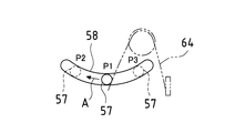
制御部45は、カム駆動部63を駆動制御しており、その出力軸を回動させて、各偏芯カム59を回動させ、図8及び図10に示す様に支軸57及び各従動排紙ローラ33を各ポジションP1、P2、P3のいずれかに位置決めする。
The
また、各駆動排紙ローラ33aの表層の硬度を各従動排紙ローラ33bの表層の硬度よりも高くし、各駆動排紙ローラ33aの半径と各従動排紙ローラ33bの半径の和よりも、駆動軸51の中心と支軸57の中心との距離を短くしている。このため、図10に示す様に各従動排紙ローラ33bが各駆動排紙ローラ33aに押圧されて変形し、各駆動排紙ローラ33aと各従動排紙ローラ33b間に幅広いニップ域Nが形成される。このため、各駆動排紙ローラ33aが回転駆動されると、各従動排紙ローラ33bが従動回転し、ニップ域Nに記録用紙を確実に挟み込んで、各駆動排紙ローラ33aと各従動排紙ローラ33bにより記録用紙を確実に搬送することができる。
Further, the hardness of the surface layer of each driven
また、図10に示す様に各従動排紙ローラ33bが各駆動排紙ローラ33aの周りを移動しても、支軸57と駆動軸51間の距離が一定に保持されるので、各従動排紙ローラ33bと各駆動排紙ローラ33a間に一定のニップ域Nが形成される。
Further, as shown in FIG. 10, even if each driven
さて、この様な構成において、図4(a)に示す様に反っていない記録用紙が上測距センサ43と下測距センサ44の中間を通過すると、制御部45は、上測距センサ43及び下測距センサ44の各検出出力によって示されるそれぞれの離間距離La、Lbが略一致することから、記録用紙が反っていいないと判定する。そして、制御部45は、この判定をなすと、カム駆動部63を駆動制御して、各偏芯カム59を回動させ、図4(b)に示す様に各従動排紙ローラ33bをポジションP1に位置決めする。この場合は、各駆動排紙ローラ33aと各従動排紙ローラ33b近傍での記録用紙の搬送軌道H1が直線に近似され、反っていない記録用紙が直線状の搬送軌道H1で搬送される。このため、記録用紙が、その反りを矯正されずにそのまま搬送されることになる。
In such a configuration, when a recording sheet that is not warped passes through the middle of the upper
また、図5(a)に示す様に上面側が凸状に反っている記録用紙が搬送されて来て上測距センサ43から遠のきかつ下測距センサ44に近づくと、制御部45は、上測距センサ43の検出出力によって示される離間距離Laが下測距センサ44の検出出力によって示される離間距離Lbよりも長いことから、記録用紙が凸状に反っていると判定する。そして、制御部45は、この判定をなすと、カム駆動部63を駆動制御して、各偏芯カム59を回動させ、図5(b)に示す様に各従動排紙ローラ33bをポジションP2に位置決めする。この場合は、各駆動排紙ローラ33aと各従動排紙ローラ33b近傍下流側の記録用紙の搬送軌道H2が凹状にされ、凸状に反っている記録用紙が凹状の搬送軌道H2でしごかれつつ搬送される。このときに記録用紙の搬送抵抗が大きくなっても、各駆動排紙ローラ33aと各従動排紙ローラ33b間のニップ域Nの幅が広いので、記録用紙が確実に搬送されてしごかれる。このため、記録用紙の凸状の反りが凹状の搬送軌道により矯正されて、記録用紙の反りが略無くなる。
Further, as shown in FIG. 5A, when a recording sheet having a convex upper surface is conveyed and is far from the
更に、図6(a)に示す様に上面側が凹状に反っている記録用紙が搬送されて来て上測距センサ43に近づきかつ下測距センサ44から遠のくと、制御部45は、上測距センサ43の検出出力によって示される離間距離Laが下測距センサ44の検出出力によって示される離間距離Lbよりも短いことから、記録用紙が凹状に反っていると判定する。そして、制御部45は、この判定をなすと、カム駆動部63を駆動制御して、各偏芯カム59を回動させ、図6(b)に示す様に各従動排紙ローラ33bをポジションP3に位置決めする。この場合は、各駆動排紙ローラ33aと各従動排紙ローラ33b近傍下流側の記録用紙の搬送軌道H3が凸状にされ、凹状に反っている記録用紙が凸状の搬送軌道H3でしごかれつつ搬送される。このときに記録用紙の搬送抵抗が大きくなっても、ニップ域Nの幅が広いので、記録用紙が確実に搬送されてしごかれる。このため、記録用紙の凹状の反りが凸状の搬送軌道により矯正されて、記録用紙の反りが略無くなる。
Further, as shown in FIG. 6A, when a recording sheet whose upper surface is warped in a concave shape is conveyed and approaches the upper
この様に本実施例では、記録用紙の反り状態に応じて、記録用紙の反りの矯正を適宜に行なっているので、種々の記録用紙に負担を与えることなく、その様々な反りを矯正することができ、スタッキング性が向上する。また、従来の様に記録用紙の搬送方向と直交する方向で記録用紙をしごいて波打たせないので、格別に薄い記録用紙にしわ等が発生したり、格別に厚い記録用紙の搬送不良や破損を招来したりすることがない。 In this way, in this embodiment, since the correction of the warping of the recording paper is appropriately performed according to the warping state of the recording paper, the various warping can be corrected without imposing a burden on the various recording papers. And stacking performance is improved. In addition, since the recording paper is not squeezed and undulated in the direction perpendicular to the recording paper conveyance direction as in the past, wrinkles or the like are generated on an exceptionally thin recording paper, the conveyance failure of an exceptionally thick recording paper, There will be no damage.
尚、本発明は、上記実施例に限定されるものではなく、多様に変形することができる。例えば、図11に示す様に上測距センサ43を残して、下測距センサ44を省略し、上測距センサ43のみの検出出力に基づいて、記録用紙の反りの状態を検出しても良い。この場合は、図11(a)に示す様に記録用紙が反っていなければ、記録用紙が上測距センサ43から略一定の距離(=L±α(αは許容値))の位置を通過することから、上測距センサ43の検出出力によって示される離間距離Laが略一定の距離に一致すると、記録用紙が反っていないと判定する。そして、図4(b)に示す様に各従動排紙ローラ33bをポジションP1に位置決めして、記録用紙の反りを矯正せずに、記録用紙をそのまま搬送する。
In addition, this invention is not limited to the said Example, It can deform | transform variously. For example, as shown in FIG. 11, the
また、図11(b)に示す様に上面側が凸状に反っている記録用紙であれば、記録用紙が上測距センサ43から略一定の距離を超えて遠のくことから、上測距センサ43の検出出力によって示される離間距離Laが略一定の距離を超えると、記録用紙が凸状に反っていると判定する。そして、図5(b)に示す様に各従動排紙ローラ33bをポジションP2に位置決めして、記録用紙の凸状の反りを凹状の搬送軌道により矯正して、記録用紙の反りを略無くす。
Further, as shown in FIG. 11B, if the recording sheet has a convex upper surface, the recording sheet moves away from the upper
更に、図11(c)に示す様に上面側が凹状に反っている記録用紙であれば、記録用紙が上測距センサ43へと略一定の距離よりも近づくことから、上測距センサ43の検出出力によって示される離間距離Laが略一定の距離よりも短ければ、記録用紙が凹状に反っていると判定する。そして、図6(b)に示す様に各従動排紙ローラ33bをポジションP3に位置決めして、記録用紙の凹状の反りを凸状の搬送軌道により矯正して、記録用紙の反りを略無くす。
Furthermore, as shown in FIG. 11C, if the recording sheet has a concave upper surface, the recording sheet approaches the upper
1 画像形成装置
3 原稿読取り装置
4 印字部
5 印字用紙搬送部
6 給紙部
7 排紙部
15 第1走査ユニット
16 第2走査ユニット
41、42 用紙ガイド
43 上測距センサ
44 下測距センサ
45 制御部
51 駆動軸
52 フレーム
53、62 軸受け
54、56 ギア
57 支軸
58 溝孔
59 偏芯カム
61 カム軸
DESCRIPTION OF
Claims (11)
搬送されて来た記録用紙を挟み込んで更に搬送する複数のローラと、
反り検出手段により検出された記録用紙の反り状態に応じて、各ローラの一方に対する他方の当接位置を変位させ、各ローラ近傍での記録用紙の搬送軌道を変更するローラ変位手段と
を備えることを特徴とする記録用紙の反り矯正装置。 A warp detecting means for detecting a warp state of the recording paper to be conveyed;
A plurality of rollers that sandwich and convey the recording paper that has been conveyed;
Roller displacement means for displacing the other abutment position of each roller with respect to one of the rollers according to the warpage state of the recording paper detected by the warp detection means, and changing the recording paper transport path in the vicinity of each roller. A warp correction device for recording paper.
An image forming apparatus using the warp correction apparatus according to claim 1.
Priority Applications (1)
| Application Number | Priority Date | Filing Date | Title |
|---|---|---|---|
| JP2004067461A JP2005255308A (en) | 2004-03-10 | 2004-03-10 | Warpage correction device for recording paper and image forming device using it |
Applications Claiming Priority (1)
| Application Number | Priority Date | Filing Date | Title |
|---|---|---|---|
| JP2004067461A JP2005255308A (en) | 2004-03-10 | 2004-03-10 | Warpage correction device for recording paper and image forming device using it |
Publications (1)
| Publication Number | Publication Date |
|---|---|
| JP2005255308A true JP2005255308A (en) | 2005-09-22 |
Family
ID=35081420
Family Applications (1)
| Application Number | Title | Priority Date | Filing Date |
|---|---|---|---|
| JP2004067461A Pending JP2005255308A (en) | 2004-03-10 | 2004-03-10 | Warpage correction device for recording paper and image forming device using it |
Country Status (1)
| Country | Link |
|---|---|
| JP (1) | JP2005255308A (en) |
Cited By (6)
| Publication number | Priority date | Publication date | Assignee | Title |
|---|---|---|---|---|
| JP2008071256A (en) * | 2006-09-15 | 2008-03-27 | Brother Ind Ltd | Browsing terminal |
| JP2008127199A (en) * | 2006-11-27 | 2008-06-05 | Kyocera Mita Corp | Transfer paper curl remover and image forming device |
| US9085178B2 (en) | 2013-01-07 | 2015-07-21 | Seiko Epson Corporation | Printing apparatus |
| JP2016208456A (en) * | 2015-04-28 | 2016-12-08 | シャープ株式会社 | Image forming apparatus |
| JP2017056732A (en) * | 2016-11-08 | 2017-03-23 | デュプロ精工株式会社 | Control method of sheet press-bonding device |
| JP7392448B2 (en) | 2019-12-17 | 2023-12-06 | コニカミノルタ株式会社 | Reading device, decal system, image forming system, and curl state detection method |
-
2004
- 2004-03-10 JP JP2004067461A patent/JP2005255308A/en active Pending
Cited By (6)
| Publication number | Priority date | Publication date | Assignee | Title |
|---|---|---|---|---|
| JP2008071256A (en) * | 2006-09-15 | 2008-03-27 | Brother Ind Ltd | Browsing terminal |
| JP2008127199A (en) * | 2006-11-27 | 2008-06-05 | Kyocera Mita Corp | Transfer paper curl remover and image forming device |
| US9085178B2 (en) | 2013-01-07 | 2015-07-21 | Seiko Epson Corporation | Printing apparatus |
| JP2016208456A (en) * | 2015-04-28 | 2016-12-08 | シャープ株式会社 | Image forming apparatus |
| JP2017056732A (en) * | 2016-11-08 | 2017-03-23 | デュプロ精工株式会社 | Control method of sheet press-bonding device |
| JP7392448B2 (en) | 2019-12-17 | 2023-12-06 | コニカミノルタ株式会社 | Reading device, decal system, image forming system, and curl state detection method |
Similar Documents
| Publication | Publication Date | Title |
|---|---|---|
| JP4176100B2 (en) | Image forming apparatus | |
| JP4242884B2 (en) | Sheet conveying apparatus, and document conveying apparatus and image processing apparatus provided with the same | |
| US7472905B2 (en) | Sheet conveying apparatus, image forming apparatus and image reading apparatus | |
| JP4111026B2 (en) | Image forming apparatus | |
| JP2004163931A (en) | Method for aligning sheet by double-sided copying machine for reducing distortion | |
| JP4717600B2 (en) | Sheet conveying apparatus and image forming apparatus | |
| JP2013018653A (en) | Image forming apparatus, image forming system and post processing apparatus which perform skew feeding correction | |
| JP2013237499A (en) | Sheet transport device, and image forming apparatus | |
| US8322714B2 (en) | Sheet conveying apparatus and image forming apparatus | |
| JP2010058961A (en) | Paper thickness detection device, paper-feeding device, picture reading device, and image forming device | |
| JP2006347644A (en) | Image forming apparatus | |
| JP2005255308A (en) | Warpage correction device for recording paper and image forming device using it | |
| US9769327B2 (en) | Image forming apparatus and method of positional adjustment in image formation | |
| JP2021195208A (en) | Sheet carrier, image reader and image forming apparatus | |
| JP2006347645A (en) | Image forming apparatus | |
| JP4717723B2 (en) | Recording material detector | |
| JP3882533B2 (en) | Paper conveying apparatus and image forming apparatus | |
| JP7135784B2 (en) | MEDIUM THICKNESS DETECTION DEVICE, MEDIUM CONVEYING DEVICE, AND IMAGE FORMING APPARATUS | |
| JP7002001B2 (en) | Sheet detection device, transfer device, image forming device, sheet detection position adjustment method | |
| JP2022052462A (en) | Image reading device and image forming apparatus | |
| JP2001058741A (en) | Sheet transport device, image forming device, and image reading device | |
| JP6901699B2 (en) | Document transfer device and image forming device | |
| JP2010083644A (en) | Sheet detecting device and image forming device | |
| JP3347656B2 (en) | Sheet transport device | |
| JP2005269601A (en) | Document feeding and reading unit and image forming apparatus |