JP7516593B2 - 画像形成装置 - Google Patents
画像形成装置 Download PDFInfo
- Publication number
- JP7516593B2 JP7516593B2 JP2023025875A JP2023025875A JP7516593B2 JP 7516593 B2 JP7516593 B2 JP 7516593B2 JP 2023025875 A JP2023025875 A JP 2023025875A JP 2023025875 A JP2023025875 A JP 2023025875A JP 7516593 B2 JP7516593 B2 JP 7516593B2
- Authority
- JP
- Japan
- Prior art keywords
- fixing
- recording material
- stay
- guide
- image forming
- Prior art date
- Legal status (The legal status is an assumption and is not a legal conclusion. Google has not performed a legal analysis and makes no representation as to the accuracy of the status listed.)
- Active
Links
Images


Landscapes
- Fixing For Electrophotography (AREA)
- Electrophotography Configuration And Component (AREA)
Description
実施例1に係る画像形成装置について図1から図6を用いて説明する。
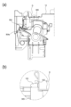
まず画像形成装置の動作について図1を用いて説明する。図1の右側が画像形成装置の本体前面側、左側が本体背面側としている。また、画像形成装置における定着器の構成については図2を用いて説明する。
下搬送ガイド903は、上搬送ガイド904と対向し、定着ローラ対901の圧接部よりも記録材の搬送方向の下流側で記録材Sの加圧部材側である加圧ローラ側の面をガイドする第2の搬送ガイドである。下搬送ガイド903は、上搬送ガイド904と対向する面に、複数の下搬送リブ903aを備えている。下搬送ガイド903の下搬送リブ903aは、記録材Sの加圧部材側の面を搬送方向にガイドするリブであり、記録材Sの搬送方向と直交する幅方向に複数設けられている。
上搬送ガイド904は、定着ローラ対901の圧接部よりも記録材の搬送方向の下流側で記録材Sの加熱部材側である加熱ローラ側の面をガイドする搬送ガイドである。
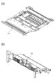
次に実施例2に係る画像形成装置について図7および図8を用いて説明する。
図7は本実施例における定着カバー905を斜め下から見た図であり、図8は本実施例における定着カバー905を本体背面側から見た図である。
次に実施例3に係る画像形成装置について図9および図10を用いて説明する。
本実施例では、定着カバー905の上部に、スキャナステー12に係合可能なフック部931を設けている。また、スキャナステー12には、前記フック部931と係合する穴部121を設けている。
前述した実施例では、搬送ガイドを一体形成した定着カバー又はスキャナステーの幅方向中央部に1つの突出部を設けた構成を例示したが、これに限定されるものではない。定着カバー又はスキャナステーの幅方向中央部に複数の突出部を設けた構成としても良い。
1 …画像形成装置
7 …スキャナユニット
9 …定着器
12 …スキャナステー
12a …曲げ部
13 …本体右側板
14 …本体左側板
15 …本体フレーム
121 …穴部
122 …突出部
123 …フック部
901 …定着ローラ対
901a …加熱ローラ
901b …加圧ローラ
902 …定着下ステー
903 …下搬送ガイド
903a …下搬送リブ
904 …上搬送ガイド
904a …上搬送リブ
905 …定着カバー
906 …突出部
911 …センサフラグ
912 …定着右側板
913 …定着左側板
931 …フック部
932 …穴部
Claims (3)
- 記録材にトナー像を形成する画像形成装置であって、
二つの側板と、前記二つの側板の間で前記二つの側板に支持されており、記録材の搬送方向と直交する記録材の幅方向に亘って設けられた材質が金属であるステーと、を有する前記画像形成装置の本体フレームと、
記録材に形成されたトナー像を記録材に定着する定着器であって、前記定着器の定着ニップ部を通過した記録材をガイドする材質が樹脂である搬送ガイドを有する前記定着器と、を有し、
前記搬送ガイドは、前記幅方向における前記搬送ガイドの中央部に前記ステーに向かって突出する突出部を備え、
前記突出部と前記ステーが当接することにより前記搬送ガイドの反りが抑えられる構造になっていることを特徴とする画像形成装置。 - 前記ステーは、曲げ線が前記幅方向と平行な曲げ部を有し、
前記突出部と前記ステーの前記曲げ部に相当する位置が当接することにより前記搬送ガイドの反りが抑えられる構造になっていることを特徴とする請求項1に記載の画像形成装置。 - 前記突出部は前記ステーから離間しており、前記突出部と前記ステーとの隙間は、前記搬送ガイドの前記幅方向における前記突出部以外の部分と前記ステーとの隙間よりも小さいことを特徴とする請求項1又は2に記載の画像形成装置。
Priority Applications (1)
| Application Number | Priority Date | Filing Date | Title |
|---|---|---|---|
| JP2023025875A JP7516593B2 (ja) | 2018-12-18 | 2023-02-22 | 画像形成装置 |
Applications Claiming Priority (2)
| Application Number | Priority Date | Filing Date | Title |
|---|---|---|---|
| JP2018235979A JP7233912B2 (ja) | 2018-12-18 | 2018-12-18 | 画像形成装置 |
| JP2023025875A JP7516593B2 (ja) | 2018-12-18 | 2023-02-22 | 画像形成装置 |
Related Parent Applications (1)
| Application Number | Title | Priority Date | Filing Date |
|---|---|---|---|
| JP2018235979A Division JP7233912B2 (ja) | 2018-12-18 | 2018-12-18 | 画像形成装置 |
Publications (2)
| Publication Number | Publication Date |
|---|---|
| JP2023054235A JP2023054235A (ja) | 2023-04-13 |
| JP7516593B2 true JP7516593B2 (ja) | 2024-07-16 |
Family
ID=71106500
Family Applications (2)
| Application Number | Title | Priority Date | Filing Date |
|---|---|---|---|
| JP2018235979A Active JP7233912B2 (ja) | 2018-12-18 | 2018-12-18 | 画像形成装置 |
| JP2023025875A Active JP7516593B2 (ja) | 2018-12-18 | 2023-02-22 | 画像形成装置 |
Family Applications Before (1)
| Application Number | Title | Priority Date | Filing Date |
|---|---|---|---|
| JP2018235979A Active JP7233912B2 (ja) | 2018-12-18 | 2018-12-18 | 画像形成装置 |
Country Status (1)
| Country | Link |
|---|---|
| JP (2) | JP7233912B2 (ja) |
Citations (3)
| Publication number | Priority date | Publication date | Assignee | Title |
|---|---|---|---|---|
| JP2006017794A (ja) | 2004-06-30 | 2006-01-19 | Fuji Xerox Co Ltd | 定着装置及び画像形成装置 |
| JP2014063010A (ja) | 2012-09-21 | 2014-04-10 | Brother Ind Ltd | 画像形成装置 |
| JP2015072337A (ja) | 2013-10-02 | 2015-04-16 | キヤノン株式会社 | 画像形成装置 |
Family Cites Families (1)
| Publication number | Priority date | Publication date | Assignee | Title |
|---|---|---|---|---|
| JP3609257B2 (ja) * | 1998-05-19 | 2005-01-12 | 株式会社リコー | 自動原稿搬送装置 |
-
2018
- 2018-12-18 JP JP2018235979A patent/JP7233912B2/ja active Active
-
2023
- 2023-02-22 JP JP2023025875A patent/JP7516593B2/ja active Active
Patent Citations (3)
| Publication number | Priority date | Publication date | Assignee | Title |
|---|---|---|---|---|
| JP2006017794A (ja) | 2004-06-30 | 2006-01-19 | Fuji Xerox Co Ltd | 定着装置及び画像形成装置 |
| JP2014063010A (ja) | 2012-09-21 | 2014-04-10 | Brother Ind Ltd | 画像形成装置 |
| JP2015072337A (ja) | 2013-10-02 | 2015-04-16 | キヤノン株式会社 | 画像形成装置 |
Also Published As
| Publication number | Publication date |
|---|---|
| JP2020098255A (ja) | 2020-06-25 |
| JP7233912B2 (ja) | 2023-03-07 |
| JP2023054235A (ja) | 2023-04-13 |
Similar Documents
| Publication | Publication Date | Title |
|---|---|---|
| US8611802B2 (en) | Fixing device | |
| US8720888B2 (en) | Image forming apparatus with a feeding unit including a plurality of ribs | |
| US8478176B2 (en) | Fixing apparatus | |
| US9494904B2 (en) | Separation device, fixing device, and image forming apparatus | |
| US6618577B2 (en) | Sheet guiding device with electromagnetic shield plate serving as one guide surface and image forming apparatus including the same | |
| US11243487B2 (en) | Heating unit with support member and image processing apparatus incorporating a heating unit | |
| US20110211882A1 (en) | Fixing Device | |
| US10996614B2 (en) | Part positioning mechanism and image forming apparatus | |
| US10042294B2 (en) | Separation device, fixing device, and image forming apparatus | |
| US20200209799A1 (en) | Sheet discharging apparatus and image forming apparatus | |
| US9042807B2 (en) | Image formation apparatus | |
| US9541871B2 (en) | Fixing device having stay and cover fixed thereto by spring | |
| JP7516593B2 (ja) | 画像形成装置 | |
| JP6493129B2 (ja) | 画像形成装置 | |
| US20080213012A1 (en) | Discharge guide and image forming apparatus having the same | |
| JP5393223B2 (ja) | 画像形成装置およびシート搬送装置 | |
| JP2019156614A (ja) | シート搬送装置およびそれを備えた画像形成装置 | |
| US9393812B2 (en) | Image forming apparatus | |
| JP2022118777A (ja) | 画像形成装置 | |
| JP7726056B2 (ja) | 定着装置及び画像形成装置 | |
| US11971672B2 (en) | Sheet conveying device and image forming apparatus | |
| JP6494237B2 (ja) | シート給送装置及び画像形成装置 | |
| US20240267475A1 (en) | Image reading apparatus and image forming apparatus | |
| JP2011235970A (ja) | シート受け機構および画像形成装置 | |
| JP2024160749A (ja) | 画像形成装置 |
Legal Events
| Date | Code | Title | Description |
|---|---|---|---|
| A621 | Written request for application examination |
Free format text: JAPANESE INTERMEDIATE CODE: A621 Effective date: 20230324 |
|
| A521 | Request for written amendment filed |
Free format text: JAPANESE INTERMEDIATE CODE: A523 Effective date: 20230330 |
|
| A977 | Report on retrieval |
Free format text: JAPANESE INTERMEDIATE CODE: A971007 Effective date: 20240131 |
|
| A131 | Notification of reasons for refusal |
Free format text: JAPANESE INTERMEDIATE CODE: A131 Effective date: 20240305 |
|
| A521 | Request for written amendment filed |
Free format text: JAPANESE INTERMEDIATE CODE: A523 Effective date: 20240502 |
|
| TRDD | Decision of grant or rejection written | ||
| A01 | Written decision to grant a patent or to grant a registration (utility model) |
Free format text: JAPANESE INTERMEDIATE CODE: A01 Effective date: 20240604 |
|
| A61 | First payment of annual fees (during grant procedure) |
Free format text: JAPANESE INTERMEDIATE CODE: A61 Effective date: 20240703 |
|
| R150 | Certificate of patent or registration of utility model |
Ref document number: 7516593 Country of ref document: JP Free format text: JAPANESE INTERMEDIATE CODE: R150 |