JP7516593B2 - Image forming device - Google Patents
Image forming device Download PDFInfo
- Publication number
- JP7516593B2 JP7516593B2 JP2023025875A JP2023025875A JP7516593B2 JP 7516593 B2 JP7516593 B2 JP 7516593B2 JP 2023025875 A JP2023025875 A JP 2023025875A JP 2023025875 A JP2023025875 A JP 2023025875A JP 7516593 B2 JP7516593 B2 JP 7516593B2
- Authority
- JP
- Japan
- Prior art keywords
- fixing
- recording material
- stay
- guide
- image forming
- Prior art date
- Legal status (The legal status is an assumption and is not a legal conclusion. Google has not performed a legal analysis and makes no representation as to the accuracy of the status listed.)
- Active
Links
Images


Landscapes
- Fixing For Electrophotography (AREA)
- Electrophotography Configuration And Component (AREA)
Description
本発明は、記録材に形成されたトナー像を加熱して定着する定着器を備えた画像形成装置に関するものである。 The present invention relates to an image forming apparatus equipped with a fixing device that heats and fixes a toner image formed on a recording material.
従来の画像形成装置において、定着器に送られた記録材は、加熱ローラと加圧ローラからなる定着ローラ対の圧接部にてトナー像が加熱されて定着される。定着ローラ対を通過した記録材は、定着器内に設けられた上ガイドと下ガイドとの間を通過する。ここで、上ガイドと下ガイドとの間には、記録材の先端および後端が検知可能なセンサフラグが配置されている。 In conventional image forming devices, the toner image on the recording material sent to the fixing unit is heated and fixed at the pressure contact area of a pair of fixing rollers consisting of a heating roller and a pressure roller. The recording material that has passed through the pair of fixing rollers passes between an upper guide and a lower guide provided in the fixing unit. Here, a sensor flag that can detect the leading and trailing ends of the recording material is arranged between the upper and lower guides.
上ガイドと下ガイドで形成される搬送路の広さは、センサフラグでの記録材の先端および後端の検知精度を向上させるために狭い方が良い。これは搬送路が狭いほど、搬送中の記録材の姿勢の変化が小さくなるためである。一方、記録材が厚い場合や硬い場合、搬送路が狭すぎると記録材自身の屈曲により搬送抵抗が増加し、搬送速度が低下することがある。よって、搬送路の広さは、記録材が厚い場合や硬い場合でも速度が低下することなく、かつ、センサ検知精度を向上させるために、適度な広さを保つことが重要である。 The width of the transport path formed by the upper and lower guides should be narrow to improve the accuracy of detection of the leading and trailing ends of the recording material by the sensor flag. This is because the narrower the transport path, the smaller the change in the posture of the recording material during transport. On the other hand, if the recording material is thick or hard, if the transport path is too narrow, the bending of the recording material itself can increase transport resistance and reduce the transport speed. Therefore, it is important to maintain an appropriate width for the transport path so that the speed does not decrease even when the recording material is thick or hard, and to improve sensor detection accuracy.
ここで、上ガイドおよび下ガイドは、記録材の搬送方向に対して直交する幅方向(以下、長手方向と呼ぶ)に長い部品であり、樹脂材料でもあるため、成形時に変形が発生し、搬送路が広くなることがある。 The upper and lower guides are long in the width direction (hereafter referred to as the longitudinal direction) perpendicular to the recording material transport direction, and are made of resin, so deformation can occur during molding, causing the transport path to become wider.
また、上ガイドと下ガイドの間の搬送路が上ガイド側に湾曲している場合、記録材が厚い場合や硬い場合、記録材の剛性によって、上ガイドが搬送路が広がる側に押し上げられる場合がある。この場合、記録材の加熱ローラ側の面を案内する上ガイドは、押し上げられた状態で加熱ローラからの熱を受け、押し上げられた状態を維持するように変形し、その結果、搬送路が広くなることがある。 In addition, if the transport path between the upper and lower guides is curved towards the upper guide, and if the recording material is thick or hard, the upper guide may be pushed up towards the side where the transport path widens due to the rigidity of the recording material. In this case, the upper guide, which guides the surface of the recording material facing the heating roller, receives heat from the heating roller in a pushed-up state and deforms to maintain the pushed-up state, which may result in the transport path widening.
これに対して従来は、上ガイドの肉厚を増やすことで剛性を高めたり、あるいは外力や熱による変形に強い特殊な樹脂材料を使用するという手段で対応してきた。 In the past, this issue was addressed by increasing the thickness of the upper guide to increase its rigidity, or by using a special resin material that is resistant to deformation caused by external forces or heat.
また、特許文献1の定着器が開示されている。特許文献1の定着器は、定着ローラ対を通過した記録材を搬送方向の下流側に導く搬送路を構成する上ガイドおよびフラッパを有しており、画像形成装置の本体フレームに取り付けられている。さらに特許文献1の定着器は、前記上ガイドとは別に定着器のフレーム部材に対して固定の上カバーを設け、前記上ガイドに前記上カバーと当接するように突起部を設けている。これにより、上ガイドが加熱ローラ側からの熱で搬送路と反対方向に向かって変形しようとしても、上ガイドの突起部が上カバーに当接して変形が押さえられる。
しかしながら、特許文献1の定着器では、突起部を突き当てる上カバーの追加により定着器がコストアップするとともに大型化してしまい、その定着器の設置スペースを確保するために画像形成装置が大型化してしまうという課題がある。
However, the fixing unit of
そこで、本発明の目的は、定着器の部品を追加することなく、安定して定着器の搬送路の広さを確保することである。 The object of the present invention is to stably ensure the width of the fixing unit's transport path without adding any additional fixing unit parts.
上記目的を達成するための本発明の代表的な構成は、記録材にトナー像を形成する画像形成装置であって、二つの側板と、前記二つの側板の間で前記二つの側板に支持されており、記録材の搬送方向と直交する記録材の幅方向に亘って設けられた材質が金属であるステーと、を有する前記画像形成装置の本体フレームと、記録材に形成されたトナー像を記録材に定着する定着器であって、前記定着器の定着ニップ部を通過した記録材をガイドする材質が樹脂である搬送ガイドを有する前記定着器と、を有し、前記搬送ガイドは、前記幅方向における前記搬送ガイドの中央部に前記ステーに向かって突出する突出部を備え、前記突出部と前記ステーが当接することにより前記搬送ガイドの反りが抑えられる構造になっていることを特徴とする。 A typical configuration of the present invention for achieving the above-mentioned object is an image forming device that forms a toner image on a recording material, the image forming device having a main body frame having two side panels and a stay that is supported by the two side panels between the two side panels and is made of metal and is arranged across the width direction of the recording material perpendicular to the transport direction of the recording material, and a fixation device that fixes the toner image formed on the recording material to the recording material, the fixation device having a transport guide made of resin that guides the recording material that has passed through a fixing nip portion of the fixation device, the transport guide having a protrusion that protrudes toward the stay at the center of the transport guide in the width direction, and a structure in which the protrusion and the stay abut against each other to suppress warping of the transport guide.
本発明によれば、定着器の部品を追加することなく、安定して定着器の搬送路の広さを確保することができる。 According to the present invention, it is possible to stably ensure the width of the conveying path of the fixing unit without adding any parts to the fixing unit.
以下、図面を参照して、本発明の好適な実施の形態を例示的に詳しく説明する。ただし、以下の実施形態に記載されている構成部品の寸法、材質、形状、それらの相対配置などは、本発明が適用される装置の構成や各種条件により適宜変更されるべきものである。従って、特に特定的な記載がない限りは、本発明の範囲をそれらのみに限定する趣旨のものではない。 The following describes in detail the preferred embodiments of the present invention by way of example, with reference to the drawings. However, the dimensions, materials, shapes, and relative positions of the components described in the following embodiments should be modified as appropriate depending on the configuration and various conditions of the device to which the present invention is applied. Therefore, unless otherwise specified, it is not intended to limit the scope of the present invention to only those.
〔実施例1〕
実施例1に係る画像形成装置について図1から図6を用いて説明する。
Example 1
An image forming apparatus according to a first embodiment will be described with reference to FIGS. 1 to 6. FIG.
(画像形成装置全体の説明)
まず画像形成装置の動作について図1を用いて説明する。図1の右側が画像形成装置の本体前面側、左側が本体背面側としている。また、画像形成装置における定着器の構成については図2を用いて説明する。
(Overall description of image forming apparatus)
First, the operation of the image forming apparatus will be described with reference to Fig. 1. The right side of Fig. 1 is the front side of the main body of the image forming apparatus, and the left side is the rear side of the main body. The configuration of the fixing unit in the image forming apparatus will be described with reference to Fig. 2.
図1に示すように、記録材Sは、画像形成装置1の下部に設けられたカセット2に積載収納される。カセット2に積載収納された記録材Sは、給紙ローラ3によってカセット2から給紙される。給紙された記録材Sは、搬送ローラ対4、レジストローラ対5を経て、感光体601を備えた画像形成プロセスユニット6に搬送される。スキャナユニット7から照射されたレーザー光が図1中時計回り方向に回転している感光体601上に照射され、感光体601上に静電潜像が形成される。この静電潜像は画像形成プロセスユニット6内の現像部(不図示)にてトナー像が現像される。感光体601上に形成されたトナー像は転写ローラ8により記録材Sに転写される。トナー像が転写された記録材Sは、定着器9内の加熱ローラ901aと加圧ローラ901bとからなる定着ローラ対901により熱、圧力が加えられる。これによりトナー像は記録材Sに定着される。その後、記録材Sは排紙ローラ対10を通過し、排紙トレイ11上に排出される。
As shown in FIG. 1, the recording material S is stacked and stored in a
ここで、図中の矢印Aは記録材の通紙方向を示している。また、定着器9は画像形成装置1の本体フレーム15(図4(a)参照)に対して取り付けられ、固定ビス(不図示)により固定されている。従って、メンテナス等において、定着器9は固定ビス(不図示)を外すことによって、画像形成装置1の本体フレーム15に対して着脱可能である。
Here, arrow A in the figure indicates the direction in which the recording material passes. The
図2に示すように、定着器9は、加熱部材である加熱ローラ901aと加圧部材である加圧ローラ901bとからなる定着ローラ対901を備えている。ヒーターを有する加熱ローラ901aと加圧ローラ901bの圧接部にて記録材を挟持搬送し記録材に形成されたトナー像を加熱して定着する。
As shown in FIG. 2, the
定着器9内には、定着ローラ対901の圧接部に対して、記録材Sの搬送方向に対する上流側の下方に定着入口ガイド909、下流側の下方に下搬送ガイド903、定着ローラ対901を覆うように定着カバー905が設けられている。また、定着カバー905には定着ローラ対901に対して記録材Sの搬送方向に対する下流側の上方に上搬送ガイド904が一体的に形成されている。定着カバー905及び搬送ガイド904は、PET(ポリエチレンテレフタレート)樹脂やPBT(ポリブチレンテレフタレート)樹脂などの耐熱性を重視した樹脂材料で形成されている。上搬送ガイド904は、下搬送ガイド903と対向する面に、複数の上搬送リブ904aを備えている。上搬送ガイド904の上搬送リブ904aは、記録材Sの加熱部材側の面を搬送方向にガイドするリブである。また、上搬送ガイド904には定着出口アイドラローラ910が回転可能に設けられている。定着出口アイドラローラ910は、上搬送ガイド904の上搬送リブ904aより搬送路に突出するように配置されている。
In the
感光体601と転写ローラ8を通過した記録材Sは、定着入口ガイド909に案内されながら定着ローラ対901に到達する。定着ローラ対901を通過した記録材Sは、定着器9内に設けられた下搬送ガイド903と上搬送ガイド904および定着出口アイドラローラ910との間を通過する。ここで、下搬送ガイド903と上搬送ガイド904との間には、上搬送ガイド904と下搬送ガイド903との間の搬送路において記録材Sの先端および後端を検知するためのセンサフラグ911が設けられている。
The recording material S that has passed through the
(下搬送ガイドの説明)
下搬送ガイド903は、上搬送ガイド904と対向し、定着ローラ対901の圧接部よりも記録材の搬送方向の下流側で記録材Sの加圧部材側である加圧ローラ側の面をガイドする第2の搬送ガイドである。下搬送ガイド903は、上搬送ガイド904と対向する面に、複数の下搬送リブ903aを備えている。下搬送ガイド903の下搬送リブ903aは、記録材Sの加圧部材側の面を搬送方向にガイドするリブであり、記録材Sの搬送方向と直交する幅方向に複数設けられている。
(Explanation of the lower transport guide)
The lower conveying
本実施例における下搬送ガイド903は樹脂材料で形成されたものであり、下搬送ガイド903は、記録材Sの搬送方向に対して直交する幅方向に長い部品である。そのため、成形時の変形(ソリと呼ぶ)が発生する場合があり、下搬送リブ903aの位置精度を維持することが難しい。なお、記録材Sの搬送方向に対して直交する幅方向を、以下、搬送ガイドの長手方向とも呼ぶ。図2(b)に示す矢印A方向は定着ローラ対901の圧接部を通過する記録材Sの搬送方向である。図4(a)に示す矢印H方向は前記記録材Sの搬送方向である矢印A方向と直交する記録材Sの幅方向であり、定着カバー905の長手方向である。
The lower conveying
ここで、本実施例における定着器9は、金属製で剛性が高く、精度が良い定着下ステー902と、定着右側板912と、定着左側板913とにより構成された定着フレームを備えている。定着右側板912は定着下ステー902の長手方向の一方側に設けられ、定着左側板913は定着下ステー902の長手方向の他方側に設けられている。定着下ステー902の長手方向両側に設けた側板912,913により加熱ローラ901aと加圧ローラ901bを支持している。
The fixing
なお、ここでは定着フレームとして、定着下ステー902に対して定着右側板912と定着左側板913を別体で設けた構成を例示したが、これに限定されるものではない。定着フレームは、定着下ステー902の長手方向の両側を曲げ加工するなどして定着右側板912と定着左側板913を定着下ステー902に一体に設けた構成としても良い。
Note that, although the fixing frame is exemplified here as having a configuration in which the fixing
また、本実施例における定着左側板913と定着右側板912は加圧機構(不図示)を備えている。加熱ローラ901aは加圧機構によって加圧ローラ901bに向かって押し付けられる構成となっている。
In addition, in this embodiment, the
下搬送ガイド903は、記録材Sの搬送方向と直交する幅方向にわたって設けられた定着下ステー902にならわせて固定されている。これにより、下搬送ガイド903は、成形時に発生したソリが定着下ステー902によって矯正され、対向する上搬送ガイド904との間の搬送路の広さの精度の向上を実現している。
The lower conveying
(上搬送ガイドの説明)
上搬送ガイド904は、定着ローラ対901の圧接部よりも記録材の搬送方向の下流側で記録材Sの加熱部材側である加熱ローラ側の面をガイドする搬送ガイドである。
(Explanation of the upper transport guide)
The upper conveying
本実施例における上搬送ガイド904は、定着ローラ対901の上部を覆う定着カバー905に一体に形成されている。定着カバー905は複雑な形状を一体に形成するため、樹脂材料で形成されている。また、上搬送ガイド904は、下搬送ガイド903と対向する面に、複数の上搬送リブ904aを備えている。上搬送ガイド904の上搬送リブ904aは、記録材Sの加熱部材側の面を搬送方向(図2(b)に示す矢印A方向)にガイドするリブであり、記録材Sの搬送方向と直交する幅方向(図4(a)に示す矢印H方向)に複数設けられている。また、前述したように、上搬送ガイド904には、定着出口アイドラローラ910が記録材の搬送方向に回転可能に設けられている。定着出口アイドラローラ910は、その外周面が上搬送ガイド904の搬送リブ904aから搬送路に突出するように配置されている。本実施例において上搬送リブ904aと定着出口アイドラローラ910の位置は、上搬送ガイド904の成形条件の調整により精度を向上させている。また、本実施例に係る定着器9においては、省スペース化と部品点数削減のため、上搬送ガイド904のソリを矯正するための金属製のステーは追加しない。
In this embodiment, the upper conveying
ここで記録材Sが厚い場合や硬い場合(厚紙と呼ぶ)の通紙中における上搬送ガイド904の変形について図3を用いて説明する。
Here, we will use Figure 3 to explain how the upper conveying
定着器9を通紙中の記録材Sは、下流側の排紙ローラ対10(図1参照)により搬送されることで図2(b)に示す矢印A方向に引っ張られる。これにより、記録材Sは、上搬送ガイド904に備えらえた定着出口アイドラローラ910に対して、図3に示す矢印F方向に力を付与される。この矢印F方向の力は、記録材Sが厚く、硬いほど大きくなる。また、この矢印F方向の力は、定着ローラ対901を抜けた後の下搬送リブ903aと上搬送リブ904aによって形成される搬送路の立ち上がりが急激なほど大きくなる。この矢印F方向の力により、上搬送ガイド904は図3における上方向に押し上げられる。
The recording material S passing through the fixing
ここで、加熱ローラ901aの熱により上搬送ガイド904は熱せられている状態となっている。すなわち、初期に上搬送ガイドの部品精度を向上させたとしても、記録材Sが厚紙であった場合は、通紙中の上搬送ガイドは上向きの強い力で押し上げられると共に熱が加えられる。これにより、上搬送ガイド904は上向きに変形する。この変形は上搬送ガイド904が冷却されても元には戻りにくく、その結果、対向する下搬送ガイド903との間に形成される搬送路が広い状態になってしまう。
At this point, the
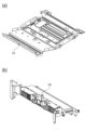
これに対して、本実施例では、定着器9を取り付ける画像形成装置の本体フレームを構成する部品を用いて解決する。図4(a)は本体フレーム構成と定着器9を抜粋して背面から見た図である。また、図4(b)は中央部(図4(a)に示すC部)を拡大したものである。また、図4(c)は中央部(図4(a)に示すC部)を拡大したものであり、図4(b)の他の構成例を示すものである。
In contrast, this embodiment solves this problem by using parts that make up the main body frame of the image forming device to which the
画像形成装置1の本体フレーム15は、記録材Sの搬送方向と直交する幅方向の一方側に設けられた本体右側板13と、幅方向の他方側に設けられた本体左側板14と、本体右側板13と本体左側板14に支持されたスキャナステー12とにより構成されている。本体フレーム15は、本体右側板13と本体左側板14とスキャナステー12とによって、記録材Sの搬送方向と直交する幅方向にわたって設けられている。定着器9の定着カバー905の上部には、本体フレーム15を構成するスキャナステー12が配置されている。本体フレーム15のスキャナステー12には、画像形成プロセスに係るプロセス装置が取り付けられている。ここでは、プロセス装置として、像担持体である感光体601に画像情報に応じたレーザー光を走査する光走査装置を例示している。すなわち、本体フレーム15を構成するスキャナステー12は、図1に示すように感光体601にレーザー光を照射する光走査装置であるスキャナユニット7を支持している。スキャナユニット7は、図4に示す本体フレーム15において、スキャナステー12の取付部12bに取り付けられる。スキャナステー12は、剛性が高く、精度が高い板金部品である。
The
また、定着器9とスキャナステー12の間において定着カバー905には、記録材Sの搬送方向と直交する幅方向の中央部に周辺形状より本体フレーム側に突出した、前記スキャナステー12に当接可能な突出部906が設けられている。
The fixing
ここで、記録材Sの搬送方向と直交する幅方向とは、図4(a)に示す定着カバー905の長手方向である。突出部906が設けられた、定着カバー905の長手方向の中央部とは、前記幅方向の中央を基準に搬送される記録材Sの幅方向の最小サイズの領域である。本実施例では、前記幅方向の最小サイズの記録材Sに合わせて、幅方向の中央を基準に対称な位置に定着出口アイドラローラ910,910を設けている。なお、ここでは、突出部906が設けられた、定着カバー905の長手方向の中央部とは、図4(a)に示すように定着出口アイドラローラ910,910の内側の領域Gとしている。定着出口アイドラローラ910は、図3に示すように、上搬送ガイド914に回転可能に設けられ、上搬送ガイド914の上搬送リブ914aよりも搬送路内に突出するように設けられている。このため、定着器9を通紙中の記録材Sは、下流側の排紙ローラ対10(図1参照)により搬送されることで図2(b)に示す矢印A方向に引っ張られる。これにより、記録材Sは、上搬送ガイド904に設けられた定着出口アイドラローラ910に対して、図3に示す矢印F方向に力を付与される。定着カバー905は、長手方向の中央部が両側に比べて変形しやすい。このため、突出部906を、定着カバー905の長手方向の中央部に設けている。これにより、定着カバー905に一体形成された上搬送ガイド914の変形を防ぐことができ、搬送路の広さを精度良く保つことができる。
Here, the width direction perpendicular to the conveying direction of the recording material S is the longitudinal direction of the fixing
なお、ここでは、突出部906が設けられた、定着カバー905の長手方向の中央部を、図4(a)に示す定着出口アイドラローラ910,910の内側の領域Gとしたが、これに限定されるものではない。例えば、定着カバー905(の上搬送ガイド)に定着出口アイドラローラを設けない構成であっても、図4(a)に示す長手方向の中央部(領域G)に突出部906を設けることで同様の効果が得られる。また、定着カバー905の長手方向の中央部に突出部を設けるのは、長手方向の両側に比べて中央部が変形しやすいからである。そのため、突出部を設ける、定着カバーの長手方向の中央部の領域は、定着カバーを形成する材料・肉厚、配置構成などに応じて、適宜設定されるべき範囲であり、図4(a)に示す領域Gは、おおよその範囲である。
Here, the longitudinal center of the fixing
また、定着出口アイドラローラ910を定着カバー905(の上搬送ガイド)の長手方向中央部(領域G)の両側に設けた構成を例示したが、これに限定されるものではない。例えば、前記長手方向の中央(領域Gの中央)に1つ設けるなど、定着出口アイドラローラ910の数、配置は適宜設定すれば良い。
In addition, although the configuration in which the fixing exit
また、図4(b)に示すように、突出部906はスキャナステー12に当接している。なお、ここでは突出部906とスキャナステー12の間は0mmに設定されており、定着カバー905の突出部以外の部分905aとスキャナステー12との隙間t2は1mmに設定されている。
As shown in FIG. 4B, the protruding
しかし、この構成に限定されるものではない。例えば、図4(c)に示すように、突出部906はスキャナステー12から離間していても良い。この場合、定着カバー905とスキャナステー12の間において、前記突出部906とスキャナステー12との隙間t1は、定着カバー905の突出部以外の部分905aとスキャナステー12との隙間t2よりも小さい設定となっている。例えば、突出部906とスキャナステー12との隙間t1を0.5mm、定着カバー905の突出部以外の部分905aとスキャナステー12との隙間t2を1mmに設定しても良い。なお、隙間t1,t2は適宜設定されるべきものであり、これに限定されるものではない。
However, this is not a limitation. For example, as shown in FIG. 4(c), the protruding
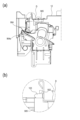
また、図5(a)はスキャナステー12と定着器9の概略断面図である。図5(b)および図5(c)は図5(a)に示すD部の拡大図である。図5(b)は図4(b)に示す突出部906とスキャナステー12との当接部の拡大図である。図5(c)は図4(c)に示す突出部906とスキャナステー12との対向部の拡大図である。図5(a)および図5(b)に示すように、スキャナステー12は、定着カバー905の上方において定着器9とは反対側に曲げられた曲げ部12aを有している。定着カバー905の突出部906はスキャナステー12の曲げ部12aの下方に当接されている。
Also, FIG. 5(a) is a schematic cross-sectional view of the
すなわち、本体フレームの構成要素の一つであるスキャナステー12に定着カバー905の突出部906を突き当てることで、定着器に新たなステーを追加することなく、上搬送ガイド904の矢印F方向(図3参照)の変形を防止することができる。これにより、上搬送ガイド904と下搬送ガイド903により形成される搬送路が広くなることを防止することができる。
In other words, by abutting the
本実施例においては、突出部906は定着カバー905において記録材の幅方向の全域ではなく、中央部に配置している。これは、定着器9を画像形成装置1の本体フレーム15へ装着する際、微干渉であっても定着器9の長手方向の中央部であるので、撓みにより組み付けを可能にするためである。定着カバーの長手方向の全域に突出部を設けた場合、長手方向の端部側は撓み難いため、微干渉であっても定着器9の本体フレーム15への組み付けが非常に困難になる。以上より、突出部906は定着カバー905の長手方向の中央部であれば1つでも良いし、複数でも良い。
In this embodiment, the
なお、図5(b)では突出部906がスキャナステー12と当接した構成を例示したが、これに限定されるものではない。図5(c)に示すように、突出部906はスキャナステー12から離間していても良い。この場合、定着カバー905とスキャナステー12の間において、前記突出部906とスキャナステー12との隙間t1は、定着カバー905の突出部以外の部分905aとスキャナステー12との隙間t2よりも小さい設定となっている。
Note that while FIG. 5(b) illustrates an example of a configuration in which the protruding
また、本実施例では、図5(a)および図5(b)に示すように、定着カバー905に突出部906を設けた構成を例示したが、これに限定されるものではない。図6(a)および図6(b)に示すように、スキャナステー12の長手方向の中央部に定着カバー側に突出した、定着カバー905に当接可能な突出部122を設けた構成としても良い。この構成の場合でも、定着カバーに突出部を設けた構成と同様の効果を得ることができる。
In addition, in this embodiment, as shown in Figures 5(a) and 5(b), a configuration in which a
また本実施例では、画像形成装置は図1に示すように定着器9内の定着ローラ対901の搬送方向が略水平であるものを例示して説明したが、本実施例で示した構成は、定着器9の配置に限定されるものではない。例えば、定着ローラ対901の搬送方向が略垂直である場合でも、同様な構成が可能であり、かつ、同様の効果を得ることができる。
In addition, in this embodiment, the image forming device has been described with the conveying direction of the pair of fixing
上述したように、本実施例によれば、定着カバーに設けた突出部を本体フレームに当接することで定着カバーの変形を防いでいる。そのため、従来のように定着器に上カバーを追加することなく、安定して定着器の搬送路の広さを確保することができる。また、定着器の部品点数の増加によるコストアップおよび大型化を防止し、その定着器の設置スペースを確保するための画像形成装置の大型化を防止することができる。 As described above, according to this embodiment, the projection on the fixing cover abuts against the main body frame to prevent deformation of the fixing cover. Therefore, it is possible to stably ensure the width of the fixing unit's transport path without adding an upper cover to the fixing unit as in the past. It is also possible to prevent increases in cost and size due to an increase in the number of parts in the fixing unit, and to prevent the image forming device from becoming larger in size to ensure installation space for the fixing unit.
〔実施例2〕
次に実施例2に係る画像形成装置について図7および図8を用いて説明する。
Example 2
Second Embodiment Next, an image forming apparatus according to a second embodiment will be described with reference to FIGS.
なお、本実施例において、画像形成装置の動作、定着器の基本構成は、前述した実施例1と同様であるため、ここでは説明を省略する。また、下搬送ガイドの説明も同様なので省略する。以下、本実施例の特徴部分となる定着カバーにおける上搬送ガイドについて説明する。 In this embodiment, the operation of the image forming apparatus and the basic configuration of the fixing unit are the same as those in the first embodiment described above, so their explanations will be omitted here. The explanation of the lower conveying guide is also the same, so it will be omitted. Below, we will explain the upper conveying guide in the fixing cover, which is a characteristic part of this embodiment.
(上搬送ガイドの説明)
図7は本実施例における定着カバー905を斜め下から見た図であり、図8は本実施例における定着カバー905を本体背面側から見た図である。
(Explanation of the upper transport guide)
FIG. 7 is a diagram of the fixing
本実施例では、上搬送ガイド904の形状によって、対向する下搬送ガイドとの間に形成される搬送路の広さを更に安定させる。
In this embodiment, the shape of the
本実施例における上搬送ガイド904は、前述した実施例と同様に複数の上搬送リブ904aを有しており、上搬送リブ904aと下搬送ガイドの下搬送リブで搬送路が形成される。この搬送路が狭いほど、図3に示すセンサフラグ911で検知する記録材の端部位置の精度が向上する。
The
しかしながら、上搬送ガイド904は記録材Sの搬送方向に対して直交する幅方向(長手方向と呼ぶ)に長い部品であり、成形時の変形(ソリと呼ぶ)により、上搬送リブ904aの位置を安定して作成することが難しい。特に、図2における下側にソリが発生して搬送路が狭くなりすぎた場合、記録材Sの搬送速度が低下する可能性がある。そのため、搬送路の最小広さは、上搬送ガイド904の成形時のソリを考慮して広くする必要があった。
However, the
そこで本実施例においては、予めソリが発生する方向を図7における上方に凸形状になるように定着カバー905の上搬送ガイド904を形成している。これにより、記録材搬送方向に対して直交する幅方向の略中央部に配置してある突出部906がスキャナステー12に接触した時に、上搬送リブ904aの位置が決まる構成としている。
In this embodiment, therefore, the
すなわち、上搬送ガイド904は、図8に破線Bで示すように、スキャナステー側に向かって凸形状になるように、記録材Sの搬送方向と直交する幅方向にわたって湾曲するように形成されている。本実施例においては、定着カバー905に一体形成した上搬送ガイド904は、上搬送リブ904a間を繋いでいるつなぎ部908をスキャナステー側に向かって凸形状になるように湾曲させている。そして、突出部906がスキャナステー12に当接した時に、下搬送リブに対して上搬送リブ904aの位置が適正になるようにリブ位置を設定する。
That is, the
スキャナステー12は、剛性が高く、精度が高い板金部品である。突出部906がスキャナステー12に突き当たることで、上搬送ガイド904は初期にスキャナステー側に凸状に湾曲するようにソリを形成していた部分が矯正される。その結果、上搬送ガイド904の上搬送リブ904aは適正な位置に戻り、対向する下搬送ガイド903の下搬送リブとの間の搬送路の広さが適正な搬送路広さとなる。ここで、上搬送ガイド904のつなぎ部908は長手方向に対して大きな樹脂バネとして働き、上搬送ガイド904が常にスキャナステー12に押し付けられる。これにより、搬送路が狭くなる方向への成形時のソリを考慮する必要がない。
The
また、実施例1で述べたように記録材Sが厚い場合や硬い場合であっても、突出部906がスキャナステー12に突き当たっているため、下搬送ガイドとの間に形成される搬送路が広くなることはない。
In addition, as described in the first embodiment, even if the recording material S is thick or hard, the
よって、上搬送ガイド904の上搬送リブ904aの位置は、部品として特別な精度管理を必要とせず、また、特別な材質を選ぶ必要がない。
Therefore, the position of the upper conveying
これにより、コストアップを避けると共に、搬送路の広さを精度よく管理することができ、センサフラグの検知精度を向上させることができる。 This avoids increased costs, allows the width of the transport path to be managed with precision, and improves the detection accuracy of the sensor flag.
〔実施例3〕
次に実施例3に係る画像形成装置について図9および図10を用いて説明する。
Example 3
Third Embodiment Next, an image forming apparatus according to a third embodiment will be described with reference to FIGS.
なお、本実施例において、画像形成装置の動作、定着器の基本構成は、前述した実施例1と同様であるため、ここでは説明を省略する。また、下搬送ガイドの説明も同様なので省略する。以下、本実施例の特徴部分となる定着カバーにおける上搬送ガイドについて説明する。 In this embodiment, the operation of the image forming apparatus and the basic configuration of the fixing unit are the same as those in the first embodiment described above, so their explanations will be omitted here. The explanation of the lower conveying guide is also the same, so it will be omitted. Below, we will explain the upper conveying guide in the fixing cover, which is a characteristic part of this embodiment.
(上搬送ガイドの説明)
本実施例では、定着カバー905の上部に、スキャナステー12に係合可能なフック部931を設けている。また、スキャナステー12には、前記フック部931と係合する穴部121を設けている。
(Explanation of the upper transport guide)
In this embodiment, a
フック部931は、定着カバー905の記録材Sの搬送方向と直交する幅方向の中央部に配置している。穴部121は、スキャナステー12の記録材Sの搬送方向と直交する幅方向の中央部に配置し、前記フック部931に対応する位置に配置している。
The
これまで述べたように定着カバー905は長手方向に長い部品であり、成形時の変形(ソリと呼ぶ)により、搬送リブの位置を安定して作成することが難しい。図2における上側にソリが発生した場合は搬送路が広がり、下側にソリが発生した場合は搬送路が狭まる。
As mentioned above, the fixing
本実施例では、定着器9を画像形成装置1の本体フレーム15に装着する際、フック部931をスキャナステー12の穴部121に挿入する。スキャナステー12は剛性が高く、精度が高い板金部品であるため、スキャナステー12に設けた穴部121も剛性が高く、精度が高い。
In this embodiment, when mounting the fixing
従って、スキャナステー12の穴部121に定着カバー905のフック部931を挿入することにより、成形時のソリが上側(スキャナステー側)であった場合は定着カバー905の上搬送ガイドを押し下げるように矯正される。一方、成形時のソリが下側(下搬送ガイド側)であった場合は、定着カバー905の上搬送ガイドを押し上げるように矯正される。
Therefore, by inserting the
さらに前記穴部121は本体フレームに対して定着器を取り付ける方向(図10(b)に示す矢印E方向)に穴が空けられている。そして、前記フック部931は、穴部121に係合する部分が、本体フレームに対して定着器を取り付ける方向(図10(b)に示す矢印E方向)に突出した形状を有している。これにより、本体フレームに対して定着器を取り付ける際に、定着器側の突出部906を、スキャナステー側の穴部121にスムーズに係合させることが可能となる。
The
このように本実施例の構成によって、定着カバーの成形時のソリに関係なく、定着器が画像形成装置の本体フレームに取り付けられた時に定着カバーの上搬送ガイドは下搬送ガイドとの間の搬送路の広さが適正な位置に矯正される。 In this way, with the configuration of this embodiment, the width of the transport path between the upper transport guide of the fixing cover and the lower transport guide is corrected to the appropriate position when the fixing unit is attached to the main body frame of the image forming device, regardless of the warping that occurs during molding of the fixing cover.
これにより、上搬送ガイド904の搬送リブ904aの位置は、部品として特別な精度管理を必要とせず、また、特別な材質を選ばないなど、コストアップすることなく搬送路の広さを精度よく管理することができる。また、センサフラグの検知精度を向上させることができる。
As a result, the position of the
また、本実施例では、図9および図10に示すように定着カバー905にスキャナステー12と係合可能なフック部931を設け、スキャナステー12にフック部931と係合する穴部121を設けた構成を例示したが、これに限定されるものではない。図11および図12に示すようにスキャナステー12に定着カバー905と係合可能なフック部123を設け、定着カバー905にフック部123と係合する穴部932を設けた構成としても良い。この構成によっても、前述した実施例と同様の効果を得ることができる。
In addition, in this embodiment, as shown in Figures 9 and 10, a
〔他の実施例〕
前述した実施例では、搬送ガイドを一体形成した定着カバー又はスキャナステーの幅方向中央部に1つの突出部を設けた構成を例示したが、これに限定されるものではない。定着カバー又はスキャナステーの幅方向中央部に複数の突出部を設けた構成としても良い。
Other Examples
In the above-described embodiment, a configuration in which one protrusion is provided at the center of the width of the fixing cover or scanner stay integrally formed with the transport guide is illustrated, but the present invention is not limited to this. A configuration in which multiple protrusions are provided at the center of the width of the fixing cover or scanner stay may be used.
また前述した実施例では、画像形成装置としてプリンタを例示したが、本発明はこれに限定されるものではない。例えば複写機、ファクシミリ装置等の他の画像形成装置や、或いはこれらの機能を組み合わせた複合機等の他の画像形成装置であっても良い。あるいは、記録材担持体を使用し、該記録材担持体に担持された記録材に各色のトナー像を順次重ねて転写する画像形成装置であっても良い。あるいは、中間転写体を使用し、該中間転写体に各色のトナー像を順次重ねて転写し、該中間転写体に担持されたトナー像を記録材に一括して転写する画像形成装置であっても良い。これらの画像形成装置に本発明を適用することにより同様の効果を得ることができる。 In the above-mentioned embodiment, a printer is exemplified as an image forming apparatus, but the present invention is not limited to this. For example, the present invention may be other image forming apparatuses such as a copier or facsimile machine, or other image forming apparatuses such as a multifunction machine that combines the functions of these. Alternatively, the present invention may be an image forming apparatus that uses a recording material carrier and transfers toner images of each color in a sequentially overlapping manner onto the recording material carried on the recording material carrier. Alternatively, the present invention may be an image forming apparatus that uses an intermediate transfer body and transfers toner images of each color in a sequentially overlapping manner onto the intermediate transfer body, and transfers the toner images carried on the intermediate transfer body all at once onto the recording material. Similar effects can be obtained by applying the present invention to these image forming apparatuses.
S …記録材
1 …画像形成装置
7 …スキャナユニット
9 …定着器
12 …スキャナステー
12a …曲げ部
13 …本体右側板
14 …本体左側板
15 …本体フレーム
121 …穴部
122 …突出部
123 …フック部
901 …定着ローラ対
901a …加熱ローラ
901b …加圧ローラ
902 …定着下ステー
903 …下搬送ガイド
903a …下搬送リブ
904 …上搬送ガイド
904a …上搬送リブ
905 …定着カバー
906 …突出部
911 …センサフラグ
912 …定着右側板
913 …定着左側板
931 …フック部
932 …穴部
S ... recording
Claims (3)
二つの側板と、前記二つの側板の間で前記二つの側板に支持されており、記録材の搬送方向と直交する記録材の幅方向に亘って設けられた材質が金属であるステーと、を有する前記画像形成装置の本体フレームと、
記録材に形成されたトナー像を記録材に定着する定着器であって、前記定着器の定着ニップ部を通過した記録材をガイドする材質が樹脂である搬送ガイドを有する前記定着器と、を有し、
前記搬送ガイドは、前記幅方向における前記搬送ガイドの中央部に前記ステーに向かって突出する突出部を備え、
前記突出部と前記ステーが当接することにより前記搬送ガイドの反りが抑えられる構造になっていることを特徴とする画像形成装置。 An image forming apparatus for forming a toner image on a recording material,
a main body frame of the image forming apparatus including two side plates and a stay made of metal, the stay being supported by the two side plates between the two side plates and provided across a width direction of the recording material perpendicular to a conveying direction of the recording material;
a fixing device for fixing a toner image formed on a recording material to the recording material, the fixing device having a conveying guide made of a resin material for guiding the recording material that has passed through a fixing nip portion of the fixing device;
the transport guide includes a protruding portion protruding toward the stay at a central portion of the transport guide in the width direction,
The image forming apparatus is characterized in that the projection and the stay come into contact with each other, thereby suppressing warping of the transport guide.
前記突出部と前記ステーの前記曲げ部に相当する位置が当接することにより前記搬送ガイドの反りが抑えられる構造になっていることを特徴とする請求項1に記載の画像形成装置。 The stay has a bent portion whose bend line is parallel to the width direction,
2. The image forming apparatus according to claim 1, wherein the conveying guide is prevented from warping by the protruding portion coming into contact with the position of the stay that corresponds to the bent portion.
Priority Applications (1)
| Application Number | Priority Date | Filing Date | Title |
|---|---|---|---|
| JP2023025875A JP7516593B2 (en) | 2018-12-18 | 2023-02-22 | Image forming device |
Applications Claiming Priority (2)
| Application Number | Priority Date | Filing Date | Title |
|---|---|---|---|
| JP2018235979A JP7233912B2 (en) | 2018-12-18 | 2018-12-18 | image forming device |
| JP2023025875A JP7516593B2 (en) | 2018-12-18 | 2023-02-22 | Image forming device |
Related Parent Applications (1)
| Application Number | Title | Priority Date | Filing Date |
|---|---|---|---|
| JP2018235979A Division JP7233912B2 (en) | 2018-12-18 | 2018-12-18 | image forming device |
Publications (2)
| Publication Number | Publication Date |
|---|---|
| JP2023054235A JP2023054235A (en) | 2023-04-13 |
| JP7516593B2 true JP7516593B2 (en) | 2024-07-16 |
Family
ID=71106500
Family Applications (2)
| Application Number | Title | Priority Date | Filing Date |
|---|---|---|---|
| JP2018235979A Active JP7233912B2 (en) | 2018-12-18 | 2018-12-18 | image forming device |
| JP2023025875A Active JP7516593B2 (en) | 2018-12-18 | 2023-02-22 | Image forming device |
Family Applications Before (1)
| Application Number | Title | Priority Date | Filing Date |
|---|---|---|---|
| JP2018235979A Active JP7233912B2 (en) | 2018-12-18 | 2018-12-18 | image forming device |
Country Status (1)
| Country | Link |
|---|---|
| JP (2) | JP7233912B2 (en) |
Citations (3)
| Publication number | Priority date | Publication date | Assignee | Title |
|---|---|---|---|---|
| JP2006017794A (en) | 2004-06-30 | 2006-01-19 | Fuji Xerox Co Ltd | Fixing device and image forming apparatus |
| JP2014063010A (en) | 2012-09-21 | 2014-04-10 | Brother Ind Ltd | Image forming device |
| JP2015072337A (en) | 2013-10-02 | 2015-04-16 | キヤノン株式会社 | Image forming apparatus |
Family Cites Families (1)
| Publication number | Priority date | Publication date | Assignee | Title |
|---|---|---|---|---|
| JP3609257B2 (en) * | 1998-05-19 | 2005-01-12 | 株式会社リコー | Automatic document feeder |
-
2018
- 2018-12-18 JP JP2018235979A patent/JP7233912B2/en active Active
-
2023
- 2023-02-22 JP JP2023025875A patent/JP7516593B2/en active Active
Patent Citations (3)
| Publication number | Priority date | Publication date | Assignee | Title |
|---|---|---|---|---|
| JP2006017794A (en) | 2004-06-30 | 2006-01-19 | Fuji Xerox Co Ltd | Fixing device and image forming apparatus |
| JP2014063010A (en) | 2012-09-21 | 2014-04-10 | Brother Ind Ltd | Image forming device |
| JP2015072337A (en) | 2013-10-02 | 2015-04-16 | キヤノン株式会社 | Image forming apparatus |
Also Published As
| Publication number | Publication date |
|---|---|
| JP2023054235A (en) | 2023-04-13 |
| JP2020098255A (en) | 2020-06-25 |
| JP7233912B2 (en) | 2023-03-07 |
Similar Documents
| Publication | Publication Date | Title |
|---|---|---|
| US8611802B2 (en) | Fixing device | |
| US8720888B2 (en) | Image forming apparatus with a feeding unit including a plurality of ribs | |
| US8478176B2 (en) | Fixing apparatus | |
| US9494904B2 (en) | Separation device, fixing device, and image forming apparatus | |
| US11243487B2 (en) | Heating unit with support member and image processing apparatus incorporating a heating unit | |
| US6618577B2 (en) | Sheet guiding device with electromagnetic shield plate serving as one guide surface and image forming apparatus including the same | |
| US20110211882A1 (en) | Fixing Device | |
| US10996614B2 (en) | Part positioning mechanism and image forming apparatus | |
| US10042294B2 (en) | Separation device, fixing device, and image forming apparatus | |
| US20200209799A1 (en) | Sheet discharging apparatus and image forming apparatus | |
| US9042807B2 (en) | Image formation apparatus | |
| US9541871B2 (en) | Fixing device having stay and cover fixed thereto by spring | |
| JP7516593B2 (en) | Image forming device | |
| JP6493129B2 (en) | Image forming apparatus | |
| US20080213012A1 (en) | Discharge guide and image forming apparatus having the same | |
| JP2019156614A (en) | Sheet carrier and image forming apparatus comprising same | |
| US9393812B2 (en) | Image forming apparatus | |
| JP2022118777A (en) | image forming device | |
| JP7726056B2 (en) | Fixing device and image forming apparatus | |
| US11971672B2 (en) | Sheet conveying device and image forming apparatus | |
| JP6494237B2 (en) | Sheet feeding apparatus and image forming apparatus | |
| US20240267475A1 (en) | Image reading apparatus and image forming apparatus | |
| JP2014164166A (en) | Fixing device and image forming apparatus | |
| JP2010235260A (en) | Image forming apparatus and sheet conveying apparatus | |
| JP2011235970A (en) | Sheet receiving mechanism and image forming apparatus |
Legal Events
| Date | Code | Title | Description |
|---|---|---|---|
| A621 | Written request for application examination |
Free format text: JAPANESE INTERMEDIATE CODE: A621 Effective date: 20230324 |
|
| A521 | Request for written amendment filed |
Free format text: JAPANESE INTERMEDIATE CODE: A523 Effective date: 20230330 |
|
| A977 | Report on retrieval |
Free format text: JAPANESE INTERMEDIATE CODE: A971007 Effective date: 20240131 |
|
| A131 | Notification of reasons for refusal |
Free format text: JAPANESE INTERMEDIATE CODE: A131 Effective date: 20240305 |
|
| A521 | Request for written amendment filed |
Free format text: JAPANESE INTERMEDIATE CODE: A523 Effective date: 20240502 |
|
| TRDD | Decision of grant or rejection written | ||
| A01 | Written decision to grant a patent or to grant a registration (utility model) |
Free format text: JAPANESE INTERMEDIATE CODE: A01 Effective date: 20240604 |
|
| A61 | First payment of annual fees (during grant procedure) |
Free format text: JAPANESE INTERMEDIATE CODE: A61 Effective date: 20240703 |
|
| R150 | Certificate of patent or registration of utility model |
Ref document number: 7516593 Country of ref document: JP Free format text: JAPANESE INTERMEDIATE CODE: R150 |