JP7463557B2 - Vapor Chamber Element - Google Patents
Vapor Chamber Element Download PDFInfo
- Publication number
- JP7463557B2 JP7463557B2 JP2022568676A JP2022568676A JP7463557B2 JP 7463557 B2 JP7463557 B2 JP 7463557B2 JP 2022568676 A JP2022568676 A JP 2022568676A JP 2022568676 A JP2022568676 A JP 2022568676A JP 7463557 B2 JP7463557 B2 JP 7463557B2
- Authority
- JP
- Japan
- Prior art keywords
- vapor chamber
- chamber element
- bending
- plate
- bent
- Prior art date
- Legal status (The legal status is an assumption and is not a legal conclusion. Google has not performed a legal analysis and makes no representation as to the accuracy of the status listed.)
- Active
Links
Images



Classifications
-
- F—MECHANICAL ENGINEERING; LIGHTING; HEATING; WEAPONS; BLASTING
- F21—LIGHTING
- F21V—FUNCTIONAL FEATURES OR DETAILS OF LIGHTING DEVICES OR SYSTEMS THEREOF; STRUCTURAL COMBINATIONS OF LIGHTING DEVICES WITH OTHER ARTICLES, NOT OTHERWISE PROVIDED FOR
- F21V29/00—Protecting lighting devices from thermal damage; Cooling or heating arrangements specially adapted for lighting devices or systems
- F21V29/50—Cooling arrangements
- F21V29/51—Cooling arrangements using condensation or evaporation of a fluid, e.g. heat pipes
-
- F—MECHANICAL ENGINEERING; LIGHTING; HEATING; WEAPONS; BLASTING
- F28—HEAT EXCHANGE IN GENERAL
- F28D—HEAT-EXCHANGE APPARATUS, NOT PROVIDED FOR IN ANOTHER SUBCLASS, IN WHICH THE HEAT-EXCHANGE MEDIA DO NOT COME INTO DIRECT CONTACT
- F28D15/00—Heat-exchange apparatus with the intermediate heat-transfer medium in closed tubes passing into or through the conduit walls ; Heat-exchange apparatus employing intermediate heat-transfer medium or bodies
- F28D15/02—Heat-exchange apparatus with the intermediate heat-transfer medium in closed tubes passing into or through the conduit walls ; Heat-exchange apparatus employing intermediate heat-transfer medium or bodies in which the medium condenses and evaporates, e.g. heat pipes
-
- F—MECHANICAL ENGINEERING; LIGHTING; HEATING; WEAPONS; BLASTING
- F21—LIGHTING
- F21V—FUNCTIONAL FEATURES OR DETAILS OF LIGHTING DEVICES OR SYSTEMS THEREOF; STRUCTURAL COMBINATIONS OF LIGHTING DEVICES WITH OTHER ARTICLES, NOT OTHERWISE PROVIDED FOR
- F21V29/00—Protecting lighting devices from thermal damage; Cooling or heating arrangements specially adapted for lighting devices or systems
- F21V29/50—Cooling arrangements
- F21V29/502—Cooling arrangements characterised by the adaptation for cooling of specific components
- F21V29/503—Cooling arrangements characterised by the adaptation for cooling of specific components of light sources
-
- F—MECHANICAL ENGINEERING; LIGHTING; HEATING; WEAPONS; BLASTING
- F21—LIGHTING
- F21V—FUNCTIONAL FEATURES OR DETAILS OF LIGHTING DEVICES OR SYSTEMS THEREOF; STRUCTURAL COMBINATIONS OF LIGHTING DEVICES WITH OTHER ARTICLES, NOT OTHERWISE PROVIDED FOR
- F21V29/00—Protecting lighting devices from thermal damage; Cooling or heating arrangements specially adapted for lighting devices or systems
- F21V29/50—Cooling arrangements
- F21V29/502—Cooling arrangements characterised by the adaptation for cooling of specific components
- F21V29/508—Cooling arrangements characterised by the adaptation for cooling of specific components of electrical circuits
-
- F—MECHANICAL ENGINEERING; LIGHTING; HEATING; WEAPONS; BLASTING
- F21—LIGHTING
- F21Y—INDEXING SCHEME ASSOCIATED WITH SUBCLASSES F21K, F21L, F21S and F21V, RELATING TO THE FORM OR THE KIND OF THE LIGHT SOURCES OR OF THE COLOUR OF THE LIGHT EMITTED
- F21Y2115/00—Light-generating elements of semiconductor light sources
- F21Y2115/10—Light-emitting diodes [LED]
Landscapes
- Engineering & Computer Science (AREA)
- General Engineering & Computer Science (AREA)
- Life Sciences & Earth Sciences (AREA)
- Sustainable Development (AREA)
- Physics & Mathematics (AREA)
- Thermal Sciences (AREA)
- Mechanical Engineering (AREA)
- Cooling Or The Like Of Semiconductors Or Solid State Devices (AREA)
- Electroluminescent Light Sources (AREA)
Description
本発明は、べーパーチャンバ要素(vapor chamber element)に関する。本発明は、更に、曲がった(bent)べーパーチャンバ要素を供給するための方法に関する。本発明は、更に、曲がったべーパーチャンバ要素に関する。本発明は、更に、前記曲がったべーパーチャンバ要素を有するデバイスに関する。 The present invention relates to a vapor chamber element. The present invention further relates to a method for providing a bent vapor chamber element. The present invention further relates to a bent vapor chamber element. The present invention further relates to a device having said bent vapor chamber element.
べーパーチャンバは、当技術分野においては知られている。例えば、US2010226138A1は、ランプガードと、ランプガードの底部に取り付けられるLEDユニットと、ランプガードに取り付けられ、基部(base)、べーパーチャンバ、及びLEDユニットに取り付けられる2つの放熱要素を有する放熱デバイスとを含む道路灯ホルダ構造を記載している。べーパーチャンバは、基部に取り付けられる加熱セクションと、加熱セクションの両側からそれぞれ上方に曲げられ、延ばされる2つの伝熱セクションと、2つの伝熱セクションの各々から横方向に曲げられ、延ばされる凝縮セクションと、加熱基部を有する2つの放熱要素と、加熱基部に配置される放熱フィンとを含む。2つの加熱基部は、それぞれ、べーパーチャンバの2つの伝熱セクションの外側に取り付けられ、べーパーチャンバの2つの凝縮セクションは、ランプガードの上部の内周に取り付けられる。 Vapor chambers are known in the art. For example, US2010226138A1 describes a street light holder structure including a lamp guard, an LED unit attached to the bottom of the lamp guard, and a heat dissipation device attached to the lamp guard and having a base, a vapor chamber, and two heat dissipation elements attached to the LED unit. The vapor chamber includes a heating section attached to the base, two heat transfer sections bent and extended upward from both sides of the heating section, respectively, a condensation section bent and extended laterally from each of the two heat transfer sections, two heat dissipation elements with a heating base, and heat dissipation fins disposed on the heating base. The two heating bases are respectively attached to the outside of the two heat transfer sections of the vapor chamber, and the two condensation sections of the vapor chamber are attached to the inner periphery of the upper part of the lamp guard.
例えばLED照明との関連においては、電子部品のコンパクト化が、ますます重要になってきている可能性がある。小型化の要求により、次世代の電子部品に対しては新しい技術及びソリューションが求められる可能性がある。 For example, in the context of LED lighting, the compactness of electronic components may become increasingly important. The demand for miniaturization may require new technologies and solutions for the next generation of electronic components.
従来技術は、ハウジング内の、ドライバなどの電子部品であって、ハウジング内のそれ以外の空きスペースは熱界面材料(thermal interface material)で埋められる電子部品について述べている場合がある。しかしながら、ポリマ系複合材料及び黒鉛型熱界面材料などの熱界面材料は、一般に、400W/mKの最大熱伝導率を有する場合がある。 The prior art may describe electronic components, such as drivers, in a housing where the otherwise empty space in the housing is filled with a thermal interface material. However, thermal interface materials such as polymer-based composites and graphite-based thermal interface materials may generally have a maximum thermal conductivity of 400 W/mK.
15000乃至27000W/mKの範囲内の熱伝導率を持つべーパーチャンバは可能である可能性があるように思われる。しかしながら、べーパーチャンバは、デバイスの小型化には容易には適さない可能性がある。とりわけ、べーパーチャンバは、最大熱交換が達成され得る平面構成、又は例えば10mmなどの曲げ半径を持つ曲がった構成のいずれかに制限される可能性があり、このことは、デバイスの小型化を妨げる可能性がある。とりわけ、従来技術のべーパーチャンバは、デバイスの小型化に適したより小さい曲げ半径で曲げられる場合、潰れる(collapse)可能性がある。 Vapor chambers with thermal conductivities in the range of 15,000 to 27,000 W/mK appear to be possible. However, vapor chambers may not be easily suited to device miniaturization. In particular, vapor chambers may be limited to either planar configurations, where maximum heat exchange can be achieved, or curved configurations, e.g., with a bending radius of 10 mm, which may hinder device miniaturization. In particular, prior art vapor chambers may collapse when bent with a smaller bending radius suitable for device miniaturization.
従って、代替べーパーチャンバを提供することが、本発明の或る態様であり、前記代替べーパーチャンバは、好ましくは、更に、上記の不利な点のうちの1つ以上を少なくとも部分的に取り除く。本発明は、従来技術の不利な点のうちの少なくとも1つを解消若しくは改善すること、又は有用な代替手段を提供することを目的とし得る。 It is therefore an aspect of the present invention to provide an alternative vapor chamber, which preferably also at least partially obviates one or more of the above disadvantages. The present invention may aim to eliminate or ameliorate at least one of the disadvantages of the prior art, or to provide a useful alternative.
従って、本発明は、第1態様においては、べーパーチャンバ要素を提供する。前記べーパーチャンバ要素は、間に(「べーパーチャンバ」とも呼ばれる)チャンバを備える第1プレート及び第2プレートを有してもよく、特に、前記チャンバは、(前記第1プレートと前記第2プレートとの間に)第1高さ(H1)を有する。前記べーパーチャンバ要素は、(前記第1プレートと前記第2プレートとの間の)前記第1高さ(H1)の少なくとも一部に架橋する架橋要素(bridging element)を更に有してもよい。実施形態においては、前記べーパーチャンバ要素は、第1軸(A)に沿って構成される複数のセクションを有してもよい。前記複数のセクションは、特に、(i)第1体積分率V1の架橋要素を有する曲げセクション、及び/又は(ii)第2体積分率V2の架橋要素を有する基本セクション、特に、少なくとも2つの基本セクションを有してもよい。特定の実施形態においては、2≦V1/V2である。更なる実施形態においては、前記曲げセクションは、少なくとも2つの基本セクションの間に構成されてもよい。 The present invention therefore provides in a first aspect a vapor chamber element. The vapor chamber element may comprise a first plate and a second plate with a chamber (also called "vapor chamber") therebetween, in particular the chamber having a first height (H1) (between the first plate and the second plate). The vapor chamber element may further comprise a bridging element bridging at least a part of the first height (H1) (between the first plate and the second plate). In an embodiment, the vapor chamber element may comprise a plurality of sections arranged along a first axis (A). The plurality of sections may in particular comprise (i) bending sections with a first volume fraction of bridging elements V1 and/or (ii) elementary sections with a second volume fraction of bridging elements V2 , in particular at least two elementary sections. In a particular embodiment 2≦ V1 / V2 . In a further embodiment, the bending section may be arranged between at least two elementary sections.
本発明の(「VC」とも呼ばれる)べーパーチャンバは、小さな曲げ半径を持つべーパーチャンバが得られ得るという利点を提供し得る。とりわけ、前記曲げセクションは、相対的に頑丈である可能性があり、このことは、前記べーパーチャンバを曲げること、特に相対的に小さい曲げ半径で曲げることを容易にし得る。特に、前記架橋要素の局所的な密度の増大が、曲げる際の前記チャンバの潰れを防止し得る。とりわけ、従来技術のべーパーチャンバは、小さい半径で曲げられている間に潰れる可能性がある。本発明のべーパーチャンバは、前記べーパーチャンバ内の異なるセクションにより潰れを防止するよう構成されることができ、(曲げるための)前記曲げセクションは、局所的に増大された密度の架橋要素を有することによって、更なる構造的支持を有する。 The vapor chamber of the present invention (also called "VC") may provide the advantage that a vapor chamber with a small bending radius may be obtained. In particular, the bending section may be relatively strong, which may facilitate bending the vapor chamber, especially bending with a relatively small bending radius. In particular, the localized increase in density of the bridging elements may prevent the chamber from collapsing when bending. In particular, vapor chambers of the prior art may collapse while being bent with a small radius. The vapor chamber of the present invention may be configured to prevent collapsing due to different sections in the vapor chamber, and the bending section (for bending) has additional structural support by having locally increased density of bridging elements.
本発明は、特定の実施形態においては、べーパーチャンバ要素であって、前記べーパーチャンバ要素が、間にチャンバを備える第1プレート及び第2プレートを有し、前記チャンバが、第1高さ(H1)を有し、前記べーパーチャンバ要素が、前記第1高さ(H1)の少なくとも一部に架橋する架橋要素を更に有し、前記べーパーチャンバ要素が、第1軸(A)に沿って構成される複数のセクションを有し、前記複数のセクションが、(i)第1体積分率V1の架橋要素を有する曲げセクションと、(ii)第2体積分率V2の架橋要素を有する基本セクションとを有し、2≦V1/V2であるべーパーチャンバ要素を提供し得る。 In a particular embodiment, the present invention may provide a vapor chamber element having a first plate and a second plate with a chamber therebetween, the chamber having a first height (H1), the vapor chamber element further having a bridging element bridging at least a portion of the first height (H1), the vapor chamber element having a plurality of sections arranged along a first axis (A), the plurality of sections having (i) a bent section having a bridging element of a first volume fraction V1 and (ii) a base section having a bridging element of a second volume fraction V2 , where 2≦ V1 / V2 .
従って、本発明は、べーパーチャンバ要素を提供し得る。べーパーチャンバは、当技術分野においては知られており、(同様に当技術分野においては知られている)ヒートパイプと本質的に同じ原理に基づき得る。どちらのシステムも、「二相(two-phase)デバイス」として知られている。どちらの二相デバイスも、筐体 (管又は平面形状) の内壁に適用されるウィック(wick)構造 (焼結粉末、網目スクリーン、及び/又は溝) を含み得る。前記デバイスには、(例えば、銅製デバイスの場合)水又は(例えば、アルミニウム製デバイスの場合)アセトンなどの液体が加えられる場合があり、前記デバイスは、真空封止(vacuum seal)される場合がある。前記ウィックは、前記液体を前記デバイス全体にわたって分散させ得る。しかしながら、前記二相デバイスの或る領域に熱が加えられる場合、液体は、蒸気に変わり、より低い圧力の領域に移動し、前記より低い圧力の領域において、前記蒸気は、冷え、液体の形態に戻り、そうすると、前記液体は、(前記ウィックによる)毛細管作用によって熱源に戻る。一般的なウィック構造は、焼結ウィックタイプであり得る。なぜなら、焼結ウィックタイプは、電力処理能力及び重力に逆らう能力の点で高度な汎用性を提供するからである。網目スクリーンウィックは、ヒートパイプ又はべーパーチャンバを焼結ウィックと比較して薄くすることを可能にし得る。また、溝付きウィックが適用され得る。溝は、蒸発及び凝縮に役立つ内部フィン構造の役割を果たし得る。前記ヒートパイプと前記べーパーチャンバとの間の違いは、前記ヒートパイプは、本質的にロッド状の形状を有し得るのに対して、前記べーパーチャンバは、一般に、(最大5mmのような)短い相対距離にある2つの本質的に平面のプレートを含み得ることであり得る。更に、前記ベーパーチャンバの場合、ホットスポットは相対的に自由に選ばれ得るのに対して、ヒートパイプの場合、高温側と低温側とがある。 Thus, the present invention may provide a vapor chamber element. Vapor chambers are known in the art and may be based on essentially the same principles as heat pipes (also known in the art). Both systems are known as "two-phase devices". Both two-phase devices may include a wick structure (sintered powder, mesh screen, and/or grooves) applied to the inner wall of an enclosure (tube or planar). A liquid such as water (e.g., in the case of copper devices) or acetone (e.g., in the case of aluminum devices) may be added to the device and the device may be vacuum sealed. The wick may distribute the liquid throughout the device. However, when heat is applied to an area of the two-phase device, the liquid turns to vapor and travels to an area of lower pressure where the vapor cools and returns to liquid form, and the liquid then returns to the heat source by capillary action (through the wick). A common wick structure may be of the sintered wick type. Because sintered wick types offer a high degree of versatility in terms of power handling capacity and ability to defy gravity. Mesh screen wicks may allow the heat pipe or vapor chamber to be thinner compared to sintered wicks. Also grooved wicks may be applied. The grooves may act as an internal fin structure that aids in evaporation and condensation. The difference between the heat pipe and the vapor chamber may be that the heat pipe may have an essentially rod-like shape, whereas the vapor chamber may generally include two essentially flat plates at a short relative distance (such as up to 5 mm). Furthermore, in the case of the vapor chamber, the hot spot may be chosen relatively freely, whereas in the case of the heat pipe, there is a hot side and a cold side.
実施形態においては、前記べーパーチャンバ要素は、特に間にチャンバを備える、第1プレート及び第2プレートを有してもよい。前記第1プレート及び前記第2プレートは、特に平行に配設され得る。 In an embodiment, the vapor chamber element may have a first plate and a second plate, in particular with a chamber therebetween. The first plate and the second plate may in particular be arranged in parallel.
前記第1プレート及び前記第2プレートの材料は、銅、ステンレス鋼、アルミニウム及びチタンから成るグループから選択され得る。従って、実施形態においては、前記第1プレートは、銅、ステンレス鋼、アルミニウム及びチタンを含むグループから選択される材料を有し得る。更なる実施形態においては、前記第2プレートは、銅、ステンレス鋼、アルミニウム及びチタンを含むグループから選択される材料を有し得る。特に、両方のプレートが、同じ材料から成ってもよい。特定の実施形態においては、合金などの材料の組み合わせも適用され得る。 The materials of the first plate and the second plate may be selected from the group consisting of copper, stainless steel, aluminum and titanium. Thus, in an embodiment, the first plate may have a material selected from the group including copper, stainless steel, aluminum and titanium. In a further embodiment, the second plate may have a material selected from the group including copper, stainless steel, aluminum and titanium. In particular, both plates may be made of the same material. In certain embodiments, combinations of materials such as alloys may also be applied.
とりわけ、実施形態においては、前記第1プレートのかなりの部分及び前記第2プレートのかなりの部分にわたって、前記プレートは平行に構成され得る。例えば、前記第1プレートの面積の少なくとも90%のような、少なくとも80%などの、少なくとも50%にわたって、及び前記第2プレートの面積の少なくとも90%のような、少なくとも80%などの、少なくとも50%にわたって、前記プレートは平行に構成され得る。従って、前記第1プレートのかなりの部分及び前記第2プレートのかなりの部分にわたって、前記「第1高さ」、即ち、前記プレート間の距離は、本質的に変化しない場合がある。前記第1プレート及び前記第2プレートは、特に、角丸矩形のような、(同じ)矩形に近似し得る。 In particular, in embodiments, the plates may be arranged in parallel over a substantial portion of the first plate and a substantial portion of the second plate. For example, the plates may be arranged in parallel over at least 50%, such as at least 80%, such as at least 90% of the area of the first plate, and over at least 50%, such as at least 80%, such as at least 90% of the area of the second plate. Thus, over a substantial portion of the first plate and a substantial portion of the second plate, the "first height", i.e., the distance between the plates, may be essentially unchanged. The first and second plates may in particular approximate (the same) rectangle, such as a rectangle with rounded corners.
更なる実施形態においては、前記第1プレート及び前記第2プレートは、単一のプレートから成形され得る。とりわけ、単一のプレートが、特に距離H1で分離される、前記第1プレート及び前記第2プレートを供給するよう、曲げられていてもよい。 In a further embodiment, the first plate and the second plate may be formed from a single plate. In particular, a single plate may be bent to provide the first plate and the second plate, in particular separated by a distance H1.
更なる実施形態においては、前記第1プレート及び前記第2プレートは、2つの別々のプレートであってもよい。とりわけ、前記第1プレート及び前記第2プレートは、閉じたチャンバを供給するよう、それらの縁端部において溶接されてもよい。更なる実施形態においては、前記べーパーチャンバ要素は、(「トッププレート(top plat)」とも呼ばれる)前記第1プレートと、(「ボトムプレート(bottom plate)」とも呼ばれる)前記第2プレートとに架橋する複数のサイドプレート(side plate)を更に有してもよく、前記チャンバは、前記第1プレートと、前記第2プレートと、前記複数のサイドプレートとの間に配設される。前記べーパーチャンバ要素、特に前記プレートによって画定される前記チャンバは、丸みを帯びた(入)隅を備える直方体のような、直方体、特にバーに近い形状を有し得る。 In a further embodiment, the first plate and the second plate may be two separate plates. In particular, the first plate and the second plate may be welded at their edges to provide a closed chamber. In a further embodiment, the vapor chamber element may further comprise a number of side plates bridging the first plate (also called "top plate") and the second plate (also called "bottom plate"), the chamber being disposed between the first plate, the second plate and the number of side plates. The vapor chamber element, in particular the chamber defined by the plates, may have a shape close to a rectangular parallelepiped, in particular a bar, such as a rectangular parallelepiped with rounded (inner) corners.
実施形態においては、前記チャンバは、第1高さ(H1)、特に前記第1プレートと前記第2プレートとの間の平均距離を有してもよい。とりわけ、前記第1プレート及び前記第2プレートは、本質的に平行に配設され得るので、前記第1高さH1は、前記チャンバ全体にわたって本質的に一定であり得る。特定の実施形態においては、前記第1高さ(H1)は、50μm乃至5mmの範囲から選択され得る。実施形態においては、前記第1高さは、最大で1mmであり得る。 前記第1高さは、0.4mm以下、例えば、少なくとも250μmなどの、200乃至400μmのような、100乃至400μmの範囲内であってもよい。 In an embodiment, the chamber may have a first height (H1), in particular the average distance between the first plate and the second plate. In particular, the first plate and the second plate may be arranged essentially parallel, so that the first height H1 may be essentially constant throughout the chamber. In a particular embodiment, the first height (H1) may be selected from the range of 50 μm to 5 mm. In an embodiment, the first height may be at most 1 mm. The first height may be less than 0.4 mm, for example in the range of 100 to 400 μm, such as 200 to 400 μm, such as at least 250 μm.
実施形態においては、前記べーパーチャンバ要素は、前記第1高さ(H1)の少なくとも一部に架橋する架橋要素を更に有する。前記架橋要素は、前記べーパーチャンバ要素、特に前記チャンバを支え得る。とりわけ、実施形態においては、前記架橋要素は、前記第1プレートと前記第2プレートとを接続してもよく、それによって、前記べーパーチャンバ要素の安定性(又は「剛性」)を向上させる。実施形態においては、前記架橋要素は、特に(支持)柱(column)を有してもよい。実施形態においては、前記柱は、巨大(massive)である。更に他の実施形態においては、前記柱は、中空であってもよい。 In an embodiment, the vapor chamber element further comprises a bridging element bridging at least a part of the first height (H1). The bridging element may support the vapor chamber element, in particular the chamber. In particular, in an embodiment, the bridging element may connect the first plate and the second plate, thereby increasing the stability (or "rigidity") of the vapor chamber element. In an embodiment, the bridging element may in particular comprise a (support) column. In an embodiment, the column is massive. In yet another embodiment, the column may be hollow.
前記べーパーチャンバ要素は、特に、第1軸(A)に沿って構成される複数のセクションを有してもよい。とりわけ、前記チャンバが、前記第1軸(A)に沿って複数のセクションに区切られ得る。前記セクションは、特に、非重複であり得る。前記セクションは、特に、前記第1軸(A)に垂直な複数の平面によって(本質的に)画定されてもよく、各セクションは、前記平面の間にチャンバの一部を有し、即ち、一般に、前記複数のセクションは、単一の次元に沿って配設される。従って、実施形態においては、前記チャンバは、少なくとも2つのセクション、更により特には、少なくとも2つのセクション(であって、前記少なくとも2つのセクションのうちの少なくとも1つが曲げセクションである少なくとも2つのセクション;下記も参照)によって画定され得る。 The vapor chamber element may in particular have a plurality of sections arranged along a first axis (A). In particular, the chamber may be divided into a plurality of sections along the first axis (A). The sections may in particular be non-overlapping. The sections may in particular be defined (essentially) by a plurality of planes perpendicular to the first axis (A), each section having a part of the chamber between the planes, i.e. in general, the plurality of sections are arranged along a single dimension. Thus, in an embodiment, the chamber may be defined by at least two sections, even more particularly at least two sections (wherein at least one of the at least two sections is a bent section; see also below).
各セクションは、容積を有し得る。前記セクションの総容積は、前記べーパーチャンバの容積です。前記セクションは、ウィック構造、架橋要素を囲んでもよく、冷却剤(液体及び/又は気体)の少なくとも一部を受け入れ得ることに留意されたい(下記も参照)。 Each section may have a volume. The total volume of the sections is the volume of the vapor chamber. Note that the sections may enclose a wick structure, a bridging element, and may receive at least a portion of the coolant (liquid and/or gas) (see also below).
前記複数セクションは、曲げセクションを含み得る。前記曲げセクションは、特に、曲げるために構成されることができ、即ち、前記べーパーチャンバ要素は、前記曲げセクションにおいて曲げられるよう構成され得る。従って、前記セクションのうちの少なくとも1つは、曲げセクションである。 The multiple sections may include a bending section. The bending section may be configured in particular for bending, i.e. the vapor chamber element may be configured to be bent at the bending section. Thus, at least one of the sections is a bending section.
曲げセクションは、前記ベーパーチャンバ要素の、前記ベーパーチャンバ要素が曲げられことができる又は曲げられている部分である。 The bent section is the portion of the vapor chamber element where the vapor chamber element can be or is bent.
とりわけ、前記曲げセクションは、第1体積分率V1の架橋要素を有し得る。「体積分率の架橋要素」という語句は、本明細書においては、特に、前記チャンバの一部である前記セクションの、架橋要素を有する割合を指すことがある。とりわけ、各セクションは、架橋要素、ウィック構造、及び空き空間(open space)に分けられることができ、前記空き空間は、動作中、特に、液体及び/又は気体を含み得る。 In particular, the bent section may have a first volume fraction V 1 of bridging elements. The phrase "volume fraction of bridging elements" may refer in this specification to the proportion of the section that is part of the chamber that has bridging elements. In particular, each section may be divided into bridging elements, a wick structure, and an open space, which may contain, in particular, liquid and/or gas during operation.
前記複数のセクションは、(各々が)第2体積分率V2の架橋要素を有する基本セクション、特に、少なくとも2つの基本セクションを更に含み得る。 The plurality of sections may further comprise elementary sections, in particular at least two elementary sections, each having a second volume fraction V2 of bridging elements.
とりわけ、実施形態においては、2≦V1/V2などの、1.5≦V1/V2であり、特に、5≦V1/V2などの、3≦V1/V2である。特定の実施形態においては、前記基本セクションは、V2=0の第2体積分率を有してもよい。従って、V1/V2はゼロであってもよい。しかしながら、一般に、前記基本セクションは、ゼロでない体積分率V2を有し得る。従って、更なる実施形態においては、V1/V2≦20などの、V1/V2≦50であり、特に、V1/V2≦5などの、V1/V2≦10である。従って、前記曲げセクションは、前記基本セクションよりも実質的に高い体積分率の架橋要素を有し得る。 In particular, in embodiments, 1.5≦ V1 / V2 , such as 2≦ V1 / V2 , in particular 3≦ V1 / V2 , such as 5≦ V1 / V2 . In particular embodiments, the base section may have a second volume fraction V2 =0. Thus, V1 / V2 may be zero. In general, however, the base section may have a non-zero volume fraction V2 . Thus, in further embodiments, V1 / V2 ≦50, such as V1/ V2 ≦20, in particular V1 /V2≦10, such as V1 / V2 ≦ 5 . Thus, the bent section may have a substantially higher volume fraction of bridging elements than the base section.
各曲げセクションは、n1個の架橋要素を囲み得る。更に、各基本セクションは、n2個のブリッジ要素を含み得る。特に、n1≧10且つn2≧10である。 Each bending section may enclose n1 bridging elements. Furthermore, each base section may include n2 bridging elements. In particular, n1 ≧ 10 and n2 ≧ 10.
実施形態においては、前記曲げセクションは、特に、2つの基本セクションの間に構成され得る。 In an embodiment, the bent section may be configured, inter alia, between two basic sections.
前記チャンバは、前記第1プレートと前記第2プレートとの間の(平均)距離によって画定されるような(第1)高さを有し得る。前記チャンバは、前記(第1)高さ(H1)に垂直な(第1)長さ(L1)及び(第1)幅(W1)を有し得る。従って、実施形態においては、各セクションは(また)、前記(第1)幅(W1)を有し得る。 The chamber may have a (first) height as defined by the (average) distance between the first plate and the second plate. The chamber may have a (first) length (L1) perpendicular to the (first) height (H1) and a (first) width (W1). Thus, in an embodiment, each section may (also) have the (first) width (W1).
前記べーパーチャンバ要素は、前記第1長さ(L1)を画定する第1チャンバ端部及び第2チャンバ端部を含み得る。一般に、前記チャンバは、前記高さよりかなり大きい長さ及び幅を有する。更に、一般に、前記チャンバは、本質的に矩形である断面を有する。前記べーパーチャンバ要素、特に前記チャンバは、伸長軸を有し得る。前記伸長軸は、特に、軸であって、前記軸に沿って前記べーパーチャンバの前記長さが画定され得る軸であり得る。従って、前記べーパーチャンバ要素は、特に前記第1軸(A)が(前記べーパーチャンバ要素の)長手方向軸である、長手方向軸を持つ細長い形状を有し得る。 The vapor chamber element may include a first chamber end and a second chamber end that define the first length (L1). In general, the chamber has a length and a width that are significantly greater than the height. Furthermore, in general, the chamber has a cross section that is essentially rectangular. The vapor chamber element, in particular the chamber, may have an axis of elongation. The axis of elongation may in particular be an axis along which the length of the vapor chamber may be defined. Thus, the vapor chamber element may have an elongated shape with a longitudinal axis, in particular the first axis (A) being the longitudinal axis (of the vapor chamber element).
更に、一般に、前記高さは、前記チャンバの前記長さ及び/又は前記幅よりもはるかに小さい可能性がある。従って、特定の実施形態においては、前記第1長さ(L1)と前記第1高さ(H1)とが、L1/H1≧20などの、L1/H1≧10の範囲から選択される比率、10乃至10,000の範囲から選択されるような比率を有し得る。その代わりに、又は加えて、特定の実施形態においては、前記第1幅(W1)と前記第1高さ(H1)とが、W1/H1≧20などの、W1/H1≧10の範囲から選択される比率、10乃至10,000の範囲から選択されるような比率を有し得る。更なる実施形態においては、前記第1軸(A)は、前記べーパーチャンバ要素の長さを画定する第1長さ(L1)を有し、前記べーパーチャンバ要素は、(前記第1軸(A)に垂直な)第1幅(W1)を有し、0.2≦L1/W1≦5である。 Moreover, in general, the height may be much smaller than the length and/or width of the chamber. Thus, in certain embodiments, the first length (L1) and the first height (H1) may have a ratio selected from the range of L1/H1≧10, such as L1/H1≧20, such as a ratio selected from the range of 10 to 10,000. Alternatively, or in addition, in certain embodiments, the first width (W1) and the first height (H1) may have a ratio selected from the range of W1/H1≧10, such as W1/H1≧20, such as a ratio selected from the range of 10 to 10,000. In further embodiments, the first axis (A) has a first length (L1) that defines the length of the vapor chamber element, and the vapor chamber element has a first width (W1) (perpendicular to the first axis (A)), where 0.2≦L1/W1≦5.
実施形態においては、前記第1長さL1は、例えば、4乃至15cm、例えば5乃至12cmの範囲内などの、2乃至20cmの範囲から選択されるような、2乃至40cmなどの、1乃至50cmの範囲から選択され得る。同様に、このことは前記第1幅に当てはまり得る。一般に、実施形態においては、前記第1幅は、前記第1長さより小さい可能性がある。 In an embodiment, the first length L1 may be selected from the range of 1 to 50 cm, such as 2 to 40 cm, such as selected from the range of 2 to 20 cm, such as within the range of 4 to 15 cm, e.g. 5 to 12 cm. Similarly, this may apply to the first width. Generally, in an embodiment, the first width may be smaller than the first length.
前記チャンバの容積は、少なくとも約1mm3、更により特に少なくとも約1cm3であり得る。実施形態においては、前記チャンバの容積は、最大で約25cm3、更により特に最大で約10cm3であり得る。 The volume of the chamber may be at least about 1 mm 3 , and even more particularly at least about 1 cm 3. In embodiments, the volume of the chamber may be at most about 25 cm 3 , and even more particularly at most about 10 cm 3 .
実施形態においては、前記第1プレート及び前記第2プレートは、(それぞれ)特に300乃至2000μmのような、100乃至2000μmなどの、50乃至5000μmの範囲から独立して選択される第1厚さ(d1)及び第2厚さ(d2)を有してもよい。「独立して選択される」という語句及び同様の語句は、関連する要素に対して同じ値のパラメータが選ばれる実施形態を指すことがあり、即ち、これらの実施形態においては、両方のプレートが同じ厚さを有することがあるが、関連する要素に対して異なる値のパラメータが選ばれる実施形態を指すこともあり、即ち、これらの実施形態においては、両方のプレートが、示されている範囲から選択される厚さを有し得るが、それらは異なる厚さを有し得る。更に、実施形態においては、前記第1厚さ及び前記第2厚さは、前記第1プレート及び/又は前記第2プレートにわたって変化する場合もある。 In embodiments, the first plate and the second plate may have a first thickness (d1) and a second thickness ( d2 ) that are independently selected from the ranges of 50-5000 μm, such as 100-2000 μm, in particular 300-2000 μm. The phrase "independently selected" and similar phrases may refer to embodiments in which the same value of a parameter is selected for the relevant element, i.e. in these embodiments both plates may have the same thickness, but may also refer to embodiments in which different value of a parameter is selected for the relevant element, i.e. in these embodiments both plates may have a thickness selected from the indicated range, but they may have different thicknesses. Furthermore, in embodiments the first thickness and the second thickness may vary across the first plate and/or the second plate.
前記第1プレート及び前記第2プレートの厚さ、並びに前記プレート間の空間は、本質的に前記べーパーチャンバ要素の厚さを画定し得る。従って、実施形態においては、前記べーパーチャンバ要素は、de=d1+d2+H1である、要素厚さdeを有し得る。 The thickness of the first and second plates and the space between the plates may essentially define a thickness of the vapor chamber element. Thus, in embodiments, the vapor chamber element may have an element thickness d e , where d e = d 1 + d 2 + H1.
実施形態においては、前記第1体積分率V1は、0.05乃至0.5の範囲から、特に、0.15乃至0.3の範囲からなどの、0.1乃至0.4の範囲から選択され得る。 In an embodiment, the first volume fraction V1 may be selected from the range of 0.05 to 0.5, in particular from the range of 0.1 to 0.4, such as from the range of 0.15 to 0.3.
一般に、前記架橋要素を有する体積分率が高ければ高いほど、(対応する)セクションは強くなり得る。しかしながら、架橋要素を有する体積分率が高ければ高いほど、前記べーパーチャンバの高温側と低温側との間の気体及び/又は液体の移動の減少をもたらす可能性があり、このことは、前記べーパーチャンバによって提供される熱交換、特に冷却に悪影響をもたらす可能性がある。従って、前記べーパーチャンバの安定性と冷却能力との間にはトレードオフが存在し得る。 In general, the higher the volume fraction with bridging elements, the stronger the (corresponding) section may be. However, a higher volume fraction with bridging elements may result in reduced gas and/or liquid movement between the hot and cold sides of the vapor chamber, which may adversely affect the heat exchange, particularly the cooling, provided by the vapor chamber. Thus, there may be a trade-off between the stability of the vapor chamber and the cooling capacity.
とりわけ、前記べーパーチャンバ要素が単一の位置において曲げられるべきである実施形態においては、前記べーパーチャンバ要素が曲げられるべきである位置に曲げセクションが配設されるような前記べーパーチャンバ要素が供給されることができ、前記べーパーチャンバ要素、特に前記チャンバの残りの部分は、基本セクション、即ち、特に2つの基本セクションを含み得る。前記べーパーチャンバ要素が複数の位置において曲げられるべきである更なる実施形態においては、前記べーパーチャンバ要素は、前記べーパーチャンバ要素が曲げられるべきである前記複数の位置に配設される複数のn個の曲げセクションを含むことができ、前記べーパーチャンバ要素、特に前記チャンバの残りの部分は、基本セクション、即ち、少なくとも基本セクションのような、特に少なくともn-1個の基本セクション、又は特にn+1個の基本セクションを含み得る。 In particular, in an embodiment where the vapor chamber element is to be bent in a single position, the vapor chamber element can be provided such that a bending section is arranged at the position where the vapor chamber element is to be bent, and the vapor chamber element, in particular the remaining part of the chamber, can comprise a basic section, i.e. in particular two basic sections. In a further embodiment where the vapor chamber element is to be bent in multiple positions, the vapor chamber element can comprise a multiple n bending sections arranged at the multiple positions where the vapor chamber element is to be bent, and the vapor chamber element, in particular the remaining part of the chamber, can comprise a basic section, i.e. at least a basic section, in particular at least n-1 basic sections, or in particular n+1 basic sections.
従って、基本セクションを含む実施形態においては、前記架橋要素を含む前記体積分率に関する前述のトレードオフが対処され得る。とりわけ、前記ベーパーチャンバ要素は、曲げる際の前記べーパーチャンバ要素の潰れを防止するために、前記曲げセクションにおいて局所的に、(前記基本セクションと比較して)追加の架橋要素を含むことができ、前記基本セクションにおいて、前記べーパーチャンバ要素内の液体及び/又は気体の移動を容易にしながら、通常動作中の安定性のために十分な架橋要素を含み得る。 Thus, in embodiments including a base section, the aforementioned trade-offs regarding the volume fraction including the bridging elements may be addressed. In particular, the vapor chamber element may include additional bridging elements (relative to the base section) locally in the bent section to prevent collapse of the vapor chamber element upon bending, and may include sufficient bridging elements in the base section for stability during normal operation while facilitating movement of liquid and/or gas within the vapor chamber element.
実施形態においては、前記べーパーチャンバ要素は、前記曲げセクションにおいて曲げるよう構成され得る。とりわけ、前記曲げセクションは、前記曲げセクションが、曲げ半径rb、特に内側曲げ半径rbi、又は外側曲げ半径rboで曲げられることができるように構成されてもよく、前記曲げ半径rbは、≦2mmなどの、≦3mmであり、特に、≦1mmなどの、≦1.5mmである。 In an embodiment, the vapor chamber element may be configured to bend at the bending section, in particular the bending section may be configured such that the bending section can be bent with a bending radius r b , in particular an inner bending radius r bi or an outer bending radius r bo , the bending radius r b being ≦3 mm, such as ≦2 mm, in particular ≦1.5 mm, such as ≦1 mm.
「曲げ半径」という用語は、本明細書においては、特に、曲がっている部分を最もよく近似する円の半径を指すことがある。前記曲がっている部分は、特に、円周の、少なくとも20%、特に少なくとも45%などの、少なくとも10%に対応し得る。特定の実施形態においては、前記曲がっている部分は、円周の約25%に対応する可能性があり、即ち、前記べーパーチャンバ要素は、約90°の曲げ角αbで曲げられ得る。更なる実施形態においては、前記曲がっている部分は、円周の約50%に対応する可能性があり、即ち、前記べーパーチャンバ要素は、約180°の曲げ角αbで曲げられ得る。特に、曲げられるのは、45°又は90°又は180°にわたってであり得るが、他の角度も可能であり得る。プレート状の要素を曲げると、前記プレートは、内側の曲がっている部分と、外側の曲がっている部分とを供給することがあり、前記外側の曲がっている部分は、特に前記プレート状の要素の厚さに依存して、(わずかに)より大きな曲げ半径を有することがある。従って、前記曲げ半径は、特に、内側曲げ半径を指すことがある。更に他の特定の実施形態においては、「曲げ半径」という用語は、特に、外側曲げ半径を指すことがある。 The term "bending radius" may in this specification refer in particular to the radius of a circle that best approximates the bent portion. The bent portion may in particular correspond to at least 10%, such as at least 20%, in particular at least 45%, of the circumference. In a particular embodiment, the bent portion may correspond to about 25% of the circumference, i.e. the vapor chamber element may be bent at a bending angle α b of about 90°. In a further embodiment, the bent portion may correspond to about 50% of the circumference, i.e. the vapor chamber element may be bent at a bending angle α b of about 180°. In particular, the bending may be over 45° or 90° or 180°, but other angles may also be possible. When bending a plate-like element, the plate may provide an inner bent portion and an outer bent portion, the outer bent portion may have a (slightly) larger bending radius, in particular depending on the thickness of the plate-like element. The bending radius may therefore in particular refer to the inner bend radius. In yet other particular embodiments, the term "bend radius" may specifically refer to the outside bend radius.
従って、実施形態においては、前記べーパーチャンバ要素は、前記曲げセクションにおいて曲げられることができ、前記曲げセクションは、曲げ半径rbを有し、前記曲げ半径rb≦2mmである。 Thus, in an embodiment, the vapor chamber element may be bent at the bent section, the bent section having a bend radius r b , the bend radius r b ≦2 mm.
実施形態においては、前記架橋要素は、前記第1高さの少なくとも70%、特に、100%を含む少なくとも90%などの、前記第1高さH1の少なくとも50%に架橋し得る。とりわけ、前記架橋要素は、前記第1プレートと前記第2プレートとを接続することができ、即ち、前記第1プレートと前記第2プレートとが(少なくとも)前記架橋要素を介して接続され得る。従って、前記架橋要素は、少なくとも0.5*H1、より特に少なくとも0.7*H1、更により特に少なくとも約0.9*H1の高さを有し得る。 In an embodiment, the bridging element may bridge at least 70% of the first height H1, in particular at least 50% of the first height H1, such as at least 90% including 100%. In particular, the bridging element may connect the first plate and the second plate, i.e. the first plate and the second plate may be connected via the bridging element (at least). Thus, the bridging element may have a height of at least 0.5*H1, more in particular at least 0.7*H1, even more in particular at least about 0.9*H1.
実施形態においては、前記架橋要素は、金属製架橋要素である。例えば、前記架橋要素は、銅製要素であってもよい。その代わりに、又は加えて、前記架橋要素は、セラミック製架橋要素であってもよい。その代わりに、又は加えて、前記架橋要素は、プラスチック製架橋要素であってもよい。前記プラスチック製架橋要素は、(べーパーチャンバでの使用に)適切なガラス転移温度を有し、前記べーパーチャンバ内の液体と(本質的に)反応しないプラスチックを含むことは、当業者には明らかであるだろう。 In an embodiment, the bridging element is a metallic bridging element. For example, the bridging element may be a copper element. Alternatively or additionally, the bridging element may be a ceramic bridging element. Alternatively or additionally, the bridging element may be a plastic bridging element. It will be clear to one skilled in the art that the plastic bridging element may include a plastic that has a suitable glass transition temperature (for use in a vapor chamber) and is (essentially) non-reactive with the liquid in the vapor chamber.
更なる実施形態においては、前記架橋要素は、(金属製)柱を有してもよい。とりわけ、前記柱は、球、プレート、及び円柱から成るグループから選択される形状を有してもよい。 In a further embodiment, the bridging element may comprise a (metallic) pillar. In particular, the pillar may have a shape selected from the group consisting of a sphere, a plate and a cylinder.
前記柱は、実施形態においては、円形の断面を有してもよい。他の実施形態においては、前記柱は、正方形の断面を有してもよい。更に他の実施形態においては、前記柱は、n角形の断面を有してもよく、nは、六角形(n=6)、又は八角形(n=8)のような、少なくとも5である。 The pillars may have a circular cross-section in some embodiments. In other embodiments, the pillars may have a square cross-section. In yet other embodiments, the pillars may have an n-sided cross-section, where n is at least 5, such as a hexagon (n=6) or an octagon (n=8).
特に、実施形態においては、前記架橋要素は、球に近い形状を有してもよい。球の形状は、良好な安定性を提供しながら、前記べーパーチャンバ要素の構成にとりわけ便利であり得る。 In particular, in embodiments, the bridging elements may have a shape that approximates a sphere. A spherical shape may be particularly convenient for constructing the vapor chamber elements while providing good stability.
前記架橋要素が球の形状を有する実施形態においては、前記架橋要素の直径は、特に、0.8*H1乃至H1の範囲から特に選択され得る。とりわけ、球状の前記架橋要素の直径は、前記第1高さであってもよい。 In an embodiment in which the bridging elements have the shape of a sphere, the diameter of the bridging elements may in particular be selected in the range of 0.8*H 1 to H 1. In particular, the diameter of the spherical bridging elements may be the first height.
前記架橋要素が円柱形の形状を有する実施形態においては、前記円柱の高さは、特に、前記第1高さH1と平行に配設され得る。更に、前記円柱の直径は、特に、0.8*H1乃至H1の範囲から特に選択され得る。とりわけ、円柱形の前記架橋要素の直径は、前記第1高さと等しくてもよい。 In embodiments in which the bridging element has a cylindrical shape, the height of the cylinder may in particular be arranged parallel to the first height H 1. Furthermore, the diameter of the cylinder may in particular be selected in particular from the range 0.8*H 1 to H 1. In particular, the diameter of the cylindrical bridging element may be equal to the first height.
従って、前記架橋要素は、約0.8*H1乃至H1の範囲から選択される円相当径(equivalent circular diameter)を有してもよい。(不規則な形状の)2次元形状の円相当径(又はECD)は、相当面積の円の直径である。例えば、辺aを備える正方形の円相当径は、2*a*SQRT(1/π)である。円の場合、直径は円相当径と同じである。xy平面内の、直径Dを備える円が、領域のサイズを変えずに、(前記xy平面内で)任意の他の形状に歪まされると、その形状の円相当径はDとなる。しかしながら、前記架橋要素は、約0.8*H1乃至H1の範囲から選択されるような、より大きい円相当径を持つ断面を有することもある。特に、前記架橋要素は、約0.2*W1以下の、更により特に最大で0.05*W1の円相当径を持つ断面を有してもよい。 Thus, the bridging elements may have an equivalent circular diameter selected from the range of about 0.8* H1 to H1 . The equivalent circular diameter (or ECD) of a (irregularly shaped) two-dimensional shape is the diameter of a circle with an equivalent area. For example, the equivalent circular diameter of a square with side a is 2*a*SQRT(1/π). For a circle, the diameter is the same as the equivalent circular diameter. If a circle with diameter D in the xy-plane is distorted (in the xy-plane) to any other shape without changing the size of the area, the equivalent circular diameter of that shape will be D. However, the bridging elements may also have a cross section with a larger equivalent circular diameter, such as selected from the range of about 0.8* H1 to H1 . In particular, the bridging elements may have a cross section with an equivalent circular diameter of less than or equal to about 0.2*W1, even more particularly at most 0.05*W1.
前記架橋要素がプレート形状を有する実施形態においては、前記プレートは、特に(意図した)流れの方向に配置され得る。従って、前記流れの方向は、前記プレートの長さの方向に選ばれる。 In embodiments in which the bridging elements have a plate shape, the plates may be arranged in particular in the (intended) flow direction. The flow direction is therefore chosen in the direction of the length of the plates.
実施形態においては、前記架橋要素は、波形要素によって提供されている。従って、実施形態においては、前記べーパーチャンバは、前記架橋要素から成り得る、又は架橋要素と前記架橋要素間のコネクタ要素とから成り得る、波形要素などの、要素を囲んでもよい。特定の実施形態においては、前記架橋要素は、波形構造を形成し得る、接続された要素である。 In an embodiment, the bridging element is provided by a corrugated element. Thus, in an embodiment, the vapor chamber may surround an element, such as a corrugated element, which may consist of the bridging element or may consist of a bridging element and a connector element between the bridging elements. In a particular embodiment, the bridging elements are connected elements that may form a corrugated structure.
特に、前記架橋要素は、実施形態においては、前記ウィック構造から延在してもよい。例えば、実施形態においては、前記ウィック構造は、最大で0.25*H1などの、最大で0.4*H1の高さを有し得る。 In particular, the bridging elements may, in embodiments, extend from the wick structure. For example, in embodiments, the wick structure may have a height of at most 0.4*H1, such as at most 0.25*H1.
従って、実施形態においては、前記ウィック構造は、前記曲げセクション及び/又は前記基本セクション内、特に前記曲げセクション内、又は特に基本セクション内に配設され得る。 Thus, in an embodiment, the wick structure may be disposed within the bent section and/or the base section, particularly within the bent section, or particularly within the base section.
前記柱は、前記第1軸に関して、1つ又は2つの隣接する柱を有してもよく、即ち、前記第1軸に関して最初及びと最後の柱は、単一の隣接する柱を有するのに対して、他の全ての柱は、2つの隣接する柱を有する。前記架橋要素の体積分率がセクションのタイプに依存し得るので、隣接する柱までの前記第1軸(A)に沿った最長距離もセクションのタイプに依存し得る(又はセクションのタイプを示し得る)。「最長距離」という用語は、本明細書においては、特に、柱の、その2つの隣接する柱までの前記第1軸(A)に沿った2つの距離のうちの長い方を指すことがある。単一の隣接する柱しか持たない柱に関しては、「最長距離」という用語は、その隣接する列までの距離を指す。各距離は、特に、前記柱と、隣接する柱との間の最短距離であり得る。 The pillars may have one or two adjacent pillars with respect to the first axis, i.e. the first and last pillars with respect to the first axis have a single adjacent pillar, whereas all other pillars have two adjacent pillars. As the volume fraction of the bridging elements may depend on the type of section, the longest distance along the first axis (A) to an adjacent pillar may also depend on (or indicate) the type of section. The term "longest distance" may in this specification refer in particular to the longer of the two distances of a pillar along the first axis (A) to its two adjacent pillars. For a pillar with only a single adjacent pillar, the term "longest distance" refers to the distance to its adjacent row. Each distance may in particular be the shortest distance between the pillar and an adjacent pillar.
従って、実施形態においては、前記曲げセクション内の柱は、第1最長柱距離C1を有することができるのに対して、前記基本セクション内の柱は、第2最長柱距離C2を有することができ、C1≧2*C2であり、特に、C1≧5*C2などの、C1≧3*C2である。 Thus, in an embodiment, columns in the bending section may have a first longest column distance C1 , while columns in the base section may have a second longest column distance C2 , where C1 ≧2* C2 , in particular C1 ≧3* C2 , such as C1 ≧5* C2 .
更なる実施形態においては、前記柱、特に前記曲げセクション内の前記柱は、円相当径dcを有してもよく、前記曲げセクション内の前記柱は、C1≦2*dc、特にC1≦1.5*dcの第1最長柱距離を有する。とりわけ、C1は、0.5*dc乃至2*dcの範囲から、特に0.75*dc乃至1.5*dcの範囲から選択され得る。 In a further embodiment, the columns, in particular the columns in the bent section, may have an equivalent circular diameter dc and the columns in the bent section have a first longest column distance C1 ≦2* dc , in particular C1 ≦1.5* dc . In particular, C1 may be selected from the range of 0.5* dc to 2* dc , in particular from the range of 0.75* dc to 1.5* dc .
更なる実施形態においては、前記チャンバは、ウィック構造を有してもよい。とりわけ、前記チャンバ、特に前記ウィック構造は、前記第1プレートに関連付けられる、特に前記第1プレートと物理的に接触して配設される第1ウィック構造、及び/又は前記第2プレートに関連付けられる、特に前記第2プレートと物理的に接触して配設される第2ウィック構造とを有してもよい。 In a further embodiment, the chamber may have a wick structure. In particular, the chamber, and in particular the wick structure, may have a first wick structure associated with the first plate, and in particular arranged in physical contact with the first plate, and/or a second wick structure associated with the second plate, and in particular arranged in physical contact with the second plate.
更なる実施形態においては、前記ウィック構造は、前記架橋要素(の少なくとも一部)を含んでもよく、即ち、前記架橋要素は、少なくとも部分的に前記ウィック構造によって構成されてもよい。 In further embodiments, the wick structure may include (at least a part of) the bridging element, i.e., the bridging element may be at least partially constituted by the wick structure.
実施形態においては、前記曲げセクションが、前記第1軸に沿った曲げ長さlbを有し得る。前記曲げ長さは、特に、前記曲がっている部分を供給するのに十分であるよう選択され得る。前記曲げ長さlbは、特に、望まれる前記曲がっている部分に基づいて選択され得る。とりわけ、所望の前記曲がっている部分の角度が大きければ大きいほど、前記所望の曲がっている部分を得ることを容易にするためには前記曲げ長さlbは大きくなり得る。同様に、前記ベーパーチャンバ要素の厚さが大きければ大きいほど、特定の角度を達成するためには、必要とされる前記曲げ長さlbは大きくする必要があり得る。従って、実施形態においては、lb≧π*(rb+de)/(360/αb)であり、rbは、曲げ半径であり、αbは、曲げ角である。 In an embodiment, the bend section may have a bend length l b along the first axis. The bend length may be selected to be sufficient to provide the bend. The bend length l b may be selected based on the desired bend. In particular, the greater the angle of the desired bend, the greater the bend length l b may be to facilitate obtaining the desired bend. Similarly, the greater the thickness of the vapor chamber element, the greater the bend length l b may need to be to achieve a particular angle. Thus, in an embodiment, l b ≥ π*(r b +d e )/(360/α b ), where r b is the bend radius and α b is the bend angle.
更なる実施形態においては、前記曲げセクションは、前記曲がっている部分に隣接する隣接支持サブセクションを供給するよう構成されてもよい。従って、前記曲げセクション131は、前記曲がっている部分を供給するよう構成される曲げサブセクション132と、前記曲げサブセクション134の両側に配設される2つの支持サブセクション134とを有してもよい。とりわけ、各支持サブセクションは、5*de乃至10*deの範囲などの、3*de乃至20*deの範囲から選択される支持長さlsを有してもよい。従って、前記曲げ長さlbは、特に、π*(rb+de)/(360/αb)+2*5*deなどの、少なくともπ*(rb+de)/(360/αb)+2*3*deであり得る。更なる実施形態においては、前記曲げ長さlbは、特に、π*(rb+de)/(360/αb)+2*3*de乃至π*(rb+de)/(360/αb)+2*20*deの範囲から選択されてもよく、又は特に、π*(rb+de)/(360/αb)+2*5*de乃至π*(rb+de)/(360/αb)+2*10*deの範囲から選択されてもよい。
In a further embodiment, the bending section may be configured to provide adjacent support subsections adjacent to the bent portion. Thus, the
従って、特定の実施形態においては、前記べーパーチャンバ要素は、要素厚さdeを有し、前記曲げセクションは、曲げ角αb及び曲げ半径rbを有する曲がっている部分を供給するよう構成され、前記曲げセクションは、(前記第1軸(A)に沿った)曲げ長さlbを有し、前記曲げ長さlbは、π*(rb+de)/(360/αb)+2*5*de乃至π*(rb+de)/(360/αb)+2*10*deの範囲から選択される。(前記第1軸(A)に沿った)前記曲げ長さlbは、特に、前記曲がっている部分が作成される前に画定され得ることは、当業者には明らかであるだろう。とりわけ、実施形態においては、前記曲げ半径は、前記曲がっている部分における内側プレートの曲がっている部分における内側半径であってもよい。 Thus, in a particular embodiment, the vapor chamber element has an element thickness d e and the bending section is configured to provide a curved portion with a bending angle α b and a bending radius r b , the bending section having a bending length lb (along the first axis (A)), the bending length lb being selected from the range of π*( rb + d e )/(360/α b )+2*5*d e to π*( rb + d e )/(360/α b )+2*10*d e . It will be clear to a person skilled in the art that the bending length lb (along the first axis (A)) can in particular be defined before the curved portion is created. In particular, in an embodiment, the bending radius can be the inner radius of the curved portion of an inner plate in the curved portion.
更なる実施形態においては、前記べーパーチャンバ要素は、n個の曲げセクションを有してもよく、特に、nは、2乃至4の範囲からなどの、2乃至10の範囲か選択される。 In a further embodiment, the vapor chamber element may have n bent sections, in particular n being selected from the range of 2 to 10, such as from the range of 2 to 4.
本発明は、第2態様においては、曲がったべーパーチャンバ要素を供給するための方法に提供する。前記方法は、前記曲がったべーパーチャンバ要素を供給するよう、前記曲げセクションに沿って、本発明のべーパーチャンバ要素を曲げるステップを有してもよい。 In a second aspect, the present invention provides a method for providing a curved vapor chamber element. The method may comprise bending a vapor chamber element of the present invention along the bent section to provide the curved vapor chamber element.
実施形態においては、前記方法は、特に溶接によって、前記(曲がった)べーパーチャンバ要素を閉じるステップを有してもよい。とりわけ、前記方法は、前記べーパーチャンバ要素を曲げた後に前記べーパーチャンバ要素を閉じるステップを有してもよい。 In an embodiment, the method may comprise the step of closing the (bent) vapor chamber element, in particular by welding. In particular, the method may comprise the step of closing the vapor chamber element after bending the vapor chamber element.
前記べーパーチャンバ要素を閉じるステップは、特に、前記VCに、液体、特に冷却剤を注入する(fill)ための単一の開口部を残してもよい。 The step of closing the vapor chamber element may in particular leave a single opening in the VC for filling with a liquid, in particular a coolant.
従って、前記方法は、前記(曲がった)べーパーチャンバ要素に、液体、特に冷却剤を注入するステップを更に有してもよい。とりわけ、前記方法は、前記べーパーチャンバ要素を曲げた後に、且つ特に(溶接によって)前記べーパーチャンバ要素を閉じた後に、前記べーパーチャンバ要素に注入するステップを有してもよい。 The method may therefore further comprise the step of injecting a liquid, in particular a coolant, into the (bent) vapor chamber element. In particular, the method may comprise the step of injecting the vapor chamber element after bending the vapor chamber element and in particular after closing the vapor chamber element (by welding).
前記べーパーチャンバ要素に注入した後、前記べーパーチャンバ要素は、封止され得る。従って、更なる実施形態においては、前記方法は、前記べーパーチャンバ要素を封止するステップを有してもよい。 After injecting the vapor chamber element, the vapor chamber element may be sealed. Thus, in a further embodiment, the method may include sealing the vapor chamber element.
本発明は、更なる態様においては、本発明の方法で得られる曲がったべーパーチャンバ要素を提供する。 In a further aspect, the present invention provides a curved vapor chamber element obtainable by the method of the present invention.
実施形態においては、前記曲げセクションは、曲げ半径rbで曲げられてもよく、特に、前記曲げ半径rbは、≦2mm、特に≦1.5mmなどの、≦3mmである。 In an embodiment, the bending section may be bent with a bending radius r b , in particular the bending radius r b is ≦3 mm, such as ≦2 mm, in particular ≦1.5 mm.
本発明は、更なる態様においては、本発明の曲がったべーパーチャンバ要素を有するデバイスを提供する。 In a further aspect, the present invention provides a device having a curved vapor chamber element of the present invention.
実施形態においては、前記デバイスは、電子部品を更に有してもよい。前記電子部品は、特に、前記曲がったべーパーチャンバ要素と熱的に結合され、特に直接物理的に結合されてもよい(即ち、物理的に接触していてもよい)。とりわけ、前記べーパーチャンバ要素は、前記電子部品を冷却するために前記電子部品と熱的結合して配設されてもよく、即ち、前記べーパーチャンバ要素は、前記電子部品と熱交換関係で構成されてもよい。 In an embodiment, the device may further comprise an electronic component. The electronic component may in particular be thermally coupled, and in particular directly physically coupled (i.e. in physical contact) with the curved vapor chamber element. In particular, the vapor chamber element may be arranged in thermal coupling with the electronic component for cooling the electronic component, i.e. the vapor chamber element may be arranged in a heat exchange relationship with the electronic component.
特に、「熱的接触」という用語は、要素が、別の要素と熱の処理を通してエネルギのやりとりをすることができることを示している。実施形態においては、2つの要素が約10μm以下の距離で互いに対して配置される場合、前記2つの要素間の熱的接触が達成され得るが、最大100μmなどのより大きな距離が可能であり得る。前記距離が短ければ短いほど、前記熱的接触は良好になる。特に、前記距離は、5μm以下などの、10μm以下である。前記距離は、それぞれの要素の2つのそれぞれの表面の間の距離であってもよい。前記距離は、平均距離であってもよい。例えば、前記2つの要素は、複数の位置などの、1つ以上の位置において物理的に接触していてもよいが、1つ以上の、特に複数の他の位置においては、前記要素は物理的に接触していない。例えば、一方又は両方の要素が粗い表面を有する場合、これが当てはまり得る。従って、実施形態においては、前記2つの要素間の距離は、平均において、10μm以下であり得る(が、最大100μmなどのより大きな平均距離が可能であり得る)。実施形態においては、前記2つの要素の2つの表面は、1つ以上の距離保持具(distance holder)によって或る距離を保たれ得る。 In particular, the term "thermal contact" indicates that an element can exchange energy with another element through the process of heat. In an embodiment, thermal contact between two elements can be achieved if the two elements are placed relative to each other at a distance of about 10 μm or less, but larger distances such as up to 100 μm may be possible. The shorter the distance, the better the thermal contact. In particular, the distance is 10 μm or less, such as 5 μm or less. The distance may be the distance between two respective surfaces of each element. The distance may be an average distance. For example, the two elements may be in physical contact at one or more locations, such as multiple locations, but at one or more, particularly multiple, other locations, the elements are not in physical contact. This may be the case, for example, if one or both elements have a rough surface. Thus, in an embodiment, the distance between the two elements may be, on average, 10 μm or less (but larger average distances such as up to 100 μm may be possible). In an embodiment, the two surfaces of the two elements may be kept at a distance by one or more distance holders.
本明細書においては、「熱的接触」という用語は、特に、少なくとも50W/mKなどの、少なくとも20W/mKなどの、少なくとも約10W/mKの熱伝導率を供給し得る要素の配置を指すことがある。実施形態においては、「熱的接触」という用語は、特に、少なくとも170W/mK、特に少なくとも約200W/mKなどの、少なくとも約150W/mKの熱伝導率を供給し得る要素の配置を指すことがある。実施形態においては、「熱的接触」という用語は、特に、少なくとも300W/mK、特に少なくとも約400W/mKなどの、少なくとも約250W/mKの熱伝導率を供給し得る要素の配置を指すことがある。 As used herein, the term "thermal contact" may refer to an arrangement of elements that can provide a thermal conductivity of at least about 10 W/mK, such as at least 20 W/mK, such as at least 50 W/mK, in particular. In embodiments, the term "thermal contact" may refer to an arrangement of elements that can provide a thermal conductivity of at least about 150 W/mK, such as at least 170 W/mK, in particular at least about 200 W/mK. In embodiments, the term "thermal contact" may refer to an arrangement of elements that can provide a thermal conductivity of at least about 250 W/mK, such as at least 300 W/mK, in particular at least about 400 W/mK, in particular.
実施形態においては、前記デバイスは、ハウジングを有してもよい。とりわけ、前記ハウジングは、前記曲がったべーパーチャンバ要素を有してもよく、特に前記電子部品を有してもよい。 In an embodiment, the device may have a housing. In particular, the housing may include the curved vapor chamber element, and in particular the electronic components.
更なる実施形態においては、前記ハウジングは、丸みを帯びた隅(rounded corner)を内部に有し、前記丸みを帯びた隅は、前記曲がったべーパーチャンバ要素(の前記曲げセクション)を受け入れる(host)よう構成される。とりわけ、前記べーパーチャンバ要素の前記曲げセクションは、接触界面において前記丸みを帯びた隅と物理的に接触して配設されてもよく、特に、前記曲げセクションと、前記丸みを帯びた隅とが、前記接触界面において(本質的に)同じ半径を有する。それによって、前記曲がったべーパーチャンバ要素と前記ハウジングとが、ハウジング要素の隅においても、効率的に熱交換し得る。そうでなければ、前記ハウジングと前記曲がったベーパーチャンバ要素との間に空気が閉じ込められる可能性があり、このことは、前記隅において効率的な熱交換を阻害し得る。更に、このような実施形態においては、前記曲がったベーパーチャンバが空間的に拘束されるので、前記丸みを帯びた隅は、前記デバイスに安定性の向上を提供し得る。 In further embodiments, the housing has rounded corners therein, the rounded corners being configured to host (the bent section of) the curved vapor chamber element. In particular, the bent section of the vapor chamber element may be arranged in physical contact with the rounded corner at the contact interface, in particular the bent section and the rounded corner having (essentially) the same radius at the contact interface. Thereby, the curved vapor chamber element and the housing may exchange heat efficiently even at the corner of the housing element. Otherwise, air may be trapped between the housing and the curved vapor chamber element, which may inhibit efficient heat exchange at the corner. Furthermore, in such embodiments, the rounded corners may provide the device with increased stability, since the curved vapor chamber is spatially constrained.
更なる実施形態においては、前記デバイスは、複数の曲がったべーパーチャンバ要素を有してもよい。 In further embodiments, the device may have multiple curved vapor chamber elements.
特定の実施形態においては、前記デバイスは、光生成デバイスを有してもよい。前記光生成デバイスは、1つ以上の光源を有する。特に、実施形態においては、前記1つ以上の光源は、固体光源を有する。例えば、前記1つ以上の光源は、LEDを有してもよい。前記1つ以上の光源は、実施形態においてはLED光のような、光源光を生成するよう構成される。前記光生成デバイスは、特に、前記1つ以上の光源の光を含む、又は特に前記1つ以上の光源の光から成る、デバイス光を生成するよう構成される。実施形態においては、前記デバイス光は、白色光であってもよい。前記デバイス光のスペクトルパワー分布が制御可能である場合には、前記デバイス光は、前記光生成デバイスの1つ以上の動作モードにおいて白色光であってもよい。 In certain embodiments, the device may comprise a light generating device. The light generating device comprises one or more light sources. In particular embodiments, the one or more light sources comprise solid-state light sources. For example, the one or more light sources may comprise LEDs. The one or more light sources are configured to generate a source light, such as an LED light in an embodiment. The light generating device is configured to generate a device light, in particular including the light of the one or more light sources, or in particular consisting of the light of the one or more light sources. In an embodiment, the device light may be white light. If the spectral power distribution of the device light is controllable, the device light may be white light in one or more operation modes of the light generating device.
更なる特定の実施形態においては、前記デバイスは、ドライバを含むドライバユニットを有してもよく、前記ドライバは、前記曲がったべーパーチャンバ要素と熱的に結合される。例えば、前記ドライバは、前記べーパーチャンバ要素と物理的に結合されてもよい。 In further particular embodiments, the device may have a driver unit including a driver, the driver being thermally coupled to the curved vapor chamber element. For example, the driver may be physically coupled to the vapor chamber element.
とりわけ、前記光生成デバイスは、LED光生成デバイスを有してもよい。例えば、前記LED光生成デバイスは、前記べーパーチャンバ要素と物理的に結合されてもよい。 In particular, the light generating device may comprise an LED light generating device. For example, the LED light generating device may be physically coupled to the vapor chamber element.
前記光生成デバイスは、例えば、オフィス照明システム、家庭用アプリケーションシステム、店舗照明システム、家庭用照明システム、アクセント照明システム、スポット照明システム、劇場照明システム、光ファイバアプリケーションシステム、投影システム、自己照明ディスプレイシステム(self-lit display system)、画素化ディスプレイシステム、セグメント化ディスプレイシステム、警告標識システム、医療用照明アプリケーションシステム、インジケータサインシステム、装飾照明システム、携帯用システム、自動車アプリケーション、温室照明システム、園芸照明、又はLCDバックライトの一部であってもよく、又はそれらにおいて利用されてもよい。 The light generating device may be part of or utilized in, for example, an office lighting system, a home application system, a store lighting system, a household lighting system, an accent lighting system, a spot lighting system, a theater lighting system, a fiber optic application system, a projection system, a self-lit display system, a pixelated display system, a segmented display system, a warning sign system, a medical lighting application system, an indicator sign system, a decorative lighting system, a portable system, an automotive application, a greenhouse lighting system, a horticultural lighting, or an LCD backlight.
特定の実施形態においては、前記光源は、(LED又はレーザダイオードなどの)固体LED光源を有する。 In certain embodiments, the light source comprises a solid-state LED light source (such as an LED or laser diode).
「光源」という用語は、2乃至20個の(固体)LED光源などの複数の光源に関することもある。従って、「LED」という用語は、複数のLEDを指すこともある。 The term "light source" may also refer to multiple light sources, such as 2-20 (solid state) LED sources. Thus, the term "LED" may also refer to multiple LEDs.
本明細書における白色光という用語は、当業者には知られている。前記白色光は、特に、約2000Kと20000Kとの間の、特に2700乃至20000Kの、一般照明の場合は特に約2700乃至6500Kの範囲内の、バックライト用途の場合は特に約7000乃至20000Kの範囲内の相関色温度(CCT)を有し、特に、BBL(黒体軌跡)から約15SDCM(カラーマッチングの標準偏差)内の、特にBBLから約10SDCM内の、更により特にBBLから約5SDCM内の光に関する。 The term white light in this specification is known to those skilled in the art. It particularly relates to light having a correlated color temperature (CCT) between about 2000K and 20000K, in particular 2700-20000K, in particular in the range of about 2700-6500K for general lighting, in particular in the range of about 7000-20000K for backlighting applications, and in particular within about 15 SDCM (standard deviation of color matching) from the BBL (black body locus), in particular within about 10 SDCM from the BBL, even more particularly within about 5 SDCM from the BBL.
ここで、ほんの一例として、対応する参照符号が対応する部分を示す添付の概略的な図面を参照して、本発明の実施形態について説明する。
概略的な図面は、必ずしも縮尺通りではない。 Schematic drawings are not necessarily to scale.
図1Aは、べーパーチャンバ要素(1000)の実施形態を概略的に図示している。図示されている実施形態においては、べーパーチャンバ要素1000は、間にチャンバ100を備える、第1プレート110及び第2プレート120を有する。チャンバ100は、第1高さH1を有する。べーパーチャンバ要素1000は、第1高さH1の少なくとも一部に架橋する架橋要素150を更に有する。べーパーチャンバ要素1000は、第1軸Aに沿って構成される複数のセクション130を更に有する。図示されている実施形態においては、複数のセクション130は、第1体積分率V1の架橋要素150を有する曲げセクション131を有する。複数のセクションは、第2体積分率V2の架橋要素150を有する基本セクション133を更に有し、特に、曲げセクション131は、2つの基本セクション133の間に(直接)構成され、即ち、実施形態においては、曲げセクション131は、2つの基本セクション133に隣接し得る。
FIG. 1A illustrates a schematic representation of an embodiment of a vapor chamber element (1000). In the illustrated embodiment, the vapor chamber element 1000 comprises a first plate 110 and a second plate 120 with a
とりわけ、実施形態においては、2≦V1/V2≦20である。 In particular, in an embodiment, 2≦V 1 /V 2 ≦20.
実施形態においては、曲げセクション131は、0.1乃至0.4の範囲から、特に0.15乃至0.35の範囲からなどの、0.05乃至0.5の範囲から選択され得る第1体積分率V1の架橋要素を有してもよい。
In an embodiment, the
図示されている実施形態においては、架橋要素150は、柱151、特に球状の柱などの、特に、球、プレート、及び円柱から成るグループから選択される形状を有する柱151を有する。
In the illustrated embodiment, the bridging
実施形態においては、べーパーチャンバ要素1000、特にチャンバ100は、ウィック構造105を有してもよい。ウィック構造は、特に、第1プレート110に関連付けられる第1ウィック115と、第2プレート120に関連付けられる第2ウィック125とを有する。
In an embodiment, the vapor chamber element 1000, particularly the
更なる実施形態においては、架橋要素150は、少なくとも部分的にウィック構造105によって構成されてもよい。
In further embodiments, the bridging
曲げセクション131は、第1軸Aに沿った曲げ長さlbを有してもよく、特に、曲げ長さlb≧0.5mmである。
The
第1プレート110及び第2プレート120は、実施形態においては、(それぞれ)50乃至5000μmの範囲から独立して選択される第1厚さd1及び第2厚さd2を有してもよい。 The first plate 110 and the second plate 120 may, in embodiments, have a first thickness d1 and a second thickness d2 (respectively) independently selected from the range of 50 to 5000 μm.
図示されている実施形態においては、べーパーチャンバ要素1000は、単一の曲げセクション131を有する。しかしながら、更なる実施形態においては、べーパーチャンバ要素は、複数の曲げセクション131、特にn個の曲げセクション131を有してもよく、特に、nは、2乃至4の範囲からなどの、2乃至10の範囲から選択される。
In the illustrated embodiment, the vapor chamber element 1000 has a single
図1Aは、曲げる前のべーパーチャンバ要素1000を図示している。図1Bは、曲げセクション131において曲げた後のべーパーチャンバ要素1000を概略的に図示している。とりわけ、曲げセクション131は、曲げ半径rb、特に内側曲げ半径rbi、又は特に外側曲げ半径rboを有してもよく、特に、曲げ半径rb≦2mmである。
Fig. 1A illustrates the vapor chamber element 1000 before bending. Fig. 1B illustrates the vapor chamber element 1000 diagrammatically after bending at a
図示されている実施形態においては、べーパーチャンバ要素1000は、要素厚さdeを有する。要素厚さdeは、本質的に、第1高さH1、第1厚さd1及び第2厚さd2の合計である。 In the illustrated embodiment, the vapor chamber element 1000 has an element thickness d e . The element thickness d e is essentially the sum of the first height H 1 , the first thickness d 1 and the second thickness d 2 .
実施形態においては、曲げセクション131は、曲げ角αb及び曲げ半径rbを有する曲がっている部分を供給するよう構成されてもよい。
In an embodiment, bending
実施形態においては、曲げセクション131は、第1軸(A)に沿った曲げ長さlbを有してもよく、曲げ長さlbは、π*(rb+de)/(360/αb)+2*5*de乃至π*(rb+de)/(360/αb)+2*10*deの範囲から選択される。
In an embodiment, the
図示されている実施形態においては、曲げセクション131は、曲げ長さlbを有する。とりわけ、曲げセクション131は、曲げサブセクション長さlbsを備える曲げサブセクション132と、2つの、支持長さlsを備える支持サブセクション134とを有する。従って、lb=ls+2lbsである。曲げサブセクション長さlbsは、特にπ*(rb+de)/(360/αb)であり得る。
In the illustrated embodiment, the
図2A乃至2Cは、曲がったべーパーチャンバ要素1100を有するデバイス200の実施形態を概略的に図示している。とりわけ、図2A乃至2Cは、曲がったべーパーチャンバ要素1100を有するデバイス200であって、曲がったべーパーチャンバ要素1100と熱的に結合され、特に直接物理的に結合される電子部品210を更に有するデバイス200を図示している。
2A-2C show schematic diagrams of an embodiment of a
図2Aは、複数の曲がったべーパーチャンバ要素1100、特に2つの曲がったべーパーチャンバ要素1100を有するデバイスの実施形態を概略的に図示している。とりわけ、図示されている曲がったべーパーチャンバ要素1100の各々は、n個の曲げセクション131を有し、n=2である。
Figure 2A illustrates a schematic representation of an embodiment of a device having multiple curved
更なる実施形態においては、デバイス200は、(曲がっていない)べーパーチャンバ要素1000と、曲がったべーパーチャンバ要素1100との両方を有してもよい。
In further embodiments, the
図示されている実施形態においては、曲げ半径rbで曲げられており、曲げ半径rb≦2mmである。とりわけ、曲げ半径rbは、(曲げた後の)曲げセクションによって画定される円部分に一致する円の半径に対応する。説明のために、図2Aにおいては、一致する円が図示されている。とりわけ、図示されている実施形態においては、曲げ角αbは、約90°であり得る。 In the illustrated embodiment, the bend is performed with a bend radius r b ≦2 mm. In particular, the bend radius r b corresponds to the radius of a circle that coincides with the circular portion defined by the bent section (after bending). For illustrative purposes, the coincident circle is illustrated in FIG. 2A. In particular, in the illustrated embodiment, the bend angle α b may be about 90°.
図2Bは、n個の曲げセクション131を有し、n=4である単一の曲がったべーパーチャンバ要素1100を含むデバイス200の実施形態を概略的に図示している。
Figure 2B illustrates a schematic representation of an embodiment of a
図示されている実施形態においては、デバイス200は、ハウジング220を有する。ハウジングは、曲がったべーパーチャンバ要素1100と、電子部品120とを有してもよい。とりわけ、図示されている実施形態においては、ハウジング220は、丸みを帯びた隅221を内部に有し(即ち、「丸みを帯びた入隅221を有し」)、べーパーチャンバ要素1100の曲げセクション131は、接触界面において丸みを帯びた隅221と物理的に接触して配設される。図示されている実施形態においては、曲げセクションと、丸みを帯びた隅とが、接触界面において(本質的に)同じ半径を有し、即ち、丸みを帯びた隅221において、ハウジング220と曲がったべーパーチャンバ要素1100との間に、(本質的に)空きスペースがない。とりわけ、丸みを帯びた隅は、曲がったべーパーチャンバ要素1100の曲げセクション131を受け入れるよう構成される。
In the illustrated embodiment, the
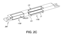
図2Cも、複数の曲がったべーパーチャンバ要素1100、特に2つの曲がったべーパーチャンバ要素1100を有するデバイスの実施形態を概略的に図示している。とりわけ、図示されている曲がったべーパーチャンバ要素1100の各々は、n個の曲げセクション131を有し、n=2である。とりわけ、この実施形態においては、曲がったべーパーチャンバ要素1100は、デバイスの、発熱要素が配置される領域に配設される。
Figure 2C also illustrates a schematic representation of an embodiment of a device having multiple curved
図3は、上記のデバイス200を含む光生成デバイス250を有する照明器具2の実施形態を概略的に図示している。参照符号300は、制御システム300、特にユーザインターフェースを有する制御システムを示している。制御システムは、特に、光生成デバイス250と機能的に結合され得る。図3は、光生成デバイス250を有するランプ1の実施形態も概略的に図示している。
Figure 3 illustrates diagrammatically an embodiment of a luminaire 2 with a light-generating
実施形態においては、デバイス200は、光生成デバイスを有してもよい。
In an embodiment,
更なる実施形態においては、デバイス200は、ドライバ231を含むドライバユニット230を有してもよく、ドライバ231は、曲がったべーパーチャンバ要素1100と熱的に結合される。
In a further embodiment, the
「複数」という用語は、2つ以上を指す。更に、「複数の」及び「多数の」という用語は、交換可能に使用され得る。 The term "plurality" refers to two or more. Additionally, the terms "multiple" and "multiple" may be used interchangeably.
本明細書における「実質的に」又は「本質的に」という用語、及び同様の用語は、当業者には理解されるだろう。「実質的に」又は「本質的に」という用語は、「全体的に」、「完全に」、「全て」などを備える実施形態も含み得る。従って、実施形態においては、「実質的に」又は「本質的に」という形容詞が取り除かれることもある。適用可能な場合には、「実質的に」という用語又は「本質的に」という用語は、100%を含む、95%以上、特に99%以上、更により特に99.5%以上などの、90%以上に関することもある。更に、「約」及び「ほぼ」という用語は、100%を含む、95%以上、特に99%以上、更により特に99.5%以上などの、90%以上に関することもある。数値の場合、「実質的に」、「本質的に」、「約」及び「ほぼ」という用語は、前記用語が参照する値の95%乃至105%、特に99%乃至101%などの、90%乃至110%の範囲に関することもあることを理解されるべきである。 The terms "substantially" or "essentially" and similar terms herein will be understood by those skilled in the art. The terms "substantially" or "essentially" may also include embodiments with "entirely", "completely", "all", etc. Thus, in embodiments, the adjective "substantially" or "essentially" may be omitted. Where applicable, the terms "substantially" or "essentially" may refer to 90% or more, such as 95% or more, particularly 99% or more, even more particularly 99.5% or more, including 100%. Furthermore, the terms "about" and "nearly" may refer to 90% or more, such as 95% or more, particularly 99% or more, even more particularly 99.5% or more, including 100%. In the case of numerical values, it should be understood that the terms "substantially", "essentially", "about" and "nearly" may also refer to a range of 90% to 110%, such as 95% to 105%, particularly 99% to 101%, of the value to which the term refers.
「有する」という用語は、「有する」という用語が「から成る」を意味する実施形態も含む。 The term "comprises" also includes embodiments in which the term "comprises" means "consists of."
「及び/又は」という用語は、特に、「及び/又は」の前及び後で言及されている項目のうちの1つ以上に関する。例えば、「項目1及び/又は項目2」という語句、及び同様の語句は、項目1及び項目2のうちの1つ以上に関し得る。「有する」という用語は、或る実施形態においては、「から成る」を指す場合があるが、別の実施形態においては、「少なくとも規定されている種を含み、随意に、1つ以上の他の種を含む」を指す場合もある。 The term "and/or" specifically refers to one or more of the items mentioned before and after "and/or." For example, the phrase "item 1 and/or item 2" and similar phrases can refer to one or more of items 1 and 2. The term "having" may refer in some embodiments to "consisting of," while in other embodiments it may refer to "including at least the specified species, and optionally one or more other species."
更に、明細書及び特許請求の範囲における、第1、第2、第3などの用語は、同様の要素を区別するために使用されるものであり、必ずしも、逐次的又は時間的な順序を説明するために使用されるものではない。そのように使用される用語は、適切な状況下で交換可能であり、本明細書において記載されている本発明の実施形態は、本明細書において記載又は図示されている順序以外の順序で動作が可能であることは理解されるべきである。 Furthermore, in the specification and claims, terms such as first, second, third, etc. are used to distinguish between similar elements and are not necessarily used to describe a sequential or chronological order. The terms so used are interchangeable under appropriate circumstances, and it should be understood that the embodiments of the invention described herein are capable of operation in orders other than those described or illustrated herein.
本明細書においては、とりわけ、動作中の、デバイス、装置、又はシステムが記載されているかもしれない。当業者には明らかであるだろうように、本発明は、動作の方法、又は動作中の、デバイス、装置、若しくはシステムに限定されるものではない。 The present specification may describe, among other things, devices, apparatus, or systems in operation. As will be apparent to one of ordinary skill in the art, the present invention is not limited to methods of operation or devices, apparatus, or systems in operation.
「更なる実施形態」という用語及び同様の用語は、前述の実施形態の特徴を有する実施形態を指すことがあるが、他の実施形態を指すこともある。 The term "further embodiments" and similar terms may refer to embodiments having features of the previously described embodiments, but may also refer to other embodiments.
上述の実施形態は、本発明を限定するものではなく、本発明を説明するものであり、当業者は、添付の特許請求の範囲の範囲から逸脱することなく、多くの他の実施形態を設計することができるだろうことに留意されたい。 It should be noted that the above-described embodiments are illustrative of the invention rather than limiting, and that a person skilled in the art could design many other embodiments without departing from the scope of the appended claims.
特許請求の範囲において、括弧内に配置される如何なる参照符号も、請求項を限定するものとして解釈されるべきではない。 In the claims, any reference signs placed between parentheses shall not be construed as limiting the claim.
「有する」という動詞及びその語形変化の使用は、請求項において示されている要素又はステップ以外の要素又はステップの存在を除外するものではない。文脈から明らかに別の意味が必要とされない限り、明細書及び特許請求の範囲全体を通して、「有する」、「有している」、「含む」、「含んでいる」、「含有する」、「含有している」などの単語は、排他的又は網羅的な意味とは対照的な、包括的な意味で、即ち、「含むが、これに限定されない」という意味で解釈されるべきである。 The use of the verb "have" and its conjugations does not exclude the presence of elements or steps other than those stated in a claim. Unless the context clearly requires otherwise, throughout the specification and claims, the words "have," "having," "include," "including," "containing," "containing" and the like are to be interpreted in an inclusive sense, i.e., "including but not limited to," as opposed to an exclusive or exhaustive sense.
要素の単数形表記は、このような要素の複数の存在を除外するものではない。 The singular reference of an element does not exclude the presence of a plurality of such elements.
本発明は、幾つかの別個の要素を有するハードウェアによって実施されてもよく、又は適切にプログラムされたコンピュータによって実施されてもよい。幾つかの手段を列挙している、デバイスの請求項、又は装置の請求項、又はシステムの請求項においては、これらの手段のうちの幾つかは、ハードウェアの全く同一のアイテムによって実施されてもよい。単に、或る特定の手段が、相互に異なる従属請求項において挙げられているという事実は、これらの手段の組み合わせは有利になるようには使用されることができないことを示すものではない。 The invention may be implemented by means of hardware comprising several distinct elements, or by means of a suitably programmed computer. In a device claim, or an apparatus claim or a system claim enumerating several means, several of these means may be embodied by one and the same item of hardware. The mere fact that certain means are recited in mutually different dependent claims does not indicate that a combination of these means cannot be used to advantage.
本発明は、デバイス、装置、若しくはシステムを制御し得る、又は本明細書において記載されている方法若しくはプロセスを実行し得る制御システムも提供する。更に他に、本発明は、デバイス、装置、又はシステムに機能的に結合される又は含まれるコンピュータにおいて実行するときに、このようなデバイス、装置、又はシステムの1つ以上の制御可能な要素を制御するコンピュータプログラム製品も提供する。 The invention also provides a control system that may control a device, apparatus, or system, or that may perform the methods or processes described herein. Additionally, the invention also provides a computer program product that, when executed on a computer operatively coupled to or included in a device, apparatus, or system, controls one or more controllable elements of such a device, apparatus, or system.
本発明は、更に、明細書において記載されている、及び/又は添付の図面において示されている、特徴付けている特徴のうちの1つ以上を有するデバイス、装置、又はシステムに当てはまる。本発明は、更に、明細書において記載されている、及び/又は添付の図面において示されている、特徴付けている特徴のうちの1つ以上を有する方法又はプロセスに関する。更に、方法又は方法の実施形態が、デバイス、装置、又はシステムにおいて実行されると記載されている場合には、デバイス、装置、又はシステムは、それぞれ、方法又は方法の実施形態(の実行)に適している、又はのために構成されていることは理解されるだろう。 The present invention further applies to a device, apparatus or system having one or more of the characterizing features described in the specification and/or shown in the accompanying drawings. The present invention further relates to a method or process having one or more of the characterizing features described in the specification and/or shown in the accompanying drawings. Furthermore, where a method or method embodiment is described as being performed in a device, apparatus or system, it will be understood that the device, apparatus or system is suitable for or configured for (performing) the method or method embodiment, respectively.
この特許において説明されている様々な態様は、更なる利点を提供するために組み合わされることができる。更に、当業者は、実施形態は組み合わされることができること、及び3つ以上の実施形態も組み合わされることができることを理解するだろう。更に、特徴のうちの幾つかは、1つ以上の分割出願のための基礎を形成することができる。 The various aspects described in this patent can be combined to provide additional advantages. Moreover, one skilled in the art will appreciate that the embodiments can be combined, and that more than two embodiments can be combined. Furthermore, some of the features can form the basis for one or more divisional applications.
Claims (15)
前記曲がったべーパーチャンバ要素を供給するよう、曲がっていない状態にある、請求項1乃至9のいずれか一項に記載のべーパーチャンバ要素を曲げるステップと、
前記曲がったべーパーチャンバ要素に冷却剤を注入するステップと、
前記曲がったべーパーチャンバ要素を封止するステップとを有する方法。 1. A method for providing a curved vapor chamber element, comprising:
- bending a vapor chamber element according to any one of claims 1 to 9 in an unbent state to provide said bent vapor chamber element;
injecting a coolant into the curved vapor chamber element;
and sealing the curved vapor chamber element.
Applications Claiming Priority (3)
| Application Number | Priority Date | Filing Date | Title |
|---|---|---|---|
| EP20174597 | 2020-05-14 | ||
| EP20174597.3 | 2020-05-14 | ||
| PCT/EP2021/061483 WO2021228590A1 (en) | 2020-05-14 | 2021-04-30 | Vapor chamber element |
Publications (2)
| Publication Number | Publication Date |
|---|---|
| JP2023526028A JP2023526028A (en) | 2023-06-20 |
| JP7463557B2 true JP7463557B2 (en) | 2024-04-08 |
Family
ID=70736666
Family Applications (1)
| Application Number | Title | Priority Date | Filing Date |
|---|---|---|---|
| JP2022568676A Active JP7463557B2 (en) | 2020-05-14 | 2021-04-30 | Vapor Chamber Element |
Country Status (5)
| Country | Link |
|---|---|
| US (1) | US11873982B2 (en) |
| EP (1) | EP4150281B1 (en) |
| JP (1) | JP7463557B2 (en) |
| CN (1) | CN115552189A (en) |
| WO (1) | WO2021228590A1 (en) |
Families Citing this family (1)
| Publication number | Priority date | Publication date | Assignee | Title |
|---|---|---|---|---|
| EP4327624A1 (en) * | 2021-04-23 | 2024-02-28 | Signify Holding B.V. | A vapor chamber |
Citations (2)
| Publication number | Priority date | Publication date | Assignee | Title |
|---|---|---|---|---|
| JP3192121U (en) | 2014-04-17 | 2014-07-31 | 奇▲こう▼科技股▲ふん▼有限公司 | Vapor chamber structure |
| US20190354148A1 (en) | 2018-05-17 | 2019-11-21 | Microsoft Technology Licensing, Llc | Conducting heat through a hinge |
Family Cites Families (15)
| Publication number | Priority date | Publication date | Assignee | Title |
|---|---|---|---|---|
| US20100175856A1 (en) | 2009-01-12 | 2010-07-15 | Meyer Iv George Anthony | Vapor chamber with wick structure of different thickness and die for forming the same |
| CN101825235A (en) * | 2009-03-05 | 2010-09-08 | 富准精密工业(深圳)有限公司 | Light-emitting diode lamp and light engine thereof |
| US7909489B2 (en) | 2009-03-09 | 2011-03-22 | Cpumate Inc | LED road lamp holder structure |
| ATE514036T1 (en) * | 2009-03-10 | 2011-07-15 | Cpumate Inc | LED STREET LAMP HOLDER STRUCTURE |
| CN101893401B (en) | 2009-05-19 | 2013-02-20 | 富准精密工业(深圳)有限公司 | Flat-plate heat pipe and manufacturing method thereof |
| US8506135B1 (en) | 2010-02-19 | 2013-08-13 | Xeralux, Inc. | LED light engine apparatus for luminaire retrofit |
| CN102345843A (en) * | 2010-07-30 | 2012-02-08 | 欧司朗有限公司 | Cooling device and LED (light emitting diode) illumination device with same |
| US20120294002A1 (en) * | 2011-05-18 | 2012-11-22 | Phoseon Technology, Inc. | Vapor chamber cooling of solid-state light fixtures |
| WO2013176355A1 (en) * | 2012-05-23 | 2013-11-28 | 주식회사 포스코엘이디 | Optical semiconductor illumination device |
| US9366484B2 (en) * | 2013-11-19 | 2016-06-14 | Shenzhen China Star Optoelectronics Technology Co., Ltd | Heat dissipation pipe loop and backlight module using same |
| TWI654404B (en) | 2017-05-05 | 2019-03-21 | 雙鴻科技股份有限公司 | Temperature plate |
| JP2019082264A (en) | 2017-10-27 | 2019-05-30 | 古河電気工業株式会社 | Vapor chamber |
| CN108119881A (en) * | 2017-12-19 | 2018-06-05 | 苏州亿拓光电科技有限公司 | LED component soaking plate and LED component with special-shaped capillary flow channel |
| JP6588599B1 (en) * | 2018-05-29 | 2019-10-09 | 古河電気工業株式会社 | Vapor chamber |
| TWI763989B (en) * | 2019-04-12 | 2022-05-11 | 雙鴻科技股份有限公司 | Flexible vapor chamber |
-
2021
- 2021-04-30 EP EP21723220.6A patent/EP4150281B1/en active Active
- 2021-04-30 JP JP2022568676A patent/JP7463557B2/en active Active
- 2021-04-30 WO PCT/EP2021/061483 patent/WO2021228590A1/en not_active Ceased
- 2021-04-30 CN CN202180034818.3A patent/CN115552189A/en active Pending
- 2021-04-30 US US17/925,047 patent/US11873982B2/en active Active
Patent Citations (2)
| Publication number | Priority date | Publication date | Assignee | Title |
|---|---|---|---|---|
| JP3192121U (en) | 2014-04-17 | 2014-07-31 | 奇▲こう▼科技股▲ふん▼有限公司 | Vapor chamber structure |
| US20190354148A1 (en) | 2018-05-17 | 2019-11-21 | Microsoft Technology Licensing, Llc | Conducting heat through a hinge |
Also Published As
| Publication number | Publication date |
|---|---|
| JP2023526028A (en) | 2023-06-20 |
| EP4150281B1 (en) | 2023-11-22 |
| WO2021228590A1 (en) | 2021-11-18 |
| EP4150281A1 (en) | 2023-03-22 |
| CN115552189A (en) | 2022-12-30 |
| US11873982B2 (en) | 2024-01-16 |
| US20230184422A1 (en) | 2023-06-15 |
Similar Documents
| Publication | Publication Date | Title |
|---|---|---|
| US12253314B2 (en) | Heat pipe | |
| TWI426859B (en) | Heat dissipation module, flat heat column thereof and manufacturing method for flat heat column | |
| US20120145357A1 (en) | Thin plate heat pipe | |
| TWM532046U (en) | Temperature equalization plate with liquid-vapor separation structure | |
| CN101893401B (en) | Flat-plate heat pipe and manufacturing method thereof | |
| EP3172489B1 (en) | Flexible coiled artery wick | |
| US20070022603A1 (en) | Vapor chamber and manufacturing method thereof | |
| US11873982B2 (en) | Vapor chamber element | |
| US12566032B2 (en) | Vapor chamber assembly | |
| US20240200765A1 (en) | A vapor chamber | |
| CN205980891U (en) | Vapor plate and its upper shell components | |
| US11585522B2 (en) | LED lighting device | |
| US11971160B2 (en) | Vapor chamber cooled high lumen device with improved cooling solution | |
| JP2009175523A (en) | Heat sink for thin LCD TV | |
| JP2023006705A (en) | Heat conductive member | |
| US11821615B2 (en) | System comprising luminescent material and two-phase cooling device | |
| JP2011247545A (en) | Method for manufacturing heat exchanger, the heat exchanger, and carburetor | |
| CN111386001A (en) | Vapor chamber with liquid tubes inside | |
| US20070079958A1 (en) | TriHEX (tm) heat exchanger | |
| KR20250042676A (en) | Heat dissipation apparatus | |
| JP2023006703A (en) | Heat conductive member | |
| JP2023006706A (en) | Heat conductive member |
Legal Events
| Date | Code | Title | Description |
|---|---|---|---|
| A621 | Written request for application examination |
Free format text: JAPANESE INTERMEDIATE CODE: A621 Effective date: 20230111 |
|
| A871 | Explanation of circumstances concerning accelerated examination |
Free format text: JAPANESE INTERMEDIATE CODE: A871 Effective date: 20230111 |
|
| A131 | Notification of reasons for refusal |
Free format text: JAPANESE INTERMEDIATE CODE: A131 Effective date: 20230621 |
|
| A601 | Written request for extension of time |
Free format text: JAPANESE INTERMEDIATE CODE: A601 Effective date: 20230914 |
|
| A521 | Request for written amendment filed |
Free format text: JAPANESE INTERMEDIATE CODE: A523 Effective date: 20231204 |
|
| TRDD | Decision of grant or rejection written | ||
| A01 | Written decision to grant a patent or to grant a registration (utility model) |
Free format text: JAPANESE INTERMEDIATE CODE: A01 Effective date: 20240306 |
|
| A61 | First payment of annual fees (during grant procedure) |
Free format text: JAPANESE INTERMEDIATE CODE: A61 Effective date: 20240327 |
|
| R150 | Certificate of patent or registration of utility model |
Ref document number: 7463557 Country of ref document: JP Free format text: JAPANESE INTERMEDIATE CODE: R150 |