JP7461827B2 - Damper Device - Google Patents
Damper Device Download PDFInfo
- Publication number
- JP7461827B2 JP7461827B2 JP2020134864A JP2020134864A JP7461827B2 JP 7461827 B2 JP7461827 B2 JP 7461827B2 JP 2020134864 A JP2020134864 A JP 2020134864A JP 2020134864 A JP2020134864 A JP 2020134864A JP 7461827 B2 JP7461827 B2 JP 7461827B2
- Authority
- JP
- Japan
- Prior art keywords
- elastic member
- state
- rotating body
- support
- disposed
- Prior art date
- Legal status (The legal status is an assumption and is not a legal conclusion. Google has not performed a legal analysis and makes no representation as to the accuracy of the status listed.)
- Active
Links
- 230000007935 neutral effect Effects 0.000 claims description 30
- 230000006835 compression Effects 0.000 claims description 28
- 238000007906 compression Methods 0.000 claims description 28
- 230000007704 transition Effects 0.000 claims description 11
- 230000004308 accommodation Effects 0.000 claims description 7
- 230000008878 coupling Effects 0.000 claims 1
- 238000010168 coupling process Methods 0.000 claims 1
- 238000005859 coupling reaction Methods 0.000 claims 1
- 238000010586 diagram Methods 0.000 description 12
- 230000002159 abnormal effect Effects 0.000 description 6
- 238000005452 bending Methods 0.000 description 3
- 230000007246 mechanism Effects 0.000 description 3
- 239000011347 resin Substances 0.000 description 3
- 229920005989 resin Polymers 0.000 description 3
- 210000000078 claw Anatomy 0.000 description 2
- 230000002093 peripheral effect Effects 0.000 description 2
- 230000004075 alteration Effects 0.000 description 1
- 230000005540 biological transmission Effects 0.000 description 1
- 239000002131 composite material Substances 0.000 description 1
- 239000000470 constituent Substances 0.000 description 1
- 238000013016 damping Methods 0.000 description 1
- 238000000034 method Methods 0.000 description 1
- 230000004048 modification Effects 0.000 description 1
- 238000012986 modification Methods 0.000 description 1
- 230000000149 penetrating effect Effects 0.000 description 1
- 230000008569 process Effects 0.000 description 1
Images


Classifications
-
- F—MECHANICAL ENGINEERING; LIGHTING; HEATING; WEAPONS; BLASTING
- F16—ENGINEERING ELEMENTS AND UNITS; GENERAL MEASURES FOR PRODUCING AND MAINTAINING EFFECTIVE FUNCTIONING OF MACHINES OR INSTALLATIONS; THERMAL INSULATION IN GENERAL
- F16F—SPRINGS; SHOCK-ABSORBERS; MEANS FOR DAMPING VIBRATION
- F16F15/00—Suppression of vibrations in systems; Means or arrangements for avoiding or reducing out-of-balance forces, e.g. due to motion
- F16F15/10—Suppression of vibrations in rotating systems by making use of members moving with the system
- F16F15/12—Suppression of vibrations in rotating systems by making use of members moving with the system using elastic members or friction-damping members, e.g. between a rotating shaft and a gyratory mass mounted thereon
- F16F15/121—Suppression of vibrations in rotating systems by making use of members moving with the system using elastic members or friction-damping members, e.g. between a rotating shaft and a gyratory mass mounted thereon using springs as elastic members, e.g. metallic springs
- F16F15/123—Wound springs
- F16F15/12353—Combinations of dampers, e.g. with multiple plates, multiple spring sets, i.e. complex configurations
- F16F15/1236—Combinations of dampers, e.g. with multiple plates, multiple spring sets, i.e. complex configurations resulting in a staged spring characteristic, e.g. with multiple intermediate plates
- F16F15/12366—Combinations of dampers, e.g. with multiple plates, multiple spring sets, i.e. complex configurations resulting in a staged spring characteristic, e.g. with multiple intermediate plates acting on multiple sets of springs
- F16F15/12373—Combinations of dampers, e.g. with multiple plates, multiple spring sets, i.e. complex configurations resulting in a staged spring characteristic, e.g. with multiple intermediate plates acting on multiple sets of springs the sets of springs being arranged at substantially the same radius
-
- F—MECHANICAL ENGINEERING; LIGHTING; HEATING; WEAPONS; BLASTING
- F16—ENGINEERING ELEMENTS AND UNITS; GENERAL MEASURES FOR PRODUCING AND MAINTAINING EFFECTIVE FUNCTIONING OF MACHINES OR INSTALLATIONS; THERMAL INSULATION IN GENERAL
- F16F—SPRINGS; SHOCK-ABSORBERS; MEANS FOR DAMPING VIBRATION
- F16F15/00—Suppression of vibrations in systems; Means or arrangements for avoiding or reducing out-of-balance forces, e.g. due to motion
- F16F15/10—Suppression of vibrations in rotating systems by making use of members moving with the system
- F16F15/12—Suppression of vibrations in rotating systems by making use of members moving with the system using elastic members or friction-damping members, e.g. between a rotating shaft and a gyratory mass mounted thereon
- F16F15/121—Suppression of vibrations in rotating systems by making use of members moving with the system using elastic members or friction-damping members, e.g. between a rotating shaft and a gyratory mass mounted thereon using springs as elastic members, e.g. metallic springs
- F16F15/127—Suppression of vibrations in rotating systems by making use of members moving with the system using elastic members or friction-damping members, e.g. between a rotating shaft and a gyratory mass mounted thereon using springs as elastic members, e.g. metallic springs using plastics springs combined with other types of springs
-
- F—MECHANICAL ENGINEERING; LIGHTING; HEATING; WEAPONS; BLASTING
- F16—ENGINEERING ELEMENTS AND UNITS; GENERAL MEASURES FOR PRODUCING AND MAINTAINING EFFECTIVE FUNCTIONING OF MACHINES OR INSTALLATIONS; THERMAL INSULATION IN GENERAL
- F16F—SPRINGS; SHOCK-ABSORBERS; MEANS FOR DAMPING VIBRATION
- F16F15/00—Suppression of vibrations in systems; Means or arrangements for avoiding or reducing out-of-balance forces, e.g. due to motion
- F16F15/10—Suppression of vibrations in rotating systems by making use of members moving with the system
- F16F15/12—Suppression of vibrations in rotating systems by making use of members moving with the system using elastic members or friction-damping members, e.g. between a rotating shaft and a gyratory mass mounted thereon
- F16F15/131—Suppression of vibrations in rotating systems by making use of members moving with the system using elastic members or friction-damping members, e.g. between a rotating shaft and a gyratory mass mounted thereon the rotating system comprising two or more gyratory masses
-
- F—MECHANICAL ENGINEERING; LIGHTING; HEATING; WEAPONS; BLASTING
- F16—ENGINEERING ELEMENTS AND UNITS; GENERAL MEASURES FOR PRODUCING AND MAINTAINING EFFECTIVE FUNCTIONING OF MACHINES OR INSTALLATIONS; THERMAL INSULATION IN GENERAL
- F16F—SPRINGS; SHOCK-ABSORBERS; MEANS FOR DAMPING VIBRATION
- F16F15/00—Suppression of vibrations in systems; Means or arrangements for avoiding or reducing out-of-balance forces, e.g. due to motion
- F16F15/10—Suppression of vibrations in rotating systems by making use of members moving with the system
- F16F15/12—Suppression of vibrations in rotating systems by making use of members moving with the system using elastic members or friction-damping members, e.g. between a rotating shaft and a gyratory mass mounted thereon
- F16F15/121—Suppression of vibrations in rotating systems by making use of members moving with the system using elastic members or friction-damping members, e.g. between a rotating shaft and a gyratory mass mounted thereon using springs as elastic members, e.g. metallic springs
- F16F15/123—Wound springs
- F16F15/12313—Wound springs characterised by the dimension or shape of spring-containing windows
-
- F—MECHANICAL ENGINEERING; LIGHTING; HEATING; WEAPONS; BLASTING
- F16—ENGINEERING ELEMENTS AND UNITS; GENERAL MEASURES FOR PRODUCING AND MAINTAINING EFFECTIVE FUNCTIONING OF MACHINES OR INSTALLATIONS; THERMAL INSULATION IN GENERAL
- F16F—SPRINGS; SHOCK-ABSORBERS; MEANS FOR DAMPING VIBRATION
- F16F15/00—Suppression of vibrations in systems; Means or arrangements for avoiding or reducing out-of-balance forces, e.g. due to motion
- F16F15/10—Suppression of vibrations in rotating systems by making use of members moving with the system
- F16F15/12—Suppression of vibrations in rotating systems by making use of members moving with the system using elastic members or friction-damping members, e.g. between a rotating shaft and a gyratory mass mounted thereon
- F16F15/121—Suppression of vibrations in rotating systems by making use of members moving with the system using elastic members or friction-damping members, e.g. between a rotating shaft and a gyratory mass mounted thereon using springs as elastic members, e.g. metallic springs
- F16F15/123—Wound springs
- F16F15/1232—Wound springs characterised by the spring mounting
-
- F—MECHANICAL ENGINEERING; LIGHTING; HEATING; WEAPONS; BLASTING
- F16—ENGINEERING ELEMENTS AND UNITS; GENERAL MEASURES FOR PRODUCING AND MAINTAINING EFFECTIVE FUNCTIONING OF MACHINES OR INSTALLATIONS; THERMAL INSULATION IN GENERAL
- F16F—SPRINGS; SHOCK-ABSORBERS; MEANS FOR DAMPING VIBRATION
- F16F15/00—Suppression of vibrations in systems; Means or arrangements for avoiding or reducing out-of-balance forces, e.g. due to motion
- F16F15/10—Suppression of vibrations in rotating systems by making use of members moving with the system
- F16F15/12—Suppression of vibrations in rotating systems by making use of members moving with the system using elastic members or friction-damping members, e.g. between a rotating shaft and a gyratory mass mounted thereon
- F16F15/121—Suppression of vibrations in rotating systems by making use of members moving with the system using elastic members or friction-damping members, e.g. between a rotating shaft and a gyratory mass mounted thereon using springs as elastic members, e.g. metallic springs
- F16F15/123—Wound springs
- F16F15/12353—Combinations of dampers, e.g. with multiple plates, multiple spring sets, i.e. complex configurations
- F16F15/1236—Combinations of dampers, e.g. with multiple plates, multiple spring sets, i.e. complex configurations resulting in a staged spring characteristic, e.g. with multiple intermediate plates
- F16F15/12366—Combinations of dampers, e.g. with multiple plates, multiple spring sets, i.e. complex configurations resulting in a staged spring characteristic, e.g. with multiple intermediate plates acting on multiple sets of springs
-
- F—MECHANICAL ENGINEERING; LIGHTING; HEATING; WEAPONS; BLASTING
- F16—ENGINEERING ELEMENTS AND UNITS; GENERAL MEASURES FOR PRODUCING AND MAINTAINING EFFECTIVE FUNCTIONING OF MACHINES OR INSTALLATIONS; THERMAL INSULATION IN GENERAL
- F16D—COUPLINGS FOR TRANSMITTING ROTATION; CLUTCHES; BRAKES
- F16D7/00—Slip couplings, e.g. slipping on overload, for absorbing shock
- F16D7/02—Slip couplings, e.g. slipping on overload, for absorbing shock of the friction type
- F16D7/024—Slip couplings, e.g. slipping on overload, for absorbing shock of the friction type with axially applied torque limiting friction surfaces
- F16D7/025—Slip couplings, e.g. slipping on overload, for absorbing shock of the friction type with axially applied torque limiting friction surfaces with flat clutching surfaces, e.g. discs
Description
本発明はダンパ装置に関する。 The present invention relates to a damper device.
一般に車輌の異音及び振動には、アイドリング時の異音、走行時の異音、及びティップイン・ティップアウト(低周波振動)がある。これらの異音や振動を抑制するためにダンパ装置が設けられている。 Typically, abnormal noises and vibrations in vehicles include abnormal noises while idling, abnormal noises while driving, and tip-in/tip-out (low-frequency vibration). Damper devices are provided to suppress these abnormal noises and vibrations.
アイドリング時の異音に対しては、ダンパ装置の捩り特性において低捩り角度領域が関連しており、そこでの捩り剛性は低い方が好ましい。一方、ティップイン・ティップアウトに対しては、捩り特性をできるだけ高剛性にする必要がある。 Regarding abnormal noise during idling, the low torsional angle region in the torsional characteristics of the damper device is related, and low torsional rigidity there is preferable. On the other hand, for tip-in and tip-out, the torsional characteristics need to be as rigid as possible.
そこで、特許文献1及び特許文献2に示されるように、捩り特性を多段化したダンパ装置が提供されている。これらの文献に示された装置では、捩り特性の1段目(低捩り角度領域)における捩り剛性を低く抑えることによって、アイドリング時の異音を抑えている。また、捩り特性の2段目(高捩り角度領域)では捩り剛性を高く設定し、ティップイン・ティップアウトの振動を減衰するようにしている。
As a result, damper devices with multi-stage torsional characteristics have been provided, as shown in
以上の特許文献に示されたダンパ装置では、出力側の部材であるスプラインハブが、筒状のハブと、ハブの外周側に設けられたフランジと、に分離され、分離されたハブとフランジとの間に、サブダンパユニットが設けられている。 In the damper devices shown in the above patent documents, the splined hub, which is the output member, is separated into a cylindrical hub and a flange provided on the outer periphery of the hub, and a sub-damper unit is provided between the separated hub and the flange.
このような従来の多段化されたダンパ装置では、部品点数が増加し、また装置の小型化の妨げになっている。 In such conventional multi-stage damper devices, the number of parts increases and this hinders the miniaturization of the device.
本発明の課題は、ダンパ装置の捩り特性を、簡単な構成で多段化することにある。 The objective of the present invention is to provide a multi-stage torsional characteristic for a damper device with a simple configuration.
(1)本発明に係るダンパ装置は、それぞれ回転軸の回りに回転する第1回転体及び第2回転体と、弾性連結部と、を備えている。第2回転体は、第1回転体と相対回転可能に配置されている。弾性連結部は、第1回転体と第2回転体との間の相対回転による捩れがない中立状態において予め圧縮されて配置された第1弾性部材及び第2弾性部材を有し、第1回転体と第2回転体とを回転方向に弾性的に連結する。 (1) The damper device according to the present invention comprises a first rotating body and a second rotating body that each rotate around a rotation axis, and an elastic connecting part. The second rotating body is arranged so as to be rotatable relative to the first rotating body. The elastic connecting part has a first elastic member and a second elastic member that are arranged in advance compressed in a neutral state in which there is no twisting due to relative rotation between the first rotating body and the second rotating body, and elastically connects the first rotating body and the second rotating body in the rotational direction.
第1弾性部材は、第1回転体が第2回転体に対して中立状態から第1回転方向に捩れる際に、圧縮状態から自由状態を経てさらに圧縮される。また、第2弾性部材は、第1回転体が第2回転体に対して中立状態から第2回転方向に捩れる際に、圧縮状態から自由状態を経てさらに圧縮される。そして、第1弾性部材及び第2弾性部材は、圧縮作動時において円周方向の端面が片当たり状態から両当たり状態に移行する。 When the first rotating body twists from a neutral state in the first rotational direction relative to the second rotating body, the first elastic member goes from a compressed state through a free state and is then further compressed. Also, when the first rotating body twists from a neutral state in the second rotational direction relative to the second rotating body, the second elastic member goes from a compressed state through a free state and is then further compressed. And, during the compression operation, the circumferential end faces of the first elastic member and the second elastic member transition from a one-sided contact state to a two-sided contact state.
なお、ここでの「自由状態」とは、各弾性部材が圧縮又は伸長されていない自由長になっている状態である。また、「片当たり状態」とは、弾性部材の円周方向の端面が、第1回転体及び/又は第2回転体に対して、径方向内側又は外側の片側のみに当接している状態を意味し、「両当たり状態」とは、弾性部材の円周方向の端面が、第1回転体及び/又は第2回転体に対して、径方向の内側及び外側の両方に当接している状態を意味する。 The "free state" here means that each elastic member is in a free length and is not compressed or stretched. The "one-sided contact state" means that the circumferential end face of the elastic member is in contact with only one of the radially inner or outer sides of the first rotating body and/or the second rotating body, and the "double contact state" means that the circumferential end face of the elastic member is in contact with both the radially inner and outer sides of the first rotating body and/or the second rotating body.
このダンパ装置では、中立状態では、圧縮された状態で配置されている第1弾性部材及び第2弾性部によって、第1回転体及び第2回転体は、第1回転方向及び第2回転方向のいずれの方向にも捩りトルクを受けている。すなわち、中立状態における第1弾性部材及び第2弾性部材による捩りトルクは逆である。したがって、各弾性部材による捩り特性は、特性図の縦方向(トルク方向)においてずれている。 In this damper device, in the neutral state, the first rotating body and the second rotating body receive torsional torque in both the first and second rotation directions due to the first elastic member and the second elastic portion, which are arranged in a compressed state. In other words, the torsional torques due to the first elastic member and the second elastic member in the neutral state are opposite. Therefore, the torsional characteristics due to each elastic member are shifted in the vertical direction (torque direction) of the characteristic diagram.
また、第1弾性部材及び第2弾性部材は、圧縮作動時において両端面が片当たり状態から両当たり状態に移行する。したがって、各弾性部材が片当たり状態で圧縮される場合は、比較的低剛性であり、片当たり状態から両当り状態に移行すると、低剛性から高剛性になる。したがって、弾性部材において、片当たり状態から両当り状態への移行タイミングをずらすと、捩り特性における屈曲点(捩り剛性が変化する点)は、特性図の横方向(捩り角度方向)にずれることになる。 In addition, both end faces of the first elastic member and the second elastic member transition from a single contact state to a double contact state during compression. Therefore, when each elastic member is compressed in a single contact state, it has a relatively low rigidity, and when it transitions from a single contact state to a double contact state, it changes from low rigidity to high rigidity. Therefore, if the timing of the transition from a single contact state to a double contact state in the elastic member is shifted, the bending point in the torsional characteristics (the point where the torsional rigidity changes) will shift horizontally (in the torsional angle direction) on the characteristic diagram.
以上のような、第1弾性部材と第2弾性部材の捩り特性のトルク方向のずれと、捩り角度方向のずれと、を適宜設定することによって、第1弾性部材と第2弾性部材の合成捩り特性を2段あるいは3段にすることが可能になる。このため、簡単な構成で捩り特性の多段化が可能になる。 By appropriately setting the deviation in the torque direction and the deviation in the torsion angle direction of the torsion characteristics of the first elastic member and the second elastic member as described above, it is possible to make the composite torsion characteristics of the first elastic member and the second elastic member into two or three stages. Therefore, it is possible to make the torsion characteristics multi-staged with a simple structure.
さらに、このダンパ装置において、中立状態では、圧縮された状態で配置されている第1弾性部材及び第2弾性部によって、第1回転体及び第2回転体は、第1回転方向及び第2回転方向のいずれの方向にも捩りトルクを受けている。したがって、圧縮された弾性部材によって発生される捩りトルク以下のトルク変動が入力されても、第1回転体と第2回転体との捩り角度(相対回転)は小さく抑えられる。このため、所定の捩り角度範囲では、トルク変動による各部材間の衝突音を抑えることができる。 Furthermore, in this damper device, in the neutral state, the first rotating body and the second rotating body receive torsional torque in both the first rotation direction and the second rotation direction due to the first elastic member and the second elastic portion arranged in a compressed state. Therefore, even if a torque fluctuation equal to or less than the torsional torque generated by the compressed elastic member is input, the torsional angle (relative rotation) between the first rotating body and the second rotating body is kept small. Therefore, within a predetermined torsional angle range, it is possible to suppress the collision noise between the members due to the torque fluctuation.
(2)好ましくは、第1弾性部材は、第1回転体が第2回転体に対して中立状態から第2回転方向に捩れる際に、圧縮状態からさらに圧縮される。また、第2弾性部材は、第1回転体が第2回転体に対して中立状態から第1回転方向に捩れる際に、圧縮状態からさらに圧縮される。 (2) Preferably, the first elastic member is further compressed from the compressed state when the first rotating body is twisted from the neutral state in the second rotational direction relative to the second rotating body. Also, the second elastic member is further compressed from the compressed state when the first rotating body is twisted from the neutral state in the first rotational direction relative to the second rotating body.
(3)好ましくは、第1弾性部材及び第2弾性部材は、同じ剛性を有する。 (3) Preferably, the first elastic member and the second elastic member have the same rigidity.
(4)好ましくは、第1回転体は、第1支持部及び第2支持部を有している。また、第2回転体は、第1収容部及び第2収容部を有している。第1収容部は、第1支持部に対して軸方向視で一部が重なるようにかつ第1回転方向側にオフセットして配置されている。第2収容部は、第2支持部に対して軸方向視で一部が重なるようにかつ第2回転方向側にオフセットして配置されている。そして、この場合、第1弾性部材は、第1支持部及び第1収容部に配置されている。また、第2弾性部材は、第2支持部及び第2収容部に配置され、第1弾性部材と並列で作動する。 (4) Preferably, the first rotating body has a first support portion and a second support portion. The second rotating body has a first storage portion and a second storage portion. The first storage portion is arranged so as to overlap with the first support portion in an axial view and to be offset toward the first rotation direction side. The second storage portion is arranged so as to overlap with the second support portion in an axial view and to be offset toward the second rotation direction side. In this case, the first elastic member is arranged in the first support portion and the first storage portion. The second elastic member is arranged in the second support portion and the second storage portion, and operates in parallel with the first elastic member.
(5)好ましくは、第1支持部及び第2支持部のそれぞれは、第1回転方向側の端部に第1支持面を、第2回転方向側の端部に第2支持面を有している。また、第1収容部及び第2収容部は、第1回転方向側の端部に第1収容面を、第2回転方向側の端部に第2収容面を有している。この場合、第1弾性部材は、第1支持面と第2収容面との間に圧縮して配置され、第2弾性部材は、第1収容面と第2支持面との間に圧縮して配置されている。また、好ましくは、第1支持面及び第1収容面の少なくともいずれか一方と、第2支持面及び第2収容面の少なくとも一方とは、径方向外方に開くように傾斜している。 (5) Preferably, each of the first support portion and the second support portion has a first support surface at an end portion on the first rotation direction side and a second support surface at an end portion on the second rotation direction side. Also, each of the first storage portion and the second storage portion has a first storage surface at an end portion on the first rotation direction side and a second storage surface at an end portion on the second rotation direction side. In this case, the first elastic member is arranged in a compressed state between the first support surface and the second storage surface, and the second elastic member is arranged in a compressed state between the first storage surface and the second support surface. Also, preferably, at least one of the first support surface and the first storage surface and at least one of the second support surface and the second storage surface are inclined so as to open outward in the radial direction.
各弾性部材が配置されている支持面及び収容面の少なくとも一方を、径方向外方に開くように傾斜することによって、各弾性部材の圧縮作動時に、各弾性部材を片当たり状態から両当たり状態に移行させることができる。 By inclining at least one of the support surface and the storage surface on which each elastic member is arranged so that it opens outward in the radial direction, each elastic member can be transitioned from a single contact state to a double contact state when the elastic member is compressed.
(6)好ましくは、弾性連結部は、第3弾性部材及び第4弾性部材とさらに有している。第3弾性部材及び第4弾性部材は、中立状態において予め圧縮されて配置されている。また、第3弾性部材は、第1回転体が第2回転体に対して中立状態から第1回転方向に捩れる際に、圧縮状態から自由状態を経てさらに圧縮される。第4弾性部材は、第1回転体が第2回転体に対して中立状態から第2回転方向に捩れる際に、圧縮状態から自由状態を経てさらに圧縮される。そして、第3弾性部材及び第4弾性部材は、圧縮作動時において両端面が片当たり状態から両当たり状態に移行する。 (6) Preferably, the elastic connecting portion further includes a third elastic member and a fourth elastic member. The third elastic member and the fourth elastic member are arranged in a pre-compressed state in a neutral state. Furthermore, when the first rotating body twists from the neutral state in the first rotational direction relative to the second rotating body, the third elastic member is further compressed through a compressed state and a free state. When the first rotating body twists from the neutral state in the second rotational direction relative to the second rotating body, the fourth elastic member is further compressed through a compressed state and a free state. Furthermore, the third elastic member and the fourth elastic member transition from a one-side contact state to a two-side contact state at both end faces during compression operation.
(7)好ましくは、第1回転体は、第3支持部及び第4支持部をさらに有している。第3支持部は、回転軸を挟んで第1支持部と対向して配置されている。第4支持部は、回転軸を挟んで第2支持部と対向して配置されている。また、好ましくは、第2回転体は、第3収容部及び第4収容部をさらに有している。第3収容部は、回転軸を挟んで第1収容部と対向して配置されている。第4収容部は、回転軸を挟んで第2収容部と対向して配置されている。そして、第3収容部は、第3支持部に対して軸方向視で一部が重なるようにかつ第1回転方向側にオフセットして配置されている。第4収容部は、第4支持部に対して軸方向視で一部が重なるようにかつ第2回転方向側にオフセットして配置されている。 (7) Preferably, the first rotating body further has a third support section and a fourth support section. The third support section is disposed opposite the first support section across the rotation axis. The fourth support section is disposed opposite the second support section across the rotation axis. Also, preferably, the second rotating body further has a third storage section and a fourth storage section. The third storage section is disposed opposite the first storage section across the rotation axis. The fourth storage section is disposed opposite the second storage section across the rotation axis. The third storage section is disposed so as to overlap with the third support section in the axial direction and offset toward the first rotation direction. The fourth storage section is disposed so as to overlap with the fourth support section in the axial direction and offset toward the second rotation direction.
そして、この場合、第3弾性部材は、第3支持部及び第3収容部に配置されている。また、第4弾性部材は、第4支持部及び第4収容部に配置され、第3弾性部材と並列で作動する。 In this case, the third elastic member is disposed in the third support portion and the third housing portion. The fourth elastic member is disposed in the fourth support portion and the fourth housing portion, and operates in parallel with the third elastic member.
(8)好ましくは、第3支持部及び第4支持部のそれぞれは、第1回転方向側の端部に第3支持面を、第2回転方向側の端部に第4支持面を有している。また、第3収容部及び第4収容部は、第1回転方向側の端部に第3収容面を、第2回転方向側の端部に第4収容面を有している。この場合、第3弾性部材は、第3支持面と第4収容面との間に圧縮して配置されている。また、第4弾性部材は、第3収容面と第4支持面との間に圧縮して配置されている。そして、第3支持面及び第3収容面の少なくともいずれか一方と、第4支持面及び第4収容面の少なくとも一方とは、径方向外方に開くように傾斜している。 (8) Preferably, each of the third support portion and the fourth support portion has a third support surface at an end portion on the first rotation direction side and a fourth support surface at an end portion on the second rotation direction side. Also, each of the third housing portion and the fourth housing portion has a third housing surface at an end portion on the first rotation direction side and a fourth housing surface at an end portion on the second rotation direction side. In this case, the third elastic member is disposed in a compressed state between the third support surface and the fourth housing surface. Also, the fourth elastic member is disposed in a compressed state between the third housing surface and the fourth support surface. And, at least one of the third support surface and the third housing surface and at least one of the fourth support surface and the fourth housing surface are inclined so as to open outward in the radial direction.
(9)好ましくは、第1収容部は第1支持部に対して第1回転方向側に所定角度オフセットして配置されるとともに、第2収容部は第2支持部に対して第2回転方向側に所定角度オフセットして配置されている。この場合、第1捩り角度領域では、第1弾性部材及び第2弾性部材は片当たり状態である。また、第1捩り角度領域より大きい第2捩り角度領域では、第1弾性部材は片当たり状態であり、かつ第2弾性部材は両当たり状態である。さらに、第2捩り角度領域を超えた第3捩り角度領域では、第1弾性部材及び第2弾性部材は両当たり状態である。 (9) Preferably, the first housing portion is disposed offset by a predetermined angle in the first rotation direction relative to the first support portion, and the second housing portion is disposed offset by a predetermined angle in the second rotation direction relative to the second support portion. In this case, in the first torsion angle region, the first elastic member and the second elastic member are in a one-sided contact state. Also, in a second torsion angle region larger than the first torsion angle region, the first elastic member is in a one-sided contact state, and the second elastic member is in a two-sided contact state. Furthermore, in a third torsion angle region beyond the second torsion angle region, the first elastic member and the second elastic member are in a two-sided contact state.
(10)好ましくは、第1収容部は第1支持部に対して第1回転方向側に所定角度オフセットして配置されるとともに、第2収容部は第2支持部に対して第2回転方向側に所定角度オフセットして配置されている。この場合、第1捩り角度領域では、第1弾性部材は片当たり状態であり、かつ第2弾性部材は両当たり状態である。また、第1捩り角度領域を超えた第2捩り角度領域では、第1弾性部材は及び第2弾性部材は両当たり状態である。 (10) Preferably, the first housing portion is disposed offset by a predetermined angle in the first rotation direction relative to the first support portion, and the second housing portion is disposed offset by a predetermined angle in the second rotation direction relative to the second support portion. In this case, in the first torsion angle region, the first elastic member is in a one-sided contact state, and the second elastic member is in a two-sided contact state. In addition, in a second torsion angle region beyond the first torsion angle region, the first elastic member and the second elastic member are in a two-sided contact state.
(11)好ましくは、第1収容部は第1支持部に対して第1回転方向側に所定角度オフセットして配置されるとともに、第2収容部は第2支持部に対して第2回転方向側に所定角度オフセットして配置されている。この場合、第1捩り角度領域では、第1弾性部材及び第2弾性部材は両当たり状態である。また、第1捩り角度領域より大きい第2捩り角度領域では、第1弾性部材は片当たり状態であり、かつ第2弾性部材は両当たり状態である。さらに、第2捩り角度領域を超えた第3捩り角度領域では、第1弾性部材及び第2弾性部材は両当たり状態である。 (11) Preferably, the first housing portion is disposed offset by a predetermined angle in the first rotation direction relative to the first support portion, and the second housing portion is disposed offset by a predetermined angle in the second rotation direction relative to the second support portion. In this case, in the first torsion angle region, the first elastic member and the second elastic member are in a double contact state. Also, in a second torsion angle region larger than the first torsion angle region, the first elastic member is in a single contact state, and the second elastic member is in a double contact state. Furthermore, in a third torsion angle region beyond the second torsion angle region, the first elastic member and the second elastic member are in a double contact state.
以上のような本発明では、簡単な構成でダンパ装置の捩り特性を多段化することができる。 As described above, the present invention allows the torsional characteristics of the damper device to be multi-staged with a simple configuration.
-第1実施形態- --First embodiment--
[全体構成]
図1は、本発明の一実施形態によるトルクリミッタ付きダンパ装置1(以下、単に「ダンパ装置」と記載する)の断面図である。また、図2はダンパ装置1の正面図であり、その一部は構成する部材を取り外して示している。図1においては、ダンパ装置1の左側にエンジン(図示せず)が配置され、右側に電動機や変速装置等を含む駆動ユニット(図示せず)が配置されている。
[overall structure]
Fig. 1 is a cross-sectional view of a
なお、以下の説明において、軸方向とは、ダンパ装置1の回転軸Oが延びる方向である。また、円周方向とは、回転軸Oを中心とした円の円周方向であり、径方向とは、回転軸Oを中心とした円の径方向である。なお、円周方向とは、回転軸Oを中心とした円の円周方向に完全に一致している必要はない。また、径方向とは、回転軸Oを中心とした円の直径方向に完全に一致している必要はない。
In the following description, the axial direction is the direction in which the rotation axis O of the
このダンパ装置1は、フライホイール(図示せず)と駆動ユニットの入力軸との間に設けられ、エンジンと駆動ユニットとの間で伝達されるトルクを制限するとともに、回転変動を減衰するための装置である。ダンパ装置1は、トルクリミッタユニット10と、ダンパユニット20と、を有している。
This
[トルクリミッタユニット10]
トルクリミッタユニット10は、ダンパユニット20の外周側に配置されている。トルクリミッタユニット10は、フライホイールとダンパユニット20との間で伝達されるトルクを制限する。トルクリミッタユニット10は、カバープレート11と、支持プレート12と、摩擦ディスク13と、プレッシャプレート14と、コーンスプリング15と、を有している。
[Torque limiter unit 10]
The
カバープレート11と支持プレート12とは、軸方向の所定の間隔をあけて配置されており、両プレート11,12の外周部が、複数のボルト16によってフライホイールに固定されている。
The
摩擦ディスク13、プレッシャプレート14、及びコーンスプリング15は、カバープレート11と支持プレート12との軸方向間に配置されている。
The
摩擦ディスク13は、コアプレート及びコアプレートの両側面に固定された1対の摩擦部材を有している。そして、摩擦ディスク13の内周部が、複数のリベット17によってダンパユニット20に固定されている。プレッシャプレート14及びコーンスプリング15は、摩擦ディスク13と支持プレート12との間に配置されている。
The
プレッシャプレート14は、環状に形成され、摩擦ディスク13の支持プレート12側に配置されている。なお、プレッシャプレート14の外周部には、複数の爪14aが形成されており、この爪14aが支持プレート12に形成された複数の係合孔12aに係合している。
The
コーンスプリング15は、プレッシャプレート14と支持プレート12との間に配置されている。コーンスプリング15は、プレッシャプレート14を介して摩擦ディスク13をカバープレート11に押圧している。
The
[ダンパユニット20]
ダンパユニット20は、入力側プレート30(第1回転体の一例)と、ハブフランジ40(第2回転体の一例)と、弾性連結部50と、ヒス発生機構60と、を有している。
[Damper unit 20]
The
<入力側プレート30>
入力側プレート30は、第1プレート31及び第2プレート32を有している。第1プレート31及び第2プレート32は、中心部に孔を有する円板状に形成され、互いに軸方向に間隔をあけて配置されている。第1プレート31は、外周部にそれぞれ4個のストッパ部31a及び固定部31bを有している。また、第1プレート31及び第2プレート32は、それぞれ1対の第1支持部301及び1対の第2支持部302を有している。第1プレート31及び第2プレート32において、第1支持部301及び第2支持部302は同じ位置に形成されている。また、第1プレート31には、リベット17に対応する位置に組付用の孔32aが形成されている。
<
The
ストッパ部31aは、第1プレート31の外周部を第2プレート32側に折り曲げて形成され、軸方向に延びている。固定部31bは、ストッパ部31aの先端を径方向外方に折り曲げて形成されている。この固定部31bが、第2プレート32の外周端部に複数のリベット33によって固定されている。このため、第1プレート31と第2プレート32とは、互いに相対回転不能であり、互いに軸方向に移動不能である。
The
1対の第1支持部301は回転軸Oを挟んで対向して配置されている。また、1対の第2支持部302は、第1支持部と90°の間隔をあけて、回転軸Oを挟んで対向して配置されている。各支持部301,302は、軸方向に貫通する孔と、この孔の内周縁及び外周縁に切り起こされた縁部と、を有している。
The pair of
図3に模式的に示すように、各支持部301,302は、第1回転方向側(以下、単に「R1側」と記載する)の端部にR1支持面301a,302aを有し、第2回転方向側(以下、単に「R2側」と記載する)の端部にR2支持面301b,302bを有している。各支持部301,302における孔の幅(R1支持面とR2支持面との間の距離)はLである。各支持面301a,301b,302a,302bは径方向外方に向かって開くように傾斜しているが、詳細は後述する。
As shown in FIG. 3, each
なお、図3では、第1支持部301及び第2支持部302を実線で示し、後述するハブフランジ40の第1収容部401及び第2収容部402を一点鎖線で示している。また、図3は模式図であって、図2で示す実際の具体的な形状とは異なっている。
In FIG. 3, the
<ハブフランジ40>
図1及び図2に示すように、ハブフランジ40は、ハブ41と、フランジ42と、を有している。ハブフランジ40は、入力側プレート30に対して所定の角度範囲で相対回転可能である。ハブ41は、筒状に形成され、中心部にはスプライン孔41aが形成されている。また、ハブ41は第1プレート31及び第2プレート32の中心部の孔を貫通している。フランジ42は、中心部に孔を有する円板状に形成され、ハブ41の径方向外方に配置されている。フランジ42は、第1プレート31と第2プレート32との軸方向間に配置されている。
<
As shown in Figures 1 and 2, the
図2に示すように、ハブ41の外周面には複数の外歯41bが形成され、フランジ42の内周面には、ハブ41の外歯41bに噛み合う複数の内歯42aが形成されている。したがって、ハブ41とフランジ42とは一体で回転する。なお、この実施形態では、ハブ41とフランジ42とを別体で構成しているが、これらを1つの部材で構成してもよい。
As shown in FIG. 2, a plurality of
フランジ42は、4つのストッパ用突起42bと、それぞれ1対の第1収容部401及び第2収容部402と、4つの切欠403と、を有している。
The
4つのストッパ用突起42bは、フランジ42の外周面から径方向外方に突出して形成されている。各ストッパ用突起42bが形成された位置は、各収容部401,402の円周方向の中央部の径方向外方である。そして、入力側プレート30とハブフランジ40とが互いに相対回転した際に、ストッパ用突起42bが第1プレート31のストッパ部31aに当接することにより、入力側プレート30とハブフランジ40との相対回転が禁止される。
The four
図3Aに示すように、1対の第1収容部401は、1対の第1支持部301に対応する位置に配置されている。また、1対の第2収容部402は、1対の第2支持部302に対応する位置に配置されている。より詳細には、入力側プレート30とハブフランジ40との間の相対回転角度が0°であって両者が捩じれていない中立状態(捩り角度0°)では、1対の第1収容部401は、第1支持部301に対して軸方向視で一部が重なるようにかつR1側に角度θ1(例えば2°)だけオフセットして配置されている。また、第2収容部402は、第2支持部302に対して軸方向視で一部が重なるようにかつR2側に角度θ1だけオフセットして配置されている。
As shown in FIG. 3A, the pair of
各収容部401,402は、外周部が円弧状のほぼ矩形の孔である。図3Aに示すように、各収容部401,402は、R1側の端部にR1収容面401a,402aを有し、R2側の端部にR2収容面401b,402bを有している。各収容部401,402の孔の幅(R1収容面401a,402aと、R2収容面401b,402bと、の間の距離)は、各支持部301,302の孔の幅と同様にLに設定されている。各収容面401a,401b,402a,402bは径方向外方に向かって開くように傾斜しているが、詳細は後述する。
Each of the
4つの切欠403は、隣接する収容部401,402の円周方向間において、フランジ42の外周面から径方向内方に所定の深さで形成されている。各切欠403が形成された位置は、トルクリミッタユニット10の摩擦ディスク13と第1プレート31とを連結するリベット17の位置に対応している。したがって、それぞれ別工程で組み立てられたトルクリミッタユニット10及びダンパユニット20を、第2プレート32の組付用孔32a及びフランジ42の切欠403を利用して、リベット17により固定することが可能である。
The four
<弾性連結部50>
弾性連結部50は、4個のコイルスプリング51(第1弾性部材及び第2弾性部材の一例)と、4個の樹脂部材52と、を有している。各コイルスプリング51は、外スプリング及び内スプリングを有している。4個のコイルスプリング51は、フランジ42の各収容部401,402に収容され、入力側プレート30の各支持部301,302によって径方向及び軸方向に支持されている。これらのコイルスプリング51は並列で作動する。
<
The elastic connecting
また、4個のコイルスプリング51の自由長Sfはすべて同じである。このコイルスプリング51の自由長Sfは、各支持部301,302及び各収容部401,402の幅Lと同じである。また、4個のコイルスプリング51の剛性は同じであり、4個の樹脂部材52の剛性は同じである。
The free length Sf of all four
<コイルスプリング51の収容状態>
ここで、中立状態での、各支持部301,302と各収容部401,402の配置及び各コイルスプリング51の収容状態について、以下に詳細に説明する。なお、以下の説明において、第1支持部301及び第1収容部401を「第1窓セットw1」と記載し、第2支持部302及び第2収容部402を「第2窓セットw2」と記載する場合がある。
<Housing state of
Hereinafter, a detailed description will be given of the arrangement of the
前述のように、中立状態では、図3Aに示すように、1対の第1収容部401は、対応する第1支持部301に対してR1側に角度θ1だけオフセットされている。一方、1対の第2収容部402は第2支持部302に対してR2側に角度θ1だけオフセットされている。そして、各支持部301,302と対応する各収容部401,402の軸方向において重なった部分の開口(軸方向に貫通する孔)に、コイルスプリング51が圧縮された状態で装着されている。
As described above, in the neutral state, as shown in FIG. 3A, the pair of
具体的には、図3Aに示すように、中立状態において、1対の第1窓セットw1では、コイルスプリング51のR1側の端面がR1支持面301aに当接し、R2側の端面がR2収容面401bに当接している。一方、1対の第2窓セットw2では、コイルスプリング51のR1側の端面がR1収容面402aに当接し、R2側の端面がR2支持面302bに当接している。
Specifically, as shown in FIG. 3A, in the neutral state, in the pair of first window sets w1, the R1 side end face of the
<コイルスプリング51の片当たり及び両当たり>
ここで、図4に各支持部301,302を拡大して示している。なお、図4は模式図であって、実際の形状、寸法とは異なっている。図に示すように、各支持部301,302の支持面301a,301b,302a,302bは、径方向内方から外方に向かって開くようにδ°(例えば3°)だけ傾斜している。したがって、各支持部301,302にコイルスプリング51を回転方向に隙間なく配置した場合、コイルスプリング51が圧縮されていない状態では、コイルスプリング51の両端面は、径方向内側の一部のみが各支持面301a,301b,302a,302bに当接する(この状態を「片当たり状態」と記載する)。そして、コイルスプリング51が所定量だけ圧縮されると、それ以降は、コイルスプリング51の径方向の内側及び外側の両方が各支持面301a,301b,302a,302bに当接する(この状態を「両当たり状態」と記載する)。
<Single Contact and Double Contact of
Here, Fig. 4 shows an enlarged view of each of the
図では示していないが、各収容部401,402の収容面401a,401b,402a,402bについても同様の角度δ°だけ傾斜している。
Although not shown in the figure, the
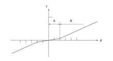
以上のように、各支持面301a,301b,302a,302b及び各収容面401a,401b,402a,402bを径方向外方に開くように傾斜させることによって、各支持部301,302及び各収容部401,402に配置されたコイルスプリング51による捩り特性は、図5に示すようになる。すなわち、コイルスプリング51が片当たり状態で圧縮される捩り角度領域Aでは低剛性であり、コイルスプリング51が両当たり状態で圧縮される捩り角度領域Bでは高剛性となる。
As described above, by inclining the support surfaces 301a, 301b, 302a, 302b and the
なお、この図5では、各支持部301,302と各収容部401,402とを回転方向にオフセットさせていない場合の捩り特性を示している。
Note that Figure 5 shows the torsional characteristics when the
<ヒス発生機構60>
ヒス発生機構60は、図1に示すように、第1ブッシュ61と、第2ブッシュ62と、コーンスプリング63と、を有している。第1ブッシュ61は、第1プレート31とフランジ42との軸方向間に配置されている。第1ブッシュ61の第1プレート31との摩擦面には、摩擦部材が固定されている。第2ブッシュ62は、第2プレート32とフランジ42との軸方向間に配置されている。第2ブッシュ62のフランジ42との摩擦面には、摩擦部材が固定されている。また、第2ブッシュ62の第2プレート32側の面には、軸方向に突出する複数の係合突起62aが形成され、この係合突起62aが第2プレート32の係合孔32bに係合している。コーンスプリング63は、第2ブッシュ62と第2プレート32との軸方向間に、圧縮された状態で配置されている。
<
As shown in FIG. 1, the
以上の構成により、第1ブッシュ61は第1プレート31に押圧され、第2ブッシュ62はフランジ42に押圧されている。したがって、入力側プレート30とハブフランジ40との間に相対回転が生じたときには、これらの間でヒステリシストルクが発生する。
With the above configuration, the
[動作]
なお、以下の動作説明及び捩り特性を示す図では、ヒステリシストルクについては省略している。また、捩り特性の説明は、中立状態から正側の捩り特性についてのみ説明する。
[motion]
In the following operation explanation and in the diagrams showing the torsional characteristics, hysteresis torque is omitted, and only the torsional characteristics from the neutral state to the positive side will be explained.
前述のように、この実施形態では、各支持部301,302の支持面、及び各収容部401,402の収容面は、径方向外方に開いて形成されている。したがって、各窓セットw1,w2では、コイルスプリング51の圧縮作動時に、片当たり状態から両当たり状態に移行する。以下では、第1窓セットw1及び第2窓セットw2において、片当たり状態による捩り剛性をk1、両当たり状態による捩り剛性をk2とする。また、オフセットが2°の場合を例にとって説明する。
As described above, in this embodiment, the support surfaces of the
<中立状態>
入力側プレート30とハブフランジ40とが相対回転していない中立状態では、図3Aに示すように、第1窓セットw1のコイルスプリング51は、R1支持面301aとR2収容面401bとの間に配置されている。このR1支持面301aとR2収容面401bとの間の間隔G0は、各支持部301,302及び各収容部401,402の幅L(コイルスプリングの自由長Sfに等しい)より狭い。したがって、第1窓セットw1では、コイルスプリング51は圧縮された状態で配置されている。このため、図6の破線で示すように、第1窓セットw1では、圧縮されたコイルスプリング51による捩りトルク-tが発生している。
<Neutral state>
In a neutral state where the
また、同様に中立状態では、第2窓セットw2のコイルスプリング51は、R1収容面402aとR2支持面302bとの間に配置されている。このR1収容面402aとR2支持面302bとの間の間隔はG0であり、各支持部301,302及び各収容部401,402の幅L(コイルスプリングの自由長Sfに等しい)より狭い。したがって、第2窓セットw2では、コイルスプリング51は圧縮された状態で配置されている。このため、図6の二点鎖線で示すように、第2窓セットw2では、圧縮されたコイルスプリング51による捩りトルク+tが発生している。
Similarly, in the neutral state, the
<第1窓セットw1の作動>
オフセットが2°の場合、第1窓セットw1では、図6の破線で示すように、捩り角度0~θ1~θ2(圧縮→自由長→圧縮)の領域においては、コイルスプリング51は、片当たり状態(剛性k1)で作動し、角度θ2を超えると、両当たり状態(剛性k2)で圧縮される。以下、第1窓セットw1の作動を、より詳細に説明する。
<Operation of first window set w1>
In the case where the offset is 2°, in the first window set w1, in the region of
ダンパユニット20にトルク変動が入力され、入力側プレート30に対してハブフランジ40が中立状態からR2側に角度θ1だけ捩れた状態を図3Bに示している。ここでは、第1窓セットw1において、コイルスプリング51のR1側の端面が当接しているR1支持面301aと、コイルスプリング51のR2側の端面が当接しているR2収容面401bと、の間の間隔G1は間隔G0よりも広くなる。この間隔G1はコイルスプリングの自由長Sfと同じである。すなわち、入力側プレート30とハブフランジ40の捩り角度が+θ1の場合、第1窓セットw1では、コイルスプリング51は自由長Sfとなって、図6に示すように、コイルスプリング51による捩りトルクは「0」となる。
Figure 3B shows a state in which torque fluctuation is input to the
以上のように、第1窓セットw1では、捩り角度0~θ1の領域では、コイルスプリング51は圧縮状態から自由長に移行し、かつ片当たり状態で作動する。したがって、捩り剛性はk1となる。
As described above, in the first window set w1, in the region of
次に、入力側プレート30に対してハブフランジ40が角度θ1を超えて捩れると、図3Cに示すように(図3Cでは捩り角度がθ2(>θ1)の場合を示している)、第1窓セットw1のコイルスプリング51のR1側の端面はR1収容面401aに当接し、R2側の端面はR2支持面301bに当接する。そして、この捩り角度θ2では、コイルスプリング51は両当たり状態になる。ここでは、R1収容面401aとR2支持面301bとの間の間隔G2は、コイルスプリング51の自由長Sfよりも狭い。すなわち、入力側プレート30とハブフランジ40の捩り角度がθ1を超えると、コイルスプリング51は自由長Sfから圧縮され、図6の破線で示すように、捩りトルクは次第に大きくなる。
Next, when the
以上のように、第1窓セットw1では、捩り角度θ1を超えた領域では、コイルスプリング51は自由長から圧縮され、捩り角度がθ2になると両当たり状態で圧縮される。したがって、捩り剛性はk2となる。
As described above, in the first window set w1, in the region exceeding the torsion angle θ1, the
<第2窓セットw2>
オフセットが2°の場合、第2窓セットw2では、図6の二点鎖線で示すように、捩り角度-θ2~-θ1~0(圧縮→自由長→圧縮)の領域においては、コイルスプリング51は、片当たり状態(剛性k1)で作動し、捩り角度0を超えると(圧縮→圧縮)、両当たり状態(剛性k2)で圧縮される。以下、第2窓セットw2の作動を、より詳細に説明する。
<Second window set w2>
When the offset is 2°, in the second window set w2, as shown by the two-dot chain line in Fig. 6, in the region of torsion angles -θ2 to -θ1 to 0 ( compression → free length → compression), the
第2窓セットw2では、入力側プレート30に対してハブフランジ40が中立状態からR2側に捩れる場合は、コイルスプリング51は、常にR1収容面402aとR2支持面302bとの間で圧縮される。すなわち、第2窓セットw2では、図6の二点鎖線で示すように、捩り角度が大きくなるにしたがって捩りトルクも大きくなる。
In the second window set w2, when the
ここでは、コイルスプリング51は圧縮状態からさらに圧縮が進み、かつ両当たり状態で圧縮され、捩り剛性はk2となる。
Here, the
<合成された特性>
以上から明らかなように、第1窓セットw1と第2窓セットw2とを合成した捩り特性は、図6の実線で示す特性となる。すなわち、各捩り角度領域における剛性は、
捩り角度0~θ2:k1+k2
θ2~ :2k2
となる。
<Synthetic properties>
As is clear from the above, the torsional characteristic obtained by combining the first window set w1 and the second window set w2 is the characteristic shown by the solid line in Figure 6. That is, the rigidity in each torsion angle region is as follows:
θ2 ~ : 2k2
It becomes.
以上のように、各支持部301,302と、対応する各収容部401,402と、をオフセットして配置し、かつ各支持面301a,301b,302a,302b及び各収容面401a,401b,402a,402bを径方向外方に開くように形成することによって、容易に2段の捩り特性を得ることができる。
As described above, by offsetting the
ここで、ダンパユニット全体の捩り特性では、中立状態では見かけ上の捩りトルクは「0」である。しかし、入力側及び出力側の部材には、正側及び負側の捩りトルクが作用している。したがって、トルク変動が+t~-tの範囲である場合は、入力側プレート30とハブフランジ40との捩り角度は-θ1~+θ1の範囲内に収まり、第1窓セットw1のコイルスプリング51の各端面は、それぞれR1収容面401a及びR2支持面301bに接触しない。また、第2窓セットw2のコイルスプリング51の各端面は、それぞれR2収容面402b及びR1支持面302aに接触しない。このため、トルク変動が+t~-tの範囲では、トルク変動による各部材間の衝突音を抑えることができる。
Here, in the torsional characteristics of the entire damper unit, the apparent torsional torque is "0" in the neutral state. However, positive and negative torsional torques act on the input and output members. Therefore, when the torque fluctuation is in the range of +t to -t, the torsional angle between the
また、捩り角度が±θ1のときに、第1窓セットw1又は第2窓セットw2のコイルスプリング51が自由長になるが、すべてのコイルスプリング51が自由長でセットされている構成に比較して部材間の衝突音を抑えることができる。
In addition, when the torsion angle is ±θ1, the coil springs 51 of the first window set w1 or the second window set w2 are at their free length, but the collision noise between components can be reduced compared to a configuration in which all
なお、捩り角度がさらに大きくなると、各窓セットw1,w2における樹脂部材52が圧縮され、さらに捩り特性はk2より大きい高剛性になる。そしてさらに捩り角度が進むと、フランジ42のストッパ用突起42bが第1プレート31のストッパ部31aに当接し、入力側プレート30とハブフランジ40との相対回転が禁止される。
When the torsion angle becomes larger, the
-第2実施形態-
図7に、各支持部301,302と、対応する各収容部401,402と、のオフセットを1°(第1実施形態のオフセット量よりも小さい例)にした場合の捩り特性を示している。
-Second embodiment-
FIG. 7 shows the torsional characteristics when the offset between each of the
ここでは、オフセット量が第1実施形態よりも小さいので、第1窓セットw1の特性は、第1実施形態に比較して負側にずれている。すなわち、図7の破線で示すように、捩り角度-θ3~θ4(圧縮→自由長→圧縮)の領域においては、コイルスプリング51は、片当たり状態(剛性k1)で作動し、角度θ4を超えると(圧縮→圧縮)、両当たり状態(剛性k2)で圧縮される。
Here, since the offset amount is smaller than in the first embodiment, the characteristic of the first window set w1 is shifted to the negative side compared to the first embodiment. That is, as shown by the dashed line in Fig. 7, in the region of torsion angles -θ3 to θ4 (compression → free length → compression ), the
また、第2窓セットw2の特性は、第1窓セットw1とは逆に、第1実施形態に比較して正側にずれている。すなわち、図7の二点鎖線で示すように、捩り角度-θ4~θ3(圧縮→自由長→圧縮)の領域においては、コイルスプリング51は、片当たり状態(剛性k1)で圧縮され、角度θ3を超えると(圧縮→圧縮)、両当たり状態(剛性k2)で圧縮される。
In addition, the characteristic of the second window set w2 is the opposite of that of the first window set w1 and is shifted to the positive side compared to the first embodiment. That is, as shown by the two-dot chain line in Fig. 7, in the region of torsion angles -θ4 to θ3 ( compression → free length → compression), the
以上から明らかなように、各コイルスプリング51の作動は、自由長から圧縮に移行するタイミングが異なるだけで、基本的に第1実施形態と同様である。
As is clear from the above, the operation of each
この第2実施形態の合成された特性は、図7の実線で示す特性となる。すなわち、各捩り角度領域における剛性は、
捩り角度0~θ3 :2k1
θ3~θ4:k1+k2
θ4~ :2k2
となる。したがって、この第2実施形態では、容易に3段の捩り特性を得ることができる。
The combined characteristic of the second embodiment is shown by the solid line in Fig. 7. That is, the stiffness in each torsion angle region is as follows:
θ3 to θ4: k1 + k2
θ4~: 2k2
Therefore, in the second embodiment, a three-stage torsional characteristic can be easily obtained.
-第3実施形態-
図8に、各支持部301,302と、対応する各収容部401,402と、のオフセットを3°(第1実施形態のオフセット量よりも大きい例)にした場合の捩り特性を示している。
--Third embodiment--
FIG. 8 shows the torsional characteristics when the offset between each of the
ここでは、オフセット量が第1実施形態よりも大きいので、第1窓セットw1の特性は、第1実施形態に比較して正側にずれている。すなわち、図8の破線で示すように、捩り角度0~θ5(圧縮)の領域においては、コイルスプリング51は、両当たり状態(剛性k2)で圧縮され、捩り角度θ5~θ6(圧縮→自由長→圧縮)の領域においては、片当たり状態(剛性k1)で作動し、角度θ6を超えると、両当たり状態(剛性k2)で圧縮される。
Here, since the offset amount is larger than in the first embodiment, the characteristic of the first window set w1 is shifted to the positive side compared to the first embodiment. That is, as shown by the dashed line in Fig. 8 , in the region of
また、第2窓セットw2の特性は、第1窓セットw1とは逆に、第1実施形態に比較して負側にずれている。すなわち、図8の二点鎖線で示すように、捩り角度-θ6~-θ5(圧縮→自由長→圧縮)の領域においては、コイルスプリング51は、片当たり状態(剛性k1)で作動し、角度-θ5を超えると(圧縮→圧縮)、両当たり状態(剛性k2)で圧縮される。
In addition, the characteristic of the second window set w2 is the opposite of that of the first window set w1 and is shifted to the negative side compared to the first embodiment. That is, as shown by the two-dot chain line in Fig. 8, in the region of torsion angles -θ6 to -θ5 ( compression → free length → compression), the
以上から明らかなように、各コイルスプリング51が圧縮される動作は、自由長から圧縮に移行するタイミングが異なるだけで、基本的には第1実施形態と同様である。
As is clear from the above, the compression operation of each
この第3実施形態の合成された特性は、図8の実線で示す特性となる。すなわち、各捩り角度領域における剛性は、
捩り角度0~θ5 :2k2
θ5~θ6:k1+k2
θ6~ :2k2
となる。したがって、この第3実施形態でも、第2実施形態と同様に、容易に3段の捩り特性を得ることができる。
The combined characteristic of the third embodiment is shown by the solid line in FIG. 8. That is, the stiffness in each torsion angle region is as follows:
θ5 to θ6: k1 + k2
θ6~: 2k2
Therefore, in the third embodiment as well, similarly to the second embodiment, a three-stage torsional characteristic can be easily obtained.
[他の実施形態]
本発明は以上のような実施形態に限定されるものではなく、本発明の範囲を逸脱することなく種々の変形又は修正が可能である。
[Other embodiments]
The present invention is not limited to the above-described embodiments, and various modifications and alterations are possible without departing from the scope of the present invention.
(a)各支持部301,302及び各収容部401,402の幅と、コイルスプリング51の自由長との関係は、前記実施形態に限定されない。
(a) The relationship between the width of each
(b)前記実施形態では、すべてのコイルスプリングの剛性を同じにしたが、異なる剛性のコイルスプリングを用いてもよい。 (b) In the above embodiment, all coil springs have the same stiffness, but coil springs of different stiffness may be used.
(c)収容部、支持部、及びコイルスプリングの個数は一例であって、前記実施形態に限定されない。 (c) The number of housings, support parts, and coil springs is an example and is not limited to the above embodiment.
(d)前記各実施形態では、各支持面及び各収容面の両方を径方向外方に開くように傾斜して形成したが、いずれか一方の面のみを傾斜してもよい。 (d) In each of the above embodiments, both the support surface and the storage surface are inclined so as to open radially outward, but only one of the surfaces may be inclined.
1 ダンパ装置
30 入力側プレート(第1回転体)
301 第1支持部
302 第2支持部
301a,302a R1支持面
301b,302b R2支持面
40 ハブフランジ(第2回転体)
401 第1収容部
402 第2収容部
401a,402a R1収容面
401b,402b R2収容面
50 弾性連結部
51 コイルスプリング(第1弾性部材、第2弾性部材)
1
301: First support portion 302:
401: First accommodating portion 402:
Claims (11)
前記回転軸の回りに前記第1回転体と相対回転可能に配置された第2回転体と、
前記第1回転体と前記第2回転体との間の相対回転による捩れがない中立状態において予め圧縮されて配置された第1弾性部材及び第2弾性部材を有し、前記第1回転体と前記第2回転体とを回転方向に弾性的に連結する弾性連結部と、
を備え、
前記第1弾性部材は、前記第1回転体が前記第2回転体に対して前記中立状態から第1回転方向に捩れる際に、圧縮状態から自由状態を経てさらに圧縮され、
前記第2弾性部材は、前記第1回転体が前記第2回転体に対して前記中立状態から第2回転方向に捩れる際に、圧縮状態から自由状態を経てさらに圧縮され、
前記第1弾性部材及び前記第2弾性部材は、圧縮作動時において円周方向の端面が片当たり状態から両当たり状態に移行する、
ダンパ装置。
A first rotor that rotates around a rotation axis;
A second rotating body arranged to be rotatable relative to the first rotating body around the rotation axis;
an elastic coupling portion that includes a first elastic member and a second elastic member that are pre-compressed and arranged in a neutral state in which there is no twisting due to relative rotation between the first rotating body and the second rotating body, and that elastically couples the first rotating body and the second rotating body in a rotational direction;
Equipped with
the first elastic member is further compressed from a compressed state through a free state when the first rotating body is twisted from the neutral state in a first rotational direction relative to the second rotating body,
the second elastic member is further compressed from a compressed state through a free state when the first rotating body is twisted from the neutral state in a second rotational direction relative to the second rotating body,
During a compression operation, the first elastic member and the second elastic member transition from a one-sided contact state to a two-sided contact state at their circumferential end surfaces.
Damper device.
前記第2弾性部材は、前記第1回転体が前記第2回転体に対して前記中立状態から前記第1回転方向に捩れる際に、圧縮状態からさらに圧縮される、
請求項1に記載のダンパ装置。
the first elastic member is further compressed from a compressed state when the first rotating body is twisted from the neutral state to the second rotating body in the second rotational direction,
the second elastic member is further compressed from the compressed state when the first rotating body is twisted from the neutral state in the first rotational direction relative to the second rotating body.
The damper device according to claim 1 .
The damper device according to claim 1 , wherein the first elastic member and the second elastic member have the same rigidity.
前記第2回転体は、前記第1支持部に対して軸方向視で一部が重なるようにかつ前記第1回転方向側にオフセットして配置された第1収容部と、前記第2支持部に対して軸方向視で一部が重なるようにかつ前記第2回転方向側にオフセットして配置された第2収容部と、を有し、
前記第1弾性部材は、前記第1支持部及び前記第1収容部に配置され、
前記第2弾性部材は、前記第2支持部及び前記第2収容部に配置され、前記第1弾性部材と並列で作動する、
請求項1から3のいずれかに記載のダンパ装置。
The first rotating body has a first support portion and a second support portion ,
the second rotating body has a first housing portion arranged to overlap with the first support portion in an axial direction and offset toward the first rotation direction, and a second housing portion arranged to overlap with the second support portion in an axial direction and offset toward the second rotation direction,
the first elastic member is disposed in the first support portion and the first housing portion,
The second elastic member is disposed in the second support portion and the second housing portion and operates in parallel with the first elastic member.
The damper device according to any one of claims 1 to 3.
前記第1収容部及び前記第2収容部は、前記第1回転方向側の端部に第1収容面を、前記第2回転方向側の端部に第2収容面を有しており、
前記第1弾性部材は、前記第1支持面と前記第2収容面との間に圧縮して配置され、
前記第2弾性部材は、前記第1収容面と前記第2支持面との間に圧縮して配置され、
前記第1支持面及び前記第1収容面の少なくともいずれか一方と、前記第2支持面及び前記第2収容面の少なくとも一方とは、径方向外方に開くように傾斜している、
請求項4に記載のダンパ装置。
each of the first support portion and the second support portion has a first support surface at an end portion on the first rotation direction side and a second support surface at an end portion on the second rotation direction side;
the first housing portion and the second housing portion have a first housing surface at an end portion on the first rotation direction side and a second housing surface at an end portion on the second rotation direction side,
The first elastic member is disposed in a compressed state between the first support surface and the second housing surface,
the second elastic member is disposed in a compressed state between the first housing surface and the second support surface,
At least one of the first support surface and the first storage surface, and at least one of the second support surface and the second storage surface are inclined so as to open radially outward.
The damper device according to claim 4.
前記第3弾性部材は、前記第1回転体が前記第2回転体に対して前記中立状態から第1回転方向に捩れる際に、圧縮状態から自由状態を経てさらに圧縮され、
前記第4弾性部材は、前記第1回転体が前記第2回転体に対して前記中立状態から第2回転方向に捩れる際に、圧縮状態から自由状態を経てさらに圧縮され、
前記第3弾性部材及び前記第4弾性部材は、圧縮作動時において円周方向の端面が片当たり状態から両当たり状態に移行する、
請求項4に記載のダンパ装置。
The elastic connecting portion further includes a third elastic member and a fourth elastic member that are pre-compressed and disposed in the neutral state,
the third elastic member is further compressed from a compressed state through a free state when the first rotating body is twisted from the neutral state to the second rotating body in a first rotational direction,
the fourth elastic member is further compressed from a compressed state through a free state when the first rotating body is twisted from the neutral state in a second rotational direction relative to the second rotating body,
The third elastic member and the fourth elastic member transition from a one-side contact state to a two-side contact state at their circumferential end surfaces during a compression operation.
The damper device according to claim 4 .
前記第2回転体は、前記回転軸を挟んで前記第1収容部と対向して配置された第3収容部と、前記回転軸を挟んで前記第2収容部と対向して配置された第4収容部と、をさらに有し、
前記第3収容部は、前記第3支持部に対して軸方向視で一部が重なるようにかつ前記第1回転方向側にオフセットして配置され、
前記第4収容部は、前記第4支持部に対して軸方向視で一部が重なるようにかつ前記第2回転方向側にオフセットして配置されており、
前記第3弾性部材は、前記第3支持部及び前記第3収容部に配置され、
前記第4弾性部材は、前記第4支持部及び前記第4収容部に配置され、前記第3弾性部材と並列で作動する、
請求項6に記載のダンパ装置。
the first rotating body further includes a third support portion disposed opposite the first support portion across the rotation shaft, and a fourth support portion disposed opposite the second support portion across the rotation shaft,
The second rotating body further includes a third housing portion disposed opposite the first housing portion across the rotation shaft, and a fourth housing portion disposed opposite the second housing portion across the rotation shaft,
the third housing portion is disposed so as to overlap with the third support portion in an axial view and to be offset toward the first rotation direction,
the fourth housing portion is disposed so as to overlap a portion of the fourth support portion in an axial direction and to be offset toward the second rotation direction,
the third elastic member is disposed in the third support portion and the third accommodation portion,
the fourth elastic member is disposed in the fourth support portion and the fourth housing portion and operates in parallel with the third elastic member;
The damper device according to claim 6.
前記第3収容部及び前記第4収容部は、前記第1回転方向側の端部に第3収容面を、前記第2回転方向側の端部に第4収容面を有しており、
前記第3弾性部材は、前記第3支持面と前記第4収容面との間に圧縮して配置され、
前記第4弾性部材は、前記第3収容面と前記第4支持面との間に圧縮して配置され、
前記第3支持面及び前記第3収容面の少なくともいずれか一方と、前記第4支持面及び前記第4収容面の少なくとも一方とは、径方向外方に開くように傾斜している、
請求項7に記載のダンパ装置。
each of the third support portion and the fourth support portion has a third support surface at an end portion on the first rotation direction side and a fourth support surface at an end portion on the second rotation direction side,
the third housing portion and the fourth housing portion have a third housing surface at an end portion on the first rotation direction side and a fourth housing surface at an end portion on the second rotation direction side,
the third elastic member is disposed in a compressed state between the third support surface and the fourth housing surface,
the fourth elastic member is disposed in a compressed state between the third housing surface and the fourth support surface,
At least one of the third support surface and the third accommodating surface, and at least one of the fourth support surface and the fourth accommodating surface are inclined so as to open radially outward.
The damper device according to claim 7.
第1捩り角度領域では、前記第1弾性部材及び前記第2弾性部材は片当たり状態であり、
前記第1捩り角度領域より大きい第2捩り角度領域では、前記第1弾性部材は片当たり状態であり、かつ前記第2弾性部材は両当たり状態であり、
前記第2捩り角度領域を超えた第3捩り角度領域では、前記第1弾性部材及び前記第2弾性部材は両当たり状態である、
請求項4に記載のダンパ装置。
the first housing portion is disposed at a predetermined angle offset toward a first rotation direction side with respect to the first support portion, and the second housing portion is disposed at the predetermined angle offset toward a second rotation direction side with respect to the second support portion,
In a first torsion angle region, the first elastic member and the second elastic member are in a one-sided contact state,
In a second torsion angle region larger than the first torsion angle region, the first elastic member is in a one-sided contact state, and the second elastic member is in a two-sided contact state,
In a third torsion angle region beyond the second torsion angle region, the first elastic member and the second elastic member are in a state of contact with each other.
The damper device according to claim 4.
第1捩り角度領域では、前記第1弾性部材は片当たり状態であり、かつ前記第2弾性部材は両当たり状態であり、
前記第1捩り角度領域を超えた第2捩り角度領域では、前記第1弾性部材は及び前記第2弾性部材は両当たり状態である、
請求項4に記載のダンパ装置。
the first housing portion is disposed at a predetermined angle offset toward a first rotation direction side with respect to the first support portion, and the second housing portion is disposed at the predetermined angle offset toward a second rotation direction side with respect to the second support portion,
In a first torsion angle region, the first elastic member is in a one-sided contact state, and the second elastic member is in a two-sided contact state,
In a second torsion angle region exceeding the first torsion angle region, the first elastic member and the second elastic member are in a state of contact with each other.
The damper device according to claim 4.
第1捩り角度領域では、前記第1弾性部材及び前記第2弾性部材は両当たり状態であり、
前記第1捩り角度領域より大きい第2捩り角度領域では、前記第1弾性部材は片当たり状態であり、かつ前記第2弾性部材は両当たり状態であり、
前記第2捩り角度領域を超えた第3捩り角度領域では、前記第1弾性部材及び前記第2弾性部材は両当たり状態である、
請求項4に記載のダンパ装置。 the first housing portion is disposed at a predetermined angle offset toward a first rotation direction side with respect to the first support portion, and the second housing portion is disposed at the predetermined angle offset toward a second rotation direction side with respect to the second support portion,
In a first torsion angle region, the first elastic member and the second elastic member are in a state of contact with each other,
In a second torsion angle region larger than the first torsion angle region, the first elastic member is in a one-sided contact state, and the second elastic member is in a two-sided contact state,
In a third torsion angle region beyond the second torsion angle region, the first elastic member and the second elastic member are in a state of contact with each other.
The damper device according to claim 4.
Priority Applications (4)
| Application Number | Priority Date | Filing Date | Title |
|---|---|---|---|
| JP2020134864A JP7461827B2 (en) | 2020-08-07 | 2020-08-07 | Damper Device |
| US17/369,174 US11841062B2 (en) | 2020-08-07 | 2021-07-07 | Damper device |
| CN202110770840.6A CN114060462A (en) | 2020-08-07 | 2021-07-07 | Vibration damping device |
| DE102021118655.2A DE102021118655A1 (en) | 2020-08-07 | 2021-07-20 | damping device |
Applications Claiming Priority (1)
| Application Number | Priority Date | Filing Date | Title |
|---|---|---|---|
| JP2020134864A JP7461827B2 (en) | 2020-08-07 | 2020-08-07 | Damper Device |
Publications (3)
| Publication Number | Publication Date |
|---|---|
| JP2022030693A JP2022030693A (en) | 2022-02-18 |
| JP2022030693A5 JP2022030693A5 (en) | 2023-07-24 |
| JP7461827B2 true JP7461827B2 (en) | 2024-04-04 |
Family
ID=79686143
Family Applications (1)
| Application Number | Title | Priority Date | Filing Date |
|---|---|---|---|
| JP2020134864A Active JP7461827B2 (en) | 2020-08-07 | 2020-08-07 | Damper Device |
Country Status (4)
| Country | Link |
|---|---|
| US (1) | US11841062B2 (en) |
| JP (1) | JP7461827B2 (en) |
| CN (1) | CN114060462A (en) |
| DE (1) | DE102021118655A1 (en) |
Citations (4)
| Publication number | Priority date | Publication date | Assignee | Title |
|---|---|---|---|---|
| JP2011236941A (en) | 2010-05-07 | 2011-11-24 | Exedy Corp | Damper mechanism |
| JP2016133123A (en) | 2015-01-15 | 2016-07-25 | アイシン精機株式会社 | Damper device |
| JP2017082981A (en) | 2015-10-30 | 2017-05-18 | 株式会社エクセディ | Damper device |
| JP2020165475A (en) | 2019-03-29 | 2020-10-08 | アイシン・エィ・ダブリュ株式会社 | Manufacturing method of dynamic damper |
Family Cites Families (9)
| Publication number | Priority date | Publication date | Assignee | Title |
|---|---|---|---|---|
| JP3848508B2 (en) * | 1999-07-19 | 2006-11-22 | 株式会社エクセディ | Damper mechanism |
| JP2001304341A (en) | 2000-04-18 | 2001-10-31 | Exedy Corp | Seat member, elastic member assembly and damper mechanism |
| JP4110020B2 (en) * | 2003-03-19 | 2008-07-02 | 株式会社エクセディ | Damper mechanism and damper disk assembly |
| JP2005106143A (en) | 2003-09-30 | 2005-04-21 | Exedy Corp | Spring assembly |
| EP1812728B1 (en) * | 2004-11-13 | 2014-09-10 | Schaeffler Technologies GmbH & Co. KG | Torque transmission device |
| JP4755000B2 (en) * | 2006-03-14 | 2011-08-24 | 株式会社エクセディ | Damper mechanism |
| WO2015129885A1 (en) * | 2014-02-28 | 2015-09-03 | アイシン・エィ・ダブリュ株式会社 | Damper apparatus |
| DE102015201962A1 (en) * | 2014-03-12 | 2015-09-17 | Schaeffler Technologies AG & Co. KG | torsional vibration dampers |
| FR3071571B1 (en) * | 2017-09-22 | 2020-01-03 | Valeo Embrayages | TORSION DAMPING DEVICE WITH MAIN DAMPER AND ADDITIONAL DAMPER |
-
2020
- 2020-08-07 JP JP2020134864A patent/JP7461827B2/en active Active
-
2021
- 2021-07-07 US US17/369,174 patent/US11841062B2/en active Active
- 2021-07-07 CN CN202110770840.6A patent/CN114060462A/en active Pending
- 2021-07-20 DE DE102021118655.2A patent/DE102021118655A1/en active Pending
Patent Citations (4)
| Publication number | Priority date | Publication date | Assignee | Title |
|---|---|---|---|---|
| JP2011236941A (en) | 2010-05-07 | 2011-11-24 | Exedy Corp | Damper mechanism |
| JP2016133123A (en) | 2015-01-15 | 2016-07-25 | アイシン精機株式会社 | Damper device |
| JP2017082981A (en) | 2015-10-30 | 2017-05-18 | 株式会社エクセディ | Damper device |
| JP2020165475A (en) | 2019-03-29 | 2020-10-08 | アイシン・エィ・ダブリュ株式会社 | Manufacturing method of dynamic damper |
Also Published As
| Publication number | Publication date |
|---|---|
| US20220042550A1 (en) | 2022-02-10 |
| DE102021118655A1 (en) | 2022-02-10 |
| CN114060462A (en) | 2022-02-18 |
| JP2022030693A (en) | 2022-02-18 |
| US11841062B2 (en) | 2023-12-12 |
Similar Documents
| Publication | Publication Date | Title |
|---|---|---|
| US20160208862A1 (en) | Damper Disk Assembly | |
| JP2008133867A (en) | Damper mechanism | |
| WO2014185148A1 (en) | Lock-up device for torque converter | |
| JP7461827B2 (en) | Damper Device | |
| WO2016129183A1 (en) | Damper disk assembly | |
| US11841061B2 (en) | Damper device | |
| JP7473420B2 (en) | Damper Device | |
| JP7473419B2 (en) | Damper Device | |
| JP4395492B2 (en) | Damper mechanism | |
| US20220056982A1 (en) | Damper device | |
| US20220056981A1 (en) | Damper device | |
| JP2000274487A (en) | Damper mechanism and damper disc assembly | |
| JP3675644B2 (en) | Damper mechanism | |
| WO2016129520A1 (en) | Damper disk assembly | |
| US11965576B2 (en) | Damper device | |
| JP7449762B2 (en) | damper device | |
| JP7422618B2 (en) | damper device | |
| JP2023112329A (en) | damper device | |
| JP2024030506A (en) | Torque limiter and power transmission device | |
| JP2021196012A (en) | Damper gear with torque limiter | |
| JP3831562B2 (en) | Damper mechanism and damper disk assembly | |
| JP3675645B2 (en) | Damper mechanism | |
| JP2023140116A (en) | damper device | |
| JP2023096692A (en) | damper device | |
| JP2023010399A (en) | damper device |
Legal Events
| Date | Code | Title | Description |
|---|---|---|---|
| A521 | Request for written amendment filed |
Free format text: JAPANESE INTERMEDIATE CODE: A523 Effective date: 20210323 |
|
| A521 | Request for written amendment filed |
Free format text: JAPANESE INTERMEDIATE CODE: A523 Effective date: 20230711 |
|
| A621 | Written request for application examination |
Free format text: JAPANESE INTERMEDIATE CODE: A621 Effective date: 20230711 |
|
| A131 | Notification of reasons for refusal |
Free format text: JAPANESE INTERMEDIATE CODE: A131 Effective date: 20240116 |
|
| A977 | Report on retrieval |
Free format text: JAPANESE INTERMEDIATE CODE: A971007 Effective date: 20240118 |
|
| A521 | Request for written amendment filed |
Free format text: JAPANESE INTERMEDIATE CODE: A523 Effective date: 20240209 |
|
| TRDD | Decision of grant or rejection written | ||
| A01 | Written decision to grant a patent or to grant a registration (utility model) |
Free format text: JAPANESE INTERMEDIATE CODE: A01 Effective date: 20240312 |
|
| A61 | First payment of annual fees (during grant procedure) |
Free format text: JAPANESE INTERMEDIATE CODE: A61 Effective date: 20240325 |
|
| R150 | Certificate of patent or registration of utility model |
Ref document number: 7461827 Country of ref document: JP Free format text: JAPANESE INTERMEDIATE CODE: R150 |