JP3675645B2 - Damper mechanism - Google Patents
Damper mechanism Download PDFInfo
- Publication number
- JP3675645B2 JP3675645B2 JP20406398A JP20406398A JP3675645B2 JP 3675645 B2 JP3675645 B2 JP 3675645B2 JP 20406398 A JP20406398 A JP 20406398A JP 20406398 A JP20406398 A JP 20406398A JP 3675645 B2 JP3675645 B2 JP 3675645B2
- Authority
- JP
- Japan
- Prior art keywords
- angle
- circumferential
- gap
- stopper
- pair
- Prior art date
- Legal status (The legal status is an assumption and is not a legal conclusion. Google has not performed a legal analysis and makes no representation as to the accuracy of the status listed.)
- Expired - Lifetime
Links
Images


Description
【0001】
【発明の属する技術分野】
本発明は、ダンパー機構、特に、動力伝達系における捩じり振動を減衰するためのダンパー機構に関する。
【0002】
【従来の技術】
車輌に用いられるクラッチディスク組立体は、フライホイールに連結・切断されるクラッチ機能と、フライホイールからの捩じり振動を吸収・減衰するためのダンパー機能とを有している。一般に車両の振動には、アイドル時異音(ガラ音)、走行時異音(加速・減速ラトル,こもり音)及びティップイン・ティップアウト(低周波振動)がある。これらの異音や振動を取り除くことがクラッチディスク組立体のダンパーとしての機能である。
【0003】
アイドル時異音とは、信号待ち等でシフトをニュートラルに入れ、クラッチペダルを放したときにトランスミッションから発生する「ガラガラ」と聞こえる音である。この異音が生じる原因は、エンジンアイドリング回転付近ではエンジントルクが低く、エンジン爆発時のトルク変動が大きいことにある。このときにトランスミッションのインプットギアとカウンターギアとが歯打ち現象を起こしている。
【0004】
ティップイン・ティップアウト(低周波振動)とは、アクセルペダルを急に踏んだり放したりしたときに生じる車体の前後の大きな振れである。駆動伝達系の剛性が低いと、タイヤに伝達されたトルクが逆にタイヤに伝達されたトルクが逆にタイヤ側からトルクに伝わり、その揺り返しとしてタイヤに過大トルクが発生し、その結果車体を過渡的に前後に大きく振らす前後振動となる。
【0005】
アイドリング時異音に対しては、クラッチディスク組立体の捩じり特性においてゼロトルク付近が問題となり、そこでの捩じり剛性は低い方が良い。一方、ティップイン・ティップアウトの前後振動に対しては、クラッチディスク組立体の捩じり特性をできるだけソリッドにすることが必要である。
以上の問題を解決するために、2種類のバネを用いることにより2段特性を実現したクラッチディスク組立体が提供されている。そこでは、捩じり特性における1段目(低捩じり角度領域)における捩じり剛性及びヒステリシストルクを低く抑えているために、アイドリング時の異音防止効果がある。また、捩じり特性における2段目(高捩じり角度領域)では捩じり剛性及びヒステリシストルクを高く設定しているため、ティップイン・ティップアウトの前後振動を十分に減衰できる。
【0006】
さらに、捩じり特性2段目においてたとえばエンジンの燃焼変動に起因する微小振動が入力されたときに、2段目の大摩擦機構を作動させないことで、低ヒステリシストルクによって微小振動を効果的に吸収するダンパー機構も知られている。
【0007】
【発明が解決しようとする課題】
捩じり特性の2段目において大摩擦機構を作動させない角度領域はたとえば2°程度の微小角度であり、入力側回転体が出力側回転体に対して回転方向駆動側(正側)に捩じれた正側2段目とその反対側(負側)に捩じれた負側2段目の両方において発生可能である。従来は大摩擦機構を作動させないための構造が正側2段目と負側2段目で同一の機構によって実現されているため、捩じり特性正側と負側とで微小振動に対して高ヒステリシストルクが発生しない円周方向角度の大きさが同一である。
【0008】
しかし、正側低ヒステリシストルク発生角度は、通常走行時のエンジントルク変動に対しては高ヒステリシストルクを発生しない程度に十分に大きい必要がある。しかし、正側低ヒステリシストルク発生角度を大きくすると、負側低ヒステリシストルク角度は負側2段目においては大きくなり過ぎることがある。具体的には、負側の低ヒステリシストルク角度が大きくなると、減速時共振周波数において両側の高ヒステリシストルクを発生させることができず、振動のピークが大きくなってしまう。
【0009】
本発明の目的は、ダンパー機構の正負両側2段目における微小捩じり振動に対する低ヒステリシストルク発生角度の大きさが同一であることに起因する問題点を解決することにある。
【0013】
【課題を解決するための手段】
請求項1に記載のダンパー機構は、出力ハブと1対の入力プレートと第1中間部材と第1弾性部材と第2中間部材とを備えている。1対の入力プレートは出力ハブの回りに相対回転可能に配置されている。第1中間部材は出力ハブの外周側で1対の入力プレートの間に配置されている。第1弾性部材は出力ハブと第1中間部材を回転方向に弾性的に連結する。第2弾性部材は第1中間部材と1対の入力プレートを回転方向に弾性的に連結し第1弾性部材より剛性が高い。第2中間部材は、出力ハブと1対の入力プレートとの間に配置され、1対の入力プレートに対して回転方向に摺動可能に摩擦係合している。第2弾性部材が回転方向に圧縮される捩り特性2段目は、1対の入力プレートが出力ハブに対して回転方向駆動側に捩れた正側と、1対の入力プレートが出力ハブに対して回転方向駆動側と反対側に捩れた負側とにそれぞれ存在している。正側2段目において第2弾性部材が作動する際に第2弾性部材が第2中間部材に作用しない第1円周方向隙間が確保されている。
負側2段目において第2弾性部材が作動する際に第2弾性部材が作用しない第2円周方向隙間が確保されている。第1円周方向隙間と第2円周方向隙間は互いに独立して設けられている。
【0014】
請求項1に記載のダンパー機構では、1対の入力プレートにトルクが入力されると、ダンパー機構を介して出力ハブにトルクが伝達される。ダンパー機構では、第1弾性部材、第1中間部材、第2弾性部材の順でトルクが伝達される。1対の入力プレートは出力ハブに対して回転方向駆動側(正側)と回転方向駆動側と反対側(負側)とに捩じれることができる。捩じり角度の小さな1段目角度領域では摩擦機構が摩擦を発生することはないためアイドリング時の異音に対して効果的である。
一方、正負両側の2段目間で1対の入力プレートと出力ハブとが繰り返し捩じれる低周波振動は、正負両側の2段目において第2弾性部材による高剛性及び摩擦機構による摩擦により十分に減衰される。さらに、2段目において所定トルク以下の捩じり振動が入力された場合には、正側2段目では第1円周方向隙間によって第2弾性部材が第2中間部材に作用せず、第2中間部材を1対の入力プレートに対して滑らせない。また、負側2段目では第2円周方向隙間によって第2弾性部材が第2中間部材に作用せず、第2中間部材を1対の入力プレートに対して滑らせない。
【0015】
ここでは、第1円周方向隙間と第2円周方向隙間とがそれぞれ独立して設けられているため、第1円周方向隙間の大きさと第2円周方向隙間の大きさを容易に異ならせることができる。この結果、第1円周方向隙間と第2円周方向隙間をそれぞれの2段目における適切な角度とすることができる。
このダンパー機構では、第2中間部材は、第1中間部材の軸方向両側に配置された1対の部材と、1対の部材同士を一体回転させるように連結する連結部材とから構成されている。第1中間部材には連結部材が貫通する孔が形成されている。第1及び第2円周方向隙間は連結部材と孔との円周方向隙間部分より形成されている。
【0016】
このダンパー機構では、第1及び第2円周方向隙間の精度を高くできる。
請求項2に記載のダンパー機構では、請求項1において、1対の入力プレートと出力ハブとの間には第1隙間角度を有する第1ストッパー機構が形成され、1対の入力プレートと第2中間部材との間には第2隙間角度を有する第2ストッパー機構が形成され、第2中間部材と第1中間部材との間には第3隙間角度を有する第3ストッパー機構が形成されている。第1隙間角度から第2隙間角度を引いた差をさらに第3隙間角度から引いた差が第1及び第2円周方向隙間の円周方向角度となる。
【0017】
請求項3に記載のダンパー機構では、請求項1又は2において、第1円周方向隙間と第2円周方向隙間は円周方向角度が異なる。
請求項4に記載のダンパー機構では、請求項3において、第2円周方向隙間の円周方向角度は第1円周方向隙間の円周方向角度より小さい。
請求項4に記載のダンパー機構では、第1円周方向隙間の角度の大きさを十分に確保しつつ、第2円周方向隙間の角度の大きさを小さくすることで減速時共振周波数における振動のピークを減らすことができる。
【0018】
請求項5に記載のダンパー機構では、請求項4において、第2円周方向隙間の円周方向角度は第1円周方向隙間の円周方向角度の約半分である。
【0019】
【発明の実施の形態】
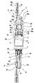
図1に本発明の一実施形態のクラッチディスク組立体1の断面図を示し、図2にその平面図を示す。クラッチディスク組立体1は、車輌のクラッチ装置に用いられる動力伝達装置であり、クラッチ機能とダンパー機能とを有している。クラッチ機能とはフライホイール(図示せず)に連結及び離反することによってトルクの伝達及び遮断をする機能である。ダンパー機能とは、バネ等によりフライホイール側から入力されるトルク変動等を吸収・減衰する機能である。
【0020】
図1においてO−Oがクラッチディスク組立体1の回転軸すなわち回転中心線である。また、図1の左側にエンジン及びフライホイール(図示せず)が配置され、図1の右側にトランスミッション(図示せず)が配置されている。さらに、図2のR1側がクラッチディスク組立体1の回転方向駆動側(正側)であり、R2側からその反対側(負側)である。
【0021】
クラッチディスク組立体1は、主に、入力回転体2(クラッチプレート21, リテーニングプレート22, クラッチディスク23)と、出力回転体3(ハブ)と、入力回転体2と出力回転体3との間に配置されたダンパー機構とから構成されている。ダンパー機構は、第1バネ7, 第2バネ8及び大摩擦機構13などを含んでいる。
【0022】
入力回転体2はフライホイール(図示せず)からのトルクが入力される部材である。入力回転体2は、主に、クラッチプレート21と、リテーニングプレート22と、クラッチディスク23とから構成されている。クラッチプレート21とリテーニングプレート22は共に板金製の円板状又は環状の部材であり、軸方向に所定の間隔を空けて配置されている。クラッチプレート21はエンジン側に配置され、リテーニングプレート22はトランスミッション側に配置されている。クラッチプレート21とリテーニングプレート22は後述する板状連結部31により互いに固定され、その結果軸方向の間隔が定めされるとともに一体回転するようになっている。
【0023】
クラッチディスク23は、図示しないフライホイールに押し付けられる部分である。クラッチディスク23は、クッショニングプレート24と、第1及び第2摩擦フェーシング25とから主に構成されている。クッショニングプレート24は、環状部24aと、環状部24aの外周側に設けられ回転方向に並ぶ複数のクッショニング部24bと、環状部24aから半径方向内側に延びる複数の連結部24cとから構成されている。連結部24cは4カ所に形成され、各々がリベット27(後述)によりクラッチプレート21に固定されている。クッショニングプレート24の各クッショニング部24bの両面には、摩擦フェーシング25がリベット26により固定されている。
【0024】
クラッチプレート21及びリテーニングプレート22の外周部には、回転方向に等間隔で4つの窓孔35がそれぞれ形成されている。各窓孔35には、内周側と外周側にそれぞれ切り起こし部35a,35bが形成されている。この切り起こし部35a, 35bは後述の第2バネ8の軸方向及び半径方向への移動を規制するためのものである。また、窓孔35には、第2バネ8の端部に当接又は近接する当接面36が円周方向両端に形成されている。
【0025】
クラッチプレート21及びリテーニングプレート22には、それぞれ中心孔37(内周縁)が形成されている。この中心孔37内には出力回転体3としてのスプラインハブが配置されている。出力回転体3は、軸方向に延びる筒状のボス52と、ボス52から半径方向に延びるフランジ54とから構成されている。ボス52の内周部には、トランスミッション側から延びる図示しないシャフトに係合するスプライン孔53が形成されている。フランジ54には回転方向に並んだ複数の外周歯55及び後述の第1バネ7を収容するための切欠き56等が形成されている。切欠き56は半径方向に対向する2カ所に形成されている。
【0026】
分離フランジ6は、出力回転体3の外周側で、かつ、クラッチプレート21とリテーニングプレート22との間に配置された円板状の部材である。分離フランジ6は、第1バネ7を介して出力回転体3と回転方向に弾性的に連結され、さらには第2バネ8を介して入力回転体2に弾性的に連結されている。図7〜9に詳細に示すように、分離フランジ6の内周縁には複数の内周歯59が形成されている。
【0027】
内周歯59は前述の外周歯55の間に配置され、回転方向に所定の隙間をあけて配置されている。外周歯55と内周歯59とは回転方向に互いに当接可能である。すなわち外周歯55と内周歯59とにより出力回転体3と分離フランジ6との捩じり角度を規制するための第1ストッパー9が形成されている。ここでいうストッパーとは、所定角度までは両部材の相対回転を許容するが、所定角度になると互いに当接しそれ以上の相対回転を禁止する構造をいう。外周歯55とその円周方向両側の内周歯59との間にはそれぞれ第1隙間角度θ1が確保されている。外周歯55から見てR2側の内周歯59との間の第1隙間角度θ1pは8°であり、外周歯55から見てR1側の内周歯59との間の第1隙間角度θ1nは2°である。このように第1隙間角度θ1pとθ1nは角度の大きさが異なり、θ1pはθ1nより大きい。
【0028】
さらに、分離フランジ6の内周縁には、フランジ54の切欠き56に対応して切欠き67が形成されている。切欠き56, 67内には、それぞれ1つずつ合計2つの第1バネ7が配置されている。第1バネ7は低剛性のコイルスプリングであり、2つの第1バネ7は並列に作用する。第1バネ7は円周方向両端においてスプリングシート7aを介して切欠き56, 67の円周方向両端に係合している。以上の構造によって、出力回転体3と分離フランジ6とが相対回転する際には第1隙間角度θ1の範囲内で第1バネ7が回転方向に圧縮される。
【0029】
分離フランジ6には回転方向に等間隔で4つの窓孔41が形成されている。窓孔41は回転方向に長く延びる形状である。図5及び図6に示すように、窓孔41の縁は、円周方向両側の当接部44と、外周側の外周部45と、内周側の内周部46とから構成されている。外周部45は連続して形成されており窓孔41の外周側を閉じている。なお、窓孔41の外周側は一部が半径方向外方に開いた形状であってもよい。分離フランジ6において各窓孔41の円周方向間には切欠き42が形成されている。切欠き42は半径方向内側から外側に向かって円周方向長さが長くなる扇形状であり、円周方向両側に縁面43が形成されている。
【0030】
各窓孔41が形成された部分の半径方向外側には、突起49が形成されている。すなわち突起49は分離フランジ6の外周縁48からさらに半径方向外側に延びる突起形状である。突起49は、回転方向に長く延びており、ストッパー面50が形成されている。突起49は、窓孔41に比べて円周方向の幅が短く、ほぼその円周方向中間位置に形成されている。すなわち、突起49のストッパー面50は、切欠き42の縁面43より窓孔41に対してさらに円周方向内側に配置されており、窓孔41の当接部44よりさらに円周方向内側に配置されている。なお、突起49は円周方向両端にストッパー面が形成されていればそれでよく、必ずしも円周方向中間部分を必要としない。すなわち、突起は両側ストッパー面を形成するために円周方向2カ所に設けられた形状であっても良い。
【0031】
前述した分離フランジ6の構造について他の表現を用いて再度説明する。分離フランジ6は内周側に環状部を有しており環状部から半径方向外方に突出する複数の突出部47を有している。各突出部47はこの実施形態では回転方向に等間隔で4つ形成されている。突出部47は回転方向に長く形成されており、その内部に前述の窓孔41が形成されている。窓孔41は突出部47においてその面積の70%以上を占めており、突出部47にわたって形成されている。
【0032】
さらに突出部47を他の表現で説明すると、突出部47は、半径方向に延びる2つの円周方向両側窓枠部91と、円周方向両側窓枠部91の半径方向外側端同士を連結する外周側窓枠部92とから構成されている。円周方向両端窓枠部91の円周方向内側は当接部44となり、円周方向外側は縁面43となっている。外周側窓枠部92の半径方向内側は外周部45となっており、半径方向外側は外周縁48となっている。外周縁48には前述の突起49が形成されている。なお、前述の切欠き42は回転方向に隣接する突出部47の円周方向両端窓枠部91間の空間である。
【0033】
第2バネ8はクラッチディスク組立体1のダンパー機構に用いられる弾性部材すなわちバネである。各第2バネ8は、同心に配置された1対のコイルスプリングから構成されている。各第2バネ8は各第1バネ7に比べて大型であり、バネ定数が大きい。第2バネ8は各窓孔41, 35内に収容されている。第2バネ8は回転方向に長く延びており、窓孔41全体にわたって配置されている。すなわち第2バネ8の円周方向角度は後述の窓孔41の円周方向角度θBとほぼ等しい。第2バネ8の円周方向両端は、窓孔41の当接部44と当接面36とに当接又は近接している。プレート21, 22のトルクは第2バネ8を介して分離フランジ6に伝達され得る。プレート21, 22と分離フランジ6とが相対回転すると、第2バネ8は両者の間で圧縮される。具体的には、第2バネ8は当接面36とその円周方向反対側の当接部44との間で回転方向に圧縮される。このとき4つの第2バネ8は並列に作用している。
【0034】
リテーニングプレート22の外周縁には、回転方向に等間隔で4カ所に板状連結部31が形成されている。板状連結部31は、クラッチプレート21とリテーニングプレート22とを互いに連結するものであり、さらに後述するようにクラッチディスク組立体1のストッパーの一部を構成している。板状連結部31は、リテーニングプレート22から一体に形成された板状部材であり、回転方向に所定の幅を有している。板状連結部31は、各窓孔41の円周方向間すなわち切欠き42に対応して配置されている。板状連結部31は、リテーニングプレート22の外周縁から軸方向に延びるストッパー部32と、ストッパー部32の端部から半径方向内側に延びる固定部33とから構成されている。ストッパー部32はリテーニングプレート22の外周縁からクラッチプレート21側に延びている。固定部33は、ストッパー部32の端部から半径方向内側に折り曲げられている。以上に述べた板状連結部31はリテーニングプレート22と一体の部分であり、厚みはリテーニングプレート22とほぼ同じである。そのため、ストッパー部32は、主面が半径方向に向いており、半径方向にはリテーニングプレート22の板厚に相当する幅のみを有している。ストッパー部32は円周方向両側にストッパー面51を有している。固定部33の半径方向位置は窓孔41の外周側部分に対応しており、円周方向位置は回転方向に隣接する窓孔41の間である。この結果、固定部33は分離フランジ6の切欠き42に対応して配置されている。切欠き42は固定部33より大きく形成されており、このため組立時にリテーニングプレート22をクラッチプレート21に対して軸方向に移動させたときには固定部33は切欠き42を通って移動可能である。固定部33はクッショニングプレート24の連結部24cに平行にかつトランスミッション側から当接している。固定部33には孔33aが形成されており、孔33a内には前述のリベット27が挿入されている。リベット27は、固定部33とクラッチプレート21とクッショニングプレート24とを一体に連結している。さらに、リテーニングプレート22において固定部33に対応する位置にはかしめ用孔34が形成されている。
【0035】
次に、板状連結部31のストッパー部32と突起49とからなる第2ストッパー10について説明する。第2ストッパー10は分離フランジ6と入力回転体2との間で隙間角度θ4までの領域で両部材の相対回転を許容し、捩り角度がθ4になると両部材の相対回転を規制するための機構である。なお、この隙間角度θ4の間で第2バネ8は分離フランジ6と入力回転体2との間で圧縮される。
【0036】
板状連結部31は、平面視において、円周方向位置は窓孔41の円周方向間、切欠き42内、突起49の円周方向間にある。また、板状連結部31のストッパー面51の半径方向位置は、分離フランジ6の外周縁48よりさらに半径方向外側にある。すなわち、ストッパー部32と突起49とは半径方向位置がほぼ同じである。このため、ストッパー部32と突起49は分離フランジ6とプレート21, 22との捩り角度が大きくなると互いに当接可能である。ストッパー部32のストッパー面51と突起49のストッパー面50とが互いに当接した状態では、ストッパー部32は分離フランジ6の突出部47すなわち窓孔41の半径方向外側に位置している。すなわち、ストッパー部32が突出部47及び窓孔41よりさらに円周方向内側に入り込むことが可能になっている。
【0037】
以上に述べた第2ストッパー10の利点について説明する。ストッパー部32は板状であるため、従来のストップピンに比べて円周方向角度を短くできる。また、ストッパー部32は従来のストップピンに比べて半径方向長さが大幅に短くなっている。すなわちストッパー部32の半径方向長さはプレート21, 22の板の厚みと同じだけである。このことは、第2ストッパー10の実質的な半径方向長さはプレート21, 22の板厚に相当する短い部分に限定されていることを意味する。
【0038】
ストッパー部32はプレート21, 22の外周縁部分すなわち最外周位置に配置されており、ストッパー部32の半径方向位置は突出部47特に窓孔41の外周縁48の半径方向位置よりさらに半径方向外側である。このようにストッパー部32が窓孔41から半径方向に異なる位置にあるため、ストッパー部32と窓孔41とが回転方向に互いに干渉しない。この結果、第2バネ8によるダンパー機構の最大捩り角度と第2バネ8の捩り角度を共に大きくできる。ストッパー部が窓孔と同じ半径方向位置にある場合には、第2バネによるダンパー機構の捩り角度と窓孔の円周方向角度とは互いに干渉し合い、ダンパー機構の広角化とバネの低剛性化を実現できない。
【0039】
特に、第2ストッパー10の半径方向長さが従来のストップピンに比べて大幅に短いため、第2ストッパー10を窓孔41の半径方向外側に設けても、プレート21, 22の外径は極端に大きくならない。また、窓孔41の半径方向長さが極端に短くなることはない。
突起49から見てR2側のストッパー部32との間の第4隙間角度θ4pは26゜であり、突起49から見てR1側ストッパー部32との間の第4隙間角度θ4nは23.5゜である。このようにθ4pはθ4nと大きさが異なり、θ4pはθ4nより大きい。以上に述べたθ4pとθ4nの関係を実現するために、突起49はストッパー部32の円周方向間に中心位置から円周方向にずれて配置されている。より具体的には、突出部47の円周方向中心位置はストッパー部32の円周方向間中心位置のR1側に位置している。
【0040】
中間プレート11は、出力回転体3の外周側において、クラッチプレート21と分離フランジ6との間、及び分離フランジ6とリテーニングプレート22との間に配置された1対のプレート部材である。中間プレート11は円板状または環状のプレート部材であり、入力回転体2と出力回転体3との間でダンパー機構の一部を構成している。中間プレート11の内周縁には複数の内周歯66が形成されている。内周歯66は分離フランジ6の内周歯59と軸方向に重なるように配置されている。図5〜7に詳細に示すように、内周歯66は内周歯59に比べて円周方向幅が広く、その円周方向両側に両端がはみでている。内周歯66は、出力回転体3の外周歯55と回転方向に所定の隙間をあけて配置されている。すなわちこの隙間の範囲内で出力回転体3と中間プレート11とは相対回転可能となっている。外周歯55と内周歯59とにより、出力回転体3と中間プレート11との相対回転角度を規制する第3ストッパー12が形成されている。より具体的には、図7に示すように、外周歯55と内周歯66との間には第2隙間角度θ2の隙間が確保されている。外周歯55から見てR2側の内周歯66との間の第2隙間角度θ2pは7.5°であり、外周歯55から見てR1側の内周歯66との間の第2隙間角度θ2nは1.5°である。このようにθ2pはθ2nと大きさが異なり、大きい。第2隙間角度θ2pは第1隙間角度θ1pより小さく、第2隙間角度θ2nは第1隙間角度θ1nより小さい。
【0041】
1対の中間プレート11のうちリテーニングプレート22側に配置された中間プレート11には、半径方向外側に延びる複数の突出部61が形成されている。各突出部61は分離フランジ6の窓孔41の間に配置されている。窓孔41の先端には、半円形状の位置合わせ切欠き61aが形成されている。この切欠き61aは、分離フランジ6に形成された位置合わせ用の切欠き98やプレート21,22に形成された位置合わせ用の孔に対応している。
【0042】
1対の中間プレート11同士は、複数のピン62により相対回転不能かつ軸方向の位置決めがされている。ピン62は、胴部と、胴部から軸方向両側に延びる頭部とから構成されている。1対の中間プレート11同士はピン62の胴部端面に軸方向から当接することによって互いに対して軸方向に接近することが制限されている。中間プレート11の頭部は中間プレート11に形成された孔内に挿入され自らと胴部との間に中間プレート11を挟んでいる。各中間プレート11と分離フランジ6との間には、それぞれスペーサ63が配置されている。スペーサ63は各中間プレート11の内周部と分離フランジ6の内周側環状部分との間にそれぞれ配置された環状のプレート部材である。スペーサ63にはピン62の胴部が挿入される孔が形成されており、ピン62と孔の係合によってスペーサ63は中間プレート11と一体回転する。スペーサ63において分離フランジ6に対向し当接する側の面には摩擦係数を減らすためのコーティングが施されている。分離フランジ6にはピン62が貫通する複数の孔69が形成されている。ピン62は孔69に対して円周方向両側に所定角度だけ相対移動可能である。すなわちピン62の胴部と孔69の円周方向両側端面との円周方向間に第3隙間角度θ3の隙間が確保されている。これにより第4ストッパー14が形成されている。ピン62から見てR2側の孔69端面との間には第3隙間角度θ3pが確保されている、ピン62から見てR1側の孔69端面との間には第3隙間角度θ3nが確保されている。第3隙間角度θ3pとθ3nは大きさが異なり、θ3pは0.90°であり、θ3nは0.70°である。
【0043】
以上に述べたピン62と孔69との相対的位置関係は、ピン62が図7に示す中立状態において孔69に対してR2側にずれていることを意味している。より具体的にはピン62の円周方向中心位置は孔69の円周方向中心位置よりR2側に位置している。この位置関係は、ピン62の位置を移動させること、又は分離フランジ6の孔69の大きさを円周方向両側で変えることで実現される。
【0044】
次に、摩擦発生機構を構成する各部材について説明する。第2摩擦ワッシャー72は、トランスミッション側の中間プレート11の内周部とリテーニングプレート22の内周部との間に配置されている。第2摩擦ワッシャー72は主に樹脂製の本体74から構成されている。本体74の摩擦面は、トランスミッション側の中間プレート11のトランスミッション側面に当接している。本体74の内周部からはトランスミッション側に係合部76が延びている。係合部76は、リテーニングプレート22に対して相対回転不能に係合されるとともに軸方向に係止されている。本体74の内周部トランスミッション側には複数の凹部77が形成されている。本体74とリテーニングプレート22との間には第2コーンスプリング73が配置されている。第2コーンスプリング73は、第2摩擦ワッシャー72の本体74とリテーニングプレート22との間で圧縮された状態で配置されている。これにより、第2摩擦ワッシャー72の摩擦面は第1中間プレート11に強く圧接されてている。第1摩擦ワッシャー79はフランジ54とリテーニングプレート22の内周部との間に配置されている。すなわち、第1摩擦ワッシャー79は第2摩擦ワッシャー72の内周側でかつボス52の外周側に配置されている。第1摩擦ワッシャー79は樹脂製である。第1摩擦ワッシャー79は、主に環状の本体81から構成されており、環状の本体81からは複数の突起82が半径方向外側に延びている。本体81はフランジ54に当接しており、複数の突起82は第2摩擦ワッシャー72の凹部77に相対回転不能に係合している。これにより、第1摩擦ワッシャー79は第2摩擦ワッシャー72を介してリテーニングプレート22と一体回転可能である。第1摩擦ワッシャー79とリテーニングプレート22の内周部との間には第1コーンスプリング80が配置されている。第1コーンスプリング80は第1摩擦ワッシャー79とリテーニングプレート22の内周部との間で軸方向に圧縮された状態で配置されている。なお、第1コーンスプリング80の付勢力は第2コーンスプリング73の付勢力より小さくなるように設計されている。また、第1摩擦ワッシャー79は第2摩擦ワッシャー72に比べて摩擦係数が低い材料から構成されている。このため、第1摩擦ワッシャー79によって発生する摩擦(ヒステリシストルク)は第2摩擦ワッシャー72で発生する摩擦より大幅に小さくなっている。
【0045】
クラッチプレート21の内周部とフランジ54及び中間プレート11の内周部との間には第3摩擦ワッシャー85と第4摩擦ワッシャー86が配置されている。第3摩擦ワッシャー85及び第4摩擦ワッシャー86は樹脂製の環状部材である。第3摩擦ワッシャー85はクラッチプレート21の内周縁に相対回転不能に係合し、その内周面はボス52の外周面に摺動可能に当接している。すなわち、クラッチプレート21は第3摩擦ワッシャー85を介してボス3に半径方向の位置決めをされている。第3摩擦ワッシャー85はフランジ54に対して軸方向エンジン側から当接している。第4摩擦ワッシャー86は第3摩擦ワッシャー85の外周側に配置されている。第4摩擦ワッシャー86は環状の本体87と、環状の本体87から軸方向エンジン側に延びる複数の係合部88を有している。本体87は軸方向エンジン側の中間プレート11に当接する摩擦面を有している。係合部88はクラッチプレート21に形成された孔内に相対回転不能に係合している。また、係合部88はクラッチプレート21の軸方向エンジン側面に当接する爪部を有している。第3摩擦ワッシャー85と第4摩擦ワッシャー86は互いに相対回転不能に係合している。なお、第3摩擦ワッシャー85と第4摩擦ワッシャー86は別体の部材であり、第4摩擦ワッシャー86は第3摩擦ワッシャー85に対して摩擦係数が高い材料から構成されている。
【0046】
以上に述べた摩擦機構において、第2摩擦ワッシャー72及び第4摩擦ワッシャー86と中間プレート11との間に比較的高いヒステリシストルクを発生させる大摩擦機構13(摩擦機構)が形成されていることになる。さらに、第1摩擦ワッシャー79及び第3摩擦ワッシャー85と、フランジ54との間に低ヒステリシストルクを発生する小摩擦機構15を形成している。
【0047】
次に第2バネ8と第2ストッパー10における各構造の角度及びその関係について詳細に説明する。なお、以下に述べる「円周方向角度」とは、ある位置から他の位置までのクラッチディスク組立体1の回転軸O−Oを中心とした円周方向(クラッチディスク組立体1の回転方向)角度のことである。以下の説明で用いる角度の絶対値は図面に記載された本願発明の一例としてのクラッチディスク組立体1のものであり、本願発明はそれらの数値に限定されない。
θAとθCとの関係
各突起49の円周方向角度θA(図6)は、回転方向に隣接する突起49の隣接する円周方向端部間(すなわち回転方向に向き合うストッパー面50間)の円周方向角度θC(図5)より小さい。θAとθCは一方が大きくなれば他方が小さくなる関係にある。ここではθAをθCに対して大幅に小さくすることでθCを従来より大きく確保している。このように各突起49間の円周方向角度θCが広くなることにより、分離フランジ6とプレート21, 22との間の第4隙間角度θ4(θ4p+θ4n)を広くすることが可能となっている。
【0048】
θCは、40゜以上あれば従来にない充分に優れた効果が得られ、50〜80゜
の範囲にある場合はさらに優れた効果が得られ、60〜80゜の範囲にある場合はさらに優れた効果が得られ65〜75゜の範囲にある場合は最も優れた効果が得られる。
【0049】
θAはθCの2分の1以下であれば充分に優れた効果が得られる。θAはθCの3分の1以下であればさらに優れた効果が得られる。
θCとθDとの関係
各板状連結部31(ストッパー部32)の円周方向角度θDは、前述の角度θCより遙かに小さくなっている。θCからθDを引いたものが、分離フランジ6とプレート21, 22との間の最大隙間角度θ4(θ4p+θ4n,ダンパー機構のストッパー角度)になっている。すなわち、このダンパー機構では最大隙間角度θ4が従来より広くなっている。図から明らかなように、θ4を広くするためには、θCを大きくし、θDを小さくすることが必要であることがわかる。この実施形態においてはθDは18゜になっている。θDは20゜以下であるのが好ましく、10〜20゜の範囲にあるのがさらに好ましい。
【0050】
θDがθCの2分の1以下であれば、θDは充分に広く確保され、3分の1であればさらにθ4は広くなり、4分の1以下であればθ4を最も広くできる。
この実施形態ではθ4は58.5゜である。θEは20゜以上であるのが好ましい。θEは30゜以上であるのが好ましい。特に40〜60゜の範囲にあれば従来にない充分な広角化が達成されており、55〜60゜の範囲にあればさらに好ましい。
【0051】
最大捩じり角度θ4が増大することにより以下の効果が得られる。広捩じり角が達成されると、ストッパートルクを低下させることなく、捩じり特性の2段目のバネ(第2バネ8)の剛性を低くできる。この実施形態では従来に比べて第2バネ8の剛性を約50%程度まで低くしている。この結果、2段目から2段目に移行するときのショック(アクセル踏み込み時、最初の突き上げ感)が減少する。
【0052】
θBとθDとの関係
分離フランジ6に形成された窓孔41は合計4つであり、各窓孔41の円周方向角度θBは50゜以上ある。θBは当接部44の半径方向中間部同士間で測定されている。図面におけるθBは59゜である。この結果、回転方向に充分に長いつまり広角化したバネを用いることができる。θBは50〜70゜の範囲にあるのが好ましく、55〜65゜の範囲にあればさらに好ましい。
【0053】
各突起49の円周方向角度θDは各窓孔41の円周方向角度θBより小さい。これはθ4のθBに対する比が十分に大きいことを意味している。すなわち広角化した窓孔41及び第2バネ8に対してダンパー機構の最大捩り角度を充分に広くすることによって、バネの機能を有効に利用し、さらに広捩り角度・低捩り剛性の特性を得られる。
【0054】
θDがθBの2分の1以下である場合は充分に優れた効果が得られ、3分の1以下である場合はさらに優れた効果が得られる。
θAとθBとの関係
突起49の円周方向角度θAは各窓孔41の円周方向角度θBより小さい。θAのθBに対する比が従来より小さいということは、θCのθBに対する比が従来より大きいことを示す。言い換えると、広角化した窓孔41に対して最大隙間角度θ4を広く確保する前提となるθCのθBに対する比が充分に大きい。各突起49の円周方向角度θAは窓孔41の円周方向角度θBの2/3以下であればよく、1/2以下であればより好ましく、1/3以下であればさらに好ましい。
【0055】
θBとθ4との関係
θ4とθBは共に従来に比べて大きくなっており、これによりダンパー機構の最大捩り角度が大きくなると共に第2バネ8の捩り角度が広くなっている。第2バネ8は大型化されることによって設計が容易になり、高性能(広捩り角・低剛性)になっている。
【0056】
θBとθ4を比較すると、両者はほとんど実質的な差がない。すなわち、θBのθ4に対する比が充分に大きくなっている。これにより窓孔41すなわち第2バネ8の円周方向角度を広くした場合においで、その広角度を充分に生かせる最大隙間角度θ4が確保されている。
窓孔41の半径方向長さ
このダンパー機構では、窓孔41の半径方向長さが分離フランジ6の半径方向長さ(外径)に比べて充分に大きくなっている。この結果、窓孔41に収容する第2バネ8の大型化が可能となっている。窓孔41の半径方向長さは分離フランジ6の外径の35%以上である。この割合が35〜55%の範囲にある場合は充分に優れた効果を得ることができ、40〜50%の範囲にある場合はさらに優れた効果を得ることができる。
【0057】
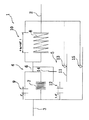
次に、図10を用いてクラッチディスク組立体1の構成についてさらに説明する。図10はクラッチディスク組立体1のダンパー機構の機械回路図である。この機械回路図は、ダンパー機構における各部材の回転方向の関係を模式的に描いたものである。したがって一体回転する部材は同一の部材として取り扱っている。
【0058】
図10から明らかなように、入力回転体2と出力回転体3との間にはダンパー機構を構成するための複数の部材が配置されている。分離フランジ6は入力回転体2と出力回転体3との回転方向間に配置されている。分離フランジ6は出力回転体3に第1バネ7を介して回転方向に弾性的に連結されている。また、分離フランジ6と出力回転体3との間には第1ストッパー9が形成されている。第1ストッパー9における第1隙間角度θ1pの間で第1バネ7は圧縮可能である。分離フランジ6は入力回転体2に対して第2バネ8を介して回転方向に弾性的に連結されている。また、分離フランジ6と入力回転体2との間には第2ストッパー10が形成されている。第2ストッパー10における第4隙間角度θ4pの間で第2バネ8は圧縮可能となっている。以上に述べたように、入力回転体2と出力回転体3と直列に配置された第1バネ7と第2バネ8とにより回転方向に弾性的に連結されている。ここでは、分離フランジ6は2種類のバネの間に配置された中間部材として機能している。また、以上に述べた構造は、並列に配置された第1バネ7及び第1ストッパー9からなる第1ダンパーと、並列に配置された第2バネ8と第2ストッパー10からなる第2ダンパーとが、直列に配置された構造として見ることもできる。また、以上に述べた構造を入力回転体2と出力回転体3とを回転方向に弾性的に連結するダンパー機構4として考えることができる。第1バネ7全体の剛性は第2バネ8全体の剛性よりはるかに小さく設定されている。そのため、第1隙間角度θ1までの捩り角度の範囲で第2バネ8はほとんど回転方向に圧縮されない。
【0059】
中間プレート11は、入力回転体2と出力回転体3との回転方向間に配置されている。中間プレート11は、出力回転体3と分離フランジ6との間で相対回転するように配置されている。中間プレート11は、出力回転体3との間に第3ストッパー12を構成し、分離フランジ6との間に第4ストッパー14を構成している。さらに、中間プレート11は、大摩擦機構13を介して入力回転体2に回転方向に摩擦係合している。以上に述べた中間プレート11は、入力回転体2, 出力回転体3及び分離フランジ6の間に配置されることで摩擦連結機構5を構成している。
【0060】
次に、図10におけるダンパー機構の各隙間角度θ1p〜θ4pの関係について説明する。ここで説明する隙間角度は、出力回転体3から入力回転体2をR2側に見た各角度である。第1ストッパー9における第1隙間角度θ1pは第1バネ7が円周方向に圧縮される角度範囲となっており、第2ストッパー10における第4隙間角度θ4pは第2バネ8が回転方向に圧縮される角度範囲となっている。第1隙間角度θ1pと第4隙間角度θ4pとの合計がクラッチディスク組立体1全体としてのダンパー機構の正側最大捩り角度である。第1隙間角度θ1pから第2隙間角度θ2pを引いた差をさらに第3隙間角度θ3pから引いたものが、捩り特性の正側2段目において微小捩り振動が入力された時に大摩擦機構13を作動させないための正側2段目隙間角度θACp(第1摩擦抑制機構、第1円周方向隙間)となっている。正側2段目隙間角度θACpの大きさ(第1角度範囲)はこの実施形態では0.4゜と従来に比べて大幅に小さくなっており、0.3〜0.5゜の範囲にあることが好ましい。
【0061】
次に、図20におけるダンパー機構の各隙間角度θ1n〜θ4nの関係について説明する。ここで説明する隙間角度は、出力回転体3から入力回転体2をR1側に見た各角度である。第1ストッパー9における第1隙間角度θ1nは第1バネ7が円周方向に圧縮される角度範囲を示しており、第2ストッパー10における第4隙間角度θ4nは第2バネ8が回転方向に圧縮される角度範囲を示している。第1隙間角度θ1nと第4隙間角度θ4nとの合計がクラッチディスク組立体1全体としてのダンパー機構の負側最大捩り角度である。第1隙間角度θ1nから第2隙間角度θ2nを引いた差をさらに第3隙間角度θ3nから引いたものが、捩り特性の負側2段目において微小捩り振動が入力された時に大摩擦機構13を作動させないための負側2段目隙間角度θACn(第2摩擦抑制機構,第2円周方向隙間)となっている。負側2段目隙間角度θACnの大きさ(第2角度範囲)はこの実施形態では0.2゜と従来に比べて大幅に小さくなっており、0.15〜0.25゜の範囲にあることが好ましい。
【0062】
正側2段目隙間角度θACpと負側2段目隙間角度θACnについてさらに詳細に説明する。θACpは、図8に示すように、ピン62のR2側部と孔69ののR2側部との間に形成されている。θACnは、図9に示すように、ピン62のR1側部と孔69のR1側部との間に形成されている。このようにθACpとθACnは独立で、別個に設けられた構造である。すなわち従来のように単一の隙間を正側2段目と負側2段目で共通に使う構造ではない。このため、θACpとθACnとを異ならせることが可能となる。したがってθACpとθACnを各々適切な大きさに設定できる。
【0063】
ここでは、θACnは、θACpに比べて小さく、具体的にはθACpの約1/2になっている。このため、θACpは通常走行時にエンジンの燃焼変動に起因する微小振動を減衰するための低ヒステリシストルク領域を十分に確保できる。また、θACnはθACpに合わせて大きくする必要がないため、減速時共振周波数において十分に両側の高ヒステリシストルクを発生させることができる。この結果、減速時共振周波数において振動のピークを減らすことができる。
【0064】
θACnを極端に小さく、ほとんどゼロ又は完全にゼロにすることもできる。その場合は減速時共振周波数の振動レベルを極端に小さくできる。
逆にθACnをθACpより大きくしてもよい場合がある。これは負側作動時においてはエンジントルク変動を減衰するためにθACnを大きくし、正側作動時には加速時共振周波数での両側で発生する高ヒステリシストルクを発生しやすくすためにθACpを小さくしたいという要望があるときに採用される。
【0065】
次にθACnとθACpを形成する具体的な構造について説明する。すでに説明したように、θACp=θ3p−(θ1p−θ2p)であり、θACn=θ3n−(θ1n−θ2n)である。θ1p−θ2p= θ1n−θ2nなので、θACpとθACnの差は、θ3pとθ3nとの差により実現されていることが分かる。さらに、θ3pとθ3nとの差は、具体的には、孔69に対してピン62がR2側に中心位置がずれていることにより生じている。ピン62と孔69との関係の調整によってθACpとθACnの差は簡単に変更できる。
【0066】
また、θACpとθACnは軸方向に伸びる連結部材としてのピン62と分離フランジ6の孔69との間に形成されるため、精度を高く保つことができる。この結果、1°未満の微小角度を実現できる。なお、孔69は一部が開いた切り欠き形状であってもよい。
また、θACpとθACnが中間プレート11と第2バネ8との間に設けられている構造にも、本発明を採用できる。
【0067】
正負両側の第2隙間角度θ2p, θ2nの合計が、捩り特性の正負2段目において微小捩り振動が入力された時に大摩擦機構13を作動させないための1段目隙間角度θACになる。この実施形態では2段目隙間角度ACの大きさは9°になる。2段目隙間角度ACは正側2段目隙間角度θACpや負側2段目隙間角度θACnより大きいことが好ましく、2倍以上あるのが好ましい。また、10倍以上、さらには20倍以上あっても良い。
【0068】
また、図10に示すように、入力回転体2と出力回転体3との間には小摩擦機構15が設けられている。小摩擦機構15は入力回転体2と出力回転体3が相対回転する際には常に滑りが生じるようになっている。この実施形態では、小摩擦機構15は主に第2摩擦ワッシャー79及び第3摩擦ワッシャー85によって構成されているが、他の部材によって構成されていても良い。また、小摩擦機構15で発生するヒステリシストルクは場合によっては最大限低いことが望ましい。
【0069】
次に、複数の機械回路図を用いてクラッチディスク組立体1におけるダンパー機構の動作を詳細に説明する。図10〜19は、出力回転体3が入力回転体2に対してR2側に捩じれている状態での各部材の動作や関係を説明するための図である。図20〜31は出力回転体が入力回転体2に対してR1側に捩じれている状態での各部材の動作や関係を説明するための図である。
【0070】
なお、図10及び図20はクラッチディスク組立体1が中立状態にあるときを表している。図7には、中立状態における実際の出力回転体3,中間プレート11及び分離フランジ6の隙間角度θ1〜θ3が表されている。
図10の中立状態から出力回転体3を入力回転体2に対してR2側に捩っていく。このとき入力回転体2は出力回転体3に対してR1側すなわち回転方向駆動側に捩れていくことになる。図10の状態から出力回転体3がR2側に3゜捩れると図11の状態に移行する。この動作時に、第1バネ7が出力回転体3と分離フランジ6との間で回転方向に圧縮され、小摩擦機構15で滑りが生じる。この結果、低剛性・低ヒステリシストルクの特性が得られる。そして、第1ストッパー9と第3ストッパー12とでそれぞれ隙間角度が3゜小さくなる。図11の状態からさらに出力回転体3が4.5゜捩れると図12の状態に移行する。この動作時にも第1バネ7が出力回転体3と分離フランジ6との間で回転方向に圧縮され、小摩擦機構15で滑りが生じる。図12では、第3ストッパー12において出力回転体3と中間プレート11とが当接し、第1ストッパー9において第1ストッパー9の第1隙間角度θ1pから第3ストッパー12の第2隙間角度θ2pを引いた隙間角度が確保されている。さらに図12の状態から出力回転体3がR2側に0.5゜捩れると、図13の状態に移行する。この動作時には、大摩擦機構13において滑りが生じ、高ヒステリシストルクが発生している(小摩擦機構15でも滑りが生じている)。そのため、低剛性・高ヒステリシストルクの領域が低剛性・低ヒステリシストルクの端に形成されている。図13では、第1ストッパー9において出力回転体3と分離フランジ6とが互いに当接し、第4ストッパー14において第1隙間角度θ1pから第2隙間角度θ2pを引いた差をさらに第3隙間角度θ3pから引いた差である正側2段目隙間角度θACp(0.4°)が形成されている。図13では第1ストッパー9が当接しているため、これ以上は第1バネ7が圧縮されない。図13の状態からさらに出力回転体3がR2側に捩れると、図14の状態に移行する。この動作中に分離フランジ6が第2バネ8を入力回転体2との間で圧縮していく。この時、中間プレート11と入力回転体2との間で滑りが生じることで大摩擦機構13で摩擦が発生する(小摩擦機構15でも滑りが生じている)。この結果、高剛性・高ヒステリシストルクの特性が得られる。なお、この捩り角度2段目において中間プレート11と分離フランジ6との間には正側2段目隙間角度θACpが確保されている。すなわち図14に示す状態で微小捩り振動が入力された場合には、第2バネ8が圧縮された状態から伸縮する際に正側2段目隙間角度θACp内では大摩擦機構13において滑りが生じない。すなわち正側2段目隙間角度θACpは捩り特性正側2段目において微小捩り振動(所定トルク以下であり、その結果捩じり角の小さな振動)に対して大摩擦機構13で滑りを生じさせない摩擦抑制機構として機能している。なお、図8は機械回路図における図13,14に対応している。
【0071】
次に、図20に示す中立状態から出力回転体3が入力回転体2に対してR1側に捩れていくときの動作を説明する。このときに入力回転体2は出力回転体3に対してR2側にすなわち回転方向駆動側と反対側に捩れていくことになる。図20に示す状態から出力回転体3が入力回転体2に対してR1側に1°捩れると、図21の状態に移行する。この動作時に出力回転体3と分離フランジ6との間で第1バネ7が圧縮され、小摩擦機構15において滑りが発生する。この結果、低剛性・低ヒステリシストルクの特性が得られる。図21では、第1ストッパー9と第3ストッパー12においてそれぞれ隙間角度が1゜小さくなる。図21の状態から出力回転体3がさらに入力回転体2に対してR1側に1゜捩れると、図22の状態に移行する。この動作時にも出力回転体3と分離フランジ6との間で第1バネ7が圧縮され、小摩擦機構15において滑りが発生する。図22では、第3ストッパー12において出力回転体3と中間プレート11とが互いに当接する。図22の状態から出力回転体3が入力回転体2に対してR1側に0.5゜捩れると、図23の状態に移行する。この動作時には、大摩擦機構13において滑りが生じ、高ヒステリシストルクが発生している(小摩擦機構15でも滑りが生じている)。そのため、低剛性・高ヒステリシストルクの領域が低剛性・低ヒステリシストルクの端に形成されている。図23では、第1ストッパー9において出力回転体3と分離フランジ6とが互いに当接している。このため、これ以上は第1バネ7が圧縮されない。図23に示す状態では、第4ストッパー14において第1隙間角度θ1nからθ2nを引いたものをさらに第3隙間角度θ3nから引いた負側2段目隙間角度θACn(0.2°)が形成されている。図23の状態からさらに出力回転体3が入力回転体2に対してR1側に捩れると、図24の状態に移行する。この動作時に、第2バネ8が回転方向に圧縮され、同時に大摩擦機構13で滑りが生じる(小摩擦機構15でも滑りが生じている)。この結果、高剛性・高ヒステリシストルクの特性が得られる。図24の状態においても第4ストッパー14において負側2段目隙間角度θACnが確保されている。図24の状態から微小捩り振動が入力されると、第2バネ8は圧縮された状態から伸縮を繰り返す。このときθACnの範囲内では大摩擦機構13で滑りが生じない。すなわち負側2段目隙間角度θACnは、捩り特性負側2段目において微小捩り振動に対して大摩擦機構13で滑りを生じさせない摩擦抑制機構として機能している。
【0072】
なお、図9は機械回路図における図23,24に対応している。
次に、機械回路図と図32〜図33に示す捩じり特性線図を用いてクラッチディスク組立体の動作について説明する。図32は、捩じり角度を正側最大角度まで捩じった状態から負側最大角度まで捩じり、再び正側最大角度まで捩じったときの剛性及びヒステリシストルクの変化を示している。
【0073】
初めに、出力回転体3が入力回転体2に対してR2側すなわち負側に捩れることで第2バネ8が圧縮された状態(図14)から、出力回転体3が元に戻っていくときの動作を説明する。図14の状態から第2バネ8が伸び、分離フランジ6及び出力回転体3をR1側に押していき、図15の状態に移行する。この動作時に、第4ストッパー14において分離フランジ6が中間プレート11に当接するまでの正側2段目隙間角度θACp内では大摩擦機構13は滑らず高ヒステリシストルクは発生しない。このことから、図14の状態と図15の状態との間で出力回転体3が入力回転体2に対して捩じれるときには、第2バネ8が作用し、小摩擦機構15で滑りが生じるが、大摩擦機構13では滑りが生じないことが分かる。すなわち、図33に示すように、正側2段目隙間角度θACp内では、高剛性・低ヒステリシストルクの特性が得られる。この高剛性は2段目に比べれば剛性は高いが、従来の2段目の剛性に比べれば大幅に低くなっている。また、微小振動に対するヒステリシストルクHACは2段目通常捩じり動作によって発生するヒステリシストルクH2よりはるかに低い。以上の特性により所定トルク以下でありその結果捩じり角度(振幅)の小さい微小捩じり振動を効果的に吸収・減衰できる。
【0074】
また、正側2段目隙間角度θACpは、加速時共振周波数において両側のヒステリシストルクH2が確実に発生するほど十分に小さく設定されている。
図15から第2バネ8はさらに1.2°伸び、図16の状態に移行する。このとき大摩擦機構13で滑りが生じ、高ヒステリシストルクが発生する。図16では、第2バネ8は自由長となっており、これ以上伸びることはない。第3ストッパー12では0.4゜の隙間が形成されている。図16の状態からは第1バネ7が伸びし、出力回転体3をR1側に3°押し、図17の状態に移行する。このとき、第1ストッパー9と第3ストッパー12において隙間角度が大きくなっていく。第1バネがさらに伸びると、図17から図18の状態に移行する。図18では第1バネ7が最大まで延び第1ストッパー9の隙間角度が8゜になった状態を示している。すなわち捩り特性線図における0゜の状態である。図18と図10を比較すると、中間プレート11は第1隙間角度θ3p(0.9°)だけR2側に捩れており、その結果第3ストッパー12ではθ2p+θ3p(8.4°)の隙間角度が確保され、第4ストッパー14では中間プレート11と分離フランジ6とが当接している。
【0075】
図18の状態は図25の状態に対応している。すなわち図25では、中間プレート11は図20に比較してR2側に第1隙間角度θ3p(0.9゜)捩れている。図25から出力回転体3がR1側に0.6゜捩れると、図26の状態に移行する。この動作時に、第1バネ7が出力回転体3と分離フランジ6との間で圧縮され、小摩擦機構15で滑りが生じる。この結果、低剛性・低ヒステリシストルクの特性が得られる。図26では第3ストッパー12において出力回転体3と中間プレート11とが当接している。図26から出力回転体3がさらにR1側に捩れていくと、図27の状態に移行する。この動作時には、大摩擦機構13において滑りが生じ、高ヒステリシストルクが発生している(小摩擦機構15でも滑りが生じている)。そのため、低剛性・高ヒステリシストルクの領域が低剛性・低ヒステリシストルクの端に形成されている。図27では、第1ストッパー9において出力回転体3と分離フランジ6とが互いに当接する。このため、これ以上は第1バネ7が圧縮されない。この低剛性・高ヒステリシストルクの領域は、前述した中間プレート11の変位により、中立状態から捩じっていったときよりθ3p(0.9°)早く開始される。図27に示す状態では、第4ストッパー14において負側2段目隙間角度θACn(0.2°)が形成されている。図27の状態からさらに出力回転体3が入力回転体2に対してR1側に捩れると、図28の状態に移行する。この動作時に、第2バネ8が回転方向に圧縮され、同時に大摩擦機構13で滑りが生じる(小摩擦機構15でも滑りが生じている)。この結果、高剛性・高ヒステリシストルクの特性が得られる。図28の状態においても第4ストッパー14において負側2段目隙間角度θACnが確保されている。
【0076】
次に、出力回転体3が入力回転体2に対してR1側すなわち正側に捩れることで第2バネ8が圧縮された状態(図28)から、出力回転体3が元に戻っていくときの動作を説明する。図28の状態から第2バネ8が伸び、分離フランジ6及び出力回転体3をR2側に押していき、図29の状態に移行する。このとき、第4ストッパー14において分離フランジ6が中間プレート11に当接するまでのθACp内では大摩擦機構13は滑らず高ヒステリシストルクは発生しない。このことから、図28の状態と図29の状態との間で出力回転体3が入力回転体2に対して捩じれるときには、第2バネ8が作用し、大摩擦機構13で滑りが生じるが、小摩擦機構15では滑りが生じないことが分かる。すなわち、図34に示すように、負側2段目隙間角度θACp内では、高剛性・低ヒステリシストルクの特性が得られる。この高剛性は2段目に比べれば剛性は高いが、従来の2段目の剛性に比べれば大幅に低くなっている。以上の特性により所定トルク以下でありその結果捩じり角度(振幅)の小さい微小捩じり振動を効果的に吸収・減衰できる。
【0077】
負側2段目隙間角度θACnが正側2段目隙間角度θACpより小さくなっているため、正側2段目隙間角度θACpの大きさを十分に確保しつつ、負側2段目隙間角度θACnの大きさを小さくすることで減速時共振周波数における振動のピークを減らすことができる。また、微小振動に対するヒステリシストルクHACは2段目通常捩じり動作によって発生するヒステリシストルクH2よりはるかに低い。以上の特性により所定トルク以下でありその結果捩じり角度(振幅)の小さい微小捩じり振動を効果的に吸収・減衰できる。
【0078】
図29の状態からさらに第2バネ8が延び、図30の状態に移行する。図30では第2バネ8は自由長になっており、それ以上伸びることはない。図30の状態から第1バネ7が延び、図31の状態に移行する。この動作時に第1バネ7は出力回転体3をR2側に押していく。図31では第1バネ7は自由長になっており、捩り特性線図における0゜の状態を示している。図31を図20に比較すると、中間プレート11は他の部材に対して第3隙間角度θ3n(0.7°)だけR1側に捩れている。その結果第3ストッパー12ではθ2n+θ3n(2.2°)の隙間角度が確保され、第4ストッパー14では中間プレート11と分離フランジ6とが当接している。
【0079】
図31の状態(捩り特性線図の0゜において中間プレート11がR1側に第3隙間角度θ3n(0.7゜)捩れた状態)が図19に対応している。このため、図19から出力回転体3が入力回転体2に対してR1側に捩じれていくとき、低剛性・高ヒステリシストルクの領域が中立状態から捩じれていくときよりもθ3n早く始まる。
【0080】
次に、具体的にクラッチディスク組立体1に各種捩り振動が入力された時の捩り特性の変化について説明する。
車両の前後振動のように振幅の大きな捩り振動が発生すると、捩り特性は正負の2段目間で変動を繰り返す。この時2段目の高ヒステリシストルクによって車両の前後振動は速やかに減衰される。
【0081】
次に、例えば通常走行時においてエンジンの燃焼変動に起因する微小捩り振動がクラッチディスク組立体1に入力されたとする。この時、出力回転体3と入力回転体2とは正側2段目隙間角度θACpの範囲内で大摩擦機構13を作用させず相対回転可能である。すなわち捩り特性線図において隙間角度θACp範囲内では第2バネ8が作動するが、大摩擦機構13では滑りが生じない。この結果、走行時ラトル、こもり音の原因となる微小捩り振動を効果的に吸収できる。
【0082】
次に、アイドル時振動等の微小捩り振動がクラッチディスク組立体1に入力された場合の動作について説明する。図35に示すように、2段目隙間角度θAC(θ2p+θ2n)内でダンパー機構が作動する。この時、第1バネ7が作動し、大摩擦機構13では滑りが生じない。このように2段目範囲で低剛性・低ヒステリシストルクを実現することで定常歯打ち音レベルが向上している。2段目範囲で低剛性・低ヒステリシストルクを実現すると、ジャンピング現象が生じることが考えられるものの、このクラッチディスク組立体1では、2段目範囲の両側に低剛性・高ヒステリシストルクの領域を設けることでジャンピング現象を抑制している。ここで言うジャンピング現象とは、2段目の壁に正負とも跳ね返され、2段目全体に渡る振動に発展する現象であり、定常の歯打ち音よりレベルの高い音が発生する現象をいう。
【0083】
本発明に係るダンパー機構は、クラッチディスク組立体以外にも採用可能である。例えば、2つのフライホイールを回転方向に弾性的に連結するダンパー機構等である。
【0084】
【発明の効果】
本発明に係るダンパー機構では、第1円周方向隙間と第2円周方向隙間とがそれぞれ独立して設けられているため、第1円周方向隙間の大きさと第2円周方向隙間の大きさを容易に異ならせることができる。この結果、第1円周方向隙間と第2円周方向隙間をそれぞれの2段目における適切な角度とすることができる。
【図面の簡単な説明】
【図1】クラッチディスク組立体の縦断面概略図。
【図2】クラッチディスク組立体の平面図。
【図3】図1の部分拡大図。
【図4】図1の部分拡大図。
【図5】各部分の捩り角度を説明するための平面図。
【図6】各部分の捩り角度を説明するための平面図。
【図7】各部分の捩り角度を説明するための平面図。
【図8】各部分の捩り角度を説明するための平面図。
【図9】各部分の捩り角度を説明するための平面図。
【図10】クラッチディスク組立体のダンパー機構の機械回路図。
【図11】クラッチディスク組立体のダンパー機構の機械回路図。
【図12】クラッチディスク組立体のダンパー機構の機械回路図。
【図13】クラッチディスク組立体のダンパー機構の機械回路図。
【図14】クラッチディスク組立体のダンパー機構の機械回路図。
【図15】クラッチディスク組立体のダンパー機構の機械回路図。
【図16】クラッチディスク組立体のダンパー機構の機械回路図。
【図17】クラッチディスク組立体のダンパー機構の機械回路図。
【図18】クラッチディスク組立体のダンパー機構の機械回路図。
【図19】クラッチディスク組立体のダンパー機構の機械回路図。
【図20】クラッチディスク組立体のダンパー機構の機械回路図。
【図21】クラッチディスク組立体のダンパー機構の機械回路図。
【図22】クラッチディスク組立体のダンパー機構の機械回路図。
【図23】クラッチディスク組立体のダンパー機構の機械回路図。
【図24】クラッチディスク組立体のダンパー機構の機械回路図。
【図25】クラッチディスク組立体のダンパー機構の機械回路図。
【図26】クラッチディスク組立体のダンパー機構の機械回路図。
【図27】クラッチディスク組立体のダンパー機構の機械回路図。
【図28】クラッチディスク組立体のダンパー機構の機械回路図。
【図29】クラッチディスク組立体のダンパー機構の機械回路図。
【図30】クラッチディスク組立体のダンパー機構の機械回路図。
【図31】クラッチディスク組立体のダンパー機構の機械回路図。
【図32】ダンパー機構の捩じり特性線図。
【図33】図32の部分拡大図。
【図34】図32の部分拡大図。
【図35】ダンパー機構の捩じり特性線図。
【符号の説明】
1 クラッチディスク組立体
2 入力回転体(第2回転体)
3 出力回転体(第1回転体)
4 ダンパー機構
5 摩擦連結機構
6 分離フランジ(第1中間体、第1中間部材)
7 第1バネ(第1弾性部材)
8 第2バネ(第2弾性部材)
9 第1ストッパー(第1ストッパー機構)
10 第2ストッパー
11 中間プレート(第2中間体、第2中間部材)
12 第3ストッパー(第2ストッパー機構)
13 大摩擦機構(摩擦機構)
14 第4ストッパー(第3ストッパー機構)
21 クラッチプレート(入力プレート)
22 リテーニングプレート(入力プレート)
62 ピン(連結部材)
69 孔
θACp 正側2段目隙間角度(第1円周方向隙間、第1摩擦抑制機構)
θACn 負側2段目隙間角度(第2円周方向隙間、第2摩擦抑制機構)[0001]
BACKGROUND OF THE INVENTION
The present invention relates to a damper mechanism, and more particularly to a damper mechanism for attenuating torsional vibration in a power transmission system.
[0002]
[Prior art]
A clutch disk assembly used in a vehicle has a clutch function that is connected to and disconnected from the flywheel, and a damper function that absorbs and attenuates torsional vibration from the flywheel. In general, vehicle vibrations include abnormal noise during idle (rattle), abnormal noise during driving (acceleration / deceleration rattle, booming noise) and tip-in / tip-out (low frequency vibration). The removal of these abnormal noises and vibrations is a function as a damper of the clutch disk assembly.
[0003]
The idle noise is a sound that sounds like a “rattle” generated from the transmission when a shift is made to neutral when waiting for a signal and the clutch pedal is released. The cause of this abnormal noise is that the engine torque is low near the engine idling rotation and the torque fluctuation during engine explosion is large. At this time, the transmission input gear and the counter gear cause a rattling phenomenon.
[0004]
Tip-in / tip-out (low frequency vibration) is a large shake in the front and back of the vehicle body that occurs when the accelerator pedal is suddenly depressed or released. If the rigidity of the drive transmission system is low, the torque transmitted to the tire is conversely transmitted to the torque from the tire side, and as a result, excessive torque is generated in the tire. This is a longitudinal vibration that is greatly swung back and forth transiently.
[0005]
For idling abnormal noise, the vicinity of zero torque becomes a problem in the torsional characteristics of the clutch disk assembly, and the torsional rigidity there should be low. On the other hand, with respect to tip-in and tip-out longitudinal vibration, it is necessary to make the torsional characteristics of the clutch disk assembly as solid as possible.
In order to solve the above problems, a clutch disk assembly has been provided that achieves two-stage characteristics by using two types of springs. In this case, since the torsional rigidity and hysteresis torque in the first stage (low torsional angle region) in the torsional characteristics are kept low, there is an effect of preventing noise during idling. In addition, since the torsional rigidity and hysteresis torque are set high in the second stage (high torsional angle region) in the torsional characteristics, tip-in and tip-out longitudinal vibrations can be sufficiently damped.
[0006]
Further, when a minute vibration due to, for example, engine combustion fluctuation is input in the second stage of torsional characteristics, the second stage large friction mechanism is not operated, so that the small vibration is effectively prevented by the low hysteresis torque. Absorbing damper mechanisms are also known.
[0007]
[Problems to be solved by the invention]
In the second stage of the torsional characteristics, the angle region where the large friction mechanism is not operated is a minute angle of about 2 °, for example, and the input side rotator is twisted in the rotational direction drive side (positive side) with respect to the output side rotator. It can occur in both the second stage on the positive side and the second stage on the negative side twisted to the opposite side (negative side). Conventionally, the structure for preventing the large friction mechanism from operating is realized by the same mechanism in the second step on the positive side and the second step on the negative side, so that the torsional characteristics against the minute vibration on the positive side and the negative side The circumferential angle at which no high hysteresis torque is generated is the same.
[0008]
However, the positive side low hysteresis torque generation angle needs to be sufficiently large so as not to generate high hysteresis torque with respect to engine torque fluctuations during normal running. However, when the positive-side low hysteresis torque generation angle is increased, the negative-side low hysteresis torque angle may become too large at the negative second stage. Specifically, when the negative low hysteresis torque angle increases, high hysteresis torque on both sides cannot be generated at the resonance frequency during deceleration, and the vibration peak increases.
[0009]
An object of the present invention is to solve the problems caused by the same low hysteresis torque generation angle with respect to minute torsional vibrations on the second stage on both the positive and negative sides of the damper mechanism.
[0013]
[Means for Solving the Problems]
Claim1The damper mechanism described in (1) includes an output hub, a pair of input plates, a first intermediate member, a first elastic member, and a second intermediate member. The pair of input plates are disposed so as to be relatively rotatable around the output hub. The first intermediate member is disposed between the pair of input plates on the outer peripheral side of the output hub. The first elastic member elastically connects the output hub and the first intermediate member in the rotational direction. The second elastic member elastically connects the first intermediate member and the pair of input plates in the rotation direction, and has higher rigidity than the first elastic member. The second intermediate member is disposed between the output hub and the pair of input plates, and is frictionally engaged with the pair of input plates so as to be slidable in the rotational direction. The second stage of torsional characteristics in which the second elastic member is compressed in the rotational direction is a positive side in which the pair of input plates are twisted in the rotational direction drive side with respect to the output hub, and the pair of input plates in relation to the output hub. Thus, the rotation direction drive side and the negative side twisted on the opposite side respectively exist. When the second elastic member is operated in the second step on the positive side, a first circumferential clearance is secured so that the second elastic member does not act on the second intermediate member.
When the second elastic member is operated in the second step on the negative side, a second circumferential clearance is secured in which the second elastic member does not act. The first circumferential gap and the second circumferential gap are provided independently of each other.
[0014]
Claim1When the torque is input to the pair of input plates, the torque is transmitted to the output hub via the damper mechanism. In the damper mechanism, torque is transmitted in the order of the first elastic member, the first intermediate member, and the second elastic member. The pair of input plates can be twisted with respect to the output hub on the rotational drive side (positive side) and on the opposite side of the rotational drive side (negative side). Since the friction mechanism does not generate friction in the first stage angle region where the torsion angle is small, it is effective against abnormal noise during idling.
On the other hand, the low frequency vibration in which the pair of input plates and the output hub are repeatedly twisted between the second stages on both sides of the positive and negative sides is sufficiently caused by the high rigidity by the second elastic member and the friction by the friction mechanism in the second stage on both sides of the positive and negative sides. Attenuated. Furthermore, when a torsional vibration of a predetermined torque or less is input in the second stage, the second elastic member does not act on the second intermediate member due to the first circumferential clearance in the second stage on the positive side, and the
[0015]
Here, since the first circumferential gap and the second circumferential gap are provided independently, the size of the first circumferential gap and the size of the second circumferential gap are easily different from each other. Can be made. As a result, the first circumferential gap and the second circumferential gap can be set at appropriate angles in the second stage.
ThisIn the damper mechanism of,The second intermediate member includes a pair of members disposed on both sides in the axial direction of the first intermediate member and a connecting member that connects the pair of members so as to rotate together. A hole through which the connecting member passes is formed in the first intermediate member. The first and second circumferential gaps are formed by circumferential gaps between the connecting member and the hole.
[0016]
ThisIn this damper mechanism, the accuracy of the first and second circumferential clearances can be increased.
Claim2In the damper mechanism described in claim 1,1A first stopper mechanism having a first clearance angle is formed between the pair of input plates and the output hub, and a second clearance angle is formed between the pair of input plates and the second intermediate member. A second stopper mechanism is formed, and a third stopper mechanism having a third gap angle is formed between the second intermediate member and the first intermediate member. The difference obtained by subtracting the second gap angle from the first gap angle and further subtracting from the third gap angle is the circumferential angle of the first and second circumferential gaps.
[0017]
Claim3In the damper mechanism described in claim 1,1 or 2The first circumferential clearance and the second circumferential clearance have different circumferential angles.
Claim4In the damper mechanism described in claim 1,3The circumferential angle of the second circumferential gap is smaller than the circumferential angle of the first circumferential gap.
Claim4In the damper mechanism described in 2), the second circumferential clearance is secured while sufficiently ensuring the angle of the first circumferential clearance.ofBy reducing the magnitude of the angle, the vibration peak at the resonance frequency during deceleration can be reduced.
[0018]
Claim5In the damper mechanism described in claim 1,4The circumferential angle of the second circumferential gap is about half of the circumferential angle of the first circumferential gap.
[0019]
DETAILED DESCRIPTION OF THE INVENTION
FIG. 1 is a sectional view of a clutch disk assembly 1 according to an embodiment of the present invention, and FIG. 2 is a plan view thereof. The clutch disk assembly 1 is a power transmission device used in a vehicle clutch device, and has a clutch function and a damper function. The clutch function is a function of transmitting and interrupting torque by being connected to and separated from a flywheel (not shown). The damper function is a function that absorbs and attenuates torque fluctuations and the like input from the flywheel side by a spring or the like.
[0020]
In FIG. 1, OO is a rotation axis of the clutch disk assembly 1, that is, a rotation center line. Further, an engine and a flywheel (not shown) are arranged on the left side of FIG. 1, and a transmission (not shown) is arranged on the right side of FIG. Further, the R1 side in FIG. 2 is the rotational direction drive side (positive side) of the clutch disk assembly 1, and is the opposite side (negative side) from the R2 side.
[0021]
The clutch disk assembly 1 mainly includes an input rotator 2 (
[0022]
The
[0023]
The clutch disk 23 is a portion that is pressed against a flywheel (not shown). The clutch disk 23 is mainly composed of a
[0024]
Four window holes 35 are formed in the outer peripheral portions of the
[0025]
A central hole 37 (inner peripheral edge) is formed in each of the
[0026]
The
[0027]
The inner
[0028]
Further, a notch 67 is formed on the inner peripheral edge of the
[0029]
The
[0030]
A
[0031]
The structure of the
[0032]
Further, the protruding
[0033]
The
[0034]
On the outer peripheral edge of the retaining
[0035]
Next, the
[0036]
In the plan view, the plate-like connecting
[0037]
The advantages of the
[0038]
The
[0039]
In particular, since the radial length of the
The fourth clearance angle θ4p between the
[0040]
The
[0041]
A plurality of
[0042]
The pair of
[0043]
The relative positional relationship between the
[0044]
Next, each member constituting the friction generating mechanism will be described. The
[0045]
A
[0046]
In the friction mechanism described above, the large friction mechanism 13 (friction mechanism) that generates a relatively high hysteresis torque is formed between the
[0047]
Next, the angle of each structure in the
Relationship between θA and θC
The circumferential angle θA (FIG. 6) of each
[0048]
If θC is 40 ° or more, a sufficiently excellent effect not obtained in the past can be obtained, and 50 to 80 °.
In the range of 60 ° to 80 °, a further excellent effect is obtained. In the range of 60 ° to 80 °, a further excellent effect is obtained, and in the range of 65 ° to 75 °, the most excellent effect is obtained.
[0049]
If θA is 1/2 or less of θC, a sufficiently excellent effect can be obtained. If θA is 1/3 or less of θC, further excellent effects can be obtained.
Relationship between θC and θD
The circumferential angle θD of each plate-like connecting portion 31 (stopper portion 32) is much smaller than the aforementioned angle θC. The value obtained by subtracting θD from θC is the maximum gap angle θ4 between the
[0050]
If θD is 1/2 or less of θC, θD is secured sufficiently wide, and if it is 1/3, θ4 is further widened, and if it is 1/4 or less, θ4 can be widest.
In this embodiment, θ4 is 58.5 °. θE is preferably 20 ° or more. θE is preferably 30 ° or more. In particular, when the angle is in the range of 40 to 60 °, a sufficiently wide angle is achieved, which is unprecedented, and more preferably in the range of 55 to 60 °.
[0051]
The following effects can be obtained by increasing the maximum twist angle θ4. When a wide torsion angle is achieved, the rigidity of the second-stage spring (second spring 8) having torsional characteristics can be reduced without reducing the stopper torque. In this embodiment, the rigidity of the
[0052]
Relationship between θB and θD
There are a total of four
[0053]
The circumferential angle θD of each
[0054]
When θD is 1/2 or less of θB, a sufficiently excellent effect is obtained, and when θD is 1/3 or less, a further excellent effect is obtained.
Relationship between θA and θB
The circumferential angle θA of the
[0055]
Relationship between θB and θ4
Both [theta] 4 and [theta] B are larger than in the prior art, thereby increasing the maximum torsion angle of the damper mechanism and increasing the torsion angle of the
[0056]
When θB and θ4 are compared, there is almost no difference between the two. That is, the ratio of θB to θ4 is sufficiently large. As a result, when the circumferential angle of the
Radial length of
In this damper mechanism, the radial length of the
[0057]
Next, the structure of the clutch disk assembly 1 will be further described with reference to FIG. FIG. 10 is a mechanical circuit diagram of the damper mechanism of the clutch disk assembly 1. This mechanical circuit diagram schematically shows the relationship in the rotation direction of each member in the damper mechanism. Therefore, the integrally rotating member is handled as the same member.
[0058]
As is clear from FIG. 10, a plurality of members for constituting a damper mechanism are arranged between the
[0059]
The
[0060]
Next, the relationship between the gap angles θ1p to θ4p of the damper mechanism in FIG. 10 will be described. The clearance angle described here is each angle when the
[0061]
Next, the relationship between the gap angles θ1n to θ4n of the damper mechanism in FIG. 20 will be described. The clearance angle described here is each angle when the
[0062]
The positive side second stage gap angle θACp and the negative side second stage gap angle θACn will be described in more detail. As shown in FIG. 8, θACp is formed between the R2 side portion of the
[0063]
Here, θACn is smaller than θACp, specifically about 1/2 of θACp. Therefore, θACp can sufficiently secure a low hysteresis torque region for attenuating minute vibrations caused by engine combustion fluctuations during normal driving. Further, since θACn does not need to be increased in accordance with θACp, high hysteresis torque on both sides can be sufficiently generated at the resonance frequency during deceleration. As a result, it is possible to reduce the vibration peak at the resonance frequency during deceleration.
[0064]
θACn can be made extremely small and almost zero or completely zero. In that case, the vibration level of the resonance frequency during deceleration can be made extremely small.
Conversely, θACn may be larger than θACp. This is because θACn is increased in order to attenuate engine torque fluctuations during negative side operation, and θACp is desired to be reduced in order to easily generate high hysteresis torque generated on both sides at the resonance frequency during acceleration during positive side operation. Adopted when requested.
[0065]
Next, a specific structure for forming θACn and θACp will be described. As already described, θACp = θ3p− (θ1p−θ2p) and θACn = θ3n− (θ1n−θ2n). Since θ1p−θ2p = θ1n−θ2n, it can be seen that the difference between θACp and θACn is realized by the difference between θ3p and θ3n. Further, the difference between θ3p and θ3n is specifically caused by the center position of the
[0066]
Further, θACp and θACn are formed between the
Further, the present invention can be applied to a structure in which θACp and θACn are provided between the
[0067]
The sum of the second clearance angles θ2p and θ2n on both the positive and negative sides becomes the first step clearance angle θAC for preventing the
[0068]
As shown in FIG. 10, a
[0069]
Next, the operation of the damper mechanism in the clutch disk assembly 1 will be described in detail using a plurality of mechanical circuit diagrams. 10 to 19 are diagrams for explaining the operation and relationship of each member in a state where the
[0070]
10 and 20 show a state in which the clutch disk assembly 1 is in a neutral state. FIG. 7 shows the gap angles θ1 to θ3 between the
The
[0071]
Next, the operation when the
[0072]
9 corresponds to FIGS. 23 and 24 in the mechanical circuit diagram.
Next, the operation of the clutch disk assembly will be described with reference to the mechanical circuit diagram and the torsional characteristic diagrams shown in FIGS. FIG. 32 shows changes in rigidity and hysteresis torque when the torsion angle is twisted up to the maximum positive side angle, twisted up to the maximum negative side angle, and twisted again to the maximum positive side angle. Yes.
[0073]
First, the
[0074]
The positive-side second-stage clearance angle θACp is set to be sufficiently small so that the hysteresis torque H2 on both sides is reliably generated at the acceleration resonance frequency.
From FIG. 15, the
[0075]
The state of FIG. 18 corresponds to the state of FIG. That is, in FIG. 25, the
[0076]
Next, the
[0077]
Since the negative-side second-stage gap angle θACn is smaller than the positive-side second-stage gap angle θACp, the negative-side second-stage gap angle θACn is sufficiently secured while ensuring the magnitude of the positive-side second-stage gap angle θACp. The peak of vibration at the resonance frequency during deceleration can be reduced by reducing the magnitude of. Further, the hysteresis torque HAC for minute vibrations is much lower than the hysteresis torque H2 generated by the second stage normal twisting operation. Due to the above characteristics, it is possible to effectively absorb and dampen minute torsional vibrations that are below a predetermined torque and have a small torsion angle (amplitude).
[0078]
The
[0079]
The state of FIG. 31 (the state in which the
[0080]
Next, changes in torsional characteristics when various torsional vibrations are input to the clutch disk assembly 1 will be described in detail.
When a torsional vibration having a large amplitude occurs, such as a longitudinal vibration of a vehicle, the torsional characteristics repeatedly fluctuate between positive and negative second stages. At this time, the longitudinal vibration of the vehicle is quickly damped by the second stage high hysteresis torque.
[0081]
Next, for example, it is assumed that minute torsional vibration caused by engine combustion fluctuation is input to the clutch disk assembly 1 during normal running. At this time, the
[0082]
Next, an operation when a minute torsional vibration such as an idling vibration is input to the clutch disk assembly 1 will be described. As shown in FIG. 35, the damper mechanism operates within the second stage clearance angle θAC (θ2p + θ2n). At this time, the
[0083]
The damper mechanism according to the present invention can be used in addition to the clutch disk assembly. For example, a damper mechanism or the like that elastically connects two flywheels in the rotational direction.
[0084]
【The invention's effect】
In the damper mechanism according to the present invention, the first circumferential clearance and the second circumferential clearance are provided independently, and therefore the first circumferential clearance and the second circumferential clearance are large. The thickness can be easily varied. As a result, the first circumferential gap and the second circumferential gap can be set at appropriate angles in the second stage.
[Brief description of the drawings]
FIG. 1 is a schematic vertical sectional view of a clutch disk assembly.
FIG. 2 is a plan view of a clutch disk assembly.
FIG. 3 is a partially enlarged view of FIG. 1;
4 is a partially enlarged view of FIG. 1;
FIG. 5 is a plan view for explaining a twist angle of each part.
FIG. 6 is a plan view for explaining a twist angle of each part.
FIG. 7 is a plan view for explaining a twist angle of each part.
FIG. 8 is a plan view for explaining a twist angle of each part.
FIG. 9 is a plan view for explaining a twist angle of each part;
FIG. 10 is a mechanical circuit diagram of a damper mechanism of a clutch disk assembly.
FIG. 11 is a mechanical circuit diagram of a damper mechanism of a clutch disk assembly.
FIG. 12 is a mechanical circuit diagram of a damper mechanism of a clutch disk assembly.
FIG. 13 is a mechanical circuit diagram of a damper mechanism of a clutch disk assembly.
FIG. 14 is a mechanical circuit diagram of a damper mechanism of a clutch disk assembly.
FIG. 15 is a mechanical circuit diagram of a damper mechanism of a clutch disk assembly.
FIG. 16 is a mechanical circuit diagram of a damper mechanism of a clutch disk assembly.
FIG. 17 is a mechanical circuit diagram of a damper mechanism of a clutch disk assembly.
FIG. 18 is a mechanical circuit diagram of a damper mechanism of a clutch disk assembly.
FIG. 19 is a mechanical circuit diagram of a damper mechanism of a clutch disk assembly.
FIG. 20 is a mechanical circuit diagram of a damper mechanism of a clutch disk assembly.
FIG. 21 is a mechanical circuit diagram of a damper mechanism of a clutch disk assembly.
FIG. 22 is a mechanical circuit diagram of a damper mechanism of a clutch disk assembly.
FIG. 23 is a mechanical circuit diagram of a damper mechanism of a clutch disk assembly.
FIG. 24 is a mechanical circuit diagram of a damper mechanism of a clutch disk assembly.
FIG. 25 is a mechanical circuit diagram of a damper mechanism of the clutch disk assembly.
FIG. 26 is a mechanical circuit diagram of a damper mechanism of the clutch disk assembly.
FIG. 27 is a mechanical circuit diagram of a damper mechanism of the clutch disk assembly.
FIG. 28 is a mechanical circuit diagram of a damper mechanism of the clutch disk assembly.
FIG. 29 is a mechanical circuit diagram of a damper mechanism of a clutch disk assembly.
FIG. 30 is a mechanical circuit diagram of a damper mechanism of a clutch disk assembly.
FIG. 31 is a mechanical circuit diagram of a damper mechanism of a clutch disk assembly.
FIG. 32 is a torsional characteristic diagram of the damper mechanism.
33 is a partially enlarged view of FIG. 32. FIG.
34 is a partially enlarged view of FIG. 32. FIG.
FIG. 35 is a torsional characteristic diagram of a damper mechanism.
[Explanation of symbols]
1 Clutch disc assembly
2 Input rotating body (second rotating body)
3 Output rotating body (first rotating body)
4 Damper mechanism
5 Friction coupling mechanism
6 Separation flange (first intermediate body, first intermediate member)
7 First spring (first elastic member)
8 Second spring (second elastic member)
9 First stopper (first stopper mechanism)
10 Second stopper
11 Intermediate plate (second intermediate body, second intermediate member)
12 Third stopper (second stopper mechanism)
13 Large friction mechanism (friction mechanism)
14 Fourth stopper (third stopper mechanism)
21 Clutch plate (input plate)
22 Retaining plate (input plate)
62 pin (connection member)
69 holes
θACp Positive side second step clearance angle (first circumferential clearance, first friction suppression mechanism)
θACn Negative side second-stage clearance angle (second circumferential clearance, second friction suppression mechanism)
Claims (5)
前記出力ハブの回りに相対回転可能に配置された1対の入力プレート(21,22)と、
前記出力ハブの外周側で前記1対の入力プレートの間に配置された第1中間部材(6)と、
前記出力ハブと前記第1中間部材を回転方向に弾性的に連結する第1弾性部材(7)と、
前記第1中間部材と前記1対の入力プレートを回転方向に弾性的に連結し前記第1弾性部材より剛性が高い第2弾性部材(8)と、
前記出力ハブと前記1対の入力プレートとの間に配置され、前記1対の入力プレートに対して回転方向に摺動可能に摩擦係合する第2中間部材(11)とを備え、
前記第2弾性部材が回転方向に圧縮される捩り特性2段目は、前記1対の入力プレートが前記出力ハブに対して回転方向駆動側に捩れた正側と、前記1対の入力プレートが前記出力ハブに対して回転方向駆動側と反対側に捩れた負側とにそれぞれ存在し、
前記正側2段目において前記第2弾性部材が作動する際に前記第2弾性部材が前記第2中間部材に作用しない第1円周方向隙間(θACp)が確保され、前記負側2段目において前記第2弾性部材が作動する際に前記第2弾性部材が前記第2中間部材に作用しない第2円周方向隙間(θACn)が確保され、
前記第1円周方向隙間と前記第2円周方向隙間は互いに独立して設けられており、
前記第2中間部材は、前記第1中間部材の軸方向両側に配置された1対の部材(11)と、前記1対の部材同士を一体回転させるように連結する連結部材(62)とから構成され、
前記第1中間部材には前記連結部材が貫通する孔(69)が形成され、
前記第1及び第2円周方向隙間は前記連結部材と前記孔との円周方向隙間部分により形成されている、ダンパー機構。An output hub (3);
A pair of input plates (21, 22) arranged for relative rotation about the output hub;
A first intermediate member (6) disposed between the pair of input plates on the outer peripheral side of the output hub;
A first elastic member (7) for elastically connecting the output hub and the first intermediate member in a rotational direction;
A second elastic member (8) having a rigidity higher than that of the first elastic member by elastically connecting the first intermediate member and the pair of input plates in a rotation direction;
A second intermediate member (11) disposed between the output hub and the pair of input plates and frictionally engaged with the pair of input plates slidably in a rotational direction;
The second stage of the torsional characteristic in which the second elastic member is compressed in the rotational direction includes a positive side in which the pair of input plates are twisted in the rotational direction drive side with respect to the output hub, and the pair of input plates. Respectively present on the rotation side driving side and the negative side twisted on the opposite side with respect to the output hub,
When the second elastic member operates in the second step on the positive side, a first circumferential clearance (θACp) is secured so that the second elastic member does not act on the second intermediate member, and the second step on the negative side. A second circumferential clearance (θACn) is secured in which the second elastic member does not act on the second intermediate member when the second elastic member is operated in
The first circumferential gap and the second circumferential gap are provided independently of each other ;
The second intermediate member includes a pair of members (11) disposed on both sides in the axial direction of the first intermediate member, and a connecting member (62) that connects the pair of members so as to rotate together. Configured,
A hole (69) through which the connecting member passes is formed in the first intermediate member,
The damper mechanism in which the first and second circumferential gaps are formed by circumferential gap portions between the connecting member and the hole .
前記第1隙間角度から前記第2隙間角度を引いた差をさらに第3隙間角度から引いた差が前記第1及び第2円周方向隙間の円周方向角度となる、請求項1に記載のダンパー機構。A first stopper mechanism (9) having a first clearance angle is formed between the pair of input plates and the output hub, and a first stopper mechanism (9) is formed between the pair of input plates and the second intermediate member. A second stopper mechanism (12) having two clearance angles is formed, and a third stopper mechanism (14) having a third clearance angle is formed between the second intermediate member and the first intermediate member,
Minus the further third gap angle difference obtained by subtracting the second gap angle from the first clearance angle is circumferentially angle of the first and second circumferential clearance, according to claim 1 Damper mechanism.
Priority Applications (4)
| Application Number | Priority Date | Filing Date | Title |
|---|---|---|---|
| JP20406398A JP3675645B2 (en) | 1998-07-17 | 1998-07-17 | Damper mechanism |
| US09/350,187 US6270417B1 (en) | 1998-07-17 | 1999-07-09 | Damper mechanism |
| DE19933208A DE19933208C2 (en) | 1998-07-17 | 1999-07-15 | damping device |
| US09/818,674 US6375575B2 (en) | 1998-07-17 | 2001-03-28 | Damper mechanism |
Applications Claiming Priority (1)
| Application Number | Priority Date | Filing Date | Title |
|---|---|---|---|
| JP20406398A JP3675645B2 (en) | 1998-07-17 | 1998-07-17 | Damper mechanism |
Publications (2)
| Publication Number | Publication Date |
|---|---|
| JP2000035054A JP2000035054A (en) | 2000-02-02 |
| JP3675645B2 true JP3675645B2 (en) | 2005-07-27 |
Family
ID=16484153
Family Applications (1)
| Application Number | Title | Priority Date | Filing Date |
|---|---|---|---|
| JP20406398A Expired - Lifetime JP3675645B2 (en) | 1998-07-17 | 1998-07-17 | Damper mechanism |
Country Status (1)
| Country | Link |
|---|---|
| JP (1) | JP3675645B2 (en) |
Families Citing this family (1)
| Publication number | Priority date | Publication date | Assignee | Title |
|---|---|---|---|---|
| JP5580717B2 (en) * | 2010-11-02 | 2014-08-27 | アイシン・エィ・ダブリュ工業株式会社 | Damper device |
-
1998
- 1998-07-17 JP JP20406398A patent/JP3675645B2/en not_active Expired - Lifetime
Also Published As
| Publication number | Publication date |
|---|---|
| JP2000035054A (en) | 2000-02-02 |
Similar Documents
| Publication | Publication Date | Title |
|---|---|---|
| JP4463263B2 (en) | Damper mechanism | |
| JP4298992B2 (en) | Damper disk assembly | |
| JP3943849B2 (en) | Damper mechanism | |
| US6270417B1 (en) | Damper mechanism | |
| US6241614B1 (en) | Clutch disk assembly having a two stage dampening mechanism having a further vibration dampening mechanism that functions in both stages of dampening | |
| JP4110020B2 (en) | Damper mechanism and damper disk assembly | |
| JP4370347B2 (en) | Damper mechanism | |
| JP3708324B2 (en) | Damper mechanism | |
| JP3732042B2 (en) | Damper mechanism and damper disk assembly | |
| JP4028972B2 (en) | Damper mechanism | |
| JP3943850B2 (en) | Damper mechanism | |
| JP4445529B2 (en) | Damper mechanism | |
| JP4015774B2 (en) | Damper mechanism and damper disk assembly | |
| JP3940275B2 (en) | Damper mechanism | |
| JP3675644B2 (en) | Damper mechanism | |
| US6264563B1 (en) | Damper mechanism | |
| JP4109787B2 (en) | Damper mechanism | |
| JP4527134B2 (en) | Damper mechanism | |
| JP3675645B2 (en) | Damper mechanism | |
| JP4395492B2 (en) | Damper mechanism | |
| JP4141242B2 (en) | Damper disk assembly | |
| JP3605507B2 (en) | Damper mechanism | |
| JP3831562B2 (en) | Damper mechanism and damper disk assembly | |
| JP3605508B2 (en) | Damper mechanism | |
| JP3993700B2 (en) | Damper mechanism |
Legal Events
| Date | Code | Title | Description |
|---|---|---|---|
| A977 | Report on retrieval |
Free format text: JAPANESE INTERMEDIATE CODE: A971007 Effective date: 20041110 |
|
| A131 | Notification of reasons for refusal |
Free format text: JAPANESE INTERMEDIATE CODE: A131 Effective date: 20041124 |
|
| A521 | Written amendment |
Free format text: JAPANESE INTERMEDIATE CODE: A523 Effective date: 20050119 |
|
| TRDD | Decision of grant or rejection written | ||
| A01 | Written decision to grant a patent or to grant a registration (utility model) |
Free format text: JAPANESE INTERMEDIATE CODE: A01 Effective date: 20050419 |
|
| A61 | First payment of annual fees (during grant procedure) |
Free format text: JAPANESE INTERMEDIATE CODE: A61 Effective date: 20050426 |
|
| R150 | Certificate of patent or registration of utility model |
Free format text: JAPANESE INTERMEDIATE CODE: R150 |
|
| FPAY | Renewal fee payment (event date is renewal date of database) |
Free format text: PAYMENT UNTIL: 20110513 Year of fee payment: 6 |
|
| FPAY | Renewal fee payment (event date is renewal date of database) |
Free format text: PAYMENT UNTIL: 20110513 Year of fee payment: 6 |
|
| FPAY | Renewal fee payment (event date is renewal date of database) |
Free format text: PAYMENT UNTIL: 20140513 Year of fee payment: 9 |
|
| R250 | Receipt of annual fees |
Free format text: JAPANESE INTERMEDIATE CODE: R250 |
|
| R250 | Receipt of annual fees |
Free format text: JAPANESE INTERMEDIATE CODE: R250 |
|
| EXPY | Cancellation because of completion of term |